REPORT OF INVESTIGATION Part 6 Equivalency Review and Comparison: MSHA and IEC Explosion-proof Enclosure Standards December, 2005 U.S. Department of Labor Mine Safety and Health Administration Directorate of Technical Support Approval and Certification Center Electrical Safety Division

Welcome message from author
This document is posted to help you gain knowledge. Please leave a comment to let me know what you think about it! Share it to your friends and learn new things together.
Transcript

REPORT OF INVESTIGATION Part 6 Equivalency Review and Comparison:
MSHA and IEC Explosion-proof Enclosure Standards December, 2005 U.S. Department of Labor Mine Safety and Health Administration Directorate of Technical Support Approval and Certification Center Electrical Safety Division

Part 6 Equivalency Review and Comparison: MSHA and IEC Explosion-proof Enclosure Standards
*By: Robert C. Boring, Electrical Engineer and Chairman
William C. Beasley, General Engineer Beverly F. Bedway, Electrical Engineering Technician
Stephen M. Murtaugh, Electrical Engineering Technician William S. Warnock, Electrical Engineering Technician
*U.S. Department of Labor, Mine Safety and Health Administration, Directorate of Technical Support, Approval and Certification Center, Triadelphia, West Virginia

DISCLAIMER The information presented in this report is believed to be accurate, based on MSHA’s interpretation of the standards reviewed. Material contained in this report is in the public domain and may be reproduced without permission; source credit is requested, but not required. Copies of this report may be obtained from:
U.S. Department of Labor Mine Safety and Health Administration Approval and Certification Center, Technical Support RR#1, Box 251, Industrial Park Road Triadelphia, West Virginia, 26059
This document supplies information on selected technical requirements associated with the testing and evaluation of explosion-proof (flameproof) enclosures designed and constructed according to international standards. Since standards for explosion-proof equipment are continually being updated, the reader is advised to consult with either the organization responsible for developing the text of the standards or the authority having oversight governing administration of the standards, pertaining to any requests for official copies of the standards or an interpretation of the standards on specific matters of interest.

TABLE OF CONTENTS ABSTRACT 1 DEFINITIONS 1 UNITS OF MEASUREMENT 4 BACKGROUND 5 PAST RESEARCH 5 PSU 5 SwRI 7 PRESENT EFFORTS 8 INTRODUCTION 9 OVERVIEW 10 SCOPE OF WORK 11 DISCUSSION 12 MECHANICAL STRENGTH 13 MSHA 14 IEC 15 SUMMARY 17 FLAMEPATHS 21 MSHA 21 IEC 23 SUMMARY 25

TABLE OF CONTENTS (Cont….) DISCUSSION (Cont…..)
LEAD ENTRANCES 29 MSHA 29 IEC 30
SUMMARY 30 EXPLOSION TESTS 34 MSHA 33 IEC 35 SUMMARY 36
PRODUCT CONFORMITY 39 MSHA 39 IEC 40 SUMMARY 41
NEW TECHNOLOGY 42 MSHA 42 IEC 43 SUMMARY 43 SUBJECTIVITY 44 MSHA 44 IEC 45 SUMMARY 45

TABLE OF CONTENTS (Cont….) CONCLUSIONS AND RECOMMENDATIONS 48 REFERENCES 52 APPENDIX 54 APPENDIX 1 - Summary of Selected Explosion-proof Enclosure Sections, 55
According to Relevant MSHA Regulations Contained in 30 CFR Part 7 and 30 CFR Part 18 APPENDIX 2 - Summary of Selected Explosion-proof Enclosure Clauses, 57 According to Relevant IEC Requirements Contained in IEC Publications 600079-0 and 600079-1 APPENDIX 3 - Summary of Design Requirements Between MSHA Regulations 59 and IEC Standards for Selected Features of Explosion-proof (flameproof) Electrical Enclosures
1
ABSTRACT The International Electrotechnical Commission (IEC) standards related to the evaluation, design, and construction aspects of explosion-proof (flameproof) enclosures are examined and compared to the applicable MSHA regulations. This report presents the results of this work and provides recommendations on the types of changes in test protocol and design modifications that may be required for electric components constructed and tested according to the IEC standards, to be considered as equivalent or superior to explosion-proof enclosures evaluated according to MSHA regulations. DEFINITIONS For the purpose of this report, the following definitions apply: Afterburning means the combustion of a flammable mixture that is drawn into an enclosure after an internal explosion. As a result, burning continues inside the enclosure after the main explosion has ceased. Bushing means an insulating device carrying one or more electric conductors through a wall of an enclosure. Cylindrical joint means a joint comprised of two contiguous, concentric, cylindrical surfaces. Explosion-proof (flameproof) enclosure means an enclosure designed and constructed to withstand internal explosions of flammable mixtures: without damage or excessive distortion to its walls, cover(s), or flamepath joints; and, without ignition of methane-air mixtures surrounding the enclosure. MSHA further requires the enclosure to withstand internal explosions of methane-air mixtures without the discharge of flame from inside to outside of the enclosure.

2
Flamepath or flame-arresting path means two or more adjoining or adjacent surfaces between which the transmission of an internal explosion to the atmosphere surrounding the enclosure is prevented. Flammable mixture or explosive mixture means a mixture of a flammable gas (i.e., methane, propane, hydrogen, and hydrogen/methane) and air in specified concentrations that will burn and propagate flame when ignited. Gap means the distance between the corresponding surfaces of a flamepath. For cylindrical surfaces, the gap is the diametrical clearance (i.e., difference between the two diameters). Quick acting door or cover means a door or cover provided with a device which permits opening or closing by a simple operation, such as the movement of a lever or rotation of a wheel. The device is arranged so that the operation has two stages (i.e., one for locking or unlocking and another for opening or closing). Maximum Experimental Safe Gap (MESG) means the largest gap size in a series of tests, using a standardized enclosure under laboratory conditions, which does not permit the ignition of a flammable mixture inside of an enclosure to cause ignition of an explosive mixture surrounding the enclosure. Plane joint means a joint where the area of contact between two adjoining surfaces is in parallel planes. Pressure piling means the development of abnormal pressure as a result of an accelerated rate of burning a flammable mixture. This phenomenon is frequently caused by restricted configurations within the enclosure or a compartment or subdivision of an enclosure, where a flammable mixture can become pre-compressed due to a primary ignition in another compartment or subdivision of an enclosure.

3
Operating rod or spindle (shaft) means a component of circular cross section used for transmitting control movements which may be rotary or linear, or a combination of both. A shaft differs in that it is used only for transmitting rotary motion. Sealing ring or grommet means a device used in a cable entry to ensure the effective sealing between the cable and the entry into an enclosure. Step (rabbet) or spigot joint means a joint where the area of contact between two or more adjoining surfaces having a change(s) in direction (typically 90°) between its inner and outer edges. A step joint may be composed of a cylindrical portion and a plane portion, or of two or more plane portions. Terminal compartment means a separate compartment or partitioned part of a main enclosure that may or may not directly communicate with the main enclosure and has terminals, screws, or other parts used for the electrical connection of conductors of external circuits. Threaded (serrated) joint means a joint having contacting surfaces between a male- and a female-threaded member, of which both are of the same type and gauge.
4
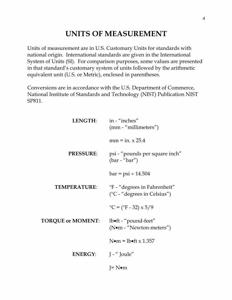
UNITS OF MEASUREMENT Units of measurement are in U.S. Customary Units for standards with national origin. International standards are given in the International System of Units (SI). For comparison purposes, some values are presented in that standard’s customary system of units followed by the arithmetic equivalent unit (U.S. or Metric), enclosed in parentheses. Conversions are in accordance with the U.S. Department of Commerce, National Institute of Standards and Technology (NIST) Publication NIST SP811.
LENGTH: in - “inches” (mm - “millimeters”)
mm = in. x 25.4
PRESSURE: psi - “pounds per square inch”
(bar - “bar”)
bar = psi ÷ 14.504
TEMPERATURE: °F - “degrees in Fahrenheit” (°C - “degrees in Celsius”)
°C = (°F - 32) x 5/9
TORQUE or MOMENT: lb•ft - “pound-feet”
(N•m - “Newton-meters”)
N•m = lb•ft x 1.357
ENERGY: J - “ Joule” J= N•m

5
BACKGROUND Work on this project represents the continuation of years of research and other activities undertaken to support the technical requirements specified in present MSHA regulations for explosion-proof enclosures. PAST RESEARCH About 30 years ago, the Pennsylvania State University (PSU), Department of Mineral Engineering, was given a research grant1 to study explosion-proof enclosure design characteristics. Later, the Southwest Research Institute (SwRI) was awarded two research contracts2, 3 concerning explosion-proof enclosure requirements cited in MSHA regulations. One of the contracts was to determine the effective degree of safety afforded for explosion-proof enclosures built according to MSHA requirements, and the other contract was awarded to develop guidelines for mining equipment manufacturers to follow in designing explosion-proof enclosures to meet MSHA specifications. In more recent times, the MSHA, Approval and Certification Center (A&CC), conducted a conceptual review of both foreign4 and domestic5 standards pertaining to the design and testing of explosion-proof equipment. The results of all this work served as a precursor to this investigative effort. PSU The Pennsylvania State University study involved a literature search to find test or relevant theoretical data to substantiate the design specifications contained in MSHA regulations for explosion-proof enclosures. Another important aspect of this research was to analyze the international “state-of-the-art” hazard reduction methods and techniques used for housing electric apparatus on equipment in mining applications. This information was expected to aid MSHA in developing performance requirements, in lieu of explicit design specifications, for explosion-proof enclosures on permissible electric equipment used in U.S. mines. The final report from this work concluded1, p42-43 that some of MSHA’s design criterion for explosion-proof enclosures could be substantiated.
6
Surface temperature requirements of 150 °C were considered adequate and the required minimum internal design pressure of 150 pounds per square inch gauge (psig) affords some margin of safety, about 1.5 times more than that theoretically necessary for containing a methane-in-air explosion. However, in terms of safety, gap dimensions were judged to be about ten (10) times smaller than those necessary to successfully contain an internal explosion of a flammable concentration of methane within an enclosure. The study also concluded that MSHA’s design specifications for mechanical strength and explosion transmission could be replaced with suitable performance specifications (i.e., explosion testing to obtain a “reference pressure” and hydrostatic pressure testing at some suitable factor of safety -- 150 psig minimum). Furthermore, it noted that it would be feasible to eliminate hydrostatic pressure testing, if engineering computations show the enclosure capable of withstanding an internal pressure calculated using larger factors of safety than that afforded by existing MSHA regulations. Under these scenarios, the report also suggested that present flange and joint criteria should be retained, unless further research in this area proves otherwise. The PSU literature review indicated that the international community believed the “state-of-the-art” for explosion protecting mine electrical equipment was represented in publications by the International Electrotechnical Commission (IEC). The report suggested that MSHA testing of foreign made enclosures could be eliminated if the IEC recommendations on equipment certified by national and international testing authorities were accepted by MSHA. However, the report also concluded that this action could cause problems, as MSHA would need to eliminate mechanical design specifications, and the flange and gap requirements would need to be revised. It further stated1, p44... “Considering MESA’s [MSHA’s] current field inspection procedures (mainly the use of a gap gauge), the total adoption of the IEC recommendations would more than likely require a different inspection procedure. In other words, more variables than the maximum permissible gap enter into the safety picture. These new procedures might make such a change unwise. However, by changing the mechanical strength requirements, the schedule would be more in alignment and performance tests would result.”
7
SwRI The work done by PSU offered some insight on the theoretical design aspects for MSHA requirements concerning explosion-proof enclosures. SwRI was awarded two research contracts to further develop this work. In particular, the Agency was interested in determining the degree of safety provided for explosion-proof enclosures that are constructed according to the minimum design specifications contained in MSHA regulations. This information was considered paramount in establishing a baseline reference to develop more performance oriented requirements without compromising the existing factors of safety. The margins of safety for four commercially available “MSHA-Certified” explosion-proof enclosures were evaluated by a combination of analysis and testing. A finite-element computer program, ANSYS®, was chosen as the primary analytical tool. ANSYS®, produced by ANSYS, Inc., is a finite element simulation tool that incorporates "multiphysics" to simulate real world conditions. This allows users to analyze parts for behavior under multiple physical forces simultaneously. Both ANSYS® and closed-form solutions were used to calculate the maximum strains and stresses in the enclosures. These analyses included elastic and plastic material behavior, weld joint strength, bolt deformations, and both static and dynamic internal pressure loads. Corresponding strains and displacements were measured during hydrostatic testing for comparison with analytical predictions. Safety factors for the four enclosures were based on both analysis and experimental results. Wide variations in the overall strength between each enclosure were found. The safety factors ranged from 0.73 for a large steel fabricated enclosure having an aluminum cover to 4.83 for a small cylindrical cast steel enclosure and cover. The design criterion of a maximum 0.040-inch per linear foot permanent deformation after static loading to 150 psig, used to compute the factors of safety, was found to be a more severe design constraint for enclosures than internal explosions of methane and air. Thus, it was possible to have an enclosure with a 150 psi design safety factor less than one, as judged by the deformation criteria, and still perform satisfactorily in the explosion tests required by MSHA. None of the enclosures ruptured at an internal pressure of 150 psig. Weld
8
joints in a 926 cubic inch enclosure, however, partially failed at pressures as low as 60 psig and permanent deformations of 0.31-inch per linear foot were produced in the enclosure at 150 psig. Guidelines for manufacturers to follow in designing explosion-proof enclosures that meet MSHA requirements were prepared by SwRI as an outgrowth of the contract awarded to study safety factors. The guide concentrated on design features which affect enclosure strength, ruggedness, endurance, and flamepaths. Internal static and explosion pressures, external impact and thermal heating loads were also addressed, as well as, the proper selection of materials and welding procedures. The design guide was organized to address the various steps in the design process in the approximate order in which they were expected to be accomplished. PRESENT EFFORTS A review of the past research work on the characteristics of explosion-proof enclosures and the in-house review of pertinent standards provided an impetus for the A&CC to explore the feasibility of developing a modified approval approach in evaluating enclosures designed and constructed according to nationally and internationally recognized standards for explosion-proof equipment. On June 17, 2003, MSHA published (68 FR 36407) a final rule, 30 CFR Part 6 -- Testing and Evaluation by Independent Laboratories and Non-MSHA Product Safety Standards. The rule established alternate protocols for testing and evaluation of products that MSHA approves for use in areas of underground mines where permissible equipment is required. This final rule also permits manufacturers to request MSHA approval of their products based on non-MSHA product safety standards. Section 6.20(b) of this regulation stated that:
“MSHA will publish its intent to review any non-MSHA product safety standard for equivalency in the Federal Register for the purpose of soliciting public input.”
9
Section 6.20(c) further explained that:
“A listing of all equivalency determinations will be published in this part 6 and the applicable approval parts. The listing will state whether MSHA accepts the non-MSHA product safety standards in their original form, or whether MSHA will require modifications to demonstrate equivalency. If modifications are required, they will be provided in the listing. MSHA will notify the public of each equivalency determination and will publish a summary of the basis for its determination.”
On December 1, 2003, MSHA published (68 FR 67216) its intention to perform an equivalency review of the International Electrotechnical Commission's (IEC) Standards for Electrical Apparatus for Explosive Gas Atmospheres, Part 0, General Requirements (IEC 60079- 0); Part 1, Flameproof Enclosures “d” (IEC 60079-1); and Part 11, Intrinsic Safety (IEC 60079-11). The IEC is a worldwide organization for standardization comprising all national electro-technical committees. These standards are subparts of the IEC standards for hazardous location equipment. Work on this project was initiated to perform the equivalency determination between MSHA regulations and the IEC standards for explosion-proof (flameproof) enclosures. INTRODUCTION There are many methods that may be employed to mitigate the explosion potential from operating electric equipment in hazardous locations. Such techniques, some of which are recognized in both the U.S. and in foreign countries, include the use of explosion-proof (flameproof) enclosures, as well as other mitigation methods such as: pressurization; encapsulation (potting); hermetic sealing; oil immersion; powder filling; increased safety; intrinsic safety; etc. The most common and easily recognizable protection method for housing electrical apparatus in hazardous mining locations is equipment designed to be explosion-proof.
10
Explosion-proof (flameproof) enclosures for use in mining applications must be both rugged in construction and able to contain an internal explosion without allowing hot gases, sparks, or flashes to escape and potentially ignite a flammable mixture surrounding the enclosure. This must be accomplished without excessive distortion to the enclosure in areas that affect explosion-proof integrity. Also, the maximum temperature of the external surfaces of the enclosures, under normal operation, must not ignite a surrounding flammable atmosphere or layered combustible materials. In U.S. mining applications, explosion-proof enclosures may not discharge visible flames from the enclosure when explosion tested. The same general definition applies to explosion-proof (flameproof) equipment used in other U.S. industries and in foreign countries, except the discharge of visible flame criteria is omitted. OVERVIEW To assist the reader in fully appreciating the concept and reasoning behind the information presented in this report, a review of some basic concepts related to explosion-proof protection methodology is presented. Explosion-proof methods are utilized to minimize the potential for the loss of life and property due to explosions and fires in U.S. mines. Explosion-proof enclosures are found on all electric- and diesel-powered mining machines located in the gassy areas of underground coal and metal and nonmetal mines in the United States. These enclosures are not necessarily gas tight, and an ignitable gas mixture may be created within a properly designed, constructed, and maintained explosion-proof enclosure in a mine environment where high concentrations of methane may be present. Methane may enter the enclosure from diffusion through openings, even though they are very small. Also, methane may enter the enclosure through a process known as “breathing.” Breathing results from the expansion of the atmosphere within the enclosure, caused by heat generated from normal operation of the enclosed electric equipment, and contraction of the atmosphere as the air cools. Methane may also enter the enclosure when covers are removed for inspection and repair.

11
Explosion-proof enclosures have been researched since approximately 1906. Even so, some researchers7, p139 believe that there is little understood about the mechanism by which they are effective. In preparation for the analysis considered necessary to complete this project, several publications and research reports have been reviewed to gain a basic understanding of the fundamental principals related to explosion-proof enclosure design and expected performance characteristics. Two documents were found to be extremely valuable in researching material for this project. One is a publication by Morley6, based on work done for the U.S. Bureau of Mines, and the other is a book by Magison7, which is based on work done by the Instrument Society of America Recommended Practice Committee SP12. Other reference documents include a book written by Schram8 on behalf of the National Fire Protection Association (NFPA) and a Canadian Standards Association (CSA) publication by Bossert9. Except for Morley’s publication, the main interest served by most of the other documents reviewed was for industries other than mining. Additional background information pertaining to MSHA regulations was sought through reviewing research reports and other archived documents pertaining to historical changes that have been made to the regulations for explosion-proof enclosures. It was found that, through the years, MSHA requirements concerning permissible electric equipment and explosion-proof components have changed at least seven times. SCOPE OF WORK The scope of work for this project was limited to the design, construction, and test requirements associated with explosion-proof (flameproof) enclosures. Enclosures that are typically used on electric-powered mining equipment in the U.S. are modeled throughout the report to provide a uniform basis for comparison. This report is structured into several parts. An “Abstract,” “Definitions,” “Units of Measurement,” “Background,” and “Introduction” are provided to brief the reader on the purpose and intended significance of the work.

12
The “Discussion” portion of this report is further separated into several subsections, containing technical information associated with each specific feature considered important for the comparison. A summary is also provided an effort to present a qualitative and, to the extent practicable, a quantitative comparison of the technical requirements. Finally, the report ends with a “Conclusions and Recommendations” section concerning the type and nature of the “modifications” that must be made for explosion-proof enclosures, designed and tested according to IEC standards, to be considered as providing “at least the same degree of protection” as those enclosures designed and constructed according to MSHA regulations. A “Reference” section is provided to list the source for annotated material throughout the text of the report. An “Appendix” section is also included at the end of the report which provides a listing of the selected sections of the MSHA10, 11 regulations and selected clauses of the IEC12, 13 standards that were considered for review and comparison. A table titled “Summary of Requirements -- MSHA Regulations and IEC Standards for Selected Features of Explosion-proof (flameproof) Electrical Enclosures” is also included in the appendix section of the report. This table is intended to provide the reader with an overview of the similarities and differences between selected technical requirements of MSHA regulations and the IEC standards. DISCUSSION The following material is provided in order to convey information concerning a number of features considered common to the design, construction, testing and evaluation all explosion-proof enclosures. Design and evaluation features such as mechanical strength, flamepaths, lead entrances, explosion tests (including pressure tests), product conformity, and new technology are discussed and summarized for both of the standards and regulations reviewed. Other features such as insulating materials, electrical clearances, voltage limitations, and grounding methods were not addressed, since their adequacy is not considered part of the enclosure certification activities performed by MSHA.
13
MECHANICAL STRENGTH An ideal explosion-proof enclosure would not have any openings except for the cable entry. After the equipment is built, the cover could be welded to effectively seal the unit. Electric equipment has a need for regular maintenance and repair, so some form of removable cover is required to gain access to the electrical components and circuits inside of the enclosure. Typical covers are cylindrical and threaded in place, or are square or rectangular in shape and bolted in place with a number of fasteners. For a cylindrical cover, the threaded joint must be wide enough to provide sufficient flamepath length and the entire cover strong enough to prevent distortion in the flamepath area due to explosion pressure. Several other factors must be considered for bolted covers.
• The thickness of the flange and the spacing of the bolts must not allow undue distortion of the flange joint between the bolts during an explosion.
• A bolted cover must be strong enough (by thickness, shape, or
ribbing) to prevent undue distortion which might enlarge a flamepath gap during an explosion.
• The bolts or other fastenings must have adequate strength and be of
sufficient number to prevent stretching or rupture during an explosion.
According to prudent engineering practice, a safety factor is often applied to the mechanical strength requirement to address a number of variables, such as, variations in material strength and material thickness during the manufacturing process and deterioration due to corrosion. A safety factor also reflects the basic function of an enclosure, which is to protect the life and safety of miners by containing any internal explosion within the confines of the enclosure. These design safety factors generally vary between the standards. Some standards set minimum constructional requirements for explosion-proof enclosures while others are more performance oriented.

14
Some standards include provisions for the use of surface preparations to minimize the effects of corrosion on flamepath surfaces. Minimum wall thickness specifications are often cited in standards to provide a degree of protection against the creation of high external surface temperatures as a result of arcing faults within the enclosure. Such arcing faults could cause burn-through of the enclosure wall affecting the integrity of the enclosure. MSHA MSHA’s design and construction requirements for explosion-proof enclosures are grouped according to three enclosure volume categories: less than 45 cubic inches (737 cubic centimeters); between 45 cubic inches and 124 cubic inches (2032 cubic centimeters); and, greater that 124 cubic inches. These requirements are considered as the minimum design and construction criteria for explosion-proof enclosures. They result from years of observation and experience in evaluating explosion-proof enclosures built specifically for use on electrical mining equipment used in hazardous areas of underground mines. Explosion-proof enclosures are required to be designed to withstand a minimum internal pressure of 150 psig (10.34 bar). Castings must be free from blowholes and welded joints forming enclosure walls must be made in accordance with the American Welding Society Standards. In general, the regulation implies that the enclosure is to be of metal (i.e., steel, aluminum, brass) construction. External rotating parts must not be constructed of aluminum alloys containing more than 0.6% magnesium. Other materials may be used to form parts of an enclosure, when MSHA determines that alternate materials provide the same degree of protection. Glass and polycarbonate window and lens materials have been evaluated and may be used on explosion-proof enclosures with certain restrictions. Other non-metallic materials may be evaluated on a case-by-case basis under the new technology provisions in existing regulations. For an enclosure having a free internal volume greater than 124 cubic inches, MSHA requirements specify that the nominal minimum dimensions for walls to be at least 1/4-inch (6.35 mm) thick, with 1/2-inch (12.7 mm) thick flanges and covers. Enclosure fasteners such as machine bolts, cap screws, or studs must be at least 3/8-inch (9.525 mm) in diameter

15
with a minimum thread engagement into the flange equal to or greater than the diameter of the fastener. All fasteners used to secure parts of explosion-proof enclosures must have provisions to prevent loosening, such as lockwashers or equivalent. Fasteners must be provided at all corners and be spaced (between bolt centers) no greater than six (6) inches (152.4 mm) apart. Steel dowel pins may be used in the place of some of the fasteners as long as the spacing between centers of the fasteners, on either side of the pin, does not exceed five (5) inches (127 mm). The adequacy of the spacing for fasteners is judged on the basis of the size and configuration of the enclosure, strength of materials, and explosion test results. Static pressure tests may, at MSHA’s discretion, be required if it is determined that the design does not permit complete visual inspection or when the joints forming the enclosure are welded on one side only. IEC The IEC standards related to the mechanical strength of an enclosure are performance oriented. There is no minimum thickness or strength specifications specifically cited in the standards for enclosure walls, flanges, or covers. Enclosure strength, including bolt size and spacing, is evaluated on the basis of an enclosure’s ability to withstand the effects from explosion and overpressure testing. Testing results are acceptable if the enclosure does not suffer any structural damage or permanent deformation that may affect its flameproof (explosion-proof) properties. Some enclosures or features of enclosures are also subjected to impact tests. Impact tests are required for: light metal and cast metal enclosures; enclosures constructed in whole or in part with non-metallic materials; guards; protective covers; cable entries; and, for light-transmitting parts. Impact tests are not required for fabricated (welded) metal enclosures, unless the walls are less than 3 mm (0.118-inch) thick or they are assembled with light metals. In such cases, the parts are tested with impact energies ranging from 7 to 20 Joules using a 1 kg (2.2 pound) test mass with a 25 mm (0.984-inch) diameter hardened steel hemispherically shaped head. The IEC has provisions for evaluating non-metallic enclosures and non-metallic parts of enclosures and for evaluating enclosures constructed with light metals. Enclosures constructed, either in whole or in part, with non-

16
metallic materials are subjected to “type” tests to address issues related to the physical properties of non-metallic materials versus metallic materials. Type testing addresses performance related concerns pertaining to the material’s thermal endurance to heat or cold, resistance to light, resistance to chemical agents, and surface resistance with respect to the accumulation of static charges. These tests are performed in a specific order, using six samples of the product, and conclude with the required impact, explosion, and pressure tests. Enclosures constructed with light metals are limited, by mass, to no more than 15% in total aluminum, magnesium, and titanium and to no more than 6% of magnesium and titanium combined. Threaded holes for fasteners which secure covers intended to be opened in service for adjustment, inspection, and operational reasons may only be tapped into non-metallic materials and light metals when the thread form is compatible with the material used for the enclosure. Light metal or non-metallic fasteners may be used for enclosures constructed with light metals, if the fastener material is compatible with that of the enclosure. Holes for threaded fasteners in mining enclosures must be threaded for a distance that will allow for a thread engagement at least equal in length to the major diameter of the fastener and allow for 1 thread of free space to prevent bottoming. Where necessary, a means must be provided to prevent fasteners from being loosened by vibration. Although not specifically stated in the standard, lockwashers or similar devices may be employed to fulfill this purpose. The IEC further recommends that the heads of fasteners which may be susceptible to mechanical damage should be protected by shrouds or counter-bored holes. Certain parts of enclosures, necessary to maintain explosion-proof integrity or used to prevent access to energized circuits, are required to be secured in a manner so that they may only be released or removed with the aid of a tool. The structural integrity of enclosures built according to IEC standards is verified through both prototype and routine pressure testing. During prototype testing, the enclosure must be capable of withstanding pressures 1.5 times the maximum explosion (reference) pressure measured for that enclosure, 3.5 bar (50.76 psig) minimum. Once an enclosure is qualified by the testing authority, the manufacturer is obligated to conduct routine pressure tests at 1.5 times (3.5 bar minimum) the maximum explosion
17
pressure measured for that enclosure during prototype testing. Routine tests are not required for enclosures with volumes less than 10 cubic centimeters (0.61 cubic inches) or for other enclosures, except those with welded construction, if the prototype static pressure tests were made at 4 times the maximum explosion pressure measured for that enclosure during prototype testing. Enclosures with welded construction are always subject to routine testing. SUMMARY From the foregoing discussion, MSHA has very explicit design and construction specifications for explosion-proof enclosures. The IEC standards rely on performance tests to verify structural design integrity and offer little in the way of constructional specifications. From their inception, MSHA’s requirements have presented a “cook book” approach for manufacturers to follow in designing explosion-proof enclosures. Enclosures constructed using the minimum specifications cited in the regulations usually produce an enclosure capable of containing methane-in-air ignitions, without any permanent deformations affecting explosion-proof integrity or rupture of any parts forming the enclosure. Research2, p202-203 conducted during the early to mid 1980's suggests that the minimum design specifications for enclosures having large volumes in excess of 124 cubic inches may not be capable of meeting the 150 pounds per square inch (gauge) design requirement without any permanent distortion, unless additional precautions are taken to reinforce or otherwise strengthen the enclosure with thicker walls, covers, flanges, larger size bolts, etc. None of the enclosures evaluated as part of this research effort exhibited catastrophic material failure with an internal pressure of 150 psig applied, and all of the enclosures had successfully passed MSHA’s explosion tests. Because of this research and the fact that explosion-proof enclosures were becoming larger and larger in size, MSHA refined its position concerning the allowance for permanent deformations that may be sustained during hydrostatic pressure testing of enclosures at the 150 psig rating. Manufacturers must include provisions in their static pressure testing protocols that do not permit permanent distortions that would exceed

18
0.040-inch per linear foot (3.333 mm per linear meter) or any distortion or damage that may affect the explosion-proof integrity of the enclosure. However, MSHA only requires such testing under special conditions of the enclosure’s design or use, and does not require prototype or routine static pressure testing to ensure that all enclosures meet the 150 psig design specification. The IEC standards have provisions to verify structural integrity with prototype and routine pressure testing of the enclosure. The goal for all explosion-proof enclosure standards is to produce enclosures that are strong enough to contain explosion pressures, with some additional factor of safety. MSHA’s safety factor is based on a value of about 1.5 times the maximum pressure9, p7 (104 psig, 7.17 bar) that can be realized from a methane-in-air ignition in a closed vessel, without the effects of pressure piling. The use of a safety factor value based on a pressure above the maximum closed vessel pressure allows for minor changes in enclosure design and modifications in the placement of internal components, without the need for conducting additional explosion tests. The IEC standards rely on the maximum recorded explosion pressure (reference pressure) for a specific enclosure to serve as the basis for defining the minimum pressure that the enclosure must be capable of sustaining and, therefore, the IEC standards may not be as flexible as MSHA in allowing for enclosure modifications. This approach causes some difficulty in reconciling the differences in the IEC standards with MSHA’s explosion-proof enclosure design requirements. Enclosures evaluated according to the IEC standards may not always be tested to ensure that they are capable of withstanding internal pressures of 150 psig, or more. For example, typical3, p24 peak explosion pressures recorded by MSHA during explosion testing generally range from a low of about 60 psig (4.14 bar) to a high of around 80 psig (5.52 bar), depending on the enclosure’s size, configuration, type of flamepaths and number of openings. Enclosures that develop 60 psig to 80 psig as a reference pressure test according to the IEC standard would only require overpressure testing with test values ranging from 90 psig (6.205 bar) to 120 psig (8.27 bar). This is less than the 150 psig minimum construction requirement of MSHA. A second concern is that the IEC standards allow for permanent distortion of the enclosure during pressure

19
testing and explosion testing, as long as it does not affect the explosion-proof characteristics. MSHA requirements restrict the amount of permanent distortion that may be sustained by any external surface of an enclosure during testing to no more that 0.040-inch per linear foot. In most cases, MSHA’s test protocol promotes a higher degree of perceived safety than that afforded by the IEC standards. Most explosion-proof enclosures used in U.S. mining operations are fabricated or cast from iron, steel, aluminum, or brass. MSHA and the U.S. mining industry have little experience with explosion-proof enclosures constructed with non-metallic materials. In such cases, non-metallic parts have been limited to glass or polycarbonate materials used for light transmitting view ports or in the construction of luminaires. MSHA has established criteria for evaluating the specific materials used in these limited applications. The IEC standards have special provisions and tests to evaluate many types of non-metallic materials for constructional uses. Such evaluation and testing exceeds the currently required thermal shock, impact, surface temperature and explosion tests utilized in MSHA’s current evaluation of non-metallic materials. It is conceivable that a non-metallic enclosure could be fabricated to meet the requirements of the IEC standards that would not be able to be tested and evaluated by MSHA’s current procedures. For this reason, it may be prudent to avoid the introduction of these types of explosion-proof enclosures into the U.S. mining community until such time that MSHA has had more experience with non-metallic materials. MSHA would need to develop appropriate guidelines for addressing a number of issues concerning the evaluation, testing, care, maintenance and durability associated with operating this type of equipment in a U.S. mining environment. It is anticipated that such work will be undertaken under the new technology provisions in existing regulations. MSHA requirements for the size, number, and spacing for fasteners that secure parts of explosion-proof enclosures are well established and have been in place for over 30 years. In general, the IEC standards regarding the design and construction of enclosure fasteners would be acceptable to MSHA. The IEC standards do not specify a specific minimum size and type for fasteners; however, there are some requirements for threaded parts
20
to have a maximum number of threads per inch and minimum thread engagement which are considered compatible with MSHA specifications. Also, the IEC standards do not clearly define a maximum spacing distance between fasteners, nor the minimum number of required fasteners. The IEC standards do not preclude the use of lockwashers or other devices to secure fastenings on explosion-proof enclosure covers and related parts, therefore there would be no conflict with MSHA’s specific requirements for the use of lockwashers and other devices to secure integral parts of enclosures. In the interest of establishing equivalency between MSHA regulations and the IEC standards, the mechanical strength features of an enclosure could be evaluated through the use of engineering analysis and special performance testing. The results could then be compared to a comparable enclosure designed according to MSHA specifications. For example, MSHA could allow for larger distances between bolts without diminishing the safety factor provided by the regulation and the current restrictions regarding the minimum number of fasteners could be reconciled if an engineering analysis shows that the enclosure can sustain static pressures in excess of 150 psig. In such cases, the enclosure must demonstrate successful containment of internal ignitions without igniting the surrounding flammable atmosphere, when explosion tested with more sensitive test gases at an internal pressure of 150 psig or more. Similar concessions could be made for the minimum wall, cover, and flange thicknesses cited in existing MSHA regulations, except that the engineering analysis would need to address a comparison of the ruggedness features (i.e., impact strength, weld integrity, both elastic and plastic plate deflections, yield stress, etc.) of a comparable enclosure designed to MSHA requirements that is designed to withstand an internal pressure of 150 psig without excessive distortion. It would seem to be prudent, however, to maintain current stipulations for uniformity in fastener size and length (to the nearest metric equivalent) and for securing fasteners against loosening, in order to maintain conformity in the inspection and facilitate maintenance of enclosures in the field.
21
Experience with contemporary designs of large enclosures indicates that the minimum design specifications for enclosure walls, covers, etc. provided in MSHA regulations must be exceeded to accomplish an enclosure design that can withstand an internal pressure of 150 psig without significant permanent distortion. Therefore, the concessions noted above will not likely result in radically different enclosure designs with regard to mechanical strength between enclosures designed and tested according to either the IEC standards or MSHA regulations. FLAMEPATHS All explosion-proof enclosures have openings through which hot burning gases may escape following the ignition of an explosive gas within the enclosure. These openings are necessary for access covers, operating rods and spindles (shafts), and cable entries. Joints, mating surfaces formed at the interface of these parts to the enclosure, form flamepaths. There are two essential properties of a flameproof joint:
• The maximum clearance between mating surfaces of a joint is referred to as the maximum gap.
• The length of the path between mating surfaces from inside the
enclosure to the outside is referred to as the width of the joint or flamepath.
Both MSHA and the IEC specify maximum gaps and set minimum flamepath lengths for different designs of flamepath joints in accordance with the internal volume of the enclosure. Both standards also set the minimum distance from the inside of an enclosure to any holes located in enclosure surfaces or covers and detail requirements for the use gaskets (o-rings) used to minimize the ingress of moisture and foreign matter. MSHA MSHA’s flange and joint requirements for explosion-proof enclosures are grouped according to three enclosure volume categories: less than 45 cubic inches (737cubic centimeters); between 45 cubic inches and 124 cubic inches (2032 cubic centimeters); and, greater that 124 cubic inches. Typical mining
22
enclosures fall into the greater than 124 cubic inch category. These enclosures must have at least a 1-inch (25.4 mm) flamepath with no more than a 0.004-inch (0.1016 mm) gap for flat plane flanged joints. Compound (step) joints (joints in different planes) allow for 3/4-inch (19.05 mm) long flamepaths, with a 0.006-inch (0.1524 mm) gap for the plane portion and 0.008-inch (0.2032 mm) for the portion perpendicular to the plane. If a combination plane/cylindrical joint is employed, the allowable diametrical clearance is 0.008-inch when the portion perpendicular to the plane portion is 1/4-inch (6.35 mm) or greater. If the perpendicular portion is more than 1/8-inch (3.175 mm) but less than 1/4-inch, the diametrical clearance may not exceed 0.006 inches. If a cylindrical joint is employed, it may have a maximum diametrical clearance of 0.010-inch (0.254 mm) with a minimum flamepath length of 1-inch. Shafts or operating rods through journal bearings may not be less than 1/4-inch in diameter. Also, shafts centered by ball or roller bearings must have a minimum flamepath length of 1-inch with a diametrical clearance not exceeding 0.030-inch (0.762 mm). The minimum distance from the inside of the enclosure to the edge of a bolt hole or a hole for a steel dowel pin is specified as 7/16-inch (11.11 mm). A minimum dimension of 1/4-inch is acceptable provided the clearance around the bolt (dowel pin) does not exceed 1/32-inch (0.79 mm). Otherwise, the maximum diametrical clearance between the bolt body (dowel pin) and the unthreaded hole(s) through which it passes may not exceed 1/16-inch (1.58 mm) for a distance equal to the minimum thickness of the cover. This maximum clearance only applies when the bolt is located within the flamepath. Bolt holes in flanges may not penetrate into the enclosure and 1/8-inch of stock must be left in the bottom of all blind holes. Flat surfaces between bolt holes that form any part of a flame-arresting path must be plane to within a maximum deviation of one-half the maximum allowable clearance specified for that type of joint and enclosure volume. Threaded covers and mating parts must be designed with Class 1A and 1B (coarse, loose-fitting) threads. The flame-arresting path of threaded joints must also conform to the same requirements for explosion-proof enclosures. All metal surfaces forming a flame-arresting path must be finished during the manufacturing process to not more than 250 microinches (6.35 micrometers). A thin film of nonhardening preparation to inhibit rusting may be applied to finished

23
metal surfaces as long as the final surface can be readily wiped free from any foreign materials. A gasket may not be used between any two surfaces forming a flame-arresting path, except as follows: (1) A gasket of lead, elastomer, or equivalent will be acceptable provided the gasket does not interfere with an acceptable metal-to-metal joint; and, (2) A lead gasket(s) or equivalent will be acceptable between glass and a hard metal to form all or a part of a flame-arresting path. Also, o-rings, if used in a flame-arresting path, must meet the following: (1) When the flame-arresting path is in one plane, the o-ring must be located at least one-half the acceptable flame-arresting path length within the outside edge of the path; (2) When the flame-arresting path is one of the plane-cylindrical type (step joint), the o-ring must be located at least 1/2-inch (12.7 mm) within the outer edge of the plane portion, or at the junction of the plane and cylindrical portion of the joint, or in the cylindrical portion. The widths of any grooves for o-rings will be deducted in measuring the widths of flame-arresting paths. IEC The IEC lists flamepath gaps for enclosures covering a range in volume from less than 100 cubic centimeters (6.1 cubic inches) to over 2000 cubic centimeters (122 cubic inches), in 4 volume categories. Flamepath gaps are given based on flamepath length and are categorized according to type of joint (i.e., flanged, cylindrical, or spigot joints; shafts with sleeve bearings and rotating shafts centered by roller bearings). Maximum clearances (gaps) between flanges or gaps between cylindrical surfaces are further defined for specific flamepath lengths (joint widths). Flamepath lengths vary from a minimum of 6 mm (0.236 in) to those greater than 25 mm (0.984 in), with maximum clearances increasing as the length increases. No intentional gaps are permitted except when necessary for quick acting doors and covers, in which case, the maximum gap may not exceed those specified in the standards. For a nominal 25 mm flamepath length, the IEC would permit a gap or clearance as large as 0.50 mm (0.0197 in) for plane flanged and spigot joints and for operating rods and spindles. Shafts with sleeve bearings may have a diametrical clearance of up to 0.60 mm (0.0236 in) for flamepath lengths greater than 40 mm (1.575 in). Shafts with rolling

24
element bearings may have a diametrical clearance up to 0.80 mm (0.0315 in) for flamepath lengths equal to or greater than 40 mm, as long as the maximum radial clearance does not exceed two-thirds of the maximum gap permitted, depending on the specified flamepath length. The minimum radial clearance for shafts with sleeve bearings and for shafts centered by ball or roller bearings may not be less than 0.05 mm (0.00197 in). Labyrinth or serrated (threaded) joints that do not conform to the IEC flange and joint design parameters are permitted. However, the construction and test requirements for such joints are not specifically described in the standard. Testing of such joints may require a greater number of explosion tests and the introduction of additional safety factors, as may be determined by the testing laboratory. Bolt holes may not penetrate into an enclosure, and the minimum distance from the inside of the enclosure to the edge of a bolt hole is specified as 9 mm (0.354 in) for joints with widths greater than or equal to 25 mm. Threaded joints must have a pitch from 0.7 mm (0.0276 in), medium or fine tolerance according to ISO 965-1 and ISO 965-3, with a minimum of 5 threads engaged and a length of engagement equal to or greater than 5 mm (0.197 in) for enclosures less than 100 cubic centimeters in volume. A thread engagement greater than or equal to 8 mm (0.316 in) is required for enclosures having a volume greater than 100 cubic centimeters. Where the pitch exceeds 2 mm (0.079 mm), special precautions may be necessary to ensure that the enclosure passes the test for non-transmission of an internal ignition. Cylindrical threaded joints which do not conform to ISO 965-3 may be permitted if the test for non-transmission of an internal ignition is passed. The surface finish of the joints must be machined to an average roughness (ISO 468) which does not exceed 6.3 micrometers (248 microinches). The surfaces of joints may be protected against corrosion, but coating with paint or similar material is not normally permitted, unless the material and the application procedure have been shown not to adversely affect the flameproof (explosion-proof) properties of the enclosure. Joint surfaces may be electroplated up to a thickness of 0.008 mm (0.0003 in). If gaskets (including o-rings) of compressible material are used for protection against moisture or dust, they must be applied as a supplement

25
to and not included in the flamepath length. This requirement does not apply to the entry of conductors and cables or to transparent elements of luminaires. Also, a gasket may not prevent the proper closure of the flameproof joint to meet the specified flange and joint requirements of the standard. If a gasket is provided in the plane part of a combination plane-cylindrical joint (spigot joint), the gap of the plane part is to be measured after compression of the gasket. The minimum width of the cylindrical part must be maintained before and after compression of the gasket. SUMMARY A review of the flange and joint dimensions between MSHA regulations and the IEC standards shows a wide diversity in the maximum allowable gap and minimum width of flamepath allowed by each standard for a given enclosure volume. For example, the IEC plane flange gaps are nearly 5 times larger than the same joint design allowed by MSHA. This disparity is due to the difference in philosophy that forms the basis for the two standards. The IEC standards for mining enclosures are based on the Maximum Experimental Safe Gap (MESG) for methane. The standards call for at least a 2 times safety factor9, p26 on the explosion-proof (flameproof) joints. Methane is regarded9, p7 as having an MESG of 1.14 mm (0.0449-inch). Dividing this figure by 2, results in 0.57 mm (0.0224-inch). Rounding this off, the IEC came up with a figure of 0.50 mm (0.0197-inch) for a 25 mm (0.984-inch) or larger width of joint. For IEC Group IIA enclosure classifications (non-mining), which includes methane, this gap is reduced to 0.40 mm (0.0158-inch). This is because propane is used as the test gas for IEC Group IIA applications and is regarded9, p7 as having an MESG of 0.96 mm (0.0378-inch). Dividing this figure by two yields 0.48 mm (0.0189-inch) result. Rounding this off, the IEC came up with a 0.40 mm gap requirement for a 25 mm or larger plane flange joint. MSHA’s maximum allowable gaps for plane flange joints are based on the requirement for the non-transmission of visible flames from the enclosure. To accomplish this, the gaps must be less than the minimum gap that allows visible flames to escape and be observed. Research6, p386 suggests that a gap that prevents ignition (MESG) is 7 to 12 times larger than a gap

26
that quenches a visible flame (0.006-inch1, p28 for methane). Both the IEC standard and the MSHA regulation acknowledge that greater clearances are necessary for proper operation of rods and shafts. This is to minimize the potential for frictional heating due to rubbing of the contact surfaces, if the clearances are too tight, and to allow for normal wear of the joint surfaces. Without other information, the order of magnitude of differences for the gaps cited in the IEC standards compared to the gaps allowed by MSHA regulations may be considered significant in attempting to determine equivalency. However, the IEC standard clearly states that no intentional gaps may be permitted, except those necessary for proper operation of quick acting doors and covers. Therefore, the IEC would not allow such large gaps on prototypes with flat flanges and covers. The IEC standards are considered9, p27 as guidelines for the maximum gaps permitted on enclosures before they must be repaired or scrapped. MSHA has taken a different approach in that the regulations specify the maximum gaps that may be present on equipment when it leaves the factory, as well as in service. The clearances allowed and necessary for quick acting doors and covers by the IEC are much greater than those permitted by MSHA, therefore they would not be acceptable for explosion-proof enclosures used in U.S. mines, if the design is to be considered to provide at least the same degree of protection as that prescribed by MSHA regulations. Another area of special interest concerns the flamepath lengths (width) of the flameproof joints. The IEC standards provide for larger flamepath clearances (wider gaps) for flamepath lengths greater than 25 mm (0.984-inch). They also permit reduced flamepath lengths with a corresponding reduction in joint clearance for a specific enclosure size (volume) and joint design. MSHA regulations are somewhat inflexible in this area. MSHA sets forth only one set of flange and joint dimensions for each of the three enclosure volume categories listed in the regulations. In general, as the enclosure volume decreases, the MSHA allowed maximum gaps and minimum flamepath lengths also decrease proportionally. For example, a typical mining enclosure usually has an internal free volume in excess of 124 cubic inches. MSHA requires a minimum flamepath length of 1-inch for both plane and cylindrical type joints. The IEC standards allow these
27
joints to be as small as 12.5 mm (0.4921-inch) in length as long as the enclosure passes the prescribed performance tests. Analysis of flamepath lengths less than about 1-inch indicates a reduction in perceived safety factor developed by MSHA standards. Some researchers6, p387 have projected that each doubling of the width of a joint, up to an inch, tends to increase the MESG by a factor of about 30%. However, increasing the length beyond one inch has less impact on the MESG. Therefore, flamepath lengths smaller than one inch provide a lesser safety factor than those which are derived from MSHA requirements. Longer flamepaths, although permitted by MSHA regulations and other standards, have less dramatic effect on the MESG and the resultant relative safety factor computed for comparison purposes. Combination joints (stepped or spigot joints) and holes for fasteners within a flamepath are difficult to compare. Both MSHA regulations and IEC standards have provisions for accommodating the use of joints with radical (approximately 90 degrees) changes in flamepath direction. MSHA requirements specify design and dimensional constraints, while the IEC standards cite different constraints or performance criteria that are less explicit to provide for design flexibility. Both standards concede that final acceptance of labyrinth or serrated (threaded) joints require successful flame propagation testing with a suitable safety factor. This technique is consistent with the current methodology employed by MSHA in the evaluation of complicated or complex joints. The lack of quantitative comparison data is not considered as a significant concern in this equivalency determination. Evaluation of these complex joints would require complex analysis and may require specialized testing before acceptance by according to either standard. Both MSHA regulations and the IEC standards specify that the maximum finish of joint surfaces may not exceed a value of about 250 microinches (6.35 micrometers). The metal surfaces of joints often need protection against corrosion and the ingress of moisture and other foreign matter. Both of the standards provide for the use of seals (gaskets or o-rings) and the use of corrosion inhibitors on the surface of joints. Neither of the standards allow for the use of paint or other materials that may harden

28
over time, except the IEC has provisions for electroplating, as long as it can be shown that the electroplate material is compatible with the joint surfaces and that the plating will not peel or otherwise compromise the explosion-proof (flameproof) joint. O-rings (MSHA) or gaskets (IEC) may be utilized, with certain provisions:
• The gasket or o-ring area must be in addition to the required flamepath length.
• The gasket or o-ring may not reduce the effectiveness of the
flamepath when compressed (Exception – a gasket used as a cushion between a plane metal-to-glass flamepath joint.)
The IEC standards allow but do not require a gasket to be located outby the flamepath area. Since such a location could hinder inspection of the assembled in-service joint, MSHA regulations specify criteria for positioning of the o-ring when it is located within a flamepath joint. This criterion was developed specifically to allow field inspection and should not be compromised. From the foregoing discussion and limited MSHA experience with IEC designed and tested enclosures to date, an explosion-proof (flameproof) enclosure can be constructed with flamepaths that satisfy both MSHA regulations and IEC standards. There do not appear to be any design, construction or performance requirements that would create insurmountable technical conflicts with MSHA requirements. In order to be considered equivalent to MSHA regulations, some additional design considerations should be addressed. Slight differences in dimensional specifications created by Metric Unit (SI) to U.S. Customary Unit conversion should be considered equivalent from a technical basis. There is no practical or technical advantage in safety factor between a 1-inch long flange and a 25 mm long flange, or a 0.004-inch wide gap and a 0.1 mm wide gap. In addition, the standardized metric dimensions for bolt size and bolt hole clearances, material thicknesses, thread types and

29
gauges, must be acknowledged as MSHA equivalents in the interests of practicality. LEAD ENTRANCES Unless electric equipment is battery-powered, provisions must be made to connect to a supply of electric current. This may be accomplished with either a direct or indirect entry into the enclosure. For direct entry, cable entrance glands are often used for cables to enter explosion-proof (flameproof) enclosures. Glands are typically designed to use rope-like packing materials or sealing rings (grommets) to seal the openings for the cable through the enclosure walls to maintain the explosion-proof integrity of the enclosure. In some stationary applications involving conduit, the cable enters the enclosure through a specially designed conduit fitting which must be sealed with a setting compound to maintain the explosion-proof integrity of the enclosure. For indirect entry, electric power conductors first enter a connection box then enter an attached explosion-proof enclosure through a common opening in the connection box and the enclosure wall. The common opening must be closed with sealing compounds or with insulated bushings. The IEC standards do not require the connection box to be of explosion-proof construction. They allow for the use of an explosion-proof enclosure with an “increased safety” connection box. Increased safety is a method of explosion protection generally acceptable for electric apparatus that does not produce sparks or high temperatures in normal service. Increased safety requires additional measures be applied to provide security against the possibility of excessive temperatures and of the occurrence of arcs and sparks from component parts or from circuit failures. MSHA MSHA regulations acknowledge and cite requirements for only two types of direct cable entries into an explosion-proof enclosure. One has a stuffing box to accommodate rope-like packing material, and the other uses a similar arrangement designed for compressible elastomer materials such as grommets. Because MSHA does not consider flexible or rigid metal conduit appropriate for use on mobile mining equipment, MSHA
30
requirements prohibit the use of sealed metal conduit entries. Since MSHA regulations do not allow for nonexplosion-proof or increased safety connection boxes, indirect entry techniques addressed in the regulation are limited to the use of insulated bushings, openings closed with sealing compounds, or cables passing through large openings installed in the common walls between two explosion-proof enclosures. Explosion-proof plugs and mating receptacles (couplers) mounted to an enclosure wall are also used as a type of indirect entry. IEC IEC standards have provisions that include both direct and indirect types of entries for cables and conductors to enter a flameproof (explosion-proof) enclosure. Direct entry methods utilize packing glands or sealing materials which do not alter the flameproof properties of the enclosure. Such methods include special packing glands to accommodate sealing rings (grommets), as well as, special fittings which must be sealed with a setting compound. Flexible and rigid metal conduit and tubing are permitted under the IEC standards, even for mining applications. Indirect entry techniques addressed in the standard include the use of insulated bushings or wires or cables passing through openings sealed with setting compounds installed in the common walls between two enclosures. According to the IEC standards, a connection box is not required to be designed as explosion-proof. A terminal enclosure can be designed and constructed using other methods of protection, such as increased safety, that are recognized by the standards. Explosion-proof plugs and mating receptacles (couplers) mounted to an enclosure wall may also be employed. SUMMARY Because the IEC standards apply to multiple industries, it is not surprising to find metal conduit and setting compound entry designs specified as acceptable methods cited in the IEC standards for cable and conductor entries into explosion-proof (flameproof) enclosures. MSHA regulations, however, are devoted solely to mining applications. Through the years, MSHA determined that the use of flexible or rigid metal conduit is not considered appropriate for mobile mining equipment. This conclusion is based on the increased potential for pressure piling associated with the use of metal conduit, the associated problems with field replacement of sealing
31
(setting) compounds when cables are replaced on mobile electric equipment in mines, and the increased difficulty to repair and retrofit in-service mining machines. Although the IEC standards include mining applications, the differences in criteria peculiar to mining are not clearly delineated. The IEC, however, leaves final acceptance or rejection of an explosion-proof (flameproof) enclosure design up to the discretion of the approval authority or local jurisdiction. Acceptable direct and indirect cable entries as described in the IEC standards are considered to provide an equivalent factor of safety, as MSHA requirements. There are some differences in packing gland designs which may require some minor modifications to be consistent with MSHA. MSHA has specific design requirements for packing glands using rope-like packing materials and for gland arrangements using sealing rings (grommets) and the materials used in the packing glands. The IEC standards do not recognize the use of packing glands having rope-like packing materials and are generally more performance oriented than MSHA regulations. The most significant area of difference between MSHA regulations and the IEC standards pertains to the use of nonexplosion-proof terminal enclosures. The concept of increased safety, type “e” construction, was introduced9, p93 in Germany as an alternate to explosion-proof (flameproof) equipment. The IEC adopted a standard for increased protection in 1967. This could be somewhat problematic for MSHA acceptance of certain designs of equipment built according to foreign or domestic standards without some form of mitigation. The terminal compartments on these enclosures would need to be redesigned as explosion-proof in order to meet MSHA requirements. To summarize, cable and conductor entries for some explosion-proof enclosures designed to meet the requirements IEC standards may need modified to meet MSHA requirements. Such changes could range from simply replacing the packing material in glands with an “MSHA-Accepted” type to the re-machining or replacement of gland parts to meet MSHA’s design criteria. Some redesign would be necessary for those enclosures incorporating an “increased safety” nonexplosion-proof

32
connection box, in order to maintain the same degree of protection afforded by existing MSHA regulations. Nonexplosion-proof connection boxes have been prohibited on permissible electric equipment for the past 30 years. Prior to 1968, some nonexplosion-proof junction boxes, used to facilitate external connections that do not produce sparks or flashes as the result of normal operation, were permitted to be used on permissible electric equipment. Later, this regulation was changed to specifically require that these enclosures be explosion-proof, unless the circuits within are intrinsically safe. EXPLOSION TESTS To prevent the ignition of an external flammable atmosphere, an enclosure must be strong enough to withstand the internal explosion pressure and all openings must be tight enough to cool the hot gases so as not to cause an external ignition. Both Morley6 and Magison7 have written descriptions of the intricate mechanisms that influence flame propagation from within an enclosure to the surrounding atmosphere. Morley6, p384-385 seems to have summarized this phenomenon most succinctly:
“Since an internal explosion is a possible occurrence [in an explosion-proof enclosure], escaping gases generated in the explosion must not have sufficient energy to propagate the explosion to any hazardous atmosphere surrounding the enclosure. Conventionally, these hot gases are allowed to escape only through specially designed openings in the explosion-proof enclosure that provide long, narrow quenching distances. It is important that these gases be allowed to escape, otherwise internal pressures capable of rupturing the enclosure might develop.” Also, “...After an explosion is initiated inside the enclosure, a flame front propagates toward the chamber [enclosure] walls, burning the available combustible material. This raises the temperature and pressure inside the chamber [enclosure], and unburned gas, then heated burned gas, is forced through the flange gap. The jet of heated gas is cooled first by heat transfer within the flange gap. As it
33
exits from the enclosure, it may be further cooled by adiabatic expansion into the surrounding atmosphere; during this process, combustible gas from the outside methane-air mixture is also entrained in the jet. Although the additional gas provides fuel for combustion, it further cools the escaping gases. If the sum of this cooling does not lower the jet temperature below the gas ignition temperature, the explosion will propagate to the surrounding atmosphere. However, if the jet entrains an excessive amount of combustible gas in the last phase, the heat supplied by the jet will be less than the heat lost through cooling, and no ignition of the outside gas will occur. The action within the flange gap is believed to go beyond cooling. Combustion of a gas-air mixture does not proceed with a single chemical reaction but rather a chain of reactions. If the chain carriers or active molecules from a proceeding step are inhibited, for instance by contact with the flange wall, then combustion stops. This theory is also used to explain the protection properties of flame safety lamps.”
Certifying authorities verify the explosion characteristics of enclosures through performance testing. Explosion tests are important, in that they serve the basis for additional structural performance testing required by the standards and also provide some insight on the enclosure’s propensity to exhibit “pressure piling” conditions. This pressure increase is considered abnormal compared to pressure obtained in a constant volume combustion process with an internal gas pressure at or near normal atmospheric conditions at the time the gas is ignited within the enclosure. Although pressure piling has been observed in compartmented enclosures (two or more enclosures connected through restricted openings or by the placement of dividing walls and panels within one enclosure), Cox3, p26 during his literature search on this subject found that the causes of pressure piling are not fully understood to the extent where the geometry, ignition source and location, and flammable gas mixtures influences can be used to predict either when pressure piling may occur or the magnitude of the peak pressures that may develop.

34
MSHA MSHA conducts explosion tests under Part 18 using various methane-in-air mixtures (6.7% to 9.8% methane) to check the structural integrity of an enclosure, to verify that an internal ignition will not propagate to a surrounding explosive mixture of methane and air, and to ensure that the internal ignition does not cause the development of afterburning. Explosive mixtures are ignited electrically with a high-energy spark ignition system and a spark plug. The point of ignition inside of the enclosure is varied and some tests are conducted with internal components removed. Also, the enclosure is tested with all gaskets (o-rings) removed and with flamepath gaps within manufacturing tolerances, as specified in the enclosure design specifications. Each test is monitored for the presence of afterburning and excessive pressures, and visually observed for “discharge of flame.” The development of afterburning or a flame discharge from an enclosure is criterion for failure -- even if the test does not result in an ignition of the explosive mixture outside of the enclosure. Coal dust is added inside of the enclosure for some of the tests to “color” the flame. The presence of coal dust aids in making any flames that may be discharged from the enclosure more visible during testing. MSHA conducts special explosion tests for certain electric motor assemblies and for explosion-proof enclosures that share leads (electric conductors) through a common wall with another explosion-proof enclosure. These explosion tests are conducted to ensure that an ignition in one of the enclosures will not create pressure piling conditions in the other enclosure. MSHA tests the explosion-proof integrity of each enclosure while checking for pressure piling in the other enclosure. MSHA then successively removes one or more of the insulating barriers, sectionalizing terminals, etc. to determine the effects of pressure piling on the enclosures. When a pressure exceeding 125 psig is developed during explosion tests, MSHA reserves the right to reject an enclosure(s) unless: (1) constructional changes are made that result in a reduction of pressure to 125 psig (8.62 bar) or less; or, (2) the enclosure withstands a dynamic pressure of twice the highest value recorded in the initial test. Also, at MSHA’s discretion, static pressure tests (150 psig or 1.5 times the maximum recorded pressure during explosion testing – whichever is greater) may be required on

35
enclosures that are constructed in a manner where visual inspection may not reveal defects in castings or in single-seam welds. Electric motor assemblies that exhibit pressures in excess of 110 psig (7.58 bar) are required to be provided with a warning statement. This warning statement is intended to indicate that the insulating barriers, sectionalizing terminals, etc. must be maintained in order to insure the explosion-proof integrity for the enclosures. Such a statement is not required if the enclosures withstand a static pressure of twice that recorded in the explosion tests. After testing is completed, the enclosure is examined for damage and permanent distortion. Permanent distortion may not exceed 0.040-inch per linear foot (3.333 mm per linear meter). Testing may not result in rupture of any part of the enclosure or any panel or divider within the enclosure, nor may it result in excessive flamepath clearances. IEC
IEC standards take a different approach to assess the explosion-proof (flameproof) features of a mining enclosure. An enclosure is first subjected to a “reference pressure test” using an explosive mixture (9.8%) of methane-in-air ignited inside of the enclosure, but there is no requirement for these tests to be conducted using an explosive mixture surrounding the outside of the enclosure. Maximum pressures are recorded with flamepath gaps within manufacturing tolerances as specified in the enclosure design specifications and detachable gaskets (o-rings) in place. The explosive mixtures within the enclosure are ignited by one or more high-voltage spark plugs. Alternatively, switching device(s) within the enclosure that produce sparks capable of igniting the explosive mixture are preferred to initiate the explosion. Placement of ignition and pressure recording devices, as well as, testing with internal components removed are discretionary based upon the testing laboratory’s assessment of the most severe test conditions. Although the IEC standards cover the use of “bushings” through the walls of enclosures, they do not specifically address the removal of such bushings during explosion testing when the bushings are installed in common walls between enclosures.

36
The IEC standards require the enclosure to be subjected to an “overpressure test” either static or dynamic. In the static test, the applied pressure is 1.5 times the highest “reference pressure” recorded (3.5 bar - minimum). This pressure is applied for about 10 seconds. For the dynamic test, the enclosure is tested with a pressure that is 1.5 times the highest “reference pressure” value. The rate of pressure rise for the dynamic tests is to be similar to that obtained during the “reference pressure” tests. Finally, the enclosure is subjected to tests for non-transmission of an internal ignition using an explosive mixture of 12% hydrogen/methane-in-air (42% hydrogen – 58% methane by volume). These tests are conducted with all gaskets (o-rings) removed and flamepath gaps set to within 90% to 100% of the maximum specified by the design. The flamepath lengths for threaded joints are reduced to provide an additional factor of safety. No gaps, however, may exceed the maximum allowable clearance specified in the IEC standards. The enclosure fails if the explosive mixture surrounding the enclosure is ignited or if the enclosure sustains sufficient damage or permanent deformation liable to compromise the explosion-proof (flameproof) integrity of the enclosure. In addition, flamepath joints may not be permanently enlarged at any point. There is no requirement for the observation for the presence of visible flames during this flame propagation testing. SUMMARY Both explosion testing programs provide an adequate evaluation of an enclosure's ability to contain a methane-air explosion by over-testing. Enclosures are often over-tested by removing the internal components (usually wooden replicas of internal components) and by varying the ignition point within the enclosure to determine the conditions which yield the highest explosion test pressures. MSHA tests with methane. The IEC specifies methane to determine “reference pressures” and a mixture of hydrogen and methane fuel to test for flame propagation of Group I (mining) enclosures. Both MSHA and IEC require enclosures to perform satisfactorily in multiple tests. These methods tend to produce higher pressures/temperatures than would occur in normal operation of the enclosure in a methane environment.

37
One obvious difference in the test protocols is MSHA's criterion to observe for the "discharge of flame" (hot glowing gases) during explosion tests. The IEC standards do not include this requirement. One possible explanation for this is that MSHA tests enclosures “as manufactured” without any intentional gaps and does not require flamepath gaps to be enlarged to the maximum specified by design. Therefore, during MSHA testing, flame paths should not be forced open to any appreciable amount, unless there are defects or weaknesses in the enclosure. This is important because MSHA regulations do not contain provisions for prototype static pressure testing to supplement the explosion tests, as do the IEC standards. Such pressure testing is specifically designed to identify faulty products over a broader range of pressures than can be achieved by the MSHA explosion testing protocol. IEC standards require verification that an enclosure can withstand internal pressures exceeding the maximum explosion pressures by some safety factor. According to the IEC standards, these “overpressure tests” may be accomplished a number of ways including hydrostatic pressure testing and dynamic pressure testing (explosion testing with increased atmospheric pressures). Explosion testing with flammable mixtures of test gases other than methane is a common practice9, p36-37 in both foreign and domestic standards for increasing the factor of safety in testing. The use of these gases tends to cause higher peak pressures and faster pressure rise times than can be achieved with methane as the test gas. For flame propagation testing, these gases exhibit smaller MESG’s than methane. MESG is used as a factor for the classification of different types of gases and vapors. The MESG is generally regarded9, p7 as 1.14mm (0.0449 inches) for methane, and 0.8mm (0.0315 inches) for a 42% hydrogen-52% methane mixture. Using the MESG for methane as a basis, a safety factor in testing of 1.42 can be achieved with the hydrogen/methane mixture. Additional factors of safety may be introduced into flame propagation testing with flamepath gaps enlarged beyond the manufacturing design specifications and by reducing flamepath lengths shorter than the design minimum. These techniques9, p40 were once commonly used to increase the test safety factor, before testing with more sensitive gases became popular. They are still utilized by some testing authorities when testing with more sensitive gases is impractical or a higher level of safety is desired for the intended application.

38
Considering the above discussion, MSHA’s explosion testing protocol, with flammable mixtures of methane as the test gas and using the “passage of flame” as an additional criterion to flame propagation for test failure, would seem to set a high evaluation standard (maximum gaps less than 0.006 during testing) for explosion-proof enclosures used on mining equipment in the U.S. On paper, the perceived safety factor is calculated (MESG÷gap) to be about 7.5. However, testing is accomplished without introducing any intentional flamepath flange gaps. This results in an estimated8, p153 typical gap of about 0.0015-inch (0.381 mm) that can be practically maintained in production, considering nominal manufacturing tolerances and for maximum surface finishes expected for each of the flange surfaces of the enclosures submitted for testing. The IEC standards require tests be conducted with enlarged flamepath gaps to within 80% to 100% of the specified design. For a 0.006-inch (0.1524 mm) performance standard (flame transmission) , this translates to an additional 3.2 to 4 factor in testing, beyond MSHA’s testing without any intentional gaps, yielding a net maximum safety factor of about 5.7 for the IEC testing. Overall, MSHA has the highest perceived safety factor of 7.5, due primarily to observing for passage of visible flame. This safety factor could be higher if MSHA enlarged the gaps for testing. Although the IEC safety factor appears to be about 25% lower than MSHA’s, they may be considered essentially equivalent due to the subjectivity involved in distinguishing luminous flame from ionized glowing gases (discharges). Furthermore, the 0.0015-inch typical gap, utilized for the comparison, may be considered as a conservative estimate. Actual gaps may be as small as 0.0005-inch (0.0127 mm), due to the precision achievable with modern machining equipment and MSHA requirements for maximum allowable surface finish and minimum spacing for fasteners. The IEC standard allows for luminous discharges to pass, but with insufficient energy to ignite the surrounding atmosphere using a more sensitive test gas than methane. This concession is significant with respect to IEC testing where flamepath gaps are purposely enlarged for testing. Such a practice could produce non-incendive luminous discharges during testing, which could be considered unacceptable under MSHA test

39
protocols. Research suggests that there exists no evidence1, p36 that a luminous flame is unsafe.
PRODUCT CONFORMITY Testing agencies regularly check prototype enclosure designs with the drawings and specifications submitted by manufacturers to show conformance with the specified standards. As a matter of protocol, this verification is usually performed prior to subjecting the enclosure to the performance tests specified by the standard. Some standards require the manufacturer to perform routine tests on newly manufactured enclosures to ensure that the finished products continue to meet the performance specifications upon which their initial approval was based. Other standards prescribe enhanced prototype tests or engineering calculations which show that the enclosure is capable of withstanding internal pressures exceeding those which may be realized through performance testing. The IEC standard requires testing authorities to perform follow-up audits of manufacturing facilities to ensure that manufacturers maintain a high level of quality in the products that they manufacture according to the standard. MSHA According to MSHA procedures, a manufacturer must first provide detailed drawings and specifications for review prior to testing. Once MSHA determines that the enclosure meets the applicable design requirements of the regulations, the enclosure is explosion-tested and any other required testing is performed. If these tests are successful, MSHA issues a “Letter of Certification” to the applicant authorizing the attachment of a “Certification Plate,” which signifies that the enclosure design meets MSHA requirements and that no further examination or tests are required for the enclosure to be used on permissible electric mining equipment. MSHA’s certification is considered a form of a license granting the manufacturer the right to manufacture an unlimited number of enclosures identical to that which was evaluated and tested. By attachment of the certification plate, the manufacturer makes a guarantee of compliance for

40
each labeled unit. This obligates the manufacturer to take the necessary steps to ensure that engineering controls are sufficient to maintain the product quality during the manufacturing process. When use or field problems arise, MSHA also may require the manufacturer to make changes in design or modifications to the enclosure in the field, in the interests of safety. MSHA reserves the right to revoke, for cause, the certification issued for the enclosure. MSHA regulations do not provide for routine testing of enclosures as part of the manufacturing process. MSHA maintains an active field audit program to examine certified equipment. Although regularly scheduled audits of manufacturing facilities as part of the explosion-proof test and evaluation program cannot be required by MSHA, such audits have been performed. Documented field problems with manufactured equipment have resulted in further audit and follow-up activities. If a manufacturer desires to make subsequent changes to the explosion-proof enclosure design, MSHA must review the proposed changes before they may be applied to certified equipment. At MSHA’s discretion, subsequent testing may or may not be required to determine the effects of such modifications to the explosion-proof characteristics of the enclosure. Generally, changes that materially affect flamepath areas, significant changes in structural integrity or configuration of the enclosure, or large changes in internal volume are sufficient causes for retesting. MSHA’s experience and test procedures (i.e., explosion-testing with and without internal components in place) allow for changes in the internal placement of components within the enclosure, as long as, there are no restrictions that could cause pressure piling. IEC The IEC standards suggest that testing authorities have the responsibility for verifying that the documents submitted by the manufacturer give a full and correct specification of the explosion safety aspects of the prototype enclosure submitted for testing. The testing station may omit certain tests that are judged to be unnecessary, however, they must keep a record of all tests and the justification for those tests omitted. The testing station should not redo the tests that had already been performed by another authority,

41
without cause. The tests may be made at the testing station or, by mutual agreement with the manufacturer, at another facility under the supervision of the testing station. The tests performed are to be conducted in the most unfavorable condition or configuration of the equipment. Explosion-proof (flameproof) enclosures found to be in compliance with the standard are marked in a special manner signifying conformance. This marking signifies that the manufacturer attests that the enclosure has been constructed in accordance with the applicable requirements of the standards, that the routine verifications and tests required by the standard have been successfully completed, and that the product complies with the specification submitted to the testing station. The testing authority has the additional responsibility for conducting routine manufacturing site audits. Subsequent modifications made to the design of the enclosure, during the manufacturing or during the repair processes that may affect explosion-proof integrity, may be permitted only if the modified enclosure is sent to the testing station for examination and possible retesting. SUMMARY The IEC standards have provisions for manufacturers to conduct routine pressure tests on newly manufactured enclosures and for the testing authority to conduct pressure tests on prototype units. There are also provisions to waive the requirement for routine testing, provided it can be demonstrated that the prototype enclosure can withstand higher internal pressures than would normally be required by routine testing. This may be accomplished through enhanced pressure testing. MSHA requirements do not include provisions for prototype or routine pressure testing. Another area that is not addressed by MSHA regulations, but is included in the IEC standards, concerns follow-up or regular manufacturing site audits. These manufacturing site assessments play an important role in the other standards for the continued product listing by the testing authorities for the explosion-proof enclosure designs. MSHA’s certification is considered good forever, unless revoked for cause. MSHA has the authority to perform audits of the manufacturing process to determine the necessary course of action to achieve compliance with the standard only in

42
cases when there are identified product defects. MSHA's current product audit program activities are controlled by specific approval requirements for certain products and range from mandatory provision of providing audit samples to voluntary cooperation with mine operators and equipment manufacturers. Finally, none of MSHA’s product approval standards permit the Agency to conduct manufacturing site assessments, except for cause. Both MSHA regulations and the IEC standards provide an adequate means for assessing and documenting conformity of the prototype explosion-proof enclosure designs submitted for evaluation and testing. There is little information available in the IEC standards related to changes in design subsequent to the initial evaluation. They would seem to require some form of reassessment concerning the proposed modifications, before they may be applied to production units; however, the standards do not address the types of changes that may be made which would not require retesting. These decisions may be left to the discretion of the testing authority having jurisdiction.
NEW TECHNOLOGY No standard is sufficiently detailed to competently address every conceivable design, arrangement, or combination of components and materials. For this reason, some standards tend to be very performance oriented. Others provide for a means to modify the technical provisions of the standards to address advances in technology or new and novel applications of existing technology. Usually, this leads to the development of new or enhanced evaluation criteria or testing processes and protocols that produce equipment with the same or higher degree of protection, as afforded by the standard. MSHA Overall, MSHA requires explosion-proof enclosures to be rugged in construction and be designed to facilitate inspection and maintenance. They also must be constructed of suitable materials, be made with good quality workmanship, be based on sound engineering principals, and be safe for their intended use. Since all possible designs, circuits,

43
arrangements, or combinations of components and materials cannot be foreseen, the regulation gives MSHA the authority to modify design, construction, and test requirements in evaluating novel or unique features of explosion-proof enclosures to obtain the same degree of protection that would be provided by successfully passing the performance tests prescribed by the regulation. IEC The IEC standards are very performance oriented and include provisions to address practically all enclosure designs that might be encountered. These standards form the basis for the technical requirements adopted by many national and regional testing authorities in other countries. These testing stations have discretionary judgment to omit certain tests cited in the standards that are considered unnecessary and have the ability to modify test parameters and certify conformity for equipment that, in its judgment, achieves the same or higher degree of safety as would be realized when tested and evaluated strictly according to the IEC standards. SUMMARY To summarize, both MSHA regulations and the IEC standards have provisions to deal with and evaluate enclosure designs which do not conform to the specific technical requirements of that standard. Both of the standards provide for evaluation of explosion-proof equipment that may have features which are not addressed by the standard, as long as a competent degree of safety can be demonstrated and maintained. Some domestic standards have a specific exception for equipment that may technically meet all of the requirements of the standards, but may not be judged to be found in full compliance -- if there are features which impair the level of safety promoted by the standards or if the intent of the standards is not met. To some extent, this exclusion is also addressed by the IEC standards and MSHA requirements when the equipment is judged not to be suitable for its intended purpose or application. It is important to note that these are often subjective determinations and may not be equally or consistently applied by testing organizations responsible for evaluating equipment.

44
SUBJECTIVITY Product evaluations performed to determine compliance to standards or regulations can never be totally non-subjective. By definition compliance is determined by a product meeting defined specifications or performance objectives. There may be varying degrees of freedom in performing the evaluation that determines compliance, but as long as specific goals are delineated, subjectivity is not an issue. Most standards contain provisions that permit the persons responsible for equipment assessment to use experience and judgment during some aspects of the evaluation. Some standards have provisions that are vague and leave the determination for compliance based solely on the opinion of the testing authority. Other standards allow for some exercising of judgment to assess a piece of equipment, but offer guidance on the expected outcome of each aspect of the conformance evaluation. MSHA MSHA’s requirements for explosion-proof enclosures are addressed in 30 CFR Parts 7 and 18. These two regulations represent two different approaches to the design, testing, and evaluation for explosion-proof equipment. Part 7, Subpart K is specific to electric motor assemblies. It defines all of the design, construction, and testing aspects of electric motor assemblies in a clear and objective manner that provides for no elements of subjective analysis. Testing may be done by the applicant or a third party for the applicant. Applicants under Part 7 must submit an application to MSHA for approval of their electric motor assemblies. The application must contain all documentation, including drawings, specifications and test reports related to the equipment for which approval is sought. MSHA may, at its discretion, elect to observe product testing or require the applicant or third party to repeat all or portions of the product testing. Under Part 18, MSHA performs both the testing and evaluation for equipment submitted for approval. In this regard, the design, construction

45
and test requirements specified in Part 18 are not as detailed as those stated in Part 7. Some of the requirements are vague, such as those associated with new technology or with new or innovative applications of existing technology, and compliance is determined through the experience and judgment of MSHA representatives. IEC The IEC standards are presented in a manner where the design or expected performance of a product is clearly delineated. A clear pass or fail criteria exists for each specification or performance requirement. Testing authorities are given some discretion in assessing the performance of a product during testing. In some cases, this is in recognition of the wide application of IEC standards to products not intended for mining applications. Although the standards indicate that the testing authority may omit some tests, the standards indicate that the test report must indicate which tests are performed and which tests are omitted. A rationale must be provided for all testing that is not conducted. Also, the testing authority may deviate from the prescribed test sequence as long as the defined performance requirements are met and all tests are performed in the most unfavorable configuration. Because the purpose and goals for testing are well defined and accepted, the technical justification for application of testing and evaluation actions are easily derived and understood. SUMMARY All systems of explosion-proofing (flame-proofing) are formulated around specific requirements that demonstrate conformance. MSHA requirements for demonstration of compliance include:
• No discharge of visible flame from the enclosure and internal explosions cannot be transmitted to surrounding atmosphere
• Enclosures must be strong enough to withstand an internal pressure
of 150 PSI. The IEC requirements for demonstration of compliance include:
46
• Internal explosions cannot be transmitted to surrounding atmosphere
• Enclosures must withstand an overpressure test, as determined by multiplying the maximum explosion pressure test value by a factor of at least 1.5.
The MSHA requirements seem to be more objective and less open to interpretation, but when the performance aspects of the evaluation of an enclosure are completed both result in enclosures that meet specified goals. The requirements stated in Part 7 contain the least amount of subjectivity, while some of Part 18 requirements are considered subjective, leaving the compliance determination to the experience and judgment of MSHA. Part of the philosophy behind part 7 product lines is that they are mature technologies that do not require new and different materials and designs to be evaluated. Part 18 allows MSHA to apply prudent engineering and years of experience to determine whether an enclosure assembled from new materials or by a unique design can be determined to be compliant. However to be practical, Part 7 allows for judgment and experience to be used when necessary. Some examples include:
• Location of test holes in explosion-proof motor testing
• The application of the ignition source for brattice cloth
• The method of determination of maximum fuel/ air ratios for diesel engines
Each of these examples is evidence that no system for testing and evaluation of products may be totally objective Although the IEC standards are clearly stated, they are not as detailed as Part 7. These disparities may be attributed to the underlying purpose and intended use of the standard or regulation. Both the IEC standards and MSHA regulations are intended to be used by manufacturers to design and construct explosion-proof (flameproof) enclosures. They also provide
47
guidance, in varying degrees, for determining compliance with the standard. Conformity assessments (examination and testing) under Part 7 are performed by the applicant or third party. For this reason, the regulation is written in a manner that clearly identifies exactly how the equipment is to be inspected and tested. Under Part 18, the technical evaluation (examination of drawings and inspection/testing of enclosures) is performed by MSHA or an independent laboratory meeting the requirements of 30 CFR Part 6 using MSHA’s inspection and test protocols. The regulation itself does not detail the exact methods used to determine compliance in order to provide for flexibility. It is assumed that MSHA or the independent laboratory would possess the necessary skills and equipment to perform the conformance evaluation. The IEC standards are written with the intent of having flameproof (explosion-proof) enclosures evaluated by a testing station or other knowledgeable authority. It is assumed that these entities possess the skills and equipment to perform the necessary conformance evaluation. As stated previously, the IEC standards and related performance expectations are clearly stated without leaving any aspect of the compliance determination to experience or judgment. Considering the foregoing discussion, the IEC standards have been determined to be no more subjective than MSHA standards and would be consistent with MSHA regulations. Although the IEC standards do not detail exact test and examination procedures, they are considered to be consistent with the Part 7 concept of testing performed by the applicant or third party. In this regard, the applicant or third party would need to be familiar with laboratory test and examination procedures and have access to the necessary inspection and test equipment. Additionally, MSHA retains oversight and control of the approvals it issues. Adoption of the IEC testing and evaluation methods with the modifications recommended through this study does not modify MSHA’s responsibility to determine if a product is safe for its intended use prior to issuance of an approval and to monitor a product performance after approval for continued safe use.

48
CONCLUSIONS and RECOMMENDATIONS Making a direct point by point comparison of the two different schemes for explosion-proof protection is not easily accomplished. Each is considered an effective system, even though they were developed independently. Although the approaches are dissimilar, both are technically valid and have a history of successful application. From the foregoing discussions it is apparent that the IEC standards reviewed may not be considered directly equivalent to MSHA requirements for explosion-proof enclosure design or testing. In fact in some areas, the IEC standards do not provide the same degree of protection as afforded by MSHA’s design-specific regulations. When design specifications are developed, considerations other than explosion protection may impact the standards. The resulting choice of minimum design specifications may provide safety protection much greater than that of a performance standard based solely on containing an internal explosion within the enclosure. MSHA’s present regulations for explosion-proof enclosures are based primarily on two fundamental principals related to current evaluation criteria requiring—
• A minimum structural yield pressure of at least 150 psig, without significant permanent deformation; and,
• No visible luminous flames or ignitions of a flammable atmosphere
surrounding the enclosure or the development of afterburning during explosion testing.
The IEC standards fall short of these two fundamental principals by varying degrees. The IEC standards have their respective strong points and weak points in their requirements for explosion-proof enclosures. Within the scope of 30 CFR Part 6, a complete correlation of the two standards systems is not possible. However, by targeting the areas of

49
difference in perceived safety factors with appropriate modifications the differences can be mitigated. The following is a brief assessment of the type of modifications that can be made to the IEC evaluation and test protocols for a flameproof (explosion-proof) enclosure design in order for the equipment to be considered as providing the same degree of protection as those evaluated according to MSHA standards and procedures. Flameproof (explosion-proof) enclosures that are designed and tested according to IEC Standards IEC 60079-0, Part 0, General Requirements (Fourth Edition, 2004-01) and IEC 60079-1, Part 1, Flameproof Enclosures “d” (Fifth Edition, 2003-11) may be submitted for MSHA product approval provided the following additional criteria are satisfied:
MECHANICAL STRENGTH AND RELATED DESIGN SPECIFICATIONS
• Enclosures shall be made of metal and not have a compartment exceeding ten (10) feet in length. Glass or polycarbonate materials shall be the only materials utilized in the construction of windows and lenses (Part 18). External surfaces of enclosures must not exceed 150 °C (302 °F) and internal surface temperatures of enclosures with polycarbonate windows and lenses must not exceed 115 °C (240 °F), in normal operation. Other non-metallic materials for enclosures or parts of enclosures will be evaluated, on a case-by-case basis, under the new technology provisions in 30 CFR, Part 18.
• Enclosures shall be rugged in construction and should meet existing 30 CFR
requirements (Part 7 and Part 18) for minimum bolt size and spacing and for minimum wall, cover, and flange thicknesses. Enclosure fasteners should be uniform in size and length, be provided at all corners, and be secured from loosening by lockwashers or equivalent. An engineering analysis shall be provided for enclosure designs that deviate from the existing requirements. The analysis shall show that the proposed enclosure design meets or exceeds the mechanical strength of a comparable enclosure designed to 150 psig according to existing requirements, and that flamepath clearances in excess of existing 30 CFR requirements (Part 7 and Part 18) will not be produced at an internal pressure of 150 psig. This shall be verified by explosion testing the enclosure at a minimum of 150 psig.
50
• Enclosures shall be designed to withstand a minimum pressure of at least
150 psig without leakage through any welds or castings, rupture of any part that affects explosion-proof integrity, clearances exceeding those permitted under existing 30 CFR requirements (Part 7 and Part 18) along flame-arresting paths, or permanent distortion exceeding 0.040-inch per linear foot.
FLAMEPATHS
• Flamepath clearances, including clearances between fasteners and the holes through which they pass, shall not exceed those specified in existing 30 CFR requirements (Part 7 and Part 18). No intentional gaps in flamepaths are permitted.
• The minimum lengths of the flame arresting paths, based on enclosure
volume, shall conform to those specified in existing 30 CFR requirements (Part 7 and Part 18) to the nearest metric equivalent value (e.g., 12.5 mm, 19 mm, and 25 mm, respectively for plane and cylindrical joints). The widths of any grooves for o-rings shall be deducted in measuring the widths of flame-arresting paths.
• Gaskets shall not be used to form any part of a flame-arresting path. If o-
rings are installed within a flamepath, the location of the o-rings shall meet existing 30 CFR requirements (Part 7 and Part 18).
LEAD ENTRANCES
• Cable entries into enclosures shall be of a type that utilizes either flame-resistant rope packing material or sealing rings (grommets). If plugs and mating receptacles are mounted to an enclosure wall, they shall be of explosion-proof construction. Insulated bushings or studs shall not be installed in the outside walls of enclosures. Lead entrances utilizing sealing (setting) compounds and flexible or rigid metallic conduit are not permitted.
• Unused lead entrances shall be closed with a metal plug that is secured by
spot welding, brazing, or equivalent.

51
SPECIAL TESTING
• Special explosion tests are required for electric motor assemblies and explosion-proof enclosures that share leads (electric conductors) through a common wall with another explosion-proof enclosure. These tests are required to determine the presence of pressure piling conditions in either enclosure when one or more of the insulating barriers, sectionalizing terminals, or other isolating parts are sequentially removed from the common wall between the enclosures. Enclosures that exhibit pressures during these tests that exceed those specified in existing 30 CFR requirements (Part 7 and Part 18) shall be provided with a warning statement. The durable warning tag shall indicate that the insulating barriers, sectionalizing terminals, or other isolating parts be maintained in order to insure the explosion-proof integrity for either enclosure sharing a common wall. A warning statement is not required if the enclosures withstand a static pressure of twice the maximum value observed in the explosion tests.

52
REFERENCES 1Stefanko, R., and Morley, L. A., “Mine Electrical Systems Evaluation-Explosion-Proofing of Mine Containers,” USBM Grant No. G0-133077, Pennsylvania State University, Department of Mineral Engineering, 1974. 2Cox, P. A., and others, “A Study of Explosion-proof Enclosures,” USBM Contract H0-377052, Southwest Research Institute, 1982. 3Cox, P. A., and Schick, W. R., “A Design Guide for Explosion-proof Enclosures,” USBM Contract H0-387009, Southwest Research Institute, 1985. 4U.S. Department of Labor, Mine Safety and Health Administration, Approval and Certification Center, “Concept Review of Foreign Standards - A Committee Report,” 1993. 5U.S. Department of Labor, Mine Safety and Health Administration, Approval and Certification Center, “Explosion-proof Enclosures and Intrinsically Safe Circuits - National Industrial Standards Review Committee,” 1993. 6Morley, L. A., Mine Power Systems, U.S. Department of Interior, Bureau of Mines, Information Circular 9258, 1990. 7Magison, E. C., Electrical Instruments in Hazardous Locations, 4thEdition, Instrument Society of America, North Carolina, 1998. 8Schram, P. J., and Earley, M. W., Electrical Installations in Hazardous Locations, 2nd Printing, National Fire Protection Association (NFPA), Massachusetts, 1991. 9Bossert, J. A., Hazardous Locations - Guide for the Design, Testing, Construction, and Installation of Equipment in Explosive Atmospheres, 2nd Edition, Canadian Standards Association (CSA), Ontario, Canada, 1994.

53
10Title 30, Code of Federal Regulations, Part 18, “Electric Motor-Driven Mine Equipment and Accessories”; Part 7, Subpart A: “Testing by Applicant or Third Party”; Part 7, Subpart J: “Electric Motor Assemblies”, July 1, 2004. 11International Electrotechnical Commission Standard, IEC 600079-0, “Electrical Apparatus for Explosive Gas Atmospheres - Part 0: General Requirements,” Forth Edition, 2004-01. 12International Electrotechnical Commission Standard, IEC 600079-1, “Electrical Apparatus for Explosive Gas Atmospheres - Part 1: Flameproof enclosures d,” Fifth Edition 2003-11.

54
APPENDIX APPENDIX 1: Summary of Selected Explosion-proof
Enclosure Sections, According to Relevant MSHA Regulations Contained in 30 CFR Part 7 and 30 CFR Part 18
APPENDIX 2: Summary of Selected Explosion-proof
Enclosure Clauses, According to Relevant IEC Requirements Contained in IEC Publications 600079-0 and 600079-1
APPENDIX 3: Summary of Design Requirements Between
MSHA Regulations and IEC Standards for Selected Features of Explosion-proof (flameproof) Electrical Enclosures
55
APPENDIX 1 Summary of Selected Explosion-proof Enclosure Sections,
According to Relevant MSHA Regulations Contained in 30 CFR Part 7 and 30 CFR Part 18
The United States Mine Safety and Health Administration (MSHA) is a Federal Government Agency having jurisdiction concerning underground and surface coal and metal/nonmetal mining operations. MSHA has published a number of regulations contained in Title 30 Code of Federal Regulations (CFR), published by the Office of the Federal Register, and is available from the U.S. Government Printing Office. Some of these regulations specify requirements for the construction of equipment, such as explosion-proof enclosures, used in hazardous locations in underground mines. This Appendix lists the sections of MSHA's regulations concerning the design, construction, and testing requirements utilized when evaluating explosion-proof enclosures for compliance with 30 CFR Parts 7 and 18. The following sections in 30 CFR, Parts 7 and 18 were considered as relevant for the equivalency review of the IEC standards compared to MSHA’s requirements for explosion-proof enclosures. 30 CFR, Part 7, Subpart A and J SectionTitle 7.1 Purpose and scope 7.2 Definitions 7.3 Application procedures and requirements 7.4 Product testing 7.5 Issuance of approval 7.6 Approval marking and distribution record 7.7 Quality assurance 7.8 Post-approval product audit 7.9 Revocation 7.10 MSHA acceptance of equivalent non-MSHA product safety standards 7.301 Purpose and effective date 7.302 Definitions 7.303 Application requirements
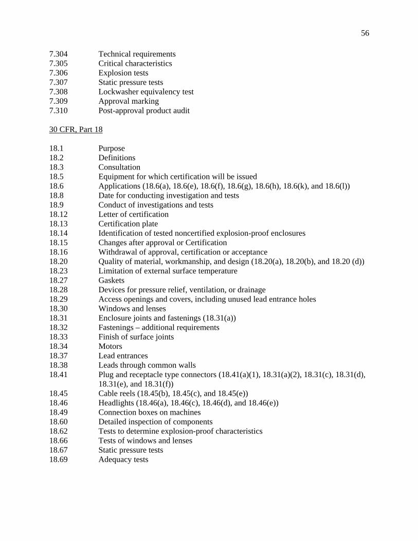
56
7.304 Technical requirements 7.305 Critical characteristics 7.306 Explosion tests 7.307 Static pressure tests 7.308 Lockwasher equivalency test 7.309 Approval marking 7.310 Post-approval product audit 30 CFR, Part 18 18.1 Purpose 18.2 Definitions 18.3 Consultation 18.5 Equipment for which certification will be issued 18.6 Applications (18.6(a), 18.6(e), 18.6(f), 18.6(g), 18.6(h), 18.6(k), and 18.6(l)) 18.8 Date for conducting investigation and tests 18.9 Conduct of investigations and tests 18.12 Letter of certification 18.13 Certification plate 18.14 Identification of tested noncertified explosion-proof enclosures 18.15 Changes after approval or Certification 18.16 Withdrawal of approval, certification or acceptance 18.20 Quality of material, workmanship, and design (18.20(a), 18.20(b), and 18.20 (d)) 18.23 Limitation of external surface temperature 18.27 Gaskets 18.28 Devices for pressure relief, ventilation, or drainage 18.29 Access openings and covers, including unused lead entrance holes 18.30 Windows and lenses 18.31 Enclosure joints and fastenings (18.31(a)) 18.32 Fastenings – additional requirements 18.33 Finish of surface joints 18.34 Motors 18.37 Lead entrances 18.38 Leads through common walls 18.41 Plug and receptacle type connectors (18.41(a)(1), 18.31(a)(2), 18.31(c), 18.31(d),
18.31(e), and 18.31(f)) 18.45 Cable reels (18.45(b), 18.45(c), and 18.45(e)) 18.46 Headlights (18.46(a), 18.46(c), 18.46(d), and 18.46(e)) 18.49 Connection boxes on machines 18.60 Detailed inspection of components 18.62 Tests to determine explosion-proof characteristics 18.66 Tests of windows and lenses 18.67 Static pressure tests 18.69 Adequacy tests

57
APPENDIX 2
Summary of Selected Explosion-proof Enclosure Clauses, According to Relevant IEC Requirements Contained in IEC
Publications 600079-0 and 600079-1 The International Electrotechnical Commission (IEC) prepares international recommendations and standards for construction and use of electrical apparatus. Many industrialized nations adopt IEC standards, and it is common practice for developing nations to pattern their standards after IEC standards. This Appendix lists the clauses of the IEC standards concerning the design, construction, and testing requirements identified in the IEC standards for explosion-proof (flameproof) enclosures pertaining to Group I (mining) applications. The following clauses in the IEC documents were considered as relevant for the equivalency review of the IEC standards compared to MSHA’s requirements for explosion-proof enclosures. IEC 60079-0, Forth Edition, 2004-01 Clause Title 1 Scope 2 Normative references 3 Terms and definitions (3.1, 3.4, 3.5.1 to 3.5.4, 3.7, 3.8, 3.11, 3.13 3.14, 3.15, 3.16,
3.18, 3.19, 3.22 3.23, 3.24, 3.25, 3.26) 4 Apparatus grouping and temperature classification (4.1 – Group I) 5 Temperatures (5.1.1, 5.2, 5.3.1, 5.3.2.1, 5.4) 6 Requirements for all apparatus (6.1, 6.2, 6.5) 7 Non-metallic enclosures and non-metallic parts of enclosures (7.1 to 7.4) 8 Enclosures containing light metals (8.1.1, 8.2) 9 Fasteners (9.1 to 9.3) 10 Interlocking devices 11 Bushings 12 Materials used for cementing 13 Ex components 13.1 to 13.3) 14 Connection facilities and terminal compartments (14.1, 14.3) 16 Entries into enclosures (16.1 to 16.4) 17 Supplementary requirements for rotating electrical machines (17.1 to 17.5)

58
20 Supplementary requirements for plugs and sockets (20.1, 20.2) 21 Supplementary requirements for luminaries (21.1 to 21.3) 24 Documentation 25 Compliance of prototype or sample with documents 26 Type tests (26.1, 26.2, 26.3, 26.4.1.1, 26.4.1.2, 26.4.1.2.1, 26.4.2, 26.4.3, 26.4.4,
26.5.1, 26.5.2, 26.6.1, 26.6.2, 26.7.1, 26.7.2, 26.8, 26.9, 26.10.1 to 26.10.3, 26.11, 26.13, 26.14.1 to 26.14.7, 26.15.1, 26.15.2)
27 Routine verifications and tests 28 Manufacturer’s responsibility (28.1 to 28.2) 29 Marking (29.1 to 29.8, 29.10) 30 Instructions (30.1) Annex A Cable Glands Annex B Requirements for Ex components Annex C Example of rig for resistance to impact test IEC 60079-1, Fifth Edition, 2003-11 Clause Title 1 Scope 2 Normative references 3 Terms and definitions (3.1 to 3.17) 4 Apparatus grouping and temperature classification 5 Flameproof joints (5.1, 5.2, Table 1 – Group I, 5.3, Table 3, Table 4, 5.4, 5.5) 6 Cemented Joints (6.1 to 6.3) 7 Operating rods (7.1, 7.2) 8 Supplementary requirements for shafts and bearings (8.1, 8.2) 9 Light transmitting parts 10 Breathing and draining devices which form part of a flameproof enclosure
(10.1 to 10.9) 11 Fasteners, associated holes and closing devices (11.1 to 11.10) 12 Materials and mechanical strength of enclosures – Materials inside the enclosures
(12.1 to 12.6) 13 Entries for flameproof enclosures (13.1, 13.2.1, 13.3, 13.4) 14 Verifications and tests 15 Type tests (15.1 – Group I, 15.2 – Group I, 15.4.1 to 15.4.3) 16 Routine tests (16.1 to 16.3) 19 Non-metallic enclosures and non-metallic parts of enclosures (19.1 to 19.3) Annex A Additional requirements for crimped ribbon elements of breathing and draining
devices Annex B Additional requirements for elements, with non-measurable paths, of breathing
and draining devices Annex C Additional requirements for flameproof cable glands, Ex blanking elements, and
Ex thread adapters Annex D Empty flameproof enclosures as Ex components

59
APPENDIX 3
SUMMARY OF DESIGN REQUIREMENTS -- MSHA REGULATIONS AND IEC STANDARDS FOR SELECTED FEATURES OF EXPLOSION-PROOF (FLAMEFROOF) ELECTRICAL ENCLOSURES
FEATURE MSHA IEC SUMMARY OVERVIEW
RUGGEDNESS
(Strength, Suitability, etc.)
Design Specifications Explosion Tests Optional Static Pressure Tests
Impact/Drop Tests Explosion Tests (Reference Pressure) Static or Dynamic Pressure Tests
MSHA: Cites minimum design thicknesses for enclosure walls, flanges, and covers to withstand internal pressures of 150 psig. Smaller thicknesses are permitted for potted components and for enclosures having reinforcing ribs or design features that provide equivalent strength. Static pressure tests, if required, are performed at 150 psig or 1.5 times the maximum explosion pressure observed, whichever is greater. Static pressure tests are required for every explosion-proof enclosure housing high-voltage switchgear, unless the manufacturer uses an MSHA accepted quality assurance procedure covering welding and inspection of the enclosures. IEC: Requires mechanical (impact, drop and thermal shock) tests of sample or prototype to ensure strength is adequate. Each prototype enclosure must withstand internal pressures of at least 3.5 bar (51 psig) or a pressure of at least 1.5 times the “reference” pressure, whichever is greater. A “reference” pressure is determined by conducting explosion tests using a 9.8% methane-air mixture inside the enclosure. Each manufactured unit is subject to “routine” testing. Such testing requires the enclosure to be pressure tested at 1.5 times the maximum “reference” explosion pressure observed; otherwise, the prototype must be static or dynamic pressure tested at 4 (four) times the maximum “reference” explosion pressure observed. This static or dynamic pressure must be at least 4 x 51 psig = 204 psig. When the “reference” pressure determination is impractical, the applied pressure is to be 10 bar (145 psig). The “reference” pressure tests are considered satisfactory if the enclosure suffers no permanent deformation or damage affecting the explosion-proof (flameproof) integrity and the flamepath joints are not permanently enlarged. “Routine” tests are required for enclosures with welded construction. Impact tests are performed with impact energies ranging from 7 or 20 Joules, depending on the perceived risk of mechanical danger.

60
FEATURE MSHA IEC SUMMARY OVERVIEW
FASTENERS
(Bolts, Screws, Studs, etc.)
Design Specifications
Design Specifications Explosion Tests (Reference Pressure) Static or Dynamic Pressure Tests
MSHA: Acceptable minimum sizes and maximum spacings of fasteners specified. Lockwashers or equivalent devices are required to prevent loosening on all fastenings used to secure essential parts of an enclosure. IEC: Minimal design specifications cited -- size and adequacy determined essentially through performance tests used to assess ruggedness. Means to prevent loosening by vibration are only required where necessary. A tool is required for removing fasteners. Shrouding or counter-bored holes in covers are required for fasteners.
FLAME PATHS
(Plane, Cylindrical, Step Joints, etc.)
Design Specifications Explosion Tests
Design Specifications Flame Propagation Tests
MSHA: Provides detailed flamepath length and gap dimensions based on enclosure volume (three categories). In general, the flamepath gaps are too small to permit the passage of flame during explosion tests (i.e., 0.004 in for the maximum allowable flange joint gap – all in one plane). MSHA does not permit intentional gaps between flanged surfaces. MSHA does not permit the use of gaskets except under special circumstances (e.g. windows/lenses). MSHA has specific criteria regarding the measurable flamepath width, as that before and after an o-ring. IEC: Provides detailed flame path length and gap dimensions based on enclosure volume (four categories). In general, the IEC permits larger flamepath gaps than MSHA (maximum allowable flange joint gap -- joint all in one plane: MSHA 0.10 mm, IEC 0.50 mm;) therefore, glowing gases may be sighted from IEC specified flame paths. IEC does not permit intentional gaps between flanged surfaces, except those gaps necessary for quick acting doors or covers. The IEC permits the use of gaskets and o-rings as long as they are positioned outside of a flamepath.

61
FEATURE MSHA IEC SUMMARY OVERVIEW LEAD ENTRANCES
(Lead Entrances, Insulated Studs, Bushings, etc.)
Design Specifications Explosion Tests
Design Specifications Static or Dynamic Pressure Tests, if applicable Clamping and Mechanical Strength Tests
MSHA: Specifies design requirements for lead entrances (packing glands) using rope-like packing materials, as well as, those using sealing rings (grommets). Requires special explosion tests for non-asbestos rope-like packing materials, fiber optic cables assemblies and small electrical connectors. Requires flame-resistant cables or cables enclosed in flame-resistant hose conduit. Flexible or threaded rigid metal conduit and fittings are not acceptable. IEC: Permits cable entries using an elastomeric sealing ring; hard setting resin; or, a metallic sealing ring (in the case of metal sheathed cable). Requires torque tests for bushings and terminal studs, insulation resistance tests of plastic parts, and the routine flame transmission test using hydrogen/methane fuel. Cable entries must pass clamping tests. Use of “Increased Safety” terminal enclosures (connection boxes) is optional.
WINDOWS and LENSES
Design Specifications Thermal Shock Tests Drop Weight (Impact) Tests Explosion Tests
Thermal Shock Tests Drop Weight Tests Flame Propagation Tests Explosion Tests (Reference Pressure) Static or Dynamic Pressure Tests
MSHA: Special mounting requirements for windows and lenses are required to facilitate inspection. Impact energy ranges from 2.7 to 10.8 Joules, depending on the size of the window or lens. Thermal shock tests performed by immersion of the window or lens in its mounting heated to 150 °C into water at a temperature between 15 °C and 20 °C. Explosion tests are then performed using each sample tested. IEC: Impact energy ranges from 4 to 7 joules, depending on the degree of perceived risk from mechanical damage. Thermal shock tests performed by spraying a jet of water about 1 mm in diameter at a temperature of 10° ± 5 °C onto the window or lens at its maximum service temperature.

62
FEATURE MSHA IEC SUMMARY OVERVIEW BREATHERS and
DRAINS Design Specifications Explosion Tests
Design Specifications Flame Propagation Tests Explosion Tests (Reference Pressure) Static or Dynamic Pressure Tests Thermal Tests
MSHA: Devices for pressure relief, ventilation or drainage are acceptable provided the length of the flame arresting path and the clearances or size of holes in perforated metal will prevent the discharge of flame in explosion tests. Such devices must be made of materials that will resist corrosion and distortion, and be designed so that they may be cleaned readily. IEC: Breathing and draining devices are allowed "...if required for technical reasons...” They should be constructed that they are not liable to become inoperable in service, due to the accumulation of dust, paint, etc. Breathing and draining devices which form part of a flameproof enclosure must incorporate permeable elements (sintered metal, pressed wire, or metal foam) which can withstand the pressure created by an internal explosion in the enclosure to which they are fitted. They also must prevent the transmission of the explosion to the explosive atmosphere surrounding the enclosure. Passage of hot glowing gases is permitted during flame propagation tests. There are special requirements and tests defined for the devices with elements with measurable and non-measurable paths and for devices with crimped ribbon elements.
SURFACE TEMPERATURE
Surface Temperature Tests
Surface Temperature Tests
MSHA: 150 °C for the external surfaces of any enclosure and 115 °C internal temperature for enclosures housing polycarbonate windows or lenses. Headlight enclosures and other heat producing enclosures are tested at their maximum electrical ratings under laboratory conditions.
IEC: 150 °C for the external surfaces where combustible dust can form a layer for Group I enclosures and 450 °C on surfaces where combustible dust cannot form a layer. In general, the tests are conducted with the most adverse conditions at the most unfavorable voltage between 90% and 110% of the rated voltage of the equipment. The results are corrected for the maximum ambient temperature specified in the rating.
The IEC standards have temperature limitations for non-metallic enclosures and non-metallic parts of enclosures, as determined for the type of material.

63
FEATURE MSHA IEC SUMMARY OVERVIEW
EXPLOSION TESTING
(Flame Propagation
Testing, etc.)
Explosion Tests
Flame Propagation
Tests
MSHA: Checks for non-transmission of an internal ignition by setting conditions to produce the highest explosion pressures (i.e., varying ignition and pressure reading locations and conducting some tests with internal components removed) and observing for glowing gases or external ignition of the surrounding methane-air mixture and for the presence of afterburning. Tests are conducted with all o-rings removed and flamepath lengths and gaps within manufacturing tolerances. Some tests conducted with coal dust added to the methane-air mixture (6.7% to 9.8%) within the enclosure to color the "flame". Explosion tests of the enclosure must not result in: discharge of flame from the enclosure; ignition of an explosive mixture surrounding the enclosure; development of afterburning; rupture of any part of the enclosure or any panel or divider within the enclosure; and, permanent distortion of the enclosure exceeding 0.040 inch (1.016 m ) per linear foot. Special explosion tests are conducted for enclosures that share leads through a common wall between the enclosures. Such testing is performed to determine if pressure piling conditions would develop if one or more of the isolating barriers, sectionalizing terminals, etc. are removed. IEC: Checks for non-transmission of an internal ignition by use of a special 12% flammable mixture (42% hydrogen, 58% methane) and observing for external ignition of the surrounding hydrogen/methane-air mixture. Tests are conducted with all gaskets removed and with enlarged gaps and reduced flamepath lengths. Tests are considered satisfactory if the ignition inside of the enclosure is not transmitted to the test chamber. The IEC standards do not address the removal of insulating bushings in a common wall between enclosures during explosion testing to assess the effects of pressure piling.
Related Documents