Page 1 of 22 All testing and sample preparation for this report was performed under the continuous, direct supervision of IAPMO R&T Lab, unless otherwise stated. The statement of compliance is based on the test results compared to the standard specifications without considering measurement uncertainty. The observations, test results and conclusions in this report apply only to the specific samples tested and are not indicative of the quality or performance of similar or identical products. Only the Client shown above is authorized to copy or distribute the report, and then only in its entirety. If presented with a copy of a Test Report without the IAPMO R&T Lab watermark background, contact IAPMO R&T Lab for verification. Any use of the IAPMO R&T Lab name for the sale or advertisement of the tested material, product or service is prohibited absent the advance written consent of IAPMO R&T Lab. Report Number: 1757-21033 Project Number: 36703 Report Issued: September 2 nd , 2021 Client: Schier Products 6455 Woodland Dr. Shawnee, KS 66218 Contact: Charlie Ismert Source of Samples: Samples were manufactured at the client’s facility in Shawnee, KS and was witnessed tested by Dale E. Holloway of IAPMO R&T Lab on August 23 rd , 2021. Samples are manufactured in good condition. Date of Testing: August 23 rd , 2021 through September 1 st , 2021 Sample Description: HDPE Grease Interceptor. Model: GB-1000 (100 gpm) Refer to the manufacturer’s drawings and installation instructions for more detailed measurements and information. Scope of Testing: The above grease interceptor was witnessed tested to meet the requirements of ASME A112.14.3-2018 “Hydromechanical Grease Interceptors”, and CSA B481.0 and B481.1-12 “Grease Interceptors”. Conclusion: The GB-1000 (100 gpm) Grease Interceptor DID COMPLY with the requirements of ASME A112.14.3-2018 “Hydromechanical Grease Interceptors” and CSA B481.0 and B481.1-12 “Grease Interceptors”. By the signature below, I certify that all the testing and preparation for this report was performed under direct supervision of IAPMO R&T Lab, unless otherwise stated. Witness tested and reported by, Dale E. Holloway, Regional Technical Manager IAPMO R&T Lab

Welcome message from author
This document is posted to help you gain knowledge. Please leave a comment to let me know what you think about it! Share it to your friends and learn new things together.
Transcript
Page 1 of 22
All testing and sample preparation for this report was performed under the continuous, direct supervision of IAPMO R&T Lab, unless otherwise stated. The statement of compliance is based on the test results compared to the standard specifications without considering measurement uncertainty. The observations, test results and conclusions in this report apply only to the specific samples tested and are not indicative of the quality or performance of similar or identical products. Only the Client shown above is authorized to copy or distribute the report, and then only in its entirety. If presented with a copy of a Test Report without the IAPMO R&T Lab watermark background, contact
IAPMO R&T Lab for verification. Any use of the IAPMO R&T Lab name for the sale or advertisement of the tested material, product or service is prohibited absent the advance written consent of IAPMO R&T Lab.
Report Number: 1757-21033 Project Number: 36703 Report Issued: September 2nd, 2021 Client: Schier Products 6455 Woodland Dr. Shawnee, KS 66218 Contact: Charlie Ismert Source of Samples: Samples were manufactured at the client’s facility in Shawnee, KS and
was witnessed tested by Dale E. Holloway of IAPMO R&T Lab on August 23rd, 2021. Samples are manufactured in good condition.
Date of Testing: August 23rd, 2021 through September 1st, 2021 Sample Description: HDPE Grease Interceptor. Model: GB-1000 (100 gpm) Refer to the manufacturer’s drawings and installation instructions for more
detailed measurements and information. Scope of Testing: The above grease interceptor was witnessed tested to meet the
requirements of ASME A112.14.3-2018 “Hydromechanical Grease Interceptors”, and CSA B481.0 and B481.1-12 “Grease Interceptors”.
Conclusion: The GB-1000 (100 gpm) Grease Interceptor DID COMPLY with the
requirements of ASME A112.14.3-2018 “Hydromechanical Grease Interceptors” and CSA B481.0 and B481.1-12 “Grease Interceptors”.
By the signature below, I certify that all the testing and preparation for this report was performed under direct supervision of IAPMO R&T Lab, unless otherwise stated. Witness tested and reported by,
Dale E. Holloway, Regional Technical Manager IAPMO R&T Lab
Report No. 1757-21033 Page 2 of 22
Primary Standards: ASME A112.14.3-2018 2 General Requirements 4 Labeling, Installation, and Maint. 2.1 Rating 4.1 Labeling 2.2 Inlet and Outlet Connections 4.2 Installation Components 2.3 Flow Controls and/or Vents 4.3 Maintenance and Cleaning Instructions 3 Testing 3.1 Construction of Test Equipment 3.2 Installation of Testing Equipment 3.3 Preliminary Test Procedure 3.4 Rating Test Procedure 3.5 Skimming Procedure
CSA B481.0-12 4. Material Requirements 5. Construction Requirements 6. Test Methods and Performance Requirements 7. Markings
CSA B481.1-12 4. General Requirements 5. Test Method 6. Markings
Test Results: All test and evaluations were conducted per the written procedures in the specific standards.
ASME A112.14.3-2018 2 General Requirements: 2.1 Rating: COMPLIES
The flow rate and grease retention capacity of each grease interceptor was determined by application of the parameter of this Standard. The unit tested was a “Type D” - Units without an external flow control, indirectly connected.
2.2 Inlet and Outlet Connections: COMPLIES Inlet and Outlet connections - Hubless coupling is compliant with ASTM A888 2.3 Flow Controls and/or Vents: NOT APPLICABLE 2.3.1 Flow control and Vents or air intakes were not used.
2.3.2 When a flow control and/or vent is used during testing for rating a grease interceptor, the
rating of the unit did not exceed the maximum flow through the flow control.
The manufacturer’s literature reflected that the rating was achieved with the flow control and vent attached, and that the flow control and vent was installed with the unit.

Report No. 1757-21033 Page 3 of 22
Testing
3.1 Construction of Test Equipment: 3.1.1 Test Sink: COMPLIES
Length - 8’ (8 ft) Width - 2’ (2 ft) Depth - 12.5” (12.5 inches) Corrosion Resistant Material - stainless steel (yes) Number of compartments - 2 (2) Structurally reinforced - yes (yes) Supported on legs - yes (yes) Rim height with legs - 3’ (3 ft) Legs structurally supported - yes (yes)
3.1.1.1 Sink Waste Connections: COMPLIES
Each sink compartment was fitted with a 1-½” (up to 50 gpm) or 2” (greater than 50 gpm) standard sink waste connection with flange, crossbars, slip joint tailpiece, and locknut. The waste connections were located on opposite sides of the center partition in the corner formed by the side of the sink and the center partition.
3.1.1.2 Water Level Gauges: COMPLIES Each compartment was equipped with a gauge connection and a water level gauge with gauge glass. Each gauge connection was fitted into the bottom of a sink compartment and in close proximity to the waste outlet. Each gauge was mounted on the outside of the sink, adjacent to its respective gauge connection, and extended diagonally upward from the bottom center to the top outside corners. The gauges were calibrated to read directly the number of inches of water in the sink compartments above the sink waste flange.
3.1.1.3 Movable Sink Partitions: COMPLIES
Each compartment of the sink was fitted with a movable partition, making it possible to regulate the size of the compartment to any desired capacity.
Report No. 1757-21033 Page 4 of 22
3.1.2 Skimming Tank: COMPLIES The skimming tank was rectangular in shape and open at the top.
Tank Length - 12’ Tank Width - 36” _ Tank Depth - 28” _ Tank was made of corrosion resistant material - yes (yes) Tank was structurally reinforced - yes (yes) Waste outlet diameter - 4” (4 inches)
The waste outlet was connected to the bottom of the tank at one end and trapped to retain approximately 18 inches of water in the tank. The tank provided a stationary baffle located approximately 4 ft. from the end of the tank receiving the discharge from the interceptor. This baffle extended the width of the tank and to within 4” of the bottom of the tank.
3.2 Installation of Testing Equipment: 3.2.1 Direct Connection Test Types A, B, and C: NOT APPLICABLE 3.2.2 Indirect Connection Test Type D:
Findings- The “GB-1000” was a Type D unit.
3.2.2.1 Sink and Interceptor Locations: COMPLIES The sink was located on the floor with the sink rim 3 ft above the floor level and 13 feet above the outside bottom of the grease interceptor being tested.
3.2.2.2 Floor Sink and Location: COMPLIED A 6 in. deep floor sink to receive the indirect waste discharge from the test sink shall be
located in the floor supporting the test sink. The rim of the floor sink shall be located at floor level. The outlet of the floor sink shall be sized to handle the test flow rate, and shall not be less than 3 in.
3.2.2.3 Skimming Tank Location: COMPLIES
The skimming tank was located low enough, with respect to the interceptor, for the discharge piping from the interceptor to clear the tank rim by not less than 3 inches.
3.2.2.4 Installation of Waste Piping: COMPLIES (a) Sink Connections- The sink outlet waste connection from each sink compartment
was 1-½ inches in size and fitted with a quarter-turn ball quick-opening valve. (b) Combined Horizontal Waste Piping- The combined horizontal waste piping into
which the sink outlets connect shall be 3”, installed with the center line 11 inches below the bottom of the sink and properly hung and braced from the sink reinforcement and supports. The waste pipe shall connect to a *single 3” valve that shall serve to regulate the total discharge flow rate. The pipe connected to the valve outlet shall turn downward 90 deg and shall terminate 1” above the rim and at the centerline of the floor sink. *Due to the 200 gpm rating, for a Type “D” configuration of the Standard (Figure 3), it calls for a 3” waste valve for the sink to regulate flow from that sink. Since two sinks were used in tandem to achieve the 200 gpm, an additional 3” valve was used on the second sink. Approved by IAPMO R&T review engineer.

Report No. 1757-21033 Page 5 of 22
(c) Floor Sink to Interceptor Piping- A trap fitting shall be connected to the outlet of the
floor sink, of a size appropriate for the flow rate tested, but not less than 3”. Horizontal piping of the same size and 3 ft in length with a vent shall be connected between the floor sink elbow and the vertical waste riser, which shall extend downward to connect to the grease interceptor inlet by means of an elbow and a short horizontal nipple.
(d) Interceptor Discharge- The discharge pipe from the grease interceptor outlet to the skimming tank shall be the same size as the inlet pipe. It shall have a minimum pitch of 1/8”/ft and shall be provided with a 2” vent properly located to prevent siphoning of the interceptor.
(e) Interceptor Inlet Connection- If the inlet and or outlet connections of the interceptor are larger than the inlet pipe necessary to provide the required flow rate, reducing couplings shall be permitted to be used.
3.3 Preliminary Test Procedure: 3.3.1 Media Analysis: COMPLIES
pH of water - 6.4 (6.0 to 8.0) Specific Gravity of Lard - 0.875 at 150°F (0.875 ± 0.005 at 150°F) Viscosity in Seconds Saybolt Universal @ 150°F
3.3.2 Establishing Sink Compartment Capacity: COMPLIES Capacity of compartment 1- 120 gallons (1.2 x flow rate of interceptor) Capacity of compartment 2- 120 gallons (1.2 x flow rate of interceptor)
3.3.3 Establishing Vol. of Incremental Discharge: (based on 10” water above sink outlet): COMPLIES Compartment 1 Discharge - 100 gallons (equal to flow rate of interceptor) Compartment 2 Discharge - 100 gallons (equal to flow rate of interceptor)
3.3.4 Computation of Flow Rate: FOLLOWED The flow rate from the sink was computed by timing the rate of drainage of the first 9 ½” of water from the sink compartment, measured from the 10” mark to the datum line ½” above the sink outlet flange.
Report No. 1757-21033 Page 6 of 22
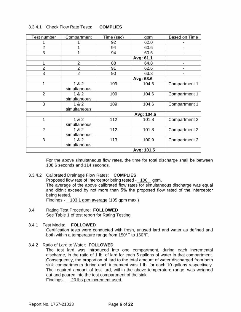
3.3.4.1 Check Flow Rate Tests: COMPLIES
Test number Compartment Time (sec) gpm Based on Time
1 1 92 62.0 -
2 1 94 60.6 -
3 1 94 60.6 -
Avg: 61.1
1 2 88 64.8 -
2 2 91 62.6 -
3 2 90 63.3 -
Avg: 63.6
1 1 & 2 simultaneous
109 104.6 Compartment 1
2 1 & 2 simultaneous
109 104.6 Compartment 1
3 1 & 2 simultaneous
109 104.6 Compartment 1
Avg: 104.6
1 1 & 2 simultaneous
112 101.8 Compartment 2
2 1 & 2 simultaneous
112 101.8 Compartment 2
3 1 & 2 simultaneous
113 100.9 Compartment 2
Avg: 101.5
For the above simultaneous flow rates, the time for total discharge shall be between 108.6 seconds and 114 seconds.
3.3.4.2 Calibrated Drainage Flow Rates: COMPLIES Proposed flow rate of Interceptor being tested - 100 gpm. The average of the above calibrated flow rates for simultaneous discharge was equal and didn’t exceed by not more than 5% the proposed flow rated of the interceptor being tested.
Findings - 103.1 gpm average (105 gpm max.) 3.4 Rating Test Procedure: FOLLOWED See Table 1 of test report for Rating Testing. 3.4.1 Test Media: FOLLOWED
Certification tests were conducted with fresh, unused lard and water as defined and both within a temperature range from 150°F to 160°F.
3.4.2 Ratio of Lard to Water: FOLLOWED The test lard was introduced into one compartment, during each incremental discharge, in the ratio of 1 lb. of lard for each 5 gallons of water in that compartment. Consequently, the proportion of lard to the total amount of water discharged from both sink compartments during each increment was 1 lb. for each 10 gallons respectively. The required amount of test lard, within the above temperature range, was weighed out and poured into the test compartment of the sink. Findings- __ 20 lbs per increment used.
Report No. 1757-21033 Page 7 of 22
3.4.3 Test Increments: FOLLOWED
Each test increment consisted of the simultaneous discharge of water from both sink compartments and the lard from the test compartment.
During the first test increment, the lard was poured into compartment 1 while compartment 2 discharged clear water. During the second test increment the lard was poured into compartment 2 while the water in compartment 1 remained clear.
3.4.4 Flow Rates: FOLLOWED
The drainage period for each increment was gauged and timed on the basis of the flow from the compartment containing the clear water. The flow rate from the sink was computed and recorded for each increment. (See Table 1 of test report).
3.4.5 Efficiency Determinations (Minimum Grease Capacity): NOT USED At the option of the manufacturer the efficiency determination was conducted at the interceptor’s minimum grease capacity per Table 1 or at the interceptor’s maximum grease capacity by determining the break down point.
3.4.6 Efficiency Determinations (Maximum Grease Capacity): FOLLOWED The grease was removed from the skimming tank and the efficiency of the interceptor was computed at intervals of five increments or less until the average efficiency reached 93% or less and/or the incremental efficiency reached 85% or less (See Table 1 of test report).
3.4.6.1 Duration of the Test: FOLLOWED The testing was continued until the average efficiency reached 85% or less and/or the incremental efficiency reached 75% or less.
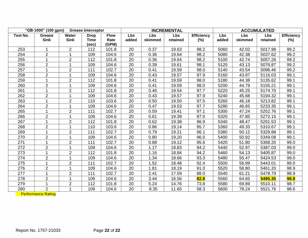
3.4.6.2 Determination of Test Breakdown Grease Capacity: FOLLOWED Maximum grease retention capacity was established at the increment preceding two successive increments in which either the average efficiency is less than 90% or the incremental efficiency is less than 80 %.
3.4.7 Efficiency Determinations (Minimum Grease Capacity): NOT USED 3.4.8 Performance Requirements for Certification: COMPLIES
The interceptor did conform with or exceeded the following requirements at the breakdown point: (a) Had an average efficiency of 90% or more.
Findings – 98.8 %
(b) Had an incremental efficiency of 80% or more. Findings – 82.8 %
(c) Had retained not less than 2 lbs of grease for each 1 gpm average flow rate as determined during the testing.
Findings – 5495.35 lbs.
Report No. 1757-21033 Page 8 of 22
3.4.9 Rated Capacities: COMPLIES Standard rating flow rate and grease retention capacities for grease interceptors were tested in accordance with the above test procedure and did conform with the requirement of ASME A112.14.3-2018. Findings- Flow Rate 100 gpm Grease Retention Capacity Rating - 200 lbs. Actual Grease Retention Capacity - 5495.35 lbs.
3.5 Skimming Procedure: FOLLOWED
The skimming procedure was initiated 5 minutes after the increment to be skimmed has discharged into the tank. The baffles were used alternately until the amounts of grease collected in the procedure are less than 1% by visual observation. Upon completion of the skimming procedure, water shall be drained from the bottom of the pail by means of a spigot. The remainder of the water was collected as describe in the procedure until only a few drops are observed. The lard is then weighed to the nearest ½ gram.
4 Labeling, Installation, and Maintenance 4.1 Labeling: COMPLIES Products were labeled with the following information:
(a) Manufacturer’s name - Schier Products (yes) (b) Model number - GB-1000 (yes) (c) Rated flow(s) - yes (yes) (d) “Inlet” and “Outlet” - yes (yes) (e) ASME A112.14.3 - yes (yes) (f) Efficiency at the minimum grease capacity - yes (yes) (g) If appropriate, flow control model number and or orifice size - __NA_____
4.2 Installation Components: COMPLIES
The grease interceptor was provided with complete installation instructions, including but not limited to the following: (a) Flow control and/or vent requirements - yes (yes) (b) Separate trapping requirements - yes (yes) (c) Elevation and accessibility requirements - yes (yes) (d) Safety and health-related instructions - yes (yes) (e) Cleanout locations - yes (yes) (f) Instructions that show the clearances required for maintenance, cleaning, and
hazard prevention - yes (yes) (g) Cautions against installation in any manner except as tested and rated- yes
(yes) (h) Where a reducer is required on the outlet, it shall be eccentric with the flat on the
bottom- _NA___ 4.3 Maintenance and Cleaning Instructions: COMPLIES
Units were provided with complete maintenance instructions including but not limited to the following: (a) Maintenance Instructions - yes (yes) (b) Safety and health provisions - yes (yes) (c) Cleaning instructions - _________ ______yes__ (yes)
Each grease interceptor was provided with service instructions and cleaning instructions which included a trouble-shooting guide as well as instructions for performing necessary servicing or for obtaining servicing.

Report No. 1757-21033 Page 9 of 22
See actual test data for ASME A112.14.3-2018 at the end of this report
CSA B481.0-12
4. Material Requirements 4.1 Mild Steel: NOT APPLICABLE 4.2 Stainless Steel: NOT APPLICABLE 4.3 Thermoplastics: COMPLIED
Thermoplastics used for the construction of the body of the grease interceptor shall comply with the material requirements specified in CSA B181.3 and shall have a minimum wall thickness of 0.156”. (See Section 5.3) Findings: Thickness- ___0.375”_______
4.4 Fiberglass-reinforced plastic NOT APPLICABLE 4.5 Concrete: NOT APPLICABLE 4.6 Covers: COMPLIES
Grease interceptor covers shall be made of metal, plastic, or concrete meeting the requirements of Clauses 4.1 to 4.5 and shall comply with the load requirements of Clause 6.1. Findings: Covers are made from either Cast Iron or fiberglass/plastic composite.
4.7 Galvanic corrosion: NOT APPLICABLE
Where dissimilar metals are connected, materials shall be chosen such that galvanic corrosion is minimized.
4.8 Fasteners: NOT APPLICABLE 5. Construction Requirements 5.1 General: COMPLIED Grease Interceptors Shall: _X_ (a) be constructed to perform at the maximum flow rate for which they are
designed. _X_ (b) have a minimum FOG containment volume capacity of 25% of the flow
rating of the interceptor. _X_ (c) have a minimum solids containment capacity of 25% of the flow rating of
the interceptor, if designed to contain solids. _X_ (d) be constructed to withstand a hydrostatic water column of 36 mm H2O
(1.5 inches H2O) above the cover seal of the interceptor applied for 15 min. as described in Clause 6.3.
_X_ (e) have inlet and outlet connection as follows: (i) Threaded connections shall comply with ASME B1.20.1
(ii) Hub or hubless connections shall comply with the dimensional
requirements of an applicable Standard for the material used.
(iii) Other connections shall comply with the National Plumbing Code
of Canada or applicable provincial plumbing code requirements.
_X_ (f) have a means to prevent siphoning.

Report No. 1757-21033 Page 10 of 22
_NA_ (g) be protected against galvanic corrosion if dissimilar metallic materials are used in their construction.
_X_ (h) have a removable cover. _X_ (i) have adequate access for:
(i) Proper cleaning and removal of FOG and sediments, allowing, at
a minimum, access by a 50 mm (2in) diameter vacuum hose.
(ii) Personnel to reach removable internal components.
_X_ (j) be free of defects that could affect appearance, serviceability, containment, and performance.
5.2 Mild Steel: NOT APPLICABLE 5.3 Thermoplastics: 5.3.1 General requirements: COMPLIED Thermoplastics shall have:
(a) Have a tensile yield strength greater than 2320 psi - __3,224 psi____
(b) Be UV stabilized- __Pass______
5.3.2 Specific requirements: COMPLIED The following requirements shall also apply to thermoplastics:
(a) Blow-moulded shall have a specific gravity greater than 0.945 - ___ NA____
(b) Injection moulded shall have a specific gravity greater than 0.935 – _NA ___
(c) Rotationally moulded thermoplastics shall have a specific gravity
greater than 0.935 - _0.947_______ (d) Butt-welded shall have
(i) A specific gravity greater than 0.945 - ___________NA_____
(ii) A modulus of elasticity greater than 232,060 psi - __NA_____
(iii) An Izod impact of 1.78 lbf/ft/in at 23 degrees C. - __NA______
5.4 Fiberglass-reinforced plastic: NOT APPLICABLE 5.5 Concrete Coatings and Linings: NOT APPLICABLE 5.6 Flow Control Devices: COMPLIED
Flow control devices, if required by the manufacturer, shall be integral to the system and shall be constructed in such a way that they cannot be readily removed, disassembled, or tampered with.
5.7 Load Design for Buried Grease Interceptors: COMPLIED 5.7.1 General Load Requirements:
Buried grease interceptors shall be designed to withstand all anticipated earth loads, including vertical and lateral soil loads and loads due to groundwater hydrostatic pressure, buoyancy, and live traffic. This requirement shall not apply to in-floor applications.
5.7.2 Minimum Load Requirements: When the buried depth is
_X_ (a) 0.9 m (3 ft) or less, buried grease interceptors shall be designed for an earth load of at least 40 kPa (5.8 psi).
___ (b) greater than 0.9 m (3 ft) but less than 1.8 m (6 ft), buried grease interceptors shall be designed for an earth load of at least 90 kPa (13 psi).
Report No. 1757-21033 Page 11 of 22
___ (c) greater than 1.8 m (6 ft), grease interceptor installations shall be certified by a professional engineer.
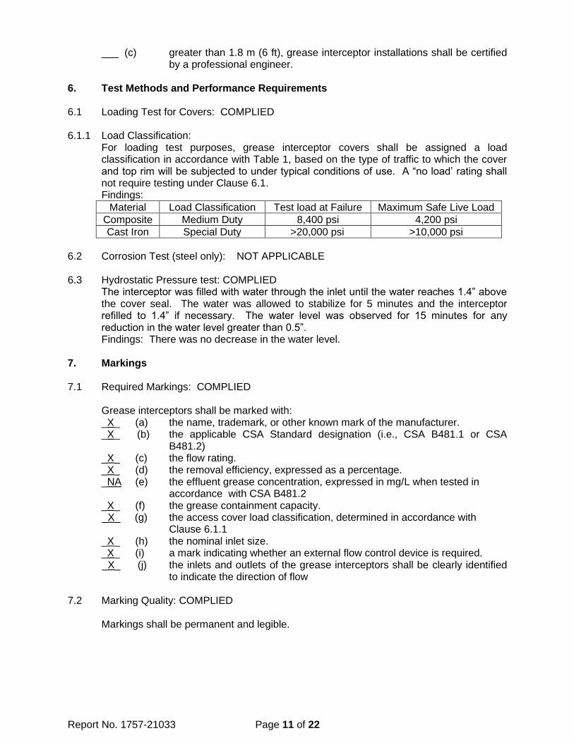
6. Test Methods and Performance Requirements 6.1 Loading Test for Covers: COMPLIED 6.1.1 Load Classification:
For loading test purposes, grease interceptor covers shall be assigned a load classification in accordance with Table 1, based on the type of traffic to which the cover and top rim will be subjected to under typical conditions of use. A “no load’ rating shall not require testing under Clause 6.1. Findings:
Material Load Classification Test load at Failure Maximum Safe Live Load
Composite Medium Duty 8,400 psi 4,200 psi
Cast Iron Special Duty >20,000 psi >10,000 psi
6.2 Corrosion Test (steel only): NOT APPLICABLE 6.3 Hydrostatic Pressure test: COMPLIED
The interceptor was filled with water through the inlet until the water reaches 1.4” above the cover seal. The water was allowed to stabilize for 5 minutes and the interceptor refilled to 1.4” if necessary. The water level was observed for 15 minutes for any reduction in the water level greater than 0.5”. Findings: There was no decrease in the water level.
7. Markings 7.1 Required Markings: COMPLIED Grease interceptors shall be marked with: _X_ (a) the name, trademark, or other known mark of the manufacturer.
_X_ (b) the applicable CSA Standard designation (i.e., CSA B481.1 or CSA B481.2)
_X_ (c) the flow rating. _X_ (d) the removal efficiency, expressed as a percentage. _NA (e) the effluent grease concentration, expressed in mg/L when tested in accordance with CSA B481.2
_X_ (f) the grease containment capacity. _X_ (g) the access cover load classification, determined in accordance with
Clause 6.1.1 _X_ (h) the nominal inlet size. _X_ (i) a mark indicating whether an external flow control device is required. _X_ (j) the inlets and outlets of the grease interceptors shall be clearly identified
to indicate the direction of flow 7.2 Marking Quality: COMPLIED Markings shall be permanent and legible.
Report No. 1757-21033 Page 12 of 22
CSA B481.1-12
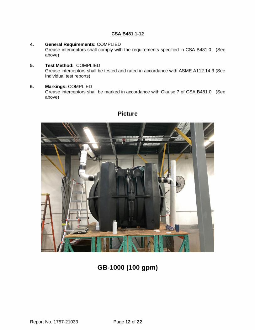
4. General Requirements: COMPLIED Grease interceptors shall comply with the requirements specified in CSA B481.0. (See above)
5. Test Method: COMPLIED
Grease interceptors shall be tested and rated in accordance with ASME A112.14.3 (See Individual test reports)
6. Markings: COMPLIED Grease interceptors shall be marked in accordance with Clause 7 of CSA B481.0. (See above)
Picture
GB-1000 (100 gpm)

Report No. 1757-21033 Page 13 of 22
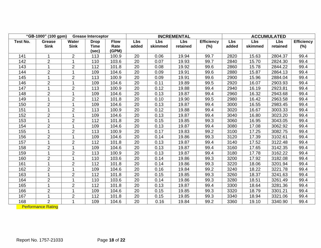
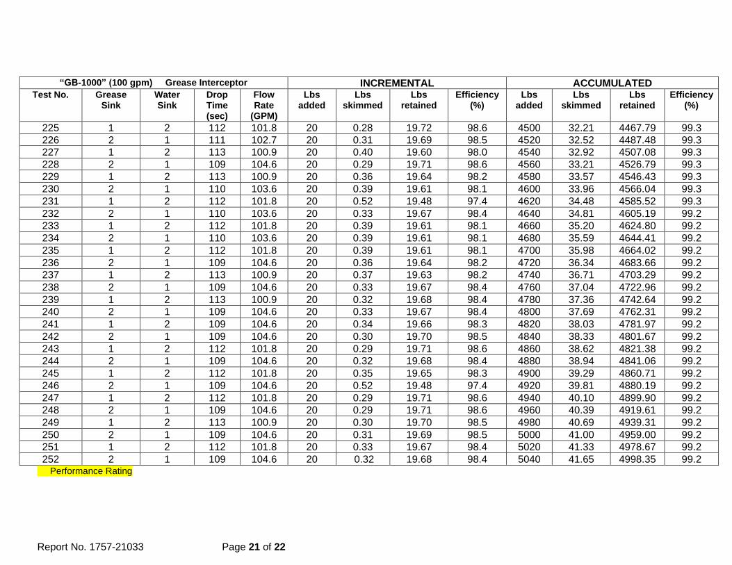
TABLE 1 – Test Results per ASME A112.14.3-2018
“GB-1000” (100 gpm) Grease Interceptor INCREMENTAL ACCUMULATED Test No. Grease
Sink Water Sink
Drop Time (sec)
Flow Rate
(GPM)
Lbs added
Lbs skimmed
Lbs retained
Efficiency (%)
Lbs added
Lbs skimmed
Lbs retained
Efficiency (%)
1 1 2 113 100.9 20 0.00 20.00 100 20 0.00 20.00 100
2 2 1 109 104.6 20 0.01 19.99 100 40 0.01 39.99 100
3 1 2 112 101.8 20 0.02 19.98 99.9 60 0.03 59.97 100
4 2 1 110 103.6 20 0.04 19.96 99.8 80 0.07 79.93 99.9
5 1 2 110 103.6 20 0.08 19.92 99.6 100 0.15 99.85 99.9
6 2 1 109 104.6 20 0.08 19.92 99.6 120 0.23 119.77 99.8
7 1 2 112 101.8 20 0.08 19.92 99.6 140 0.31 139.69 99.8
8 2 1 109 104.6 20 0.08 19.92 99.6 160 0.39 159.61 99.8
9 1 2 112 101.8 20 0.09 19.91 99.6 180 0.48 179.52 99.7
10 2 1 109 104.6 20 0.08 19.92 99.6 200 0.56 199.44 99.7
11 1 2 112 101.8 20 0.11 19.89 99.5 220 0.67 219.33 99.7
12 2 1 109 104.6 20 0.10 19.90 99.5 240 0.77 239.23 99.7
13 1 2 111 102.7 20 0.08 19.92 99.6 260 0.85 259.15 99.7
14 2 1 109 104.6 20 0.09 19.91 99.6 280 0.94 279.06 99.7
15 1 2 111 102.7 20 0.10 19.90 99.5 300 1.04 298.96 99.7
16 2 1 109 104.6 20 0.12 19.88 99.4 320 1.16 318.84 99.6
17 1 2 113 100.9 20 0.12 19.88 99.4 340 1.28 338.72 99.6
18 2 1 109 104.6 20 0.12 19.88 99.4 360 1.40 358.60 99.6
19 1 2 112 101.8 20 0.12 19.88 99.4 380 1.52 378.48 99.6
20 2 1 110 103.6 20 0.11 19.89 99.5 400 1.63 398.37 99.6
21 1 2 112 101.8 20 0.12 19.88 99.4 420 1.75 418.25 99.6
22 2 1 109 104.6 20 0.10 19.90 99.5 440 1.85 438.15 99.6
23 1 2 113 100.9 20 0.13 19.87 99.4 460 1.98 458.02 99.6
24 2 1 109 104.6 20 0.12 19.88 99.4 480 2.10 477.90 99.6
25 1 2 111 102.7 20 0.12 19.88 99.4 500 2.22 497.78 99.6
26 2 1 109 104.6 20 0.13 19.87 99.4 520 2.35 517.65 99.5
27 1 2 111 102.7 20 0.14 19.86 99.3 540 2.49 537.51 99.5
28 2 1 110 103.6 20 0.09 19.91 99.6 560 2.58 557.42 99.5 Performance Rating
Report No. 1757-21033 Page 14 of 22
“GB-1000” (100 gpm) Grease Interceptor INCREMENTAL ACCUMULATED Test No. Grease
Sink Water Sink
Drop Time (sec)
Flow Rate
(GPM)
Lbs added
Lbs skimmed
Lbs retained
Efficiency (%)
Lbs added
Lbs skimmed
Lbs retained
Efficiency (%)
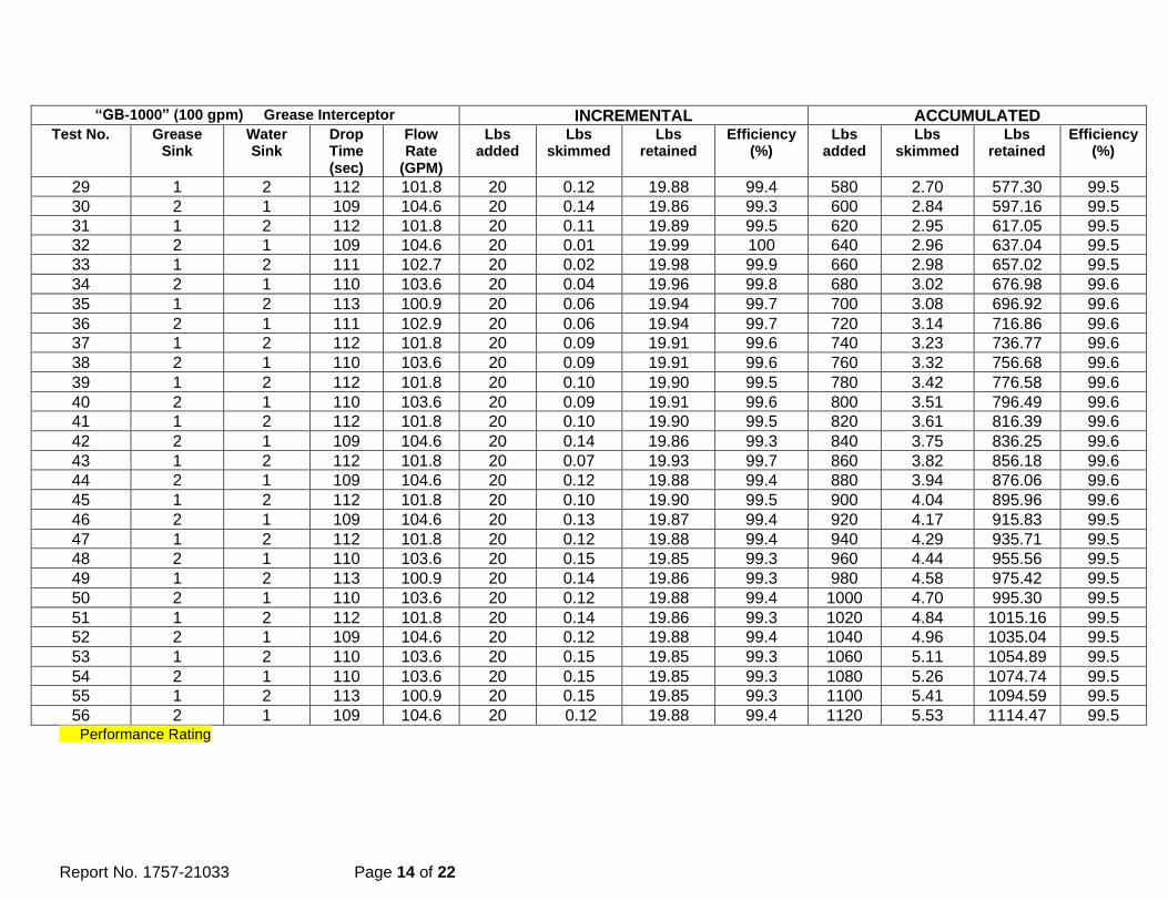
29 1 2 112 101.8 20 0.12 19.88 99.4 580 2.70 577.30 99.5
30 2 1 109 104.6 20 0.14 19.86 99.3 600 2.84 597.16 99.5
31 1 2 112 101.8 20 0.11 19.89 99.5 620 2.95 617.05 99.5
32 2 1 109 104.6 20 0.01 19.99 100 640 2.96 637.04 99.5
33 1 2 111 102.7 20 0.02 19.98 99.9 660 2.98 657.02 99.5
34 2 1 110 103.6 20 0.04 19.96 99.8 680 3.02 676.98 99.6
35 1 2 113 100.9 20 0.06 19.94 99.7 700 3.08 696.92 99.6
36 2 1 111 102.9 20 0.06 19.94 99.7 720 3.14 716.86 99.6
37 1 2 112 101.8 20 0.09 19.91 99.6 740 3.23 736.77 99.6
38 2 1 110 103.6 20 0.09 19.91 99.6 760 3.32 756.68 99.6
39 1 2 112 101.8 20 0.10 19.90 99.5 780 3.42 776.58 99.6
40 2 1 110 103.6 20 0.09 19.91 99.6 800 3.51 796.49 99.6
41 1 2 112 101.8 20 0.10 19.90 99.5 820 3.61 816.39 99.6
42 2 1 109 104.6 20 0.14 19.86 99.3 840 3.75 836.25 99.6
43 1 2 112 101.8 20 0.07 19.93 99.7 860 3.82 856.18 99.6
44 2 1 109 104.6 20 0.12 19.88 99.4 880 3.94 876.06 99.6
45 1 2 112 101.8 20 0.10 19.90 99.5 900 4.04 895.96 99.6
46 2 1 109 104.6 20 0.13 19.87 99.4 920 4.17 915.83 99.5
47 1 2 112 101.8 20 0.12 19.88 99.4 940 4.29 935.71 99.5
48 2 1 110 103.6 20 0.15 19.85 99.3 960 4.44 955.56 99.5
49 1 2 113 100.9 20 0.14 19.86 99.3 980 4.58 975.42 99.5
50 2 1 110 103.6 20 0.12 19.88 99.4 1000 4.70 995.30 99.5
51 1 2 112 101.8 20 0.14 19.86 99.3 1020 4.84 1015.16 99.5
52 2 1 109 104.6 20 0.12 19.88 99.4 1040 4.96 1035.04 99.5
53 1 2 110 103.6 20 0.15 19.85 99.3 1060 5.11 1054.89 99.5
54 2 1 110 103.6 20 0.15 19.85 99.3 1080 5.26 1074.74 99.5
55 1 2 113 100.9 20 0.15 19.85 99.3 1100 5.41 1094.59 99.5
56 2 1 109 104.6 20 0.12 19.88 99.4 1120 5.53 1114.47 99.5 Performance Rating
Report No. 1757-21033 Page 15 of 22
“GB-1000” (100 gpm) Grease Interceptor INCREMENTAL ACCUMULATED Test No. Grease
Sink Water Sink
Drop Time (sec)
Flow Rate
(GPM)
Lbs added
Lbs skimmed
Lbs retained
Efficiency (%)
Lbs added
Lbs skimmed
Lbs retained
Efficiency (%)
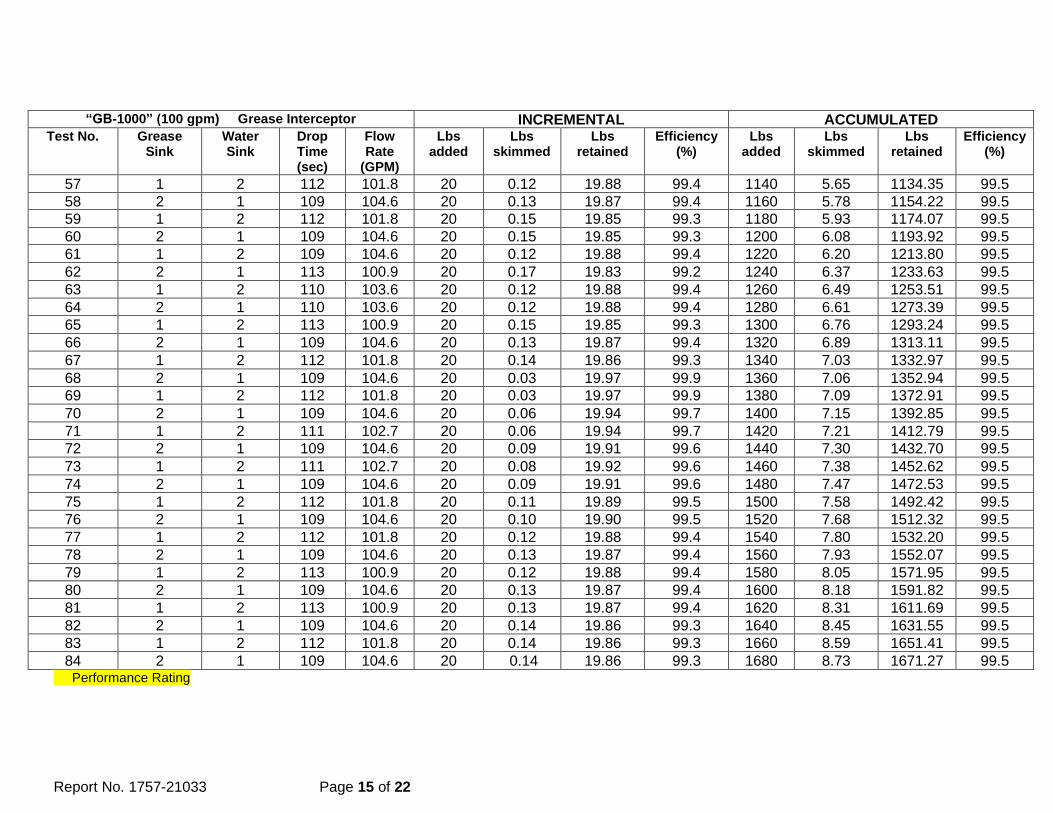
57 1 2 112 101.8 20 0.12 19.88 99.4 1140 5.65 1134.35 99.5
58 2 1 109 104.6 20 0.13 19.87 99.4 1160 5.78 1154.22 99.5
59 1 2 112 101.8 20 0.15 19.85 99.3 1180 5.93 1174.07 99.5
60 2 1 109 104.6 20 0.15 19.85 99.3 1200 6.08 1193.92 99.5
61 1 2 109 104.6 20 0.12 19.88 99.4 1220 6.20 1213.80 99.5
62 2 1 113 100.9 20 0.17 19.83 99.2 1240 6.37 1233.63 99.5
63 1 2 110 103.6 20 0.12 19.88 99.4 1260 6.49 1253.51 99.5
64 2 1 110 103.6 20 0.12 19.88 99.4 1280 6.61 1273.39 99.5
65 1 2 113 100.9 20 0.15 19.85 99.3 1300 6.76 1293.24 99.5
66 2 1 109 104.6 20 0.13 19.87 99.4 1320 6.89 1313.11 99.5
67 1 2 112 101.8 20 0.14 19.86 99.3 1340 7.03 1332.97 99.5
68 2 1 109 104.6 20 0.03 19.97 99.9 1360 7.06 1352.94 99.5
69 1 2 112 101.8 20 0.03 19.97 99.9 1380 7.09 1372.91 99.5
70 2 1 109 104.6 20 0.06 19.94 99.7 1400 7.15 1392.85 99.5
71 1 2 111 102.7 20 0.06 19.94 99.7 1420 7.21 1412.79 99.5
72 2 1 109 104.6 20 0.09 19.91 99.6 1440 7.30 1432.70 99.5
73 1 2 111 102.7 20 0.08 19.92 99.6 1460 7.38 1452.62 99.5
74 2 1 109 104.6 20 0.09 19.91 99.6 1480 7.47 1472.53 99.5
75 1 2 112 101.8 20 0.11 19.89 99.5 1500 7.58 1492.42 99.5
76 2 1 109 104.6 20 0.10 19.90 99.5 1520 7.68 1512.32 99.5
77 1 2 112 101.8 20 0.12 19.88 99.4 1540 7.80 1532.20 99.5
78 2 1 109 104.6 20 0.13 19.87 99.4 1560 7.93 1552.07 99.5
79 1 2 113 100.9 20 0.12 19.88 99.4 1580 8.05 1571.95 99.5
80 2 1 109 104.6 20 0.13 19.87 99.4 1600 8.18 1591.82 99.5
81 1 2 113 100.9 20 0.13 19.87 99.4 1620 8.31 1611.69 99.5
82 2 1 109 104.6 20 0.14 19.86 99.3 1640 8.45 1631.55 99.5
83 1 2 112 101.8 20 0.14 19.86 99.3 1660 8.59 1651.41 99.5
84 2 1 109 104.6 20 0.14 19.86 99.3 1680 8.73 1671.27 99.5 Performance Rating

Report No. 1757-21033 Page 16 of 22
“GB-1000” (100 gpm) Grease Interceptor INCREMENTAL ACCUMULATED Test No. Grease
Sink Water Sink
Drop Time (sec)
Flow Rate
(GPM)
Lbs added
Lbs skimmed
Lbs retained
Efficiency (%)
Lbs added
Lbs skimmed
Lbs retained
Efficiency (%)
85 1 2 112 101.8 20 0.12 19.88 99.4 1700 8.85 1691.15 99.5
86 2 1 109 104.6 20 0.14 19.86 99.3 1720 8.99 1711.01 99.5
87 1 2 113 100.9 20 0.12 19.88 99.4 1740 9.11 1730.89 99.5
88 2 1 109 104.6 20 0.12 19.88 99.4 1760 9.23 1750.77 99.5
89 1 2 112 101.8 20 0.16 19.84 99.2 1780 9.39 1770.61 99.5
90 2 1 109 104.6 20 0.13 19.87 99.4 1800 9.52 1790.48 99.5
91 1 2 113 100.9 20 0.15 19.85 99.3 1820 9.67 1810.33 99.5
92 2 1 109 104.6 20 0.12 19.88 99.4 1840 9.79 1830.21 99.5
93 1 2 111 102.7 20 0.13 19.87 99.4 1860 9.92 1850.08 99.5
94 2 1 110 103.6 20 0.13 19.87 99.4 1880 10.05 1869.95 99.5
95 1 2 112 101.8 20 0.12 19.88 99.4 1900 10.17 1889.83 99.5
96 2 1 109 104.6 20 0.12 19.88 99.4 1920 10.29 1909.77 99.5
97 1 2 112 101.8 20 0.15 19.85 99.3 1940 10.44 1929.56 99.5
98 2 1 110 103.6 20 0.15 19.85 99.3 1960 10.59 1949.41 99.5
99 1 2 112 101.8 20 0.13 19.87 99.4 1980 10.72 1969.28 99.5
100 2 1 109 104.6 20 0.14 19.86 99.3 2000 10.86 1989.14 99.5
101 1 2 113 100.9 20 0.14 19.86 99.3 2020 11.00 2009.00 99.5
102 2 1 109 104.6 20 0.13 19.87 99.4 2040 11.13 2028.87 99.5
103 1 2 112 101.8 20 0.11 19.89 99.5 2060 11.24 2048.76 99.5
104 2 1 109 104.6 20 0.03 19.97 99.9 2080 11.27 2068.73 99.5
105 1 2 113 100.9 20 0.04 19.96 99.8 2100 11.31 2088.69 99.5
106 2 1 109 104.6 20 0.06 19.94 99.7 2120 11.37 2108.63 99.5
107 1 2 112 101.8 20 0.07 19.93 99.7 2140 11.44 2128.56 99.5
108 2 1 109 104.6 20 0.07 19.93 99.7 2160 11.51 2148.49 99.5
109 1 2 112 101.8 20 0.12 19.88 99.4 2180 11.63 2168.37 99.5
110 2 1 109 104.6 20 0.08 19.92 99.6 2200 11.71 2188.29 99.5
111 1 2 112 101.8 20 0.10 19.90 99.5 2220 11.81 2208.19 99.5
112 2 1 109 104.6 20 0.10 19.90 99.5 2240 11.91 2228.09 99.5 Performance Rating

Report No. 1757-21033 Page 17 of 22
“GB-1000” (100 gpm) Grease Interceptor INCREMENTAL ACCUMULATED Test No. Grease
Sink Water Sink
Drop Time (sec)
Flow Rate
(GPM)
Lbs added
Lbs skimmed
Lbs retained
Efficiency (%)
Lbs added
Lbs skimmed
Lbs retained
Efficiency (%)
113 1 2 113 100.9 20 0.14 19.81 99.3 2260 12.05 2247.95 99.5
114 2 1 109 104.6 20 0.12 19.88 99.4 2280 12.17 2267.83 99.5
115 1 2 112 101.8 20 0.13 19.87 99.4 2300 12.30 2287.70 99.5
116 2 1 110 103.6 20 0.12 19.88 99.4 2320 12.42 2307.58 99.5
117 1 2 113 100.9 20 0.14 19.86 99.3 2340 12.56 2327.44 99.5
118 2 1 109 104.6 20 0.12 19.88 99.4 2360 12.68 2347.32 99.5
119 1 2 112 101.8 20 0.14 19.86 99.3 2380 12.82 2367.18 99.5
120 2 1 109 104.6 20 0.13 19.87 99.4 2400 12.95 2387.05 99.5
121 1 2 112 101.8 20 0.13 19.87 99.4 2420 13.08 2406.92 99.5
122 2 1 109 104.6 20 0.13 19.87 99.4 2440 13.21 2426.79 99.5
123 1 2 111 102.9 20 0.14 19.86 99.3 2460 13.35 2446.65 99.5
124 2 1 109 104.6 20 0.14 19.86 99.3 2480 13.49 2466.51 99.5
125 1 2 112 101.8 20 0.15 19.85 99.3 2500 13.64 2486.36 99.5
126 2 1 110 103.6 20 0.16 19.84 99.2 2520 13.80 2506.20 99.5
127 1 2 113 100.9 20 0.11 19.89 99.5 2540 13.91 2526.09 99.5
128 2 1 110 103.6 20 0.14 19.86 99.3 2560 14.05 2545.95 99.5
129 1 2 112 101.8 20 0.12 19.88 99.4 2580 14.17 2565.83 99.5
130 2 1 109 104.6 20 0.14 19.86 99.3 2600 14.31 2585.69 99.4
131 1 2 111 102.7 20 0.12 19.88 99.4 2620 14.43 2605.57 99.4
132 2 1 109 104.6 20 0.13 19.87 99.4 2640 14.56 2625.44 99.4
133 1 2 111 102.7 20 0.14 19.86 99.3 2660 14.70 2645.30 99.4
134 2 1 109 104.6 20 0.13 19.87 99.4 2680 14.83 2665.17 99.4
135 1 2 113 100.9 20 0.13 19.87 99.4 2700 14.96 2685.04 99.4
136 2 1 109 104.6 20 0.13 19.87 99.4 2720 15.09 2704.91 99.4
137 1 2 112 101.8 20 0.14 19.86 99.3 2740 15.23 2724.77 99.4
138 2 1 109 104.6 20 0.13 19.87 99.4 2760 15.36 2744.64 99.4
139 1 2 112 101.8 20 0.14 19.86 99.3 2780 15.50 2764.50 99.4
140 2 1 110 103.6 20 0.07 19.93 99.7 2800 15.57 2784.43 99.4 Performance Rating
Report No. 1757-21033 Page 18 of 22
“GB-1000” (100 gpm) Grease Interceptor INCREMENTAL ACCUMULATED Test No. Grease
Sink Water Sink
Drop Time (sec)
Flow Rate
(GPM)
Lbs added
Lbs skimmed
Lbs retained
Efficiency (%)
Lbs added
Lbs skimmed
Lbs retained
Efficiency (%)
141 1 2 113 100.9 20 0.06 19.94 99.7 2820 15.63 2804.37 99.4
142 2 1 110 103.6 20 0.07 19.93 99.7 2840 15.70 2824.30 99.4
143 1 2 112 101.8 20 0.08 19.92 99.6 2860 15.78 2844.22 99.4
144 2 1 109 104.6 20 0.09 19.91 99.6 2880 15.87 2864.13 99.4
145 1 2 113 100.9 20 0.09 19.91 99.6 2900 15.96 2884.04 99.4
146 2 1 109 104.6 20 0.11 19.89 99.5 2920 16.07 2903.93 99.4
147 1 2 113 100.9 20 0.12 19.88 99.4 2940 16.19 2923.81 99.4
148 2 1 109 104.6 20 0.13 19.87 99.4 2960 16.32 2943.68 99.4
149 1 2 112 101.8 20 0.10 19.90 99.5 2980 16.42 2963.58 99.4
150 2 1 109 104.6 20 0.13 19.87 99.4 3000 16.55 2983.45 99.4
151 1 2 113 100.9 20 0.12 19.88 99.4 3020 16.67 3003.33 99.4
152 2 1 109 104.6 20 0.13 19.87 99.4 3040 16.80 3023.20 99.4
153 1 2 112 101.8 20 0.15 19.85 99.3 3060 16.95 3043.05 99.4
154 2 1 109 104.6 20 0.13 19.87 99.4 3080 17.08 3062.92 99.4
155 1 2 113 100.9 20 0.17 19.83 99.2 3100 17.25 3082.75 99.4
156 2 1 109 104.6 20 0.14 19.86 99.3 3120 17.39 3102.61 99.4
157 1 2 112 101.8 20 0.13 19.87 99.4 3140 17.52 3122.48 99.4
158 2 1 109 104.6 20 0.13 19.87 99.4 3160 17.65 3142.35 99.4
159 1 2 113 100.9 20 0.13 19.87 99.4 3180 17.78 3162.22 99.4
160 2 1 110 103.6 20 0.14 19.86 99.3 3200 17.92 3182.08 99.4
161 1 2 112 101.8 20 0.14 19.86 99.3 3220 18.06 3201.94 99.4
162 2 1 109 104.6 20 0.16 19.84 99.2 3240 18.22 3221.78 99.4
163 1 2 112 101.8 20 0.15 19.85 99.3 3260 18.37 3241.63 99.4
164 2 1 110 103.6 20 0.14 19.86 99.3 3280 18.51 3261.49 99.4
165 1 2 112 101.8 20 0.13 19.87 99.4 3300 18.64 3281.36 99.4
166 2 1 109 104.6 20 0.15 19.85 99.3 3320 18.79 3301.21 99.4
167 1 2 112 101.8 20 0.15 19.85 99.3 3340 18.94 3321.06 99.4
168 2 1 109 104.6 20 0.16 19.84 99.2 3360 19.10 3340.90 99.4 Performance Rating

Report No. 1757-21033 Page 19 of 22
“GB-1000” (100 gpm) Grease Interceptor INCREMENTAL ACCUMULATED Test No. Grease
Sink Water Sink
Drop Time (sec)
Flow Rate
(GPM)
Lbs added
Lbs skimmed
Lbs retained
Efficiency (%)
Lbs added
Lbs skimmed
Lbs retained
Efficiency (%)
169 1 2 111 102.7 20 0.15 19.85 99.3 3380 19.25 3360.75 99.4
170 2 1 110 103.6 20 0.15 19.85 99.3 3400 19.40 3380.60 99.4
171 1 2 112 101.8 20 0.16 19.84 99.2 3420 19.56 3400.44 99.4
172 2 1 109 104.6 20 0.18 19.82 99.1 3440 19.74 3420.26 99.4
173 1 2 112 101.8 20 0.15 19.85 99.3 3460 19.89 3440.11 99.4
174 2 1 109 104.6 20 0.17 19.83 99.2 3480 20.06 3459.94 99.4
175 1 2 111 102.7 20 0.17 19.83 99.2 3500 20.23 3479.77 99.4
176 2 1 109 104.6 20 0.27 19.73 98.7 3520 20.50 3499.50 99.4
177 1 2 113 100.9 20 0.12 19.88 99.4 3540 20.62 3519.38 99.4
178 2 1 110 103.6 20 0.11 19.89 99.5 3560 20.73 3539.27 99.4
179 1 2 113 100.9 20 0.13 19.87 99.4 3580 20.86 3559.14 99.4
180 2 1 109 104.6 20 0.12 19.88 99.4 3600 20.98 3579.02 99.4
181 1 2 113 100.9 20 0.14 19.86 99.3 3620 21.12 3598.88 99.4
182 2 1 109 104.6 20 0.18 19.82 99.1 3640 21.30 3618.70 99.4
183 1 2 113 100.9 20 0.20 19.80 99.0 3660 21.50 3638.50 99.4
184 2 1 109 104.6 20 0.20 19.80 99.0 3680 21.70 3658.30 99.4
185 1 2 112 101.8 20 0.24 19.76 98.8 3700 21.94 3678.06 99.4
186 2 1 109 104.6 20 0.21 19.79 99.0 3720 22.15 3697.85 99.4
187 1 2 112 101.8 20 0.22 19.78 98.9 3740 22.37 3717.63 99.4
188 2 1 109 104.6 20 0.22 19.78 98.9 3760 22.59 3737.41 99.4
189 1 2 113 100.9 20 0.28 19.72 98.6 3780 22.87 3757.13 99.4
190 2 1 109 104.6 20 0.22 19.78 98.9 3800 23.09 3776.91 99.4
191 1 2 112 101.8 20 0.26 19.74 98.7 3820 23.35 3796.65 99.4
192 2 1 109 104.6 20 0.25 19.75 98.8 3840 23.60 3816.40 99.4
193 1 2 113 100.9 20 0.28 19.72 98.6 3860 23.88 3836.12 99.4
194 2 1 110 103.6 20 0.23 19.77 98.9 3880 24.11 3855.89 99.4
195 1 2 113 100.9 20 0.27 19.73 98.7 3900 24.38 3875.62 99.4
196 2 1 109 104.6 20 0.26 19.74 98.7 3920 24.64 3895.36 99.4 Performance Rating

Report No. 1757-21033 Page 20 of 22
“GB-1000” (100 gpm) Grease Interceptor INCREMENTAL ACCUMULATED Test No. Grease
Sink Water Sink
Drop Time (sec)
Flow Rate
(GPM)
Lbs added
Lbs skimmed
Lbs retained
Efficiency (%)
Lbs added
Lbs skimmed
Lbs retained
Efficiency (%)
197 1 2 113 100.9 20 0.36 19.64 98.2 3940 25.00 3915.00 99.4
198 2 1 109 104.6 20 0.31 19.69 98.5 3960 25.31 3934.69 99.4
199 1 2 112 101.8 20 0.29 19.71 98.6 3980 25.60 3954.40 99.4
200 2 1 109 104.6 20 0.23 19.77 98.9 4000 25.83 3974.17 99.4
201 1 2 113 100.9 20 0.28 19.72 98.6 4020 26.11 3993.89 99.4
202 2 1 110 103.6 20 0.27 19.73 98.7 4040 26.38 4013.62 99.3
203 1 2 112 101.8 20 0.32 19.68 98.4 4060 26.70 4033.30 99.3
204 2 1 109 104.6 20 0.28 19.72 98.6 4080 26.98 4053.02 99.3
205 1 2 112 101.8 20 0.30 19.70 98.5 4100 27.28 4072.72 99.3
206 2 1 109 104.6 20 0.27 19.73 98.7 4120 27.55 4092.45 99.3
207 1 2 112 101.8 20 0.30 19.70 98.5 4140 27.85 4112.15 99.3
208 2 1 109 104.6 20 0.27 19.73 98.7 4160 28.12 4131.88 99.3
209 1 2 112 101.8 20 0.33 19.67 98.4 4180 28.45 4151.55 99.3
210 2 1 109 104.6 20 0.23 19.77 98.9 4200 28.68 4171.32 99.3
211 1 2 113 100.9 20 0.16 19.84 99.2 4220 28.84 4191.16 99.3
212 2 1 111 102.7 20 0.11 19.89 99.5 4240 28.95 4211.05 99.3
213 1 2 113 100.9 20 0.16 19.84 99.2 4260 29.11 4230.89 99.3
214 2 1 111 102.7 20 0.20 19.80 99.0 4280 29.31 4250.69 99.3
215 1 2 113 100.9 20 0.20 19.80 99.0 4300 29.51 4270.49 99.3
216 2 1 111 102.7 20 0.24 19.76 98.8 4320 29.75 4290.25 99.3
217 1 2 113 100.9 20 0.24 19.76 98.8 4340 29.99 4310.01 99.3
218 2 1 110 103.6 20 0.26 19.74 98.7 4360 30.25 4329.75 99.3
219 1 2 111 102.7 20 0.27 19.73 98.7 4380 30.52 4349.48 99.3
220 2 1 110 103.6 20 0.24 19.76 98.8 4400 30.76 4369.24 99.3
221 1 2 112 101.8 20 0.30 19.70 98.5 4420 31.06 4388.94 99.3
222 2 1 110 103.6 20 0.30 19.70 98.5 4440 31.36 4408.64 99.3
223 1 2 113 100.9 20 0.30 19.70 98.5 4460 31.66 4428.34 99.3
224 2 1 109 104.6 20 0.27 19.73 98.7 4480 31.93 4448.07 99.3 Performance Rating
Report No. 1757-21033 Page 21 of 22
“GB-1000” (100 gpm) Grease Interceptor INCREMENTAL ACCUMULATED Test No. Grease
Sink Water Sink
Drop Time (sec)
Flow Rate
(GPM)
Lbs added
Lbs skimmed
Lbs retained
Efficiency (%)
Lbs added
Lbs skimmed
Lbs retained
Efficiency (%)
225 1 2 112 101.8 20 0.28 19.72 98.6 4500 32.21 4467.79 99.3
226 2 1 111 102.7 20 0.31 19.69 98.5 4520 32.52 4487.48 99.3
227 1 2 113 100.9 20 0.40 19.60 98.0 4540 32.92 4507.08 99.3
228 2 1 109 104.6 20 0.29 19.71 98.6 4560 33.21 4526.79 99.3
229 1 2 113 100.9 20 0.36 19.64 98.2 4580 33.57 4546.43 99.3
230 2 1 110 103.6 20 0.39 19.61 98.1 4600 33.96 4566.04 99.3
231 1 2 112 101.8 20 0.52 19.48 97.4 4620 34.48 4585.52 99.3
232 2 1 110 103.6 20 0.33 19.67 98.4 4640 34.81 4605.19 99.2
233 1 2 112 101.8 20 0.39 19.61 98.1 4660 35.20 4624.80 99.2
234 2 1 110 103.6 20 0.39 19.61 98.1 4680 35.59 4644.41 99.2
235 1 2 112 101.8 20 0.39 19.61 98.1 4700 35.98 4664.02 99.2
236 2 1 109 104.6 20 0.36 19.64 98.2 4720 36.34 4683.66 99.2
237 1 2 113 100.9 20 0.37 19.63 98.2 4740 36.71 4703.29 99.2
238 2 1 109 104.6 20 0.33 19.67 98.4 4760 37.04 4722.96 99.2
239 1 2 113 100.9 20 0.32 19.68 98.4 4780 37.36 4742.64 99.2
240 2 1 109 104.6 20 0.33 19.67 98.4 4800 37.69 4762.31 99.2
241 1 2 109 104.6 20 0.34 19.66 98.3 4820 38.03 4781.97 99.2
242 2 1 109 104.6 20 0.30 19.70 98.5 4840 38.33 4801.67 99.2
243 1 2 112 101.8 20 0.29 19.71 98.6 4860 38.62 4821.38 99.2
244 2 1 109 104.6 20 0.32 19.68 98.4 4880 38.94 4841.06 99.2
245 1 2 112 101.8 20 0.35 19.65 98.3 4900 39.29 4860.71 99.2
246 2 1 109 104.6 20 0.52 19.48 97.4 4920 39.81 4880.19 99.2
247 1 2 112 101.8 20 0.29 19.71 98.6 4940 40.10 4899.90 99.2
248 2 1 109 104.6 20 0.29 19.71 98.6 4960 40.39 4919.61 99.2
249 1 2 113 100.9 20 0.30 19.70 98.5 4980 40.69 4939.31 99.2
250 2 1 109 104.6 20 0.31 19.69 98.5 5000 41.00 4959.00 99.2
251 1 2 112 101.8 20 0.33 19.67 98.4 5020 41.33 4978.67 99.2
252 2 1 109 104.6 20 0.32 19.68 98.4 5040 41.65 4998.35 99.2 Performance Rating
Report No. 1757-21033 Page 22 of 22
“GB-1000” (100 gpm) Grease Interceptor INCREMENTAL ACCUMULATED Test No. Grease
Sink Water Sink
Drop Time (sec)
Flow Rate
(GPM)
Lbs added
Lbs skimmed
Lbs retained
Efficiency (%)
Lbs added
Lbs skimmed
Lbs retained
Efficiency (%)
253 1 2 112 101.8 20 0.37 19.63 98.2 5060 42.02 5017.98 99.2
254 2 1 109 104.6 20 0.36 19.64 98.2 5080 42.38 5037.62 99.2
255 1 2 112 101.8 20 0.36 19.64 98.2 5100 42.74 5057.26 99.2
256 2 1 109 104.6 20 0.39 19.61 98.1 5120 43.13 5076.87 99.2
257 1 2 111 102.7 20 0.41 19.59 98.0 5140 43.54 5096.46 99.2
258 2 1 109 104.6 20 0.43 19.57 97.9 5160 43.97 5116.03 99.1
259 1 2 112 101.8 20 0.41 19.59 98.0 5180 44.38 5135.62 99.1
260 2 1 109 104.6 20 0.41 19.59 98.0 5200 44.79 5155.21 99.1
261 1 2 112 101.8 20 0.46 19.54 97.7 5220 45.25 5174.75 99.1
262 2 1 109 104.6 20 0.43 19.57 97.9 5240 45.68 5194.32 99.1
263 1 2 110 103.6 20 0.50 19.50 97.5 5260 46.18 5213.82 99.1
264 2 1 109 104.6 20 0.47 19.53 97.7 5280 46.65 5233.35 99.1
265 1 2 111 102.7 20 0.59 19.41 97.1 5300 47.24 5252.76 99.1
266 2 1 109 104.6 20 0.61 19.39 97.0 5320 47.85 5272.15 99.1
267 1 2 112 101.8 20 0.62 19.38 96.9 5340 48.47 5291.53 99.1
268 2 1 110 103.6 20 0.86 19.14 95.7 5360 49.33 5310.67 99.1
269 1 2 111 102.7 20 0.79 19.21 96.1 5380 50.12 5329.88 99.1
270 2 1 109 104.6 20 0.80 19.20 96.0 5400 50.92 5349.08 99.1
271 1 2 111 102.7 20 0.88 19.12 95.6 5420 51.80 5368.20 99.0
272 2 1 109 104.6 20 1.17 18.83 94.2 5440 52.97 5387.03 99.0
273 1 2 112 101.8 20 1.16 18.84 94.2 5460 54.13 5405.87 99.0
274 2 1 109 104.6 20 1.34 18.66 93.3 5480 55.47 5424.53 99.0
275 1 2 111 102.7 20 1.52 18.48 92.4 5500 56.99 5443.01 99.0
276 2 1 109 104.6 20 1.81 18.19 91.0 5520 58.80 5461.20 98.9
277 1 2 111 102.7 20 2.41 17.59 88.0 5540 61.21 5478.79 98.9
278 2 1 109 104.6 20 3.44 16.56 82.8 5560 64.65 5495.35 98.8
279 1 2 112 101.8 20 5.24 14.76 73.8 5580 69.89 5510.11 98.7
280 2 1 109 104.6 20 8.35 11.65 58.3 5600 78.24 5521.76 98.6 Performance Rating
Related Documents