® The contents of this report reflect the views of the authors, who are responsible for the facts and the accuracy of the information presented herein. This document is disseminated under the sponsorship of the Department of Transportation University Transportation Centers Program, in the interest of information exchange. The U.S. Government assumes no liability for the contents or use thereof. Splice Performance Evaluation of Enamel- Coated Rebar for Structural Safety Report # MATC-MS&T: 194 Final Report G.D. Chen, Ph.D., P.E., F .ASCE, F .Sei Professor and Robert W. Abbett Distinguished Chair in Engineering Department of Civil, Architectural, and Environmental Engineering Missouri University of Science and Technology 2014 A Coopertative Research Project sponsored by U.S. Department of Tranportation-Research, Innovation and Technology Innovation Administration WBS:25-1121-0003-194 C.L. Wu, Ph.D. candidate Graduate Research Assisstant Department of Civil, Architectural, and Environmental Engineering MIssouri University of Science and Technology

Welcome message from author
This document is posted to help you gain knowledge. Please leave a comment to let me know what you think about it! Share it to your friends and learn new things together.
Transcript

®
The contents of this report reflect the views of the authors, who are responsible for the facts and the accuracy of the information presented herein. This document is disseminated under the sponsorship of the Department of Transportation
University Transportation Centers Program, in the interest of information exchange. The U.S. Government assumes no liability for the contents or use thereof.
Splice Performance Evaluation of Enamel-Coated Rebar for Structural Safety
Report # MATC-MS&T: 194 Final Report
G.D. Chen, Ph.D., P.E., F .ASCE, F .SeiProfessor and Robert W. Abbett Distinguished Chair in EngineeringDepartment of Civil, Architectural, and Environmental EngineeringMissouri University of Science and Technology
2014
A Coopertative Research Project sponsored by U.S. Department of Tranportation-Research, Innovation and Technology Innovation Administration
WBS:25-1121-0003-194
C.L. Wu, Ph.D. candidateGraduate Research Assisstant
Department of Civil, Architectural, and Environmental Engineering
MIssouri University of Science and Technology

Splice Performance Evaluation of Enamel-Coated Rebar for Structural Safety
G.D. Chen, Ph.D., P.E., F.ASCE, F.SEI
Professor and Robert W. Abbett Distinguished Chair in Civil Engineering
Department of Civil, Architectural, and Environmental Engineering
Missouri University of Science and Technology
C.L. Wu, Ph.D. Candidate
Graduate Research Assistant
Department of Civil, Architectural, and Environmental Engineering
Missouri University of Science and Technology
A Report on Research Sponsored By
Mid-America Transportation Center
University of Nebraska–Lincoln
US DOT Research and Innovative Technology Administration
Center for Infrastructure Engineering Studies
Missouri University of Science and Technology
July 2014

ii
Technical Report Documentation Page 1. Report No.
25-1121-0003-194
2. Government Accession No.
3. Recipient's Catalog No.
4. Title and Subtitle
Splice Performance Evaluation of Enamel-coated Rebar for Structural Safety
5. Report Date
July 2014
6. Performing Organization Code
7. Author(s)
G.D. Chen and C.L. Wu
8. Performing Organization Report No.
25-1121-0003-194
9. Performing Organization Name and Address
Mid-America Transportation Center
2200 Vine St.
PO Box 830851
Lincoln, NE 68583-0851
10. Work Unit No. (TRAIS)
11. Contract or Grant No.
12. Sponsoring Agency Name and Address
Research and Innovative Technology Administration
1200 New Jersey Ave., SE
Washington, D.C. 20590
13. Type of Report and Period Covered
Final Report,
July 2012 - June 2014
14. Sponsoring Agency Code
MATC TRB RiP No. 17139
(this listing includes the scope of both
MATC project numbers associated with
this project)
15. Supplementary Notes
16. Abstract
This report summarizes the findings and results from an experimental study of vitreous enamel coating effects on the bond
strength between deformed rebar and normal strength concrete. A total of 24 beam splice specimens were tested under four-
point loading with four parameters investigated: bar size, lap splice length, coating, and confinement conditions. As the splice
length increases, the ratio of bond strength between coated rebar and black rebar first increases from 1.0 to a maximum value
of 1.44, and then decreases to 1.0. The maximum bond strength ratio corresponds to the near initial yielding of coated rebar.
On the average, enamel coating can increase the bond strength of steel rebar in concrete by approximately 15%. A coating
factor of 0.85 is thus recommended to take into account the enamel coating effect in lap splice designs, according to ACI
and AASHTO bond strength equations.
17. Key Words
Enamel coating, deformed rebar, bond strength, coating
factor
18. Distribution Statement
19. Security Classif. (of this report)
Unclassified
20. Security Classif. (of this page)
Unclassified
21. No. of Pages
29
22. Price

iii
Table of Contents
Acknowledgements ........................................................................................................................ vi
Disclaimer ..................................................................................................................................... vii Abstract ........................................................................................................................................ viii
Executive Summary ....................................................................................................................... ix Chapter 1 Introduction .................................................................................................................... 1 Chapter 2 Experimental Program .................................................................................................... 3
2.1 Materials ....................................................................................................................... 3 2.2 Test Specimens ............................................................................................................. 7 2.3 Test Setup and Instrumentation .................................................................................... 8
Chapter 3 Results and Discussion ................................................................................................. 10 3.1 Data Analysis .............................................................................................................. 10 3.2 Crack Pattern and Failure Details ............................................................................... 11 3.3 Load-Deflection and Load-Strain Curves ................................................................... 16 3.4 Bond Ratio .................................................................................................................. 20 3.5 Coating Factor for Enamel-Coated Rebar................................................................... 22
Chapter 4 Conclusions .................................................................................................................. 25 References ..................................................................................................................................... 27

iv
List of Figures
Figure 2.1 (cont.) Stress-strain relationship for grade 420 no.19 and no.25 rebar: before and after
heat treatment ...................................................................................................................... 4
Figure 2.2 Reinforcement details of series A-H (all units in mm).................................................. 7 Figure 2.3 Reinforcement details of series I-L (all units in mm).................................................... 8 Figure 3.1 Crack pattern in constant moment region of series A. .............................................. 122 Figure 3.2 Crack pattern in constant moment region of series I ................................................. 133 Figure 3.3 Crack pattern in constant moment region of series I ................................................. 144
Figure 3.4 Crack pattern in constant moment region of series I ................................................. 155 Figure 3.5 Load-deflection and load-strain curves for series C .................................................. 166
Figure 3.6 Load-deflection and load-strain curves for series D.................................................. 177 Figure 3.7 Load-deflection and load-strain curves for series E .................................................. 177 Figure 3.8 Load-deflection and load-strain curves for series I ................................................... 177 Figure 3.9 Load-deflection and load-strain curves for series K.................................................. 188
Figure 3.10 Load-deflection and load-strain curves for series L ................................................ 188 Figure 3.11 Bond ratio comparison between epoxy coated and enamel-coated rebar .................. 21
Figure 3.12 Ratio of test to predicted for series associated with splitting failure ....................... 233

v
List of Tables
Table 2.1 Splice specimen properties and test results ..................................................................... 5 Table 3.1 Bond stress prediction with various design equations. ................................................. 23

vi
Acknowledgements
Financial support for this study was provided in part by Mid-America Transportation
Center under Contract Agreement No. 25-1121-0003-194 and by the National Science
Foundation under Award No. CMMI-0900159. The authors would like to thank Brian Swift,
Gary Abbott, Jason Cox and John Bullock for their assistance with various experimental setups.
Steel rebar was coated with enamels by Pro-Perma Engineered Coatings in Rolla, MO. The
findings and opinions expressed in this report are those of the authors only and do not necessarily
represent those of the sponsors.

vii
Disclaimer
The contents of this report reflect the views of the authors, who are responsible for the
facts and the accuracy of the information presented herein. This document is disseminated under
the sponsorship of the U.S. Department of Transportation’s University Transportation Centers
Program, in the interest of information exchange. The U.S. Government assumes no liability for
the contents or use thereof.

viii
Abstract
This report summarizes the findings and results from an experimental study of vitreous
enamel coating effects on the bond strength between deformed rebar and normal strength
concrete. A total of 24 beam splice specimens were tested under four-point loading with four
parameters investigated: bar size, lap splice length, coating, and confinement conditions. As the
splice length increases, the ratio of bond strength between coated rebar and black rebar first
increases from 1.0 to a maximum value of 1.44, and then decreases to 1.0. The maximum bond
strength ratio corresponds to the near initial yielding of coated rebar. On the average, enamel
coating can increase the bond strength of steel rebar in concrete by approximately 15%. A
coating factor of 0.85 is thus recommended to take into account the enamel coating effect in lap
splice designs, according to ACI and AASHTO bond strength equations.

ix
Executive Summary
This report summarizes the findings and results of an MATC research project No. 25-
1121-0003-194. The project was focused on understanding of the splice mechanism and capacity
of enamel-coated rebar in concrete beams. Reinforced concrete structures often have congested
rebar cages in joint areas. The congested areas affect the workmanship of construction workers
during concrete casting so that the concrete quality is potentially compromised. They also require
longer time to complete casting. Therefore, reducing the required number of rebar or required
length in joint areas is quite meaningful in practice.
A total of 24 beam splice specimens were tested under four-point loading with four
parameters investigated: bar size, lap splice length, coating, and confinement conditions. As the
splice length increases, the ratio of bond strength between coated rebar and black rebar first
increases from 1.0 to a maximum value of 1.44 and then decreases to 1.0. The maximum bond
strength ratio corresponds to the near initial yielding of coated rebar. On the average, enamel
coating can increase the bond strength of steel rebar in concrete by approximately 15%. A
coating factor of 0.85 is thus recommended to take into account the enamel coating effect in lap
splice designs according to ACI and AASHTO bond strength equations.

1
Chapter 1 Introduction
Coatings have become one of the most direct and effective ways to protect steel
reinforcement from corrosion when reinforced concrete (RC) structures are exposed to corrosive
environments. Commercially available coating systems, such as Fusion-Bonded Epoxy (FBE),
have been widely applied to steel rebar. However, previous studies [1-7] showed that a
significant reduction of steel-concrete bond strength is induced by the FBE coating. iiiiiiivvvi
Depending on the application condition, a coating factor of 1.2 or 1.5 was thus adopted
for epoxy coated bars in the ACI Building Code [8] and AASHTO Bridge Specifications [9].
Although the reduction factor in design code is likely conservative [3-5], an average of 15%
reduction in bond strength may not be far from reality [6]. The resulted increase in development
length compared to black rebar can not only increase the cost of materials, but may also
compromise the quality control in construction due to rebar congestion in areas of stress
concentration.
Enamel coating has recently become a viable corrosion barrier for steel rebar [10] and
can be modified with chemical additives to enhance the bond strength of steel rebar in concrete.
For example, calcium silicate (CS) particles taken from the Portland cement were added to
enamel frits and mixed with water; the enamel slurries were successfully fused on 6.35 mm-
diameter steel pins at a high temperature [11]. The CS-modified enamel coating is chemically
reactive to cement. It potentially provides a smooth transition from the concrete to steel rebar in
RC structures and eliminates the traditionally weak interface formed between the cement paste
and the steel, as water is often trapped around the steel surface during the hydration process [12].
Yan et al. [13] found that a mixture of 50% CS particles and 50% commercial enamel (PEMCO
International) by weight, referred to as 50/50 enamel coating hereafter, gave the maximum bond
2
strength between steel pins and mortar. Specifically, the 50/50 coating can increase the bond
strength of smooth pins in mortar by over 2 times due to increased adhesion, and by over 3 times
due to surface roughness, totaling over 7 times.
However, the bond strength between deformed bars and concrete in practical applications
is dominated by the steel rib bearing effect on the concrete in addition to the adhesion and
friction at the steel-concrete interface. Therefore, a series of experimental studies were recently
initiated at Missouri University of Science and Technology to characterize the bond strength of
enamel-coated reinforcement in concrete for various applications. Specifically, a local bond
study of 50/50 enamel-coated rebar embedded in concrete cylinders was recently conducted and
reported [14]. Overall, the bond strength of enamel-coated rebar in concrete was approximately
15% higher than that of black rebar in concrete. Forensic studies indicated that concrete debris
was observed at the rib areas of steel rebar due to the increased adhesion and friction at the steel-
concrete interface.
To understand how the steel-concrete bond strength of enamel-coated steel rebar is
transferred from a structural component to a structural member/system, the coated and black
rebar splice strengths in concrete are investigated in RC beams under four-point loading in this
study. In particular, the effects of coating, rebar size, lap splice length, transverse reinforcement,
and concrete strength are evaluated, and a bond strength equation is recommended for the design
of RC structures containing enamel-coated reinforcement.
This report describes the experimental program, test setup, test results and discussion. It
consists of four main chapters. Chapter 1 introduces the background and importance of this
research. Chapter 2 details the test setup, measurement procedure, and test methodology. Chapter
3 deals with test results and discussion. Chapter 4 summarizes all the findings and conclusions.
3
Chapter 2 Experimental Program
Reinforcement splice is crucial to the functionality and safety of RC structures [15, 16].
In the past 70 years, beam splices were extensively tested with short splice lengths so that the
bond strength associated with concrete splitting failures is evaluated as observed in most
applications [17-20]. Due to the lack of data in bond strength of vitreous enamel-coated rebar in
RC members, this study includes both short and long splice lengths, and evaluates both concrete
splitting and steel yielding associated bond strengths.
The experimental program in this study consisted of 24 beam splice specimens: 12
reinforced with enamel-coated rebar and 12 with black rebar for comparison. The specimens
were designed and tested in a series of 12 identical pairs: coated versus black. All specimens
contained Class B ACI/Class C AASHTO splices [8, 9].
2.1 Materials
Reinforcing steel - Black bars used in this research conformed to the requirement of
ASTM A615 Specifications [21]. Sand-blasted black bars were dipped into 50/50 enamel slurry
(glass frit, clay, electrolytes, and Portland cement), heated for 2 minutes at 150 °C to drive off
moisture, heated again in a gas-fired furnace to 810 °C for 10 minutes, and finally cooled to
room temperature [6,7]. This firing melted the glass frit and bound it to the steel. After firing, the
average thickness of enamel coatings ranged from 100 to 200 μm.
To ensure that the heat treatment process had no influence on the mechanical properties
of enamel-coated rebar, both enamel-coated and black rebar (Grade 420 No.19 and No.25) were
tested in tension according to ASTM A370 Specifications [22]. The stress-strain curves of two
coated and two black rebar are presented in figure 2.1. Clearly, their overall difference is
insignificant and the effect of high temperature treatment on the mechanical properties of the

4
steel rebar is negligible. Specifically, the average yield strength of the black and coated
specimens is 491 MPa for No.19 rebar and 506 MPa for No.25 rebar. Grade 280 No.10 and
No.13 deformed rebar were also used as transverse reinforcement in various beam specimens.
Based on tensile tests, the average yielding strength is 276 MPa for No.10 rebar and 283 MPa for
No.13 rebar.
Figure 2.1 Stress-strain relationship for grade 420 no.19 and no.25 rebar: before and after
treatment
Concrete - Type I Portland-cement, 19-mm coarse limestone aggregates, and natural
sands were used in this study. The constituents were mixed with water at a water-cement ratio of
0.45 with no admixtures. The 28-day compressive strengths fc’, determined by concrete cylinder
tests, ranged from 27 MPa to 38 MPa as listed in table 2.1.

5
Table 2.1 Splice specimen properties and test results
Series Notation db
(mm)
ds
(mm) c*/db
fc’
(MPa)
ls
(mm)
Pu
(kN)
Mu
(kN-m)
Δ0
(mm)
fs
(MPa)
utest
(MPa)
utest,n
(MPa)
Bond
Ratio
Failureϯ
Mode
A 6C12N 19.05 N/A 1.5 27.58 304.8 104.0 95.1 5.8 341.0 5.33 5.49
1.16 S
6B12N 19.05 N/A 1.5 31.03 304.8 92.83 84.9 5.0 303.5 4.74 4.74 S
B 6C12T 19.05 9.525 1.5 27.58 304.8 125.1 114.4 10.9 414.4 6.47 6.67
1.14 S
6B12T 19.05 9.525 1.5 29.65 304.8 111.9 102.3 7.6 368.6 5.76 5.83 S
C 6C16N 19.05 N/A 1.5 27.58 406.4 116.1 106.2 7.6 383.4 4.49 4.63
1.44 S
6B16N 19.05 N/A 1.5 27.58 406.4 80.96 74.0 5.1 265.7 3.11 3.21 S
D 6C16T 19.05 9.525 1.5 31.03 406.4 135.9 124.2 14.5 444.0 5.20 5.20
1.31 S
6B16T 19.05 9.525 1.5 31.03 406.4 102.8 94.0 7.1 337.8 3.96 3.96 S
E 6C32N 19.05 N/A 1.5 27.58 812.8 142.7 130.5 11.9 468.8 2.75 2.83
1.09 Y/S
6B32N 19.05 N/A 1.5 37.92 812.8 141.4 129.3 12.2 464.0 2.72 2.59 Y/S
F 6C32T 19.05 9.525 1.5 27.58 812.8 148.8 136.0 15.8 487.4 2.86 2.94
1.05 Y/S
6B32T 19.05 9.525 1.5 34.47 812.8 150.4 137.5 16.8 491.3 2.88 2.80 Y/S
G 6C36N 19.05 N/A 1.5 27.58 914.4 157.1 143.7 30.5 491.3 2.56 2.64
1.06 Y/S
6B36N 19.05 N/A 1.5 27.58 914.4 141.9 129.7 16.0 462.0 2.41 2.48 Y/S
H 6C36T 19.05 9.525 1.5 27.58 914.4 171.0 156.3 27.7 491.3 2.56 2.64
1.00 Y/S
6B36T 19.05 9.525 1.5 27.58 914.4 149.3 136.5 9.9 491.3 2.56 2.64 Y/S
*c = minimum concrete cover; Notation: #L##L; # = rebar size (6 and 8 for 19 mm and 25 mm in diameter); L = C for enamel-coated rebar and L
= B for black rebar; ## = splice length (12, 16, 32, and 36 for 305 mm, 406 mm, 813 mm, and 914 mm in length); L = N for no transverse
reinforcement and L = T for transverse reinforcement provided.
ϯ Failure mode: S for concrete splitting; Y/S for rebar yielding prior to concrete splitting.

6
Table 2.1 (cont.) Splice specimen properties and test results
Series Notation db
(mm)
ds
(mm) c*/db
fc’
(MPa)
ls
(mm)
Pu
(kN)
Mu
(kN-m)
Δ0
(mm)
fs
(MPa)
utest
(MPa)
utest,n
(MPa)
Bond
Ratio
Failureϯ
Mode
I 8C36N 25.4 N/A 1.25 27.58 914.4 247.3 226.2 20.1 480.2 3.33 3.43
1.35 S
8B36N 25.4 N/A 1.25 31.03 914.4 186.6 170.6 7.1 365.4 2.54 2.54 S
J 8C36T 25.4 12.7 1.25 31.03 914.4 263.8 241.2 9.9 505.7 3.51 3.51
1.10 Y/S
8B36T 25.4 12.7 1.25 37.92 914.4 250.8 229.4 11.2 482.6 3.35 3.19 S
K+ 8C43N 25.4 N/A 1.25 27.58 1092 238.2 196.7 9.1 475.7 2.50 2.57
1.15 S
8B43N 25.4 N/A 1.25 27.58 1092 211.9 193.7 7.1 413.7 2.18 2.25 S
L+ 8C43T 25.4 12.7 1.25 27.58 1092 280.2 231.4 25.6 505.6 2.65 2.73
1.00 Y/S
8B43T 25.4 12.7 1.25 27.58 1092 289.1 238.7 15.0 505.6 2.65 2.73 Y/S
*c = minimum concrete cover; Notation: #L##L; # = rebar size (6 and 8 for 19 mm and 25 mm in diameter); L = C for enamel-coated rebar and L =
B for black rebar; ## = splice length (36 and 43 for 914 mm and 1092 mm in length); L = N for no transverse reinforcement and L= T for
transverse reinforcement provided. + Bending moment was evaluated at the end of lap splices that are outside the constant moment zone.
ϯ Failure mode: S for concrete splitting; Y/S for rebar yielding prior to concrete splitting.

7
2.2 Test Specimens
A total of 24 beams were prepared as shown in figures 2.2 and 2.3 with long and short
splice lengths, respectively. Each beam was measured at 3353 mm long, 305 mm wide, and 457
mm deep. In the center 914 mm constant moment region of the beam, two spliced rebar were
placed on the tension side under a 4-point loading system. As the first study on the use of
enamel-coated rebar in a tension splice, a relatively wide range of splice lengths, from 305 mm
to 1092 mm, were designed to evaluate the stress development in the coated rebar. A minimum
constant moment region equal to twice the beam height was provided to ensure a negligible
effect of concentrated loads on the pure flexural behavior of the beams [23].
Figure 2.2 Reinforcement details of series A-H (all units in mm)

8
Figure 2.3 Reinforcement details of series I-L (all units in mm)
All beam specimens were cast with the splice at the bottom, but subsequently inverted for
testing. As indicated in figures 2.2 and 2.3, they were reinforced with Grade 420 No.19 or No.25
rebar in the longitudinal direction, and Grade 280 No.10 or No.13 closed stirrups in the
transverse direction. In the constant moment region, some specimens have no transverse
reinforcement in order to study the lateral confinement effect on the splice behavior. Each beam
specimen is identified with a series of numbers and letters as specified in table 2.1.
2.3 Test Setup and Instrumentation
As shown in figures 2.2 and 2.3, each specimen was tested under a four-point loading
system. Two roller supports at 914 mm apart were centered about the mid-span of the beam. Two
jacks at 2743 mm apart, also centered about the mid-span, were used to simultaneously load the
beam with a controlled displacement rate of approximately 1.27 mm per minute until failure. In
this way, the middle 914 mm of the beam was subjected to a constant moment.
Two Linear Variable Differential Transformers (LVDTs) were deployed at the two sides
of each beam specimen at mid-span, and one additional LVDT was provided at each end of the
9
beam to monitor vertical deflections during the tests. Eight strain gages (two strain gages at one
location) were also installed on the two longitudinal rebar at each end of the splice length (shown
in figs. 2.2 and 2.3) to monitor the change of stress in the steel reinforcement during the tests.
The average readings of strain gages at two pairs of spliced rebar were used as strain response.
10
Chapter 3 Results and Discussion
Among the 24 beams tested, 16 specimens failed in splitting of the concrete cover prior to
the yielding of steel reinforcement, and 8 specimens experienced steel yielding prior to splitting
of the concrete cover. Following is a presentation of a detailed analysis of the test data.
3.1 Data Analysis
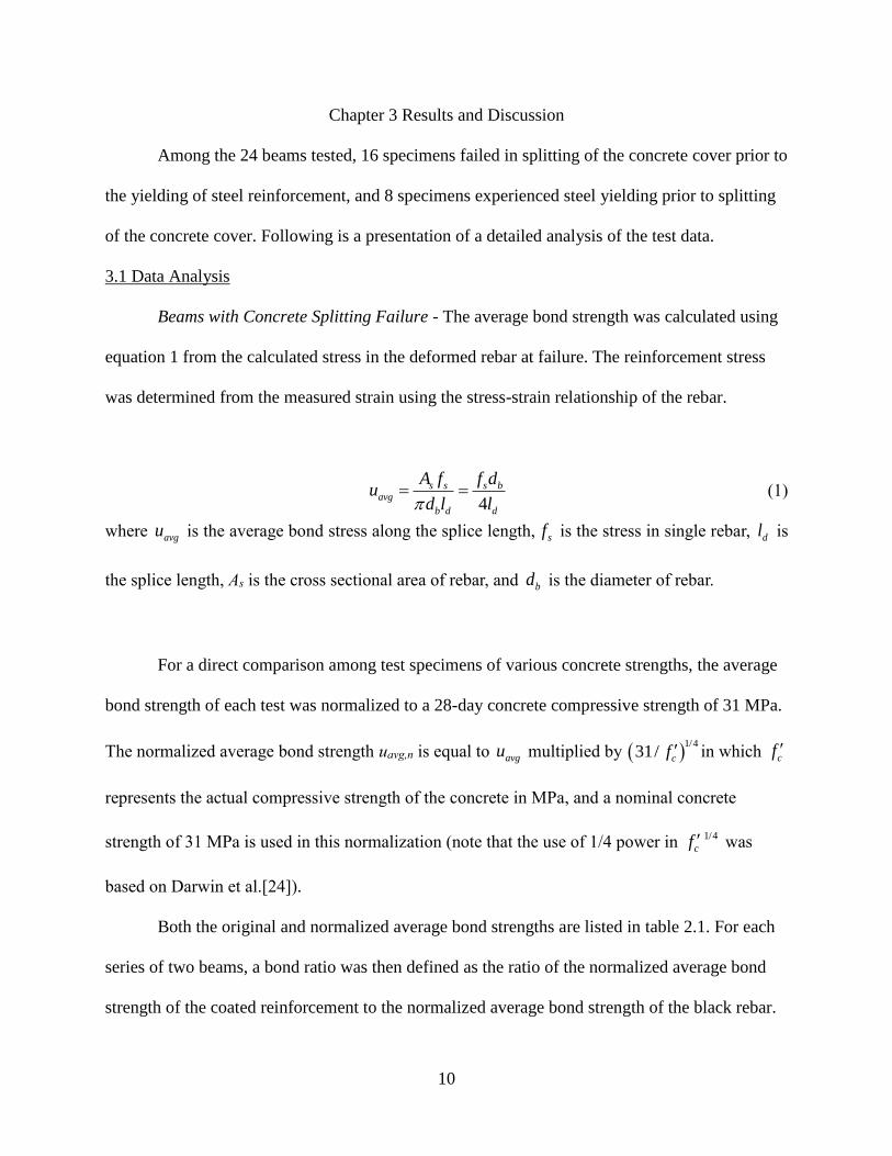
Beams with Concrete Splitting Failure - The average bond strength was calculated using
equation 1 from the calculated stress in the deformed rebar at failure. The reinforcement stress
was determined from the measured strain using the stress-strain relationship of the rebar.
4
s s s bavg
b d d
A f f du
d l l (1)
where avgu is the average bond stress along the splice length, sf is the stress in single rebar, dl is
the splice length, As is the cross sectional area of rebar, and bd is the diameter of rebar.
For a direct comparison among test specimens of various concrete strengths, the average
bond strength of each test was normalized to a 28-day concrete compressive strength of 31 MPa.
The normalized average bond strength uavg,n is equal to avgu multiplied by 1/4
31/ cf in which cf
represents the actual compressive strength of the concrete in MPa, and a nominal concrete
strength of 31 MPa is used in this normalization (note that the use of 1/4 power in 1/4
cf was
based on Darwin et al.[24]).
Both the original and normalized average bond strengths are listed in table 2.1. For each
series of two beams, a bond ratio was then defined as the ratio of the normalized average bond
strength of the coated reinforcement to the normalized average bond strength of the black rebar.

11
The ultimate load (Pu) and its corresponding deflection (Δ0) for each beam are also included in
table 2.1.
Beam with Steel Yielding Prior to Concrete Splitting - For series F, G, and L, steel
yielding occurred prior to the splitting of the concrete cover in the splice region. The average
bond strength was also calculated with equation 1.
3.2 Crack Pattern and Failure Details
Beams with Concrete Splitting Failure - Series A-E with No.19 reinforcement and series
I-K with No.25 reinforcement all failed in concrete splitting prior to yielding of the steel
reinforcement. The failure mode included concrete splitting both on the top and side covers of
the beam in the splice region. Flexural cracks were initiated at various locations along the tension
side and within the constant moment region of the beams. Figures 3.1 and 3.2 show two typical
crack patterns on the top/tension face of the concrete cover in the splice region of the tested
beams with coated and black rebar when lateral confinement was not provided in the splice
region. The number given along each crack represents the load at which the crack was extended.
It can be seen from figures 3.1 and 3.2 that the specimens with enamel-coated reinforcement
appeared to have more transverse flexural cracks developed in the splice region, but clearly
delayed the formation of longitudinal splitting cracks. The beams suddenly failed immediately
after the longitudinal splitting cracks appeared on the top/tension face.

12
(a) 6B12N
(b) 6C12N
Figure 3.1 Crack pattern in constant moment region of series A
609.6
mm
0
mm 914.4
mm
304.8
mm
0
mm
304.8
mm
1k 1000 N
C L
26.7k
26.7k 26.7k
89k 48.95k
44.5k
89k
609.6
mm 0
mm
925.2
mm 304.8
mm
C L
0
mm
304.8
mm
26.7k 44.5k
44.5k
26.7k 26.7k
102.35k
102.35k
1k 1000 N
53.4k
66.75k
53.4k 279.4k

13
(a) 8B36N
(b) 8C36N
Figure 3.2 Crack pattern in constant moment region of series I
As the displacement increased, the concrete splitting cracks in the splice region were
significantly widened, and the concrete cover detached and could be easily removed without
disturbing the surface condition of the rebar. For beams with enamel-coated reinforcement as,
illustrated in figure 3.3, significant concrete residuals remained on the coating surface over the
splice length, indicating a significant chemical adhesion between the coating and concrete.
1 k 1000 N
C L
0
mm
304.8
mm
609.6
mm
0
mm
914.4
mm
304.8
mm
169.1k
169.1k
35.6k
66.75k
57.85k 71.2k
89k
93.45k 71.2k
106.8k
35.6k
53.4k
C L
0
mm
304.8
mm
609.6
mm
0
mm 914.4
mm
304.8
mm
195.8k
44k
35.6k
66.75k
66.75k 71.2k
97.9k 102.35k
71.2k
124.6k 71.2k
35.6k
44.5k
53.4k
1k 1000 N

14
Concrete crushing was also evident in the vicinity of rebar ribs, which indicated that the
specimen failed in Mode 2 splitting [25]. On the contrary, for beams with black reinforcement
(fig. 3.4), concrete residuals were present only at the rib-front areas due to steel bearing on the
concrete.
Figure 3.3 Crack pattern in constant moment region of series I

15
Figure 3.4 Crack pattern in constant moment region of series I
Beams with Steel Yielding Prior to Concrete Splitting - Series F-H with No.19 rebar and
series L with No.25 rebar experienced limited steel yielding before the concrete cover split on
the top and side faces of the beams. Like the previous series of specimens that failed in concrete
splitting, flexural cracks were initiated in the splice region; both local concrete crushing at the
rib-front area of black bars and strong adhesion between the enamel-coated rebar and concrete
were observed. However, the beams with black steel reinforcement had fewer transverse flexural
cracks in comparison with the previous series.
Overall, the beam specimens with coated rebar appeared to have a greater number of
flexural cracks than those with black rebar. This observation indicated that the enamel-coated
rebar can transfer stress more effectively due to a stronger steel-concrete bond. However, most
flexural cracks of the two specimens with and without enamel coating occurred at similar
locations of rebar termination.
16
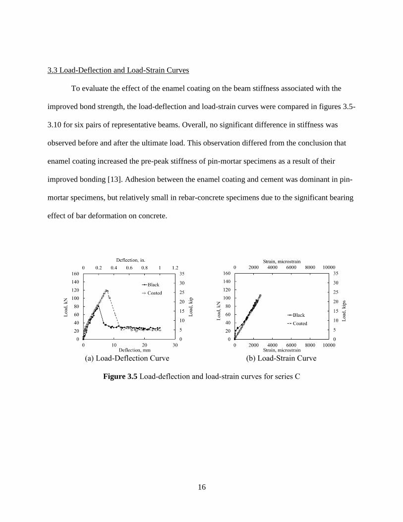
3.3 Load-Deflection and Load-Strain Curves
To evaluate the effect of the enamel coating on the beam stiffness associated with the
improved bond strength, the load-deflection and load-strain curves were compared in figures 3.5-
3.10 for six pairs of representative beams. Overall, no significant difference in stiffness was
observed before and after the ultimate load. This observation differed from the conclusion that
enamel coating increased the pre-peak stiffness of pin-mortar specimens as a result of their
improved bonding [13]. Adhesion between the enamel coating and cement was dominant in pin-
mortar specimens, but relatively small in rebar-concrete specimens due to the significant bearing
effect of bar deformation on concrete.
(a) Load-Deflection Curve (b) Load-Strain Curve
Figure 3.5 Load-deflection and load-strain curves for series C

17
(a) Load-Deflection Curve (b) Load-Strain Curve
Figure 3.6 Load-deflection and load-strain curves for series D
(a) Load-Deflection Curve (b) Load-Strain Curve
Figure 3.7 Load-deflection and load-strain curves for series E
(a) Load-Deflection Curve (b) Load-Strain Curve
Figure 3.8 Load-deflection and load-strain curves for series I

18
(a) Load-Deflection Curve (b) Load-Strain Curve
Figure 3.9 Load-Deflection and Load-Strain Curves for Series K
(a) Load-Deflection Curve (b) Load-Strain Curve
Figure 3.10 Load-Deflection and Load-Strain Curves for Series L
Beams with Concrete Splitting Failure – As shown in figures 3.5(a) and 3.8(a), as the
beams were displaced gradually, the load increased linearly and rapidly at small displacement,
continued to increase linearly at a reduced stiffness after concrete cracking, suddenly dropped at
concrete splitting, and finally remained at a certain level mainly due to a friction effect. In
comparison to the beams with black rebar, the beams with enamel-coated rebar endured larger
deformation and a higher load due to the increased adhesion and friction of coated rebar in

19
concrete. As illustrated by the load-strain curves in figures 3.5(b) and 3.8 (b), no steel yielding
was observed in the steel rebar.
Beams with Steel Yielding Prior to Concrete Splitting - With sufficient splice lengths,
yield strength was eventually developed in the spliced bars, such as series F, G, H, and L. As
represented by figure 3.10(a), a typical plateau was observed in the load-deflection curve. When
the maximum load occurred after rebar yielding, the beams in each series had the same ultimate
load resistance. The load-strain curves also confirmed the yielding of the steel rebar. In these
cases, the maximum strain of the beams with enamel-coated rebar is significantly larger than that
of black rebar, which indicates a more effective transfer of stress from the concrete to the coated
steel rebar. For beams with slightly shorter splice lengths, as illustrated in figure 3.6(a) for series
E, a limited degree of inelastic deformation was developed after initial yielding and the effect of
the coating was insignificant.
Transition in Failure Modes - As the splice length increased, more stress was transferred
from the concrete to the reinforcement. At the same splice length, the stress in the coated rebar
was significantly higher than that of the black rebar. For example, figure 3.6(a) indicated that the
maximum stress in the No.19 coated rebar spliced 406 mm in the confined beams was close to
the yield strength, and the load-deflection curve showed the beginning of a yielding plateau. The
load-strain curves in figure 3.6(b) confirmed the onset of initial yielding in the enamel-coated
reinforcing rebar. However, the stress in the corresponding No.19 black rebar was significantly
lower than the yield strength, and the load-deflection curve showed a sudden drop of load as
concrete splitting occurred. Therefore, the enamel coating changed the structural behavior from a
brittle concrete splitting failure to a nearly ductile steel yielding failure. A similar conclusion can

20
be drawn for the No.25 rebar spliced 1092 mm in the unconfined beams as illustrated in figure
3.9(a, b).
3.4 Bond Ratio
Splice Length Effect - The bond ratio for each series of two beams in pairs was calculated by
dividing the ultimate bond strength of the enamel-coated rebar by that of the black rebar. As
shown in figure. 3.11, the calculated bond ratios were plotted as a function of splice length over
rebar diameter ratio (ld /db) for different confinement conditions. It can be clearly observed from
figures 3.11 and table 2.1 that the bond ratios for all pairs of the beams tested in this
experimental program are greater than or equal to 1.0. The bond ratio first increases at short
splice lengths from 1.0 to a maximum value, such as 1.44, and then decreases to 1.0 when steel
yielding occurs with long splice lengths. In theory, as the splice length approaches to zero, the
bond strength is dominated by the strength of concrete between the two spliced rebar, becomes
independent of coating conditions, and thus approaches 1.0. As indicated in figures 3.5, 3.6 and
3.8 for series C, D, and I beams, the maximum bond ratio corresponds to the maximum elastic
stress that can be developed in the coated rebar, and lies in the range of 20 to 35 in splice length
over rebar diameter ratio (ld /db).
Confinement Effect – As shown in figure 3.11, beams with confined longitudinal rebar by
transverse stirrups have lower bond ratios, indicating a relatively smaller coating effect of a
confined splice joint. This is because confinement increases the bond strength of black rebar
more rapidly than that of enamel-coated rebar. However, as the splice length continued to
increase, the stress in the spliced rebar was close to the yield strength; the effect of confinement
on bond ratio gradually diminished.
21
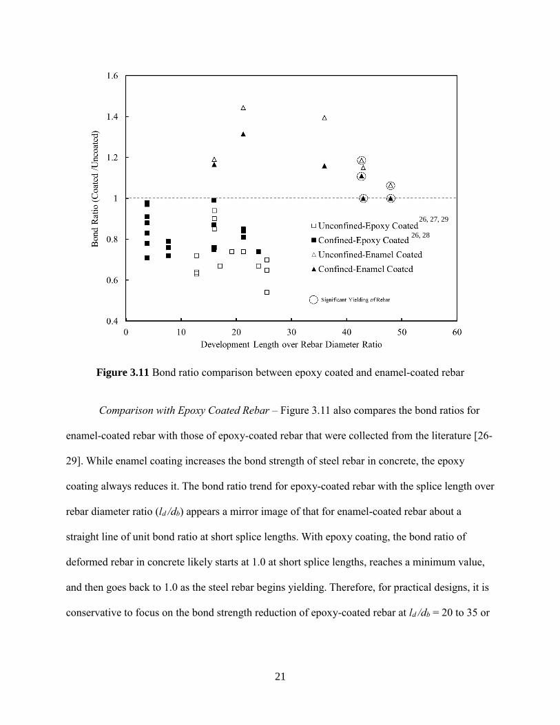
Figure 3.11 Bond ratio comparison between epoxy coated and enamel-coated rebar
Comparison with Epoxy Coated Rebar – Figure 3.11 also compares the bond ratios for
enamel-coated rebar with those of epoxy-coated rebar that were collected from the literature [26-
29]. While enamel coating increases the bond strength of steel rebar in concrete, the epoxy
coating always reduces it. The bond ratio trend for epoxy-coated rebar with the splice length over
rebar diameter ratio (ld /db) appears a mirror image of that for enamel-coated rebar about a
straight line of unit bond ratio at short splice lengths. With epoxy coating, the bond ratio of
deformed rebar in concrete likely starts at 1.0 at short splice lengths, reaches a minimum value,
and then goes back to 1.0 as the steel rebar begins yielding. Therefore, for practical designs, it is
conservative to focus on the bond strength reduction of epoxy-coated rebar at ld /db 20 to 35 or
26, 27, 29
26, 28
22
the bond strength increase of enamel-coated rebar at ld /db 35 to 43, towards initial yielding of
steel rebar. As such, experimental studies on RC beams with long splice lengths are crucial.
3.5 Coating Factor for Enamel-Coated Rebar
To account for the coating effect, a coating factor was simply introduced into the existing
relation between bond strength and development length in current design guidelines and codes
(ACI 408R-03 [30] equation 4-11b, ACI 318-11 [8] equation 12-1, and AASHTO-11 [9] Article
5.11.2.1.1). These design equations were mainly based on elastic rebar data where short splice
lengths were intentionally provided to achieve concrete splitting failures. Therefore, only the test
results associated with the splitting failure in table 2.1 were used in this section. That is, the bond
ratios for series A-D and I-K will be used in the following analysis, as presented in table 3.1.
It should be noted that Class B or C factors were not used in the calculation of bond
strengths using either the AASHTO-11 or ACI 318-11 codes, as these factors are not for strength
considerations, but reflect the brittle failure nature when all the splices are placed at the same
location. The existing design equations from the aforementioned codes are applicable for epoxy-
coated rebar after a coating factor of 1.2 or 1.5 has been introduced. For the enamel-coated rebar,
the average bond ratio in table 3.1 is approximately 1.24, which corresponds to a coating factor
of 1/1.24=0.81. For design purposes, a conservative coating factor of 0.85 on the splice length is
recommended, and its corresponding bond strength increased by an average factor of
1/0.85=1.176 is much less than the value of 1.44 (Series C) achieved at near initial yielding of
the rebar. The design bond strengths after using the design equation from each code multiplied
by a factor of 1.176 are also listed in table 3.1. The means and standard deviations of the
experimental to predicted ratios using various design specifications are presented in figure 3.12.
It can be observed from figure 3.12 that the ACI 408R design equation with the proposed coating

23
factor gives the best prediction to the experimental data on both the average and standard
deviation. Therefore, the development length for enamel-coated rebar splices can be obtained
using the ACI 408R equation with a coating factor of 0.85.
Figure 3.12 Ratio of test to predicted for series associated with splitting failure

24
Table 3.1 Bond Stress Prediction with Various Design Equations
Series Notation uavg
MPa
utest,n
MPa
Bond
Ratio
ACI 408R-
03 with 0.85
MPa
ACI 318-11
with 0.85
MPa
AASHTO-11
with 0.85
MPa
Test to
Predicated
ACI 408R-03
Test to
Predicated
ACI 318-11
Test to
Predicated
AASHTO-11
A 6C12N 5.33 5.49 1.16 3.59 2.05 3.24 1.528 2.674 1.691
B 6C12T 6.47 6.67 1.14 5.09 3.42 2.43 1.311 1.950 2.740
C 6C16N 4.49 4.63 1.44 3.12 2.05 3.24 1.484 2.255 1.426
D 6C16T 5.20 5.20 1.31 4.61 3.42 2.43 1.128 1.521 2.138
I 8C36N 3.33 3.43 1.35 2.26 2.14 2.87 1.522 1.607 1.195
J 8C36T 3.51 3.51 1.10 2.87 2.87 2.43 1.222 1.222 1.443
K 8C43N 2.77 2.85 1.15 2.12 2.14 2.41 1.344 1.333 1.184
Average Bond Ratio=1.24
Coating Factor=0.85
Maximum: 1.528 2.674 2.740
Minimum: 1.128 1.222 1.184
Average: 1.339 1.801 1.686
Standard
Deviation: 0.159 0.481 0.528
Coefficient of
Variation: 0.119 0.267 0.313

25
Chapter 4 Conclusions
To evaluate the bond strength of vitreous enamel-coated rebar in normal strength
concrete, 24 beam splice specimens were cast and tested. Based on the experimental results, the
following conclusions can be drawn:
1. Enamel coating increases the bond strength of deformed rebar when spliced in normal
strength concrete. As the splice length increases, the ratio of bond strength between coated rebar
and black rebar first increases from 1.0 to a maximum value of 1.44 and then decreases to 1.0.
The maximum bond strength ratio corresponds to a splice length over rebar diameter ratio of 20
to 35 when the maximum elastic stress is developed in enamel-coated rebar. The bond strength
ratio approaches 1.0 both at zero splice length and at a very long splice length since the bond
strengths in the two cases are governed by concrete splitting and steel yielding, respectively.
2. Confinement provided by transverse stirrups increases the bond strength of black rebar
more rapidly than that of enamel-coated rebar. For enamel-coated rebar, an average of a 10%
increase in bond strength was observed due to the confinement effect for a splice length over
rebar diameter ratio of less than 20. For very long splice lengths, the stress in the spliced rebar
(black or coated) is equal to the yield strength, and the confinement effect thus becomes
negligible.
3. The increase in bond strength due to the coating is reflected mainly in the ultimate load
of the structures or beams tested in this study; it has little or no influence on the pre- and post-
peak stiffness of the beams. It is unlikely that the coating alters the distribution pattern of slip
between the reinforcement and concrete.
4. The beams with coated steel rebar appear to have a greater number of smaller flexural
cracks than those containing black rebar. This observation indicated that the enamel-coated rebar

26
more effectively transfers stress from the concrete to the rebar due to stronger steel-concrete
bonding.
5. Enamel and epoxy coatings respectively increase and reduce the bond strength of
deformed rebar in concrete. For practical designs, conservative coating factors should be
developed in a splice length over rebar diameter ratio of greater than 35 for enamel-coated rebar
and 20 to 35 for epoxy-coated rebar. It is critical to investigate the bond strength of enamel-
coated rebar in concrete with long splice lengths, corresponding to initial yielding of steel rebar.
6. The ACI 408R design equation for splice length with a coating factor of 0.85 is
recommended for design.

27
References
[1]. Treece, R.A., and Jirsa J.O., “Bond Strength of Epoxy-Coated Reinforcing Bars,”
PMFSEL Report No.87-1, Phil M. Ferguson Structural Engineering Laboratory,
University of Texas at Austin, 85 pp., Jan. 1985.
[2]. Johnston, D.W. and Zia, P., “Bond Characteristics of Epoxy Coated Reinforcing Bars,”
Report No. FHWA-NC-82-002, Center for Transportation Engineering Studies,
Civil Engineering Department, North Carolina State University, Raleigh, 163 pp.,
1982.
[3]. Choi, O.C., Hadje-Ghaffari, H., Darwin, D., and McCabe, S.L., “Bond of Epoxy-Coated
Reinforcement to Concrete: Bar Parameters,” SL Report 90-1, University of
Kansas Center for Research, Lawrence, 43 pp., Jan. 1990.
[4]. Choi, O.C., Darwin, D., and McCabe, S.L., “Bond Strength of Epoxy-Coated
Reinforcement to Concrete,” SM Report No.25, University of Kansas Center for
Research, Lawrence, 217 pp., July, 1990.
[5]. Choi, O.C., Hadje-Ghaffari, H., Darwin, D., and McCabe, S.L., “Bond of Epoxy-Coated
Reinforcement: Bar Parameters,” ACI Materials Journal, V. 88, No.2, pp. 207-
217, Mar.-Apr., 1990.
[6]. Hadje-Ghaffari, H., Choi, O.C., Darwin, D., and McCabe, S.L., “Bond of Epoxy-Coated
Reinforcement: Cover, Casting Position, Slump, and Consolidation,” ACI
Structural Journal, V. 91 No.1, pp. 59-68, Jan-Feb., 1994.
[7]. Idun, E.K. and Darwin, D., “Bond of Epoxy-coated Reinforcement: Coefficient of
Friction and Rib Face Angle,” ACI Structural Journal, V.96, No.4, July-August
1999.
[8]. ACI 318-11, Building Code Requirements for Structural Concrete, American Concrete
Institute (ACI), Farmington Hills, MI, 2011.
[9]. AASHTO-2011, LRFD Bridge Design Specifications, American Association of State
Highways and Transportation Officials (AASHTO), Washington D.C., 2011.
[10]. Tang, F.J., Chen, G.D., Brow, R.K., Volz, J.S., and Koenigstein, M.L., “Corrosion
Resistance of Steel Rebar Coated with Three Types of Enamel,” Corrosion
Science, Vol. 59, pp. 157-168, 2012.
[11]. Day, D.C., Weiss, C.A., Malone, P.G., and Hackler, C.L., “Innovative Method of
Bonding Portland Cement Concrete to Steel using a Porcelain Interface,”
Proceedings of Materials Science and Technology (MS&T) Conference,
Westerville, OH, The American Ceramic Society, 2006.

28
[12]. Allison, P.G., Moser, R.D., Weiss Jr., C.A., Malone, P.G., and Morefield, S.W.,
“Nanomechanical and Chemical Characterization of the Interface between
Concrete, Glass-ceramic Bonding Enamel and Reinforcing Steel,” Building and
Construction Materials, Vol. 37, pp.638-644, 2012.
[13]. Yan, D.M., Reis, S., Tao, X., Chen, G.D., Brow, R.L., and Koenigstein, M.L., “Effect of
Chemically Reactive Enamel Coating on Bonding Strength at Steel/Mortar
Interface,” Construction and Building Materials, Vol. 28, pp.512-518, Mar. 2012.
[14]. Wu, C.L., Chen, G.D., Volz, J.S., Brow, R.K., and Koenigstein, M.L., “Local Bond
Strength of Vitreous Enamel Coated Rebar to Concrete,” Construction and
Building Materials, V. 35, pp. 428-439, Oct. 2012.
[15]. Tepfers, R., “A Theory of Bond Applied to Overlapped Tensile Reinforcement Splices
for Deformed Bars,” Publication No. 73:2, Division of Concrete Structures,
Charlmers University of Technology, Goteborg, 328 pp.,1973.
[16]. Orangun, C.O., Jirsa, J.O., and Breen, J.E., “A Reevaluation of Test Data on
Development Length and Splices,” ACI Journal, Vol.74, No.3, pp. 114-122.,
1977.
[17]. Canbay, E. and Frosch, R.J., “Bond Strength of Lap-Spliced Bars,” ACI Structural
Journal, V. 102, No. 4, pp. 605-614., July-August 2005.
[18]. Darwin, D., McCabe, S.L., Idun, E.K., and Schoenekase, S.P., “Development Length
Criteria: Bars not Confined by Transverse Reinforcement,” ACI Structural
Journal, V. 89, No. 6, pp. 709-720, Nov.-Dec., 1992.
[19]. Zuo, J. and Darwin, D., “Splice Strength of Conventional and High Relative Rib Area
Bars in Normal and High-Strength Concrete,” ACI Structural Journal, V. 97, No.
4, pp. 630-641., July-August 2000.
[20]. Esfahani, M.R., and Kianoush, M.R. “Development/Splice Length of Reinforcing Bars.”
ACI Structural Journal, Vol. 102, No. 1, Jan.-Feb. 2005.
[21]. ASTM, Standard Specification for Deformed and Plain Carbon-Steel Bars for Concrete
Reinforcement, American Society of Testing Methods (ASTM), A615/A615M,
2009.
[22]. ASTM, Standard Test Methods and Definitions for Mechanical Testing of Steel Products,
American Society of Testing Methods (ASTM), A370, 2010.
[23]. Weiss, W.J., Guler, K., and Shah, S.P., “An Experimental Investigation to Determine the
Influence of Size on the Flexural Behavior of High Strength Concrete Beams,”
Proceedings of the Fifth International Symposium on the Utilization of High
29
Strength/High Performance Concrete, Sandefjord, Norway, Vol. 1, pp. 709-718,
1999.
[24]. Darwin, D., Tholen, M.L., Idun, E.K., Zuo, J., “Splice Strength of High Relative Rib
Area Reinforcing Bars,” ACI Structural Journal, V. 93, No.3, pp. 95-107, 1996.
[25]. Cairns, J., and Abdullah, R.B., “Bond Strength of Black and Epoxy-Coated
Reinforcement - a Theoretical Approach,” ACI Materials Journal, V.93, No.4,
July-August, 1996.
[26]. Hamad B.S. and Jirsa J.O., “Strength of Epoxy-Coated Reinforcing Bar Splices Confined
with Transverse Reinforcement”, ACI Structural Journal, V. 90, No.1, Jan.-Feb.,
pp. 77-88, 1993.
[27]. Treece, R. A., and Jirsa J.O., “Bond Strength of Epoxy-Coated Reinforcing Bars”, ACI
Materials Journal, V. 86, No. 2, Mar.-Apr., 1989. pp. 167-174.
[28]. DeVries, R.A. and Moehle J.P., “Lap Splice Strength of Plain and Epoxy-Coated
Reinforcement”, Department of Structure Engineering, Mechanics, and Materials,
School and Civil Engineering, University of California at Berkeley, 1989, 117 pp.
[29]. Choi O.C., Hadje-Ghaffari H., Darwin D., and McCabe S. L., “Bond of Epoxy-Coated
Reinforcement to Concrete: Bar Parameter,” University of Kansas Transportation
Center, Report No. 90-1, Jan. 1990, 43pp.
[30]. ACI 408R-03., Bond and Development of Straight Reinforcing Bars in Tension,
American Concrete Institute (ACI), Farmington Hills, MI, 2003.
Related Documents