Civil Engineering Studies Transportation Engineering Series No. 127 Traffic Operations Lab Series No. 7 UILU-ENG-2003-2007 ISSN-0917-9191 Evaluation of UPS for Intersection Traffic Signals with LEDs: Findings for Myers PB-1250PC UPS By Madhav V. Chitturi Rahim F. Benekohal A study conducted by Traffic Operations Laboratory Department of Civil and Environmental Engineering University of Illinois at Urbana-Champaign Prepared for Illinois Department of Transportation December 2003

Welcome message from author
This document is posted to help you gain knowledge. Please leave a comment to let me know what you think about it! Share it to your friends and learn new things together.
Transcript

Civil Engineering Studies Transportation Engineering Series No. 127 Traffic Operations Lab Series No. 7
UILU-ENG-2003-2007
ISSN-0917-9191
Evaluation of UPS for Intersection Traffic Signals with LEDs:
Findings for Myers PB-1250PC UPS
By Madhav V. Chitturi Rahim F. Benekohal A study conducted by Traffic Operations Laboratory Department of Civil and Environmental Engineering University of Illinois at Urbana-Champaign Prepared for Illinois Department of Transportation December 2003

ii
Technical Report Documentation Page
1. Report No,
FHWA-IL/UI-TOL-7 2. Government Accession No.
3. Recipient's Catalog No
5. Report Date
December 15, 2003 6. Performing Organization Code
4. Title and Subtitle
Evaluation of UPS for Intersection Traffic Signals with LED: Findings for Myers PB-1250PC UPS
7. Author(s)
Madhav V. Chitturi and Rahim F. Benekohal
8. Performing Organization Report No.
UILU-ENG-2003-2007
9. Performing Organization Name and Address
10. Work Unit (TRAIS) 11. Contract or Grant No.
Department of Civil and Environmental EngineeringUniversity of Illinois at Urbana-Champaign 205 N. Mathews Ave. Urbana, Illinois 61801
13. Type of Report and Period Covered
Project Report 2002-2003
12. Sponsoring Agency Name and Address
The Illinois Department of Transportation
14. Sponsoring Agency Code
15. Supplementary
16. Abstract Uninterruptible Power Supply (UPS) systems are used to power the intersection traffic signals that have Light Emitting Diode (LED) signal modules, in case of a power failure. The objective of this study was to test the PB-1250PC UPS manufactured by Myers Power Products and verify if it meets the Illinois DOT’s specification for UPS. Multiple tests with full load (approximately 700 W) and partial loads (flashing reds with about 350W) were conducted at room temperature to determine charge and discharge times. The time to fully charge the batteries was on average 14hrs 17min. The UPS powered a full load for 2hrs 15mins. When powering a full load, the UPS took 1hr 8min to reach 40% battery level. After reaching the 40% level, the UPS powered the flashing reds for 1hr 46min. Myers PB-1250PC UPS meets the majority of the IDOT Specification requirements. It has three major and some minor shortcomings that can be corrected to satisfy all IDOT Specification requirements. The major shortcomings of this model are: the model does not have a NO and NC contact closure for indicating inverter/charger failure: the manufacturer gives a 48 hr burn-in period to each unit instead of 100 hrs required by IDOT specification, the fan in the battery cabinet runs on 48VDC instead of AC power.
17. Key Words Uninterruptible Power Supply for Intersections, UPS, Intersection Traffic Signals, LED Signal Modules, Battery Back up System for Traffic Lights, BBS.
18. Distribution Statement
19. Security Classif. (of this report)
Unclassified
20. Security Classif. (of this page)
Unclassified
21. No. of Pages
17
22. Price
`Form DOT F 1700.7 (8-72) Reproduction of completed page authorized

iii
Acknowledgment and Disclaimer
This study was conducted by the Traffic Operations Laboratory (TOL) at the University of Illinois at Urbana-Champaign. The Illinois Department of Transportation sponsored the study. The contents of this report reflect the views of the authors who are responsible for the facts and accuracy of the data presented herein. The contents do not reflect the official views or policies of the Illinois Department of Transportation. This report does not constitute a standard, specification, or regulation.

iv
TABLE OF CONTENTS
OBJECTIVE ..................................................................................................................... 1
METHODOLOGY ........................................................................................................... 1 COMPANY LITERATURE...................................................................................................... 1 QUESTIONS FROM MANUFACTURERS.................................................................................. 1 VISUAL INSPECTION .......................................................................................................... 2 LABORATORY EXPERIMENT ................................................................................................ 2
NO and NC Relay Contact Closures........................................................................... 2 Switching from AC to UPS and back:......................................................................... 2 Discharge and Recharge Times .................................................................................. 3
TEST RESULTS ............................................................................................................... 5
SUMMARY OF FINDINGS .......................................................................................... 10
APPENDIX A.................................................................................................................. 11

1
OBJECTIVE Myers Power Products a prospective supplier of UPS for Illinois Department of Transportation (IDOT) provided one PB-1250PC UPS system for evaluation. The objective of this study is to test the UPS model provided by the manufacturers and see whether it meets the Specification for UPS developed by IDOT. The evaluation was conducted at the Traffic Operations Lab at the University of Illinois. This report discusses the methodology for testing and the interim results of the evaluation of the PB-1250PC unit. The manufacturer has also provided a unit of PB2000ITS, which is being evaluated currently. The results of that evaluation will be added to the report.
METHODOLOGY IDOT has developed an interim UPS Specification that is modeled after the CalTrans Specification. Based on the discussions with IDOT representatives, the various requirements of (clauses) the UPS Specification were classified into four categories: • Information that is in company literature • Questions asked from manufacturers/suppliers • Visual inspection of the unit • Laboratory experiment Appendix A shows the category in which each of the clauses was placed.
CCoommppaannyy LLiitteerraattuurree The manufacturer’s literature was reviewed to see to what degree the literature claims that the requirements of the Specification are met. In general the clauses which could not be easily verified in the Traffic Operations Laboratory were classified under this category. For example, Operating temperature for both the inverter/power transfer relay and manual bypass switch shall be -37 °C to +74 °C (1.4 in IDOT Specification). For all the clauses grouped under this category it was decided that literature provided by the company would be used for verification. The literature provided by the companies was studied.
QQuueessttiioonnss ffrroomm MMaannuuffaaccttuurreerrss The manufacturers were contacted and requested to provide additional information, if it was not clear from the literature whether their models satisfied certain clauses. Also they were asked to provide certifications for the claims made in their literature, if available. The clauses in section 5 of the Specification deal with the Quality Assurance program, design qualification testing and Production quality control testing employed by the

2
manufacturers. For example, QA process and test results documentation shall be kept on file for a minimum period of seven years (5.2 in IDOT Specification). Since this information is not public knowledge, it was decided that appropriate questions be sent to the manufacturers to ascertain if they satisfied these clauses. Questions were sent to the manufacturers and their responses have been incorporated in the report.
VViissuuaall IInnssppeeccttiioonn For checking if the UPS met certain clauses of the specification, visual inspection was sufficient. For example, the temperature sensor shall be external to the inverter/charger unit. The temperature sensor shall come with 2 meters (6’6”) of wire (1.6.1 in IDOT Specification). Visual Check was performed on the models and the results were incorporated.
LLaabboorraattoorryy EExxppeerriimmeenntt Certain clauses of the specification could be verified by running simple experiments, with readily available equipment, at the Traffic Operations Lab. For example, when the utility line power has been restored at above 105 VAC +/- 2 VAC for more than 30 seconds, the UPS shall dropout of battery backup mode and return to utility line mode (1.11 in IDOT Specification). The experiments performed were essentially of three kinds: relay contact closures, switching from AC to UPS and back, and discharge and recharge times of the batteries.
NO and NC Relay Contact Closures The clauses under this group are related to the four NO and NC relay contact closures that need to be provided and when they would be energized. They are clauses 1.3.1 through 1.3.4. For verifying these clauses the events that would result in energizing the closures were created and it was verified, if indeed the closures were energized. For example, for verifying 1.3.1, while monitoring the relay, AC power was shut down and it was checked if the “On Batt” closure was energized. Similar experiments were performed to verify the rest of the clauses while monitoring the relays.
Switching from AC to UPS and back: The clauses under this group specify under what conditions the UPS should bypass/return to the utility power. Clauses 1.8, 1.11 and 1.12 come under this category. A variable transformer was used for creating the necessary modifications to the AC voltage and it was verified if the UPS performed as it is supposed to.
3
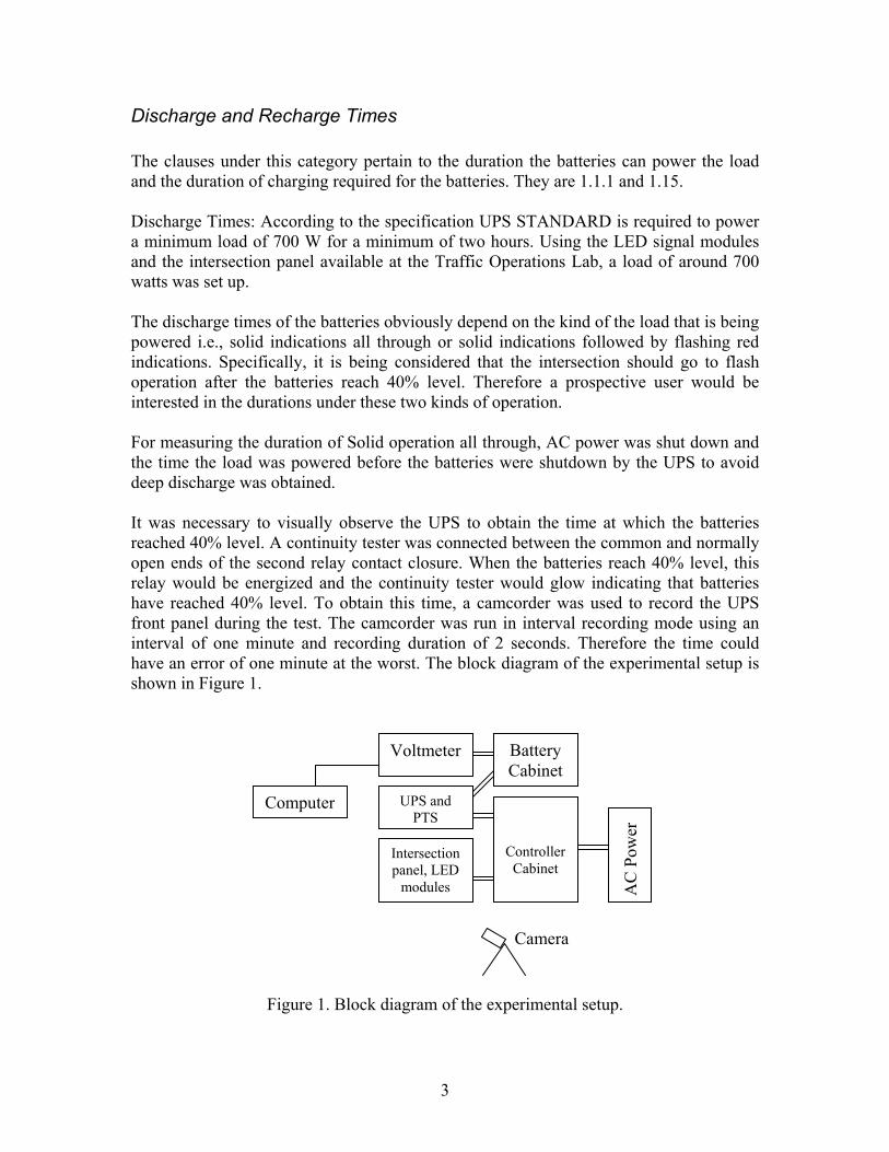
Discharge and Recharge Times The clauses under this category pertain to the duration the batteries can power the load and the duration of charging required for the batteries. They are 1.1.1 and 1.15. Discharge Times: According to the specification UPS STANDARD is required to power a minimum load of 700 W for a minimum of two hours. Using the LED signal modules and the intersection panel available at the Traffic Operations Lab, a load of around 700 watts was set up. The discharge times of the batteries obviously depend on the kind of the load that is being powered i.e., solid indications all through or solid indications followed by flashing red indications. Specifically, it is being considered that the intersection should go to flash operation after the batteries reach 40% level. Therefore a prospective user would be interested in the durations under these two kinds of operation. For measuring the duration of Solid operation all through, AC power was shut down and the time the load was powered before the batteries were shutdown by the UPS to avoid deep discharge was obtained. It was necessary to visually observe the UPS to obtain the time at which the batteries reached 40% level. A continuity tester was connected between the common and normally open ends of the second relay contact closure. When the batteries reach 40% level, this relay would be energized and the continuity tester would glow indicating that batteries have reached 40% level. To obtain this time, a camcorder was used to record the UPS front panel during the test. The camcorder was run in interval recording mode using an interval of one minute and recording duration of 2 seconds. Therefore the time could have an error of one minute at the worst. The block diagram of the experimental setup is shown in Figure 1.
Figure 1. Block diagram of the experimental setup.
Camera
Controller Cabinet
Battery Cabinet
UPS and PTS
Intersection panel, LED
modules
Voltmeter
Computer
AC
Pow
er

4
Once the batteries reached the 40 % level, the intersection was put on flash and the time the flashing load was powered before the batteries were shutdown by the UPS was obtained. Under flashing conditions the load was approximately half of the full load. Therefore it would be expected that the batteries would power the flashing load for approximately twice the time they would have powered the full load. Using this concept, from this data the duration the batteries would have powered a full load can be estimated. If the time to reach 40% battery level is called t1 and flashing duration after reaching 40% battery level is called t2, the duration the batteries would have powered a full load (call it tf) can be estimated using the following relationship. tf = t1 + t2/2 The average of these estimated values is compared with the average duration the batteries powered the full load. If these two numbers are close, that would further increase the confidence in the results of these tests. Recharge times: After every discharge experiment, the batteries were put to charge. While the batteries were being charged their voltage was monitored using a voltmeter that could log in the voltage readings into a computer. Once the batteries are fully charged, the voltage of the batteries would stabilize. Using the voltage data logged in to the computer by the voltmeter, the time for fully recharging the batteries was obtained. It is expected that there would be some variability in the discharge and recharge times of the batteries. Therefore multiple tests are required to ascertain if the systems meet the specifications. Several tests were performed for obtaining the discharge and recharge times of the batteries at room temperature. Based on a 90 % confidence level, sample size and the variance in the test results the error in the estimate was obtained. It was found that in all the cases the error was significantly less than the tolerable error. Therefore further testing was not conducted. The results of these tests are discussed in the “Test Results” section of the report. To compare the mean values returned by the tests to the specification requirements, t-tests were performed. The test associates a confidence level with which one can conclude that the mean value is greater or lesser than the specification requirement. The findings of the evaluation are presented in Appendix A. For each clause of the specification, “Does it meet the spec” column indicates if the UPS satisfies the requirements of the specification. In the course of the evaluation it was found that there were several instances when the answer to the question “Does it meet the specification?” is not a straightforward Yes or No. For this reason, based on our discussions with IDOT representatives, the responses in this column could be “Yes”, “No”, “Yes*” and “No*”. Yes and No clearly indicate that the system satisfies or does not satisfy the specification respectively. Yes* and No* indicate that the system satisfies or does not satisfy with
5
some reservation. Please read the “Comments” column for explanation of the specific answer.
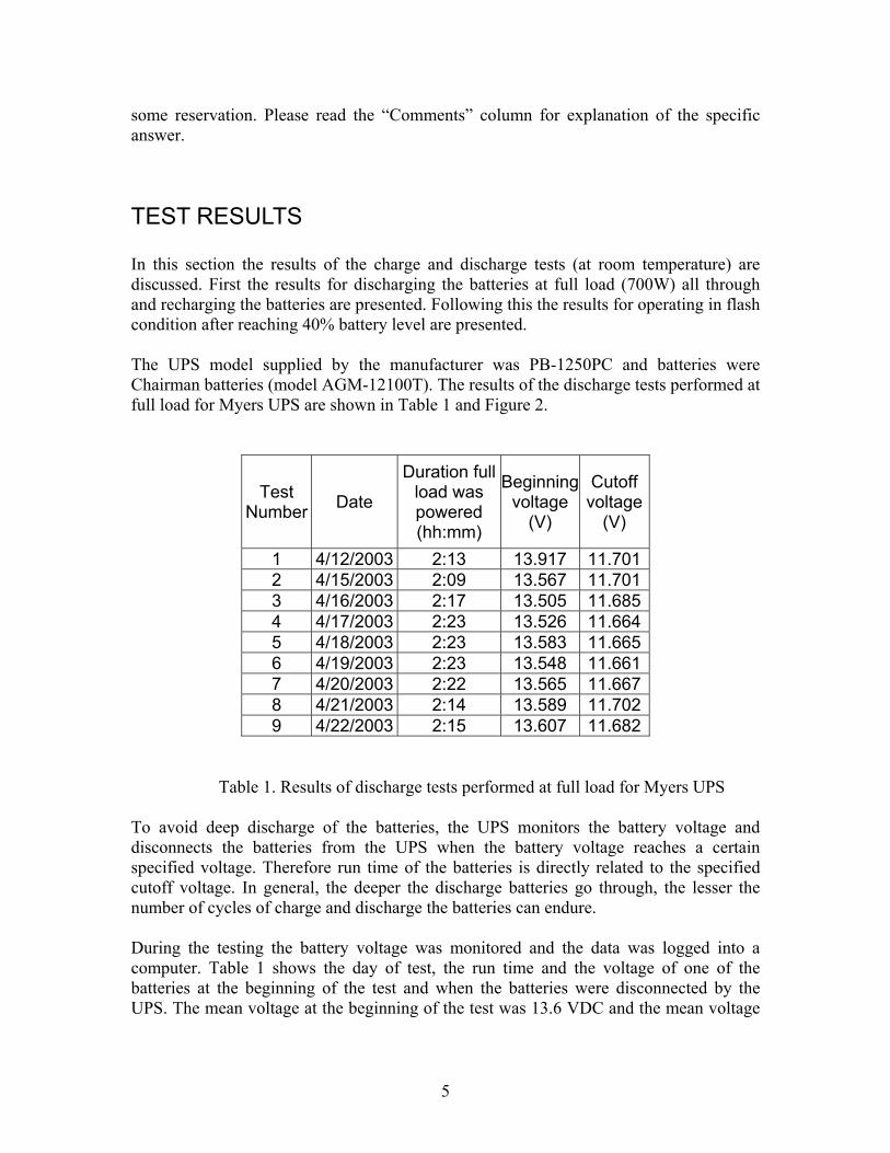
TEST RESULTS In this section the results of the charge and discharge tests (at room temperature) are discussed. First the results for discharging the batteries at full load (700W) all through and recharging the batteries are presented. Following this the results for operating in flash condition after reaching 40% battery level are presented. The UPS model supplied by the manufacturer was PB-1250PC and batteries were Chairman batteries (model AGM-12100T). The results of the discharge tests performed at full load for Myers UPS are shown in Table 1 and Figure 2.
Test Number Date
Duration full load was powered (hh:mm)
Beginning voltage
(V)
Cutoff voltage
(V)
1 4/12/2003 2:13 13.917 11.701 2 4/15/2003 2:09 13.567 11.701 3 4/16/2003 2:17 13.505 11.685 4 4/17/2003 2:23 13.526 11.664 5 4/18/2003 2:23 13.583 11.665 6 4/19/2003 2:23 13.548 11.661 7 4/20/2003 2:22 13.565 11.667 8 4/21/2003 2:14 13.589 11.702 9 4/22/2003 2:15 13.607 11.682
Table 1. Results of discharge tests performed at full load for Myers UPS To avoid deep discharge of the batteries, the UPS monitors the battery voltage and disconnects the batteries from the UPS when the battery voltage reaches a certain specified voltage. Therefore run time of the batteries is directly related to the specified cutoff voltage. In general, the deeper the discharge batteries go through, the lesser the number of cycles of charge and discharge the batteries can endure. During the testing the battery voltage was monitored and the data was logged into a computer. Table 1 shows the day of test, the run time and the voltage of one of the batteries at the beginning of the test and when the batteries were disconnected by the UPS. The mean voltage at the beginning of the test was 13.6 VDC and the mean voltage
6
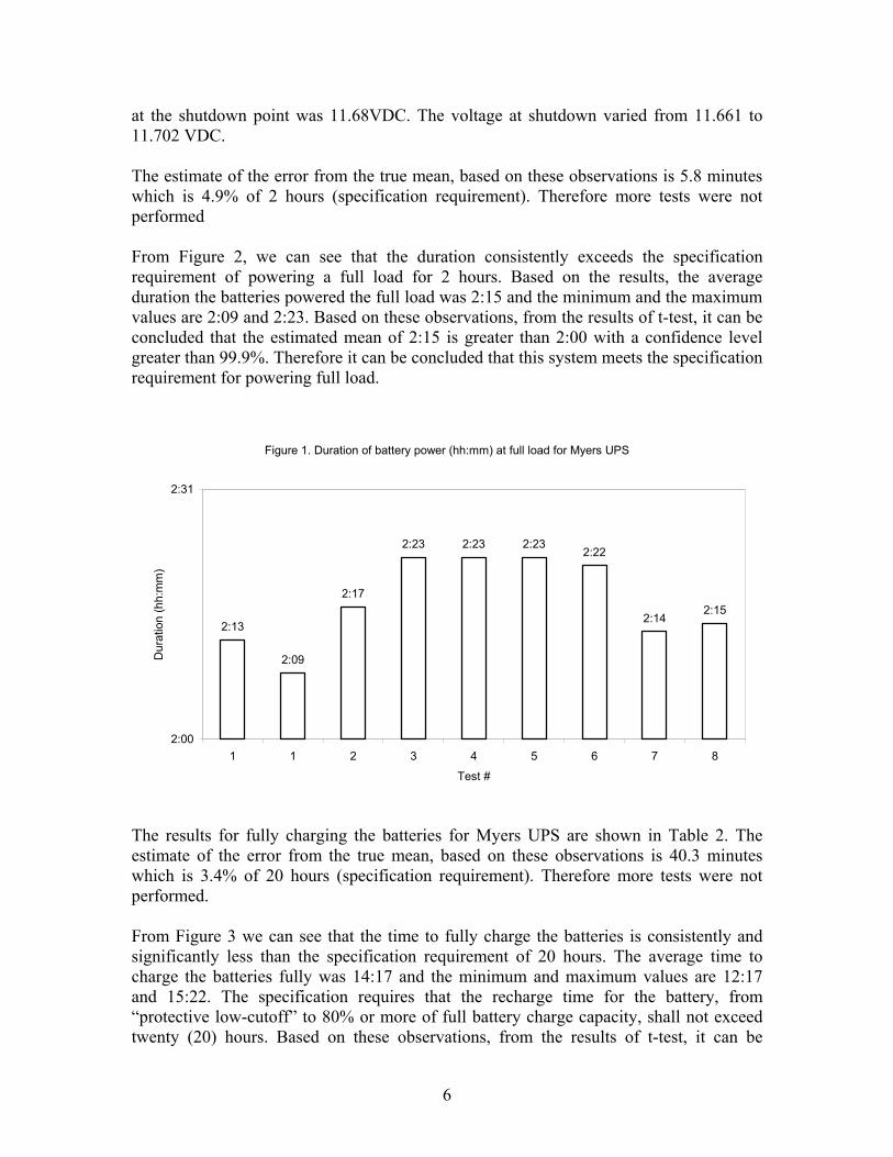
at the shutdown point was 11.68VDC. The voltage at shutdown varied from 11.661 to 11.702 VDC. The estimate of the error from the true mean, based on these observations is 5.8 minutes which is 4.9% of 2 hours (specification requirement). Therefore more tests were not performed From Figure 2, we can see that the duration consistently exceeds the specification requirement of powering a full load for 2 hours. Based on the results, the average duration the batteries powered the full load was 2:15 and the minimum and the maximum values are 2:09 and 2:23. Based on these observations, from the results of t-test, it can be concluded that the estimated mean of 2:15 is greater than 2:00 with a confidence level greater than 99.9%. Therefore it can be concluded that this system meets the specification requirement for powering full load.
Figure 1. Duration of battery power (hh:mm) at full load for Myers UPS
2:13
2:09
2:17
2:23 2:23 2:232:22
2:142:15
2:00
2:31
1 1 2 3 4 5 6 7 8
Test #
Dur
atio
n (h
h:m
m)
The results for fully charging the batteries for Myers UPS are shown in Table 2. The estimate of the error from the true mean, based on these observations is 40.3 minutes which is 3.4% of 20 hours (specification requirement). Therefore more tests were not performed. From Figure 3 we can see that the time to fully charge the batteries is consistently and significantly less than the specification requirement of 20 hours. The average time to charge the batteries fully was 14:17 and the minimum and maximum values are 12:17 and 15:22. The specification requires that the recharge time for the battery, from “protective low-cutoff” to 80% or more of full battery charge capacity, shall not exceed twenty (20) hours. Based on these observations, from the results of t-test, it can be

7
concluded that the estimated mean of 14:17 is less than 20:00 with a confidence level greater than 99.9%. Therefore this system meets the specification requirement for charging the batteries.
Test Number Date
Charging Time
(hh:mm) 1 4/11/2003 12:40 2 4/12/2003 13:20 3 4/16/2003 14:06 4 4/17/2003 15:07 5 4/18/2003 15:22 6 4/19/2003 15:23 7 4/20/2003 15:20 8 4/21/2003 14:51 9 4/22/2003 14:25
10 7/17/2003 12:17
Table 2. Results for fully charging the batteries for Myers UPS.
Figure 3. Time to fully charge the batteries (hh:mm) for Myers UPS
12:40 13:20
14:06 15:07 15:22 15:23 15:20
14:51 14:25
12:17
0:00
2:30
5:00
7:31
10:01
12:32
15:02
17:33
1 2 3 4 5 6 7 8 9 10Test #
Tim
e to
fully
cha
rge
(hh:
mm
)
8
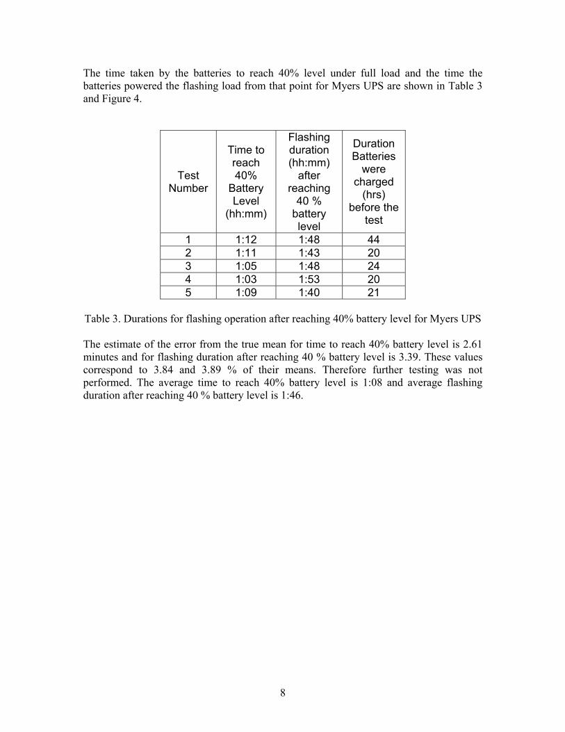
The time taken by the batteries to reach 40% level under full load and the time the batteries powered the flashing load from that point for Myers UPS are shown in Table 3 and Figure 4.
Test Number
Time to reach 40%
Battery Level
(hh:mm)
Flashing duration (hh:mm)
after reaching
40 % battery level
Duration Batteries
were charged
(hrs) before the
test
1 1:12 1:48 44 2 1:11 1:43 20 3 1:05 1:48 24 4 1:03 1:53 20 5 1:09 1:40 21
Table 3. Durations for flashing operation after reaching 40% battery level for Myers UPS
The estimate of the error from the true mean for time to reach 40% battery level is 2.61 minutes and for flashing duration after reaching 40 % battery level is 3.39. These values correspond to 3.84 and 3.89 % of their means. Therefore further testing was not performed. The average time to reach 40% battery level is 1:08 and average flashing duration after reaching 40 % battery level is 1:46.
9
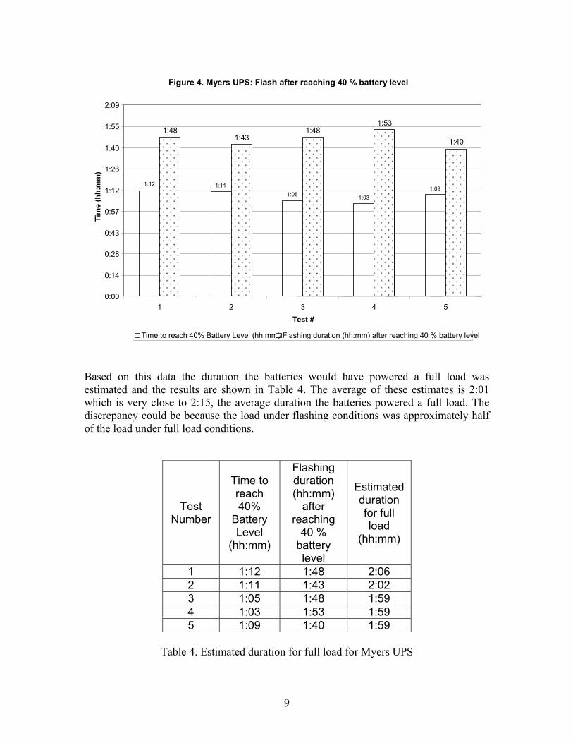
Figure 4. Myers UPS: Flash after reaching 40 % battery level
1:12 1:11 1:05 1:03
1:09
1:48 1:43
1:481:53
1:40
0:00
0:14
0:28
0:43
0:57
1:12
1:26
1:40
1:55
2:09
1 2 3 4 5 Test #
Tim
e (h
h:m
m)
Time to reach 40% Battery Level (hh:mm) Flashing duration (hh:mm) after reaching 40 % battery level Based on this data the duration the batteries would have powered a full load was estimated and the results are shown in Table 4. The average of these estimates is 2:01 which is very close to 2:15, the average duration the batteries powered a full load. The discrepancy could be because the load under flashing conditions was approximately half of the load under full load conditions.
Test Number
Time to reach 40%
Battery Level
(hh:mm)
Flashing duration (hh:mm)
after reaching
40 % battery level
Estimated duration for full load
(hh:mm)
1 1:12 1:48 2:06 2 1:11 1:43 2:02 3 1:05 1:48 1:59 4 1:03 1:53 1:59 5 1:09 1:40 1:59
Table 4. Estimated duration for full load for Myers UPS
10
SUMMARY OF FINDINGS The average run time with full load (approximately 700 W) at room temperature for Myers PB-1250PC was 2 hrs 15 min and the minimum and maximum values were 2 hrs 9 min and 2 hrs 23 min respectively. The mean voltage of a battery at the shutdown point was 11.68VDC. On the average the time to charge the batteries fully at room temperature was 14 hrs 17 min and the charging times ranged from 12 hrs 17 min to 15 hrs 22 min. Statistical tests concluded that for run time at full load and recharge time the Myers PB-1250PC UPS meets the specification requirements. Also it was observed that the UPS took 1 hr 8 min on the average to reach 40% battery level (when operating on full load) and powered flashing reds for 1 hr 46 min more on the average. Details on how Myers PB-1250PC meets each specific requirement of the IDOT Specification is given in Appendix A. The major shortcomings of this model are: this model does not have a NO and NC contact closure for indicating inverter/charger failure. The specification requires that each UPS be given a minimum 100 hr burn-in period to catch any premature failures. However the manufacturer gives a 48 hr burn-in period to each unit. Also the fan in the battery cabinet runs on 48VDC as opposed to the specification requirement of running on AC power. This model has some minor shortcomings such as not providing sufficiently long cables, board-level schematic and wiring diagrams etc. Myers has provided a new model (PB 2000 ITS) for evaluation that has programmable contact closures. The manufacturer claims that PB 2000 ITS can be programmed to indicate inverter/charger failure. This would be verified in the lab. In summary, Myers PB-1250PC UPS meets the majority of the IDOT Specification requirements. It has three major and some minor shortcomings that can be corrected to satisfy all IDOT Specification requirements.
11
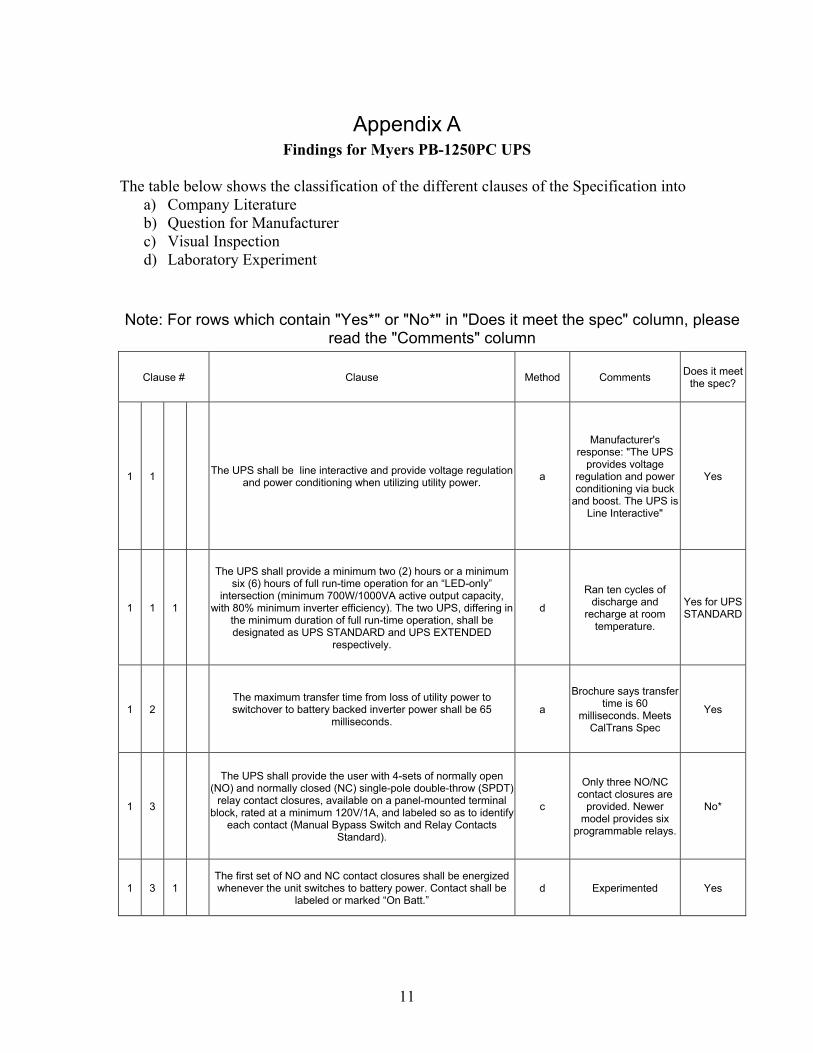
Appendix A Findings for Myers PB-1250PC UPS
The table below shows the classification of the different clauses of the Specification into
a) Company Literature b) Question for Manufacturer c) Visual Inspection d) Laboratory Experiment
Note: For rows which contain "Yes*" or "No*" in "Does it meet the spec" column, please read the "Comments" column
Clause # Clause Method Comments Does it meet the spec?
1 1 The UPS shall be line interactive and provide voltage regulation and power conditioning when utilizing utility power. a
Manufacturer's response: "The UPS
provides voltage regulation and power conditioning via buck
and boost. The UPS is Line Interactive"
Yes
1 1 1
The UPS shall provide a minimum two (2) hours or a minimum six (6) hours of full run-time operation for an “LED-only”
intersection (minimum 700W/1000VA active output capacity, with 80% minimum inverter efficiency). The two UPS, differing in
the minimum duration of full run-time operation, shall be designated as UPS STANDARD and UPS EXTENDED
respectively.
d
Ran ten cycles of discharge and
recharge at room temperature.
Yes for UPS STANDARD
1 2 The maximum transfer time from loss of utility power to switchover to battery backed inverter power shall be 65
milliseconds. a
Brochure says transfer time is 60
milliseconds. Meets CalTrans Spec
Yes
1 3
The UPS shall provide the user with 4-sets of normally open (NO) and normally closed (NC) single-pole double-throw (SPDT)
relay contact closures, available on a panel-mounted terminal block, rated at a minimum 120V/1A, and labeled so as to identify
each contact (Manual Bypass Switch and Relay Contacts Standard).
c
Only three NO/NC contact closures are
provided. Newer model provides six
programmable relays.
No*
1 3 1 The first set of NO and NC contact closures shall be energized whenever the unit switches to battery power. Contact shall be
labeled or marked “On Batt.” d Experimented Yes

12
1 3 2
The second set of NO and NC contact closures shall be energized whenever the battery approaches approximately 40%
of remaining useful capacity. Contact shall be labeled or marked “Low Batt.”
d Experimented Yes
1 3 3 The third set of NO and NC contact closures shall be energized two hours after the unit switches to battery power. Contact shall
be labeled or marked “Timer.” d Experimented Yes
1 3 4 The fourth set of NO and NC contact closures shall be
energized in the event of inverter/ charger failure. Contact shall be labeled or marked “UPS Fail.”
d
Fourth set of NO/NC contact closures not provided in present
model. Newer model provides six
programmable relays.
No*
1 4 Operating temperature for both the inverter/power transfer relay and manual bypass switch shall be -37 °C to +74 °C (-35 °F to
165 °F). a
Brochure indicates the operating range for the
unit as – 37°C to +74°C. Meets CalTrans Spec
Yes
1 5 Both the Power Transfer Relay and Manual Bypass Switch shall be rated at 240VAC/30 amps, minimum. a Verified with the
manufacturer Yes
1 6 The UPS shall use a temperature-compensated battery
charging system. The charging system shall compensate over a range of 2.5 – 4.0 mV/°C or (1.4 – 2.2 mV/°F) per cell.
a Stated on pg. 61of the
Manual. Meets CalTrans Spec
Yes
1 6 1 The temperature sensor shall be external to the inverter/charger unit. The temperature sensor shall come with 2 meters (6.5 ft) of
wire. c Sensor is external.
Wire is 2 inch shorter Yes*
1 7 Batteries shall not be recharged when battery temperature exceeds 50°C ± 3°C (122oF + 5oF). a
Stated on pg. 61of the Manual that batteries will not be charged
when battery temperature exceeds 50 °C +/- 3°C. Meets
CalTrans Spec
Yes
1 8 UPS shall bypass the utility line power whenever the utility line
voltage is outside of the following voltage range: 100VAC to 130VAC (± 2VAC).
d Used a variable
transformer to modify line power
Yes
1 9 When utilizing battery power, the UPS output voltage shall be between 110 VAC and 125 VAC, pure sine wave output, £ 3%
THD, 60Hz ±3Hz. d
Voltage between 110 and 125 V, Frequency
60+/- 3 Hz Yes
1 10 UPS shall be compatible with Illinois DOT’s traffic controller
assemblies utilizing NEMA TS 1 or NEMA TS 2 controllers and cabinet components for full time operation.
d Tested UPS in TS2 Type 1 Cabinet Yes
1 11 When the utility line power has been restored at above 105 VAC
±2 VAC for more than 30 seconds, the UPS shall dropout of battery backup mode and return to utility line mode.
d Used a variable
transformer to modify line power
Yes

13
1 12 When the utility line power has been restored at below 125VAC
±2 VAC for more than 30 seconds, the UPS shall dropout of battery backup mode and return to utility line mode.
d Used a variable
transformer to modify line power
Yes
1 13 UPS shall be equipped to prevent a malfunction feedback to the cabinet or from feeding back to the utility service. a Verified with the
manufacturer Yes
1 14 In the event of inverter/charger failure, the power transfer relay
shall revert to the NC state, where utility line power is reconnected to the cabinet.
d Experimented Yes
1 15 Recharge time for the battery, from “protective low-cutoff” to 80% or more of full battery charge capacity, shall not exceed
twenty (20) hours. d
Ran ten cycles of discharge and
recharge at room temperature.
Yes
2 1 1 Inverter/Charger Unit shall be rack or shelf-mounted. Yes
2 1 2 (Reserved)
2 1 3 All interconnect wiring provided between Power Transfer Relay, Bypass Switch and Cabinet Terminal Service Block shall be no
less than 2 meters (6.5 ft) of #10 AWG wire. c Wire is #14 AWG and
3 inch shorter Yes*
2 1 4 Relay contact wiring provided for each set of NO/NC relay
contact closure terminals shall be 2 meters (6’6”) of #18 AWG wire.
c Wire is #10 AWG Yes*
2 1 5
To ensure interchangeability between all UPS manufacturers, UPS Power Transfer Relay and Manual Bypass Switch shall be
interconnected with Type IV or Type V NEMA cabinets according to the Department standards.
c Yes
2 1 6 (Reserved)
2 2 * ( Reserved) -
2 3 1
Inverter/Charger, Power Transfer Relay and manually operated Bypass Switch shall fit inside a typical fully equipped Type IV or Type V NEMA Cabinet that houses one NEMA TS 1 or NEMA
TS 2 controller.
d Inverter: Yes PTS: Probably no No*
2 3 2
Batteries shall be housed in a NEMA Standard TS 2 rated cabinet, self supported and mounted on the concrete foundation according to the Department standards. This external battery cabinet shall conform to the IDOT Standard Specifications for
the construction and finish of the cabinet.
c
Did not test for the conformance of the
cabinet to IDOT Specification
Yes*
2 3 3 Batteries shall be mounted on individual shelves for the cabinet housing four (4) batteries and two (2) batteries per shelf for the
cabinet housing eight (8) batteries. c
Cabinet provided can accommodate only
four batteries Yes
2 3 4 Four shelves shall be provided. Each shelf shall support a load
of 30 kg (66 lb) minimum for single battery or 60 kg (132 lb) minimum for dual batteries.
c Yes
2 3 5 (Reserved)
2 3 6
Cabinets housing four (4) batteries shall have nominal outside dimensions of width 356 mm (14 in.) depth 229 mm (9 in.) and height within 1143 mm to 1397 mm (45 in. to 55 in.). Cabinets
housing eight (8) batteries shall have nominal outside dimensions of width 711 mm (28 in.) depth 229 mm (9 in.), and height within 1143 mm to 1397 mm (45 in. to 55 in.). Clearance
between shelves shall be a minimum of 254 mm (10 in.).
c Yes
14
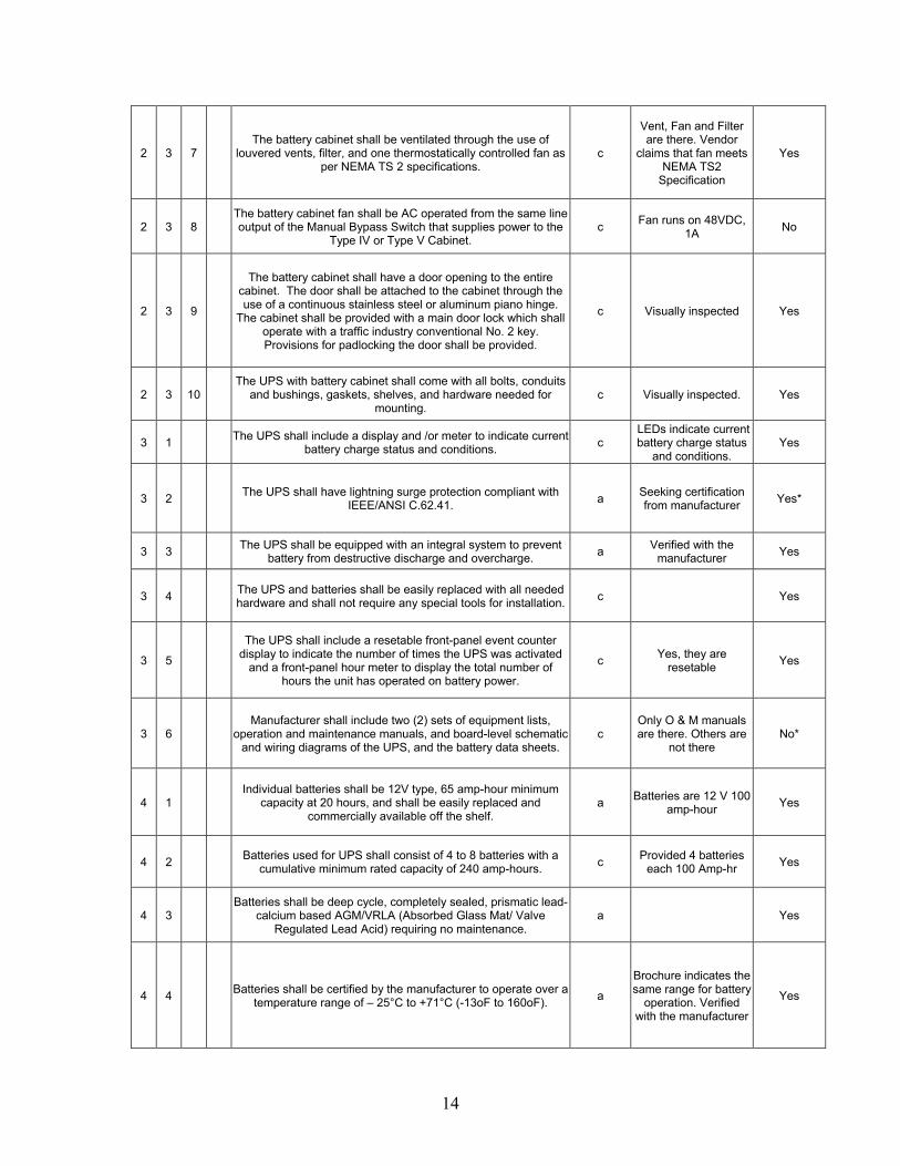
2 3 7 The battery cabinet shall be ventilated through the use of
louvered vents, filter, and one thermostatically controlled fan as per NEMA TS 2 specifications.
c
Vent, Fan and Filter are there. Vendor
claims that fan meets NEMA TS2
Specification
Yes
2 3 8 The battery cabinet fan shall be AC operated from the same line output of the Manual Bypass Switch that supplies power to the
Type IV or Type V Cabinet. c Fan runs on 48VDC,
1A No
2 3 9
The battery cabinet shall have a door opening to the entire cabinet. The door shall be attached to the cabinet through the use of a continuous stainless steel or aluminum piano hinge.
The cabinet shall be provided with a main door lock which shall operate with a traffic industry conventional No. 2 key. Provisions for padlocking the door shall be provided.
c Visually inspected Yes
2 3 10 The UPS with battery cabinet shall come with all bolts, conduits
and bushings, gaskets, shelves, and hardware needed for mounting.
c Visually inspected. Yes
3 1 The UPS shall include a display and /or meter to indicate current battery charge status and conditions. c
LEDs indicate current battery charge status
and conditions. Yes
3 2 The UPS shall have lightning surge protection compliant with IEEE/ANSI C.62.41. a Seeking certification
from manufacturer Yes*
3 3 The UPS shall be equipped with an integral system to prevent battery from destructive discharge and overcharge. a Verified with the
manufacturer Yes
3 4 The UPS and batteries shall be easily replaced with all needed hardware and shall not require any special tools for installation. c Yes
3 5
The UPS shall include a resetable front-panel event counter display to indicate the number of times the UPS was activated
and a front-panel hour meter to display the total number of hours the unit has operated on battery power.
c Yes, they are resetable Yes
3 6 Manufacturer shall include two (2) sets of equipment lists,
operation and maintenance manuals, and board-level schematic and wiring diagrams of the UPS, and the battery data sheets.
c Only O & M manuals are there. Others are
not there No*
4 1 Individual batteries shall be 12V type, 65 amp-hour minimum
capacity at 20 hours, and shall be easily replaced and commercially available off the shelf.
a Batteries are 12 V 100 amp-hour Yes
4 2 Batteries used for UPS shall consist of 4 to 8 batteries with a cumulative minimum rated capacity of 240 amp-hours. c Provided 4 batteries
each 100 Amp-hr Yes
4 3 Batteries shall be deep cycle, completely sealed, prismatic lead-
calcium based AGM/VRLA (Absorbed Glass Mat/ Valve Regulated Lead Acid) requiring no maintenance.
a Yes
4 4 Batteries shall be certified by the manufacturer to operate over a temperature range of – 25°C to +71°C (-13oF to 160oF). a
Brochure indicates the same range for battery
operation. Verified with the manufacturer
Yes
15
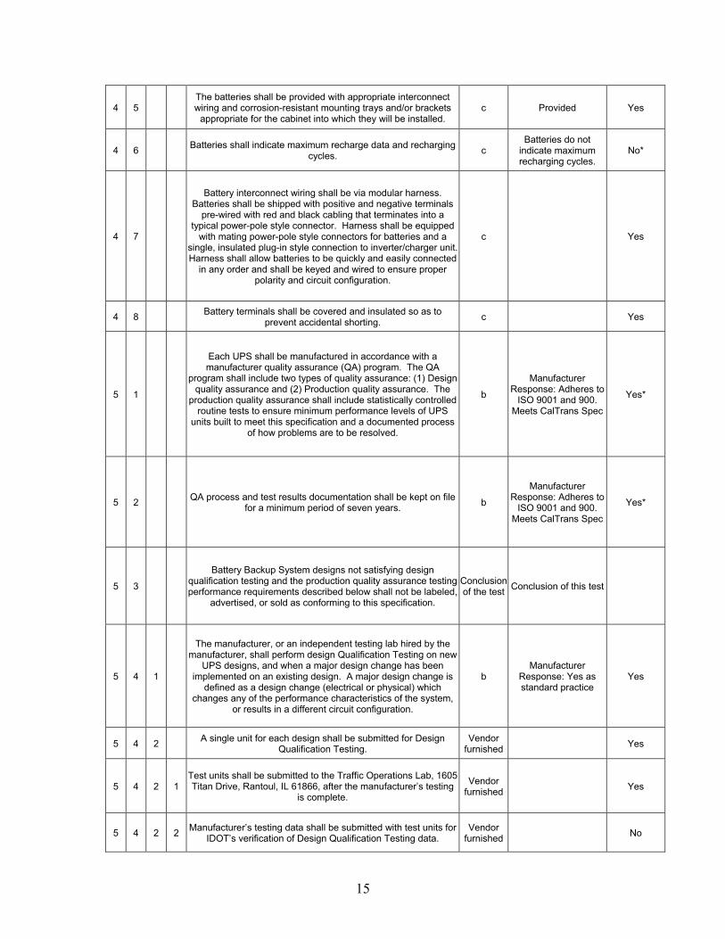
4 5 The batteries shall be provided with appropriate interconnect wiring and corrosion-resistant mounting trays and/or brackets
appropriate for the cabinet into which they will be installed. c Provided Yes
4 6 Batteries shall indicate maximum recharge data and recharging cycles. c
Batteries do not indicate maximum recharging cycles.
No*
4 7
Battery interconnect wiring shall be via modular harness. Batteries shall be shipped with positive and negative terminals
pre-wired with red and black cabling that terminates into a typical power-pole style connector. Harness shall be equipped
with mating power-pole style connectors for batteries and a single, insulated plug-in style connection to inverter/charger unit. Harness shall allow batteries to be quickly and easily connected
in any order and shall be keyed and wired to ensure proper polarity and circuit configuration.
c Yes
4 8 Battery terminals shall be covered and insulated so as to prevent accidental shorting. c Yes
5 1
Each UPS shall be manufactured in accordance with a manufacturer quality assurance (QA) program. The QA
program shall include two types of quality assurance: (1) Design quality assurance and (2) Production quality assurance. The
production quality assurance shall include statistically controlled routine tests to ensure minimum performance levels of UPS
units built to meet this specification and a documented process of how problems are to be resolved.
b
Manufacturer Response: Adheres to
ISO 9001 and 900. Meets CalTrans Spec
Yes*
5 2 QA process and test results documentation shall be kept on file for a minimum period of seven years. b
Manufacturer Response: Adheres to
ISO 9001 and 900. Meets CalTrans Spec
Yes*
5 3
Battery Backup System designs not satisfying design qualification testing and the production quality assurance testing performance requirements described below shall not be labeled,
advertised, or sold as conforming to this specification.
Conclusion of the test Conclusion of this test
5 4 1
The manufacturer, or an independent testing lab hired by the manufacturer, shall perform design Qualification Testing on new
UPS designs, and when a major design change has been implemented on an existing design. A major design change is
defined as a design change (electrical or physical) which changes any of the performance characteristics of the system,
or results in a different circuit configuration.
b Manufacturer
Response: Yes as standard practice
Yes
5 4 2 A single unit for each design shall be submitted for Design Qualification Testing.
Vendor furnished Yes
5 4 2 1 Test units shall be submitted to the Traffic Operations Lab, 1605 Titan Drive, Rantoul, IL 61866, after the manufacturer’s testing
is complete.
Vendor furnished Yes
5 4 2 2 Manufacturer’s testing data shall be submitted with test units for IDOT’s verification of Design Qualification Testing data.
Vendor furnished No

16
5 4 3
The sample systems shall be energized for a minimum of 5 hours, with full load of 700 watts, at temperatures of +74°C and
-37°C (+165oF and –35oF), excluding batteries, before performing any design qualification testing.
b Manufacturer
Response: Yes as standard practice
Yes
5 4 4 Any failure of the UPS, which renders the unit non-compliant with the specification after burn-in, shall be cause for rejection. b
Manufacturer Response: Yes as standard practice
Yes
5 4 5 For Design Qualification Testing, all specifications will be measured including, but not limited to: b
5 4 5 1 Run time while in battery backup mode, at full load. Yes
5 4 5 2 Proper operation of all relay contact closures (“On-Batt”, “Low-Batt”, “Timer” and “UPS-Fail”). Yes
5 4 5 3 Inverter output voltage, frequency, harmonic distortion, and efficiency, when in battery backup mode. Yes
5 4 5 4 All utility mode – battery backup mode transfer voltage levels. See UPS Spec 1.8, 1.11 and 1.12. Yes
5 4 5 5 Power transfer time from loss of utility power to switchover to battery backed inverter power. Yes
5 4 5 6 Backfeed voltage to utility when in battery backup mode. Seeking certification from manufacturer Yes*
5 4 5 7 IEEE/ANSI C.62.41 compliance. Seeking certification from manufacturer Yes*
5 4 5 8 Battery charging time. Verified at room temperature only. Yes
5 4 5 9 Event counter and runtime meter accuracy. Yes
5 5 1
Production Quality Control tests shall consist of all of the above listed tests and shall be performed on each new system prior to shipment. Failure to meet requirements of any of these tests
shall be cause for rejection. The manufacturer shall retain test results for seven years.
b
On each unit, tests corresponding to
5.4.5.3, 5.4.5.5 and 5.4.5.6 are performed. One out of a batch of 300 units is picked
and tests corresponding to
5.4.5.4 and 5.4.5.7 are performed.
No*
5 5 2 Each UPS shall be given a minimum 100-hour burn-in period to catch any premature failures. b Company response:
48 hours No*
5 5 3 Each system shall be visually inspected for any exterior physical damage or assembly anomalies. Any defects shall be cause for
rejection. b
Manufacturer Response: Yes as standard practice
Yes
5 6 1 The IDOT will perform random sample testing on all shipments, consistent with ANSI/ASQC Z1.4-1993 Sampling Procedures
and Tables for Inspection by Attributes. Under
consideration
5 6 2 Sample testing will normally be completed within 90 days after
delivery to the Traffic Operations Laboratory, barring deficiencies in the shipment, which would reset the clock.
Under consideration

17
5 6 3 All parameters of the specification may be tested on the shipment sample. Yes
5 6 4 The number of units tested (sample size) shall be determined by the quantity in the shipment. The sample size and acceptance or rejection of the shipment shall conform to ANSI/ASQC Z1.4.
Under consideration
6 0
Manufacturers shall provide a two (2) year factory-repair warranty for parts and labor on the UPS from date of
acceptance by the State. Batteries shall be warranted for full replacement for two (2) years from date of purchase. The warranty shall be included in the total bid price of the UPS.
a
Warranty on pg. 65 of Manual states that the warranty is valid for 24 months from the date of Manufacture, NOT date of acceptance by
the state. Also for batteries the warranty
is provided by the original manufacturer
and NOT Myers.
Yes*
Related Documents