Report On Final Slurry Wall Design Containment Barrier Wall Installation MIDCO I SITE Gary, Indiana HANSON ENGINEERING P.C. Soils, Foundations & Underground Specialists EPA Region 5 Records Ctr. 216877 Prepared for: CONTRACT DEWATERING, INC, Prepared By: HANSON ENGINEERING, P.C. Project No. 03144-011 November 17, 2003

Welcome message from author
This document is posted to help you gain knowledge. Please leave a comment to let me know what you think about it! Share it to your friends and learn new things together.
Transcript

Report On
Final Slurry Wall DesignContainment BarrierWall Installation
MIDCO I SITE
Gary, Indiana
HANSONENGINEERING P.C.Soils, Foundations & Underground Specialists
EPA Region 5 Records Ctr.
216877
Prepared for:
CONTRACT DEWATERING, INC,
Prepared By:
HANSON ENGINEERING, P.C.
Project No. 03144-011
November 17, 2003
HANSONENGINEERING PC.Safe, Foundation 4 Underground Specialists
November 20, 2003Project Number 03144-011
Mr. Richard NeumannContract Dewatering, Inc.5820 West Riverside DriveP.O. Box 1Saranac, Michigan 48881
Re: Clarification of Slump and Permeability Sampling IntervalsContainment Barrier Wall (CBW) InstallationMidco I Site7400 West Fifteenth AvenueGary, Indiana
Dear Mr. Neumann:
As a followup to our telephone conversations with you and Ms. Cynthia Bonczkiewicz,P.E. of ENVIRON today, this letter will serve to clarify the slump testing and permeabilitysampling required for the referenced project. In our design report we stated that one slump andone permeability sample would be obtained for every 600 cubic yards (every 80 feet) of CBW.The 600 cubic yard interval conforms to Table 3-4 from "Evaluation of Subsurface EngineeredBarriers at Waste Sites" EPA 542-R-98-005 August 1998. The interval along the wall shouldhave stated approximately every 240 feet instead of every 80 feet. The final report that is to besubmitted after all reviews have been completed will indicate the interval to be approximatelyevery 240 feet.
It is hoped this information is sufficient to fulfill your present requirements. Should youhave any questions or require additional information, please do not hesitate to call. We lookforward to working with you on this project.
Very truly yours,HANSON ENGINEERING, P.C.
Barney L. Thomas, P.E. Daniel L. Hanson, P.E.Project Manager Principal Engineer
40595 Koppernick Road o Canton, Ml 48187 o Phone: (734) 454-6560 o Fax:(734)454-7423

HANSONENGINEERING PC.Safe, Foundation & Underground Specialists
November 20, 2003Project Number 03144-011
Mr. Richard NeumannContract Dewatering, Inc.5820 West Riverside DriveP.O. Box 1Saranac, Michigan 48881
Re: Submittal for Road Crossing Design ChangeContainment Barrier Wall (CBW) InstallationMidco I Site7400 West Fifteenth AvenueGary, Indiana
Dear Mr. Neumann:
As a follow-up to our telephone conversations, we are enclosing details for a proposeddesign change at the road crossings. The change involves placing a bentonite Volclay CRbentonite panel over the Shoreguard sheeting interlocks after the sheeting has been installedinstead of solvent welding the sheeting before placing the sheets in the CBW. The Volclay* CRbentonite panels are to be installed on the sheeting side that faces to the outside of the CBW. TheVolclay* CR bentonite panels have been specified since the bentonite used is designed to beused where contaminated groundwater or high levels of salt concentrations are in the water. Byusing the Volclay* CR bentonite panels at the interlocks seepage through the interlock locationswould be small considering the minimal void space at the interlocks as well as the lowpermeability of the Volclay* CR bentonite panels. Technical information regarding the Volclay*CR bentonite panels is included with this letter.
It is hoped this information is sufficient to fulfill your present requirements. Should youhave any questions or require additional information, please do not hesitate to call. We lookforward to working with you on this project.
Very truly yours,HANSON ENGINEERING, P.C. , , _, ,
llBarney L. Thomas, P.E. Daniel L. Hanson, P.E.Project Manager Principal Engineer
40595 Koppernick Road o Canton, Ml 48187 o Phone: (734) 454-6560 O Fax: (734) 454-7423

•5.0'-BLAINE STREET
" WIDTH VARIES•5.0'-
PLACE VOLCLAY®CR BENTONITEPANELS AT EACH SHEETING
INTERLOCK ON OUTSIDEOF CONTAINMENT AREA
(SEE TYPICAL DETAIL)
SOIL-BENTONITESLURRY WALL 5.0'
2.0'
• SHEET PILE CUT OFF WALL,SHOREGARD PVC SHEET PILES, S 300
OUTSIDE CONTAINMENTAREA 5.0'
PLAN VIEWSCALE: 1" = 5'
•PERIMETER OF AGGREGATEBASE AND GEOTEXTILE
ROAD CROSSING DETAILSPAGE 1 OF 3

DENSE GRADED AGGREGATEBASE(INDOTNO. 53)
SEE DETAIL X
MIRAFI MIRAGRID8XT GEOGRID
DENSE GRADED AGGREGATEBASE (INDOT NO. 53)
MIRAFI HP570 WOVENGEOTEXTILE
VOLCLAY*CR BENTONITE PANEL INSTALLEDAT INTERLOCKS ON OUTSIDE OF CONTAINMENTAREA
S 300 SHEET PILE
SOIL-BENTONITESLURRY WALL
SECTION C-CSCALE: 1" = 5'
DENSE GRADED AGGREGATEBASE (INDOT NO. 53)
6"- Aiiiiirfiimiiiimiiiiiiiiiiiiiiiiiiimiiiiiin
MIRAFI MIRAGRID8XT GEOGRID
DENSE GRADED AGGREGATEBASE (INDOT NO. 53)
FLUSH WITHSHEETING,CUT TO FIT
VOLCLAY*CR BENTONITE PANEL INSTALLEDAT INTERLOCKS ON OUTSIDE OF
CONTAINMENT AREA
MIRAFI HP570 WOVENGEOTEXTILE
SHOREGARD S 300 SHEET PILE
SOIL-BENTONITESLURRY WALL
DETAIL XSCALE: NONE
ROAD CROSSING DETAILSPAGE 2 OF 3
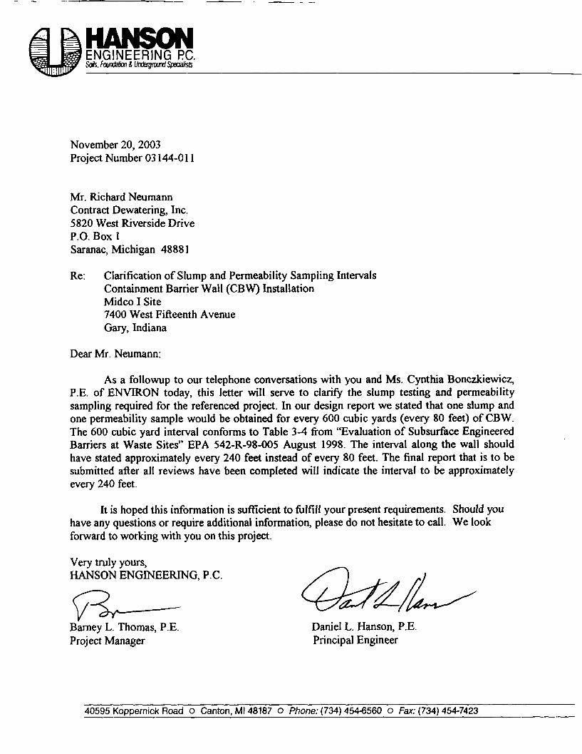
PLACE VOLCLAY®CRBENTONITE PANELS AT
EACH SHEETINGINTERLOCK ON OUTSIDEOF CONTAINMENT AREA SHEET PILE CUT OFF WALL,
SHOREGARD PVC SHEET PILES, S 300
YOUTSIDE OF CONTAINMENT AREA
FINISH ROADSURFACE
VOLCLAY PANEL INSTALLATION DETAILSCALE: 1"=1'
VOLCLAY® CR BENTONITE PANEL,6" WIDE, CENTERED OVER
"SHEETING INTERLOCKS ATOUTSIDE OF CONTAINMENT AREA
^SHEETING INTERLOCKS
p-12"(TYP)-|
- TOP OFSHEETING
24"
- TOP OF SLURRYWALL AT ROADCROSSING
1.0'
SECTION Y-YSCALE: 1" = V
ROAD CROSSING DETAILSPAGE 3 OF 3

VOICLAY PANELSBENTONITE WATERPROOFING SYSTEM
DESCRIPTIONVolclay Panels are a highly effective waterproofingsystem composed of a biodegradable kraft board filledwith high-swelling, sodium bentonite. Volclay Panelscontain a controlled rate of 1 pound per square foot (4.8kg/m2) of Volclay sodium bentonite inside the flutes ofthe 4' x 4' x 3/16' thick (1.2m x 1.2m x 4.7 mm) corru-gated kraft board. A special version, Volclay Type 1-CPanel, features a clear, water-resistant coating on theprint side of the Panel to inhibit premature hydration ofthe bentonite from inclement weather prior to backfill-ing. Once backfilled, Volclay Panels hydrate and form amonolithic waterproofing membrane. Volclay Panelscontain zero VOC, can be installed in almost any weathercondition to green concrete, and most importantly, haveproven effective for more than 35 years.
Volclay Panels work by forming a low permeabilitymembrane upon contact with water. When wetted,unconfirmed bentonite can swell up to 15 times Its dryvolume. When confined under pressure the swell iscontrolled, forming a dense, impervious waterproofingmembrane. The swelling action of Volclay can self-healsmall concrete cracks caused by ground settlement,concrete shrinkage, or seismic action; problems overwhich there is normally no control.
APPLICATIONSVolclay Panels are designed for below-grade structuralconcrete foundation walls. Typical applications includebackfilled concrete foundation and retaining walls.Applications may include structures under continuous orintermittent hydrostatic pressure. Volclay Panels are notdesigned for below-grade masonry block walls.
Where contaminated ground-water or saltwater condi-tions exist, consult CETCO regarding recommendedVolclay waterproofing products and installation guide-lines.
INSTALLATIONGeneral: Install Volclay Panels In strict accordance withthe manufacturer's installation guidelines. Use accessoryproducts as recommended. Install both Type 1 and Type1 -C Panels with the print side facing the installer. InstallWaterstop-RX in all applicable horizontal and verticalconcrete construction joints. Schedule waterproofingmaterial installation to permit prompt placement of com-pactible backfill material. For applications not coveredherein, contact CETCO for specific installation guide-lines.
THE IStAl GflEEN fiRCHITIDTQfiEWfiT£BPR08fWG fflEMBiAHE
DATA
Consisting only of a natural mineral and biodegrad-able kraft board, Volclay Panels are one of the mostenvironmentally friendly waterproofing productsmaking them an ideal choice for green architectureprojects.
Volclay Panel corner cut away shows the corrugationflutes of the biodegradable kraft board are filled withHb/sf of granular sodium bentonite.

Preparatory Work: Concrete surfaces should be free of voidsand sharp projections. Surface irregularities should beremoved before installation. Apply BentoseaP to form-tiepockets, construction joints and honeycombs in con-crete. Tapered form-tie holes extending through the wallshould be completely filled with non-shrink grout.
Panel Installation: Starting at a bottom outside comer of thewall, bend Panel around the corner along the "Starter Line"(printed on Panel) with the kraft board corrugations vertical-ly oriented. Cut the Panel at the bottom along the "StarterLine" so that the Panel can be extended onto the footing aminimum of 6" (150 mm). Secure Panels with washerheadconcrete fasteners along each edge and one or two fastenersin the center. Cut and apply a Panel section at the footing cor-ner base where the Panel does not cover. Then applyBentoseal over the Panel section at the corner. After securingthe corner Panel, install adjacent Panels with corrugations(and print) horizontally oriented. Overlap all adjoiningPanel edges a minimum of 1-1/2" (38 mm) and extend ontofooting a minimum of 6" (150 mm). Continue horizontalplacement until the next corner. At the next corner install thePanel with print vertical. At the inside corners, apply a con-tinuous 3/4" (18 mm) fillet of Bentoseal directly in the cornerprior to installing the Panels.
Place Hydrobar Tubes tight against the Panel along thewall/footing intersection at the bottom of the wall. "Butt"Hydrobar Tube ends together and tamp a shovel of backfillover them immediately to prevent displacement. Replace anydamaged or prehydrated materials prior to backfilling.
Begin the next course at the original outside corner bypositioning the Panel at the corner along the "Alternate Line"(printed on Panel) overlapping the previous course a mini-mum 1-1/2" (38 mm). After securing the corner Panel, installadjacent Panels with kraft board corrugations and printhorizontally oriented. Overlap all adjoining Panel edgesa minimum of 1-1/2" (38 mm). Repeat Panel installationprocedure to finished grade level.
To closely fit around penetrations, cut Panels parallel with thecorrugations. Immediately seal open Panel corrugation edgeby applying a small amount of water with a wet cloth orsponge prior to Panel installation. Trowel a minimum 1/2" (12mm) thick layer of Bentoseal around penetrations. ExtendBentoseal onto penetration and completely fill areabetween Panel edge and penetration.
Terminate Panels at finished grade with a rigid terminationbar fastened 12" (300 mm) on center. Embed top edge ofPanels in 2" (50 mm) wide, by 1/2" (12 mm) thick layer ofBentoseal. A12" (300 mm) wide strip of UV resistant flashingmaterial is also recommended to be installed over the topedge of the Panels at grade.
Backfill material should be compacted to 85% of ModifiedProctor density immediately following the application ofeach Panel course. Backfill to within 3" (75 mm) of the topedge of the Panel. If backfill cannot be applied immediately,protect Type 1 Panels (non-coated) from precipitation withpolyethylene sheeting. Remove sheeting prior to backfilling.If backfill contains sharp or irregular material, cover Panels
with Protection Mat 10V or Aquadrain' drainage compositeto avoid damage during backfilling and compaction.
Tie into underslab waterproofing as required by overlappingthe underslab waterproofing a minimum of 6" (150 mm).When a drain tile is required, install it below the top of thefooting - not in direct contact with the waterproofing.
SIZE AND PACKAGINGVolclay Type 1 and Type 1 -C Panels are 48" x 48' x 3/16'thick (1.2m x 1.2m x 4.7 mm). Each Panel weighs approxi-mately 18 Ibs. (8 kg). Volclay Panels are packaged 125panels per pallet; 2000 sq. ft. (185 sq.m.) per pallet.
Storage: Keep all Volclay materials dry, with adequate poly-ethylene or canvas cover for sides and top. Block up or pal-let materials to prevent contact with ground surface water.
TECHNICAL DATAVolclay sodium bentonite is composed of a minimum of 90%high-swelling montmorillonite.
Permeability Rating. Volclay Panels have been tested byindependent testing laboratories in accordance with ASTM D5084, and have a measured permeability of 1 x 10"9 cm/sec.
Hydrostatic Resistance: A single course of Volclay Panelsis rated to withstand 33' (10 m) of hydrostatic head. Forhydrostatic conditions greater than 33' (10 m), a doublecourse of Volclay Panels is required.
Crack Bridging Ability: Laboratory testing has shown thatVolclay Panels are capable of bridging cracks in concrete upto Vis" (1.5 mm).
Free Swell Rating: 2 grams of sodium bentonite sifted intodeionized water swells a minimum volume of 16 cc.
Bentonite Mass per Unit Area: ASTM D 3776 (mod), 1.0pound per square foot (4.8 kg/mz).
ACCESSORY PRODUCTSVolclay Panel System accessories include:
BENTOSEAL*: patented trowel grade sodium bentonitecompound used as a detailing mastic around penetrationsand corner transitions. Bentoseal is packaged in 3 gallonpails (36 Ibs (16.34 Kg)).
HYDROBAR TUBE1: 2" (50 mm) diameter x 24" (610 mm)long, water soluble casing tube filled with Volclay Bentonite.It is used as a convenient method of adding extra bentoniteat the footing/wall intersection. Hydrobar Tube is packaged32' (9.7 m) per carton.
WATERSTOPPAGE': pure granular Volclay Bentonite usedto detail critical areas that may require extra Volclay protec-tion. Waterstoppage is packaged in 50 Ib. (22.70 Kg) bags.
AQUADRAIN*: prefabricated drainage composite consist-ing of a heavy filter fabric adhered to a high-strength poly-styrene drainage core. Aquadrain is available in 4' x 52' rolls.
PROTECTION MAT 10V: heavy geotexile protectioncourse materials that protect installed Volclay Panels frombackfill damage.
WATERSTOP-RX": expanding bentonite-based concretejoint strip waterstop designed to replace PVC dumbbellwaterstops. Waterstop-RX is manufactured in flexible stripsthat are adhered into place with Volclay WB-Adhesive.Also place Waterstop-RX around applicable penetrations.
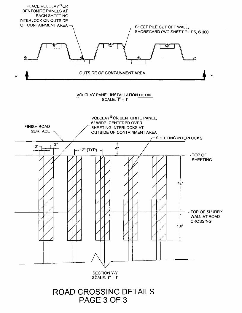
LIMITATIONSDo not install Volclay Panels in standing water or duringprecipitation. If ground water contains strong acids, alkalies,or is of a conductivity of 2,500 umhos or greater, submitwater samples to the manufacturer for compatibility testing. Ifcontaminated ground-water or saltwater conditions exist,consult CETCO regarding recommended Volclay waterproof-ing products and installation guidelines.
Volclay Panels are not designed for unconfirmed above-gradewaterproofing applications or below-grade masonry blockfoundation walls. Do not install Volclay Panels in horizontalsplit-slab plaza deck applications that will receive a pouredconcrete wear surface or other solid topping.
Volclay panels are not designed for below-grade masonryblock foundation walls, with or without a cementituous par-get . Consult CETCO regarding recommended Volclay water-proofing products and installation guidelines.
Volclay Panels are not designed to waterproof expansionjoints. Expansion joints require a properly engineered expan-sion joint sealant product manufactured by other companies.
Backfill should consist of compactible soils, pea gravel, orcrushed stone (3/4" or less). Compact soils to minimum 85%Modified Proctor density. Stone backfill larger than 3/4"(18 mm) may require the use of a protection course; consultCETCO for specific guidelines. Avoid backfill with aggregatelarger than 1-1/2" (38 mm).
USGBC - INDUSTRY PARTNER
CETCO is an Industry Partner of the US Green BuildingCouncil (USGBC). USGBC is a national, committeebased, consensus organization representing a full crosssection of the building industry whose mission is toaccelerate the adoption of green building practices, tech-nologies, policies, and standards through market basedsolutions. USGBC's primary vehicle for promoting sus-tainable design and construction is the LEED RatingSystem (LEED - Leadership in Energy and EnvironmentalDesign). The LEED Rating System has been developed inresponse to the U.S. market's demand for a definition of"green building'.
Volclay Panels, consisting solely of natural sodium ben-tonite carried in a biodegradable kraft board, is one ofthe most environmentally friendly waterproofing materi-als in the world. Containing no volatile organic com-pounds (VOCs) Volclay Panels have been used success-fully on thousands of projects worldwide.
BACKFILLED CONCRETE WALL DETAIL
JUL4 | jl » „ 44v<.-.-.v.44M«M4*.-.v&.-d-
*"*~ --- •*
Trowel Bentosealover patched form-'tie holes
Volclay Panels
Hydrobar Tubes
Concrete wall
Stagger all verticaloverlap seams
1-1/2'(38 mm)overlap
Waterstop-RX(min. 3" coverage)
6'(150 mm)

UOICLAY PANEL WATERPROOFINGGENERAL APPLICATION DETfllLS
NON-HVDROSTATIC CONDITION HVDROSTATIC CONDITION
VoldayPanels
Hydrobar
Tubes
Waterstop-RX
(min 3" coverage)VoldayPanels
Waterstop-RX(min 3' coverage)
VoldayVoltex
WALL PENETRATION DETAIL INSIDE CORNER DETAIL
VoldayPanels"
! Waterstop-RX
{min 3* coverage)
Bentoseal 1 Pipe
Concretewall —
3/4- fillet of' Bentoseal
Bend Volclay Panel to fit corner
TYPICAL GRADE TERMINATION
%*»—\,. Finished Grade
Bentoseal
Metal Termination Barfastened 12" on center
ir wide UV resistantmembrane (optional)
Volday Panels
SEPTEMBER 2002(Supersedes All Previous Versions)
The Information contained herein supersedes all previous versions printedprior to September 2002. and Is believed to be accurate and reliable. CETCOmakes no warranty of any kind and accepts no responsibility for the resultsobtained through application of this Information CETCO reserves the right toupdate information without notice
Building Materials Group1500 West Sue Drive Arfngton Hei tj, I 60004-1440 USAW (847) 392,5800 fax (847) 506.6195 hfy://wwf.Kko.com
(800) 527.9948
C 2002 ChTCO Printed In the US.A Korm: VPTD-3SB 9/02 O Printed on recycled paper
Building Materials Group - Products - Volclay Panels - Product Specifications Page 1 ot 2
C txitmsg Pmdm*»
ProductsAdvantagesBentonite WPAbstractFAQsMap/Contacts
Product Literature
)
[PRODUCT SPECIFICATIONS]
VOLCLAY PANELS PRODUCT SPECIFICATIONSPANEL SPECIFICATIONS
Bentonite Content
Dry Thickness
Panel Width
Panel Height
Typical Panel Weight 18 Ibs. (8.1 kg)
SODIUM BENTONITE
Granular Size
1 Ib./ft2 (4.8 kg/m2)
0.187 inch (4.8mm)
4 feet (1.2m)
4 feet (1.2 m)
Type
90% passing 20 Seive10% passing 200 Seive
90% Montmorillinite10% Unaltered Volcanic Sediment
Free Swell Rating 2 grams swell to 16cc volume in deionized water
PHYSICAL PROPERTIES
Property Test Method Typical Property
Permeability ASTM D 5084 1 x 10'9 cm/sec.
Puncture Resistance ASTM D 781 95 Ibs. (422 N)
http.//www.cetco.com/groupsftmg/volclay/panels_product_specs.asp 11/20/2003
Building Materials Group - Products - Volclay Panels - Product Specifications Page 2 of 2
PACKAGING 125 Panels per pallet.2000 square feet per pallet (185.8 square meters per pallet)
TYPE 1-C (COATED) Type 1-C Panels have a temporary water-resistant coating applied to the print side of thePANELS Panel. The clear coating inhibits premature hydration from inclement weather prior to
backfilling or concrete placement. Once backfilled, the Type 1-C Panel will hydratenormally, forming a seamless waterproofing membrane. Type 1-C Panels (one-side coated)are designed for both vertical and horizontal applications.
AppHcaions | General Specifications | Product Specifications | Accessory Products! Details | Project References
Products I Product Llt«ratur>/T>chnlcal Dttt Sh««t» I Advantad«s I B«ntontt« WP Abstract I FAQs I Map/Contacts
j Visit Other CETCO Divisions :|;; Parent Company and Subsidiaries ;-|:
Copyright 2002 CETCO All rights r»s«rv»d. CETCO I* • wholly own*d subsidiary of AMCOL International Corp. L«q«l T«rm» and Conditions of Us« | PrlvicvPolicy1500 Wsst Shun Driv*. Arlington H«(ght», Illinois 60004 USA | +1.600.527.9948 | tel: 847.392.5800 | fax: +1.847.506.6195
For questions regarding this stt», contact w»bmast»rgc«tco.com
http://www.cetco.com/groups/bmg/volclay/panels_product_specs.asp 11/20/2003
Building Materials - Products - Volclay Page 2 of 3
bentonite activates and stops the water.
Swelttite is easy to install. It can be applied in most weather conditions to freshly poured concrete without a primer oradhesive. Swelttite is manufactured in a controlled thickness to assure the contractor, design professional and owner of aproper waterproofing installation. The products unique composite eliminates the use of a release paper and the toughHOPE liner eliminates the need for a protection course for most installations.
Quality and ease of installation have made Swelltite a market leader. Over 50 million square feet of Swelltite have beeninstalled worldwide on projects such as airports, commercial buildings, transportation tunnels and military facilities.
Applications | General Specifications | Product Specifications | Accessory Products | Details | Project References
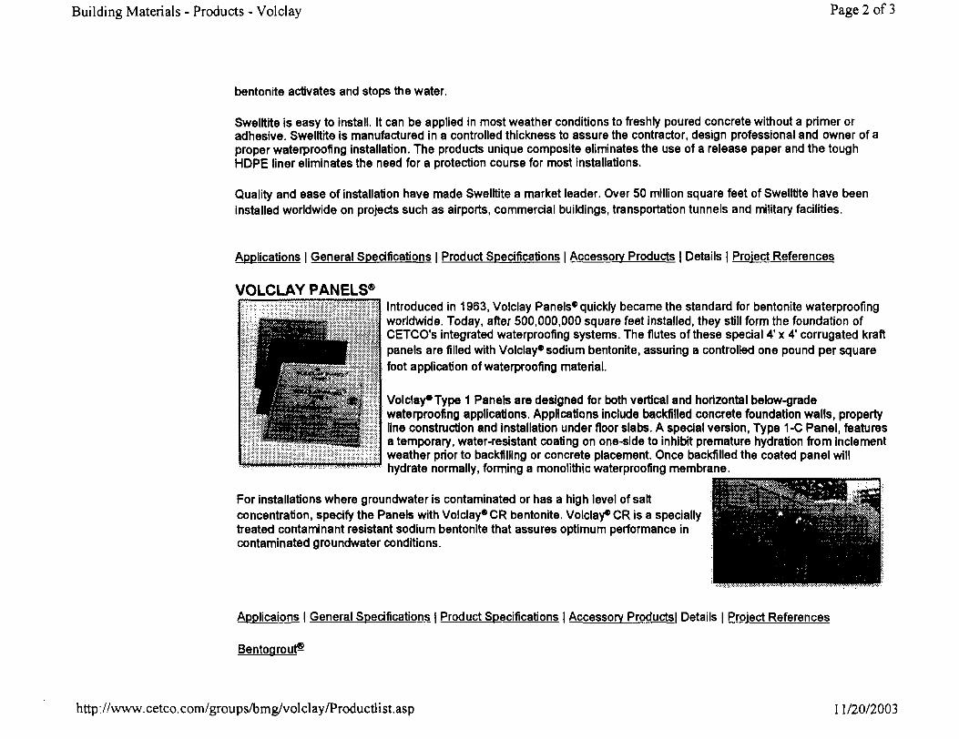
VOLCLAY PANELS®Introduced in 1963, Volclay Panels* quickly became the standard for bentonite waterproofingworldwide. Today, after 500,000,000 square feet installed, they still form the foundation ofCETCO's integrated waterproofing systems. The flutes of these special 4' x 4' corrugated kraftpanels are filled with Volclay* sodium bentonite, assuring a controlled one pound per squarefoot application of waterproofing material.
Volclay* Type 1 Panels are designed for both vertical and horizontal below-gradewaterproofing applications. Applications include backfilled concrete foundation walls, propertyline construction and installation under floor slabs. A special version, Type 1-C Panel, featuresa temporary, water-resistant coating on one-side to inhibit premature hydration from inclementweather prior to backfilling or concrete placement. Once backfilled the coated panel willhydrate normally, forming a monolithic waterproofing membrane.
For installations where groundwater is contaminated or has a high level of saltconcentration, specify the Panels with Volclay* CR bentonite. Volclay* CR is a speciallytreated contaminant resistant sodium bentonite that assures optimum performance incontaminated groundwater conditions.
Applicaions | General Specifications | Product Specifications | Accessory Products! Details | Project References
Bentoarout^
http: //www. cetco. com/groups/bmg/vol cl ay/Productli st.asp 11/20/2003
HANSONENGINEERING PC.Soils, Foundation & Underground Specialists
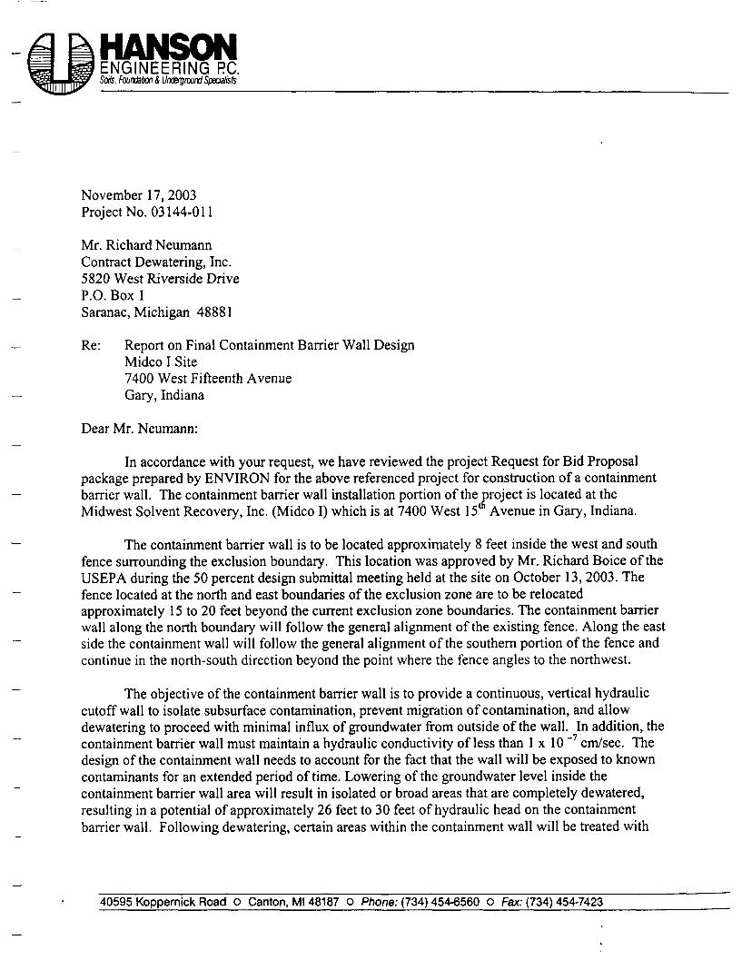
November 17,2003Project No. 03144-011
Mr. Richard NeumannContract Dewatering, Inc.5820 West Riverside DriveP.O. Box 1Saranac, Michigan 48881
Re: Report on Final Containment Barrier Wall DesignMidco I Site7400 West Fifteenth AvenueGary, Indiana
Dear Mr. Neumann:
In accordance with your request, we have reviewed the project Request for Bid Proposalpackage prepared by ENVIRON for the above referenced project for construction of a containmentbarrier wall. The containment barrier wall installation portion of the project is located at theMidwest Solvent Recovery, Inc. (Midco I) which is at 7400 West 15 Avenue in Gary, Indiana.
The containment barrier wall is to be located approximately 8 feet inside the west and southfence surrounding the exclusion boundary. This location was approved by Mr. Richard Bpice of theUSEPA during the 50 percent design submittal meeting held at the site on October 13, 2003. Thefence located at the north and east boundaries of the exclusion zone are to be relocatedapproximately 15 to 20 feet beyond the current exclusion zone boundaries. The containment barrierwall along the north boundary will follow the general alignment of the existing fence. Along the eastside the containment wall will follow the general alignment of the southern portion of the fence andcontinue in the north-south direction beyond the point where the fence angles to the northwest.
The objective of the containment barrier wall is to provide a continuous, vertical hydrauliccutoff wall to isolate subsurface contamination, prevent migration of contamination, and allowdewatering to proceed with minimal influx of groundwater from outside of the wall. In addition, thecontainment barrier wall must maintain a hydraulic conductivity of less than 1 x 10 ~7 cm/sec. Thedesign of the containment wall needs to account for the fact that the wall will be exposed to knowncontaminants for an extended period of time. Lowering of the groundwater level inside thecontainment barrier wall area will result in isolated or broad areas that are completely dewatered,resulting in a potential of approximately 26 feet to 30 feet of hydraulic head on the containmentbarrier wall. Following dewatering, certain areas within the containment wall will be treated with
40595 Koppernick Road o Canton, Ml 48187 O Phone: (734) 454-6560 o Fax: (734) 454-7423

Mr. Richard NeumannProject No. 03144-011November 17, 2003Page 2
soil vapor extraction. The containment barrier wall is to be designed for a minimum period of 30years.
Site Geologic Conditions
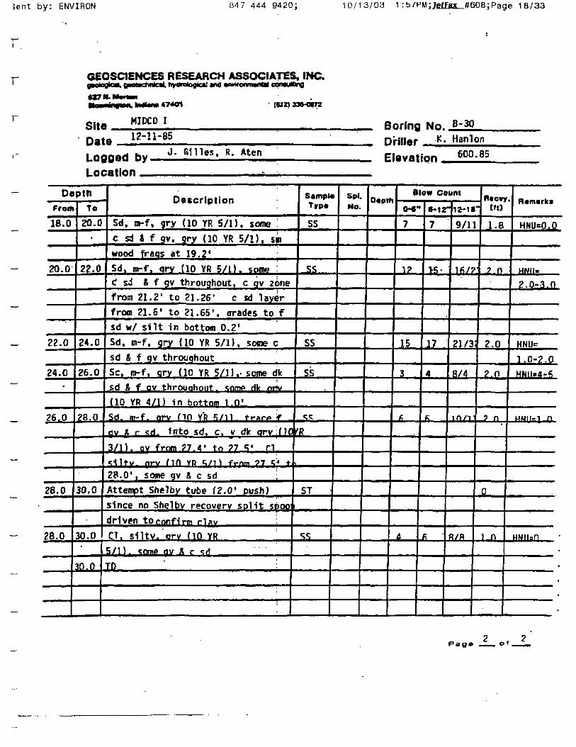
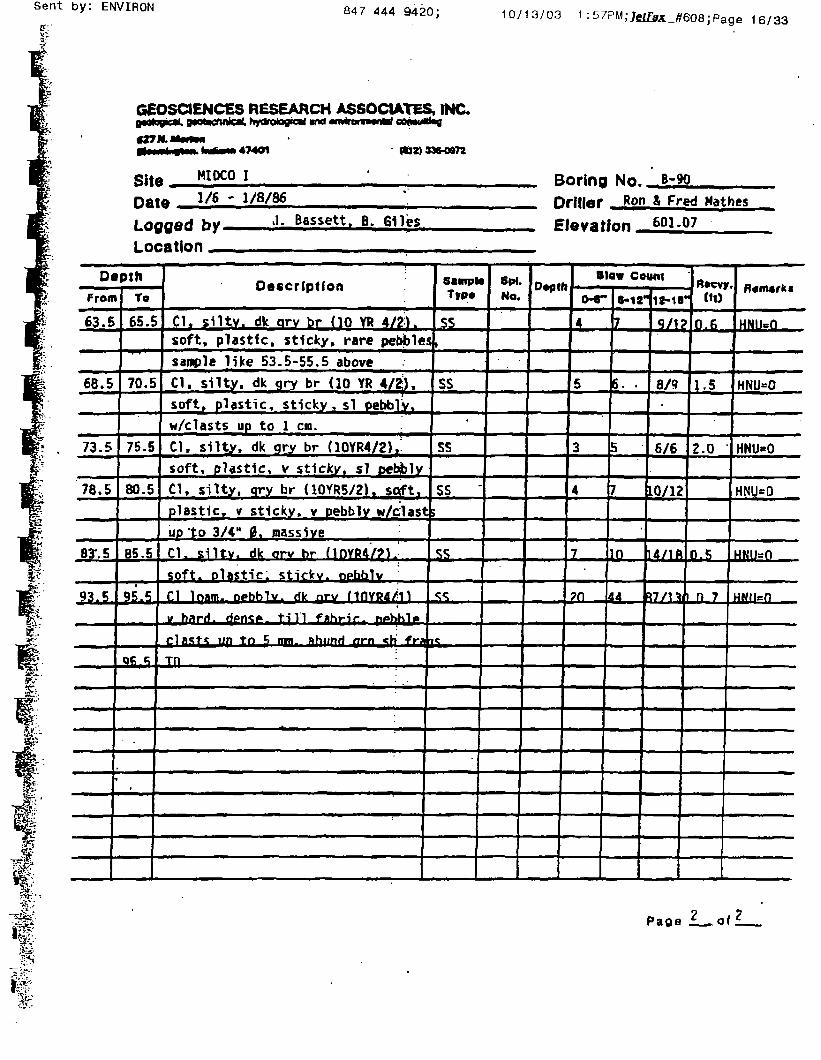
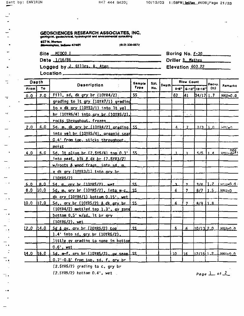
Based on the data presented in the "Health and Safety Plan (HASP) for RemedialDesign/Remedial Action, Midco I and II Sites; Gary, Indiana" prepared by Environmental ResourcesManagement (ERM) - North Central, Inc. and dated May 14, 1993, the site geology is relativelyuniform. Additional subsurface information in the form of boring records was provided byENVIRON. The boring locations are either within the confines of the proposed containment barrierwall or within approximately 100 feet of the containment barrier wall. Four borings (B-30, B-90, C-30, and F-30) were completed at this site in 1985 by Geosciences Research Associates, Inc. In 1993Environmental Resources Management - North Central, Inc. completed seven borings (SB-2, SB-3,SB-4, SB-5, SB-8, SB-P, and SB-R) within or near the alignment of the containment barrier wall.Geosciences also completed one boring (E-200) in 1985 at a location approximately 1000 feet northof the exclusion zone. This boring indicates the presence of the confining layer to a depth ofapproximately 140 feet (EL 470). Additionally, four borings (CDB-1 through CDB-4) werecompleted by Contract Dewatering Services on October 1, 2003 along the alignment of thecontainment wall. All of the boring logs previously mentioned are included in Appendix A.
Based upon elevation data provided by ENVIRON, the ground surface elevation in thevicinity of the containment barrier wall alignment ranges from approximately Elevation 598.7 to603.7. Elevations are NGVD Datum.
The soil profiles presented in the soil boring logs indicate that the upper 25 to 29 feet (toapproximate EL 572 to 575) generally consists of fine to medium sands with occasional pockets ofsand and gravel. Along the south eastern portion of the containment area, 4 to 6 feet of fill was notedabove the sand. The fill consisted of sand, slag, wood and other miscellaneous debris. The sandsmakeup the uppermost aquifer of the region described as the Calumet Aquifer. The hydraulicconductivities calculated from slug tests performed in the monitoring wells located within theCalumet Aquifer at the Midco I site ranged from 1.9 x 10"4 to 7.5 x 10"3 cm/sec. Underlying thesands at the site is silty clay that extends to the termination depth of boring B-90 at 95 feet(approximate EL 505.7) and to approximately EL 470 in a boring (E-200) that is locatedapproximately 1000 feet north of the Midco I site. Hydraulic conductivity tests were performed onsamples of the silty clay layer (key material) with the results indicating that the silty clay depositexhibited a permeability ranging from 8.5 x 10 to 1.0 x 10 cm/sec.
Mr. Richard NeumannProject No. 03144-011November 17, 2003Page 3
Contaminant Concentrations in Ground water
Included in the ERM-HASP was Table 1-3 "Range of Concentrations of CompoundsDetected In Soils, Sediment, Groundwater, and Surface Water During the Remedial InvestigationMidco I Site". For completeness, we have included a copy of this table in Appendix B.
Containment Barrier Wall (CBW) Design
The objective of the containment barrier wall (CBW) is to provide a continuous, vertical,hydraulic cutoff to isolate subsurface contamination, prevent migration of contamination, and allowdewatering to proceed with minimal influx of groundwater from outside of the wall. Thecontainment wall must extend from the ground surface into the underlying silty clay stratum (keymaterial) encountered below approximately Elevation 572 to 575. The CBW must have a hydraulicconductivity of less than 1 x 1 0 ~7 cm/sec and a design life of 30 years. The maximum potentialhydraulic gradient that may exist across the wall is 30 feet.
Contract Dewatering Services, Inc. has proposed to construct a mixed in place soil-bentonitewall constructed using a one pass trencher. The proposal is to place dry bentonite into a shallow pre-trench and then mix the bentonite with the existing soils utilizing a 24 inch diameter wide trencher.Potable water from a nearby fire hydrant will be mixed with the soil and dry bentonite to achieve auniform mix with a slump in the range of 4 to 8 inches.
Due to the relatively high concentrations of chloride along the west wall as a result of the saltstorage at the adjacent INDOT service yard, the bentonite that will be used in the soil-bentonite ofthe north, south, and west legs of the CBW will be Wyo-Ben SW-101. This bentonite is designedspecifically for use where it is exposed to seawater and salt contaminated environments. For the eastleg of the CBW, the bentonite used will be Hydrogel. Along the east leg the chloride concentrationsare less than 4,000 ppm. The manufacturer of the Hydrogel has indicated that this product will not beimpacted by this level of chloride concentration. Product information sheets for these bentonitematerials are included in Appendix C.
The criteria for the evaluation of a containment barrier wall design against acceptableindustry practices are presented in Appendix D of this design report. This criterion is established inTable 3-2 from the EPA publication "Evaluation of Subsurface Engineered Barriers at Waste Sites"(EPA 542-R-98-005 August 1998). :

Mr. Richard NeumannProject No. 03144-011November 17,2003Page 4
Sample Collection and Testing Program for CBW
On October 1, 2003, four auger borings (CDB-1 to CDB-4) were made by ContractDewatering Services, Inc. (CDS) along the proposed CBW alignment. The alignment of the CBW isgenerally located along the current fence alignment line surrounding the exclusion zone with theexception of the northeast portion of the wall where the wall will continue so that the CBW willsquare off at the northeast corner (reference Drawing 03144-011-A). The borings were taken toverify the depth to the surface of the underlying silty clay stratum (key material) and to obtainsamples of the sand overlying the silty clay for testing purposes. A composite sample of the sandsfrom the north, south, and west legs of the CBW was obtained for mixing with the SW-101bentonite. A separate sample was obtained from the east leg for mixing with the Hydrogel bentonite.A sample of the groundwater was obtained on October 8, 2003 from MW-6D and EW-3 for use asthe permeant in the soil-bentonite laboratory permeability and compatibility testing. The sampleswere transported to the offices of Weaver Boos & Gordon LLC for determining the soil-bentonitepermeability using the groundwater samples obtained.
The purpose of the laboratory testing is to essentially verify the design previously utilized byCDS at a site located approximately 5 miles south-southeast of the Midco I site where the soil profileabove the key-in layer consisted of sands similar to those at Midco I. For the Midco I CBW, twosoil-bentonite mixes were made using 4% bentonite by weight of soil. The dry unit weight of the onsite sand has been assumed to be 100 pounds per cubic foot (pcf)- The laboratory permeabilitytesting began the week of October 9, 2003 and has been continuously ongoing since. Thepermeability tests are being performed utilizing a falling-head permeameter in accordance with EPAMethod 9100, Section 2.6. The purpose of the testing program is to determine the hydraulicconductivity of the 4% soil-bentonite mix using the groundwater samples obtained from the site asthe test permeant. At the writing of this report, the testing of the samples with groundwater from thesite is on-going and the results of the laboratory permeability testing are as follows:
Bentonite Type
Hydrogel
SW-101
Soil Source
EWallCombined N, S,and W Walls
Permeant Source
EW-3
MW-6D
HydraulicConductivity, k2o«1.1 x 10 '8 cm/sec
5.5x 10~9 cm/sec
The final results of the testing program will be presented in a supplemental letter as soon asthey become available. The initial test results for the permeability testing are included in AppendixE.

Mr. Richard NeumannProject No. 03144-011November 17,2003Page5
It should be noted that only two samples were tested as part of the design phase. The primarypurpose of the testing is to verify a mix design previously used in the same geologic formation. Itshould also be noted that the site is quite small, and the soil conditions at this site are uniform.Additionally, 20 permeability tests will be completed of the mixed in-place soil-bentonite since asample will be obtained for every 600 cubic yards (80 feet) of constructed wall. Therefore, there willbe a total of 22 permeability tests completed for this wall and no additional design stage testing isrequired.
Based on the data developed to date, the amount of dry bentonite to be placed into the twofoot wide trench should be equal to 8 pounds per foot of trench depth. The bentonite used will bemeasured weight of dry material placed into the pre-trench. The soil-bentonite will be mixed withthe trencher to achieve a uniform mixture with a slump in the range of 4 to 8 inches.
CBW Location
Figure 5-1 - Work Zones Midco I prepared by ERM (dated 11-4-92), included as AppendixF shows the Midco 1 exclusion zone. The project plans require that the CBW be located so that theentire exclusion zone is surrounded. At the west side of the property the exclusion zone is indicatedas along the fence line adjacent to the Indiana Department of Transportation (INDOT) facility. Dueto the presence of overhead utility lines adjacent to the INDOT side of the fence, the CBW cannot beinstalled at the fence line without relocating the utility lines. During the 50 percent design meetingheld at the site on October 20,2003, the representative from the USEPA Region indicated that itwould be acceptable to place the CBW as close to the fence as practical (approximately 8 feet). Thedesign location of the CBW is indicated on Hanson Engineering Drawing No. 03144-011-A. Adetailed site plan with the actual location of the CBW will be submitted with the "As Built"information at the completion of the project.
CBW Hydraulic Considerations
The CBW will be extended 5 feet into the silty clay stratum (key material), which underliesthe site at approximately elevation 572 to 575. The CBW will be 24 inches in width. The depth tothe bottom of the trench will be checked once the trencher has passed. The wall will consist of a soil-bentonite mix with a demonstrated hydraulic conductivity of less than 1 x 10 ~7 cm/sec. Thehydraulic conductivity of the native medium sands is estimated to be in the range of 1.9 x 10 ~*cm/sec to 7.5 x 10 ~3 cm/sec based upon slug tests performed at the site and reported in the ERM-HASP. Thus, the soil - bentonite wall will be at least 1900 times less permeable than the native soils.Thus, the 2 foot wide barrier wall extending 5 feet into the underlying silty clay key material has anequivalent thickness of at least 3800 feet of native sands, based on the ratio of the hydraulicconductivity values alone. As long as the CBW is continuously supported by soil on both sides,lowering the water level 30 feet across the wall will have no significant effect on the CBW.

Mr. Richard NeumannProject No. 03144-011November 17,2003Page 6
CBW Construction Considerations
As previously stated the construction of the CBW will be by the one pass trencher method.The method of construction is discussed in the CDS Work Plan. A copy of the CDS Work Plan hasbeen included herewith as Appendix G. A copy of the CDS Construction Quality Control (CQC)Plan is also included in Appendix G. As with the barrier wall design, the USEPA has developedcriteria for the evaluation of a barrier CQA/CQC against acceptable industry practices. This criterionis established in Table 3-4 from the EPA publication "Evaluation of Subsurface Engineered Barriersat Waste Sites" (EPA 542-R-98-005 August 1998). The content of Table 3-4 along with the level ofeffort for the various CQC categories provided at the Midco I site are included in Appendix H.
If during the excavation of the pretrench unsuitable material such as obstructions ormiscellaneous rubble are encountered, the material will be removed from the area and stockpiled onsite. The depth of excavation will be limited and extend only to or slightly below the existing watertable. The material stockpiled will be managed by ENVIRON.
The actual construction of the CBW will consist of excavating the pretrench and placing drybentonite into the pretrench. The trencher will be lowered to the desired depth and hydrant water willbe added to the trench and mixing of the bentonite with the supplied water and soils will begin. As aresult of this process there will be no fugitive dust that will be created as a result of the trenchingoperations since the soils will be constantly wet.
The means and methods for daily clean up, area restoration, handling of waste, debris and/orfill materials encountered along the alignment are presented in these plans, together with thesequencing of the work. We are unaware of any special utility or access arrangements which will berequired other than the locations where the lines for extraction wells EW-3 and EW-5 will cross theCBW. The approximate location of these lines is indicated on Hanson Engineering Drawing No.03144-011-A.
CBW Construction Personnel
The specifications require that the design report include the resume of key personnelassigned to this project. This information was previously submitted and will not be reproduced here.
Contractor Health and Safety Plan '•t
The CDS Contractor Health and Safety Plan have been included herewith as Appendix I.

Mr. Richard NeumannProject No. 03144-011November 17, 2003Page?
Special Construction Details
Special consideration will be given to the means and methods required to seal subsurfaceutility penetrations through the area where the CBW is to be constructed. This includes areas wherethe extraction well lines pass through the CBW alignment. The procedure is to temporarily cut andcap existing utility piping on either side of the CBW alignment prior to reaching them with thetrencher. After the trencher has passed the utility will be re-connected. The method that will be usedto reconnect the HDPE lines will be to use an electrofusion coupling. The manufacturers'specification sheet for electrofusion couplings is included in Appendix J. Air line piping will bereconnected utilizing a mechanical coupler and then the line will be wrapped with HDPE tape.
We understand that the extraction well line EW-5 has been constructed in a berm which isapproximately 4 feet above the surrounding ground surface. The extraction well lines are located atthe approximate elevation as the surrounding ground surface outside the berm. For EW-3 the linesare not constructed in a berm. At EW-5 the berm will be reestablished by backfilling with soil thatwas excavated from the berm area prior to constructing the CBW and the berm restored. A detail forthe construction sequence at this type of crossing is included in Appendix J and is also indicated onHanson Engineering Drawing No. 03144-011-D. At EW-5 the grade will be reestablished bybackfilling the excavation with a soil-bentonite slurry to within 1-foot of the surface and thenplacing the clay cap in the same manner as the rest of the wall. A detail for the constructionsequence at this type of crossing is included in Appendix J and is also indicated on HansonEngineering Drawing No. 03144-011 -D.
Another special consideration is installation of cover over the CBW at all locations includingthe areas where Elaine Street will cross. At all areas except where Blaine Street crosses, the CBWwill be capped with a 12-inch thick by 30-inch wide cap constructed of a clayey materials that willbe capable of supporting pedestrian traffic. The detail of this section is included in Appendix J and isalso included on Hanson Engineering Drawing No. 03144-011-C.
'.i
At the road crossings Shoreguard S300 PVC sheetpiles will be placed in the CBW andextend to within 6-inches of the ground surface in order to prevent the flow of groundwater fromoutside the CBW into the containment area. The sheeting interlocks will be solvent welded for theentire length of the sheeting. Once the sheeting is placed, a Mirafi HP570 Woven Geotextile will beplaced at the top of the CBW 30-inches below grade and extend 5 feet beyond the edges of the roadand the CBW. Above the geotextile material, INDOT No. 53 will be placed and compacted to form a6 inch layer. A layer of Mirafi Miragrid 8XT Geogrid will then be placed and the remaining densegraded aggregate, meeting the INDOT No. 53 specification, will be placed over the geogrid in 6-inchlifts and compacted to 100 percent of the AASHTO T-99 maximum density. The detail of thissection is included in Appendix J and is also included on Hanson Engineering Drawing No. 03144-011-D.

Mr. Richard NeumannProject No. 03144-011 •:November 17, 2003Page 8 j
:'At the northeast corner of the CBW the existing ground surface is lower than most of the
remaining site. At this location we have included a 1-foot berm to raise the existing grades andprovide a working platform for the trenching equipment. The detail of this section is included inAppendix J and is also included on Hanson Engineering Drawing No. 03144-011-C.
Containment Barrier Wall Specifications
Specifications for the construction of the CBW have been prepared and are presentedherewith as Appendix K.
This report and the CBW mix design have been prepared under the direction of this writer,who is a Licensed Professional Engineer in the State of Indiana. The CBW thickness and depth ofpenetration into the silty clay deposits underlying the site have been determined by this writer. TheCBW alignment and termination locations have been determined based on information provided byothers. If the CBW is constructed as outlined in the text of this report, it is my conclusion that theCBW will meet the objectives indicated.
It is hoped that this information is sufficient to fulfill your present requirements. Should youhave any questions or require additional information, please do not hesitate to call.
Respectfully submitted,HANSON ENGINEERING, P.C.
Barney L. Thomas, P.E.Project Manager
Daniel L. Hanson, P.E.Principal Engineer

a.K*

Sent by: ENVIRON 847 444 9420; 10/13/03 1 :57PM; ;eifM_#608; Page 17/33
GEOSCIENCES RESEARCH ASSOCIATES. INC.u«ot«cl»nic*. hydratoofe*! md wHironflMniri oonwMoo
HIDCO I
• 12-11-85
Boring No. B-3Q
Logged try J-Location
- *•
Driller K. Hanlon
Elevation 60Q-85
DepthFrom
0.0
7.11
4.0
6.0
R n
10.0
12. 0
L4j_P
16 0
To
2.0
4.0
6.0 ,
8.0
in n
'12. ol
14. OJ
t
16 0rl<
ip.o
Fill. Sd, n. oale br (10 YR 6/3) :tolyel br (10 YR 5/4), top 0.5' abund
[root :Fill. sd. m. yel br (10 YR 5/4) too0-2'. dk vel br (10 YR 3/4) 0.2' to
0.81. br (10 VP 5/3), water at 3-fl1
Fill, slag, dk orv br (10 Yft 4/2)
too 0.3', sd, n, v dk orv br
(10 YR 3/2), organic. 0.3' to 0.5',
Sd. m. br (10 YR 5/3) wet
Sd. m. orv br (10 YR 5/2), somethin grv flfl YR «|/1 ) Ixm in hnttrim
n.fi-«?rt ifl pry hp Mn VP *>t?^ CH P
u HI- nry hr flfl YD /7^ fy"ni^ Q a>
to 9.9'
Sd. m-f, ory br (10 YP 5/2i
Sd. m.- ory br (10 YR 5/2) to 13.3'.Sd. m-c. dk orv br (10 YR 4/?l
From 13.3' to 14.0'. some ov :
Sd. m. dk orv br fin YR 4/?K <nmo
f ar w/ some v dk orv br dp yR
3/21 lam :
Sd, m-f. orv br (10 YR 5/?K samp
F QV w/ some dk orv br (10 YR 4/2)
lam
SimpUTypt
SS
SS
SS
SS
«:<:
SS
SS
SS
SS
SpUNo.
.
Depth
..
Blow Count
0-6"
2
3
| s
3
(
6
8
H
35
6-1Z"
1
6 .
7
-i~_
t;
...10
16
IS
12-1i*
0/1
11/1
5/6
i/8
in/1
15/2
J5/23
1R/74
52/92
(tl)
1.1
1.7
2.0
2 0
• ? r^
2.0
1.8
1 n
?.0
R«fnark*
HNU=
sl negdeflHNU=60-7
HNU«
1.0-2.0
HNU-8 0
UNII—
3.0-5.0
HNU=
3.0-4.0
HNU=
?. 0-3.0
MNII-
sl nea
HNU-
sl nea
Page
3ent by: ENVIRON 847 444 9420; 10/13/03 1 :b/PM;jfitfM_#608;Page 18/33
r
r
GEOSC1ENCES RESEARCH ASSOCIATES, INC." ' ' '
W7N.I-•MA. IMfeM 47401 (UZ) 330*0072
MIDCO ISite.DateLogged by.Location _
12-11-85Boring No. B"30
Driller K. HanlonJ. 61 lies, R. Aten
Elevation 600-85
DepthFrom
18.0
20.0
22.0
24.0•
26.0
28.0
28.0
To
20.0•
22-0
24.0
26.0
28.0
30,0
30.0•
0.0
Dfificrlnti-nn
Sd, m-f, gry (10 YR S/l). some '.
c sd 4 f gv. gry (10 YR 5/1), sm
wood fraqs at 19. 2'
Sd. m-f. arv (10 YR 5/L). some :
£ sJ & f gv throughout, c qv zone
from 21.2' to 21.26' c sd layer
from 21.6' to 21.65'. orades to f
sd w/ silt in bottom 0.2'
Sd. m-f. gry (10 YR 5/1), some c
sd & f jjv throughout
Sc. m-f, gry (10 YR 5/1).- some dkSd & f av throuahout , some dk prv
(10 YR 4/1) in bottom l.n«
Sd. m-f. rv fin YR *5/11 trarp <f
ISamptaTrp«
SS
ss
SS
SS
«;<;
tfv * r sd. fnto sd, c, v dk orv :f IQrR
3/1). av from ?7 d1 to ?7 S1 f1
«;ilty firv MO YR /^j fr/"Tl 97 '•^ *f28.0', some gv & c sd ; 1
Attempt Shelby tube (2.0* push) 1 ST
since no Shelbv recovery sol it SDOO
dHvM tO confirm rlay :
Cl. siltv. arv (10 YR
5/1). «0m«- av X r <^fj
TD ' :
«;«;
Spl.No.
D«pttBlow Count
o-e-7
J2_
15
3 I
j;.
A
6*12
7
}5j
17
j I
K
j;
"12-18
9/11
Ifi/?
21/3
8/4
in /v
fl/A
(ft)
1.8
_2 0
2.0
,0
_? n'
0
i n
• Remarks
HNUcO.O
HNII=
2.0-3.0
HNU=
1.0-2.0
HNIIsd-f
UU|f-l (1
HNii=r|,
.
.
.
•
Pag* of

Sent by: ENVIRON 847 444 9420; 10/13/03 1:56PM;/fit&i_#608;Page 15/33
GeOSCIENCES RESEARCH ASSOCIATES, INC.d *nin>m*i*l ccrmM*Q
(U2) M6-08T2•27 N.
14*401
MIDCO I
12-17-85, 1-6-85Site.DateLogged Hy B. Giles. J. Bassett
Location
Boring No, B-90Driller 'R- HathesElevation.
DtpthProm
0.0
. . ,-'
30,0
32.0
35.0
39.5
44.5
48.5
53.5
*>fi 5
To
29.0•
••
32.0
34.0
37 J)
41 .B
4fi.fi
50.5
55.5
fifU
; wccripiiun
Drove 6" steel casing to 29.0' :on12/14 and 12/16/85Drove 4" steel casino to 30.0' on12/17/85See B-30 for boHno loo
Took Shelby tube, allowed to swellfor-jSnrirK No rpcovwvCl. SlltV. orv MO YR S/ll.
2- oebble
C]. «iltv. ^v Mn YR C/1\ cnn»
sm Irregular pebble fragsCl, stlty, orv (10 YR 5/1). sowsm irregular fraos, some sdCK siltv. orv (10 YR S/n. «nIrregular fraas. some sdCl. Siltv. orv far no YR 5/?K
stickv. ola«tic. rare nebble?
Cl. SlltV. dk orv br (7p YR 4/?L
^tifkv nlaqtir rarp nehh1»< mrt<:t
nf*n ^ h
n IrMim nphhlv A\/ nrv Kt« /ID VP
4/2), v firm (good loan till).somewhat brittle ' :
8«nptaTrp«
ST
*T
c<:
SS
'SSI
«y
^<;
SPLNo,
D«DtBlow Gaunt
0-«"
?
3
J .
4
4
45
«-ir
. -
?
,.<
3
5
7
?"*
12-18
.37?
.4/6
4/5
£/£..
vi n
47/r;
R*evy(tl)
.0.0
1 R
1 7
^,9-
Lfi.
7.il
-1..1-
1 2
R«m«rkc
HKii.n
HNII=n
HNU=0
HHII=n _
HNii=n
HNf/=n
HNUeO
Page J ol_L
Sent by: ENVIRON 847 444 9420; 10/13/03 1:57PM;Jetffli_#608;Page 16/33
GEOSC1ENCES RESEARCH ASSOCIATES, INC.
T •1i.11
Sit<OatLo<Lo<
H| Depth
~Ti From
jfc 63.5i.i •
?6B.5
•
, 73.5
W 78'5
HS
JPPp 83*. 5
P
lf;' q3^%-
&
(Kg;SV
B:.
^>"
ffe-E
-pt'fe
g>
If1
TQ
65.5
70.5
75.5
80.5
85.5
95.5
Q6 5
,
9 MIOCO I
OW972
B
,» 1/6 - 1/8/86 ' n
3tjftrt hy >L Bassett. B. Giles p
Oescrl tlonp
Cl. siltv. dk arv br (10 YR 4/2K
soft, plastic, sticky, rare pebble!sample like 53.5-55.5 aboveCl. silty. dk gry br (10 YR 4/2:),
soft, plastic, sticky, si pebbly.w/clasts up to 1 cm.Cl, silty. dk gry br (10YR4/2),:soft, plastic, v sticky, si oebjblyCl, silty, gry br (10YR5/2). soft.
plastic, v sticky, v pebbly w/clast
ScinpH
SS
i,
ss
•
ss
ssJ
up 'to 3/4" 0, massive 1
Cl. siltv. dk orv br (10YR4/9K
soft, olasticl stickv. npbbjy
Cl loam. nPhhlv. rik nrv finve4/H
v hflrH. <it>n<* till fnh»"ir. p^hhl.
cl ast? un to ^ mm. nhunH grp ^f» f r^
rn •
SS
^
Spl.No.
0«pt«
oringfillerlevat
No.Ron
B-90
& Fred Hathes
ion 601.07
Blow Count ^o ..
*-r \ 6-12
4
5
3
7
6. .
5
4 I7
1 •7
j»n
IP
_ 9/l?]0^6
1
8/9
6/6
10/12
1471ft
44 R7/11r
1.5
2.0 '
p. 5
i n 7
,.«.«.HNii=n
HNU=0
HNU=0
HNU=0
HNii=n
HNIleO
* Paoel_ofl__
1

Sent by: ENVIRON 847 444 9420; 10/13/03 1 :57PM; JfitfM_#608; Page 19/33
!HSsf!!S£EiRE^E^?CH ASSOC1ATES'INC-•Z7M.MMM
• (SJ2) 336-0972
Site
474O1
MIOCO I
10/18/85Boring No c~30Driller K- Schwartzkopf
Logged by.Location
J. Bassett, B. Giles Elevation 6DU91
DepthFrom
0.0^ • V^xi*
?.o
4.0
6.0^^^w^^— •
8.0
10.0
12.0-
14.0
16.0
To
2.0
4,o
6.0
8.0
10.0
12J)
14.0
16.0
18.0
Description
Sd. f-m, yel br (10YR 5/8), huraic
in upper 0.3', dry. loose, numerous
rootletsSd. f-m. vel br (10YR 5/8) in uooer
0.4' orftriinp flown to vel br (10YR5/4). moist at top, wet at bas6. lotSd. f-m, gry br (10YR 5/2), mottled
w/br in upper part, wet, runningSd, f-m, yel br {10YR 5/4) in upper
0.8', v dk gry (10YR 3/1) in lower
1.2'Sd. f-m. v dk qry (10YR 3/1). trace
organic lam
Sd. f-n. dk orv (10YR 4/1). c Sd lai
in lower 0.5', rareSd, dk gry (10YR 4/1), wet, soft,thin organic lam at 0.5' from base
Sd. f-m. v dk gry (10YR 3/1),organic lam 0.4' from base includin
spruce? needles & whole plant :frags
Sd. f-ra. v dk orv (10YR 3/1). wet.firm, sham contact at 17.2* to sd.r w/f ov tt 9ran.i|lf*- rnundfid. 17.2-
17.8'. sd. f. v Hk orv. siltv.
nmninn, 17 fl-IR fV
S»mpKTyp«
SS
SS
se to sSS
SS
SS
SS
SS
SS
SS
SpUNo.
)ft
D«pthBlow Count
0-6"
1
4
1
2
4
2
8
12
19
6-12'
2
4- -
2
4
6
2
12
16
20
18-18'
2/2
6/6
3/6
4/6
7/9
8/10
16/1!
20/22
24/3C
R6cvy/••iiMJ
1.7
2.0
1-0
2.0
1.3
2.0
1.9
2.0
2.0
Remarks
HNIMI.1
HNU=neg
defl.
HNU=0
si odor
HNU-neg
si odor,
sewage?
KNU=neg
si odor
sewage
HNU=negsl sewagtod**T*
HfiU=1.4^bwdy
odorHNU=7ppr
petro o
HKU-10-
ppm
petro c
Page J_o« _L

Sent by: ENVIRON 847 444 9420; 10/13/03 1:57PM;Jfit£ai_#608;Page 20/33
rTi
QEOSCIENCES RESEARCH ASSOCIATES, INC.
•Z7N.«MrtM»•liiu«PHI»n lr f i -""" <U2) 336-0972
Rita HIDCO 1
nat« 10/18/85
LoflQftfi hy J- Basset« B- G11es 'f oration
Boring No. C-30
Drillnr K. Schwart2kopf
. PlavHtion 601.91
DepthFrom
18.0
20.0
22.0
24.0
26.0
2B.O
To
20.0
22.0
24.0
26.0
28.0
30.0
30.0
Description
Sd, m w/trace c sd. sllty In upper
0.3', nonqranular. wet. firmSd. f-m. v dk qry (10YR 3/1), :
sugary, rare pebbles A Granules, sd
seam w/mo Husk fraqs 21.8' to 21.9'.pet, firm :
Sd, n w/sm c sd, v dk gry llOYR 3/1)
rare granules, rare mollusk frags.
wet, firm :
Sd, f-m, v dk qry UOYR 3/1) grading
to dk gry (10YR 4/1) in lower 0.8'
Sd. f-n. v dk orv (10YR *n\ ?fi.n ^o
27.2'. wet, sd. c Granules 27.2' to27.5' w/sharp contact to cl, sllty,gry UOYR 5/1), 27.5-28.0, v sticky,
1am, pebbly w/grn sh frags
:i, gry br (10YR 5/2), soft, v plast
sticky, some Fe staining at bottom
ro
: "
Sampl*Typ«
SS
SS
SS
SS
?S
c. ST
-
Spl.No.
0«pftiBlow Count
0-«"
18
23
21
22
T? .,
•
6-12"
29
7-\, .
21
21
s
12-18"
|U/50
-y/35
i8/33
lb/23
> / 7
R«Cvy.Cfl)
2.0
1.7
1.8
1.9
?.o
1.1
Ramarks
HNU-10
SStfPodcHNU=20+strongpetro od(
HNU=14faintpetro odi
HNU=2
HNii=-nsome
petro od
HNU*0
Page 2—of ..JL
Sent by: ENVIRON 847 444 9420; 10/13/03 1 :58PM;JeJfM_#608;Page 21/33
GEOSC1ENCES RESEARCH ASSOCIATES, INC.900*09101, gvoiocnflical. hydrotogiol end •nv*Mifl««nal consulting
474O1 1 8321 3364972
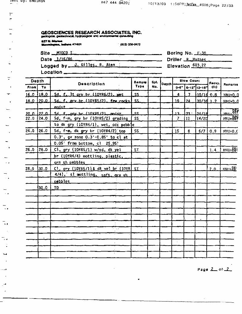
Site MIDCO i Boring No. f-30
Date 1/16/86 Driller R. Hathes
Logged fry
Location
Gilles. R. Aten Elevation 603.22
Dapth
From
0.0
2.0
4.0
6.0
8.0
10.0
12,0
14.0
To
2.0
4.0
6.0
-
u8-°10.0
12.0
14.0.
16-0
Description :
Fill. sd. dk gry br (10YR4/2);
grading to It gry {10YR7/1J qradint
to v dk qrv (10YR3/1) into It vel
br (10YR6/4) into qrv br (10YR5/2).
rocks throuonout. frozen
Sd. m, dk arv br (10YR4/2) aradino
Into vel br (10YR5/4). oraanie sean
0.4' from too. sticks throughout.
moist
Sd. It oily? br (?.SY«;/4l tnpin.V
into peat, blk * dk br (7.5YR3/25
w/root;^ * wood fr&ip*. into «;d. m.
v dk arv (inYR3/ll intrt arv br
MOYRS/?!
sd m prv ^r Mnvp«;/?< w*t
Sd, m, gry br {10YR5/2K into:ra-c.
dk flrv (10YR4/1) bottom 0.15' . wpt
Sd.. arv br (10YR5/21 A dk orv hr
(10YR4/2) mottled top 1.3', «y zone
bottom 0.5' w/sd. It br qrv
(10YR6/2). wet
Sd £ av. arv br HOYRS/?) ton:
1.4' into sd. qrv br (10YR5/2).
little QV qradina to none in botton
0.6'. wetSd. ra-f. arv br (JOYIft/p^ yy 5*»»|n
0.7 '-0.8' from too. sd. f. arv br
SampleTyp«
SS
SS
ss
^SS
SS
SS
SS
SOLNo.
DepthBlow Count
0-6"
60
4
J
1
6
e,
5
10
6-12"
41
. .
7
>
•>
7
7
6
16
12-18
34/17
?/3
1/5
VS.
8/7
«/g
0/13
L?/J5
R«cvyCfl)
1.7
i .n
i t
\.?.
J- 5
1 .R
?.o
1 .?
Ramarki
HNU«0.0
•^i.'Hen
H'lllaHp-1
"'MlcO.0 •
HNU=0
Hwii=n n
HHIIrH rj
(2.5YR5/2) grading to c, gry br
(P.5YR5/2) bottom 0.4', wet Page
oy: tNviHON 847 444 9420;10/13/03 1: 58PM ;;ei&i_#608; Page 22/33
GEOSCIENCES RESEARCH ASSOCIATES, INC.(potogicM. o«atachnical. hydretogicri «nd •fMironnwm coraubng
<«2> 336-OQ72
Site ^Tnr,p T
Date i/Tfi/BfiLogged fry J- Gllles, R. Aten
Location
Boring No. F-3o
Driller »iglevation 603.22
DepthFrom
l^.Q
18.0
?n n22.0
24.0
26.0
28.0
To
18.0
£0.0
?? Q_24.0
26.0
28.0
30.0
30.0
Description
Sdn f. It orv br (10YR6/?>. wet
5d. f. arv hr (10YR5/?). fpw rnrlr*
«!«<<!•
^/1 f ni-y hr- MnVPK/9) fnniff-
Sd, f-m, gry br (10YRS/2) gradingto dk gry (10YR4/1), wet. oce pebbSd, f-m. dk gry br (lOYR4/2) :top0.31, gv zone 0.3'-Q.8S' to cl at0.05' from bottom, cl 25.95'
Cl, gry (10YR5/1) w/sd. dk yelbr (10YR4/4) mottlinq, plastic.qrn sh pebblesCl, arv (10YR5/1U dfc vel br (IOYR4"/4),' si wottling,. soft, orn sh
• pebbles
.TO :
• •-.—
Sampl*TVD«
SS
SS^
<;<;
SS
eSS
ST
ST
Spl.No.
0«pthBlow Count
0-6"
4
15
•p
7
15
6-12-
7
?fl
7"1 '11
8
12-18"
10/lf
30/3fj
?1/U14/2Q
6/7
R«cvy.ao
o.pJ 7
0.9
1.4
?.n
R«rnarki
HhjU=0^0
HMIJ.D n
H»jii-«e'HNU^&f?
HNU=O.C
HNU=8Sic
HNII={1£-
Page 2— at_2_

bent by: tNVlHON / 444 942UJ
ERM-North Central. Inc.
GEOLOGIC DRILL LOG
Fox DrWng-G. Hammond
SAHPtt.oEtne2 feet i 2 Inch Std. Split Spoon
CONTAMINANT SCRtEND* NOTESModel 01 HNu M/II.7 eV lamp/MonHojt (HCNJ
Ira:MIDCOI
Oiedrich 0-50 w/HSA-4.25 inch I.D-BOMNQDIA. (DEPTH (FT)-B" I 26"
CASING 1BHOUM1 ELCV.
HDlE:DUULEN6TH
ELcV. 6HOUNU MA 1ER DEPTH/a£V. TPf OF HOCKNOT ENCOUNTERS)
LOGGED BYCharles Dyer/ERM-N. England
DESCRIPTION AND CLASSIFICATION4eraHy. gr*i Dze/anapc, color, stnct
ce«pos(tiOft. sorttna tertire, Mobtarafade*, odor
brown HOYR8/4).ye|owl«h
06-2.(T: fiRAVPi-- tFMHoark gray («Y«4/1), sotie (Ine sand, poorly sorted,totvent odor.
&0-27.S-: SAMa2A-4.0>: dark gray(WYR 4/0, finestrong totvefit odor.
At ftbove. broNO. (WYR 4/2).
SJ5-6.01: A( above, dark gray (WYR 4/0,welt sorted.6,0-6.0': As above, wet
6.0-K3.31: As above, fine grained withabundant »tei fragments, trace ofgravel, subangular to i cm.
KU-IL5': At abaws. fine to coarsegroined, poorly sorted, trace of finegravel, abundant snal she* fragments.
ILS-12.0': As above, fine grained,homogeneous. t<eD sorted.C.O-J4.0': is above.
D-iao': As above, gray (1QYR S/0.trace of fine gravel, tuoangular to 1 c«.
ctwrwier at drNng.•tc.
Added » galons ofNater: t-2 ppa Inbreathing zone.
Upgrade to Level C•I HOC.
ppa do»«n augers:0 PPM In breathingone.

8 4 7 4 4 4 9 4 2 0 ; 10/13/ua
ERM-North Central. Inc.
GEOLOGIC DRILL LOG RS|sftl' ICOOMWATES"
HIDCQ IJHEGUNICOMICTEO IOMLLEK
03/07/93 j 03/07/03 j Fo« Drllina-G. Hammond
WWJKdHUMBE*82I27EM 2 Of Z
CONTAMINANT SCREEHW6 NOTESMoaef KM HNu w/11.7 ev Igmp/Monlto« (HCN)
SB~2
Oiedrich D-60 w/HSA-4.25 inch ID. 26*
Continued
§ OESdUPTION AND CLASSIFICATION4ic/fhap«, cator, draehraMrttng. teitve, iiototmfacfea.oifar
OMLUN6MOTE6
ttc.
N/12B 2.0
2.0 2.0
2.D
R/tlSy
L/1203
2.0
1.V
i.o
2.0
12213342
B142726
lit)
0.0
""0
0
04J
0.0
ZO-
-26.5'
W.0-t7.0^ *i above, mediim to coartegraineo with 30X fine graret, poorlygraded, «ut>angular to subroundeO grave)up to 2 ec dtameter.tr.0-»,0': AS atwve, tine grained, welwrteo, t«M rne »hel fragments, tracefine gram tuOaogular to Q.SCH.16J-20J)'; As above.
»M-4 downgrade toLevel O; 0 DD« inbreathing tone.
20,0-22.0': As above,•rffom.
22.0-2X.O': A* above, cone fine (hatela«lnatior\, trace very fine ihel
flepteced HNu.Faulty readings onlast ipoon.
Z4.D-26.01: As above.
26.0-26.?: Aj aOove.
: A« above, dark pay (tOYR4/11, Mith fine oravel aedwn to coarsegrained, subangular grave4 to 1 cmdiameter.
27.6-28.01: CU1; gray (WYfl S/1X•cderatery aott.
End of boring at 20 real.
uy.847 444 9420; 10/ ib /ua i i
ERM-North Central, Inc.Ent
GEOLOGIC DRILL LOGIFBOJECT/TASH
2B02
COORDINATES
PROJECT
9212TEMCONTAIUNAHT SCREENIN6 NOTES
Model 101 HNuHIDCO I eV laap/Monitot (HCN)
03/02/83CQKRECOVGRT
rEo03/02/93 Fox Drillng-6. Hamnond Mob* B-61 H/HSA-4.2S inch 1.0
fifKXIND ELEV V. 6AOUNO MTEH
[BOWNSOtt.
-8'06PTH (FTJ28'
SAMPLE DEVICE2 feet x 2 inch Std. spat Spoon
i i ii[DfULLCASlN6L£FTINHOl£:inAAENGfM
OEPTH/ELEV. TOP OF TOCK~NOT ENCOUNTERED
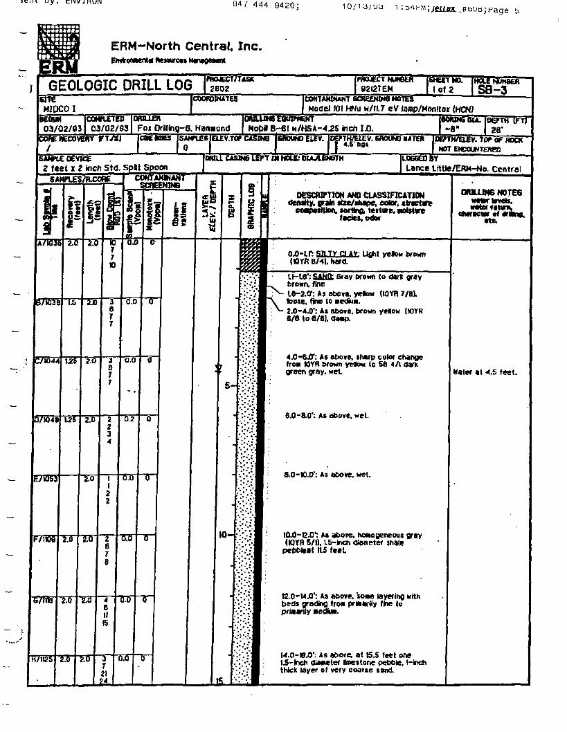
ILDGGEDBYLance Littte/ERH-No. Central
DESCRIPTION AMD CLASSIFICATIONdewtty, oraln ttze/cMpe, color, strvctve
coapoittton. tortnft teitwe, nol$t«re
OfULUNG NOTES
«fMe,
: R« TV ra AV Uflht yelott6/4).(ttYR 6/4). hard
tl-191: SAMP- Gray brown to dark graybrown, fine16-2.0*: As above, yetow (IOYR 7/8).loose, fine to nedw*.2.0-4.0*: Aa above, brown yellow (WYR8/6 to fl/Bl. damp.
4.0-6^*: As above, tharp color changefro* IOYR brown yeflow to 56 4/1 darkgreen gray, wet
6.0-8.0': A* above, wet.
8.0-10.0': As above, wet.
IO.O-I2.Q1: As abore, homogeneous gray(IOYR 5/1). t.5-lncrt Oianeter thale
pcbbleat its feet
12.0-M.O1: As above, «me layering NKhbeds grading fro* primarily fine topriaarily nedluw.
H.O-B.01: As at>ove. at tS.S feet one1 -lnch diaMter Inettone pebble, 1-inchthick Uiyer of very coarse sand.
Hater •( 4.5 feet.
ient Dy: tNVlRON 847 444 9420;10/13/03 1 :b4PM;je|f8a_#608;Page 6
ERM-North Central, Inc.Envt«p*ent« Resftwees MinageHnt
GEOLOGIC DRILL LOG 2602COORDINATES
S2I27EMNO. iHoce
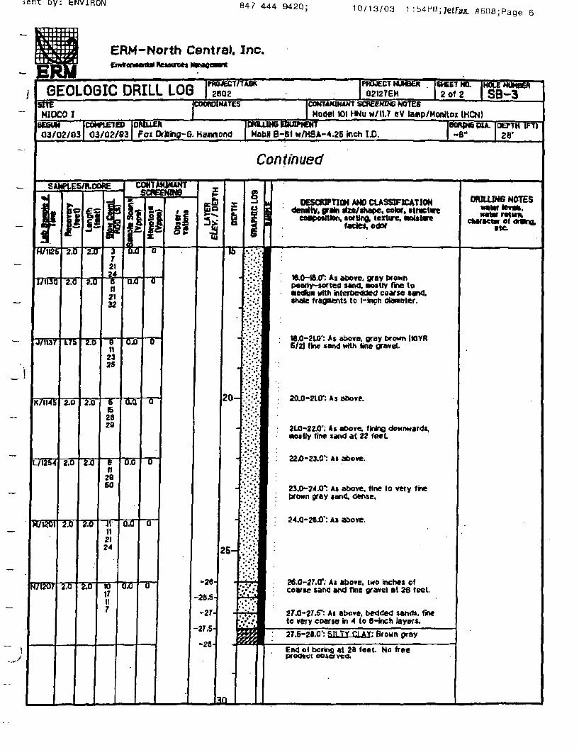
2 Qt 2 | SB-3
E3mAWKAWT SCREENING NOTE6Model 101 HNu w/11.7 ev tamp/Honrton (HCN)MIOCO I
03/02/93COMPIE1ED03/02/93 Fo* PrBing-G. Hammond Mobil 8-61 w/HSA-4.25 inch ID. -8" 28'
Continued
SAHPlES/R.COfC UJMTAMINANTSCREENING
y e §u DESCRIPTION AND CLASSIFICATION
•in size/shape, cotor, ttractinsorting, texture, noJstarefade*, odor
ORILUN6 NOTES
iwtar ratuw.CMfKttr 01
•te.
H/1I2S 2.0
I/U3Q 2.0
J/II37
2.0 J72124
ZJO 6tl2132
0.0
L/I254
M7KOT
2.0
0n
2425
Tff
R7G07
2.0
162829
6n2fiso
JVII2124
04}
0.0 o
TTZT
lo
20-
-26
-2B5-
2S-
-28
tt.0-ia.cr: As »t>ove. gray txownPttorty-sorted sand, Mostly fine to•edHm nith interbedded coarse•hale fragvents to 1-inch
M.0-210': A» above, gray brown (UYR6/2) fine sand with line gravel.
20.0-210*: As above.
2LO-224)': As aDove. finifiQ downwards,•witty line sand at 22 feet
22.0-23.0*: Ai above.
23.0-24.0*: At above, fine to very finebrown gray «and. dense,
24.0-28.0': As above.
26.0-27,0': At above, two inches ofcoarse sarwj and fine gravel at 26 teet.
27.0-27.5*: Ai above, bedded sands, fineto very coarse in 4 to 6-inch layers.
27.6-210': STiTYCLAY: Brown gray
End o< boring at 26 feet. No freeproduct

Sent by: ENVIRON 847 444 9420; 10/13/03 1 :55PM;JetQUL-fftSUa;Page 7
ERM-North Central. Inc.
GEOLOGIC DRILL LOGHTE
CONTAMINANT SCREENING HOTE3Model 101 HNu w'/lU eV laap/Monftoi (HCNl
COMPLETED IvuuknICGvN03/10/M | 03/10/83 D-50 ATV H/HSA-4.2S inch UP.
V.TOPCASIN6 IGROUNDttEV.
INB LEFT IN HOLE: DUULEWSAMPLE DEVICE Harry Ricketts/ERM-No. Centra2 feet i 2 inch Std. SpUt Spoon
SAHH.ES/RCOREORJLUN6 MOTES
DESCRIPTION AND CLASSIFICATIONdcMHy. flraln dze/«hBpe, coter. *tracto«
«of tlnft lertwe, •eistur*fades, odor
HOYB V2»k>ckY. plastic rooti
— '•<
BTifli?
CTibTS
S7T020
£71042
F/UJ65
S71JOT
71300
TT
Tff
Tff T6
K>n
TH2129
T131718
S/8). fine grained. *efl torted.2.0-4.0': At above.
4.0-S.S": As above, howoflcrwou*. wet
: As atxive. very darktxown (WYR 3/1).8.0-8.0': AS above.
8.0-fl.S': As
6.5-KXO': A$ above, medium tofoe-grained sand, aoderately welsorted, trace »caltered smart pe&otes.4t>undant shel fragiients.W J-tZ.O': M above.
ti.O-W.01: As above, moderately sorted.
1: As above, fine-grained tandKith subrounded
IS.6-16.0': Color at above, poorly torledmedivo and fine-flrained sand whhsvbroinded atiad peDt>lea.K.O-IB.O': As above.
IB.O-J9.5'; As above, tone gravel
lfl.6-20.0*: As aoove. thinly iao*wted.
Mater al 4.0 te«t.
Two feet of heavecleared by rotatingHSA.
' i. uy . cixv inuiN8474449420; 10/13/03 1 : 55HM; ;Hage 8
ERM-North Central, Inc.Mnttf fttaoweei Nanaoeaant
•WJECT/7AST2602
PHOJECT NUNBER82C7EMGEOLOGIC DRILL LOG
ICOWTA«N*NT sateeNWe MOTESModel 101 HNu w/11.7 eV lamp/Monitoi (HCN)
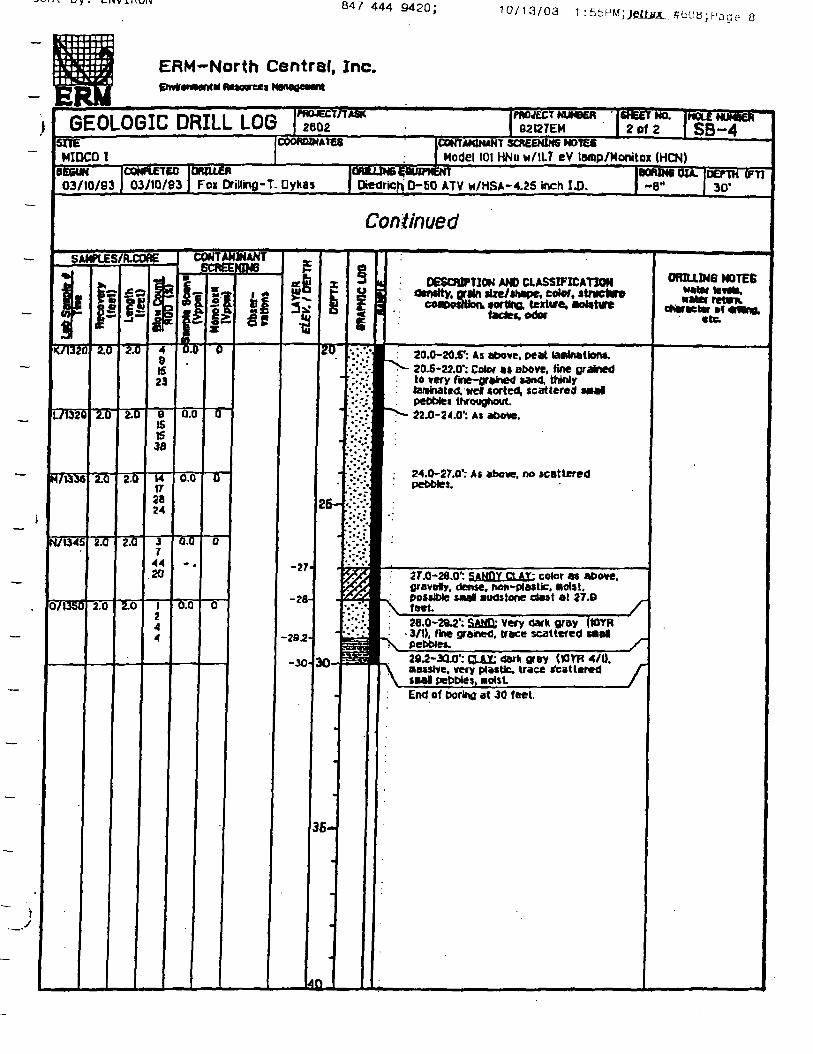
NO. JHOLENUHSET2 Of 2 | SB~4
ftMIDCO I
COMPLETED03/10/63
BRutiSFoi DfiHinfl-T. Dykas03/10/83 ATV H/HSA.-4.25 inch ID. ~8" 30'
Continued
OESOUPTKM AND CLASSIFICATIONowtty. grain itee/Oiape. cotof, «trnetarv
co«CK»«tteni Mrttia leitwe,fade*. o<tof
ORHLIN6 NOTESMterlMto r
cttrictv
20.0-20.5': As above, peat lairirtattont.20.5-22.0': Color a* above, fine grainedt« very fine-grained »and. thinlylaminated, wel sorted, scattered «nalpebbtei throughout.22.0-24.0': AS above.
24.0-27.0': At above, no scattered
27.0-26.0': stMffrctAY: color W above,flravety, dense, non-plastic, nolst.poJiiWe SM« aiidstooe da»t at 27.9feet.28.0-2W: SAMC); very dark gray (WYR
• VI), fine grained, trace scattered mat ,p e b b l e * . / ~
I': OAT dark gray (tOVR 4/0.A massive, very plMUc. trace Mattered
pepp>e»,End of poring at 30 feet.
8474449420 ; 10/13/03 JUH ;Page 9/33
ERM-North Central, Inc.
)| GEOLOGIC DRILL LOGPflMECT/iASK2S02
COOfOINiTES
fWUECT NUMEft82J27EN
CONTAMINANT 5CSEEHWQ NOTESSHEMIOCOI
DfUUE*Foi Drilinfl-T. Dykas
HNu n/ll.7 eV lamp/Honitoi (HCN)
03/06/93COMPLETED03/06/83
CMC me SANTIES ELEY.TOP CASK*Hobl B-61 w/HSA-3.75 inch 1.0.
t^ELEV. BftOUNDWTW
iOU. (DEPTH (FTl28*
COW RECOTOlY (F
CASING UFt W HOLE; OUUUNGTMI«TM
NOT ENCOUNTEREDLOGGED BTHarry Ricketts/ERM-No. Centr
SAMPLE oevjei "~~~feet ( 2 inch StC. Split Spoon
DEBCWPTIOH AND CXASSBTCATIONdetwrty, grain nze/ihape, color, ilrt twe
, torting. texture. ifades, o<tor
DRJLUK6 NOTESMtvrtevtta.
cMrcctcr ofttc.
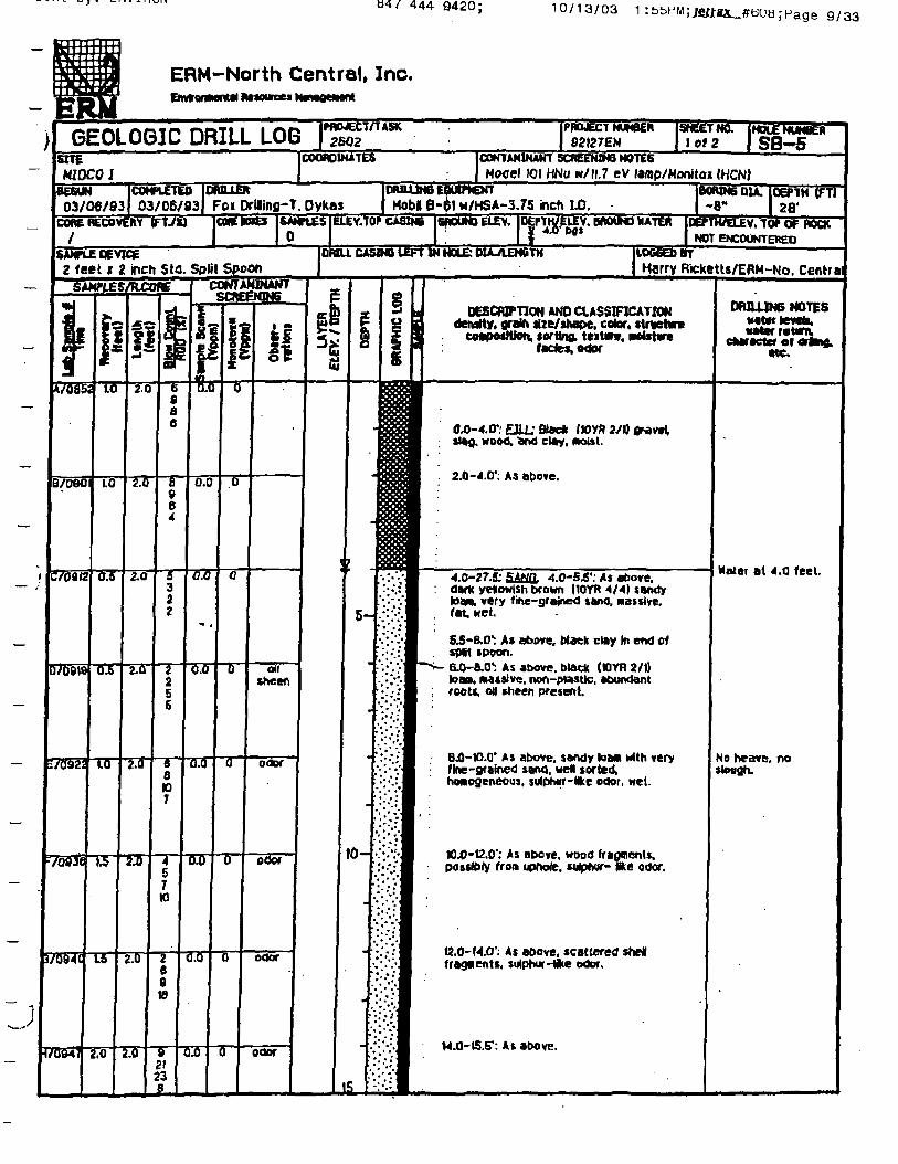
OO-4.0*; EflL- Blade /»Y» 2/1) firetvlslag, wood, fend clay, mist.
2.0-4.0'; AS above.
4.0-27.S: SAtffll 4.0-S^1; As above,dark yeftowish drawn I10YR 4/4) t»ndyIOM. very tine-grained tana, Massive,fat wet.
5.5-B.O1: A* above. Mack clay In end ofspit ipoon.6.0-e.O1: As above, black (K1YR 2/1)loaa. M4«slve. nof\-(Hwtic, abundantroot«, off sheen present
8.0-ia.O' A) above, sandy IQM with veryflne-gramed sana. wel sorted,
s, jufphur-lfce odor, wet.
...D-12.0': As above, wood fragments,possibly from upnote. «4Xwr- ike odor.
.'.'. As above, scattered steKfragnenti. sulpNirHike odor.
M.a-15.5': At above.
Mater at 4.0 feet.
No heave, nosimian.

u y . i_ixv J.HUIN
847 444 9420; 10/13/03 1 : 55PM;;e^^608; Page , 0/33
ERM-North Central, Inc.
PROJECT/TA5T2602GEOLOGIC DRILL LOG 92127EM
SHbklNO. JHOLE NUMElT2 of 2 | SB~5
CONTANIKAKT SCREENING NOTESModel 101 HNu W/IL7 eV lamp/Monitox (HOI)
SHEHIOCO I
COORDINATES
BE6UN03/06/83
DOWtETEO03/06/83 Fox Dflling-T. Dykas Mobil B-61 w/HSA-3.75 inch -8" 28*
Continued
SAHKES/FUCOBEDESCRIPTION AND CLASSIFICATION
deratty. grain tlze/itape, color, ttnictre. tortina techre.
OFUUJN6 NOTES
f ctani,ct«r*eter of «•»«.
rtc
tSJS-lfl.0': Color as above,•edmn to fine-grkined s«oa, •oderateiyturted. xfth large pebbles. «*ptwr-Skeodor.W.O-B.S': Aa above.M -I&JT: As above, sand alternatingwith grarcty MM], coarie tofte-grained s*W, poorly torted-
I8.0-B.(T: As above, dark gray (WYft4/0 uM, fine to nedliw with abundant•hel
tftD-20.0': AS above. flne>gralnea. faint 1r ash-like odor.
2 Vpp« in hole.
20X1-205': Af above.
20.5-22-0": A i above, very we! sorted,trace scattered mall triale fragments.
22.0-24^)': As above.
24.0-2603': AS above.
BVppwinhote. Noheave. f» slough.
no Mater lohole.
M.0-37.5*: A* above.
-. p AY- gray IWVR S/l),•asslve. plailto, scattered iron
Clay at 27.S feet.
£7.8-26.0': S tUULCLAYJ grayS/l). yavety, den*e. noft-pfastte,End of boring at 28 feet
B47 444 9420;10/13/03 1 : 56PM-
;Page ,3/33
ERM-North Central. Inc,I AfetMTCM KmaOMM
GEOLOGIC DRILL LOG HSIffWECT/TASil"
COORDINATES
"PROJECT82127EM lot 2
JCONTAWNANT SCREENING NOTES
! 101 HNu w/11.7 eV larop/Moniton (HCN)
SB-BSHE
HIDCO IteSST03/04/03
COMPLETED03/04/83TFfTiT
Fox OrHfinfl-E. HanwonOEIEV.TOT
MobH B-BI w/HSA-4^S inch ID.V. SftOUNO HATERCOREHECOVEKY
/
TtVCLEV.tOPOFROCK
NOT ENCOUNTEREDLOGGED BY
Lance Uttte/ERH-No. CentralBANTU DEVICE2 feet x 2 inch Std. Spflt Spoon
OESCWPTION AND CtASSHTCATTOHdemlty, grain «fze/ihape, cotor, ctractare
coMpeinioiv K»ftfeg. teiUre, aolatve
NOTES
•te.
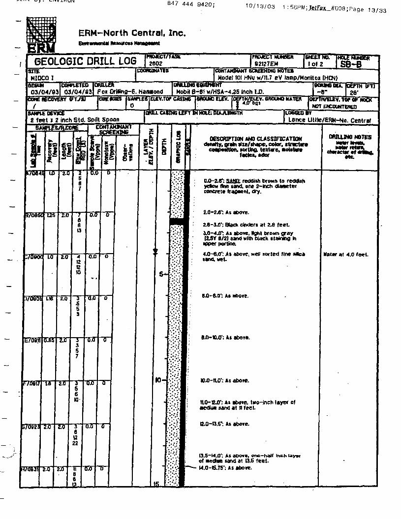
0 -2.8*: SA1P: reddish t>rowt» to retMUfiydtow fine sand, one 2-inch -diameterconcrete fragment, dry.
2.0-2.6': As above.
2.8-10': Black cinders at Z£ feetT. AS above. Nghl troMn gray
(25Y B/2) sand with black stainine inipper portkxv
<JJ-e,0'; At above, well sorted fine sflfcat*nd.Met
B43-8.Q': AS above.
BJ)-tt.O': At above.
-n.O': At aOore.
*; AS above. ti«o-lnch layer ofmedia* sand at n feet.
G.O-O.S*: As above.
U.5-H.O': As above, one-half Inch Uyafof medlwn sand at 13.6 feel.M.O-S.7S'; As above.
Mater at 4.0 feet
uy; tNVlhUN 847 444 9420; io/ ia/03 1 r14/33
ERM-North Central, Inc.
GEOLOGIC DRILL LOGfflOJECT/TAW"
2602COORDINATES
PftMECTNUNK*
82127EM 2 of 2CONTAMINANT SCREENING NOTESModel 101 HNu w/tl.7 eV lamp/Wonftoi (HCN)
NUMBER'
SB-B
MIDCOIOWUJH6 EQUIPMENTMobil B-C1 w/HSA-4.25 inch IJJ.
BONN6BU.03/04/93
[COHPIETEO03/04/93 For OrWng-6. Hammond
IrjEfTHtrtr28'
Continued
DESCRIPTION AMD CLASSIFICATIONmity, grttn iize/*tape, color, itrtctartcMip««ttton. •ortina teitae, •oteture •
fade*, odor
OWLUM6 MOTES
etc.
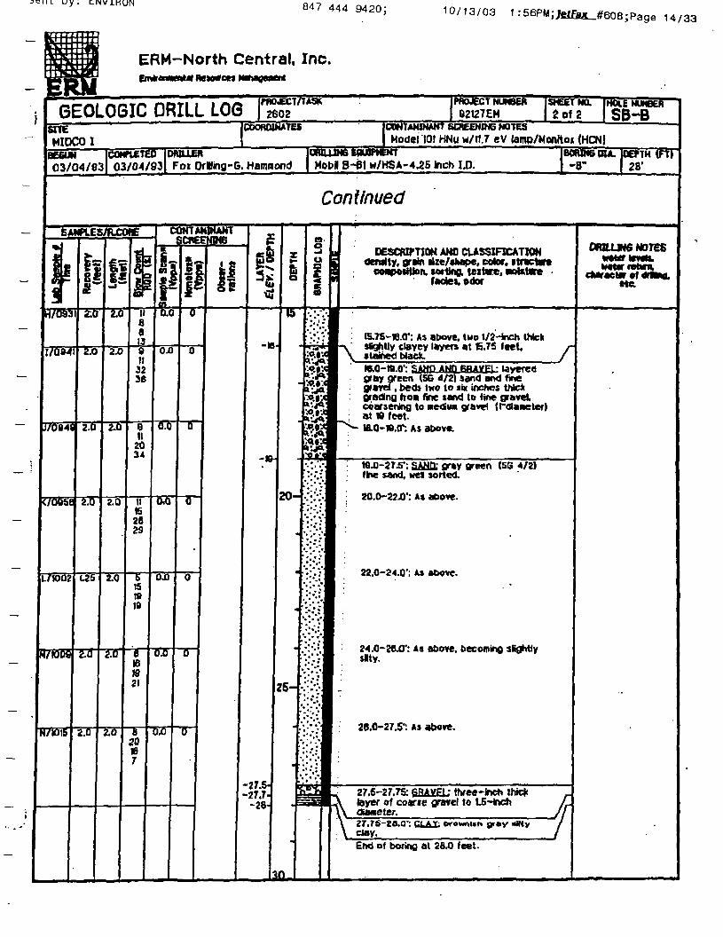
tS.TS'ie.0': As atwrt. two 1/2-teh ihtekN *SgM)y clayey layer* at 6.7S leet, /-i\ »taifte<< btecK _ /
W.O-ta.01: sgray green (56 4/2) »and and fineg»*vri . beds two to six inches thickgrading fro* fine sand to fine gravelcoarsening to mecfu* gravel (roiaaeter)at W feet
*: AS dtwve
tG J-2T54: SANn: gray green (56 4/Z)fine sand, wei sorted.
M.O-22J)1: A» above.
22.0-24.0'; A> above.
$Nty.: Aa above, becoming slightly
20.0-27,5': As above.
27.5-27.75: fiBA^EU three-Inch thk*layer of coarie gravel to t.5-hchdianeter.
clay.End of boring at 28.0 feet.

Sent by: ENVIRON 847 444 9420; 10/13/03 1 :59PM; Jfitfax_#608; Page 26/33
p: ::B • r •
Bl i
ER
f Ht-JI
tilERM-North Central, Inc.Emrornentai Resources Manatxoent
_,__. _,-s««, m«ivi i i /*** PROJECT/TASK PROJECT NUMGEOLOGIC DRILL LOG 2602 g2i27EM
SITEMIDCO 1
BEGUN03/11/93
COMfUETEO03/1I/-93
/
c
iER SHEET NO, HOLE NUN8ER
1 of 2 SB-P»ORDIKATES (CONTAMINANT SCREENING NOTES
| Model 101 HNu w/11.7 eV lamp/Monitox (HCN)
Fw DrilJing-G. HaflWiondc
OMLUN6 EQUIPMENT IBOA1N6DU. DEPTH (FT)Foi-Dledrtoh D-50 w/HSA-4.25 inch 1.0. | -8' 20.0'
Off. BOOS ISANPLES ELEV.TOP CASING GROUND ELEV. DEPIH/ELEV. 6ROUND WATCK 1DEPTH/ELEV. TOP DF BOCK
| 0 f bQI 1 NOT ENCOUNT6REO
SAMPLE te VICE MILL CASINS LEFT IN HOLE: OUA.EN6TH2 feet x 2 inch Sid. Split Spoon
SAMPLES/R.CORE«|
i•-4
tfobiv
J7Be28
VQB3i
E/09&
F7iD02
G/IOIQ
J!
2-0
2.0
2.0
270
2.U
€2
_j^
2.6
2.0
270
2-0
S.O
i£
§«
•4B6B
r~7r7
6S10IS
to202S35
itiis17
701214
~T90fl
12253S
u1
Tii
V?
?|
0
^
^
0
0
0
U
0
1NTANLHEE
Men
otM
M(V
ppn)
WANTNp*3
ii
£
g& X
r
•
5-
•
10-
_j
2QM9
' :•'•" :'"•'•"•"*• •" *
". • .*
". \* ."
.* . .'
-:'•'.•'.'••:•"••" "• * *
;ffl Hr
'. " . V
."-*'"*
/;*X
::;.:
"!*"^
'• " *"•."-::i-l'."•/!••:;J
***.•
*••* i*» * • •*
r?*:* * ^ '
" «
LOGGED BT
Harry Rtcketts/ERM-No. Central
« DESCRIPTION AND CLASSIFICATIONa dendty. grain sbe/ahape, color, •tmctwta coaposlUon, sorting, texture, pobtire^ fades, odor
1 0.0-0.5'tlLL; very dark brown1^^ : 2/2} loany clay topsol and hi.
IWYR
0^-25.rSAJtift Mack (IOYR 2/1). fine to•edim grained, nocerately sotted,homogeneous, moist.
2.0-4.0': As atwve. no strvctures visible,net
• 4 0— S fi** Aft AbAvp
S£-6.0':SANDY lOAl* very dark- (OTR 3/t), fine-grained sand, nV thMy laoiinaled wiWi jWt
flray0»l. r
6.0-13J'. SAMD: WaO (UYR2/1).
7X-8.0': As above, dark gray (IOYR
B.0-9.0': As above, coarse to finegrained, poorly sorted.
9.0-W.O1: As above, fine to very finegrained, Mel sorted, ihln laninations.
W^-tt.0': As above, fine to nedlungrained, Moderately sorted, scattered
: very snail pebbles, texture finesdownward.
tt.0-l3.fl': As above, fine to very finegrained, well sorted, thin laminations.
-. 13.8- U.O': stNnY BRJVPL: smalV and coarse sand, supangular to
gravel /-
U.O-M.8*: SAND; dark gray (OYR 4/1).
DRR4JN6 NOTES
ehw Acter of drNno.etc.
«
Water with driBreturns has oil-Ikesheen.
Bent by: ENVIRON 847 444 9420;10/13/03 1:58PM;Jetfitt_#608;Page 25/33
4
—
_ I
J
^
mfA ERM-North Central, Inc.Ertdronaental Reseurtes Manageaent
GEOLOGIC DRILL LOGSITENIDCO I
BEGUN03/11/83
COMPLETED03/I1/-83
2602COORDINATES
r
DRILLERFox Driling-G. Hammond
92I27EM 2 of 2 SB-PCONTAMINANT SCREENING NOTESModel 101 HNu w/ll.7 sV lamp/Monitox (HCN)
DMLUN6 EWtfNENT . BORING DIA. OETTH '(FT)FoJt-DiedrlCh D-SO w/HSA-4.25 inch I.D. -B" 28.0'
Continued
SAMPIES/R.C0I*
*J
ai
H/KJ20
171325
K/IQ41
L7U550
••2.0
2.0
2.0
2.0
J.fl
!i2.0
2.0
2.0
2.0
S.fl
ifir25as
14
2S
13151719
11IS1720
6it10B
7SBa
CONTAMINANTGREENING
P
0
0
0- .
0
0
*_
is
E
Cjo2*T
-19.2--19.S-
-21-2L3-
-22
-2C-
ili
25-
o
§ ii DESCfUPTION AND CLASSIFICATIONd density, grain size/shape, color, siructwe9 coaposrtkrtv sorting, texture, notetw*"i factes, odor
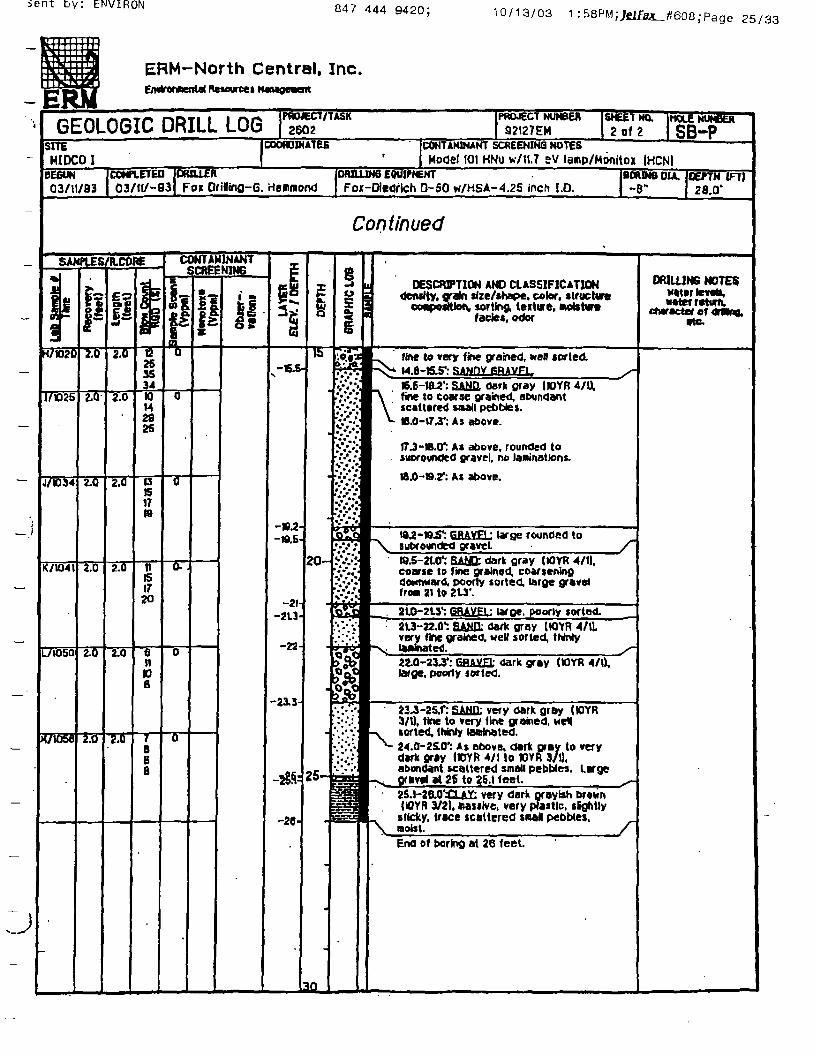
•«.«*W^ fine to very fine grained, wen sorted.'Itf.p v^* M fl-IS 5*- SA.NfJY PRAVFL, ^
££
£•*•••'
••* •"."•s&k
%v"-*
1&
1=s=
I B.C-iaa': SAN.Q. dark gray |K)YR 4/U,|\ fine to coarse grained, abundant• V scattered snail pebbles.I *~ tB.0-174': As above.
1 17J-W.O*: AS above, rounded toI suorounoed gravel, no laminations.
I8J5-S.?: As above.
K 19 -19 gptygl ;subrounded gravel
large rounded to
W.5-2101: SAtSt dark gray (tOXR 4/t|.coarse to fine grained, coarseningdownward, poorly sorted, large gravelf row 21 to 2U'.
2LO-•2L3':SRAYpl1: large. i>oorly sorted.2L3-22.0": &A1U1 dark gray IKttR 4/1Lvery fine grained, well sorted, thinly
-V laftinated. ^~22.0-23J4: 6H&VF1: dark gray (UYft 4/1),large, poorly sorted.
«J-2S.f: £AMIL very dark gr&y (WYR3/1), tine to very fine grained, we*
^ sorted, (hinry (eerinated.^- 24.0-25.0': As above, dark gray to very
dark gray IIQYft 4/1 to ttrfi 3/1),abondaflt scattered small pebbles. Large
-s, Of»ve« at 26 to 25.1 feet. ^-2S.1-2e *£U£ very dark grayish brownlOYfl 3/2). oasitve, very pfastlc. slgfitly
_ sticky, trace scattered snal pebbles, ^T\ moist. fJ End of boring at 26 feet.
DWLUN6 NOTESwaterier**,water return.
cMracter of omno.etc.
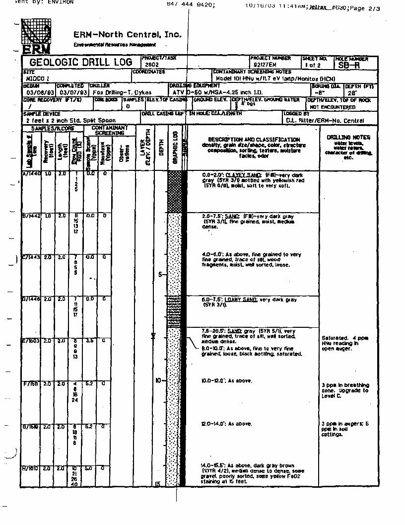
>ent oy: bNViHON H4/ 444 9420\ 10/ ib /ua
ERM-North Central, Inc.£nv»t**er*at Resource* Manaoawnt
GEOLOGIC DRILL LOG
K6UN (COMPLETED
03/06/83 03/07/63DRILLERFox Drilling-T. Oykas
DOm RECOVERY FT/XJ
SAHTVS DEVICEfeet x 2 inch Std. Split SpoonSAMPUS/RCORE CUNI AKIN AN I
SCREENING
10.0-C.O': As atx>ve.
2/3
S2I27EMSHEET MX
lot 2CONTAMINANT SCREENING NOTES
Model 101 HNu H/U.7 eV lamp/Monitoi 1HCN)
HOLE NUMBER
SB-R
-50 vr/HSA-4.25 inch I.D.GROUND ELEV. JOEPTH/EIEV. GROUND WATER |DErTH/ELEV. TOT OF ROCK
NOT ENCOUNTERED.LOGGED BY
CU. Rilter/ERM-No. Central
DESCRIPTION AND CLASSIFICATIONden$fty. grata 4Ue/itiaoe. color, «tr«eUre
»or ttno, tertare,fade*, odor
WOUJW NOTES
tie.
OJJ-a.0': CLAlEX-SAtC: (FBhwy darkfiray (SYR 3/0 nottted with yelowish red(SYR 6/8). nolst, Mft to very sof I.
2.0-7.5'.' SAWD (FMhvery d«rk gray(SYR 3/tL fine grained, noUt. nedlu*
dense.
4D-6.0': A* above, fine grained to veryfine grained, trace of «lrt. woodfragments, octet, wel sorted, loose.
6J]-7.5': p*MY SAUfl; »efy dark gray(SYR 3/U.
7 -26.5*: s*Mn- gray (SYR 5/1). veryfine grained, trace of slit, wel sorted,nedium dense.
-; As above, fine to very finegrained, toote, Wack aottUna. saturated
C.O-W.O': A« above.
Saturated. * PP«HNu readinfl Inopen auger.
3 PPM in breathingtone, upgrade toLevel C.
3 ppft in augers; 5ppnlnsoilcuttings.
v4.0-1S.iT: At atwte. dark gray brown(1QYR 4/2), me<Suo dense to dente. some
gravel, poorfy sorted, some yeflbw Fe02staining at tS feet

oeni. oy: tiwiHUNH4/ 444
3/3
wnthiiIfLII fl
1HIMJU 1 1 I 1 U ERM-North Central. Inc.
— IE
—
"
.J
ff\M Mental Resources Manageaeni
GEOLOGIC DRILL LOG TewSITEMIOCO I
03/06/83COHPLETEU03/07/03
SAMPlES/FLCOAE
jI
HVlBlO
I/W2O
K/B30
70B4f
V085S
N70B13
SJ
2JQ
2.0
2.0
2.0
2.0
|I
i.0
2.0
2J3
zTo
2.0
lo
I?£1
•i
P
"Ib21
40&
27SD/51
B223045
tt2324
B1422Zfi
Bt212a
576fi
COORDINATES
OMLLERFox Drilling-T. Oykas
PROJECT NUMBER SHEET NO." HOLE DUMBER ~"92I27EH 2 of 2 SB~R
ICONTAHINAm SQREENINe NOTES• | Model 101 HNU w/IU eV lamp/Honitox (HCN)
WttUJND tiWtfcWT BORING OIA, DEPTH (Ft)ATV qi-SQ w/HSA-4^5 inch I.D. ~B" 28'
Continued
CONTAMINANTSCfiEENTNS
Sam
ple
Sca
n*(V
ppm
l
4.0
~2,0
18
0.0
rjj)
0.0
P0
0
0
0
0
0
ii£
1
-28.8-
-20-
iIb
20-
25-
•
n
OT
AP
HIC
LOO
***.*
•- •/.'•,.""''*,*. 1» .".
. ••* '
''."" *"
DESCRIPTION AND CLASSIFICATION3 denttty, grain Hzc/shape, color, »tnctw»1 ccaposWon. sorting, tektere, Molstm1 fade*- Ador
1 tS -17.01: As above, very fine to fine1 grainect Mel sorted.
17.0-0.0': As above, grayist* brown(IOYR S/2), trace of gravel, gastropods.
ia.0-20-0': AS above, trace woodfragnents
20J3-22^T: As aoove,
22.0-24.0'. As above, gray (SYR B/l).shew fragment i.
24.0-26.01: As above, gray (SYR 6/1}.trace of fine gravel subangular to 1 c*.laminatlocu at 24.? (0.4 c«|.
28.0-26.5": No recovery. ResampleInterval (clay present in shoe].
2S.S-2B.O': CUJC; gray (5YR C/l) neoiiMstiff to stiff, soflie gravel, angular, poorlysorted. Fe02 staining at 27.0 feet.
End of bortrtg at 28 feet StreliQfBpNcDOTlna gtoitica Kith Ocntanit« slurry.
oraaiNs MOTESnatar levels,tw^retarn,
ClUf ACta9f O* wMMLete.
0840 doMngrade toLevel 0; 0 ppw inbreathing tone.
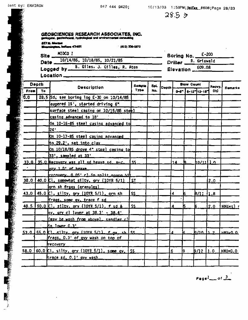
5ent by: ENVIRON 847 444 9420; 10/13/03 1 :59PM;JelEsK_#60B;Page 28/33
GEOSCJENCES RESEARCH ASSOCIATES, INC.potogial. •MtMhnidl, h»o>o4ogical v* tnHnnm*** comtftfng
fZ7N.MortM^^^^^^^^^^^^^_ ^M^UA^ B A^ fil•PB^P^^^^^^^W* ^™^ ^ * ^r — — •
Site HIDCO I E"2QQ
10/14/85» 10/18/85, 10/21/85
Logged by.Location _
B. Giles, j. G111«$, R. Aten
Boring No.
Driller R- GHswald
Elevation 609-oa
\i Depth£ From
kor*.-
1
33. H•
38.0
43.0
48.5
53.0
58.0
To
28.5 Sd, see boring log E-30 on 10/14/85
Sugered 15', started driving 6"
urface steel casinq ot\ 10/15/85 stcasinq advanced to 18'
1 Sxmpi*1 Tyco
I1I
n 10-16-85 steel casinq advanced to24*
On 10-17-85 steel casinq advancedto 29. 2' , set into clavOn 10/18/85 drove 4" steel casino to
33* T samoled at 33'
3f,0 Recovery waj pll *d h^av» «;rl m-r.
nry 1 fl' *rf h«au»
("ppftUATJ/. fl 0*i( rl in <plit «pnnr» K<
40.0 Cl. somewhat siltv, qrv (10YR 571)qrn sh fraqs (qranules)
45.0 Cl, silty. qrv (10YR 5/1). qrn shfraos, some qv. trace f sd
50.0 Cl. slltv. orv (10YR 5/1). f sd &lav. orv cl laver at 38.3' - 38.4'(njav be wash frnm abnvp) . <:»nrHpr rl
Hn lower 0.3'
«;«; n In ,«Mitv. nrv MOYP «i/n f nv «s(fraqs, 0.3* of qvy wash on top ofrecovery
60.0 Cl. silty. qrv (10YR 5/1). some qv.trace sd. 0.1' qvv wash
^5
ST
SS
ss
<;<
SS
r "•"• Blow Countt , 0*ev»
0-«-
14_
4•
4
A
6
6-12"!1*1*"1 <»d
•
.
Q
5
10/11
J/JJ
5 ;
)
j/m
>/12
1 0
2.0
1.8
Z.O
1 7
1.0
• flmwki
HNU-sl r
MNII=Q n
HNU-0.0
PageJ . o f .
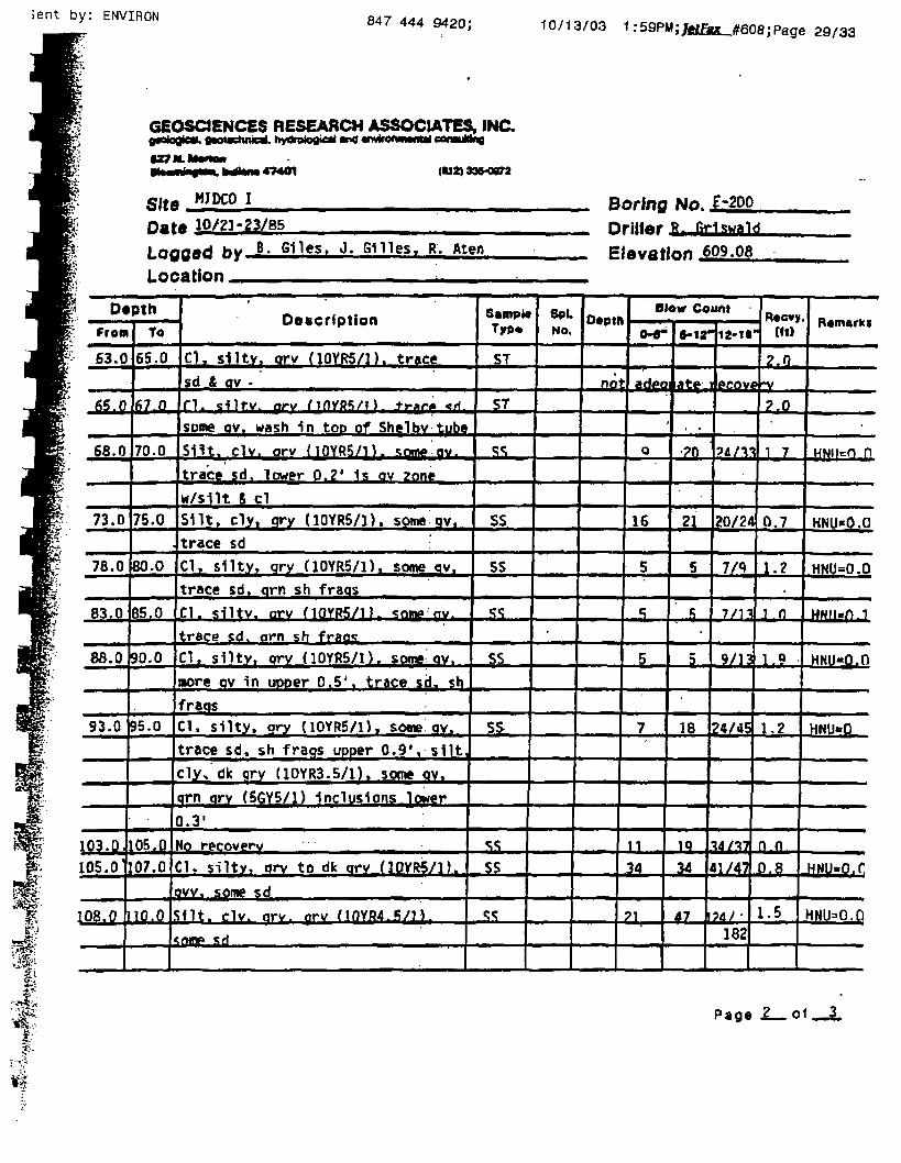
Sent by: ENVIRON 847 444 9420; 10/13/03 1:59PM;JetEag^_#60a;Page 29/33
GEOSCJENCES RESEARCH ASSOCIATES, INC.
147401 (U2| 33*0072
MJDCO ISiteDate 1Q/21-23/85Loggod fry B- SHes. J. snies. R. Ateo
Location _ •
Boring No. E-2ooDriller &Elevation
* Depth• From
63.0
65.0
68.0
73.0
78.0
83.0
88.0
93.0
103. (L105.0
108,0
To
65.0
fL7i°
70.0
75.0
80.0
85.0
90.0
9 .0
OB.O
07.0
10.0
ftfififffniinn
Cl, siltv, qrv noYR5/l). tracesd & av -Pi. s*lfv. prv f|nYR5/l)r trflr* «rt.
some ov, wash in too of Shelbv tubeSilt. civ. arv MOYRS/ll. som* av.
trace sd. lower 0.2' 1s ov zone
w/s1lt & cl51 It. cly, gry (10YR5/1). some qv.trace sd •Cl. sllty, qrv (10YR5/1), some qv.trace sd, qrn sh fraqsCl. siltv. orv (10YR5/11. ^ome ov.trace sd, orn 5h fraosCl, siltv. orv (10YR5/1). someiqv.
more qv in uooer 0.5', trace sd. shfraqsCl. silty. gry (10YR5/1K some: qv,
trace sd, sh frags upper 0,9', silt,
cly, dk qry (10YR3.5/IK some qv.
qrn qrv (5GY5/1) inclusions Ipper0.3'
No recoveryCl. siltv, qrv to dk qrv (1QYR5/1).
ovv. some sd
?11t. civ. arv. orv finYR4.5/11.
^pmp sd
SempteTyp«
ST
ST
«?^
SS
ss
ss
ss
ss
<;<;ss
<;<;
SOLNO.
Oeptti
n9l
Blow Count
*4*
a4fi<7
Q
IB
5
«;
5
7
Jl
34
?1
e-iz-
ate,_J
. ,
•?fi
21
5
c,•
j
18
iq34
47
Il2-t«
PCOV*
jReevy] HI)
1 2.0
ivU.O
?6/\1 ] 7
20/24
7/9
0.7
1.2
7/iJj n
9/13
24/45
_
1,9
1.2
™/37J n n41/47)
•>&.! •182
0.8
1.5
Remark*
•
HNIIcO 0
HNU^O.O
HNU=0.0
Hfftl'P 1
HNU-0.0
HNU»0
HN\J-0.^
HNU=0.0
Page
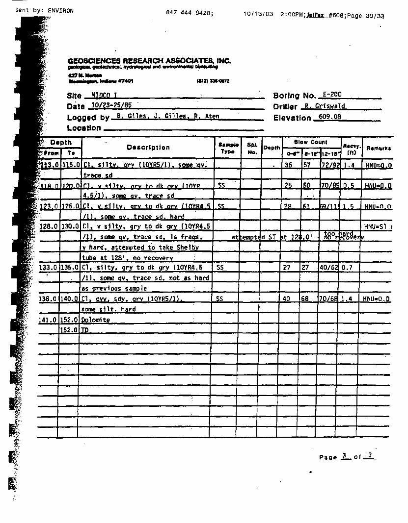
Sent by: ENVIRON 847 444 9420; 10/13/03 2:OOPM;Jfitfja_#608;Page 30/33
GEOSCtENCES RESEARCH ASSOCIATES, INC.
Sltd MlDCO T
47401 (132) 39*0172
10/23-25/85Boring NQ £-200Driller R. GHswald
Logged hy B. Giles. J. Gillgs. R. Aten
LocationElevation 609.08
BpTo*E: —B^P'«w
6«3.0
rl^J^iD
ijM.O
§ iJZS.O
/:•
fr
:: 133.0r-
138.0
141.0
pth••••M
To
115.0
1TO.O
]?5.0
130.0
135.0
140.0
152.0152.0
.
Description
Cl. slltv. orv (10YR5/1). some :av.trace sdn. v <;-ntv. irv to dk pry MOVR
4.5/1). some av. trace sdCK v slltv. arv to dk orv MOVR4.5/I), some av. trace sd. hardCl, v sllty, gry to dk qry UOYiR4.5
/I), some qv, trace sd. Is fraos,
v hard, attempted to take Shelby
tube at 128', no recoveryCl, silty. gry to dk gry (10YR4.5
/I), some qv, trace sd. not as hardas previous sample :Cl, aw, sdv. orv (10YR5/1Ksome silt, hard
Dolomite :TD
S«mp4«Typ»
SS
ss
at
SS
SS
SpLNa.
:emDt(
O«pth
•
d ST
Blow Count
**"35
25
?R
it 12
27
40
B-lHl2-16
57 172/95
50 I70/8E
pi Iw/n
.0'
27
68
Ij80r
40/62
. Rcevy" (ft)
? 1.4
0.5
Jl 5
leaver
0.7" 'I
70/6fi| 1.4
R«m«rK«
HNU-0.0
HNUeQ.O
HNii=n.n
HNU=S1 »/
HNU-0.0
Pao« 3 Q t . . 3

UJ
0
-32
ui —Q
5
10
15
20
25
30
35
40
SAMPLES
NO. BLOWSPER 6"
o
0
•':'
,",*
::'
•:!
•.•;••.
...
•y.i
\
DESCRIPTION
Fine to Medium SAND.
220
Dense Brown SILT with Some FineSand.
29.O
Brown Plastic CLAY.
Boring terminated at 32 feet.
Date Drilling Started: 1 Oct 03 Ended: 1 Oct 03Drilling Contractor: Contract Dewatering Services, Inc. (CDS) v'°"Driller: DN Ins
Notes: 1. Boring located at cer2. HNu Readings l-2pi
HCN Readings Oppm3. 6-inch solid flight au4. Borehole backfilled \\
pector:
iter of south side,im by CDSby CDS
<rz >- — ~
0 CO
HE
SIO
N(p
sf)
STANDARDPENETRATIONRESISTANCE
Blows per Foot
10 20 30 40
tract Dewatering Services, Inc.
Midco I Slurry Wall
Gary, Indiana
gers used for drillingvith auger cuttings ^ LOG OF TEST BORING NO. CDB-1

SgLJJ
0
-32
tHQJ
Q
5
10
15
20
25
30
35
40
SAMPLES
NO. BLOWSPER 6"
o
11IEO
" I • ." •
;ifj;
:•!!•!:•'" : :" .' '"
• ; : ; •
:::"::
.* * .* ; .*
.-•:•:.•
•.•:•.{•:: :: :;
.'.'.! :.'.
'.•.:::..* •. '.'.."
• \ :*..••
' " :' :
:"::::"•
:"::•:"•
DESCRIPTION
Medium SAND.
250
Fine Brown SAND.
27.0
SILTY SAND.
290
Brown SILTY CLAY.
Boring terminated at 32 feet.
Date Drilling Started: 1 Oct 03 Ended: 1 Oct 03Drilling Contractor: Contract Dewatering Services, Inc. uon
Driller: DN Inspector:
Notes: I. Boring located at cen2. HNu Readings 6-7 pp
HCN Readings 0 ppm3. 6-inch solid flight au±4. Borehole backfilled n
ter of west side,m by CDSby CDS
K1EZ
Si?58
o^SoZ 0."uj —
Q CO
HE
SIO
N(p
sfl
STANDARDPENETRATIONRESISTANCE
Blows per Foot
10 20 30 40
tract Dewatering Services, Inc.
Midco I Slurry Wall
Gary, Indiana
{ers used for drillingith auger cuttings ^ _| ^ LOG OF TEST BOR|NG NO. CDB-2

u><£_i —LU
0
-32
I
o.£LU —O
5
10
15
20
25
30
35
40
SAMPLES tj
NO.
IBLOWS <PER 6" g
'. ;
; ;
•;•
:;•
•'•.
:'-
•':':
.-•[
:.':!
.:.:.;
' '
'
o DESCRIPTION—1
•:": Brown Medium SAND with Trace Fine:.;: Sand.
•:.-•: .'.'
• {;'
\ i \
': f 1
'• :' '•
•{:'
!:.•
: : :
:: : 20.0
Fine Brown SAND.
25.0
iii SILTYSAND.
: ! : 27.0
' Brown SILTY CLAY.
/
Boring terminated at 32 feet.
Date Drilling Started: 1 Oct 03 Ended: 1 Oct 03Drilling Contractor: Contract Dewatering Services, Inc. vo"Driller: DN Inspector:
Notes: 1. Boring located at c2. HNu Readings 4 pp
HCN Readings 0 pp3. 6-inch solid flight c4. Borehole backfillea
enter of east side.>m by CDSm by CDS
^UJlU
$Z*58
irintjo££
o CO
HE
SIO
N(p
sf)
STANDARDPENETRATIONRESISTANCE
Blows per Foot
10 20 30 40
tract Dewatering Services, Inc.
Midco I Slurry Wall
Gary, Indiana
mgers for drilling' with auger cuttings LOG OF TEST BORING NO. CDS-3

£jgLJJ
0
-29
-32
I
oIHLU —0
5
10
15
20
25
30
35
40
SAMPLES
NO. BLOWSPER 6"
u
GR
AP
HI
LOG
•;;i^.":':::
.':':••
.'::.' :
'•:'•:.•" • " ', •
":':•;
:: : '•
: :::'
.:'.::,
•!•••!•'.•.'.; .'.'.*
i 1 ' /
> ' ' /
DESCRIPTION
Gray Medium to Fine SAND.
15.0
Brown Medium to Fine SAND.
20.O
Fine SILTY SAND.
27.0
Gray SILTY CLAY with Sand Varves.
29.0
Brown SILTY CLAY.
Boring terminated at 32 feet.
Date Drilling Started: 1 Oct 03 Ended: 1 Oct 03Drilling Contractor: Contract Dewatering Services, Inc.Driller: DN Inspector:
Notes: 1. Boring location is cer2. HNu Readings 4ppm
HCN Readings 0 ppm3. 6-inch solid flight au±4. Borehole backfilled w
tier of north side,by CDSby CDS
*ZUJUJ
$$*58
cc.(Q~GCjZ Q."QJ —
0 CO
HE
SIO
N(p
sf)
STANDARDPENETRATIONRESISTANCE
Blows per Foot
10 20 30 40
tract Dewatering Services, Inc.
Midco I Slurry Wall
Gary, Indiana
>ers used for drillingith auger cuttings ^ ^ LOG OF TEST BORING NO. CDS-4


TABLE 1-3
I
RANGE OF CONCENTRATIONS OF COMPOUNDSDETECTED IN SOILS, SEDIMENT, GROUND WATER, AND SURFACE WATER
DURING THE REMEDIAL INVESTIGATION0*MTOCOISTTE
GARY, INDIANA(Page 1 of 4)
| Compounds
Aluminum
Antimony
Arsenic0*
\ Barium •
Qery Ilium
Cadmium
Calcium
Chromium
Cobalt
Copper
Iron
Lead
Magnesium
1 Manganese
Mercury
Nickel
Potassium
Selenium
Silver
iSodium
Thallium
Tin
Vanadium
Zinc
Acenapbthcoe
Acenaphthyleoe
Acetone
Soils™(mt/kf)
458-31100
ND-103
ND-49
ND-1090
ND-3.4
ND-17
230-103000
ND-10200
ND-20
ND-29200
1280-69900
2.4-4980
8.81-62400
ND-537
ND-3
ND-6620
ND-5400
ND-3.5
ND-11
ND-20500
ND-1.2
ND-470
ND-81
3.1-7860
ND-26
ND
ND-480
Sediments(me/kg)
3370-35100
1.70-18
1.6-69
50-651
ND-7J
0.84-21
4470-S2400
65-1600
ND-20
17-1180
8350-45800
28-1420
1100-21500
76-1770
ND-2.6
7.2-805
391-3920
ND-3.4
ND-5.3
524-16800
ND-19
1.80-24
9.9-56
82-933
ND-0.24
ND-0.5
ND-17
Ground Water(mg/l)
0.027-413
ND-0.022
ND-0.066
ND-11.4
ND
ND-0.022
3.05-1270
ND-5.95
ND-0.091
ND-1.28
0.064-187
ND-0.295
0.182-385
0.004-6.81
ND-0.0015
ND-34.1
33-486
ND-0.04
ND-0.041
14.4-27600
N&0.05
ND-1.31
ND-0.15
ND-3.11
ND
ND
ND-30
Surface Water(mf/\)
0.08-6.19
ND
ND ).031
ND-036
ND
ND-0.011
135-239
ND-0.14
ND-0.023
NDO.497
0309-96.4
OJ0067-0.252
3.17-743
0.023-3.08
ND-O.OOll
NDO324
1-29.8
ND
ND4.02
0.443- 159O
NDX).007e
ND4.025
ND ).05
0.03-0.45
ND
ND
ND0.59

cTABLE 1-3
RANGE OF CONCENTRATIONS OF COMPOUNDSDETECTED IN SOILS, SEDIMENT, GROUND WATER, AND SURFACE WATER
DURING THE REMEDIAL INVESTIGATION'"MTOCOISITE
GARY, INDIANA(Page 2 of 4)
—
—
jT
( )/
II
|
f
f
f
f
rffff
r l_, fP| 2
Compounds
Anthracene
Benzene
BenzoOOanthncene
Benzo(a)pyiene
Benzo(b&k)flooranthene
Benzo(g.lu)perylene
Beozok acid
Benzyl alcohol
Bis(2-chloroethyi)ether
Bis(2-«thylhexyl)pbthalate
2-Butanooe (MEK)
Carbon disulfide
Chhnbatzene
Chlordane
Chloroc thane
Chlorofonn
Chrysene
Cresol
4,4'-DDD
Dibenzo(a4i)antfaracene
Dibenzofuran
1 ,4-Dichlorobenzene
1,1-Dichloroethane
1,2-Dichloroethane
1,1-DicbJoroethenc
Trans- 1 ,2-dichloroethene
.,4-DichlorophenoI
Soib01
(mg/kt)
ND-2IO
ND-14
ND-64
ND-29
ND-68
ND-18
ND-68
ND
ND
ND-1300
ND-880
ND
NCMS40
ND-14
ND
ND-O.Q22
ND-64
ND-11
NtK).0068
ND-6.4
ND-22
ND-0^9
ND
ND
ND
ND-2.6
ND-0.057
Sediments(mg^g)
ND-l.l
NIM).0042
ND-1.8
ND-1.8
ND-3.4
ND-0.72
ND-32
ND
ND
ND-44
ND
ND
ND
ND-1.6
ND
ND-0.00980
ND-2
ND-1.6
ND
ND-0^1
ND-0.23
ND
ND-.047
ND ).0039
NEW).014
ND-0.011
ND
Ground Water(mj/l)
ND-0.004
ND-6.8
ND
ND
ND
ND
ND-130
ND^).l
ND-0.023
ND-0.029
ND-84
ND-0.0091
ND
ND
ND-2
ND-2.7
ND
ND-0.88
ND
ND
ND
ND
ND-0.82
ND-0.1
ND-0.1
ND-7.7
ND-0.0048
Surface Water(mg/1)
ND
ND-0.012
ND
ND
ND
ND
ND
ND
ND
ND-0.0022
ND-0.1
ND
ND
ND
ND-0.036
ND
ND
ND-0.014
ND
ND
ND
ND
ND-0.075
ND-0.014
ND
ND-0.087
ND

\TABLE 1-3
RANGE OF CONCENTRATIONS OF COMPOUNDSDETECTED IN SOILS, SEDIMENT, GROUND WATER, AND SURFACE WATER
DURING THE REMEDIAL INVESTIGATION*MTOCOISITE
GARY, INDIANA(Page 3 of 4)
1 Compounds
2,4-Dimetbylpbenol
Eodrin
Ethyl benzene
| rluonntnene
Fluorene
Iodeoo( 1 ,23-cd)pyreoe
Isopbofonc
2-Methylnaphthalcne
Methylene chloride
Naphthalene
Nitrobenzene
N-NitrosodJphenylamine
PCBs
Ipentachloropbenol
Pbenaothreoe
Pbeaol
Pynot
Styrene
1 , 1 ,2,2-Tetrachloroethaoe
Tetrachloroetbeoe
Toluene
1 ,1,1-Trichloroetbane
Trichloroetheoe
Vinyl chloride
Xyleoc
2-Hexanooe
4-Methyl-2-pentanone
Soils"(nufcj)
ND-0.28
ND-4.4
ND-3100
ND-I60
ND-23
ND-14
ND-81
ND-140
ND-3600
ND-260
ND-0.045
ND-0.26
ND-44
ND-26
ND-160
ND-5000
ND-110
ND-280
ND-0.0086
ND-350
ND-4100
ND-230
ND-840
ND
ND-3500
ND-72
ND-530
Sediments(mt^t)
ND
ND
ND
NIM
ND-Q31
ND-0.49
ND-2,6
ND-1.2
ND-0.830
ND-0.90
ND
ND-OJ90
ND-10.4
ND-OJ1
ND-2.1
ND-3.7
ND-3.1
ND
ND
ND
0.14 ).043
ND-0.0160
ND
ND
ND-0,15
ND
ND
Ground Water(mt/l)
ND-0.16
ND-0.0005
ND-1.9
ND-O^XX3
ND
ND
ND-U
ND
ND-320
ND-0.022
ND-0.0028
ND-0.003
ND
ND-0.079
ND-0.0052
ND-37
ND
ND
ND
ND-OJ7
ND-46
ND-7.6
ND-0.91
ND-3
ND-11
ND-OJ25
ND-34
Surface Water(mg/1)
ND
ND
ND-0.0042
ND
ND
ND
ND-0.025
ND
ND-0.12
ND
ND
ND-0.0026
ND
ND
ND
ND
ND-0.0026
ND
ND
ND
ND-0.44
ND-0.023
ND-0.016
ND-0.015
ND-0.17
ND
ND-0.069
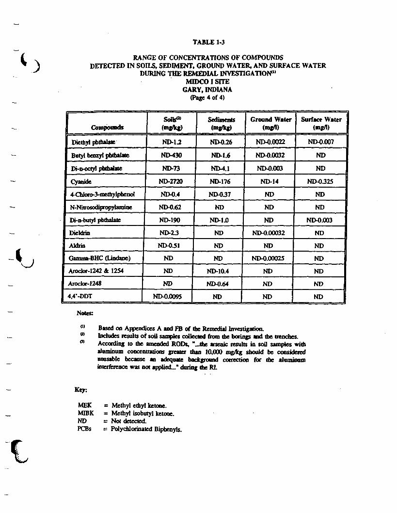
\
TABLE 1-3
RANGE OF CONCENTRATIONS OF COMPOUNDSDETECTED IN SOILS, SEDIMENT, GROUND WATER, AND SURFACE WATER
DURING THE REMEDIAL INVESTIGATION*1'MTOCO I SITE
GARY, INDIANA(Page 4 of 4)
Compounds
Diethyl phmalate
Butyl benzyl pbtfaalate
Dno-octyt pbtfaalite
Cyanide
1 4-ChJoro-3-nietbylpbenol
N-Nitrosodtpropytamine
Di-D-butyl pbtbalate
Dieldrin
iAldrio
Gamma-BHC (Lindaoe)
Arodor-1242 & 1254
Arodor-1248
4,4*-DDT
Sofc«(mgfcj)
ND-1.2
ND430
ND-73
ND-2720
ND-0.4
ND-0.62
ND-190
ND-23
ND-OS1
ND
ND
ND
ND-0.009S
Sediments(mg/kg)
ND-0.26
ND-1.6
ND-4.1
ND-176
ND-037
ND
ND-1.0
ND
ND
ND
ND-10.4
ND-0.64
ND
Ground Water(rag/I)
ND-0.0022
ND-0.0032
ND-0.003
ND-14
ND
ND
ND
ND-0.00032
ND
NDX).00025
ND
ND
ND
Surface Water(mg/I)
ND-0.007
ND
ND
ND-OJ25
ND
ND
ND-0.003
ND
ND
ND
ND
ND
ND
Notes:
o>0)
Based oo Appendices A and FB of the Remedial Investigation.Includes results of soil samples collected from the borings and the trenches.According to the amended RODs, "-the arsenic results in soil samples withaluminum concentrations greater than 10,000 rag/kg should be consideredunusable because an adequate background correction for the aluminuminterference was not applied..." daring the RI.
Key:
MEKMIBKNDPCBs
= Methyl ethyl ketooe.= Methyl isobutyl ketone.= Not detected.= Polychlorinated Bipbenyls.

•c
sIKo

NSR HYDROGEL*
For use in drilling operations where premium grade Wyoming Bentonite is desired. HYDROGEL* isa preferred product for use in oil and gas exploration drilling. It is also used in slurry trenching,caisson boring, and cast-in-place concrete foundations.
PRODUCT CHARACERISTICS:
• Manufactured to exceed API ISA, Section 4 specifications.
• 200 mesh viscosity builder.
• Yields excellent fluid loss characteristics.
• Assists in stabilizing the bore hole or trench walls.
PRODUCT SPECIFICATIONS
Barrel YieldViscometer Reading at 600 R.P.M.Water Loss% Thru 200 Mesh ScreenWet Screen Analysis Residue onU.S. Sieve No. 200% MoisturepHGel Strength— 10 Sec.Gel Strength— 10 Min..Plastic ViscosityYield Point, lb/200 ft.
; : :.::/ '-AJM. ' M i - : 'Specifications
j::;::;i$ ;$ec.4-l*«W •: . . : i ;: : :' ' '. ' . . ^« : i : . : '
; 30 Min.: : ^15:QecMax. . ; i ; ; :: : : : . :
: ' . '.• ; - - . -~ '-\. . . ; . : : i
! 4jO%Max. ;
10.0% i i !-. " ; - . - .. — . • / : '. '"".:•.: - . ! - : . :' : ': — : : :'
- : : : . : ; : : i— . ' • ' • . . . ' . ' . ' : • '
"..-. -..•:• ; . - . — ": •;: ; ;; . - . : • : .'3xP,V.Max.: . : ! : i
Typical Hydrogd*
%±536±613.5±180±4
3.0 ± .5
7 ± I9.0 ±1.0
4 ± I12±3\2±216±2
Mix 20 to 50 pounds per 100 gallons of make-up water.
This product is designed to be flushed out of the well bore prior to using die wellfor drinking water. Before placing a well in service for drinking water it is to beproperly flushed and drained until the turbidity of the water is <1 NTU aboveambient turbidity.
HYDROGEL is available in 50 pound and 100 pound multi-walled paper bags, bulk bags, or bulk.
WYO-BEN. INC. 5^0 S Mih St. Wesi P.O. Box l-'/^ Billing.?, .Montana .59] O.'i I.;SA2-6"oI F^x: 406-(C6-074S Toil Five' i-^!K;--54^--705:5 www.wvoben.com emaj;-<v:\wober;

NSF. SW101The product of choice for seawater exposure and salt contaminated environments.
Wyo-Ben's unique SW 101 is an innovative breakthrough in drilling fluids and containment slurries.This contamination resistant bentonite is engineered for use in slurry cutoff walls and drillingoperations where exposure to seawater is expected. It is highly recommended for use in welldrilling, caisson drilling, horizontal boring and slurry wall application where traditional bentonitefluids will not perform.
SW101• Hydrates easily in fresh water, brackish water, seawater or a combination• Displays excellent fluid loss control so formation sloughing is minimized• Costs less than CMC polymer systems and builds a superior wall cake• Has superior flow properties due to excellent bore hole stability
The salinity of typical seawater is such that conventional fresh water components cannot functionproperly. Similarly, materials used in saturated salt muds are not able to respond properly in thelimited saline environment of seawater. The table below illustrates the properties achieved byvarious mud systems mixed in seawater. SW101 demonstrates superior performance and durabilityand is very cost effective.
Product
SW101
API GradeHydrogel
ExtendedExtra HighYield
AttapulgiteClay
Percent Weight
678
678
678
678
Funnel Viscosity
343638
282829
303234
353844
600 Fann Rdg.
151924
556
111317
243448
Fluid Loss
13.711.59.5
928781
10910195
144129120
In most operations, adding SW101 at a 7% rate to seawater is ideal (four 50# bags per 300 gallons ofmake-up water). For best results, establish and maintain a 45 sec/quart marsh funnel viscosity.Drilling in unconsolidated formations may require increased addition rates.
SW 101 is available in 50 pound & 100 pound bags, bulk bags and bulk.
WYO-BEN. INC 550 S 2-f St. West P.O.Box !«»> BiUings. Montana ?9I03 USA•4:.K'>-'o2"<'>35; Fax. 4(>cV-o5«V-i>7-4J< Toll Free: l--SOO-54H--7i>:53 www.wvoben.com esr;o;i Jv^vyoben corn

aK"a

MATRIX FOR EVALUATING BARRIER DESIGN AGAINST ACCEPTABLE INDUSTRY PRACTICES '
Category
Hydrogeologic Investigation
Feasibility Determination
Less than Acceptable
None
None
Acceptable
Yes
Yes
Better than Acceptable
>>
Provided for at Midco IProject
ENVIRON Completed 2
ENVIRON Completed 2
Geotechnical Design Investigation
Borings Along Alignment
Geotechnical Physical testing
1 boring/>200 ft.
None
1 boring/ 100-200 ft.
Yes
1 boring/<100 ft.
>
1 boring/ 180 ft 3
1 boring/ 90 ft. 4
Yes per ERM-IR
Barrier Design
Groundwater Modeling
Alignment & Key Depth
Wall Thickness/hydrofracture
Trench Stability and Analysis
No Modeling
<2ft.
<2ft.
None
Feasibility Modeling
2-4 ft. key
2-4 ft.
Analytical
Design PerformanceModeling
>4ft.
>4ft.
Numerical
ENVIRON Completed 2
5f t .
2 f t .
N.A. 5
Backfill Permeability
Testing/optimization
Trench Slurry Compatibility
Long Term Backfill Compatibility
Barrier Penetration Details
Cap/barrier Interface
Protection From Desiccation
Protection From Surface Loading
Protection From Subsurface Breach
Sediment & Erosion Control
<3
<3<3
None
None
<1 ft.
None
None
None
3 Tests
3 Tests
3 Tests
Contractor Designed
Component Overlay
1-2 ft. Clay Cap
Spanning Elements
Physical Protection
Contractor Designed
>3
>3
>3Designer Designed
Physical Connection
>2ft .
>
>
Designer Designed
2
2
2
Contractor DesignedComponent Overlay/Clayey
Soil Cap1 ft. Cap of Clayey Soil
At Road Use of GeogridRemainder Span with Clayey
Soil CapFence
N.A.1. Reference Table 3-2 from "Evaluation of Subsurface Engineered Barriers at Waste Sites" EPA 542-R-98-005 August 19982. Completed in earlier studies.3. Considering nine borings to be completed by Contractor Dewatering Services (four on October 1, 2003 and five prior to beginning containment wall construction.4. Includes the borings completed by Contract Dewatering Services, the four borings by Geosciences Research Associates, Inc. in 1985, and the seven borings by
Environmental Resources Management - North Central, Inc. in 1993.5. Since the soil is never removed from the containment wall location there is no issue with trench stability
aMM

PERMEABILITY TES 1 REPORTTFST DATA: SAMPt.fc. 1>A"A-T,f>f.-. irn-An Ht£>io,ht (cm): 5 72 Sample Iclen 1. i f i -.:ij 1. i" tin : -\- 1
Spi'.i". i'm.'.-ii Dlcinctcr (.cm): 7 , 1 1Dry Uni t W e i q h t ( p c f j : 101.fi v'isua D e s c r i p t i o n . ELGSt soi l , - ! -?: H vOr otjc: 190
Mo f i / Lu re Before Test (%) : 31.8 M x<:cJ w i l r i Hydrant Wa te r
Mo is tu re A l te r Tesl ( % ) : O-O Remarks: Permcanc Wate r f r o m FW 3
Kur, Number: 1 • 2 AC e l l Pressure ( p y i ) : 74. O Maximum Dry Dons ty ( p v f ) :
Test Pressure(ps i ) : x O . O Opt mum M o i s t u r e Content (%) :
Back Pressure(ps i ) : 7.4D i f f . Heart (psi) : 2.6 Percent Compoct on:
Flow Rot* (.c.r./aec:) : 1 .40 x 'O'-'J P« rmeamt 1 e r type: F lex ib e Wa 1Perm. (cm/s»fe^ ^ : i .oe • io--S Scinip 1 o t ype 1 Kemo cl«d
TIME 1 ts.ec>& lOC'OOO KOODOO
* i
I
UJ
y ^
oi'• in
'ij' i . in-./VI•v. a •• IO--Br^ c ' 10--9
, -1 x lO'-U
N
i-H
y 2 * »0--»
U2
LJCL i .. 10 --8
C
'•^-.. 1*•>
i
""••s.
il
!
i
11
\
',00000
! i1 :i
' ' ' - .
4 li :
-RI'JOOO
1i
'
i
-
-
••
-
10 20 30 40AVERAGE HfDRAULIC CKAU1LNT - dh/L (cm/cm)
Pro jec t : MIDCO SLURRY WALL
Loc a t i on : GAR v I! JDTA.fJA
Uat'T: 10 17 03
PFRMFABTL11Y 1 Li5 1" REPORT
Weaver Boos & Gordon, Tnc .
Project N o - : OViO.1^2-20
i- i Ic Mo. ' Ofi IO-/A'2-20
Lob No. : '.•
es ted t'y : *'SG
T e s t : CM - Constant htad
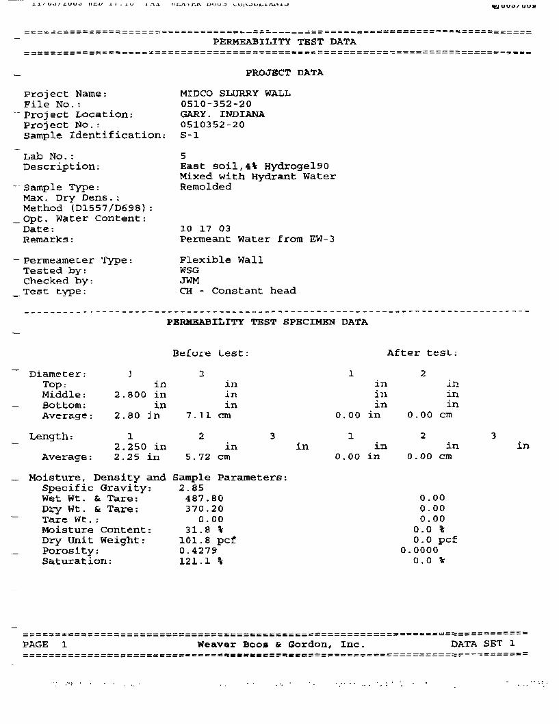
T1£,.-\*C.I\ DI'UO
PERMEABILITY TEST DATA
PROJECT DATA
Project Name:File No.:Project Location:Project No.:Sample Identification:
Lab No.:Description:
Sample Type:Max. Dry Dens.:Method (D1557/D698):Opt, Water Content:Date:Remarks:
MIDCO SLURRY WALL0510-352-20GARY. INDIANA0510352-20S-l
East soil,4% Hydrogel90Mixed with Hydrant WaterRemolded
10 17 03Permeant Water from EW-3
Permeamecer Type :Tested by:Checked by:Test type :
Diameter: JTop : inMiddle: 2.800 inBottom: inAverage: 2.80 Jn
Length : i2.250 in
Average : 2.25 iri
Moisture, Density andSpecific Gravity:Wet Wt. & Tare:Dry Wt. & Tare:Tare Wt . :Moisture Content:Dry Unit Weight:Porosity:Saturation:
Flexible WallWSGJWMCH - Constant head
PERMEABILITY TEST SPECIMEN DATA
Before Lest: After tesL:
2 1 2in in inin in inin in in
7.11 cm 0.00 in 0 . 00 cm
2 3 1 2 3in in in in in
5.72 cm 0.00 in 0.00 cm
Sample Parameters:2.85487.80 0.00370.20 0-000.00 0.00
31.8 % 0.0 %101.8 pcf 0.0 pcf0.4279 0.0000121.1 % 0.0 %
PAGE 1 Weaver Boos ft Gordon, Inc. DATA SET 1

»>£.!/ .L f . J_ U
CONSTANT HEAD PERMEABILITY TEST CONDITIONS DATA
Cell No. : 5
T?\jn Number:
CASED XS R
Pane1 No.:
1
Positions
2
Cell Pressure:Saturation Pressure:Inflow Corr. Factor:Outflow Corr. Factor:Test Temperature :
24.0 psi24-0 psi1.001.0022.0 °C
0 . 0 psi0.0 psi1.001.000.0 °C
PBRMBABILITY TEST READINGS DATA
DATE TIME(24 hr)
ELAPSEDTIME-sec
GAUGEPRESSURE-psiIN OUT
BURETREADING -CCIN OUT
10/25/ .3 12:56:0010/26/ 3 12:42:0010/27/ 3 9:01:0010/27/ 3 13:04:0010/28/ 3 9:12:00
085,560158, 700173,280245,760
20.020.020.020.020.0
18.018.018.018.018.0
3 .304 .205.005.206.70
73.6072.7071.8071.6069.80
OUTFLOW/INFLOWRATIO
0.00'.I .001.131. 001.20
Test Pressure - 20.0 psi Differential Head = 2.6 psi, 181.4 cm H2OGradient = 3.173E 0.1 Flow rate - 1.401E-05 cc/sec R squared = 0.95417Permeability, K22.00 = 1.111E-08 cm/sec, K20° = 1.059E-08 cm/sec
PAGE Weaver Boos & Gordon, Inc. DATA SET 1

ntu i / : ID r/YA nr.Att.i\ DUU.S i uu / /uuy
II- SI UATA:
PERMEABILITY I EST REPORT•;:AMPI r DAI A .
Specimen H^ighi ( , <m) . l r > . / 2 Stamp !<• Trlfint i T i ca t i on : 5-^1'ipcc i men D i oniis I - 1 (. cm ) . / . 1Dry Ur> i1 Wo i <jh 1 ( pC f 1 1 9« . l? V isual D e s c r i p t i o n : N-5-W 5Oi .-1^. SW I <"l IMo is ture Gc^forc T«st ( X ) : 42 9 M v eel v / i l h llyjront Wate rMo i •» lur *; A f l c r Ttst (Sj : U.G Remarks' Peimeorir v»otor f r om MWi;,DRun Nurnder: • 2 *C« I I Pressure (ps i ' ) : 2-1.0 Ma-.imum Dry Densi ty ( .pcf ) :Teal Pressurc(ps I ) : 20.0 Opt imum Mois lure Content (%) :Qack Pr«ssurc(ps i ) ; 17 .4D i f f . Mead (.psi): 2.6 lj«rc«nt Compaction:Plow Rate ( cc/sec ) ; 7. .3.1 . IO--R I'errrieame t er lyp«: i - l e x i b i e Wai iPerm, (cm/s-f-o) • s n* » m--i Sample l.yp*<" Remo ded
TIMt - t i serO :OOOxOO 200 DOO
j 1D
•>T5
. :?LJ5=3
]>
O_lU. 4
ijj I v 10- 8l/)•^ 8 - 10--0eI'i, 6 , IO- -9
_!.
| 4 > 10 -»
f
n
g 2 n 10*-9
<U3cc1111- 1 x 10' -8
0
"~- ----,. • — .
•...
*'"-*
1 —
i
-••*. ,t
-
'---. ••-^._
)
-•
JiUOOOO 4.0000'?'
I1
j
:
-
j
i
-- <
10 20 30 4OAVFRAC. IIYOKAULIC- GRADIENT - dH/L (cm/cm)
Proj«st.L: MIDCO SLURRY" WALLLoc-.it inn : GAUY . LNUJ-AMA
D<3l-r;: 1O-17-O3
PERMEABILITV TEST RFPOPT
Weaver Boos A: Gordon, Jnc .
ProJHt. t Mo.: Ori1O_St>:i-20
Pi l-s l-lo. : OSlO-.T^-lC
lot) Mo . : G
Ttat*d by; w!^C
Chocked by : JWM
lest : CH •• Constant hetid
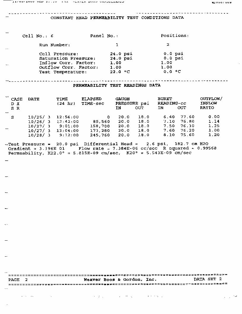
«KJ u v o / uu t»
CONSTANT HEAD PERMEABILITY TEST CONDITIONS DATA
Cell No.: 6
Run Number:
Panel No.:
1
Cell Pressure:Saturation Pressure:Inflow Corr. Factor:Colt flow Corr. Factor:Test Temperature:
24.0 psi24.0 psi1.001.0022.0 °C
Positions
2
o.o psi0.0 psi
1.001.000.0 CC
PERMEABILITY TEST READINGS DATA
CASED XS R
DATE
10/25/ 310/26/ 310/27/ 310/27/ 310/28/ .3
TIME(24 hr)
12:56:0012:42:009:01:0013: 04:009:12:00
ELAPSEDTlME-sec
085,560158,700173,280245,760
GAUGEPRESSURE psiIN OUT
20.020.020.020.020.0
18.018.018.018 .018 .0
BURETREADING-ccIN OUT
6.407.107.507.608.10
77.6076 -8076.3076 .2075.60
OUTFLOW/INFLOWRATIO
0.001.141.251.001.20
-Test Pressure = 20.0 psi Differential Head = 2.6 psi, 182.7 cm H2OGradient = 3..196E 01 Flow rate - 7.384E-06 cc/scc R squared - 0.99568Permeability, K22.00 = 5-815E-09 era/sec, K20° = 5.543E-09 cm/sec
PAGE Weaver Boos & Gordon, Inc. DATA SET 2
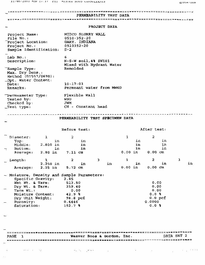
J. l / uo/*:uud
PERMEABILITY TEST DATA
PROJECT DATA
Proj ect Name:_File No.:Project Location:Project No.rSample identification:
Lab No.:Description:
""Sample TyPe:Max. Dry Dens.:Method (1)1557/0698) :
_Dpt. water Content:Date:Remarks:
Permeameter Type:Tested by:Checked by:
__Test type:
MIDCO SLURRY WALL0510-352-20GARY. INDIANA0510352-20S-2
N-S-W soil,4% SW101Mixed with Hydrant WaterRemolded
10-17-03Permeant water from MW6D
Flexible WallWSC3JWMCH - Constant head
PERMEABILITY TEST SPECIMEN DATA
Before test: After test:
Di ameter:Top:Middle:Bottom:Average:
Length:
Average:
in2.800 in
in2.80 in
2.250 in2.25 in
iriinin
7.11 cm
in5.72 cm
in
1X1
inin
0.00 in
in0.00 in
— Moisture, Density and Sample Parameters:Specific Gravity:Wet Wt. & Tare:Dry Wt. & Tare:Tare Wt.:Moisture Content:Dry Unit Weight:Porosity:Saturation:
2.85513.50359.40
0.0042.9 %98.8 pcf0.4446152.7 %
ininin
0.00 cm
in0.00 cm
0.000.000.000.0 %0.0 pcf
0-00000.0 %
in
PAGE Weaver Boos fc Gordon, Inc. DATA SET 2

naK*
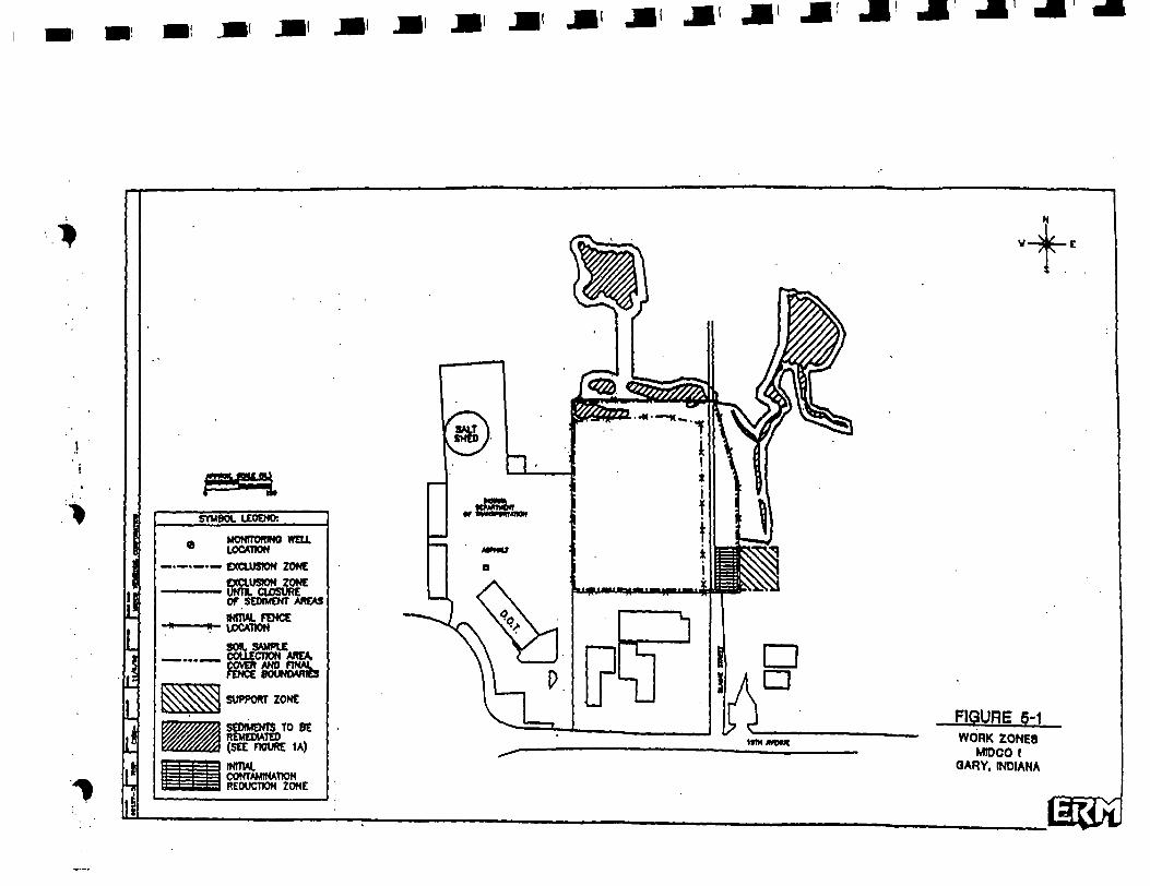
SYMBOL UPEND:
A MONITDRINO WELL9 LOCATION
_ _._ EXCLUSION ZONE
SUPPORT ZONE
SEDIMENTS TO BEREMEDIATED(SEE FIGURE 1A)
INITW.CONTAMINATIONREDUCTION ZONE
ttmwowt
FIGURE S-1WORK ZONES
MtDCO IGARY, INDIANA


CONTRACT DEWATERING SERVICES INC.
WORK PLAN FOR THE CONSTRUCTIONOF A CONTAINMENT BARRIER WALL AT THE
MIDCO I SITE LOCATED AT7400 WEST 15th AVENUE, GARY, INDIANA
MOBILIZATION
Deliver to the site the required materials and equipment to successfully construct thecontainment barrier wall in accordance with our containment barrier wall (CBW) mixdesign and the project specifications.
This includes but is not limited to the following:
Delivery of deep trencher and excavator for CBW excavation• Delivery and set up of a water supply line to assist in CBW slurry mixing
Delivery and staging of dry bentonite in 2800 Ib. super sacks for dry mixing in thebarrier wall trenchDelivery of support equipment for site prep, assistance in CBW construction andfinal clean upIdentifying the locations of any existing site utilities
SET UP WATER SUPPLY
• Lay out water line from water supply to CBW trench. Fuse together HOPE water supply line
Install necessary fittings for water controlUtilize water meter provided by the water utility for metering of water quantityused
LAYOUT BARRIER WALL LOCATION
• Layout the CBW alignment by surveying techniques in accordance with thecontract documentsLocate and reveal any utilities or other lines near the CBW alignment so they willnot be damaged by the trencher and they can be placed or rerouted out of the wayof the CBW alignment in a controlled manner
• Expose the location of the existing extraction well lines to verify the exactlocation. If the extraction lines interfere with the alignment of the barrier wall, thebarrier wall will need to be relocated as directed by ENVIRON.
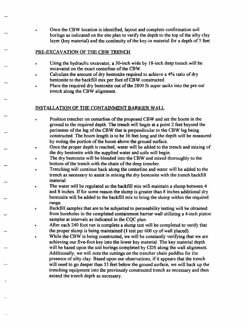
. Once the CBW location is identified, layout and complete confirmation soilborings as indicated on the site plan to verify the depth to the top of the silty claylayer (key material) and the continuity of the key-in material for a depth of 5 feet.
PRE-EXCAVATION OF THE CBW TRENCH
. Using the hydraulic excavator, a 30-inch wide by 18-inch deep trench will beexcavated on the exact centerline of the CBW.
• Calculate the amount of dry bentonite required to achieve a 4% ratio of drybentonite to the backfill mix per foot of CBW constructed.Place the required dry bentonite out of the 2800 Ib super sacks into the pre-cuttrench along the CBW alignment.
INSTALLATION OF THE CONTAINMENT BARRIER WALL
Position trencher on centerline of the proposed CBW and set the boom in theground to the required depth. The trench will begin at a point 2 feet beyond theperimeter of the leg of the CBW that is perpendicular to the CBW leg beingconstructed. The boom length is to be 36 feet long and the depth will be measuredby noting the portion of the boom above the ground surface.Once the proper depth is reached, water will be added to the trench and mixing ofthe dry bentonite with the supplied water and soils will begin.The dry bentonite will be blended into the CBW and mixed thoroughly to thebottom of the trench with the chain of the deep trencher.Trenching will continue back along the centerline and water will be added to thetrench as necessary to assist in mixing the dry bentonite with the trench backfillmaterial.
• The water will be regulated so the backfill mix will maintain a slump between 4and 8 inches. If for some reason the slump is greater than 8 inches additional drybentonite will be added to the backfill mix to bring the slump within the requiredrange.Backfill samples that are to be subjected to permeability testing will be obtainedfrom boreholes in the completed containment barrier wall utilizing a 4-inch pistonsampler at intervals as indicated in the CQC plan.After each 240 foot run is complete a slump test will be completed to verify thatthe proper slump is being maintained (1 test per 600 cy of wall placed).
• While the CBW is being constructed, we will be constantly verifying that we areachieving our five-foot key into the lower key material. The key material depthwill be based upon the soil borings completed by CDS along the wall alignment.Additionally, we will note the cuttings on the trencher chain paddles for thepresence of silty clay. Based upon our observations, if it appears that the trenchwill need to go deeper than 33 feet below the ground surface, we will back up thetrenching equipment into the previously constructed trench as necessary and thenextend the trench depth as necessary.

Once we have gone through the first 100 feet and the mix percentages have beenestablished, we will continue to install the CBW until the containment area hasbeen completed.At the location where the extraction well lines cross the CBW alignment, the lineswill be shut off, disconnected and the CBW trench continued beyond theextraction line alignment. Once the trench is completed in this area, the extractionHDPE lines will be reconnected utilizing electrofusion couplings and steel linesutilizing a mechanical coupler.
CLEANUP AND SITE RESTORATION
. Once the CBW construction is complete, we will finish grade over the new walland remove all required spoil materials to the on site disposal location under thetarped area as indicated on the plans.CDS will place a clay cap over the CBW capable of supporting pedestrian traffic.At the two road crossings over the CBW an engineered repair will be constructedcapable of supporting the anticipated traffic loads.Once the construction is complete, our support equipment will be disassembled,complete our final clean up and decontamination, and de-mobilize our equipmentoff site.
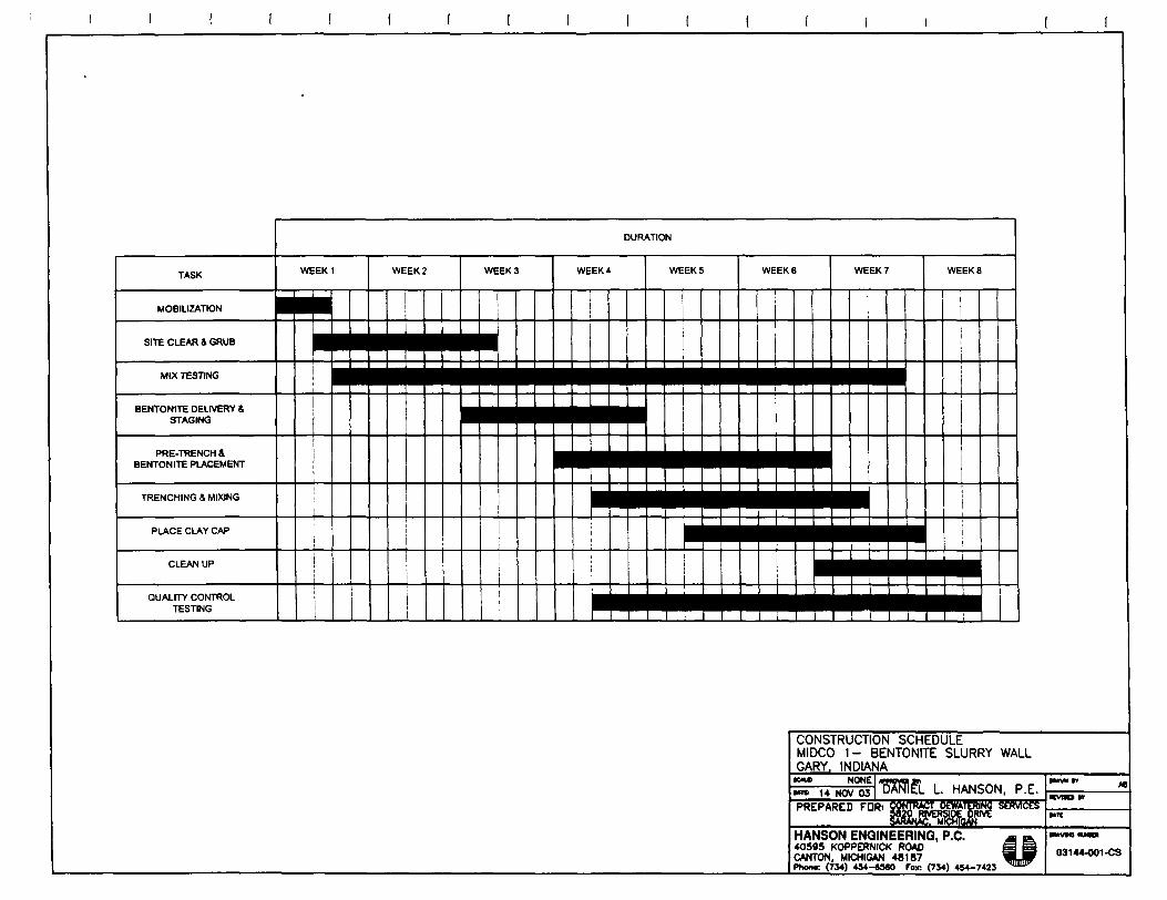
CONSTRUCTION SCHEDULEMIDCO 1- BENTONITE SLURRY WALLGARY. INDIANA
DANIEL L. HANSON, P.E.
HANSON ENGINEERING, P.C.40595 KOPPERNICK ROADCANTON, MICHIGAN 48187Phen«: <734) 454-6580 Fox; (734) 454-7423

CONTRACTDEWATERING SERVICES INC.
CONSTRUCTION QUALITY CONTROL (CQC) PLANFORMIDCOISITE
7400 WEST 15th AVENUE, GARY INDIANA
For The Installation of Containment Barrier Wall
PERSONNEL TO BE USED ON SITE:• Construction Manager• Construction Supervisor• Construction Fore man• CQC Representative• Trencher Operators. Utility Operator
Richard NeumannTony MillerTony MillerMatt BrooksDennis Karrar and Dean CalabreseTom Dykas Or Local 150 Operators
OBSERVATION AND INSPECTION
Observation and inspection of the vertical containment barrier wall (CBW) construction will beperformed by the Contract Dewatering Services Inc. CQC representative and will include thefollowing:
. Visual inspection and photo documentation of the initial clearing and grubbing, workbenchconstruction, and vertical barrier wall construction.
• Visual inspections of the lateral and vertical limits of the CBW construction.• Documentation of the trench grades. Visual classification and documentation of the key material• Obtaining samples of the soil-bentonite backfill mix for laboratory testing• Preparation of daily report documenting each days activities, locations, problems and
problem resolutions, results of tests performed and samples obtained that day and quantityof materials used.
CONSTRUCTION TESTING
Soil Borings for Confirmation of Siltv Clav Layer (Key-in Material)
. Prior to commencing installation of the CBW, 5 additional borings (indicated as CDB-5 toCDB-9 on Site Plan) are to be completed to verify the depth to the top of the silty clay layer(key material) and the key material layer continuity for at least 5 feet below the interfacewith granular materials.
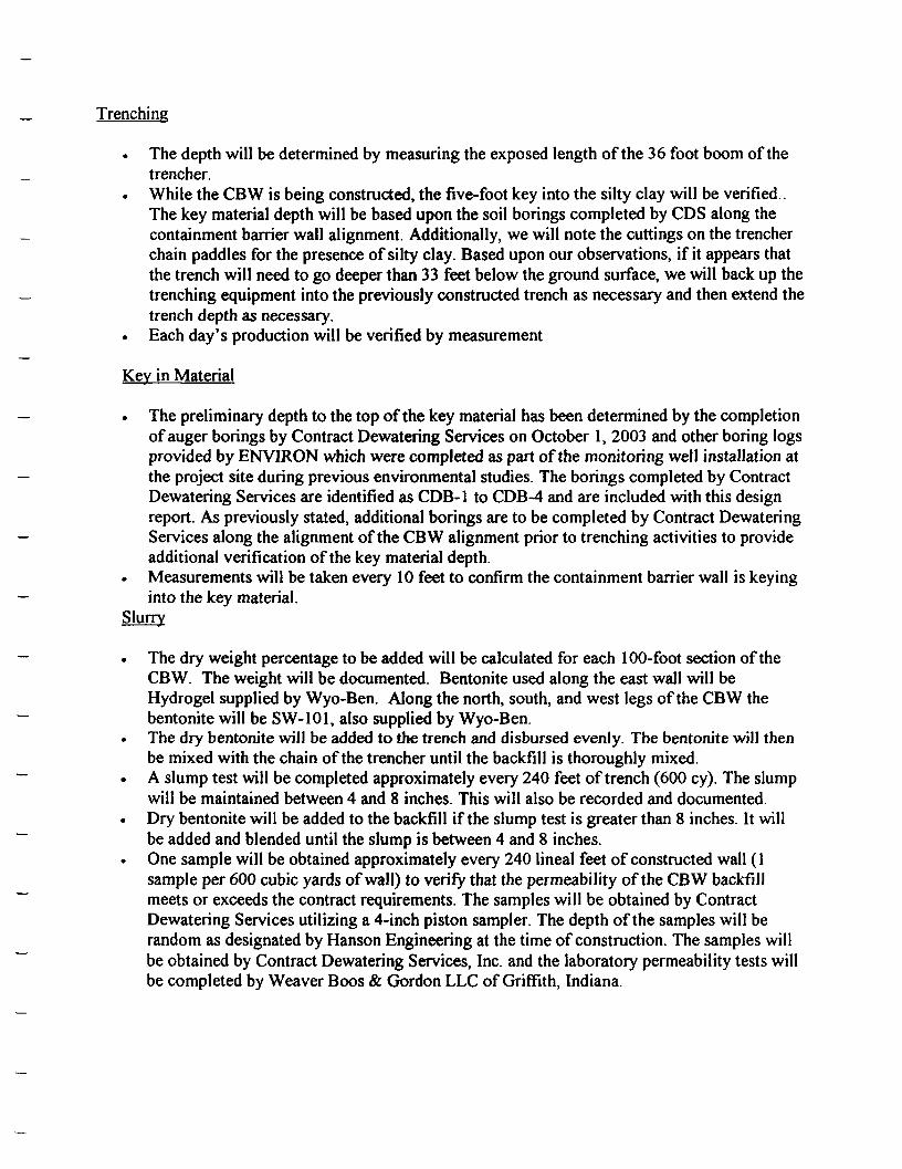
Trenching
• The depth will be determined by measuring the exposed length of the 36 foot boom of thetrencher.
• While the CBW is being constructed, the five-foot key into the silty clay will be verified..The key material depth will be based upon the soil borings completed by CDS along thecontainment barrier wall alignment. Additionally, we will note the cuttings on the trencherchain paddles for the presence of silty clay. Based upon our observations, if it appears thatthe trench will need to go deeper than 33 feet below the ground surface, we will back up thetrenching equipment into the previously constructed trench as necessary and then extend thetrench depth as necessary.
. Each day's production will be verified by measurement
Key in Material
The preliminary depth to the top of the key material has been determined by the completionof auger borings by Contract Dewatering Services on October 1, 2003 and other boring logsprovided by ENVIRON which were completed as part of the monitoring well installation atthe project site during previous environmental studies. The borings completed by ContractDewatering Services are identified as CDB-1 to CDB-4 and are included with this designreport. As previously stated, additional borings are to be completed by Contract DewateringServices along the alignment of the CBW alignment prior to trenching activities to provideadditional verification of the key material depth.
. Measurements will be taken every 10 feet to confirm the containment barrier wall is keyinginto the key material.
Slurry
. The dry weight percentage to be added will be calculated for each 100-foot section of theCBW. The weight will be documented. Bentonite used along the east wall will beHydrogel supplied by Wyo-Ben. Along the north, south, and west legs of the CBW thebentonite will be SW-101, also supplied by Wyo-Ben.
. The dry bentonite will be added to the trench and disbursed evenly. The bentonite will thenbe mixed with the chain of the trencher until the backfill is thoroughly mixed.
• A slump test will be completed approximately every 240 feet of trench (600 cy). The slumpwill be maintained between 4 and 8 inches. This will also be recorded and documented.
• Dry bentonite will be added to the backfill if the slump test is greater than 8 inches. It willbe added and blended until the slump is between 4 and 8 inches.One sample will be obtained approximately every 240 lineal feet of constructed wall (1sample per 600 cubic yards of wall) to verify that the permeability of the CBW backfillmeets or exceeds the contract requirements. The samples will be obtained by ContractDewatering Services utilizing a 4-inch piston sampler. The depth of the samples will berandom as designated by Hanson Engineering at the time of construction. The samples willbe obtained by Contract Dewatering Services, Inc. and the laboratory permeability tests willbe completed by Weaver Boos & Gordon LLC of Griffith, Indiana.

CONSTRUCTION DOCUMENTATION
All the daily QC reporting and measurements will be recorded in the final constructiondocumentation. Digital and/or 35 mm photos will be furnished and labeled to identify all majoraspects of the work.
A set of 22 by 34 inch as built drawings will be furnished showing all final alignment and details
EVALUATION OF PROJECT COC WITH INDUSTRY ACCEPTABLE STANDARDS
The following pages compares the project CQC plan with the acceptable industry standards asidentified in "Evaluation of Subsurface Engineered Barriers at Waste Sites" EPA 542-R-98-005August 1998.

MATRIX FOR EVALUATING BARRIER CQA/CQC AGAINST ACCEPTABLE INDUSTRY PRACTICES '(footnotes are indicated on page 2)
CategorySpecialty Contractor Experience
Trench Excavation Methods
Trench Width, Verticality & Continuity
Trench Sounding (slope and bottom)
Trench Bottom CleaningTrench Key Confirmation
Slurry MixingSlurry Viscosity Testing
Slurry Viscosity
Slurry Sand Content tests
Slurry Sand Content
Backfill Slump TestingBackfill Slump
Backfill Gradation TestingBackfill Permeability testing
Backfill Target Permeability
Backfill Mixing/Placement
Capping Confirmation
Barrier ContinuityPost Construction BarrierSampling/TestingAs-Built recordsGroundwater Head Monitoring
Final Barrier Alignment Survey
Barrier Construction SpecificationCQA/CQC Program and Testing Spec.Groundwater Chemistry and Monitoring
Less than Acceptable<4
No Inspection
No Inspection
>20ft
NoneNo Sampling
<
<2
<40
<2
>15%<
<3"or>6"<1<1>
Loosely Controlled
None
Interrupted
None
None
None
NoneNone
NoneNone
Acceptable4-6 Comparable Projects
Periodic Inspections
Periodic Inspection
Per 10-20 ft
YesSampling Every 20 feet
Agitation > 12 hrs. Hydration2 per shift
40+ seconds
2 per shift
<15%1 per 400-600cy
Most Tests 3"-6"1 per 400-600cy
1 per 400-600cy
5xlQ- 7 - lx lO- 7 cm/sec
Controlled Mix/Place
Cap Confirmed
Continuous
Minimal
Construction Completion Report
Monitored Fluctuation
SurveyedBarrier
Designer SpecifiedMinimal
Better than Acceptable>6
Constant Inspection
Measured
<10ft.
>
Sampling < 20 ft.>
>2
40-50 Seconds
>2
«15%>
All Tests 3"-6"
>1
>1<
Central Mix/GuidedPlacement
>
Continuous & Confirmed
Regular & Documented
Report Drawings, Test Results
Periodic & Across Barrier
Surveyed & MonumentedBarrier & CQA Plan
Independent Duplicated QA
Periodic & Across Barrier
Provided at Midco I Site>6
Constant Inspection
Equipment is set to maintainContinuous by observation of
equipment boom markingsN.A.2
See footnote 3
N.A.2
N.A.2
N.A.2
N.A.2
N.A.2
1 per 600 cy
All tests 4" -8""
N.A.5
1 per 600 cy
IxlO'7 cm/sec6
Guided Placement
Cap Confirmed
Continuous and Confirmed
Regular and Documented
Report Drawings, Test Results
N.A.
Provided with As-builtsBarrier & CQC Plan
Hanson Engineering DesignN.A.

FOOTNOTES TO MATRIX FOR EVALUATING BARRIER CQA/CQC AGAINST ACCEPTABLE INDUSTRY STANDARDS
1. Table 3-4 from "Evaluation of Subsurface Engineered Barriers at Waste Sites" EPA 542-R-98-005 August 19982. These categories apply only to slurry trench walls constructed by excavating a trench, filled with bentonite slurry to support the trench and
then backfilled with a mixture of low permeability fill. The method used for this project will consist of mixing the bentonite in-place withthe existing soil without any excavation.
3. While the barrier wall is being constructed, we will be constantly verifying that we are achieving our five-foot key into the lower keymaterial. The key material depth will be based upon the soil borings completed by CDS along the wall alignment. Additionally, we will notethe cuttings on the trencher chain paddles for the presence of clay. Based upon our observations, if it appears that the trench will need to godeeper than 33 feet below the ground surface, we will back up the trenching equipment into the previously constructed trench as necessaryand then extend the trench depth as necessary.
4. For the method of mixed in place soil-bentonite slurry wall that is being used on this project this slump range is acceptable since the risk ofmaterial segregation does not exist. Material segregation can occur in conventional slurry wall construction as the trench is backfilled.
5. Since the soil-bentonite slurry is thoroughly mixed in the excavated trench and not on the surface as in conventional slurry wall constructionthis testing is not necessary.
6. Minimum value as indicated in the request for bid proposal

M
ca

MATRIX FOR EVALUATING BARRIER CQA/CQC AGAINST ACCEPTABLE INDUSTRY PRACTICES '(footnotes are indicated on page 2)
CategorySpecialty Contractor Experience
Trench Excavation MethodsTrench Width, Verticality & Continuity
Trench Sounding (slope and bottom)
Trench Bottom CleaningTrench Key Confirmation
Slurry MixingSlurry Viscosity TestingSlurry ViscositySlurry Sand Content tests
Slurry Sand ContentBackfill Slump TestingBackfill SlumpBackfill Gradation TestingBackfill Permeability testing
Backfill Target Permeability
Backfill Mixing/Placement
Capping Confirmation
Barrier ContinuityPost Construction BarrierSampling/TestingAs-Built records
Groundwater Head MonitoringFinal Barrier Alignment Survey
Barrier Construction SpecificationCQA/CQC Program and Testing Spec.Groundwater Chemistry and Monitoring
Less than Acceptable<4
No InspectionNo Inspection
>20ft
NoneNo Sampling
<
<2<40<2
>15%<
<3"or>6"<1<1>
Loosely Controlled
NoneInterrupted
None
None
None
NoneNoneNoneNone
Acceptable4-6 Comparable Projects
Periodic InspectionsPeriodic Inspection
Per 10-20 ft
YesSampling Every 20 feet
Agitation > 12 hrs. Hydration2 per shift
40+ seconds2 per shift
<15%1 per 400-600cy
Most Tests 3"-6"1 per 400-600cy1 per 400-600cy
5xlO-7- lxlQ-7 cm/sec
Controlled Mix/Place
Cap Confirmed
Continuous
Minimal
Construction Completion ReportMonitored Fluctuation
SurveyedBarrier
Designer SpecifiedMinimal
Better than Acceptable>6
Constant InspectionMeasured
<10ft.
>
Sampling < 20 ft.>
>240-50 Seconds
>2«15%
>
All Tests 3"-6">1>1<
Central Mix/GuidedPlacement
>
Continuous & Confirmed
Regular & Documented
Report Drawings, Test Results
Periodic & Across Barrier
Surveyed & MonumentedBarrier & CQA Plan
Independent Duplicated QAPeriodic & Across Barrier
Provided at Midco I Site>6
Constant Inspection
Equipment is set to maintainContinuous by observation of
equipment boom markingsN.A.2
See footnote 3
N.A.2
N.A.2
N.A. 2
N.A.2
N.A.2
1 per 600 cyAll tests 4" -8""
N.A.5
1 per 600 cylx!0-? cm/sec6
Guided Placement
Cap ConfirmedContinuous and Confirmed
Regular and Documented
Report Drawings, Test Results
N.A.Provided with As-builts
Barrier & CQC PlanHanson Engineering Design
N.A.

FOOTNOTES TO MATRIX FOR EVALUATING BARRIER CQA/CQC AGAINST ACCEPTABLE INDUSTRY STANDARDS
1. Table 3-4 from "Evaluation of Subsurface Engineered Barriers at Waste Sites" EPA 542-R-98-005 August 19982. These categories apply only to slurry trench walls constructed by excavating a trench, filled with bentonite slurry to support the trench and
then backfilled with a mixture of low permeability fill. The method used for this project will consist of mixing the bentonite in-place with theexisting soil without any excavation.
3. While the barrier wall is being constructed, we will be constantly verifying that we are achieving our five-foot key into the lower keymaterial. The key material depth will be based upon the soil borings completed by CDS along the wall alignment. Additionally, we will notethe cuttings on the trencher chain paddles for the presence of clay. Based upon our observations, if it appears that the trench will need to godeeper than 33 feet below the ground surface, we will back up the trenching equipment into the previously constructed trench as necessaryand then extend the trench depth as necessary.
4. For the method of mixed in place soil-bentonite slurry wall that is being used on this project this slump range is acceptable since the risk ofmaterial segregation does not exist. Material segregation can occur in conventional slurry wall construction as the trench is backfilled.
5. Since the soil-bentonite slurry is thoroughly mixed in the excavated trench and not on the surface as in conventional slurry wall constructionthis testing is not necessary.
6. Minimum value as indicated in the request for bid proposal

IIH

MIDCOICONTRACT DEWATERING
HEALTH AND SAFETY PLAN
Table of Contents
1.0 INTRODUCTION 3
1.1 Site Details 31.2 Site History 31.3 Scope of Work 41.4 Health and Safety Plan (HASP) 4
2.0 SITE PERSONNEL 5
2.1 HASP responsibilities 52.2 On-site Personnel 6
3.0 SITE ACTIVITIES 6
3.1 Task Information 63.2 Site Hazards 63.3 Potential Contaminant Media 63.4 Contaminant Evaluation 73.5 Potential Operations Hazards 10
4.0 ACCIDENT PREVENTION PROGRAM 10
4.1 General Guidelines 104.2 Miscellaneous Rules 124.3 Trenching Rules 124.4 Personal Protection Rules 124.5 Heavy Equipment Rules 13
5.0 PROJECT DESCRIPTION / TASK EVALUATION 14
5.1 Containment Barrier Wall Construction 14
6.0 SITE CONTROL 15
6.1 Engineering Controls 156.2 Administrative Controls 166.3 Personnel Protective Equipment (PPE) 17

Contract Dewatering Services, Inc. Health and Safety Plan - Midco I
6.4 Description of Levels of Protection -During All Tasks 186.5 Heat Stress Disorders-During All Tasks 196.6 Exposure to Cold -During All Tasks 20
7.0 SITE AIR MONITORING PROGRAM 21
7.1 Organic Gases and Vapors 217.2 Inorganic Gases, Vapors and Particulates 21
8.0 CONTINGENCIES 22
8.1 Emergency Contacts and Phone Numbers 228.2 Local Medical Emergency Facility 228.3 Response Plans 238.4 Decontamination Plan 24
9.0 PERSONNEL RESPONSIBILITIES AND STATUS OF CERTIFICATION ....26
9.1 Responsibilities of Foreman/Qualified Employee 269.2 Discipline Policy 27
10.0 TRAINING AND BRIEFING TOPICS 28
11.0 SUBCONTRACTOR'S HEALTH ANDSAFETY PROGRAM EVALUATION 28
APPENDICES
Appendix A - Job Hazards Analysis A-l to A-6Appendix B - HASP Review Signatures B-lAppendix C - MSDS/Chemical Data SheetsAppendix D - FIGURES
Figure 3-1 - Map from Site to Nearest Hospital (as provided in ERM Site HASP)Figure 7-2 -Hydrogen Cyanide Monitoring and Response Flow Chart (as
provided in ERM Site HASP)Appendix E - Supplemental Table from ERM Site HASP
Table 4-1 (Updated November 2003) - Exposure Limits and RecognitionQualities of Various Compounds
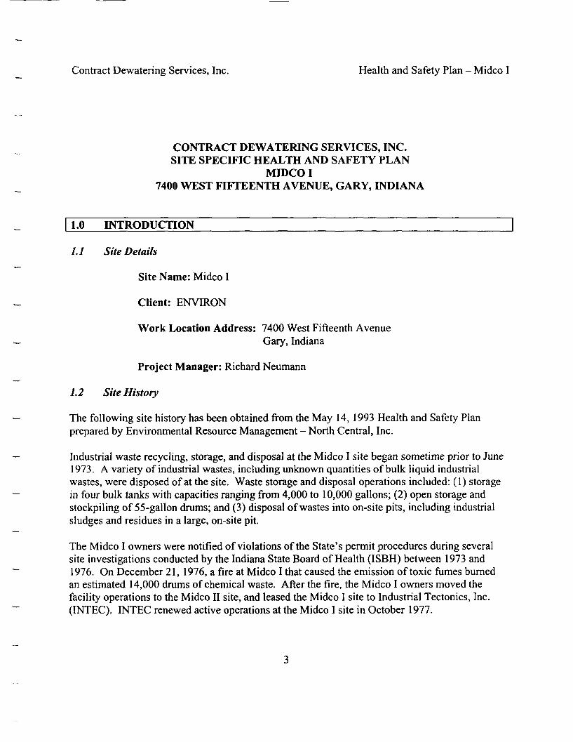
Contract Dewatering Services, Inc. Health and Safety Plan - Midco I
CONTRACT DEWATERING SERVICES, INC.SITE SPECIFIC HEALTH AND SAFETY PLAN
MIDCO I7400 WEST FIFTEENTH AVENUE, GARY, INDIANA
1.0 INTRODUCTION
/./ Site Details
Site Name: Midco I
Client: ENVIRON
Work Location Address: 7400 West Fifteenth AvenueGary, Indiana
Project Manager: Richard Neumann
1.2 Site History
The following site history has been obtained from the May 14, 1993 Health and Safety Planprepared by Environmental Resource Management - North Central, Inc.
Industrial waste recycling, storage, and disposal at the Midco I site began sometime prior to June1973. A variety of industrial wastes, including unknown quantities of bulk liquid industrialwastes, were disposed of at the site. Waste storage and disposal operations included: (1) storagein four bulk tanks with capacities ranging from 4,000 to 10,000 gallons; (2) open storage andstockpiling of 55-gallon drums; and (3) disposal of wastes into on-site pits, including industrialsludges and residues in a large, on-site pit.
The Midco I owners were notified of violations of the State's permit procedures during severalsite investigations conducted by the Indiana State Board of Health (ISBH) between 1973 and1976. On December 21, 1976, a fire at Midco I that caused the emission of toxic fumes burnedan estimated 14,000 drums of chemical waste. After the fire, the Midco I owners moved thefacility operations to the Midco II site, and leased the Midco I site to Industrial Tectonics, Inc.(INTEC). INTEC renewed active operations at the Midco I site in October 1977.

Contract Dewatering Services, Inc. Health and Safety Plan - Midco I
Fire-damaged drums of waste were still at the Midco I site in 1978. During an inspection onMarch 15, 1979, the ISBH found that INTEC had accumulated several thousand drums of waste.The State and the USEPA collected samples of soil, waste, and ponded water from the site inApril and May of 1979. The USEPA constructed a fence around the Midco I site in June 1981and retained Ecology and Environment, Inc. (E&E) to conduct a preliminary hydrogeologicalstudy of the site between June 1981 and September 1982.
On January 27, 1982, the USEPA announced a contract award for the removal of hazardouswastes from the Midco I site. During the completion of Phases 1, 2, and 3 of the waste removalActivities, the following were removed from the site: (1) approximately 14,000 burned andcrushed drums; (2) about 7,300 drums containing waste materials; (3) approximately 10,000gallons of liquid and 8,000 gallons of sludge found in two underground storage tanks; and (4) 1foot of contaminated soil. A clay cap, ranging in depth from 0 to 1 foot, was placed over thearea of the site to the west of Blaine Street. The removal activities were completed betweenFebruary 1982 and July 1982. The site was place on the National Priorities List (NPL) onSeptembers, 1983.
1.3 Scope of Work
The purpose of this project is to construct a containment barrier wall to isolate subsurfacecontamination within the limits of the containment area. Types and levels of contaminationexpected to be encountered as part of the Work is described in Table 1 of Section 3.4.
The objective of this containment barrier wall is to provide a continuous, vertical, hydrauliccutoff wall to isolate subsurface contamination within the containment area and preventmigration of contaminants outside of the on-site containment area. The containment barrier wallwill maintain a minimum hydraulic conductivity of 1 X 10 "7 cm/sec. The design of thecontainment barrier wall will account for the fact that the wall will be exposed to knowncontaminants and concentrations for an extended period of time.
1.4 Health and Safety Plan (HASP)
Contract Dewatering Services, Inc. and any subcontractors must provide trained personnel with awritten, site specific, Health and Safety Plan in order to work on this site. Personnel training andHASP requirements are set forth in 29 CFR 1910.120. No contractor or agent, employee orassignee is to work at this site unless they comply in full with the health and safety requirementsspecified in 29 CFR 1910.120. Any employee or visitor of CDS shall have a medicalsurveillance physical within the past year in accordance with 29 CFR 1910.120 before they mayenter the work area.
It is the policy of Contract Dewatering Services, Inc. to provide a safe workplace for itsemployees. To this end, the company, in concert with employees, will seek to comply with
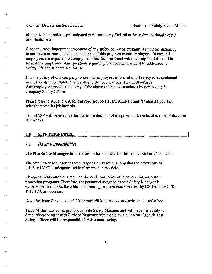
Contract Dewatering Services, Inc. Health and Safety Plan - Midco I
all applicable standards promulgated pursuant to any Federal or State Occupational Safetyand Health Act.
Since the most important component of any safety policy or program is implementation, itis our intent to communicate the contents of this program to our employees. In turn, allemployees are expected to comply with this document and will be disciplined if found tobe in non-compliance. Any questions regarding this document should be addressed toSafety Officer, Richard Neumann.
It is the policy of this company to keep its employees informed of all safety rules containedin the Construction Safety Standards and the Occupational Health Standards.Any employee may obtain a copy of the above referenced standards by contacting thecompany Safety Officer.
Please refer to Appendix A for our specific Job Hazard Analysis and familiarize yourselfwith the potential job hazards.
This HASP will be effective for the entire duration of the project. The estimated time of durationis 7 weeks.
2.0 SITE PERSONNEL
2.1 HASP Responsibilities
The Site Safety Manager for activities to be conducted at this site is: Richard Neumann.
The Site Safety Manager has total responsibility for ensuring that the provisions ofthis Site HASP is adequate and implemented in the field.
Changing field conditions may require decisions to be made concerning adequateprotection programs. Therefore, the personnel assigned as Site Safety Manager isexperienced and meets the additional training requirements specified by OSHA in 29 CFR1910.120, as necessary.
Qualifications: First aid and CPR trained, 40-hour trained and subsequent refreshers.
Tony Miller may act as provisional Site Safety Manager and will have the ability fordirect phone contact with Richard Neumann while on-site. The on-site Health andSafety officer will be responsible for site monitoring.
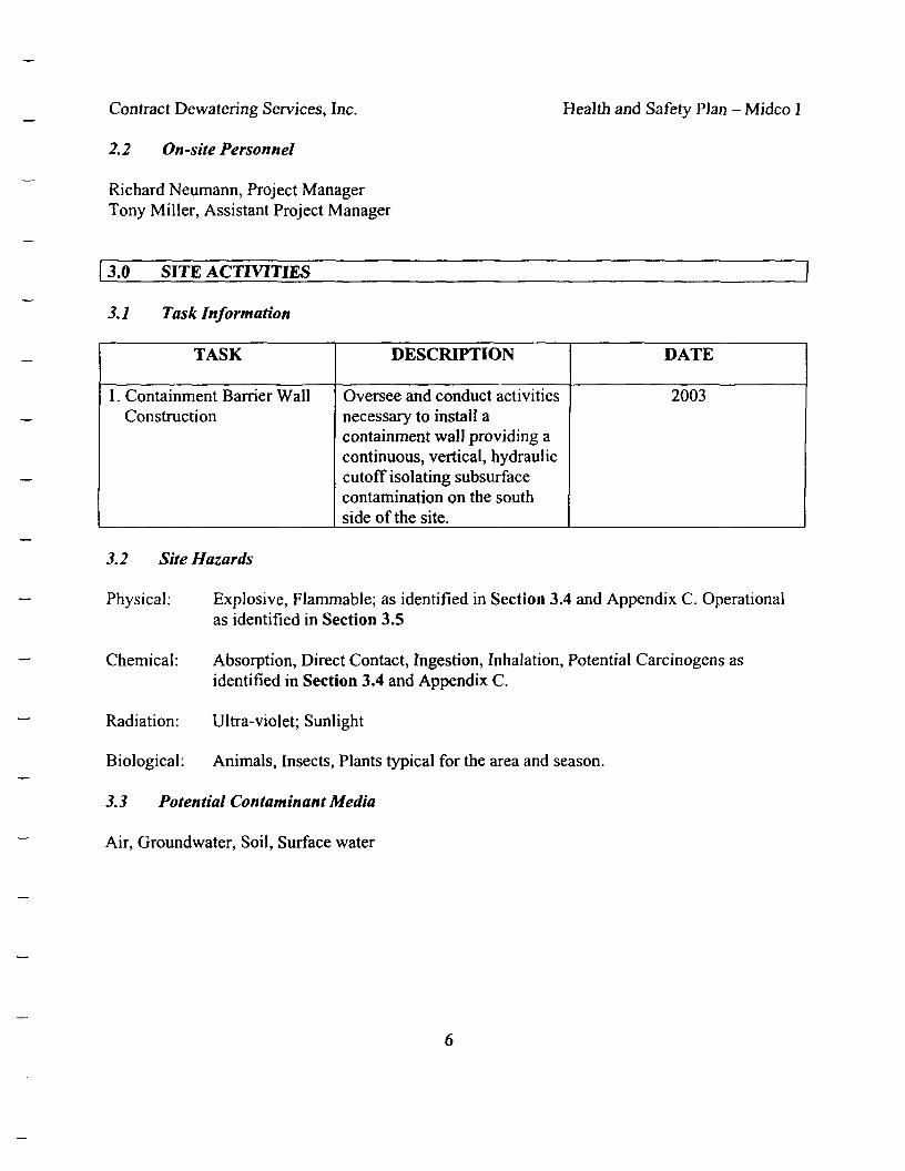
Contract Dewatering Services, Inc.
2.2 On-site Personnel
Richard Neumann, Project ManagerTony Miller, Assistant Project Manager
Health and Safety Plan - Midco I
3.0 SITE ACTIVITIES
3.1 Task Information
TASK
1 . Containment Barrier WallConstruction
DESCRIPTION
Oversee and conduct activitiesnecessary to install acontainment wall providing acontinuous, vertical, hydrauliccutoff isolating subsurfacecontamination on the southside of the site.
DATE
2003
3.2 Site Hazards
Physical: Explosive, Flammable; as identified in Section 3.4 and Appendix C. Operationalas identified in Section 3.5
Chemical: Absorption, Direct Contact, Ingestion, Inhalation, Potential Carcinogens asidentified in Section 3.4 and Appendix C.
Radiation: Ultra-violet; Sunlight
Biological: Animals, Insects, Plants typical for the area and season.
3.3 Potential Contaminant Media
Air, Groundwater, Soil, Surface water

Contract Dewatering Services, Inc.
3.4 Containment Evaluation
Health and Safety Plan - Midco I
3.4.1 The following table summarizes the approximate range of concentrations ofcompounds detected in the soil and groundwater during the remedialinvestigation.
TABLE 1
CONTAMINANT CONCENTRATIONS IN GROUNDWATER AND SOIL
CompoundsGroundwater
Units ConcentrationRange Detected
SoilConcentration
Range Detected
Water QualityAluminumAntimonyArsenicBariumBerylliumCadmiumCalciumChromiumCobaltCopperIronLeadMagnesiumManganeseMercuryNickelPotassiumSeleniumSilverSodiumThalliumTinVanadiumZincAcenaphteneAcenaphthyleneAcetoneAnthraceneBenzene
mg/1mg/1mg/1mg/1mg/1mg/1mg/1mg/1mg/1mg/1mg/1mg/1mg/1mg/1mg/1mg/1mg/1mg/1mg/1mg/1mg/1mg/1mg/1mg/1mg/1mg/1mg/1mg/1mg/1
0.027-41.3ND-0.022ND-0.066ND-11.4
NAND-0.0223.05-1270ND-5.95
ND-0.091ND-1.280.064-187ND-0.2950.182-3850.004-6.81ND-0.0015
ND-34.13.3-486ND-0.04
ND-0.04114.4-27600ND-0.05ND-1.31ND-0.15ND-3.11
NANA
ND-30ND-0.004
ND-6.8
458-31100ND-103ND-49
ND-1090ND-3.4ND-17
230-103000ND- 10200
ND-20ND-292001280-699002.4-1420
8.81-62400ND-537
ND-3ND-6620ND-5400ND-3.5ND-11
ND-20500ND-1.2ND-470ND-81
3.1-7860ND-26
NAND-480ND-210ND-14
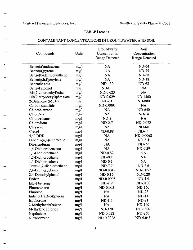
Contract Dewatering Services, Inc. Health and Safety Plan - Midco I
TABLE 1 (cont.)
CONTAMINANT CONCENTRATIONS IN GROUND WATER AND SOIL
Compounds
Benzo(a)anthraceneBenzo(a)pyreneB enzo(b&k)fiuorantheneBenzo(g,h,i)peryleneBenzoric acidBenzyl alcoholBis(2-chloroethyl)etherBis(2-ethylhexyl)phthalate2-Butanone (MEK)Carbon disulfideChlorobenzeneChlordaneChloroethaneChloroformChryseneCresol4,4'-DDDDibenzo(a,h)anthraceneDibenzofuran1 ,4-Dichlorobenzene1 , 1 -Dichloroethane1 ,2-Dichloroethane1,1-DichloroetheneTrans- 1 ,2-dichloroethene2,4-Dichlorophenol2,4-DimethylphenolEndrinEthyl benzeneFluorantheneFluoreneIndeno( 1 ,2,3-cd)pyreneIsophorone2-MethylnaphthaleneMethylene chlorideNapthaleneNitrobenzene
Units
mg/1mg/1mg/1mg/1mg/1mg/1mg/1mg/1mg/1mg/1mg/1mg/1mg/1mg/1mg/1mg/1mg/1mg/1mg/1mg/1mg/1mg/1mg/1mg/1mg/1mg/1mg/1mg/1mg/1mg/1mg/1mg/1mg/1mg/1mg/1mg/1
GroundwaterConcentration
Range Detected
NANANANA
ND-130ND-0.1
ND-0.023ND-0.029
ND-84ND-0.0091
NANA
ND-2ND-2.7
NAND-0.88
NANANANA
ND-0.82ND-0.1ND-0.1ND-7.7
ND-0.0048ND-0.1 6
ND-0.0005ND-1.9
ND-0.003NANA
ND-1.5NA
ND-320ND-0.022ND-0.0028
SoilConcentration
Range Detected
ND-64ND-29ND-68ND-18ND-68
NANA
ND-1300ND-880
NAND-640ND-14
NAND-0.022
ND-64ND-11
ND-0.0068ND-6.4ND-22
ND-0.29NANANA
ND-2.6ND-0.057ND-0.28ND-4.4
ND-3100ND-160ND-23ND-14ND-81
ND-140ND-3600ND-260
ND-0.045
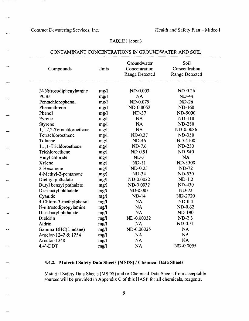
Contract Dewatering Services, Inc. Health and Safety Plan - Midco I
TABLE 1 (cont.)
CONTAMINANT CONCENTRATIONS IN GROUND WATER AND SOIL
CompoundsGroundwater
Units ConcentrationRange Detected
SoilConcentration
Range Detected
N-NitrosodiphenylaminePCBsPentachlorophenolPhenanthrenePhenolPyreneStyrene1 , 1 ,2,2-TetrachloroethaneTetrachloroetheneToluene1,1,1 -TrichloroethaneTrichloroetheneVinyl chlorideXylene2-Hexanone4-Methy 1 -2-pentanoneDiethyl phthalateButyl benzyl phthalateDi-n-octyl phthalateCyanide4-Chloro-3 -methylphenolN-nitrosodipropylamineDi-n-butyl phthalateDieldrinAldrinGamma-BHC(Lindane)Aroclor-1242& 1254Aroclor-12484,4'-DDT
mg/1mg/1mg/1mg/1mg/1mg/1mg/1mg/1mg/1mg/1mg/1mg/1mg/1mg/1mg/1mg/1mg/1mg/1mg/1mg/1mg/1mg/1mg/1mg/1mg/1mg/1mg/1mg/1mg/1
ND-0.003NA
ND-0.079ND-0.0052
ND-37NANANA
ND-0.37ND-46ND-7.6
ND-0.91ND-3ND-11
ND-0.25ND-34
ND-0.0022ND-0.0032ND-0.003
ND-14NANANA
ND-0.00032NA
ND-0.00025NANANA
ND-0.26ND-44ND-26
ND-160ND-5000ND-110ND-280
ND-0.0086ND-350
ND-4100ND-230ND-840
NAND-3500
ND-72ND-530ND-1.2ND-430ND-73
ND-2720ND-0.4ND-0.62ND-190ND-2.3
ND-0.51NANANA
ND-0.0095
3.4.2. Material Safety Data Sheets (MSDS) / Chemical Data Sheets
Material Safety Data Sheets (MSDS) and or Chemical Data Sheets from acceptablesources will be provided in Appendix C of this HASP for all chemicals, reagents,

Contract Dewatering Services, Inc. Health and Safety Plan - Midco I
solutions of identified materials that in the normal process of completing the tasks for thisproject could provide the potential for exposure. All subcontractors and any other partiesworking on this site will be informed of the presence of these substances and the locationof the appropriate MSDS or data sheets. All subcontractors will be required to provideMSDS or Chemical Data sheets for any and all hazardous materials used or stored on siteduring the performance of their contracts. That information will also be made availablefor inclusion in Appendix C of this HASP.
3.5 Potential Operational Hazards
Potential hazards are present at the job site and may vary from day to day and task to task.All site personnel will be familiar with these potential hazards and take the appropriateprecautions and any steps necessary to mitigate any potential risk from these hazards at alltimes. If a hazard arises that has not been identified in this HASP or discussed during theon-site safety briefings, the Site Safety Manager should be contacted immediately.
Potential Hazards include: Noise; Heat or Cold Stress; Slips, Trips and Falls; WorkingOver/In Water; Traffic; Heavy Equipment; Overhead Cranes/Drilling; Utilities/Electrical;High Pressure/Steam; fire and explosion/fuel and oil. The hazard analysis for each is furtherdescribed in Appendix A.
There will be no open excavations greater than 5 feet and no work will be completed fromheights which would require fall protection.
4.0 ACCIDENT PREVENTION PROGRAM
4.1 General Guidelines
1. It is the policy of Contract Dewatering Services, Inc. to furnish each employeeemployment which is free from recognized hazards that are causing or are likely to causedeath or serious physical harm to such employee.
2. Contract Dewatering Services, Inc. designated Pvichard Neumann as corporate SafetyOfficer. This person is responsible for the implementation of the Company's safetyprogram. If any employee needs to know who the Company Safety Officer is, they canfind out by asking any foreman.
3. When practical, employees of Contract Dewatering Services, Inc. will participate insafety seminars sponsored by Associated Underground Contractors, Inc. and/or otherorganizations.
4. The Safety Officer shall designate a qualified employee on each crew or project who willhave the following responsibilities:
10
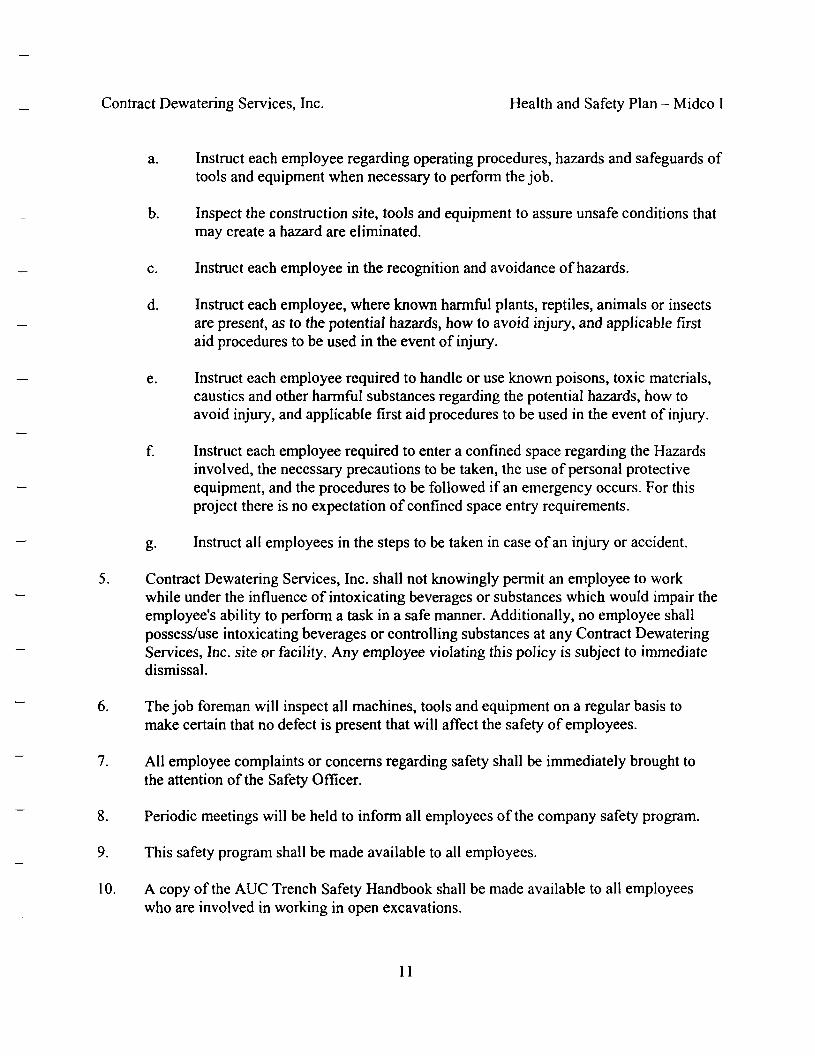
Contract Dewatering Services, Inc. Health and Safety Plan - Midco I
a. Instruct each employee regarding operating procedures, hazards and safeguards oftools and equipment when necessary to perform the job.
b. Inspect the construction site, tools and equipment to assure unsafe conditions thatmay create a hazard are eliminated.
c. Instruct each employee in the recognition and avoidance of hazards.
d. Instruct each employee, where known harmful plants, reptiles, animals or insectsare present, as to the potential hazards, how to avoid injury, and applicable firstaid procedures to be used in the event of injury.
e. Instruct each employee required to handle or use known poisons, toxic materials,caustics and other harmful substances regarding the potential hazards, how toavoid injury, and applicable first aid procedures to be used in the event of injury.
f. Instruct each employee required to enter a confined space regarding the Hazardsinvolved, the necessary precautions to be taken, the use of personal protectiveequipment, and the procedures to be followed if an emergency occurs. For thisproject there is no expectation of confined space entry requirements.
g. Instruct all employees in the steps to be taken in case of an injury or accident.
5. Contract Dewatering Services, Inc. shall not knowingly permit an employee to workwhile under the influence of intoxicating beverages or substances which would impair theemployee's ability to perform a task in a safe manner. Additionally, no employee shallpossess/use intoxicating beverages or controlling substances at any Contract DewateringServices, Inc. site or facility. Any employee violating this policy is subject to immediatedismissal.
6. The job foreman will inspect all machines, tools and equipment on a regular basis tomake certain that no defect is present that will affect the safety of employees.
7. All employee complaints or concerns regarding safety shall be immediately brought tothe attention of the Safety Officer.
8. Periodic meetings will be held to inform all employees of the company safety program.
9. This safety program shall be made available to all employees.
10. A copy of the AUC Trench Safety Handbook shall be made available to all employeeswho are involved in working in open excavations.
11
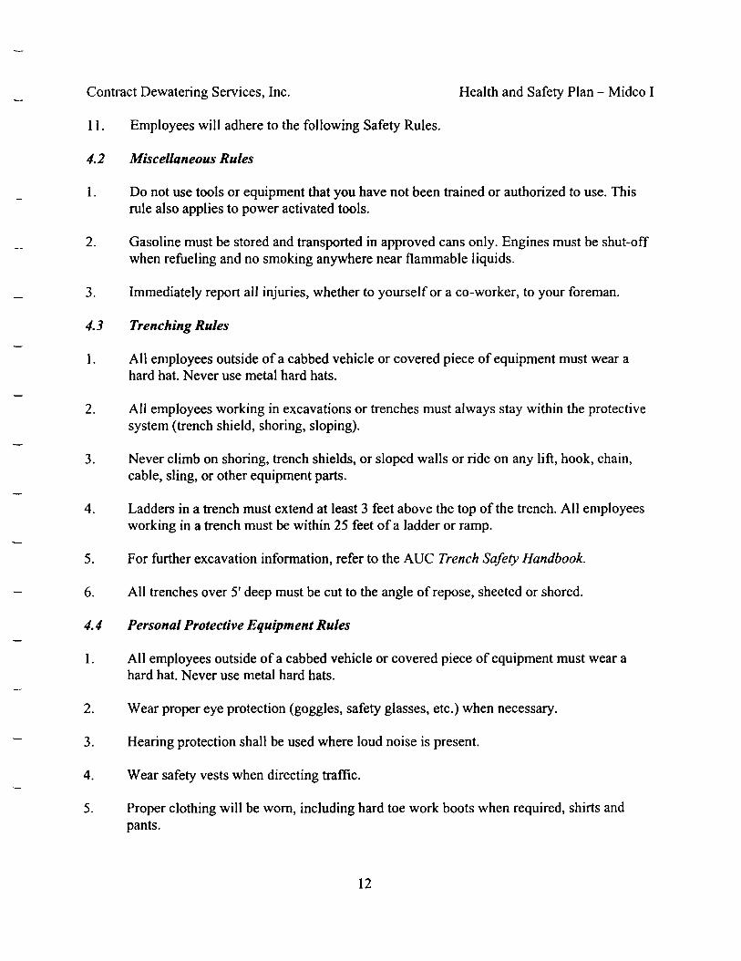
Contract Dewatering Services, Inc. Health and Safety Plan - Midco I
11. Employees will adhere to the following Safety Rules.
4.2 Miscellaneous Rules
1. Do not use tools or equipment that you have not been trained or authorized to use. Thisrule also applies to power activated tools.
2. Gasoline must be stored and transported in approved cans only. Engines must be shut-offwhen refueling and no smoking anywhere near flammable liquids.
3. Immediately report all injuries, whether to yourself or a co-worker, to your foreman.
4.3 Trenching Rules
1. All employees outside of a cabbed vehicle or covered piece of equipment must wear ahard hat. Never use metal hard hats.
2. All employees working in excavations or trenches must always stay within the protectivesystem (trench shield, shoring, sloping).
3. Never climb on shoring, trench shields, or sloped walls or ride on any lift, hook, chain,cable, sling, or other equipment parts.
4. Ladders in a trench must extend at least 3 feet above the top of the trench. All employeesworking in a trench must be within 25 feet of a ladder or ramp.
5. For further excavation information, refer to the AUC Trench Safety Handbook.
6. All trenches over 5' deep must be cut to the angle of repose, sheeted or shored.
4.4 Personal Protective Equipment Rules
1. All employees outside of a cabbed vehicle or covered piece of equipment must wear ahard hat. Never use metal hard hats.
2. Wear proper eye protection (goggles, safety glasses, etc.) when necessary.
3. Hearing protection shall be used where loud noise is present.
4. Wear safety vests when directing traffic.
5. Proper clothing will be worn, including hard toe work boots when required, shirts andpants.
12
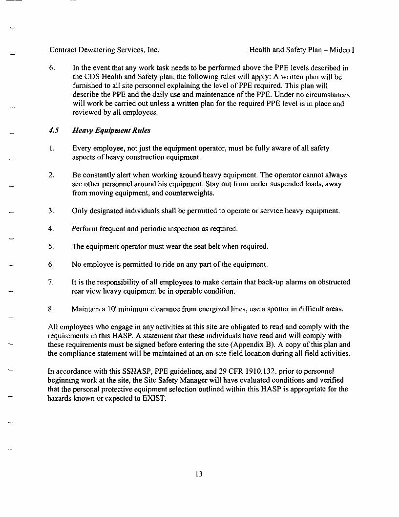
Contract Dewatering Services, Inc. Health and Safety Plan - Midco I
6. In the event that any work task needs to be performed above the PPE levels described inthe CDS Health and Safety plan, the following rules will apply: A written plan will befurnished to all site personnel explaining the level of PPE required. This plan willdescribe the PPE and the daily use and maintenance of the PPE. Under no circumstanceswill work be carried out unless a written plan for the required PPE level is in place andreviewed by all employees.
4.5 Heavy Equipment Rules
\. Every employee, not just the equipment operator, must be fully aware of all safetyaspects of heavy construction equipment.
2. Be constantly alert when working around heavy equipment. The operator cannot alwayssee other personnel around his equipment. Stay out from under suspended loads, awayfrom moving equipment, and counterweights.
3. Only designated individuals shall be permitted to operate or service heavy equipment.
4. Perform frequent and periodic inspection as required.
5. The equipment operator must wear the seat belt when required.
6. No employee is permitted to ride on any part of the equipment.
7. It is the responsibility of all employees to make certain that back-up alarms on obstructedrear view heavy equipment be in operable condition.
8. Maintain a 10' minimum clearance from energized lines, use a spotter in difficult areas.
AH employees who engage in any activities at this site are obligated to read and comply with therequirements in this HASP. A statement that these individuals have read and will comply withthese requirements must be signed before entering the site (Appendix B). A copy of this plan andthe compliance statement will be maintained at an on-site field location during all field activities.
In accordance with this SSHASP, PPE guidelines, and 29 CFR 1910.132, prior to personnelbeginning work at the site, the Site Safety Manager will have evaluated conditions and verifiedthat the personal protective equipment selection outlined within this HASP is appropriate for thehazards known or expected to EXIST.
13
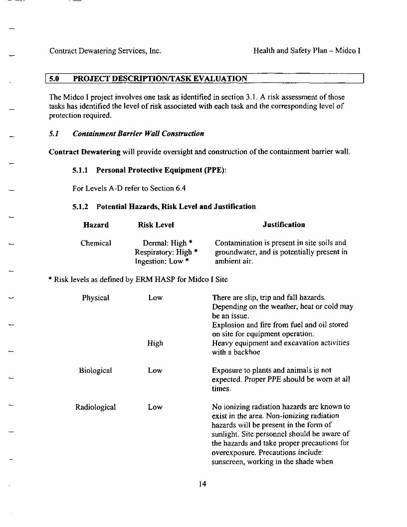
Contract Dewatering Services, Inc. Health and Safety Plan - Midco I
5.0 PROJECT DESCRIPTION/TASK EVALUATION
The Midco I project involves one task as identified in section 3.1. A risk assessment of thosetasks has identified the level of risk associated with each task and the corresponding level ofprotection required.
5.1 Containment Barrier Wall Construction
Contract Dewatering will provide oversight and construction of the containment barrier wall.
5.1.1 Personal Protective Equipment (PPE):
For Levels A-D refer to Section 6.4
5.1.2 Potential Hazards, Risk Level and Justification
Hazard Risk Level Justification
Chemical Dermal: High * Contamination is present in site soils andRespiratory: High * groundwater, and is potentially present inIngestion: Low * ambient air.
* Risk levels as defined by ERM HASP for Midco I Site
Physical Low There are slip, trip and fall hazards.Depending on the weather, heat or cold maybe an issue.Explosion and fire from fuel and oil storedon site for equipment operation.
High Heavy equipment and excavation activitieswith a backhoe
Biological Low Exposure to plants and animals is notexpected. Proper PPE should be worn at alltimes.
Radiological Low No ionizing radiation hazards are known toexist in the area. Non-ionizing radiationhazards will be present in the form ofsunlight. Site personnel should be aware ofthe hazards and take proper precautions foroverexposure. Precautions include:sunscreen, working in the shade when
14

Contract Dewatering Services, Inc. Health and Safety Plan - Midco I
possible, taking breaks in the shade, andwearing a hat for head and face protection.
5.1.3 Levels of Protection/Justification
Level D PPE will be worn for all tasks. Additional PPE may be worn to help to avoidcontact with potential biological hazards, to prevent exposure to the sun and otherweather-related hazards, and to keep workers clean. Dependent upon the data obtainedduring on-site air monitoring, higher levels of PPE (Levels C - A) may be required.
5.1.4 Safety Procedures Required and/or Field OPS Utilized
Follow applicable safety procedures outlined in this HASP and follow the buddy system.SOPs are contained in the Contract Dewatering manual and is available from the sitemanager
6.0 SITE CONTROL
6.1 Engineering Controls
For all tasks, PID and HCN monitoring should be conducted on a continuous basis. CDS Healthand Safety officer will be taking air monitoring readings every 30 minutes and recording the dataon daily reports.
The exclusion zone around the intrusion area will be identified with caution tape and a sign willbe posted at the entrance of the exclusion zone stating that no unauthorized entry is allowed.
6.1.1 On-Site Ambient Air Monitoring
1. Direct-Reading Instruments
Direct-reading instruments will be used to provide information during construction of thecontainment barrier and enable workers to make rapid decisions. During constructionactivities, VOCs and HCN will be continuously measured in the work areas at the site.Since the soil at the site will be continuously wet as a result of the construction methodused in the soil-bentonite slurry wall fugitive dust will not be created that will requiremonitoring for other constituents. Therefore, only continuous VOC and HCN monitoringwill be conducted according to the procedures described in the following paragraphs:
15
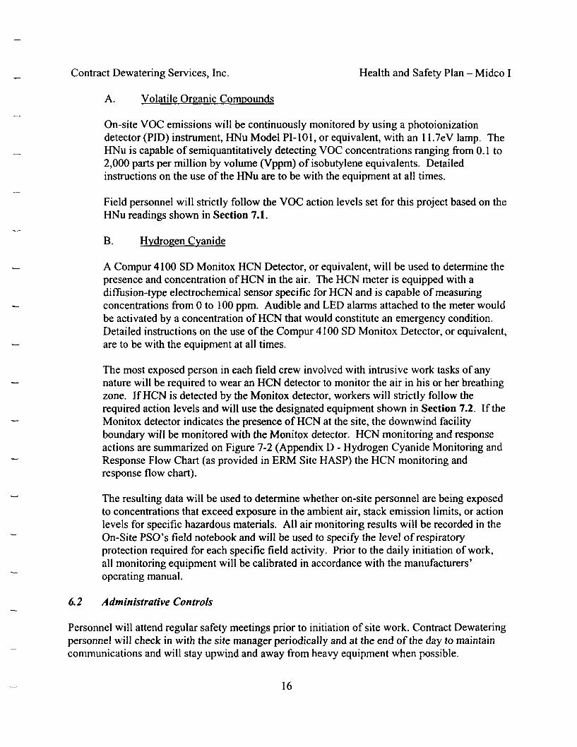
Contract Dewatering Services, Inc. Health and Safety Plan - Midco I
A. Volatile Organic Compounds
On-site VOC emissions will be continuously monitored by using a photoionizationdetector (PID) instrument, HNu Model PI-101, or equivalent, with an 11.7eV lamp. TheHNu is capable of semiquantitatively detecting VOC concentrations ranging from 0.1 to2,000 parts per million by volume (Vppm) of isoburylene equivalents. Detailedinstructions on the use of the HNu are to be with the equipment at all times.
Field personnel will strictly follow the VOC action levels set for this project based on theHNu readings shown in Section 7.1.
B. Hydrogen Cyanide
A Compur 4100 SD Monitox HCN Detector, or equivalent, will be used to determine thepresence and concentration of HCN in the air. The HCN meter is equipped with adiffusion-type electrochemical sensor specific for HCN and is capable of measuringconcentrations from 0 to 100 ppm. Audible and LED alarms attached to the meter wouldbe activated by a concentration of HCN that would constitute an emergency condition.Detailed instructions on the use of the Compur 4100 SD Monitox Detector, or equivalent,are to be with the equipment at all times.
The most exposed person in each field crew involved with intrusive work tasks of anynature will be required to wear an HCN detector to monitor the air in his or her breathingzone. If HCN is detected by the Monitox detector, workers will strictly follow therequired action levels and will use the designated equipment shown in Section 7.2. If theMonitox detector indicates the presence of HCN at the site, the downwind facilityboundary will be monitored with the Monitox detector. HCN monitoring and responseactions are summarized on Figure 7-2 (Appendix D - Hydrogen Cyanide Monitoring andResponse Flow Chart (as provided in ERM Site HASP) the HCN monitoring andresponse flow chart).
The resulting data will be used to determine whether on-site personnel are being exposedto concentrations that exceed exposure in the ambient air, stack emission limits, or actionlevels for specific hazardous materials. All air monitoring results will be recorded in theOn-Site PSO's field notebook and will be used to specify the level of respiratoryprotection required for each specific field activity. Prior to the daily initiation of work,all monitoring equipment will be calibrated in accordance with the manufacturers'operating manual.
6.2 Administrative Controls
Personnel will attend regular safety meetings prior to initiation of site work. Contract Dewateringpersonnel will check in with the site manager periodically and at the end of the day to maintaincommunications and will stay upwind and away from heavy equipment when possible.
16

Contract Dewatering Services, Inc. Health and Safety Plan - Midco I
6.2.1 Emergency Response Information
1. As part of its safety program it is the policy of Contract Dewatering to makecertain that all employees have been instructed as to proper procedures in case ofan injury or accident.
2 . Contract Dewatering designates the 911 system as its first response in the event ofa medical emergency and/or rescue operation.
3. A list of emergency phone numbers will be posted at the jobsite when practical. Ifno suitable or convenient location exists, the list will be kept by the projectforeman.
4. All injuries and/or accidents shall be reported to the job foreman immediately.
5. All accidents and/or injuries shall be reported to the Safety Officer as soon as ispractical.
6. Contract Dewatering will provide a person at each job site who is trained in CPRand First Aid procedures as required by any applicable Safety & HealthStandards.
7. Never move an injured person unless absolutely necessary. Further injury mayresult. Keep the injured comfortable and utilize available first aid equipment untilan ambulance arrives.
6.3 Personnel Protective Equipment (PPE)
63.1 Personal Protective Equipment Policy
It is the policy of Contract Dewatering that all employees comply with the IndianaOccupational Safety and Health Act (IOSHA) standards in regards to the use of personalprotective equipment. Violation of this policy will be subject to discipline as outlined inthis section.
1. This company shall provide all personal protective equipment as required inIOSHA standards.
2. All employees outside of a cabbed vehicle or a covered piece of equipment mustwear a hard hat. There will be no exceptions to this rule.
3. All employees must wear required hand protection, gloves, etc., when anemployee is exposed to hazards such as radiation, alkalies, acids, adhesives and
17

Contract Dewatering Services, Inc. Health and Safety Plan - Midco I
temperature extremes other than those caused by weather conditions. Appropriatehand protection other than ordinary work gloves will be supplied by the company.
4. Any employee directing vehicular traffic must wear a fluorescent orange vest.
5. All employees must wear proper foot protection if conditions on the job are likelyto cause foot injury. Tennis shoes or similar footwear is strictly forbidden.
6. The use of face and eye protection will vary according to the task performed. Allemployees must consult with the qualified employee to determine the propermethod of protection and this protective gear must be worn.
7. Any personal protective equipment that is found to be defective shall beimmediately reported to the safety officer or qualified person.
8. Acknowledgment of receipt of personal protective equipment will be kept on fileat the company office.
9. A company disciplinary policy is in effect regarding personal protectiveequipment and is available to all employees upon request.
6.4 Description of Levels of Protection -During All Tasks
Protection Equipment
Head: Hard Hat
Full-face air-purifyingrespirator(OSHA/NIOSH approved)
Eye and Face: Safetyglasses or goggles ifnecessaryHearing: Ear plugs ormuffs if necessary
Appropriate WorkUniform
CoverallsChemical-resistantclothing, disposable,hooded, one-or-two piecechemical splash suit
Level D
X
X
X
X
X
Level C
X
X
X
X
X
X
X
Level B
X
X
X
X
X
X
Level A
X
X
X
X
X
X
18
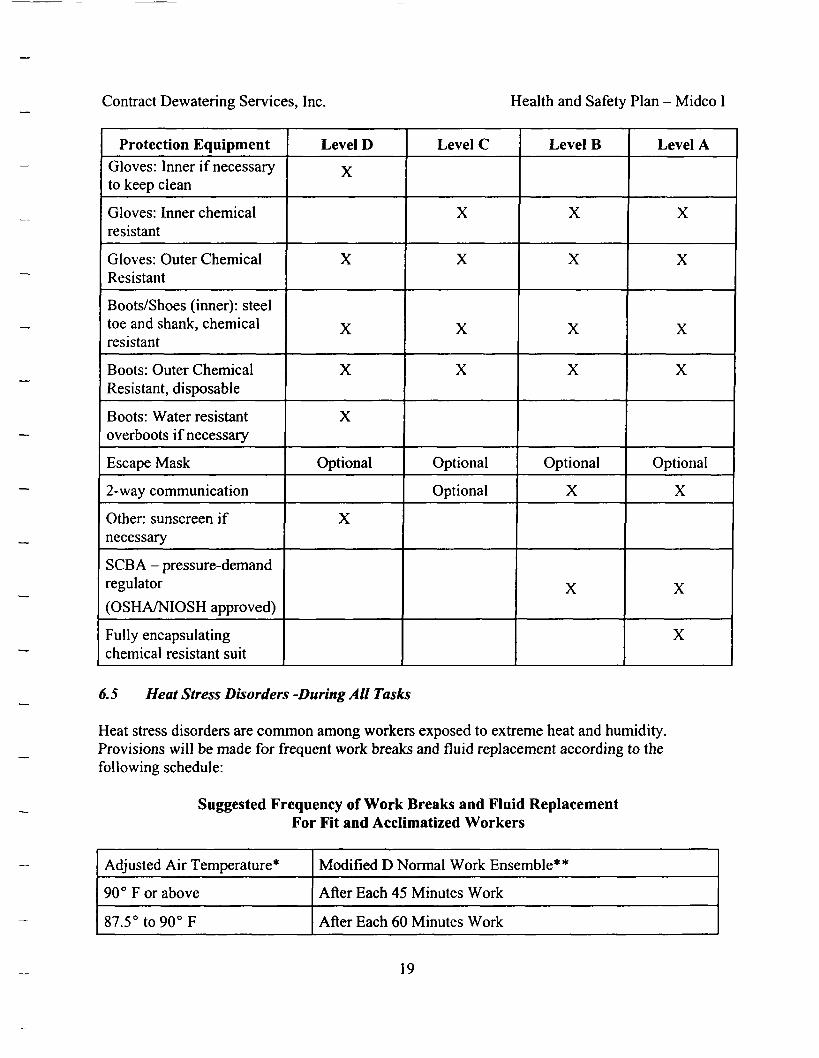
Contract Dewatering Services, Inc. Health and Safety Plan - Midco I
Protection EquipmentGloves: Inner if necessaryto keep clean
Gloves: Inner chemicalresistant
Gloves: Outer ChemicalResistant
Boots/Shoes (inner): steeltoe and shank, chemicalresistant
Boots: Outer ChemicalResistant, disposable
Boots: Water resistantoverboots if necessary
Escape Mask
2-way communication
Other: sunscreen ifnecessary
SCBA - pressure-demandregulator
(OSHA/NIOSH approved)
Fully encapsulatingchemical resistant suit
Level D
X
X
X
X
X
Optional
X
Level C
X
X
X
X
Optional
Optional
Level B
X
X
X
X
Optional
X
X
Level A
X
X
X
X
Optional
X
X
X
6.5 Heat Stress Disorders -During All Tasks
Heat stress disorders are common among workers exposed to extreme heat and humidity.Provisions will be made for frequent work breaks and fluid replacement according to thefollowing schedule:
Suggested Frequency of Work Breaks and Fluid ReplacementFor Fit and Acclimatized Workers
Adjusted Air Temperature*
90° F or above
87.5° to 90° F
Modified D Normal Work Ensemble**
After Each 45 Minutes Work
After Each 60 Minutes Work
19

Contract Dewatering Services, Inc. Health and Safety Plan - Midco I
82.5° to 87.5° F
77.5° F to 82.5° F
Below 77.5 °F
After Each 90 Minutes Work
After Each 120 Minutes Work
After Each 120 Minutes Work
**
Calculate the adjusted air temperature by using the equation for dry bulb use: AdjustedAir Temp F = Thermometer Reading F (13 X Estimated % Sunshine), % Sunshine isestimated by judging what proportion of time the sun is not covered by clouds thickenough to produce a shadow.Modified Normal Work Ensemble consists of a Tyvek Suit over lightweight cottonclothing.
Heat stress disorders can be fatal if not attended to properly. All workers on site will beinstructed in the signs and symptoms of, and First Aid for Heat Cramps, Heat Exhaustionand Heat Stroke.
6.6 Exposure to Cold -During All Tasks
Cold exposure and hypothermia are prevented or mitigated by provision of heated compartmentson heavy equipment, and heated facilities for worker breaks.
TLV's1 Work Warm Up Suggested Schedule for Four Hour Shifts
AirTemperature- Sunny Sky
Degree F(approx.)
-15to-19deg.
-20 to -24 deg.
-25 to -29 deg.
-30 to -34 deg.
-35 to -39 deg.
-40 to -44 deg.
-45 deg & below
NoNoticeableWind
Max. No. ofWork BreaksPeriod
(Norm.. Break) 1
(Norm. Break) 1
75 min 2
55 min. 3
40 min. 5
30 min 5
Non-emergencywork shouldcease
5 mphWind
Max. No. ofWork BreaksPeriod
(Norm. Break) 1
75 min 2
55 min. 3
40 min. 5
30 min 5
Non-emergencywork shouldcease
10 mphWind
Max. No. ofWork BreaksPeriod
75 min 2
55 min. 3
40 min. 5
30 min 5
Non-emergencywork shouldcease
15 mphWind
Max. No. ofWork BreaksPeriod
55 min. 3
40 min. 5
30 min 5
Non-emergencywork shouldcease
20 mphWind
Max. No. ofWork BreaksPeriod
40 min. 5
30 min 5
Non-emergencywork shouldcease
1. TLV = Threshold Limit Value
20
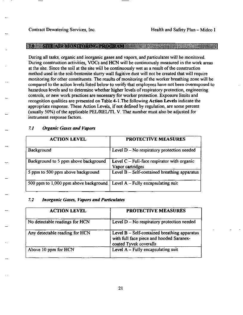
Contract Dewatering Services, Inc. Health and Safety Plan - Midco I
During all tasks, organic and inorganic gases and vapors, and particulates will be monitored.During construction activities, VOCs and HCN will be continuously measured in the work areasat the site. Since the soil at the site will be continuously wet as a result of the constructionmethod used in the soil-bentonite slurry wall fugitive dust will not be created that will requiremonitoring for other constituents. The results of monitoring of the worker breathing zone will becompared to the action levels listed below to verify that employees have not been overexposed tohazardous levels and to determine whether higher levels of respiratory protection, engineeringcontrols, or new work practices are necessary for worker protection. Exposure limits andrecognition qualities are presented on Table 4-1.The following Action Levels indicate theappropriate response. These Action Levels, if not defined by regulation, are some percent(usually 50%) of the applicable PEL/REL/TL V. That number must also be adjusted forinstrument response factors.
7. / Organic Gases and Vapors
ACTION LEVEL
Background
Background to 5 ppm above background
5 ppm to 500 ppm above background
500 ppm to 1 ,000 ppm above background
PROTECTIVE MEASURES
Level D - No respiratory protection needed
Level C - Full-face respirator with organicVapor cartridgesLevel B - Self-contained breathing apparatus
Level A - Fully encapsulating suit
7.2 Inorganic Gases, Vapors and Particulates
ACTION LEVEL
No detectable readings for HCN
Any detectable reading for HCN
Above 10 ppm for HCN
PROTECTIVE MEASURES
Level D - No respiratory protection needed
Level B - Self-contained breathing apparatuswith full face piece and hooded Saranex-coated Tyvek coverallsLevel A - Fully encapsulating suit
21
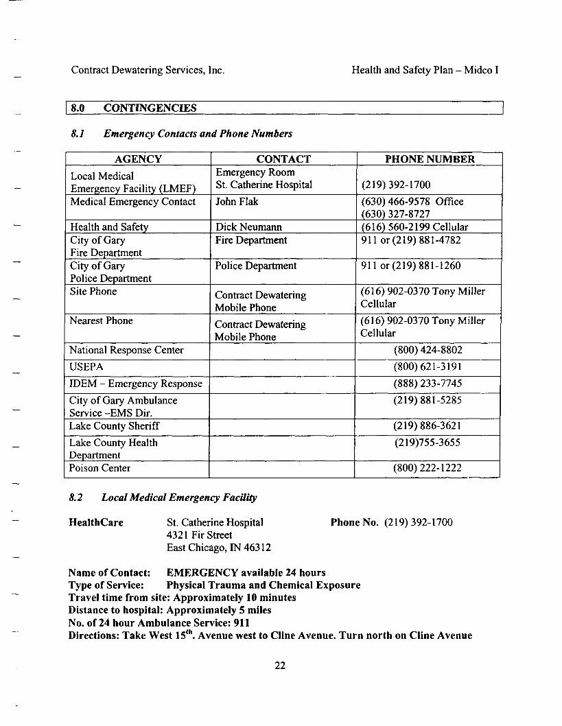
Contract Dewatering Services, Inc. Health and Safety Plan - Midco I
8.0 CONTINGENCIES
8.1 Emergency Contacts and Phone Numbers
AGENCY
Local MedicalEmergency Facility (LMEF)Medical Emergency Contact
Health and SafetyCity of GaryFire DepartmentCity of GaryPolice DepartmentSite Phone
Nearest Phone
National Response Center
USEPA
IDEM - Emergency Response
City of Gary AmbulanceService -EMS Dir.Lake County Sheriff
Lake County HealthDepartmentPoison Center
CONTACTEmergency RoomSt. Catherine Hospital
John Flak
Dick NeumannFire Department
Police Department
Contract DewateringMobile Phone
Contract DewateringMobile Phone
PHONE NUMBER
(219)392-1700
(630)466-9578 Office(630) 327-8727(616) 560-2199 Cellular91 lor (219) 881-4782
911 or (219) 881-1260
(6 16) 902-0370 Tony MillerCellular
(6 16) 902-0370 Tony MillerCellular
(800) 424-8802
(800)621-3191
(888) 233-7745
(219)881-5285
(219)886-3621
(219)755-3655
(800)222-1222
8.2 Local Medical Emergency Facility
HealthCare St. Catherine Hospital4321 Fir StreetEast Chicago, IN 46312
Phone No. (219)392-1700
Name of Contact: EMERGENCY available 24 hoursType of Service: Physical Trauma and Chemical ExposureTravel time from site: Approximately 10 minutesDistance to hospital: Approximately 5 milesNo. of 24 hour Ambulance Service: 911Directions: Take West 15th. Avenue west to Cline Avenue. Turn north on Cline Avenue
22
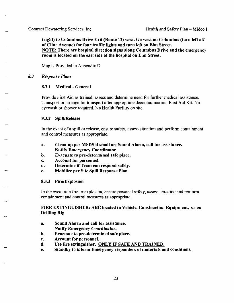
Contract Dewatering Services, Inc. Health and Safety Plan - Midco I
(right) to Columbus Drive Exit (Route 12) west. Go west on Columbus (turn left offof Cline Avenue) for four traffic lights and turn left on Elm Street.NOTE: There are hospital direction signs along Columbus Drive and the emergencyroom is located on the east side of the hospital on Elm Street.
Map is Provided in Appendix D
8.3 Response Plans
8.3.1 Medical - General
Provide First Aid as trained, assess and determine need for further medical assistance.Transport or arrange for transport after appropriate decontamination. First Aid Kit. Noeyewash or shower required. No Health Facility on site.
8.3.2 Spill/Release
In the event of a spill or release, ensure safety, assess situation and perform containmentand control measures as appropriate.
a. Clean up per MSDS if small or; Sound Alarm, call for assistance.Notify Emergency Coordinator
b. Evacuate to pre-determined safe place.c. Account for personnel.d. Determine if Team can respond safely.e. Mobilize per Site Spill Response Plan.
8.3.3 Fire/Explosion
In the event of a fire or explosion, ensure personal safety, assess situation and performcontainment and control measures as appropriate.
FIRE EXTINGUISHER: ABC located in Vehicle, Construction Equipment, or onDrilling Rig
a. Sound Alarm and call for assistance.Notify Emergency Coordinator.
b. Evacuate to pre-determined safe place.c. Account for personnel.d. Use fire extinguisher. ONLY IF SAFE AND TRAINED.e. Standby to inform Emergency responders of materials and conditions.
23

Contract Dewatering Services, Inc. Health and Safety Plan - Midco I
8.3.4 Security Problems
Plan to respond to security problems is to call 911 on mobile phone.
8.3.5 Accident and Incident Reporting
All accidents and injuries must be reported to a foreman or the Site Safety Managerimmediately. The supervisor or contractor representative will complete the reportingprocess as described in the Federal Safety Program.
All environmental, health and safety incidents and data will be recorded in the fieldrecord books. Any OSHA and/or required Federal or State forms or logs will bemaintained at the office of Contract Dewatering.
8.4 Decontamination Plan
Consistent with the levels of protection required, step-by-step procedures for personneldecontamination for each Level of Protection are given below.
LEVEL D / LEVEL C - DECONTAMINATION PLAN
Segregated equipment drop
Tape removal - outer glove and boot
Boot cover removal
Outer glove removal
Suit removal
Inner glove removal
Respirator Cartridges
Drop equipment in a designated area fordecontamination or proper disposal.
If necessary
If necessary , place in trash bag or disposal container
If necessary , place in trash bag or disposal container
If necessary , place in trash bag or disposal container
If necessary , place in trash bag or disposal container
If necessary , place in trash bag or disposal container
CRC / SAFE ZONE BOUNDARY
Field Wash
Disposal Plan,
Disposal Plan,
Disposal Plan,
End of Day
End of week
End of project
Wash hands and face with soap and wateras soon as possible and before eating ordrinking or other hand to mouth activity.
At end of the day the trash bag with thePPE will be closed up and staged in asecure area.
Material will be stored in a secure area.
Material will be disposed of in anappropriately permitted landfill
24
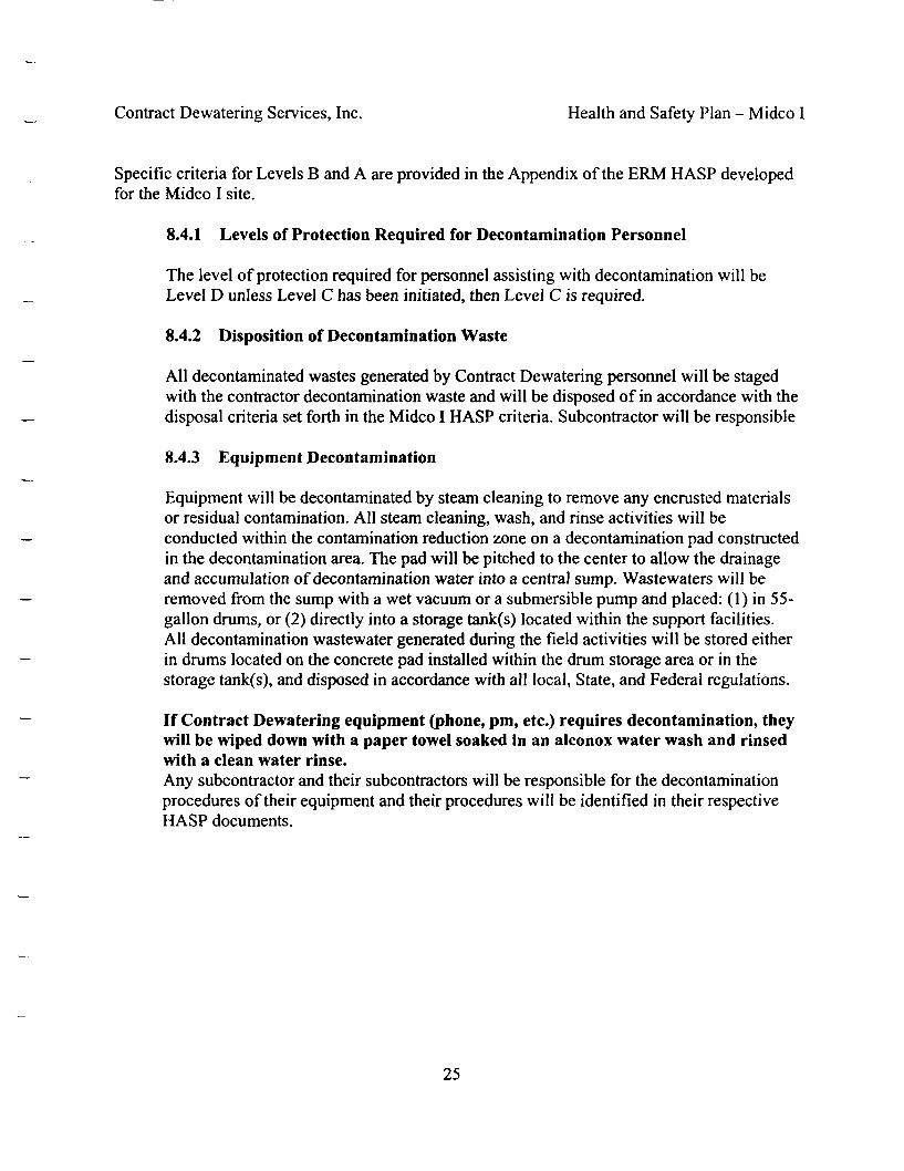
Contract Dewatering Services, Inc. Health and Safety Plan - Midco I
Specific criteria for Levels B and A are provided in the Appendix of the ERM HASP developedfor the Midco I site.
8.4.1 Levels of Protection Required for Decontamination Personnel
The level of protection required for personnel assisting with decontamination will beLevel D unless Level C has been initiated, then Level C is required.
8.4.2 Disposition of Decontamination Waste
All decontaminated wastes generated by Contract Dewatering personnel will be stagedwith the contractor decontamination waste and will be disposed of in accordance with thedisposal criteria set forth in the Midco I HASP criteria. Subcontractor will be responsible
8.4.3 Equipment Decontamination
Equipment will be decontaminated by steam cleaning to remove any encrusted materialsor residual contamination. All steam cleaning, wash, and rinse activities will beconducted within the contamination reduction zone on a decontamination pad constructedin the decontamination area. The pad will be pitched to the center to allow the drainageand accumulation of decontamination water into a central sump. Wastewaters will beremoved from the sump with a wet vacuum or a submersible pump and placed: (1) in 55-gallon drums, or (2) directly into a storage tank(s) located within the support facilities.All decontamination wastewater generated during the field activities will be stored eitherin drums located on the concrete pad installed within the drum storage area or in thestorage tank(s), and disposed in accordance with all local, State, and Federal regulations.
If Contract Dewatering equipment (phone, pm, etc.) requires decontamination, theywill be wiped down with a paper towel soaked in an alconox water wash and rinsedwith a clean water rinse.Any subcontractor and their subcontractors will be responsible for the decontaminationprocedures of their equipment and their procedures will be identified in their respectiveHASP documents.
25
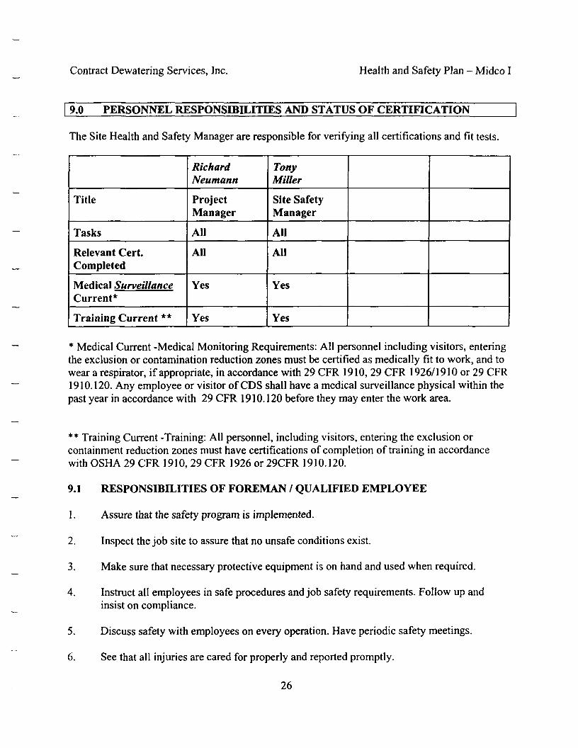
Contract Dewatering Services, Inc. Health and Safety Plan - Midco I
9.0 PERSONNEL RESPONSIBILITIES AND STATUS OF CERTIFICATION
The Site Health and Safety Manager are responsible for verifying all certifications and fit tests.
Title
Tasks
Relevant Cert.Completed
Medical SurveillanceCurrent*
Training Current **
RichardNeumann
ProjectManager
All
All
Yes
Yes
TonyMiller
Site SafetyManager
All
All
Yes
Yes
* Medical Current -Medical Monitoring Requirements: All personnel including visitors, enteringthe exclusion or contamination reduction zones must be certified as medically fit to work, and towear a respirator, if appropriate, in accordance with 29 CFR 1910, 29 CFR 1926/1910 or 29 CFR1910.120. Any employee or visitor of CDS shall have a medical surveillance physical within thepast year in accordance with 29 CFR 1910.120 before they may enter the work area.
** Training Current -Training: All personnel, including visitors, entering the exclusion orcontainment reduction zones must have certifications of completion of training in accordancewith OSHA 29 CFR 1910, 29 CFR 1926 or 29CFR 1910.120.
9.1 RESPONSIBILITIES OF FOREMAN / QUALIFIED EMPLOYEE
1. Assure that the safety program is implemented.
Inspect the job site to assure that no unsafe conditions exist.
Make sure that necessary protective equipment is on hand and used when required.
2.
3.
4. Instruct all employees in safe procedures and job safety requirements. Follow up andinsist on compliance.
5. Discuss safety with employees on every operation. Have periodic safety meetings.
6. See that all injuries are cared for properly and reported promptly.
26

Contract Dewatering Services, Inc. Health and Safety Plan - Midco I
7. Investigate all accidents. File a complete accident report with the Safety Officer andcorrect the causes immediately. Use OSHA FORM 301.
8. Be familiar with the rules pertaining to safety.
9. Report any hazardous conditions to the Safety Officer even if the condition has beencorrected.
10. Recommend reprimands for employees found in non-compliance of safety program andrelated materials.
9.2 DISCIPLINE POLICY
It is the policy of Contract Dewatering to supply its employees with a workplace which is freefrom recognized hazards. Contract Dewatering will provide to each employee the proper tools,equipment, Contract Dewatering is concerned with your safety and requires you to takeadvantage of these measures for your protection.
In order to ensure your compliance with this policy, the following schedule of disciplinary actionshall apply to any employee found to be in violation of the required procedures:
First Offense Written warning filed in employees permanent file (effective forone year from date of issue).
Second Offense Written warning filed in employees permanent file (effective forone year from date of issue).
Third Offense Subject to suspension without pay for a length of time to bedetermined at time of offense.
Subsequent Offenses Subject to dismissal or suspension without pay for a length of timeto be determined at time of offense.
Safety is everyone's' responsibility. The safety rules of Contract Dewatering in place to protectyou and your fellow employees and these rules will be enforced.
Employee Signature:
Date:
27
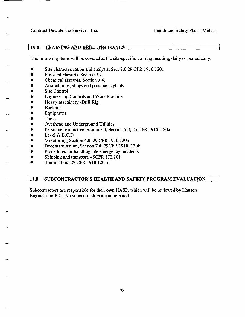
Contract Dewatering Services, Inc. Health and Safety Plan - Midco I
10.0 TRAINING AND BRIEFING TOPICS
The following items will be covered at the site-specific training meeting, daily or periodically:
Site characterization and analysis, Sec. 3.0,29 CFR 1910.1201Physical Hazards, Section 3.2.Chemical Hazards, Section 3.4.Animal bites, stings and poisonous plantsSite ControlEngineering Controls and Work PracticesHeavy machinery -Drill RigBackhoeEquipmentToolsOverhead and Underground UtilitiesPersonnel Protective Equipment, Section 5.4; 25 CFR 1910 .120aLevel A,B,C,DMonitoring, Section 6.0; 29 CFR 1910 120hDecontamination, Section 7.4; 29CFR 1910, 120kProcedures for handling site emergency incidentsShipping and transport. 49CFR 172.101Illumination. 29 CFR 1910.120m
11.0 SUBCONTRACTOR'S HEALTH AND SAFETY PROGRAM EVALUATION
Subcontractors are responsible for their own HASP, which will be reviewed by HansonEngineering P.C. No subcontractors are anticipated.
28

APPENDIX A

Contract Dewatering Services, Inc. Health and Safety Plan - Midco I
Appendix A
Job Hazard Analysis
MOBILIZATION AND DEMOBILIZATIONHazard:Controls:
a.
b.
c.d.e.f.g-
Hazard:Controls:
a.
d.e.
Equipment Accidents
Assure that all equipment (including trucks) is equipped with ROPS, seatbelts, back-up alarms, and fire extinguishers.Use signaler while loading and unloading. Act only on signaler's signal.Signaler shall wear a reflective orange vest.Assure that all equipment is in safe operating condition.Limit loading and off-loading during wet or freezing conditions.Require use of seat belts.Use only trained and authorized equipment operators.Equipment inspections at the start of each shift. All equipment removedand subsequently returned to the site shall be reinserted.
Material Handling Accidents
Furnish personal protective equipment such as hard hats, gloves,protective shoes, eye protection, etc.Instruct employees in proper lifting techniques to prevent back injury.Reinforce proper lifting technique when lifting observed.Use equipment whenever possible for lifting (with proper liftingapparatus.)Disallow employee's exposure to suspended loadsUse only qualified "riggers" for hooking, lifting and landing materials.
FUEL STORAGE AND EQUIPMENT REFUELINGHazard: FireControls:a. Furnish and mount fire extinguishers.
Place "No Smoking" and "No Open Flame" signs on storage tanks.Place dikes around storage tanks.Prohibit smoking or open flames with 50 feet of where equipment is beingrefueled.Dispensing systems shall be electrically bonded and grounded.Portable fuel containers shall be approved safety cans.Storage tanks shall be equipped with relief valves.
b.c.d.
e.f.g-
A-l
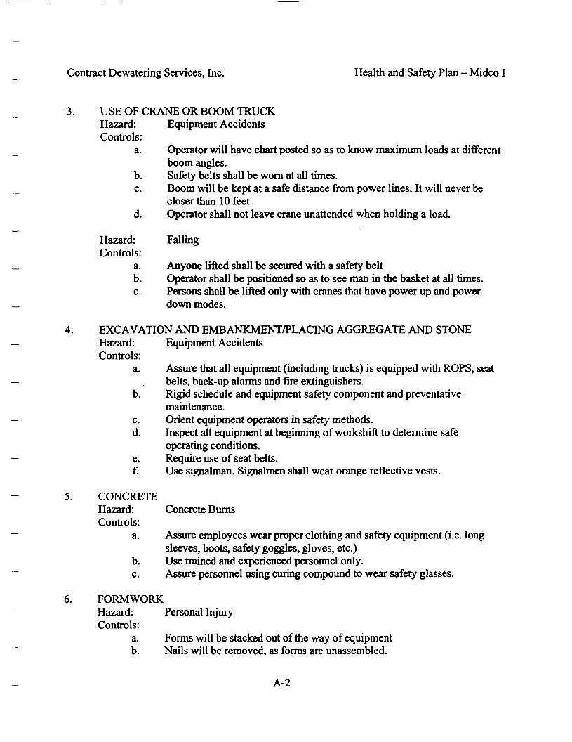
Contract Dewatering Services, Inc. Health and Safety Plan - Midco I
USE OF CRANE OR BOOM TRUCKHazard:Controls:
a.
b.c.
d.
Hazard:Controls:
a.b.c.
Equipment Accidents
Operator will have chart posted so as to know maximum loads at differentboom angles.Safety belts shall be worn at all times.Boom will be kept at a safe distance from power lines. It will never becloser than 10 feetOperator shall not leave crane unattended when holding a load.
Falling
Anyone lifted shall be secured with a safety beltOperator shall be positioned so as to see man in the basket at all times.Persons shall be lifted only with cranes that have power up and powerdown modes.
EXCAVATION AND EMBANKMENT/PLACING AGGREGATE AND STONEHazard: Equipment AccidentsControls:
a. Assure that all equipment (including trucks) is equipped with ROPS, seatbelts, back-up alarms and fire extinguishers.
b. Rigid schedule and equipment safety component and preventativemaintenance.
c. Orient equipment operators in safety methods.d. Inspect all equipment at beginning of workshift to determine safe
operating conditions.e. Require use of seat belts.f. Use signalman. Signalmen shall wear orange reflective vests.
CONCRETEHazard: Concrete BurnsControls:
a. Assure employees wear proper clothing and safety equipment (i.e. longsleeves, boots, safety goggles, gloves, etc.)
b. Use trained and experienced personnel only.c. Assure personnel using curing compound to wear safety glasses.
FORMWORKHazard: Personal InjuryControls:
a. Forms will be stacked out of the way of equipmentb. Nails will be removed, as forms are unassembled.
A-2
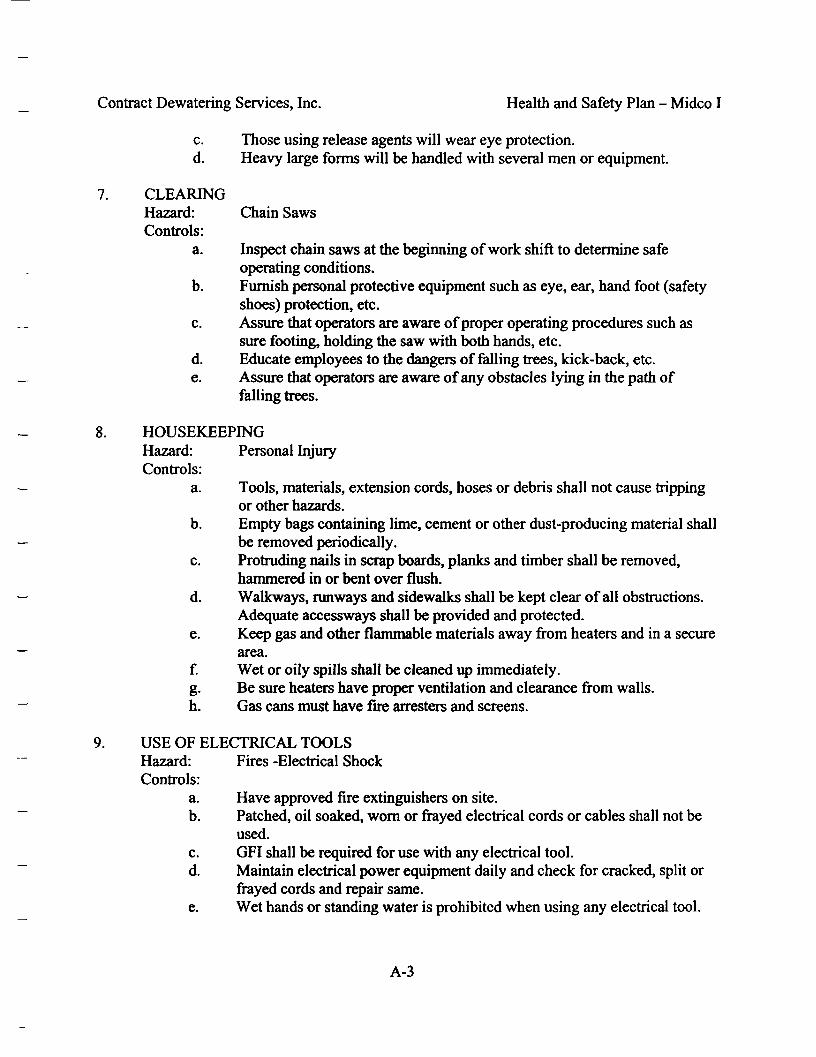
Contract Dewatering Services, Inc. Health and Safety Plan - Midco I
c. Those using release agents will wear eye protection.d. Heavy large forms will be handled with several men or equipment.
7. CLEARINGHazard: Chain SawsControls:
a. Inspect chain saws at the beginning of work shift to determine safeoperating conditions.
b. Furnish personal protective equipment such as eye, ear, hand foot (safetyshoes) protection, etc.
c. Assure that operators are aware of proper operating procedures such assure footing, holding the saw with both hands, etc.
d. Educate employees to the dangers of falling trees, kick-back, etc.e. Assure that operators are aware of any obstacles lying in the path of
falling trees.
8. HOUSEKEEPINGHazard: Personal InjuryControls:
a. Tools, materials, extension cords, hoses or debris shall not cause trippingor other hazards.
b. Empty bags containing lime, cement or other dust-producing material shallbe removed periodically.
c. Protruding nails in scrap boards, planks and timber shall be removed,hammered in or bent over flush.
d. Walkways, runways and sidewalks shall be kept clear of all obstructions.Adequate accessways shall be provided and protected.
e. Keep gas and other flammable materials away from heaters and in a securearea.
f. Wet or oily spills shall be cleaned up immediately.g. Be sure heaters have proper ventilation and clearance from walls,h. Gas cans must have fire arresters and screens.
9. USE OF ELECTRICAL TOOLSHazard: Fires -Electrical ShockControls:
a. Have approved fire extinguishers on site.b. Patched, oil soaked, worn or frayed electrical cords or cables shall not be
used.c. GFI shall be required for use with any electrical tool.d. Maintain electrical power equipment daily and check for cracked, split or
frayed cords and repair same.e. Wet hands or standing water is prohibited when using any electrical tool.
A-3

Contract Dewatering Services, Inc. Health and Safety Plan - Midco I
f. Make absolutely sure that the electrical power tool being used has a trueground or is double insulated.
g. Do not abuse or misuse power tools or handle them by their electricalcords.
10. POWER TOOLSHazard: Personal InjuryControls:
a. Power tools shall not be left running and unattended. Only experiencedoperators will be allowed to use power tools.
b. Eye protection, face shields, and hearing protection shall be worn.c. Proper personnel safety equipment shall be used.d. Use the right tool for the right job.e. Tools shall be kept in proper working order and checked daily, including
protective guards.f. Electrical cords shall be in good condition and properly grounded.g. Avoid using aluminum or other metal ladders on electrical jobs or near
electrical lines.
11. DRILLING EQUIPMENTHazard: Personal InjuryControls:
a. Equipment operators shall be properly trained in the operation of theirspecific type of drilling rig.
b. Make sure drilling rig has gone through a visual inspection to identify anypresent safety hazards.
c. Be sure that all guards are in place and all pinch points are identified.d. Proper eye and ear protection must be worn at all times.e. Drill rig shall be equipped with a fire extinguisher, OSHA approved first
aid kit, and OSHA approved safety belts and lanyards for climbing on rigor derrick.
f. Helpers and support personnel shall be briefed on all related health andsafety hazards prior to beginning each phase of the work.
g. Any open hole shall not be left unprotected; it shall be covered andidentified with a caution tape barrier.
h. All lifting apparatuses, cable and rigging hardware shall be visuallyinspected daily and any deficient equipment or material shall be replacedbefore any work may continue,
i. Weather conditions shall be monitored and at the first sight of lightning,the drilling crew will shut down until the threat of lightning is out of thearea,
j. Should any drilling fluids be used, MSDS sheets will be available forreview by any workers on site.
A-4

Contract Dewatering Services, Inc. Health and Safety Plan - Midco I
k. When any drilling is performed on sheeting cells or near sheetedexcavations where a falling hazard would occur, hand rails must be inplace before CDS employees can begin any of their work.
1. On any drilling location, if open water hazards are present, PFD's will beworn by the workers that are in the hazard areas.
12. USE OF CRANE OR BOOM TRUCKa. Hazard: Equipment Accidents
Controls:1. Operator will have chart posted so as to know maximum loads at different
boom angles.2. Safety belts shall be worn at all times.3. Boom will be kept at a safe distance from power lines. It will never be
closer than ten feet.4. Operator shall not leave crane unattended when holding a load.
b. Hazard: FallingControls:1. Anyone lifted shall be secured with an OSHA approved harness.2. Operator shall be positioned so as to see man in the basket at all times.3. Persons shall be lifted only with cranes that have power up and power
down modes.
13. TRENCHING ACTIVITIES
a. Mobilization and Demobilization1. Hazard: Equipment Accidents
Controls:a. Always check moving permits for any irregularitiesb. Proper loading, always measures height off of groundc Use adequate size and number of chain and binders to secure to
low boy trailer.
b. Slurry Wall Installation1. Hazard: Unloading and Staging the Bentonite
Controls:a. Always be sure to use the proper spreaders. The spreaders must
have four legs.b. Any handling device must be able to support the super sacks by all
four straps.c. Never get under the live load. The straps or lifting device could
fail causing serious injury.
A-5

Contract Dewatering Services, Inc. Health and Safety Plan - Midco I
c. Mixing the Bentonite Slurry1. Hazard: Personal Injury
Controls:a. Dust emissions produced by the bentonite slurry mixing process
will be below nuisance levels; therefore, no mandatory respiratorplan will be required. Dust masks will be available on a voluntarybasis for those who request them as provided for in Appendix D ofthe OSHA Respiration Protection Regulations.
d. Slurry Wall Construction1. Hazard: Open Trench
Controls:a. Keep trench area identified and limit access to personnel not
working on the slurry trench.2. Hazard: Fresh Slurry Trench
a. Limit access into slurry wall construction area until the constructedwall has a cap placed over it. This will prevent anyone fromaccidentally stepping into the slurry trench.
A-6

APPENDIX B
Contract Dewatering Services, Inc. Health and Safety Plan - Midco I
Appendix B
CONTRACT DEWATERING SERVICES INC.EMPLOYEE SIGN-OFF SHEET
_, an employee of CONTRACTDEWATERING SERVICES, INC. have read and understand this health andsafety policy. I also understand that if I have any questions concerning the safetypolicy or safety in general I may contact the company safety officer forclarification. Further, I understand that safety is everyone's responsibility,including my own.
Signed:
Date:
B-l
Contract Dewatering Services, Inc. Health and Safety Plan - Midco I
APPENDIX C
MSDSCHEMICAL DATA SHEETS
1. Wyo-Ben Hydrogel2. Wyo-Ben SW-101

WYO-BEN, INC.MATERIAL SAFETY DATA SHEET
UiyO-BBILNFPA FIRE HAZARD
IDENTIFICATION SYSTEM
L PRODUCT IDENTIFICATION
Trade Name(s): HYDROGEL*
Generic Name(s): Wyoming (Western) Bentonite; Bentonite Clay (CAS No. 1302-78-9)
Chemical Name(s): Sodium Montmorillonite (CAS No. 1318-93-0)
ManufacturerAddress:
WYO-BEN, INC.P.O. Box 1979Billings, Montana S9103
Telephone Numbers:Information: (406)652-6351EMERGENCY: (406)652-6351
Q. HAZARDOUS INGREDIENTS
Ingredient CAS NO. Hazard
Crystalline Silica(SiQj) as Quartz
14808-60-7 See Note Low concentrations of crystalline silica (SiOj) in the form ofquartz may be present in airborne bentonite dust See Section VIfor discussion of health hazard.
Note: Although the typical quartz content of western bentonite is in the range of 2 to 6% most of the quartz particles are larger thanthe 10 u respirable threshold size. The actual respirable quartz concentration in airborne bentonite dust will depend uponbentonite source, fineness of product, moisture content of product, local humidity and wind condition at point of use andother use specific factors.
PHYSICAL DATA
Boiling Point (T): NA Specific Gravity (HzO=l): 2.45-2.55
Vapor Pressure (mm. Hg): NA Melting Point Approx. 1450°C
Vapor Density (Air =1): NA Evaporation Rate (Butyl Acetate =1): NA
Solubility in Water. Insoluble, forms colloidal suspension. pH: 8-10 (5% aqueous suspension)
Density (at 20° C): 55 Ibs./cu.ft as product
Appearance and Odor: Bluegray to green as moist solid, light tan to gray as dry powder. No odor.
IV. FIRE AND EXPLOSION DATA
Flash Point NA Flammable Limits: LEL: NA UEL: NA
Special Fire Fighting Procedures: NA
Unusual Fire and Explosion Hazards: None. Product will not support combustion.
Extinguishing Media: None for product Any media can be used for the packaging. Product becomes slippery when wet
V. REACTIVITY
Stability: Stable
Hazardous Polymerization: None
Incompatibility: None
Hazardous Decomposition Products: None
NA= Not Applicable ND = Not Determined
Date Prepared: March 15,2001 Doc#: 1020-00
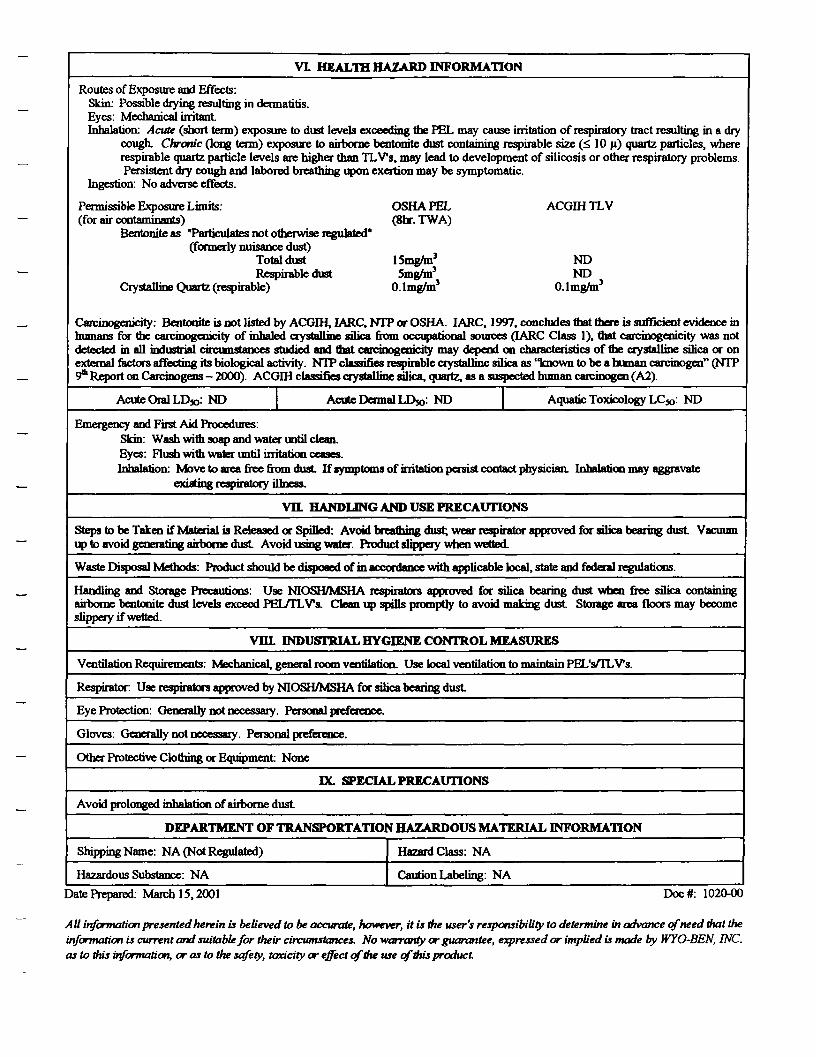
VL HEALTH HAZARD INFORMATION
Routes of Exposure and Effects:Skin: Possible drying resulting in dermatitis.Eyes: Mechanical irritantInhalation: Acute (short term) exposure to dust levels exceeding the PEL may cause irritation of respiratory tract resulting in a dry
cough. Chronic (long term) exposure to airborne bentonite dust containing respirable size (<l 10 u) quartz particles, whererespirable quartz particle levels are higher than TLVs, may lead to development of silicosis or other respiratory problems.Persistent dry cough and labored breathing upon exertion may be symptomatic.
Ingestion: No adverse effects.
Permissible Exposure Limits: OSHAPEL ACGIHTLV(for air contaminants) (ghr. TWA)
Bentonite as "Particulates not otherwise regulated"(formerly nuisance dust)
Total dust 15mg/m3 NDRespirable dust Smg/m3 ND
Crystalline Quartz (respirable) O.lmg/m3 O.lmg/m3
Carcinogenicity: Bentonite is not listed by ACGIH, IARC, NTP or OSHA. I ARC, 1997, concludes mat there is sufficient evidence inhumans for the carcinogenicity of inhaled crystalline silica from occupational sources (IARC Class IX mat Carcinogenicity was notdetected in all industrial circumstances studied and mat carcinogenicity may depend on characteristics of me crystalline silica or onexternal factors affecting its biological activity. NTP classifies respirable crystalline silica as "known to be a human carcinogen" (NTP9th Report on Carcinogens — 2000). ACGIH classifies crystalline silica, quartz, as a suspected human carcinogen (A2).
Acute Oral LD»: ND Acute Dermal LDso: ND Aquatic Toxicology LC»: ND
Emergency and First Aid Procedures:Skin: Wash with soap and water until clean.Eyes: Flush with water until irritation ceases.Inhalation: Move to area free from dust If symptoms of irritation persist contact physician. Inhalation may aggravate
existing respiratory illness.
Vtt HANDLING AND USE PRECAUTIONS
Steps to be Taken if Material is Released or Spilled: Avoid breaming dust; wear respirator approved for silica bearing dust Vacuumup to avoid generating airborne dust Avoid using water. Product slippery when wetted.
Waste Disposal Methods: Product should be disposed of in accordance with applicable local, state and federal regulations.
Handling and Storage Precautions: Use NIOSH/MSHA respirators approved for silica bearing dust when free silica containingairborne bentonite dust levels exceed PEL/TLVs, Clean up spills promptly to avoid making dust Storage area floors may becomeslippery if wetted.
INDUSTRIAL HYGIENE CONTROL MEASURES
Ventilation Requirements: Mechanical, general room ventilation. Use local ventilation to maintain PEL's/TLVs.
Respirator Use respirators approved by NIOSH/MSHA for silica bearing dust
Eye Protection: Generally not necessary. Personal preference.
Gloves: Generally not necessary. Personal preference.
Other Protective Clothing or Equipment None
DC. SPECIAL PRECAUTIONS
Avoid prolonged inhalation of airborne dust
DEPARTMENT OF TRANSPORTATION HAZARDOUS MATERIAL INFORMATION
Shipping Name: NA (Not Regulated)
Hazardous Substance: NA
Hazard Class: NA
Caution Labeling: NA
Date Prepared: March 15,2001 Doc #: 1020-00
A U information presented herein is believed to be accurate, however, it is the user's responsibility to determine in advance of need that theinformation is current and suitable for their circumstances. No 'warranty or guarantee, expressed or implied is made by WYO-BEN, INC.as to this information, or as to the safety, tenacity or effect of the use of this product
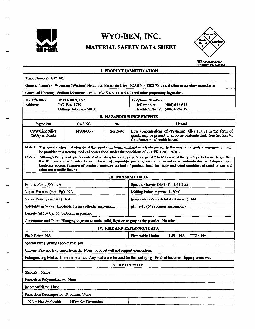
WYO-BEN, INC.MATERIAL SAFETY DATA SHEET
NFP A FIRE HAZARD
IDBHTTF1CAT1ON SYSTEM
L PRODUCT IDENTIFICATION
Trade Name(s): SW 101
Generic Name(s): Wyoming (Western) Bentonite; Bentonite Chy (CAS No. 1302-78-9) and other proprietary ingredients
Chemical Name(s): Sodium Montmorillonite (CAS No. 1318-93-0) and other proprietary ingredients
ManufacturerAddress:
WYO-BEN, INC.P.O. Box 1979Billings, Montana 59103
Telephone Numbers:Information: (406) 652-6351EMERGENCY: (406)652-6351
H HAZARDOUS INGREDIENTS
Ingredient
Crystalline Silica(SiOj) as Quartz
CAS NO.
14808-60-7
%
See Note
Hazard
Low concentrations of crystalline silica (SiOj) in the form ofquartz may be present in airborne bentonhe dust See Section VIfor discussion of health hazard.
Note 1: The specific chemical identity of this product is being •withheld as a trade secret In the event of a medical emergency it willbe provided to a treating medical professional under fte provisions of 29 CFR 1910.1200(1).
Note 2: Although the typical quartz content of western bentonite is in the range of 2 to 6% most of the quartz particles are larger thanthe 10 n respirable threshold size. The actual respirable quartz concentration in airborne bentonite dust will depend uponbentonite source, fineness of product, moisture content of product, local humidity and wind condition at point of use andother use specific factors.
DL PHYSICAL DATA
Boiling Point (°F): NA
Vapor Pressure (mm. Hg): NA
Vapor Density (Air =1): NA
Solubility in Water: Insoluble, forms colloidal suspension.
Density (at 20° C): 55 Ibs./caft. as product
Specific Gravity (HjO=l): 2.45-2.55
Melting Point Approx. 1450°C
Evaporation Rate (Butyl Acetate =1): NA
pH: 8- 10 (5% aqueous suspension)
Appearance and Odor: Bluegray to green as moist solid, light tan to gray as dry powder. No odor.
IV. FRE AND EXPLOSION DATA
Flash Point NA Flammable Limits: LEL: NA UEL: NA
Special Fire Fighting Procedures: NA
Unusual Fire and Explosion Hazards: None. Product will not support combustion.
Extinguishing Media: None for product Any media can be used for the ponging Product becomes slippery when wet
V. REACTIVITY
Stability: Stable
Hazardous Polymerization: None
Incompatibility: None
Hazardous Decomposition Products: None
NA = Not Applicable ND = Not Determined

Doc*: 436CMX)
Augu.t30.2001

VI HEALTH HAZARD INFORMATION
Routes of Exposure and Effects:Skin: Possible drying resulting in dermatitis.Eyes: Mechanical irritantInhalation: Acute (short term) exposure to dust levels exceeding the PEL may cause irritation of respiratory tract resulting in a dry
cough. Chrome (long term) exposure to airborne bentonitc dust containing rcspirablc size (<> 10 p) quartz particles, whererespirable quartz particle levels are higher than TLV's, may lead to development of silicosis or other respiratoryproblems. Persistent dry cough and labored breathing upon exertion may be symptomatic.
Ingestion. No adverse effects.
Permissible Exposure Limits: OSHAPEL ACGIHTLV(for air contaminants) (8hr. TWA)
Bentoniteas "Particulates not otherwise regulated"(formerly nuisance dust)
Total dust ISmgAn3 NDRespirable dust Smg/m3 ND
Crystalline Quartz (respirable) O.lmg/m3 O.lmg/m3
Carcinogenicity: Bentonite is not listed by ACGffl, IARC, NTP or OSHA. LARC, 1997, concludes that there is sufficient evidence inhumans for the carcinogenicity of inhaled crystalline silica from occupational sources (LARC Class 1), that carcinogenicity was notdetected in all industrial circumstances studied and mat carcinogenicity may depend on characteristics of (he crystalline silica or onexternal factors affecting its biological activity. NTP classifies respirable crystalline silica as "known to be a human carcinogen" (NTP9th Report on Carcinogens - 2000). ACGIH classifies crystalline silica, quartz, as a suspected human carcinogen (A2).
Acute Oral LDx>: ND Acute Dermal LD»: ND Aquatic Toxicology LCjo: ND
Emergency and First Aid Procedures:Skin: Wash with soap and water until clean.Eyes: Flush with water until irritation ceases.Inhalation: Move to area free from dust If symptoms of irritation persist contact physician. Inhalation may aggravate
existing respiratory illness.
VH HANDLING AND USE PRECAUTIONS
Steps to be Taken if Material is Released or Spilled: Avoid breaming dust; wear respirator approved for silica bearing dust Vacuumup to avoid generating airborne dust Avoid using water. Product slippery when wetted.
Waste Disposal Methods: Product should be disposed of in accordance with applicable local, state and federal regulations.
Handling and Storage Precautions: Use NIOSH/MSHA respirators approved for silica bearing dust when free silica containingairborne bentonite dust levels exceed PEL/TLVs. Clean up spills promptly to avoid making dust Storage area floors may becomeslippery if wetted.
Vffl. INDUSTRIAL HYGIENE CONTROL MEASURES
Ventilation Requirements: Mechanical, general room ventilation. Use local ventilation to maintain PEL's/TLVs.
Respirator Use respirators approved by NIOSH/MSHA for silica bearing dust
Eye Protection: Generally not necessary. Personal preference.
Gloves: Generally not necessary. Personal preference.
Other Protective Clothing or Equipment None
K. SPECIAL PRECAUTIONS
Avoid prolonged inhalation of airborne dust
DEPARTMENT OF TRANSPORTATION HAZARDOUS MATERIAL INFORMATION
Shipping Name: NA (Not Regulated)
Hazardous Substance: NA
Hazard Class: NA
Caution Labeling: NA
Date Prepared: August 30,2001 Doc#: 4360-00
All information presented herein is believed to be accurate, however, it is the user's responsibility to determine in advance of need that theinformation is current and suitable for their circumstances. No warranty or guarantee, expressed or implied is made by WYO-BEN, INC.as to this information, or as to the safety, toxicity or effect of the use of this product

Contract Dewatering Services, Inc. Health and Safety Plan - Midco I
APPENDIX D
Figure 3-1 - Map from Site to Nearest Hospital (as provided in ERM Site HASP)
Figure 7-2 - Hydrogen Cyanide Monitoring and Response Flow Chart (asprovided in ERM Site HASP)
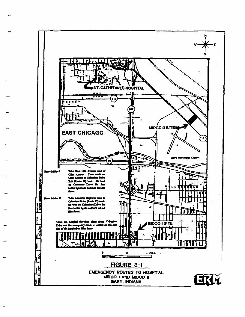
ST. CATHERINES HOSPITAL
MIOCO II SITE
EAST CHICAGO
O* VM •• €«*•*• MM fcctar MB* %tai «< m ht ••
MIDCOI SITE
FIGURE 3-1EMERGENCY ROUTES TO HOSPITAL
MDCO I AND MIDCO IGARY, NDIANA
r
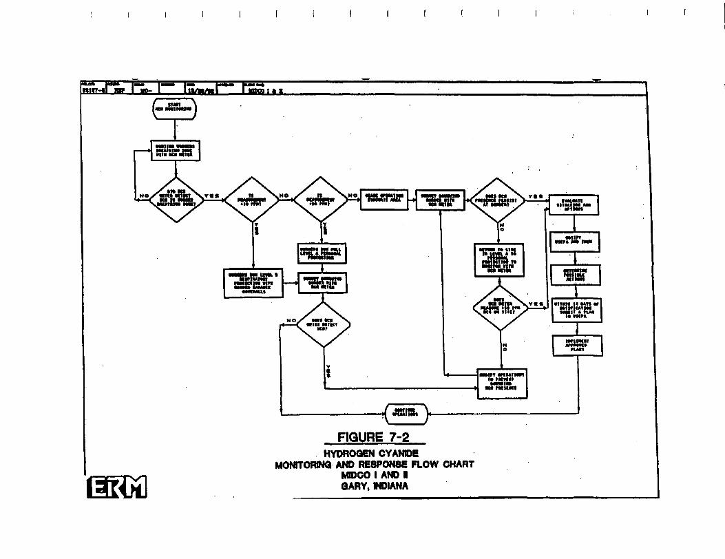
FIGURE 7-2HYDROQEN CYANIDE
MONTORINQ AND RESPONSE FLOW CHARTMDCO I AND IGARY, MDIANA
Contract Dewatering Services, Inc. Health and Safety Plan - Midco I
APPENDIX E
Table 4-1 (Updated November 2003) - Exposure Limits andRecognition Qualities of Various Compounds
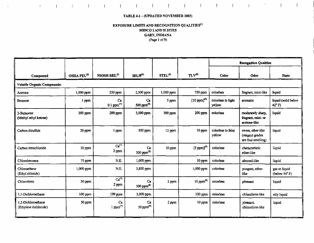
TABLE 4-1 - (UPDATED NOVEMBER 2003)
EXPOSURE LIMITS AND RECOGNITION QUALITIES0'MTOCOI AND n SITES
GARY, INDIANA(Page 1 of 9)
Compound OSHAPEL0)
Volatile Organic Compounds:
Acetone
Benzene
2-Butanone(Methyl ethyl ketone)
Carbon disulfide
Carbon tetrachloride
Chlorobenzene
Chloroethane(Ethyl chloride)
Chloroform
1 , 1 -Dichloroethane
1,2-Dichloroethane(Ethylene dichloride)
l.OOOppm
1 ppm
200 ppm
20 ppm
10 ppm
75 ppm
l.OOOppm
50 ppm
100 ppm
50 ppm
NIOSHRELP)
250 ppm
Ca0.1 ppm17'
200 ppm
1 ppm
Ca(7)
2 ppm
N.E.
N.E.
Ca(7>2 ppm
199 ppm
Calppm(7)
IDLH^
2,500 ppm
Ca500ppm(l)
3,000 ppm
500 ppm
Ca300ppm(!)
l.OOOppm
3,800 ppm
Ca500ppm(l)
3,000 ppm
Ca50ppm("
STEL(5) TLV<«
l.OOOppm
5 ppm
300 ppm
12 ppm
10 ppm
2 ppm
2 ppm
750 ppm
[lOppmf
200 ppm
10 ppm
[Sppmf
10 ppm
l.OOOppm
10ppmw
100 ppm
10 ppm
Recognition Qualities
Color Odor State
colorless
colorless to lightyellow
colorless
colorless to faintyellow
colorless
colorless
colorless
colorless
colorless
colorless
migrant, mint-like
aromatic
moderately sharp,fragrant, mint- oracetone-like
sweet, ether-like(reagent gradesare foul smelling)
characteristicether-like
almond-like
pungent, ether-like
pleasant
chloroform-like
pleasant,chloroform-like
liquid
liquid (solid below42° F)
liquid
liquid
liquid
liquid
gas or liquid(below 54° F)
liquid
oily liquid
liquid

TABLE 4-1 - (UPDATED NOVEMBER 2003)
EXPOSURE LIMITS AND RECOGNITION QUALITIES0'
MIDCOI AND H SITESGARY, INDIANA
(Page 2 of 9)
Compound OSHAPEL® NIOSH RELP) IDLH^ STEL(5) TLV<«>
Recognition Qualities
Color Odor State
Volatile Organic Compounds (continued):
1 , 1 -Dichloroethene(Vinylidene chloride)
1 ,2-Dichloropropane(Propylene dichloride)
Ethyl benzene
2-Hexanone(Methyl n-butyl ketone)
Methylene chloride
4-Methyl-2-pentanone(Hexone, Methyl isobutylketone)
Styrene
1 , 1 ,2,2-Tetrachloroethane
Tetrachlorocthene
(Tetrachloroethylene/Perchloroethylene)
Toluene
75ppm
lOOppm
100 ppm
25 ppm
100 ppm
100 ppm
5ppm
100 ppm
200 ppm
Ca(7)
100 ppm
Ippm
Ca(7>
50 ppm
50 ppm
Calppm(7)
Ca^
100 ppm
Ca400ppm("
800 ppm
1,600 ppm
Ca2,300 ppm(8)
500 ppm
700 ppm
Ca100ppm(8)
150ppm(l)
500 ppm
110 ppm
125 ppm
75 ppm
100 ppm
100 ppm
150 ppm
5 ppm
75 ppm
100 ppm
5 ppm
50ppm(9)
50 ppm
50 ppm
Ippm
[25 ppm]
50 ppm
colorless
colorless
colorless
colorless
colorless
colorless toyellow
colorless to paleyellow
colorless
colorless
chloroform-like
aromatic
acetone-like
chloroform-like
pleasant
sweet, floral
pungent,chloroform-like
mild, chloroform-like
sweet, pungent,benzene-like
liquid
liquid
liquid
liquid (gas above
104° F)
liquid
oily liquid
liquid
liquid
liquid
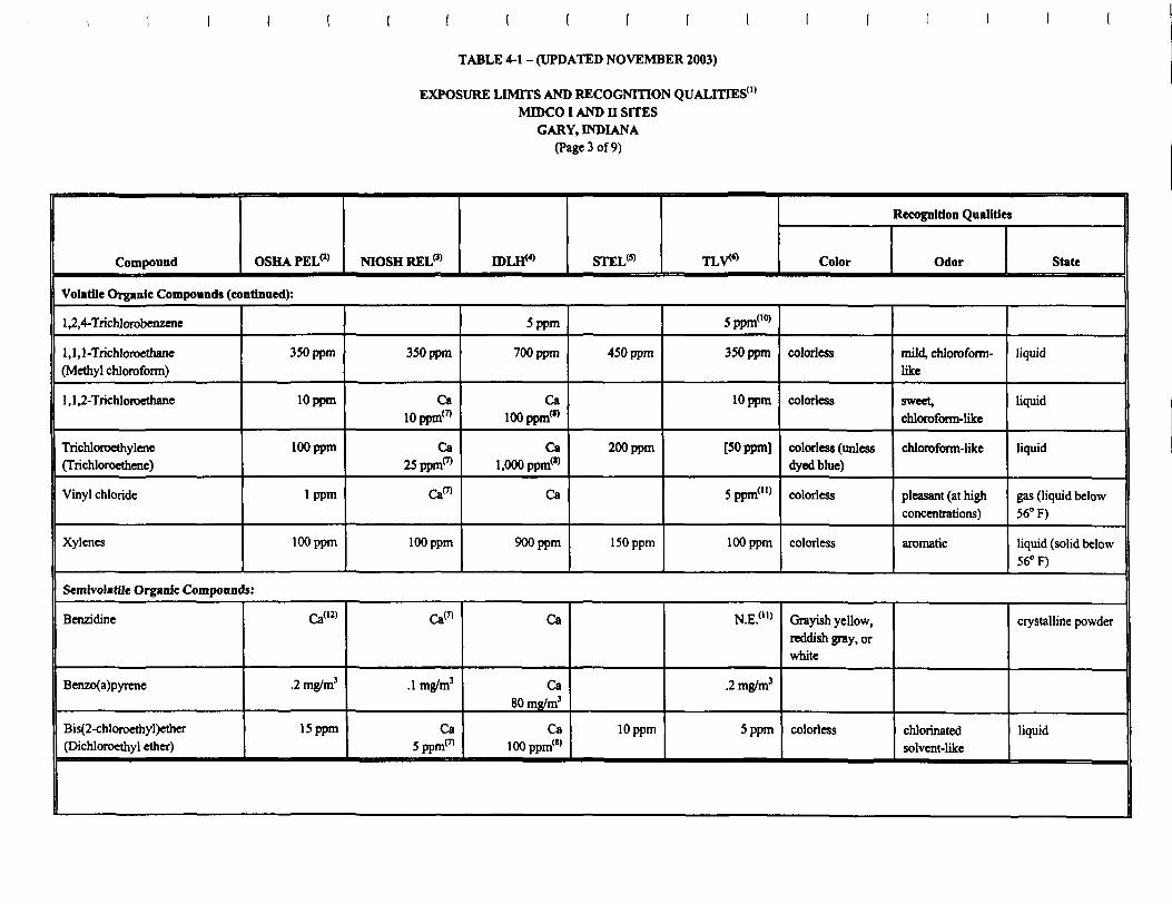
TABLE 4-1 - (UPDATED NOVEMBER 2003)
EXPOSURE LIMITS AND RECOGNITION QUALITIES0'MIDCOI AND H SITES
GARY, INDIANA(Page 3 of 9)
Compound OSHA PELW NIOSHRELP) EDLH^ STEL<5) TLV*
Recognition Qualities
Color Odor State
Volatile Organic Compounds (continued):
1 ,2,4-Trichlorobenzene
1,1,1-Trichloroethane(Methyl chloroform)
1 , 1 ,2-Trichloroethane
Trichloroethylene(Trichloroethene)
Vinyl chloride
Xylenes
350 ppm
lOppm
100 ppm
1 ppm
100 ppm
350 ppm
Ca10ppm<7)
Ca25ppm(7)
Ca™
100 ppm
5 ppm
700 ppm
Ca100ppm(>)
Cal,000ppm(l)
Ca
900 ppm
450 ppm
200 ppm
150 ppm
5ppm(l0)
350 ppm
10 ppm
[50 ppm]
5ppm<">
100 ppm
colorless
colorless
colorless (unlessdyed blue)
colorless
colorless
mild, chloroform-like
sweet,chloroform-like
chloroform-like
pleasant (at highconcentrations)
aromatic
liquid
liquid
liquid
gas (liquid below56° F)
liquid (solid below56° F)
Semlvolatile Organic Compounds:
Benzidine
Benzo(a)pyrene
Bis(2-chloroethyl)ether(Dichloroethyl ether)
Ca(12)
.2 mg/m3
15 ppm
Ca(7)
.1 mg/m3
Ca5ppm(7)
Ca
Ca80 mg/m3
Ca100ppm(8)
10 ppm
N.E.(11)
.2 mg/m3
5 ppm
Grayish yellow,reddish gray, orwhite
colorless chlorinatedsolvent-like
crystalline powder
liquid

TABLE 4-1 - (UPDATED NOVEMBER 2003)
EXPOSURE LIMITS AND RECOGNITION QUALITIES0'MIDCOI AND n SITES
GARY, INDIANA(Page 4 of 9)
Compound OSHA PEL0)
Semivolatile Organic Compounds (continued):
Bis(2-«thylhwty])phthalate(Di-sec octyl phthalate)
Chrysenc
Cresol
1 ,2-Dichlorobenzene(o-Dichlorobenzene)
1 ,4-Dichlorobcnzcne(p-Dichlorobenzene)
Diethyl phthalate
Di-n-butyl phthalate(Dibutyl phthalate)
Isophorone
Naphthalene
4-Nitroaniline
5mg/mJ
.2mg/m3
5ppm
SOppm
75 ppm
5mg/m3
25 ppm
10 ppm
6mg/m3
NIOSH REL(3)
Ca5 mg/mX7)
.1 mg/m3
2.3 ppm
SOppm
Ca(7)
5 mg/m3
5 mg/m3
4 ppm
10 ppm
3 mg/m3
IDLE1"0 STEL(!) TLV«
Ca5,000 mg/m3)
Ca80mg/m3)
250 ppm
200 ppm
Ca150ppm(l)
4,000 mg/m3
200 ppm
250 ppm
300 mg/m3
10 mg/m3
SOppm
110 ppm
15 ppm
5 mg/m3
.2 mg/m3
5 ppm
25 ppm
[10 ppm]
5 mg/m3
5 mg/m3
5ppm(l0)
10 ppm
3 mg/m3
Recognition Qualities
Color Odor State
colorless
colorless, yellow,brown, or pinkish
colorless to paleyellow
colorless or white
colorless to faintyellow
colorless to white
colorless tobrown
bright yellow
slight
sweet, tarry
pleasant, aromatic
mothball-like
slight aromatic
peppermint-like
of mothballs
slight ammonia-like
oily liquid
liquid or solid
liquid
crystalline solid
oily liquid
liquid
solid
crystalline powder

TABLE 4-1 - (UPDATED NOVEMBER 2003)
EXPOSURE LIMITS AND RECOGNITION QUALITIES0'MTOCOI AND 0 SITES
GARY, INDIANA(Page 5 of 9)
Compound OSHAPEL® NIOSHREL^ IDLH^ STEL(5) TLV<*)
Recognition Qualities
Color Odor State
Semlvolatile Organic Compounds (continued):
Nitrobenzene
Pentachlorophenol
Phenol
Ippm
0.5 mg/m3
5ppm
1 ppm
0.5 mg/m3
5ppm
200 ppm
215 mg/m3
250 ppm
1 ppm
0.5 mg/m3
0.5 mg/m3
yellow
colorless to white
colorless to lightpink
pungent odor likepaste shoe polish
benzene-like
sweet, acrid
oily liquid (solidbelow 42° F)
crystalline solid
crystalline solid(liquifies bymixing with about8 percent water)
Pesticides/Polychlorlnated Biphenyb:
Aldrin
Aroclor 1242[Chlorodiphenyl (42 percentchlorine)]
Aroclor-1254[Chlorodiphenyl (54 percentchlorine)]
Chlordane
4,4'-DDT
0.25 mg/m3
lmg/m3
0.5 mg/m3
0.5 mg/m3
1 mg/m3
Ca0.25 mg/m™
Ca0.001 mg/m3™
Ca0.001 mg/mX7)
Ca0.5 ing/m3™
0.5 mg/m3
Ca25 mg/m3<8)
Ca5 mg/m*8'
Ca5 mg/m™
Ca100 mg/*"
500 mg/m3
0.25 mg/m3
1 mg/m3
0.5 mg/m3
0.5 mg/m3
lmg/m3
colorless to darkbrown
colorless to lightcolored
colorless to paleyellow
amber colored
mild chemical
mild hydrocarbon
mild hydrocarbon
pungent, chlorine-like
crystalline solid
viscous liquid
viscous liquid(solid below50° F)
viscous liquid
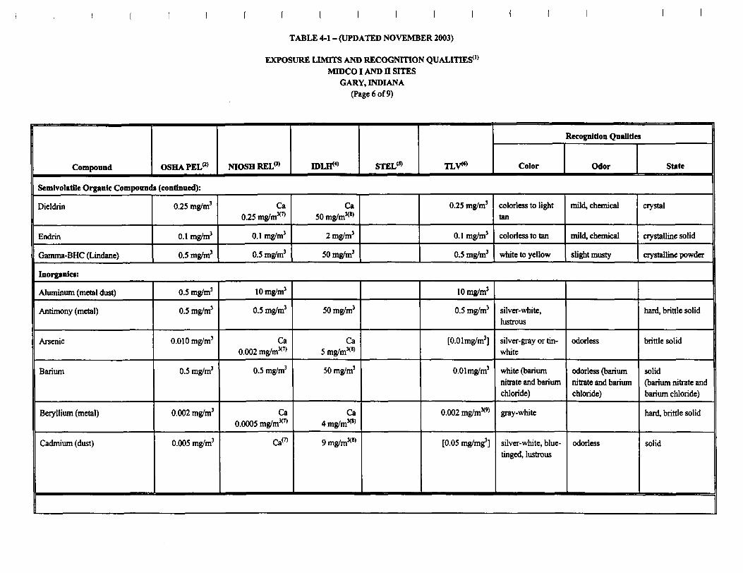
TABLE 4-1 - (UPDATED NOVEMBER 2003)
EXPOSURE LIMITS AND RECOGNITION QUALITIES0*MTOCOI AND H SITES
GARY, INDIANA(Page 6 of 9)
Compound OSHAPELm NIOSH RELm roiflw STEL(5) TLVW
Recognition Qualities
Color Odor State
Semivolatile Organic Compounds (continued):
Dieldrin
Endrin
Gamma-BHC (Lindane)
0.25 mg/m3
0.1 mg/m3
0.5 mg/m3
Ca0.25 mg/m3™
0.1 mg/m3
0.5 mg/m3
CaSOmg/m*'*
2 mg/m3
50 mg/m3
0.25 mg/m3
0.1 mg/m3
0.5 mg/m3
colorless to lighttan
colorless to tan
white to yellow
mild, chemical
mild, chemical
slight musty
crystal
crystalline solid
crystalline powder
Inorganic*:
Aluminum (metal dust)
Antimony (metal)
Arsenic
Barium
Beryllium (metal)
Cadmium (dust)
0.5 mg/m3
0.5 mg/m3
0.010 mg/m3
0.5 mg/m3
0.002 mg/m3
0.005 mg/m3
10 mg/m3
0.5 mg/m3
Ca0.002 mg/m3™
0.5 mg/m3
Ca0.0005 mg/m3™
Ca(7)
50 mg/m3
Ca5 mg/m3*"
50 mg/m3
Ca4mg/m3("
9mg/m3(8)
10 mg/m3
0.5 mg/m3
[O.Olmg/m3]
O.Olmg/m3
0.002 mg/m^
[0.05 mg/mg3]
silver-white,lustrous
silver-gray or tin-white
white (bariumnitrate and bariumchloride)
gray-white
silver-white, blue-tinged, lustrous
odorless
odorless (bariumnitrate and bariumchloride)
odorless
hard, brittle solid
brittle solid
solid(barium nitrate andbarium chloride)
hard, brittle solid
solid

TABLE 4-1 - (UPDATED NOVEMBER 2003)
EXPOSURE LIMITS AND RECOGNITION QUALITIES0'MTOCO I AND n SITES
GARY, INDIANA(Page 7 of 9)
Compound OSHAPELm
Inorganics (continued):
Chromium (metal)
Cobalt (metal)
Copper (dust)
Cyanides
Hydrogen cyanide
Lead (metal)
Manganese
Mercury (vapor)
Nickel (metal)
Selenium
Silver (metal dust)
1 mg/m3
0.1 mg/m3
1 mg/m3
5 mg/m3
lOppm
0.05 mg/m3
5 mg/m3
0.1 mg/m3
1 mg/m3
0.2 mg/m3
0.01 mg/m3
NIOSH REL*3'
0.5 mg/m3
0.05 mg/m3
1 mg/m3
5 mg/m3
4.7 ppm
0.05 mg/m3
1 mg/m3
0.05 mg/m3
CaO.OlSmg/m3™
0.2 mg/m3
0.01 mg/m3
IDLE*4' STEL<5) TLVW
250 mg/m3
20 mg/m3
100 mg/m3
25 mg/m3
50 ppm
100 mg/m3
500 mg/m3
10 mg/m3
Ca10 mg/m3
10 mg/m3
10 mg/m3
4.7 ppm
1 mg/m3
0.5 mg/m3
[0.05 mg/m3]
1 mg/m3
5 mg/m3
10ppm(10)
0.15 mg/m3
[5 mg/m3]
0.05 mg/m3
[1 mg/m3]
0.2 mg/m3
0.1 mg/m3
Recognition Qualities
Color Odor State
blue-white tosteel gray,lustrous
silver-gray toblack
reddish, lustrous
white
colorless or paleblue
soft gray
lustrous, silvery
silver-white
lustrous, silvery
red to gray
white, lustrous
odorless
odorless
faint almond-like
bitter, almond-like
odorless
hard, brittle solid
solid
malleable solid
granular orcrystalline solids
liquid (gas above78° F)
heavy, ductile solid
brittle solid
heavy liquid
solid
crystalline solid
solid

TABLE 4-1 - (UPDATED NOVEMBER 2003)
EXPOSURE LIMITS AND RECOGNITION QUALITIES0'
MTOCOI AND n SITESGARY, INDIANA
(Page 8 of 9)
Compound
Inorganics (continued):
Thallium
Tin
OSHA PELm
0.1 mg/m3
2mg/m3
NIOSH REL0)
0.1 mg/m3
2 mg/m3
TDL&4}
15 mg/m3
100 mg/m3
STEL(5) TLVW
0.1 mg/m3
2 mg/m3
Recognition Qualities
Color
varies
gray to almost
silver-white,lustrous
Odor State
varies varies
malleable solid
Sources:
1 .U.S. Department of Health and Human Services, Public Health Service, NIOSH Website, November 2003.
Notes:
(1)No information is provided in the sources for 41 of the 109 compounds detected at the site. Complete lists of the compounds detected at each site are presented in Tables 1-3 and1-4.
^Occupational Safety and Health Administration (OSHA) permissible exposure limits (PELs) are time-weighted average (TWA) concentrations that must not be exceeded duringany eight-hour work shift of a 40-hour week.
(3)National Institute for Occupational Safety and Health (NIOSH) recommended exposure limits (RELs) are TWA concentrations for up to a 10-hour workday during a 40-hourworkweek.
(4>Immediately Dangerous to Life or Health (IDLH) concentrations represent the maximum concentrations from which a person could escape within 30 minutes without a respiratorand without experiencing any escape-impairing or irreversible health effects.
(5)A short-term exposure limit (STEL) is a 15-minute TWA exposure that should not be exceeded at any time during the workday.
(6)A threshold limit value (TLV), as published by the American Conference of Governmental Industrial Hygienists (ACGIH), is an eight-hour TWA exposure limit

TABLE 4-1 - (UPDATED NOVEMBER 2003)
EXPOSURE LIMITS AND RECOGNITION QUALITIES0'MTOCOI AND n SITES
GARY, INDIANA(Page 9 of 9)
(7)NIOSH-identified occupational carcinogen - reduce exposure to lowest feasible concentration.
(8>The IDLH concentration or designation shown after Ca was determined in the N1OSH Standards Completion Program, and carcinogenic effects were not considered
<9) Suspected human carcinogen according to the ACGIH.
<IO)Ceiling value that should not be exceeded at any time.
""Confined human carcinogen according to the ACGIH.
<12)OSHA-regulated carcinogen - exposure must be controlled through the required use of engineering controls, work practices, and personal protective equipment
Key:
Blank space - No information available in me source material.N.E. - Not established.Ca = Potential human carcinogen.[] = Quantitation proposed to be changed

I2

Mfl SPEC 003
ELECTROFUSION COUPLINGS
Solves the Problem of Difficult Connections
Features
• Engineered For Use On HDPE Pipe
• Size Range l/2"crs-12"ips
• Pressure Rated Up To 160 psi
• PE3408 Resin Complies With ASTMD3350
• NSF Listed Resin
• Meets AWWAC906
• FM Approved
• Complies With ASTM F1055
• Quick and Easy Installation
• Needs No Cumbersome Equipment
Made in U.S.A.
Central Plastics Company1901 W. Independence's!.Shawnee, OK USA 74801
www.centralplastics.com
Michigan Pipe Supply, LLCP.O. Box 442Mount Pleasant, Ml 48804-0442
489-772-2225 FAX 989-772-043&

REV 10/2000 ELECTROFUSION COUPLINGS M/I SPEC 003
1 1/4" SIDR9 DUCT
1 1/2 "IPS
^ HKB^B2 "IPS CONDUIT
iK3" IPS
ASTM D2513
Related Specifications
ASTM Fl 055 • ASTMD1598
ASTMD3350 • ASTM Dl 599
AWWA C906
Fitting RequirementsThese electrofusion fittings are designed and manufactured in accordance with ASTM Specifications F-1055 for usewith pipe conforming to ASTM D2513/3035, F-714 and with Butt fittings conforming to ASTM D3261.Electrofusion fittings can be tested and supplied in accordance with AWWA C906 specification.
These fittings can be supplied with an integral identification resistor which is recognized by aD Central Plastic'sprocessors to automatically set the proper fusion parameters. Electrofusion fittings are supplied with a 24 digitISO recognized barcode label which facilitates the fusion of the Central Plastic electrofusion fitting with othermanufactures processors.
These electrofusion fittings are produced from a PE3408 grade of polyethylene resin which complies with ASTMspecifications D3350. The pre-blended virgin resin has a PPI listing of 3408 that meets or exceeds therequirements of NSF Standard 61.
Required Testing1. Minimum Hydraulic Burst Pressure Test (ASTMD1599)
2. Sustained Pressure Test Results. (ASTMD 1598)Must exceed 170 hoars In 80*C bath at 670 pri hoop stress (134 prig)or exceed 1000 hours In 80*C bath at 580 pri hoop stress (116 prig)(all above criteria are equivalent)
3. Tensile Strength Test
-*••• -Pipe elongation hi excess of 25 */• without separationfrom electrofnrion coupling
4. Joint Integrity TestCrash test of pipe without separation fromelectrofusion coupling.
ISO 9001 CERTIFIED
Central Plastics Company1901 W. Independence St.Shawnee, OK USA 74801
www.centralplastics.com
Phone: 800-654-3872405-273-6302
Fax: 800-733-5993405-273-5993
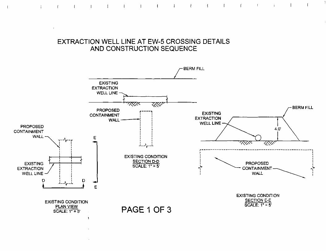
EXTRACTION WELL LINE AT EW-5 CROSSING DETAILSAND CONSTRUCTION SEQUENCE
•BERMFILL
PROPOSEDCONTAINMENT
WALL--r—V-r
EXISTINGEXTRACTION
WELL LINE -
PROPOSEDCONTAINMENT
WALL-
\EXISTING ' J
EXTRACTION /WELL LINE -/
D
•»
^3
D ,»L 1
EXISTING CONDITIONPLAN VIEW
SCALE: 1" = 5'
EXISTING CONDITIONSECTION D-DSCALE: 1" = 5'
PAGE 1 OF 3
EXISTINGEXTRACTION
WELL LINE
BERMFILL
CONTAINMENT -WALL
EXISTING CONDITIONSECTION E-ESCALE: 1" = 5'
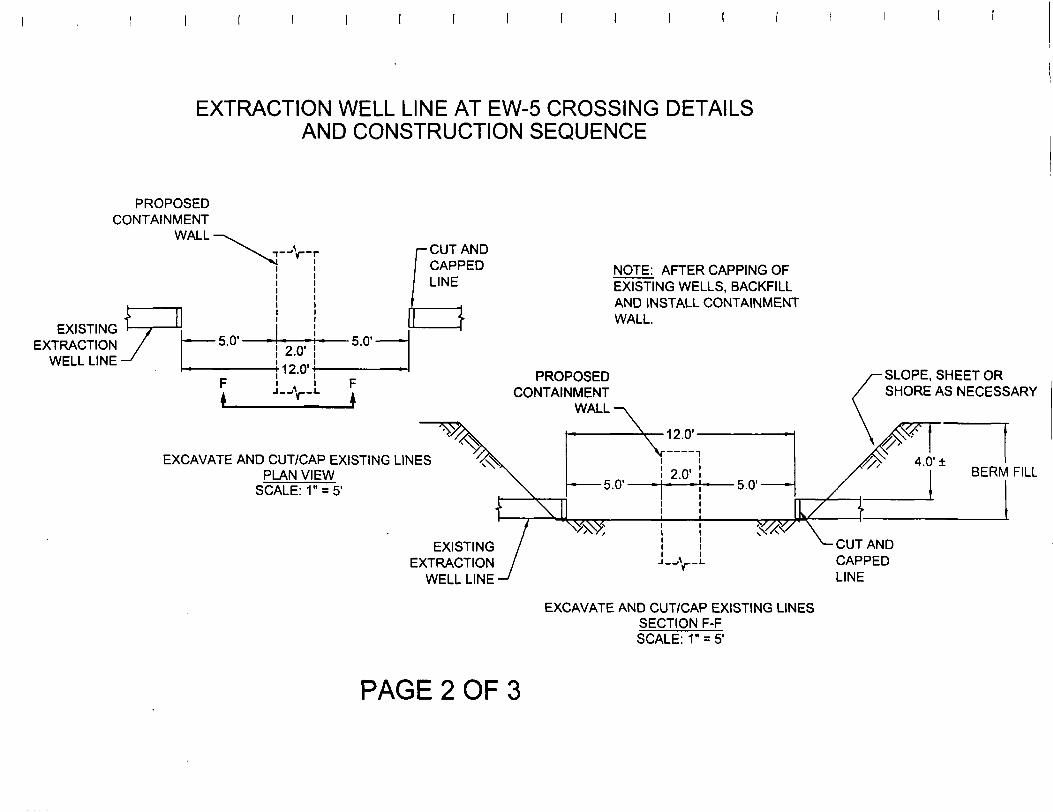
EXTRACTION WELL LINE AT EW-5 CROSSING DETAILSAND CONSTRUCTION SEQUENCE
PROPOSEDCONTAINMENT
WALL
EXISTING ' //EXTRACTION /
WELL LINE -f
^\ i^j
5 n" _
F
-V-
2.0'v -\ 1 (VM^.U 1
.
r
F
r- CUT ANDCAPPEDLINE
}
NOTE: AFTER CAPPING OFEXISTING WELLS, BACKFILLAND INSTALL CONTAINMENTWALL.
PROPOSEDCONTAINMENT
WALL
SLOPE, SHEET ORSHORE AS NECESSARY
EXCAVATE AND CUT/CAP EXISTING LINESPLAN VIEW
SCALE: 1" = 5'BERM FILL
EXISTINGEXTRACTION
WELL LINE
CUT ANDCAPPEDLINE
EXCAVATE AND CUT/CAP EXISTING LINESSECTION F-FSCALE: 1" = 5'
PAGE 2 OF 3
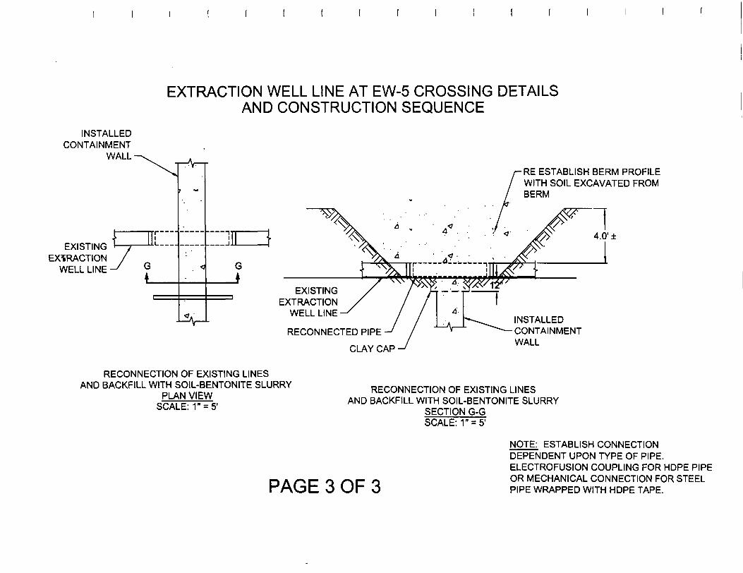
EXTRACTION WELL LINE AT EW-5 CROSSING DETAILSAND CONSTRUCTION SEQUENCE
INSTALLEDCONTAINMENT
WALL-
EXISTINGEXTRACTION
WELL LINE G
L
RE ESTABLISH BERM PROFILEWITH SOIL EXCAVATED FROMBERM
4.0'±
GJ
EXISTINGEXTRACTION
WELL LINE
RECONNECTED PIPE
CLAY CAP
INSTALLEDCONTAINMENTWALL
RECONNECTION OF EXISTING LINESAND BACKFILL WITH SOIL-BENTONITE SLURRY
PLAN VIEWSCALE: 1" = 5'
RECONNECTION OF EXISTING LINESAND BACKFILL WITH SOIL-BENTONITE SLURRY
SECTION G-GSCALE: 1" = 5'
PAGE 3 OF 3
NOTE: ESTABLISH CONNECTIONDEPENDENT UPON TYPE OF PIPE.ELECTROFUSION COUPLING FOR HOPE PIPEOR MECHANICAL CONNECTION FOR STEELPIPE WRAPPED WITH HOPE TAPE.

EXTRACTION WELL LINE AT EW-3 CROSSING DETAILSAND CONSTRUCTION SEQUENCE
PROPOSEDCONTAINMENT
WALL-
\„ y
EXTRACTION /WELL LINE -f
H
j
^ \
PROPOSEDCONTAINMENT
WALL-
EXISTINGEXTRACTION
WELL LINE'
r 1$&* |
4.0'±
EXISTING CONDITIONPLAN VIEW
SCALE: 1" = 5'
EXISTING CONDITIONSECTION H-HSCALE: 1-= 5'
PAGE 1 OF 3

EXTRACTION WELL LINE AT EW-3 CROSSING DETAILSAND CONSTRUCTION SEQUENCE
PROPOSEDCONTAINMENT
WALL-
EXISTINGEXTRACTION
WELL LINE
a2.0' 2.0'
/-CUT ANDCAPPEDLINE
PROPOSEDCONTAINMENT
WALL
2.0'
J—'V-LEXISTING
EXTRACTIONWELL LINE
ASLOPE AS/ NECESSARY
4.0'±
CUT ANDCAPPEDLINE
EXCAVATE AND CUT/CAP EXISTING LINESPLAN VIEW
SCALE: 1" = 5'
EXCAVATE AND CUT/CAP EXISTING LINESSECTION l-l
SCALE: 1" = 5'
NOTE: AFTER CAPPING OFEXISTING WELLS, BACKFILLAND INSTALL CONTAINMENTWALL.
PAGE 2 OF 3

EXTRACTION WELL LINE AT EW-3 CROSSING DETAILSAND CONSTRUCTION SEQUENCE
INSTALLEDCONTAINMENT
WALL'
-ROAD PLATE ORSHEETING ASNECESSARY
EXISTINGEXTRACTION
WELL LINE
Cn
CLAY CAPFILL EXCAVATION WITHSOIL-BENTONITE MIXTURE
4.0'±
EXISTINGEXTRACTION
WELL LINE
RECONNECTED PIPE
INSTALLEDCONTAINMENTWALL
RECONNECTION OF EXISTING LINESAND BACKFILL WITH SOIL-BENTONITE SLURRY
PLAN VIEWSCALE: 1" = 5'
RECONNECTION OF EXISTING LINESAND BACKFILL WITH SOIL-BENTONITE SLURRY
SECTION J-JSCALE: 1" = 5'
PAGE 3 OF 3NOTE: ESTABLISH CONNECTIONDEPENDENT UPON TYPE OF PIPE.ELECTROFUSION COUPLING FOR HOPE PIPEOR MECHANICAL CONNECTION FOR STEELPIPE WRAPPED WITH HOPE TAPE.
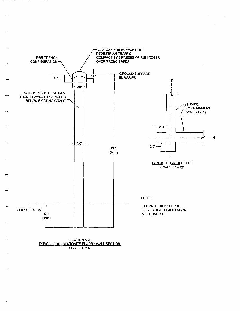
PRE-TRENCHCONFIGURATION
18' —
SOIL- BENTONITE SLURRYTRENCH WALL TO 12 INCHES
BELOW EXISTING GRADE
CLAY CAP FOR SUPPORT OFPEDESTRIAN TRAFFICCOMPACT BY 5 PASSES OF BULLDOZEROVER TRENCH AREA
CLAY STRATUM5.01
(MIN)
\
2.0'
- GROUND SURFACEEL VARIES
2.01
2' WIDECONTAINMENTWALL (TYP.)
-^4^=133.01
(MIN)
2.0'-
I
TYPICAL CORNER DETAILSCALE: 1" = 12'
NOTE:
OPERATE TRENCHER AT90° VERTICAL ORIENTATIONAT CORNERS
SECTION A-ATYPICAL SOIL- BENTONITE SLURRY WALL SECTION
SCALE: 1" = 6'

•5.0'-BLAINE STREET
" WIDTH VARIES-5.0'-
SOLVENT WELDSHEETING
INTERLOCKSFULL LENGTH
SOIL-BENTONITESLURRY WALL
-SHEET PILE CUT OFF WALL,SHOREGARD PVC SHEET PILES, S 300
PLAN VIEWSCALE: 1" = 5'
•PERIMETER OF AGGREGATEBASE AND GEOTEXTILE
ROAD CROSSING DETAILSPAGE 1 OF 2

DENSE GRADED AGGREGATEBASE (INDOT NO. 53)
SEE DETAIL X
MIRAFI MIRAGRID8XT GEOGRID
DENSE GRADED AGGREGATEBASE (INDOT NO. 53)
MIRAFI HP570 WOVENGEOTEXTILE
S 300 SHEET PILE
^_ —SOIL-BENTONITESLURRY WALL
SECTION C-CSCALE: 1" = 5'
DENSE GRADED AGGREGATEBASE (INDOT NO. 53)
FLUSH WITHSHEETING,CUT TO FIT
MIRAFI MIRAGRID8XT GEOGRID
DENSE GRADED AGGREGATEBASE (INDOT NO. 53)
MIRAFI HP570 WOVENGEOTEXTILE
SHOREGARD S 300 SHEET PILE
SOIL-BENTONITESLURRY WALL
DETAIL XSCALE: NONE
ROAD CROSSING DETAILSPAGE 2 OF 2
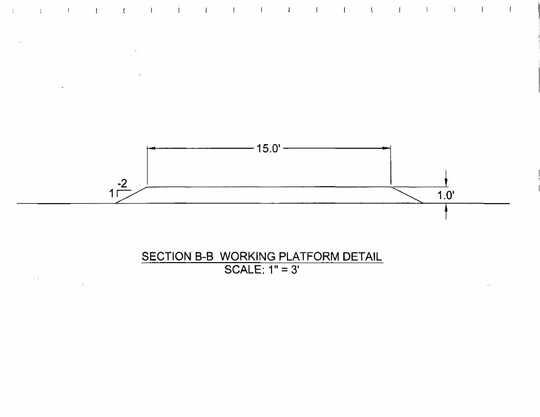
I I I I
-2
— • io.u -
I^\ 1.0'
SECTION B-B WORKING PLATFORM DETAILSCALE: 1" = 3'

Isa.H"

Midco I Containment Barrier Wall
Specifications for Soil- Bentonite ContainmentBarrier Wall
Part 1 General
1.1 ScopeA. The scope of this specification includes all materials, equipment and personnel
required to construct a vertical containment barrier wall along the alignment shownon Drawing 02144-011 A. The purpose of this work is to construct a soil-bentonitecutoff wall extending from the ground surface to a minimum of 5 feet below thesurface of an appropriate key-in material. The key-in material shall be a silty claydeposit is approximately 27 to 28 feet below the existing ground surface(approximately elevation 566 to 570 NGVD). The containment barrier wall (CBW)is to be constructed using a one pass trencher capable of thoroughly blending a soil -water -bentonite into a uniform mixture. The final soil-bentonite mix is to contain 4pounds of bentonite by dry weight 100 pounds of dry weight of trench soil.
Part 2 Materials
2.1 Bentonite
A. Along the east wall of the containment barrier the bentonite material shall consist ofHydrogel 90 as manufactured by Wyo-Ben, Inc.
B. Along the north, south, and west walls of the containment barrier the bentonite materialshall consist of SW-101 as manufactured by Wyo-Ben, Inc.
2.2 Water
A. Water shall be potable.
2.3 Soil
A. Soil shall be existing, in place materials free of refuse and debris.
Part 3 Equipment
3.1 Equipment
A. Trencher -The trencher equipment used to construct the Containment Barrier wallshall be a one pass chain trencher with a minimum excavation width of 24 inches.The trencher shall be self-propelled and capable of continually rotating the trencherchain so that full and continuous mixing of the soil-water-bentonite mix may occurover the full depth of the excavation.
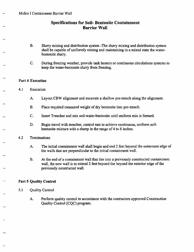
Midco I Containment Barrier Wall
Specifications for Soil- Bentonite ContainmentBarrier Wall
B. Slurry mixing and distribution system -The slurry mixing and distribution systemshall be capable of uniformly mixing and maintaining in a mixed state the water-bentonite slurry.
C. During freezing weather, provide tank heaters or continuous circulations systems tokeep the water-bentonite slurry from freezing.
Part 4 Execution
4.1 Execution
A. Layout CBW alignment and excavate a shallow pre-trench along the alignment.
B. Place required measured weight of dry bentonite into pre-trench.
C. Insert Trencher and mix soil-water-bentonite until uniform mix is formed.
D. Begin travel with trencher, control rate to achieve continuous, uniform soil-bentonite mixture with a slump in the range of 4 to 8 inches.
4.2 Terminations
A. The initial containment wall shall begin and end 2 feet beyond the outermost edge ofthe walls that are perpendicular to the initial containment wall.
B. At the end of a containment wall that ties into a previously constructed containmentwall, the new wall is to extend 2 feet beyond the beyond the exterior edge of thepreviously constructed wall.
Part 5 Quality Control
5.1 Quality Control
A. Perform quality control in accordance with the contractors approved ConstructionQuality Control (CQC) program.
Related Documents