REPORT NO. FAA-FS-600-8 EVALUATION OF £ Approach Procedures for ILS Back Course with Glide Slope Allan W. Hunting SDDC\ July 1972 FINAL REPORT | 2" C Availability is unlimited. Document may be released to Clearinghouse for Scientific and Technical Information, Springfield, Virginia 22151 for sale to the public. NATIONAL TECHNICAL INFORMATION SERVICE U . 'A 22151 DEPARTMENT OF TRANSPORTATION FEDERAL AVIATION ADMINISTRATION Flight Standards Service Washington, D. C. 20591

Welcome message from author
This document is posted to help you gain knowledge. Please leave a comment to let me know what you think about it! Share it to your friends and learn new things together.
Transcript
REPORT NO. FAA-FS-600-8
EVALUATION OF£ Approach Procedures for
ILS Back Coursewith Glide Slope
Allan W. Hunting
SDDC\
July 1972FINAL REPORT | 2"
C
Availability is unlimited. Document may bereleased to Clearinghouse for Scientific andTechnical Information, Springfield, Virginia22151 for sale to the public.
NATIONAL TECHNICALINFORMATION SERVICE
U . 'A 22151
DEPARTMENT OF TRANSPORTATIONFEDERAL AVIATION ADMINISTRATION
Flight Standards ServiceWashington, D. C. 20591
R11f 1 ..............
The contents of this report reflect the findings of theStandards Development Branch, National Flight InspectionDivision, Flight Standards Service, which is responsible forthe facts and the accuracy of the data presented herein. Thecontents do not necessarily reflect the official views orpolicy of the Department of Transportatfon. This report doesnot constitute a standard, specification, or regulation.
TECHNICAL REPORT STANDARD 1ITLE PAGE
I. Roe" Nsi. 2. Government Accession No. 3. Recipient's Ceteleg Ne.
FAA-FS-600-8
4. Title amd SubtitleEvaluation of Approach Procedures for
ILS Back Jl 1972
Course with Glide Slope r . 1972e-- ew, o, Cod.
FS-640
S. Performing Org., setien Report No.
Allan W. Hunting FAA-FS-600-8
9. Performenil Organiat on Nome and Address 10. Worke Unit No.Standards Development Branch, FS-640National Flight Inspection Divison
, I Contact.. G, No.
Box 25082
Oklahoma City, Oklahoma 73125 13. Type of Report end Period Co.erd
12. Sponsoring Agency Nome ond AddressFINAL TECHNICAL REPORT
Department of TransportatioFNWashington, D. C. 20591 no spo ... g Agency Code
• DOT
I. Supplementary Notes
I& AbstractAn operational evaluation was performed to compare ILS back course approacheswith front course approaches in an effort to determine flyability problems
t associated with back course ILS with glide slope and the appropriate obstacleclearances to be applied. 32 simulated approaches were flown in the B720flight simulator. 63 hooded approaches were flown in 6 different aircraft.Facility and airborne systems included Back and Front courses; Localizer onLyand Localizer with Glide Slope; Normal and Reverse course sensing; and all wereflown using raw ILS data for guidance. A questionnaire was filled out on eachsubject pilot at the end of his runs. Heights above touchdown at which IlSguidance became unusable were computed from simulator tracings and data logs.It was found that the established ILS obstacle clearance criteria for frontcourse ILS approaLhes with glide slope is adequate for back course approacheswith glide slope.
Details of illustrations ithis document may be better
studied oil microfiche
17. Key Words 18. Distribution StatementILS ApproachesInstrument rrocedures Distribution UnlimitedApproach Procedures
Precis ion ApproachBack Course Approach
19. Security Clossf. (of this report) 20. Scurity ClassiI (of this page) 21. No. of Pages 72. Price
Unclassified Unclassified 34
Farm DOT F 1700.7 (6.69)ii
CONTENTS
Abstract ................................................. Page iIntroduction ................................. ................ ivStatement of the Problem ...................................... 1Objectives .................................................... !Test Methods .................................................. 2Data Collection ............................................... 8Data Reduction and Analysis .................................. 11Findings ..................................................... 2
LIST OF FIGURES,
ILS Course Comparisons ..............................Page 3
2. ILS BC Procedure - Chickasha ............................. 43. ILS Course Comparisons ................................... 54. ILS Glide Slope Comparisons .............................. 65. Tabulation of Data ....................................... 06. B720 Simulator Composite. LOC/GS. Raw Data ............ 127. B720 Simulator Composite. LOC/GS. Paw Data ............ 138. B720 Simulator Composite. LOC. BC. Raw. Reverse.....l549. B720 SiTijator Composite. LOC. BC. Raw. Normal ...... 1510. B720 Sir *tor Composite. LOC/GS. BC. Raw. Reverse..1611. B720 Simu" ;:, Composite. LOC/GS. BC. Raw. Reverse..1712. B720 Simulator Composite. LOC/GS. BC. Raw. Normal...1813. B720 Sirtulator Composite. LOC/JS. BC. Raw. Normal ...1914. B720 Siauiator Tabulation ............................... 2015. Flight Jata Scatter Plots. LOC. BC .................... 22"16. Flight Data Scatter Plots. LOC/GS. BC ................. 23i7. Flight Data Tabulation .................................. 24
li
Project Report on Evaluation of Approach Procedures for ILS
Back Course with Glide Slope.
Project Officer Allan W. HuntingChief, NavigationSystems EvaluationSection
Concur E. E. CallawayChief, StandardsDevelopment Branch
ApprovedChief, National
Flight InspectionDivis on
Released Figecr,)Flight StandardsService
July 1972
ii
INTRODUCTION
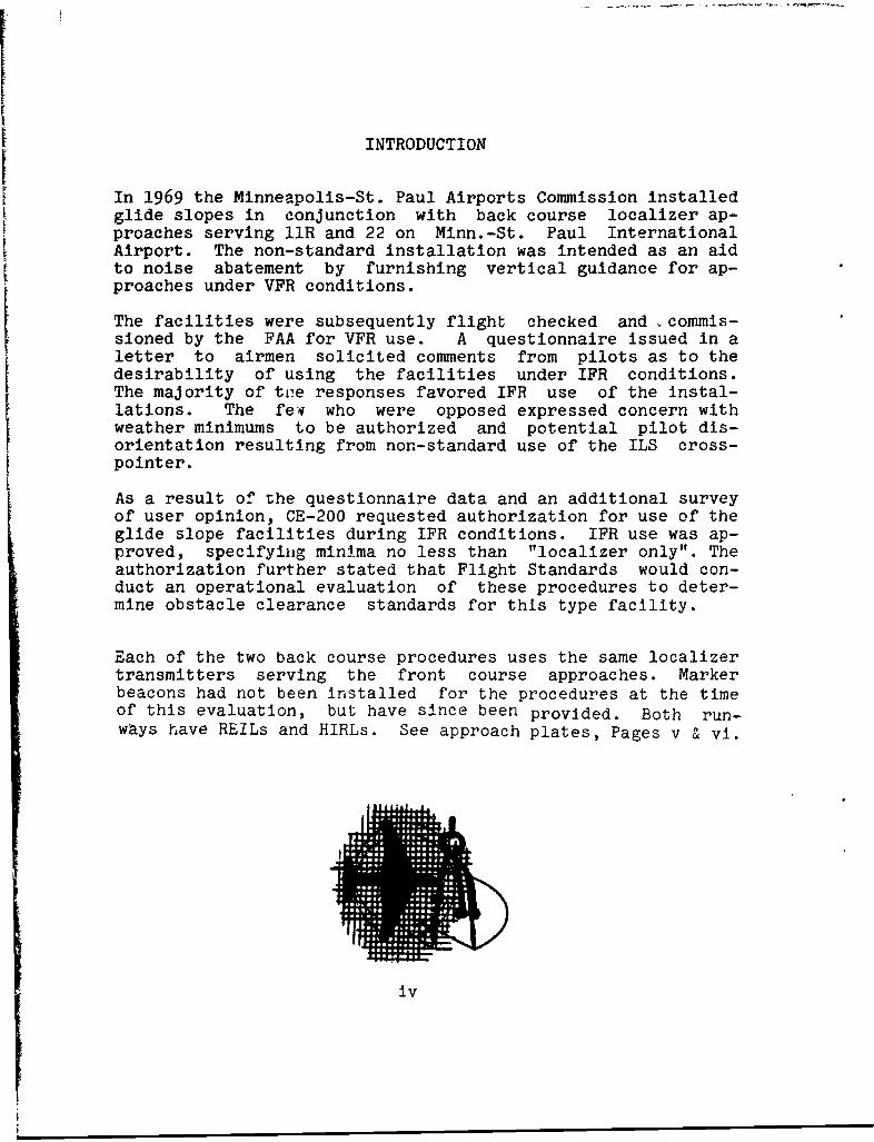
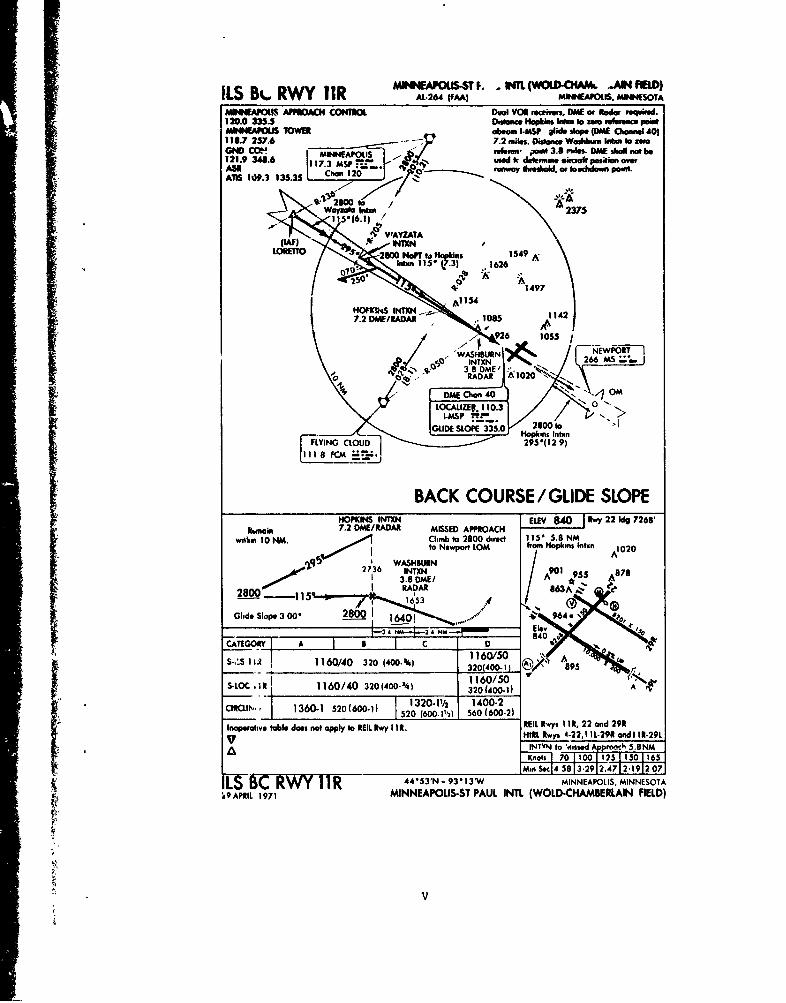
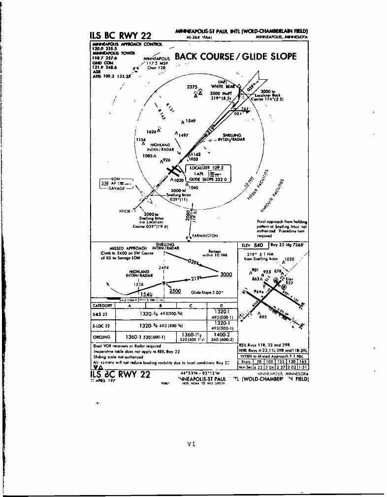
In 1969 the Minneapolis-St. Paul Airports Commission installedglide slopes in conjunction with back course localizer ap-proaches serving llR and 22 on Minn.-St. Paul InternationalAirport. The non-standard installation was intended as an aidto noise abatement by furnishing vertical guidance for ap-proaches under VFR conditions.
The facilities were subsequently flight checked and --commis-sioned by the FAA for VFR use. A questionnaire issued in aletter to airmen solicited comments from pilots as to thedesirability of using the facilities under IFR conditions.The majority of toe responses favored IFR use of the instal-lations. The fev who were opposed expressed concern withweather minimums to be authorized and potential pilot dis-orientation resulting from non-standard use of the ILS cross-pointer.
As a result of the questionnaire data and an additional surveyof user opinion, CE-200 requested authorization for use of theglide slope facilities during IFR conditions. IFR use was ap-proved, specifying minima no less than "localizer only". Theauthorization further stated that Flight Standards would con-duct an operational evaluation of these procedures to deter-mine obstacle clearance standards for this type facility.
Each of the two back course procedures uses the same localizertransmitters serving the front course approaches. Markerbeacons had not been installed for the procedures at the timeof this evaluation, but have since been provided. Both run-ways have REILs and HIRLs. See approach plates, Pages v & vi.
iv
I LS B4.. RWY 11R AL24JAJM104EAPOLM *4ESCITA
MINNIAPOLIS AfhROAO COMMO Dual VON reciver DAAE or Radar eqi..120.0 335.5 Duiscef hopkins wan. to zero PointeeMINIIAPOUS TOWER ab Am -SP alid. slope (DatE O110111e.01140110I.7 257.6 7.2 miles. Distance Wasiban labs to zeroGMe COeM ME4NNEAPOLIS - mfe,.s, point 3.8 n-des. DatE shall not be121.9 348.6 us7.3 Mo ~ I r "nmine eiaol pasdsa over
AM lop1..) 135.351 C.,_S 120 a-. . usna)' Uwiald. as auctddo poolt.
waysoa bibi, A2375
1b1
HOPKS INT DIV 8A0 1542 d 728
Beaa~n7.2 DI/RADA MI1D42UOC
2736 I.926~ 105
qj 3. 8ME A E'" 'A87 8
1653A 2 1020
DIKE4 Chan 40 O
5-LOC ~ ~ ~ LCAIZR 11 104 2(401)3040.) 0v
520 60I2 56PE0 60002)I. ~~~ FYN C Hoic. Iy .2, 1.9 ad 1.9
HOPKNS fINTNLE to Rigwe A 2 rot 728M
within~~~Kot 10 10' Cl25 to0 165dret 15*58
jq q w -- ,'M n~ e t58 3.29or 2.47 2.19 H p i s nt 20 7
4 ~ ~ ~ ~ ~ ~ 23 WASHBUN-933WMNEPIMINSA~~~s9 ~ ~ ~ .APRIL 1971 9INNP IST PAL87L(ODCHMELINFED
280RDA
-1 1q 161 5 863
M**PU-T PAUL WTL (WW34M A FMr)ILS BC RWY 22 AL-264 'FAA) MINNEAPOLIS, MINNESOTA
- APPROACH CONnIM120.0 335.3
7 257.6 o M BACK COURSE / GLIDE SLOPEGN CO Z117 3 MSP
121.9 348.6 Chon 120
ATIS 109.3 135.30.. (UAF)
""2 3 7 5 ,., W H IT E3 0 0 t25 N Locoh er Sack
2192(8.5) -Fou r 174(2 5)
/ ~A 1549""\
1626NE AN1497 SNELLING11MS 4 AR E=LEN/ 8 dAR
HIGHLAND I29IINTXN /ARA3AR000
1085A 142v
Lo25zE 109 3 .\ ~I-APL "*m I -'
CT -LOA02Y D E S SLO E 3320"1338 AP '=--. A -'( A. -1 A rct,_ -----SAVAGE 1060___ 493(000'16 /i 89
3000-1 7
'rC - " S ne l l i g Intx"
/ , tvq"
5-LO 23 493,(11) 4(0 op. A
Snelhngc 0nt, O_ -
C a 1 0 IzeIr f 1inal approach from holding
Course 039"(I 9 61 pattern of Snellhng Intxn n1ot
/a 2uthorized Procedure turnRMING7Na requiredRd
SNELLING ELEV 840 1 IL. 22 Idg 72681MISSED APPROACH INTXN/RADAR
Climb to 2400 on SW Course ibt Re yn Knot9*70 1 N 2 Iof ILS to Savage LOM / ODwt~ 0N from Snellhng lIhtxn A1 020 /
HIGHLAND 42 30 2INTXN1 RADAR I-A 300 83 l€Ee
1538 (0) 27...... . 12500 GI id*eSlope3 00" . , 964N,4
.54LS 22 /v |320-/4 493(5- N 1320-1 . AME S493 (500-1 l 895
1320-1 S' iiSLOC 22 j 1320-3/4 493 (500-N 493(500-1)ACIRCLING
j 1360-1 520(600-1) 1360-11,2 1400-21 520 (600 1'3) 560(600-2)
Dual VOR receivers or Radar required REIL Rwys I I R, 22 and 29R
Inopertive table does not apply to REIL Rwy 22 HIARI.w~ys 4-2 2,11 L-29R andlII R-29L
Sliding scale not authorized -INTXN to Missed Approach 5 1 NK,
Air rcomers will not reduce landing visibillity due to local conditions Rwy 22 Knots I I0 I0 1 1 0 165
.... MnSc42 1 4 2 2712 02 11.51
ILS 8C RWY 22 44'53'N -93 *13'W ',AINNEAPOIS MINNESOTA
3," APRL 197 NNEAPOLIS.ST PAUL ' 'TL (WOLD-CHAMBER' N FIELD)APRL 97lm, NOS NOAA TO 1ACC SIECIFI
STATEMENT OF THE PROBLEM
The non-standard ILS back course system involves flyabilityproblems not experienced on the front course because of two
factors:
1. The cross-pointer on the ILS indicator presents"normal" glide slope sensing and "reverse" localizersensing, except in aircraft equipped with FlightDirector Systems or localizer sensing switch capa-bility. Simultaneously flying toward the glideslope needle but away from the localizer needle re-quires an abnormal interpretation of the ILS indica-tor.
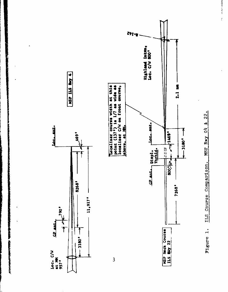
2. Use of the front course localizer antenna for theback course approach results in a "squeezed" back-course, approximately 14% as wide as the frontcourse at comparable distances from the approachends of the runways.
At some point during the final approach, flyability can be ex-pected to deteriorate as the pilot copes with both "abnormal"instrument interpretation and increased CDI sensitivity. Dataare needed to develop obstacle clearance standards and identi-fy the point at which the system is unflyable and the pilotshould pick up visual cues to complete the approach.
OBJECTIVES
1. Identify and evaluate flyability problems on a backcourse approach with a glide slope.
2. Determine the point at which the electronic guidanceis no longer usable (flyable).
3. Establish obstacle clearance criteria for the ILSback course approach with glide slope.
TEST METHODS
Simulator Phase. The simulator phase was designed to evaluateflyability problems under all possible combinations of facil-ity guidance and receiver modes and to identify a tentativelyacceptable decision height for evaluation during the flightphase.
The Boeing 707 simulator was used to record localizer andglide slope tracks on simulated approaches to Minn.-St. Paulrwy 4 (front course ILS) and rwy 22 (back course ILS wiglide slope). See Figure 1, Page 3.
The approaches were flown as published except that all ap-proaches were simulated to a decision height of 100'. This DHtested the following assumption:
If the flyability of a back course with glide slope isacceptable, both localizer and glide slope must provideusable precision guidance to an authorized decisionheight. (Precision guidance was considered unusablewith full scale deflection of either cross-pointerneedle or needle movement too rapid for normal correc-tion technique to follow.)
Simulator subjects were seven FAA Air Carrier instructorpilots, qualified and current in the Boeing-720, as well asone additional pilot with only familiarization training in theaircraft.
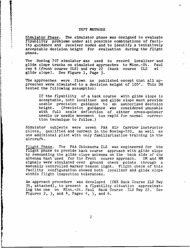
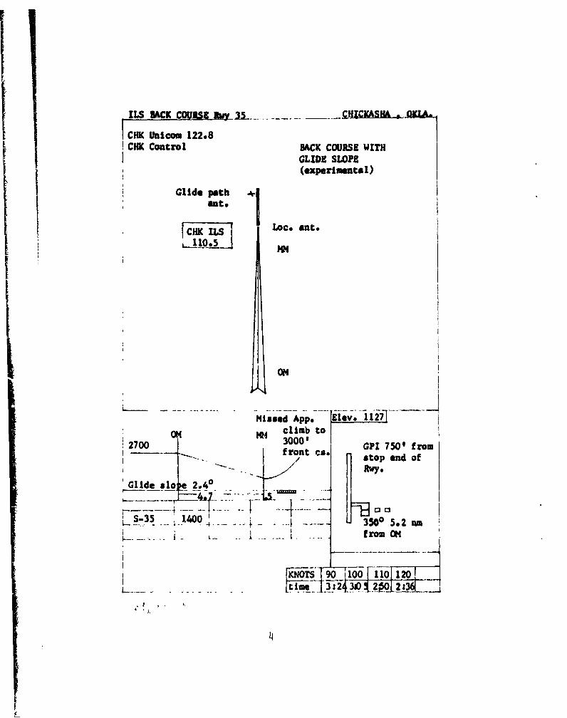
Flight Phase. The FAA Chickasha ILS was engineered for theflight phase to provide back course approach with glide slopeby remounting the glide slope antenna on the back side of theantenna mast used for the front course approach. OM and MMsignals were simulated over ground check points through amanually controlled marker beacon light. Flight check of thisfacility configuration showed both localizer and glide slopewithin flight inspection tolerances.
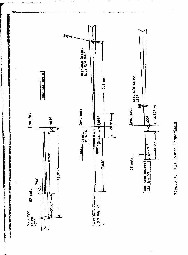
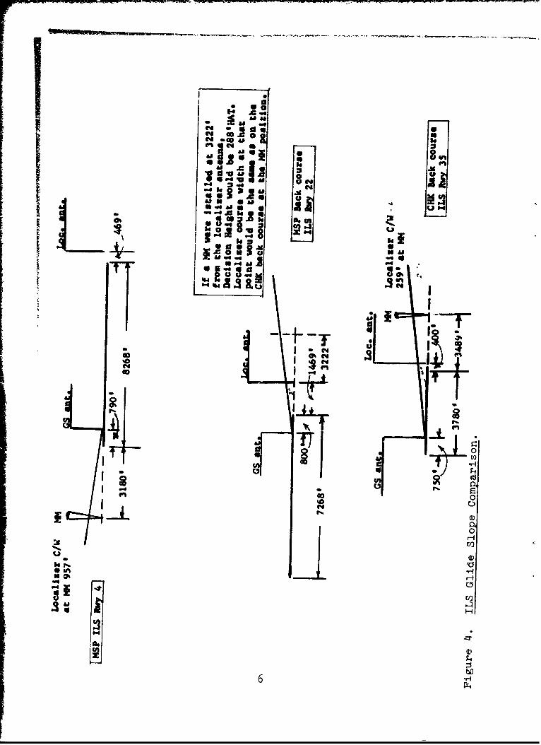
An approach procedure was developed (CHK Back Course ILS Rwy35, attached), to present a flyability situation approximat-ing the one on Minn.-St. Paul Back Course ILS Rwy 22. SeeFigures 2, 3, and 4, Pages 4, 5, and 6.
2
oo
I.
iso
W4 "4
66.. X
.06
416k"%D2 0
.064
00
600
C4 :
I,- -id
TI h~iEn'0 6.(n
ILS MACK COURSE hey 33- C"iuCKAisi OIA.
ICHIK Inicom 122.8CHK Control BACK COURSE WITH
GLIDE SLOPE(experimental)
Glide aottht.
_fICHE ILS [ LOCO At.
ON
-Missed _App.__ji Iv 117j_ _
0O4 K4 climb to
2700 3000' GPI 750 from--- * f ront ca. a.top end of
Glide al ae 2.40... ..--- -- - - r ..
S-35 1400 .35.00 s.2 m
Sfrom oN
KNOT 9 i-90 10 11120i 3:2j30 02s
4 .4U0
a Vl
.4 F4
UU
11if I ..: C 1
"-4-5~Ip
00
S o
aa
£ 1I11
.4 -4 IU 8 m.
k .
-
9 Jul
ww
C4
InI
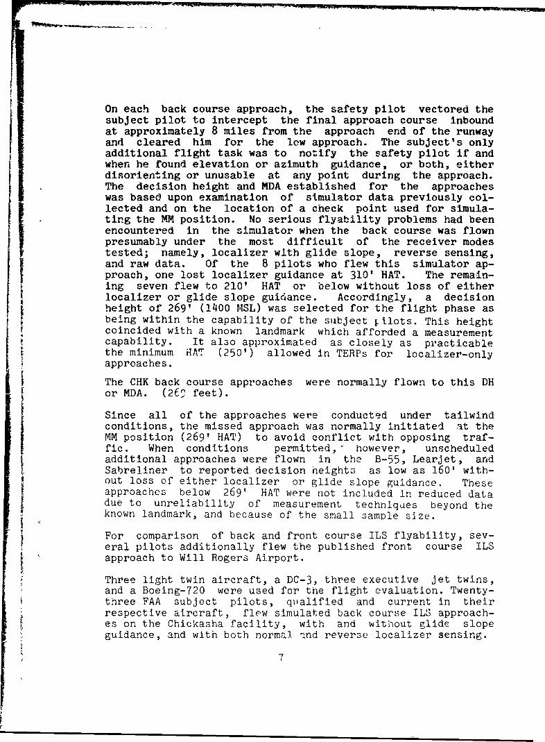
On each back course approach, the safety pilot vectored thesubject pilot to intercept the final approach course inboundat approximately 8 miles from the approach end of the runwayand cleared him for the low approach. The subject's onlyadditional flight task was to notify the safety pilot if andwhen he found elevation or azimuth guidance, or both, eitherdisorienting or unusable at any point during the approach.The decision height and MDA established for the approacheswas based upon examination of simulator data previously col-lected and on the location of a check point used for simula-ting the MM position. No serious flyability problems had beenencountered in the simulator when the back course was flownpresumably under the most difficult of the receiver modestested; namely, localizer with glide slope, reverse sensing,and raw data. Of the 8 pilots who flew this simulator ap-proach, one lost localizer guidance at 310' HAT. The remain-ing seven flew to 210' HAT or below without loss of eitherlocalizer or glide slope guidance. Accordingly, a decisionheight of 269' (1400 MSL) was selected for the flight phase asbeing within the capability of the subject Iilots. This heightcoincided with a known landmark which afforded a measurementcapability. It also approximated as closely as practicablethe minimum HAT (250') allowed in TERPs for localizer-onlyapproaches.
The CHK back course approaches were normally flown to this DHor MDA. (260 feet).
Since all of the approaches were conducted under tailwind
conditions, the missed approach was normally initiated at theMM position (269' HAT) to avoid conflict with opposing traf-fic. When conditions permitted, however, unscheduledadditional approaches were flown in the B-55, Learjet, andSabreliner to reported decision heights as low as 160' with-out loss of either localizer or glide slope guidance. Theseapproaches below 269' HAT were not included in reduced datadue to unreliability of measurement techniques beyond theknown landmark, and because of the small sample size.
For comparison of back and front course ILS flyability, sev-eral pilots additionally flew the published front course iLSapproach to Will Rogers Airport.
Three light twin aircraft, a DC-3, three executive jet twins,and a Boeing-720 were used for the flight evaluation. Twenty-three FAA subject pilots, qualified and current in theirrespective aircraft, flew simulated back course ILS approach-es on the Chickasha facility, with and wltiout glide slopeguidance, and with both normal ind reverse localizer sensing.
7
DATA COLLECTION
Simulator Phase (Boeing-707)
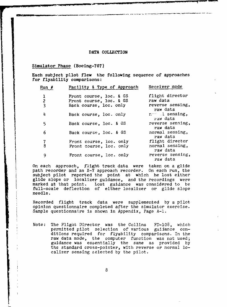
Each subject pilot flew the following sequence of approaches
for flyability comparisons:
Run # Facility & Type of Approach Receiver mode
I Front course, loc. & GS flight director2 Front course, loc. & GS raw data3 Back course, loc. only reverse sensing,
raw data4 Back course, loc. only n - -1 sensing,
.aw data
5 Back course, loc. & GS reverse sensing,raw data
6 Back course, loc. & GS normal sensing,raw data
7 Front course, loc. only flight director8 Front course, loc. only normal sensing,
raw data9 Front course, loc. only reverse sensing,
raw data
On each approach, flight track data were taken on a glidepath recorder and an X-Y approach recorder. On each run, thesubject pilot reported the point at which he lost eitherglide slope or localizer guidance, and the recordings weremarked at that point. Lost guidance was considered to befull-scale deflection of either localizer or glide slopeneedle.
Recorded flight track data were supplemented by a pilotopinion questionnaire completed after the simulator exercise.Sample questionnatre is shown in Appendix, Page A-1.
Note: The Flight Director was the Collins FD-108, whichpermitted pilot selection of various guilance con-ditions required for flyability comparisons. In theraw data mode, the computer function was not used;guidance was essentially the same as provided bythe standard cross-pointer, with reverse or normal lo-calizer sensing selected by the pilot.
8
Flight Phase
Each subject pilot flew a "localizer only" approach and threelocalizer with glide slope approaches on the Chickasha backcourse ILS. On the DC-3 runs, azimuth, elevation, and rangedata were collected on flight inspection Century recorders.In the Light Twin and Executive Jet aircraft, the subjectpilots' instrument panels were photographed at 5 second in-
tervals during the approaches. On all Chickasha approaches,the project engineer recorded the altimeter reading when thesubject pilot reported loss of either glide slope or local-izer guidance. Runs flown on the published front course ap-proach to Will Rogers World Airport were not recorded, norwere the runs flown in the Boeing 720.
Flyability of the back course ILS with glide slope had
already been evaluated in the Boelng-707 simula~cr. The
flight evaluation was conducted to check the points in heavyjet aircraft where navigational guidance would be lost.
The tabulation on the following page shows the aircraft, num-ber of subject pilots, and navigational guidance used duringthe flight phase of the project.
Subject pilots completed the same questionnaire used duringthe simulator phase. (See Appendix, Page A-1)
it0
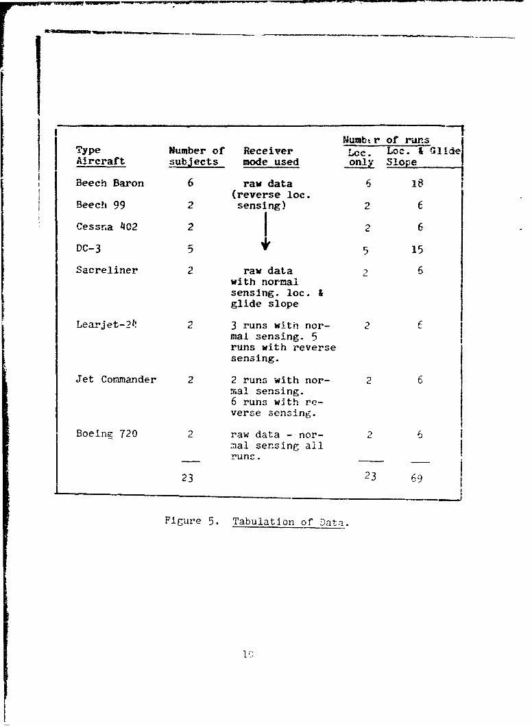
Uumbtr of runsType Number of Receiver Lcc. Loc. & GlideAircraft subjects mode used only Slope
Beech Baron 6 raw data 6(reverse loc.
Beech 99 2 sensing) 2 6
Cessna 402 2 2 6
DC-3 5 * 5 15
Sacreliner 2 raw data 2 6with normalsensing. loc.&glide slope
Learjet-211 2 3 runs with nor- 2mal sensing. 5
runs with reversesensing.
Jet Commander 2 2 runs with nor- 2 6mal sensing.6 runs with re-
verse sensing.
Boeing 720 2 raw data - nor- 2 6mal sensing allruns.
23 23 69
Figure 5. Tabulation of Data.
1 Q
DATA REDUCTION AND ANALYSIS
Simulator Phase
Azimuth and elevation recordings fro, the nine types of simu-lator a proaches were examined for evidence of flyabilityproblems. Regardless of the receiver mode used on the fivefront course approaches, none of the six pilots type rated inthe B-720 reported unusual flyability problems. Runs flownwith flight director guidance were most accurate,as expected,since this mode is normally used by the subject pilot group.The last two of the nine runs scheduled for each subject werefront course "localizer only" approaches, with raw dataguidance. Selection of reverse localizer sensing had noapparent effect on the flyability of the front course, due tocuing inherent in the test situation and to practice duringprevious runs.
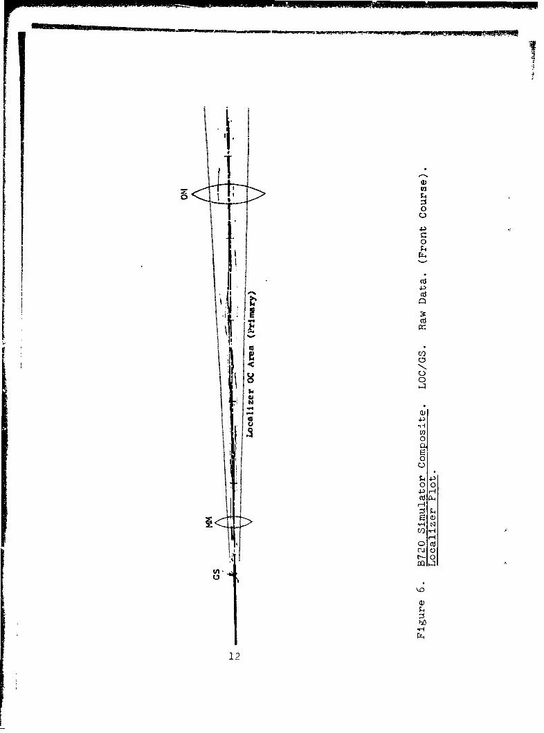
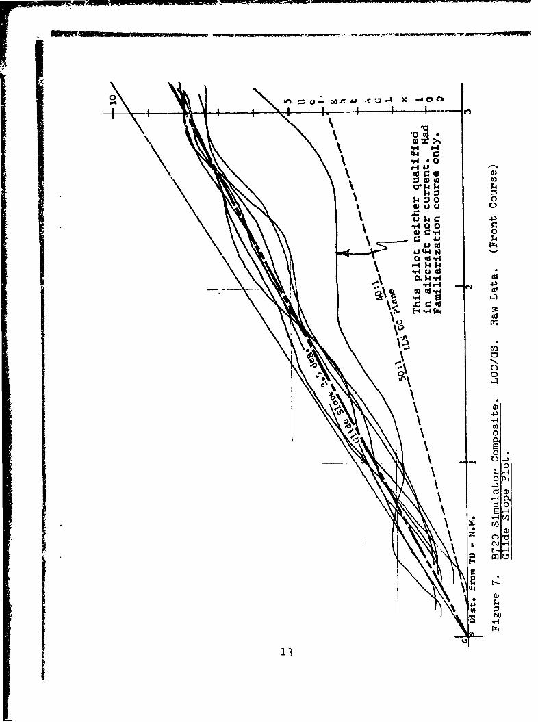
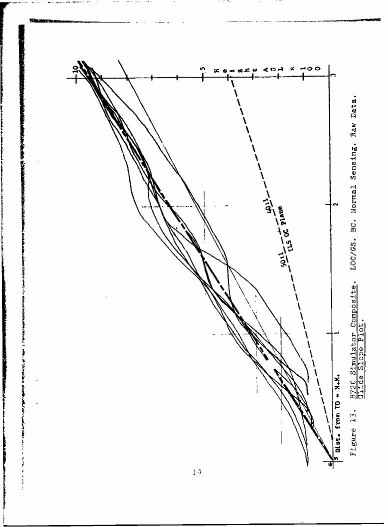
Composites of each type of back course approach and of onefront course approach were produced from the simulator re-cordings to show azimuth and elevation comparisons under thefollowing guidance conditions: (See Pages 12 through 19)
Front course, localizer & glide slope, raw data.IBack course, localizer only, reverse sensing, raw data.
Back course, localizer only, normal sensing, raw data.
Back course, loc. & glide slope, reverse sensing, rawdata.
Back course, loc. & glide slope, normal sensing, rawdata.
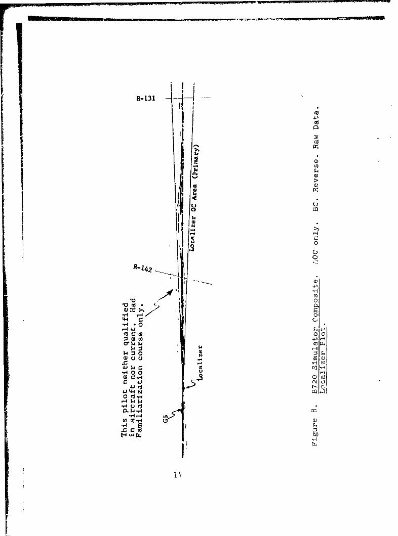
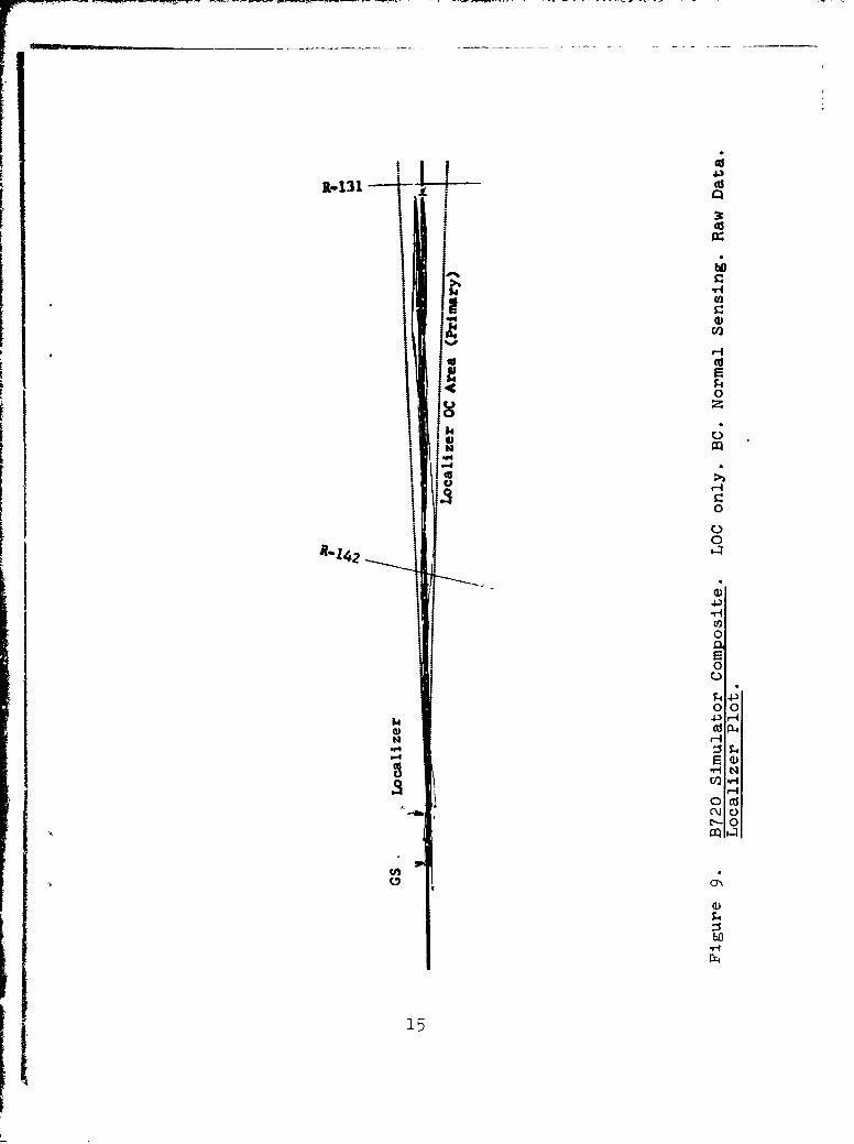
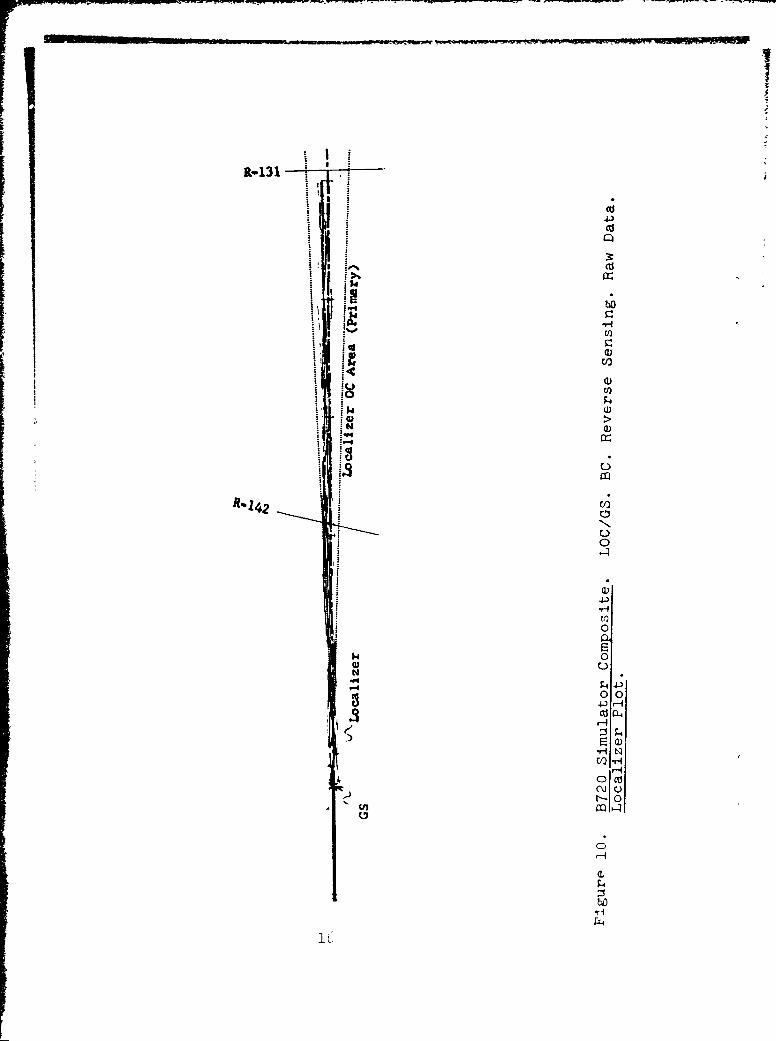
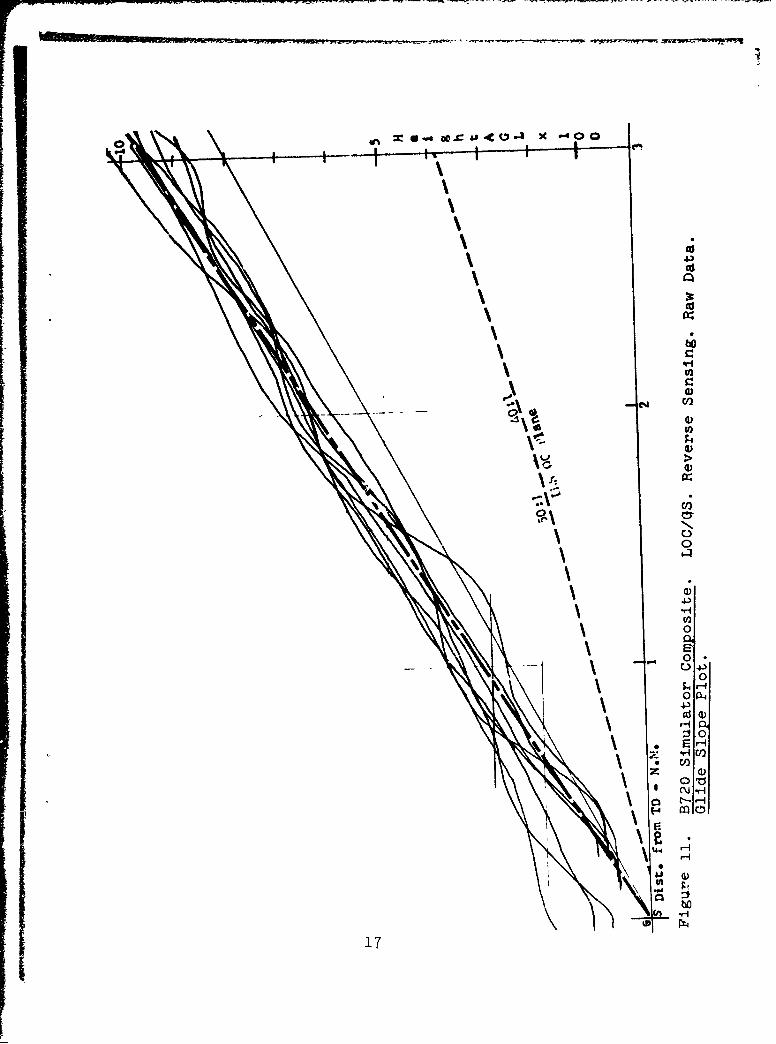
Comparisons of flight tracks of "localizer only" approaches,Fig. 8, 9, 10, & 11, reflect initial problems with reversesensing, probably due to the fact that th-.s mode is an ab-normal use of the Integrated Flight System, customarily flownwith normal sensing on both front and back course approaches.Following a practice "localizer only" run with reversesensing, the approach reported as the most difficult (backcourse with glide slope, reverse sensing) was flown with no
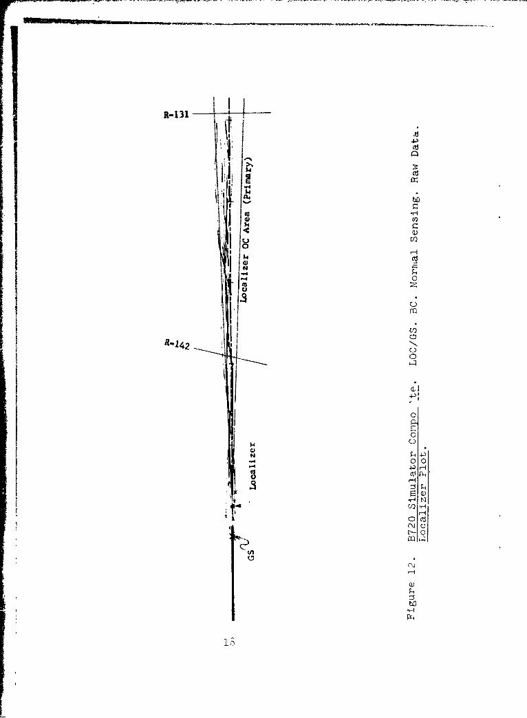
4serious flyability problem as compared with the other ap-proaches. See flight track composites, Figs. 12 and 13.
For each of the back course approaches flown under four dif-ferent guidance conditions, the points were identified on therecorder plots where usable guidance was lost. Guidance usa-ble to 100' HAT was recorded as no loss of guidance. Fig. 14is a tabulation of usable guidance data for the 32 backcourse approaches. Localizer guidance vas lost before glides1ope guiance nn all approaches but one. On 8 of the 14 ap-proaches with glide slope, flown by qualified and current pi-lots, guidance was usable to 100' DH. Guidance was usable toan average HAT of 147', with reverse localizer sensing, andto an average HAT of 143', with normal sensing.
11
41 N4
cri
00
00C
12
u wx f u 4 x 4 0 0
'44 0
-A 0
$44
$4k
-A 0
44.
CA 0
0.
0
0 4)
13-
or P N19
R-131 -
NN'I1
0%
i" °iIw >
V-4 "tv0 0 0
N
4 H
-H 0 0
oo Cf
N0
-W 4-
0 040t-4$4142
-P4 U o '
4I WI
•r4 C--I
14 c.
t-44J.2I(Tcl
R-131I
ca
4$S0
0.
IC-)
0
R1Rj420
I.:
0
S4.) ,
00
C.)
co 4.)
0
14P1H
R-131
a>0 0
[,I-I
co
CC
,
o~ .64OA4 VI Co -C sOC
4,
US
l
N. cil
(L)
U 4.
00 L
4-)
:30
04-
17
- -,
R-131 i '
oo
it
• r
H' K
R-142
t C)
~0
4-)
0 0
0
0
18°
• .-,0
-,'
C
0
H C)0)-
Cu
CI
.1-fU,
l
0
0 0
rIa,1r 00COP
0 a)v
1 29
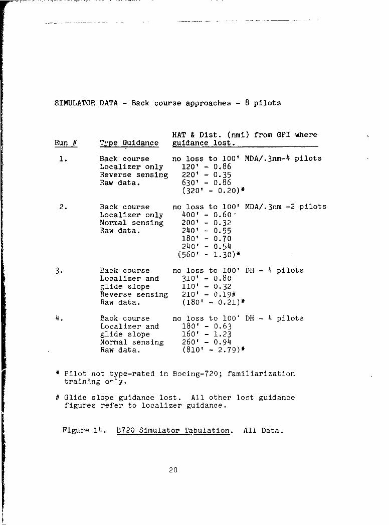
SIMULATOR DATA - Back course approaches - 8 pilots
HAT & Dist. (nmi) from GPI whereRun # Type Guidance guidance lost.
1. Back course no loss to 100' MDA/.3nm-4 pilotsLocalizer only 120' - 0.86Reverse sensing 220? - 0.35Raw data. 630' - 0.86
(320' - 0.20)*
2. Back course no loss to 100' MDA/.3nm -2 pilotsLocalizer only 400' - 0.60"Normal sensing 200' - 0.32Raw data. 240' - 0.55
180' - 0.70240' - 0.54(560' - 1.30)*
3. Back course no loss to 100' DH - 4 pilotsLocalizer and 310' - 0.80glide slope 110' - 0.32Reverse sensing 210' - 0.19#Raw data. (180' - 0.21)*
4. Back course no loss to 100" DH - 4 pilotsLocalizer and 180' - 0.63glide slope 160' - 1.23Normal sensing 260' - 0.94Raw data. (810' - 2.79)*
; Pilot not type-rated in Boeing-720; familiarizationtraining o--y.
# Glide slope guidance lost. All other lost guidancefigures refer to localizer guidance.
Figure 14. B720 Simulator Tabulation. All Data.
20
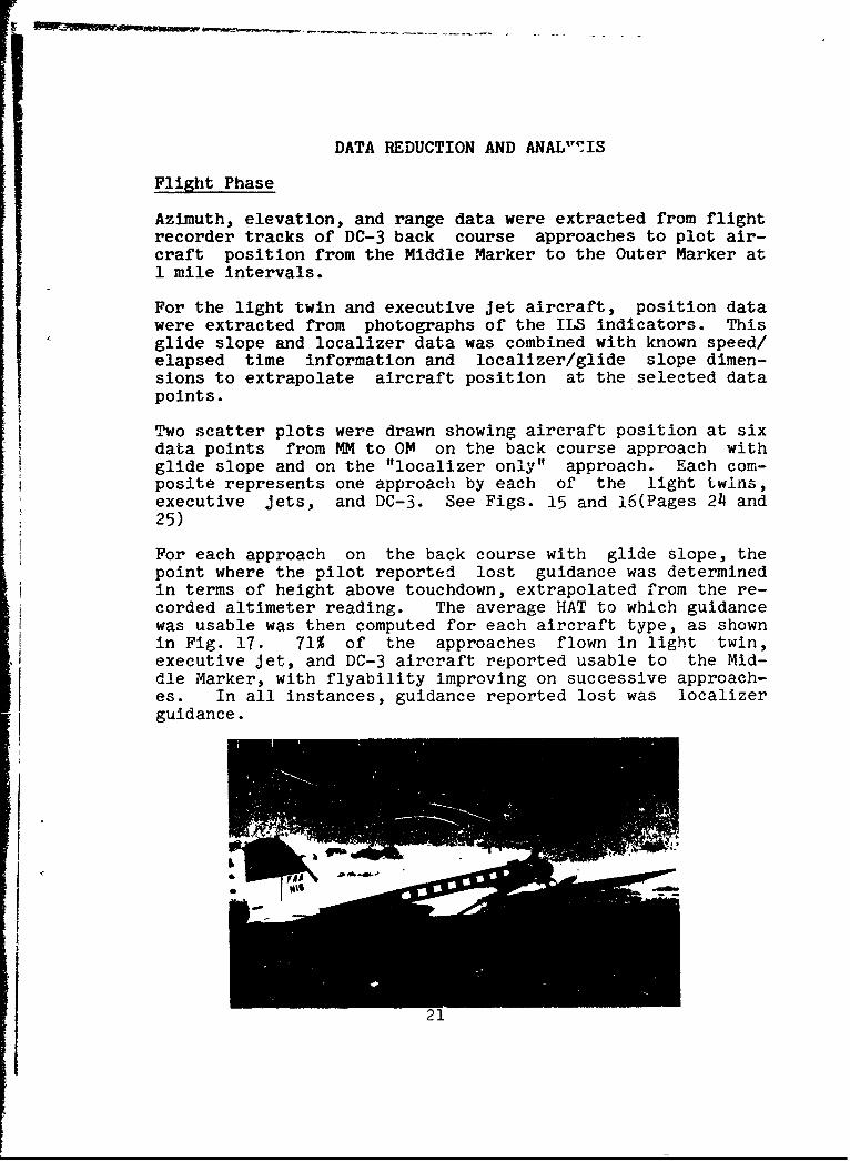
DATA REDUCTION AND ANAL"7IS
Flight Phase
Azimuth, elevation, and range data were extracted from flightrecorder tracks of DC-3 back course approaches to plot air-craft position from the Middle Marker to the Outer Marker at1 mile intervals.
For the light twin and executive jet aircraft, position datawere extracted from photographs of the ILS indicators. Thisglide slope and localizer data was combined with known speed/elapsed time information and localizer/glide slope dimen-sions to extrapolate aircraft position at the selected datapoints.
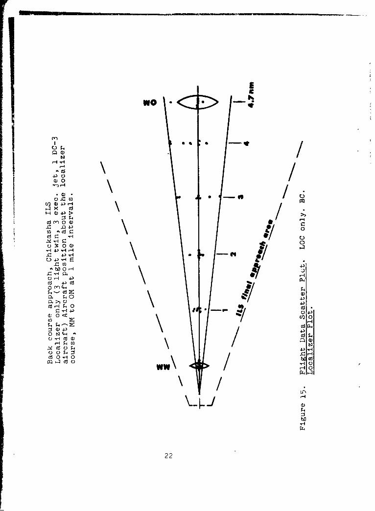
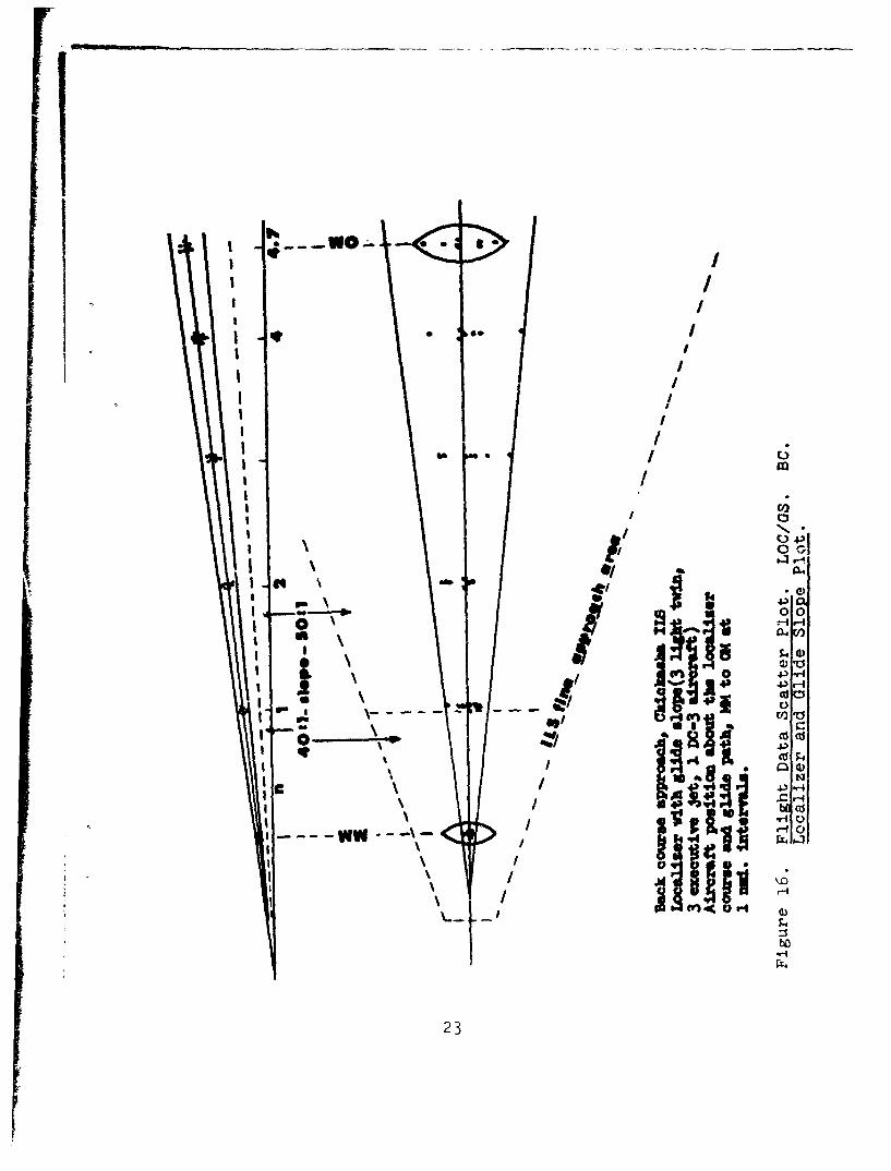
Two scatter plots were drawn showing aircraft position at six
data points from MM to OM on the back course approach with
glide slope and on the "localizer only" approach. Each com-posite represents one approach by each of the light twins,executive jets, and DC-3. See Figs. 15 and 16(Pages 24 and25)
For each approach on the back course with glide slope, thepoint where the pilot reported lost guidance was determinedin terms of height above touchdown, extrapolated from the re-corded altimeter reading. The average HAT to which guidancewas usable was then computed for each aircraft type, as shownin Fig. 17. 71% of the approaches flown in light twin,executive jet, and DC-3 aircraft reported usable to the Mid-dle Marker, with flyability improving on successive approach-es. In all instances, guidance reported lost was localizerguidance.
21
E
4, 0S S-
0
0 .). 0 Ic(1) .4-' >/
cri z 00-Y5 -H 0
4-1 4 ) * r-r- 4-3 HErij~0c 4-)-r
C : 4-) 4-o0 -i i
0) 0 04-
0 l) C I H
4 0)44.0Cd r4 I c
r- H 4-3 C) I -3
o N- 4C. l cd a)
Cd OH0 SL W~
Cd 0 0 / H
bfl-H
22
.0 0sII
IL 0 11.2 42 43 r-a 4P Cd
HI C Cl3
941
4.00
M-K 4 4
"'W
23V
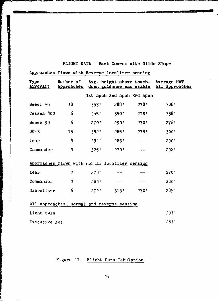
FLIGHT DATA - Back Course with Glide Slope
Approaches flown with Reverse localizer sensing
Type Nuumber of Avg. height above touch- Average HATaircraft approaches dowr guidance was usable all approaches
1st apch 2nd apch 3rd apch
Beec- '5 !8 353' 288' 278' 306'
Cessna 402 6 ;-5' 350' 270' 338'
Beech 99 6 270' 290' 270' 278'
DC-3 15 342' 285' 274' 300'
Lear 1 294" 285' -- 290'
Commander 4 325' 270' -- 298'
Approaches flown with normal localizer sensing
Lear 2 270' .... 270'
Commander 2 280' .... 280'
Sabreliner 6 270' 315' 270' 285'
All approaches, normal and reverse sensing
Light twin 307'
Executive jet 287'
Figure 17. Flight Data Tabulation.
24
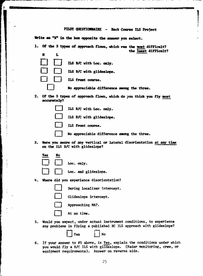
PILOT QUESTIOnAI - Back Course ILS Project
Write an "r in the box opposite the anuwer you select.
1. Of the 3 types of approach flown, which vas the most difficult?
the least difficult?L
nI 0--I 1LS B/C with Loc. only.
El 0 n S B/C with glideslope.
El 0 nS front course.
11 No appreciable difference among the three.
2. of the 3 types of avproach flown, which do you think you fly most
[I]ILS B/C with Loc.- only.
L.J 1. B/C with glideslope.
E I S. front course.
[] No appreciable difference among the three.
3. were you aware of any vertical or lateral disorientation at any timeon the ILS B/C with glideslope?
Yes No
[] [0 Loc. only.
Ii] [I]Loc. and glideslope.4. Where did you experience disorientation?
E] During localizer intercept.
L]1 Glideslope irtercept.
E- Approaching MAP.
[ At no time.
5. Would you expect, under actual instrument conditions, to experienceany problems in flying a published BC ILS approach with glideslope?
fl Yes fl No
6. If your answer to #5 above, is Yes, explain the conditions under whichyou would fly a B/C ILS with glideslope. (Radar monitoring, crew, orequipment requirements). Answer on reverse side.
25
?u
II
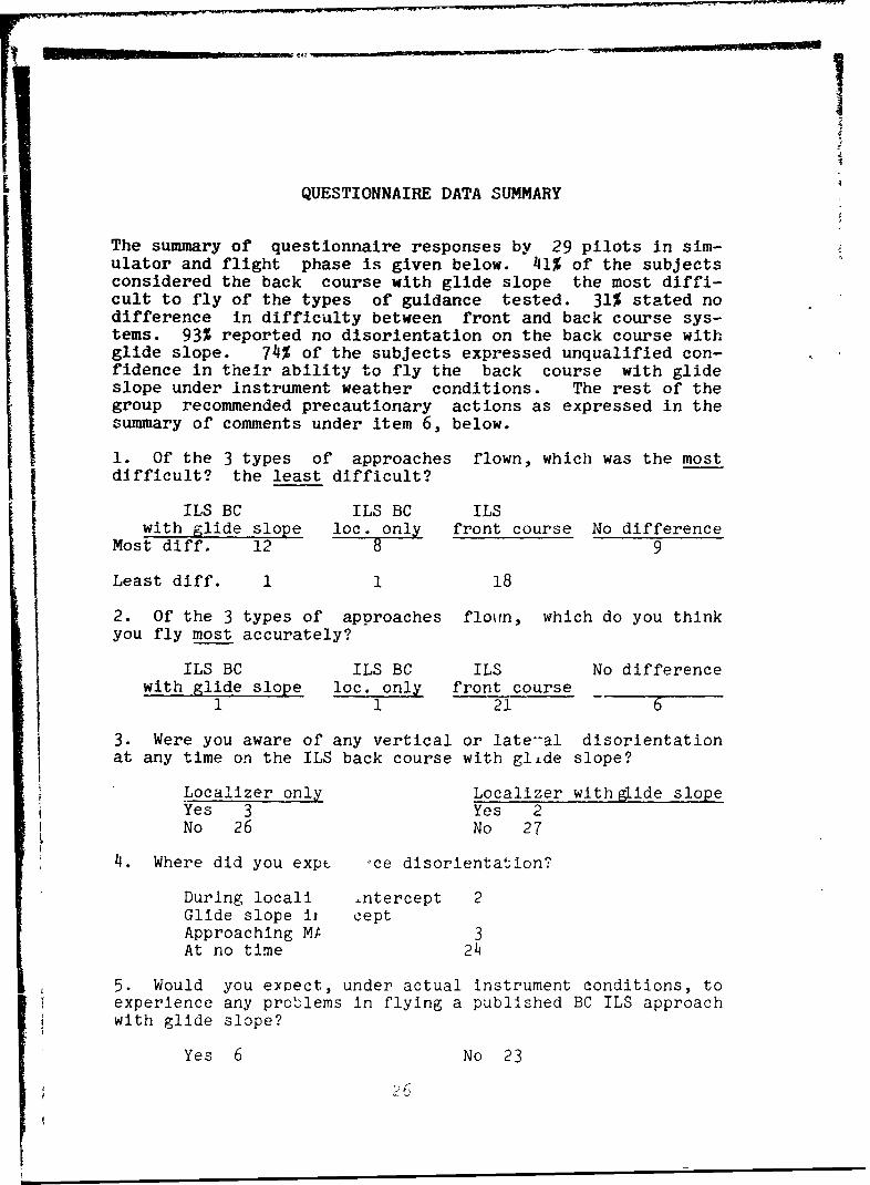
QUESTIONNAIRE DATA SUMMARY
The summary of questionnaire responses by 29 pilots In sim-ulator and flight phase is given below. 41% of the subjectsconsidered the back course with glide slope the most diffi-cult to fly of the types of guidance tested. 31% stated nodifference in difficulty between front and back course sys-tems. 93% reported no disorientation on the back course withglide slope. 74% of the subjects expressed unqualified con-fidence in their ability to fly the back course with glideslope under instrument weather conditions. The rest of thegroup recommended precautionary actions as expressed in thesummary of comments under item 6, below.
1. Of the 3 types of approaches flown, which was the mostj difficult? the least difficult?
ILS BC ILS BC ILSwith glide slope loc. only front course No difference
Most diff. 12 8 9
Least diff. 1 1 18
2. Of the 3 types of approaches flown, which do you thinkyou fly most accurately?
ILS BC ILS BC ILS No differencewith glide slope loc. only front course
1 1 21 6
3. Were you aware of any vertical or late-al disorientationat any time on the ILS back course with glLde slope?
Localizer only Localizer with glide slopeYes 3 Yes 2No 26 No 27
4. Where did you expt "ce disorientation?
During locali ntercept 2Glide slope ii ceptApproaching MP 3At no time 24
5. Would you expect, under actual instrument conditions, toexperience any problems in flying a published BC ILS approachwith glide slope?
Yes 6 No 23
26
I1
6. If your answer to #5 above is "yes", explain the conditionsunder which you would fly a back course ILS with glide slope.
(B-720) 3 subjects recommen-ed radar monitoring. Onerecommended a distinctive AL Chart to preventconfUsion in reading front and back course in-formation; also suggested training and certifi-cation on the system for all users.
(B-55) "I like all the help I can get on any instru-ment approach. A glide slope, front or backcourse, is help. So are radar and co-pilot."
(B-55) If the suspected problem is "reverse sensing",it's less of a problem than no precision guid-ance at all. Instrument scan is much easierwith vertical and horizontal guidance, with orwithout "reverse sensing" on one instrument;localizer sensitivity is the real problem,which the right minimums should take care of.
(C-402) Considering fatigue, distractions, heavy wx,
etc., I would feel more comfortable with radarmonitoring on this type approach.
(C-402) AL Chart should make a very prominent dis-tinction between front and back course approa-ches with glide slope. Also, the approachshould be radar monitored, with a precautionarystatement from the Approach Controller on ap-proach clearance, such as: "repeat, this is aback course approach."
27
FINDINGS
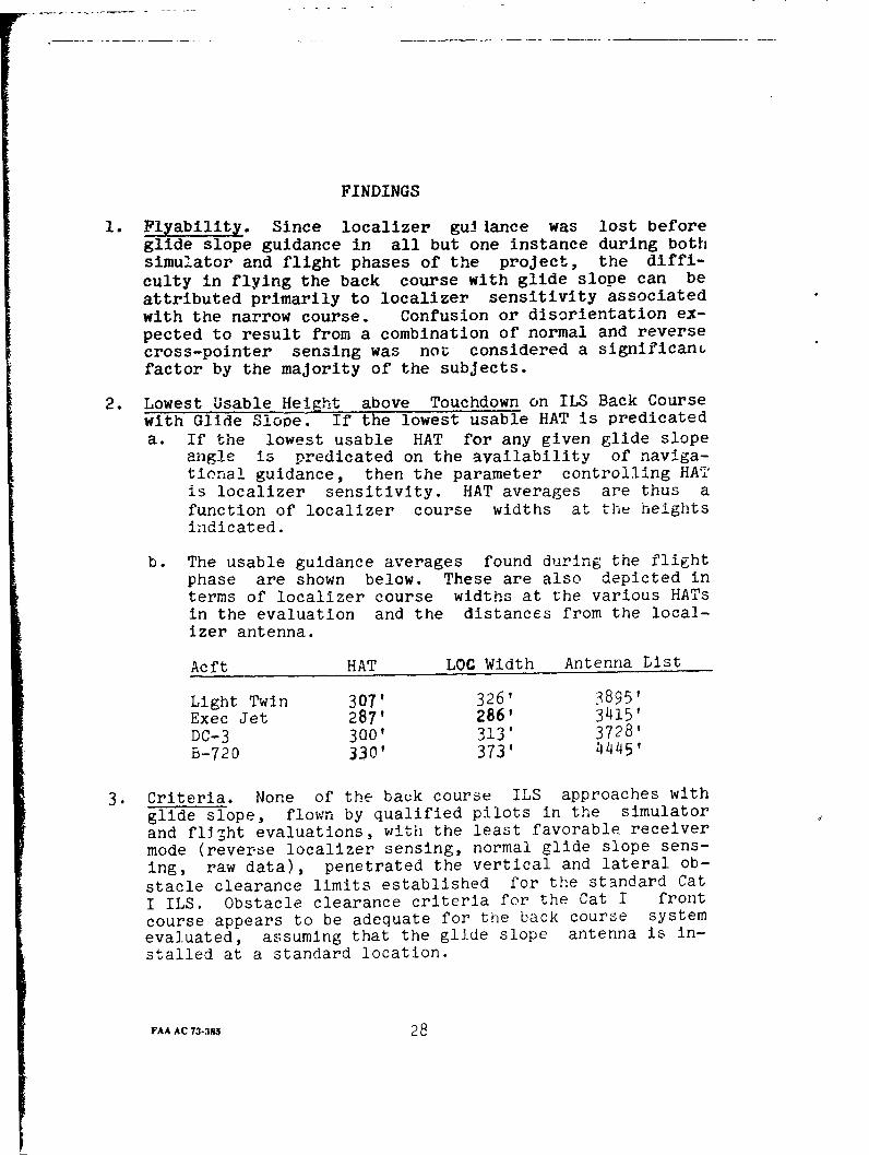
1. Flyability. Since localizer gui lance was lost beforeglide slope guidance in all but one instance during bothsimulator and flight phases of the project, the diffi-
culty in flying the back course with glide slope can be
attributed primarily to localizer sensitivity associatedwith the narrow course. Confusion or disorientation ex-pected to result from a combination of normal and reversecross-pointer sensing was not considered a significanGfactor by the majority of the subjects.
2. Lowest Usable Height above Touchdown on ILS Back Coursewith Glide Slooe. If the lowest usable HAT is predicateda. If the lowest usable HAT for any given glide slope
angle is predicated on the availability of naviga-tional guidance, then the parameter controlling HAT
is localizer sensitivity. HAT averages are thus afunction of localizer course widths at the heightsindicated.
b. The usable guidance averages found during the flightphase are shown below. These are also depicted interms of localizer course widths at the various HATsin the evaluation and the distances from the local-izer antenna.
Acft HAT LOC Width Antenna Dist
Light Twin 307' 326' 3895'Exec Jet 287' 286' 3415'
DC-3 300' 313' 3728'B-720 330' 373' 44451
3. Criteria. None of the back course ILS approaches with
glide slope, flown by qualified pilots in the simulator
and fli-ht evaluations, with the least favorable receivermode (reverse localizer sensing, normal glide slope sens-ing, raw data), penetrated the vertical and lateral ob-
stacle clearance limits established for the standard Cat
I ILS. Obstacle clearance criteria for the Cat I front
course appears to be adequate for the back course systemevaluated, assuming that the glide slope antenna is in-stalled at a standard location.
FAA AC 73-385 28
Related Documents