Standard Form 298 (Rev 8/98) Prescribed by ANSI Std. Z39.18 W911NF-13-1-0098 713-348-5304 Ph.D. Dissertation 63302-CS-ACI.2 a. REPORT 14. ABSTRACT 16. SECURITY CLASSIFICATION OF: Future extreme-scale systems are expected to contain homogeneous and heterogeneous many-core processors, with O(103) cores per node and O(106) nodes overall. Effective combination of inter-node and intra-node parallelism is recognized to be a major software challenge for such systems. Further, applications will have to deal with constrained energy budgets as well as frequent faults and failures. To aid programmers manage these complexities and enhance programmability, much of recent research has focussed on designing state-of-art software runtime systems. Such runtime systems are expected to be a critical component of the software ecosystem for the 1. REPORT DATE (DD-MM-YYYY) 4. TITLE AND SUBTITLE 13. SUPPLEMENTARY NOTES 12. DISTRIBUTION AVAILIBILITY STATEMENT 6. AUTHORS 7. PERFORMING ORGANIZATION NAMES AND ADDRESSES 15. SUBJECT TERMS b. ABSTRACT 2. REPORT TYPE 17. LIMITATION OF ABSTRACT 15. NUMBER OF PAGES 5d. PROJECT NUMBER 5e. TASK NUMBER 5f. WORK UNIT NUMBER 5c. PROGRAM ELEMENT NUMBER 5b. GRANT NUMBER 5a. CONTRACT NUMBER Form Approved OMB NO. 0704-0188 3. DATES COVERED (From - To) - UU UU UU UU 02-10-2014 Approved for public release; distribution is unlimited. Runtime Systems for Extreme Scale Platforms The views, opinions and/or findings contained in this report are those of the author(s) and should not contrued as an official Department of the Army position, policy or decision, unless so designated by other documentation. 9. SPONSORING/MONITORING AGENCY NAME(S) AND ADDRESS (ES) U.S. Army Research Office P.O. Box 12211 Research Triangle Park, NC 27709-2211 dynamic task parallelism, locality control REPORT DOCUMENTATION PAGE 11. SPONSOR/MONITOR'S REPORT NUMBER(S) 10. SPONSOR/MONITOR'S ACRONYM(S) ARO 8. PERFORMING ORGANIZATION REPORT NUMBER 19a. NAME OF RESPONSIBLE PERSON 19b. TELEPHONE NUMBER Vivek Sarkar Sanjay Chatterjee c. THIS PAGE The public reporting burden for this collection of information is estimated to average 1 hour per response, including the time for reviewing instructions, searching existing data sources, gathering and maintaining the data needed, and completing and reviewing the collection of information. Send comments regarding this burden estimate or any other aspect of this collection of information, including suggesstions for reducing this burden, to Washington Headquarters Services, Directorate for Information Operations and Reports, 1215 Jefferson Davis Highway, Suite 1204, Arlington VA, 22202-4302. Respondents should be aware that notwithstanding any other provision of law, no person shall be subject to any oenalty for failing to comply with a collection of information if it does not display a currently valid OMB control number. PLEASE DO NOT RETURN YOUR FORM TO THE ABOVE ADDRESS. William Marsh Rice University 6100 Main St., MS-16 Houston, TX 77005 -1827

Welcome message from author
This document is posted to help you gain knowledge. Please leave a comment to let me know what you think about it! Share it to your friends and learn new things together.
Transcript
Standard Form 298 (Rev 8/98) Prescribed by ANSI Std. Z39.18
W911NF-13-1-0098
713-348-5304
Ph.D. Dissertation
63302-CS-ACI.2
a. REPORT
14. ABSTRACT
16. SECURITY CLASSIFICATION OF:
Future extreme-scale systems are expected to contain homogeneous and heterogeneous many-core processors, with O(103) cores per node and O(106) nodes overall. Effective combination of inter-node and intra-node parallelism is recognized to be a major software challenge for such systems. Further, applications will have to deal with constrained energy budgets as well as frequent faults and failures. To aid programmers manage these complexities and enhance programmability, much of recent research has focussed on designing state-of-art software runtime systems. Such runtime systems are expected to be a critical component of the software ecosystem for the
1. REPORT DATE (DD-MM-YYYY)
4. TITLE AND SUBTITLE
13. SUPPLEMENTARY NOTES
12. DISTRIBUTION AVAILIBILITY STATEMENT
6. AUTHORS
7. PERFORMING ORGANIZATION NAMES AND ADDRESSES
15. SUBJECT TERMS
b. ABSTRACT
2. REPORT TYPE
17. LIMITATION OF ABSTRACT
15. NUMBER OF PAGES
5d. PROJECT NUMBER
5e. TASK NUMBER
5f. WORK UNIT NUMBER
5c. PROGRAM ELEMENT NUMBER
5b. GRANT NUMBER
5a. CONTRACT NUMBER
Form Approved OMB NO. 0704-0188
3. DATES COVERED (From - To)-
UU UU UU UU
02-10-2014
Approved for public release; distribution is unlimited.
Runtime Systems for Extreme Scale Platforms
The views, opinions and/or findings contained in this report are those of the author(s) and should not contrued as an official Department of the Army position, policy or decision, unless so designated by other documentation.
9. SPONSORING/MONITORING AGENCY NAME(S) AND ADDRESS(ES)
U.S. Army Research Office P.O. Box 12211 Research Triangle Park, NC 27709-2211
dynamic task parallelism, locality control
REPORT DOCUMENTATION PAGE
11. SPONSOR/MONITOR'S REPORT NUMBER(S)
10. SPONSOR/MONITOR'S ACRONYM(S) ARO
8. PERFORMING ORGANIZATION REPORT NUMBER
19a. NAME OF RESPONSIBLE PERSON
19b. TELEPHONE NUMBERVivek Sarkar
Sanjay Chatterjee
c. THIS PAGE
The public reporting burden for this collection of information is estimated to average 1 hour per response, including the time for reviewing instructions, searching existing data sources, gathering and maintaining the data needed, and completing and reviewing the collection of information. Send comments regarding this burden estimate or any other aspect of this collection of information, including suggesstions for reducing this burden, to Washington Headquarters Services, Directorate for Information Operations and Reports, 1215 Jefferson Davis Highway, Suite 1204, Arlington VA, 22202-4302. Respondents should be aware that notwithstanding any other provision of law, no person shall be subject to any oenalty for failing to comply with a collection of information if it does not display a currently valid OMB control number.PLEASE DO NOT RETURN YOUR FORM TO THE ABOVE ADDRESS.
William Marsh Rice University6100 Main St., MS-16
Houston, TX 77005 -1827

ABSTRACT
Runtime Systems for Extreme Scale Platforms
Report Title
Future extreme-scale systems are expected to contain homogeneous and heterogeneous many-core processors, with O(103) cores per node and O(106) nodes overall. Effective combination of inter-node and intra-node parallelism is recognized to be a major software challenge for such systems. Further, applications will have to deal with constrained energy budgets as well as frequent faults and failures. To aid programmers manage these complexities and enhance programmability, much of recent research has focussed on designing state-of-art software runtime systems. Such runtime systems are expected to be a critical component of the software ecosystem for the management of parallelism, locality, load balancing, energy and resilience on extreme-scale systems.In this dissertation, we address three key challenges faced by a runtime system using a dynamic task parallel framework for extreme-scale computing. First, we address the challenge of integrating an intra-node task parallel runtime with a communication system for scalable performance. We present a runtime communication system, called HC-COMM, designed to use dedicated communication cores on a system. We introduce the HCMPI programming model which integrates the Habanero-C asynchronous dynamic task parallel language with the MPI message passing communication model on the HC-COMM runtime. We also introduce the HAPGNS model that enables data flow programming for extreme-scale systems in which the user does not require knowledge of MPI. Second, we address the challenge of separating locality optimizations from a programmer with domain specific knowledge. We present a tuning framework, through which performance experts can optimize existing applications by specifying runtime operations aimed at co-scheduling of affinitized tasks. Finally, we address the challenge of scalable synchronization for long running tasks on a dynamic task parallel runtime. We use the phaser construct to present a generalized tree-based synchronization algorithm and support unified collective operations at both inter-node and intra-node levels. Overcoming these runtime challenges are a first step towards effective programming on extreme-scale systems.

RICE UNIVERSITY
Runtime Systems for Extreme Scale Platforms
by
Sanjay Chatterjee
A Thesis Submittedin Partial Fulfillment of theRequirements for the Degree
Doctor of Philosophy
Approved, Thesis Committee:
Vivek Sarkar, ChairE.D. Butcher Chair in EngineeringProfessor of Computer Science
John Mellor-CrummeyProfessor of Computer Science
Lin ZhongAssociate Professor of Electrical andComputer Engineering
Zoran BudimlicResearch Scientist
Houston, Texas
December, 2013

ABSTRACT
Runtime Systems for Extreme Scale Platforms
by
Sanjay Chatterjee
Future extreme-scale systems are expected to contain homogeneous and hetero-
geneous many-core processors, with O(103) cores per node and O(106) nodes overall.
Effective combination of inter-node and intra-node parallelism is recognized to be a
major software challenge for such systems. Further, applications will have to deal
with constrained energy budgets as well as frequent faults and failures. To aid pro-
grammers manage these complexities and enhance programmability, much of recent
research has focussed on designing state-of-art software runtime systems. Such run-
time systems are expected to be a critical component of the software ecosystem for
the management of parallelism, locality, load balancing, energy and resilience on
extreme-scale systems.
In this dissertation, we address three key challenges faced by a runtime system us-
ing a dynamic task parallel framework for extreme-scale computing. First, we address
the challenge of integrating an intra-node task parallel runtime with a communication
system for scalable performance. We present a runtime communication system, called
HC-COMM, designed to use dedicated communication cores on a system. We intro-
duce the HCMPI programming model which integrates the Habanero-C asynchronous
dynamic task parallel language with the MPI message passing communication model
on the HC-COMM runtime. We also introduce the HAPGNS model that enables data

flow programming for extreme-scale systems in which the user does not require knowl-
edge of MPI. Second, we address the challenge of separating locality optimizations
from a programmer with domain specific knowledge. We present a tuning framework,
through which performance experts can optimize existing applications by specifying
runtime operations aimed at co-scheduling of affinitized tasks. Finally, we address
the challenge of scalable synchronization for long running tasks on a dynamic task
parallel runtime. We use the phaser construct to present a generalized tree-based syn-
chronization algorithm and support unified collective operations at both inter-node
and intra-node levels. Overcoming these runtime challenges are a first step towards
effective programming on extreme-scale systems.

Acknowledgments
It was an honor and a gift to have had Prof. Vivek Sarkar as my PhD advisor.
Working with him has been a truly great learning experience for me. He is one of
most brilliant and knowledgable researchers I have known, and yet he is a lesson in
humility and generosity. He participated in my research with great enthusiasm and
his guidance was critical for constructing my dissertation. His faith and confidence in
my work encouraged me to pursue exploratory research on diverse topics. He always
made himself available for discussions and even patiently sat through many Sunday
afternoons providing critical assessment of my blue-sky ideas. I am really thankful for
his support throughout my PhD years, through thick and thin, both academic and
personal, and when everything just seemed piled higher and deeper. He inspires me
to be a better human being, and that, in my eyes, makes him the complete advisor.
I would like to express my gratitude to Prof. John Mellor-Crummey for agreeing
to be on my thesis committee and supporting my research work by providing access
to the Jaguar supercomputer at Oak Ridge National Labs. The experimental results
on Jaguar are the cornerstone of my thesis and this dissertation would have been
incomplete without his help. I am really thankful for his detailed feedback on my
dissertation drafts which helped improve my writeup manyfold. I have also greatly
enjoyed being part of two parallel computing courses taught by John. I gained deep
insight into the nuances of dealing with concurrency issues and they helped me greatly
in constructing the runtime algorithms and data structures in this dissertation.
I would like to sincerely thank Prof. Lin Zhong for agreeing to be on my thesis
committee. His insights and feedback were very important in shaping my thesis and
helped me to keep the broader picture in mind for my dissertation.
I am grateful to Zoran Budimlic for agreeing be on my thesis committee. I worked
with Zoran almost on a day-to-day basis during my PhD. He is always up for quick
chats, hallway discussions and deep dive meetings. I have greatly enjoyed interacting
with him and am really thankful for his technical contributions to my research work.

I would like to thank Kath Knobe of Intel for inspiring my work on the tuning
framework. I remember meeting Kath at Intel during my internship at Hillsboro
where she was presenting her ideas on tuning. I spoke to her about similar ideas and
we started collaborating after I returned to Rice.
I would like to thank all Habanero group members, both past and present, for
helping me with discussions, feedback and insights related my work. Specifically, I
would like to thank Max Grossman for our collaboration on numerous topics, and
Vincent Cave for many technical discussions, code reviews and helping with experi-
mental results on many projects. I would also like to thank Jun Shirako for helping
me with the phaser discussions, and Yonghong Yan for setting up much of the runtime
infrastructure. I am thankful to Sagnak Tasırlar and Milind Chabbi for painstakingly
collecting results which have greatly helped this dissertation. I will always be grateful
to Raghavan Raman for introducing me to my advisor and helping me with my ap-
plication process. I would like to thank all the wonderful office administration staff in
the Computer Science department for making sure my life went smoothly, and Ratna
Sarkar for graciously hosting the Habanero group members on many occasions.
I would like to thank my friends who have helped me remain sane during my
PhD. I want to particularly thank my friend Pratim Chowdhury for being an immense
support during the last few months before graduation.
Finally, I am ever thankful to my wonderful and supportive family. I cannot
imagine my PhD years without their help. My parents have always motivated me
with their great enthusiasm and respect for higher education. To this day, their
belief in me inspires me to overcome the greatest of challenges in my life. My wife,
Sucharita, has been my best friend and greatest source of strength during my PhD
years with her unfathomable love and immense sacrifice. The happiest moment of my
life arrived when our daughter, Anousha, was born. I feel so proud to have shared
my PhD journey with my family and so I end with the following dedication.

To my mother, Ranu
To my father, Sanjiban
To my sister, Srimoyee
To my daughter, Anousha
To my beloved wife and my greatest strength, Sucharita

Contents
Abstract ii
List of Illustrations x
List of Tables xiii
1 Introduction 1
1.1 Thesis Statement . . . . . . . . . . . . . . . . . . . . . . . . . . . . . 7
1.2 Organization of this Dissertation . . . . . . . . . . . . . . . . . . . . 8
2 Related Work 10
3 Background 23
3.1 Dynamic Task Parallelism . . . . . . . . . . . . . . . . . . . . . . . . 23
3.2 Habanero-C: Intra-node Task Parallelism . . . . . . . . . . . . . . . . 27
3.2.1 HC Task Model . . . . . . . . . . . . . . . . . . . . . . . . . . 27
3.2.2 HC Data Driven Task Model . . . . . . . . . . . . . . . . . . . 30
3.2.3 HC Runtime . . . . . . . . . . . . . . . . . . . . . . . . . . . . 31
4 Habanero-C Runtime Communication System 35
4.1 HCMPI Programming Model . . . . . . . . . . . . . . . . . . . . . . 38
4.1.1 HCMPI Structured Communication Task Model . . . . . . . . 41
4.1.2 HCMPI Message Driven Task Model . . . . . . . . . . . . . . 42
4.1.3 HCMPI Implementation for MPI Blocking Semantics . . . . . 43
4.1.4 HCMPI Collective Synchronization Model . . . . . . . . . . . 45
4.2 HC-COMM Runtime Implementation . . . . . . . . . . . . . . . . . . 46

viii
4.3 Results . . . . . . . . . . . . . . . . . . . . . . . . . . . . . . . . . . . 51
4.3.1 Micro-benchmark Experiments . . . . . . . . . . . . . . . . . . 51
4.3.2 UTS Case Study: . . . . . . . . . . . . . . . . . . . . . . . . . 55
4.4 Summary . . . . . . . . . . . . . . . . . . . . . . . . . . . . . . . . . 68
5 Locality Control of Compute and Data 69
5.1 Research Contributions . . . . . . . . . . . . . . . . . . . . . . . . . . 70
5.2 The Habanero Asynchronous Partitioned Global Name Space Model . 71
5.2.1 HAPGNS Programming Model . . . . . . . . . . . . . . . . . 72
5.2.2 Implementation . . . . . . . . . . . . . . . . . . . . . . . . . . 75
5.2.3 Results . . . . . . . . . . . . . . . . . . . . . . . . . . . . . . . 77
5.3 Habanero-C Tuning Framework . . . . . . . . . . . . . . . . . . . . . 79
5.3.1 Hierarchical Place Trees for Spatial Locality . . . . . . . . . . 80
5.3.2 Tuning Framework for Spatio-Temporal Task Locality . . . . . 83
5.3.3 HPT Implementation . . . . . . . . . . . . . . . . . . . . . . . 86
5.3.4 Tuning Tree Implementation . . . . . . . . . . . . . . . . . . . 93
5.3.5 Results . . . . . . . . . . . . . . . . . . . . . . . . . . . . . . . 95
5.4 Summary . . . . . . . . . . . . . . . . . . . . . . . . . . . . . . . . . 107
6 Task Synchronization for Iterative Computation 108
6.1 Past Work on Phaser Synchronization Model . . . . . . . . . . . . . . 110
6.1.1 Phaser Programming Model in HJ . . . . . . . . . . . . . . . . 111
6.1.2 Hierarchical Phasers for Tree-based Barriers in HJ . . . . . . . 116
6.1.3 Phaser Implementation in HJ . . . . . . . . . . . . . . . . . . 119
6.2 Research Contributions . . . . . . . . . . . . . . . . . . . . . . . . . . 121
6.3 Phasers for Multicore Synchronization . . . . . . . . . . . . . . . . . 122
6.3.1 Programming Model for Habanero-C . . . . . . . . . . . . . . 122
6.3.2 Phaser Data Structure . . . . . . . . . . . . . . . . . . . . . . 124
6.3.3 A Generalized Tree-based Phaser Synchronization Algorithm . 128

ix
6.3.4 Results . . . . . . . . . . . . . . . . . . . . . . . . . . . . . . . 140
6.4 Phasers for Manycore Synchronization . . . . . . . . . . . . . . . . . 144
6.4.1 Optimization Using Hardware Barriers . . . . . . . . . . . . . 145
6.4.2 Optimization Using Thread Suspend and Awake . . . . . . . . 146
6.4.3 Adaptive Phasers . . . . . . . . . . . . . . . . . . . . . . . . . 147
6.4.4 Memory Optimizations . . . . . . . . . . . . . . . . . . . . . . 148
6.4.5 Results . . . . . . . . . . . . . . . . . . . . . . . . . . . . . . . 148
6.5 Phasers for Hybrid Synchronization . . . . . . . . . . . . . . . . . . . 151
6.5.1 Implementation . . . . . . . . . . . . . . . . . . . . . . . . . . 153
6.5.2 Results . . . . . . . . . . . . . . . . . . . . . . . . . . . . . . . 155
6.6 Summary . . . . . . . . . . . . . . . . . . . . . . . . . . . . . . . . . 157
7 Conclusions 159
Bibliography 163

Illustrations
3.1 An example code schema with async and finish constructs . . . . . . . 28
3.2 Task parallel programming using async and finish1 . . . . . . . . . . . 29
3.3 Deque operations for a workstealing runtime . . . . . . . . . . . . . . 33
4.1 HCMPI Structured Communication Tasks: Starting asynchronous
communication and waiting for for its completion. . . . . . . . . . . . 42
4.2 HCMPI Await Model . . . . . . . . . . . . . . . . . . . . . . . . . . . 43
4.3 Using the finish construct in HCMPI. A finish around HCMPI Irecv, a
non-blocking call, implements HCMPI Recv, a blocking call. . . . . . . 44
4.4 HCMPI Wait and Status Model . . . . . . . . . . . . . . . . . . . . . 45
4.5 HCMPI Barrier Model . . . . . . . . . . . . . . . . . . . . . . . . . . 46
4.6 The HC-COMM Intra-node Runtime System . . . . . . . . . . . . . . 47
4.7 Lifecycle of a Communication Task . . . . . . . . . . . . . . . . . . . 48
4.8 HC-COMM DDF Runtime . . . . . . . . . . . . . . . . . . . . . . . . 49
4.9 Thread Micro-benchmarks for MVAPICH2 on Rice DAVinCI cluster
with Infiniband interconnect . . . . . . . . . . . . . . . . . . . . . . . 53
4.10 Thread Micro-benchmarks for MPICH2 on Jaguar Cray XK6 with
Gemini interconnect . . . . . . . . . . . . . . . . . . . . . . . . . . . 54
4.11 Scaling of UTS on MPI. . . . . . . . . . . . . . . . . . . . . . . . . . 59
4.12 Scaling of UTS on HCMPI. . . . . . . . . . . . . . . . . . . . . . . . 60
4.13 HCMPI speedup compared to MPI . . . . . . . . . . . . . . . . . . . 61

xi
4.14 HCMPI speedup compared to MPI on UTS T3XXL with extra
communication worker . . . . . . . . . . . . . . . . . . . . . . . . . . 62
4.15 HCMPI Speedup compared to MPI+OpenMP on UTS T1XXL . . . . 66
5.1 Simplified Smith-Waterman implementation . . . . . . . . . . . . . . 74
5.2 Smith-Waterman dependency graph, its hierarchical tiling and
execution wavefronts . . . . . . . . . . . . . . . . . . . . . . . . . . . 75
5.3 Scaling results for Smith-Waterman for 8 to 96 nodes with 2 to 12 cores 78
5.4 An example HPT structure . . . . . . . . . . . . . . . . . . . . . . . 82
5.5 Tuning tree of queues matches the target platform structure . . . . . 84
5.6 Tuning action to unpack a group and move down the steps . . . . . . 86
5.7 An example of a HPT XML description . . . . . . . . . . . . . . . . . 87
5.8 Bucket deque expansion . . . . . . . . . . . . . . . . . . . . . . . . . 90
5.9 Bucket deque reuse after contraction . . . . . . . . . . . . . . . . . . 91
5.10 Releasing steps from tuning tree to domain tree . . . . . . . . . . . . 93
5.11 Cholesky decomposition dependences . . . . . . . . . . . . . . . . . . 96
5.12 Cholesky decomposition execution times for various tile sizes . . . . . 97
5.13 Tuning actions on GroupC, the outer level group in Cholesky . . . . . 100
5.14 Set1 Cholesky Tuning experiments on 2000 x 2000 matrix . . . . . . . 101
5.15 Set2 Cholesky Tuning experiments on 6000 x 6000 matrix . . . . . . . 101
5.16 Rician denoising dependencies . . . . . . . . . . . . . . . . . . . . . . 103
5.17 Grouped rician denoising steps . . . . . . . . . . . . . . . . . . . . . . 103
5.18 Pyramid computation for tiles in successive iterations . . . . . . . . . 104
5.19 Rician Denoising performance comparison of untuned vs tuned . . . . 104
6.1 Phaser Mode Lattice . . . . . . . . . . . . . . . . . . . . . . . . . . . 111
6.2 Semantics of synchronization operation . . . . . . . . . . . . . . . . . 111
6.3 Single-level phaser with single master . . . . . . . . . . . . . . . . . . 117

xii
6.4 Hierarchical phaser with sub-masters . . . . . . . . . . . . . . . . . . 118
6.5 Data structures for flat phaser . . . . . . . . . . . . . . . . . . . . . . 119
6.6 Data structures for tree phaser . . . . . . . . . . . . . . . . . . . . . . 120
6.7 Barrier Example . . . . . . . . . . . . . . . . . . . . . . . . . . . . . 124
6.8 Generalized Phaser Tree Data Structure (Degree = 2) . . . . . . . . . 125
6.9 Barrier Synchronization on x86 node . . . . . . . . . . . . . . . . . . 141
6.10 Barrier Synchronization on Power7 node . . . . . . . . . . . . . . . . 142
6.11 Phaser barrier overhead on a dual-CPU Niagara T2 machine . . . . . 143
6.12 Cyclops64 Architecture Details . . . . . . . . . . . . . . . . . . . . . 144
6.13 SRAM optimization for phasers on Cyclops64 . . . . . . . . . . . . . 149
6.14 Barrier and Point-to-Point Microbenchmarks . . . . . . . . . . . . . . 150
6.15 HCMPI Phaser Barrier Model . . . . . . . . . . . . . . . . . . . . . . 152
6.16 HCMPI Phaser Accumulator Model . . . . . . . . . . . . . . . . . . . 154
6.17 HCMPI Phaser Barrier . . . . . . . . . . . . . . . . . . . . . . . . . . 155

Tables
1.1 The exascale challenge . . . . . . . . . . . . . . . . . . . . . . . . . . 2
4.1 HCMPI Types . . . . . . . . . . . . . . . . . . . . . . . . . . . . . . . 39
4.2 HCMPI API for point-to-point and collective communication . . . . . 40
4.3 HCMPI Runtime API . . . . . . . . . . . . . . . . . . . . . . . . . . 41
4.4 Best UTS configurations on Jaguar for 64 compute nodes . . . . . . . 57
4.5 UTS overhead analysis for T1XXL runs on Jaguar . . . . . . . . . . . 63
6.1 Semantics of phaser operations as a function of registration mode on ph114
6.2 Cyclops64 TNT APIs for Hardware Synchronization Primitives . . . . 145
6.3 HCMPI PHASER API . . . . . . . . . . . . . . . . . . . . . . . . . . 151
6.4 HCMPI Ops . . . . . . . . . . . . . . . . . . . . . . . . . . . . . . . . 153
6.5 EPCC Syncbench with MVAPICH2 on Infiniband . . . . . . . . . . . 157

xiv
List of Algorithms
1 Push operation for resizable deques . . . . . . . . . . . . . . . . . . . . 92
2 PhaserRegistration . . . . . . . . . . . . . . . . . . . . . . . . . . . . . 129
3 InsertSigIntoPhaserTree . . . . . . . . . . . . . . . . . . . . . . . . . . 131
4 FixSubPhaser . . . . . . . . . . . . . . . . . . . . . . . . . . . . . . . . 132
5 PhaserSignal . . . . . . . . . . . . . . . . . . . . . . . . . . . . . . . . 134
6 PhaserWait . . . . . . . . . . . . . . . . . . . . . . . . . . . . . . . . . 135
7 doWaitTree . . . . . . . . . . . . . . . . . . . . . . . . . . . . . . . . . 136
8 doWaitNode . . . . . . . . . . . . . . . . . . . . . . . . . . . . . . . . 136
9 doWaitPhaser . . . . . . . . . . . . . . . . . . . . . . . . . . . . . . . . 137
10 PhaserDropSig . . . . . . . . . . . . . . . . . . . . . . . . . . . . . . . 139

1
Chapter 1
Introduction
As we head towards exascale computing, future software technology needs to embrace
systems using homogeneous and heterogeneous many-core processors [1]. Based on
the design targets from the exascale challenge program by DARPA [2] shown in Ta-
ble 1.1, future extreme-scale systems are projected to use up to O(103) processor cores
per compute node and O(106) nodes overall. The primary software challenges on such
systems are to efficiently express and manage large scales of parallelism of variable
granularity (to address platform heterogeneity) on constrained energy budgets and
being resilient to faults and failures. The performance of these systems will heavily
depend on the entire software stack, spanning programming models, languages, com-
pilers, runtime systems and operating systems. It is critical to find software solutions
that can effectively exploit the extreme-scale of combined inter-node and intra-node
parallelism. Current state-of-the-art techniques that combine distributed- and shared-
memory programming models, have demonstrated the potential benefits of combining
both levels of parallelism, including increased communication-computation overlap,
improved memory utilization, and effective use of accelerators. However, these hybrid
programming approaches often require significant rewrites of application code and
assume a high level of programmer expertise.
One popular direction is to integrate asynchronous task parallelism with a Parti-
tioned Global Address Space (PGAS) [3] model as exemplified by the DARPA HPCS
programming languages (Chapel [4] and X10 [5]), and by recent multithreading ex-

2
Systems 2015 2018
System Peak Flops 100-200 Peta 1 Exa
System Memory 5 PB 10 PB
Node Performance 400 GF 1-10 TF
Node Memory Bandwidth 100 GB/s 200-400 GB/s
Interconnect Bandwidth 25 GB/s 50 GB/s
Node Concurrency O(100) O(1000)
System Size (Nodes) 500000 O(Million)
Total Concurrency 50 Million O(Billion)
Storage 150 PB 300 PB
I / O 10 TB/s 20 TB/s
Power 10 MW 20 MW
Table 1.1 : The exascale challenge
tensions to established PGAS languages (UPC [6] and CAF [7]). PGAS programming
models offer HPC programmers a single-level partition of a global address space with
control of data-to-thread affinity/locality. In contrast, the Message Passing Interface
(MPI) [8] still provides an effective path for implementing the majority of applications
on the largest supercomputers in the world. Although it has been shown that there
are certain classes of applications for which the PGAS models are superior, many
challenges still remain for the PGAS languages to catch up with MPI in supporting
these applications due to the overheads associated with maintaining a global address
space, as well as the software engineering challenges of migrating MPI-based codes
to PGAS. On the other hand, harnessing O(103)-way parallelism at the intra-node

3
level will be a major challenge for both MPI and PGAS programmers, for multiple
reasons. The parallelism will have to exploit strong rather than weak scaling, since
the memory per node is not increasing at the same rate as the number of cores per
node. Finally, programs will have to be amenable to dynamic adaptive scheduling
techniques to deal with heterogeneous processors, non-uniform clock speeds and other
load imbalances across cores due to power management, fault tolerance, and other
runtime services.
Dynamic task parallelism is one model that is well suited to addressing these im-
balances at the intra-node level. It is now recognized as a programming model that
combines the best of performance and programmability for shared-memory computa-
tions. Dynamic task parallel languages, such as Habanero-C [9], Cilk [10] and X10 [5],
can express fine-grained parallelism with the help of lightweight tasks and are assisted
by efficient load balancing runtime systems for achieving scalable performance. The
runtimes typically depend on hardware support for fast atomic operations to im-
plement high frequency task load-balancing operations on shared-memory multicore
systems. While recent MPI [8] standards have made provisions for remote atomic
communication calls, such as MPI COMPARE AND SWAP, it is infeasible to replicate the
current shared-memory runtime model at the inter-node level because the latency of
load balancing operations will be prohibitively high at the inter-node level. Further,
whereas in a shared-memory multithreaded work-stealing runtime, a thief does not
interrupt the work of the victim during a steal operation, distributed work-stealing
usually requires victim participation. Future runtimes will need specific hardware
and software support to address these problems.
In our work, we focus on the critical role played by the runtime system in en-
abling programmability in upper layers of the software stack that interface with the

4
programmer, and in enabling performance in lower levels of the software stack that
interface with the hardware. The scope of our research can be broadly classified
into three specific areas where the runtime system will have a major impact on the
performance.
• Designing scalable runtime communication systems
• Enabling locality control of compute and data at runtime
• Efficient synchronization for iterative computations in long running tasks
This work builds on the Habanero-C (HC) language [9, 11] which provides dy-
namic asynchronous task parallelism support with the async and finish constructs
on a shared-memory platform. We have implemented the phaser task synchroniza-
tion construct and the Hierarchical Place Tree (HPT) model in HC, based on past
work [12, 13]. A phaser is a unification of point-to-point and collective task synchro-
nization. It is an efficient synchronization model for applications with long running
synchronized tasks. A HPT is a user defined runtime data structure that allows tasks
to be scheduled with affinity towards a core or set of cores. The affinity is modeled
as a tree of places which typically represent the memory hierarchy of the system and
the runtime executes tasks which are closer in the hierarchy first before going further
out. This allows the user to execute parallel tasks which share data access to benefit
from spatial locality at some level of the memory hierarchy.
We have integrated the intra-node HC model with a communication layer (cur-
rently MPI), to create a runtime execution model for distributed systems, called
HC-COMM. Our goal is to ensure scalable performance on extreme-scale systems
along with easy portability of existing applications and enhanced programmability
for future applications. The HCMPI (Habanero-C MPI) programming model, offers

5
a practical approach for programmers wanting to take incremental transitional steps
starting from either a shared- or distributed-memory program. It is a unified pro-
gramming model for shared and distributed memory systems with integrated support
for asynchronous intra-node tasking and asynchronous inter-node communication us-
ing the MPI message passing interface. All MPI calls are treated as asynchronous
tasks, thereby enabling unified handling of messages and tasking constructs. Point-to-
point communication tasks can be offloaded from the computation task’s critical path.
System-wide collective synchronization is achieved with integrated task- and process-
level collective synchronization using phaser primitives. We achieve our portability
goals by providing easy transitional steps for introducing shared-memory task paral-
lelism to sequential MPI programs, or for introducing MPI calls to shared-memory
task parallel programs.
We also introduce HAPGNS (Habanero Asynchronous Partitioned Global Name
Space) as a distributed data-driven programming model that integrates intra-node
and inter-node data-flow programming. This model does not require any knowledge
of MPI. In this model, producer and consumer tasks, called data-driven tasks, com-
municate data using put and get operations. Consumer tasks specify the set of data
dependences using distributed data driven future (DDDF) objects. A DDDF object
carries a globally unique identifier which helps tasks to communicate data in a global
name space.
The HC-COMM runtime design uses dedicated communication cores on the sys-
tem. Our approach is motivated in part by the fact that future extreme scale systems,
driven by a limited power budget, will have reduced shared-memory capacities, lead-
ing to an increased focus on efficient communication. For applications, this translates
to exploiting overlaps between computation and communication for improved per-

6
formance. Our design is based on the premise that it will be feasible to dedicate
one or more cores per node to serve as communication workers in future many-core
architectures. Thus, a program’s workload can be divided into computation and com-
munication tasks that run on computation and communication workers respectively.
Our experimental results show that even for today’s multicore architectures, the ben-
efits of a dedicated communication worker can outweigh the loss of a computation
resource. Further, the foundational synchronization constructs in our programming
model such as finish, phaser and await can be applied uniformly to computation tasks
and communication tasks.
We propose data locality optimization techniques at both inter-node and intra-
node level. Locality aware distribution functions in the HAPGNS model control inter-
node data locality. Within a node, programs can benefit from spatial and temporal
data reuse at cache hierarchies with the help of the HPT runtime data structure.
We have designed a tuning framework which can enable performance experts, to
contribute performance improvements via tuning operations on existing applications.
Tuning experts with detailed knowledge of a machine’s characteristics can guide or
tune an application’s schedule at runtime using a set of API functions. The tuning
framework layer, which is an abstraction on top of the task execution runtime, is
able to dynamically decide where to execute a task. This decision power enables the
tuning expert to co-locate tasks that will benefit from spatial and/or temporal data
reuse.
An HCMPI program follows a task parallel model within a node and a SPMD
model across nodes. It supports many commonly-used synchronous, asynchronous
and collective MPI operations. We present a synchronization scheme for combined
inter-node and intra-node collective operations using the phaser model.

7
1.1 Thesis Statement
Programming extreme-scale platforms can be aided by a unified runtime system that
combines inter-node communication with intra-node computation, extends work-stealing
schedulers with hierarchies and affinities for locality, and supports scalable synchro-
nization primitives for long running iterative tasks.
Runtime systems are expected to have a major impact on the performance of
extreme-scale systems. They play a critical role in enabling high performance, pro-
grammability, and productivity for dynamic task parallel systems on shared-memory
platforms. Runtime systems that support dynamic task parallelism have demon-
strated scalable performance for shared-memory programs. However, using such run-
times for extreme-scale computing throw up few key challenges.
First, a scalable runtime communication system will be a key enabler for extreme-
scale computing. The runtime should leverage benefits of asynchronous dynamic task
parallel programming models, as well as the scalability of popular communication
models. It has to overlap communication with computation as well as manage con-
tention on the communication sub-system.
Second, locality of computation and data is critical for performance and lower
energy resulting from data reuse on faster memories and redundant communication
avoidance. The runtime has to leverage both spatial and temporal locality of com-
pute and data. A programmer should be able to express affinities between task
computations and associated data to help the runtime make locality guided schedul-
ing decisions. Abstracting the hardware characteristics with an appropriate machine
model will also help the runtime in making intelligent scheduling decisions.
Third, efficient synchronization models for iterative computations in long running

8
tasks will be an important scalability requirement for task parallelism. The model
should support the expression of various synchronization patterns. The runtime sys-
tem should enable collective synchronization across compute nodes with unified prim-
itives at intra-node and inter-node levels, as well as leverage hardware support when
available.
Runtime support for scalable locality aware task scheduling and synchronization
at both intra-node and inter-node levels are key requirements for extreme-scale com-
puting. Addressing these challenges will lead us to tackle further issues in future such
as managing heterogeneity, energy efficiency and resiliency.
1.2 Organization of this Dissertation
The rest of this dissertation is organized as follows.
• Chapter 2 summarizes related work in this area, and compares the results and
approaches in this dissertation with past work.
• Chapter 3 introduces the Habanero-C research language which forms the back-
ground to our work. In this chapter, we also explain the intra-node implemen-
tations of the Habanero-C dynamic task parallel runtime.
• Chapter 4 presents the HC-COMM runtime communication system and the
HCMPI programming model. We present experimental results on current large
scale systems that validate the design of our runtime system for extreme-scale
computing.
• Chapter 5 describes the locality control framework for computation and data.
We present the HAPGNS programming model that supports user directed data

9
distribution functions. We provide examples and results to demonstrate the
efficacy of our approach. This chapter also describes the design and implemen-
tation of the Habanero-C locality tuning framework. Our experimental results
show improvements on current optimized implementations of important appli-
cations.
• Chapter 6 describes the design and implementation of phaser synchronization for
the Habanero-C language. We present a tree based intra-node synchronization
algorithm with applicability to both barriers and point-to-point synchronization
modes. We show extensions of the phaser barrier model for inter-node synchro-
nization. We also present a phaser design that can adapt at runtime to leverage
hardware support for synchronization.
• Chapter 7 presents our conclusions. We review the approaches and results of
our research.

10
Chapter 2
Related Work
The computing landscape has undergone a shift from the sequential von Neumann
execution model to a parallel computing model. Increasing single-thread performance
as a direct outcome of higher clock frequencies is no longer feasible due to power and
energy constraints. Subsequently, the focus has shifted to exploiting parallelism at
the multiprocessor-level as a practical approach for improving performance. We have
witnessed a surge of multicore processors across all computing platforms ranging from
HPC systems to desktops, and in some cases to mobile and embedded systems as well.
As a result, in a fundamental paradigm shift, software technology has now become
the driver of system performance due to its role in exposing the parallelism inside
application programs. There has been much research in the recent past related to
programming systems for such platforms, and in this chapter, we shall review some
of the important related work in this area.
Parallel computers of the past relied on an interconnection of high performance
serial processors. With the advent of ubiquitous tightly coupled multicore processors
with memory hierarchies consisting of shared levels of caches, it has became necessary
to develop novel software strategies to take advantage of the benefits shared-memory
intra-node parallelism. The evolution of programming systems has created a multi-
dimensional view of the software technology necessary to program a combination
of inter-node and intra-node parallelism. Choice of the programming model, the
execution model, the view of memory, the communication model, the synchronization

11
model, and the locality/affinity control model for compute and data are some of
the key design parameters for these programming systems. Designers of software
technology for such systems are faced with distinct parallel programming questions.
• What is the parallel control model?
• What is the model for sharing and communication?
• What are the synchronization models and how to avoid their overheads?
The popular parallel control models of today can be classified into the data par-
allel model with a single thread of control, the dynamic thread model and the single
program multiple data (SPMD) model. Data parallelism emphasizes the distributed
nature of the data and has been shown to scale on large number of parallel processors
when the application is regular. The dynamic thread model allows creation of parallel
computation at runtime with relatively low overhead and is best geared towards han-
dling imbalances in the system resulting from workloads, heterogeneity, non-uniform
clock speeds and failures. The SPMD model emphasizes the distributed nature of
both compute and data where the total amount of available parallelism is fixed and
parallel tasks typically communicate using message passing techniques. SPMD mod-
els are the most popular models for current distributed systems, because it has the
lowest overhead of the three (but not the most generality).
The sharing and communication models are primarily of two kinds, the load / store
model for global shared address spaces and the message passing model for distributed
address spaces. All global shared address spaces are implemented by a communication
layer which abstracts the physical distributed memory from the user and presents a
view of shared memory to the program. Although there is an additional overhead

12
associated with the extra communication layer, programmers have found this to be a
more elegant and productive alternative to dealing with physical distributed memory.
Traditional synchronization models include collective operations (such as barriers
and reductions) [14, 15, 16, 17, 18], and point-to-point operations (such as busy-
waiting on flags, semaphores, data flow synchronization and directed communication
messages) [19, 20, 21]. Futures [22, 23] are an embodiment of the data flow depen-
dence model. A future is a data object passed from the producer to the consumer to
serve as the value of computation performed in a future order of evaluation. These
synchronization operations vary in the degree of asynchrony supported in the partici-
pating tasks. Task data flow is an example of a model that is inherently asynchronous.
Asynchronous collectives such as barriers and reductions are now finding wide adop-
tion through popular standards such as MPI [8]. Task termination constructs such
as X10’s finish [24] and Chapel’s sync [25] are collective synchronization models that
overlap computation and communication through the use of continuation tasks. (A
continuation [26] refers to the computation context required for a task to start exe-
cution at a certain point in the program.)
One of the most popular programming models for distributed memory systems is
the Message Passing Interface (MPI) [27]. MPI is a standard specification [8] for a
library interface for which there exists multiple implementations. The computation in
a MPI program is distributed among processes, known as ranks. Processes maintain
their own local memory and communicate data as messages. MPI’s point-to-point
(P2P) model of message passing is a two sided model, with a sender and receiver
process. There is also support for collective synchronization primitives and more re-
cently for distributed atomics [8]. MPI supports communication and computation
overlap through asynchronous synchronization operations, both P2P and collective.

13
Although there is no support for remote compute placement, the user can specify
affinity amongst processes using the communicator model. The communicator topol-
ogy provides a way for mapping heavily communicating processes onto computation
resources that are close to each other for improved locality [28, 29]. MPI has been
widely used in scientific applications (having both C and Fortran bindings), and has
been shown to scale on large systems with hundreds of thousands of processors under
right conditions [30, 31, 32].
Cera et al. [33] evaluate MPI-2’s dynamic processes, and whether they might be
an efficient way of supporting dynamic task parallelism in MPI. MPI-2’s dynamic
processes allow the dynamic creation of new MPI processes in the MPI runtime using
MPI Comm spawn. While this maintains a familiar API, all intra- and inter-node
parallelism is done using MPI processes with inter-process communication, which
can introduce significant overheads compared to communicating in a shared address
space.
In high-performance communication systems such as Nemesis [34] and Portals [35],
aggressive optimizations are applied to reduce intra-node message passing latency by
bypassing queues. While most MPI implementations can differentiate whether a
communication between two MPI processes is between nodes or across nodes, and
optimize intra-node message passing using shared-memory, the node-level core and
memory architectures are mostly ignored, limiting certain optimizations that use
shared resources on a node, such as shared caches. The MPI model cannot take
advantage of parallel algorithms for shared memory and its data structures. Due to
this limitation many users have modified their programs from the ”MPI everywhere”
approach to a MPI + threads model. Extending MPI with threads, known as hybrid
MPI, enables programs to use intra-node parallelism as a shared memory approach.

14
One of the most popular shared-memory models used in the hybrid MPI ap-
proaches is OpenMP [36]. OpenMP is also a standard specification with multiple
implementations. It is a collection of compiler directives, library routines, and en-
vironment variables that supports both SPMD and dynamic tasking programming
models. Parallel regions of computation can be started in SPMD mode in which
parallel loops are executed through worksharing constructs. The OpenMP synchro-
nization model allows barrier and collective synchronization in parallel regions while
the dynamic tasking model allows for specific task dependencies and taskwait syn-
chronization. OpenMP 4.0 [37] allows compute affinity to be expressed with the proc
bind clause to specify the places to use for the threads in the team within the parallel
region. The places for machine abstraction can be described through environment
variables and accessed as ICV (internal control variables). The master, close and
spread parameters can specify the distribution of new compute tasks, and the static
schedule clause can be used to enforce affinity across multiple loop constructs.
In most hybrid MPI/OpenMP programming practices [38, 39, 40, 41, 42], compu-
tation is performed in OpenMP parallel regions, and MPI operations are performed
in the sequential path of the execution, outside a parallel region. In this approach,
OpenMP parallel threads do not participate in inter-node operations. This pattern
limits the flexibility of using asynchronous MPI operations for latency hiding and com-
putation/communication overlap. It is also difficult to fully utilize the bandwidth of
multiple network interfaces that are commonly available in high-end large-scale sys-
tems. If all threads are allowed to issue MPI communication in hybrid MPI, the
program has to run in multithreaded mode for the MPI runtime. Multithreaded
communication increases the contention on the MPI subsystem and may degrade
performance dramatically in some MPI implementations.

15
PGAS (Partitioned Global Address Space) languages depart from the message
passing model by providing a global memory address space view to the programmer
with a portion of the memory being local to each process or thread. PGAS attempts
to combine the advantages of a SPMD programming style for distributed memory
systems (as employed by MPI) with the data referencing semantics of shared memory
systems. One of the well-known PGAS languages is UPC (Unified Parallel C) [6].
UPC uses SPMD parallelism, with collective communication for data-parallel style
programming [43]. Task programming is also possible through libraries on top of
UPC. It provides an explicitly parallel execution model with local and shared ad-
dress spaces and a one-sided communication model. Variables with a shared qualifier
are treated as part of the global shared memory (arrays can have layout specifiers).
Popular UPC implementations, such as Berkeley UPC [44], use the GASNet [45] com-
munication layer. GASNet provides support for remote data and compute placement
through efficient one-sided communication and active messages. Computation and
communication overlap is achieved through one-sided puts and gets, while comple-
tion is achieved through sync operations on handles. Studies on the PGAS model [46]
have shown that threads, processes and combinations of both are needed for maxi-
mum performance, with some unavoidable overheads such as locking overhead in the
thread version and network contention in the process version. The synchronizations
model supports collectives (full barriers, split-phaser barriers), notify / wait pairs,
locks and fences.
Coarray Fortran (CAF) [7] is a PGAS language based on extensions to Fortran
90. It has a SPMD model intended for running across compute nodes. CAF is
a shared-memory programming model based on one-sided put/get communication.
CAF 2.0 [47] can dynamically allocate globally shared data as coarrays and directly

16
reference remote data using simple language extensions. Communication is done with
one-sided put and get operations. The synchronization model includes events, locks
and locksets. Events provide a way to allow delayed execution of tasks based on
the satisfaction of a condition. The user can express compute affinity by creating
process subsets known as teams. Team synchronization includes barriers, finish, and
collectives including broadcast, reduce, allreduce, gather, allgather, scatter, scan,
shift, alltoall. Asynchronous collectives and copy operations achieve computation
and communication overlap. One can use function shipping to create dynamic multi-
threaded parallelism within and across nodes.
Titanium [48] is an explicitly parallel dialect of Java for SPMD parallelism. Ti-
tanium provides a global memory space abstraction whereby all data has a user-
controllable processor affinity through a type system, but parallel processes may di-
rectly reference each other’s memory to read and write values or arrange for bulk
data transfers [49]. It has support for multi-dimensional arrays, points, rectangles
and general domains and user-defined immutable classes (often called ”lightweight”
or ”value” classes). The language has a notion of single values that are used to ensure
coherence at synchronization points, as well as soundness guarantees in single state-
ments. A set of expression rules enable coherence by inserting conservative checks
statically. The Titanium compiler make aggressive optimizations for unordered loop
iterations and analyzes both synchronization constructs and shared variable accesses
to prevent deadlocks on barriers.
Chapel [4] is an emerging parallel programming language with support for a mul-
tithreaded execution model via high-level abstractions for data parallelism, task par-
allelism, concurrency, and nested parallelism. It supports a global-view data and
control model with an implicit communication model. Synchronization constructs

17
include sync, cobegin and coforall. The locale construct allows remote placement of
data and compute. For example, ”on locale {stmt};” assigns stmt execution to a
specific locale, while ”on var do {stmt};” assigns stmt to the locale associated with
var. Chapel supports many data aggregates such as records, classes, tuples, ranges,
domains, arrays and maps. Chapel permits users to gradually optimize code from
high-level abstract representations.
The X10 [5] language integrates asynchronous task parallelism with the PGAS
model (APGAS) with support for programming within a node, across nodes, and
across accelerators (GPUs, others). Tasks can be dynamically created using the
async construct while the finish construct provides the mechanism for waiting for
their completion. X10 allows locality control through the use of places and support
for multi-dimensional arrays over a variety of regions and distributions. Stencil com-
putations can be described compactly using regions and iterations. Synchronization in
X10 is achieved through constructs such as finish, atomics and clocks. The X10 clock
is generalization of barrier operation that supports dynamic task registration. There
is also support for map-reduce parallelism using collecting finish, such that tasks
spawned within the control of a finish can send results back to the finish, where the
results are combined with a reducer. X10 supports arbitrary communication between
tasks using RPC. The communication layer uses the X10RT network transport API.
Global data on a distributed heap memory is referenced through globalRef handles.
A place in X10 is a virtual shared-memory multi-processor: a data and computational
container with a finite (though perhaps changing) number of hardware threads and a
bounded amount of shared memory, uniformly accessible by all threads in the same
place. It is used for both data distribution and computation distribution. Applica-
tion data may be distributed among places using defined distribution policies. The

18
data processed by a task should be associated with the task’s target place for data
affinity. The overhead of accessing remote data (data in other places) by an activity
is higher than the overhead of accessing local data (data in current place). To read
a remote location, a task should spawn another task asynchronously, with a future
handle used to read the results. For the best affinity between data and computation,
a task should be spawned in the place with the most data it is going to process.
The Sequoia programing language and runtime [50] were designed to facilitate the
development of portable applications across machines of different memory hierarchies.
In Sequoia, system memory hierarchy is abstracted using a generic model, the Parallel
Memory Hierarchy (PMH) model [51]. Programmers view memory systems as a
tree, each node representing a memory module of the system. A Sequoia program is
organized in a recursive hierarchy. A program task, which operates entirely within
its own private address space on a tree node, spawns child tasks onto the child nodes
of the tree. Parent tasks may partition data into blocks that are to be processed
by children tasks. Bikshandi et al [52] proposed Hierarchically Tiled Array (HTA) to
facilitate the direct manipulation of tiles across processors. Their programming model
distributes the array data but permit arbitrary element access. The HTA model
focuses on tiling the array data and exports this explicit information to compiler
to partition loop for locality or parallelism. Concurrent Object Oriented Language
(Cool) [53] extends C++ to express a concurrent programming model and runtime
assisted locality optimization. Cool provides abstractions for the programmer to
supply hints about the data objects referenced by parallel tasks. These hints are used
by the runtime system to appropriately schedule tasks and migrate data, and thereby
exploit locality in the memory hierarchy.
Charm++ [54] is a C++-based parallel programming system based on the migrat-

19
able objects programming model. In this model, a program is decomposed into com-
putation units called chares. Interactions between chares is achieved asynchronous
messages that invoke an entry method on a remote object. The runtime manages a
work-pool of chare seeds, that is, newly created chares that have not been scheduled
for execution. The synchronization model in Charm++ allows structured parallelism
completion scopes known as the structured dagger approach. There is also support for
futures and sync constructs. Chare arrays can specify data aggregates for distributed
computing while chare groups and nodegroups can used to place compute at logical
distributed places. Overall, chare collections help to express affinity among compute
tasks while the machine topologies can be abstracted using the TopoManager.
The StarSs [55] programming framework consists a family of programming mod-
els based on data-flow execution of sequential programs using dynamic asynchronous
tasks. The memory view of the programmer is a flat global address space where coher-
ence and consistency is managed by the runtime. The OmpSs [56, 57] programming
model extends StarSs with OpenMP syntax. The OmpSs execution model is a thread
pool model where OpenMP parallel directives are ignored. All threads are created on
startup and one of them executes main. Other threads pull work from the task pool
and push newly created work into the task pool. This model also provides point-to-
point inter-task synchronizations using task dependences (in, out, and inout) and has
support for heterogeneity through the target clause. The communication model in
this framework uses MPI where all MPI calls are taskified. An extra communication
thread is created which blocks for blocking MPI (e.g MPI Send). Its preemption is
managed by the runtime.
The Legion [58] programming model and runtime uses dynamic tasks for compu-
tation. Legion is organized around logical regions, which express both locality and

20
independence of program data, and tasks, functions that perform computations on
regions. The runtime system dynamically extracts parallelism from Legion programs,
using a distributed, parallel scheduling algorithm that identifies both independent
tasks and nested parallelism. Legion also enables explicit, programmer controlled
movement of data through the memory hierarchy known as region passing. Legion’s
data mapper and compute mapper enable remote placement of data and tasks based
on locality information via a mapping interface.
The ParalleX [59] runtime system provides a unified programming model for par-
allel and distributed applications using actions. The memory view of the system
is called active global address space where every object allocation is given a glob-
ally unique identifier (GUID). The communication model uses active messages called
parcels which use GUIDs to communicate data. ParalleX process localities are used
as a machine abstraction. Computation actions are both data-driven and message-
driven and can be given a locality id parameter for specific placement.
TASCEL [60] (Task Scheduling Library) is a framework to address the challenges
associated with programming abstractions supporting finer-grained concurrency. It
supports various threading modes together with SPMD and non-SPMD execution.
Dynamic tasks are supported only in non-SPMD mode. It uses an active message
framework built on multithreaded mode MPI. The synchronization model supports
finish while asynchrony is allowed through retentive work-stealing.
SWARM [61] (SWift Adaptive Runtime Machine) is runtime framework that sup-
ports dynamic task parallelism using the codelet execution model on distributed mem-
ory. The communication model uses the remote procedure calls (RPC) framework.
The synchronization model for task dependences are supported only within a compute
node. There is also support for collectives. Asynchronous execution for computation

21
and communication overlap is achieved through continuation codelets. SWARM uses
a locale tree machine abstraction for expressing computation affinity in locale sched-
ules.
The PaRSEC [62] runtime scheduler and execution controller is framework for
scheduling computation tasks in a program that is represented as a directed acyclic
graph (DAG) using a unique internal representation called JDF. PaRSEC assigns
computation tasks to the worker threads and overlaps communications and compu-
tations. Its uses workstealing for load balancing and improves locality guarantees by
enqueing newly created tasks in the local queue of the worker thread.
The distributed CnC [63] model creates dynamic tasks through a CnC graph spec-
ification of computation steps, data items and control tags. The view of the memory
in this model is a globally shared one. The communication model uses both socket
programming and MPI. The data driven execution model provides asynchronous ex-
ecution of tasks. Remote data placement is possible by pushing data to consumer
tasks while computation is distributed using predefined policies such as round-robin
or custom policies created through the tuner framework. Synchronization is explic-
itly handled through item collection put / get operations and control tags. Data
items in CnC are single-assignment objects, meaning there can only be one producer.
This makes CnC a deterministic model. I-Structures [20] were also single-assignment
constructs that support synchronization by allowing a single producer per memory
location. In systems supporting I-Structures, readers are forced to wait (often using
hardware support) for the producer to write during memory operations. M-Structures
[21] allow multiple assignments, but each value has a single producer.
The framework proposed by Fu and Yang [64] executes general DAG (directed
acyclic graph) computations with mixed granularities using a fast communication

22
mechanism. A dependence-complete task graph is built and a schedule is constructed
based on it. When a processor executes a task it issues receive operations for each
data it needs from its predecessors and send data to its successors. The communica-
tion module uses asynchronous RMA, buffered message-passing and communication
aggregation. Each processor needs to know remote addresses it needs to pull from
(or push to) and each data item at a processor is associated with a usage counter.
Jegou [65] relies on a task migration model to execute chunks of the program. A task
can fork independent subtasks but cannot communicate or synchronize with them.
A task can only access data from local memory. If the task needs to read/write vari-
ables located in others’ memory it must either spawn a remote task or migrate and
bring all its private data there to resume execution. Ramaswamy et al. [66] introduce
an annotated form of High Performance Fortran for extracting task and data par-
allelism from an application. It constructs a computation graph with a cost model
for scheduling data-parallel tasks and data transfers between them in a distributed
memory machine, attempting to do automatic scheduling for the programmer.

23
Chapter 3
Background
This work is motivated by the fact that future extreme scale systems will require
novel programming and runtime execution models to meet the challenge of program-
ming a system with up to O(106) computational nodes and O(103) cores per node
on a limited power and memory budget. Scalable performance on such a system will
require the programming model and underlying runtime to exploit intra node and
inter node parallelism effectively by overlapping high latency memory and communi-
cation operations with parallel computation. A typical shared memory task parallel
execution model with non blocking worker threads executing lightweight tasks serves
as a good starting point for achieving our goals. As such, we use the intra node
shared memory dynamic asynchronous task parallel execution model as the basis of
this research work. In the rest of this chapter we look at approaches for dynamic task
parallelism and provide a brief overview of the Habanero-C language.
3.1 Dynamic Task Parallelism
Dynamic asynchronous task parallelism has been an active research topic in the past,
and has been gaining popularity as a shared memory parallel programming model
for multi-core and many-core architectures. Modern languages and libraries provide
lightweight dynamic task parallel execution models for improved programmer produc-
tivity. Task parallelism refers to expressing the parallel computation as concurrent

24
fine grained tasks that execute on top of a runtime scheduler which is responsible for
scheduling and synchronizing the tasks across the processors. The two basic require-
ments of task parallelism is the ability to create asynchronous tasks and a way to
enforce ordering or dependences in the program via synchronization constructs. Task
parallelism subsumes data parallelism in that data parallelism may be expressed as
task parallelism but the converse is not true. Many platforms also provide efficient
constructs for embedding data parallelism within tasks. We can roughly classify task
parallelism implementations in three categories:
1. New languages, such as X10 [24], Chapel [25], and Fortress [67].
2. Extensions to existing languages, such as the Cilk [10] and OpenMP [68, 69]
extensions to C.
3. Libraries extensions that provides parallel APIs, such as Intel Threading Build-
ing Blocks [70].
There are many practical advantages and disadvantages to choosing a language or a
library approach [71]. A key advantage of a library-based approach to task parallelism
is that it can integrate with existing code easily without relying on new compiler
support. However, the use of library APIs to express all aspects of task parallelism
can lead to code that is hard to understand and modify, especially for beginning
programmers. A key advantage of a language-based approach is that the intent of
the programmer is easier to express and understand, both by other programmers and
by program analysis tools. However, a language-based approach usually requires the
standardization of new language constructs.
Cilk [10] is language for multithreaded parallel programming based on ANSI C.
Its current version, called Intel Cilk Plus [72], extends both the C and C++ pro-

25
gramming languages to support multithreading. Cilk adds dynamic asynchronous
task parallelism with few keywords: cilk, spawn and sync. The cilk keyword identifies
a function as a Cilk procedure, which is the parallel version of a C function. When
the spawn keyword is used to invoke a Cilk procedure, then a parallel task is created.
The sync statement in a Cilk procedure ensures that the task creates a join point for
all immediate children. A Cilk procedure contains an implicit sync at the end of the
function. This ensures that all transitively spawned tasks will be complete by the end
of the sync statement. Cilk’s spawn-sync model is known as fully strict. Fully-strict
computations can be scheduled with provably efficient time and space bounds using
work-stealing with the work-first policy [73].
OpenMP version 3.0 [74] introduced the task constructs for explicitly creating
tasks within a parallel region. The taskwait construct specifies a wait on the comple-
tion of child tasks generated since the beginning of the current task. OpenMP tasks
by default are tied to the thread that starts executing the task. This means that the
code after a taskwait suspension can only be executed by the thread that is holding
the task’s context. Using this style of synchronization, the runtime efficiency depends
heavily on the granularity of parallelism built into the program. The untied clause
lifts the restriction on tying to the thread but causes a restricted form of program-
ming. Untied tasks cannot depend on threadprivate variables and the user has to
employ task barrier constructs to ensure the safety of stack local variables.
Intel Threading Building Blocks (TBB) [70] is a C++ template based library ap-
proach for task parallelism. Tasks provides an abstraction over thread programming
with the library mapping the logical tasks onto physical threads. TBB provides algo-
rithms that concurrently perform work on collections of data resembling the Standard
Template Library (STL), such as a parallel for. The major drawback of parallel

26
libraries is that programmers must take care of creating, scheduling and managing
tasks and continuations. TBB allows creating a continuation task which would be
passed to all parallel predecessor tasks. Every new task task that gets created bumps
up the reference count on the continuation task and then bumps down once the task
execution completes. The TBB runtime schedules the continuation only when the
reference count reaches 0.
Chapel [4] is a high-level parallel programming language that implements a PGAS
(Partitioned Global Address Space) model. It is designed to be an imperative block
structured language but includes object-oriented programming and type-generic pro-
gramming. It can express different kinds of parallelism. Chapel provides constructs
for dynamic task creation using the begin keyword, and for task synchronization using
sync statements [25].
The X10 [24] language provides task parallelism using the async and finish con-
structs. Currently, X10 differentiates itself as a object-oriented programming lan-
guage that supports the APGAS (Asynchronous Partitioned Global Address Space)
programming model for distributed systems. X10 uses places for representing dis-
tinct computation resources which supports tasks being scheduled at remote places.
The finish construct in X10 provide a single termination scope for all async tasks cre-
ated (directly or transitively) to complete before execution can move past the finish
scope. This implies that the parent task which created a child task with the async
construct may finish execution before the child has finished. This model async-finish
model is known to be terminally strict. In fact, the Habanero programming model is
born out of X10’s [5] early versions.

27
3.2 Habanero-C: Intra-node Task Parallelism
The work in this dissertation builds on the Habanero-C (HC) research language being
developed at Rice University. HC extends the C programming language with shared-
memory dynamic asynchronous task parallelism. It support two forms of task parallel
programming models: structured and data-flow. Structured task parallelism uses the
async and finish constructs for exploiting intra-node parallelism. This is based on
the Habanero-Java [75] and X10 [5] task programming models, The language uses
the async construct to dynamically create new asynchronous tasks. The finish scope
construct creates a synchronization point for all asynchronous tasks created within the
scope to complete execution. A program written with finish and async is guaranteed
to never deadlock. The data flow model uses data-driven tasks (DDT) to express a
task parallel program typically visualized a task graph. A dependence between two
DDTs is expressed as a data driven future (DDF) object.
3.2.1 HC Task Model
The Habanero-C language supports structured task parallel programming in a ter-
minally strict model. In this model, every task has a defined termination scope.
When a parent task creates a child task for asynchronous execution, the child task
will inherit the enclosing termination scope of the parent. Subsequently, the parent
is allowed to finish execution before a child completes. Lightweight dynamic task
creation and termination is supported by the async and finish constructs. The state-
ment async〈stmt〉 causes the parent task to create a new child task to execute 〈stmt〉
asynchronously (i.e. before, after, or in parallel) with the remainder of the parent
task. The finish statement, finish〈stmt〉, performs a join operation that causes the
parent task to execute 〈stmt〉 and then wait until all the tasks created within 〈stmt〉

28
have terminated (including transitively spawned tasks). While Cilk spawn and sync,
or the OpenMP task and taskwait constructs have similar syntax and effects, the
async-finish constructs supports more general dynamic execution scenarios that are
difficult to express in Cilk or OpenMP [76]. Figure 3.1 illustrates this concept by
showing a code schema in which the parent task, T0, uses an async construct to create
a child task T1. Thus, STMT1 in task T1 can potentially execute in parallel with STMT2
in task T0.
//Task T0(Parent)
finish { //Begin finish
async
STMT1; //T1(Child)
//Continuation
STMT2; //T0
} //Continuation //End finish
STMT3; //T0
STMT2
async
STMT1
terminate wait
T1 T0
STMT3
Figure 3.1 : An example code schema with async and finish constructs
Any statement can be executed as a parallel task, including for-loop iterations
and method calls. The finish statement, finish〈stmt〉, performs a join operation that
causes the parent task to execute 〈stmt〉 and then wait until all the tasks created
within 〈stmt〉 have terminated (including transitively spawned tasks).
Figure 3.2, shows a vector addition example of using async and finish. We use
loop chunking and each async task performs the addition on a chunk of data. The
IN keyword ensures that the task will have its own copy of the i variable, initialized
to the value of i when the task is created. This semantics is similar to the OpenMP

29
int PART_SIZE =16;
/* vector addition: A + B = C, size is modular of 16 */
void vectorAdd(float * A, float * B, float * C, int size) {
int i, parts = size/PART_SIZE;
finish for (i=0; i < parts; i++) {
async IN(i) {
int j, start = i*PART_SIZE;
int end = start + PART_SIZE;
for (j=start; j < end; j++)
C[j] = A[j] + B[j];
}
}
}
Figure 3.2 : Task parallel programming using async and finish1
firstprivate keyword.
While Cilk spawn and sync, or the OpenMP task and taskwait constructs have
similar syntax and effects, the async-finish constructs are more flexible and support
execution scenarios that are difficult to express in Cilk or OpenMP.
• finish defines a synchronization scope for transitively spawned async tasks; Cilk
and OpenMP dedicate an implicit sync upon return of a function, thus a task
created within a function cannot outlive the function. The Habanero-C model
1Illustrative Purposes Only

30
does not have this restriction.
• Cilk spawn requires a Cilk function as the body of the new task. async, also
OpenMP task, allow for arbitrary statements in the task body.
• In the async body, it is illegal to reference variables that are defined outside of
the async scope. Instead, we add IN, OUT and INOUT keywords for specifying how
the data is passed to and from a task. Habanero-C enforces a copy-in/copy-out
semantics for variables passed to the child tasks. For a variable modified with
IN (similar to the OpenMP firstprivate keyword) and INOUT, the variable
will be initialized with the value from the parent scope when the task is created.
For a variable reference modified with the OUT and INOUT modifiers, the value
that the variable contains will be copied to the corresponding variable in the
parent scope when the task is completed.
3.2.2 HC Data Driven Task Model
HC also supports a data-flow programming model through creation of tasks with data
dependences. These tasks, called data-driven tasks, (DDT) [77], synchronize with
other tasks through full-empty containers named data-driven futures (DDF). A DDT
specifies the set of data dependences using DDF objects in a await clause. This ensures
that the DDT will wait for all its dependences to be met before starting execution.
Producer and consumer DDTs, communicate data using put and get operations on
DDF objects. A DDF obeys the dynamic single assignment rule, thereby guaranteeing
that all its data accesses are race-free and deterministic. The Habanero-C language
interface for DDFs includes:

31
• Read: DDF GET() is a non-blocking interface for reading the value of a DDF. If
the DDF has already been provided a value via a DDF PUT() function, a DDF
GET() delivers that value. However, if the producer task has not yet performed
its DDF PUT() at the time of the DDF GET() invocation, a program error occurs.
• Write: DDF PUT() is the function for writing the value of a DDF. Since DDFs
have single-assignment values, only one producer may set its value and any
successive attempt at setting the value results in a program error.
• Creation: DDF CREATE() is a function for creating a DDF object. The producer
and consumer tasks use a pointer to DDF to perform DDF PUT() and DDF GET()
operations.
• Registration: the await clause associates a DDT with a set of input DDFs: async
await (ddf a, ddf b, ...) 〈stmt〉. The task cannot start executing until all
the DDFs in its await clause have been put.
Futures have been proposed by Baker and Hewitt in [22]. Implementations of the
concept can be seen in MultiLISP by Halstead [23], and in many other languages since.
It is possible to create arbitrary task graphs with futures, but each get operation on
a future may be a blocking operation unlike the await clause in DDTs. Additionally,
futures effectively requires that the DDF and async creation be fused, whereas DDTs
allow a separation between DDFs and asyncs.
3.2.3 HC Runtime
The Habanero-C task parallel runtime uses a limited set of worker threads to execute
unlimited number of lightweight tasks. When asynchronous tasks are dynamically
created, they are pushed onto the worker thread’s deque for execution in the future.

32
A deque, which is an abbreviation for double ended queue, holds scheduled tasks that
are ready for execution. The HC runtime uses a work-stealing algorithm to deal with
load-balancing issues on the deques. It supports two execution modes: work-first and
help-first. Before we delve into the details of these execution modes, let us look at
some terminology. In HC, a new asynchronous task can be dynamically created when
an async statement is executed by the program as mentioned earlier. The task which
creates the async is the parent task while the async itself is the child. The code in the
parent task after the async statement can now potentially execute in parallel with the
async. This code is called the async continuation and holds the current context of the
parent task.
In the work-first execution mode [73], the worker thread that excutes the async
statement will switch to the new async child task and temporarily suspends the parent.
The parent task will resume at the async continuation point. The worker pushes this
parent task continuation on to it’s deque before it executes the child async task. This
ensures that if there exists an idle worker looking for new work, then this continuation
can now be stolen by that worker to be executed in parallel with the async. If the
continuation is not stolen, then the worker which pushed it would pop it back to
execute it after it completes execution of the async. HC also supports the help-first
execution model [76]. In the help-first mode, the worker that executes an async
statement pushes the async child task onto the deque and continues execution of the
parent task’s async continuation. When the parent task suspends at the end of a finish
scope or simply completes execution, the worker can pop back the async if it had not
been stolen by other workers yet.
Figure 3.3 shows the deque operations in the HC runtime derived from past work
by Chase and Lev [78]. The contents of a deque are scheduled tasks that are ready

33
Worker (Deque Owner)
head
tail
Push: Non-‐Concurrent
deq-‐>buffer[deq-‐>tail % deq-‐>capacity] = el; deq-‐>tail++;
Pop: Mostly non-‐Concurrent
tail = deq-‐>tail; tail-‐-‐; deq-‐>tail = tail; mfence; head = deq-‐>head; size = tail -‐ head; if (size < 0) { deq-‐>tail = deq-‐>head; return NULL; } el = deq-‐>buffer[tail % deq-‐>capacity]; if (size > 0) return el; if (!hc_cas(&deq-‐>head, head, head + 1)) el = NULL; deq-‐>tail = deq-‐>head; return el;
Steal: Concurrent
head = deq-‐>head; tail = deq-‐>tail; if ((tail -‐ head) <= 0) return NULL; el = deq-‐>buffer[head % deq-‐>capacity]; if (hc_cas(&deq-‐>head, head, head + 1)) return el; return NULL;
steal tasks
pop tasks push tasks
Figure 3.3 : Deque operations for a workstealing runtime
to run. In a work-stealing runtime, the deque supports push and pop operations on
one end and a steal operation on the other end. Every deque in the HC runtime
has one associated worker which is the deque’s owner. Only the owner is responsible
for the push and pop operations on that deque. Non-owners perform steals on the
deque. When an asynchronous task is dynamically created, the worker pushes the
task onto it’s own deque. When a worker is done executing a task, it pops a new
one from it’s own deque and starts to execute that. If the worker’s deque is empty,
it tries to steal tasks from other deques that it does not own. A deque maintains a
head and a tail variable, one for each end as shown in Figure 3.3. The push operation
places the task on the deque and increments the tail. Since, the owner is the only one
pushing a task to the deque, this operation is non-synchronized. The pop operation
is non-synchronized except when there is only one task left in the deque. In that
case, the owner has to compete with other workers trying to steal that last task,

34
effectively turning into a pop into a steal. The steal operation has to be synchronized
since multiple workers may try to concurrently steal from one deque. A successful
compare-and-swap atomic operation of the deque head ensures a successful steal.

35
Chapter 4
Habanero-C Runtime Communication System
Effective combination of inter-node and intra-node parallelism is recognized to be a
major challenge for extreme-scale systems. One way to approach this challenge is the
“MPI everywhere” model. This approach applies distributed-memory programming
with MPI ranks uniformly across all processors on the system and does not distinguish
between intra-node and inter-node parallelism. MPI remains a popular choice among
many programmers writing distributed-memory applications. This model benefits
from simplicity, portability and backward compatibility but lacks key requirements for
scalability on extreme-scale systems. First, a MPI program designed for SPMD style
execution needs to statically decide on the parallelism which could be a scalability
bottleneck for applications that benefit from dynamic parallelism. Second, the MPI
model cannot leverage optimized algorithms and data structures designed specifically
for shared-memory programming. Third, the MPI specification needs to address many
scalability issues [79]. Growth of memory requirement of some functions linearly
with the number of ranks, a non-scalable graph topology, inadequate support for
fault tolerance and inefficient one-sided communication are some of the major issues.
Finally, although optimized intra-node communication may be available depending
on the implementation of MPI, it is not a guarantee. Hence communication latency
can become another bottleneck for this model.
State-of-the-art techniques that combine distributed- and shared-memory pro-
gramming models [80], as well as many PGAS approaches [6, 24, 47, 48], have demon-

36
strated the potential benefits of combining both levels of parallelism [81, 82, 39, 83],
including increased communication-computation overlap [84, 85], improved memory
utilization [86, 87], power optimization [88] and effective use of accelerators [89, 90,
91, 92]. The hybrid MPI and thread model, such as MPI and OpenMP, can take
advantage of those optimized shared-memory algorithms and data structures. On the
downside, such programs have to deal with either multithreaded contention on the
MPI subsystem or segmented MPI and OpenMP regions in the code which may suffer
from lack of asynchrony. Even the synchronization model can be difficult to orches-
trate due to a lack of unified synchronization primitives for threads and processes.
PGAS models on the other hand are simpler and provide a global shared-memory
view to the programmer. There are also many PGAS languages that include support
for multithreading. However, all these hybrid programming approaches often require
significant rewrites of application code and assume a high level of programmer exper-
tise.
The Integrated Native Communication Runtime (INCR) [93] is an effort to unify
UPC [6] and MPI [8] codes. This work extended and optimized the MVAPICH-
Aptus [94] MPI runtime on Infiniband to support the GASNet API [45]. INCR
included native support for active messages to avoid the limitations of mapping the
GASNet API to use a MPI stack. In this framework, UPC codes get compiled to
GASNet API’s as in normal UPC toolchains. From then, GASNet API’s use the
INCR interfaces. They have shown that this framework can deliver equal or better
performance than current GASNet performance on Infiniband, and at the same time
have the flexibility to allow MPI and UPC codes to run together in a program and use
the same communication layer. However, its scalability is yet unproven when MPI is
used in a multi-threaded mode and integrated with a dynamic threading model.

37
Our approach to address the programming challenge of extreme-scale systems
is based on dynamic task parallelism. Dynamic task parallelism has been widely
regarded as a programming model that combines the best of performance and pro-
grammability for shared-memory programs. These programming systems are typ-
ically assisted by efficient runtimes for task management on a limited number of
worker threads. Users can express fine-grained parallelism using lightweight tasks
and the runtime guarantees fully asynchronous execution without having to block
worker threads at any time. Task management responsibilities of the runtime involve
dynamic task creation, scheduling, synchronization and load balancing. Although
they are well suited for shared-memory systems, it is infeasible to replicate this run-
time model at the inter-node level. These runtimes typically depend on hardware
support for fast atomics (low-latency operations) to support load-balancing opera-
tions on shared-memory multicore systems. On distributed-memory systems, these
operations have to be performed by relatively high latency communication operations.
Clearly, this runtime model needs some adjustments with respect to communication
systems before we can scale dynamic task parallelism on distributed systems.
In this chapter, we present the HC-COMM framework [11], a scalable runtime
communication system that integrates Habanero-C with a communication system.
The HC-COMM runtime communication system addresses the challenges faced by a
dynamic task parallel runtime to scale on distributed-memory systems. The scope of
this work is to focus on how a dynamic task parallel runtime should interface with
a communication system. The focus is not to design the best communication system
today but to leverage one that is already available. This runtime can integrate any
popular communication system, such as MPI, which is the communication system of
choice used in this work. The HC-COMM runtime is designed using dedicated compu-

38
tation and communication cores to provide scalable and sustainable performance. The
goal of the HC-COMM system is to leverage benefits of asynchronous dynamic task
parallel programming models and the scalability of popular communication models.
We aim to hide communication latency with non-blocking execution and also avoid
contention on the communication sub-system as well.
We present HCMPI, a programming model that integrates asynchronous task par-
allelism with MPI. HCMPI offers a rich new platform with novel programming con-
structs, while also offering a practical approach for programmers wanting to take
incremental transitional steps starting from either a shared- or distributed-memory
program. In this model, a programmer can take an existing MPI application and
gradually add task parallelism to it. On the other hand, one can also take a shared-
memory program with dynamic task parallelism and create a distributed version of
the application by adding MPI calls. In either case, the HC-COMM runtime system
guarantees highly scalable non-blocking execution for computation worker threads.
All MPI calls are treated as asynchronous tasks in this model, thereby enabling unified
handling of messages and tasking constructs.
4.1 HCMPI Programming Model
HCMPI unifies the Habanero-C intra-node task parallelism with MPI inter-node par-
allelism. A HCMPI program follows the task parallel model within a node and MPI’s
SPMD model across nodes. The tasking model introduces communication tasks in ad-
dition to regular shared-memory computation tasks. Communication tasks deal with
MPI calls. Computation tasks have the ability to dynamically create asynchronous
communication tasks, and also wait for their completion. HCMPI seamlessly integrates
computation and communication task wait using Habanero-C’s finish and await con-

39
HCMPI BYTE HCMPI CHAR HCMPI SHORT
HCMPI INT HCMPI LONG HCMPI UCHAR
HCMPI USHORT HCMPI UINT HCMPI ULONG
HCMPI FLOAT HCMPI DOUBLE HCMPI LONG DOUBLE
Table 4.1 : HCMPI Types
structs. These constructs are also used to capture MPI’s blocking semantics. The
HC-COMM runtime guarantees non-blocking execution of the computation workers.
HCMPI will not introduce any deadlocks when extending from deadlock-free MPI
code.
The HCMPI types and APIs, shown in Table 4.1 and Table 4.2 are very similar
to MPI, making the initial effort of porting existing MPI applications to HCMPI ex-
tremely simple. Most MPI applications can be converted into valid HCMPI programs
simply by replacing APIs and types that start with MPI by HCMPI 1. The arguments
to these functions follow the structure of their MPI counterparts using appropriate
HCMPI types. Table 4.3 shows the runtime extensions specific to HCMPI. We use all
upper case to distinguish these functions from the regular MPI specific interface.
HCMPI treats all communication calls as asynchronous tasks, thereby enabling
unified handling of messages and tasking constructs. It supports blocking or waiting
for communication through HC’s task blocking feature. HCMPI is uniquely positioned
as a programming model that can help shared-memory task parallel applications tran-
sition to distributed-memory versions, while distributed-memory applications can in-
tegrate shared-memory task parallelism. The HC-COMM runtime ensures that com-
1While this replacement can be easily automated by a preprocessor or by API wrappers, we use
the HCMPI prefix in this work to avoid confusion with standard MPI.

40
Point-to-Point API
Blocking send:
HCMPI Send(void *b, int c, HCMPI Type t, int dest, int tag, HCMPI Comm cm)
Non-blocking send:
HCMPI Isend(void *b, int c, HCMPI Type t, int dest, int tag, HCMPI Comm cm, HCMPI Request **r)
Blocking recv:
HCMPI Recv(void *b, int c, HCMPI Type t, int dest, int tag, HCMPI Comm cm)
Non-blocking recv:
HCMPI Irecv(void *b, int c, HCMPI Type t, int dest, int tag, HCMPI Comm cm, HCMPI Request **r)
Test for completion:
HCMPI Test(HCMPI Request *request, int *flag, HCMPI Status **status)
Test all for completion:
HCMPI Testall(int count, HCMPI Request **requests, int *flag, HCMPI Status **statuses)
Test any for completion:
HCMPI Testany(int count, HCMPI Request **requests, int *index, int *flag, HCMPI Status **status)
Wait for completion:
HCMPI Wait(HCMPI Request *request, HCMPI Status **status)
Wait for all to complete:
HCMPI Waitall(int count, HCMPI Request **requests, HCMPI Status **statuses)
Wait for any to complete:
HCMPI Waitany(int count, HCMPI Request **requests, int *index, HCMPI Status **status)
Cancel outstanding communication:
HCMPI Cancel(HCMPI Request *request)
Get count of received data:
HCMPI Get count( HCMPI Status *status, HCMPI Type t, int *count )
Collectives API
Barrier synchronization:
HCMPI Barrier()
Broadcast:
HCMPI Bcast(void *b, int c, HCMPI Type t, int root, HCMPI Comm cm)
Scan:
HCMPI Scan(void *sb, void *rb, int c, HCMPI Type t, HCMPI Op op, HCMPI Comm cm)
Reduce:
HCMPI Reduce(void *sb, void *rb, int c, HCMPI Type t, HCMPI Op op, int root, HCMPI Comm cm)
Scatter:
HCMPI Scatter(void *sb, int sc, HCMPI Type st, void *rb, int rc, HCMPI Type rt, int root, HCMPI Comm cm)
Gather:
HCMPI Gather(void *sb, int sc, HCMPI Type st, void *rb, int rc, HCMPI Type rt, int root, HCMPI Comm cm)
Table 4.2 : HCMPI API for point-to-point and collective communication

41
Runtime API
Create request handle :
HCMPI REQUEST CREATE()
Status query:
HCMPI GET STATUS(HCMPI Request *request, HCMPI Status **status)
Table 4.3 : HCMPI Runtime API
putation and communication can seamlessly integrate onto one unified platform. The
HCMPI programming model integrates computation tasks with communication in two
ways, the structured communication task model and the message driven task model.
4.1.1 HCMPI Structured Communication Task Model
This model integrates MPI communication with the structured task model described
in section 3.2.1. We have seen earlier that a parent task can initiate an asynchronous
computation child task using the async construct. Similarly, computation tasks can
also initiate asynchronous non-blocking point-to-point communication via runtime
calls to HCMPI Isend and HCMPI Irecv. These calls are converted to asynchronous
communication tasks by the runtime. Control returns immediately to the parent
task which can proceed to execute the next statement. The only difference between
the computation tasks and communication tasks is that the communication task’s
functionality is driven by a specific API as shown in Table 4.2, unlike a computation
task which can accept any user statement code. The structured task model uses
the finish construct as a synchronization point for all asynchronous tasks that were
created transitively within its scope. The same model applies in HCMPI to both
computation and communication tasks. Using the finish construct one can not only
wait for computation tasks to complete but will also block for all communication

42
tasks that were issued within its scope. In other words, all communication tasks will
have the same immediately enclosing finish scope as the parent computation task.
Figure 4.1 shows that the execution of foo is asynchronous to the send and receive
communication calls, while the finish ensures that the communication is complete
when baz runs.
finish {
async foo();
HCMPI Isend(send buf, · · · );
HCMPI Irecv(recv buf, · · · );
· · · //do asynchronous work
}
baz(); // Isend and Irecv are complete after finish scope
Figure 4.1 : HCMPI Structured Communication Tasks: Starting asynchronous com-
munication and waiting for for its completion.
4.1.2 HCMPI Message Driven Task Model
This model integrates MPI communication with the HC data-driven producer-consumer
task model shown in section 3.2.2. A data-driven consumer task uses the await con-
struct to wait for the satisfaction of dependences by the producer before it can execute.
In this model, the producer may be a communication message, such that the consumer
will not execute until that message has completed. The data-driven task model uses
DDF objects for both synchronizing as well as passing data between the producer and
consumer. The HCMPI model uses a similar object called a request handle. Table 4.2

43
HCMPI Request * r;
HCMPI Irecv(recv buf, · · · , &r);
async AWAIT(r) IN(recv buf, r) {
HCMPI Status * s;
HCMPI GET STATUS(r, &s);
· · · //read status and recv buf
}
· · · //do asynchronous work
Figure 4.2 : HCMPI Await Model
shows that HCMPI Isend and HCMPI Irecv calls return a request handle object called
HCMPI Request, similar to MPI Request. This request handle can be used exactly the
same way as a DDF object inside the await clause of the consumer task. As with the
DDF model, the HCMPI request object is used to pass data from the communication
to the consumer task. Specifically, a request handle can be queried by the consumer
task for the status of the communication using HCMPI GET STATUS call as shown in
Table 4.3. The status object is implicitly allocated by the runtime and its type is
HCMPI Status, similar to MPI Status. Figure 4.2 shows the message driven compu-
tation model where the asynchronous computation task get created but does not get
scheduled for execution until the receive communication completes. In this model,
waiting for completion becomes fully asynchronous with the rest of the tasks.
4.1.3 HCMPI Implementation for MPI Blocking Semantics
In the HCMPI programming model, MPI calls are implemented on a task parallel
runtime using HC task parallel constructs. This enables a HCMPI to operate on

44
a fully asynchronous runtime with unified computation and communication tasks.
All blocking communication is handled by the finish construct. For example, fig-
ure 4.3 shows how a blocking receive operation is implemented in HCMPI. As can
be noted, the actual communication call still remains an asynchronous call (HCMPI
Irecv). However, the blocking semantics is ensured by the finish that is wrapped
around the asynchronous communication call. The HC-COMM runtime ensures that
a blocking call using the finish construct will only block the current task but will not
block the worker thread.
finish {
HCMPI Irecv(recv buf, · · · );
} // Irecv must be completed after finish
· · ·
Figure 4.3 : Using the finish construct in HCMPI. A finish around HCMPI Irecv, a
non-blocking call, implements HCMPI Recv, a blocking call.
Another way to wait for the completion of a communication task is through HCMPI
Wait and its variants HCMPI Waitall and HCMPI Waitany. In the MPI model, if a
MPI Wait call blocks, then the whole worker thread block unlike in this model. In the
HCMPI model, HCMPI Wait is implemented simply as finish async await(req), where
req is the request handle as shown in Table 4.2. The computation task logically
blocks at the HCMPI Wait for the asynchronous communication task to complete. The
synchronization event is provided by a HCMPI Request handle and returns a HCMPI
Status object. Figure 4.4 shows an example of using HCMPI Status to get the count
of the elements received in a buffer after the completion of a HCMPI Irecv operation.

45
HCMPI Request * r;
HCMPI Irecv(recv buf, · · · , &r);
· · · //do asynchronous work
HCMPI Status * s;
HCMPI Wait(r, &s);
int count;
HCMPI Get count(s, HCMPI INT, &count);
if (count > 0) { //read recv buf }
Figure 4.4 : HCMPI Wait and Status Model
4.1.4 HCMPI Collective Synchronization Model
Inter-node-only collective operations in HCMPI are similar to MPI collectives. Ta-
ble 4.2 includes a partial list of supported HCMPI collectives. All HCMPI collec-
tive operations follow the blocking semantics discussed earlier. When the blocking
HCMPI Barrier call is executed, the computation task blocks but the computation
worker thread does not. We will add support for non-blocking collectives to HCMPI
once they become part of the MPI standard. Figure 4.5 shows how to perform an
inter-node-only barrier. In this example, asynchronous task A() is created before the
barrier and can logically run in parallel with the barrier operation. However, function
call B() must be completed before the barrier, and function call C() can only start
after the barrier.

46
async A();
B();
HCMPI Barrier();
C();
Figure 4.5 : HCMPI Barrier Model
4.2 HC-COMM Runtime Implementation
The HC-COMM runtime is a novel design based on dedicated computation and com-
munication workers in a work-stealing scheduler, shown in Fig. 4.6. The HC-COMM
runtime has to create one communication worker per MPI-rank. The number of
computation workers can be set at runtime by the -nproc command line option. Ex-
perimental results reported in this work were obtained by designating one core in a
node to be the communication worker, and using the remaining cores in the node as
computation workers. Support for multiple communication workers per node is pos-
sible through more MPI ranks on the node. Our experiments show that the benefits
of a dedicated communication worker can outweigh the loss of parallelism from the
inability to use it for computation. We believe that this trade-off will be even more
important in future extreme scale systems, with large numbers of cores per node, and
an even greater emphasis on the need for asynchrony between communication and
computation.
The HC-COMM runtime is an extension of the Habanero-C work-stealing run-
time. Computation workers are implemented as pthreads (typically one per hardware
core/thread). Each worker maintains a double-ended queue (deque) of lightweight
computation tasks. A worker enqueues and dequeues tasks from the tail end of its

47
Communica)on*Worker*
Node* Node* Node*
MPI* MPI* MPI*
Computa)on*Worker*
Computa)on*Worker*
Computa)on*Worker*
Steal*Con)nua)ons*
Communica)on*Task*• *Status*• *Type*• *Con)nua)on*• *etc*
Insert*new*Communica)on*Task* Push****Con)nua)ons*
Work=Stealing*
Inter=Node*
Intra=Node*
Figure 4.6 : The HC-COMM Intra-node Runtime System
deque. Idle workers steal tasks from the head end of the deques of other workers. A
communication optimization scheme, such as the one implemented in [95], will be a
natural extension to our implementation of HC-COMM workers.
The HC-COMM communication worker is dedicated to execute MPI calls, using
a worklist of communication tasks implemented as a lock-free queue. Figure 4.7
shows the lifecycle of a communication task. When a computation worker makes
an HCMPI call, it creates a communication task in the ALLOCATED state. The task is
either recycled from the set of AVAILABLE tasks, or it is newly allocated and enqueued
into the worklist. The task structure is initialized with required information, such

48
ALLOCATED PRESCRIBED ACTIVE COMPLETED AVAILABLE
Figure 4.7 : Lifecycle of a Communication Task
as buffer, type, etc. and then set as PRESCRIBED. When the communication worker
finds a PRESCRIBED task, it either issues an asynchronous MPI call for point-to-point
communication or blocks for a collective MPI call. For asynchronous calls, the worker
sets the task state as ACTIVE and moves on to the next task in the worklist. The
worker tests ACTIVE tasks for completion using MPI Test. Once an MPI operation has
completed, the task state is set to COMPLETED. If the task is the last one to complete
in the enclosing finish scope, the communication worker pushes the continuation
of the finish onto its deque to be stolen by computation workers. The HC-COMM
compiler parses async and finish statements, recognize the HCMPI calls in the code,
and replace them with appropriate library and runtime calls to create task data
structures, enable task creation and execution, and to ensure proper task termination
within each finish scope. We have implemented our compiler on top of the ROSE
source-to-source compiler framework [96].
HC-COMM implements event-driven task execution using Habanero-C’s Data-
Driven Tasks (DDTs) and Data-Driven Futures (DDFs), introduced in Section 3.2.2.
DDFs allow the programmer to specify task dependences in the await clause of a
DDT. When a DDT’s task dependences are satisfied, it is scheduled by the runtime
for execution. Currently, there is no support for a priority scheduling. A DDT can
await on one or more DDFs, while a DDF can have one or more DDTs awaiting its
satisfaction. DDFs follow put-get semantics. An await on a DDF by a consumer
DDT is to wait for the put on that DDF by a producer DDT. A DDF is a single-

49
TaskA Wrapper
TaskB ddl_and = DDF_LIST_CREATE_AND();
DDF_LIST_ADD(DDFX, ddl_and);
DDF_LIST_ADD(DDFY, ddl_and);
async await (ddl_and){...}
TaskA ddl_or = DDF_LIST_CREATE_OR();
DDF_LIST_ADD(DDFX, ddl_or);
DDF_LIST_ADD(DDFY, ddl_or);
async await (ddl_or){...}
DDFYDDFX
0 /1
Figure 4.8 : HC-COMM DDF Runtime
assignment object, meaning there can be only one producer for that DDF. A HCMPI
Request handle is implemented as a DDF. Computational tasks created using async
await(req), where req is the HCMPI Request handle, will start executing once the
communication task represented by the handle has been completed. We have seen
that HCMPI Wait is implemented as finish async await(req); an elegant solution
using Habanero-C constructs. HCMPI Waitall and HCMPI Waitany are implemented
as extensions to HCMPI Wait where a task waits on a list of DDFs, as shown in Fig. 4.8.
The key difference is that the waitall list is an AND expression while the waitany
list is an OR expression. A novel contribution of this work is the extension of the
implementation of DDF lists to support the OR semantics, in addition to the AND
semantics that were proposed in [77]. The DDF AND and OR lists are created by apis
DDF LIST CREATE AND() and DDF LIST CREATE OR() respectively. A DDF is added
to the list by the DDF LIST ADD(ddf, ddf list) api. The handling of an AND list is
similar to the one described in [77]. In case of the OR list, the runtime iterates over
the list of DDFs found in the await clause. If a DDF is found to have been satisfied
by a put, the task becomes ready for execution immediately. If no satisfied DDF is

50
found, the task gets registered onto all DDF’s on the list. When a put finally arrives
on any of the DDF’s the task get released and is pushed into the current worker’s
deque. To prevent concurrent puts from releasing the same task with an OR DDF
list, each task contains a wrapper with a token bit to indicate if the task has already
been released for execution, as shown in Fig. 4.8. This token is checked and set atom-
ically to ensure the task is released only once. After a DDT starts executing following
a put on a DDF in a OR list, the programmer has the option to find out which DDF
in the list satisfied the dependence through a runtime API called DDF LIST INDEX.
Given a DDF OR list, DDF LIST INDEX will return a integer index of the DDF on the
list (a runtime error is thrown for AND lists). It is the user’s responsibility to pass
an array of DDFs into the task to retrieve the DDF object corresponding to the index.
The HC-COMM communication runtime is itself a client of the DDF runtime. It uses
DDFs to communicate MPI Status information to the computation tasks via a DDF
PUT of the HCMPI Status object on to the HCMPI Request DDF. HCMPI GET STATUS
internally implements a DDF GET.
Charm++ AMPI [97] is an implementation of MPI that supports dynamic load
balancing and multithreading for MPI applications. It enables adaptive overlap of
communication and computation through the virtualization of processors, automatic
load balancing and easy portability from MPI. These features are similar to HCMPI
with a few key differences. While the AMPI runtime uses the Charm++ communica-
tion runtime, HCMPI is built on existing MPI runtimes. The AMPI runtime achieves
loadbalancing through predictive models based on runtime workload information,
whereas HCMPI relies on workstealing. Our choice of dedicating a core for commu-
nication is based on supporting fine-grained task parallelism at intra-node level and
avoiding scalability issues of multithreaded MPI.

51
4.3 Results
In this section we present results measuring HCMPI performance on some standard
benchmark programs. From our experiments, we aim to explain the performance
ramifications of our design choices in the HCMPI programming model and the HC-
COMM runtime. We test the HCMPI implementation for micro-benchmark perfor-
mance and strong scalability. For micro-benchmark performance, we use a test suite
of multi-threaded MPI programs. We conduct our strong scaling experiment on UTS,
a standard benchmark application that does tree-based search. We compare our per-
formance against existing reference codes.
Our experimental framework used the Jaguar supercomputer at Oak Ridge Na-
tional Labs and the DAVinCI cluster at Rice University. The Jaguar supercomputer
was a Cray XK6 system with 18,688 nodes with Gemini interconnect. Each node
was equipped with a single 16-core AMD Opteron 6200 series processor and 32 GB
of memory. For our experiments, we scaled up to 1024 nodes (16384 cores) and used
the default MPICH2 installation. The DAVinCI system is an IBM iDataPlex con-
sisting of 2304 processor cores in 192 Westmere nodes (12 processor cores per node)
at 2.83 GHz with 48 GB of RAM per node. All nodes are connected via QDR Infini-
Band (40 Gb/s). Our experiments on DAVinCI used up to 96 nodes (1152 cores) and
MVAPICH2 1.8.1.
4.3.1 Micro-benchmark Experiments
HCMPI proposes an integrated shared- and distributed-memory parallel program-
ming model. Many current hybrid models use MPI with Pthreads or OpenMP to
expose a combination of threads and processes to the user. Such a model would have
to deal with concurrent MPI calls from multiple threads. This implies that MPI has

52
to operate either on one of it’s multi-threaded modes, or there has to be additional
synchronization effort from the programmer. As a result our comparison baseline
would be against hybrid models using MPI in a multi-threaded mode of operation.
For our first set of micro-benchmark experiments, we used the test suite [98] devel-
oped at ANL to evaluate multi-threaded MPI. The shared-memory multithreading is
achieved using pthreads. A bandwidth test is performed by measuring delays caused
by sending large (8Mbyte) messages with low frequency. A message rate test trans-
mits empty messages with high frequency. In the latency test 1000 sends and 1000
receives are performed for different message sizes ranging from 0 to 1024. The average
time delay for each size is reported. The reference benchmark programs initialize MPI
using MPI THREAD MULTIPLE and issue MPI calls from multiple threads. The HCMPI
equivalent is to create as many computation workers as there are pthreads in the
MPI version. HCMPI also adds a dedicated communication worker thread to the
process. The motivation of this benchmark is to evaluate the feasibility of using MPI
in multithreaded mode compared to HCMPI (which has to deal with the overhead of
a dedicated communication worker). Parallel tasks on multiple computation workers
can communicate concurrently through the communication worker. HCMPI inher-
ently uses MPI THREAD SINGLE due to the dedicated communication worker. This
avoids using multi-threaded MPI, which typically (on most MPI runtimes currently
available) performs worse than single-threaded MPI due to added synchronization
costs. This rationale currently precludes HCMPI from using multiple communication
workers per process.
These micro-benchmark tests always use two processes communicating with each
other. In our experiments, they are placed on two different nodes. The results in
Fig. 4.9 are for MVAPICH2 with Infiniband on DAVinCI, and the results in Fig. 4.10

53
23.7 23.2 23.7 24.1 23.9 23.4 23.9 24.1
0.0
5.0
10.0
15.0
20.0
25.0
30.0
1 2 4 8
Gbits/s
Threads
Bandwidth Mvapich2 Infiniband (N=2) MPI HCMPI
(a) Bandwidth
1.765
1.081
0.450
0.200 0.345
0.629 0.677 0.445
0.0
0.4
0.8
1.2
1.6
2.0
1 2 4 8
Million Msg/s
Threads
Message Rate Mvapich2 Infiniband (N=2) MPI HCMPI
(b) Message Rate
0
20
40
60
0 64 128 192 256 512 768 1024
Time (us)
Size (bytes)
Latency Mvapich2 Infiniband (N=2)
MPI (T=1) MPI (T=2) MPI (T=4) MPI (T=8) HCMPI (T=1) HCMPI (T=2) HCMPI (T=4) HCMPI (T=8)
(c) Latency
Figure 4.9 : Thread Micro-benchmarks for MVAPICH2 on Rice DAVinCI cluster with
Infiniband interconnect

54
33.7
42.7 42.0 45.3
30.5
42.8 42.2 44.4
0
10
20
30
40
50
1 2 4 8
Gbits/s
Threads
Bandwidth MPICH2 Gemini (N=2) MPI HCMPI
(a) Bandwidth
0.43
0.02
0.22 0.21
0.28
0.42 0.42
0.35
0.00
0.10
0.20
0.30
0.40
0.50
1 2 4 8
Million Messages/s
Threads
Message Rate MPICH2 Gemini (N=2) MPI HCMPI
(b) Message Rate
1
10
100
1000
0 64 128 192 256 512 768 1024
Time(us)
Size(bytes)
Latency MPICH2 Gemini (N=2)
MPI (T=1) HCMPI (T=1) MPI (T=2) HCMPI (T=2) MPI (T=4) HCMPI (T=4) MPI (T=8) HCMPI (T=8)
(c) Latency
Figure 4.10 : Thread Micro-benchmarks for MPICH2 on Jaguar Cray XK6 with
Gemini interconnect

55
are for MPICH2 with Gemini on Jaguar. The bandwidth experiments in both cases
show MPI and HCMPI performing close to each other. This is because the bandwidth
test communicates a high volume of data per message which easily overwhelms the
network. Adding more threads does little to ease the situation. The message rate
tests sends a large number of low data volume messages. In this case, HCMPI starts
performing better than multi-threaded MPI when we scale up the number of threads
inside the process. We conclude that it reflects higher synchronization overheads
for using the MPI subsystem concurrently from different threads. The latency tests
confirm our conclusion by showing HCMPI latencies scale more gracefully than MPI
when increasing the number of threads. For extreme-scale systems with O(103) cores
per node, there is a possibility of requiring more than one dedicated communication
thread to avoid overloading. HCMPI can handle this scenario by employing more than
one HCMPI process on a node (instead of the one process used in our experiments),
which will created the desired number of communication threads (one per process).
The Jaguar message rate test shows a dip in performance when using two threads.
This phenomenon was consistently repeatable over multiple runs of the benchmark.
This fact is also reflected on the latency chart where we see that latency in MPI with
two threads is an order magnitude higher than MPI with eight threads.
4.3.2 UTS Case Study:
For our scaling experiment we chose the Unbalanced Tree Search (UTS) applica-
tion [99, 100]. The benchmark contains a reference implementation using MPI in
the publicly available version [101]. The UTS tree search algorithm is parallelized by
computing the search frontier tree nodes in parallel. The search typically leads to
unbalanced amount of work on parallel resources, which can then benefit from load

56
balancing techniques. The reference MPI implementation of the benchmark, used as
the baseline for creating the HCMPI version, performed parallel search using multiple
MPI processes, and load balancing using inter-process work-sharing or work-stealing
algorithms. In our experiments we have focused on the work-stealing version due to
better scalability [100]. We scale our experiment up to 16,384 cores on the Jaguar
supercomputer.
The HCMPI implementation of UTS adds intra-process parallelization to the ref-
erence MPI implementation. It does not modify the inter-process peer-to-peer work-
stealing load balancing algorithm. HCMPI’s goal is to benefit from shared-memory
task parallelism on a compute node and uses only one process per node. In this
context, compute node and compute process can be used interchangeably. In the
HCMPI implementation a task has access to a small stack of unexplored tree nodes
local to the worker thread it is executing on. When the stack fills up, tree nodes
from the stack are offloaded to a deque for intra-process work-stealing. This strategy
generates work for intra-process peers before it sends work to global peers. The use of
non-synchronized thread-local stacks is for superior performance over deques. Global
communication is handled by the communication worker. The HCMPI runtime uses
a listener task for external steal requests while the computation workers are busy.
When another process requests a steal, the listener task looks for internal work, try-
ing to steal from the local work-stealing deques. If the local steal was successful,
it responds with that work item, if not, with an empty message. Inside a compute
node, when a computation worker runs out of work and is unable to steal work from
local workers, it requests the communication worker to start a global steal. A global
steal uses the reference MPI inter-process steal algorithm. During a global steal, if
an active local computation worker has been able to create internal work, then some

57
T1XXL T3XXL
chunk size polling chunk size polling
MPI 8 4 15 8
HCMPI 8 4 4 16
Table 4.4 : Best UTS configurations on Jaguar for 64 compute nodes
idle computation workers may get back to work. Once the communication worker
receives a globally stolen work item, it pushes that item onto its own deque to be
stolen by idle computation workers. Finally, the communication worker participates
in a token passing based termination algorithm, also used in the reference MPI code.
In our experiments, we use two UTS tree configurations, T1XXL and T3XXL.
T1XXL uses a geometric distribution and generates about 4 billion tree nodes. T3XXL
uses a binomial distribution and generates about 3 billion tree nodes. We varied the
number of compute nodes from 4 to 1024 and cores per node from 1 to 16 in our
experiments. To identify the best performing UTS configurations on Jaguar, we ex-
plored various chunk sizes, −c, and polling intervals, −i, on 64 compute nodes with
16 cores on both MPI and HCMPI for T1XXL as well as T3XXL. The chunk size
parameter refers to the number of nodes that are offloaded to a thief during work-
stealing. The polling interval parameter refers to the number of tree nodes that a
worker explores before releasing a chunk of nodes from the stack to the work-stealing
deque, provided the stack contains sufficient number of tree nodes. Adjusting the
chunk size and polling interval are important as they help in mitigating the over-
heads of steals and stack-to-deque release operations while maintaining a balanced
load across workers. Table 4.4 provides the best chunk size and polling intervals we

58
found. The best configuration of MPI for T1XXL was −c = 4,−i = 16, while for
T3XXL was −c = 15,−i = 8. These configurations performed better on Jaguar than
the published configurations in [100]. The best HCMPI configuration for T1XXL
was −c = 8,−i = 4, while for T3XXL was again −c = 8,−i = 4. Finding the best
UTS chunk size and polling intervals for each node and cores per node combination
is outside the scope of this work. Only fixed size chunks and fixed polling intervals
considered. Using adaptive algorithms can be considered in future work. Hence we
use the values presented in Table 4.4 for all possible node-core combinations. In our
experiments, we allocate the same number of resources for both MPI and HCMPI.
This means HCMPI runs one fewer computation worker per node than MPI because
it dedicates one thread as communication worker. E.g. When using 4 nodes with 16
cores per node, MPI runs 4 × 16 = 64 processes, whereas HCMPI runs 4 × 15 = 60
computation workers and 4 communication workers, one per node. The MPI im-
plementation uses MPI THREAD SINGLE. Our results show that despite this disparity,
HCMPI performs exceedingly well compared to MPI. This underlines our premise
that dedicating cores for communication by using one or more MPI processes per
node will be inexpensive for compute nodes with hundred of cores in the near future.
Figures 4.11a and 4.11b show the running times of MPI for T1XXL and T3XXL
workloads respectively. Similarly, Fig. 4.12a and 4.12b show the running times of
HCMPI for T1XXL and T3XXL workloads. Individual lines show the performance
for different number of cores per node. For MPI, each extra core amounts to an extra
MPI process per node, where as for HCMPI it amounts to an extra thread in the
process on that node. For T1XXL, MPI stops scaling after approximately 4096 cores,
and then starts degrading rapidly. In contrast, HCMPI scales perfectly to about 8192
cores without further degradation. Results for T3XXL also show similar trends.

59
1"
10"
100"
1000"
4" 8" 16" 32" 64" 128" 256" 512" 1024"
log$%me$(sec)$
nodes$
2"cores/node" 4"cores/node"
"8"cores/node" 16"cores/node"
(a) T1XXL
1"
10"
100"
1000"
4" 8" 16" 32" 64" 128" 256" 512" 1024"
log$%me$(sec)$
nodes$
2"cores/node" 4"cores/node"
"8"cores/node" 16"cores/node"
(b) T3XXL
Figure 4.11 : Scaling of UTS on MPI.

60
0.1$
1$
10$
100$
1000$
4$ 8$ 16$ 32$ 64$ 128$ 256$ 512$ 1024$
log$%me$(sec)$
nodes$
2$cores/node$ 4$cores/node$$8$cores/node$ 16$cores/node$
(a) T1XXL
0.1$
1$
10$
100$
1000$
4$ 8$ 16$ 32$ 64$ 128$ 256$ 512$ 1024$
log$%me$(sec)$
nodes$
2$cores/node$ 4$cores/node$$8$cores/node$ 16$cores/node$
(b) T3XXL
Figure 4.12 : Scaling of UTS on HCMPI.

61
4 8 16 32 64 128 256 512 1024
2 cores/node 0.67 0.67 0.67 0.67 0.67 0.68 0.68 0.69 0.73 4 cores/node 1.00 1.00 1.00 1.00 1.00 1.01 1.03 1.10 1.33 8 cores/node 1.17 1.17 1.17 1.17 1.17 1.20 1.29 1.66 4.50 16 cores/node 1.26 1.26 1.26 1.26 1.33 1.51 1.98 5.76 22.31
22.31
0.40
4.00
40.00
Speedu
p
(MPI Tim
e / HCM
PI Tim
e)
Nodes
2 cores/node 4 cores/node
8 cores/node 16 cores/node
(a) T1XXL
4 8 16 32 64 128 256 512 1024
2 cores/node 0.67 0.67 0.67 0.67 0.67 0.68 0.72 0.88 1.28 4 cores/node 0.99 0.99 0.99 1.00 1.02 1.09 1.33 1.92 2.75 8 cores/node 1.17 1.17 1.17 1.19 1.27 1.51 2.33 3.59 5.67 16 cores/node 1.26 1.27 1.29 1.41 1.87 3.23 5.59 8.96 18.47
18.47
0.40
4.00
40.00
Speedu
p
(MPI Tim
e / HCM
PI Tim
e)
Nodes
2 cores/node 4 cores/node
8 cores/node 16 cores/node
(b) T3XXL
Figure 4.13 : HCMPI speedup compared to MPI

62
Figures 4.13a and 4.13b compare performance of HCMPI with MPI on T1XXL
and T3XXL respectively. The peak performance improvement is about 96% for 1024
nodes with 16 cores per node. In regions where MPI scales very strongly, HCMPI
achieves almost 50% improvement. A distinct crossover point in performance can be
noticed in favor of HCMPI when the number of cores per node scales up. At 2 or 4
cores per node, HCMPI suffers from lack of parallel workers compared to MPI. But,
as we scale up to 8 and 16 cores on the node, HCMPI outperforms MPI.
Figure 4.14 : HCMPI speedup compared to MPI on UTS T3XXL with extra com-
munication worker
We also compared MPI with HCMPI by allocating HCMPI one more core than
MPI to compensate for the communication worker which does no actual computation.
In such configuration, shown for T1XXL in Fig. 4.14, the HCMPI performance is
always better than MPIs performance, with a minimum speedup of 19% for 16 nodes
in 1 core per node case.

63
1024 Nodes MPI HCMPI
Cores Time(s) Work(s) Overhead(s) Search(s) Fails Time(s) Work(s) Overhead(s) Search(s) Fails
2 1.696 1.416 0.047 0.225 2703979 2.663 2.377 0.014 0.260 9861326
4 1.245 0.702 0.026 0.440 7869775 0.963 0.786 0.005 0.162 6279535
8 2.376 0.392 0.019 1.715 47102587 0.728 0.368 0.003 0.331 9212784
16 10.770 0.195 0.011 9.295 94754150 0.443 0.171 0.002 0.261 8835986
256 Nodes MPI HCMPI
Cores Time(s) Work(s) Overhead(s) Search(s) Fails Time(s) Work(s) Overhead(s) Search(s) Fails
2 5.941 5.698 0.169 0.073 601384 9.641 9.511 0.053 0.076 584293
4 3.052 2.818 0.090 0.142 1603756 3.240 3.148 0.021 0.071 640242
8 1.829 1.532 0.054 0.233 2027647 1.561 1.479 0.011 0.069 562496
16 1.457 0.775 0.034 0.510 2353054 0.793 0.691 0.005 0.095 824427
64 Nodes MPI HCMPI
Cores Time(s) Work(s) Overhead(s) Search(s) Fails Time(s) Work(s) Overhead(s) Search(s) Fails
2 23.231 22.534 0.643 0.054 33814 38.216 37.947 0.215 0.054 54509
4 11.708 11.323 0.339 0.046 127823 12.736 12.608 0.078 0.049 74264
8 6.518 6.237 0.207 0.073 456853 6.017 5.919 0.041 0.057 104471
16 3.431 3.075 0.127 0.189 203836 2.842 2.765 0.019 0.057 80501
Table 4.5 : UTS overhead analysis for T1XXL runs on Jaguar

64
To analyze this result further, we profiled both MPI and HCMPI codes using the
built-in performance counters in the UTS application. First, the overall execution
time is split into the following components: work, overhead, search and idle. Work
represents the actual time spent on computation, that is, exploring nodes in the search
tree. Overhead represents the time spent on making progress for others with global
communication. MPI computation workers interrupt work every polling interval for
this. In HCMPI, the communication worker handles all external requests for work,
which implies that the computation workers are never interrupted. The overhead
component for computation workers comes from releasing chunks of work from the
local stack to the work-stealing deques. Search represents the time spent trying to
globally locate work. MPI workers enter this mode once they completely run out
of work. When an HCMPI worker runs out of local work and cannot steal work
from the other intra-process workers as well, it starts the search phase by requesting
the communication worker to globally locate work. There can be only one active
search phase per process. Searching for intra-process work is not counted. When a
search phase is active, the idle worker keeps looking for intra-process work and may
start computation if it can find work. Idle time is the time spent in startup and
termination. This is irrelevant for our comparison as we use the same startup and
termination algorithms in both MPI and HCMPI. Next, we also profiled the total
number of failed steal requests during program execution. These numbers do not
include intra-process failed steals in HCMPI. Inter-process failed steals represents the
total amount of redundant communication in the system.
Table 4.5 provides statistical data for three node configurations: 64, 256 and
1024. We chose these three nodes as being representative of three regions of MPI’s
scaling results: strongly scaling, partly scaling, reverse scaling. We show these results

65
for only T1XXL for brevity. We have verified that results on T3XXL have similar
characteristics. As before, we provide exactly the same number of resources for MPI
and HCMPI for fair comparison.
It is evident that for both MPI and HCMPI, work overshadows the overhead time,
although HCMPI consistently shows 5× smaller overhead. This is because the com-
putation worker only ever interrupts itself to inject more work into the work-stealing
deque. It never has to deal with responding to communication, something which is
handled by the communication worker. For lower number of cores per node (e.g., 2
cores per node), the work component is higher for HCMPI compared to MPI which
directly influences the overall running time, since HCMPI has few workers compared
to MPI. For low core counts, this leads to up to 50% more work per computation
worker thread. Most importantly, it is evident that for higher cores per node, the
search component becomes the biggest bottleneck for MPI performance. For exam-
ple, on 1024 nodes, when going from 8 cores to 16 cores, MPI spends 5.4× more
time in the search. In comparison, HCMPI’s search component remains fairly stable.
Consequently, HCMPI’s improvement over MPI when scaling from 8 cores to 16 cores
in that configuration is 22.3/4.5 ≈ 5×. Similarly, when going from 4 to 8 cores, MPI
spends 3.9× more time in search, which is reflected in HCMPI’s 4.5/1.33 ≈ 3.4×
speedup during the same scaling when compared to MPI.
To understand why MPI spends more time in the search phase, we profiled the
number of failed steal requests (see Fails column in Table 4.5). We observed that
MPI has 10.7× and 5.1× more failed steal requests for 1024 nodes with 16 and 8
cores per node cases respectively, which can be accounted for the bulk of extra search
time presented before. MPI steal requests are two-sided. The thief has to send a steal
request to the victim and wait for a response. Failed two-sided steals imply redundant

66
communication, an inherent drawback of the MPI work-stealing model. On the other
hand, majority of HCMPI steals are intra-node shared-memory steals where a worker
thread can directly steal from another worker’s deque without disturbing the victim.
From these results, we conclude that HCMPI’s faster stealing policy coupled with a
highly responsive communication worker per node results in better computation and
communication overlap and scalable performance.
4 8 16 32 64 128 256 512 1024
2 cores/node 0.60 0.63 0.79 0.71 0.62 0.79 0.91 0.81 0.73 4 cores/node 0.79 0.79 1.33 1.12 1.12 1.39 1.30 1.76 1.30 8 cores/node 1.18 0.93 1.77 1.36 1.41 2.04 3.34 2.53 4.94 16 cores/node 1.00 1.00 1.53 1.52 3.15 4.29 2.43 5.49 21.15
21.15
0.40
4.00
40.00
Speedu
p
(MPI+O
MP Time / HCM
PI Tim
e)
Nodes
2 cores/node 4 cores/node
8 cores/node 16 cores/node
Figure 4.15 : HCMPI Speedup compared to MPI+OpenMP on UTS T1XXL
Comparison with MPI + OpenMP:
Although there is no publicly available reference implementation of UTS using MPI
and OpenMP in a hybrid model, we have created one ourselves by integrating the
reference MPI and OpenMP codes. Similar to HCMPI, the OpenMP threads par-
ticipate in intra-process work-stealing. The key difference is that the hybrid model

67
does not dedicate a thread to be a communication worker. In the initial implemen-
tation plan, the MPI process first ensures locally available work before starting an
OpenMP parallel region to execute that work. After the threads complete execution
locally, the parallel region ends and the program goes back to MPI mode to search for
more global work. This naive staged approach however suffered terribly from thread
idleness problems resulting in worse performance than MPI. As an improvement we
increased the computation and communication overlap. In the OpenMP parallel re-
gion when threads run out of work and cannot find anything to steal, they wait at
a cancelable barrier. In case more local work becomes available, the barrier gets
canceled and waiting threads re-enter the execution region. In our hybrid implemen-
tation, when a thread gets to the cancelable barrier, it requests for global work. So, a
global steal request goes out even when some threads are busy computing. If global
work arrives when the parallel region is active, the work gets folded into local work
by the thread that receives it. This approach drastically improved performance over
the naive implementation. This hybrid model has to deal with two issues. First, an
OpenMP thread has to interrupt its work every polling interval to service external
steal requests if no other thread is already acting as the communication worker. Sec-
ond, MPI has to be used in one of the multithreaded modes, such as MPI THREAD
SERIALIZED or MPI THREAD MULTIPLE. We compare its performance against
HCMPI on T1XXL in Fig. 4.15. In this experiment the hybrid code used one MPI
process on every node. The number of OpenMP threads were the same as the total
number of worker threads (computation + communication) used by HCMPI, for a fair
comparison. The results show similar speedups for HCMPI over the hybrid version.

68
4.4 Summary
In this chapter we presented the HC-COMM runtime and the HCMPI programming
model targeted towards a software solution for extreme-scale systems. We demon-
strated scalable performance with the help of a novel runtime design that dedicates
one core for communication and the others for computation in every compute node.
We evaluated our approach on a set of micro-benchmarks as well as larger applica-
tions and demonstrate better scalability compared to the most efficient MPI imple-
mentations. We presented a unified programming model to integrate asynchronous
task parallelism with distributed-memory parallelism. For the UTS benchmark on
the ORNL Jaguar machine with 1024 nodes and 16 cores/node, HCMPI performed
22.3× faster than MPI for input size T1XXL and 18.5× faster than MPI for input
size T3XXL (using the best chunking and polling parameters for both HCMPI and
MPI).

69
Chapter 5
Locality Control of Compute and Data
Future extreme-scale systems will be severely constrained by energy and power bud-
gets. Innovative memory designs are expected to be critical for meeting those chal-
lenges. Current memory architecture designs in multicore systems typically involve an
off-chip large capacity low bandwidth DRAM module, and assisted by faster on-chip
low capacity high bandwidth coherent cache modules. There are two basic problems
in such designs. First, scaling the large DRAM for tightly coupled node architec-
tures to service thousands of cores on a node is not feasible because of energy and
bandwidth limitations. Second, scaling the current cache coherency designs is also
not feasible due to energy constraints and memory controller bottlenecks. Extreme-
scale designs will need to sacrifice both coherent memory as well as shared memory
per core. As a result, future memory designs for such architectures will target high
bandwidth fast local software controlled memory units that are physically close to
each processor.
A direct outcome of future memory architecture changes make software technology
a key factor in achieving high performance. Without a coherent cache architecture and
with fast local memories, software needs to explicitly control both data movement and
the consistency of shared data on the system. Intra-node data locality optimization
will have one of the biggest influences on performances and there two ways to approach
the challenge. One way is for compilers to optimize data layout and data access
patterns in order to get maximum reuse of the data inside a task’s computation.

70
There has been much past work related to the role of compiler in maximizing data
reuse. Another approach is to influence the spatial and temporal locality of task
computations that use similar data blocks in memory in order to get maximum reuse
of data across tasks. This is an area that has not been explored very well yet and
forms a part of our research focus. Both approaches can coexist. Finally, it also
necessary to optimize inter-node data distribution for applications such that we can
reduce the amount of inter-node communication. Such an optimization would also
directly translate into energy savings.
In this chapter, we focus on two areas for locality control. First, we present a pro-
gramming model for inter-node data distribution called HAPGNS (Habanero Asyn-
chronous Partitioned Global Name Space). HAPGNS is a distributed data-driven
programming model that integrates intra-node and inter-node macro data-flow pro-
gramming. We build this model on top of the HC-COMM runtime that was described
in chapter 4. Unlike the HCMPI programming model, HAPGNS does not require any
knowledge of MPI. In the second focus area for locality control, we describe a locality
tuning framework for controlling locality of tasks sharing the same data in a dynamic
task parallel environment. This framework is geared towards its use by experts with
detailed system knowledge. These optimizations aim to benefit from spatial and tem-
poral task locality using runtime co-scheduling of tasks for HPT, a hierarchical place
tree construct used to model the memory hierarchy of a system.
5.1 Research Contributions
The contributions of this research work can be summarized as follows.
• A novel macro data flow programming model for distributed systems, called
HAPGNS, is presented. The design and implementation uses the HC-COMM

71
runtime but the programmer is abstracted from the use of MPI. The HAPGNS
model allows users to control data locality with custom data distribution func-
tions.
• The design and implementation of the HPT model for the Habanero-C language
and runtime. The HPT model is drawn from past work in Habanero-Java [13]
with a few differences. First, the HPT implementation in HC maintains a deque
per worker on each place. This makes the process of pushing work on a place to
be non-synchronized with other workers. Second, the HPT model is completely
integrated with the Habanero-C runtime scheduler for both regular tasks and
data-driven tasks.
• The design and implementation of a novel deque resizing algorithm that enables
lock free expansion and contraction along with greatly reduced memory copy
operations.
• The design and implementation of a novel tuning framework that allows spatio-
temporal locality control of compute and data. We describe the tuning execu-
tion model which integrates a tuning scheduler and the HC runtime scheduler.
We integrate the tuning tree data structure with the HPT model for a unified
tuning framework.
5.2 The Habanero Asynchronous Partitioned Global Name
Space Model
Habanero APGNS (Asynchronous Partitioned Global Name Space), is a distributed
data-driven programming model that integrates intra-node and inter-node macro

72
data-flow programming. It does not require any knowledge of MPI. The model as-
sumes a global name space, instead of an address space as in PGAS languages. The
programmer perspective is to partition the problem size into data blocks referred
with globally unique identifiers. Data movement is abstracted with simple put and
get operations. The goal of this distinction is to simplify both programmability and
implementation of the model.
5.2.1 HAPGNS Programming Model
In the Habanero APGNS model, we introduce distributed data-driven futures (DDDF)
as an extension to the intra-node DDFs introduced in Section 3.2.2. DDDFs enable
unconstrained task parallelism at the inter-node level, without concerning the user
about details of inter-node communication and synchronization. Thus, DDDFs can
even be used by programmers who are non-experts in standard MPI. DDDFs carry
the dynamic single assignment property of a DDF object. They also include a node
affinity known as a home location. The API DDF HANDLE(guid) creates a handle on
a DDDF identified by guid, a user managed globally unique id for the DDDF. The
user provides two callback functions for the HCMPI runtime called DDF HOME(guid)
and DDF SIZE(guid). These functions should respectively provide a mapping from a
guid to a DDDF home rank and the put data size.
DDDFs can used just the same way as DDFs are used in the intra-node HC model.
DDDFs can be used for specifying task dependences in an await clause of an async
statement. Producer and consumer tasks coordinate data movement through put
and get operations. To understand the programming model better, let us consider
a simplified version of the Smith-Waterman local sequence alignment benchmark in
Fig. 5.1 as a DDDF example. A 2D matrix of DDDFs is allocated in which each DDDF

73
element corresponds to a 2D computation block on the SmithWaterman matrix. A
task is created for computation of each block and has 3 data dependencies: the left
tile on the same row, the upper tile on the same column and the diagonal tile on the
previous row and column. This is shown by the async await statement on line 25 which
the three dependences being above, left and uLeft. Once a task is ready for execution,
the 3 data inputs are fetched using the DDF GET API. The await clause ensures that
the DDF GET is a non-blocking call. Once the inputs are ready, the tile computation
is done inside the compute function. Finally, after the computation ends the DDF PUT
on the current tile DDDF is done to satisfy the dependence on other tasks waiting on
this tile. The code in Fig. 5.1 implements a distributed memory data-driven version
of the benchmark. The only change from a shared memory version is the use of DDF
HANDLE instead of DDF CREATE, and the creation of user-provided DDF HOME and DDF
SIZE function definitions. The DDDFs are of size Elem, which is the data type used
for DDF data fields in this benchmark. The DDF HOME macro in this example performs
a cyclic distribution on the global id, which enforces a row-major linearization of the
distributed 2D matrix.
The actual implementation of the SmithWaterman algorithm employs a 4D tiling
to exploit both inter- and intra-node parallelism. The 4D tiling is a hierarchical
decomposition such that outer level tiles are distributed among the nodes and each
outer level tile is further decomposed into inner level tiles to execute on the cores.
It’s parallelism structure is shown in Fig. 5.2. DDDFs are a natural fit for describing
such data dependence patterns and can seamlessly integrate the inter- and intra-node
level parallelism. OpenMP tasks or Cilk, on the other hand, require additional coding
efforts to describe these task dependencies, while OpenMP threads requires barrier
synchronization after every wavefront.

74
#define DDF_HOME(guid) (guid % NPROC)
#define DDF_SIZE(guid) (sizeof(Elem))
DDF_t** allocMatrix(int H, int W) {
DDF_t** matrix=hc_malloc(H*sizeof(DDF_t *));
for (i=0;i<H;++i) {
matrix[i]= hc_malloc(W*sizeof(DDF_t ));
for (j=0;j<W;++j) {
matrix[i][j] = DDF_HANDLE(i*H+j);
}/*for*/ }/*for*/
return matrix;
}
DDF_t** matrix2D=allocMatrix(height ,width ,0);
doInitialPuts(matrix2D );
finish {
for (i=0,i<height ;++i) {
for (j=0,j<width ;++j) {
DDF_t* curr = matrix2D[i][j];
DDF_t* above = matrix2D[i-1][j];
DDF_t* left = matrix2D[i][j-1];
DDF_t* uLeft = matrix2D[i-1][j-1];
if ( isHome(i,j) ) {
async await (above , left , uLeft) {
Elem* currElem = init(DDF_GET(above),
DDF_GET(left),DDF_GET(uLeft ));
compute(currElem );
DDF_PUT(curr , currElem );
}/*async */ }/*if*/ }/*for*/ }/*for*/
}/* finish */
Figure 5.1 : Simplified Smith-Waterman implementation
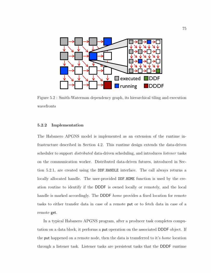
75
executedrunning
DDFDDDF
Figure 5.2 : Smith-Waterman dependency graph, its hierarchical tiling and execution
wavefronts
5.2.2 Implementation
The Habanero APGNS model is implemented as an extension of the runtime in-
frastructure described in Section 4.2. This runtime design extends the data-driven
scheduler to support distributed data-driven scheduling, and introduces listener tasks
on the communication worker. Distributed data-driven futures, introduced in Sec-
tion 5.2.1, are created using the DDF HANDLE interface. The call always returns a
locally allocated handle. The user-provided DDF HOME function is used by the cre-
ation routine to identify if the DDDF is owned locally or remotely, and the local
handle is marked accordingly. The DDDF home provides a fixed location for remote
tasks to either transfer data in case of a remote put or to fetch data in case of a
remote get.
In a typical Habanero APGNS program, after a producer task completes compu-
tation on a data block, it performs a put operation on the associated DDDF object. If
the put happened on a remote node, then the data is transferred to it’s home location
through a listener task. Listener tasks are persistent tasks that the DDDF runtime
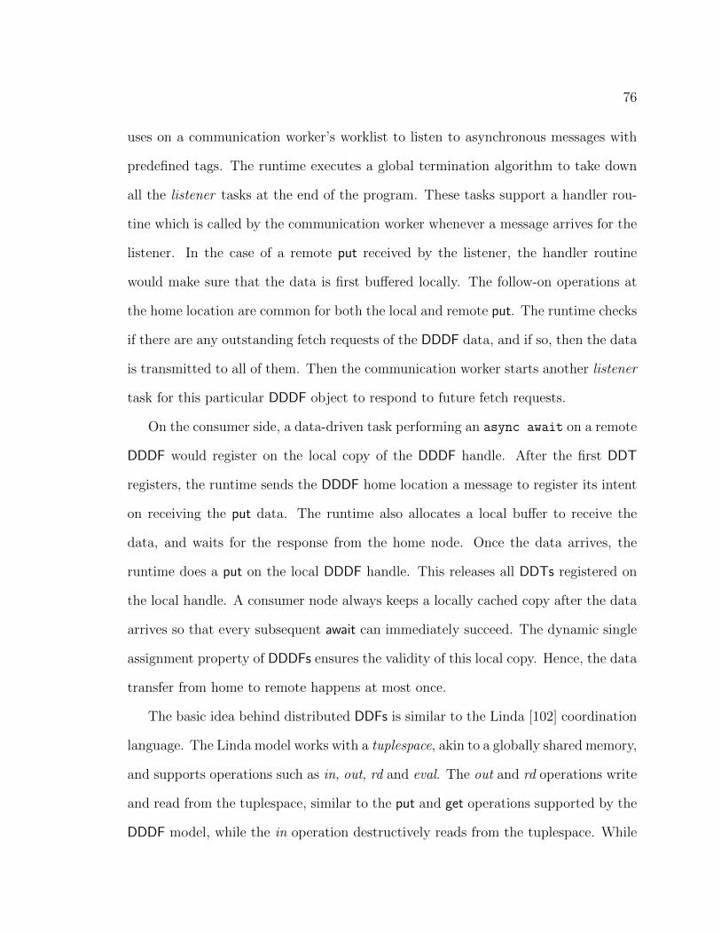
76
uses on a communication worker’s worklist to listen to asynchronous messages with
predefined tags. The runtime executes a global termination algorithm to take down
all the listener tasks at the end of the program. These tasks support a handler rou-
tine which is called by the communication worker whenever a message arrives for the
listener. In the case of a remote put received by the listener, the handler routine
would make sure that the data is first buffered locally. The follow-on operations at
the home location are common for both the local and remote put. The runtime checks
if there are any outstanding fetch requests of the DDDF data, and if so, then the data
is transmitted to all of them. Then the communication worker starts another listener
task for this particular DDDF object to respond to future fetch requests.
On the consumer side, a data-driven task performing an async await on a remote
DDDF would register on the local copy of the DDDF handle. After the first DDT
registers, the runtime sends the DDDF home location a message to register its intent
on receiving the put data. The runtime also allocates a local buffer to receive the
data, and waits for the response from the home node. Once the data arrives, the
runtime does a put on the local DDDF handle. This releases all DDTs registered on
the local handle. A consumer node always keeps a locally cached copy after the data
arrives so that every subsequent await can immediately succeed. The dynamic single
assignment property of DDDFs ensures the validity of this local copy. Hence, the data
transfer from home to remote happens at most once.
The basic idea behind distributed DDFs is similar to the Linda [102] coordination
language. The Linda model works with a tuplespace, akin to a globally shared memory,
and supports operations such as in, out, rd and eval. The out and rd operations write
and read from the tuplespace, similar to the put and get operations supported by the
DDDF model, while the in operation destructively reads from the tuplespace. While

77
the DDDF model is based on the single assignment property of data objects, Linda
allows multiple assignments. This causes a complication for the Linda runtime as
data needs to be coordinated by a runtime manager process. For example, an out
operation broadcasts that write to all the processors. Also, without the support for
data distribution function like the DDDF model, Linda’s performance comes at the
cost of communication bandwidth and local memory.
5.2.3 Results
Habanero APGNS provide high programmability where simple extensions to existing
shared memory programs can create a scalable distributed memory application. We
introduced a simple Smith-Waterman benchmark in section 5.2.1 and here we show a
hierarchically tiled implementation of the benchmark. This implementation performs
hierarchical tiling as in Figure 5.2. This allows us to tune granularity to minimize
communication for the outer-most tiling and to minimize intra-node task creation
overhead for the inner most tiling, while retaining sufficient parallelism at both levels.
An outer tile consists of a matrix of inner tiles, and three DDDFs. On Figure 5.2,
we show an enlarged outer tile consisting of a matrix of inner tiles. To minimize
communication, the DDDFs for the outer tile are the right-most column, the bottom-
most row and the bottom-right element, since these are the edges of a tile visible
to neighboring tiles. Similarly, an inner tile encapsulates a matrix of elements and
three shared memory DDDFs to represent the intra-node visible edges of an inner tile.
Given this representation of the dynamic programming matrix, we have exposed both
the inter-node and intra-node wavefront parallelism through registering neighboring
tiles’ distributed and shared memory DDDFs respectively.
On Figure 5.3, we present a scaling study of the implementation mentioned above.

78
8 16 32 64 96
2 Cores 1955.09 942.67 479.40 258.05 192.79 4 Cores 668.94 336.27 184.07 109.53 86.57 8 Cores 294.96 155.20 87.55 49.98 37.01 12 Cores 192.30 102.16 57.18 32.85 24.39
20
200
2000 log Time (s)
Nodes
SmithWaterman Scaling
2 Cores 4 Cores
8 Cores 12 Cores
Figure 5.3 : Scaling results for Smith-Waterman for 8 to 96 nodes with 2 to 12 cores
Our sequences are of length 1.856M and 1.92M, giving us the dimensions for our
matrix. We chose tile sizes 9280 by 9600 for outer tile sizes for a matrix of 200 by
200 tiles.
We chose this tile size to ensure the number of wavefronts provides sufficient
slackness with respect to the number of nodes. The top left and the bottom right
sections of the matrix do not provide sufficient parallelism and as their size passes
beyond a minute fraction, it constrains parallelism due to Amdahl’s law. Since the
number of parallel tasks at any given time is the size of an unstructured diagonal (as
in figure 5.2), to provide enough parallelism, we need to have at least a factor of the
number of nodes on most diagonals. The same logic applies to the inner tiles too,
and we have chosen 290 by 300 tile sizes to have 32 by 32 tiles.

79
Using a distribution function, DDF HOME, for DDDFs, we implemented a tiling
strategy as follows. Every proper diagonal is measured in size and every contiguous
chunk of that diagonal is assigned to nodes iteratively. This provides a mapping to
nodes which for each node creates bands perpendicular to the wavefront and leads to
less communication.
Given a fixed number of cores we observe speedups in the range 1.7 − 2 when
doubling the number of nodes until 64 nodes. This trend is hampered on the 64 node
to 96 node jump because, because the first and last 96 diagonals do not have enough
parallelism for 96 nodes, where the total number of diagonals is 399.
Given a fixed number of nodes, we observe speedups in the range 2.2-2.9 for 2 to
4 core case, since one of the workers is designated as a communication worker. The
range is between 5.2-6.6 for 2 to 8 cores (for 1 to 7 computation workers), and 7.9-10.2
for 2 to 12 cores (for 1 to 11 computation workers).
5.3 Habanero-C Tuning Framework
The software challenges in future extreme-scale systems are compounded by the need
to support new workloads and application domains that have traditionally not had
to worry about large scales of parallelism in the past. Adapting these applications to
run optimally on extreme-scale systems would be beyond the expertise of program-
mers with only domain knowledge. As a result, a tuning expert with detailed system
knowledge will extract superior performance from the application. However, with-
out a detailed knowledge about the application domain, the tuning expert will find
it difficult to be highly productive. We aim to bridge this gap between the tuning
and domain experts by forming a tuning framework which makes it possible for the
tuning expert to make performance optimizations without much domain knowledge.

80
The considerations of parallelism, load balancing and locality, are separate from con-
siderations of the application domain and algorithms. When creating or modifying
the application algorithms, there are no explicit parallel constructs to worry about.
When thinking about mapping to the platform, there is no need to wade through the
application semantics. The tuning framework targets performance benefits from spa-
tial and temporal locality of tasks in a dynamic task parallel environment. With the
cost of moving data projected to become increasingly prohibitive in future, the per-
formance of a system will be increasingly sensitive to the the spatio-temporal locality
of tasks which access common data blocks. Spatial locality of tasks mean execution of
parallel tasks on parallel processors with a shared memory structure. Spatial locality
should also be in combination with task temporal locality for tangible performance
benefits due to the limited size of memory units in future memory designs.
5.3.1 Hierarchical Place Trees for Spatial Locality
Future extreme scale systems are expected to have computing nodes containing thou-
sands of processor cores and designing a memory subsystem for such an architecture is
great challenge. It will not be feasible to build a large DRAM-like memory structure
shared among all processor cores mainly due to bandwidth and power limitations.
Current indications point towards an architecture with deep memory hierarchies with
computing cores provided with fast local limited memories. Data accesses latencies
are expected to dramatically increase as memories further up the hierarchy are used.
Exploiting data locality in parallel programming on those complex is a challenge
for users. Prior compiler and runtime research has proved that, in sequential code,
lots of data locality optimization can be achieved by advanced data flow analysis
and sophisticated code transformation techniques, such as polyhedral model. Efforts

81
to bring those techniques into parallel programming needs supports from both the
system modeling and the runtime. We present our approach of modeling complex
memory hierarchy of various computing systems as a hierarchical place tree (HPT).
HPTs provide an abstraction powerful enough to exploit locality at each level in the
memory hierarchy, without compromising performance. Finally, it is a step towards
performance tuning optimizations with explicit data locality control on exascale sys-
tems.
HPTs in Habanero-C abstract the underlying hardware using trees, which closely
model the memory hierarchy of the node. It allows the program to spawn tasks at
places, which for example could be cores, groups of cores sharing cache, nodes, groups
of nodes, or other devices such as GPUs or FPGAs. Figure 5.4 shows an example
HPT implementation structure of a Intel Xeon Dual Quad Core machine. A single
node of this machine has a shared DRAM for all 8 processor cores. The chip has
2 sockets with 4 processors in each socket. The processors in each socket share a
single L3 cache. Within each socket two groupings of 2 processors share a L2 cache.
Each processor core comes with it own local L1 cache. The HPT structure shown in
Figure 5.4 implements this memory hierarchy as a 3 level binary tree. Every node in
the tree refers to a particular instance of the memory hierarchy. The leaf level nodes
refer to the L1 cache of each processor core. The levels above the leaf refer to the L2
and L3 caches in the machine with the root of the tree referring to the shared DRAM.
In the HPT each node of the tree is an unique place. Places are usually numbered
starting at the root and proceed in a breadth first manner.
The Habanero-C language uses the AT clause with the async statement to spawn
a task at a place. The AT clause takes a place argument. A typical usage is:
async AT(p) 〈stmt〉
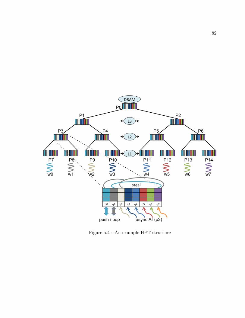
82
q0 q1 q2 q3 q4 q5 q6 q7
P0
P1 P2
P3 P4 P5 P6
P7 P8 P9 P10 P11 P12 P13 P14 L1
w0 w1 w2 w3 w4 w5 w6 w7
steal
push / pop async AT(p3)
L2
L3
DRAM
Figure 5.4 : An example HPT structure

83
This spawns the new task with body 〈stmt〉 at the place p. This way HPTs allow for
explicit control of task locality on the system with the intention of shared data reuse.
Worker threads, which are proxy for processor cores, are associated with leaf nodes
of the HPT. A leaf place can have one or more worker threads attached. When a
leaf place has only one worker thread attached, the node is usually the local exclusive
memory of that processor, such as the L1 cache. However, if a place node in the HPT
has multiple children, such as an internal node, or multiple workers on the leaf node,
then, that place usually refers to a shared memory level. A task spawned at such a
place will be executed by the worker thread associated with the subtree under that
node. For example, a task that is put in place p3 can be executed by either worker
thread w0 or w1. The main idea of the HPT is to limit access, as much as possible, to
tasks to the set of worker threads in the subtree that share some memory hierarchy.
However, a task placed in place p7 can only be executed by worker w0. The HC
runtime provides APIs that help navigate the HPT structure and get a handle on a
place.
5.3.2 Tuning Framework for Spatio-Temporal Task Locality
The Habanero tuning framework is a set of API’s that can guide the execution of
a task parallel program written in Habanero-C. The goal of the tuning framework
is to support a tuning language or specification that can target these API’s at the
assembly-language level. This framework will use a separate tuning specification
with distinct capabilities but used to complement the domain specification. Multiple
tuning specifications can be associated with the same domain specification to target
different in optimization goals on a target platform architecture. The foundation of
the tuning specification is to identify computations that should be close in both time

84
(a) Target Platform (b) Tuning Tree
Figure 5.5 : Tuning tree of queues matches the target platform structure
and space. Closeness is identified by hierarchical affinities among computations and
data. This allows the indication of relative degrees of locality. The basic concept of
the tuning specification is the affinity collection, a group of steps, implemented as
tasks, that the tuner suggests should be executed close in space and time. Hierar-
chical affinity groups allow the specification of relative levels of affinity, with tighter
affinity at lower levels. Computations that touch the same data will not benefit from
locality if they are too far apart in space or time. Hierarchical affinity groups are the
tuning mechanism for indicating computations that must be proximate in both time
and space. The tuning API provides the tuner with a mechanism to influence the
scheduling of parallel tasks to take advantage of the space and time locality benefits.
The tuning execution model is based on a representation of the target platform, as
shown in Fig. 5.5a. We currently assume that the platform is hierarchical, although
the model can be adapted to other structures as well. The platform description names
each level, for example, Level1, Level2, etc. or it might be address space, socket, core,
etc. We distinguish between two components of the runtime: the tuning runtime and

85
the domain runtime. The tuning runtime serves as a staging area for the execution
of steps in the domain component. A tuning action is defined for each affinity group.
Tuning actions specify the low-level processing for that group in the tuning tree. The
tuning actions control the flow of work to the domain runtime. The tuning tree has
the same shape as the platform tree. There is a work queue associated with each node
in the tuning tree, shown in Fig. 5.5b. The items in the queue are either static affinity
groups/steps or dynamic instances of affinity groups/steps. Each queue contains work
that is ready for an action to be performed (such as moving down the tree) and work
that is not ready. The tuning runtime system selects from a queue the ready work
item(s) that are nearest the head of the queue. Large static outer affinity groups start
at the top of the tuning tree. As an affinity group is moved down a level in the tree, it
will be decomposed into its components. Since components of a group at some node
only move to children of that node (there is no work stealing), they have a tendency
to remain close in the platform, in that nodes in the tuning tree correspond to nodes
in the platform tree. Figure 5.6 shows an example tuning action for unpacking a
group and moving it down the tuning tree. to execute a step, it has to get released
from the tuning runtime onto the domain runtime. The set of tuning APIs that are
currently supported are:
TUNING PUT AT ROOT (group, args)
places a group or step at the root of the tuning tree
TUNING MOVE DOWN (group, args)
moves a group or step down unmodified one level in the tuning tree
TUNING DISTRIBUTE AMONG CHILDREN ( nargs, group, args )
unpacks a group and distributes the components among the children of the node

86
(a) Tuning group of steps (b) Tuning unpack and move down
Figure 5.6 : Tuning action to unpack a group and move down the steps
TUNING RELEASE STEP ( step, args )
places the step onto the domain runtime for execution
5.3.3 HPT Implementation
The HPT structure for a Habanero-C program is specified as an XML input document.
If the HPT input is not specified, the HC runtime assumes a single place consisting of
all the workers. Figure 5.7 shows the XML file structure for the Intel Xeon Dual Quad
Core machine HPT shown in Fig. 5.4. The nested structure of the place attributes
show the tree hierarchy and the num values replicate the subtree on each child of a
node.
The Habanero-C work-stealing runtime, described in Section 3.2, takes advantage
of the HPT hierarchy to preserve locality when executing tasks. In our design, any
worker can push a task at any place in the HPT. Each place in the HPT contains one
deque per worker. For example, Figure 5.4 shows each place having 8 deques, q0 to
q7, for the 8 workers, w0 to w7. This gives each worker the ability to perform non-
synchronized push and pop operations on their own deques at each place. The steal

87
<?xml version="1.0"?>
<!DOCTYPE HPT SYSTEM "hpt.dtd">
<HPT version="0.1" info="Dual quad -core Intel Xeon">
<place num="1" type="mem">
<place num="2" type="cache"> <! sockets >
<place num="2" type="cache"> <! L2 cache >
<place num="2" type="cache"> <! L1 cache >
<worker num="1"/>
</place >
</place >
</place >
</place >
</HPT >
Figure 5.7 : An example of a HPT XML description

88
operations, however, have to be synchronized. The HC runtime limits pop or steal
operations at a place to only the workers in the subtree of that node. For example,
workers w0 and w1 only are permitted to perform pop and steal at place p3. Any of
workers w0 to w7 are permitted to push at p3.
In the current scheduling heuristic employed by the HC runtime a worker starts
the search for an executable task at the leaf place it is attached to. It first tries to
pop tasks on its own deque in the place. If it fails to pop a task, it tries to steal from
the other deques in the same place. When a worker runs out of work at a place, it
tries to look for work at the parent place. The worker traverses the path from leaf
to the root in search of work. After any successful pop or steal, the work executes
the task and then resumes the search from it’s own deque on the leaf place, where it
started from initially. The HC runtime makes sure that the worker threads are bound
to the appropriate cores to resemble the correct sharing of the memory hierarchy.
One drawback of this design is the O(n2) number of deques on the system, where
n refers to the number of workers. Although, this design provides non-synchronized
push operation of a worker at any place, the overhead of searching for work increases.
Each of n workers will search for work on O(n log n) deques. We are currently
working on more efficient designs that will minimize this overhead without making
all workstealing operations synchronous. One of design choices being considered is to
maintain a deque per place for only those workers that are in the subtree and keep
a separate deque for all other workers. So, if a worker is trying to push at a place
while being outside the subtree of that place, that push would be a synchronous one.
This rationale is based on application experiences where it was observed that the
frequency of pushes to a place from a worker external to its subtree is relatively lower
than pushes from within the subtree.

89
Scalable Deque Implementation
The current HC implementation requires all deques be initialized at the start of the
program to a fixed size. The size of the deques may be set by the user (with the
−deqsize runtime option) to be the maximum value that will fit all tasks than can
potentially exist on one deque at any given instant. This is a problem because it may
not always be possible to know this number before running the program. As a result,
the user may try to over-provision the deque with a unnaturally large size to prevent
deque overflow. This problem is exacerbated by the use of HPTs. We have seen from
our design of the HPT that every place contains one deque per worker, meaning O(n2)
deques for n workers. If large fixed sized deques are used, this would prove to be a
severe scalability bottleneck for future extreme scale systems which are expected to
have O(103) processor cores per node.
This problem can be solved if the HPT is initialized with small resizable deques
which can grow and shrink during program execution. It would avoid having the user
to guess the largest deque size to avoid deque overflow. Further, one large fixed size
need not be applied uniformly on all deques. On extreme scale systems, although
there would be a high number of deques, the space complexity would be greatly
improved. An efficient resizable deque solution will have two key requirements:
• Wait-free deque resize - We want to avoid freezing the deque when resizing so
that concurrent steals are possible.
• Zero data copy - We want to avoid copying the whole deque for faster and
reliable resizing.
The HC deque described in Section 3.2 supports push, pop and steal operations.
The deques contain a head and tail to index both ends. Our solution for the resizable
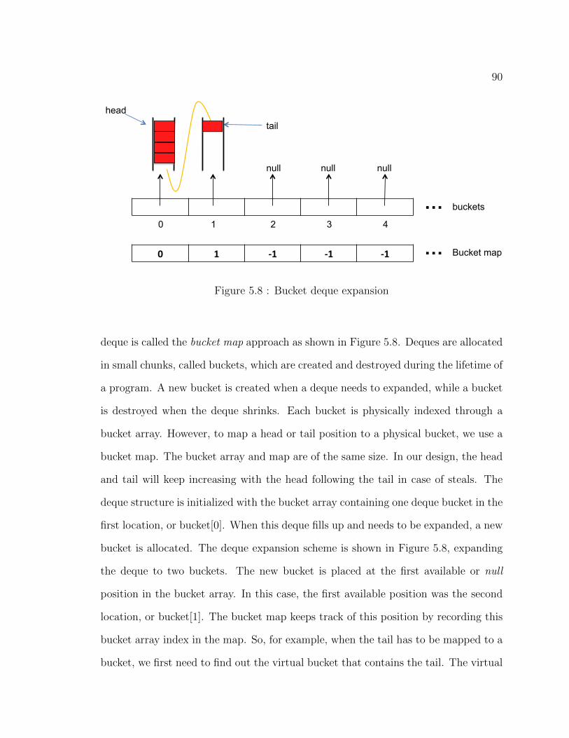
90
tail
null null null
buckets …
head
0 1 -‐1 -‐1 -‐1 Bucket map … 0 1 2 3 4
Figure 5.8 : Bucket deque expansion
deque is called the bucket map approach as shown in Figure 5.8. Deques are allocated
in small chunks, called buckets, which are created and destroyed during the lifetime of
a program. A new bucket is created when a deque needs to expanded, while a bucket
is destroyed when the deque shrinks. Each bucket is physically indexed through a
bucket array. However, to map a head or tail position to a physical bucket, we use a
bucket map. The bucket array and map are of the same size. In our design, the head
and tail will keep increasing with the head following the tail in case of steals. The
deque structure is initialized with the bucket array containing one deque bucket in the
first location, or bucket[0]. When this deque fills up and needs to be expanded, a new
bucket is allocated. The deque expansion scheme is shown in Figure 5.8, expanding
the deque to two buckets. The new bucket is placed at the first available or null
position in the bucket array. In this case, the first available position was the second
location, or bucket[1]. The bucket map keeps track of this position by recording this
bucket array index in the map. So, for example, when the tail has to be mapped to a
bucket, we first need to find out the virtual bucket that contains the tail. The virtual

91
tail
null null null
buckets …
head
0 1 0 -‐1 -‐1 Bucket map … 0 1 2 3 4
Figure 5.9 : Bucket deque reuse after contraction
bucket index on the bucket map provides the physical index into the bucket array for
the actual physical bucket.
Now, say the steals on deque has reduced the deque size down to one bucket after
it had expanded to two buckets. So, the bucket in position 0 of the bucket array is
no longer used and it is freed. However, when the deque needs to be expanded once
more, the new bucket can now be placed in bucket array position 0. This bucket
reuse scheme is shown in Figure 5.9. The tail now has to map to the new location of
the physical bucket via the bucket map. Hence, we can see that the virtual bucket
index of the tail in the bucket map, which is 2, now contains the index 0, the actual
physical location of the bucket.
Algorithms 1 shows the implementation of the deque push operation. Here, we
can see how we use the deque tail (deq.tail) to identify the physical location of the
deque where the task will be pushed. Since, the tail increases infinitely, we divide that
number by the size of each deque bucket to get the virtual bucket number (vb) of the

92
Algorithm 1: Push operation for resizable deques
if deque is full then
expand(deq);
end
vb ← deq.tail / deq.bucketSize ; // virtual bucket
mapIdx ← vb % deq.mapSize ; // bucket map index
b ← deq.bucketMap[mapIdx] ; // physical bucket
deq.buffer[b][deq.tail % deq.bucketSize] ← entry ; // setup task
deq.tail++ ; // push task
tail. This virtual bucket number should have an entry on the bucket map. Since, the
map is limited in size, the virtual bucket number should wrap onto the bucket map.
The deque buckets cannot be larger than what the bucket map supports. Hence, the
virtual bucket remainder from the map wrap give us the bucket map index (mapIdx).
We get the physical bucket (b) from the bucket map. Now, we are able to index onto
the physical bucket where we place the task (entry). We complete the push operation
by incrementing deque tail. For better efficiency divides and remainder operations
can be replaced by shifts and & operations if bucket and map sizes are maintained
at powers of two. The pop and steal operations, described in Section 3.2.3 have been
similarly modified to use the bucket map approach. When the number of slots on the
bucket array are completely full, the bucket array and bucket map will doubled and the
data copied from the old arrays. Doubling the size keeps the modulo indexing same on
the bucket array and map which keeps the concurrent steals going [78]. We currently
do not free the old bucket array and map because it provides a way for threads to
recover after being suspended while stealing. Chase and Lev [78] use a similar scheme

93
Figure 5.10 : Releasing steps from tuning tree to domain tree
but the amount of memory that is not freed in our algorithm is drastically less than
theirs. Consequently, in our algorithm the amount of data copied will be an order of
magnitude less while maintaining wait-free deque expansion and contraction.
5.3.4 Tuning Tree Implementation
The tuning runtime implementation is based on the DDF model, introduced in sec-
tion 3.2.2. In this model, a consumer task can be created with an await clause to
specify the incoming dependence. A producer task can satisfy an outgoing depen-
dence by performing a put on that dependence variable. A tuning specification is
currently translated manually to Habanero-C data-driven tasks (DDTs) for execu-
tion. We use DDTs to specify the tuning actions, and DDFs to specify the tuning
dependences for groups and steps in the program.
We implemented the platform tree described earlier using Habanero-C’s Hierar-
chical Place Trees. In our preliminary implementation, we use the HPT configuration
as the tuning tree. An HPT configuration is specified by an XML file. This file can

94
specify a node (or place) in the HPT to be a tuning place. These tuning places
contain a special kind of task queue used exclusively for tuning. When a group or
step is pushed down a path in the tree, as specified in a tuning API, it gets enqueued
into the tuning queue at that child place. When a step get released from the tuning
tree, it gets immediately executed. HPT places also contain double-ended queues
(deques). Any task that is not created by the tuning runtime gets scheduled at the
deques in the HPT places. We have modified the Habanero-C runtime scheduler to
perform both tuning actions and domain (user code) scheduling. We handle all tun-
ing tasks, both groups and steps, in the tuning runtime scheduler. All other tasks in
the application are executed in the domain runtime scheduler. A worker thread first
searches for domain work. It executes all tasks in its own deque before searching for
more domain tasks to steal from other workers. If the worker fails to find any domain
work, it switches to the tuning scheduler. The tuning scheduler starts searching for
work at the leaf node and moves up to the root. When it finds a tuning task at any
node in the path from leaf to root, the worker locks the queue, executes the tuning
task, unlocks the queue and finally switches over to the domain runtime. The locking
of the queue ensures that the tuning actions in a tuning queue is completed in the
order that they were enqueued in. Maintaining the order is critical for maintaining
temporal locality. Figure 5.10 shows the action of releasing steps from the tuning
runtime to the domain runtime. The tuning tasks are based on a set of tuning APIs.
As mentioned before, the tuning APIs can push a group or step down the tuning
tree. This operation involves pulling the tuning task from a nodes tuning queue and
pushing it onto a child nodes tuning queue. These operations are synchronized with
locks to handle concurrent enqueues and dequeues.

95
5.3.5 Results
In this section we look at some preliminary results of our experiments using the
HPT. We use the Cholesky decomposition benchmark for our experiments. Cholesky
decomposition is a dense linear algebra application that exploits loop, data, task and
pipeline parallelism. The base version of this benchmark used in our experiments is
implemented using data driven tasks [77]. This implementation of the benchmark
runs a tiled version with each tile on every iteration being executed by a unique
task. This data driven implementation enables an unconstrained execution of tasks
that is not restricted by a structured task parallel model. Tasks get scheduled once
their dependencies are satisfied. Figure 5.11 shows the dependence structure in a
tiled Cholesky execution of one particular iteration instance. The iterations proceed
with a pivot tile computation on the diagonal. The pivot tile in one iteration plane
computes the serial Cholesky step. Once that is done, the trisolve steps are able to
run on the pivot column. The trisolve computation enables the rest of the update
computations tiles in the iteration. Each tile also had a dependence on itself in the
subsequent iteration. We have not shown that dependence in the figure.
We run our experiments on a single node of the DaVinCi cluster at Rice University.
Each computing node consists of an Intel Westmere processor with 12 cores running
at 2.83 GHz. The 12 cores are divided into two sockets with 6 cores in each. Each
socket consists of a shared L3 data cache of 6MB. Every cores has it’s own local
L1 and L2 data caches of size 32KB and 256KB respectively. The only data reuse
within an iteration is from the reuse of the trisolve tile by the update tiles. However
as shown in Figure 5.11 that all the update computations in one row uses all the
trisolves until that row. As a result, trying to localize the computations to some part
of the memory hierarchy would be difficult for the trisolve steps. So, our strategy for

96
Cholesky
Trisolve Update
Figure 5.11 : Cholesky decomposition dependences

97
9.572
8.235 6.945 6.609 6.573
6.851 7.258
8.278
11.595
6.751 6.122 6.329 6.331 6.361 6.865
7.549 8.393
11.789
0.000
2.000
4.000
6.000
8.000
10.000
12.000
20 25 40 50 60 75 100 125 150
Time (s)
Tile Size
Cholesky 6000x6000
Base HPT
Figure 5.12 : Cholesky decomposition execution times for various tile sizes
exploiting data reuse is across iterations. We ensure that tiles in successive iterations
are able to execute on the same socket so that they can benefit from L3 cache reuse.
Also, since our experimental platform has two sockets, we divide the tiles on each
iteration evenly between the sockets so that we don’t lose much parallelism. Let us
recall that our current HPT scheduling heuristic does not allow a worker to explore
a new subtree while for searching stealable tasks. So, we lose some bit of parallelism
due to the slight imbalance between sockets when the division is not perfect.
Figure 5.12 compares performance of the base version against the HPT version.
We show execution times for varying tile sizes. In general, the HPT version performs
better than the base version. The slight crossover in performance noticed past tile
size of 75 is attributed to the loss of parallelism resulting from a higher tile size. This
is due to our scheduling heuristic which does not allow a worker to search for work in

98
a different subtree. It can be seen that the execution times point out an best tile size
for each version of the benchmark. However, the best tile sizes are different the base
and HPT versions. The best time achieved by the base version is on a tile size of 60
and a time of 6.57 seconds. The HPT version on the other hand achieves it’s best time
of 6.12 seconds on a tile size of 25. This shows approximately 7% speedup achieved
by the HPT version. Investigating this result further we were able to identify that the
benchmark was compute bound. We found only 15% of execution time was actually
being spent on memory accesses. In light of our finding, we believe that 7% speedup
is about the maximum that can be achieved by any HPT version that optimizes on
cache reuse.
Past work by Husbands and Yelick [103] proposed that for the LU factorization
benchmark a prioritization of the tasks on the row and column of a pivot, called
panel factorization, leads to better performance as it exposes more concurrency in
the application. A similar approach will help Cholesky factorization as well but the
current HPT model does not (yet) have a notion of priority for tasks. However,
the tuning framework (with a modification of the scheduling heuristic) can enforce
priorities on tasks execution. As an example, if high priority tasks arrive in the tuning
tree when the domain runtime is already working on a set of tasks on the HPT, the
scheduler should be able to pick up those tasks before completing all pending tasks.
The tuning tree can keep a queue of high priority tasks for each worker. This requires
a modification in the scheduler to check the tuning tree before it tries to pop a task
from a deque in the HPT. In this way, both priority and locality can be controlled by
the tuning expert. This approach will be considered in future work.
In this section we will also present results of our experiences with the tuning frame-
work. We have experimented with two applications, namely, Cholesky factorization

99
and Rician denoising. We will present results of the Cholesky tuning experiment fol-
lowed by the Rician denoising results. Our experimental platform is a 12-core Intel
Westmere processor that contains two sockets with 6 cores each and a shared L3 cache
in each socket. The tuning tree consists of 3 levels, with the root node as the DRAM
memory. The second level contains 2 nodes to represent the 2 sockets. Each node in
the second level had 6 children to represent the individual cores in the socket.
Tuning Cholesky Factorization
We have implemented multiple tuning specifications for the Cholesky Factorization
program written in HC. While our current transformations from tuning specifications
to DDTs are performed by hand, an implementation of a translator that will automat-
ically generate DDTs from the tuning specification is a straightforward candidate for
future work. We created an outer level group called GroupC, as shown in Figure 5.13.
GroupC contains the Cholesky step and another group called GroupTU, which con-
tains the trisolve and update steps. For example, a tuning function for the Cholesky
group described above that releases the Cholesky step to the Habanero-C runtime for
execution, while distributing the GroupTU among children can be written simply as:
We present two sets of experiments, namely Set1 and Set2. In the first tuning
specification (Tuning1) of Set1, we the placed the GroupC instances on the root node
queue of the tuning tree. When a worker pulled a GroupC instance out of the root,
it placed the Cholesky step for execution on either child. It then distributed the
GroupTU instances among the two sockets. A worker that picked up a GroupTU
would then unpack and execute the trisolve and update steps within the socket. The
second tuning specification (Tuning2) of Set1 moved a GroupC instance down a child
before unpacking GroupC. Subsequently the Cholesky step is placed in the socket

100
void groupC(void * args) {
int k = (( cholesky_args *)args)->k;
int numTU = numTiles - (k + 1);
TUNING_RELEASE_STEP(cholesky_step , args);
TUNING_DISTRIBUTE_AMONG_CHILDREN(numTU ,
groupTU , args_set[k]);
}
Figure 5.13 : Tuning actions on GroupC, the outer level group in Cholesky
level node while the GroupTU instances are distributed among the 6 children. This
tuning restricts the execution of each instance of GroupC, that is, the Cholesky step
and all the GroupTU instances, containing the Trisolve and Update steps to execute
inside one socket. Further, each GroupTU instance executes only on one core. The
Set1 experiments were performed on a 2000x2000 matrix and the results are shown
in Figure 5.14. The results indicate that Tuning2 slowed down by almost a factor of
2 with respect to Tuning1, while the idleness of Tuning2 was 14.7× that of Tuning1.
The reason for the slowdown in Tuning2 was that the schedule was constrained in
parallelism when the groups were pushed down to one more level in the tuning tree.
Tuning1 runs faster but Tuning2 would consume less power. This result implies that
a tuning specification can affect performance and power at the same time.
In our second set (Set2) of experiments, we keep Tuning1 from Set1 which per-
forms the row grouping of trisolve and updates as the first tuning specification. The
second and third tuning specification would group some TU rows while others were
grouped in columns. This division among the row and column grouping could ei-
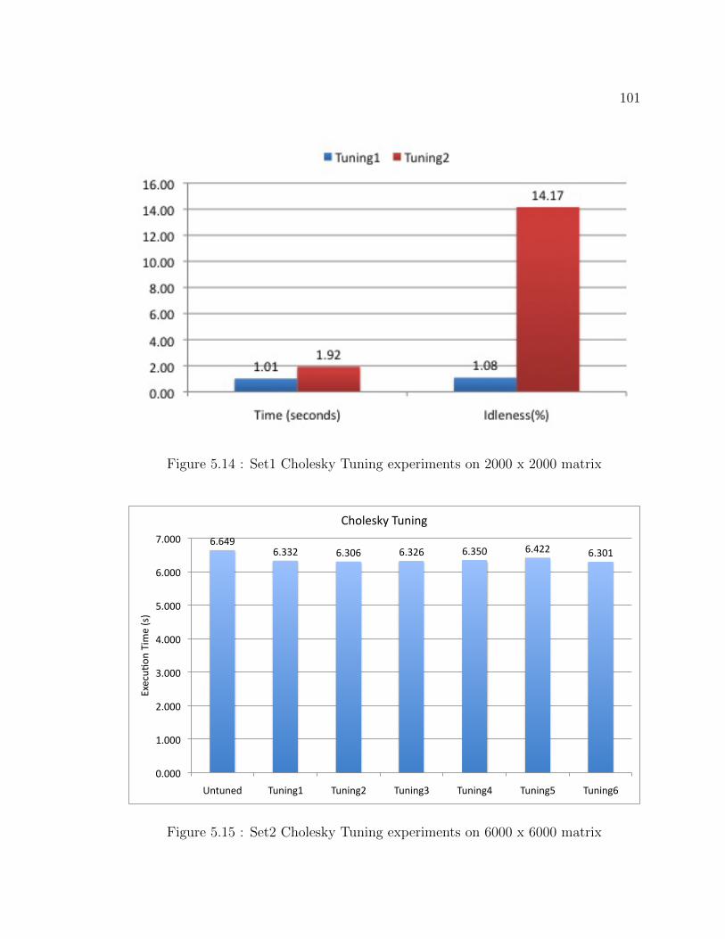
101
Figure 5.14 : Set1 Cholesky Tuning experiments on 2000 x 2000 matrix
6.649 6.332 6.306 6.326 6.350 6.422 6.301
0.000
1.000
2.000
3.000
4.000
5.000
6.000
7.000
Untuned Tuning1 Tuning2 Tuning3 Tuning4 Tuning5 Tuning6
Execu8
on Tim
e (s)
Cholesky Tuning
Figure 5.15 : Set2 Cholesky Tuning experiments on 6000 x 6000 matrix

102
ther dynamically adjusted with increasing number of iterations or statically assigned.
Tuning2 does the dynamic adjustment while Tuning3 does the static assignment.
Tuning4 tries to improve Tuning2 by coarsening the groups towards the tail end of
the iterations in order to benefit from granularity of the steps. Tuning5 and Tun-
ing6 simply puts all tasks at the socket level, the difference being that Tuning6 does a
chunked distribution of the tiles. Results of the experiments are shown in Figure 5.15.
Our untuned baseline version is an optimally tiled version. Tuning tries to achieve a
better schedule for the execution of the tiles. We see that our maximum speedup of
5.16% is obtained from Tuning2. As mentioned earlier, speedups over an already tiled
compute bound application will be limited. Comparing to the speedups obtained in
the HPT experiment, the tuning shows a slightly lesser speedup. We attribute this
to the overhead of maintaining the tuning scheduler. The tuning however is able to
perform these optimizations without modifying the original application which was
not the case with the HPT experiment.
Tuning Rician Denoising
In this section, we present the tuning experiments for the Rician Denoising appli-
cation, which is used as part of the medical imaging pipeline in the CDSC project.
This application performs a five-point stencil computation on every tile in parallel.
This computation is done iteratively until a convergence value is reached. Figure 5.16
shows the dependencies between the various steps both within and across iterations.
For example, uDiffCompute reads uData stencil elements from the previous iteration
while gCompute, ugCompute and rCompute read data only on the current iteration.
uCompute reads data both from the previous and current iteration. This complicated
dependence pattern can be simplified by grouping the steps as shown in Figure 5.17.

103
Figure 5.16 : Rician denoising dependencies
Figure 5.17 : Grouped rician denoising steps

104
Figure 5.18 : Pyramid computation for tiles in successive iterations
19.66 20.16
35.48
55.26
16.86 16.91 15.93 16.04
0.00
10.00
20.00
30.00
40.00
50.00
60.00
64 60 40 32
Time (s)
Tile Size
Rician Denoising matrix size (7680x7680) and 30 itera<ons
orig untuned precompute pre+coreBlock
pre+coreBlock+wave pre+pyramid (unordered) pre+pyramid (ordered)
Untuned best Tuned best
Figure 5.19 : Rician Denoising performance comparison of untuned vs tuned

105
In our tuning specification we call this the precompute group. Starting with this
precompute specification, we formulated two tuning strategies. In the first strategy,
we make simple iteration-wise tile executions. The ”pre+coreBlock” tuning uses
the precompute step and schedules a block of tiles in each iteration on each core.
The matrix rows are first divided into sockets, followed by division into cores. The
”pre+coreBlock+wave” tuning has each core trying to execute the scheduled set of
tiles in a wavefront pattern. The second tuning strategy uses a pyramid computation,
in which the motivation is to reuse tiles computed at current iteration in the next
iteration, as shown in Figure 5.18. Since the stencil computation reads data from
neighboring tiles, the plane of computation in successive iterations that use the same
tiles will be decreasing. Layering these successive diminishing planes on top of each
other, we get a visualization of a pyramid. In order to to benefit from the tile reuse,
the whole pyramid must fit in the socket level shared L3 cache. The ”pre+pyramid
(unordered)” tuning schedules the pyramids onto the sockets in unordered fashion.
In the worst case, every worker may pull a different pyramid onto the socket. The
”pre+pyramid (ordered)” tuning orders the pyramids such that a new pyramid is
brought in only when the current pyramid is close to being done. Figure 5.19 shows
the results of the tuning experiments and compares against the untuned version.
Overall, the best tuned time we got was 15.93 seconds. Compared to the best untuned
time of 19.65 seconds, the best tuned version shows an improvement of 20%. It is
interesting to note that the ordered computation on the pyramid tuning produced the
best result. In that tuning we hold back execution of steps to execute them together
and that proves to be the better strategy than the unordered one. Hence, this is
a proof of concept that temporal locality of tasks will make a positive impact on
performance.

106
Past work for optimizing stencil computation include cache-oblivious algorithms,
auto-tuners and domain specific stencil compilers [104, 105, 106]. They target data
reuse from trapezoidal computations, similar to the pyramid structure in our work.
The key difference is that the data reuse they target is specific to the cache hierarchy
of each processor, while our work aims to benefit from data reuse of the shared caches
through runtime co-scheduling of computations. For example, in our experimental
platform, the Pochoir stencil compiler [106], would optimize data reuse for L1 and L2
caches, where as our tuning framework gets reuse from the L3 cache that is shared
among the cores in a socket. For current stencil compilers, all shared cache reuse
is fortuitous. In our experiment, we used flat tile computations. Using trapezoidal
tiles instead, as generated by stencil compilers, would further improve our perfor-
mance. Hence, integrating stencil compilers and our runtime tuning framework will
be an important area of future work. Cache-oblivious algorithms target data reuse
through recursive decomposition of a regular computation space. In contrast, the
tuning framework is able to handle different types of computations at different levels
of the hierarchy. Cache-oblivious algorithms also are based on many assumptions
that may not hold for extreme-scale systems. For example, assumptions of an ideal
hardware cache model with inclusion property across hierarchies and an optimal re-
placement property will likely be replaced by software managed memory hierarchies
on extreme-scale systems. Cache-oblivious algorithms also assume computations on
homogenous CPU architectures and an empty cache before and after task execution.
Cache complexity of tasks are analyzed independently of other tasks without any co-
location analysis with the assumption that randomized workstealing does not change
asymptotic cache complexity. As discussed earlier, future extreme-scale systems will
be qualitatively different from these assumptions.

107
5.4 Summary
In this chapter, we have presented methods for controlling locality of compute and
data on shared and distributed memory systems. The HAPGNS model enables user
directed data distribution functions to optimize data layout on distributed systems.
Users can also use the HAPGNS model to take advantage of a distributed dataflow pro-
gramming model using distributed DDFs as a simple extension to the shared-memory
DDF model. Scalability results for the Smith-Waterman benchmark show the practi-
cality of this approach, which offers high programmability. We implemented the HPT
model for Habanero-C to affect spatial locality of computation tasks. We designed
a novel deque resizing algorithm to work with the HPT model. We also presented
a tuning framework for controlling spatial and temporal locality of computations at
the intra-node level. The tuning framework is integrated with the Habanero-C run-
time. Our experimental results with the tuning framework use the Rician denoising
application. We show a performance improvement of 19%-20% over an already par-
allel, tiled (for local caches) and load balanced execution on a fairly small system (12
cores) and a fairly shallow hierarchy (3 level caches - local L1 and L2, socket shared
L3) with today’s data movement costs. We anticipate even better improvements on
tomorrow’s systems with more cores, deeper hierarchies and higher ratios in the costs
of data movement vs computation.

108
Chapter 6
Task Synchronization for Iterative Computation
The Habanero-C dynamic task parallel language has the ability to express fine-grained
parallelism with the help of lightweight tasks. Tasks get executed by worker threads
that are governed by a runtime scheduling algorithm. The runtime scheduler ensures
load-balanced execution by using a work-stealing algorithm. Although the runtime
helps with efficient execution of parallel tasks, every runtime operation is considered
overhead for the application’s real work. This sounds counter-intuitive because users
usually do not notice these overheads relative to the actual amount of work when the
number of runtime operations are far less than the number of operations inside the
tasks. However, when the ratio of runtime operations to actual work operations is no
longer negligible, it could adversely affect the performance of the application. In other
words, application performance can be viewed as being sensitive to task granularity.
If the granularity is too small, it can cause time and space overheads due to the
large number of tasks in the system. In such a scenario, the runtime has to spend
more time scheduling these tasks and require more space storing them. Applications
written with deeply nested parallelism in the structured task parallel model, a smaller
granularity of computation may cause frequent task blocking leading to large runtime
overheads. In the data-flow task model, unbounded queue sizes may cause second
order effects such as non-uniform queue access latencies. If the granularity is too
large, it may cause loss of parallelism and lesser overlaps between computation and
data movement.

109
For iterative computations, tuning for task granularity will be a key process for
scalable performance on extreme-scale systems. Iteration spaces for computations can
very large for scientific applications. While it is possible to express every iteration as
a distinct task, the total number of tasks can very easily reach O(106) and higher for
a typical loop based computation. The runtime overheads for such a scenario would
be prohibitively high. One of the strategies to solve this problem is for the user
to first decompose an application into the finest grain possible, and then gradually
start coarsening until the best granularity is found. This strategy can be likened to
a compiler employing maximal loop distribution followed by a heuristic loop fusion
phase. Without adequate synchronization support, there is a limit to the maximum
granularity that can be achieved through task coarsening. Such a limit would imply
that a task can start execution and proceed to completion with having to synchronize
with others. This limit may prove to be restrictive and so there will be a need
to support inter-task synchronization for increasing task granularity. Based on this
premise, we believe that a critical requirement for scalable dynamic task parallelism
is an efficient synchronization mechanism to support task coordination at different
levels of granularity.
The Habanero-C base language contains the finish construct for structured task
parallel synchronization and the DDF model for representing data-flow task graph
patterns. The finish construct is a collecting synchronization operation for tasks to
signal their completion, while the DDF model supports single-assignment producer-
consumer dependence relation. Neither model supports active task synchronization.
With active synchronization, a task can synchronize with others multiple times at
various points during computation while maintaining the context of execution. The
phaser synchronization model [12], is an efficient technique for representing complex

110
active synchronization patterns among dynamically created tasks. It can support
iterative synchronization in a scalable way. We use the phaser synchronization ap-
proach as the model of choice to targeting synchronization operations when tuning
of task granularity in iterative computations.
In this chapter, we first provide an overview of past work on the Habanero-Java
phaser synchronization model in Section 6.1. We summarize the contributions of
this work in Section 6.2. In Section 6.3, we present the phaser design for shared-
memory programming on multicore tightly coupled compute nodes. We present a
programming models for the Habanero-C dynamic task parallel language. We also
describe a generalized tree-based hierarchical synchronization algorithm for phaser.
We present our experimental results on multicore compute nodes. In Section 6.4, we
describe the phaser design, implementation and hardware optimizations for the Cy-
clops64 manycore architecture. We present our experimental results on this manycore
architecture. In Section 6.5, we present a programming model and implementation
for unified shared and distributed memory collective synchronization. We present
our experimental results using current multicore cluster platforms. We summarize
our work in Section 6.6.
6.1 Past Work on Phaser Synchronization Model
Phasers [12], first introduced in the Habanero-Java multicore programming system,
are synchronization constructs for task parallel programs. The phaser construct uni-
fies collective and point-to-point synchronization between tasks in a single interface,
and are designed for ease of use and safety to help to improve programmer pro-
ductivity in task parallel programming and debugging. The phaser synchronization
model supports dynamic task parallelism by allowing tasks to dynamically regis-

111
ter and deregister with a phaser object. The use of phaser guarantees two safety
properties: deadlock-freedom and phase-ordering. These properties, along with the
generality of its use for dynamic parallelism, distinguish phasers from other synchro-
nization constructs such as barriers [15, 17, 36], counting semaphores [107] and X10
clocks [5, 108]. A subset of phaser capability has been added to Java 7 libraries [109],
and also can be added to other programming models such as OpenMP [37] and Intel’s
Thread Building Blocks [70].
6.1.1 Phaser Programming Model in HJ
SIGNAL_WAIT
WAIT_ONLY SIGNAL_ONLY
SIGNAL_WAIT_NEXT
(SINGLE)
Figure 6.1 : Phaser Mode Lattice
T1<SIG> T2<SIG_WAIT> T3<SIG_WAIT> T4<WAIT>
signal
wait
Figure 6.2 : Semantics of synchronization operation
The phaser synchronization model provides each task the option of registering with
a phaser in one of four modes: signal-wait-single, signal-wait, signal-only, or

112
wait-only. For producer-consumer synchronization, the producer should register in
signal-only mode and the consumer should register in wait-only mode. For barrier
synchronization all tasks should register in signal-wait mode. In addition, a next
statement for phasers can optionally include a single statement which is guaranteed to
be executed exactly once during a phase transition. The registration mode defines the
capabilities of the task with respect to the phaser, and the semantics of synchroniza-
tion operation on phaser depends on the mode. There is a natural lattice ordering of
the capabilities as shown in Figure 6.1. Figure 6.2 shows a synchronization operation
on a phaser by four tasks, T1 with signal-only, T2 and T3 with signal-wait, and
T4 with wait-only mode. The phaser operations that can be performed by a task,
Ti, are defined as follows.
• new: When Ti performs “ph = new phaser(mode)” statement, it results in the
creation of a new phaser, ph, such that Ti is registered with ph according to
mode. If mode is omitted, the default mode assumed is signal-wait-single.
At this point, Ti is the only task registered on ph.
There is another phaser constructor “phaser(mode, numTiers,
numDegree)” to create a hierarchical phaser, which support tree-based
barrier synchronization with better scalability than normal phasers. In
addition to mode, the constructor takes two tunable parameters, numTiers
is the number of tiers of the tree and numDegree represents the number of
children per tree node. In HJ, tasks can register on a hierarchical phaser
with the signal-only mode. The following operations for registration,
de-registration and synchronization are available on both normal flat-level
phaser and hierarchical phaser in the same manner.

113
• phased async: When Ti performs
“async phased (ph1〈mode1〉, ph2〈mode2〉, . . . ) Tj” statement, it creates a child
task Tj registered with a list of phasers with specified modes. If 〈modek〉 is
omitted, the same mode as Ti is assumed by default. The following constraints
are imposed on the transmission of phasers:
1. Capability rule: Ti can register Tj on phaser ph iff Ti is also registered on
ph, and the capability possessed by Ti on ph must be same or higher than
the transmitted capability to Tj in the lattice ordering. The capability rule
is imposed to avoid race conditions on phaser operations.
2. IEF scope rule: Ti can register Tj on ph iff the phaser creation instruc-
tion (new) for ph has the same Immediately Enclosing Finish as the task
creation instruction (async) of Tj. The IEF rule is imposed to avoid a
potential deadlock between the end-finish synchronization and phaser
synchronizations.
An attempt to transmit a phaser that does not obey the above two rules will
result in a PhaserException being thrown at runtime. We also support the
“async phased Tj” syntax to indicate by default that Ti is transmitting all its
capabilities on all phasers that satisfy the IEF scope rule to Tj.
• drop: There are three ways to de-register from phasers.
1. Task termination. When Ti terminates execution, it de-registers from
all phasers.
2. End-finish. When Ti is the parent task of finish statement F and executes
the end-finish instruction, it completely de-registers from each phaser ph

114
Operation Registration Mode Action
next signal-wait-single / signal-wait signal + wait
signal-only signal
wait-only wait
next 〈stmt〉 signal-wait-single signal + wait + single
(next w/ signal-wait error
single stmt) signal-only error
wait-only error
signal signal-wait-single / signal-wait signal ph
signal-only signal ph
wait-only no-op
wait signal-wait-single / signal-wait wait ph
signal-only no-op
wait-only wait ph
Table 6.1 : Semantics of phaser operations as a function of registration mode on ph
if the IEF for ph’s creation is F .
3. Phaser-specific drop. Ti can perform “ph.drop()” to de-register from
ph anywhere in the IEF scope of ph’s creation.
• next / signal / wait: The next operation has the effect of advancing each
phaser on which the task is registered to its next phase, thereby synchronizing
with all tasks registered on a common phaser. A next operation is equivalent
to a signal operation followed by a wait operation 1.
1Phaser’s wait operation is different from Java Object.wait operation

115
– signal operation. The task signals all phasers that it is registered on with
signal capability (signal-only, signal-wait or signal-wait-single
mode). A phaser advances to its next phase after all registered tasks signal
the phaser Phaser-specific operation, ph.signal(), is also supported.
– wait operation. The task is blocked until all phasers that it is registered
on with wait capability (wait-only, signal-wait or signal-wait-single
mode) advance to their next phase. Phaser-specific operation, ph.wait(),
is also supported.
Table 6.1 shows the semantics of phaser operations as a function of registration
mode on ph. When a task with both signal and wait capabilities on ph per-
forms multiple signal operations on ph without performing a wait operation,
only the first signal operation is valid and the others become no-op. This
semantics intends to reduce the complexity of supporting fuzzy [110] or split-
phase [111] barrier that allows local work to be performed between the signal
and wait/next operations. On the other hand, multiple wait operations by
such a task result in an error (PhaserException at runtime) so as to avoid
deadlock.
• next with single statement: The next 〈stmt〉 operation has the semantics
of a next statement as defined above, with the extension of executing stmt
as a single statement which is guaranteed to be executed exactly once during
a phase transition. Here, 〈stmt〉 can contain multiple statements and are not
allowed to perform phaser operations. This operation is only permitted if Ti is
registered in signal-wait-single mode on the phaser (see Table 6.1). Further,
we require all other tasks registered with the phaser in signal-wait-single

116
mode to execute the same static next 〈stmt〉 statements. These constraints are
imposed to ensure the integrity of the single statement [81].
At each wait operation, a master task is selected from the tasks with wait capa-
bility per phaser. The master task of ph handles the process to advance ph to next
phase, and executes the single statement of next 〈stmt〉 operation on ph. The lattice
ordering in registration modes is used as priority to select master task so that a task
with signal-wait-single mode always becomes the master. In a typical implemen-
tation, the earliest task to perform wait operation becomes the master if multiple
tasks have same priority. Therefore, different task can be the master task at each
wait operation.
6.1.2 Hierarchical Phasers for Tree-based Barriers in HJ
In this section we briefly show the advantage of tree-based barrier synchronization
and details of the programming interface. As shown in Figure 6.3, a phaser barrier
synchronization is divided into two operations, gather and broadcast. In the gather
operation, a master task waits for all signals from worker tasks sequentially, and the
waiting time can be proportional to the number of workers. While the single master
approach provides an effective solution for modest levels of parallelism, it quickly
becomes a scalability bottleneck as the number of threads increases. Thus, gather
operations are the major scalability bottleneck in single-level phaser operations. On
the other hand, the broadcast operation is more scalable because each worker just
waits for a broadcast signal from the master. The tree-based hierarchical barrier
synchronization employs multiple sub-masters so that the gather operation in the
same level (tier) can be executed in parallel by sub-masters (Figure 6.4). Furthermore,
the hierarchical structure is amenable to the natural hierarchy in the hardware; each

117
sub-master can naturally leverage data locality among workers in its sub-group.
T1
MasterReceive signals sequentially
T2 T3 T4 T5 T6 T7 T8
sig T1sig T2sig T3sig T4sig T5sig T6sig T7sig T8
gather
broadcast
Figure 6.3 : Single-level phaser with single master
As shown in Section 6.1.1, the constructor to allocate a hierarchical phaser takes
the number of tiers and degree of the tree as parameters. The numTiers parameter
(= T ) specifies the number of tiers to be used by the runtime system’s tree-based sub-
phaser structure, and numDegree (= D) is the maximum number of child sub-phasers
that can be created on a parent sub-phaser. A hierarchical phaser with numTiers=1
is equivalent to a single-level phaser. The leaf of a sub-phaser tree has no child sub-
phasers, and deals with the tasks that are assigned to the leaf. If there is no tasks on a
leaf sub-phaser, the leaf is inactive and does not attend tree-based barriers. Similarly
a non-leaf sub-phaser that has no active child sub-phasers is also inactive. Each active
leaf sub-phaser must contain at least one task with wait capability so that it can be
the master task of the leaf sub-phaser. However, programmers have no control over

118
T1
Sub-masters in the same tier work in parallel to gather signals
T2 T3 T4 T5 T6 T7 T8
sig A1sig A2
sig A3sig A4
sig A5sig A6
sig A7sig A8
gather
broadcast
Figure 6.4 : Hierarchical phaser with sub-masters
task assignment to leaf sub-phasers and therefore registration in signal-only mode
is not allowed for a hierarchical phaser.
Although there is no limit on the number of tasks registered on a phaser, the
runtime may run into some scalability bottlenecks if the number exceeds DT , since
that implies that the synchronizations and reductions will need to be serialized within
“sub-masters” at the leaves of the phaser tree. Figure 6.4 is the case of numTiers
= 3 and numDegree = 2, and the scalability issue may occur when tasks more than
23 = 8. As with flat phasers, hierarchical phasers support dynamic task parallelism
so as to allow the set of tasks synchronized on a phaser to vary dynamically.
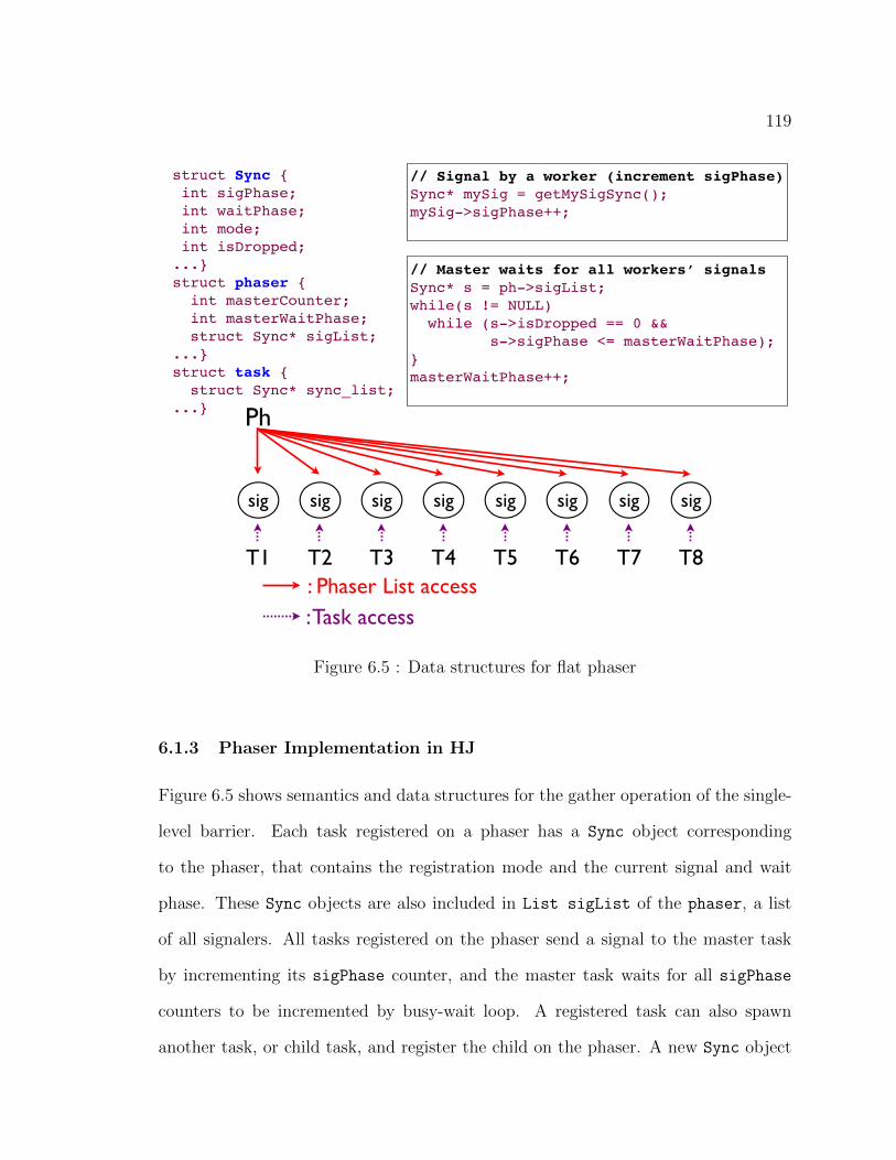
119
struct Sync { int sigPhase; int waitPhase; int mode; int isDropped;...}struct phaser { int masterCounter; int masterWaitPhase; struct Sync* sigList;...}struct task { struct Sync* sync_list;...}
sig
T1
Ph
sig
T2
sig
T3
sig
T4
sig
T5
sig
T6
sig
T7
sig
T8: Phaser List access: Task access
// Signal by a worker (increment sigPhase)Sync* mySig = getMySigSync();mySig->sigPhase++;
// Master waits for all workers’ signalsSync* s = ph->sigList;while(s != NULL) while (s->isDropped == 0 && s->sigPhase <= masterWaitPhase);}masterWaitPhase++;
Figure 6.5 : Data structures for flat phaser
6.1.3 Phaser Implementation in HJ
Figure 6.5 shows semantics and data structures for the gather operation of the single-
level barrier. Each task registered on a phaser has a Sync object corresponding
to the phaser, that contains the registration mode and the current signal and wait
phase. These Sync objects are also included in List sigList of the phaser, a list
of all signalers. All tasks registered on the phaser send a signal to the master task
by incrementing its sigPhase counter, and the master task waits for all sigPhase
counters to be incremented by busy-wait loop. A registered task can also spawn
another task, or child task, and register the child on the phaser. A new Sync object

120
T1
Ph
T2 T3 T4 T5 T6 T7 T8
: List access: Task access
: Tree accessTier 0
Tier 1
Tier 2
struct SubPhaser { Sync* sigList; // Only leaf sub-phaser contains int masterSigPhase; // Signal for the higher tier int masterWaitPhase; // Wait for the lower tier struct SubPhaser* parent; // Parent in the tree...}struct phaser { int masterPhase; // Signal to broadcast...}
Figure 6.6 : Data structures for tree phaser
corresponding to the child task is appended to sigList, and the child task attends
to synchronizations on the phaser. Busy-wait loops in phaser runtime have timeout
periods that can be specified as a runtime parameter. When a busy-wait loop times
out, the task sleeps and the hardware thread switches to another task. Once every
signaler has signaled, the master wakes up all suspended workers serially.
We have seen that the hierarchical phaser employs a tree of sub-masters, instead of
a single master. When an task spawns a child task, the child is registered on the same
leaf sub-phaser as its parent activity until the number of activities on the leaf reaches
numDegree. If the leaf is full, the child activity is registered on another leaf sub-phaser.

121
This process continues so long as the total number of levels does not exceed numTiers.
Since this process needs additional atomic accesses, the initialization (registration)
overhead of hierarchical phasers is generally larger than flat phasers. Figure 6.6
shows semantics and data structures for the gather operation of the tree-based barrier.
Every sub-phaser has two counters that track the current signal phase and wait phase,
named masterSigPhase and masterWaitPhase. SubPhaser contains List sigList,
sigPhase and masterWaitPhase counters. The sigList of a leaf sub-phaser includes
Sig objects for tasks that are assigned to the leaf sub-phaser. phaser class has
a two dimensional SubPhaser array and all tasks can access the hierarchical sub-
phasers so that any eligible task can be a master task to advance the sub-phaser.
In the gather operation, all sub-masters on leaf sub-phasers check their sigList
and wait for the signals from other tasks in parallel, and increment their sigPhase
counters after waiting the signals. A sub-master on non-leaf sub-phaser waits for
the sigPhase increments of its child sub-phasers and also increments its sigPhase.
Finally, the global master receives the signal from the top level sub-phasers and
finishes the hierarchical gather operation. The phaser has a global counter counter
called masterPhase. After the gather operation completes, the broadcast is carried
out to all waiters by incrementing the masterPhase counter.
6.2 Research Contributions
In this work, we present generalized scalable designs for high-performance synchro-
nization with the phaser model. We show applicability for extreme-scale systems
with implementations for multicore and manycore architectures, and across compute
nodes. We also preserve the simple phaser programming model to make applications
portable across a wide range of systems. The contributions of this thesis in the phaser

122
synchronization model can be summarized as:
• A generalized tree-based phaser synchronization algorithm.
• The design and implementation of the multicore phaser synchronization model
for dynamic task parallelism in Habanero-C.
• The design and implementation of the manycore phaser synchronization model
with hardware optimizations for the Cyclops64 manycore processor.
• The design and implementation of a hybrid phaser synchronization model for
unified shared and distributed memory collective synchronization using the HC-
COMM runtime.
• Support for phaser accumulators in both intra-node and hybrid phaser imple-
mentations.
6.3 Phasers for Multicore Synchronization
In this section, we shall look at the phaser design for multicore architectures. This
model integrates phaser into Habanero-C, a dynamic task parallel language. This
language integration is similar to the Habanero-Java model. Next, we look at some
of the details of the phaser data structure in Section 6.3.2. Finally, we describe the
details of a novel algorithm for tree-based phaser synchronization in Section 6.3.3 that
overcomes some of the limitations of the HJ model.
6.3.1 Programming Model for Habanero-C
The phaser synchronization model in Habanero-C follows closely to Habanero-Java
model described in Section 6.1.1. In Habanero-C, tasks can register on a phaser

123
in one of the 3 modes: SIGNAL WAIT MODE, SIGNAL ONLY MODE, and WAIT ONLY MODE.
The phaser mode signifies its capabilities when performing synchronization operations.
The Habanero-C language interface for phasers includes:
• Creation: PHASER CREATE(mode) creates a phaser object and registers the calling
task on the phaser with the specified mode.
• Registration: A child task can register on a phaser object that was cre-
ated by the parent using the phased clause in the async statement. async
phased 〈stmt〉 registers the async with all phasers created by the par-
ent in the immediate enclosing finish scope and asynchronously execute
〈stmt〉. async phased SIGNAL ONLY( ph1, ... ) WAIT ONLY( ph2, ... )
SIGNAL WAIT( ph3, ... ) 〈stmt〉 registers an async on specific phasers with
specific modes. The parent should be registered on all the phasers in modes that
are greater than or equal to the modes of the child as shown in Figure 6.1.
– SIGNAL WAIT > SIGNAL ONLY
– SIGNAL WAIT > WAIT ONLY
– SIGNAL ONLY = WAIT ONLY
• Synchronization: The next statement executed by a task will synchronize the
task on all the phasers that it is registered on.
Figure 6.7 shows an example of using phasers to implement a barrier among
multiple asynchronously created tasks. The async statement in line 4 and the j-for
loop create ntasks child tasks, each registering with the phaser created in line 2 in the
same mode as in the master task. The next statement in line 8 is the actual barrier
wait; each task waits until all tasks arrive at this point in each iteration of the i-for

124
1: finish { 2: new_phaser(SIGNAL_WAIT); 3: for (int j=0; j<ntasks; j++) 4: async phased IN(j) { 5: for (int i=0; i<innerreps; i++) { 6: delay(delaylength); 7: printf("Task %d at step %d!\n", j, i); 8: next; } 9: } }
Figure 6.7 : Barrier Example
loop. The first next operation of each task causes itself to wait for the master task
to do next operation or to deregister. When the master task reaches the end of the
finish scope, it deregisters from the phaser so all child tasks continue and synchronize
by themselves in each iteration.
6.3.2 Phaser Data Structure
The implementation of hierarchical phasers in Habanero-C is a completely new design
that is optimized to take advantage of the runtime’s memory management. In this
phaser model, the constructor for a hierarchical phaser differs from the HJ version
shown in Section 6.1.1 by removing the numTiers parameter. All other the program-
ming constructs remain unchanged between flat phasers and hierarchical phasers.
Figure 6.8 shows the hierarchical phaser design for Habanero-C. There are three
main components to the phaser design: the basic phaser data structure, the tree of
sub-phasers and the phaserSync objects. The subphaser tree is built dynamically at
runtime when tasks register on the phaser in a signaling mode. These tasks form
attach themselves to the leaf nodes of the subphaser tree. Tasks registering with
wait-only mode do not get attached to the tree. During synchronization, signaling
tasks increment their local phase counter to indicate a signal. Tasks registered on

125
PHASER
- phase - root
- leaf
- landing_pad
- unfixed_sph
S2
S5
S3 S1 S6
S4
S0
T0 T1 T2 T3 T4 T5 T6 T7
SW S SW SW S S S SW
T0 T2
T3
T7
T0 T1 T2 T3 T4 T5 T6 T7
S3 S4 S5
SUBPHASER - subphase - submaster - fixedmaster
Figure 6.8 : Generalized Phaser Tree Data Structure (Degree = 2)
the phaser with a wait mode compete to become masters of the subphaser nodes in
the tree. Let us call a master of a subphaser to be a submaster. It is the submas-
ter’s responsibility to gather the signals from the children. For leaf subphaser nodes,
the children are the signaling tasks, while for internal subphaser nodes, the children
would subphaser nodes as well. After a submaster gathers signals from its children,
it increments the phase of the subphaser node, thereby indicating a signal from that
subphaser node to the parent subphaser node. This way the signals from the tree
propagate from the leaves to the root. When the root has gathered signals from its
children, it indicates the completion of all signals in that synchronization phase. Fol-
lowing this, the master at the root will increment the overall phase of the phaser to
indicate the start of the next phase.

126
A major performance overhead is the competition amongst waiters to become
submasters. Competition is resolved through an atomic compare-and-swap (CAS)
operation, which is typically more expensive than non-atomic operations. Considering
n signalers at the leaves of a complete binary subphaser tree with n−1 internal nodes,
imply at least n − 1 CAS operations for every synchronization phase. This can be
considered as large overhead. To reduce this overhead, we can assign a fixed waiter
task for a subphaser node. In case, that task drops out of the phaser, the subphaser
node will become unfixed and will need to be reassigned to another waiter. This
dynamic fixing of the subphaser nodes is handled by our algorithm.
Most of the basic phaser data structure derives from the hierarchical phaser design
for Habanero-Java 6.1.2. Figure 6.8 shows some of the important member fields of
the phaser data structure. There are a few other variables that the runtime main-
tains which we are going to elaborate on them while describing the algorithm in
Section 6.3.3.
phase This counter, as the name suggests, tracks the current phase of this synchro-
nization object.
master This counter helps decide whether the phaser has already selected a master
of this phase. As mentioned before, it is the phaser master’s responsibility to
finally broadcast the phase increment.
leaf This variable always points to the very first subphaser structure that gets created.
It gets set once and never changes after it is set.
root This variable points to the root of the subphaser tree. The root can change
dynamically as the tree grows when more tasks register on the phaser. Currently

127
the implementation does not shrink the overall tree when tasks drop. Instead
whole subtrees of the phaser tree have the option of being deactivated.
landing pad This variable holds a list of signalers who have just registered on the
phaser and have not yet completed one phase transition operation. They are
taken off the list by the root master before broadcasting the phaser transition.
Tasks are added to the list in ascending order of the unique registration identi-
fiers. A task blocks until all lower identifiers are have been added to the list.
unfixed sph This variable holds a list of subphaser objects that do not have a fixed
master assigned.
Hierarchical phasers consists of a tree of subphasers inside the main phaser data
structure. The subphaser tree node’s degree is set as a parameter when the phaser is
created. The leaf nodes of the tree contain degree number of tasks while the internal
nodes contain degree number of subphasers. In Figure 6.8, the subphaser structures
are in the circles denoted by Si. Some of the important components of the subphaser
are:
subphase This is for the subphaser to gather signals from the children and propagate
a signal to the parent.
submaster This variable helps to decide the master who gathers the signals of its
children in case the master has not been fixed.
fixedwaiter This variable points to the active task which is fixed to be master of
the subphaser for every synchronization phase.
The phaserSync objects act as an interface between the task and the phaser object.
When a task registers on a phaser, it creates the appropriate phaserSync objects

128
according to the mode of registration. In Figure 6.8, the phaserSync objects are in the
rectangles denoted by Tk. For all signal modes such as signal-only or signal-wait,
a sigSync object is created, while for all wait modes, a waitSync is created. Both
sigSync and waitSync objects are maintained by the task. References to registered
sigSync objects are also maintained by the subphaser tree leaves. Every sigSync object
maintains a phase variable to notify the phaser master that the signal has been done.
Every waitSync object also maintains a phase variable which helps in busy waiting
on the phaser broadcast. The sigSync maintains a isActive boolean field to notify the
phaser master in case it has dropped off. If a task is a fixed master on a subphaser,
then the waitSync object maintains a reference to that subphaser with the fixed sub
phaser variable.
6.3.3 A Generalized Tree-based Phaser Synchronization Algorithm
Past work on hierarchical phaser synchronization [112] suffers from two limitations.
Firstly, there is no support for tasks with signal-only registration modes. With such
a restriction, it is not possible to express point-to-point synchronization patterns.
Secondly, the phaser tree size is fixed at the time of phaser creation. The user has
to specify the maximum allowed height (T ) and degree (D) of the tree as part of
constructor. This implies that the user should have prior knowledge of the maximum
number of tasks (DT ) that can register on a phaser, which is a restriction for dynamic
task parallel computation on extreme-scale systems. In this section, we describe a
new generalized tree-based phaser synchronization algorithm aiming to overcome these
limitations.
The phaser synchronization model can be broadly classified into three distinct
parts during the lifetime of a task associated with a phaser object. First, the reg-

129
istration process associates the task and the phaser object. Following registration
a task begins the active synchronization operations. Finally, the de-registration or
drop step disassociates the task from any further participation in the phaser object’s
activities.
Registration Phase
There are two phaser registration scenarios. First, when a task creates a phaser, that
task is automatically registered on the phaser as part of the phaser creation function.
Second, when a task creates a child task, the parent has the option of registering
the child on the phaser objects that the parent is registered on and shares the same
immediately enclosing finish scope. In either case, the registration process associates
the phaser object with the phaserSync objects depending on the registration mode. A
phaserSync object, as described in Section 6.3.2, acts as the interface between a task
and the phaser object.
Algorithm 2: PhaserRegistration
Data: phaser ph, mode m
Result: sync objects s and w
if m 6= signal only then
w ←− initializeWaitSync();
end
if m 6= wait only then
s←− initializeSigSync();
InsertSigIntoPhaserTree(ph, s);
end

130
Algorithm 2 shows the pseudocode for the registration function. If the registra-
tion mode has a wait component, then a waitSync object is created and initialized.
Similarly, if the registration mode has a signal component, then a sigSync object is
created and initialized. The function returns these objects to the caller where they
would added to the frame of the task being registered. If a sigSync is created, this
object is added to the phaser tree, which consists of a tree of subphaser nodes where
the leaf subphasers have sigSync objects attached.
Algorithm 3 shows the function pseudocode for adding a sigSync to the phaser
tree. The function first assigns a unique identifier to the new task, using an atomic
increment of a shared counter, sigCounter. This id tells us the insertion position at
the leaf level, the leaf subphaser number and the offset into that subphaser based on
the degree of the tree. If the offset is 0, then the task is responsible for setting the
phaser tree appropriately. But for a non-zero offset, the insertion busy waits until the
subphaser shows up on the tree. The task which gets the responsibility of setting up
the subphaser, also busy waits until all the previous leaves have been setup. However,
the tree setup function can be concurrent with non-zero offset insertions in previous
leaves. The task starts setting up the tree by creating the leaf subphaser and adding
more sub-phasers to the tree if required in order to complete the tree. Once the tree
has been setup, the leafCounter variable is incremented so that other tasks waiting
on this leaf subphaser can proceed.
The tree insertion routine also performs two other functions. First, if this task
has a wait component, then, it may be a good choice to become a fixed master
on a subphaser in the tree. Fixed masters have the advantage of not employing an
atomic operation to become a master dynamically during a synchronization operation.
However, we allow only tasks registered in signal-wait mode to become fixed masters

131
Algorithm 3: InsertSigIntoPhaserTree
Input: phaser ph, sig sync s
sigId←− getUniqueSigId(ph.sigCounter);
sphId←− sigId/ph.degree; /* leaf sub-phaser */
sphOff ←− sigId%ph.degree; /* offset into leaf sub-phaser */
if sphOff = 0 then
sph←− subPhaserCreate();
if sphId = 0 then
ph.leaf ←− sph;
else
busy wait until ph.leafCounter reaches sphId;
append sph to the list of leaves and setup the rest of the tree;
end
sph.sigArray[0]←− s;
atomic increment of ph.leafCounter
else
busy wait until ph.leafCounter reaches sphId + 1;
traverse list of leaves to reach leaf with id sphId;
sph.sigArray[sphOff ]←− s;
end
s.leaf ←− sph;
if isSigWait(s) then
if FixSubPhaser(s) = false then
AddSubPhaserToUnfixedList(sph);
end
end
InsertToLandingPad(ph, s);

132
Algorithm 4: FixSubPhaser
Input: sig sync s
Output: True if a subphaser master gets fixed. False otherwise.
sph←− s.leaf ;
while sph do
if trySynchronizedMasterF ix(sph, s) = true then
s.wait.fixedsph←− sph;
return true
end
sph←− sph.parent;
end
return false
so that the synchronization phase does not suffer from any delays resulting from
wait-only tasks. Algorithm 4 shows the pseudocode for this function. The current
algorithm fixes a task as master on a subphaser on the path from the leaf to root
only to benefit from locality of the gather operation. If the task that is performing a
gather operation shares a level of cache with one who needs to signal, then the busy
wait basically spins on a cache line getting dirty without going through the system
bus. If such a scenario comes about at runtime, it will boost performance and greatly
reduces unnecessary memory traffic. We do not try to reshape or rebalance the tree
with respect to fixed masters. Fixed masters will depend on dynamic registration
order of signal-wait tasks. In the worst case, a fixed master may inhibit another
signal-wait task in its subtree from becoming a fixed master, and may end up
gathering signals from a sibling subtree as well. The second function of the registration

133
phase adds the sigSync object to a list on the phaser known as the landing pad. The
landing pad ensures that there are no racy registrations when the tree root master
gathers all signals. A common racy scenario is when one task is waiting at the root of
the tree while another task is creating a child whose registration would add an extra
level to the tree. As soon as the registration is done, and the parent signals on the
tree, the task at the root being unaware of the new registration would erroneously
conclude that all tasks have signaled. In fact, the root itself has now changed from
before. The landing pad along with a dynamic root check ensures that this situation
is averted. This is one of the critical design features for supporting all modes of
registration on the phaser tree.
Synchronization Phase
This part of the algorithm deals with the phaser synchronization operation called
next. The next operation comprises of the signal and wait functions. If a task’s
registration mode is signal-only, then a next perform only the signal. Similarly
when the task is in wait-only mode, the next does only the wait. In all other modes,
both signal and wait are performed.
Algorithm 5 shows the pseudocode for the signal operation. In order to signal,
the task increments the phase counter on the sigSync object. The checkphase counter
keeps track of early signal operations done by the task. If the checkphase lags behind
the phase, then a signal done through a next become a no-op. Additionally this
function checks if there is any requirement for a traversal of the tree to fix this
task as the master of an unfixed subphaser. The check is done with one compare
operation and so it does not add much overhead for a regular next when the check
fails. However, when the condition succeeds, then the task has to check if it can

134
Algorithm 5: PhaserSignal
Input: sig sync s
if s.phase = s.checkphase then
if checkUnfixedSubPhasers() = true then
FixSubPhaser(s);
end
s.phase + +;
end
s.checkphase + +;
become the master of an unfixed subphaser. This requirement of this dynamic fixing
may arise when a task that was previously a fixed master on a subphaser drops from
the phaser, and in the process unfixes the subphaser.
Algorithm 6 shows the wait operation. In this function, the task first checks if it
is the fixed master of a subphaser, and if that fact is true, then it proceeds to perform
a wait operation on that subphaser. This wait operation is shown by the function
doWaitTree in Algorithm 7. But, if the task is not a fixed master of any subphaser,
it tries to become the phaser master. The phaser master has the responsibility of
ensuring all the tree signals have arrived before broadcasting the phase change to all
waiters. This functionality is shown in the doWaitPhaser function in Algorithm 9
and is explained later.
The doWaitTree function ensures that the master of a subphaser waits for all
signals in it’s subtree followed by waiting for the parent subphaser’s phase change.
The master first checks if the subphaser is a leaf, and if so, it gathers the signals from
the sigSync objects attached to the leaf subphaser. If the subphaser is not a leaf, then

135
Algorithm 6: PhaserWait
Input: phaser ph, wait sync w
if w.fixedsph 6= ∅ then
doWaitTree(w,w.fixedsph, true);
end
while w.phase ≥ ph.phase do
if ph.master = 0 then
if ph.fixedmaster = w then
doWaitPhaser(ph, w);
else
busy wait for either ph.phase or ph.master to change;
end
else
if isPhaserUnfixedMaster(ph, w) = true then
doWaitPhaser(ph, w);
else
busy wait for either ph.phase to change;
end
end
end

136
Algorithm 7: doWaitTree
Input: wait sync w, subphaser sph, boolean checkparent
if isLeaf(sph) then
busy wait on array of signaler tasks;
else
foreach child subphaser c do doWaitNode(w, c, false);
end
sph.phase + +;
if sph.parent 6= ∅ & checkparent = true then
doWaitNode(w, sph.parent, true);
end
Algorithm 8: doWaitNode
Input: wait sync w, subphaser sph, boolean checkparent
while wait.phase ≥ sph.phase do
if sph.fixedwaiter 6= ∅ then
busy wait for sph.phase to change or sph.fixedwaiter be inactive;
else
if isSubPhaserUnfixedMaster(sph, w) = true then
doWaitTree(w, sph, checkparent);
else
busy wait for either sph.phase to change;
end
end
end

137
Algorithm 9: doWaitPhaser
Input: phaser ph, wait sync w
foreach element s in ph.landingpad do busy wait until s.phase > ph.phase;
r ←− ∅;
while r 6= ph.root do
r ←− ph.root;
doWaitNode(w, ph.root, 0);
end
Remove sub phasers with fixed masters from unfixed list;
ph.phase + +;
it gathers signals from children subphasers by calling the function doWaitNode shown
in Algorithm 8. Once all the signals have arrived from the children, the subphaser’s
phase change is signaled by incrementing the subphase variable.
The doWaitNode function checks if the subphaser already a fixed master, and if
so, then waits for the fixed master to signal the phase change on that subphaser.
If the function detects that the fixed master has dropped, or if there was no fixed
master in the first place, then it tries to become a temporary master by performing
an atomic compare- and- swap on the submaster variable. On succeeding it performs
a doWaitTree function on that subphaser. On failure, it waits for the subphaser to
signal a phase change.
Now, the doWaitTree function takes a boolean argument called checkparent. If the
argument is true, then it means that the function cannot complete until the parent has
signaled a phase change. The rationale is that even if a fixed master of a subphaser has
signaled it phase change, the only way to ensure progress is to ensure that your parent

138
has gathered all signals in its subtree. So, the fixed master calls a doWaitNode on the
parent. Consider the scenario when there is only one task registered in signal-wait
mode on the phaser and all others are in signal-only mode. Since, only tasks with
signal-wait can become fixed masters, this task would basically have to gather the
signals from all others. This ensured by the algorithm through checking the parent
after collecting signals from its subtree.
The doWaitPhaser function is called by the task which is the global master of
this phaser. The global master may also have a task fixed as its master in order to
reduce the atomics required to be temporary master. This function first waits for all
signals from the landing pad list of tasks. Once the signals have arrived, the tasks are
removed from the landing pad. Next, the global master performs a doWaitNode on
the root of the phaser tree. Doing this ensures that the global master has collected
all the signals in the subtree under the root. Consider the scenario when all the tasks
registered on the phaser tree are in signal-only mode. In such a case, the global
master will ensure that it gathers all their signals through the doWaitNode function.
Now, it might be the case during the gather of signals though the root, more tasks
get registered on the phaser and the tree grows new levels. This would imply that the
root has changed from the time the global master started the doWaitNode function.
As a result, the algorithm checks for this change and repeats the process if there
was indeed a change to the root. After gathering all signals from a stabilized root,
the global master removes all subphasers from the unfixed sph list which have found
new fixed masters. The final step of this function broadcasts the phase change in the
phaser by incrementing the phase variable.

139
Algorithm 10: PhaserDropSig
Input: phaser ph, sig sync s
if s.wait 6= ∅ then
if s.wait.fixedsph 6= ∅ then
s.wait.fixedsph.fixedmaster ←− ∅;
Add s.wait.fixedsph to ph.unfixedsubphasers list;
end
if ph.fixedmaster = s.wait then
ph.fixedmaster ←− ∅;
end
end
s.isActive←− 0
De-registration Phase
The de-registration phase is to drop a task from the phaser. As mentioned earlier in
the HJ phaser model, tasks are dropped either on completion or on an explicit drop
call. The task simply has to make its sigSync object inactive. Additionally, if the
task was a fixed master on a subphaser then it has to make that subphaser available
for other tasks to become the fixed master. This is done by clearing the fixedmaster
variable on the subphaser and also adding the subphaser to the unfixed sph list.
In this section, we have seen that the algorithm can handle all kinds of registration
modes on a phaser tree and improves performance by managing fixed masters for the
subphaser tree. Furthermore, the synchronization algorithm also takes advantage of
locality benefits in a fully dynamic task parallel environment. The salient points of
this algorithm can be summarized as follows.

140
• Supports task registration for all the modes.
• Supports an unlimited number of tasks participating in the tree synchronization.
• Dynamic management of fixed masters in the phaser tree thereby greatly re-
ducing system bus contention.
• Locality aware fixed master assignment for improving busy-wait performance.
6.3.4 Results
In our multicore experiments, we compare phaser performance for barrier synchro-
nization against OpenMP barrier implementations on various platforms. The barrier
microbenchmark was based on the EPCC OpenMP syncbench test that was developed
for evaluating OpenMP barrier overhead [113]. The benchmark runs a loop with a
barrier call in its body. This loop is run for a very large number of iterations. The
total running time of the loop is divided by number of iterations to get the average
time per iteration. Similar to this method, a reference loop is also run which does
not contain the barrier call in its body. The average iteration time of the reference
loop is then subtracted from the original loop iteration time to produce the barrier
overhead time. This constitutes one sample. After many such samples are collected,
the minimum, maximum and average times are obtained and displayed along with
the standard deviation. In these results, we present the minimum of all the barrier
overhead samples. For OpenMP barrier times, we collected results with OMP WAIT
POLICY set to ACTIVE as well as the default configuration. We report the best times
achieved from either configuration.
Figure 6.9 compares barrier performance of Phaser against OpenMP implemen-
tation by the Intel icc and GCC compilers. The execution platform was an Intel

141
2 4 6 8 12
Phaser 0.25 0.30 0.32 0.66 0.83 icc OpenMP 0.21 0.29 0.39 0.65 0.90 gcc OpenMP 0.16 0.26 0.44 0.93 1.23
0.00
0.20
0.40
0.60
0.80
1.00
1.20
1.40
Time (us)
Processors
Intra-‐Node Barrier Synchroniza:on
Phaser icc OpenMP gcc OpenMP
Figure 6.9 : Barrier Synchronization on x86 node
Westmere node with 12 processor cores running at 2.83 GHz. We used Intel icc
compiler version 12.0.4 and GCC compiler version 4.4.6 and for each case we bound
the threads to cores at runtime. The Intel OpenMP implementation by default used
the hyper algorithm for the barrier operation, a hypercube-embedded tree gather and
release algorithm. Two other barrier implementations, namely the linear and tree al-
gorithms, were also tested by setting the environment variable KMP PLAIN BARRIER
PATTERN, and the best times are reported. The GCC OpenMP implementation used
a counting barrier implementation. The results show that phaser outperforms both
icc and GCC as we scale up to 12 cores.
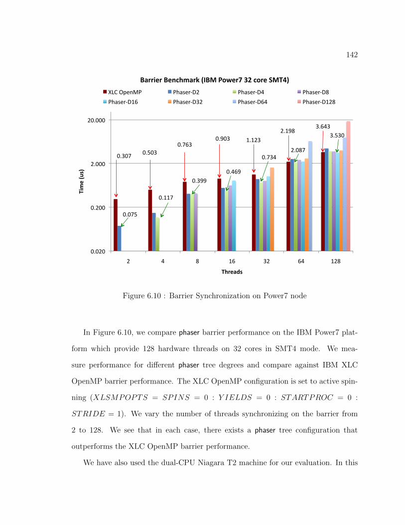
142
0.307 0.503 0.763
0.903 1.123
2.198 3.643
0.075
0.117
0.399 0.469
0.734 2.087
3.530
0.020
0.200
2.000
20.000
2 4 8 16 32 64 128
Time (us)
Threads
Barrier Benchmark (IBM Power7 32 core SMT4)
XLC OpenMP Phaser-‐D2 Phaser-‐D4 Phaser-‐D8
Phaser-‐D16 Phaser-‐D32 Phaser-‐D64 Phaser-‐D128
Figure 6.10 : Barrier Synchronization on Power7 node
In Figure 6.10, we compare phaser barrier performance on the IBM Power7 plat-
form which provide 128 hardware threads on 32 cores in SMT4 mode. We mea-
sure performance for different phaser tree degrees and compare against IBM XLC
OpenMP barrier performance. The XLC OpenMP configuration is set to active spin-
ning (XLSMPOPTS = SPINS = 0 : Y IELDS = 0 : STARTPROC = 0 :
STRIDE = 1). We vary the number of threads synchronizing on the barrier from
2 to 128. We see that in each case, there exists a phaser tree configuration that
outperforms the XLC OpenMP barrier performance.
We have also used the dual-CPU Niagara T2 machine for our evaluation. In this

143
2 4 8 16 32 64 128
HC So,ware Barrier-‐Tree 0.95 1.17 1.43 1.67 2.42 3.48 9.38 HJ So,ware Barrier-‐Tree 2.1 2.5 3.2 4.1 5.3 7.2 13.6 HC So,ware Barrier-‐Flat 0.85 1.16 1.86 2.21 4.31 7.87 32.17 HJ So,ware Barrier-‐Flat 1.6 2.5 3.4 5.1 8.4 16.8 53.5 OpenMP 0.6 0.73 0.86 1.22 2.78 9.98 10.58
0 4 8
12 16 20
Overhead (us)
# threads
Barrier Overhead on Dual CPU Niagra T2
Figure 6.11 : Phaser barrier overhead on a dual-CPU Niagara T2 machine
machine, each Niagara T2 CPU has 8 hardware cores, each of which can sustain 8
SMT (simultaneous multithreading) threads for a total of 128 concurrent threads.
The experiments run on the Solaris 10 operating system and they were compiled us-
ing the Sun Studio 10 (update 1) OpenMP compiler. Figure 6.11 presents the barrier
overhead of our phaser implementation and OpenMP on the 128-thread Niagara T2
machine. For comparison, we also include the results of Habanero-Java phaser imple-
mentation. Due to the lack of hardware support for barriers or thread suspend/awake
in the Niagara T2 processor, we only evaluate the barrier implementation using the
busy-wait approach with and without hierarchical phasers. We can see that hierarchi-
cal phasers reduce the barrier overhead by a large margin for both the Habanero-C and
Habanero-Java, while the Habanero-C tree implementation outperforms the OpenMP
barrier.

144
(a) Cyclops64 Node
LatencyOverall Bandwidth
Load: 2 cycles; Store: 1 cycle
640GB/s
Load: 57 cycles; Store: 28 cycles16GB/s (Multiple load and Multiple store
instructions); 2GB/s
Load: 31 cycles; Store: 15 cycles
320GB/s
64Registers
SP16kB
GM~2.5MB
Off-ChipDRAM
1GB
Read: 1 cycleWrite: 1 cycle
1.92 TB/s
(b) Cyclops64 Memory
Figure 6.12 : Cyclops64 Architecture Details
6.4 Phasers for Manycore Synchronization
In this Section, we explore a phaser implementation that leverages hardware support
for synchronization using the IBM Cyclops64 (C64) manycore chip [114] as our eval-
uation platform. The IBM Cyclops64 is a massively parallel manycore architecture
initially developed by IBM as part of the Blue Gene project. As shown in Figure 6.12,
a C64 processor features 80 processing cores on a chip, with two hardware thread units
per core that share one 64-bit floating point unit. Each core can issue one double
precision floating point Multiply Add instruction per cycle, for a peak performance
of 80 GFLOPS per chip when running at 500MHz. The processor chip includes a
high-bandwidth on-chip crossbar network with a total bandwidth of 384 GB/s. C64
employs three-levels of software-managed memory hierarchy, with the Scratch-Pad
(SP) currently used to hold thread-specific data. Each hardware thread unit has a
high-speed on-chip SRAM of 32KB that can be used as a cache.
C64 utilizes a dedicated signal bus (SIGB) that allows thread synchronization
without any memory bus interference. The SIGB connecting all threads on a chip

145
Name Description
tnt create(...) Create a TNT thread; its syntax is similar to pthread create
tnt join(...) Wait for a thread to terminate, similar to pthread join
tnt suspend() Suspend current thread
tnt awake (const tnt desc t) Awaken a suspended thread
tnt barrier include (tnt barrier t *) Join in the next barrier wait operation
tnt barrier exclude (tnt barrier t *) Withdraw from the next barrier wait operation
tnt barrier wait (tnt barrier t *) Wait until all threads arrive this point
Table 6.2 : Cyclops64 TNT APIs for Hardware Synchronization Primitives
can be used for broadcast operations taking less than 10 clock cycles, enabling effi-
cient barrier operations and mutual exclusion synchronization. Fast point-to-point
signal/wait operations are directly supported by hardware interrupts, with costs on
the order of tens of cycles. The C64 tool chain includes a highly efficient threading
library, named TiNy-Threads (TNT) [114], which uses the C64 hardware support
to implement threading primitives. The TNT API is similar to the Pthread API,
simplifying porting of pthread-based runtime systems and applications to Cyclops64.
Additionally, TNT provides APIs that can be used to access the hardware synchro-
nization primitives to allow for suspension of threads, and including and excluding
specific threads from barriers, as shown in Table 6.2.
6.4.1 Optimization Using Hardware Barriers
Phasers can be optimized in manycore architectures that offer direct hardware support
for barriers, such as C64. The phaser runtime is able to detect if a phaser operation
specified by the user program is equivalent to a barrier operation by checking whether

146
all phasers are registered in signal-wait mode. If so, the underlying hardware
support is used directly to perform the barrier operation. Detecting whether or not
a particular operation is equivalent to a barrier is straightforward from the phaser
model; hardware barriers can be used when all tasks on a phaser are registered in
signal-wait mode.
Implementing a hardware barrier in a phaser requires threads to include them-
selves in the barrier by calling tnt barrier include. This requirement is particularly
interesting in a tasking environment due to the fact that the worker thread that exe-
cutes the task has to include itself in the hardware barrier. The Habanero-C runtime
only includes a worker in the hardware barrier when it is ready to execute a task.
The C64 chip supports five hardware barriers that can be accessed using the TNT
barrier API. If a programmer uses more than five barriers in a program, the extra
barriers will execute as software barriers.
6.4.2 Optimization Using Thread Suspend and Awake
The TNT API provides functions to suspend a thread and to awake a sleeping thread.
A suspend instruction temporarily stops execution in a non-preemptive way, and a
signal instruction awakes the sleeping task. Using thread suspend and awake mecha-
nism in place of the busy-wait approach reduces memory bandwidth pressure because
all waiting tasks can suspend themselves instead of spinning. The master can collect
all the signals from waiting tasks and finally signals the suspended tasks to resume
the execution.
The C64 chip provides an interesting hardware feature called the “wake-up bit”.
When a thread tries to wake up another thread, it sets the “wake-up bit” for that
thread. This enables a thread to store a wake-up signal. Hence, if a thread tries to

147
suspend itself after a wake-up signal is sent, it wakes up immediately and the suspend
effectively becomes a no-op. This feature is utilized by phasers to transition from one
phase to the next without worrying about a thread that can execute a suspend after
a wake up signal.
6.4.3 Adaptive Phasers
Adaptability is one of the main features of our phaser implementation. As explained
before, the runtime can directly detect the synchronization operation being performed
and make a reasonable decision as to how to execute it. A phaser operation can
switch to the optimized versions that utilize hardware primitives. These details of
how a phaser operation is executed are hidden from the user.
Phaser operations can be implemented in a number of ways to take advantage
of the particular characteristics of the underlying hardware. Even when a phaser
has all tasks registered in signal-wait mode, it is not guaranteed that a hardware
barrier will be used. A task that is registered to support split-phase or fuzzy barriers
may signal ahead of its next operation. When a task registers as signal-only or
wait-only on a phaser that has been using a hardware barrier, our runtime detects
such a scenario and switches to software mode. The runtime chooses the best mode
of operation, depending on the current program state and available features. Each
implementation alternately exhibits particular traits: maximum portability and rea-
sonable performance is achieved with a busy-wait implementation; low bandwidth
and low power usage are featured in the suspend-awake implementation.

148
6.4.4 Memory Optimizations
Phaser and phaserSync objects contain volatile phase counters, and phaser operations
involve frequent read and write of those counters in both software based busy-wait ap-
proach and hardware-optimized implementations. So low latency and high bandwidth
of the memory system are key to the performance of phasers. The C64’s memory hi-
erarchy, as seen in Figure 6.12, is similar to hardware cache in regular commodity
CPUs. The power of using it comes from program manageability as our runtime itself
can decide which synchronization objects need to reside on or move to the high-speed
SRAM. Yet there is a tradeoff in this software-managed caching approach because
the DRAM is limited in its sizes and shared with stack in C64. For a simple DRAM-
optimization, the runtime allocates on SRAM, synchronization objects that contain
spinning counters. More complex optimizations use heuristic or historical informa-
tion to identify frequently-accessed data and move them to SRAM. Further memory
management by the Habanero-C runtime, such as allocating a list of synchronization
objects in a dense array, provide another level of memory optimizations on C64.
6.4.5 Results
Results of Memory Optimization on Cyclops64
In Figure 6.13, we show the barrier overhead of using software phasers that reside
on either SRAM or DRAM. By allocating the synchronization objects in SRAM, we
avoid spinning on flags allocated on the DRAM. Similar to past results [17] that
show the benefits of local spinning and avoiding spinning across the network, we
achieve better performance by spinning on SRAM allocated flags. This optimization
results in dramatic overhead reduction for both flat-phaser and hierarchical-phaser

149
Figure 6.13 : SRAM optimization for phasers on Cyclops64
implementations; two orders of magnitude for flat-phaser and 1 order of magnitude
for hierarchical phaser. From now on, we use SRAM hierarchical phaser implemen-
tation to represent our software phaser when comparing with other hardware-based
implementations.
Results of Barrier and Point-to-Point Microbenchmarks on Cyclops64
The barrier microbenchmark was based on the EPCC OpenMP syncbench benchmark.
Figure 6.14a shows the barrier overheads using four phaser implementations on C64.
The implementation that leverages the C64 hardware barrier incurs much lower over-
head than that of the software barrier. The implementation that uses suspend/awake
performs worse than software phasers because of the sequentially accumulated cost
of hardware interrupt in suspend/awake implementation. For software hierarchical
phasers, both signal gathering and wait operations are performed in parallel, thus

150
0
5
10
15
20
25
30
35
2 4 8 16 32 64 128
Ov
erh
ea
d (
us
)
# threads
phaser with hardware barrier
software barrier-tree
phaser with hardware suspend/awake
software barrier-flat
(a) Phaser Barrier
0
50
100
150
200
250
300
350
400
450
500
2 4 8 16 32 64 128
Tim
e (
us
)
# threads
software phaser
phaser with hardware suspend/awake
(b) Threadring
Figure 6.14 : Barrier and Point-to-Point Microbenchmarks
reducing overhead.
The threadring microbenchmark evaluates point-to-point signal-wait operation of
two tasks. In this program, a group of tasks form a signal ring; each task waits on the
signal from the previous task and signals the next task after receiving the signal. As
shown in Figure 6.14b, the memory consumption of the software busy-wait approach
has little impact on the time required to complete a round of the ring. In fact, the
implementation using software phasers performs slightly better than the one using
hardware interrupts. These imply the effectiveness of using the portable software-
based solution for point-to-point synchronizations. The high performance obtained
using the busy-wait implementation is due in part to the high bandwidth and low
latency of the local on-chip memory in C64. Although the other techniques in our
experiments use hardware support, they still suffer from overhead in the supporting
software required to use the hardware primitives. In contrast, busy-wait uses a very
simple polling mechanism that does not require complex software support.

151
6.5 Phasers for Hybrid Synchronization
Phasers have been extended to support collective operations at inter-node level. We
use the HCMPI programming model to create a hybrid synchronization construct,
called hcmpi-phaser, which uses phaser synchronization at intra-node level and MPI
collective synchronization at inter-node level. In this model, the synchronization
statement next provides unified synchronization for tasks registered on a phaser across
the whole system by using the HC-COMM runtime. In this section, we discuss the
HCMPI phaser barrier and accumulator models. We believe task based unified col-
lective synchronization operations on distributed systems to be a novel contribution.
Phaser API Description
ph = HCMPI PHASER CREATE(int mode) hcmpi-phaser create
ph = HCMPI ACCUM CREATE(int mode,
init val, HCMPI Type type, HCMPI Op oper) hcmpi-accum create
next phaser synchronization
accum next(value) accumulator synchronization
accum get(ph) accumulator result
Table 6.3 : HCMPI PHASER API
The goal of this hybrid synchronization model is to provide clean semantics for
system wide collective operations. We combine inter-node MPI collectives with intra-
node phaser synchronization. An instance of hcmpi-phaser is created using the
HCMPI PHASER CREATE API shown in Table 6.3. Since this hybrid model supports only
MPI collectives at inter-node level, an hcmpi-phaser can only be created using the
signal-wait mode. This also implies that the task which creates the hcmpi-phaser

152
instance is registered in signal-wait mode. Dynamic registration and deregistra-
tion is allowed, as well as arbitrary mode patterns for new tasks created after the
hcmpi-phaser instance. New tasks can be registered on a hcmpi-phaser in one of
signal-wait, signal-only or wait-only modes. So, regardless of the registration
modes used for tasks within a node, the inter-node synchronization will always be a
MPI collective, such as a barrier or a reduction. In a system-wide barrier or reduc-
tion operation, all tasks registered on a hcmpi-phaser have to be in signal-wait
mode. Registered tasks can synchronize both within the node and across nodes us-
ing the synchronization primitive next. The inter-node SPMD model requires that
every rank process creates its own hcmpi-phaser before participating in the system
wide next operation. Figure 6.15 shows an example of using the hcmpi-phaser as a
barrier.
finish {
phaser *ph;
ph = HCMPI PHASER CREATE(SIGNAL WAIT MODE);
for (i = 0; i < n; ++i) {
async phased(ph) IN(i) {
· · · ; next;
· · · //do post-barrier work
} /*async*/ } /*for*/ } /*finish*/
Figure 6.15 : HCMPI Phaser Barrier Model
The HCMPI model integrates intra-node phaser accumulators [115] with inter-
node MPI reducers using the hcmpi-accum construct. An instance of hcmpi-accum
is created using the HCMPI ACCUM CREATE API, shown in Table 6.3. The API takes a

153
HCMPI MAX HCMPI MIN HCMPI SUM
HCMPI PROD HCMPI LAND HCMPI BAND
HCMPI LOR HCMPI BOR HCMPI LXOR
HCMPI BXOR HCMPI MAXLOC HCMPI MINLOC
Table 6.4 : HCMPI Ops
registration mode, an initial value for the reduction element, a type of the element and
the type of the reduction operation. The registration mode can only be signal-wait
in the current implementation. Supported reduction operators are shown in Table 6.4.
In this model, computation tasks at the intra-node level register on a hcmpi-accum
instance and participate in the specified global reduction operation via the runtime
call accum next(value), which takes as an argument the individual datum provided
by the task for the reduction. Tasks arrive at the synchronization point with a
value and participate in all hcmpi-accum instances they are registered with. After
synchronization completes, accum get will return the globally reduced value. At the
inter-node level, we currently only support the MPI Allreduce model. This means
that a call to accum get() will return the globally reduced value. Figure 6.16 shows
an example of the hcmpi-accum model for the SUM operation.
6.5.1 Implementation
HCMPI builds on Habanero-C’s tree-based implementation of phaser and the HC-
COMM runtime to integrate inter-node MPI collectives and intra-node phaser syn-
chronization. Tree based phasers have been shown to scale much better than flat
phasers [112, 116]. HCMPI PHASER CREATE creates a phaser barrier, while HCMPI

154
finish {
phaser *ph;
ph = HCMPI ACCUM CREATE(HCMPI SUM,HCMPI INT);
for (i = 0; i < n; ++i) {
async phased IN(· · · ) {
int* my val = get my val();
accum next(my val);
· · · ;} /*async*/ } /*for*/ } /*finish*/
int* result = (int*)accum get(ph);
Figure 6.16 : HCMPI Phaser Accumulator Model
ACCUM CREATE creates an accumulator object. Tasks can dynamically register to and
drop from a hcmpi-phaser. The next statement and the accum next APIs act as the
global synchronization points for barriers and accumulators. Figure 6.17 illustrates
the synchronization process for HCMPI phaser barrier and accumulator operations.
In the case of a barrier, tasks, T0 to T7, arrive at the next statement and signal
the phaser. Then they start the wait phase. These tasks traverse the internal nodes
of the phaser tree to see if they can become sub-masters at any of the sub-phaser
nodes S0 to S6. The first task to arrive at a sub-phaser becomes the sub-master for
that node. The sub-master collects the signals from its sub-tree and then signals its
parent. This way, signals on the phaser tree propagate up to the root node. The first
task to arrive at the root node becomes the phaser master. Others wait for the phaser
master to signal the start of the next phase. The MPI Barrier operation is started
only after the phaser master at the root sub-phaser receives all signals in the phaser
tree. The phaser master waits on a notification from the communication task that

155
T0 T1 T2 T3 T7 T6 T5 T4
T0 T1 T2 T3 T7 T6 T5 T4
S3 S4 S5 S6
S1 S2
S0
COMM Accum Start (Value)
Done (Value)
COMM PHASER/ ACCUM TASK
MPI
Barrier/ Reduce, etc.
Intra Node
Inter Node
COMM Barrier Start
Figure 6.17 : HCMPI Phaser Barrier
the MPI Barrier operation is completed. Once the notification arrives, the phaser
master signals all the intra-node tasks to start their next phase. In case of phaser
accumulators, each task arrives at the accum next synchronization point with a value
in addition to the signal. The value gets reduced to a single element at the root of
the phaser tree and then the phaser master signals the hcmpi phaser communication
task to start the MPI Allreduce operation. The globally reduced value is saved in
the phaser data structure and can be retrieved by the accum get call on that phaser
object.
6.5.2 Results
We measure the performance of HCMPI phaser barriers and accumulators. We com-
pare against MPI-only and hybrid MPI+OpenMP performance. We used a modified

156
version of the EPCC Syncbench [113] for barrier and reduction (accumulator) tests.
The benchmarks run a loop containing a barrier or reduction operation for a large
number of times. The cost of synchronization is estimated by subtracting the loop
overhead from the iterations. We measure synchronization performance on 2 to 64
nodes while using 2 to 8 cores per node. In our experiment, the MPI-only version
uses MPI THREAD SINGLE, while the hybrid MPI+OpenMP version uses MPI THREAD
MULTIPLE. Both the HCMPI and hybrid versions use one process per node and use
threads for the number of cores used inside a node. The MPI-only version uses one
process for every core used in the experiment to perform distributed collective oper-
ations. The HCMPI test creates the number of tasks and computation workers equal
to the number of cores used per node in the experiment. Together they perform the
integrated synchronization at the intra-node and inter-node level for both barriers and
accumulators. We measure HCMPI phaser barrier performance. The MPI+OpenMP
hybrid version creates a parallel region of number of threads equal to the number of
cores. Threads first synchronize using a OpenMP barrier, then the MPI Barrier is
called by a single thread while the others wait at subsequent OpenMP barrier. The
hybrid reduction test completes a global reduction by first performing an OpenMP for
loop reduction over the number of threads followed by MPI Allreduce by a single
thread. Remaining threads wait at a OpenMP barrier.
The results in Table 6.5 clearly demonstrate that MPI and hybrid times increase
at a faster rate compared to HCMPI with increasing number of cores per node, for
both barriers and accumulators. HCMPI depends on MPI performance for inter-node
synchronization. When scaling up the number of cores within a node, HCMPI is able
to use intra-node phaser synchronization, while MPI depends on MPI Barrier and
MPI Allreduce over all cores. Overall, hybrid MPI+OpenMP outperforms MPI while

157
Collective Synchronization Times in micro-seconds
Nodes 2 4 8
Cores 2 4 8 2 4 8 2 4 8
MPI Barrier 3.0 4.1 5.1 5.8 6.7 7.6 9.1 9.8 11.1
MPI+OMP Barrier 2.5 2.8 3.9 5.0 5.8 6.7 8.2 9.1 10.0
HCMPI Phaser 2.1 2.2 2.7 4.8 4.8 5.4 7.7 7.7 8.6
MPI Reduction 3.8 4.6 5.2 6.3 7.2 7.9 9.5 10.7 12.1
MPI+OMP Reduction 3.1 3.6 4.9 5.4 5.9 7.2 8.2 9.1 10.5
HCMPI Accumulator 2.6 2.8 3.5 4.9 5.0 5.8 7.7 7.8 9.4
Nodes 16 32 64
Cores 2 4 8 2 4 8 2 4 8
MPI Barrier 12.6 13.4 14.7 20.0 19.9 21.6 25.3 25.7 26.2
MPI+OMP Barrier 11.6 12.6 14.2 17.2 19.0 20.8 21.8 24.7 26.2
HCMPI Phaser 11.3 11.2 12.1 17.2 17.8 18.0 22.0 21.7 23.6
MPI Reduction 12.8 14.3 15.3 17.7 18.7 19.8 25.0 25.7 26.7
MPI+OMP Reduction 11.1 12.4 14.1 15.1 16.9 18.9 20.8 23.4 25.8
HCMPI Accumulator 10.7 10.5 12.3 14.7 15.4 16.9 20.8 20.6 23.5
Table 6.5 : EPCC Syncbench with MVAPICH2 on Infiniband
HCMPI outperforms both. These experiments were performed using MVAPICH2
on the DAVinCI cluster. We have not included the results for Jaguar because we
discovered inconsistent MPI Barrier performance with MPICH2.
6.6 Summary
In this chapter we presented a new algorithm that enables generalized tree-based
synchronization for the phaser model. We integrated the phaser model into the

158
Habanero-C task parallel language. We presented the design of the phaser model
on the manycore Cyclops64 processor. We have shown different techniques for phaser
synchronization on Cyclops64 that use a combination of software-based busy-wait
approach, hardware barriers, and hardware support for thread suspend/awake. Our
experiments show that phasers are able to take advantage of hardware primitives
on manycore architectures and optimizations for their memory subsystems to pro-
vide superior performance to portable software approaches. We have also extended
the phaser construct for integrated hybrid synchronization within and across nodes.
Our experiments have shown phasers can outperform standard implementations for
barriers, while at the same time provide the flexibility of unified collective and point-
to-point synchronization.

159
Chapter 7
Conclusions
In this dissertation, we addressed the software challenges for programming on extreme-
scale systems described in the thesis statement in Section 1.1. This research focussed
on the role of a software runtime system in three key areas. The first focus area ad-
dressed scalability challenges for a dynamic task parallel system when interfaced with
a communication system. The second area of research was related to controlling affini-
ties of compute and data. The third research area dealt with task synchronization
issues for extreme-scale systems.
In chapter 4, we presented the HC-COMM runtime communication system and
HCMPI programming model. The HC-COMM runtime design is a novel scalable
runtime system consisting of a dedicated communication worker and a number of
computation workers. The HCMPI programming model unifies asynchronous task
parallelism at intra-node level with MPI’s message passing model at the inter-node
level. The combination of asynchronous message passing and computation tasks
enable programmers to easily implement techniques for latency hiding, communica-
tion/computation overlap and event driven tasks. With HCMPI’s task parallel model,
users can benefit from MPI integration with structured task parallelism and data-flow
programming. Constructs such as async, finish, and await have been seamlessly in-
tegrated with the MPI message passing model. Computation tasks can create new
communication tasks, wait for their completion and start execution based on message
events.

160
Our experimental microbenchmark results show that a dedicated communica-
tion worker manages contention on the communication sub-system better than mul-
tithreaded MPI when increasing the number of communicating resources inside a
node. For the UTS benchmark on the ORNL Jaguar machine with 1024 nodes and
16 cores/node, HCMPI performed 22.3× faster than MPI for input size T1XXL and
18.5× faster than MPI for input size T3XXL (using the best chunking and polling
parameters for both HCMPI and MPI). This result demonstrated the importance of a
dedicated communication worker for distributed work-stealing. The communication
worker responded to steal requests faster without interrupting any computation work-
ers. This overlapping the inter-process steals with intra-process computation proved
essential for scalable performance.
In chapter 5, we describe our approach to manage affinities of computation and
data at inter-node and intra-node levels. We presented a distributed macro dataflow
programming model, called HAPGNS, as a simple extension to the shared-memory
DDF model. This programming model does not require any knowledge of MPI. User
provided data distribution functions act as locality directives. Scalability results for
the Smith-Waterman benchmark show the practicality of this approach, which offers
high programmability.
Our intra-node locality optimizations are driven by a tuning framework geared
towards its use by experts with detailed system knowledge. The tuning framework
allows the user to express affinities between task computations and associated data
through hierarchical affinity groups. The runtime uses HPT, a hierarchical place tree
construct, used to model the memory hierarchy of a system. The tuning optimiza-
tions demonstrate benefit from spatial and temporal task locality using runtime co-
scheduling of tasks. We showed performance improvements over an already parallel,

161
optimally tiled and load balanced execution on a fairly small system with today’s data
movement costs. We believe that improvements on future systems with pronounced
data movement costs will be much greater.
In chapter 6, we presented a design for the phaser synchronization model with ap-
plicability to extreme-scale systems. We showed scalable phaser designs for multicore
compute nodes, manycore compute nodes and inter-node systems. We presented a
new algorithm for tree-based synchronization that has general applicability without
sacrificing performance. Our results showed that the phaser barrier performance was
at par with Intel ICC OpenMP and IBM XLC OpenMP barrier performance, and in
some cases even outperforming them. We also showed that a phaser is able to take
advantage of hardware primitives on manycore architectures.
In this dissertation, we have shown that programming on extreme-scale systems
will be aided by a combination of novel programming models and a scalable run-
time design. Novel programming models need provisions for forward scalability and
programmability for existing and future applications. We showed that the HCMPI
programming model can help existing MPI applications embrace task parallelism.
The HAPGNS programming model is suitable for designing future applications in
the data-flow paradigm without requiring any knowledge of MPI. The HC-COMM
runtime system unified inter-node communication with intra-node computation and
provided scalable performance for task parallel applications. The tuning framework
extended a work-stealing scheduler to guide dynamic execution of tasks according to
affinity directives from the user. It used a two-level task scheduling model, a tuning
tree and a HPT, to co-schedule tasks for spatial and temporal locality benefits. The
phaser construct enabled task synchronization for long running iterative computation
at both intra-node and inter-node levels. At intra-node level, a phaser can work for

162
both barrier and point-to-point synchronization patterns, while at inter-node level
it can integrate with MPI collectives for scalable performance. By addressing these
challenges, this dissertation makes concrete contributions towards addressing some of
the key software challenges for extreme-scale systems. Many more challenges await
us on our path to exascale and beyond.

163
Bibliography
[1] S. Amarasinghe, D. Campbell, W. Carlson, A. Chien, W. Dally, E. Elno-
hazy, M. Hall, R. Harrison, W. Harrod, K. Hill, J. Hiller, S. Karp, C. Koel-
bel, D. Koester, P. Kogge, J. Levesque, D. Reed, V. Sarkar, R. Schreiber,
M. Richards, A. Scarpelli, J. Shalf, A. Snavely, and T. Sterling, “ExaS-
cale Computing Software Study: Software Challenges in Extreme Scale Sys-
tems, Vivek Sarkar, Editor & Study Lead.” DARPA IPTO ExaScale Com-
puting Study, September 2009. http://users.ece.gatech.edu/~mrichard/
ExascaleComputingStudyReports/ECSS%20report%20101909.pdf.
[2] K. Bergman, S. Borkar, D. Campbell, W. Carlson, W. Dally, M. Den-
neau, P. Franzon, W. Harrod, K. Hill, J. Hiller, S. Karp, S. Keck-
ler, D. Klein, P. Kogge, R. Lucas, M. Richards, A. Scarpelli, S. Scott,
A. Snavely, T. Sterling, R. S. Williams, and K. Yelick, “ExaScale Com-
puting Study: Technology Challenges in Achieving Exascale Systems, Pe-
ter Kogge, Editor & Study Lead.” DARPA IPTO ExaScale Comput-
ing Study, September 2008. http://users.ece.gatech.edu/~mrichard/
ExascaleComputingStudyReports/exascale_final_report_100208.pdf.
[3] W. Carlson, T. El-Ghazawi, B. Numrich, and K. Yellick, “Programming in the
Partitioned Global Address Space Model.” Tutorial at Supercomputing 2003,
November 2003. http://upc.gwu.edu/tutorials/tutorials_sc2003.pdf.
http://users.ece.gatech.edu/~mrichard/ExascaleComputingStudyReports/exascale_final_report_100208.pdf

164
[4] B. Chamberlain, D. Callahan, and H. Zima, “Parallel Programmability and the
Chapel Language,” Int. J. High Perform. Comput. Appl., vol. 21, pp. 291–312,
Aug. 2007.
[5] P. Charles, C. Grothoff, V. Saraswat, C. Donawa, A. Kielstra, K. Ebcioglu,
C. von Praun, and V. Sarkar, “X10: An Object-oriented Approach to Non-
uniform Cluster Computing,” in Proceedings of the 20th Annual ACM SIG-
PLAN Conference on Object-oriented Programming, Systems, Languages, and
Applications, OOPSLA ’05, (New York, NY, USA), pp. 519–538, ACM, 2005.
[6] W. W. Carlson, J. M. Draper, D. E. Culler, K. Yelick, E. Brooks, and K. Warren,
“Introduction to UPC and Language Specication,” Tech. Rep. CCS-TR-99-
157, Center for Computing Sciences, Institute for Defense Analyses, May 1999.
http://upc.lbl.gov/publications/upctr.pdf.
[7] R. W. Numrich and J. Reid, “Co-Array Fortran for parallel programming,”
ACM SIGPLAN Fortran Forum Archive, vol. 17, pp. 1–31, Aug. 1998.
[8] Message Passing Interface Forum, MPI: A Message-Passing Interface Standard,
Version 3.0, September 2012. http://www.mpi-forum.org/docs/mpi-3.0/
mpi30-report.pdf.
[9] Habanero Multicore Software Research Group, Rice University, “The Habanero-
C Programming System.” https://wiki.rice.edu/confluence/display/
HABANERO/Habanero-C.

165
[10] M. Frigo, C. E. Leiserson, and K. H. Randall, “The Implementation of the
Cilk-5 Multithreaded Language,” in Proceedings of the ACM SIGPLAN 1998
Conference on Programming Language Design and Implementation, PLDI ’98,
(New York, NY, USA), pp. 212–223, ACM, 1998.
[11] S. Chatterjee, S. Tasirlar, Z. Budimlic, V. Cave, M. Chabbi, M. Grossman,
V. Sarkar, and Y. Yan, “Integrating Asynchronous Task Parallelism with MPI,”
in Proceedings of the 2013 IEEE 27th International Symposium on Parallel and
Distributed Processing, IPDPS ’13, (Washington, DC, USA), pp. 712–725, IEEE
Computer Society, 2013.
[12] J. Shirako, D. M. Peixotto, V. Sarkar, and W. N. Scherer, “Phasers: a unified
deadlock-free construct for collective and point-to-point synchronization,” in
ICS ’08: Proceedings of the 22nd annual international conference on Supercom-
puting, (New York, NY, USA), pp. 277–288, ACM, 2008.
[13] Y. Yan, J. Zhao, Y. Guo, and V. Sarkar, “Hierarchical Place Trees: A Portable
Abstraction for Task Parallelism and Data Movement,” in LCPC’09: Proceed-
ings of the 22nd International Workshop on Languages and Compilers for Par-
allel Computing, vol. 5898 of Lecture Notes in Computer Science, Springer,
2009.
[14] I. Brooks, EugeneD., “The Butterfly Barrier,” International Journal of Parallel
Programming, vol. 15, no. 4, pp. 295–307, 1986.
[15] D. Hensgen, R. Finkel, and U. Manber, “Two Algorithms for Barrier Synchro-
nization,” Int. J. Parallel Program., vol. 17, pp. 1–17, Feb. 1988.

166
[16] B. D. Lubachevsky, “Synchronization Barrier and Related Tools for Shared
Memory Parallel Programming,” Int. J. Parallel Program., vol. 19, pp. 225–
250, Mar. 1991.
[17] J. M. Mellor-Crummey and M. L. Scott, “Algorithms for Scalable Synchroniza-
tion on Shared-memory Multiprocessors,” ACM Trans. Comput. Syst., vol. 9,
pp. 21–65, Feb. 1991.
[18] G. E. Blelloch, Vector Models for Data-parallel Computing. Cambridge, MA,
USA: MIT Press, 1990.
[19] E. W. Dijkstra, “The Origin of Concurrent Programming,” ch. Cooperating
Sequential Processes, pp. 65–138, New York, NY, USA: Springer-Verlag New
York, Inc., 2002.
[20] Arvind, R. S. Nikhil, and K. K. Pingali, “I-structures: Data Structures for
Parallel Computing,” ACM Trans. Program. Lang. Syst., vol. 11, pp. 598–632,
Oct. 1989.
[21] P. S. Barth, R. S. Nikhil, and Arvind, “M-Structures: Extending a Parallel,
Non-strict, Functional Language with State,” in Proceedings of the 5th ACM
Conference on Functional Programming Languages and Computer Architecture,
(London, UK, UK), pp. 538–568, Springer-Verlag, 1991.
[22] H. C. Baker, Jr. and C. Hewitt, “The incremental garbage collection of pro-
cesses,” in Proceedings of the 1977 symposium on Artificial intelligence and
programming languages, (New York, NY, USA), pp. 55–59, ACM, 1977.

167
[23] R. H. Halstead, Jr., “Implementation of Multilisp: Lisp on a Multiprocessor,”
in Proceedings of the 1984 ACM Symposium on LISP and Functional Program-
ming, LFP ’84, (New York, NY, USA), pp. 9–17, ACM, 1984.
[24] V. Saraswat, B. Bloom, I. Peshansky, O. Tardieu, and D. Grove, “X10 Lan-
guage Specication Version 2.4,” September 2013. http://x10.sourceforge.
net/documentation/languagespec/x10-latest.pdf.
[25] Cray Inc., 901 Fifth Avenue, Suite 1000, Seattle, WA 98164, Chapel Lan-
guage Specication Version 0.94, October 2013. http://chapel.cray.com/
spec/spec-0.94.pdf.
[26] J. C. Reynolds, “The discoveries of continuations,” Lisp Symb. Comput., vol. 6,
pp. 233–248, Nov. 1993.
[27] M. Snir, S. W. Otto, D. W. Walker, J. Dongarra, and S. Huss-Lederman, MPI:
The Complete Reference. Cambridge, MA, USA: MIT Press, 1995.
[28] M. J. Rashti, J. Green, P. Balaji, A. Afsahi, and W. Gropp, “Multi-core and
network aware MPI topology functions,” in Proceedings of the 18th European
MPI Users’ Group conference on Recent advances in the message passing inter-
face, EuroMPI’11, (Berlin, Heidelberg), pp. 50–60, Springer-Verlag, 2011.
[29] E. Jeannot and G. Mercier, “Near-optimal placement of MPI processes on hi-
erarchical NUMA architectures,” in Proceedings of the 16th international Euro-
Par conference on Parallel processing: Part II, Euro-Par’10, (Berlin, Heidel-
berg), pp. 199–210, Springer-Verlag, 2010.

168
[30] Y. Cui, K. B. Olsen, T. H. Jordan, K. Lee, J. Zhou, P. Small, D. Roten, G. Ely,
D. K. Panda, A. Chourasia, J. Levesque, S. M. Day, and P. Maechling, “Scalable
Earthquake Simulation on Petascale Supercomputers,” in Proceedings of the
2010 ACM/IEEE International Conference for High Performance Computing,
Networking, Storage and Analysis, SC ’10, (Washington, DC, USA), pp. 1–20,
IEEE Computer Society, 2010.
[31] K. Hotta, “Programming on K computer.” Fujitsu presentation at Supercom-
puting 2010, November 2010. http://www.fujitsu.com/downloads/TC/sc10/
programming-on-k-computer.pdf.
[32] Advanced Simulation and Computing Program, (LLNL), “ASC Sequoia Bench-
mark Codes.” Available at https://asc.llnl.gov/sequoia/benchmarks/.
[33] M. C. Cera, J. V. F. Lima, N. Maillard, and P. O. A. Navaux, “Challenges and
Issues of Supporting Task Parallelism in MPI,” in Proceedings of the 17th Euro-
pean MPI Users’ Group Meeting Conference on Recent Advances in the Message
Passing Interface, EuroMPI’10, (Berlin, Heidelberg), pp. 302–305, Springer-
Verlag, 2010.
[34] D. Buntinas, G. Mercier, and W. Gropp, “Design and Evaluation of Nemesis, a
Scalable, Low-Latency, Message-Passing Communication Subsystem,” in Pro-
ceedings of the Sixth IEEE International Symposium on Cluster Computing and
the Grid, CCGRID ’06, (Washington, DC, USA), pp. 521–530, IEEE Computer
Society, 2006.

169
[35] R. Brightwell, B. Lawry, A. B. MacCabe, and R. Riesen, “Portals 3.0: Proto-
col Building Blocks for Low Overhead Communication,” in Proceedings of the
16th International Parallel and Distributed Processing Symposium, IPDPS ’02,
(Washington, DC, USA), pp. 268–, IEEE Computer Society, 2002.
[36] L. Dagum and R. Menon, “OpenMP: An Industry-Standard API for Shared-
Memory Programming,” IEEE Comput. Sci. Eng., vol. 5, pp. 46–55, Jan. 1998.
[37] OpenMP Architecture Review Board, OpenMP Application Program Interface,
Version 4.0, July 2013. http://www.openmp.org/mp-documents/OpenMP4.0.
0.pdf.
[38] R. Rabenseifner, G. Hager, G. Jost, and R. Keller, “Hybrid MPI and OpenMP
Parallel Programming,” in Recent Advances in Parallel Virtual Machine and
Message Passing Interface (B. Mohr, J. Trff, J. Worringen, and J. Dongarra,
eds.), vol. 4192 of Lecture Notes in Computer Science, pp. 11–11, Springer
Berlin Heidelberg, 2006.
[39] H. Jin and R. F. Van der Wijngaart, “Performance Characteristics of the Multi-
zone NAS Parallel Benchmarks,” J. Parallel Distrib. Comput., vol. 66, pp. 674–
685, May 2006.
[40] M. F. Su, I. El-Kady, D. A. Bader, and S.-Y. Lin, “A Novel FDTD Application
Featuring OpenMP-MPI Hybrid Parallelization,” in Proceedings of the 2004
International Conference on Parallel Processing, ICPP ’04, (Washington, DC,
USA), pp. 373–379, IEEE Computer Society, 2004.

170
[41] E. Yilmaz, R. Payli, H. Akay, and A. Ecer, “Hybrid Parallelism for CFD Simu-
lations: Combining MPI with OpenMP,” in Parallel Computational Fluid Dy-
namics 2007, vol. 67 of Lecture Notes in Computational Science and Engineer-
ing, pp. 401–408, Springer Berlin Heidelberg, 2009.
[42] W. Pfeiffer and A. Stamatakis, “Hybrid MPI/Pthreads parallelization of the
RAxML phylogenetics code,” in Parallel Distributed Processing, Workshops and
Phd Forum (IPDPSW), 2010 IEEE International Symposium on, pp. 1–8, 2010.
[43] UPC Consortium, “UPC Language Specifications, Version 1.2,” Tech. Rep.
LBNL-59208, Lawrence Berkeley National Lab, May 2005. http://www.gwu.
edu/~upc/publications/LBNL-59208.pdf.
[44] The Berkeley UPC Project (joint project of LBNL and UC Berkeley), “Berkeley
UPC version 2.18.0,” October 2013. http://upc.lbl.gov/.
[45] D. Bonachea, “GASNet Specification, v1.1,” Tech. Rep. UCB/CSD-02-1207,
U.C. Berkeley, October 2002. http://digitalassets.lib.berkeley.edu/
techreports/ucb/text/CSD-02-1207.pdf (newer versions also available at
http://gasnet.lbl.gov).
[46] F. Blagojevic, P. Hargrove, C. Iancu, and K. Yelick, “Hybrid PGAS Runtime
Support for Multicore Nodes,” in Proceedings of the Fourth Conference on Par-
titioned Global Address Space Programming Model, PGAS ’10, (New York, NY,
USA), pp. 3:1–3:10, ACM, 2010.

171
[47] J. Mellor-Crummey, L. Adhianto, W. N. Scherer, III, and G. Jin, “A New Vision
for Coarray Fortran,” in Proceedings of the Third Conference on Partitioned
Global Address Space Programing Models, PGAS ’09, (New York, NY, USA),
pp. 5:1–5:9, ACM, 2009.
[48] K. Yelick, L. Semenzato, G. Pike, C. Miyamoto, B. Liblit, A. Krishnamurthy,
P. Hilfinger, S. Graham, D. Gay, P. Colella, and A. Aiken, “Titanium: a
high-performance Java dialect,” Concurrency: Practice and Experience, vol. 10,
no. 11-13, pp. 825–836, 1998.
[49] P. N. Hilfinger, D. O. Bonachea, K. Datta, D. Gay, S. L. Graham, B. R. Liblit,
G. Pike, J. Z. Su, and K. A. Yelick, “Titanium Language Reference Manual,”
Technical Report UCB/EECS-2005-15, University of California at Berkeley,
Berkeley, CA, USA, 2005.
[50] K. Fatahalian, D. R. Horn, T. J. Knight, L. Leem, M. Houston, J. Y. Park,
M. Erez, M. Ren, A. Aiken, W. J. Dally, and P. Hanrahan, “Sequoia: Program-
ming the Memory Hierarchy,” in Proceedings of the 2006 ACM/IEEE Confer-
ence on Supercomputing, SC ’06, (New York, NY, USA), ACM, 2006.
[51] B. Alpern, L. Carter, and J. Ferrante, “Modeling parallel computers as memory
hierarchies,” in Programming Models for Massively Parallel Computers, 1993.
Proceedings, pp. 116–123, 1993.

172
[52] G. Bikshandi, J. Guo, D. Hoeflinger, G. Almasi, B. B. Fraguela, M. J. Garzaran,
D. Padua, and C. von Praun, “Programming for Parallelism and Locality with
Hierarchically Tiled Arrays,” in Proceedings of the Eleventh ACM SIGPLAN
Symposium on Principles and Practice of Parallel Programming, PPoPP ’06,
(New York, NY, USA), pp. 48–57, ACM, 2006.
[53] R. Chandra, A. Gupta, and J. L. Hennessy, “COOL: An Object-Based Language
for Parallel Programming,” Computer, vol. 27, pp. 13–26, Aug. 1994.
[54] L. V. Kale and S. Krishnan, “CHARM++: a portable concurrent object ori-
ented system based on C++,” in Proceedings of the eighth annual conference
on Object-oriented programming systems, languages, and applications, OOP-
SLA ’93, (New York, NY, USA), pp. 91–108, ACM, 1993.
[55] J. Labarta, “StarSs: a Programming Model for the Multicore Era.” In PRACE
Workshop ’New Languages & Future Technology Prototypes’ at the Leibniz
Supercomputing Centre in Garching (Germany), March 2010. http://www.
prace-project.eu/IMG/pdf/08_starss_jl.pdf.
[56] A. Duran, E. Ayguad, R. M. Badia, J. Labarta, L. Martinell, X. Martorell,
and J. Planas, “OmpSs: A proposal for programming heterogeneous multi-core
architectures,” Parallel Processing Letters, vol. 21, no. 02, pp. 173–193, 2011.
[57] J. Bueno, L. Martinell, A. Duran, M. Farreras, X. Martorell, R. M. Badia,
E. Ayguade, and J. Labarta, “Productive cluster programming with OmpSs,” in
Proceedings of the 17th international conference on Parallel processing - Volume
Part I, Euro-Par’11, (Berlin, Heidelberg), pp. 555–566, Springer-Verlag, 2011.

173
[58] M. Bauer, S. Treichler, E. Slaughter, and A. Aiken, “Legion: Expressing Local-
ity and Independence with Logical Regions,” in Proceedings of the International
Conference on High Performance Computing, Networking, Storage and Analy-
sis, SC ’12, (Los Alamitos, CA, USA), pp. 66:1–66:11, IEEE Computer Society
Press, 2012.
[59] H. Kaiser, M. Brodowicz, and T. Sterling, “ParalleX An Advanced Parallel Exe-
cution Model for Scaling-Impaired Applications,” in Proceedings of the 2009 In-
ternational Conference on Parallel Processing Workshops, ICPPW ’09, (Wash-
ington, DC, USA), pp. 394–401, IEEE Computer Society, 2009.
[60] J. Lifflander, S. Krishnamoorthy, and L. V. Kale, “Work Stealing and
Persistence-based Load Balancers for Iterative Overdecomposed Applications,”
in Proceedings of the 21st International Symposium on High-Performance Paral-
lel and Distributed Computing, HPDC ’12, (New York, NY, USA), pp. 137–148,
ACM, 2012.
[61] ETI Inc., “SWARM (SWift Adaptive Runtime Machine): Scalable Performance
Optimization For Multi-Core/Multi-Node.” http://www.etinternational.
com/index.php/products/swarmbeta.
[62] G. Aupy, M. Faverge, Y. Robert, J. Kurzak, P. Luszczek, and J. Dongarra, “Im-
plementing a systolic algorithm for QR factorization on multicore clusters with
PaRSEC,” in PROPER 2013 - 6th Workshop on Productivity and Performance,
(Aachen, Germany), Aug. 2013.
[63] F. Schlimbach, “Distributed CnC for C++,” in 2nd Annual Workshop for Con-
current Collections, (Houston, TX), 2010.

174
[64] C. Fu and T. Yang, “Run-time Techniques for Exploiting Irregular Task Par-
allelism on Distributed Memory Architectures,” Journal of Parallel and Dis-
tributed Computing, vol. 42, pp. 143–156, 1997.
[65] Y. Jegou, “Task migration and fine grain parallelism on distributed memory ar-
chitectures,” in Parallel Computing Technologies (V. Malyshkin, ed.), vol. 1277
of Lecture Notes in Computer Science, pp. 226–240, Springer Berlin / Heidel-
berg, 1997.
[66] S. Ramaswamy, S. Sapatnekar, and P. Banerjee, “A framework for exploiting
task and data parallelism on distributed memory multicomputers,” Parallel and
Distributed Systems, IEEE Transactions on, vol. 8, pp. 1098 –1116, nov 1997.
[67] E. Allan, D. Chase, J. Hallett, V. Luchangco, J.-W. Maessen, S. Ryu, G. L. S.
Jr., and S. Tobin-Hochstadt, “The Fortress Language Specification Version 1.0,”
technical report, Sun Microsystems, 2008.
[68] R. Chandra, L. Dagum, D. Kohr, D. Maydan, J. McDonald, and R. Menon,
Parallel Programming in OpenMP. San Francisco, CA, USA: Morgan Kaufmann
Publishers Inc., 2001.
[69] B. Chapman, G. Jost, and R. v. d. Pas, Using OpenMP: Portable Shared Mem-
ory Parallel Programming (Scientific and Engineering Computation). The MIT
Press, 2007.
[70] J. Reinders, Intel Threading Building Blocks. Sebastopol, CA, USA: O’Reilly
& Associates, Inc., first ed., 2007.

175
[71] V. Cave, Z. Budimlic, and V. Sarkar, “Comparing the usability of library vs.
language approaches to task parallelism,” in Evaluation and Usability of Pro-
gramming Languages and Tools, PLATEAU ’10, pp. 9:1–9:6, 2010.
[72] Arch D. Robison, “Parallel Programming with Cilk Plus.” Tuto-
rial at International Supercomputing Conference 2012, June 2012.
http://parallelbook.com/sites/parallelbook.com/files/ISC2012_
Tutorial_9_CilkPlus_Robison_final.pdf (source code available at
https://www.cilkplus.org/).
[73] R. D. Blumofe and C. E. Leiserson, “Scheduling Multithreaded Computations
by Work Stealing,” in Proceedings of the 35th Annual Symposium on Founda-
tions of Computer Science, SFCS ’94, (Washington, DC, USA), pp. 356–368,
IEEE Computer Society, 1994.
[74] OpenMP Architecture Review Board, “OpenMP Application Program In-
terface, Version 3.0,” May 2008. http://www.openmp.org/mp-documents/
spec30.pdf.
[75] V. Cave, J. Zhao, J. Shirako, and V. Sarkar, “Habanero-Java: The New Ad-
ventures of Old X10,” in Proceedings of the 9th International Conference on
Principles and Practice of Programming in Java, PPPJ ’11, (New York, NY,
USA), pp. 51–61, ACM, 2011.
[76] Y. Guo, R. Barik, R. Raman, and V. Sarkar, “Work-first and help-first
scheduling policies for async-finish task parallelism,” in Proceedings of the 2009
IEEE International Symposium on Parallel&Distributed Processing, IPDPS ’09,
(Washington, DC, USA), pp. 1–12, IEEE Computer Society, 2009.

176
[77] S. Tasirlar and V. Sarkar, “Data-Driven Tasks and Their Implementation,” in
Proceedings of the 2011 International Conference on Parallel Processing, ICPP
’11, (Washington, DC, USA), pp. 652–661, IEEE Computer Society, 2011.
[78] D. Chase and Y. Lev, “Dynamic circular work-stealing deque,” in Proceedings
of the seventeenth annual ACM symposium on Parallelism in algorithms and
architectures, SPAA ’05, (New York, NY, USA), pp. 21–28, ACM, 2005.
[79] R. Thakur, P. Balaji, D. Buntinas, D. Goodell, W. Gropp, T. Hoefler, S. Kumar,
E. Lusk, and J. L. Traeff, “MPI at Exascale,” in Procceedings of SciDAC 2010,
Jun. 2010.
[80] F. Cappello and O. Richard, “Performance Characteristics of a Network of
Commodity Multiprocessors for the NAS Benchmarks Using a Hybrid Memory
Model,” in Proceedings of the 1999 International Conference on Parallel Ar-
chitectures and Compilation Techniques, PACT ’99, (Washington, DC, USA),
pp. 108–, IEEE Computer Society, 1999.
[81] K. Yelick, D. Bonachea, W.-Y. Chen, P. Colella, K. Datta, J. Duell, S. L. Gra-
ham, P. Hargrove, P. Hilfinger, P. Husbands, C. Iancu, A. Kamil, R. Nishtala,
J. Su, M. Welcome, and T. Wen, “Productivity and performance using parti-
tioned global address space languages,” in Proceedings of the 2007 international
workshop on Parallel symbolic computation, PASCO ’07, (New York, NY, USA),
pp. 24–32, ACM, 2007.

177
[82] F. Cappello and D. Etiemble, “MPI versus MPI+OpenMP on IBM SP for the
NAS benchmarks,” in Proceedings of the 2000 ACM/IEEE conference on Su-
percomputing, Supercomputing ’00, (Washington, DC, USA), IEEE Computer
Society, 2000.
[83] D. Scales, K. Gharachorloo, and A. Aggarwal, “Fine-Grain Software Distributed
Shared Memory on SMP Clusters,” in Proceedings of the 4th International Sym-
posium on High-Performance Computer Architecture, HPCA ’98, (Washington,
DC, USA), pp. 125–, IEEE Computer Society, 1998.
[84] C. Bell, D. Bonachea, R. Nishtala, and K. Yelick, “Optimizing bandwidth
limited problems using one-sided communication and overlap,” in Proceed-
ings of the 20th international conference on Parallel and distributed processing,
IPDPS’06, (Washington, DC, USA), pp. 84–84, IEEE Computer Society, 2006.
[85] V. Marjanovic, J. Labarta, E. Ayguade, and M. Valero, “Overlapping commu-
nication and computation by using a hybrid MPI/SMPSs approach,” in Pro-
ceedings of the 24th ACM International Conference on Supercomputing, (New
York, NY, USA), pp. 5–16, 2010.
[86] R. Rabenseifner, G. Hager, and G. Jost, “Hybrid MPI/OpenMP Parallel Pro-
gramming on Clusters of Multi-Core SMP Nodes,” in Proceedings of the 2009
17th Euromicro International Conference on Parallel, Distributed and Network-
based Processing, PDP ’09, (Washington, DC, USA), pp. 427–436, IEEE Com-
puter Society, 2009.

178
[87] G. Pike and P. N. Hilfinger, “Better tiling and array contraction for compiling
scientific programs,” in Proceedings of the 2002 ACM/IEEE conference on Su-
percomputing, Supercomputing ’02, (Los Alamitos, CA, USA), pp. 1–12, IEEE
Computer Society Press, 2002.
[88] D. Li, B. De Supinski, M. Schulz, K. Cameron, and D. Nikolopoulos, “Hy-
brid MPI/OpenMP power-aware computing,” in Parallel Distributed Processing
(IPDPS), 2010 IEEE International Symposium on, pp. 1–12, 2010.
[89] A. M. Aji, L. S. Panwar, F. Ji, M. Chabbi, K. Murthy, P. Balaji, K. R. Bisset,
J. Dinan, W.-c. Feng, J. Mellor-Crummey, X. Ma, and R. Thakur, “On the
efficacy of GPU-integrated MPI for scientific applications,” in Proceedings of
the 22nd international symposium on High-performance parallel and distributed
computing, HPDC ’13, (New York, NY, USA), pp. 191–202, ACM, 2013.
[90] S. J. Pennycook, S. D. Hammond, S. A. Jarvis, and G. R. Mudalige, “Perfor-
mance analysis of a hybrid MPI/CUDA implementation of the NASLU bench-
mark,” SIGMETRICS Perform. Eval. Rev., vol. 38, pp. 23–29, Mar. 2011.
[91] L. Chen, L. Liu, S. Tang, L. Huang, Z. Jing, S. Xu, D. Zhang, and B. Shou,
“Unified parallel C for GPU clusters: language extensions and compiler imple-
mentation,” in Proceedings of the 23rd international conference on Languages
and compilers for parallel computing, LCPC’10, (Berlin, Heidelberg), pp. 151–
165, Springer-Verlag, 2011.
[92] S. Potluri, D. Bureddy, H. Wang, H. Subramoni, and D. Panda, “Extending
OpenSHMEM for GPU Computing,” Parallel and Distributed Processing Sym-
posium, International, vol. 0, pp. 1001–1012, 2013.

179
[93] J. Jose, M. Luo, S. Sur, and D. K. Panda, “Unifying UPC and MPI runtimes:
experience with MVAPICH,” in Proceedings of the Fourth Conference on Par-
titioned Global Address Space Programming Model, PGAS ’10, (New York, NY,
USA), pp. 5:1–5:10, ACM, 2010.
[94] M. J. Koop, T. Jones, and D. K. Panda, “MVAPICH-Aptus: Scalable high-
performance multi-transport MPI over InfiniBand,” Parallel and Distributed
Processing Symposium, International, vol. 0, pp. 1–12, 2008.
[95] R. Barik, J. Zhao, D. Grove, I. Peshansky, Z. Budimlic, and V. Sarkar, “Commu-
nication Optimizations for Distributed-Memory X10 Programs,” in IPDPS’11:
Proceedings of the 2011 IEEE International Symposium on Parallel&Distributed
Processing, pp. 1101–1113, IEEE, 2011.
[96] D. J. Quinlan et al., “ROSE compiler framework.” http://www.rosecompiler.
org.
[97] C. Huang, O. Lawlor, and L. V. Kale, “Adaptive MPI,” in Proceedings of the
16th International Workshop on Languages and Compilers for Parallel Comput-
ing (LCPC 2003), LNCS 2958, (College Station, Texas), pp. 306–322, October
2003.
[98] R. Thakur and W. Gropp, “Test Suite for Evaluating Performance of Multi-
threaded MPI Communication,” Parallel Comput., vol. 35, pp. 608–617, Dec.
2009.

180
[99] S. Olivier, J. Huan, J. Liu, J. Prins, J. Dinan, P. Sadayappan, and C.-W. Tseng,
“UTS: An Unbalanced Tree Search Benchmark,” in Proceedings of the 19th
International Conference on Languages and Compilers for Parallel Computing,
LCPC’06, (Berlin, Heidelberg), pp. 235–250, Springer-Verlag, 2007.
[100] J. Dinan, S. Olivier, G. Sabin, J. Prins, P. Sadayappan, and C.-W. Tseng, “Dy-
namic Load Balancing of Unbalanced Computations Using Message Passing,”
International Parallel and Distributed Processing Symposium, vol. 0, p. 391,
2007.
[101] P. Sadayappan, J. Dinan, G. Sabin, et al., “The Unbalanced Tree Search Bench-
mark.” http://sourceforge.net/p/uts-benchmark/home/Home/.
[102] S. Ahuja, N. Carriero, and D. Gelernter, “Linda and Friends,” Computer,
vol. 19, pp. 26–34, Aug. 1986.
[103] P. Husbands and K. Yelick, “Multi-threading and One-sided Communication in
Parallel LU Factorization,” in Proceedings of the 2007 ACM/IEEE Conference
on Supercomputing, SC ’07, (New York, NY, USA), pp. 31:1–31:10, ACM, 2007.
[104] M. Frigo and V. Strumpen, “Cache Oblivious Stencil Computations,” in Pro-
ceedings of the 19th Annual International Conference on Supercomputing, ICS
’05, (New York, NY, USA), pp. 361–366, ACM, 2005.
[105] K. Datta, Auto-tuning Stencil Codes for Cache-Based Multicore Platforms. PhD
thesis, EECS Department, University of California, Berkeley, Dec 2009.

181
[106] Y. Tang, R. A. Chowdhury, B. C. Kuszmaul, C.-K. Luk, and C. E. Leiserson,
“The Pochoir Stencil Compiler,” in Proceedings of the 23rd ACM Symposium
on Parallelism in Algorithms and Architectures, SPAA ’11, (New York, NY,
USA), pp. 117–128, ACM, 2011.
[107] V. Sarkar, “Synchronization Using Counting Semaphores,” in Proceedings of
the 2nd International Conference on Supercomputing, ICS ’88, (New York, NY,
USA), pp. 627–637, ACM, 1988.
[108] N. Vasudevan, O. Tardieu, J. Dolby, and S. A. Edwards, “Compile-Time Anal-
ysis and Specialization of Clocks in Concurrent Programs,” in Proceedings of
the 18th International Conference on Compiler Construction: Held As Part of
the Joint European Conferences on Theory and Practice of Software, ETAPS
2009, CC ’09, (Berlin, Heidelberg), pp. 48–62, Springer-Verlag, 2009.
[109] Java Community Process, “Java 7 Phaser (Java Platform, Standard Edition
7 API Specification).” http://docs.oracle.com/javase/7/docs/api/java/
util/concurrent/Phaser.html.
[110] M. L. Scott and J. M. Mellor-Crummey, “Fast, contention-free combining tree
barriers for shared-memory multiprocessors,” Int. J. Parallel Program., vol. 22,
pp. 449–481, Aug. 1994.
[111] A. Krishnamurthy, D. E. Culler, A. Dusseau, S. C. Goldstein, S. Lumetta,
T. von Eicken, and K. Yelick, “Parallel programming in Split-C,” in Proceedings
of the 1993 ACM/IEEE Conference on Supercomputing, pp. 262 – 273, 1993.

182
[112] J. Shirako and V. Sarkar, “Hierarchical Phasers for Scalable Synchronization
and Reduction,” in IPDPS ’10: Proceedings of the 2010 IEEE International
Symposium on Parallel&Distributed Processing, (Washington, DC, USA), pp. 1–
12, IEEE Computer Society, 2010.
[113] J. M. Bull, F. Reid, and N. McDonnell, “A Microbenchmark Suite for
OpenMP Tasks,” in Proceedings of the 8th International Conference on
OpenMP in a Heterogeneous World, IWOMP’12, (Berlin, Heidelberg), pp. 271–
274, Springer-Verlag, 2012. (Available at http://www.epcc.ed.ac.uk/
research/computing/performance-characterisation-and-benchmarking/
epcc-openmp-micro-benchmark-suite).
[114] J. D. Cuvillo, W. Zhu, Z. Hu, and G. R. Gao, “TiNy Threads: A Thread Virtual
Machine for the Cyclops64 Cellular Architecture,” in IPDPS ’05: Proceedings
of the 19th IEEE International Parallel and Distributed Processing Symposium
(IPDPS’05), (Washington, DC, USA), p. 265.2, IEEE Computer Society, 2005.
[115] J. Shirako, D. M. Peixotto, V. Sarkar, and W. N. Scherer, “Phaser Accumu-
lators: A New Reduction Construct for Dynamic Parallelism,” in Proceedings
of the 2009 IEEE International Symposium on Parallel&Distributed Processing,
IPDPS ’09, (Washington, DC, USA), pp. 1–12, IEEE Computer Society, 2009.
[116] Y. Yan, S. Chatterjee, D. A. Orozco, E. Garcia, Z. Budimlic, J. Shirako, R. S.
Pavel, G. R. Gao, and V. Sarkar, “Hardware and Software Tradeoffs for Task
Synchronization on Manycore Architectures,” in Proceedings of the 17th In-
ternational Conference on Parallel Processing - Volume Part II, Euro-Par’11,
(Berlin, Heidelberg), pp. 112–123, Springer-Verlag, 2011.
Related Documents