Report and Instruction Manual for the UAV Testbed Course - AE 695 C Spring 2012 Brendon Lyons, Hever Moncayo, Ph.D Prateek Jain

Welcome message from author
This document is posted to help you gain knowledge. Please leave a comment to let me know what you think about it! Share it to your friends and learn new things together.
Transcript

Report and Instruction Manual for the UAV Testbed Course - AE 695 C
Spring 2012
Brendon Lyons,
Hever Moncayo, Ph.D
Prateek Jain
Jain, Lyons and Dr. Moncayo
2
Contents List of Figures .................................................................................................................................................... 3
List of Tables ..................................................................................................................................................... 3
I. Introduction ................................................................................................................................................ 4
1. Similar Projects ................................................................................................................................... 4
2. Project Process .................................................................................................................................... 5
3. Disclaimer........................................................................................................................................... 6
II. UAV Hardware ........................................................................................................................................... 7
1. Airframe .............................................................................................................................................. 7
2. Radio Controller.................................................................................................................................. 8
3. Electronics Layout ............................................................................................................................... 9
4. Why Arduino .................................................................................................................................... 10
5. Analog IMU ...................................................................................................................................... 16
6. Global Positioning System (GPS) ...................................................................................................... 21
7. Servo Controller ................................................................................................................................ 22
8. Multiplexer ....................................................................................................................................... 23
9. Telemetry .......................................................................................................................................... 23
10. Logging Data ................................................................................................................................ 24
III. Algorithms and Codes ........................................................................................................................... 26
1. Simulink Support for Arduino ........................................................................................................... 26
2. Target Limitations ............................................................................................................................. 26
3. Target Observations .......................................................................................................................... 28
4. Accessing Multiple Data Channels .................................................................................................... 30
5. Accessing Multiple Serial Ports ......................................................................................................... 31
6. Ground Control Station ..................................................................................................................... 33
IV. Conclusion ............................................................................................................................................ 34
1. Project Limitations ................................................................................................................................ 34
2. Future Work ......................................................................................................................................... 34
V. Appendices ............................................................................................................................................... 36
Appendix A: Parts List ................................................................................................................................. 36
Appendix B: Component list with Baud Rates .............................................................................................. 38
Appendix C: Simulink Code Snippets ........................................................................................................... 39

Jain, Lyons and Dr. Moncayo
3
Appendix D: Code required to modify the .tlc files generated by Matlab ....................................................... 42
References........................................................................................................................................................ 45
List of Figures
Figure 1a and 1b: RC Skywalker Assembled and the RC Skywalker dis-assembled
Figure 2: Spektrum Dx5E Radio Controller
Figure 3: Electronics - Wiring Illustration
Figure 4: Some Arduino boards - from top left to bottom right: Lilypad, Mini,
Nano (two), Pro, Duemilanove, BT, Mega
Figure 5: Arduino Duemilanove - Front and back view of the Arduino Duemilanove
Figure 6: An illustration of Arduino shields
Figure 7: Arduino Programming IDE
Figure 8: 6DOF Ultra-Thin IMU Razor
Figure 9a and 9b: Mediatek GPS module and UBlox Gps module with adapter
Figure 10: Pololu 18 Channel Servo Controller
Figure 11: Pololu 4 channel Servo Multiplexer
Figure 12a and 12b: Bee Pro Module and Breakout Board
Figure 13: Micro-SD card breakout board
Figure 14a to 14d: Setting up Simulink Support Package for Arduino
Figure 15: Ground Station Illustrations
Figure A1: Top level Simulink Block Diagram for IMU data
Figure A2: IMU Readings Block Expanded (Input Block reads ‘Bad Link’ when the Arduino is
disconnected)
Figure A3: Expanded view of the Normalization Block
Figure A4: Expanded Discrete Complementary Filter Block
Figure A5: Expanded Discrete High Pass Filter Block
Figure A6: Expanded Discrete Low Pass Filter Block
Figure A7: Model Properties required to set the initialization procedure
List of Tables
Table 1: Raw and filtered Roll Data (from accelerometer, gyroscope and fusion algorithms)
Table 2: Parts List
Table 3: Component list with common Baud Rates
Jain, Lyons and Dr. Moncayo
4
I. Introduction
A UAV is defined as a "powered, aerial vehicle that does not carry a human operator, uses aerodynamic
forces to provide vehicle lift, can fly autonomously or be piloted remotely, be expendable or recoverable,
and be able to carry a lethal or nonlethal payload"1. An unmanned aerial vehicle (UAV), also known as
a unmanned aircraft system (UAS), remotely piloted aircraft (RPA) or unmanned aircraft, is a machine
which functions either by the remote control of a navigator or pilot (called a Combat Systems Officer on
UCAVs) or autonomously, as a self-directing entity.
Their largest use is within military applications. Currently, military UAVs perform reconnaissance as
well as attack missions. UAVs are also used in a small but growing number of civil applications, such
as firefighting or nonmilitary security work, such as surveillance of pipelines. UAVs are often preferred
for missions that are too "dull, dirty, or dangerous" for manned aircraft.
For further research of these vehicles a low-cost UAV testbed has been developed that will allow users
to experiment with various autopilot designs, sensor data filtration, sensor integration, avionics and
instrumentation, first-person-view flights, dynamic and static flight stability, etc.
This document is designed to be a build manual while also including brief explanations of the capabilities
of the testbed and some information on how it was developed. The project was conducted keeping in
mind that using open source hardware and software allow for easy configuration of experiments and
allow users to find answers to their questions on various forums online.
The authors did not find any project in the world that allows users to code control system algorithms in
Matlab and Simulink and seamlessly transfer it to a hardware testbed. This project is designed to fill that
need with the primary goal of being used in the ‘Guidance, Navigation and Control’ class offered in
Embry-Riddle Aeronautical University for aircraft controls.
The vehicle is capable of autonomous and radio-controlled (RC) flight modes. The build described in this
document is configured for autopilot design and sensor filtration experiments. It hosts an analog Intertial
Navigation System and a GPS unit for state and position data collection. A ground station has been
developed that allows users to watch the flight characteristics of the airplane simulated in FlightGear and
its position overlaid on a map in real time. It also hosts a data logger for further analysis of flight test
data.
1. Similar Projects
There are various projects worldwide aimed at creating easy to implement, low-cost autopilot solutions.
With electronic components available easily and economically, do-it-yourself projects and enthusiasts
are emerging daily. Further, with the emergence of open-source platforms such as the Arduino electronic
boards, and open forums like ‘rcgroups2’, it has become tremendously easy to collaborate and create
robust large scale projects.
1Unmanned Aerial Vehicle:http://en.wikipedia.org/wiki/Unmanned_aerial_vehicle 2 RC Groups Forum: http://www.rcgroups.com/forums/index.php

Jain, Lyons and Dr. Moncayo
5
During the development of this UAV platform the authors found many similar platforms that were
already doing a good job at providing a low-cost autopilot solution. Of these, the Ardupilot3, Paparazzi4
and the Open Pilot5 platforms were most notable.
The Ardupilot project is the most easily available, and fastest to implement amongst all those mentioned
above. However, designed to be a quick UAV solution for amateurs, it would not allow the use of its
sensors for other applications other than for the specific autopilot algorithm written for it. The authors
found it difficult to use its sophisticated ‘oilpan’ of sensors for their own experiments.
The Paparazzi platform is written entirely in Linux and does not allow a lot of room to use Matlab and
Simulink language support. The Open Pilot platform seems very impressive from the outside: it is
supported on Windows, Linux and Macs with no hard-coded settings and a complete flight plan scripting
language. However, the users did not get a chance to experiment with this platform to decide whether it
would be compatible with the use of Simulink and Matlab to serve the purpose of the platform developed
in the following pages.
As mentioned earlier, no project in the world that allows users to code control system algorithms in
Matlab and Simulink and seamlessly transfer it to a hardware testbed.
2. Project Process
It is assumed that users attempting to re-create the test-bed have some means to develop or acquire an
RC aircraft that can carry over 2 lb of payload, various electronic components and spend some time
coding in modified C code (commonly called Arduino code) and Simulink. The authors took six months
to finish this project and have divided it into four stages.
1) Developing a Ground Station: the authors developed a generic Simulink autopilot code to serve
as a starting point for their ground station. This Ground Control Station (GCS) is a ground based
computer that allows a basic stability and tracking autopilot algorithm to be tested for an open
source aircraft model in a Processor In the Loop (PIL) simulation and represents the aircraft state
and waypoint data graphically.
2) Microcontroller Configuration: Then they experimented with micro-controller boards looking for
a low-cost platform compatible with processing code written in Simulink before settling on the
Arduino Mega platform and configuring it for their purposes.
3) Sensor Integration: Then various sensors and other components (servos, multiplexer, etc) were
incorporated into the electronics platform using open source Arduino code and the incoming data
was configured to talk to the Simulink autopilot algorithm.
4) Flight Testing: the completed electronic setup was tested on a suitable radio controlled (RC)
airplane. After performing its first autonomous flight, the aircraft was declared to be an
Unmanned Aerial Vehicle.
3 Ardupilot Project: http://diydrones.com/notes/ArduPilot 4 Paparazzi Project: http://paparazzi.enac.fr/wiki/Main_Page 5 Open Pilot Project: http://www.openpilot.org/

Jain, Lyons and Dr. Moncayo
6
3. Disclaimer
The project was begun with the intention of designing a low-cost test-bed for Simulink based autopilot
algorithms for any aircraft. Its primary objective was to aid students learn the concepts in a class called
‘Guidance, Navigation and Control’ in Embry-Riddle Aeronautical University.
Any information presented in this document is for educational purposes only and has been collected from
publicly available documents. It is not the authors’ intention to infringe upon any intellectual property
ownership, copyrights and/or trademarks and if these are infringed upon, the resulting inconvenience is
unintended and regretted.
The authors apologize if they fail to credit any parties for their work as we talk about various topics here
and would like to thank everyone involved in the various projects cited throughout this document; this
project would have been tremendously more difficult without their work. Noting the rapid evolution of
small scale electronics and DIY hardware, the authors disclaim any liability for the accuracy or
completeness of any of the information presented here.

Jain, Lyons and Dr. Moncayo
7
II. UAV Hardware
1. Airframe
The Skywalker RC airframe was used as a platform for the UAV illustrated in figures 1a and 1b. It is a
very popular radio-controlled (RC) airplane generally used for First-Person-View (FPV) flying. There
are hundreds of build logs available online, particularly impressive ones are here6 and here7. Purchase
links to all the components mentioned in this document are provided in the List of Parts in Appendix A.
Figure 1a: RC Skywalker assembled
Figure 1b: RC Skywalker dis-assembled
6 First Person View Project: http://www.fpvbob.com/?page_id=238 7 RC Skywalker build description: http://www.rcgroups.com/forums/showthread.php?t=1290637

Jain, Lyons and Dr. Moncayo
8
2. Radio Controller
The Spektrum Dx5E8 5 channel Radio controller is an extremely popular Rx/Tx system, best known for
how easy it is to use. The product quick start guide9contains a very simple 7 step setup process that will
get users ready to fly within minutes of connecting it to the RC airplane hardware. Spektrum also
provides a detailed product manual here10.
Figure 2: Spektrum Dx5E Radio Controller
8 Spektrum Dx5E : http://www.spektrumrc.com/Products/Default.aspx?ProdID=SPM5500 9 Spektrum Dx5E Quick Start Guide: http://www.spektrumrc.com/ProdInfo/Files/DX5eQuickStartGuide.pdf 10 Spektrum SPM5500 Manual: http://www.spektrumrc.com/ProdInfo/Files/SPM5500-Manual.pdf

Jain, Lyons and Dr. Moncayo
9
3. Electronics Layout
Figure 3: Electronics - Wiring Illustration
Analog
IMU
MicroSD
card
logger
Arduino
Mega
1280s
9V
Power
source
Servo
Controller
Controller
Power
Source
Multiplexer
Ailerons
Elevator
ESC
Rudder RC
Rx
Mediatek
GPS
9V
Power
source
Jain, Lyons and Dr. Moncayo
10
The authors wanted to use low-cost microcontroller hardware for this test-bed. This posed a challenge in
terms of the computational power of these chips and the number of ports available for all the features
desired. Therefore, they decided to use two ATMega 1280 micro-controller based Arduino Mega boards.
Board one (right in figure 3) hosts the Simulink autopilot algorithm on board. It commands a servo
controller which multiplexes with the Rx of the radio-controller to control the aircraft. It also
communicates with board two (left in figure 3) using a serial communication protocol.
Board two may be thought of as a sensor board and is completely coded using the Arduino language
(modified C code.) It hosts an IMU to acquire aircraft state data, a GPS for navigational data and a data
logger in the form of a micro-SD port. This board also has the ability to change the sensors being used
or incorporate more of them for functionality, thus making this a highly capable test-bed.
The IMU may also be placed on board one if users can code the signal filtration required to understand
incoming IMU data in Simulink. An example of such code is provided in Appendix C.
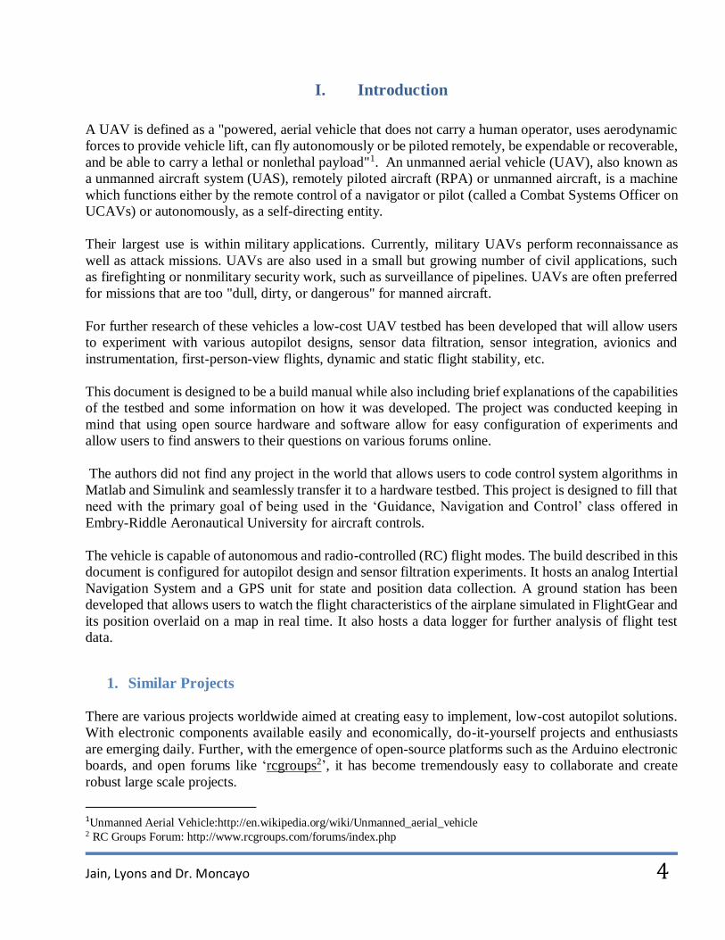
4. Why Arduino11
This section introduces the reader to Arduino products (refer to figure 4). Arduino is an Italian company
that produces these open source electronics prototyping platforms. They are used as the primary and
secondary computers onboard the UAV.
Arduino products, according to one of its creators Massimo Banzi, are “open source physical
computing platforms based on a simple input/output (I/O) board and a development environment that
implements modified C code directly on to the hardware.”
There are many hardware prototyping platforms available, but the authors chose the Arduino platform
because it:
is inexpensive and open source. Therefore, both the software and hardware required are extremely
accessible and can easily be customized to suit our unique purpose.
is capable of using digital and analog inputs, SPI and I2C protocols, a serial interface and can
output digital and digital PWM signals. This makes it extremely versatile.
is easy to use; it connects to a computer via USB and communicates using the standard serial
protocol, runs in standalone mode and as an interface connected to PC/Macintosh computers.
is backed up by a growing on-line community. Plenty of sample source code is already available
and ready to be used. An enormous portion of credit for the success of Arduino and other similar
platforms must be given to a dedicated community of developers, hackers, hobbyists and
professionals who contribute code, documentation, project ideas and significant amounts of
information on the internet.
11 Varesano F., Using Arduino for Tangible Human Computer Interaction, Universitá degli Studi di Torino, April 2011
Jain, Lyons and Dr. Moncayo
11
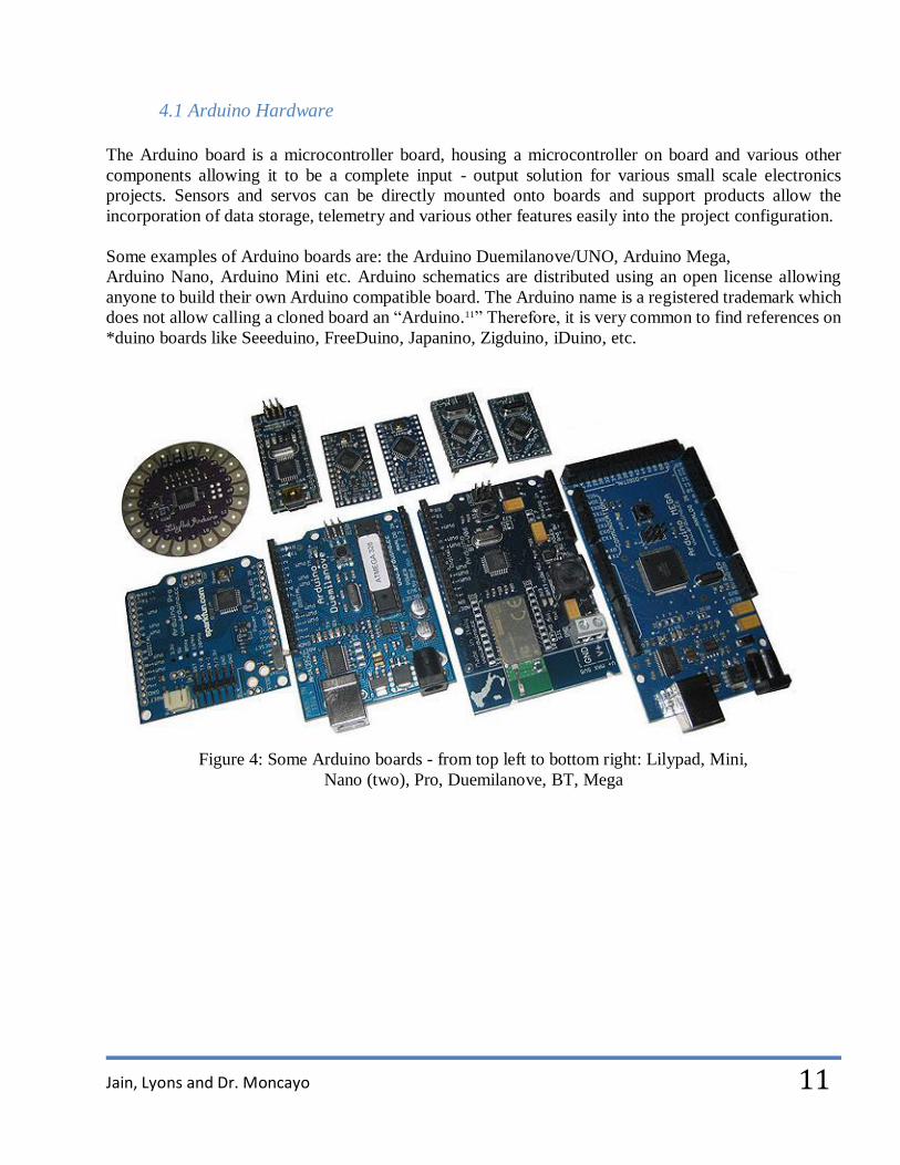
4.1 Arduino Hardware
The Arduino board is a microcontroller board, housing a microcontroller on board and various other
components allowing it to be a complete input - output solution for various small scale electronics
projects. Sensors and servos can be directly mounted onto boards and support products allow the
incorporation of data storage, telemetry and various other features easily into the project configuration.
Some examples of Arduino boards are: the Arduino Duemilanove/UNO, Arduino Mega,
Arduino Nano, Arduino Mini etc. Arduino schematics are distributed using an open license allowing
anyone to build their own Arduino compatible board. The Arduino name is a registered trademark which
does not allow calling a cloned board an “Arduino.11” Therefore, it is very common to find references on
*duino boards like Seeeduino, FreeDuino, Japanino, Zigduino, iDuino, etc.
Figure 4: Some Arduino boards - from top left to bottom right: Lilypad, Mini,
Nano (two), Pro, Duemilanove, BT, Mega

Jain, Lyons and Dr. Moncayo
12
4.2 Explanation of Arduino Hardware
Figure 5: Arduino Duemilanove - Front and back view of the Arduino Duemilanove
Let's have a look at what's inside an Arduino Duemilanove; a board similar to but simpler than an Arduino
Mega. The most important internal components of the board are annotated in figure 5 and they are
described below:
1. FTDI chip. This component enables the Arduino to communicate with the computer through
a USB port. The FTDI chip converts the Serial signals to USB and vice versa. It also has an
internal voltage regulator which converts the 5 V power coming from the USB to 3.3 V
2. Status LED. It is connected to pin 13 with a 1kΩ resistor. Every time a voltage is applied by
the microcontroller to pin 13 the LED will light up.
3. Serial Tx and Rx LEDs. They serve as indicators of a communication link with the any other
serial device.
4. 16 MHz crystal. This acts as a clock source to the micro-controller.
5. Reset button.
6. Power LED (PWR) will light up when the Arduino is connected to any power source. It
indicates that the microcontroller is powered.
7. The microcontroller is the processor onboard the Arduino chip. It is the brain of this chip. The
Duemilanove uses the Atmel ATMEGA 328p, an 8-bit AVR RISC-based microcontroller
which combines 32 KB ISP ash memory with read-while-write capabilities, 1 KB EEPROM,
2 KB SRAM, 23 general purpose I/O lines, 32 general purpose working registers, three
timer/counters with compare modes, internal and external interrupts, serial programmable
USART, a byte-oriented 2-wire serial interface, SPI serial port, a 6-channel 10-bit A/D
converter capable of running up to 200 KHz, programmable watchdog timer with internal
oscillator, and five software selectable power saving modes. The ATMEGA 328p operates
between 2.7-5.5 volts.

Jain, Lyons and Dr. Moncayo
13
4.3 Arduino Shields
Arduino board functionalities can be extended by using shields - ad hoc designed PCBs having the same
pin layout of the microcontroller board, which can be stacked above it to add features that were difficult
to incorporate straight on the chip. Figure 6 shows an example of the various shields available for
Arduinos.
Figure 6: An illustration of Arduino shields
Jain, Lyons and Dr. Moncayo
14
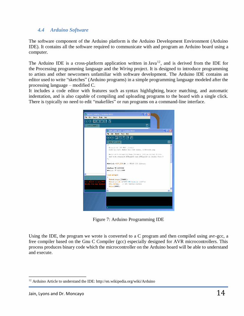
4.4 Arduino Software
The software component of the Arduino platform is the Arduino Development Environment (Arduino
IDE). It contains all the software required to communicate with and program an Arduino board using a
computer.
The Arduino IDE is a cross-platform application written in Java12, and is derived from the IDE for
the Processing programming language and the Wiring project. It is designed to introduce programming
to artists and other newcomers unfamiliar with software development. The Arduino IDE contains an
editor used to write “sketches” (Arduino programs) in a simple programming language modeled after the
processing language – modified C.
It includes a code editor with features such as syntax highlighting, brace matching, and automatic
indentation, and is also capable of compiling and uploading programs to the board with a single click.
There is typically no need to edit “makefiles” or run programs on a command-line interface.
Figure 7: Arduino Programming IDE
Using the IDE, the program we wrote is converted to a C program and then compiled using avr-gcc, a
free compiler based on the Gnu C Compiler (gcc) especially designed for AVR microcontrollers. This
process produces binary code which the microcontroller on the Arduino board will be able to understand
and execute.
12 Arduino Article to understand the IDE: http://en.wikipedia.org/wiki/Arduino

Jain, Lyons and Dr. Moncayo
15
The binary code is then uploaded to the Arduino microcontroller through the USB connection. This is
done using the program “avrdude” which implements the communication protocol used to store programs
into the Arduino program memory.
4.5 Criticism regarding Arduinos
One of the most common criticisms is about the Arduino PCB designs is an additional 0.06”
spacing between the digital pin connectors, making it impossible to connect the Arduino directly
on a breadboard which has 0.1" spaced connectors. For the same reason it's not possible to use
standard prototyping “perfboards” with it. Arduino developers justify this as a simple design flaw
which affected the first versions of Arduino. However, as there were already shields available for
it, they decided to keep the design error for backward compatibility.
It is believed that Arduinos hide inner details of the microcontroller and the compilation
processing details. However, it is actually possible to program Arduinos without using the API
and directly interact with the microcontroller11.
The computation power onboard these chips is severely limited. More powerful computing
architecture is available in 32 bit Advanced RISC Machine (ARM) cortex based microcontroller
versions, such as the chipkit chipset.
Even with its limitations, Arduinos are very good prototyping platforms. The advantages: simplicity of
use and easily available information, far exceed the aforementioned deficiencies.

Jain, Lyons and Dr. Moncayo
16
5. Analog IMU
The states of an aircraft are usually calculated using an Inertial Navigation System (INS) using a device
called an Inertial Measurement Unit (IMU).
While it is possible to obtain digital IMU units which will process incoming sensor data and provide the
states directly to the user, one of the goals of this project was to understand data filtration and analog
communication protocols. Therefore a 6 Degree of Freedom (6DoF) analog IMU called the ‘6DOF Ultra-
Thin IMU Razor’13 was used.
The 6DOF Razor makes use of two gyros, and a triple-axis accelerometer, to allow us to calculate p, q,
r, Φ, Θ and Ψ state variables of the vehicle.
All analog outputs of the gyros (1x and 4x amplified) and accelerometer are broken out to the 0.1" pitch
headers. The gyro outputs have a full scale of ±300°/s, while the outputs of the accelerometer have ±3g
range.
There is no on-board voltage regulation, so the user will need to provide a clean 3.3VDC power source,
which will power all three sensors. All filtering capacitors and other components are included in the
device as shown in figure 8.
Figure 8: 6DOF Ultra-Thin IMU Razor
Various different explanations about the workings of gyros and accelerometers are available online and,
the authors found “the instructables tutorial14” most useful.
It is recommended that a magnetometer be incorporated along with this IMU to acquire accurate yaw
measurements.
The code required to extract the analog data via Simulink has been detailed in Appendix C. While this
code was being developed, the biggest challenge was found to be the creation of simple filtration
algorithms that low-cost electronics could handle while also allowing accurate enough data collection for
an effective autopilot algorithm.
13 IMU Analog Combo Board Razor – 6DOF Ultra-Thin IMU: http://www.sparkfun.com/products/10010 14 Accelerometer-Gyro Tutorial: http://www.instructables.com/id/Accelerometer-Gyro-Tutorial/

Jain, Lyons and Dr. Moncayo
17
The most common filters for Inertial navigation systems include Kalman filters15and Complementary
filters16.
The authors found that a complementary filter implemented using a low pass filter for the accelerometer
data and a high pass filter for the gyro data worked very well for their purposes. However, Simulink
requires continuous data to be passed to its generic low pass and high pass filter blocks and Arduino
boards cannot handle continuous data processing.
Therefore a discrete low-pass filter was computed using the derivation in this paper17.
The Laplace transform transfer function - also denoting the continuous-time transfer function - of a first
order low pass filter is:
𝐻(𝑠) = 𝑦(𝑠)
𝑢(𝑠)=
1
𝑇𝑓𝑠 + 1
where Tf (s) is the time-constant. u is filter input, and y is filter output.
This provides the formulation of a discrete low pass filter;
𝑦(𝑡𝑘) = (1 − a)y(t𝑘−1 ) + 𝑎. 𝑢(𝑡𝑘)
Where the present filter output y(tk) is a function of the present filter input u(tk) and the filter output at
the previous discrete time, y(tk−1). The filter parameter is,
𝑎 = ℎ
𝑇𝑓 + ℎ
Here, h is the time constant and,
ℎ ≤ 𝑇𝑓
5.
Further, using the same derivation process, the Laplace transform transfer function - also denoted the
continuous-time transfer function - of a first order high pass filter is:
𝐻(𝑠) = 𝑦(𝑠)
𝑢(𝑠)=
𝑇𝑓𝑠
𝑇𝑓𝑠 + 1
Where Tf (s) is the time-constant. u is filter input, and y is filter output.
Solving this gives us the formulation of a discrete high pass filter:
𝑦(𝑡𝑘) = (1 − a)y(t𝑘−1 ) + 𝑎d(u(t𝑘))
𝑑𝑡. ℎ
With the same parameters as mentioned for the low pass filter.
15 Kalman Filter Explanation: http://en.wikipedia.org/wiki/Kalman_filter 16 Filtration Explanation: http://web.mit.edu/scolton/www/filter.pdf 17 Discrete Filter Algorithm: http://techteach.no/simview/lowpass_filter/doc/filter_algorithm.pdf

Jain, Lyons and Dr. Moncayo
18
These discrete filter formulations were implemented in Simulink code and proved to work well.
The following table uses the roll variable (q) to illustrate various filtration techniques that the authors
tried. The user is advised to try to recreate these filters and notice if his/her conclusions agree with the
authors’ observations. Surprisingly, the Kalman filter wasn’t as effective as a Complementary filter
during testing but the authors believe that a Kalman filter can be tuned and refined to give much better
performance than demonstrated here.
Table 1: Raw and filtered Roll Data
(from accelerometer, gyroscope and fusion algorithms)
Data Roll Data Comments
Biased (raw)
Accelerometer
Data
Notice
magnitude and
noise levels
Biased (raw)
Gyrometer
Data
Notice
magnitude and
noise levels

Jain, Lyons and Dr. Moncayo
19
Computed
Acelerometer
Data
The magnitude
still exceeds
90º
Computed
Gyrometer
Data
Values are
drifting away
from 0º
Kalman
Filtered roll
values
Drift Still
Persists

Jain, Lyons and Dr. Moncayo
20
Continuous
Complementary
Filtered roll
values
Good readings.
However
Arduino
cannot handle
continuous
computations.
Discrete
Complementary
Filtered roll
values
Acceptable
discretized
complementary
filter readings.
Jain, Lyons and Dr. Moncayo
21
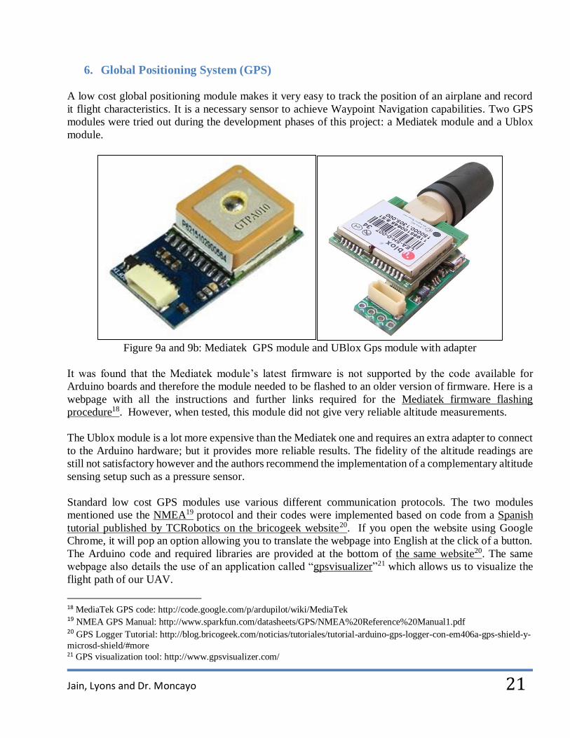
6. Global Positioning System (GPS)
A low cost global positioning module makes it very easy to track the position of an airplane and record
it flight characteristics. It is a necessary sensor to achieve Waypoint Navigation capabilities. Two GPS
modules were tried out during the development phases of this project: a Mediatek module and a Ublox
module.
Figure 9a and 9b: Mediatek GPS module and UBlox Gps module with adapter
It was found that the Mediatek module’s latest firmware is not supported by the code available for
Arduino boards and therefore the module needed to be flashed to an older version of firmware. Here is a
webpage with all the instructions and further links required for the Mediatek firmware flashing
procedure18. However, when tested, this module did not give very reliable altitude measurements.
The Ublox module is a lot more expensive than the Mediatek one and requires an extra adapter to connect
to the Arduino hardware; but it provides more reliable results. The fidelity of the altitude readings are
still not satisfactory however and the authors recommend the implementation of a complementary altitude
sensing setup such as a pressure sensor.
Standard low cost GPS modules use various different communication protocols. The two modules
mentioned use the NMEA19 protocol and their codes were implemented based on code from a Spanish
tutorial published by TCRobotics on the bricogeek website20. If you open the website using Google
Chrome, it will pop an option allowing you to translate the webpage into English at the click of a button.
The Arduino code and required libraries are provided at the bottom of the same website20. The same
webpage also details the use of an application called “gpsvisualizer”21 which allows us to visualize the
flight path of our UAV.
18 MediaTek GPS code: http://code.google.com/p/ardupilot/wiki/MediaTek 19 NMEA GPS Manual: http://www.sparkfun.com/datasheets/GPS/NMEA%20Reference%20Manual1.pdf 20 GPS Logger Tutorial: http://blog.bricogeek.com/noticias/tutoriales/tutorial-arduino-gps-logger-con-em406a-gps-shield-y-
microsd-shield/#more 21 GPS visualization tool: http://www.gpsvisualizer.com/

Jain, Lyons and Dr. Moncayo
22
7. Servo Controller
The authors used a Pololu Servo Controller22 because they were having difficulty getting Simulink to
generate the proper pulse width modulated signals, required to run servos, directly using the Arduino
PWM channels. The Pololu Servo Controller is extremely simple to use, it has various features and a
very thorough user’s guide23.
However, the authors noted one programming glitch when using this product. If Matlab is trying to
compile a program onto the Arduino and finds that the particular program already exists in the chip’s
memory, it aborts the compilation and displays an ‘Application already exists’ error. While this allows
the Arduino to continue functioning smoothly, the servos don’t seem to be getting any commands from
the autopilot. This is because when Matlab refuses to recompile a program that already exists on the
Arduino’s memory, it also allows the Pololu servo controller chip’s remnant memory to remain
unchanged.
Unfortunately the Pololu servo controller does not recognize a program that was compiled earlier and it
won’t respond to the commands being delivered by the Arduino. To avoid this problem, it is
recommended that users make a slight change in the Simulink code that they are compiling to the Arduino
every time they are testing the system with the servo controller in place. The change can be as minute as
disconnecting and reconnecting a Simulink connector arrow within the program or adding in a simple
new comment. This will force Matlab to recompile to the Arduino and solve the problem.
Figure 10: Pololu 18 Channel Servo Controller
22 Servo Controller: http://www.pololu.com/catalog/category/12 23 Pololu Servo Controller User’s guide: http://www.pololu.com/docs/0J40

Jain, Lyons and Dr. Moncayo
23
8. Multiplexer The servo controller was used along with a very easy to use Pololu multiplexer24 to switch from flying
in RC mode to autonomous mode by toggling a single switch on the RC controller. However, since the
multiplexer (mux) was available with only 4 channels, it became the limiting factor in the number of
channels accessible to the RC pilot and the autopilot algorithm.
Therefore it is recommended that users incorporate two parallel multiplexers to increase the number of
accessible channel or buy a simple 6 channel Servo controller board instead of the 18 channel one that
the authors bought.
Figure 11: Pololu 4 channel Servo Multiplexer
9. Telemetry
Transmitting real-time data allows the Ground Control Station (GCS) to accurately represent the UAV
state on FlightGear even after it has flown past the range of sight. Therefore, setting up and testing a
telemetry system is a good idea prior to the first autonomous flight. The Telemetry system should have
a state indicator indicating whether all systems are functional. Thus, the RC pilot will know when it is
acceptable to switch the UAV from RC to autonomous mode.
For this project, low-cost wireless communication devices called XBee Pro25 modules were used for
communications between the UAV and the GCS. The UAV part list in Appendix A includes XBee Pro
modules and a breakout board as illustrated in figure 12a and 12b.
24 Multiplexer: http://www.pololu.com/catalog/product/721 25 XBee Pro Page: http://www.digi.com/products/wireless-wired-embedded-solutions/zigbee-rf-modules/point-multipoint-
rfmodules/xbee-pro-xsc#overview

Jain, Lyons and Dr. Moncayo
24
Figure 12 a and 12b: XBee Pro Module and Breakout Board
These modules allow a very reliable and simple communication between microcontrollers, computers,
toys, really anything with a serial port. Point to point and multi-point networks are supported.
The modules’ ability to talk to multiple modems during flight condition creates the risk that data packets
might get diverted to different vehicles using the same channels within the link range. Particular care
needs to be taken when channels and PAN IDs are being set between the XBee modules to avoid this
condition. As always it is recommended that various simple ground tests be conducted before the part is
incorporated onto the airframe electronics to ensure that the users understand the nuances of setting these
modules up.
The authors ran the test prototype at 115200 BAUD rate and the channels described in tutorial one26.
Tutorials two27 and three28 are also great aides to understand XBee pairing and set-up.
10. Logging Data
A Micro SD card data logger29 is a useful tool to record flight data. Testing the RC aircraft with the
required IMU and GPS sensors and logging the flight data will allow users to characterize the flight
properties of their particular aircraft model. Using this data, they can begin the parameter identification
process for their autopilot algorithms.
The authors’ code was adapted from the Bricogeek project code20 and allows it to record IMU and GPS
data. Other sample codes are easily available to record data into these modules and here’s30 the quick
start guide to a very popular device in this category.
26 Detailed Tutorials one and two for XBee Pairing and set-up: http://forums.trossenrobotics.com/tutorials/how-to-diy-
128/xbee-basics-3259/ 27 https://sites.google.com/site/xbeetutorial/ 28 Xbee Tutorial: http://www.tristantech.net/articles/xbee_tutorial/1.php 29 SD card Module: http://www.bizoner.com/arduino-sd-card-module-for-sd-card-memory-read-and-write-p-184.html 30 http://www.sparkfun.com/tutorials/172
Jain, Lyons and Dr. Moncayo
25
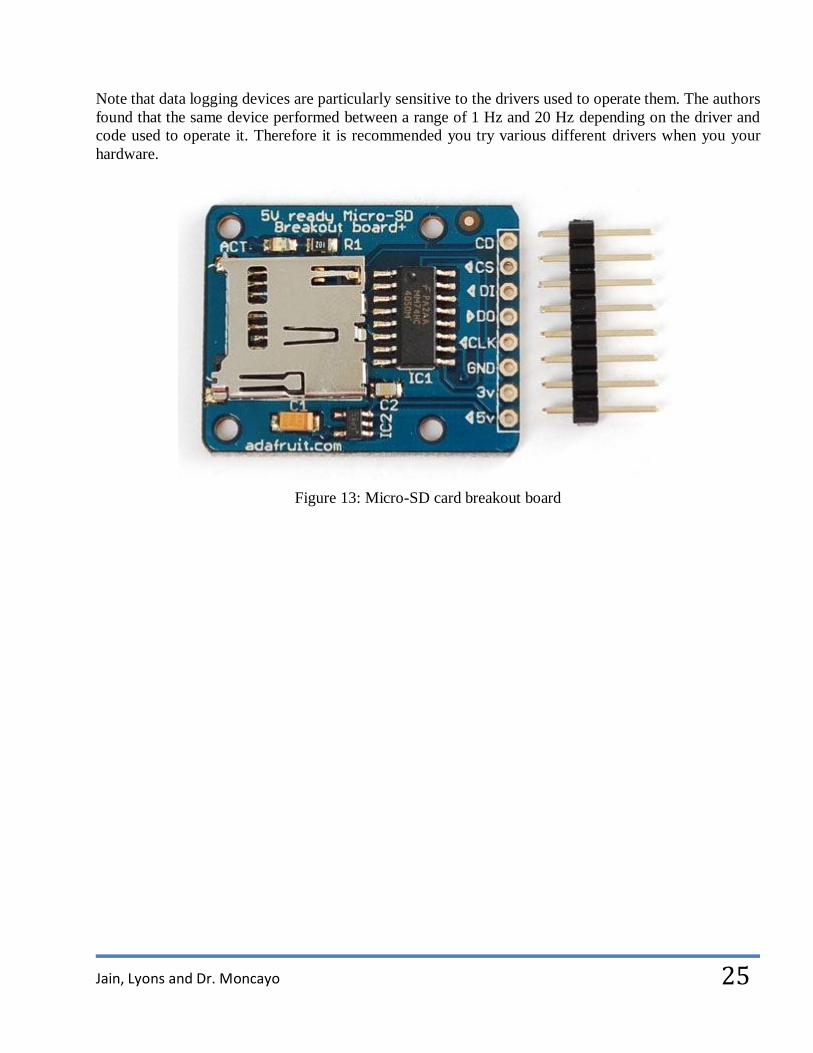
Note that data logging devices are particularly sensitive to the drivers used to operate them. The authors
found that the same device performed between a range of 1 Hz and 20 Hz depending on the driver and
code used to operate it. Therefore it is recommended you try various different drivers when you your
hardware.
Figure 13: Micro-SD card breakout board

Jain, Lyons and Dr. Moncayo
26
III. Algorithms and Codes
1. Simulink Support for Arduino
The Simulink Support Package for Arduino (also called the ‘Target’) allows you to compile code that
will run autonomously on your Arduino board. Its primary purpose is to translate Simulink programs to
the modified C code used in Arduino boards. It is a great tool that allows Simulink users to conduct
hardware-in-the-loop (HIL) and processor in the loop (PIL) simulations on Arduino boards as well as
allowing autonomous programs to be compiled and run on the boards during flight. Here is the link to
download the Target31.
2. Target Limitations
Newer versions of the target release regularly. The following information may or may not apply to
newer versions after October 2011. All the information presented here refers to the initial Target
released on February 03, 2011.
The initial Target allows read and write operations only to the Arduino’s analog and digital I/O
channels. Therefore to write PWM signals to the servo, a servo controller board is used in the
UAV.
The support configurations work better for Microsoft Windows 32-bit and it is recommended that
users choose to compile their files using a 32 bit compiler such as the Bloodshed Dev-C++32 or
the Microsoft Visual C++ 2010 Express edition33. There are various other options available free
of charge on this compiler list34.
Mathworks suggests that the support package be used with the Arduino Duemilanove board
however it is possible to use the target for other boards like the Uno and the Arduino Mega 1280.
It was found that the latest Arduino Mega 2560 board has a different programming protocol than
that supported by the target and therefore the fastest board that can currently be used remains the
Arduino Mega 1280. This is done by declaring that the upload (baud) rates for different Arduino
boards are different based on the processor they use. Details on how to configure the target
settings are as follows:
o Find the prefs.m file in the Arduino Target folder:
ARDUINO_TARGET\arduino\+Arduino
o Then edit the file by modifying the loop called “switch mcu” as displayed in figure 14a:
31 Simulink Support for Arduino Download website: http://www.mathworks.com/academia/arduino-software/arduino-
simulink.html 32 Bloodshed dev C++: http://www.bloodshed.net/devcpp.html 33 Visual Studio 2010 Express: http://www.microsoft.com/visualstudio/en-us/products/2010-editions/express 34 C++Compiler list: http://www2.research.att.com/~bs/compilers.html

Jain, Lyons and Dr. Moncayo
27
Figure 14a: Setting up Simulink Support Package for Arduino
Now find the primary Readme file in the Arduino Target package:
ARDUINO_TARGET\README.txt
Modify it to reflect the setMcu value you intend to use as displayed in figure 14b:
Figure 14b: Setting up Simulink Support Package for Arduino
Notice also that in the above figure the Arduino.Prefs.setArduinoPath(..) has been preceded by path(path,
‘E:\...’) commands. The path addresses reflect where the ARDUINO_TARGET folder was extracted and
will vary from user to user. The additional statements were added simply to quicken the process of adding
the arduino and blocks folders to the Matlab path as required in the README.txt file in section 3 as
displayed in figure 14c:

Jain, Lyons and Dr. Moncayo
28
Figure 14c: Setting up Simulink Support Package for Arduino
3. Target Observations
As with any new compiler or translation software, it was found that the Target works very well after the
initial stages of configuration have been successfully completed. The following observations made during
this project might help the user avoid common and often time-consuming pitfalls:
1) The Code generator will not work if the user has forgotten to choose arduino.tlc and other settings
for the compiler, in the model’s configuration parameters, as displayed in figure 14d. Please
ensure this setting is correct in the first few attempts to compile code on the Arduino.
To avoid this problem it is recommended that users take the target’s .mdl template files
from examples in the Target package.
Then delete the contents of the file and incorporate their program/code into the window.
This will enable the user to use the pre-programmed compiler settings for different types
of programs as intended to be used by Mathworks.
Note that PIL files are differently configured from normal HIL or independent
Arduino_Target files. Which means that when creating a PIL simulation, a working PIL
template should be specifically chosen and modified from the working examples. If one
is simply building a code into the Arduino board then one should use a normal (non PIL)
working model that can be built into the board by using the keys ‘Ctrl+B’

Jain, Lyons and Dr. Moncayo
29
Figure 14d: Setting up Simulink Support Package for Arduino
2) The demo_arduino_blink example as listed in the primary README.txt doesn’t always work. It
is useful to check the demo_arduino_pil and other examples to see if the configuration settings
are working.
3) Matlab 2011b supports the compilation of Processor in the Loop programs to Arduino boards.
Versions prior to 2011b can use the newest target block for all other purposes.
4) The most common mistake the authors made during the Arduino Target configuration was while
choosing the baud rate for the boards being used. Therefore ensure that the setMcu value in the
.prefs file for your chosen board is correct by comparing the values in your file with those in the
baud table found in Appendix B.
Jain, Lyons and Dr. Moncayo
30
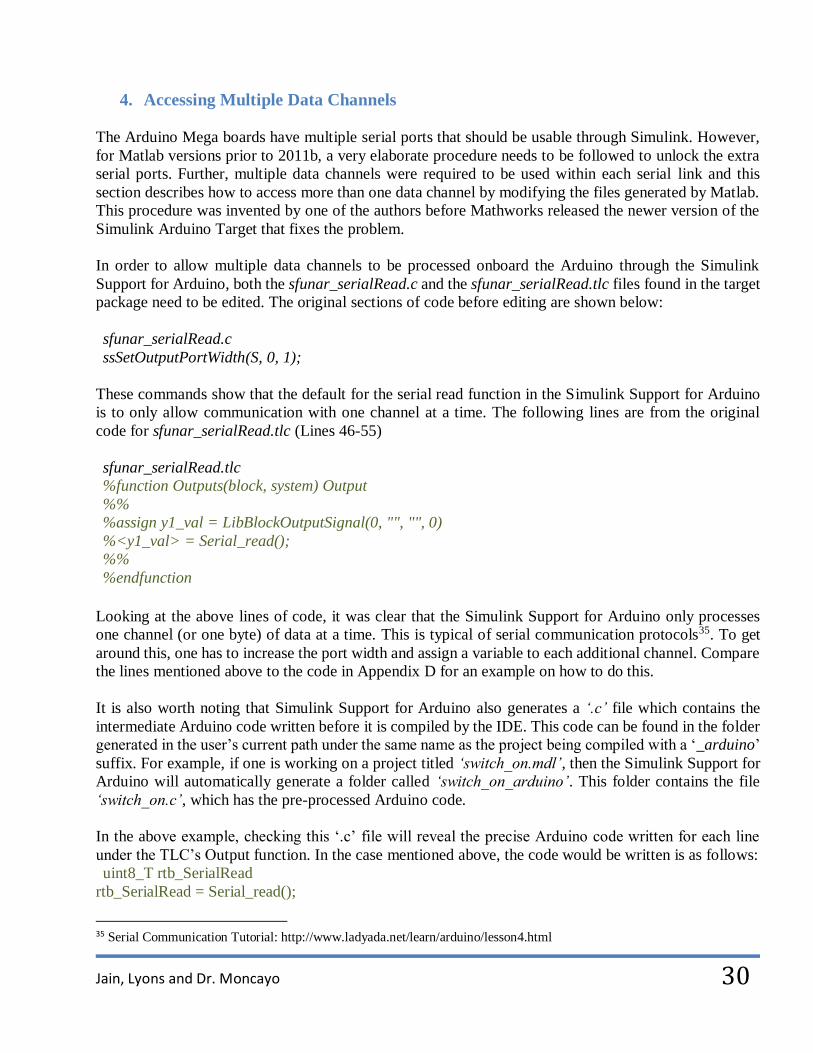
4. Accessing Multiple Data Channels
The Arduino Mega boards have multiple serial ports that should be usable through Simulink. However,
for Matlab versions prior to 2011b, a very elaborate procedure needs to be followed to unlock the extra
serial ports. Further, multiple data channels were required to be used within each serial link and this
section describes how to access more than one data channel by modifying the files generated by Matlab.
This procedure was invented by one of the authors before Mathworks released the newer version of the
Simulink Arduino Target that fixes the problem.
In order to allow multiple data channels to be processed onboard the Arduino through the Simulink
Support for Arduino, both the sfunar_serialRead.c and the sfunar_serialRead.tlc files found in the target
package need to be edited. The original sections of code before editing are shown below:
sfunar_serialRead.c
ssSetOutputPortWidth(S, 0, 1);
These commands show that the default for the serial read function in the Simulink Support for Arduino
is to only allow communication with one channel at a time. The following lines are from the original
code for sfunar_serialRead.tlc (Lines 46-55)
sfunar_serialRead.tlc
%function Outputs(block, system) Output
%%
%assign y1_val = LibBlockOutputSignal(0, "", "", 0)
%<y1_val> = Serial_read();
%%
%endfunction
Looking at the above lines of code, it was clear that the Simulink Support for Arduino only processes
one channel (or one byte) of data at a time. This is typical of serial communication protocols35. To get
around this, one has to increase the port width and assign a variable to each additional channel. Compare
the lines mentioned above to the code in Appendix D for an example on how to do this.
It is also worth noting that Simulink Support for Arduino also generates a ‘.c’ file which contains the
intermediate Arduino code written before it is compiled by the IDE. This code can be found in the folder
generated in the user’s current path under the same name as the project being compiled with a ‘_arduino’
suffix. For example, if one is working on a project titled ‘switch_on.mdl’, then the Simulink Support for
Arduino will automatically generate a folder called ‘switch_on_arduino’. This folder contains the file
‘switch_on.c’, which has the pre-processed Arduino code.
In the above example, checking this ‘.c’ file will reveal the precise Arduino code written for each line
under the TLC’s Output function. In the case mentioned above, the code would be written is as follows:
uint8_T rtb_SerialRead
rtb_SerialRead = Serial_read();
35 Serial Communication Tutorial: http://www.ladyada.net/learn/arduino/lesson4.html

Jain, Lyons and Dr. Moncayo
31
It should be clear that only one byte of data is being read by the Arduino. To add additional channels to
the serial read TLC and the C files, the following lines must be added to this pre-processed Arduino code
for every extra channel desired:
Uint8_T rtb_SerialRead[2]
rtb_SerialRead[0] = Serial_read();
rtb_SerialRead[1] = Serial_read();
Now the Arduino will read additional channels as an array and will index each value correctly as it is
accessed during the simulation.
Note that only one byte at a time can be read by the serial port hence the ‘uint8_T’. See Appendix D on
how to edit the sfunar_serialRead.c and sfunar_serialRead.tlc files to read 26 bytes at a time. Please
note, that if using correct TLC programming syntaxes, a simple loop could be used to streamline the
process of adding multiple channels. However, the authors did not have the time to learn TLC
programming in depth, and added each channel individually (see Appendix D).
5. Accessing Multiple Serial Ports
In order to access multiple serials it was necessary to modify two files: io_wrappers.h and
io_wrappers.cpp. These library files are required to link C code to C++ methods that are not supported
by C. The original code contained within these files only allowed the main serial port (Serial 0) onboard
the Arduino to be accessed by the simulation. This option is suitable for smaller Arduino boards such as
the Dueminalove or the UNO. However, the UAV test-bed requires the use of the Arduino Mega which
has four serials available. Therefore, in addition to the default Serial 0 lines, the following lines were
added to the files mentioned above:
(in io_wrappers.h)
int Serial1_begin(long r);
int Serial1_read(void);
int Serial1_available(void);
void Serial1_write(uint8_t * c, size_t s);
int Serial2_begin(long r);
int Serial2_read(void);
int Serial2_available(void);
int Serial3_begin(long r);
int Serial3_read(void);
int Serial3_available(void);

Jain, Lyons and Dr. Moncayo
32
(in io_wrappers.cpp)
extern "C" int Serial1_begin(long r) Serial1.begin(r);
extern "C" int Serial1_read(void) return Serial1.read();
extern "C" void Serial1_write(uint8_t * c, size_t s) Serial1.write(c, s);
extern "C" int Serial1_available(void) return Serial1.available();
extern "C" int Serial2_begin(long r) Serial2.begin(r);
extern "C" int Serial2_read(void) return Serial2.read();
extern "C" int Serial2_available(void) return Serial2.available();
extern "C" void Serial2_write(uint8_t * c, size_t s) Serial2.write(c, s);
extern "C" int Serial3_begin(long r) Serial3.begin(r);
extern "C" int Serial3_read(void) return Serial3.read();
extern "C" int Serial3_available(void) return Serial3.available();
extern "C" void Serial3_write(uint8_t * c, size_t s) Serial3.write(c, s);
Here the user is adding additional keywords to the TLC database, these are utilized in the preprocessed
Arduino code mentioned in the previous section.
Note: these keywords are only recognized by the Arduino Mega and will cause an error if left
uncommented when uploading to other Arduino boards which do not have multiple serials.

Jain, Lyons and Dr. Moncayo
33
6. Ground Control Station
The Ground Control Station (GCS) was designed to incorporate all the basic features required to track
and graphically represent the UAV during flight.
It communicates with the UAV via the XBee modules, acquires IMU data and resolves it to acquire the
state variables of the aircraft. It acquires position and velocity data from the GPS. Using this information
the aircraft is represented in real time in a FlightGear36 model.
Further, it tracks the position of the aircraft on a map using a separate application designed to display the
location of the vehicle based on data received from the GPS.
As long as the aircraft can communicate with the ground station with a reliable telemetry system, this
aircraft may safely be operated outside of line of sight because of the ground station’s ability to represent
the state and position of the aircraft.
36 Flightgear Home Page: http://www.flightgear.org/
Jain, Lyons and Dr. Moncayo
34
IV. Conclusion
The UAV project was successfully completed in December 2011. The resultant vehicle can be
duplicated by studying this document carefully and it has been designed to cost less than $600 in parts
excluding shipping charges.
As of March 2012, three such vehicles are being flown by students of Embry-Riddle Aeronautical
University in the Daytona Beach campus, Florida and in Gulfstream headquarters in Savannah,
Georgia.
They are being used to teach a course called “Guidance, Navigation and Control” which introduces
students to topics such as hardware in the loop simulations, processor in the loop simulations, sensor
integration, data filtration techniques, etc.
It is also serving well as a test-bed to validate autopilot algorithms written by students.
1. Project Limitations
This project has physical and software limitations stemming from its execution under demanding
deadlines and its aim at being a low-cost testing platform. Some of the current limitations observed by
the authors are as follows:
The IMU does not provide reliable yaw measurements.
The GPS unit does not provide reliable altitude readings.
The RC Skywalker has FPV capability that is not being utilized by this UAV.
Lack of redundant systems does not allow such a configuration of hardware on board
expensive vehicles because of reliability issues.
2. Future Work
The authors can think of various aspects about the project that can be improved. Most of these are fairly
easy to implement and can enhance the UAV’s performance significantly. Here are some
recommendations for future work:
Incorporating a magnetometer and fusing the IMU readings with magnetometer readings
will allow the user to acquire better yaw measurements.
Incorporating a pressure sensor and fusing its readings with the GPS altitude data will
provide better altitude measurements.

Jain, Lyons and Dr. Moncayo
35
The processing power and memory capacity of the Arduino Mega 1280 is lower than
that of the newer Arduino Mega 2560. These boards can be used instead of the Arduino
Mega 1280 boards using the latest release of Simulink Support for Arduino to enhance
the UAV’s performance.
Incorporating off the shelf FPV hardware will greatly enhance the capabilities of this
UAV and make it more enjoyable for the Pilot to fly. It will also allow users to
understand the performance characteristics of the UAV by studying the incoming video
stream for vibration effects or unexpected performance characteristics (jerky turns, dutch
roll motion, etc.
An ideal solution is still desired to robustly hold all the wiring and electronics on board
the UAV. Fixing that will enhance the reliability of the vehicle greatly.
Coding the UAV to allow the user to make changes to the control laws remotely could
allow for some interesting research opportunities.
Jain, Lyons and Dr. Moncayo
36
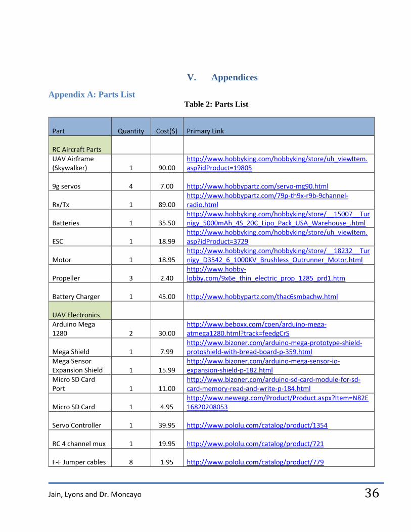
V. Appendices
Appendix A: Parts List Table 2: Parts List
Part Quantity Cost($) Primary Link
RC Aircraft Parts
UAV Airframe (Skywalker) 1 90.00
http://www.hobbyking.com/hobbyking/store/uh_viewItem.asp?idProduct=19805
9g servos 4 7.00 http://www.hobbypartz.com/servo-mg90.html
Rx/Tx 1 89.00 http://www.hobbypartz.com/79p-th9x-r9b-9channel-radio.html
Batteries 1 35.50 http://www.hobbyking.com/hobbyking/store/__15007__Turnigy_5000mAh_4S_20C_Lipo_Pack_USA_Warehouse_.html
ESC 1 18.99 http://www.hobbyking.com/hobbyking/store/uh_viewItem.asp?idProduct=3729
Motor 1 18.95 http://www.hobbyking.com/hobbyking/store/__18232__Turnigy_D3542_6_1000KV_Brushless_Outrunner_Motor.html
Propeller 3 2.40 http://www.hobby-lobby.com/9x6e_thin_electric_prop_1285_prd1.htm
Battery Charger 1 45.00 http://www.hobbypartz.com/thac6smbachw.html
UAV Electronics
Arduino Mega 1280 2 30.00
http://www.beboxx.com/coen/arduino-mega-atmega1280.html?track=feedgCrS
Mega Shield 1 7.99 http://www.bizoner.com/arduino-mega-prototype-shield-protoshield-with-bread-board-p-359.html
Mega Sensor Expansion Shield 1 15.99
http://www.bizoner.com/arduino-mega-sensor-io-expansion-shield-p-182.html
Micro SD Card Port 1 11.00
http://www.bizoner.com/arduino-sd-card-module-for-sd-card-memory-read-and-write-p-184.html
Micro SD Card 1 4.95 http://www.newegg.com/Product/Product.aspx?Item=N82E16820208053
Servo Controller 1 39.95 http://www.pololu.com/catalog/product/1354
RC 4 channel mux 1 19.95 http://www.pololu.com/catalog/product/721
F-F Jumper cables 8 1.95 http://www.pololu.com/catalog/product/779

Jain, Lyons and Dr. Moncayo
37
Xbee modules 2 37.95 http://www.sparkfun.com/products/8690
Xbee module breakout board 1 9.95 http://www.sparkfun.com/products/9132
Battery port cable 2 2.99 http://www.bizoner.com/9v-power-cable-for-arduino-mega-arduino-duemilanovearduino-uno-p-191.html
Total (excluding shipping) 599.90

Jain, Lyons and Dr. Moncayo
38
Appendix B: Component list with Baud Rates
Table 3: Component list with common Baud Rates Device / Processor Common Baud Comments
Atmega168 19200
Arduino Uno 115200
Arduino Duemilanove
‘atmega328p’
57600
Arduino Duemilanove
‘atmega328p-pu’
115200
Arduino Mega 57600 The basic ‘mega’ has an atmega1280 processor
Arduino Mega 2560 ? Can be used with Simulink only with Matlab 2011b + and the new support package decides this number by itself
Mediatek GPS 38400 Using NMEA protocol
UBlox GPS 38400 Using NMEA protocol
Micro SD card logger ? Dependent on hardware and driver being used
Analog IMU N/A
Servo Controller N/A Pololu user guide: http://www.pololu.com/docs/0J40
Multiplexer N/A
Jain, Lyons and Dr. Moncayo
39
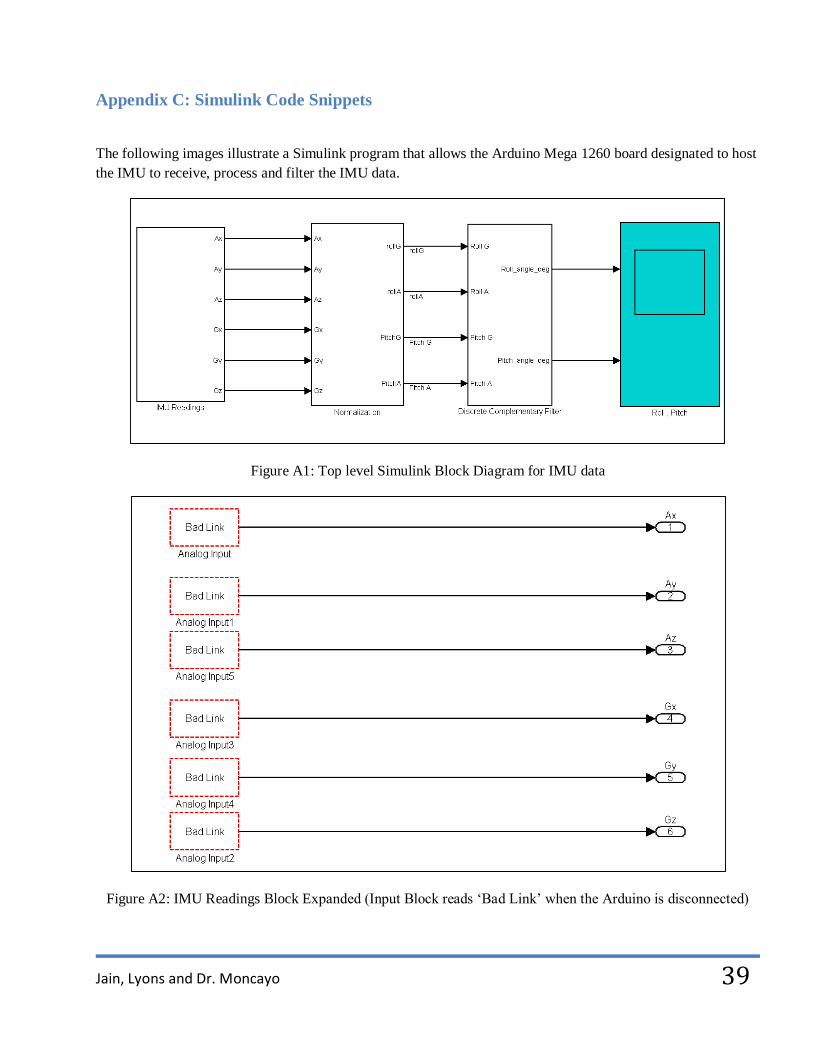
Appendix C: Simulink Code Snippets
The following images illustrate a Simulink program that allows the Arduino Mega 1260 board designated to host
the IMU to receive, process and filter the IMU data.
Figure A1: Top level Simulink Block Diagram for IMU data
Figure A2: IMU Readings Block Expanded (Input Block reads ‘Bad Link’ when the Arduino is disconnected)

Jain, Lyons and Dr. Moncayo
40
Figure A3: Expanded view of the Normalization Block
Figure A4: Expanded Discrete Complementary Filter Block

Jain, Lyons and Dr. Moncayo
41
Figure A5: Expanded Discrete High Pass Filter Block
Figure A6: Expanded Discrete Low Pass Filter Block
Figure A7: Model Properties required to set the initialization procedure

Jain, Lyons and Dr. Moncayo
42
Appendix D: Code required to modify the .tlc files generated by Matlab
Edited C code Used to Process 26 bytes of Data for IMU and GPS
ssSetOutputPortWidth(S, 0, 26);
Edited TLC code Used to Process 26 bytes of Data for IMU and GPS
%function Outputs(block, system) Output
%%
%assign y1_val = LibBlockOutputSignal(0, "", "", 0)
%assign y2_val = LibBlockOutputSignal(0, "", "", 1)
%assign y3_val = LibBlockOutputSignal(0, "", "", 2)
%assign y4_val = LibBlockOutputSignal(0, "", "", 3)
%assign y5_val = LibBlockOutputSignal(0, "", "", 4)
%assign y6_val = LibBlockOutputSignal(0, "", "", 5)
%assign y7_val = LibBlockOutputSignal(0, "", "", 6)
%assign y8_val = LibBlockOutputSignal(0, "", "", 7)
%assign y9_val = LibBlockOutputSignal(0, "", "", 8)
%assign y10_val = LibBlockOutputSignal(0, "", "", 9)
%assign y11_val = LibBlockOutputSignal(0, "", "", 10)
%assign y12_val = LibBlockOutputSignal(0, "", "", 11)
%assign y13_val = LibBlockOutputSignal(0, "", "", 12)
%assign y14_val = LibBlockOutputSignal(0, "", "", 13)
%assign y15_val = LibBlockOutputSignal(0, "", "", 14)
%assign y16_val = LibBlockOutputSignal(0, "", "", 15)
%assign y17_val = LibBlockOutputSignal(0, "", "", 16)
%assign y18_val = LibBlockOutputSignal(0, "", "", 17)
%assign y19_val = LibBlockOutputSignal(0, "", "", 18)
%assign y20_val = LibBlockOutputSignal(0, "", "", 19)
%assign y21_val = LibBlockOutputSignal(0, "", "", 20)
%assign y22_val = LibBlockOutputSignal(0, "", "", 21)
%assign y23_val = LibBlockOutputSignal(0, "", "", 22)
%assign y24_val = LibBlockOutputSignal(0, "", "", 23)
%assign y25_val = LibBlockOutputSignal(0, "", "", 24)
%assign y26_val = LibBlockOutputSignal(0, "", "", 25)
%%
%%GPS
%<y1_val> = Serial_read();
%<y2_val> = Serial_read();
%<y3_val> = Serial_read();
%<y4_val> = Serial_read();
%<y5_val> = Serial_read();
%<y6_val> = Serial_read();
%<y7_val> = Serial_read();
%<y8_val> = Serial_read();

Jain, Lyons and Dr. Moncayo
43
%<y9_val> = Serial_read();
%<y10_val> = Serial_read();
%<y11_val> = Serial_read();
%<y12_val> = Serial_read();
%<y13_val> = Serial_read();
%<y14_val> = Serial_read();
%%IMU
%<y15_val> = Serial_read();
%<y16_val> = Serial_read();
%<y17_val> = Serial_read();
%<y18_val> = Serial_read();
%<y19_val> = Serial_read();
%<y20_val> = Serial_read();
%<y21_val> = Serial_read();
%<y22_val> = Serial_read();
%<y23_val> = Serial_read();
%<y24_val> = Serial_read();
%<y25_val> = Serial_read();
%<y26_val> = Serial_read(); %%
%endfunction
Above Code Converted to Arduino Code by Simulink Support for Arduino
uint8_T rtb_SerialRead[26];
/* S-Function (sfunar_serialRead): '<Root>/Serial Read' */
rtb_SerialRead[0] = Serial_read();
rtb_SerialRead[1] = Serial_read();
rtb_SerialRead[2] = Serial_read();
rtb_SerialRead[3] = Serial_read();
rtb_SerialRead[4] = Serial_read();
rtb_SerialRead[5] = Serial_read();
rtb_SerialRead[6] = Serial_read();
rtb_SerialRead[7] = Serial_read();
rtb_SerialRead[8] = Serial_read();
rtb_SerialRead[9] = Serial_read();
rtb_SerialRead[10] = Serial_read();
rtb_SerialRead[11] = Serial_read();
rtb_SerialRead[12] = Serial_read();
rtb_SerialRead[13] = Serial_read();
rtb_SerialRead[14] = Serial_read();
rtb_SerialRead[15] = Serial_read();
rtb_SerialRead[16] = Serial_read();
rtb_SerialRead[17] = Serial_read();

Jain, Lyons and Dr. Moncayo
44
rtb_SerialRead[18] = Serial_read();
rtb_SerialRead[19] = Serial_read();
rtb_SerialRead[20] = Serial_read();
rtb_SerialRead[21] = Serial_read();
rtb_SerialRead[22] = Serial_read();
rtb_SerialRead[23] = Serial_read();
rtb_SerialRead[24] = Serial_read();
rtb_SerialRead[25] = Serial_read();
Edited Serial Header Used to Access Additional Channels in the Arduino Mega
int Serial_begin(long r);
int Serial_read(void);
int Serial_available(void);
void Serial_write(uint8_t * c, size_t s);
int Serial2_begin(long r);
int Serial2_read(void);
int Serial2_available(void);
int Serial3_begin(long r);
int Serial3_read(void);
int Serial3_available(void);
Edited Serial Library Used to Access Additional Channels
extern "C" int Serial_begin(long r) Serial.begin(r);
extern "C" int Serial_read(void) return Serial.read();
extern "C" void Serial_write(uint8_t * c, size_t s) Serial.write(c, s);
extern "C" int Serial_available(void) return Serial.available();
extern "C" int Serial2_begin(long r) Serial2.begin(r);
extern "C" int Serial2_read(void) return Serial2.read();
extern "C" int Serial2_available(void) return Serial2.available();
extern "C" int Serial3_begin(long r) Serial3.begin(r);
extern "C" int Serial3_read(void) return Serial3.read();
extern "C" int Serial3_available(void) return Serial3.available();

Jain, Lyons and Dr. Moncayo
45
References
1) Unmanned Aerial Vehicle: http://en.wikipedia.org/wiki/Unmanned_aerial_vehicle
2) RC Groups Forum: http://www.rcgroups.com/forums/index.php
3) Ardupilot Project: http://diydrones.com/notes/ArduPilot
4) Paparazzi Project: http://paparazzi.enac.fr/wiki/Main_Page
5) Open Pilot Project: http://www.openpilot.org/
6) First Person View Project: http://www.fpvbob.com/?page_id=238
7) RC Skywalker build description: http://www.rcgroups.com/forums/showthread.php?t=1290637
8) Spektrum Dx5E : http://www.spektrumrc.com/Products/Default.aspx?ProdID=SPM5500
9) Spektrum Dx5E Quick Start Guide: http://www.spektrumrc.com/ProdInfo/Files/DX5eQuickStartGuide.pdf
10) Spektrum SPM5500 Manual: http://www.spektrumrc.com/ProdInfo/Files/SPM5500-Manual.pdf
11) Varesano F., Using Arduino for Tangible Human Computer Interaction, Universitá degli Studi di Torino,
April 2011
12) Arduino Article to understand the IDE: http://en.wikipedia.org/wiki/Arduino
13) IMU Analog Combo Board Razor – 6DOF Ultra-Thin IMU: http://www.sparkfun.com/products/10010
14) Accelerometer-Gyro Tutorial: http://www.instructables.com/id/Accelerometer-Gyro-Tutorial/
15) Kalman Filter Explanation: http://en.wikipedia.org/wiki/Kalman_filter
16) Filtration Explanation: http://web.mit.edu/scolton/www/filter.pdf
17) Discrete Filter Algorithm: http://techteach.no/simview/lowpass_filter/doc/filter_algorithm.pdf
18) MediaTek GPS code: http://code.google.com/p/ardupilot/wiki/MediaTek
19) NMEA GPS Manual: http://www.sparkfun.com/datasheets/GPS/NMEA%20Reference%20Manual1.pdf
20) GPS Logger Tutorial: http://blog.bricogeek.com/noticias/tutoriales/tutorial-arduino-gps-logger-con-
em406a-gps-shield-y-microsd-shield/#more
21) GPS visualization tool: http://www.gpsvisualizer.com/
22) Servo Controller: http://www.pololu.com/catalog/category/12
23) Pololu Servo Controller User’s guide: http://www.pololu.com/docs/0J40
24) Multiplexer: http://www.pololu.com/catalog/product/721
25) XBee Pro Overview: http://www.digi.com/products/wireless-wired-embedded-solutions/zigbee-rf-
modules/point-multipoint-rfmodules/xbee-pro-xsc#overview
26) Detailed Tutorials one and two for XBee Pairing and set-up:
http://forums.trossenrobotics.com/tutorials/how-to-diy-128/xbee-basics-3259/
27) Xbee Tutorial 2: https://sites.google.com/site/xbeetutorial/
28) Xbee Tutorial 3: http://www.tristantech.net/articles/xbee_tutorial/1.php
29) SD card Module: http://www.bizoner.com/arduino-sd-card-module-for-sd-card-memory-read-and-write-p-
184.html
30) http://www.sparkfun.com/tutorials/172
31) Simulink Support for Arduino Download website: http://www.mathworks.com/academia/arduino-
software/arduino-simulink.html
32) Bloodshed dev C++: http://www.bloodshed.net/devcpp.html
33) Visual Studio 2010 Express: http://www.microsoft.com/visualstudio/en-us/products/2010-editions/express
34) C++Compiler list: http://www2.research.att.com/~bs/compilers.html
35) Serial Communication Tutorial: http://www.ladyada.net/learn/arduino/lesson4.html 36) Flightgear Home Page: http://www.flightgear.org/
Related Documents


![A Testbed for Investigating the UAV Swarm Command and …dddas/AFOSR/resources/papers/Purta_ICCS2013.pdf · focus on the safer, more complex missions [4]. UAVs are well-suited for](https://static.cupdf.com/doc/110x72/5ea2034f81d64e00c27d03c6/a-testbed-for-investigating-the-uav-swarm-command-and-dddasafosrresourcespaperspurta.jpg)