Repair - Parts 311045D Self-contained, single color, electronic plural component paint proportioner, with carbon steel UltraMix ™ Pump and remote mix manifold. For professional use only. 250 psi (1.7 MPa, 17 bar) Maximum Fluid Working Pressure See page 3 for model information, including maximum working pressure. Important Safety Instructions Read all warnings and instructions in this manual. Save these instructions. TI6640a ENG Conforms to FM std 3600 & 3610 for use in Class I Div 1 Group D T3 Hazardous Locations CAN/CSA 22.2 No. 157-92 & No. 1010.1-92

Welcome message from author
This document is posted to help you gain knowledge. Please leave a comment to let me know what you think about it! Share it to your friends and learn new things together.
Transcript
Repair - Parts
311045D
Self-contained, single color, electronic plural component paint proportioner, with carbon steel UltraMix™ Pump and remote mix manifold. For professional use only.
250 psi (1.7 MPa, 17 bar) Maximum Fluid Working Pressure
See page 3 for model information, including maximum working pressure.
Important Safety InstructionsRead all warnings and instructions in this manual.Save these instructions.
TI6640a
ENG
Conforms to FM std 3600 & 3610 for use in Class I Div 1 Group D T3 Hazardous Locations
CAN/CSA 22.2 No. 157-92& No. 1010.1-92
Manual Conventions
2 311045D
ContentsManual Conventions . . . . . . . . . . . . . . . . . . . . . . . . 2ProMix Easy Models . . . . . . . . . . . . . . . . . . . . . . . . 3Related Manuals . . . . . . . . . . . . . . . . . . . . . . . . . . . 3Warnings . . . . . . . . . . . . . . . . . . . . . . . . . . . . . . . . . 4Pressure Relief Procedure . . . . . . . . . . . . . . . . . . . 6
Fluid Manifold to Gun . . . . . . . . . . . . . . . . . . . . . 6Pump to Fluid Manifold . . . . . . . . . . . . . . . . . . . . 7
Maintenance . . . . . . . . . . . . . . . . . . . . . . . . . . . . . . . 8Preventive Maintenance Schedule . . . . . . . . . . . 8Dispense Valve . . . . . . . . . . . . . . . . . . . . . . . . . . 8Pump . . . . . . . . . . . . . . . . . . . . . . . . . . . . . . . . . . 8Turbine Alternator . . . . . . . . . . . . . . . . . . . . . . . . 8Air Filters . . . . . . . . . . . . . . . . . . . . . . . . . . . . . . . 8Pump Test . . . . . . . . . . . . . . . . . . . . . . . . . . . . . . 8Wet Cup . . . . . . . . . . . . . . . . . . . . . . . . . . . . . . . 8Storage . . . . . . . . . . . . . . . . . . . . . . . . . . . . . . . . 8
Troubleshooting . . . . . . . . . . . . . . . . . . . . . . . . . . . . 9Alarms . . . . . . . . . . . . . . . . . . . . . . . . . . . . . . . . . . 12Repair . . . . . . . . . . . . . . . . . . . . . . . . . . . . . . . . . . . 14
Replacing Air Filter Element . . . . . . . . . . . . . . . 14User Interface . . . . . . . . . . . . . . . . . . . . . . . . . . 15
Pneumatic Control . . . . . . . . . . . . . . . . . . . . . . . 18Dispense Valve Assembly . . . . . . . . . . . . . . . . . 20Pump Assembly . . . . . . . . . . . . . . . . . . . . . . . . . 20Remote Mix Manifold and Fluid Regulator . . . . 21
Electrical Schematic . . . . . . . . . . . . . . . . . . . . . . . 22Main Control Board Schematic . . . . . . . . . . . . . . . 23Parts . . . . . . . . . . . . . . . . . . . . . . . . . . . . . . . . . . . . 24
Part No. 249322 System, Series A. . . . . . . . . . . 24Part No. 249302 Proportioner, Series A . . . . . . . 26Tube Connections. . . . . . . . . . . . . . . . . . . . . . . . 28Pneumatic Schematic. . . . . . . . . . . . . . . . . . . . . 29248270 Intrinsically Safe Pneumatic Control . . . 30234620 User Interface . . . . . . . . . . . . . . . . . . . . 32287230 Pump Air Control . . . . . . . . . . . . . . . . . . 33249387 Dispense Valve Assembly . . . . . . . . . . . 34249386 Hose Bundle and
Remote Mix Manifold . . . . . . . . . . . . . . . . . . 35244022 Remote Mix Manifold. . . . . . . . . . . . . . . 36
Technical Data . . . . . . . . . . . . . . . . . . . . . . . . . . . . 37Graco Standard Warranty . . . . . . . . . . . . . . . . . . . 38Graco Information . . . . . . . . . . . . . . . . . . . . . . . . . 38
Manual Conventions
Note
WARNING
WARNING indicates a potentially hazardous situation which, if not avoided, could result in death or serious injury.
Warnings included in instructions generally have a symbol indicating the hazard. Follow the instructions and read the hazard section on warning pages 4 to 5 for additional information.
CAUTIONCAUTION indicates a potentially hazardous situation which, if not avoided, may result in property damage or destruction of equipment.
A note indicates additional helpful information.

ProMix Easy Models
311045D 3
ProMix Easy Models
Related Manuals
Approved for Hazardous LocationClass I, Div 1, Group D (North America)
ProMix Easy
Part No. Series Description and Approvals
Maximum Working Pressure
psi (MPa, bar)
249322 A UltraMix carbon steel pumps and remote mix mani-fold
250 (1.7, 17)
Manual Description
311044 ProMix Easy with Remote Mix Manifold, Operation Manual
310655 Dispense Valve
310662 Displacement Pumps
310671 UltraMix Pumps
310673 Circulation Kits
310675 AC Power Supply
310678 TSL Pump Kits
310700 Gun Air Regulator Kits
309192 ISO Supply Kit
309623 Data Download Kits
308034 Turbine Alternator Repair Kit

Warnings
4 311045D
WarningsThe following general warnings are related to the safe setup, use, grounding, maintenance and repair of this equip-ment. Additional more specific warnings may be found throughout the text of this manual where applicable.
WARNINGFIRE AND EXPLOSION HAZARD Flammable fumes, such as solvent and paint fumes, in work area can ignite or explode. To help prevent fire and explosion:• Use equipment only in well ventilated area.• Eliminate all ignition sources; such as pilot lights, cigarettes, portable electric lamps, and plastic drop
cloths (potential static arc). • Keep work area free of debris, including solvent, rags and gasoline.• Do not plug or unplug power cords, or turn power or light switches on or off when flammable fumes
are present.• Ground all equipment in work area. See Grounding instructions.• Use only grounded hoses.• Hold gun firmly to side of grounded pail when triggering into pail.• If there is static sparking or you feel a shock, stop operation immediately. Do not use equipment
until you identify and correct the problem.• Keep a fire extinguisher in the work area.
PRESSURIZED EQUIPMENT HAZARD Fluid from the gun/dispense valve, leaks, or ruptured components can splash in the eyes or on skin and cause serious injury.• Follow Pressure Relief Procedure in this manual, when you stop spraying and before cleaning,
checking, or servicing equipment. • Tighten all fluid connections before operating the equipment.• Check hoses, tubes, and couplings daily. Replace worn or damaged parts immediately.
EQUIPMENT MISUSE HAZARD Misuse can cause death or serious injury.• Do not exceed the maximum working pressure or temperature rating of the lowest rated system
component. See Technical Data in all equipment manuals.• Use fluids and solvents that are compatible with equipment wetted parts. See Technical Data in all
equipment manuals. Read fluid and solvent manufacturer’s warnings.• Check equipment daily. Repair or replace worn or damaged parts immediately.• Do not alter or modify equipment.• For professional use only.• Use equipment only for its intended purpose. Call your Graco distributor for information.• Route hoses and cables away from traffic areas, sharp edges, moving parts, and hot surfaces.• Do not kink or overbend hoses or use hoses to pull equipment.• Comply with all applicable safety regulations.

Warnings
311045D 5
MOVING PARTS HAZARD Moving parts can pinch or amputate fingers and other body parts.• Keep clear of moving parts.• Do not operate equipment with protective guards or covers removed.• Pressurized equipment can start without warning. Before checking, moving, or servicing equipment,
follow the Pressure Relief Procedure in this manual. Disconnect power or air supply.
TOXIC FLUID OR FUMES HAZARD Toxic fluids or fumes can cause serious injury or death if splashed in the eyes or on skin, inhaled, or swallowed.• Read MSDS’s to know the specific hazards of the fluids you are using.• Store hazardous fluid in approved containers, and dispose of it according to applicable guidelines.
PERSONAL PROTECTIVE EQUIPMENT You must wear appropriate protective equipment when operating, servicing, or when in the operating area of the equipment to help protect you from serious injury, including eye injury, inhalation of toxic fumes, burns, and hearing loss. This equipment includes but is not limited to:• Protective eyewear • Clothing and respirator as recommended by the fluid and solvent manufacturer• Gloves• Hearing protection
WARNING
Pressure Relief Procedure
6 311045D
Pressure Relief Procedure
Fluid Manifold to GunWARNING
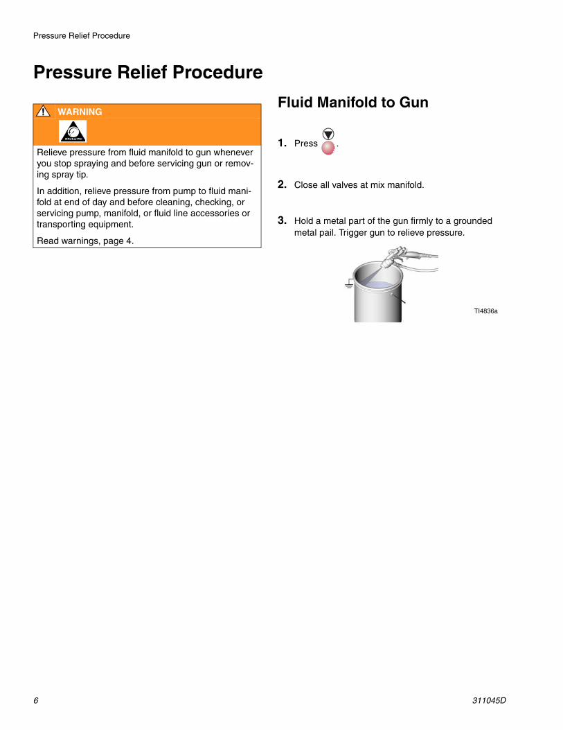
Relieve pressure from fluid manifold to gun whenever you stop spraying and before servicing gun or remov-ing spray tip.
In addition, relieve pressure from pump to fluid mani-fold at end of day and before cleaning, checking, or servicing pump, manifold, or fluid line accessories or transporting equipment.
Read warnings, page 4.
1. Press .
2. Close all valves at mix manifold.
3. Hold a metal part of the gun firmly to a grounded metal pail. Trigger gun to relieve pressure.
TI4836a
Pressure Relief Procedure
311045D 7
Pump to Fluid Manifold
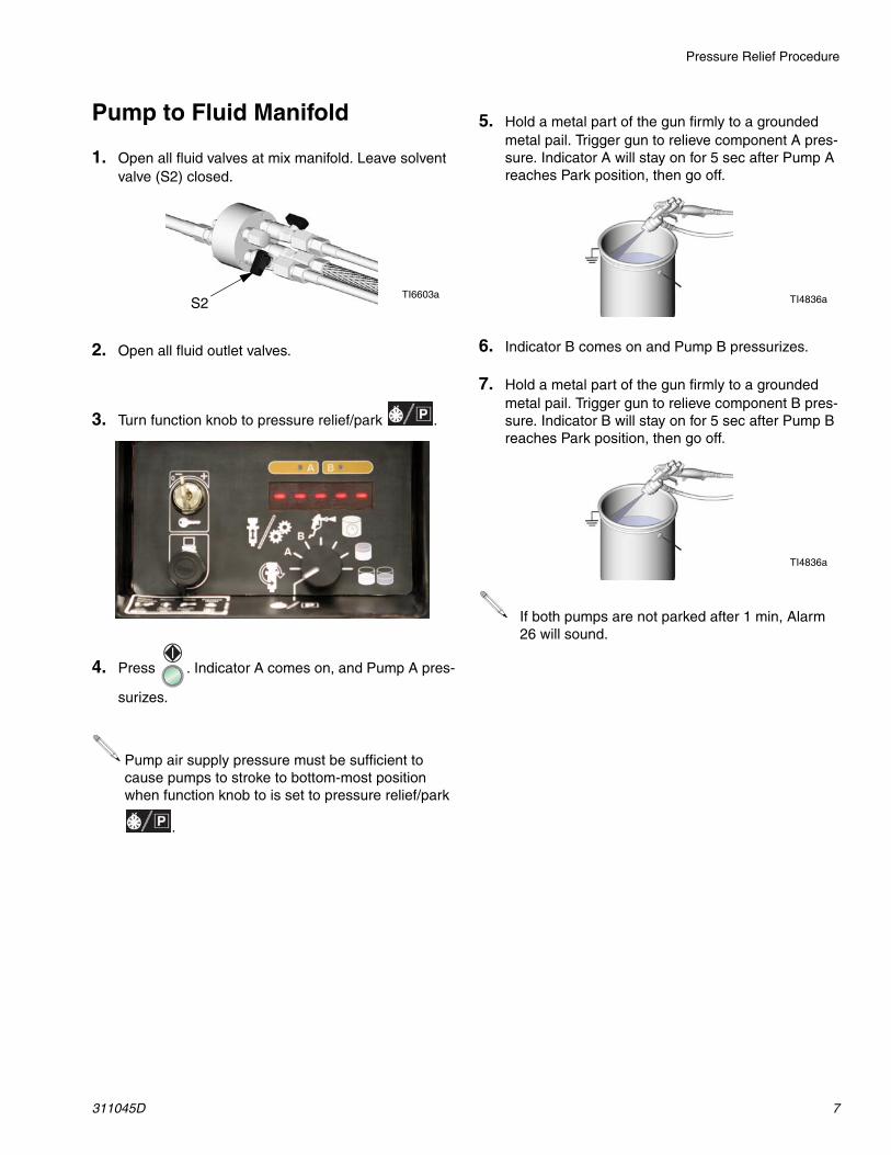
1. Open all fluid valves at mix manifold. Leave solvent valve (S2) closed.
2. Open all fluid outlet valves.
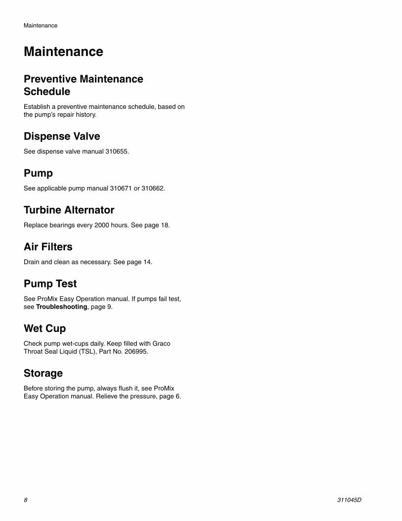
3. Turn function knob to pressure relief/park .
4. Press . Indicator A comes on, and Pump A pres-
surizes.
Pump air supply pressure must be sufficient to cause pumps to stroke to bottom-most position when function knob to is set to pressure relief/park
.
S2TI6603a
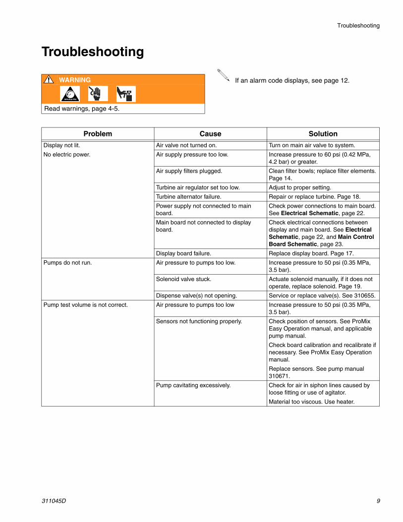
5. Hold a metal part of the gun firmly to a grounded metal pail. Trigger gun to relieve component A pres-sure. Indicator A will stay on for 5 sec after Pump A reaches Park position, then go off.
6. Indicator B comes on and Pump B pressurizes.
7. Hold a metal part of the gun firmly to a grounded metal pail. Trigger gun to relieve component B pres-sure. Indicator B will stay on for 5 sec after Pump B reaches Park position, then go off.
If both pumps are not parked after 1 min, Alarm 26 will sound.
TI4836a
TI4836a
Maintenance
8 311045D
Maintenance
Preventive Maintenance ScheduleEstablish a preventive maintenance schedule, based on the pump’s repair history.
Dispense ValveSee dispense valve manual 310655.
PumpSee applicable pump manual 310671 or 310662.
Turbine AlternatorReplace bearings every 2000 hours. See page 18.
Air FiltersDrain and clean as necessary. See page 14.
Pump TestSee ProMix Easy Operation manual. If pumps fail test, see Troubleshooting, page 9.
Wet CupCheck pump wet-cups daily. Keep filled with Graco Throat Seal Liquid (TSL), Part No. 206995.
StorageBefore storing the pump, always flush it, see ProMix Easy Operation manual. Relieve the pressure, page 6.
Troubleshooting
311045D 9
Troubleshooting
WARNING
Read warnings, page 4-5.
If an alarm code displays, see page 12.
Problem Cause Solution
Display not lit.
No electric power.
Air valve not turned on. Turn on main air valve to system.
Air supply pressure too low. Increase pressure to 60 psi (0.42 MPa, 4.2 bar) or greater.
Air supply filters plugged. Clean filter bowls; replace filter elements. Page 14.
Turbine air regulator set too low. Adjust to proper setting.
Turbine alternator failure. Repair or replace turbine. Page 18.
Power supply not connected to main board.
Check power connections to main board. See Electrical Schematic, page 22.
Main board not connected to display board.
Check electrical connections between display and main board. See Electrical Schematic, page 22, and Main Control Board Schematic, page 23.
Display board failure. Replace display board. Page 17.
Pumps do not run. Air pressure to pumps too low. Increase pressure to 50 psi (0.35 MPa, 3.5 bar).
Solenoid valve stuck. Actuate solenoid manually, if it does not operate, replace solenoid. Page 19.
Dispense valve(s) not opening. Service or replace valve(s). See 310655.
Pump test volume is not correct. Air pressure to pumps too low Increase pressure to 50 psi (0.35 MPa, 3.5 bar).
Sensors not functioning properly. Check position of sensors. See ProMix Easy Operation manual, and applicable pump manual.
Check board calibration and recalibrate if necessary. See ProMix Easy Operation manual.
Replace sensors. See pump manual 310671.
Pump cavitating excessively. Check for air in siphon lines caused by loose fitting or use of agitator.
Material too viscous. Use heater.

Troubleshooting
10 311045D
Paint does not cure consistently. Ratio not set correctly. Check that correct ratio is set and set by volume. See ProMix Easy Operation manual.
Material not mixing correctly. Test pump. Page 8.
Make sure mixer is clean; flush as needed. See ProMix Easy Operation manual.
Pump not operating correctly. Observe whether pumps are loading and checking correctly, if not, clean and repair pump. See displacement pump manual 310662.
Poor spray pattern. Fluid pressure too low. Increase pump pressure.
Spray tip dirty or worn. Relieve pressure. Clean or replace tip. Follow gun manual instructions.
Fluid A or B filters plugged. Clean filters.
Mixer or hoses partially plugged or too restrictive.
Inspect parts for cured material. Clean or replace, or use larger hoses and mixer.
System runs erratically. Air filter(s) clogged. Replace elements. Clean. Replace element(s). See page 14.
Air supply hoses undersized. Replace hoses with appropriate size.
Air compressor undersized. Use larger air compressor.
Air supply pressure tank undersized. Use larger pressure tank.
Air supply relief valve opens. Turbine air regulator set too high. Lower setting to 23-25 psi (172-241 kPa, 1.7-2.4 bar).
Turbine alternator makes high-pitched whining noise.
Turbine bearings worn. (Setting turbine air regulator too high, wears bearings.)
Replace bearings. Page 18.
Display shows 88888 or unit reboots unexpectedly.
Turbine is not supplying enough power to board.
Increase turbine regulator setting to 23-25 psi (172-241 kPa, 1.7-2.4 bar).
Check turbine and electrical control exhaust air for restrictions.
Replace turbine bearings. Page 18.
ProMix Easy does not start when start button is pressed.
Faulty start switch or wire harness. Check start switch and wiring harness continuity; switch is normally open circuit. See Electrical Schematic, page 22.
Faulty stop switch or wiring harness. Check stop switch and wiring harness continuity; stop switch is normally closed circuit. See Electrical Schematic, page 22.
Bad I/O port on display board. Replace board. Page 17.
Bad I/O port on main board. Replace board. Page 16.
Dispense valves leaking. Loose or worn packings. Tighten packing nut. If leak continues, replace packings. See 310655.
Problem Cause Solution
Troubleshooting
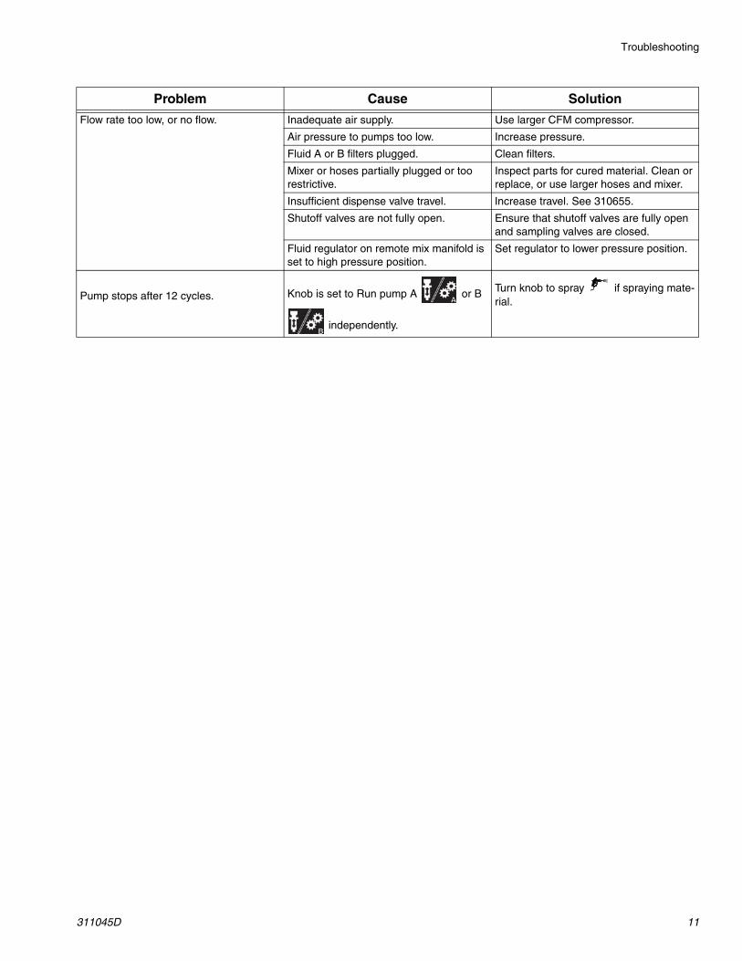
311045D 11
Flow rate too low, or no flow. Inadequate air supply. Use larger CFM compressor.
Air pressure to pumps too low. Increase pressure.
Fluid A or B filters plugged. Clean filters.
Mixer or hoses partially plugged or too restrictive.
Inspect parts for cured material. Clean or replace, or use larger hoses and mixer.
Insufficient dispense valve travel. Increase travel. See 310655.
Shutoff valves are not fully open. Ensure that shutoff valves are fully open and sampling valves are closed.
Fluid regulator on remote mix manifold is set to high pressure position.
Set regulator to lower pressure position.
Pump stops after 12 cycles. Knob is set to Run pump A or B
independently.
Turn knob to spray if spraying mate-rial.
Problem Cause Solution

Alarms
12 311045D
Alarms* Indicates error where audible alarm sounds once briefly. ** Indicates error where audible alarm sound pulses.
Code Alarm Active Problem Cause
Startup Errors01 Sensor Error A* Always No signal from pump A
sensorLoose cable, failed sensor or cable, failed magnet assembly
02 Sensor Error B* Always No signal from pump B sensor
Loose cable, failed sensor or cable, failed magnet assembly
03 Communication Error* Always Loss of communication between main and dis-play boards
Loose cable, failed board
Operating Errors04 not used
05 not used
06 Pump Error A** SprayTest
Batch
Pump does not stall after top change over
Pump cavitating exces-sively
Intake valve leak
Air in siphon lines caused by loose fitting or use of agitator
Empty fluid supply
07 Pump Error B**
08 Sensor Code Error Always Sensor values reverted to default
Sensor value data corrupt; board needs replacement and /or recalibration
09 not used
10 not used
11 Sensor Reading Low A* SprayTest
Batch
Pump stroke travels beyond sensor range at top change over
Sensor or bracket loose
Sensor magnet dirty12 Sensor Reading Low B*
13 Sensor Reading High A* SprayTest
Batch
Pump stroke travels beyond sensor range at bottom change over
Sensor or bracket loose
Sensor magnet dirty14 Sensor Reading High B*
21 Pot Life Error Spray first, then Always
Pot life timer timed out Not enough material sprayed after last reset
Alarms
311045D 13
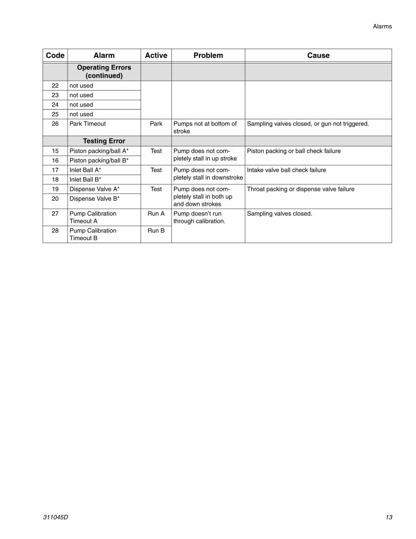
Operating Errors (continued)
22 not used
23 not used
24 not used
25 not used
26 Park Timeout Park Pumps not at bottom of stroke
Sampling valves closed, or gun not triggered.
Testing Error15 Piston packing/ball A* Test Pump does not com-
pletely stall in up strokePiston packing or ball check failure
16 Piston packing/ball B*
17 Inlet Ball A* Test Pump does not com-pletely stall in downstroke
Intake valve ball check failure
18 Inlet Ball B*
19 Dispense Valve A* Test Pump does not com-pletely stall in both up and down strokes
Throat packing or dispense valve failure
20 Dispense Valve B*
27 Pump Calibration Timeout A
Run A Pump doesn’t run through calibration.
Sampling valves closed.
28 Pump Calibration Timeout B
Run B
Code Alarm Active Problem Cause

Repair
14 311045D
RepairFlush before repairing equipment, if possible. See Pro-Mix Easy Operation manual.
Follow Pressure Relief Procedure, page 6, if service time may exceed pot life time, before servicing fluid components, and before transporting equipment to a service area.
Replacing Air Filter ElementThere are 2 air filters on the unit: the 5 micron air mani-fold filter (7) and 40 micron pump air filter (9). Replace element as needed. Order 15D909 5 micron filter and 15D890 40 micron filter.
1. Close main air shutoff valve on air supply line and on unit.
2. Remove left side plate (21).
3. Unlock filter bowl guard and remove.
4. Unscrew filter bowl.
5. Remove and replace element.
6. Screw filter bowl on securely.
7. Reassemble.
WARNING
Read warnings, page 4.
WARNING
Removing the bowl of a pressurized air filter could cause serious injury. Do not service air filter until air line is depressurized.
Repair
311045D 15
User Interface
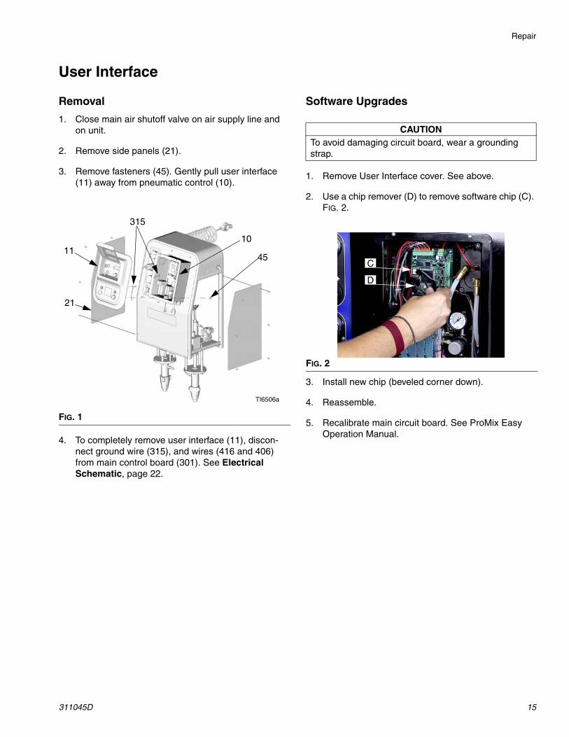
Removal
1. Close main air shutoff valve on air supply line and on unit.
2. Remove side panels (21).
3. Remove fasteners (45). Gently pull user interface (11) away from pneumatic control (10).
4. To completely remove user interface (11), discon-nect ground wire (315), and wires (416 and 406) from main control board (301). See Electrical Schematic, page 22.
Software Upgrades
1. Remove User Interface cover. See above.
2. Use a chip remover (D) to remove software chip (C). FIG. 2.
3. Install new chip (beveled corner down).
4. Reassemble.
5. Recalibrate main circuit board. See ProMix Easy Operation Manual.
FIG. 1
45
1011
315
TI6506a
21
CAUTIONTo avoid damaging circuit board, wear a grounding strap.
FIG. 2
C
D
Repair
16 311045D
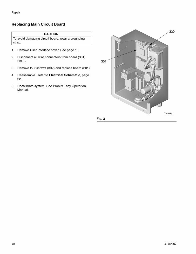
Replacing Main Circuit Board
1. Remove User Interface cover. See page 15.
2. Disconnect all wire connectors from board (301). FIG. 3.
3. Remove four screws (302) and replace board (301).
4. Reassemble. Refer to Electrical Schematic, page 22.
5. Recalibrate system. See ProMix Easy Operation Manual.
CAUTIONTo avoid damaging circuit board, wear a grounding strap.
FIG. 3
320
301
TI4561a
Repair
311045D 17
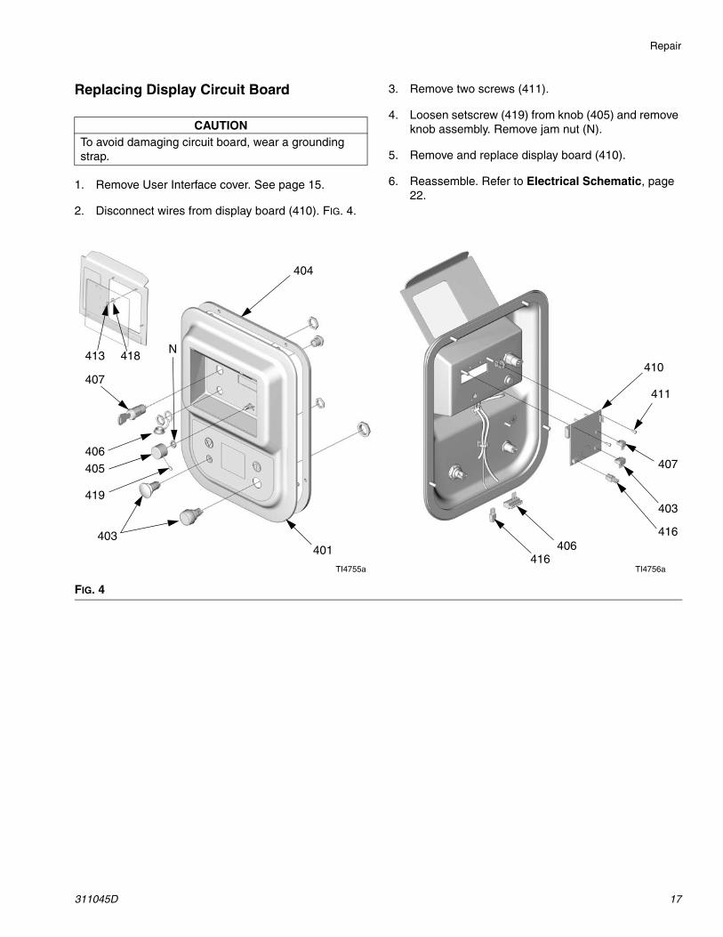
Replacing Display Circuit Board
1. Remove User Interface cover. See page 15.
2. Disconnect wires from display board (410). FIG. 4.
3. Remove two screws (411).
4. Loosen setscrew (419) from knob (405) and remove knob assembly. Remove jam nut (N).
5. Remove and replace display board (410).
6. Reassemble. Refer to Electrical Schematic, page 22.
CAUTIONTo avoid damaging circuit board, wear a grounding strap.
FIG. 4
416406
416
403
407
410
404
411
419
405
403
406
407
413 418
401
TI4755a TI4756a
N
Repair
18 311045D
Pneumatic Control
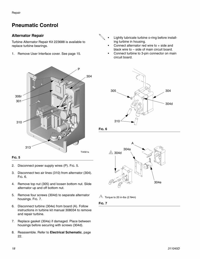
Alternator Repair
Turbine Alternator Repair Kit 223688 is available to replace turbine bearings.
1. Remove User Interface cover. See page 15.
2. Disconnect power supply wires (P). FIG. 5.
3. Disconnect two air lines (310) from alternator (304). FIG. 6.
4. Remove top nut (305) and loosen bottom nut. Slide alternator up and off bottom nut.
5. Remove four screws (304d) to separate alternator housings. FIG. 7.
6. Disconnect turbine (304e) from board (A). Follow instructions in turbine kit manual 308034 to remove and repair turbine.
7. Replace gasket (304a) if damaged. Place between housings before securing with screws (304d).
8. Reassemble. Refer to Electrical Schematic, page 22.
FIG. 5
P
301
TI4561a
306r
310
304
313
• Lightly lubricate turbine o-ring before install-ing turbine in housing.
• Connect alternator red wire to + side and black wire to – side of main circuit board.
• Connect turbine to 3-pin connector on main circuit board.
FIG. 6
FIG. 7
305
310
304
304d
304d
304e
A
304a
Torque to 20 in-lbs (2 N•m)1
1
Repair
311045D 19
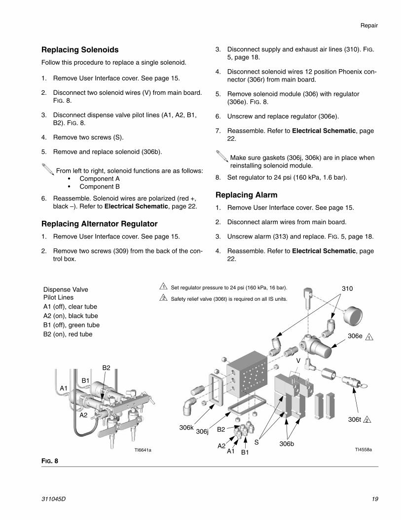
Replacing Solenoids
Follow this procedure to replace a single solenoid.
1. Remove User Interface cover. See page 15.
2. Disconnect two solenoid wires (V) from main board. FIG. 8.
3. Disconnect dispense valve pilot lines (A1, A2, B1, B2). FIG. 8.
4. Remove two screws (S).
5. Remove and replace solenoid (306b).
6. Reassemble. Solenoid wires are polarized (red +, black –). Refer to Electrical Schematic, page 22.
Replacing Alternator Regulator
1. Remove User Interface cover. See page 15.
2. Remove two screws (309) from the back of the con-trol box.
3. Disconnect supply and exhaust air lines (310). FIG. 5, page 18.
4. Disconnect solenoid wires 12 position Phoenix con-nector (306r) from main board.
5. Remove solenoid module (306) with regulator (306e). FIG. 8.
6. Unscrew and replace regulator (306e).
7. Reassemble. Refer to Electrical Schematic, page 22.
8. Set regulator to 24 psi (160 kPa, 1.6 bar).
Replacing Alarm
1. Remove User Interface cover. See page 15.
2. Disconnect alarm wires from main board.
3. Unscrew alarm (313) and replace. FIG. 5, page 18.
4. Reassemble. Refer to Electrical Schematic, page 22.
From left to right, solenoid functions are as follows:• Component A• Component B
Make sure gaskets (306j, 306k) are in place when reinstalling solenoid module.
FIG. 8
TI4558a
V
310
S
Set regulator pressure to 24 psi (160 kPa, 16 bar).
Safety relief valve (306t) is required on all IS units.
1
2
1306e
306b
306j306k
TI6641a
Dispense Valve Pilot LinesA1 (off), clear tubeA2 (on), black tubeB1 (off), green tubeB2 (on), red tube
2306t
A1
A2
B1
B2
A1 B1A2
B2
Repair
20 311045D
Dispense Valve AssemblySee the Parts drawing for your model.
1. Follow Pressure Relief Procedure, page 6.
2. Label all air and fluid lines, and disconnect from fit-tings on manifold assembly.
3. Remove fasteners.
4. Remove mix manifold (2).
5. To repair mix manifold, see manual 310654. To repair dispense valves, see manual 310655.
6. Reassemble.
Pump AssemblySee the Parts drawing for your model.
1. Follow Pressure Relief Procedure, page 6.
2. Remove side plates (21).
3. Remove wire harnesses from sensor and solenoids. Refer to Electrical Schematic, page 22.
4. Disconnect fluid inlet and outlet lines from pump lower. Disconnect air supply from pump.
5. Label all tubing and disconnect from fittings on pump assembly.
6. Remove mounting hardware and slide pump out of frame.
7. Repair as instructed in pump manuals 310671, 310672, or 310662.
8. Reassemble.
WARNING
Read warnings, page 4.
WARNING
Read warnings, page 4.
Repair
311045D 21
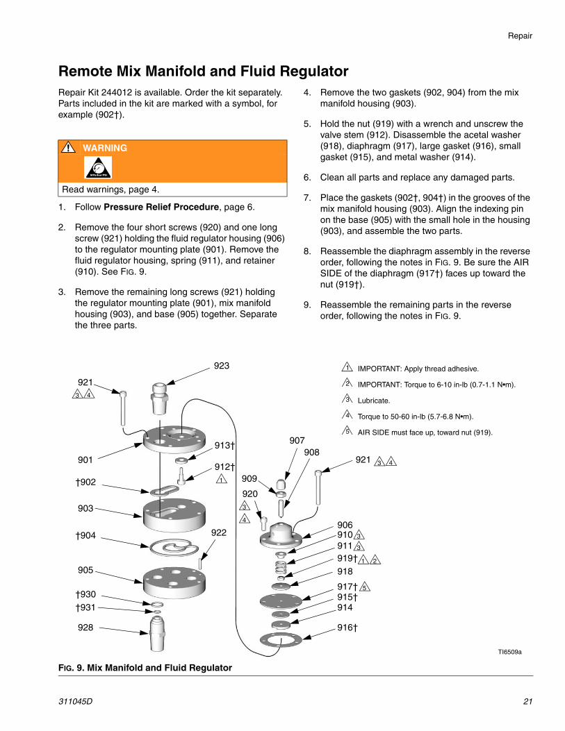
Remote Mix Manifold and Fluid RegulatorRepair Kit 244012 is available. Order the kit separately. Parts included in the kit are marked with a symbol, for example (902†).
1. Follow Pressure Relief Procedure, page 6.
2. Remove the four short screws (920) and one long screw (921) holding the fluid regulator housing (906) to the regulator mounting plate (901). Remove the fluid regulator housing, spring (911), and retainer (910). See FIG. 9.
3. Remove the remaining long screws (921) holding the regulator mounting plate (901), mix manifold housing (903), and base (905) together. Separate the three parts.
4. Remove the two gaskets (902, 904) from the mix manifold housing (903).
5. Hold the nut (919) with a wrench and unscrew the valve stem (912). Disassemble the acetal washer (918), diaphragm (917), large gasket (916), small gasket (915), and metal washer (914).
6. Clean all parts and replace any damaged parts.
7. Place the gaskets (902†, 904†) in the grooves of the mix manifold housing (903). Align the indexing pin on the base (905) with the small hole in the housing (903), and assemble the two parts.
8. Reassemble the diaphragm assembly in the reverse order, following the notes in FIG. 9. Be sure the AIR SIDE of the diaphragm (917†) faces up toward the nut (919†).
9. Reassemble the remaining parts in the reverse order, following the notes in FIG. 9.
WARNING
Read warnings, page 4.
FIG. 9. Mix Manifold and Fluid Regulator
IMPORTANT: Apply thread adhesive.
IMPORTANT: Torque to 6-10 in-lb (0.7-1.1 N•m).
Lubricate.
Torque to 50-60 in-lb (5.7-6.8 N•m).
AIR SIDE must face up, toward nut (919).
1
2
3
4
5
1
2
3 4
5
TI6509a
901
†902
903
†904
905
906
907908
909
910911
912†
913†
914915†
916†
917†
918919†
920
921
922
923
928
†930†931
921 3 4
3
4
3
3
1
Electrical Schematic
22 311045D
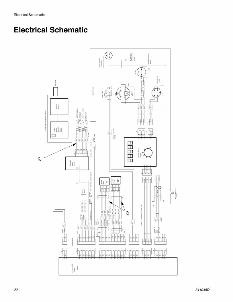
Electrical Schematic
RE
D
OR
AN
GE
OR
AN
GE
RE
D
+-
A4
3
72
2
41
181512963129631
BLA
CK
WH
ITE
RE
D
SH
IELD
BLU
E
WH
ITE
_W/B
LUE
WH
ITE
_W/O
RA
NG
E
GR
EE
N
WH
ITE
_W/G
RN
BLU
E
WH
ITE
_W/B
LUE
WH
ITE
_W/O
RA
NG
E
GR
EE
N
WH
ITE
_W/G
RN
SH
IELD
+
RE
D
41
3
BLA
CK
RE
D
RE
D
GR
EE
N
BLA
CK
BR
OW
N
GR
EE
N
BLA
CK
WH
ITE
B3
TX
1
GN
D
2
1
1 2 3 4 5 6
J1
52 63
1713107 1411851107 28 1141 2
JUM
PE
R (
15V
)2B
LAC
K
52 63
SE
NS
OR
2436
78
1 2
J3
CO
MM
PO
RT
AS
SY
15A
850
WH
ITE
81
1 2LIG
HT
RX
2 3
FR
ON
T P
AN
EL
1
ST
OP
181512
963
16 17
4 5 8
11
7
13 14
1 2
J4
1 2 3 4 5 6 8 910 11
7
12
J5
16453
+
SE
NS
OR
2436
78
PO
WE
R
SU
PP
LY
BA
RR
IER
BO
AR
D
53 41 2
J2
PO
WE
R
SU
PP
LY
CO
M P
OR
T
RS
232
CO
NN
EC
TO
R
STA
RT
KE
Y S
WIT
CH
M
OM
.
1 2 3 4 5 6 7
J21 2 3 4 5 6 7
BLA
CK
RE
D
SH
IELD
BLA
CK
RE
D
RE
D
2483
49
15V
DC
62
62
ALA
RM
CO
MA
LAR
M +
3421
1
GN
D
AIR
INP
UT
CA
BLE
# 1
5D60
7 (
X2)
BLA
CK
BLA
CK
BLA
CK
CO
M
1 2 3 4 5 6
J1
34
3
15
15
ALA
RM
AS
SY
15A
849
15 23
GN
D
DIS
PLA
Y B
OA
RD
245
706
4FLU
ID
VA
LVE
S
2
KE
Y S
WIT
CH
AS
SY
15A
852
CA
BLE
# 1
5A85
4 (M
AIN
TO
DIS
PLA
Y)
(OP
PO
SIT
E S
IDE
OF
SO
LDE
R C
UP
S)
-S
OLE
NO
ID V
ALV
E B
STA
RT
/ST
OP
SW
ITC
H A
SS
Y
15A
851
CO
M P
OR
T P
IN L
OC
ATIO
NS
F
RO
NT
SID
E V
IEW
-S
OLE
NO
ID V
ALV
E A
PO
WE
R S
UP
PLY
AS
SE
MB
LY 2
4522
3
1 2 3
J6
MA
IN C
ON
TR
OL
B
OA
RD
10
SO
LEN
OID
BO
AR
D
15C
735
P S GR
ED
63 7 841 2 5
P4
+
+
BLA
CK
RE
D
RE
D
BLA
CK
-M
OT
OR
B U
P
-M
OT
OR
B D
OW
N
+
+
BLA
CK
RE
D
RE
D
BLA
CK
-M
OT
OR
A U
P
-M
OT
OR
A D
OW
N
1 2 3 4
12V
DC
BLA
CK
WH
ITE
RE
D
WH
ITE
SIG
NA
L A
CO
M12
VD
CS
IGN
AL
B
ME
TE
R A
ME
TE
R B
2397
90
+ -O
PT.
SO
LEN
OID
, RE
CIR
C. 5
5218
0C
AB
LE #
114
213
5 6 7
J81 2 3 4 5 6 7
88
OR
AN
GE
BLA
CK
12V
DC
AIR
FLO
W S
WIT
CH
1
1915
92346
28
15D
794
"A" "B"
26
27
Main Control Board Schematic
311045D 23
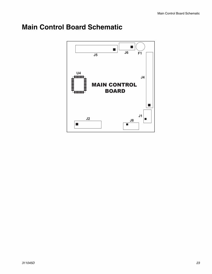
Main Control Board Schematic
MAIN CONTROL BOARD
J5J6 F1
J4
J1
J8J2
U4

Parts
24 311045D
Parts
Part No. 249322 System, Series A
101
146
TI6629a
148
103
149
148
See Detail below.
126
TI6385a
107 108 134
141
110
TI6504a
Solvent Pump Detail
139
111
112
113
133
122
132
130
111
131
129
131
111
131
111
135
123
162

Parts
311045D 25
Part No. 249322 System, Series A
† These parts are shown on page 26.
Ref. No. Part No. Description Qty.101 249302 PROPORTIONER; see page 26 1103 249387 DISPENSE VALVE ASSEMBLY;
see page 341
107 156589 UNION, adapter, 90°; 3/4 npt(f) x 3/4 npsm(f)
2
108 100505 BUSHING, pipe; 3/4 npt(m) x 3/8 npt(f)
2
110 15D986 PLATE, rear 1111 116698 VALVE, ball; 1/4 npt(m) x 1/4
npt(f)4
112 113093 CONNECTOR, pipe; 1/4 npt (fbe) 1113 110249 ELBOW, 90°; 1/4 npt (mbe) 1122 159239 NIPPLE; 1/2 npt x 3/8 npt 1123 243832 HOSE, siphon, solvent pump 1126 248588 KIT, air regulator, gun; see
3107001
127 249386 HOSES/MIX MANIFOLD; see page 35
1
129 102959 CROSS, pipe; 1/4 npt(f) 1130 100840 ELBOW, street; 1/4 npt(m) x 1/4
npsm(f)3
131 162453 NIPPLE; 1/4 npt x 1/4 npsm 3132 165198 NIPPLE, reducing; 3/8 npt x 1/4
npt1
133 D32911 PUMP, double diaphragm, sol-vent; see 308553
1
134 162485 NIPPLE; 3/8 npt x 3/8 npsm 2135 243803 HOSE, fluid; 1/4 npsm (fbe); 1/4
in. (6 mm) ID; nylon; 3 ft (0.9 m)2
139 C19413 CONNECTOR; 1/4 npt(m) x 3/8 in. (10 mm) OD tube
1
141 119291 SCREW, self-tapping 10142† 206966 HOSE, fluid; 1/4 npsm (fbe);
PTFE; 1/4 in. (6 mm) ID; 18 in. (457 mm)
2
145† 119798 CONNECTOR, tee; 3/8 in. (10 mm) OD tube
1
146 113796 SCREW, cap, hex flanged hd; 1/4-20 x 3/4 in. (19 mm)
2
148 115942 NUT, hex, flange hd; 1/4-20 6149 100021 SCREW, cap, hex hd; 1/4-20 x 1
in. (25 mm)4
157 C12508 TUBE; nylon; 3/8 in. (10 mm) OD; see pages 28 and 29
4.5ft
158† 115841 ELBOW; 1/4 npt(m) x 3/8 in. (10 mm) OD tube
1
159† 104641 FITTING, bulkhead 1160† 113319 FITTING, air; 1/4 npt(m) x
3/8 in. (10 mm) OD tube1
161† C38211 ELBOW; 1/2 npt(m) x 3/8 in. (10 mm) OD tube fitting
1
162 116750 TUBE; nylon; 1/4 in. (6 mm) ID 2
Parts
26 311045D
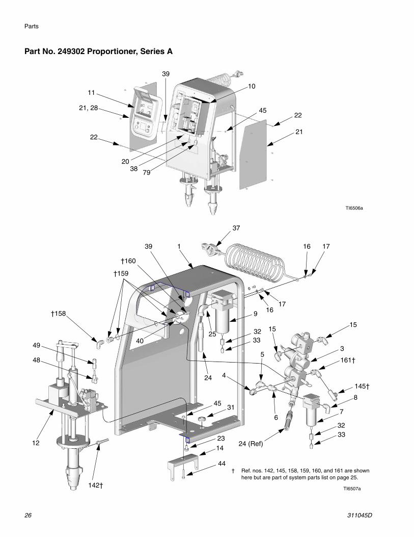
Part No. 249302 Proportioner, Series A
10
22
21
20
45
22
21, 28
11
TI6506a
38 79
39
TI6507a
37
1
17169
3233
1515
53
7
8
3233
24 (Ref)
6
4
25
24
31
2314
12
45
44
49
48
1716
† Ref. nos. 142, 145, 158, 159, 160, and 161 are shown here but are part of system parts list on page 25.
142†
161†
145†
40
39
†160
†159
†158
Parts
311045D 27
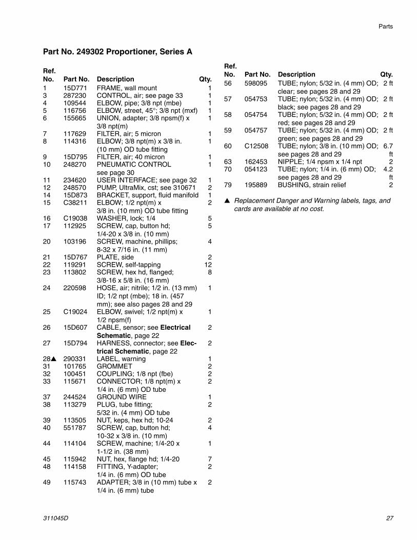
Part No. 249302 Proportioner, Series A
▲ Replacement Danger and Warning labels, tags, and cards are available at no cost.
Ref. No. Part No. Description Qty.1 15D771 FRAME, wall mount 13 287230 CONTROL, air; see page 33 14 109544 ELBOW, pipe; 3/8 npt (mbe) 15 116756 ELBOW, street, 45°; 3/8 npt (mxf) 16 155665 UNION, adapter; 3/8 npsm(f) x
3/8 npt(m)1
7 117629 FILTER, air; 5 micron 18 114316 ELBOW; 3/8 npt(m) x 3/8 in.
(10 mm) OD tube fitting1
9 15D795 FILTER, air; 40 micron 110 248270 PNEUMATIC CONTROL
see page 301
11 234620 USER INTERFACE; see page 32 112 248570 PUMP, UltraMix, cst; see 310671 214 15D873 BRACKET, support, fluid manifold 115 C38211 ELBOW; 1/2 npt(m) x
3/8 in. (10 mm) OD tube fitting2
16 C19038 WASHER, lock; 1/4 517 112925 SCREW, cap, button hd;
1/4-20 x 3/8 in. (10 mm)5
20 103196 SCREW, machine, phillips; 8-32 x 7/16 in. (11 mm)
4
21 15D767 PLATE, side 222 119291 SCREW, self-tapping 1223 113802 SCREW, hex hd, flanged;
3/8-16 x 5/8 in. (16 mm)8
24 220598 HOSE, air; nitrile; 1/2 in. (13 mm) ID; 1/2 npt (mbe); 18 in. (457 mm); see also pages 28 and 29
1
25 C19024 ELBOW, swivel; 1/2 npt(m) x 1/2 npsm(f)
1
26 15D607 CABLE, sensor; see Electrical Schematic, page 22
2
27 15D794 HARNESS, connector; see Elec-trical Schematic, page 22
2
28▲ 290331 LABEL, warning 131 101765 GROMMET 232 100451 COUPLING; 1/8 npt (fbe) 233 115671 CONNECTOR; 1/8 npt(m) x
1/4 in. (6 mm) OD tube2
37 244524 GROUND WIRE 138 113279 PLUG, tube fitting;
5/32 in. (4 mm) OD tube2
39 113505 NUT, keps, hex hd; 10-24 240 551787 SCREW, cap, button hd;
10-32 x 3/8 in. (10 mm)4
44 114104 SCREW, machine; 1/4-20 x 1-1/2 in. (38 mm)
1
45 115942 NUT, hex, flange hd; 1/4-20 748 114158 FITTING, Y-adapter;
1/4 in. (6 mm) OD tube2
49 115743 ADAPTER; 3/8 in (10 mm) tube x 1/4 in. (6 mm) tube
2
56 598095 TUBE; nylon; 5/32 in. (4 mm) OD; clear; see pages 28 and 29
2 ft
57 054753 TUBE; nylon; 5/32 in. (4 mm) OD; black; see pages 28 and 29
2 ft
58 054754 TUBE; nylon; 5/32 in. (4 mm) OD; red; see pages 28 and 29
2 ft
59 054757 TUBE; nylon; 5/32 in. (4 mm) OD; green; see pages 28 and 29
2 ft
60 C12508 TUBE; nylon; 3/8 in. (10 mm) OD; see pages 28 and 29
6.7ft
63 162453 NIPPLE; 1/4 npsm x 1/4 npt 270 054123 TUBE; nylon; 1/4 in. (6 mm) OD;
see pages 28 and 294.2
ft79 195889 BUSHING, strain relief 2
Ref. No. Part No. Description Qty.
Parts
28 311045D
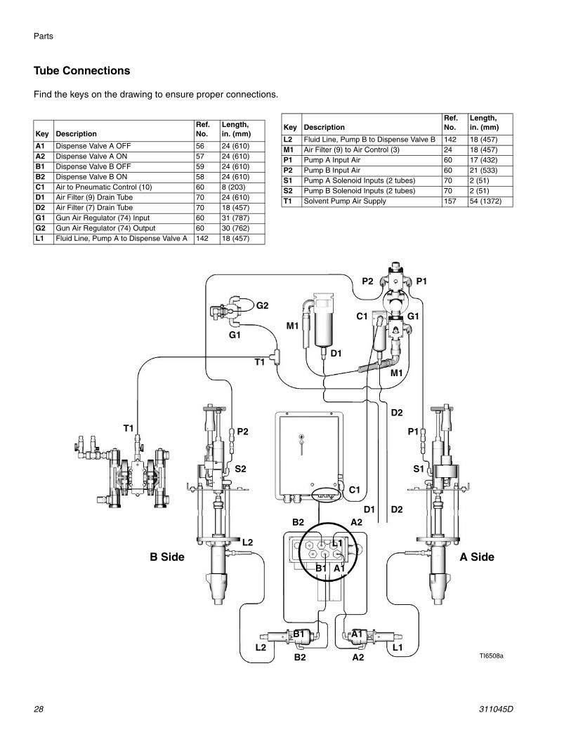
Tube Connections
Find the keys on the drawing to ensure proper connections.
Key DescriptionRef. No.
Length, in. (mm)
A1 Dispense Valve A OFF 56 24 (610)A2 Dispense Valve A ON 57 24 (610)B1 Dispense Valve B OFF 59 24 (610)B2 Dispense Valve B ON 58 24 (610)C1 Air to Pneumatic Control (10) 60 8 (203)D1 Air Filter (9) Drain Tube 70 24 (610)D2 Air Filter (7) Drain Tube 70 18 (457)G1 Gun Air Regulator (74) Input 60 31 (787)G2 Gun Air Regulator (74) Output 60 30 (762)L1 Fluid Line, Pump A to Dispense Valve A 142 18 (457)
L2 Fluid Line, Pump B to Dispense Valve B 142 18 (457)M1 Air Filter (9) to Air Control (3) 24 18 (457)P1 Pump A Input Air 60 17 (432)P2 Pump B Input Air 60 21 (533)S1 Pump A Solenoid Inputs (2 tubes) 70 2 (51)S2 Pump B Solenoid Inputs (2 tubes) 70 2 (51)T1 Solvent Pump Air Supply 157 54 (1372)
Key DescriptionRef. No.
Length, in. (mm)
TI6508a
C1
D1 D2
G1
L1
L2
M1
P1
P2
S1S2
A SideB Side
A2B2
C1
D1
D2
G1
G2
L1
L2
M1
P1
P2
A1
A2B2
B1
B1 A1
T1
T1
Parts
311045D 29
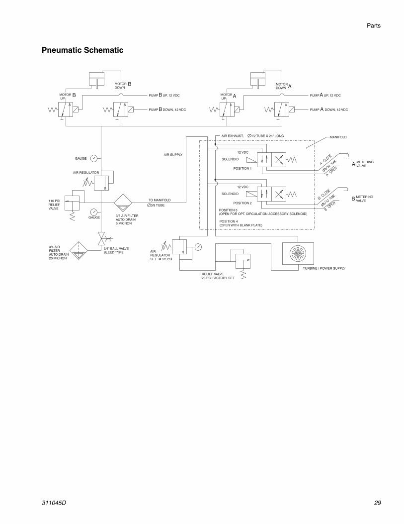
Pneumatic Schematic
MOTORDOWN A
MOTOR UP A PUMP UP, 12 VDC
PUMP DOWN, 12 VDC
GAUGE
AIR REGULATOR
3/8 AIR FILTERAUTO DRAIN5 MICRON
3/4" BALL VALVEBLEED TYPE
110 PSIRELIEFVALVE
TO MANIFOLD
SOLENOID
12 VDC
METERINGVALVE
B
A
METERINGVALVE
SOLENOID
12 VDC
AIRREGULATORSET @ 22 PSI
TURBINE / POWER SUPPLY
AIR SUPPLY
MANIFOLD
RELIEF VALVE26 PSI FACTORY SET
3/4 AIRFILTERAUTO DRAIN20 MICRON
A
A
GAUGE
3/8 TUBE
POSITION 1
POSITION 2
AIR EXHAUST, 1/2 TUBE X 24" LONG
MOTORDOWN
B
MOTOR UP
B PUMP UP, 12 VDC
PUMP DOWN, 12 VDC
B
B
POSITION 3(OPEN FOR OPT. CIRCULATION ACCESSORY SOLENOID)
POSITION 4(OPEN WITH BLANK PLATE)
Parts
30 311045D
248270 Intrinsically Safe Pneumatic Control
320
302, 321
314
304
310
308313
322
306
315
311301
323
307
306h
306e
306m306s
306t
306u306b
306n
306c306j306k
306n306f
306p
306n
306a
306f 306d
306g306f
TI4561a
TI4558a
304d
304e
304a
Solenoid Module (306) Detail
Alternator Module (304) Detail
304c
304b
Parts
311045D 31
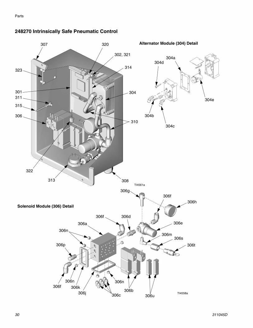
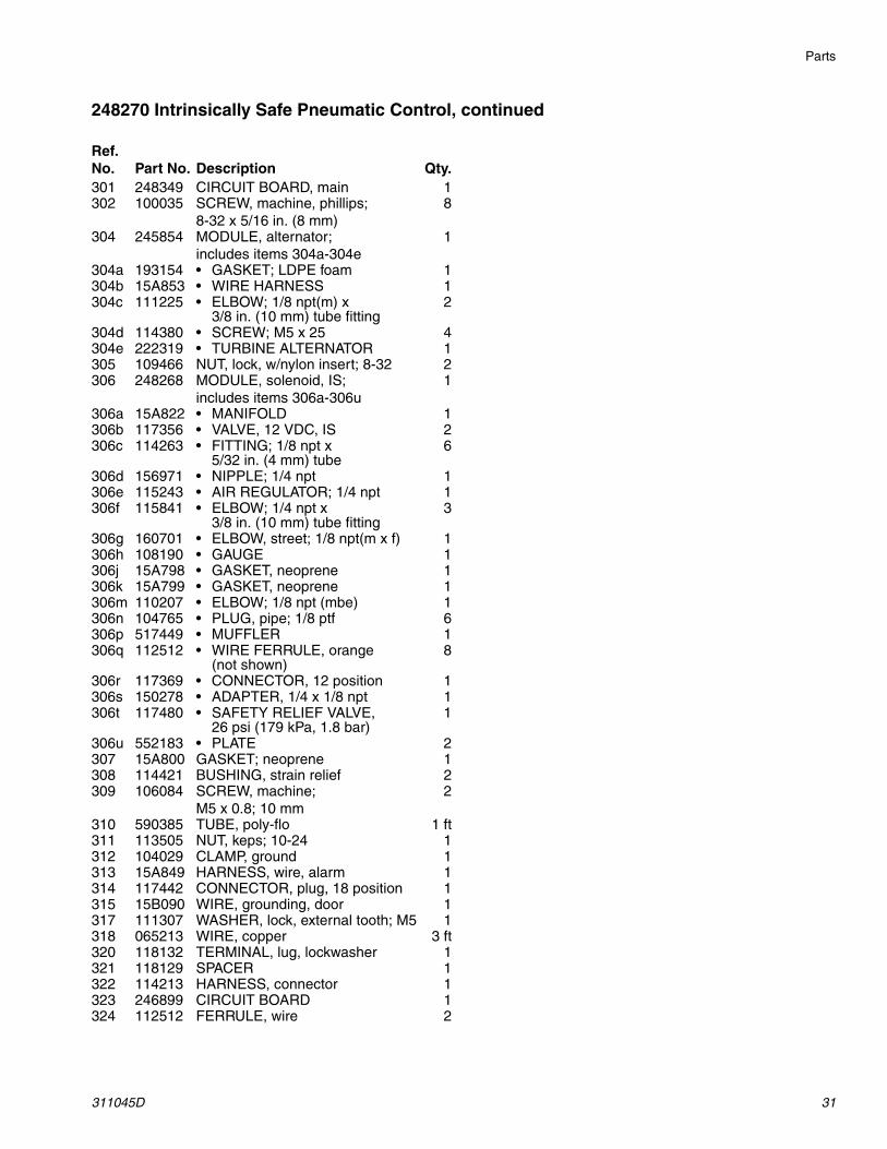
248270 Intrinsically Safe Pneumatic Control, continued
Ref. No. Part No. Description Qty.301 248349 CIRCUIT BOARD, main 1302 100035 SCREW, machine, phillips;
8-32 x 5/16 in. (8 mm)8
304 245854 MODULE, alternator; includes items 304a-304e
1
304a 193154 • GASKET; LDPE foam 1304b 15A853 • WIRE HARNESS 1304c 111225 • ELBOW; 1/8 npt(m) x
3/8 in. (10 mm) tube fitting2
304d 114380 • SCREW; M5 x 25 4304e 222319 • TURBINE ALTERNATOR 1305 109466 NUT, lock, w/nylon insert; 8-32 2306 248268 MODULE, solenoid, IS;
includes items 306a-306u1
306a 15A822 • MANIFOLD 1306b 117356 • VALVE, 12 VDC, IS 2306c 114263 • FITTING; 1/8 npt x
5/32 in. (4 mm) tube6
306d 156971 • NIPPLE; 1/4 npt 1306e 115243 • AIR REGULATOR; 1/4 npt 1306f 115841 • ELBOW; 1/4 npt x
3/8 in. (10 mm) tube fitting3
306g 160701 • ELBOW, street; 1/8 npt(m x f) 1306h 108190 • GAUGE 1306j 15A798 • GASKET, neoprene 1306k 15A799 • GASKET, neoprene 1306m 110207 • ELBOW; 1/8 npt (mbe) 1306n 104765 • PLUG, pipe; 1/8 ptf 6306p 517449 • MUFFLER 1306q 112512 • WIRE FERRULE, orange
(not shown)8
306r 117369 • CONNECTOR, 12 position 1306s 150278 • ADAPTER, 1/4 x 1/8 npt 1306t 117480 • SAFETY RELIEF VALVE,
26 psi (179 kPa, 1.8 bar)1
306u 552183 • PLATE 2307 15A800 GASKET; neoprene 1308 114421 BUSHING, strain relief 2309 106084 SCREW, machine;
M5 x 0.8; 10 mm2
310 590385 TUBE, poly-flo 1 ft311 113505 NUT, keps; 10-24 1312 104029 CLAMP, ground 1313 15A849 HARNESS, wire, alarm 1314 117442 CONNECTOR, plug, 18 position 1315 15B090 WIRE, grounding, door 1317 111307 WASHER, lock, external tooth; M5 1318 065213 WIRE, copper 3 ft320 118132 TERMINAL, lug, lockwasher 1321 118129 SPACER 1322 114213 HARNESS, connector 1323 246899 CIRCUIT BOARD 1324 112512 FERRULE, wire 2

Parts
32 311045D
234620 User Interface
Ref. No. Part No. Description Qty.401 15B062 DISPLAY 1403 15A851 HARNESS, wire 1404 15A801 GASKET; neoprene 1405 15D853 KNOB, control 1406 15A850 HARNESS, wire 1407 15A852 HARNESS, wire, switch 1408 15D796 LABEL, control, upper 1409 15D798 LABEL, control, lower 1410 245706 CIRCUIT BOARD, display;
includes jam nut (N)1
411 112546 SCREW, machine; 4-40 x 3/8 in. (10 mm)
2
412 15A856 PANEL, display 1413 C27076 NUT, lock, w/nylon insert; 4-40 4414 111907 MOUNT, tie wrap 3416 15A854 HARNESS, wire, display 1418 188438 WASHER; 0.120 in. 4419 101366 SCREW, set; socket hd;
10-24 x 5/16 (8 mm)1
Ref. No. Part No. Description Qty.
416406
416
403
407
410
404
411
419
405
403
406
407
413 418
401
TI4755a TI4756a
409
408
N
Parts
311045D 33
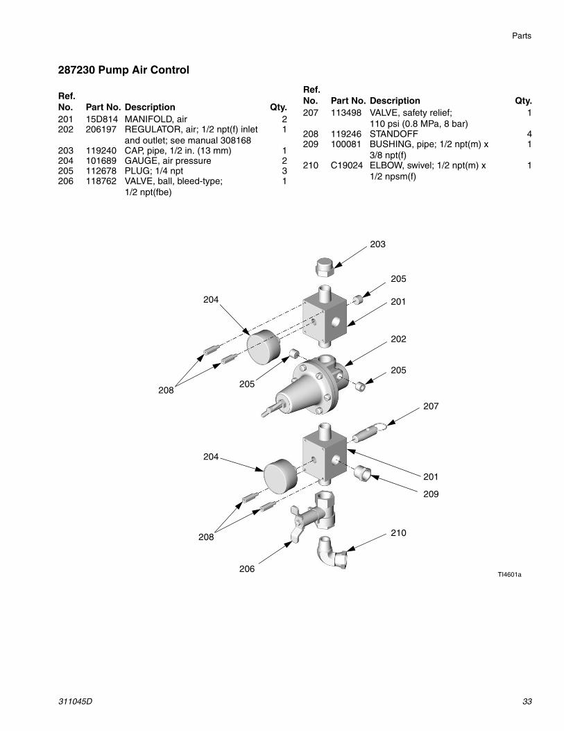
287230 Pump Air Control
Ref. No. Part No. Description Qty.201 15D814 MANIFOLD, air 2202 206197 REGULATOR, air; 1/2 npt(f) inlet
and outlet; see manual 3081681
203 119240 CAP, pipe, 1/2 in. (13 mm) 1204 101689 GAUGE, air pressure 2205 112678 PLUG; 1/4 npt 3206 118762 VALVE, ball, bleed-type;
1/2 npt(fbe)1
207 113498 VALVE, safety relief; 110 psi (0.8 MPa, 8 bar)
1
208 119246 STANDOFF 4209 100081 BUSHING, pipe; 1/2 npt(m) x
3/8 npt(f)1
210 C19024 ELBOW, swivel; 1/2 npt(m) x 1/2 npsm(f)
1
Ref. No. Part No. Description Qty.
203
205
201
202
205
207
201
209
210
206
208
204
205208
204
TI4601a
Parts
34 311045D
249387 Dispense Valve Assembly
TI6552a
701
710
710
703
707
710
702
713
712704
708
709, 707, 710
712704
702
711
717
717
702703
714
714
709
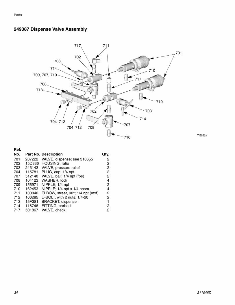
Ref. No. Part No. Description Qty.701 287222 VALVE, dispense; see 310655 2702 15D336 HOUSING, ratio 2703 245143 VALVE, pressure relief 2704 115781 PLUG, cap; 1/4 npt 2707 512148 VALVE, ball; 1/4 npt (fbe) 2708 104123 WASHER, lock 4709 156971 NIPPLE; 1/4 npt 2710 162453 NIPPLE; 1/4 npt x 1/4 npsm 4711 100840 ELBOW, street, 90°; 1/4 npt (mxf) 2712 106285 U-BOLT, with 2 nuts; 1/4-20 2713 15F381 BRACKET, dispense 1714 116746 FITTING, barbed 2717 501867 VALVE, check 2
Parts
311045D 35
249386 Hose Bundle and Remote Mix Manifold
TI6409a
806e 803804 806d
806a
806b
806c
805
813
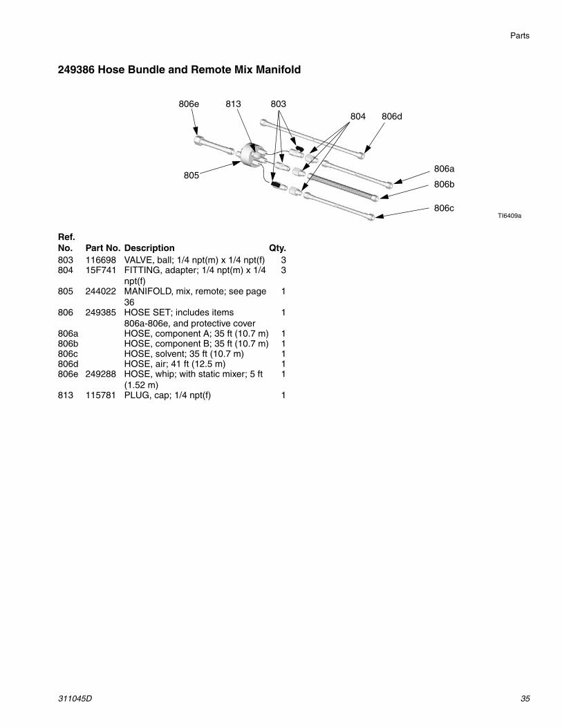
Ref. No. Part No. Description Qty.803 116698 VALVE, ball; 1/4 npt(m) x 1/4 npt(f) 3804 15F741 FITTING, adapter; 1/4 npt(m) x 1/4
npt(f)3
805 244022 MANIFOLD, mix, remote; see page 36
1
806 249385 HOSE SET; includes items 806a-806e, and protective cover
1
806a HOSE, component A; 35 ft (10.7 m) 1806b HOSE, component B; 35 ft (10.7 m) 1806c HOSE, solvent; 35 ft (10.7 m) 1806d HOSE, air; 41 ft (12.5 m) 1806e 249288 HOSE, whip; with static mixer; 5 ft
(1.52 m)1
813 115781 PLUG, cap; 1/4 npt(f) 1
Parts
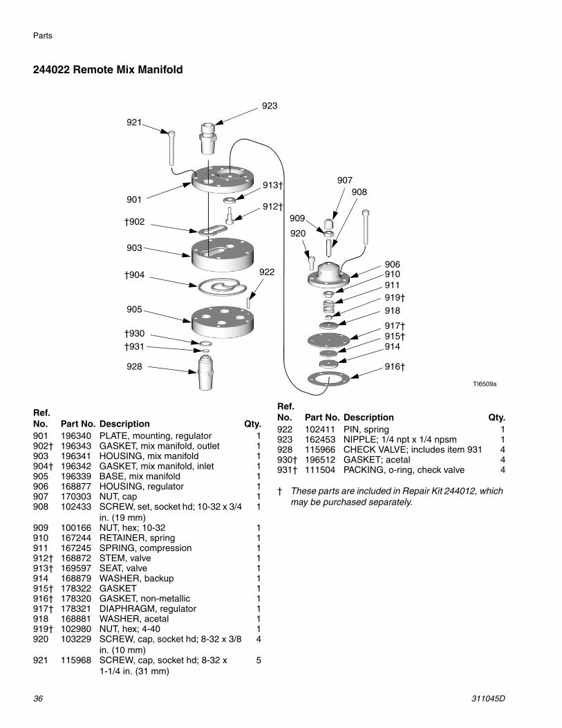
36 311045D
244022 Remote Mix Manifold
† These parts are included in Repair Kit 244012, which may be purchased separately.
TI6509a
901
†902
903
†904
905
906
907908
909
910911
912†
913†
914915†
916†
917†
918919†
920
921
922
923
928
†930†931
Ref. No. Part No. Description Qty.901 196340 PLATE, mounting, regulator 1902† 196343 GASKET, mix manifold, outlet 1903 196341 HOUSING, mix manifold 1904† 196342 GASKET, mix manifold, inlet 1905 196339 BASE, mix manifold 1906 168877 HOUSING, regulator 1907 170303 NUT, cap 1908 102433 SCREW, set, socket hd; 10-32 x 3/4
in. (19 mm)1
909 100166 NUT, hex; 10-32 1910 167244 RETAINER, spring 1911 167245 SPRING, compression 1912† 168872 STEM, valve 1913† 169597 SEAT, valve 1914 168879 WASHER, backup 1915† 178322 GASKET 1916† 178320 GASKET, non-metallic 1917† 178321 DIAPHRAGM, regulator 1918 168881 WASHER, acetal 1919† 102980 NUT, hex; 4-40 1920 103229 SCREW, cap, socket hd; 8-32 x 3/8
in. (10 mm)4
921 115968 SCREW, cap, socket hd; 8-32 x 1-1/4 in. (31 mm)
5
922 102411 PIN, spring 1923 162453 NIPPLE; 1/4 npt x 1/4 npsm 1928 115966 CHECK VALVE; includes item 931 4930† 196512 GASKET; acetal 4931† 111504 PACKING, o-ring, check valve 4
Ref. No. Part No. Description Qty.
Technical Data
311045D 37
Technical Data
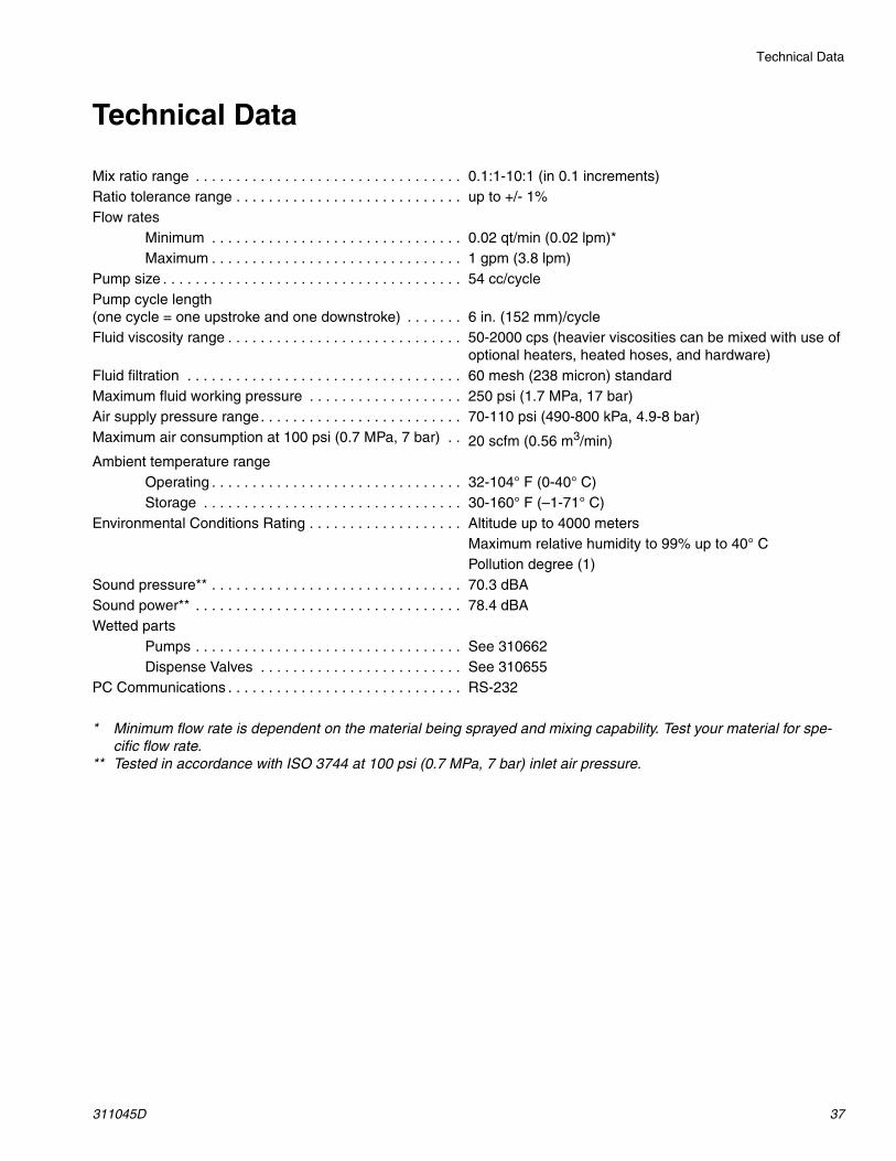
Mix ratio range . . . . . . . . . . . . . . . . . . . . . . . . . . . . . . . . . 0.1:1-10:1 (in 0.1 increments)Ratio tolerance range . . . . . . . . . . . . . . . . . . . . . . . . . . . . up to +/- 1%Flow rates
Minimum . . . . . . . . . . . . . . . . . . . . . . . . . . . . . . . 0.02 qt/min (0.02 lpm)*Maximum . . . . . . . . . . . . . . . . . . . . . . . . . . . . . . . 1 gpm (3.8 lpm)
Pump size . . . . . . . . . . . . . . . . . . . . . . . . . . . . . . . . . . . . . 54 cc/cyclePump cycle length (one cycle = one upstroke and one downstroke) . . . . . . . 6 in. (152 mm)/cycleFluid viscosity range . . . . . . . . . . . . . . . . . . . . . . . . . . . . . 50-2000 cps (heavier viscosities can be mixed with use of
optional heaters, heated hoses, and hardware)Fluid filtration . . . . . . . . . . . . . . . . . . . . . . . . . . . . . . . . . . 60 mesh (238 micron) standardMaximum fluid working pressure . . . . . . . . . . . . . . . . . . . 250 psi (1.7 MPa, 17 bar)Air supply pressure range. . . . . . . . . . . . . . . . . . . . . . . . . 70-110 psi (490-800 kPa, 4.9-8 bar)Maximum air consumption at 100 psi (0.7 MPa, 7 bar) . . 20 scfm (0.56 m3/min)Ambient temperature range
Operating . . . . . . . . . . . . . . . . . . . . . . . . . . . . . . . 32-104° F (0-40° C)Storage . . . . . . . . . . . . . . . . . . . . . . . . . . . . . . . . 30-160° F (–1-71° C)
Environmental Conditions Rating . . . . . . . . . . . . . . . . . . . Altitude up to 4000 metersMaximum relative humidity to 99% up to 40° CPollution degree (1)
Sound pressure** . . . . . . . . . . . . . . . . . . . . . . . . . . . . . . . 70.3 dBASound power** . . . . . . . . . . . . . . . . . . . . . . . . . . . . . . . . . 78.4 dBAWetted parts
Pumps . . . . . . . . . . . . . . . . . . . . . . . . . . . . . . . . . See 310662Dispense Valves . . . . . . . . . . . . . . . . . . . . . . . . . See 310655
PC Communications . . . . . . . . . . . . . . . . . . . . . . . . . . . . . RS-232
* Minimum flow rate is dependent on the material being sprayed and mixing capability. Test your material for spe-cific flow rate.
** Tested in accordance with ISO 3744 at 100 psi (0.7 MPa, 7 bar) inlet air pressure.
All written and visual data contained in this document reflects the latest product information available at the time of publication. Graco reserves the right to make changes at any time without notice.
Original instructions. This manual contains English. MM 311045
Graco Headquarters: MinneapolisInternational Offices: Belgium, China, Japan, Korea
GRACO INC. P.O. BOX 1441 MINNEAPOLIS, MN 55440-1441Copyright 2005, Graco Inc. is registered to ISO 9001
www.graco.comRevised 04/2010
Graco Standard WarrantyGraco warrants all equipment referenced in this document which is manufactured by Graco and bearing its name to be free from defects in material and workmanship on the date of sale to the original purchaser for use. With the exception of any special, extended, or limited warranty published by Graco, Graco will, for a period of twelve months from the date of sale, repair or replace any part of the equipment determined by Graco to be defective. This warranty applies only when the equipment is installed, operated and maintained in accordance with Graco’s written recommendations.
This warranty does not cover, and Graco shall not be liable for general wear and tear, or any malfunction, damage or wear caused by faulty installation, misapplication, abrasion, corrosion, inadequate or improper maintenance, negligence, accident, tampering, or substitution of non-Graco component parts. Nor shall Graco be liable for malfunction, damage or wear caused by the incompatibility of Graco equipment with structures, accessories, equipment or materials not supplied by Graco, or the improper design, manufacture, installation, operation or maintenance of structures, accessories, equipment or materials not supplied by Graco.
This warranty is conditioned upon the prepaid return of the equipment claimed to be defective to an authorized Graco distributor for verification of the claimed defect. If the claimed defect is verified, Graco will repair or replace free of charge any defective parts. The equipment will be returned to the original purchaser transportation prepaid. If inspection of the equipment does not disclose any defect in material or workmanship, repairs will be made at a reasonable charge, which charges may include the costs of parts, labor, and transportation.
THIS WARRANTY IS EXCLUSIVE, AND IS IN LIEU OF ANY OTHER WARRANTIES, EXPRESS OR IMPLIED, INCLUDING BUT NOT LIMITED TO WARRANTY OF MERCHANTABILITY OR WARRANTY OF FITNESS FOR A PARTICULAR PURPOSE.
Graco’s sole obligation and buyer’s sole remedy for any breach of warranty shall be as set forth above. The buyer agrees that no other remedy (including, but not limited to, incidental or consequential damages for lost profits, lost sales, injury to person or property, or any other incidental or consequential loss) shall be available. Any action for breach of warranty must be brought within two (2) years of the date of sale.
GRACO MAKES NO WARRANTY, AND DISCLAIMS ALL IMPLIED WARRANTIES OF MERCHANTABILITY AND FITNESS FOR A PARTICULAR PURPOSE, IN CONNECTION WITH ACCESSORIES, EQUIPMENT, MATERIALS OR COMPONENTS SOLD BUT NOT MANUFACTURED BY GRACO. These items sold, but not manufactured by Graco (such as electric motors, switches, hose, etc.), are subject to the warranty, if any, of their manufacturer. Graco will provide purchaser with reasonable assistance in making any claim for breach of these warranties.
In no event will Graco be liable for indirect, incidental, special or consequential damages resulting from Graco supplying equipment hereunder, or the furnishing, performance, or use of any products or other goods sold hereto, whether due to a breach of contract, breach of warranty, the negligence of Graco, or otherwise.
FOR GRACO CANADA CUSTOMERSThe Parties acknowledge that they have required that the present document, as well as all documents, notices and legal proceedings entered into, given or instituted pursuant hereto or relating directly or indirectly hereto, be drawn up in English. Les parties reconnaissent avoir convenu que la rédaction du présente document sera en Anglais, ainsi que tous documents, avis et procédures judiciaires exécutés, donnés ou intentés, à la suite de ou en rapport, directement ou indirectement, avec les procédures concernées.
Graco InformationFor the latest information about Graco products, visit www.graco.com.
TO PLACE AN ORDER, contact your Graco distributor or call to identify the nearest distributor.Phone: 612-623-6921 or Toll Free: 1-800-328-0211, Fax: 612-378-3505
Related Documents