Repair - Parts Electric, Heated, Plural Component Proportioner. For spraying polyurethane foam and polyurea coatings. For professional use only. Not approved for use in European explosive atmosphere locations. See pages 3 and 4 for model information, including maximum working pressure and approvals. Important Safety Instructions Read all warnings and instructions in this manual. Save these instructions. 312066ZAD EN Model E-XP1 Shown

Welcome message from author
This document is posted to help you gain knowledge. Please leave a comment to let me know what you think about it! Share it to your friends and learn new things together.
Transcript

Repair - Parts
Electric, Heated, Plural Component Proportioner. For spraying polyurethane foam andpolyurea coatings. For professional use only.
Not approved for use in European explosive atmosphere locations.
See pages 3 and 4 for model information, includingmaximum working pressure and approvals.
Important Safety InstructionsRead all warnings and instructions in thismanual. Save these instructions.
312066ZADEN
Model E-XP1 Shown

2 312066ZAD
ContentsModels . . . . . . . . . . . . . . . . . . . . . . . . . . . . . . . . . . . 3Supplied Manuals . . . . . . . . . . . . . . . . . . . . . . . . . . 4Related Manuals . . . . . . . . . . . . . . . . . . . . . . . . . . . 4Approvals . . . . . . . . . . . . . . . . . . . . . . . . . . . . . . . . . 4Warnings . . . . . . . . . . . . . . . . . . . . . . . . . . . . . . . . . 5Important Two-Component Material Information . 8
Isocyanate Conditions . . . . . . . . . . . . . . . . . . . . . 8For all applications except spray foam . . . . . . . . 9Material Self-ignition . . . . . . . . . . . . . . . . . . . . . . 9Keep Components A and B Separate . . . . . . . . . 9Moisture Sensitivity of Isocyanates . . . . . . . . . . . 9Foam Resins with 245 fa Blowing Agents . . . . . 10Changing Materials . . . . . . . . . . . . . . . . . . . . . . 10
Temperature Control Diagnostic Codes . . . . . . . 11E01: High fluid temperature . . . . . . . . . . . . . . . 11E02: High zone current . . . . . . . . . . . . . . . . . . . 12E03: No zone current . . . . . . . . . . . . . . . . . . . . 13E04: Fluid Temperature Sensor (FTS) or
thermocouple disconnected . . . . . . . . . . . . 13E05: Circuit board overheated . . . . . . . . . . . . . 13E06: Communication cable unplugged . . . . . . . 13
Motor Control Diagnostic Codes . . . . . . . . . . . . . 14Alarms . . . . . . . . . . . . . . . . . . . . . . . . . . . . . . . . 14Warnings . . . . . . . . . . . . . . . . . . . . . . . . . . . . . . 14E21: No component A transducer . . . . . . . . . . . 15E22: No component B transducer . . . . . . . . . . . 15E23: High fluid pressure . . . . . . . . . . . . . . . . . . 15E24: Pressure Imbalance . . . . . . . . . . . . . . . . . 15E25: High line voltage . . . . . . . . . . . . . . . . . . . . 17E26: Low line voltage . . . . . . . . . . . . . . . . . . . . 17E27: High Motor Temperature . . . . . . . . . . . . . . 17E28: High current in motor . . . . . . . . . . . . . . . . 17E29: Brush Wear . . . . . . . . . . . . . . . . . . . . . . . . 17E31: Motor Control Failure
(E-30 and E-XP2 only) . . . . . . . . . . . . . . . . 18E32: Motor Control Overtemperature . . . . . . . . 19
Communication Diagnostic Codes . . . . . . . . . . . 19E30: Momentary loss of communication . . . . . . 19E99: Loss of communication . . . . . . . . . . . . . . . 19
Troubleshooting . . . . . . . . . . . . . . . . . . . . . . . . . . . 20Reactor Electronics . . . . . . . . . . . . . . . . . . . . . . 21Primary Heaters (A and B) . . . . . . . . . . . . . . . . 23Hose Heat System . . . . . . . . . . . . . . . . . . . . . . 24
Repair . . . . . . . . . . . . . . . . . . . . . . . . . . . . . . . . . . . 26Before Beginning Repair . . . . . . . . . . . . . . . . . . 26Pressure Relief Procedure . . . . . . . . . . . . . . . . 26Flushing . . . . . . . . . . . . . . . . . . . . . . . . . . . . . . . 27Pump Removal . . . . . . . . . . . . . . . . . . . . . . . . . 27Pump Installation . . . . . . . . . . . . . . . . . . . . . . . . 29Drive Housing . . . . . . . . . . . . . . . . . . . . . . . . . . 31Motor Brushes . . . . . . . . . . . . . . . . . . . . . . . . . . 33Capacitor Test . . . . . . . . . . . . . . . . . . . . . . . . . . 35Circuit Breaker Module . . . . . . . . . . . . . . . . . . . 35Electric Motor . . . . . . . . . . . . . . . . . . . . . . . . . . . 36Motor Control Board . . . . . . . . . . . . . . . . . . . . . 37Transducers . . . . . . . . . . . . . . . . . . . . . . . . . . . . 39Electric Fan . . . . . . . . . . . . . . . . . . . . . . . . . . . . 39Temperature Control Module . . . . . . . . . . . . . . . 40Primary Heaters . . . . . . . . . . . . . . . . . . . . . . . . 42Heated Hose . . . . . . . . . . . . . . . . . . . . . . . . . . . 45Fluid Temperature Sensor (FTS) . . . . . . . . . . . . 47Display Module . . . . . . . . . . . . . . . . . . . . . . . . . 49Inlet Fluid Strainer Screen . . . . . . . . . . . . . . . . . 51Pump Lubrication System . . . . . . . . . . . . . . . . . 52
Parts . . . . . . . . . . . . . . . . . . . . . . . . . . . . . . . . . . . . 53Reactor Assembly (Model E-XP1 Shown) . . . . . 53Parts Used on All Models . . . . . . . . . . . . . . . . . 56Parts that Vary by Model . . . . . . . . . . . . . . . . . . 57Sub Assemblies . . . . . . . . . . . . . . . . . . . . . . . . . 60Proportioner Module . . . . . . . . . . . . . . . . . . . . . 60Fluid Heaters . . . . . . . . . . . . . . . . . . . . . . . . . . . 627.65 kW Single Zone Fluid Heater . . . . . . . . . . . 63Reactor Frame . . . . . . . . . . . . . . . . . . . . . . . . . . 64Display . . . . . . . . . . . . . . . . . . . . . . . . . . . . . . . . 65Temperature Control . . . . . . . . . . . . . . . . . . . . . 66Motor Control . . . . . . . . . . . . . . . . . . . . . . . . . . . 67Fluid Manifold . . . . . . . . . . . . . . . . . . . . . . . . . . 68Circuit Breaker Modules . . . . . . . . . . . . . . . . . . 69
248669 Conversion Kit . . . . . . . . . . . . . . . . . . . . . . 73Dimensions . . . . . . . . . . . . . . . . . . . . . . . . . . . . . . . 74Technical Data . . . . . . . . . . . . . . . . . . . . . . . . . . . . 75Graco Standard Warranty . . . . . . . . . . . . . . . . . . . 76Graco Information . . . . . . . . . . . . . . . . . . . . . . . . . 76

Models
312066ZAD 3
ModelsE-20 SERIES
E-30 SERIES
E-XP1 SERIES
E-XP2 SERIES
* Full load amps with all devices operating at maximum capabilities. Fuse requirements at various flow rates and mixchamber sizes may be less.
† Total system watts, based on maximum hose length for each unit:• E-20 and E-XP1 series, 210 ft (64 m) maximum heated hose length, including whip hose.• E-30 and E-XP2 series, 310 ft (94.5 m) maximum heated hose length, including whip hose.
◆ Maximum flow rate given for 60 Hz operation. For 50 Hz operation, maximum flow rate is 5/6 of 60 Hz maximumflow.
Part, SeriesFull Load PeakAmps*
Voltage(phase)
SystemWatts†
PrimaryHeaterWatts
Max FlowRate◆
lb/min(kg/min)
ApproximateOutput per Cycle(A+B)gal. (liter)
Maximum FluidWorking Pressurepsi (MPa, bar)
259025, F 48 230V (1) 10,200 6,000 20 (9) 0.0104 (0.04) 2000 (14, 140)259030, F 24 400V (3) 10,200 6,000 20 (9) 0.0104 (0.04) 2000 (14, 140)259034, F 32 230V (3) 10,200 6,000 20 (9) 0.0104 (0.04) 2000 (14, 140)
Part,Series
Full Load PeakAmps*
Voltage(phase)
SystemWatts†
PrimaryHeaterWatts
Max FlowRate◆
lb/min(kg/min)
ApproximateOutput per Cycle(A+B)gal. (liter)
Maximum FluidWorking Pressurepsi (MPa, bar)
259026, F 78 230V (1) 17,900 10,200 30 (13.5) 0.0272 (0.1034) 2000 (14, 140)259031, F 34 400V (3) 17,900 10,200 30 (13.5) 0.0272 (0.1034) 2000 (14, 140)259035, F 50 230V (3) 17,900 10,200 30 (13.5) 0.0272 (0.1034) 2000 (14, 140)259057, F 100 230V (1) 23,000 15,300 30 (13.5) 0.0272 (0.1034) 2000 (14, 140)259058, F 62 230V (3) 23,000 15,300 30 (13.5) 0.0272 (0.1034) 2000 (14, 140)259059, F 35 400V (3) 23,000 15,300 30 (13.5) 0.0272 (0.1034) 2000 (14, 140)
Part, SeriesFull Load PeakAmps*
Voltage(phase)
SystemWatts†
PrimaryHeaterWatts
Max FlowRate◆
gpm (lpm)
ApproximateOutput per Cycle(A+B)gal. (liter)
Maximum FluidWorking Pressurepsi (MPa, bar)
259024, F 69 230V (1) 15,800 10,200 1.0 (3.8) 0.0104 (0.04) 2500 (17.2, 172)259029, F 24 400V (3) 15,800 10,200 1.0 (3.8) 0.0104 (0.04) 2500 (17.2, 172)259033, F 43 230V (3) 15,800 10,200 1.0 (3.8) 0.0104 (0.04) 2500 (17.2, 172)
Part,Series
Full Load PeakAmps*
Voltage(phase)
SystemWatts†
PrimaryHeaterWatts
Max FlowRate◆
gpm (lpm)
ApproximateOutput per Cycle(A+B)gal. (liter)
Maximum FluidWorking Pressurepsi (MPa, bar)
259028, F 100 230V (1) 23,000 15,300 2.0 (7.6) 0.0203 (0.0771) 3200 (22, 220)259032, F 35 400V (3) 23,000 15,300 2.0 (7.6) 0.0203 (0.0771) 3200 (22, 220)259036, F 62 230V (3) 23,000 15,300 2.0 (7.6) 0.0203 (0.0771) 3200 (22, 220)

Supplied Manuals
4 312066ZAD
Supplied Manuals
The following manuals are shipped with the Reactor™
Proportioner. Refer to these manuals for detailed equip-ment information.
Order Part 15M334 for a compact disk of Reactor manu-als translated in several languages.
Manuals are also available at www.graco.com.
Related ManualsThe following manuals are for accessories used with the
Reactor™.
Order Part 15M334 for a compact disk of Reactor manu-als translated in several languages.
Approvals
Reactor Electric Proportioner
Part Description
312065 Reactor Electric Proportioner,Operation Manual (English)
Reactor Electrical Diagrams
Part Description
312067 Reactor Electric Proportioner,Electrical Diagrams (English)
Displacement Pump
Part Description
309577 Electric Reactor Displacement PumpRepair-Parts Manual (English)
Reactor Data Reporting Kit
Part Description
309867 Instruction-Parts Manual (English)
Fusion Spray Gun
Part Description
309550 Instruction-Parts Manual (English)
Heated Hose
Part Description
309572 Instruction-Parts Manual (English)
Circulation and Return Tube Kit
Part Description
309852 Instruction-Parts Manual (English)
Rupture Disk Assembly Kit
Part Description
312416 Instruction-Parts Manual (English)
Electric Reactor Installation
Part Description
310815 Instruction Manual (English)
9902471Conforms to ANSI/ULStd. 499 Certified to
CAN/CSA Std.C22.2 No. 88

Warnings
312066ZAD 5
WarningsThe following warnings are for the setup, use, grounding, maintenance, and repair of this equipment. The exclama-tion point symbol alerts you to a general warning and the hazard symbol refers to procedure-specific risk. Refer backto these warnings. Additional, product-specific warnings may be found throughout the body of this manual whereapplicable.
WARNINGELECTRIC SHOCK HAZARDImproper grounding, setup, or usage of the system can cause electric shock.• Turn off and disconnect power cord before servicing equipment.• Use only grounded electrical outlets.• Use only 3-wire extension cords.• Ensure ground prongs are intact on sprayer and extension cords.• Do not expose to rain. Store indoors.
TOXIC FLUID OR FUMES HAZARDToxic fluids or fumes can cause serious injury or death if splashed in the eyes or on skin, inhaled orswallowed.
• Read Safety Data Sheet (SDS) for handling instructions and to know the specific hazards of thefluids you are using, including the effects of long-term exposure.
• When spraying, servicing equipment, or when in the work area, always keep work area wellventilated and always wear appropriate personal protective equipment. See PersonalProtective Equipment warnings in this manual.
• Store hazardous fluid in approved containers, and dispose of it according to applicableguidelines.
PERSONAL PROTECTIVE EQUIPMENTAlways wear appropriate personal protective equipment and cover all skin when spraying, servicingequipment, or when in the work area. Protective equipment helps prevent serious injury, includinglong-term exposure; inhalation of toxic fumes, mists or vapors; allergic reaction; burns; eye injuryand hearing loss. This protective equipment includes but is not limited to:
• A properly fitting respirator, which may include a supplied-air respirator, chemicallyimpermeable gloves, protective clothing and foot coverings as recommended by the fluidmanufacturer and local regulatory authority.
• Protective eyewear and hearing protection.
SKIN INJECTION HAZARDHigh-pressure fluid from gun, hose leaks, or ruptured components will pierce skin. This may look likejust a cut, but it is a serious injury that can result in amputation. Get immediate surgical treatment.
• Engage trigger lock when not spraying.• Do not point gun at anyone or at any part of the body.• Do not put your hand over the spray tip.• Do not stop or deflect leaks with your hand, body, glove, or rag.• Do not spray without tip guard and trigger guard installed.• Follow Pressure Relief Procedure in this manual, when you stop spraying and before cleaning,
checking, or servicing equipment.• Tighten all fluid connections before operating equipment.• Check hoses and couplings daily. Replace worn or damaged parts immediately.

Warnings
6 312066ZAD
FIRE AND EXPLOSION HAZARDFlammable fumes, such as solvent and paint fumes, in work area can ignite or explode. To help pre-vent fire and explosion:• Use and clean equipment only in well ventilated area.• Eliminate all ignition sources; such as pilot lights, cigarettes, portable electric lamps, and plastic
drop cloths (potential static arc).• Keep work area free of debris, including solvent, rags and gasoline.• Do not plug or unplug power cords or turn lights on or off when flammable fumes are present.• Ground equipment, personnel, object being sprayed, and conductive objects in work area. See
Grounding instructions.• Use only Graco grounded hoses.• Check gun resistance daily.• If there is static sparking or you feel a shock, stop operation immediately. Do not use equip-
ment until you identify and correct the problem.• Do not flush with gun electrostatics on. Do not turn on electrostatics until all solvent is removed
from system.• Keep a working fire extinguisher in the work area.
THERMAL EXPANSION HAZARDFluids subjected to heat in confined spaces, including hoses, can create a rapid rise in pressure dueto the thermal expansion. Over-pressurization can result in equipment rupture and serious injury.• Open a valve to relieve the fluid expansion during heating.• Replace hoses proactively at regular intervals based on your operating conditions.
PRESSURIZED ALUMINUM PARTS HAZARDDo not use 1,1,1-trichloroethane, methylene chloride, other halogenated hydrocarbon solvents or flu-ids containing such solvents in pressurized aluminum equipment. Such use can cause serious chem-ical reaction and equipment rupture, and result in death, serious injury, and property damage.
EQUIPMENT MISUSE HAZARDMisuse can cause death or serious injury.• This equipment is for professional use only.• Do not leave the work area while the equipment is energized or under pressure. Turn off all
equipment and follow Pressure Relief Procedure in this manual when the equipment is not inuse.
• Do not operate the unit when fatigued or under the influence of drugs or alcohol.• Do not exceed the maximum working pressure or temperature rating of the lowest rated system
component. See Technical Data in all equipment manuals.• Use fluids and solvents that are compatible with equipment wetted parts. See Technical Data in
all equipment manuals. Read fluid and solvent manufacturer’s warnings. For complete informa-tion about your material, request MSDS forms from distributor or retailer.
• Check equipment daily. Repair or replace worn or damaged parts immediately with genuinemanufacturer’s replacement parts only.
• Do not alter or modify equipment.• Use equipment only for its intended purpose. Call your distributor for information.• Route hoses and cables away from traffic areas, sharp edges, moving parts, and hot surfaces.• Do not kink or over bend hoses or use hoses to pull equipment.• Keep children and animals away from work area.• Comply with all applicable safety regulations.
WARNING

Warnings
312066ZAD 7
MOVING PARTS HAZARDMoving parts can pinch or amputate fingers and other body parts.• Keep clear of moving parts.• Do not operate equipment with protective guards or covers removed.• Pressurized equipment can start without warning. Before checking, moving, or servicing equipment, follow
the Pressure Relief Procedure in this manual. Disconnect power or air supply.
BURN HAZARDEquipment surfaces and fluid that’s heated can become very hot during operation. To avoid severe burns, donot touch hot fluid or equipment. Wait until equipment/fluid has cooled completely.
WARNING

Important Two-Component Material Information
8 312066ZAD
Important Two-Component Material Information
Isocyanate Conditions
Spraying or dispensing fluids that contain isocyanates creates potentially harmful mists, vapors, and atomizedparticulates.
• Read and understand the fluid manufacturer’s warnings and Safety Data Sheet (SDS) to know specific haz-ards and precautions related to isocyanates.
• Use of isocyanates involves potentially hazardous procedures. Do not spray with this equipment unless youare trained, qualified, and have read and understood the information in this manual and in the fluid manu-facturer’s application instructions and SDS.
• Use of incorrectly maintained or mis-adjusted equipment may result in improperly cured material.whichcould cause off gassing and offensive odors. Equipment must be carefully maintained and adjusted accord-ing to instructions in the manual.
• To prevent inhalation of isocyanate mists, vapors and atomized particulates, everyone in the work area mustwear appropriate respiratory protection. Always wear a properly fitting respirator, which may include a sup-plied-air respirator. Ventilate the work area according to instructions in the fluid manufacturer’s SDS.
• Avoid all skin contact with isocyanates. Everyone in the work area must wear chemically impermeablegloves, protective clothing and foot coverings as recommended by the fluid manufacturer and local regula-tory authority. Follow all fluid manufacturer recommendations, including those regarding handling of con-taminated clothing. After spraying, wash hands and face before eating or drinking.
• Hazard from exposure to isocyanates continues after spraying. Anyone without appropriate personal pro-tective equipment must stay out of the work area during application and after application for the time periodspecified by the fluid manufacturer. Generally this time period is at least 24 hours.
• Warn others who may enter work area of hazard from exposure to isocyanates. Follow the recommenda-tions of the fluid manufacturer and local regulatory authority. Posting a placard such as the following outsidethe work area is recommended:
TOXIC FUMESHAZARD
DO NOT ENTER DURINGSPRAY FOAM APPLICATIONOR FOR ___ HOURS AFTERAPPLICATION IS COMPLETE
DO NOT ENTER UNTIL:
DATE:TIME:
________________________

Important Two-Component Material Information
312066ZAD 9
For all applications except sprayfoam
Material Self-ignition
Keep Components A and BSeparate
Moisture Sensitivity ofIsocyanatesExposure to moisture (such as humidity) will cause ISO to par-tially cure, forming small, hard, abrasive crystal that becomesuspended in the fluid. Eventually a film will form on the sur-face and the ISO will begin to gel, increasing in viscosity.
NOTE: The amount of film formation and rate of crystallizationvaries depending on the blend of ISO, the humidity, and thetemperature.
Spraying or dispensing fluids that contain isocyanates cre-ates potentially harmful mists, vapors, and atomized partic-ulates.
• Read and understand the fluid manufacturer’s warn-ings and Safety Data Sheet (SDS) to know specifichazards and precautions related to isocyanates.
• Use of isocyanates involves potentially hazardous pro-cedures. Do not spray with this equipment unless youare trained, qualified, and have read and understoodthe information in this manual and in the fluid manufac-turer’s application instructions and SDS.
• Use of incorrectly maintained or mis-adjusted equip-ment may result in improperly cured material. Equip-ment must be carefully maintained and adjustedaccording to instructions in the manual.
• To prevent inhalation of isocyanate mists, vapors, andatomized particulates, everyone in the work area mustwear appropriate respiratory protection. Always wear aproperly fitting respirator, which may include a sup-plied-air respirator. Ventilate the work area accordingto instructions in the fluid manufacturer’s SDS.
• Avoid all skin contact with isocyanates. Everyone in thework area must wear chemically impermeable gloves,protective clothing and foot coverings as recom-mended by the fluid manufacturer and local regulatoryauthority. Follow all fluid manufacturer recommenda-tions, including those regarding handling of contami-nated clothing. After spraying, wash hands and facebefore eating or drinking.
Some materials may become self-igniting if applied toothick. Read material manufacturer’s warnings and SafetyData Sheet (SDS).
Cross-contamination can result in cured material in fluidlines which could cause serious injury or damage equip-ment. To prevent cross-contamination:• Never interchange component A and component B
wetted parts.• Never use solvent on one side if it has been contami-
nated from the other side.
NOTICE
Partially cured ISO will reduce performance and the life of allwetted parts.
• Always use a sealed container with a desiccant dryer inthe vent, or a nitrogen atmosphere. Never store ISO inan open container.
• Keep the ISO pump wet cup or reservoir (if installed)filled with appropriate lubricant. The lubricant creates abarrier between the ISO and the atmosphere.
• Use only moisture-proof hoses compatible with ISO.• Never use reclaimed solvents, which may contain mois-
ture. Always keep solvent containers closed when not inuse.
• Always lubricate threaded parts with an appropriatelubricant when reassembling.

Important Two-Component Material Information
10 312066ZAD
Foam Resins with 245 faBlowing AgentsSome foam blowing agents will froth at temperatures above90°F (33°C) when not under pressure, especially if agitated. Toreduce frothing, minimize preheating in a circulation system.
Changing Materials
NOTICE
Changing the material types used in your equipmentrequires special attention to avoid equipment damageand downtime.
• When changing materials, flush the equipmentmultiple times to ensure it is thoroughly clean.
• Always clean the fluid inlet strainers after flushing.
• Check with your material manufacturer for chemi-cal compatibility.
• When changing between epoxies and urethanesor polyureas, disassemble and clean all fluid com-ponents and change hoses. Epoxies often haveamines on the B (hardener) side. Polyureas oftenhave amines on the B (resin) side.

Temperature Control Diagnostic Codes
312066ZAD 11
Temperature Control Diagnostic CodesTemperature control diagnostic codes appear on tem-perature display.
These alarms turn off heat. E99 clears automaticallywhen communication is regained. Codes E03 through
E06 can be cleared by pressing . For other codes,
turn main power OFF then ON to clear.
E01: High fluid temperature
Causes of E01 Errors
• Thermocouple A or B (310) senses a fluid tempera-ture above 230°F (110°C).
• Fluid temperature sensor (FTS) senses a fluid tem-perature above 230°F (110°C).
• Overtemperature switch A or B (308) senses a fluidtemperature above 230°F (110°C) and opens. At190°F (87°C) the switch closes again.
• Thermocouple A or B (310) fails, is damaged, is nottouching the heater element (307), or has a poorconnection to the temperature control board.
• Overtemperature switch A or B (308) fails in theopen position.
• The temperature control board fails to turn off anyheat zone.
• Zone power wires or thermocouples are switchedfrom one zone to another.
• Failed heater element where thermocouple isinstalled.
• Loose wire
• On 6.0 and 10.2 kW heater models only: Jumperwire on J1 connector, between module (3) and dis-play (4), is loose or incorrectly wired.
Checks
Check which zone is displaying the E01 error.
1. Check that connector B is firmly plugged into tem-perature control board (see FIG. 5, page 40).
2. Clean and re-plug connections.
3. Check connections between the temperature controlboard and overtemperature switches A and B (308),and between temperature control board and ther-mocouples A and B (310) or FTS (21) [dependingon which zone is displaying E01]. See Table 5, page40. Ensure that all wires are securely connected toconnector B.
Code Code Name AlarmZone
CorrectiveAction page
01 High fluid temperature Individual 1102 High zone current Individual 1203 No zone current with
hose heater onIndividual 13
04 FTS not connected Individual 1305 Board overtemperature Individual 1306 Communication cable
unplugged from moduleIndividual 13
99 Loss of communication ALL 19
For hose zone only, if FTS is disconnected atstartup, display will show hose current 0A.
Troubleshooting this equipment requires access toparts that may cause electric shock or other seriousinjury if work is not performed properly. Have a quali-fied electrician perform all electrical troubleshooting.Be sure to shut off all power to the equipment beforerepairing.

Temperature Control Diagnostic Codes
12 312066ZAD
4. Remove connector B from temperature control mod-ule, and check continuity of overtemperatureswitches A and B, thermocouples A and B, or FTSby measuring resistance across the pins on the plugend; see TABLE 1.
5. Verify fluid temperature, using an external tempera-ture sensing device.
• If temperature is too high (sensor reading is229°F [109°C] or above):
6. Check if thermocouples A and B are damaged, ornot contacting the heater element, page 44.
7. To test that temperature control module turns offwhen equipment reaches temperature setpoint:
a. Set temperature setpoints far below displayedtemperature.
b. Turn zone on. If temperature rises steadily,power board is failing.
c. Verify by swapping with another power module.See Replacing Temperature Control Assem-bly Modules, page 41.
d. If the swapped module does not fix the problem,the power module is not the cause.
8. Verify continuity of heater elements with an ohmme-ter, see page 42.
E02: High zone current
1. Turn main power OFF .
2. Relieve pressure, page 26.
3. Disconnect hose connector (D) at Reactor.
4. Using an ohmmeter, check between the two termi-nals of the connector (D). There should be no conti-nuity.
5. Exchange zone module with another one. Turn zoneon and check for error. If error disappears, replacefaulty module.
For hose zone: If error still occurs, perform Trans-former Primary Check and Transformer SecondaryCheck starting on page 48.
Before doing the following checks, note which zone(A, B, FTS, or all) has high fluid temperature.
Table 1: Sensor Connector Continuity Checks
Pins Description Reading
1 & 2 OT switch A nearly 0 ohms3 & 4 OT switch B nearly 0 ohms5 & 6 Thermocouple A 4-6 ohms8 & 9 Thermocouple B 4-6 ohms
11 & 12 FTS approximately 35ohms per 50 ft (15.2
m) of hose, plusapproximately 10
ohms for FTS10 & 12 FTS open
Disconnect whip hose.
When there is a a high current error, the LED onthat zone’s module will turn red while the error isdisplayed.

Temperature Control Diagnostic Codes
312066ZAD 13
E03: No zone current1. Check for tripped circuit breaker inside electrical
cabinet or at power source for that zone. Replacecircuit breaker if it trips habitually.
2. Check for loose or broken connection at that zone.
3. Exchange zone module with another one. Turn zoneon and check for error (see page 41). If error disap-pears, replace faulty module.
4. If E03 occurs for all zones, the contactor may not beclosing. Verify wiring from heater control to contac-tor coil.
a. Hose zone: test hose continuity, page 45.
b. Perform Transformer Primary Check andTransformer Secondary Check, starting on
page 48.
E04: Fluid Temperature Sensor(FTS) or thermocoupledisconnected1. Check temperature sensor connections to long
green connector (B) on temperature control module,page 40. Unplug and re-plug sensor wires.
2. Test fluid temperature sensor continuity with ohm-meter, page 11.
3. If an error occurred for the hose zone, check FTSconnections at each section of hose.
4. If an error occurred for the hose zone, test FTS byplugging directly into machine.
5. To verify heater control module is not causing theproblem, use a wire to short-circuit the two pins cor-responding to the FTS (red and yellow for A or Bzone, red and purple for hose). The display willshow the control heater module temperature.
6. If an error occurred for the hose zone, temporarilyuse the current control mode. Refer to ReactorOperation manual 312062.
E05: Circuit board overheated
1. Check that fan above electrical cabinet is operating.
2. Check that electrical cabinet door is properlyinstalled.
3. Check for obstructions blocking cooling holes in bot-tom of electrical cabinet.
4. Clean heatsink fins behind heater control modules.
5. Ambient temperature may be too high. Allow Reac-tor to cool by moving to a cooler location.
E06: Communication cableunplugged1. Unplug and re-plug cable that connects heater con-
trol module to heater module.
2. Replace communication cable if problem persists.
When a no current error occurs, the LED on thespecific zone’s module turns red when the error isdisplayed.
TI10964a
FD
Each module has an on-board temperature sensor.Heat is turned off if module temperature exceeds185°F (85°C) within the heater module.

Motor Control Diagnostic Codes
14 312066ZAD
Motor Control Diagnostic CodesMotor control diagnostic codes E21 through E29 appearon pressure display.
There are two types of motor control codes: alarms andwarnings. Alarms take priority over warnings.
Alarms
Alarms turn off Reactor. Turn main power OFF
then ON to clear.
Warnings
Reactor will continue to run. Press to clear. A
warning will not recur for a predetermined amount oftime (varies for different warnings), or until main power
is turned OFF then ON .
Alarms can also be cleared, except for code 23, by
pressing .
Code Code Name Alarm (A) orWarning (W)
CorrectiveActionpage
21 No transducer (compo-nent A)
A 16
22 No transducer (compo-nent B)
A 16
23 High fluid pressure A 1624 Pressure imbalance A/W (to
select, seepage 37)
16
25 High line voltage A 1826 Low line voltage A 1827 High motor temperature A 1828 High current A 2929 Brush wear W 1930 Momentary loss of
communication- 19
31 Motor control failure A 1832 Motor control
overtemperatureA 19
99 Loss of communication - 19

Motor Control Diagnostic Codes
312066ZAD 15
E21: No component Atransducer1. Check transducer A connection at J3 on motor con-
trol board, page 37, and clean contacts.
2. Reverse A and B transducer connections. If errormoves to transducer B (E22), replace transducer A,page 39. If error does not move, replace motor con-trol board, page 37.
E22: No component Btransducer1. Check transducer B connection at J8 on motor con-
trol board, page 38, and clean contacts.
2. Reverse A and B transducer connections. If errormoves to transducer A (E21), replace transducer B,page 39. If error does not move, replace motor con-trol board, page 37.
E23: High fluid pressure1. Relieve pressure. Verify low pressure with analog
gauges. Turn main power OFF then ON
. If error persists, do checks below.
1. Check the jumpers and the wiring. Check jumper onmotor control board J10 for E20 and E-XP1, or J7for E30 and E-XP2, pins 7-10, page 37.
2. Remove, clean and re-install the pressure trans-ducer leads
If the jumpers and the wiring are in good working condi-tion and you still have the error, then you will need toreplace the “A” and “B” pressure transducers.
3. To determine if it’s the “A” or the “B” transducer, youwill need a known good Reactor pressure trans-ducer to use as a “test” transducer. The test is donewithout removing the existing pressure transducersfrom the fluid manifold.
a. Unplug the “A” transducer from the Motor con-trol board socket (page 39) and replace with“test” transducer.
b. Turn on the Reactor master power.
• If the error is gone, turn off the Reactor mainpower, remove test transducer, and replace “A”transducer.
• If the error persists, unplug the “test” transducerfrom the “A” socket, and reinstall the “A” pres-sure transducer back into the “A” socket.Repeat this test procedure on the “B” side.
4. If the error persists and no root cause is foundthrough the above testing, replace the motor controlboard, page 37.
E24: Pressure Imbalance
Fast E24 Errors
Fast E24 errors occur:
• within 10 seconds of turning the pumps on, or• as soon as you trigger the gun.
Causes of Fast E24 Errors
• one side of the gun is plugged.• a pressure transducer has failed.• damaged pump seals or check valve.• no feed pressure or empty material drum• plugged heater.• plugged hose.• plugged manifold.• one PRESSURE RELIEF/SPRAY valve is leaking or
is set to PRESSURE RELIEF/CIRCULATION
If the pressure difference between components Aand B exceeds 500 psi (3.5 MPa, 35 bar), an E24will occur. This default value is adjustable; see theoperation manual.
E24 can be an alarm or a warning, as desired. SetDIP switch on motor control board ON for alarm,OFF for warning. See page 37.

Motor Control Diagnostic Codes
16 312066ZAD
Checks for Fast E24 Errors
If gauge pressures are very close
1. Clear the error and run the unit.
2. Check plug J10 (E20/E-XP1) or J7 (E30/E-XP2) orthe jumpers 7 to 8, or 9 to 10 on the motor controlboard.
3. Check pressure transducer performance:
The digital display on a Reactor always shows thehigher of the two pressures. As soon as the higher ana-log pressure drops below the lower analog pressure thedigital display will switch to the new highest reading.Determine which transducer is performing poorly.
1. For testing purposes only, find the dip switcheslabeled SW2 on the motor control board, page 38.Set dips witch 3 to OFF. This will allow the Reactorto run with a pressure imbalance alarm.
2. Run the unit to build up some pressure (1000 –1200 psi). Shut down the unit, clear the alarm andpower back up. Do not depressurize the unit.
3. Check the analog gauges to see which pressure ishigher. Check if the display pressure matches, indi-cating that the motor control board “sees” that trans-ducer. If not, the motor control board does not “see”that transducer. Check the wire connections and orreplace the transducer.
4. With the pump zone off, use the pressure reliefvalves to slowly relieve the “high” side pressure,while watching the digital display and the analoggauges. Once the higher analog gauge drops belowthe lower analog pressure the motor control boardshould start reading the “new” high side pressure(because it is now the higher of the two). Continuedropping the original “high” side pressure - the digi-tal display should stop dropping. Repeat the pro-cess to check the other pressure transducer.
The last test determines if the pressure transducer hasfailed or if the socket on the pressure control board hasgone bad.
1. Swap the transducer plug-ins on the motor controlboard. (J3 and J8 for the E-20 and E-XP1. J3 and J5for the E30 and E-XP1).
2. Repeat above test.
3. If the problem stays with the same side as before,then the pressure transducer is bad.
4. If the problem switches to the other transducer, thenthe problem is in the motor control boards socket.
If the gauge readings are not equal.
1. Clear the error and balance the pressures using thedump valves.
2. If you cannot get the pressures to balance:
• Check for pump failure.
• Check for adequate material.
• Using the feed pump to push fluid out through thegun manifold, check for a plugged fluid path.
• Run the unit.
• Check and clean the gun inlet screens.
• Check and clean the mix chamber “A” and “B”impingement ports a well as the center port. Note:Some mix chambers have counter bored holes,and require two drill sizes to clean impingementports completely.
“Slow” E24:
• When spraying, gradual pressure imbalance andeventual E24.
Possible Causes:
• One side of the Gun is partially blocked.• The “A” or the “B” pump on the Reactor has failed.• The “A” or the “B” feed pump has failed.• The “A” or the “B” feed pump pressure is set too
high.• The “A” or the “B” inlet screen is plugged.• The hose is not heating properly.• Kinked supply hose.• Bottom of the drum is damaged causing a blockage
to the inlet of the feed pump.• The drum is not vented properly.
If a fast E24 error occurs, first check the readings ofthe analog gauges.

Motor Control Diagnostic Codes
312066ZAD 17
E25: High line voltageSupply voltage too high. Check Reactor voltage require-ments, page 75.
E26: Low line voltageSupply voltage too low. Check Reactor voltage require-ments, page 75.
E27: High Motor Temperature1. Motor temperature too high. Reduce pressure, gun
tip size, or move Reactor to a cooler location. Allowone hour for cooling.
2. Check fan operation.
3. Ensure there is no obstruction around the fan areathat would cause lack of airflow; ensure themotor/fan shroud is installed.
4. Ensure the unit is being operated with the frontcover on.
5. Ensure the brush wear/over temp switch wireassembly is plugged into J7 (E-20/E-XP1) or J6(E-30/E-XP2) of the motor control board.
6. With the main power off, unplug the wire harnessfrom J7 (E-20/E-XP1) or J6 (E-30/E-XP2) on themotor control board and install a jumper wire onpins 1 and 2. Turn the main power back on.
If E27 is gone:
If the E27 error is gone and the motor is truly not over-heated, then the problem can be in the motor/motor wireharness assembly. Measure the resistance between thetwo yellow wires that go to pins 1 and 2 of the motorconnector. If there is an open connection, the thermaloverload switch is open or there is a broken wire insidethe motor, or a broken wire in the motor harness.
If the E27 error code is still there, double check if pins 1and 2 are jumpered properly. If jumpered properly, thenit would appear that the problem is with in the motorcontrol board.
E28: High current in motorCheck motor control board:
1. Turn the master power off.
2. Disconnect socket J4 (E-20/E-XP1) J1(E-30/E-XP2) on the motor control board.
3. Turn the master power back on.
4. If the E28 error did not go away then there is a prob-lem with the motor control board. Replace board,page 37.
Check motor:
1. Check to see if the motor rotates freely.
2. Check to see if the brushes are damaged.
3. Check that the voltage going to the motor is good.
4. Check the three wire (yellow, yellow, orange) motorconnector to the motor board. A gentle tug on eachwire individually at the connector should identify theloose wire. If a wire pulls out, bend the locking tabon the crimp end, insert the wire until it seats andrepeat gentle tug.
5. If the above does not resolve the problem, replacethe motor, page 36.
E29: Brush Wear
1. Check for normal brush wear, which causes thebrush sensor to come in contact with the motorcommutator. Replace the brushes, page 33.
2. Check spade plug. The spade plug inside the motorhousing may be twisted and contacting the commu-tator side of the brush sensor assembly, causing afalse alarm. Follow the orange wire coming from J7(E-20/E-XP1), or J6 (E-30/E-XP2), up to the spadeconnector on the motor. Using a flashlight, ensurethe spade plug assembly is not making contact withthe metal housing of the brush assembly.
CAUTION
Prolonged operation of motor after a brush wearwarning may result in failure of motor and motor con-trol board.

Motor Control Diagnostic Codes
18 312066ZAD
3. Check wiring. The orange brush sensor wire comingout of the brush may be routed online with the com-mutator wiring (thick red wire), causing a falsealarm. Reroute the orange wire coming out of thebrush, away from the commutator wiring.
4. Check motor control board.
• Remove the plug in J7 (E-20/E-XP1), or J6(E-30/E-XP2). (This will cause an E27 alarm).
• To remove the E27 alarm, use a jumper wire on themotor control board, across the two pins that thetwo yellow wires plug into. Then turn the unit on.
• The E27 as well as the E29 alarm should be gone. Ifthe E27 alarm is not gone double-check yourjumper.
• If the jumper is installed correctly and the E29 alarmis still there, replace the motor control board, page37.
E31: Motor Control Failure(E-30 and E-XP2 only)The E31 error code represents a motor drive error. Thisindicates that the 24G881 motor control board has mal-functioned and needs to be replaced. A motor controlboard failure may also be indicated by the motor startingup immediately upon the application of power to the sys-
tem, without pressing . This is an indication that
the output drivers of the motor control have shorted outand are delivering full power to the motor at all times.
The cause of the failure may be one of the following con-ditions: motor failure, capacitor failure, shorted or frayedwiring, or inadequate power supply. Perform the follow-ing procedure before replacing the motor control board.
1. Turn main power OFF . Disconnect power
supply.
2. Relieve pressure, page 26.
3. Perform the following inspections.
a. Motor failure: Inspect the motor commutator byremoving the top brush (see Brush Removal,page 33). Rotate the motor, inspecting thewhole commutator for burns, pocking, or shortsbetween poles. Continue rotating the motor for acomplete pump cycle, up and down, to ensurethat there is no mechanical interference orrestriction in the pump lower or gear drive sys-tem.
b. Capacitor failure: Inspect and test the motorstart capacitor, following the Capacitor Testinstructions on page 35.
c. Shorted or frayed wiring: Inspect all wiringconnected to the motor control board and themotor, for shorts or frayed insulation. Replaceany compromised wires with wire of the samegauge, color. and temperature rating.
d. Inadequate power supply: Verify that thepower source is of the correct voltage and cur-rent rating for the system, and that all phasesare properly connected. Ensure that the powerdoes not dip or surge during operation.
Prior to shutting down the generator, ensurethat the motor has stopped and the main dis-connect is opened. If the generator is stoppedduring operation, even due to running out offuel, the drop in supply voltage may cause amotor drive failure.
Wait 5 minutes for stored voltage to discharge (E-30and E-XP2 models only).

Communication Diagnostic Codes
312066ZAD 19
E32: Motor ControlOvertemperatureThe E32 error code indicates a high temperature condi-tion within the motor control board (701). This could becaused by an abnormally high ambient temperature inthe work location, blockage of cooling vents in the cabi-net, or the failure of the cooling fan inside the cabinet.
1. Relieve pressure, page 26. Verify low pressure withanalog gauges.
2. Turn main power OFF then ON .
If error still remains, identify cause of the overtempera-ture condition and remedy.
Communication Diagnostic Codes
E30: Momentary loss ofcommunicationCommunications between the display and the motorcontrol board or the temperature control board havebeen momentarily lost. Normally, when communicationis lost, the corresponding display will show E99. Thecorresponding control board will register E30 (The redLED will flash 30 times). If communications are recon-nected, the display can show the E30 for a short time(no more than about two seconds). It should not be pos-sible for E30 to be shown continuously, unless there is aloose connection causing the display and the board tocontinuously lose and regain communication.
Check all wiring between the display and the corre-sponding control board.
E99: Loss of communicationCommunications between the display and the motorcontrol board or the temperature control board has beenlost. When communication is lost, the correspondingdisplay will show E99.
1. Check all wiring between the display and the corre-sponding control board. Pay close attention to thewire crimping on plug J13 for each board.
2. Measure the incoming voltage to the board (itshould be ~ 230Vac).
3. If it was only receiving 1 leg of the 230Vac the boardmay light up, and still not function properly. Correctthe incoming voltage problem.
Step 2 measures line voltage and should be done by aqualified electrician. If work is not performed properlyit may cause electric shock or other serious injury.

Troubleshooting
20 312066ZAD
Troubleshooting
PROBLEM CAUSE SOLUTION
Reactor does not operate. No power. Plug in power cord.
Turn main power ON .
Turn circuit breakers ON, page 35.
Red stop button circuit open. Check button connections. See page49 and electrical diagrams.
Motor does not operate. Loose connections. Check connections at motor controlboard.
Circuit breaker tripped. Reset breaker (CB5), page 35.Check 230Vac at output of breaker.
Worn brushes. Check both sides. Length must be0.7 in. (17 mm) minimum. To replace,page 33.
Broken or misaligned brush springs. Realign or replace, page 33.
Brushes or springs binding in brushholder.
Clean brush holder and align brushleads for free movement.
Shorted armature. Replace motor, page 36.
Check motor commutator for burnspots or other damage.
Remove motor. Have motor shopresurface commutator, if possible.
Damaged motor control board. Replace board. See page 37.
Fan not working. Blown fuse. Replace, page 39.
Loose wire. Check.
Defective fan. Replace, page 39.
Pump output low. Obstructed fluid hose or gun; fluidhose ID too small.
Open, clear; use hose with larger ID.
Worn piston valve or intake valve indisplacement pump.
See pump manual.
Pressure setpoint too high. Reduce setpoint and output willincrease.
Fluid leak in pump packing nut area. Worn throat seals. Replace. See pump manual.
No pressure on one side. Fluid leaking from heater inlet rupturedisk (314).
Check if heater (2) and PRESSURERELIEF/SPRAY valve (SA or SB) areplugged. Clear. Replace rupture disk(314) with a new one; do not replacewith a pipe plug.

Troubleshooting
312066ZAD 21
Reactor Electronics
Before performing any troubleshooting procedures:
1. Relieve pressure, page 26.
2. Turn main power OFF .
3. Allow equipment to cool.
Try the recommended solutions in the order given foreach problem, to avoid unnecessary repairs. Also,determine that all circuit breakers, switches, and con-trols are properly set and wiring is correct before assum-ing there is a problem.
PROBLEM CAUSE SOLUTION
Both sides of display do notilluminate.
No power.
Plug in power cord.
Turn disconnect ON .
Low voltage. Ensure input voltage is within specifi-cations, page 49.
Loose wire. Check connections, page 49.
Display disconnected. Check cable connections, page 49.
Temperature display does notilluminate.
Display disconnected. Check cable connections, page 49.
Display cable damaged or corroded. Clean connections; replace cable if isdamaged.
Defective circuit board. Swap display connection to motorcontrol board with connection toheater control board. If temperaturedisplay illuminates, heater controlboard is causing problem. Otherwise,display cable or display is failing.
Pressure display does notilluminate.
Display disconnected. Check cable connections, page 49.
Display cable damaged or corroded. Clean connections; replace cable if isdamaged.
Defective circuit board. Swap display connection to motorcontrol board with connection toheater control board. If pressure dis-play illuminates, motor control boardis causing problem. Otherwise, dis-play cable or display is failing.
Erratic display; display turns on andoff.
Low voltage. Ensure input voltage is within specifi-cations, page 49.
Poor display connection. Check cable connections, page 49.Replace damaged cable.
Display cable damaged or corroded. Clean connections; replace cable if isdamaged.
Display cable not grounded. Ground cable, page 49.
Display extension cable too long. Must not exceed 100 ft (30.5 m)
Hose display reads OA at startup. FTS disconnected or not installed. Verify proper installation of FTS (seeOperation manual 312065), or adjustFTS to desired current setting.

Troubleshooting
22 312066ZAD
Display does not respond properly tobutton pushes.
Poor display connection. Check cable connections, page 49.Replace damaged cable.
Display cable damaged or corroded. Clean connections; replace cable if isdamaged.
Ribbon cable on display circuit boarddisconnected or broken.
Connect cable (page 49) or replace.
Broken display button. Replace, page 49.
Red stop button does not work. Broken button (fused contact). Replace, page 49.
Loose wire. Check connections, page 49.
Fan not working.
Blown fuse. Verify with ohmmeter; replace if nec-essary (page 49).
Loose wire. Check fan wire.
Defective fan. Replace, page 49.
PROBLEM CAUSE SOLUTION

Troubleshooting
312066ZAD 23
Primary Heaters (A and B)
Before performing any troubleshooting procedures:
1. Relieve pressure, page 26.
2. Turn main power OFF .
3. Allow equipment to cool.
Try the recommended solutions in the order given foreach problem, to avoid unnecessary repairs. Also,determine that all circuit breakers, switches, and con-trols are properly set and wiring is correct before assum-ing there is a problem.
PROBLEM CAUSE SOLUTION
Primary heater(s) does not heat.
Heat turned off.Press or zone
keys.
Temperature control alarm. Check temperature display for diag-nostic code, page 11.
Signal failure from thermocouple. See E04: Fluid Temperature Sen-sor (FTS) or thermocouple discon-nected, page 13.
Control of primary heat is abnormal;high temperature overshoots or E01error occurs intermittently.
Dirty thermocouple connections. Examine connection of thermocou-ples to long green plug on heatercontrol board. Unplug and re-plugthermocouple wires, cleaning off anydebris. Unplug and re-plug longgreen connector.
Thermocouple not contacting heaterelement.
Loosen ferrule nut (N), push in ther-mocouple (310) so tip (T) contactsheater element (307). Holding themo-couple tip (T) against heater element,tighten ferrule nut (N) 1/4 turn pasttight. See page 44 for illustration.
Failed heater element. See Primary Heaters, page 23.
Signal failure from thermocouple. See E04: Fluid Temperature Sen-sor (FTS) or thermocouple discon-nected, page 13.
Thermocouple wired incorrectly. See E04: Fluid Temperature Sen-sor (FTS) or thermocouple discon-nected, page 13. Power up zonesone at a time and verify that tempera-ture for each zone rises.
A B

Troubleshooting
24 312066ZAD
Hose Heat System
Before performing any troubleshooting procedures:
1. Relieve pressure, page 26.
2. Turn main power OFF .
3. Allow equipment to cool.
Problems
Try the recommended solutions in the order given foreach problem, to avoid unnecessary repairs. Also,determine that all circuit breakers, switches, and con-trols are properly set and wiring is correct before assum-ing there is a problem.
PROBLEM CAUSE SOLUTION
Hose heats but heats slowerthan usual or it does not reachtemperature.
Ambient temperature is too cold. Use auxiliary hose heat system.
FTS failed or not installed correctly. Check FTS, page 13.
Low supply voltage. Verify line voltage. Low line voltage signifi-cantly reduces power available to hoseheat system, affecting longer hoselengths.
Hose does not maintain tem-perature while spraying.
A and B setpoints too low. Increase A and B setpoints. Hose isdesigned to maintain temperature, not toincrease it.
Ambient temperature is too cold. Increase A and B setpoints to increasefluid temperature and keep it steady.
Flow too high. Use smaller mix chamber. Decrease pres-sure.
Hose was not fully preheated. Wait for hose to heat to correct tempera-ture before spraying.
Low supply voltage. Verify line voltage. Low line voltage signifi-cantly reduces power available to hoseheat system, affecting longer hoselengths.
Hose temperature exceeds set-point.
A and/or B heaters are overheatingmaterial.
Check primary heaters for either a ther-mocouple problem or a failed elementattached to thermocouple, page 13.
Faulty thermocouple connections. Verify that all FTS connections are snugand that pins of connectors are clean.Examine connection of thermocouples tolong green plug on heater control board.Unplug and re-plug thermocouple wires,cleaning off any debris. Unplug andre-plug long green connector on heatercontrol board.
Missing/damaged insulation aroundFTS, causing the hose heat to be ONconstantly.
Ensure hose bundle has adequate insula-tion evenly covering the entire length andconnection joints.

Troubleshooting
312066ZAD 25
Erratic hose temperature.
Faulty thermocouple connections. Verify that all FTS connections are snugand that pins of connectors are clean.Examine connection of thermocouples tolong green plug on heater control board.Unplug and re-plug thermocouple wires,cleaning off any debris. Unplug andre-plug long green connector.
FTS not installed correctly. FTS should be installed close to end ofhose in same environment as gun. VerifyFTS installation, page 47.
Missing/damaged insulation aroundFTS, causing the hose heat to be ONconstantly.
Ensure hose bundle has adequate insula-tion evenly covering the entire length andconnection joints.
Hose does not heat.
FTS failed or is not contactingcorrectly.
Check FTS, page 47.
FTS not installed correctly. FTS should be installed close to end ofhose in same environment as gun. VerifyFTS installation, page 47.
Temperature control alarm. Check temperature display or diagnosticcode, page 47.
Hoses near Reactor are warm,but hoses downstream are cold.
Shorted connection or failed hoseheating element.
With hose heat on and temperature set-point above displayed hose zone tem-perature, verify voltage betweenconnectors at each section of hose.
Voltage should drop incrementally foreach section of hose further from Reactor.Use safety precautions when hose heat isturned on.
No hose heat. Loose hose electrical connections. Check connections. Repair as necessary.Circuit breakers tripped. Reset breakers (CB1 or CB2), page 35.Hose zone not turned on.
Press zone key.
A and B temperature setpoints toolow.
Check. Increase if necessary.
Failed temperature control board. Open cabinet. Check if board LED isblinking. If not, check power wiring con-nections to ensure board has power. Ifboard has power and LED is not blinking,replace board, page 40.
Low hose heat. A and B temperature setpoints toolow.
Increase A and B setpoints. Hosedesigned to maintain temperature, notincrease temperature.
Hose temperature setpoint too low. Check. Increase if necessary to maintainheat.
Flow too high. Use smaller mix chamber. Decrease pres-sure.
Low current; FTS not installed. Install FTS, see operation manual.Hose heat zone not turned on longenough.
Allow hose to heat up, or preheat fluid.
Loose hose electrical connections. Check connections. Repair as necessary.
PROBLEM CAUSE SOLUTION

Repair
26 312066ZAD
Repair
Before Beginning Repair1. Flush if necessary; see Flushing.
2. Park component A pump.
a. Press .
b. Trigger gun until pump A stops. After fluid pres-sure drops below 700 psi (7.9 MPa, 79 bar),motor will run until component A pump is at bot-tom of its stroke, then shut off.
c. Check ISO reservoir for component A pump. Fillwet cup on component B pump. Refer to Reac-tor Operation manual 312065.
3. Turn main power OFF .
4. Relieve pressure.
Pressure Relief Procedure
1. Relieve pressure in gun and perform gun shutdownprocedure. See gun manual.
2. Engage gun piston safety lock.
3. Close gun fluid manifold valves A and B.
4. Shut off feed pumps and agitator, if used.
5. Turn PRESSURE RELIEF/SPRAY valves (SA, SB)
to PRESSURE RELIEF/CIRCULATION . Routefluid to waste containers or supply tanks. Ensuregauges drop to 0.
6. Disconnect gun air line and remove gun fluid mani-fold.
Repairing this equipment requires access to partsthat may cause electric shock or other serious injury ifwork is not performed properly. Have a qualified elec-trician connect power and ground to main powerswitch terminals, see operation manual. Be sure toshut off all power to the equipment before repairing.
ti2409a
ti2421a
SASB
ti2554a

Repair
312066ZAD 27
Flushing
• Flush out old fluid with new fluid, or flush out oldfluid with a compatible solvent before introducingnew fluid.
• Use the lowest possible pressure when flushing.
• All fluid components are compatible with commonsolvents. Use only moisture-free solvents.
• To flush feed hoses, pumps, and heaters separatelyfrom heated hoses, set PRESSURERELIEF/SPRAY valves (SA, SB) to PRESSURE
RELIEF/CIRCULATION . Flush through bleedlines (N).
• To flush entire system, circulate through gun fluidmanifold (with manifold removed from gun).
• To prevent moisture from reacting with isocyanate,always leave the system dry or filled with a mois-ture-free plasticizer or oil. Do not use water.
Pump Removal
1. Shut off , , and heat zones.
2. Flush pump.
3. If pumps are not parked, press . Trigger gun
until pumps stop.
4. Turn main power off . Disconnect powersupply.
5. Shut off both feed pumps. Close both fluid inlet ballvalves (B).
6. Turn both PRESSURE RELIEF/SPRAY valves (SA,SB) to PRESSURE RELIEF. Route fluid to wastecontainers or supply tanks. Ensure gauges drop to 0.
Flush equipment only in a well-ventilated area. Do notspray flammable fluids. Do not turn on heaters whileflushing with flammable solvents.
Pump rod and connecting rod move during operation.Moving parts can cause serious injury such as pinch-ing or amputation. Keep hands and fingers away fromconnecting rod during operation.
SA
SB
TI10954a
N
N
See manual 309577 for pump repair instructions.
A B
ti4147a

Repair
28 312066ZAD
7. Disconnect fittings at fluid inlet (C) and outlet (D, outof view). Also disconnect steel outlet tube fromheater inlet.
8. Disconnect tubes (T). Remove tube fittings (U) fromwet-cup.
9. Loosen locknut (G) by hitting firmly with anon-sparking hammer. Unscrew pump far enough toseparate and push up finger guard (P), to exposerod retaining pin. Push retaining wire clip up. Pushpin out. Continue unscrewing pump.
10. Disconnect fluid inlet (C) and outlet (D). Also discon-nect steel outlet tube from heater inlet.
11. Push retaining wire clip (E) up. Push pin (F) out.Loosen locknut (G) by hitting firmly with anon-sparking hammer. Unscrew pump.
Use drop cloth or rags to protect Reactor and sur-rounding areas from spills.
Steps 7-9 apply to pump A. To disconnect pump B,go to steps 10 and 11.
TI3765a-2
C
U
G
D
T
P
Steps 10 and 11 apply to pump B.
TI3765a-1
C
F
G D
E
Repair
312066ZAD 29
Pump Installation
1. Ensure locknut (G) is screwed on pump with flatside up. Screw pump into bearing housing (M) untilpin holes align. Push pin (F) in. Pull retaining wireclip (E) down.
2. Continue screwing pump into housing until fluid out-let (D) is aligned with steel tube and top threads are+/- 1/16 in. (2 mm) of bearing face (N).
3. Tighten locknut (G) by hitting firmly with anon-sparking hammer.
4. Reconnect fluid inlet (C) and outlet (D).
5. Go to step 13.
Steps 1-5 supply to pump B. To reconnect pump A,proceed to step 6.
C
D
FE
G
M
N
1
TI3765a-1
Flat side faces up.1
Lubricate threads with ISOoil or grease.
2
2 2
2
3
Pump top threads must benearly flush with bearing face(N).
3

Repair
30 312066ZAD
6. Ensure star-shaped locknut (G) is screwed on pumpwith flat side up. Carefully twist and extend displace-ment rod 2 in. (51 mm) above wet-cup.
7. Start threading pump into bearing housing (M).Place finger guard (P) over rod when it is accessiblethrough window of bearing housing. When pin holesalign, insert pin. Pull retaining wire clip down.
8. Seat finger guard (P) on wet-cup. Continue thread-ing pump into bearing housing (M) until top threadsare +/- 1/16 in. (2 mm) of bearing face (N). Ensure
that barbed fittings at wet-cup flush ports are acces-sible.
9. Connect component A outlet tube loosely at pumpand at heater. Line up tube, then tighten fittingssecurely.
10. Tighten star-shaped locknut (G) by hitting firmly witha non-sparking hammer.
11. Apply thin film of TSL to barbed fittings. Using twohands, support tubes (T) while pushing straight ontobarbed fittings. Do not let tubes kink or buckle.Secure each tube with a wire tie between two barbs.
12. Reconnect fluid inlet (C).
13. Purge air and prime the system. See Reactor opera-tion manual.
Steps 6-12 apply to pump A only.
Finger guard is not used on Model E-30.
C
D
T
G
M
N
1
TI3765a-2
Flat side faces up.1
Lubricate threads with ISO oilor grease.
2
2
2
2
3
Pump top threads must be nearlyflush with bearing face (N).
3 U
Finger guard (P) not used onModel E-30.
4
P 4

Repair
312066ZAD 31
Drive Housing
Removal
1. Turn main power OFF . Disconnect powersupply.
2. Relieve pressure, page 26.
3. Remove screws (38) and motor shield (9), page 53.
4. Remove screws (209) and front cover (217).
5. Disconnect pump inlet and outlet lines. Removescrews (213), washers (215), and bearing housing(203).
6. Remove screws (212, 219) and washers (214) andpull drive housing (202) off motor (201).
Installation
1. Apply grease liberally to washers (207, 208, 218),all gears, and inside drive housing (202).
2. Install one bronze washer (208) in drive housing,then install steel washers (207, 218) as shown.
3. Install second bronze washer (208) on gear cluster(204) and insert gear cluster in drive housing.
4. Push drive housing (202) onto motor (201). Installscrews (212, 219) and washers (214).
5. Install bearing housing (203), screws (213), andwashers (215). Pumps must be in phase (both atsame position in stroke).
6. Install front cover (217) and screws (209).
7. Install motor shield (9) and screws (38).
Examine bearing housing (203) and connectingrod (205). If these parts need replacing, firstremove the pump (206), page 28.
CAUTION
Do not drop gear cluster (204) when removing drivehousing (202). Gear cluster may stay engaged inmotor front end bell (R) or drive housing.
The A side drive housing includes cycle counterswitch (221). If replacing this housing, removepins (P) and switch. Reinstall pins and switch onnew drive housing. Switch wires connect to J10pins 5 and 6 on motor control board, page 37.
TI3250
221P
Drive housing crankshaft (S) must be in line withcrankshaft at other end of motor.
If bearing housing (203), connecting rod (205), orpump (206) were removed, reassemble rod inhousing and install pump, page 29.

Repair
32 312066ZAD
201202
203
204
205
206B
207208
209212
213
214
215
217
218
219
208
214
TI3152
S 1
Crankshaft must be in line withcrankshaft at other end of motor.
1
S
R
R
206A

Repair
312066ZAD 33
Motor Brushes
Brush Removal
1. Turn main power OFF . Disconnect powersupply.
2. Relieve pressure, page 26.
3. Remove motor cover, screw, and washers. Removeinspection covers, screws, and gaskets from eachend of motor.
4. Push in spring clip (C) to release hooks (H) frombrush holder. Pull out clip and spring (S).
5. Loosen terminal screw (R). Pull away brush lead (L),being careful motor lead terminal (T) remains inplace. Remove and discard brush (B).
6. Inspect commutator for excessive pitting, burning, orgouging. Black color on commutator is normal. Havecommutator resurfaced by qualified motor repairshop if brushes wear too quickly.
7. Repeat for other side.
Replace brushes worn to less than 1/2 in. (13mm). Brushes wear differently on each side ofmotor; check both sides. Brush Repair Kit 234037is available.
Wait 5 min for stored voltage to discharge (E-30 andE-XP2 models only).
One brush has a wire on top for brush wear sig-nal. Note which side of motor it is on. Unplug atspade connector provided.
01227-2
H
CS
R LT
B
01227-4

Repair
34 312066ZAD
Brush Installation
1. Install new brush (B) so lead (L) is in long slot (D) ofholder.
2. Slide terminal (L) under terminal screw (R). Makesure motor lead terminal (T) is still connected atscrew. Tighten screw.
3. Install spring (S) so it will uncoil onto brush (B), asshown. Spring will be damaged if installed back-wards.
4. Install spring clip (C) and push in until hooks (H)catch slots in housing. Incorrect installation may jamclip.
5. Reinstall brush inspection covers, gaskets, andscrews. Reinstall motor cover, screws, washers, anddrive housing/pump assemblies.
6. Test brushes with both pump pins (F) disconnected,page 33.
Select J 1 (jog mode). Press motor to start
motor. Slowly increase jog setting to J 6. Inspectbrush and commutator contact area for excessivearcing. Arcs should not “trail” or circle around com-mutator surface.
Run motor for 20-30 min at J 6 to seat brushes.
CAUTION
When installing brushes, follow steps carefully.Improper installation damages parts beyond use.
Install brush with wires on same side of motor asbefore. Plug spade terminal into connector.
D
B
01227-5
L
RLT
B
01227-4
B01227
Note direction of spring coil.1
1S
Do not touch brushes, leads, springs, or brush holderswhile equipment is plugged in, to reduce the risk ofelectric shock and serious injury.
CAUTION
Do not run pumps dry for more than 30 sec whilechecking brushes, to avoid damaging pumps.
H
C
01227-2 01227-6
Repair
312066ZAD 35
Capacitor Test
1. Turn main power OFF . Disconnect power
supply.
2. Relieve pressure, page 26.
3. Locate the large, blue capacitor in the upper rightcorner of the lower cabinet.
4. With a DC voltmeter, measure the voltage acrossthe capacitor terminals to verify that the voltage hasdischarged to below 10 volts.
5. With an insulated handle screw driver, short acrossthe two contacts on the end of the capacitor to com-plete discharging it. Hold for two seconds.
NOTE: A small spark may issue from the contact point.
6. Inspect the capacitor for irregularities such ascracks, leakage, burn marks, or irregular shape.
7. Set an Ohmmeter to a range of at least 1K andconnect the meter leads to the capacitor with thered lead to the positive (+) terminal and the blacklead to the negative (-) terminal.
8. Observe the meter reading. It should start near 0
and climb up to 10K , 20K , etc., as the meterbattery charges the capacitor. This indicates a goodcapacitor.
9. A reading of 0 (shorted) or O.L (open) indicates abad capacitor. In this case, replace the capacitor.with the exact replacement part, item 76 on pages58 and 59.
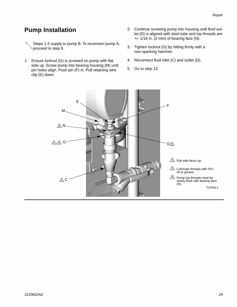
Circuit Breaker Module
1. Turn main power OFF . Disconnect powersupply. Turn circuit breakers on to test.
2. Relieve pressure, page 26.
3. Using an ohmmeter, check for continuity across cir-cuit breaker (top to bottom). If no continuity, tripbreaker, reset, and retest. If still no continuity,replace breaker as follows:
a. Refer to electrical diagrams and to TABLE 2. Dis-connect wires and remove bad breaker.
b. Install new breaker and reconnect wires.
* Depending on model.
Table 2: Circuit Breakers, see FIG. 1
Ref. Size Component
909 50A Hose/TransformerSecondary Side
911 40A TransformerPrimary
912A 25A, 40A* Heater A
912B 25A, 40A* Heater B
913 20A Motor/Pumps
FIG. 1. Circuit Breaker Module
ti9884a
912A
913
909
911
NOTE: To reference cables and con-nectors, see the electrical diagrams andthe parts drawings on pages 69-70.
912B

Repair
36 312066ZAD
Electric Motor
Removal
1. Turn main power OFF . Disconnect power
supply.
2. Relieve pressure, page 26.
3. Remove drive housing/pump assemblies, page 31.
4. Disconnect motor cables as follows:
a. Refer to electrical diagrams. Motor controlboard is on right side inside cabinet, see page37.
b. Unplug motor power harness from connector J4on board. See FIG. 2, page 38.
c. Unplug 3-pin connector J7 from board.
d. Thread cables through top of cabinet to freemotor.
5. Remove screws holding motor to bracket. Lift motoroff unit.
Installation
1. Place motor on unit. Thread motor cables into cabi-net and into bundles as before. See electrical dia-grams.
2. Fasten motor with screws.
3. Plug 3-pin connector J7 to board.
4. Plug motor power harness to connector J4 onboard.
5. Install drive housing/pump assemblies, page 31.
6. Return to service.
CAUTIONMotor is heavy. Two people may be required to lift.

Repair
312066ZAD 37
Motor Control Board
1. Turn main power OFF . Disconnect power
supply.
2. Relieve pressure, page 26.
3. Refer to electrical diagrams. Motor control board ison right side inside cabinet.
4. Put on static conductive wrist strap.
5. Disconnect all cables and connectors from board.
6. Remove nuts (40) and take entire motor controlassembly to workbench.
7. Remove screws and take board off heatsink.
8. Set DIP switch (SW2) on new board. See TABLE 3for factory settings. See FIG. 2 for location on board.
9. Install new board in reverse order. Apply thermalheatsink compound to mating surfaces of board andheatsink.
Motor control board has one red LED (D11). Powermust be on to check. See FIG. 2 for location. Func-tion is:
• Startup: 1 blink for 60 Hz, 2 blinks for 50 Hz.• Motor running: LED on.• Motor not running: LED off.• Diagnostic code (motor not running): LED
blinks diagnostic code, pauses, then repeats(for example, E21=21 blinks, pause, 21 blinks).
CAUTIONBefore handling board, put on a static conductivewrist strap to protect against static discharge whichcan damage board. Follow instructions provided withwrist strap.
Wait 5 minutes for stored voltage to discharge (E-30and E-XP2 models only).
Table 3: DIP Switch (SW2) Settings
DIPSwitch Switch Position
Switch 1 not usedSwitch 2 ON for E-20 and
E-30 modelsOFF for E-XP1 and
E-XP2Switch 3 ON to enable
pressure imbalancealarm
OFF to enablepressure imbalance
warningSwitch 4 not used
Order Part 110009 Thermal Compound.
Table 4: Motor Control Board Connectors
ModelE-20and
E-XP1
ModelE-30and
E-XP2 Pin Description
J1 N, L n/a Main motor power
J8 J3 n/a Transducer B
J4 J1 n/a Motor output
J7 J6 1, 2 Motor thermal overload signal
3 Brush wear signal
J3 J5 n/a Transducer A
J10 J7 1-4 Not used
5, 6 Cycle switch signal
7-10 Jumper 15C866 (available inrepair kit 246961)
J12 J12 n/a Data reporting
J13 J13 n/a To display board

Repair
38 312066ZAD
FIG. 2. Motor Control Board
1
Apply 110009 thermal heatsinkcompound to mating surfaces.
1
TI2576A-1
TI3153A-1
24G879 Motor Control, for E-20 and E-XP1
24G881 Motor Control, for E-30 and E-XP2
J3 (A)
J8 (B)
J1
J4J7
J13 J10
L
J1
J6
J13
J7
J3 (B)
J5 (A)
1
D11
D7
J12
J12
SW2
SW2
N
DIP Switch (SW2) Settings
TI3178b-2
TI3178b-1
Model E-XP2
Model E-30
DIP Switch (SW2) Settings
Model E-20
Model E-XP1
TI3178b-3
TI3178b-4
ON (UP)
ON (UP)
ON (Down)
ON (Down)

Repair
312066ZAD 39
Transducers
1. Turn main power OFF . Disconnect power
supply.
2. Relieve pressure, page 26.
3. Refer to electrical diagrams. Motor control board ison right side inside cabinet.
4. Disconnect transducer cables at board; see FIG. 2,page 38. Reverse A and B connections and check if
diagnostic code follows; see E21: No component Atransducer, page 15.
5. If transducer fails test, thread cable through top ofcabinet. Note path as cable must be replaced insame way.
6. Install o-ring (820) on new transducer (806), FIG. 3.
7. Install transducer in manifold. Mark end of cablewith tape (red=transducer A, blue=transducer B).
8. Route cable into cabinet and thread into bundle asbefore.
9. Connect transducer cable at board; see FIG. 2, page38.
Electric Fan
1. Turn main power OFF . Disconnect power
supply.
2. Relieve pressure, page 26.
3. Check fuses (F) at left of breaker module, FIG. 4.Replace if blown. If good, continue with step 4.
4. Refer to electrical diagrams. Disconnect fan wiresfrom fuses (F).
5. Remove fan.
6. Install fan in reverse order.
FIG. 3. Transducers
TI10957a
820
806 (B Side)
801
806 (A Side)
FIG. 4. Fan Fuses
F
ti9884a-1

Repair
40 312066ZAD
Temperature Control Module
Table 6: Temperature Power Module Connections
Table 5: Temperature Control Module Connections
Connector Description
DATA (A) Data reporting
SENSOR (B)
PINHOSE T/C P; FTS (purple)12
11 HOSE T/C R; FTS (red)10 HOSE T/C S; FTS (silver
(unshielded bare wire))9 HEATER T/C B, Y;
Thermocouple (yellow)8 HEATER T/C B, R;
Thermocouple (red)7 Not used6 HEATER T/C A, Y;
Thermocouple (yellow)5 HEATER T/C A, R;
Thermocouple (red)4, 3 OVERTEMPERATURE B;
Overtemperature switch B2, 1 OVERTEMPERATURE A;
Overtemperature switch ADISPLAY (C) Display
COMMUNICATION (D) Communication to powerboards
PROGRAM (E) Software programmingBOOT (F) Software bootloader
POWER/RELAY (G) Circuit board power input andcontactor control output
Connector Description
COMMUNICATION(H)
Communication to controlboard
POWER (J) Power to heater
FIG. 5: Temperature Control Module Connections
A
B
C
Bottom of Power Modules
Right Side ofControl Heater Module
D
E
F
G
ti9875a
ti9843a1
ti9843a4
H
J

Repair
312066ZAD 41
Test SCR Circuit
1. Test the SCR circuit in the on position:
a. Make sure everything is connected, includingthe hose.
b. Turn main power ON .
c. Adjust the hose heat setpoint above the ambi-ent hose temperature.
d. Turn on heat zone by pressing .
e. Hold down to view electrical current.
Hose current should ramp up to 45A. If there isno hose current, see E03: No zone current,page 13. If hose current exceeds 45A, see E02:High zone current, page 12. If hose currentstays several amps below 45A, hose is too longor voltage is too low.
2. Test the SCR circuit in the off position:
a. Make sure everything is connected, includingthe hose.
b. Turn main power ON .
c. Adjust the hose heat setpoint below the ambi-ent hose temperature.
d. Turn on heat zone by pressing .
e. Using a voltmeter, carefully measure the voltageat the hose connector. You should not get a volt-age reading. If you do, the SCR on the tempera-ture control board is bad. Replace thetemperature control assembly.
Replacing Temperature Control AssemblyModules
1. Turn main power OFF . Disconnect power
supply.
2. Relieve pressure, page 26.
3. Refer to electrical diagrams; see Electrical Dia-grams manual 312067. Temperature control assem-bly is on left side inside cabinet.
4. Remove bolts that secure transformer assembly andslide assembly to side in cabinet.
5. Put on static conductive wrist strap.
6. Disconnect all cables and connectors from assem-bly; see Parts - Temperature Control, page 66.
7. Remove nuts and take entire temperature controlassembly to workbench.
8. Replace defective module.
9. Install assembly in reverse order.
CAUTIONBefore handling assembly, put on a static conductivewrist strap to protect against static discharge whichcan damage assembly. Follow instructions providedwith wrist strap.

Repair
42 312066ZAD
Primary Heaters
Heater Element
1. Turn main power OFF . Disconnect power
supply.
2. Relieve pressure, page 26.
3. Wait for heaters to cool.
4. Remove heater shroud.
5. See FIG. 6. Disconnect heater element wires fromheater wire connector. Test with ohmmeter.
6. To remove heater element, first remove thermocou-ple (310) to avoid damage, see step 7, page 44.
7. Remove heater element (307) from housing (301).Be careful not to spill any fluid left in housing.
8. Inspect element. It should be relatively smooth andshiny. If there is a crusted, burnt, ash-like materialadhered to element or sheath shows pitting marks,replace element.
9. Install new heater element (307), holding mixer(309) so it does not block thermocouple port (P).
10. Reinstall thermocouple, page 44.
11. Reconnect heater element leadwires to heater wireconnector.
12. Replace heater shroud.
Line Voltage
The primary heaters output their rated wattage at 230Vac. Low line voltage will reduce power available andthe heaters will not perform at full capability.
Total HeaterWattage Element Ohms
6,000 1500 30-35
7,650 2550 18-21
10,200 2550 18-21

Repair
312066ZAD 43
FIG. 6. Heater (7.5 kW Single Zone Heater Shown)
303
304
309
315
308
310311
301
r_247813_312066
305
306
Apply 110009 thermal heatsink compound.1
1 304
313
313
307

Repair
44 312066ZAD
Thermocouple
1. Turn main power OFF . Disconnect power
supply.
2. Relieve pressure, page 26.
3. Wait for heaters to cool.
4. Remove heater shroud.
5. Disconnect thermocouple wires from B on tempera-ture control module. See TABLE 5, page 40 and FIG.5, page 40.
6. Feed thermocouple wires out of cabinet. Note pathas wires must be replaced in the same way.
7. See FIG. 7. Loosen ferrule nut (N). Remove thermo-couple (310) from heater housing (301), thenremove thermocouple housing (H). Do not removethe thermocouple adapter (305) unless necessary. If
adapter must be removed, ensure that mixer (309)is out of the way when replacing the adapter.
8. Replace thermocouple, FIG. 7.
a. Remove protective tape from thermocouple tip(T).
b. Apply PTFE tape and thread sealant to malethreads and tighten thermocouple housing (H)into adapter (305).
c. Push in thermocouple (310) so tip (T) contactsheater element (307).
d. Holding thermocouple (T) against heater ele-ment, tighten ferrule nut (N) 1/4 turn past tight.
9. Route wires (S) into cabinet and thread into bundleas before. Reconnect wires to board.
10. Replace heater shroud.
11. Turn on heaters A and B simultaneously to test.Temperatures should rise at same rate. If oneheater is low, loosen ferrule nut (N) and tighten ther-mocouple housing (H) to ensure thermocouple tip(T) contacts element (307).
FIG. 7. Thermocouple
309
301
S
N
H
T
307
Apply PTFE tape and thread sealant.1
1
308
ti7924a
Apply 110009 thermal heatsink compound.2
2
310
35

Repair
312066ZAD 45
Overtemperature Switch
1. Turn main power OFF . Disconnect power
supply.
2. Relieve pressure, page 26.
3. Wait for heaters to cool.
4. Remove heater shroud.
5. Disconnect one leadwire from overtemperatureswitch (308), FIG. 7. Test across switch with ohmme-ter. Resistance must be approximately 0 ohms.
6. If switch fails test, remove wires and screws. Dis-card failed switch. Apply thermal compound110009, install new switch in same location onhousing (301), and secure with screws (311).Reconnect wires.
Heated Hose
Check Hose Power Connectors
1. Turn main power OFF . Disconnect power
supply.
2. Relieve pressure, page 26.
3. Disconnect power wire harness from terminal block(TB).
4. Use an ohmmeter to check for continuity betweenthe two terminals (C, E) on the terminal block.
5. If the hose fails the test, re-test at each length ofhose, including whip hose, until the failure is identi-fied.
6. Disconnect power wires from power splice connec-tors (12).
7. Use an ohmmeter to check for continuity betweenthe two connectors (12) at (z).
8. If the hose fails the test, re-test at each length ofhose, including whip hose, until the failure is identi-fied.
If wires need replacement, disconnect from tem-perature control board. See TABLE 5, page 40 andFIG. 5, page 40.
Refer to the heated hose manual 309572 for hosereplacement parts.
Whip hose must be connected.
For proportioners with a termination box (TB), fol-low steps 3 - 5. For proportioners with electricalsplice connectors (12), follow steps 6 - 8.
12
3
4
z
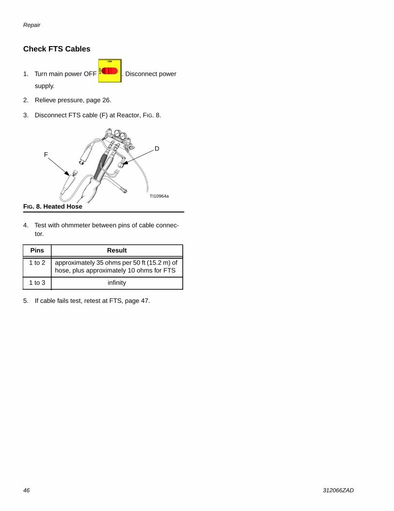
Repair
46 312066ZAD
Check FTS Cables
1. Turn main power OFF . Disconnect power
supply.
2. Relieve pressure, page 26.
3. Disconnect FTS cable (F) at Reactor, FIG. 8.
4. Test with ohmmeter between pins of cable connec-tor.
5. If cable fails test, retest at FTS, page 47.
FIG. 8. Heated Hose
Pins Result
1 to 2 approximately 35 ohms per 50 ft (15.2 m) ofhose, plus approximately 10 ohms for FTS
1 to 3 infinity
TI10964a
FD

Repair
312066ZAD 47
Fluid Temperature Sensor (FTS)Test/Removal
1. Turn main power OFF . Disconnect power
supply.
2. Relieve pressure, page 26.
3. Remove tape and protective covering from FTS(21), FIG. 8. Disconnect hose cable (F). Test withohmmeter between pins of cable connector.
4. If FTS fails any test, replace FTS.
5. Disconnect air hoses (C, L), and electrical connec-tors (D).
6. Disconnect FTS from whip hose (W) and fluid hoses(A, B).
7. Remove ground wire (K) from ground screw onunderside of FTS.
8. Remove FTS probe (H) from component A (ISO)side of hose.
Installation
The Fluid Temperature Sensor (FTS) is supplied. InstallFTS between main hose and whip hose. See HeatedHose manual 309572 for instructions.
Pins Result
1 to 2 approximately 10 ohms
1 to 3 infinity
3 to FTS groundscrew 0 ohms
1 to FTS component Afitting (ISO)
infinity
FIG. 9: Fluid Temperature Sensor and Heated Hoses
A
B
HC
LISO
A
W
BD
K
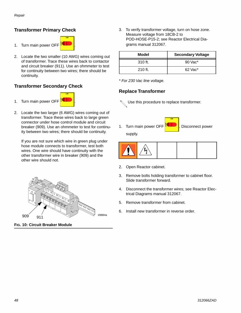
Repair
48 312066ZAD
Transformer Primary Check
1. Turn main power OFF .
2. Locate the two smaller (10 AWG) wires coming outof transformer. Trace these wires back to contactorand circuit breaker (911). Use an ohmmeter to testfor continuity between two wires; there should becontinuity.
Transformer Secondary Check
1. Turn main power OFF .
2. Locate the two larger (6 AWG) wires coming out oftransformer. Trace these wires back to large greenconnector under hose control module and circuitbreaker (909). Use an ohmmeter to test for continu-ity between two wires; there should be continuity.
If you are not sure which wire in green plug underhose module connects to transformer, test bothwires. One wire should have continuity with theother transformer wire in breaker (909) and theother wire should not.
3. To verify transformer voltage, turn on hose zone.Measure voltage from 18CB-2 toPOD-HOSE-P15-2; see Reactor Electrical Dia-grams manual 312067.
* For 230 Vac line voltage.
Replace Transformer
1. Turn main power OFF . Disconnect power
supply.
2. Open Reactor cabinet.
3. Remove bolts holding transformer to cabinet floor.Slide transformer forward.
4. Disconnect the transformer wires; see Reactor Elec-trical Diagrams manual 312067.
5. Remove transformer from cabinet.
6. Install new transformer in reverse order.
FIG. 10: Circuit Breaker Module
909 911ti9884a
Model Secondary Voltage
310 ft. 90 Vac*
210 ft. 62 Vac*
Use this procedure to replace transformer.

Repair
312066ZAD 49
Display Module
Temperature and Pressure Displays
1. Turn main power OFF . Disconnect power
supply.
2. Relieve pressure, page 26.
3. Refer to electrical diagrams.
4. Put on static conductive wrist strap.
5. Disconnect main display cable (20) at lower left cor-ner of display module; see FIG. 11.
6. Remove screws (509, 510) and cover (504); seeFIG. 11.
7. Disconnect cable connectors (506 and 511) fromback of temperature display (501) or pressure dis-play (502); see FIG. 11.
8. Disconnect ribbon cable(s) (R) from back of display;see FIG. 11.
9. Remove nuts (508) and plate (505).
10. Disassemble display, see detail in FIG. 11.
11. Replace board (501a or 502a) or membrane switch(501b or 502b) as necessary.
12. Reassemble in reverse order, see FIG. 11. Applymedium strength thread sealant where shown. Besure display cable ground wire (G) is securedbetween cable bushing and cover (504) with screws(512).
Red Stop Button
1. Turn main power OFF . Disconnect power
supply.
2. Relieve pressure, page 26.
3. Refer to electrical diagrams.
4. Put on static conductive wrist strap.
5. Remove screws (509, 510) and cover (504), FIG. 11.
6. Disconnect button cable connectors (506) from backof temperature display (501) and pressure display(502).
7. Remove red stop button (506).
8. Reassemble in reverse order. Be sure display cableground wire (G) is secured between cable bushingand cover (504) with screws (512).
CAUTIONBefore handling board, put on a static conductivewrist strap to protect against static discharge whichcan damage board. Follow instructions provided withwrist strap.
If replacing both displays, label temperature displaycables TEMP and pressure display cables PUMPbefore disconnecting.
CAUTIONBefore handling board, put on a static conductivewrist strap to protect against static discharge whichcan damage board. Follow instructions provided withwrist strap.

Repair
50 312066ZAD
FIG. 11. Display Module
ti2574a
502
501
503
504
505
506
507
508
510
511
512
506
ti3172a
20
501a
501c
501b
502b
502c
502a
G
511
R
R
Detail of Membrane Switches and Display Boards
Temperature Display Pressure Display
Apply medium strength thread sealant.1
1
1
1
1

Repair
312066ZAD 51
Inlet Fluid Strainer Screen
The inlet strainer at each proportioning pump filters outsolid matter that can plug the inlet check valves. Inspectthe screens daily as part of the startup routine, andclean as required.
Isocyanate can crystallize from moisture contaminationor from freezing. If the chemicals used are clean andproper storage, transfer, and operating procedures arefollowed, there should be minimal contamination of theA-side screen.
1. Close the material supply valve at the pump inlet toprevent material from being pumped while thestrainer plug (C) is removed.
2. Place a container under the strainer base to catchdrain off when removing the strainer plug.
3. Remove the screen (A) from the strainer manifold.Thoroughly flush the screen with gun cleaner andshake it dry. Inspect the screen for blockage. Nomore than 25% of the mesh should be restricted. Ifmore than 25% is blocked, replace the screen.Inspect the strainer gasket (B) and replace asrequired.
4. Ensure the pipe plug (D) is securely screwed intothe strainer plug (C). Install the strainer plug with thescreen (A) and gasket (B) in place and tighten. Donot overtighten. Let the gasket make the seal.
5. Open the material supply valve, ensure that thereare no leaks, and wipe the equipment clean.
6. Proceed with operation.
* Fluid filter screen (59g) replacements:
Clean the A-side screen only during daily startup.This minimizes moisture contamination by immedi-ately flushing out any isocyanate residue at thestart of dispensing operations.
FIG. 12. Y Strainer Components
Part Description26A349 KIT, filter, replacement; 2 pack26A350 KIT, filter, replacement; 10 pack
A*
B
CD
TI10974a

Repair
52 312066ZAD
Pump Lubrication System
Check the condition of the ISO pump lubricant daily.Change the lubricant if it becomes a gel, its color dark-ens, or it becomes diluted with isocyanate.
Gel formation is due to moisture absorption by the pumplubricant. The interval between changes depends on theenvironment in which the equipment is operating. Thepump lubrication system minimizes exposure to mois-ture, but some contamination is still possible.
Lubricant discoloration is due to continual seepage ofsmall amounts of isocyanate past the pump packingsduring operation. If the packings are operating properly,lubricant replacement due to discoloration should not benecessary more often than every 3 or 4 weeks.
To change pump lubricant:
1. Relieve pressure, page 26.
2. Lift the lubricant reservoir (LR) out of the bracket(RB) and remove the container from the cap. Hold-ing the cap over a suitable container, remove theinlet check valve and allow the lubricant to drain.Reattach the inlet check valve to the inlet hose. SeeFIG. 13.
3. Drain the reservoir and flush it with clean lubricant.
4. When the reservoir is flushed clean, fill with freshlubricant.
5. Thread the reservoir onto the cap assembly andplace it into the bracket.
6. The lubrication system is ready for operation. Nopriming is required.
FIG. 13. Pump Lubrication System
LR
RTST
RB
TI10970a
TI10969a
LR
STRT
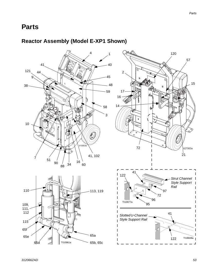
Parts
312066ZAD 53
Parts
Reactor Assembly (Model E-XP1 Shown)
TI10961a
57
65a
65b, 65c65d
65e
65f
72
14
17
2
4 1
40
45
58
59
3
7
10
44
38
9
115
120
15
1690
41
41, 102 21
109,
110 113, 119
121
34
48
6088
51
TI10977a
97
41122
9596
72
111,112 41
122 TI18608a
Strut ChannelStyle SupportRail
SlottedU-ChannelStyle Support Rail
16

Parts
54 312066ZAD
8
Left Side of Cabinet
Right Side of Cabinet
42
5
123
61, 62
39, 52, 71, 73
76
33
27
6
29, 42
TI9835a
TI10968a
41
77
31, 42
36 (400Vmodels only)
28

Parts
312066ZAD 55
Detail, Fluid Manifold AreaDetail, Fluid Manifold Area
Detail, Cabinet Area
TI10978a
35
87
13
26
41
38
41
61
24
25
57
mounting base (from motor)

Parts
56 312066ZAD
Parts Used on All ModelsSee pages 57 through 59 for parts that vary by model.
▲ Replacement Danger and Warning labels, tags, and cardsare available at no cost.
* See quantity on referenced pages.
† Not shown.
★ Required for all A-F series models. Included in KnobRepair Kit 258920 (purchase separately).
◆ Not required for slotted U-Channel style heater supportrails.
✓ For models series A - E.
✿ For models series F.
Ref. Part Description Qty1 FRAME; page 64 12 HEATER; pages 62 and 63 *3 MODULE, proportioner; page 60 *4 245974 DISPLAY; page 65 15 CONTROL, temperature; page 66 16 CONTROL, motor; page 67 *7 247823 MANIFOLD, fluid; page 68 18 TRANSFORMER; pages 57-59 *9 SHIELD; page pages 57-59 *10 246976 DOOR, cabinet 111† 261669 SENSOR, fluid temperature 112 15B456 GASKET, manifold 113 115834 FAN 114 TUBE, heater component A; pages
57-59*
15 TUBE, pump, component A; pages57-59
*
16 TUBE, heater component B; pages57-59
*
17 TUBE, pump, component B; pages57-59
*
18† 247787 CABLE, overtemperature; see electricaldiagrams
1
19† 15B380 CABLE, hose control; see electrical dia-grams
1
20 15B383 CABLE, display 121 CONNECTOR, tube; pages 57-59 *22 116773 CONNECTOR, plug 123 C38163 WASHER, lock, external tooth 124 15B361 BOOT, wire feed through 125 15B510 PLATE, cover, wire 126 15B360 GASKET, fan 127 255047 STRAIN RELIEF 128 MODULE, breaker; pages 57-59 *29 116149 SPACER 831 117666 TERMINAL, ground 133★ 123969 SWITCH, disconnect 134★ 123967 SWITCH, main power 135 117723 SCREW, machine; 6-32 x 2 in. (51 mm) 436 SWITCH, added pole; 380V; page 57 *38 115492 SCREW, machine; 8-32 x 0.345 in. (9
mm)13
39 FILTER; 230V; page 57 *40 117623 NUT, cap; 3/8-16 441 113796 SCREW, flanged, hex hd; 1/4-20 x 3/4
in. (19 mm)15
42 115942 NUT, hex flange; 1/4-20 1544 15K817 LABEL, diagnostic codes 145 189930 LABEL, caution 348▲ 189285 LABEL, caution 351▲ LABEL, warning; pages 57-59 *52 CABLE. harness, filter; pages 57-59 *53 15B593 SHIELD, membrane switch; pack of 10 157 15B775 COVER, wire access 258 247524 COVER, heater, back 159 256732 COVER, heater, front 160▲ 15G280 LABEL, warning 161 113505 NUT, hex, keps; 10-24 662 112776 WASHER, plain; no. 10 265 KIT, fluid inlet 165a FITTING, swivel, elbow 265b 101078 Y-STRAINER 265c† 26A349 KIT, filter, replacement (2 pack) 1
26A350 KIT, filter, replacement (10 pack) 165d C20487 NIPPLE, 3/4 npt 2
65e 109077 VALVE, ball; 3/4 npt (fbe) 265f 118459 FITTING, union, swivel; 3/4-14 npt(m) x
3/4-14 npt(f)2
66 101078 Y-STRAINER; includes 66a 266a† 26A349 KIT, filter, replacement (2 pack) 1
26A350 KIT, filter, replacement (10 pack) 167 109077 VALVE, ball; 3/4 npt (fbe) 268 C20487 NIPPLE; 3/4 npt 269 157785 UNION, swivel; 3/4 npt(m) x 3/4 npsm(f) 271 SCREW, machine; pages 57-59 *72◆ BRACKET. heater; pages 57-59 *73 WASHER, lock; pages 57-59 *76 CAPACITOR; pages 57-59 *77 BRACKET; pages 57-59 *86 CABLE, overtemperature, jumper;
pages 57-59*
87 15B807 SHIELD, fan 188 186494 CLIP, spring 689 205447 COUPLING, hose 290 15M338 TUBE, low pressure; 1/4 in. (6 mm) ID;
3/8 in. (16 mm) OD; 4 ft (1.2 m); PTFE1
95◆ BOLT; hex hd; pages 57-59 *96◆ LOCKWASHER; 3/8; pages 57-59 *97◆ NUT, channel; pages 57-59 *102 STRAP, motor; pages 57-59 *106 117502 REDUCER; #5 x #8 JIC 1107 117677 REDUCER; #6 x #10 JIC 1109 246928 RESERVOIR; includes 110-119; see
3099111
110 054826 TUBE; PTFE; 1/4 in. (6 mm) ID;2 ft (0.6 m)
2
111 118433 VALVE, check 1112 118432 VALVE, check 1113 116746 FITTING, barbed 2115 15C568 BRACKET, reservoir 1117 206995 THROAT SEAL LIQUID; 1 qt (1 liter) 1119 191892 ELBOW; 1/8 npt (m x f) 2120▲ 171001 LABEL, warning 1121 LABEL; pages 57-59 *122 INSULATOR, heat; pages 57-59 *123 247782 SPACER 4124 247854 COVER, connector, module 1125 114331 SCREW, machine; 6-32 x 0.375 in. (9.5
mm)2
127✓ 261821 CONNECTOR, wire 1138✿ 24W204 ENCLOSURE, TB 1139✿ 25A234 ENCLOSURE, cover 1140✿▲ 189930 LABEL, caution 1141✿ 16X129 SCREW 8142✿ 17C082 CABLE, lanyard 1
Ref. Part Description Qty

Parts
312066ZAD 57
Parts that Vary by Model
Use the following tables on this and the next two pages to find parts that vary by model. Find the reference numberand of part in left column and Reactor model in top row. Intersection is correct part number.
See page 56 for parts common to all models.
Ref. Description
Reactor ModelsQty
259024E-XP1
259025E-20
259026E-30
259028E-XP2
259029E-XP1
259030E-20
259031E-30
259032E-XP2
259033E-XP1
259034E-20
259035E-30
259036E-XP2
2 HEATER; pages62 and 63 247507 247506 247507 247509
(qty: 2) 247507 247506 247507 247509(qty: 2) 247507 247506 247507 247509
(qty: 2) 1
3 MODULE, pro-portioner; page60
245956 245956 245957 245959 245956 245956 245957 245959 245956 245956 245957 245959 1
6 CONTROL,motor; page 67 24G879 24G879 24G881 24G881 24G879 24G879 24G881 24G881 24G879 24G879 24G881 24G881 1
8 TRANS-FORMER; 247840 247840 247812 247812 247840 247840 247812 247812 247840 247840 247812 247812 1
9 SHIELD 276878 276878 276879 276879 276878 276878 276879 276879 276878 276878 276879 276879 1
14 TUBE, heater,component A 247920 247920 247920 247915 247920 247920 247920 247915 247920 247920 247920 247915 1
15 TUBE, pump,component A 247912 247912 247919 247914 247912 247912 247919 247914 247912 247912 247919 247914 1
16 TUBE, heater,component B 247918 247918 247918 247917 247918 247918 247918 247917 247918 247918 247918 247917 1
17 TUBE, pump,component B 247913 247913 247921 247916 247913 247913 247921 247916 247913 247913 247921 247916 1
21 CONNECTOR,tube 121310 121310 121311 121311 121310 121310 121311 121311 121310 121310 121311 121311 2
28 MODULE,breaker; page 69 C C F F B B E E A A D D 1
36 SWITCH, addedpole; 380V 123968 123968 123968 123968 1
39 FILTER; 230V 117667 117667 117667 117667 117667 117667 1

Parts
58 312066ZAD
51▲ LABEL, warning 198278 198278 198278 198278 198278 198278 1
52 CABLE,harness,filter 15B385 15B385 15B385 15B385 15B385 15B385 1
65 KIT, fluid inlet 234366 234366 234367 234366 234366 234366 234367 234366 234366 234366 234367 234366 1
65a ELBOW, swivel;3/4 npt(m) x 1”npt(f)
160327 160327 118463 160327 160327 160327 118463 160327 160327 160327 118463 160327 2
71 SCREW,machine --- --- --- --- --- --- 2
72◆ BRACKET,heater 247523 247523 247523 247523 247523 247523 247523 247523 247523 2
BRACKET,heater 247523 247523 247523 4
73 WASHER, lock 103181 103181 103181 103181 103181 103181 2
76 CAPACITOR 244733 244733 244733 244733 244733 244733 1
77 BRACKET 197999 197999 197999 197999 197999 197999 1
86 CABLE, over-temperature,jumper
15H187 15H187 15H187 15H187 15H187 15H187 15H187 15H187 15H187 1
95◆ BOLT; hex hd;3/8-16 100469 100469 100469 100469 100469 100469 100469 100469 100469 2
BOLT; hex hd;3/8-16 100469 100469 100469 4
96◆ LOCKWASHER;3/8 100133 100133 100133 100133 100133 100133 100133 100133 100133 2
LOCKWASHER;3/8 100133 100133 100133 4
97◆ NUT, channel 118446 118446 118446 118446 118446 118446 118446 118446 118446 2
NUT, channel 118446 118446 118446 4
102 STRAP, motor 15B107 15B107 15B108 15B108 15B107 15B107 15B108 15B108 15B107 15B107 15B108 15B108 1
121 LABEL 15M504 15M500 15M499 15M501 15M504 15M500 15M499 15M501 15M504 15M500 15M499 15M501 1
122 INSULATOR 167002 167002 167002 167002(qty: 4) 167002 167002 167002 167002
(qty: 4) 167002 167002 167002 167002(qty: 4) 2
Ref. Description
Reactor ModelsQty
259024E-XP1
259025E-20
259026E-30
259028E-XP2
259029E-XP1
259030E-20
259031E-30
259032E-XP2
259033E-XP1
259034E-20
259035E-30
259036E-XP2

Parts
312066ZAD 59
Parts that Vary by Model (continued)
▲ Replacement Danger and Warning labels, tags, andcards are available at no cost.
◆ Not required for slotted U-Channel style heater sup-port rails.
--- Not for sale.
Ref. Description
Reactor ModelsQty
259057E-30w/15.3kW
259058E-30w/15.3kW
259059E-30w/15.3kW
2 HEATER; pages62 and 63 247509 247509 247509 2
3 MODULE, pro-portioner; page60
245957 245957 245957 1
6 CONTROL,motor; page 67 24G881 24G881 24G881 1
8 TRANSFORMER; 247812 247812 247812 1
9 SHIELD 276879 276879 276879 1
14 TUBE, heater,component A 247915 247915 247915 1
15 TUBE, pump,component A 247914 247914 247914 1
16 TUBE, heater,component B 247917 247917 247917 1
17 TUBE, pump,component B 247916 247916 247916 1
21 CONNECTOR,tube 121311 121311 121311 2
28 MODULE,breaker; page 69 F D E 1
36 SWITCH, addedpole; 380V 123968 1
39 FILTER; 230V 117667 117667 117667 1
51▲ LABEL, warning 198278 198278 198278 1
52 CABLE, harness,filter 15B385 15B385 15B385 1
65 KIT, fluid inlet 234367 234367 234367 1
65a ELBOW, swivel;3/4 npt(m) x 1”npt(f)
118463 118463 118463 2
71 SCREW,machine --- --- --- 2
72◆ BRACKET,heater 247523 247523 247523 4
73 WASHER, lock 103181 103181 103181 2
76 CAPACITOR 244733 244733 244733 1
77 BRACKET 197999 197999 197999 1
95◆ BOLT; hex hd;3/8-16 100469 100469 100469 4
96◆ LOCKWASHER;3/8
LOCKWASHER;3/8 100133 100133 100133 4
97◆ NUT, channel
NUT, channel 118446 118446 118446 4
102 STRAP, motor 15B108 15B108 15B108 1
121 LABEL 15M499 15M499 15M499 1
122 Insulator 167002 167002 167002 4
Ref. Description
Reactor ModelsQty
259057E-30w/15.3kW
259058E-30w/15.3kW
259059E-30w/15.3kW

Parts
60 312066ZAD
Sub Assemblies
Proportioner Module
Detail of Cycle Counter Switch
TI2511a
TI3250a
245956 Module for E-20 and EXP-1
245957 Module for E-30
245959 Module for EXP-2
201
202
203
204
205
206A
*207208
209
**210
211
212
213214
215
216
217
218
219
*208
214
221
1
Flat side faces up.1
220
206B211210**
216 1
225
224
226

Parts
312066ZAD 61
Proportioner Assembly
245956 Module, for E-20 and E-XP1
245957 Module, for E-30
245959 Module, for E-XP2
* Parts included in Gear Kit 244264 (245956) or244265 (245957, 245959).
** Parts included in Connecting Rod Kit 241008(245956) or 241279 (245957, 245959).
Ref. Part Description Qty201 24V618 MOTOR; 245956 1
24V500 MOTOR; 245957, 245959 1202 245968 HOUSING, drive; 245956 2
245969 HOUSING, drive; 245957, 245959 2203 240523 HOUSING, bearing; 245956 2
241015 HOUSING, bearing; 245959 2245927 HOUSING, bearing; 245957 2
204 244264 GEAR; includes items 207, 208;245956
2
244265 GEAR; includes items 207, 208;245957, 245959
2
205 241008 ROD, connecting; includes item 210;245956
2
241279 ROD, connecting; includes item 210;245957, 245959
2
206A 246830 PUMP, displacement, component A;245956; see 309577
1
246831 PUMP, displacement, component A;245959; see 309577
1
246832 PUMP, displacement, component A;245957; see 309577
1
206B 245970 PUMP, displacement, component B;245956; see 309577
1
245971 PUMP, displacement, component B;245959; see 309577
1
245972 PUMP, displacement, component B;245957; see 309577
1
207* 114699 WASHER, thrust; steel 2208* 114672 WASHER, thrust; bronze 4209 114418 SCREW, self-tapping; 8-32 x 1 in. (25
mm); 2459568
114818 SCREW, self-tapping; 8-32 x 1-1/4 in.(31 mm); 245957, 245959
8
210** 176817 CLIP, wire; 245956 2183169 CLIP, wire; 245957, 245959 2
211 176818 PIN; 245956 2183210 PIN; 245957, 245959 2
212 107218 SCREW, cap, socket-hd; 1/4-20 x 2-3/4in. (70 mm); 245956
4
114686 SCREW, cap, socket-hd; 5/16-18 x3-1/4 in. (83 mm); 245957, 245959
4
213 107210 SCREW, cap, socket-hd; 3/8-16 x 1-1/2in. (38 mm); 245956
8
114666 SCREW, cap, socket-hd; 3/8-16 x 2-1/4in. (57 mm); 245957, 245959
8
214 105510 WASHER, lock; 1/4; 245956 12104008 WASHER, lock; 5/16; 245957, 245959 12
215 106115 WASHER, lock; 3/8 size 8216 192723 NUT, retaining; 245956 2
193031 NUT, retaining; 245959 2193394 NUT, retaining; 245957 2
217 179899 COVER; 245956 2241308 COVER; 245957, 245959 2
218 116191 WASHER, thrust; 245956 2116192 WASHER, thrust; 245957, 245959 2
219 100644 SCREW, cap, socket-hd; 1/4-20 x 3/4in. (19 mm); 245956
4
101864 SCREW, cap, socket-hd; 5/16-18 x 1in. (25 mm); 245957, 245959
4
220 116618 MAGNET 1
221 117770 SWITCH, cycle counter 1223 100643 SCREW, cap, socket-hd; 1/4-20 x 1 in.
(25 mm); 2459564
102962 SCREW, cap, socket-hd; 5/16-18 x1-1/4 in. (31 mm); 245957, 245959
4
224 104765 PLUG 2225 15C587 GUARD, finger; 245956 1
15C588 GUARD, finger; 245959 1226 15M507 LABEL; 245956 1
15M508 LABEL; 245957, 245959 1
Ref. Part Description Qty

Parts
62 312066ZAD
Fluid Heaters
247506, 6.0 kW Fluid Heaters247507, 10.2 kW Fluid Heaters
r_247507_312408
Apply 110009 thermal heatsink compound.1
313
304
309
307
303
305
310
306
311
308 1
301
314
315
Ref Part DescriptionQty
.
301 HOUSING, heater 1
303 121309 ADAPTER 4
304 15H304 PLUG 2
305 15H306 ADAPTER, thermocouple 2
306 120336 O-RING; fluoroelastomer 2
307 HEATER, immersion 4
16A110 2550W; 10.2kW heater only
16A112 1500 W; 6.0 kW heater only
308 15B137 SWITCH, overtemperature 1
309 15B135 MIXER, immersion heater 4
310 117484 SENSOR 2
311 100518 SCREW, machine, pan hd 2
313 15H305 PLUG, hollow 4
314 247520 DISC, rupture 2
315 124132 O-RINGS 4
Ref Part DescriptionQty
.

Parts
312066ZAD 63
7.65 kW Single Zone Fluid Heater(Two Per Machine)
Part 247509
303
301
304
307
308
310311
305
306 1304
313
313
r_247813_312066
Apply 110009 thermal heatsink compound.1
309
314
315
Ref. Part Description Qty301 HOUSING, heater 1
303 121309 ADAPTER 2
304 15H304 PLUG 3
305 15H306 ADAPTER, thermocouple 1
306 120336 O-RING; fluoroelastomer 1
307 16A110 HEATER, immersion; 2550 W 3
308 15B137 SWITCH, overtemperature 1
309 15B135 MIXER, immersion heater 3
310 117484 SENSOR 1
311 100518 SCREW, machine, pan hd 2
313 15H305 PLUG, hollow 5
314 247520 DISC, rupture; not shown 1
315 124132 O-RING 3
Ref. Part Description Qty
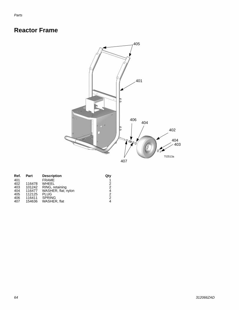
Parts
64 312066ZAD
Reactor Frame
TI2513a
405
401
406404
402
404403
407
Ref. Part Description Qty401 FRAME 1402 116478 WHEEL 2403 101242 RING, retaining 2404 116477 WASHER, flat; nylon 4405 112125 PLUG 2406 116411 SPRING 2407 154636 WASHER, flat 4

Parts
312066ZAD 65
Display
--- Not for sale.
ti2574a
502
501
503
504
505
506
507
508
510
511
512
506
511
ti3172a
501a
501c
501b
502b
502c502a
20 (Ref)
Ref. Part DescriptionQty
.501 24G884 DISPLAY, pressure; includes
501a-501c1
501a 24G882 .BOARD, circuit 1
501b 246478 .SWITCH, membrane 1
501c 112324 .SCREW 4
502 24G883 DISPLAY, temperature; includes502a-502c
1
502a 24G882 .BOARD, circuit 1
502b 246479 .SWITCH, membrane 1
502c 112324 .SCREW 4
503 15B293 GASKET 1
504 15B292 COVER 1
505 15B291 PLATE 1
506 246287 HARNESS, wire, red stop button 1
507 117499 HANDLE 2
508 117523 NUT, cap; 10-24 8
510 --- SCREW, machine, pan-hd; M5 x0.8; 16 mm
4
511 15B386 CABLE, display 1
512 195853 SCREW, machine; M2.5 x 6 2
Ref. Part DescriptionQty
.
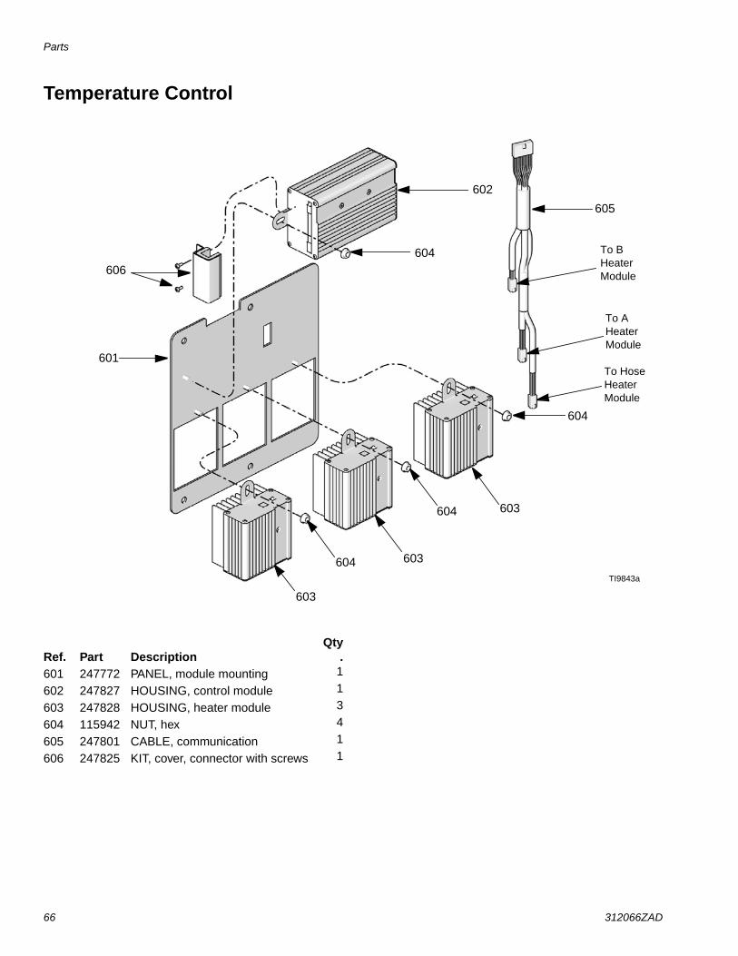
Parts
66 312066ZAD
Temperature Control
TI9843a
602
604
601
603
604
604
604
603
603
605
To BHeaterModule
To AHeaterModule
To HoseHeaterModule
606
Ref. Part DescriptionQty
.601 247772 PANEL, module mounting 1
602 247827 HOUSING, control module 1
603 247828 HOUSING, heater module 3
604 115942 NUT, hex 4
605 247801 CABLE, communication 1
606 247825 KIT, cover, connector with screws 1

Parts
312066ZAD 67
Motor Control
24G879 Motor Control for E-20 and EXP-1 24G881 Motor Control for E-30 and EXP-2
--- Not for sale.
24G879 Motor Control for E-20 and EXP-1
24G881 Motor Control for E-30 and EXP-2
TI3153a
TI2576a
702
703
701
1
Apply 110009 thermal heatsink compound to mating surfaces.1
701
702
705
703
704707
2
Motor harness (609) plugs in here.2
1
Ref. Part DescriptionQty
.701 15B297 HEAT SINK 1702 24G878 BOARD, motor control 1703 107156 SCREW, machine; 6-32 7
Ref. Part DescriptionQty
.701 16F745 HEAT SINK 1702 --- BOARD, motor control 1703 --- SCREW, machine;
6-32 x 3/8 in. (10 mm)6
704 117526 SPACER 3705 117683 SCREW, 6-32 x 1-1/2 in. (38 mm) 2707 15C007 INDUCTOR 1709 15B408 CABLE, harness, motor 1

Parts
68 312066ZAD
Fluid Manifold
▲ Replacement Warning labels, signs, tags, and cardsare available at no cost.
† Included in the following complete valve kits*:ISO Valve Kit (left/red handle) 255149.Resin Valve Kit (right/blue handle) 255150.Valve Set Kit (both handles and grease gun) 255148.
* Complete valve kits also include thread sealant.(Purchase kits separately).
TI10959a
Torque to 355-395 in-lb (40.1-44.6 N•m).
Apply sealant (113500) to threads.
Valve must be closed with handle position as shown on drawing.
** Apply PTFE tape or thread sealant to tapered threads.
1
2
3
808
806
818802
803
805
814
815
804
801 812
813 817
814
807
816
1
2
3
2
3
3
802a802b
Ref. Part DescriptionQty
.801 247837 MANIFOLD, fluid 1
802† 247824 VALVE, drain cartridge 2
802a† 158674 . O-RING 1
802b† 247779 . SEAL, seat, valve 1
803 102814 GAUGE, pressure, fluid 2
804 162453 FITTING, 1/4 npsm x 1/4 npt 2
805 24K999 TRANSDUCER, pressure, control 2
806 247788 HANDLE, red 1
807 247789 HANDLE, blue 1
808† 112309 NUT, hex, jam 2
812 117556 NIPPLE, #8 JIC x 1/2 npt 1
813 117557 NIPPLE, #10 JIC x 1/2 npt 1
814 121312 ELBOW, 90 degrees 2
815 100840 ELBOW, street; 1/4 npsm x 1/4 npt 2
816 111457 O-RING, PTFE 2
817▲ 189285 LABEL, caution 1
818† 150829 SPRING, compression 2
Ref. Part DescriptionQty
.
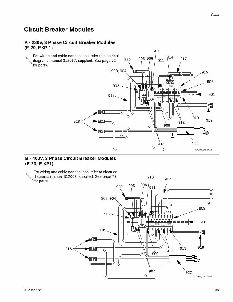
Parts
312066ZAD 69
Circuit Breaker Modules
178CB187CB
197CB172CB23
8CR
ti27065a_ 255185_vb
172CB197CB
187CB178CB
238C
R
168BR
ti27064a_ 255185_va
B - 400V, 3 Phase Circuit Breaker Modules(E-20, E-XP1)
For wiring and cable connections, refer to electricaldiagrams manual 312067, supplied. See page 72for parts.
A - 230V, 3 Phase Circuit Breaker Modules(E-20, EXP-1)
For wiring and cable connections, refer to electricaldiagrams manual 312067, supplied. See page 72for parts.
918
907
909912
913919
901
908
915
917914
916
911
910
906905920
902
903, 904
918
907
909912
913 919
901
908
917
916
911
910
906905920
902
903, 904
922
922

Parts
70 312066ZAD
172CB197CB187CB178CB
238C
R
168BR
ti27066a_ 255185_vc
C - 230V, 1 Phase Circuit Breaker Modules(E-20, EXP-1)
For wiring and cable connections, refer to electricaldiagrams manual 312067, supplied. See page 72for parts.
918
907
909912
913 919
901
908
915
917914
916
911
910
906905920
902
903, 904
D - 230V, 3 Phase Circuit Breaker Modules(E-30, EXP-2)
For wiring and cable connections, refer to electricaldiagrams manual 312067, supplied. See page 72for parts.
918
907
909 912913
901
908
915
917914
916
911
910
906905920
902
903, 904
919
922
922

Parts
312066ZAD 71
E - 400V, 3 Phase Circuit Breaker Modules(E-30, E-XP2)
For wiring and cable connections, refer to electricaldiagrams manual 312067, supplied. See page 72for parts.
918
907
909912
913
901
908
917
916
911
910
906905920
902
903, 904
F - 230V, 1 Phase Circuit Breaker Modules(E-30, EXP-2)
For wiring and cable connections, refer to electricaldiagrams manual 312067, supplied. See page 72for parts.
918
907
909912
913
919
901
908
915
917914
916
911
910
906905920
902
903, 904
919
922
922

Parts
72 312066ZAD
Circuit Breaker Modules Parts List
--- Not for sale.
✓ For models series A - E.
✿ For models series F.
Ref. Description
Breaker Modules
Qty
E-20 and EXP-1 Models E-30 and EXP-2 Models
A230V,
3 phase
B400V,
3 phase
C230V,
1 phase
D230V,
3 phase
E400V,
3 phase
F230V,
1 phase
901 RAIL, mounting 255028 255028 255028 255028 255028 255028 1
902 CLAMP, block, end 255045 255045 255045 255045 255045 255045 1
903 HOLDER, fuse terminal, block 255043 255043 255043 255043 255043 255043 2
904 FUSE 255023 255023 255023 255023 255023 255023 2
905 TERMINAL, block 255042 255042 255042 255042 255042 255042 4
906 TERMINAL, end cover --- --- --- --- --- --- 1
907 BRIDGE, plug in, jumper 255044 255044 255044 255044 255044 255044 2
908 BLOCK, terminal ground 255046 255046 255046 255046 255046 255046 1
909 BREAKER, 1 pole, 50A 255026 255026 255026 255026 255026 255026 1
910 CONTACTOR, relay, 65A 255022 255022 255022 255022 255022 255022 1
911 BREAKER, 2 phase, 40A 247768 247768 247768 247768 247768 247768 1
912 BREAKER, 2 phase, 25A 255050 255050 255050 255050 255050 255050 2
BREAKER, 2 phase, 40A 247768 247768 247768 247768 247768 247768 2
913 BREAKER, 2 phase, 20A 255049 255049 255049 255049 255049 255049 1
914 CONNECTOR, power lug 117679 117679 3
CONNECTOR, power lug 117679 117679 2
915 BAR, power buss, 3 phase 117805 117805 1
BAR, power buss, 1 phase 117678 117678 1
916 CABLE, harness lower 247802 247802 247802 247802 247802 247802 1
917 CABLE, harness upper 247805 247806 247804 247805 247806 247804 1
918 CONNECTOR, 2 pin large 255027 255027 255027 255027 255027 255027 3
919 CONNECTOR, 3 pin 247522 247522 247522 247567 247567 247567 1
920 CONNECTOR, 4 pin 255031 255031 255031 255031 255031 255031 1
922 CABLE, harness 247791✓
17H075✿
247791✓
17H075✿
247791✓
17H075✿
247791 247791 247791 1

248669 Conversion Kit
312066ZAD 73
248669 Conversion KitConvert and phase E-XP2 to and E-30 with 15.3 kW ofheat by changing displacement pumps, bearings, andchanging the Motor Control DIP settings to that of anE-30. For removal and installation of displacementpumps and bearings, see Pump Removal (page 27)and Pump Installation (page 29). For changing MotorControl DIP settings, see Motor Control Board, page37.
Ref. Part DescriptionQty
.65 118463 ELBOW, swivel; 3/4 npt(m) x 1 in.
npt(f)2
303 245927 HOUSING, bearing 2306A 246832 PUMP, displacement, component
A; see 3095571
306B 245972 PUMP, displacement, componentB; see 309577
1
316 193394 NUT, retaining 2
TI10966a
303
316
306B
65
306A
24G881 MotorControl BoardDIP Switch(SW2) need tobe set for anE-30. 1,2,3, ON -4 OFF. See page37.

Dimensions
74 312066ZAD
Dimensions
Dimension in. (mm)A 46.0 (1168)B 31.0 (787)C 33.0 (838)
B
A
C

Technical Data
312066ZAD 75
Technical Data
All other brand names or marks are used for identification purposes and are trademarks of their respective owners.
Category DataMaximum Fluid Working Pressure Models E-20 and E-30: 2000 psi (14 MPa, 140 bar)
Model E-XP1: 2500 psi (17.2 MPa, 172 bar)
Model E-XP2: 3500 psi (24.1 MPa, 241 bar)Maximum Fluid Temperature 190°F (88°C)Maximum Output Model E-20: 20 lb/min (9 kg/min)
Model E-30: 30 lb/min (13.5 kg/min)
Model E-XP1: 1 gpm (3.8 liter/min)
Model E-XP2: 2 gpm (7.6 liter/min)Output per Cycle (A and B) Model E-20 and E-XP1: 0.0104 gal. (0.0395 liter)
Model E-30: 0.0272 gal. (0.1034 liter)
Model E-XP2: 0.0203 gal. (.0771 liter)Line Voltage Requirement Parts 259024, 259025, 259026, 259028, 259057: 195-264 Vac, 50/60 Hz
Parts 259029, 259030, 259031, 259032, 259059: 338-457 Vac, 50/60 Hz
Parts 259033, 259034, 259035, 259036, 259058: 195-264 Vac, 50/60 HzAmperage Requirement See Table 1, page 12.Heater Power Model E-20: 6000 Watts
Model E-30 and E-XP1: 10200 Watts
Models E-XP2 and E-30 with 15.3kW of heat: 15300 WattsSound Power, per ISO 9614-2 Model E-20: 80 dB(A) at 2000 psi (14 MPa, 140 bar), 0.5 gpm (1.9 lpm)
Model E-30: 93.5 dB(A) at 1000 psi (7 MPa, 70 bar), 3.0 gpm (11.4 lpm)
Model E-XP1: 80 dB(A) at 2000 psi (14 MPa, 140 bar), 0.5 gpm (1.9 lpm)
Model E-XP2: 83.5 dB(A) at 3000 psi (21 MPa, 210 bar), 1.0 gpm (3.8 lpm)Sound Pressure, 1 m from equipment Model E-20: 70.2 dB(A) at 2000 psi (14 MPa, 140 bar), 0.5 gpm (1.9 lpm)
Model E-30: 83.6 dB(A) at 1000 psi (7 MPa, 70 bar), 3.0 gpm (11.4 lpm)
Model E-XP1: 70.2 dB(A) at 2000 psi (14 MPa, 140 bar), 0.5 gpm (1.9 lpm)
Model E-XP2: 73.6 dB(A) at 3000 psi (21 MPa, 210 bar), 1.0 gpm (3.8 lpm)Fluid Inlets 3/4 npt(f), with 3/4 npsm(f) unionFluid Outlets Component A (ISO): -8 (1/2 in.) JIC, with -5 (5/16 in.) JIC adapter
Component B (RES): -10 (5/8 in.) JIC, with -6 (3/8 in.) JIC adapterFluid Circulation Ports 1/4 npsm(m), with plastic tubing; 250 psi (1.75 MPa, 17.5 bar) maximumWeight Model E-20 and E-XP1: 342 lb (155 kg)
Model E-30: 400 lb (181kg)
Models E-XP2 and E-30 with 15.3kW of heat: 438 lb (198 kg)Wetted Parts Aluminum, stainless steel, zinc plated, carbon steel, brass, carbide, chrome,
chemically resistant o-rings, PTFE, ultra-high molecular weight polyethylene

All written and visual data contained in this document reflects the latest product information available at the time of publication.Graco reserves the right to make changes at any time without notice.
This manual contains English. MM 312066
Graco Headquarters: MinneapolisInternational Offices: Belgium, China, Japan, Korea
GRACO INC. AND SUBSIDIARIES • P.O. BOX 1441 • MINNEAPOLIS MN 55440-1441 • USA
Copyright 2007, Graco Inc. All Graco manufacturing locations are registered to ISO 9001.www.graco.com
Revision ZAD, July 2017
Graco Standard WarrantyGraco warrants all equipment referenced in this document which is manufactured by Graco and bearing its name to be free from defects inmaterial and workmanship on the date of sale to the original purchaser for use. With the exception of any special, extended, or limited warrantypublished by Graco, Graco will, for a period of twelve months from the date of sale, repair or replace any part of the equipment determined byGraco to be defective. This warranty applies only when the equipment is installed, operated and maintained in accordance with Graco’s writtenrecommendations.
This warranty does not cover, and Graco shall not be liable for general wear and tear, or any malfunction, damage or wear caused by faultyinstallation, misapplication, abrasion, corrosion, inadequate or improper maintenance, negligence, accident, tampering, or substitution ofnon-Graco component parts. Nor shall Graco be liable for malfunction, damage or wear caused by the incompatibility of Graco equipment withstructures, accessories, equipment or materials not supplied by Graco, or the improper design, manufacture, installation, operation ormaintenance of structures, accessories, equipment or materials not supplied by Graco.
This warranty is conditioned upon the prepaid return of the equipment claimed to be defective to an authorized Graco distributor for verification ofthe claimed defect. If the claimed defect is verified, Graco will repair or replace free of charge any defective parts. The equipment will be returnedto the original purchaser transportation prepaid. If inspection of the equipment does not disclose any defect in material or workmanship, repairs willbe made at a reasonable charge, which charges may include the costs of parts, labor, and transportation.
THIS WARRANTY IS EXCLUSIVE, AND IS IN LIEU OF ANY OTHER WARRANTIES, EXPRESS OR IMPLIED, INCLUDING BUT NOTLIMITED TO WARRANTY OF MERCHANTABILITY OR WARRANTY OF FITNESS FOR A PARTICULAR PURPOSE.
Graco’s sole obligation and buyer’s sole remedy for any breach of warranty shall be as set forth above. The buyer agrees that no other remedy(including, but not limited to, incidental or consequential damages for lost profits, lost sales, injury to person or property, or any other incidental orconsequential loss) shall be available. Any action for breach of warranty must be brought within two (2) years of the date of sale.
GRACO MAKES NO WARRANTY, AND DISCLAIMS ALL IMPLIED WARRANTIES OF MERCHANTABILITY AND FITNESS FOR APARTICULAR PURPOSE, IN CONNECTION WITH ACCESSORIES, EQUIPMENT, MATERIALS OR COMPONENTS SOLD BUT NOTMANUFACTURED BY GRACO. These items sold, but not manufactured by Graco (such as electric motors, switches, hose, etc.), are subject tothe warranty, if any, of their manufacturer. Graco will provide purchaser with reasonable assistance in making any claim for breach of thesewarranties.
In no event will Graco be liable for indirect, incidental, special or consequential damages resulting from Graco supplying equipment hereunder, orthe furnishing, performance, or use of any products or other goods sold hereto, whether due to a breach of contract, breach of warranty, thenegligence of Graco, or otherwise.
FOR GRACO CANADA CUSTOMERSThe Parties acknowledge that they have required that the present document, as well as all documents, notices and legal proceedings entered into,given or instituted pursuant hereto or relating directly or indirectly hereto, be drawn up in English. Les parties reconnaissent avoir convenu que larédaction du présente document sera en Anglais, ainsi que tous documents, avis et procédures judiciaires exécutés, donnés ou intentés, à la suitede ou en rapport, directement ou indirectement, avec les procédures concernées.
Graco InformationFor the latest information about Graco products, visit www.graco.com.
For patent information, see www.graco.com/patents.
TO PLACE AN ORDER, contact your Graco distributor or call to identify the nearest distributor.Phone: 612-623-6921 or Toll Free: 1-800-328-0211, Fax: 612-378-3505
Related Documents