Session 12-24 Repair of Stiction Failed MEMS Using Structural Vibrations Drew Goettler, Maheshwar R Kashamolla, Zayd Leseman Mechanical Engineering Department University of New Mexico Amit Savkar Mathematics Department University of Connecticut Kevin Murphy Mechanical Engineering Department University of Connecticut Abstract We present experimental results showing the repair of stiction failed MEMS devices using structural vibrations. Accompanying these experimental results is a theoretical description of the system’s dynamics that predict the onset of debonding of the structures. Using the theoretical results we rationalize how structural vibrations are used to cause partial or complete repair of the MEMS devices. In-situ experiments were conducted in a vacuum chamber under various levels of vacuum and gaseous environments. An interferometric microscope mounted above the glass window of the vacuum chamber was used to observe the profiles of the arrays of microcantilevers in-situ. The microcantilevers were fabricated using the SUMMiT IV process of Sandia National Laboratories. Structural vibrations were induced by placing an alternating voltage on a cofabricated actuation pad located under the microcantilevers near their anchor point. Excitation at judiciously chosen frequencies, aided by theoretical predictions, coupled with sweeps of increasing or decreasing frequencies led to either the partial or complete repair of the stiction failed MEMS structures. Theoretical predictions aided us in choosing the frequencies at which to drive the MEMS cantilevers for their repair. This approach used a vibrational model in conjunction with a dynamic fracture model in order to predict the onset of debonding in the MEMS cantilevers. Using this model, combinations of frequency and force level (voltage applied) that initiate debonding were identified and used to guide our experimental efforts. Initiation of debonding typically occurs around any natural frequency of the system. However, there also exist distinct regions between resonant frequencies where harmonic excitation may be quite ineffective. This method also showed that the presence of vibration nodes limits the effectiveness of the method of repair. Proceedings of the 2008 ASEE Gulf-Southwest Annual Conference The University of New Mexico – Albuquerque Copyright © 2008, American Society for Engineering Education

Welcome message from author
This document is posted to help you gain knowledge. Please leave a comment to let me know what you think about it! Share it to your friends and learn new things together.
Transcript
Session 12-24
Repair of Stiction Failed MEMS Using Structural Vibrations
Drew Goettler, Maheshwar R Kashamolla, Zayd Leseman Mechanical Engineering Department
University of New Mexico
Amit Savkar Mathematics Department University of Connecticut
Kevin Murphy
Mechanical Engineering Department University of Connecticut
Abstract We present experimental results showing the repair of stiction failed MEMS devices using structural vibrations. Accompanying these experimental results is a theoretical description of the system’s dynamics that predict the onset of debonding of the structures. Using the theoretical results we rationalize how structural vibrations are used to cause partial or complete repair of the MEMS devices. In-situ experiments were conducted in a vacuum chamber under various levels of vacuum and gaseous environments. An interferometric microscope mounted above the glass window of the vacuum chamber was used to observe the profiles of the arrays of microcantilevers in-situ. The microcantilevers were fabricated using the SUMMiT IV process of Sandia National Laboratories. Structural vibrations were induced by placing an alternating voltage on a cofabricated actuation pad located under the microcantilevers near their anchor point. Excitation at judiciously chosen frequencies, aided by theoretical predictions, coupled with sweeps of increasing or decreasing frequencies led to either the partial or complete repair of the stiction failed MEMS structures. Theoretical predictions aided us in choosing the frequencies at which to drive the MEMS cantilevers for their repair. This approach used a vibrational model in conjunction with a dynamic fracture model in order to predict the onset of debonding in the MEMS cantilevers. Using this model, combinations of frequency and force level (voltage applied) that initiate debonding were identified and used to guide our experimental efforts. Initiation of debonding typically occurs around any natural frequency of the system. However, there also exist distinct regions between resonant frequencies where harmonic excitation may be quite ineffective. This method also showed that the presence of vibration nodes limits the effectiveness of the method of repair.
Proceedings of the 2008 ASEE Gulf-Southwest Annual Conference The University of New Mexico – Albuquerque
Copyright © 2008, American Society for Engineering Education
Introduction
Micro electromechanical systems MEMS are devices which use microfabrication methods to develop moving parts linked to electrical components for detection and actuation. Due to the scale associated with these devices they are subjected to several problems unknown at macro scales. One such problem is related to the sticking of micro-surfaces as they come in close proximity of each other. This is commonly known as stiction failure. Stiction is generally categorized in to two parts: release stiction and in-use stiction. Release stiction occurs during the fabrication process either during the etching or during the release, and in-use stiction occurs during the function of the device. In either case, stiction severely compromises the reliability of the MEMS device and is therefore detrimental to the widespread use of MEMS devices in the industry. There are several factors such as humidity, Van der Waals forces, electrostatic force, etc., that affect stiction. But most of all because the geometry is often long and thin, they have a large surface area to volume ratio, and this makes these devices susceptible to adhesion failures1. Due to its wide spread application in the industry, several different approaches have been studied to reduce or eliminate stiction. Since the mechanical force needed to separate the structures is typically large enough that the applied force may damage the structure2, one cannot simply separate the structure with a mechanical device such as tweezers. This implies that repair methods are needed which do not rely on direct contact. A common solution for the prevention of stiction is to minimize the surface tension of the final rinse solution during the fabrication process2-5. One area of repair employs the use of pulsed lasers6-9, but the effect of the pulses is not limited to the failed area. The pulses will also interact with any surrounding structures that are not damaged. The repair topic this paper focuses on is the use of structural vibrations to repair stiction-failed MEMS. Previous results show stiction-failed MEMS can be repaired using structural vibrations10. Using vibrations is a convenient way to repair a stiction-failed device since it requires no additional infrastructure such as a laser. Since the MEMS device will already have an electrical connection, a modified electrical signal with the proper frequency and amplitude could be applied to the failed device and repair it without additional equipment.
Proof of Concept
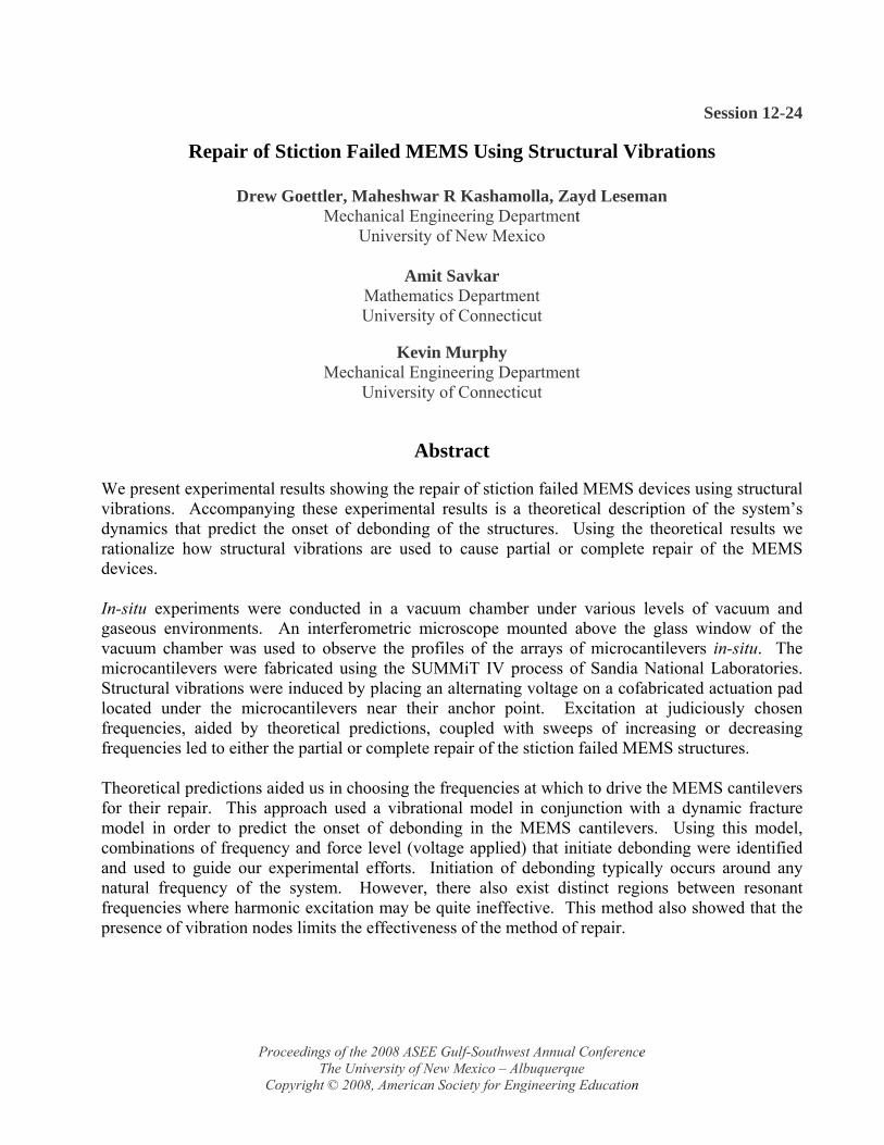
Initial proof-of-concept experiments were performed to show the viability of the method to repair stiction failed devices. Specifically, experiments were performed on idealized cantilevered beam structures as shown in Figure 1.
Figure 1. Schematic of a stiction failed micro-cantilever with an actuation pad near its base. An AC signal applied between the base and pad causes structural vibrations that induce repair of stiction failed MEMS (see Figure 2 below).
Proceedings of the 2008 ASEE Gulf-Southwest Annual Conference The University of New Mexico – Albuquerque
Copyright © 2008, American Society for Engineering Education
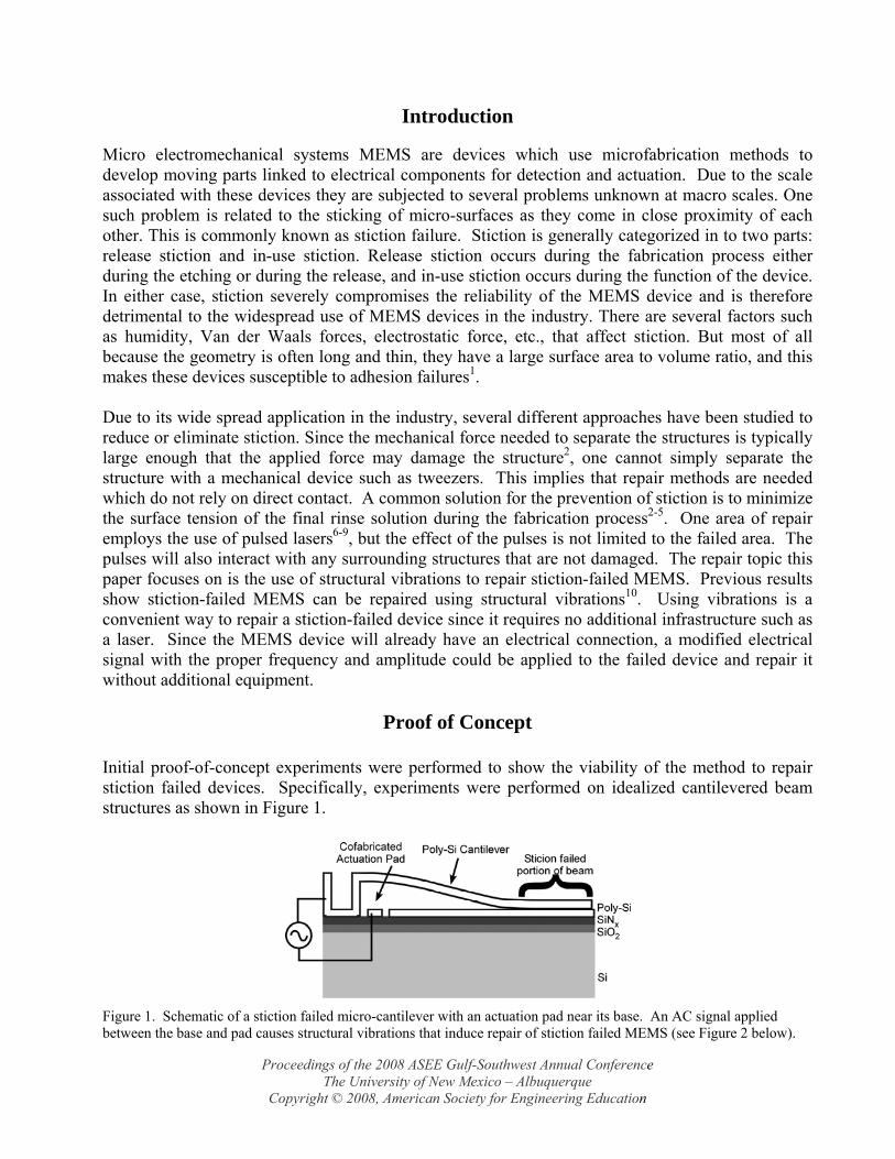
An AC signal was applied between the actuation pad and the cantilevered beam. Dynamic excitation of the beams caused full repair of some of the beams (Figure 2). These initial results, which were performed in atmosphere, are more fully detailed in Reference10. In the present work we more thoroughly characterize our idealized cantilevered beam and further develop our theoretical model to predict stiction repair of these stiction failed structures.
Figure 2. The above figures are of the same set of beams. (a) Beams 1, 2, and 3 are failed in an arc-shaped manner. (b) Beam 3 has been fully repaired by applying 220 Vpp to the actuation pad (beams are grounded), thus oscillating the beam and fully releasing it from the substrate. The frequencies applied ranged from 2.6 to 400 kHz.
Experimental Setup
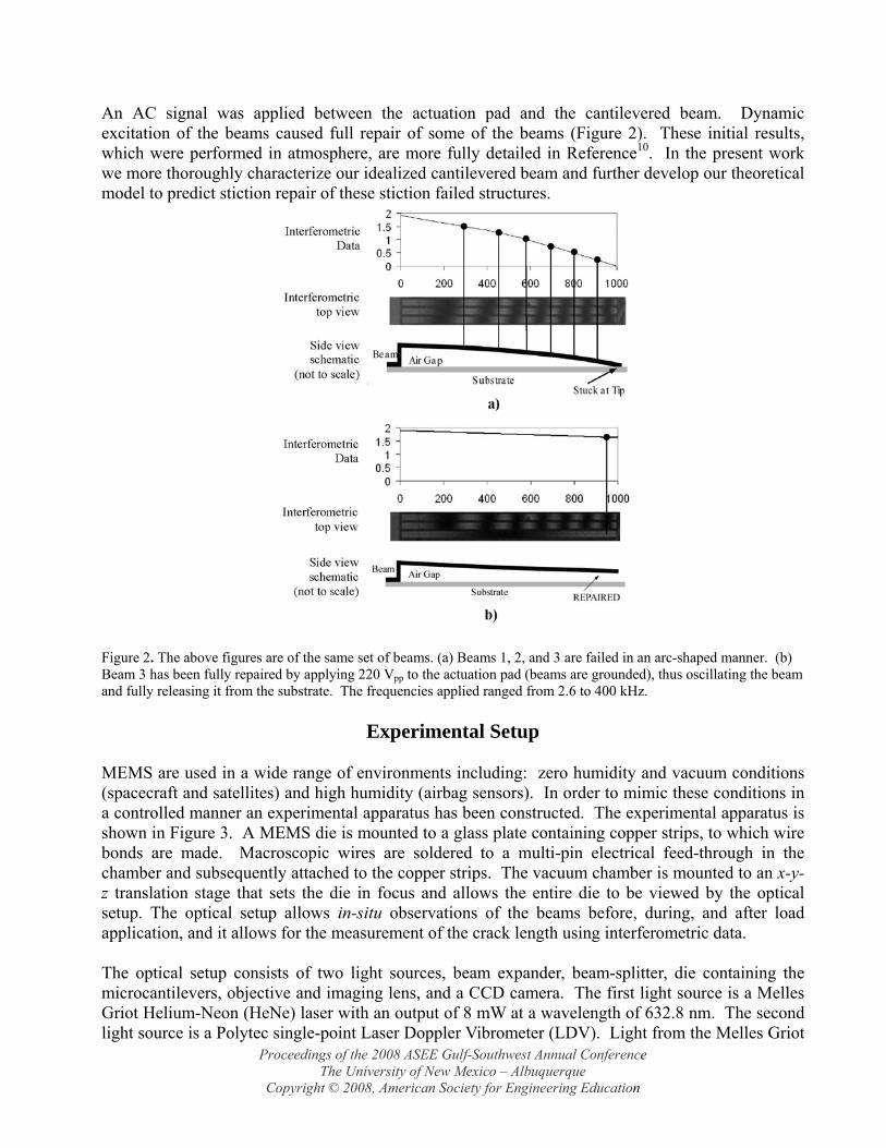
MEMS are used in a wide range of environments including: zero humidity and vacuum conditions (spacecraft and satellites) and high humidity (airbag sensors). In order to mimic these conditions in a controlled manner an experimental apparatus has been constructed. The experimental apparatus is shown in Figure 3. A MEMS die is mounted to a glass plate containing copper strips, to which wire bonds are made. Macroscopic wires are soldered to a multi-pin electrical feed-through in the chamber and subsequently attached to the copper strips. The vacuum chamber is mounted to an x-y-z translation stage that sets the die in focus and allows the entire die to be viewed by the optical setup. The optical setup allows in-situ observations of the beams before, during, and after load application, and it allows for the measurement of the crack length using interferometric data. The optical setup consists of two light sources, beam expander, beam-splitter, die containing the microcantilevers, objective and imaging lens, and a CCD camera. The first light source is a Melles Griot Helium-Neon (HeNe) laser with an output of 8 mW at a wavelength of 632.8 nm. The second light source is a Polytec single-point Laser Doppler Vibrometer (LDV). Light from the Melles Griot
Proceedings of the 2008 ASEE Gulf-Southwest Annual Conference The University of New Mexico – Albuquerque
Copyright © 2008, American Society for Engineering Education
laser passes through an 8x beam expander before passing through a beam-splitter, but the LDV laser is placed in front of the beam expander so it proceeds directly to the beamsplitter. Only one light source at a time is used. The beam-splitter is a 50/50 reflection/transmission pellicle beam-splitter with a thickness of 2 μm. Half of the light is directed towards the MEMS die. Between the die and the beam-splitter is a transparent window, which allows observation of the die while at the same time allowing the die to be at vacuum pressures. The window is a 5 mm thick anti-reflective (AR) coated piece of fused-silica 50 mm in diameter with a flatness of 1/10 λ. Light reflects off the die, passes through the beam-splitter a second time, and then enters the objective and imaging lens before coming to the CCD camera, which is used to record the data. The objective and imaging lenses act as a compound microscope. The interferometric image created by the optical setup provides a known distance of 316.4 nm between two consecutive fringes. The interferometric data is used to determine the crack length, ‘s’ of a beam.
Amplifier Function Generator Output Curve
Oscilloscope
CCD Camera
HeNe laser Laser Doppler Vibrometer
(LDV)
Vacuum Pump Isolation
Table
Figure 3. The apparatus is capable of testing MEMS devices from atmospheric pressure to 10-4 Torr in a dry N2 environment. Additionally, humid conditions can be introduced. In-situ experiments are carried out under an interferometric microscope that discerns the profile / displacements of the beams, actuators, and gears. Vibrational energy is supplied by the function generator and amplifier.
Proceedings of the 2008 ASEE Gulf-Southwest Annual Conference The University of New Mexico – Albuquerque
Copyright © 2008, American Society for Engineering Education
Electrical connections are made between the custom built amplifier and the vacuum feed-throughs. A function generator determines the input pulse/periodic signal sent to the MEMS and an oscilloscope allows for the monitoring of the output from the amplifier. Peak-to-peak voltage ranges are shown in the inset of Figure 3. A vacuum line is attached to the vacuum chamber as well as a pressure gage. The mechanical pump allows for a high vacuum state (10-4 Torr) to be reached. An N2 cylinder connected to the vacuum chamber via a needle valve allows for a controlled increase to the chamber pressure. Addition of a flask of de-ionized water through which air is bubbled through and a hygrometer (not shown) allows for humidity controlled experiments. All of the MEMS devices for this experiment were fabricated at Sandia National Laboratories using the 4-layer, SUMMiT technology11. The sacrifical oxide and structural layers in the micromachining process are tetraethylorthosilicate (TEOS) and n-type polycrystalline silicon (polysilicon) doped with phosphine gas, respectively. For the experiments described in this paper, only microcantilever beams 1500 μm long, 30 μm wide, and 2.6 μm thick are used. All of the beams are 1.9 μm above the substrate (assuming no stiction failure). A simple schematic of the SUMMiT IV microcantilevers is shown in Figure 1. Located near the fixed end of the cantilever is the actuation pad. The AC and DC electrical signal is applied between this actuation pad and the cantilever beam. The reason for applying the force at this location this is two-fold. The applied force is gap-dependent, and the placement of the actuation pad near the fixed end keeps the gap relatively constant. The second reason is that the location of the actuation pad is fixed during the fabrication process. The apparatus described above allows for the experimental characterization of the dynamic behavior of important MEMS structures under vastly different environments, but in order to fully model their behavior another important preliminary experiment must be conducted. In order to properly model the dynamic behavior of MEMS, their mechanical material properties must be known. The two main properties that must be determined are the elastic modulus and the structural damping. The natural frequencies of the microcantilever beams are also needed, but this information is used so that the material properties can be determined. Many references are available for the elastic modulus of poly-Si 12-14, but structural damping properties are not well characterized. Therefore, the previously described vacuum chamber will be employed in conjunction with a Laser Doppler Vibrometer (LDV) in order to determine the mechanical damping properties of our MEMS structures. In a high vacuum, the exponential decay curves of ideal MEMS structures’ (such as cantilevered beams) are measured and processed for determination of the mechanical dampening of the poly-Si.
Proceedings of the 2008 ASEE Gulf-Southwest Annual Conference The University of New Mexico – Albuquerque
Copyright © 2008, American Society for Engineering Education
The experimental setup to determine the material properties used the setup shown in Figure 3. Instead of using the HeNe laser as a light source, though, the head of the LDV was inserted into the optical path after the 8x beam expander but before the 50/50 beamsplittler. With the LDV, displacement data of the tip of the microcantilever beam was acquired. During the course of this research, a free response of the microcantilever beams was used to determine the damping ratio while forced vibrations were used to determine the natural frequencies of the microcantilever beams. An applied voltage of 37 VDC, which brought the tip of the 1500 μm beam nearly into contact with the substrate below, was used to observe the free response of the microcantilever. The forced vibration was a sine sweep at an amplitude of 5 V for a period of 2 sec. A voltage signal from the

LDV, corresponding to the displacement of the beam, was transferred to MATLAB® for data reduction. Using the data from the free response, the peak point of each oscillation was extracted from the raw data (Figure 4).
Figure 4. Displacement of the tip of a beam 1500 μm long at P = 42 mTorr. The blue dot indicates the peak value of
each oscillation. Displacement was sampled at 800 kHz.
A curve with the form of w(t) =αe−ζω nt (1)
was fitted to the peak points (Figure 4), and values for the α and ζωn terms are calculated. Using the ζωn value and the natural frequency of the first mode, ωn, determined by the PSD, the damping of the beam at each pressure was determined. Synchronization of the input voltage/force with the LDV along with data acquisition is accomplished by LabView software. With the LDV pointed at the tip of a 1500 μm long free-standing beam, a 5V rising edge signal was sent by LabView to the function generator, and a voltage of 80 V is applied for 300 msec. When the beam is initially pulled down, it oscillates approximately 125 msec before coming to an equilibrium position. To ensure there is no more ringing in the beam, it is held down an additional 200 msec before removing the voltage. Once the voltage is removed the cantilever beam oscillates approx. 170 msec before coming to its resting position. By setting the sampling rate of the LDV to 800 kHz for 0.5 sec, there is a high probability the LDV will sample the maximum (and minimum) deflection point of the beam over each period.
Modeling
Recently it has been shown that structural vibrations can be used to de-stick the stiction failed micro cantilever beams. The means to excite these beams play an important role in the underlying phenomenon for desticking. For example it has been shown that using mechanical loading at near resonance frequencies result in the repair of these stiction failed beams. The fundamental mechanism involved in this process is the resonance effect. While mechanical loading establishes
Proceedings of the 2008 ASEE Gulf-Southwest Annual Conference The University of New Mexico – Albuquerque
Copyright © 2008, American Society for Engineering Education

the fact that indeed the structural vibrations can be used to de-stick stiction failed beams, it is more natural to look at electrical in-situ capabilities for exciting the beams as means of stiction repair. Electrical excitation poses a significantly different mechanism of stiction repair through structural vibrations. This is primarily due to the fact that the electrical loading is gap dependent. This loading is similar to the gap dependent loading in a parallel plate capacitor model. The primary governing equation is given by,
),(, txFEIWWcWm xxxx =++ &&& (2) where the right hand side is the electrical force represented by,
Fe (x, t) = εArea2
V 2(t)δ −W (x, t)[ ]2 H x − x1( )− H x − x2( )[ ] (3)
It can be observed that the gap dependent term in the forcing function plays an important role in dictating the characteristics of the governing equation. Expressing the gap dependent loading term in terms of binomial expansion, along with a galerikin discretization of displacements where A is the modal amplitude, we obtain ordinary differential equations with periodic coefficients given by
[ ]a
AaAA )cos()()cos()()( τεττεετμτ =++++ &&& (4)
where, ε, μ and a are called the Mathieu constants. A general relationship of each of the Mathieu parameters is as follows:
20aVε κ= − (5)
0 3
ak
κ εδ
= (6)
2
14
ar
= (7)
Note: ε0 is the permittivity of air, and r is the frequency ratio, Ω/ωn. ε, μ, and a have physical quantities such as the mass, the damping constant, EI, etc. respectively embedded in them. In general it has been seen in the past that these types of equations have stability characteristics that describe the system, which can lead to unbounded amplitudes. A regular perturbation method is used to obtain the solution equation (4). The solution procedure renders an expression for a=a(ε) for different cases of n. A complete description of n can be found in reference 15. These functions describe combinations of (a, ε) that lead to periodic solutions, indicating a stability boundary. These functions are explicitly given by
2
2a εε= − − (8)
2
2 21 114 2
a8εε μ ε
ε⎛ ⎞= − ± − −⎜ ⎟⎝ ⎠
(9)
Proceedings of the 2008 ASEE Gulf-Southwest Annual Conference The University of New Mexico – Albuquerque
Copyright © 2008, American Society for Engineering Education
2 22
1 11 16 4
a 26ε ε με
⎛ ⎞= − + ± −⎜ ⎟⎝ ⎠
ε (10)
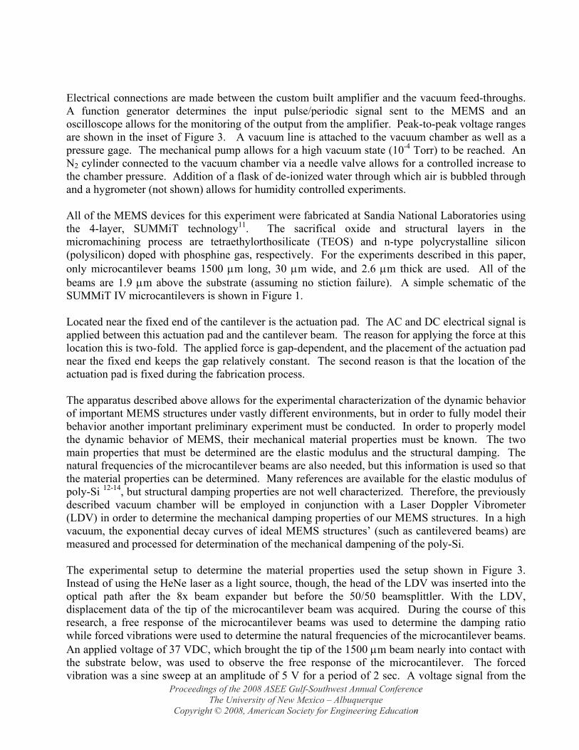
These equations are plotted in Figure 5 for the cases of ζ = 0, 0.25. The effect of damping on the stability of the system is such that, the system is more stable with higher damping. This translates as having more stable zones (un-shaded region) in Figure 5. An unstable region is associated with an unbounded (large amplitude) response to the electrical excitation of the beam. A large amplitude behavior will result in de-sticking of the beam from the substrate. Thus a higher damping value directly reduces the possibility of having unstable zones, which means fewer regions of large amplitude, which affects the de-sticking process adversely.
Figure 5. Plot of Mathieu constants, a and ε, for multiple values of n.
In Figure 5 the leftmost curve corresponds to n=0, and is independent of damping. The next two curves (from the left) that cross the ε = 0, axis are related to the undamped n=1 case. The damped n =1 case is moved up off the axis and is rounded near the vertex. The unstable region is shaded and clearly indicates parameter combinations that lead to unbounded solutions. Additional cases are shown and progress to the right as n increases. These curves are reminiscent of those corresponding to the standard form in Mathieu’s equation.
Results
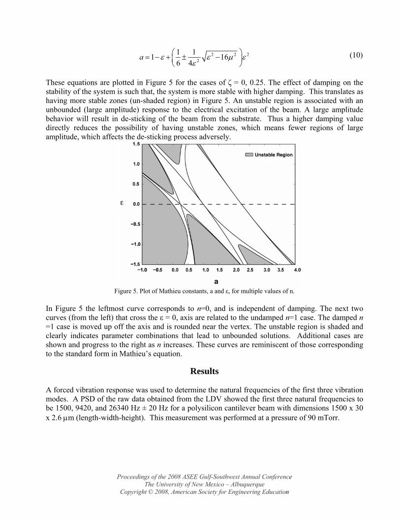
A forced vibration response was used to determine the natural frequencies of the first three vibration modes. A PSD of the raw data obtained from the LDV showed the first three natural frequencies to be 1500, 9420, and 26340 Hz ± 20 Hz for a polysilicon cantilever beam with dimensions 1500 x 30 x 2.6 μm (length-width-height). This measurement was performed at a pressure of 90 mTorr.
Proceedings of the 2008 ASEE Gulf-Southwest Annual Conference The University of New Mexico – Albuquerque
Copyright © 2008, American Society for Engineering Education
Once the natural frequencies of the first three modes were determined, an experimental value of Young’s Modulus for polysilicon could be calculated. Using the equation for the natural frequency of the ith mode of a cantilever beam 16
fi =EIρA
kil( )2
2πl2 (11)
and then solving for E gives
( )
2
2
22⎥⎥⎦
⎤
⎢⎢⎣
⎡=
lkfl
IAE
i
iπρ (12)
Using the first three frequencies, a mean value for the elastic modulus, E, of polysilicon was calculated to be 151 GPa. Published experimental results for Young’s Modulus for polysilicon range between 140 and 169 GPa 12-14.
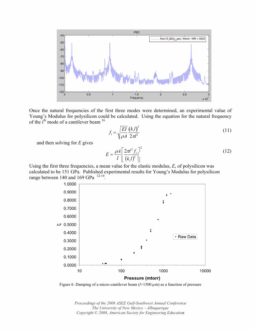
Figure 6. Damping of a micro-cantilever beam (l=1500 μm) as a function of pressure
Proceedings of the 2008 ASEE Gulf-Southwest Annual Conference The University of New Mexico – Albuquerque
Copyright © 2008, American Society for Engineering Education
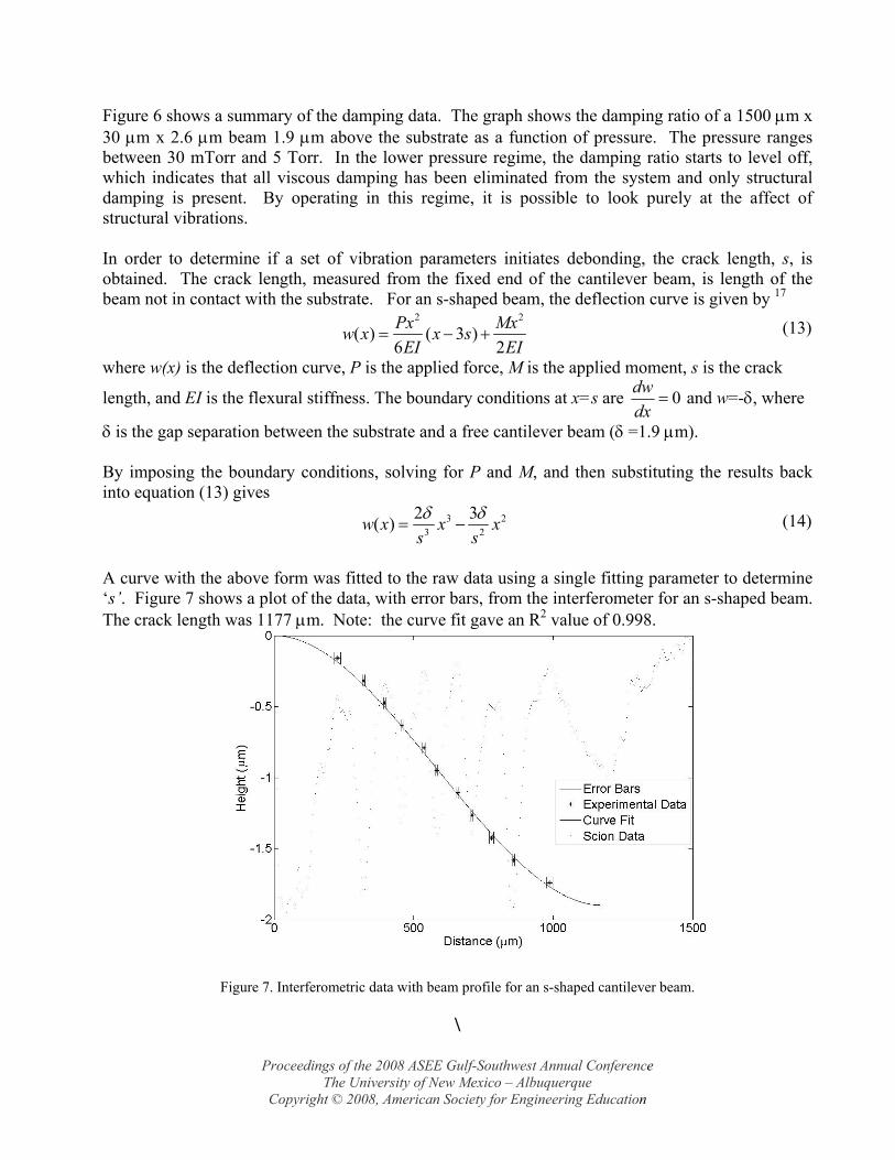
Figure 6 shows a summary of the damping data. The graph shows the damping ratio of a 1500 μm x 30 μm x 2.6 μm beam 1.9 μm above the substrate as a function of pressure. The pressure ranges between 30 mTorr and 5 Torr. In the lower pressure regime, the damping ratio starts to level off, which indicates that all viscous damping has been eliminated from the system and only structural damping is present. By operating in this regime, it is possible to look purely at the affect of structural vibrations. In order to determine if a set of vibration parameters initiates debonding, the crack length, s, is obtained. The crack length, measured from the fixed end of the cantilever beam, is length of the beam not in contact with the substrate. For an s-shaped beam, the deflection curve is given by 17
2 2
( ) ( 3 )6 2Px Mxw x x sEI EI
= − + (13)
where w(x) is the deflection curve, P is the applied force, M is the applied moment, s is the crack
length, and EI is the flexural stiffness. The boundary conditions at x=s are dwdx
= 0 and w=-δ, where
δ is the gap separation between the substrate and a free cantilever beam (δ =1.9 μm). By imposing the boundary conditions, solving for P and M, and then substituting the results back into equation (13) gives
3 23 2
2 3( )w x x xs sδ δ
= − (14)
A curve with the above form was fitted to the raw data using a single fitting parameter to determine ‘s’. Figure 7 shows a plot of the data, with error bars, from the interferometer for an s-shaped beam. The crack length was 1177 μm. Note: the curve fit gave an R2 value of 0.998.
Figure 7. Interferometric data with beam profile for an s-shaped cantilever beam. \
Proceedings of the 2008 ASEE Gulf-Southwest Annual Conference The University of New Mexico – Albuquerque
Copyright © 2008, American Society for Engineering Education
Summary This paper describes an experimental setup capable of obtaining stiction-repair parameters and characterization parameters for MEMS devices. Using this setup, an elastic modulus of 151 GPa and a plot of damping ratios was measured. Along with these parameters, the initial crack length for a particular beam can easily be measured. By varying the environmental conditions, the parameters used in modeling can be determined with the current setup. The next step is to validate the model which predicts the initiation of debonding. Using the current setup to apply various frequency and voltage parameters to the microcanilever beams, a map of the instability regions will be traced.
References 1. Abe, T., W. Messner, and M. Reed. Effective Methods to Prevent Stiction During Post-Release-Etch
Processing. in Proceedings of IEEE Micro Electro Mechanical Systems Conference. 1995. Amsterdam, Netherlands.
2. Madou, M.J., Fundamentals of Microfabrication: The Science of Miniaturization. 2nd ed. 2002, Boca Raton, FL: CRC Press LLC.
3. Ashurst, W.R., et al., Alkene Based Monolayer Films as Anti-Stiction Coatings for Polysilicon MEMS. Sensors Actuators A, Physics, 2001. 91(3): p. 239-248.
4. Fujitsuka, N. and J. Sakata, A New Processing Technique to Prevent Stiction Using Silicon Selective Etching for SOI-MEMS. Sensors Actuators A, Physics, 2002. 97-98: p. 716-719.
5. Mulhern, G.T., D.S. Soanne, and R.T. Howe, Supercritical Carbon Dioxide Drying of Microstructures, in Transducers '93; 7th International Conference on Solid-State Sensors and Actuators. 1993: Pacifico, Yoko. p. 296-299.
6. Phinney, L.M. and J.W. Rogers, Pulsed Laser Repair of Adhered, Surface-Micromachined, Polycrystalline Silicon Cantilevers. Journal of Adhesion Science Technology, 2003. 17: p. 603-622.
7. Rogers, J.W. and L.M.Phinney, Process Yields for Laser Repair of Aged Stiction-failed MEMS devices. JOURNAL OF MICROELECTROMECHANICAL SYSTEMS, 2001. 10: p. 280-285.
8. Rogers, J.W. and L.M. Phinney, Nanoscale Laser Repair of Adhered MEMS Structures. Journal of Heat Transfer, 2002. 124: p. 394-396.
9. Rogers, J.W., T.J.Mackin, and L.M. Phinney, A Thermomechanical Model for Adhesion Reduction of MEMS Cantilevers. JOURNAL OF MICROELECTROMECHANICAL SYSTEMS, 2002. 11: p. 512-520.
10. Savkar, A.A., et al., On the Use of Structural Vibrations to Release Stiction Failed MEMS. Journal of Microelectromechanical Systems, 2007. 16(1): p. 163-173.
11. Sniegowski, J.J. and M.P.d. Boer, Ic-Compatible Polysilicon Surface Micromachining. Annual Review of Material Science, 2000. 30: p. 299-333.
12. Greek, S., et al., Mechanical Characterization of Thick Polysilicon Films: Young's Modulus and Fracture Strength Evaluated with Microstructures. Journal of Micromechanical Microengineering, 1999. 9: p. 245-251.
13. Gupta, R.K., P.M. Osterberg, and S.D. Senturia, Material Property Measurements of Micromechanical Polysilicon Beams. Microlithography and Metrology in Micromachining II, 1996.
14. Maier-Schneider, D., et al., Elastic Properties and Microstructure of LPCVD Polysilicon Films. Journal of Micromechanical Microengineering, 1996. 6: p. 436-446.
15. Mook, D.T. and A.H. Nayfeh, Nonlinear Oscillations, ed. I. John Wiley & Sons. 1995, New York. 16. William Weaver, J., S.P. Timoshenko, and D.H. Young, Vibration Problems in Engineering. 5th ed. 1990, New
York: John Wiley & Sons, Inc. 17. Timoshenko, S. and J.M. Gere, Theory of Elastic Stability. 2nd ed. 1961, New York: McGraw-Hill. ZAYD C. LESEMAN Dr. Zayd.C.Leseman currently serves as an Assistant Professor of Mechanical Engineering Department at the University of New Mexico, Albuquerque. His research interests include design, fabrication and analysis of novel MEMS/NEMS devices and experiments in order to study the surface, mechanical, and electrical properties of materials at the nanoscale. Additionally, he creates bioMEMS devices to perform studies in single-cell mechanics and nano/microfluidics.
Proceedings of the 2008 ASEE Gulf-Southwest Annual Conference The University of New Mexico – Albuquerque
Copyright © 2008, American Society for Engineering Education
AMIT SAVKAR Dr. Amit Savkar currently serves as an Assistant Professor of Mathematics Department at the University of Connecticut, Storrs.His research interests include the applications of vibrations and fracture mechanics to MEMS. He has been working on the stiction repair process of MEMS cantilever beams using vibrations.
KEVIN MURPHY Dr. Kevin Murphy currently serves as an Associate Professor in the Department of Mechanical Engineering at the University of Connecticut, Storrs. His research interests include nonlinear dynamics, vibrations, stability and solid mechanics.
DREW GOETTLER Drew Goettler is a Graduate student of Mechanical Engineering Department at the University of New Mexico, Albuquerque.His research interests include Microelectromechanical systems (MEMS) .His current research concentrates on repair of stiction failed MEMS by using the structural vibrations. He was awarded as the best graduate teaching assistant for the year 2007, school of engineering at the University of New Mexico. MAHESHWAR REDDY KASHAMOLLA Maheshwar R.Kashamolla received the B.Tech degree from P.Indra Reddy Memorial Engineering College, Jawaharlal Nehru Technological University, India. He is currently working towards the Master’s degree in the Department of Mechanical Engineering at the University of New Mexico, Albuquerque. His research interests are in the area of Microelectromechanical systems (MEMS). He is currently working on prevention of stiction failure in MEMS/NEMS.
Proceedings of the 2008 ASEE Gulf-Southwest Annual Conference The University of New Mexico – Albuquerque
Copyright © 2008, American Society for Engineering Education
Related Documents