H I G HWAYS AGENCY TRL Limited Library L-o~.~ c-c2~( Repair of concrete in highway bridges - a practical guide by S Pearson (Derbyshire County Council) and R G Patel (TRL Limited) Application Guide AG43

Welcome message from author
This document is posted to help you gain knowledge. Please leave a comment to let me know what you think about it! Share it to your friends and learn new things together.
Transcript
H I G H W A Y S A G E N C Y
TRL Limited
Library L-o~.~ c-c2~(
Repair of concrete in highway bridges - a practical guide
by S Pearson (Derbyshire County Council) and R G Patel (TRL Limited)
Application Guide AG43

Repair of concrete in highway bridges - a practical guide
Prepared for Quality Services, Civil Engineering, Highways
Agency and CSS Working Party for Highway Research
S Pearson (Derbyshire County Council) and R G Patel (TRL Limited)
Application Guide AG43

Fi~t Published 2002 ISSN 0968-4107 Copydgh t T R L L i m i t e d 2002.
This report has been produced by TRL Limited, under/as part of a contract placed by the Highways Agency and CSS. Any views expressed in it are not necessarily those of the Agency or the CSS.
TRL is committed to optimising energy efficiency, reducing waste and promoting recycling and re-use. In support of these environmental goals, this report has been printed on recycled paper, comprising 100% post-consumer waste, manufactured using a TCF (totally chlorine free) process.
ii

Members of the Working Group
Mr S Pearson
Mr N Burrows
Mr J Chrimes
Mr G Cole
Mr J Cuningharne
Mr N Loudon
Mr B Mawson
Dr R Patel
Mr D Sharpe
Prof. P Vassie
Mr L Wellappili
Derbyshire County Council (Chairman)
Suffolk County Council
Cheshire County Council
Surrey County Council
TRL Limited (part-time)
Highways Agency
Gwent Consultancy
TRL (Secretary)
Glasgow City Council
TRL Limited
Highways Agency (part-time)
iii

CONTENTS
Page
EXECUTIVE SUMMARY
1 INTRODUCTION
1.1 History of concrete with steel
1.2 Bridges - Design life
1.3 Durability/Service problems
1.4 Number of bridges/Repair costs
1.5 Modem trends in traffic flow/Load can2cing capacity
1.6 Future developments
1.7 Objectives
2 CAUSES OF DETERIORATION OF CONCRETE BRIDGES
2.1 Reinforcement corrosion
2.2 Alkali silica reaction
2.3 Freeze-thaw attack
2.4 Sulfate attack
2.5 Plastic settlement and early thermal cracks
2.6 Factors affecting concrete deterioration
3 INSPECTION
5
5
6
6
6
7
8
8
9
9
10
10
13
14
14
17
4 INVESTIGATION
4.1 Overview of investigation
4.2 Non-destmctive testing
4.3 Semi-destructive tests
4.4 Structural assessment
5 REVIEW AND ASSESSMENT
5.1 Introduction
5.2 Remedial techniques for structures vulnerable to reinforcement corrosion
6 DECIDE THE COURSE OF ACTION
6.1 Selecting the best option
6.2 Management issues
23
23
24
25
26
29
29
32
37
39
41

7 NON CONCRETE REPAIR OPTIONS
7.1 Introduction
7.2 Surface treatments
7.3 Cathodic protection (CP)
7.4 Chloride extraction
7.5 Realkalisation
7.6 Strengthening using plate bonding techniques
7.7 Comparison of repair methods
8 CONCRETE REPAIR
8.1 Introduction
8.2 Select repair material
8.3 Material properties
8.4 Structural considerations
8.5 Breaking out of concrete
8.6 Reinforcements
8.7 Concrete repair methods
8.8 Crack sealing
8.9 Design and specification
8.10 Design and specify - ralevant aspects
8.11 Supervision/inspection
8.12 Trials
8.13 Site control and restrictions
8.14 Installation
8.15 Strength and propping
8.16 Contractual arrangements
8.17 Records
8.18 Monitoring the performance of repairs
8.19 Concrete repair check list
9 ACKNOWLEDGEMENTS
10 REFERENCES
11 GLOSSARY
APPENDIX: STANDARD AND ADVICE NOTE RELEVANT TO CONCRETE BRIDGE REPAIR
Page
47
47
47
49
52
54
55
56
59
59
60
62
63
64
65
66
70
72
73
73
73
73
74
74
74
75
75
75
79
81
89
91
vi
Repair o f concrete in highway bridges - a practical guide
EXECUTIVE SUMMARY
This practical guide covers all aspects of concrete bridge repair in sufficient depth to implement a best value option. It is designed and written for readers who are new to the field and wish to become familiar with the processes involved in a bridge repair starting with inspection through carrying out remedial work and monitoring the repair. Deciding the course of action for a particular structure includes several key stages at which alternative options should be considered. This is done through an easy to follow flow chart. This is followed by non-concrete repair options (such as surface treatments, cathodic protection, chloride extraction and realkalisation) and concrete repair options (such as patch repair with mortar, concrete, flowable concrete, sprayed concrete).
The various sections are set out in a logical order, and provide relevant information on best repair practice. For those needing more details on any subject, technique or protocols, references are provided. Hence, the guide will also be useful to practising engineers, bridge owners and contractors involved in the repair of concrete bridges. Experience has been drawn from engineers specialising in the maintenance and management of Highways Authority owned structures but the contents of this guide are applicable to concrete bridge structures owned by other organisations.
Reinforced concrete has been used for construction of bridges since the early 20 ~h century. Concrete was initially regarded as a maintenance free material. However, for a variety of reasons, particularly the ever-changing environment and aggressive service conditions under which bridges have to operate, they are susceptible to deterioration. The long, 120 year design life, demands properly designed concrete, attention to detailing, careful supervision and a high standard of workmanship during construction.
The mechanisms causing deterioration in concrete bridges are numerous. Two of the most common causes of deterioration are due to chloride penetration and carbonation of concrete leading to pitting and general corrosion of steel respectively. Corrosion of steel results in cracking and spalling of the concrete and this in turn leads to secondary damage caused by enhanced ingress of aggressive agents. If a risk of reinforcement corrosion is detected early during routine inspection, damage can be avoided or reduced significantly by relatively simple protective measures. On the other hand, if corrosion of the reinforcement has proceeded to the point where it has caused cracking and spalling of the concrete, repair measures are normally more complicated and expensive. This is true irrespective of the deterioration mechanism. If repair of a damaged bridge is not implemented at the earliest opportunity, the consequences could be far reaching, particularly if the structural properties of the bridge are impaired. To repair deteriorated structures a systematic approach is necessary with a balance between technology, management and economics.
With the objective of producing a practical guide for the repair of bridges, Highways Agency funded a contract with TRL. A working group was formed to steer the project. It comprised of Bridge Engineers and Material Scientists from the CSS (formerly the County Surveyors' Society), HA and TRL. Relevant topics for concrete bridge repair were identified and discussed, and each member provided a written contribution for the Guide. Many local authority Bridge Engineers contributed to the Guide by hosting visits, taking part in discussions, and answering questionnaires.
The aim of the Guide is to provide practical guidance to improve repair of concrete bridges so that they meet their functional requirements throughout their design life. The 'added value' of this Guide is that it covers all aspects of concrete bridge repair in a single document and in sufficient depth to enable a maintenance engineer to produce a 'best value' repair solution.
When a bridge shows signs of deterioration, the repair strategy should consider the following steps:
• Investigation and diagnosis.
• Assess the extent, significance and severity of the damage (including the effect on structural capacity).
Version No: 1 Application Guide AG43 August 2002
Repair o f concrete in highway bridges - a practical guide
• Define the objective and constraints of repairs.
• Prepare a repair strategy and determine viable options.
• Carry out whole life costing.
• Select a repair method.
• Selection of materials.
• Prepare specification for repair.
• Surface preparation.
• Carry out repairs.
• Record repairs.
• Monitor repairs.
The Guide includes all aspects of concrete bridge repair, starting with the concrete deterioration mechanism and the inspection of bridges through to carrying out remedial work and monitoring the repairs.
A brief introduction to issues related concrete bridge repair is given in Section 1 and the causes of deterioration of reinforced concrete are discussed in Section 2.
Regular and thorough inspection is the primary source of information on the condition of the bridge stock, and is essential for effective bridge management. Most bridge owners follow an inspection regime very similar to that specified by the Highways Agency's 'Bridge Inspection Manual' and Departmental Standard BD63. Section 3 of this Guide deals with general and principal inspections of concrete bridges. It describes how and what types of visual defects may be observed. It also includes a brief description of techniques used to investigate non-visible damage.
When a structure shows signs of distress or deterioration a thorough investigation will be necessary to determine canse(s), extent and rate of deterioration and may include an assessment of structural properties. Section 4 deals with the testing of reinforced concrete and structural assessment. Concrete testing described in Section 2, which forms a part of a special inspection carded out on 'as required' basis, is triggered by the routine inspection. Any remedial work done without the investigation described in this Section could limit the long-term durability of the repair.
Remedial techniques for structures vulnerable to reinforcement corrosion are described in Section 5. This includes preventive measures to stop or delay the initiation of the corrosion process.
Deciding the course of action for a particular structure includes several key stages at which altemative options should be considered; this may include taking no further action, installation of a monitoring system or application a weight restriction. The crucial decision as to how the structure is managed should be taken after the possible maintenance options have been assessed and a whole life costing carried out. The decision making process is given in Section 6. It includes the management issues which must be addressed before taking any decision on the repair.
As an alternative to conventional repair, a number of options not based on concrete replacement could be effective in certain situations. These are largely surface treatments such as coatings, silane treatment and corrosion inhibitors, or electrochemical treatments such as cathodic protection, chloride extraction and realkalisation. Their main objective is to reduce the rate of steel corrosion, a major contributor to the deterioration of steel reinforced concrete. These are described in detail in Section 7.
Version No: 1
2
Application Guide AG43 August 2002
Repair o f concrete in highway bridges - a practical guide
The selection of a repair strategy and materials is one of the most important steps in the repair and rehabilitation programme. A variety of repair processes, a large number of proprietary products and a range of traditional cementitious materials make the selection process extremely difficult even before economic and technical considerations are taken into account. Section 8 starts by defining repair material requirements including their mechanical properties and long-term durability. It discusses all the available repair methods, their selection criteria, and the design and specification of the repair. Other factors that are integrally linked to the completion of a satisfactory repair such as trials, installation of the repair, site constraints, propping of the structure and contractual arrangements are also discussed. It is vital that for future reference 'as repaired' records of the entire repair are kept. A sample of a proforrna record sheet is included in Section 8. The Section also discusses objectives and provides a strategy for monitoring the repair.
During the course of writing of this Guide it became clear that there are several areas where further research would be beneficiai. Two areas identified were electro-osmosis and anti-carbonation coatings. Most deterioration mechanisms in concrete involve water. Electro-osmosis offers a potential technique for reducing the moisture level in concrete and research is required to evaluate the effectiveness of the technique. Anti-carbonation coatings are normally applied to structures that have been treated using the realkalisation technique. However, it has been reported that these coatings debond after a short period. It has been suggested that this may be because they are applied before the concrete has had time to dry out and that research to determine the optimum time to apply the coating would be useful. It is anticipated that as more research is carried out some of these gaps in our knowledge will be filled and the Guide will be updated accordingly.
Version No: 1 Application Guide AG43 August 2002
3
Repair o f concrete in highway bridges - a practical guide
1 INTRODUCTION
1.1 History of concrete with steel
One of the early pioneers of reinforced concrete was Francois Hennebique, who obtained patents for reinforced concrete (RC) beams and established his design and build operation from Paris in 1898. The spread of RC technology occurred through the use of agents resident in various countries around the world, who would oversee the production of scheme plans which were sent to Paris for detailed design and production of drawings for construction.
In Britain, Hennebique's agent was Louis Gustave Mouchel, who established his office in Swansea following construction of the first RC framed building there between 1897-99 and then turned his attention to the promotion of RC construction, taking out further patents to protect his market position. The conflict between the determination to promote RC technology and the desire to maintain commercial advantage, was probably responsible for the slow acceptance of reinforced concrete in Britain. Elsewhere, the success of RC construction was prodigious with 20,000 structures built by 1911, doubling to 40,000 by 1920. By comparison, only 1000 structures had been built in Britain by 1911 and this had increased only to 3000 by 1920. The 'Heunebique System for Ferro Concrete Construction' was very much the only system used in the early decades of the 20 'h century.
Hennebique was aware of the importance of the methods of making and placing concrete. To begin with, he personally selected and trained the men to be entrusted with his method of construction before they were issued with a licence to use his patents. In the days before mechanical control of mix proportions and particularly mechanical vibration, the prime importance of constant supervisory control was recognised. These principles are no less true today when Engineers automatically assess exposed concrete for quality of finish, joint preparation and uniformity of pour control. Although a great deal more is now known about the behaviour of concrete and the requirements needed to achieve particular characteristics, the basic ingredients to give strength, density, impermeability and fire resistance are unchanged. It was known that chlorides (sea water) should be excluded and that strength was affected by aggregate types and water/cement ratio. Ahead lay the problems of high-alumina cement, alkali-silica reaction, sulfate attack and awareness of the effects of carbonation and of chloride ingress in hardened concrete from chlorides (e.g. de-icing salts).
The major developments in reinforced concrete which have affected design since Hennebique's day are the introduction of high tensile steel and prestressing techniques which have improved load carrying and span characteristics of concrete structures. Eugene Freysinnet pioneered the use of prestressing systems in France in the 1930s. Prior to the Second World War, most of the developments in prestressed concrete took place in continental Europe and it was only with the influx of refugee European engineers in the pre-war years, that detailed knowledge of prestressing became available in Britain. L.G. Mouchel & Partners were responsible for some of the early designs based on design work undertaken for a military underground storage system near Bath using pre-tensioned steel. They went on to develop a method of producing pre-tensioned concrete railway sleepers for the Ministry of Works to combat the wartime shortage of timber. This work led to the establishment of a factory at Tallington, Lincolnshire in 1943 by Dow Mac Ltd.
The shortage of steel in the post war years, provided a continuing incentive for the use of RC and prestressed concrete and again the Ministry of Works encouraged its introduction. At this time there were no British post-tensioning systems and the choice lay between the Freysinnet system and the Magnel-Blaton system devised by Gustave Magnel in Belgium during the Second World War. The first post-tensioned bridge built in England was Nurm's Bridge in Lincolnshire which was built in 1947 with a span of 22.5m. A number of bridges were built over the next few years using prestressing systems developed in Britain such as the Lee-McCall and Gifford-UdalI systems as well as those imported from the continent such as the Freysinnet and Magnel systems. Although methods of prestressing developed significantly in the 1950s and 1960s, it was not until the 1980s that the problems of inadequate grouting of post tensioned structures and protection of joints in segmental construction were realised.
Version No: 1 Application Guide AG43 August 2002

Repair o f concrete in highway bridges - a practical guide
Many of the bridge structures designed by Mouchel are still in service, particularly those built without joints, a concept ahead of its time in terms of improved durability. Where deterioration has occurred, it is often the case that concrete quality is inadequate for its environment and the application of detailing practice that would be unacceptable today. The history of performance of RC is more than 100 years, whereas prestressed concrete has only been around for a little over 50 years. The potential durability problems with prestressed/post-tensioned concrete are now well established from the findings o fHA ' s Special Inspection Programme, but in general, prestressed concrete would be expected to be more durable than RC because cracking is restricted and higher strength concrete is used.
1.2 Bridges - Design life
The requirement of BS5400, is that all bridges be designed for a life of 120 years, at the end of which they should need replacement. For concrete bridges in particular, it was for many years believed by many bridge owners and designers, that reinforced concrete did not deteriorate and that realisation of a 120 year life with little or no maintenance, was achievable. In practice, this has been shown to be wrong and many bridges have required maj or maintenance, strengthening and even early replacement as a result of deterioration. This fundamental truth has been accepted in this country and elsewhere. The concept of 'functional obsolescence', where structures require planned maintenance/upgrading during their life, until they reach a point where they need to be replaced, has been accepted practice. This concept has been included within the Highways Agency's current strategy for management of their structures and is also the objective for Local Authority Bridge owners.
1.3 Durability/Service problems
Many concrete bridges are now showing signs of deterioration and this trend can be expected to continue unless repairs and preventative measures are carried out. Much of the deterioration is attributable to chlorides from de-icing salts which penetrate the concrete and 'depassivate' the reinforcement causing corrosion. For some bridges where chloride attack is not significant, evidence of deterioration will not become apparent until carbonation is well advanced. The rate of carbonation is dependent on the quality of the concrete and is likely to take longer for modem concretes where enhanced concrete quality is assured through the application of improved specifications. Deterioration can also be due to poor design and detailing, poor materials, poor workmanship or inadequate maintenance.
In summary durability and problems in service are likely to be attributable to the adoption of inadequate practice in the following areas:
• Detailing practice i.e. depth of concrete cover to rebar, provision for dealing with leakage from joints, access for maintenance.
• Design requirements for maximum rebar spacing, type and spacing of shear links, maximum permissible crack width under service loading, provision of reinforcement to control cracking during the hydration process.
• Design strength of concrete which is influenced by the density and permeability of the hardened concrete.
1.4 Number of bridges/Repair costs
The Highways Agency is responsible for 9700 bridges and of these approximately 80% are concrete. In comparison Local Authorities including those in Scotland, Wales and Northern Ireland are collectively responsible for 80700 bridges. Regionally there are variations in the make up of the bridge stock. For example, 52% of the stock in the South East are concrete whereas this proportion reduces to 33% in the North West where the proportion of masonry arch bridges is greater. Overall for the country as a whole 38% of bridges are concrete. These figures are based on a Year 2000 Bridge census carried out by the CSS.
Version No: 1 Application Guide AG43 August 2002
6
Repair o f concrete in highway bridges - a practical guide
It would be expected that concrete bridges in the North would deteriorate faster than those in the south where winter temperatures are higher and road salting is less frequent.
Maintenance funding for all LA bridges is currently inadequate at a level of 0.32% of the replacement cost of the bridge stock. In order to achieve a 'steady state' maintenance condition, it is estimated that maintenance expenditure should be 1% of the replacement costs. The proportion of these sums required for repair of concrete bridges is difficult to quantify but it would be expected that repair schemes would be costed on a whole life basis to ensure that the repair strategy adopted is the most economic.
The Highways Agency bridge stock is statistically younger than Local Authority structures, and is generally less diverse in structural form and type, though often complex in layout. Structures on Motorways and Trunk Roads are usually subject to greater vehicle loading and traffic volumes, and consequently increased wear and tear. Difficulty of access and limitations on traffic restrictions may be significant factors in the nature, duration and cost of maintenance works undertaken, and structural concrete repairs may be combined with other bridge maintenance to meet overall network management constraints. For many years the available maintenance funding has been targeted at priority works based on a rigorous bidding system, to ensure that essential safety related maintenance is completed expeditiously, and backed up by a programme of preventative and routine works. Increasingly whole life costing and assessment techniques are being adopted, feeding into route based strategies to ensure that funds are utilised on the greatest needs, and that safety levels on individual structures and elements are not compromised.
1.5 Modern trends in traffic flow/Load carrying capacity
Increases in loading can also affect the amount of deterioration in structures, where they are experiencing service loads greater than those for which they were designed.
During the 1980s it was realised that loadings were increasing and that assumptions about the worst foreseeable loadings on bridge decks had not made adequate allowance for the densities of loading that could arise during traffic jams. This was exacerbated by the shift away from lighter goods vehicles to heavier vehicles. These vehicles had a higher gross and axle weights and at certain times of the day they could constitute a large percentage of the total number of vehicles in the traffic flow. This leads to the development of current loading standards which altow:
• A higher percentage of HGVs in traffic.
• Allowance for possible overload.
• Higher allowances for possible dynamic effects.
• Possible lateral bunching of vehicles.
Future increases in loading are likely as a result of increased volume of traffic and the possibility of the maximum allowable vehicle weight being increased above 44 tonnes.
Increases in traffic using the road network will also impact on the ability to carry out repairs safely. It is conceivable that, for heavily trafficked roads, temporary closure or even traffic restriction to carry out repairs will rarely be possible. This is a factor that should be borne in mind when developing the maintenance strategy for structures on particular routes.
Version No: 1 Application Guide AG43 August 2002
7

Repair o f concrete in highway bridges - a practical guide
1.6 Future developments
Up to now the maintenance of bridges has been hampered by the lack of a coherent strategy and has resulted in a backlog of maintenance work. In future this will be addressed for Highways Agency (HA) structures through the 'Steady State Bridge Programme', which will focus on maintaining safety, minimising expenditure over time, minimising disruption to users and minimising the impact on the environment. For Local Authorities (LAs), the backlog of maintenance work is significantly worse and has been hampered by the priority given to the National Bridge Assessment and Strengthening Programme. The extent and type of maintenance required for LA structures is also very different to that of the HA, because as discussed above there are regional variations in the mix of bridge types and the stock is much older.
It is hoped that future budgets for LA bridge maintenance will recognise the decline that has occurred and make provision for additional funding to achieve a 'steady state' maintenance condition. This objective will be greatly assisted by the development of improved repair materials and techniques. Of equal importance is the means of procurement of repair works and there could be a role for lifetime performance based criteria, with some risk transfer from the client to the contractor/supplier. The lessons leamed from the past about durability, will be of great benefit if applied to improved specifications for new works.
1.7 Objectives
Repair of concrete highway stmctures is not covered by the general requirements of the Series 1700 Structural Concrete clauses in the Specification for Highway Works. Specific guidance is currently available in BD27/86 'Materials for Repair of Concrete Highway Structures' and BA35/90 'Inspection and Repair of Concrete Highway Stmctures'. These documents are out of date. A new document for the repair of concrete highway structures is planned by the HA and will benefit from the guidance contained within this Guide.
The main objective of this Guide is to provide the necessary information starting with the concrete deterioration mechanisms and the inspection of bridges through to carrying out remedial work and monitoring the repairs. It covers all aspects of concrete bridge repair in a single document and in sufficient depth to enable a maintenance engineer to produce a 'best value' repair solution.
Version No: 1 Application Guide A G43 August 2002
8

Repair o f concrete in highway bridges - a practical guide
2 CAUSES OF DETERIORATION OF CONCRETE BRIDGES
In most circumstances reinforced concrete is a durable material with an expected life in excess of 100 years. There are, however, a number of factors which can substantially reduce the durability and result in the need for repairs and maintenance on bridges at a relatively young age. The challenge is to design and build bridges that do not contain defects which can reduce their durability. There are also steps that can be taken during the service life of a bridge to maintain and improve its durability. It is important for the bridge inspection and maintenance engineer to have an understanding of the types of defect that often lead to deterioration since this can aid diagnosis and cure (Concrete Society, 2000a). This section briefly describes the most common defects which have resulted in early deterioration of concrete bridges.
The main reasons for deterioration are:
• reinforcement corrosion (caused by chloride and carbonation);
• alkali-silica reaction;
• freeze-thaw attack;
• sulfate attack (e.g. thaumasite and delayed ettringite formation);
• cracking including settlement, plastic and early thermal cracking.
2.1 R e i n f o r c e m e n t c o r r o s i o n
Reinforcement corrosion occurs when the passivity of the steel provided by the concrete is broken down. The alkaline nature of concrete ( pH -13) results in the formation of a passive film on the reinforcement surface that protects it against corrosion. This passive film is stable unless
• the alkalinity of the concrete is neutralised by acids such as carbon dioxide in the atmosphere; or
• aggressive anions such as chloride ions are present at the reinforcement surface.
Normally concrete does not come into contact with chloride ions unless it is situated in a coastal region. Bridges are, however, an exception because sodium chloride is commonly used as a deicer during the winter to prevent ice from forming on roads and causing traffic accidents. The sodium chloride dissolves in rain water or condensate and can then come into contact with bridge concrete due to traffic spray or inadequate drainage. Occasionally, chloride has and continue to be introduced in the concrete mix through mixing water, as a part of accelerating admixtures or marine aggregates. Modem concrete specification limits the amount of chloride in the mix. The parts of bridges most vulnerable to chloride contamination are:
• the lower parts of piers and abutments of overbridges due to traffic spray;
• abutment shelves, crosshead beams and the upper parts of piers and abutments on underbridges due to leakage through expansion joints.
Providing a bridge is constructed with a good depth of cover (- 50 mm) and good quality concrete (water/cement ratio ~ 0.45) it should take at least 40 years before reinforcement corrosion initiates even if additional corrosion protection measure, such as silane, are not employed. If silane is applied during construction and periodically during service to maintain protection it is hoped that the time to corrosion could approach 100 years.
Carbonation is likely to be the cause of reinforcement corrosion on bridge concrete not exposed to chlorides. Providing the depth of cover and concrete quality are good the time to corrosion due to carbonation should be well in excess of 100 years.
Version No: 1 Applicalion Guide AG43 August 2002
9

Repair o f concrete in highway bridges - a practical guide
It is important to remember that many bridges built in the past used poorer quality concrete and lower cover depths thus reinforcement corrosion can be expected earlier in the life of most existing bridges.
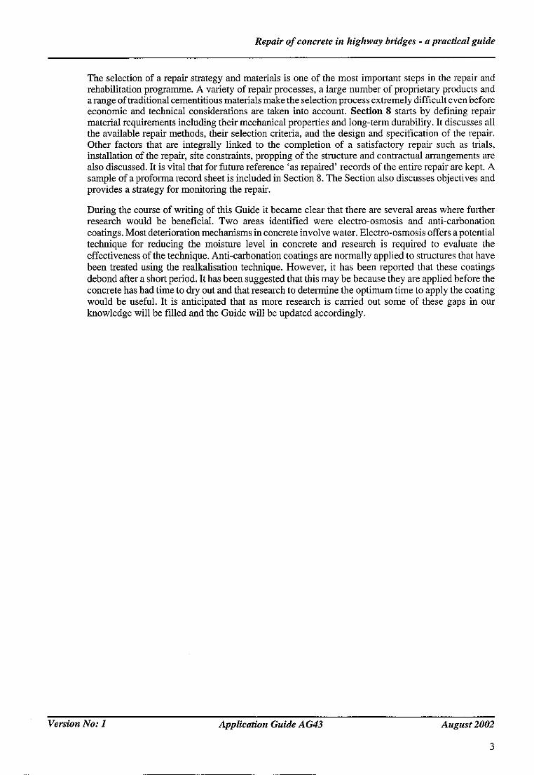
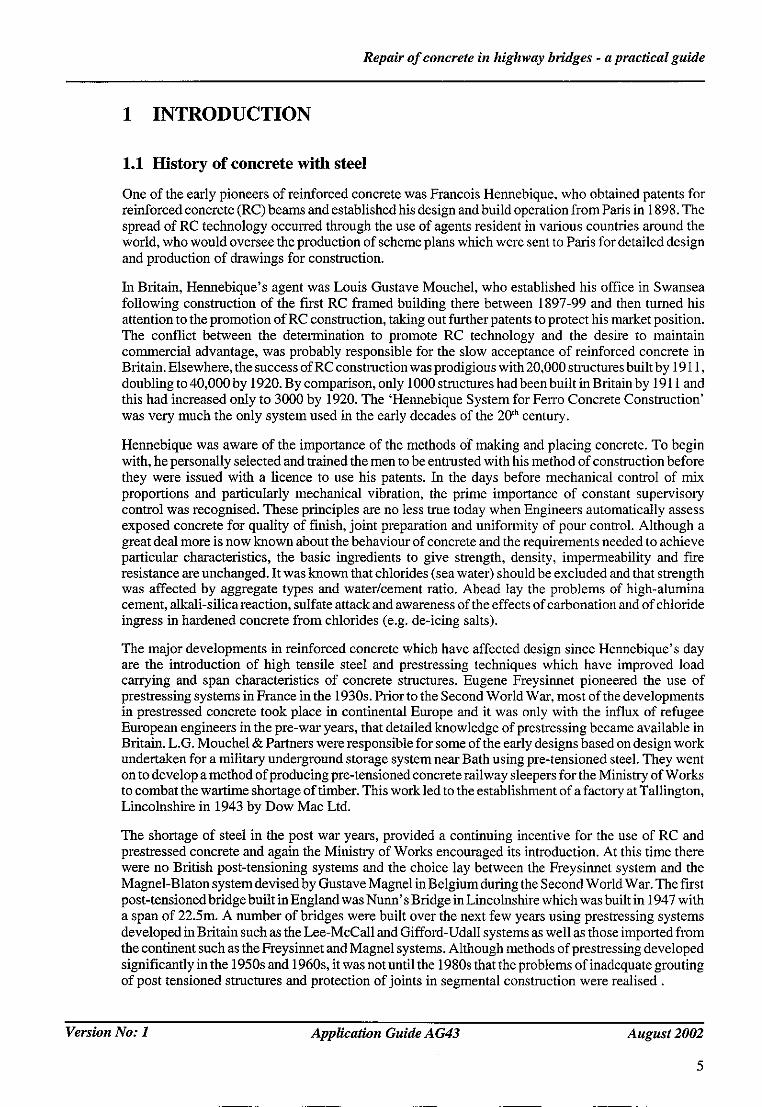
Once reinforcement corrosion has initiated it proceeds at a rate largely governed by the ambient temperature and the resistivity of the concrete which in turn depends on its moisture and chloride content. Usually significant amounts of damage can result within 20 years of corrosion starting. Corrosion caused by carbonation results in general corrosion (see Figure 2.1) and leads to cracking, spalling and delamination of the concrete before significant reductions occur in the cross sectional area of the reinforcement. This type of damage reduces the steel-concrete bond which can affect the flexural strength of the element and spalling concrete from overbridges is a hazard to traffic. Corrosion caused by chlorides can also result in cracking (see Figure 2.2), spalling and delamination but, in addition it can cause intense pitting corrosion of the steel, substantially reducing its cross sectional area (see Figure 2.3) and strength.
2.2 Alkali silica reaction
Alkali silica reaction (ASR) is a chemical reaction between aggregate particles and the alkali in cement. This reaction product is a silicate which swells when it absorbs water causing stresses which fracture the concrete. The reaction product is a white precipitate which is often, through not always, seen emanating from the cracks in the concrete. ASR normally occurs during the first 20 years of a structures life and requires three substances to be present simultaneously:
• reactive aggregate particles e.g. opal, flint;
• concrete with alkali content greater than 3kg/m3;
• concrete with a high moisture content.
The allowed and excluded combinations of aggregate reactivity and cement alkalinity for new construction are defined in BRE digest 330 and Concrete Society Report TR30. Most cases of ASR observed in the UK have involved exposure to an external source of water such as rain, condensation or ground water.
The cracks which result from ASR tend to form a map pattern in lightly or unreinforced concrete (see Figure 2.4). In heavily reinforced and prestressed elements the cracks are more likely to be coincident with the main reinforcement and prestressing steel, respectively. The cracking can be quite severe and certainty detracts from the appearance of a bridge, but in most cases the structural effects are limited (ISE 1988). The cracks caused by ASR can increase the risk of secondary reinforcement corrosion occurring at a later date. Modem bridges should not suffer from ASR since the alkali content of the cement and aggregate reactivity were controlled by standards issued in 1988 (BCA, 1992) and 1999 (BRE Digest 330) and now incorporated in the Specification for Highway Works.
2.3 Freeze-thaw attack
Freeze thaw attack sometimes occurs on concrete in colder regions of the UK. It starts at the concrete surface and moves inwards towards the body of the element. The surface concrete scales and crumbles away exposing a fresh surface. Freeze thaw damage is most likely when:
• the concrete undergoes a high frequency of freeze thaw cycles;
• the concrete quality is poor;
• the concrete is saturated with water, particularly saline water.
Version No: 1 Application Guide AG43 August 2002
10
Repair o f concrete in highway bridges - a practical guide
Figure 2.1 General corrosion of reinforcement caused by carbonation of concrete
Figure 2.2 Corrosion of reinforcement causing cracking and rust staining in a bridge element
Version No: 1 Application Guide A G43 August 2002
11

Repair o f concrete in highway bridges - a practical guide
Figure 2.3 Pitting corrosion of reinforcement caused by chloride penetration in concrete
Figure 2.4 Example of map cracking (on vertical face) due to ASR
Version No: 1
12
Application Guide A G43 August 2002

Repair of concrete in highway bridges - a practical guide
Deicing salts such as sodium chloride or calcium chloride can make concrete surfaces more susceptible to frost damage and scaling. This is thought to result from osmotic pressure causing movement of water towards the surface of the concrete where freezing takes places (Powers, 1956).
In most cases, freeze thaw damage does not have structural consequences although it has sometimes caused problems in certain elements (see Figure 2.5). It could also increase the risk of reinforcement corrosion if the damage is not repaired.
Figure 2.5 Example of surface scaling and structural damage caused by severe frost attack
2.4 Sulfate attack
Sulfate attack usually occurs on concrete buried in soil with a high sulfate or sulphide level (sulphide can be oxidised to sulfate). It can also occur in concrete above ground and in seawater where the sulfate content of the cement is abnormally high. Sulfate attack starts at the concrete surface and moves progressively inwards. The rate of attack is usually much higher than for frost attack and substantial damage can occur which could have structural consequences. Sulfate attack can be prevented by the use of special cements such as sulfate resisting Portland Cement.
The Guide does not specifically address concrete repairs to reinforced concrete below ground level. However, as with all repairs it is essential to determine the cause of any defects or deterioration in the concrete before deciding on the options for remedial work. It is also important to determine the effects and influence of the prevailing or anticipated ground conditions. Reference should be made to BRE Special Digest 1 entitled 'Sulfate and acid resistance of concrete in the ground' (BRE, 200I ) and to the Report of the Thaumasite Expert Group published in 1999 as 'The thaumasite form of sulfate attack: Risks, diagnosis, remedial works and guidance on new construction' (Thaumasite Expert Group, 1999).
The latter document in particular gives current best practice on remedial works including concrete repairs where thaumasite sulfate attack is encountered. An important issue is the prevention of recurrence of the concrete deterioration. Measures such as the use of protective membranes, improved drainage, replacement with non-aggressive backfill and the use of protective layers produced in low- carbonate concrete should be considered.
Version No: 1 Application Guide A G43 August 2002
13

Repair o f concrete in highway bridges - a practical guide
2.5 Plastic settlement and early thermal cracks
These cracks occur very early in the life of a structure (Concrete Society, 1992) but rarely cause any immediate problems. Plastic settlement cracks are formed due to restraint between the concrete and the reinforcement or the formwork. As the concrete, particularly with high bleeding water, settles under the process of settlement, it tears and cracks between the restraints. Early thermal cracking is a consequence of the heat of hydration of the mix with high cement content in a mass concrete. In thicker sections with a large volume, the concrete becomes insulating at outer edges as it hydrates. This results in substantial increase in temperature in the central core of the element. The temperature difference leads to early thermal cracking. More information on these subjects can be found in Table 3.1 and Figure 3. I. Normally, these types of cracking would have been sealed at the construction stage. These cracks, if not sealed, can increase the risk of corrosion occurring later.
2.6 Factors affecting concrete deterioration
The forms of deterioration described in sections 2.1 to 2.5 usually occur in conjunction with other factors that can be classified under the headings materials, design, construction and environment and which are listed in Table 2.1.
Table 2.1 Factors causing deterioration of concrete bridges
Materials Design Construction Environment
Low concrete strength Poor drainage details Poor compaction Chlorides High water/cement ratio Congested reinforcement Honeycombing Carbonation Highly alkaline cement Poor joint design Early age cracking Sulfates Reactive aggregates Poor mix design Low cover Water CaCI_, additive Non-inspectable areas
Deterioration caused by material, design and construction problems can only be reduced by improvements made before and during construction. Deterioration due to environmental factors should be allowed for in the design but can also be controlled to some extent during service by adopting a range of preventative maintenance approaches. The performance of these protective measures is, however, significantly reduced if the bridge has shortcomings in material, design and construction. In order to achieve satisfactory durability it is, therefore, essential to pay particular attention to factors such as:
• cover depth;
• water/cement ratio;
• concrete mix design;
• choice of formwork;
• drainage details;
• joint design;
• detailing;
• workmanship;
• compaction;
Version No: 1
14
Application Guide A G43 August 2002
Repair o f concrete in highway bridges - a practical guide
• water management;
• inspectability;
• maintainability;
in addition to providing protection against aggressive substances in the environment. Both approaches to improving durability are necessary, but neither is sufficient by itself.
Most deterioration processes involve water in some way and much could be achieved by improving the detailing of kerbs, joints, parapets, upstands, drainage systems and waterproofing membranes and avoiding the formation of sinks where water can accumulate and persist for considerable periods of time (Pearson and Cuninghame, 1998). Regular routine maintenance such as cleaning drains and vegetation control and removal may avoid more serious maintenance at a later date.
Some forms of deterioration and defects, although often not producing serious consequences immediately, can result in corrosion occurring sooner because the transport, through the concrete, of aggressive substances in the environment is facilitated. Examples are freeze thaw damage, ASR cracking, other forms of cracking, impact damage and honeycombed concrete. The risk of secondary corrosion can be reduced by crack injection with resins or the use of crack bridging coatings.
The main additional protective measures against aggressive substances in the environment are:
• silane impregnation to protect against chlorides and to some extent against water;
• anti-carbonation coatings to protect against carbonation;
• waterproofing membranes to protect against water, chlorides and sulfates;
• cast in corrosion inhibitors;
• joint replacement to protect against water and chlorides.
Although many of the material, design, construction and environment defects are often present the occurrence of most of the main forms of deterioration (ASR, freeze thaw damage and sulfate attack) is thankfully comparatively rare. For example the percentage of the bridge stock suffering from these forms of deterioration at some time during their life is likely to be much less than one percent. This is because:
• for ASR three conditions (given in section 2.2) must be satisfied simultaneously;
• for freeze thaw damage the number of freeze thaw cycles per year is relatively few for most places in the UK;
• for sulfate attack the presence of high levels of sulfates in soils is not common and should be detected by pre-construction tests allowing sulfate resisting cement to be used to prevent the problem from occurring.
Corrosion of reinforcing steel is, however, likely to affect some parts of nearly all bridges in the UK at some time during their lives because a high proportion of the road network is deiced with rock salt (sodium chloride) during the winter and protective treatments against chloride ions are only partially effective. Corrosion of reinforcing steel is, therefore, the most common type of deterioration by far and to reflect this fact the remainder of this guide to concrete repair relates predominantly to deterioration related to the corrosion process.
Deterioration caused by ASR, freeze-thaw and sulfate attack are not covered in this Guide and references should be made to specialist reports such as those given in the list of references.
Version No: 1 Application Guide A G43 August 2002
15

Repair o f concrete in highway bridges - a practical guide
3 INSPECTION
The inspection of bridges is the primary method for monitoring the condition of the stock, detecting defects and providing assurance that bridges are safe and serviceable.
There are two types of inspection that are carried out routinely at specified intervals. General inspections are typically carried out every two years and Principal inspections are carried out every six years.
General inspections only involve visual observations which are made from convenient access points without the use of special equipment e.g. hoists. Binoculars and torches can be used to aid observations of distant and dark parts of the bridge. In many situations it will not be possible to inspect all parts of a bridge during a general inspection.
Principal inspections are mainly based on visual observations although these are usually supplemented by sampling and non-destructive testing especially at the first principal inspection. Visual observations must be made at a distance of less than one metre from all parts of the bridge and this often involves the use of access hoists and platforms and lighting.
The supplementary techniques used during principal inspections include cover depth, half cell potential and sampling to determine chloride content and carbonation depth of the concrete. Only a small number of these tests are carried out in areas that are considered to be most vulnerable to reinforcement corrosion.
The procedures for bridge inspection will change during the next few years as the new Bridge Inspection Manual, issued by the Highways Agency, is fully implemented and will potentially influence the inspection of local authority bridges. The main difference with existing procedures is that the timing and constitution of the different types of inspection are less rigidly prescribed so the interval between inspections, for example, may be varied according to various guidelines. The details of the different test methods used in inspections remain little changed, however. A useful feature of the new manual is that it provides a much more detailed explanation and description of the defects that can occur and the tests that can be used on concrete bridges.
Many of the observations made during bridge inspections relate to deterioration of the concrete surface even though the cause of the problem may also involve the reinforcement. Indications of deterioration typically observed during inspections are:
• water leaks from construction or expansions joints or defective drains:
Water leaks onto concrete are a problem because (a) the concrete becomes saturated making it more susceptible to freeze-thaw damage and (b) if the water contains de-icing salt, chloride ions can enter the concrete and cause the steel reinforcement to corrode. These problems are exacerbated if the concrete is already cracked or spalled.
• lime leaching:
Lime leaching indicates that the alkalinity in the concrete that passivates the reinforcing steel is being progressively lost.
• rust staining:
Rust staining is a clear indication that the steel reinforcement is corroding although the position of the staining is not always a reliable guide to the location of the corroding reinforcement. Rust staining can also result from corroding steelwork (beams, bearings, drain pipes) and rusting tie wire. Staining from pyrite aggregate particles can be mistaken for rest staining.
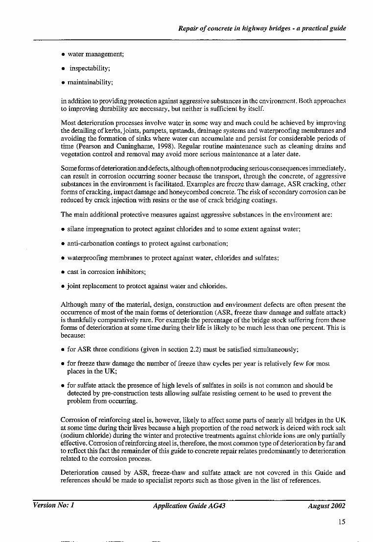
• scaling:
Scaling of concrete (see Figure 3.1) often results from freeze-thaw attack, but the extent of penetration into the concrete is usually limited and rarely reaches the reinforcement. De-icing salt will penetrate more easily into scaled concrete.
Version No: 1 Application Guide A G43 August 2002
17
Repair o f concrete in highway bridges - a practical guide
Figure 3.1 Scaling of surface of concrete wing wall
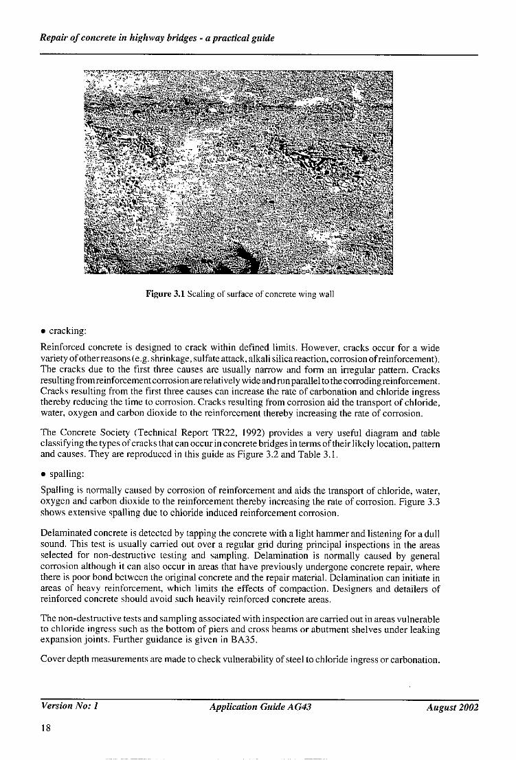
• cracking:
Reinforced concrete is designed to crack within defined limits. However, cracks occur for a wide variety of other reasons le.g. shrinkage, sulfate attack, alkali silica reaction, corrosion of reinforcement). The cracks due to the first three causes are usually narrow and form an irregular pattern. Cracks resulting from reinforcement corrosion are relatively wide and run parallel to the corroding reinforcement. Cracks resulting from the first three causes can increase the rate of carbonation and chloride ingress thereby reducing the time to corrosion. Cracks resulting from corrosion aid the transport of chloride, water, oxygen and carbon dioxide to the reinforcement thereby increasing the rate of corrosion.
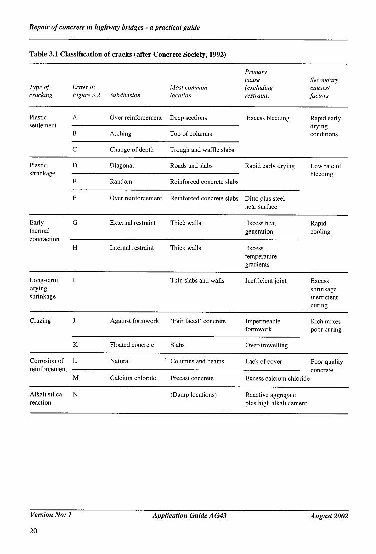
The Concrete Society (Technical Report TR22, 1992) provides a very useful diagram and table classifying the types of cracks that can occur in concrete bridges in terms of their likely location, pattern and causes. They are reproduced in this guide as Figure 3.2 and Table 3.I.
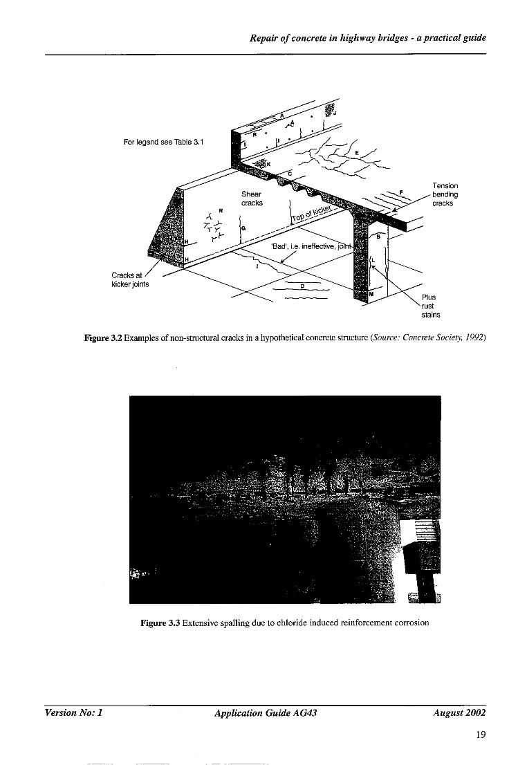
• spalling:
Spalling is normally caused by corrosion of reinforcement and aids the transport of chloride, water, oxygen and carbon dioxide to the reinforcement thereby increasing the rate of corrosion. Figure 3.3 shows extensive spalling due to chloride induced reinforcement corrosion.
Delaminated concrete is detected by tapping the concrete with a light hammer and listening for a dull sound. This test is usually carried out over a regular grid during principal inspections in the areas selected for non-destructive testing and sampling. Delamination is normally caused by general corrosion although it can also occur in areas that have previously undergone concrete repair, where there is poor bond between the original concrete and the repair material. Delamination can initiate in areas of heavy reinforcement, which limits the effects of compaction. Designers and detailers of reinforced concrete should avoid such heavily reinforced concrete areas.
The non-destructive tests and sampling associated with inspection are carried out in areas vulnerable to chloride ingress such as the bottom of piers and cross beams or abutment shelves under leaking expansion joints. Further guidance is given in BA35.
Cover depth measurements are made to check vulnerability of steel to chloride ingress or carbonation.
Version No: 1
18
Application Guide A G43 August 2002
Repair o f concrete in highway bridges - a practical guide
For le!
Cracks at kicker join
t u ~ L
stains
Figure 3.2 Examples of non-structural cracks in a hypothetical concrete structure (Source: Concrete Socie~, 1992)
Figure 3.3 Extensive spalling due to chloride induced reinforcement corrosion
Version No: 1 Application Guide A G43 August 2002
19
Repair o f concrete in highway bridges - a practical guide
Table 3.1 Classification of cracks (after Concrete Society, 1992)
Primary cause Secondary
Type of Letter in Most common (excluding causes/ cracking Figure 3.2 Subdiviston location restraint) factors
Plastic A Over reinforcement Deep sections Excess bleeding Rapid early settlement drying
B Arching conditions
C
Top of columns
Change of depth Trough and waffle slabs
Plastic D Diagonal shrinkage
E Random
F
Roads and slabs Rapid early drying Low rate of bleeding
Reinforced concrete slabs
Over reinforcement Reinforced concrete slabs Ditto plus steel near surface
Early G External restraint Thick walls Excess heat Rapid thermal generation cooling contraction
H Internal restraint Thick walls Excess temperature gradients
Long-term I Thin slabs and walls Inefficient joint Excess drying shrinkage shrinkage inefficient
curing
Crazing J Against formwork 'Fair faced' concrete Impermeable Rich mixes formwork poor curing
K Floated concrete Slabs Over-trowelling
Corrosion of L Natural Columns and beams Lack of cover Poor quality reinlbrcement concrete
M Calcium chloride Precast concrete Excess calcium chloride
Alkali silica N (Damp locations) Reactive aggregate reaction plus high alkali cement
Version No: 1
20
Application Guide A G43 August 2002
Repair o f concrete in highway bridges - a practical guide
Carbonation depth measurement is made using the pH indicator, phenolphthalein. A colourIess reaction indicates the depth of the carbonated zone. This test must be carried out on a freshly exposed concrete surface that is normally most neatly obtained by splitting a small diameter core axially. The combination of bridge age, cover depth and depth of carbonation can be used to provide a rough estimate of the rate of carbonation and time to corrosion.
Samples of concrete for chloride analysis can be extracted by percussion drilling or coring. If coring is selected the same core that was used for the carbonation test can be used for chloride analysis. It is important that the core is sliced perpendicular to the axis to provide at least three samples from different depths. The deepest depth should correspond to the cover depth in that area. The results can then be used to give a rough estimate of the chloride flux and time to initiate corrosion.
Half-cell potential measurements are carried out on grids in the vulnerable areas; the maximum grid dimension is 0.5m. The test should indicate whether the reinforcing steel has started to corrode and may indicate if the corrosion is general or localised. Great care is required when interpreting the results. Decisions on reinforcement condition should not be made on half-cell potential measurements alone.
There are two useful guides which explain both the theory and practice of half cell potential measurements:
• TRL Application Guide No 9, 1990.
• Concrete Society/ICORR, Current Practice Guide, 2000.
Version No: 1 Application Guide AG43 August 2002
21

Repair o f concrete in highway bridges - a practical guide
4 INVESTIGATION
4.1 Overview of investigation
Defects and deterioration generally come to light during general or principal inspections and may trigger a special inspection and some investigative work. A primary objective of the investigation is to determine causes of deterioration. However, this should be followed by an assessment of the extent of the deterioration, the rate of deterioration and the ability of the structure to perform its intended function. The process of assessment should include but not be limited to the following:
• the present condition of the structure including visible arid non-visible defects and the future potential deterioration;
• the original design approach, which may identify inadequacies in design, specification, execuuon and/or materials;
• the history of the structure including as built, inspection and maintenance records;
• the environment including exposure conditions and contaminants;
• the conditions of use (e.g. loading);
• the requirements for the future use of the structure.
The results of the completed assessment will be valid at the time when it is carried out. If there is a considerable passage of time between the assessment and the implementation of the repair or there are doubts about the validity of the assessment, a new assessment should be made. In some circumstances, it may be possible to estimate when an element or whole of the structure would reach the end of the design life if no repair is carried out. The following sections describe structural and management issues, and their respective assessment. Non-destructive and semi-destructive testing of the reinforced concrete is also summarised.
The purpose of testing is to establish (a) the cause of deterioration, (b) the rate of deterioration, (c) the extent of deterioration, (d) severity and (e) the effect of deterioration on the load carrying capacity of the bridge and the safety of the public.
The information arising from a special inspection should be sufficient to enable decisions to be made about:
• whether essential maintenance is necessary;
• which remedial procedures would be effective for repairing damage and preventing further deterioration;
• the extent of repairs necessary;
• the most appropriate time to carry out repairs.
Essential maintenance is work that must be carded out immediately in order to safeguard the public and to reduce the risk of structural collapse to an acceptable value. If essential maintenance is not carded out immediately other measures such as traffic restrictions must be imposed to reduce loads enough to reduce the risk of collapse to an acceptable value. Reference should be made to BA79.
Deterioration that causes the concrete to be damaged usually requires a remedial procedure that has two functions namely (a) to repair the damaged concrete and (b) to terminate the deterioration process causing the damage and to prevent its re-occurrence in the future. Sometimes concrete repairs can
Version No: 1 Application Guide AG43 August 2002
23

Repair o f concrete in highway bridges - a practical guide
satisfy both functions but it is becoming more common to use a different procedure for each function. Once deterioration has progressed to the stage that concrete damage results then preventative maintenance is unlikely to be effective.
The choice of maintenance type (preventative, repair, strengthening) depends on the condition of the bridge element under consideration. The choice of a particular maintenance method depends on the cause and extent of deterioration.
A knowledge of the extent of deterioration enables the cost of the work to be estimated. It also provides guidance on how the work should be programmed and whether traffic management will be needed and for how long. This enables the level of traffic disruption associated with the repair work to be assessed.
Unless the maintenance is essential the criterion for deciding whether or not maintenance is justified should be based on the whole life costing. The whole life cost depends on the cost of maintenance currently being considered, the period of maintenance free life that results and the cost of subsequent maintenance work.
4.2 Non-destructive testing
A wide range of tests can be applied during a special inspection. The purpose of the more commonly used tests are described below. Further details can be obtained from the authoritative Technical Guide No 2 entitled 'Guide to Testing and Monitoring the Durability of Concrete Structures' issued by the Concrete Bridge Development Group (2002).
Cover depth, chloride content, carbonation depth and half-cell potential tests have been considered previously in the section on bridge inspection. In special inspections these tests are carried out over more extensive areas, often a complete element, in order to estimate the extent of corrosion reinforcement and the duration and cause of corrosion. It may also be possible to decide if the corrosion is general or localised by considering the potential gradient from an equipotential contour plot of the half-cell potential measurements. These tests are normally carried out on a regular grid of dimension 0.5m for half-cell potential and cover depth and about 2m for chloride and carbonation. The analysis of concrete samples for chloride, taken from different depths in areas where corrosion has not yet started, provides a prognosis for how the extent of repairs will increase with time. Carbonation depth measurements can be used in a similar way. This information is useful when calculating whole life costs.
Visual observations and a delamination sounding survey are carried out over all the exposed surfaces of the element under consideration using the grid set up for the tests described in the last paragraph. These tests provide the area of concrete damage which can be regarded as the minimum area for concrete repairs.
Grid lines can be drawn on the element surface with the aid of a chalk line. These chalk lines are visible for no more than a few weeks so the appearance of the bridge is only temporarily affected.
Visual observations should also be used to locate areas subject to ponding and leaking water; these areas are particularly vulnerable to deterioration. The source of leaks e.g. joints, drainage, waterproofing should be established because the rectification of leaks forms an essential part of any remedial work.
Measurements of the electrical resistivity of concrete can be used in a number of ways:
• where other measurements indicate that corrosion has not yet started, resistivity measurements can provide an indication of the rate of corrosion that may be experienced if and when it initiates. Very high resistivities (> 100 Kohm.cm) on outdoor concrete in the UK indicate a very dense concrete through which the passage of depassivators is likely to be low. Conversely very low resistivities (< 10 Kohm.cm) indicate the presence of damp concrete with a relatively high porosity. In circumstances where the moisture contains chloride ions corrosion initiation could be imminent and will occur at a significant rate;
Version No: 1 Application Guide AG43 August 2002
24

Repair o f concrete in highway bridges - a practical guide
• where other measurements indicate that corrosion has started, a low resisitivity (<10 Kohm.cm) indicates that the rate of corrosion is likely to be high; low resistivities in the presence of chloride ions are the conditions needed for localised corrosion which leads to pitting of the steel and significant reductions in reinforcement cross section. Conversely high resistivities indicate a low rate of general corrosion.
The corrosion rate of reinforcing steel depends on the electrical current flowing through the concrete between anodes and cathodes on the reinforcement. This current depends on the difference in potential between the anode and cathode (typically about 0.4V) and the resistivity of the concrete. A high resistivity substantially limits the current that can flow and hence the rate of corrosion. Corrosion currents can be measured directly using a technique called linear polarisation resistance either in specific locations or over a grid. Only an approximate value of corrosion rate can be inferred because corrosion currents vary significantly from day to day due to variations in temperature and moisture content of the concrete. Furthermore, corrosion currents in one location will be influenced by changes in the electrochemical characteristics of adjacent corrosion cells. It is therefore beneficial to make gridded measurements of corrosion current over a significant area of concrete surface. Corrosion current measurements do not appear to be particularly reliable for measuring the rate of pitting corrosion. Experience indicates that pits grow at a rate of 0.5 to 3mm per year and the use of these values may be a more useful way of deducing the prognosis of pitting corrosion.
4.3 Semi-destructive tests
Concrete cores are taken for a variety of purposes:
• to measure the strength of the concrete ( the strength of reinforcement is usually obtained from separate samples, a minimum of 300mm long which involves concrete break-out);
• for chloride and carbonation tests as described previously;
• to assess the compaction of the concrete and the presence of honeycombing;
• to assess the homogeneity of the concrete;
• to examine for evidence of alkali silica reaction, sulfate attack or frost damage;
• to assess the modulus of elasticity of the concrete to assist with a selection of the repair material.
Some cores are usually taken through sound concrete while others are taken in deteriorated concrete in order to elucidate the cause of deterioration.
Tests to check the effectiveness of waterproofing membranes and silane treatments in preventing chloride ingress should also be considered when carrying out a special inspection. The top surface of a bridge deck is covered with a waterproofing membrane and asphalt surfacing hence any defects or deterioration is likely to remain hidden until it reaches a very advanced stage. In this situation sample cores through the surfacing and into the concrete can be taken to look for indications of deterioration/chloride ingress which, if found, may necessitate localised removal of the surfacing and waterproof membrane to allow closer examination of the concrete surface in affected areas. Delamination of the membrane from the concrete may also indicate potential problems, ff protective systems are at or near the end of their life its replacement as a part of the remedial works is likely to be justified to limit the amount of traffic dismption associated with maintenance during the life of a bridge.
Localised corrosion can sometimes develop to a substantial level before any visual indications are evident. This can affect the safety of the structure necessitating bridge strengthening where earlier detection would have resulted in a requirement for much tess extensive maintenance. At present, there are no effective non destructive techniques for determining the loss of reinforcement cross section in situ. Non destructive techniques are available for determining the rate of corrosion but it is difficult to
Version No: 1 Application Guide AG43 August 2002
25

Repair of concrete in highway bridges - a practical guide
use this information to find the cumulative loss of section because:
• corrosion rate measurements are instantaneous and not cumulative;
• corrosion rate can vary substantially from hour to hour due to changes in environmental conditions.
It is therefore necessary to expose the reinforcement for examination in some trial areas where localised corrosion is thought to be occurring. The possibility of localised corrosion is indicated by the results of the half cell potential and resistivity non-destructive tests. The criteria for localised corrosion are:
• resistivities less then 15 Kohm.cm;
• high potential gradient (> 0.3 V m-L);
• low half cell potentials (< - 400mV vs saturated Cu/CuSO4).
In order to estimate the potential gradient the half cell potentials must be plotted as equipotential contour lines. It should be emphasised that the above criteria only provide a guide to the circumstances under which localised corrosion can occur. Localised corrosion can occur when these criteria are not satisfied and visa versa.
The trial exposure area should have a minimum area of about 0.5m 2. The concrete should be removed to a depth of about 15 mm beneath the reinforcement. Ideally, the concrete should be removed by water jetting since this does not damage the reinforcement or the remaining concrete. If percussion drills are used to remove the concrete particular care should he taken not to hit the reinforcement since this can cause as much damage as the localised corrosion. As soon as the concrete has been removed the reinforcement should be examined for signs of corrosion and in particular the colour of the corrosion deposit. If it is black, green or white this is an indication of localised corrosion. If it is brown then the corrosion is probably not localised. It is important to carry out this examination as soon as the concrete is removed since the black, green and white corrosion deposits are rapidly oxidised on exposure to air and are converted to the brown form. It is also important to note whether the corrosion deposit covers most of the exposed bars or is confined to small areas with the remainder of the bars being tEn-COrroded since the latter provides a positive indication oftocalised corrosion. Any corrosion deposit should be removed by water jetting or mechanical wire brash. This will reveal the profile of the bar. Any clearly defined regions of corrosion can be assessed by measuring the minimum bar diameter using callipers or micrometer. These instruments need to be of a design capable of access beneath the reinforcement. The profile nfthe bar can be drawn with the aid of a profilometer. Small diameter pits can be examined using a micrometer with special attachments for measuring the pit depth. This can be difficult because the pit is often packed with corrosion product that can be difficult to remove even by water jetting.
Note that if the concrete is cut away by water jetting it is easy to unintentionally remove the corrosion deposit at the same time so that its characteristics cannot be examined.
4.4 Structural assessment
Before carrying out any work on a bridge, other than minor cosmetic repairs, it is essential to carry out a structural strength assessment. This is part of the overall investigation and information gathering process required to determine the extent of work. Calculations may also be necessary to determine the amount of concrete that can safely be removed during a repair operation without restricting live load or providing temporary supports where the highway must remain open. The effect of concrete repairs on the future performance of the bridge also needs to be taken into account. This section is not a comprehensive review of the topic and further advice should be sought from the literature.
A principal source of reference is the Highways Agency BA 51, 'The Assessment of Concrete Structures affected by Steel Corrosion'. The key points from this document are summarised below. BD44 and BA44
Version No: 1 Application Guide AG43 August 2002
26

Repair o f concrete in highway bridges - a practical guide
provide further advice on the assessment of deteriorated structures. Although it may be desirable to deal, as soon as possible, with corroding structures, there may be insufficient resources to allow this to happen. It is very important, therefore, to consider the assessment of the bridge stock as a continuous process rather than a single 'snap shot' in time. In this way the risk associated with the strength and safety of the structure can be monitored and intervention arranged before the structure reaches a critical state.
There are two types of corrosion - local and general. Local corrosion leads to section loss although the relationship is not directly proportional. Advice on the determination of the effective cross-sectional areas of bars is contained in BA38. This Advice Note should also be used to check the fatigue strength of corroded bars subjected to significant live load stress range. The main structural effect of general corrosion is loss of bond, although it may be necessary to check for overall loss section.
In order to maintain the safety of the structure, it will be necessary to consider the rate of deterioration and introduce a monitoring procedure so that this can be reviewed at future Special Inspections.
Local corrosion creates stress concentration in reinforcement yields. Bars which are considered to be suffering from local corrosion should not be considered to be effective in plastic analysis, such as yield line analysis.
Tests have shown that the loss of bond strength caused by general corrosion, is not significant until the point when longitudinal cracks form over the bars. Then the bond strength should be reduced by 30%. Where the concrete cover is less than one bar diameter and there are no links, includes a reduction factor for bond stress which is over and above the reductions required by BD44.
More recent work has been published (Mangat and Elgarf, 1999a) which shows that bond strength can vary widely depending on the degree or corrosion. They have also shown (Mangat and Elgarf, 1999b) that marked reductions in flexural strength can occur due to reinforcement corrosion and this is caused primarily by the breakdown of bond at the steel/concrete interface. These results conflict with other published material (Cairns, 1993) which suggests that reinforced concrete beams may be capable of carrying a significant proportion their load capacity even where reinforcement is exposed over a major proportion of the span. Clearly this aspect needs to be treated with caution and further clarification and guidance is required.
Where the cover concrete is spalling or delaminating over a significant area, the structure should be assessed ignoring the cover concrete in those regions. The bond of bars in areas of delamination should also be ignored. The bars should also be ignored for the purposes of calculating the concrete shear strength unless they are restrained by links which are still effective.
The behaviour of reinforced concrete slabs is such that they are less susceptible to the effects of local corrosion than beams.
Some of the effects of corrosion on the assessment of concrete bridges have been considered. It has, perhaps, previously been considered that once a repair has been carded out by replacing or cleaning corroded steel and patching the concrete, that the strength of the stmcture has been fully restored. However, this may not necessarily be the case.
The Key points from research are:
• Corrosion significantly affects the assessment results.
• The loss of bond strength may be more significant than current HA advice suggests.
• The type of repair material can have a significant effect on the future strength of the bridge.
• The method of working during repair can have a significant effect on the future strength of the bridge.
• The assessing engineer needs to take particular care where concrete repairs have been carried out and note should be taken of as-built records.
Version No: 1 Application Guide AG43 August 2002
27
Repair o f concrete in highway bridges - a practical guide
5 REVIEW AND ASSESSMENT
5.1 Introduction
The outputs from Sections 3 and 4 on inspections and investigation should provide sufficient information on:
• the causes and nature of the problem;
• the current condition of each bridge element;
• the extent of the problem on each element;
• the estimated rate of future deterioration;
• the load carrying capacity of the deteriorated bridge;
• site specific factors which could influence the maintenance strategy;
• to enable the situation to be assessed and decisions to be taken on;
• the most appropriate maintenance strategy;
• the best time to carry out repairs/maintenance;
• the extent of maintenance work required.
The causes of reinforcement corrosion fall into two categories, physical and/or chemical. Physical causes are typically leaking expansion or construction joints which cause significant areas of concrete to come into contact with saline water. Another physical cause is poorly compacted or honeycombed concrete which can result in accelerated carbonation and other deterioration process. Chemical causes related to the substance in the bridge environment that is depassivating the reinforcing steel i.e. chloride ions or carbon dioxide. It is important to identify the chemical cause since this plays an important part in deciding the best methods for preventing or stopping reinforcement corrosion. Physical causes must be identified and rectified to minimise the risk of the problem re-occmring in the future. The nature of corrosion i.e. localised or general form indicates the type of damage that occurs. The current condition of an element will help in deciding the most appropriate maintenance strategy. For example if an element has suffered significant chloride contamination, but the reinforcing steel has not yet started to corrode a preventative maintenance strategy is indicated. If, on the other hand, corrosion has already started the appropriate strategy would be to reduce the corrosion process and repair any damaged concrete. For bridges where more than one element is showing signs of deterioration it is reasonable to consider bringing forward maintenance work on the less deteriorated elements so that all the known problems can be tackled at the same time thereby avoiding additional access, traffic management and disruption costs that would result from an early return to the bridge for additional maintenance. A good target is that on completion of maintenance work a bridge should be largely free of maintenance for the next 20 years.
The extent of deterioration on an element has a significant influence on the choice of maintenance strategy and method. For example ffthere is extensive concrete damage to an element patch repairs may not be viable and it may be necessary to replace the element or strip all the cover zone concrete, shutter and repair with a flowable concrete, whilst providing temporary support.
It is useful to have an estimate of the rate of deterioration of an element since this can help to prioritise maintenance work on different bridges and particularly where the funding available is insufficient to carry out all the identified maintenance in a given year. In principle a knowledge of the rate of deterioration should enable the age at which deterioration results in a bridge becoming substandard to be estimated. In practice, at the present time, such estimates are very approximate due to limitations
Version No: 1 Application Guide A G43 August 2002
29

Repair o f concrete in highway bridges - a practical guide
of the methods used to measure the rate of deterioration. Ideally the method should measure the amount of reinforcing steel remaining in a corroded element at a given time, however, at present the only available techniques measure the rate of corrosion which is an instantaneous measure. In other words a single measurement of corrosion rate only indicates the rate at the time of the measurement and this may be very different from the average value of rate taken over a year say, because the rate of corrosion is known to vary significantly over a day or week due to changes in temperature and concrete conductivity. Variations in rate over somewhat longer periods can result from changes in concrete corrosivity. A single measurement of rate provides no reliable information about historical values of corrosion rate or when corrosion started. In the same way a single measurement is not a reliable measure of the corrosion rate in the future. A single measurement is, therefore, inadequate for estimating the amount of steel remaining.
This problem could only be overcome if corrosion rate monitoring took place throughout the life of the element and this has not been the normal practice. The current rate of corrosion is however a reasonable guide to what may happen in the next decade. Corrosion rates vary significantly with the ambient temperature and moisture content of the concrete, which can change significantly from hour to hour due to changes in the weather. To obtain a reasonable estimate of the rate of corrosion for future predictions of condition it is, therefore, necessary to monitor the corrosion rate at hourly intervals over a 9 month period in order to take account of short term and seasonal variations. However, it is not a practical or cost effective option but with development of new monitoring techniques this will become increasingly the norm in the future.
There are three main types of maintenance: essential, preventive and repair.
Essential maintenance is required when it becomes unsafe to use a bridge. This may occur for several reasons but the most common are as follows:
• When the load carrying capacity of a bridge is insufficient to carry the loads to which it is subjected. This is usually caused when the permissible load is increased by statute, but can also be caused by deterioration or by a combination of these two causes. In this situation the bridge is said to be substandard.
• When the soffit or piers of an overbridge suffer from reinforcement corrosion that can cause lumps of delaminated concrete to fall unpredictably into the road presenting a hazard to traffic passing under the bridge.
In either of these situations maintenance must be carded out immediately otherwise traffic restrictions must be imposed to make the bridge safe for use, hence the use of the term essential maintenance. The essential maintenance operations usually required are:
• to strengthen the bridge so that it can safely carry the required loads;
• to remove delaminated concrete and carry out concrete repairs.
The types of traffic restriction adopted before repairs are carded out are typically:
• to close lanes on the road underneath the bridge that are in danger of falling concrete;
• to close lanes over the substandard elements;
• to impose a weight restriction on the traffic using the bridge.
The purpose of preventative maintenance is to slow down the deterioration processes thereby increasing the serviceable life of the bridge. Preventative maintenance should increase the age of the bridge when essential maintenance is ultimately needed and may avoid its need altogether. The most commonly used types of preventative maintenance are the impregnation of concrete with silane, a
Version No: 1 Application Guide AG43 August 2002
30

Repair o f concrete in highway bridges - a practical guide
hydrophobic substance, covering concrete surfaces with waterproofing membranes and the painting of structural steelwork. All of these preventative treatments are designed to prevent corrosion of steel and are only likely to be effective when applied before corrosion initiates or after repair work that stops the corrosion process. Preventative maintenance is applied to all bridges that are not yet corroding. The justification for adopting a preventative maintenance strategy is that the lifetime cost for the bridge is reduced. Preventative maintenance is normally most effective when applied immediately after construction.
The purpose of repair work is to stop corrosion, prevent its reoccurrence and make good any damage to the concrete. Repairs should reduce the rate of deterioration thereby increasing the serviceable life of the bridge and the age at which essential maintenance becomes necessary. The most commonly used types of repair process are concrete repair and cathodic protection. Repair work is generally carried out following corrosion initiation. The justification for repair work is a reduction in whole life cost.
Knowledge of the load carrying capacity of a bridge will decide whether or not it is substandard which has a major bearing on the choice of maintenance strategy. If a bridge is shown to be substandard by the results of a load assessment the only possible maintenance strategies are:
• to strengthen or replace the affected elements;
• to apply traffic restrictions to reduce the Ioad;
• to regularly monitor the bridge for incipient indications of failure.
The last strategy is only valid when it can be demonstrated that any potential failure would be non- catastrophic in nature. In this respect, reference should be made to BA79.
If a bridge has adequate load carrying capacity then the maintenance strategy would be either:
• preventative maintenance;
• repairs;
• replacement;
• do nothing;
depending on which strategy generates the lowest whole life cost. The Highways Agency is currently trialling a system called Bid Assessment and Prioritisation System (BAPS), a computer based system that will replace BE14 and BE15. It stems from the Highways Agency's overall review of the management of trunk roads. BAPS combines the strategic needs of the network with the maintenance needs of individual structures. It takes account of alternative maintenance strategies, the application of whole life cost principles and the assessment of risk in terms of road user delays that result if work is not carried out. BAPS forms one module of a comprehensive bridge management system called Structures Management Information System (SMIS) which has been developed recently by the Highways Agency. It brings together information from a number of management tools to provide rational and consistent methods for the prioritisation of works and the determination of future maintenance needs.
A shortcoming of current assessment procedures is that the outcome is in the form of a pass-fail criterion. For bridges that pass the criterion it would be useful to know how easily they passed since this would help to prioritise and plan maintenance of the bridge stock.
Version No: 1 Application Guide AG43 August 2002
31

Repair o f concrete in highway bridges - a practical guide
5.2 Remedial techniques for structures vulnerable to reinforcement corrosion
There are a number of types of remedial measures:
(a) do nothing;
(b) preventative methods;
(c) methods for reducing the corrosion process;
(d) methods for repairing damaged concrete;
(e) maintaining the safety of structure users;
(f) methods for strengthening/replacement.
The condition of the structure determines which types are appropriate. This is important because the wrong choice of remedial measure is likely to be completely ineffective. Types (b) and (c) are only likely to be effective when applied before corrosion has initiated. Type (f) would only be relevant if the load carrying capacity of the structure has been shown to be inadequate and would be combined with methods (b) to (e) to stop further corrosion and prevent it from reoccurring. Types (c) and (d) are normally used together since it is unusual to find corrosion without any concrete damage. The use of type (e) on its own would normally only be considered if the strength of the deteriorated part of the structure was insensitive to the steel-concrete bond and to the steel cross section.
The amount of testing work on the structure that is needed in order to be able to specify a durable repair depends on the type of remedial measure. Testing prior to repair work is often important. It' s purpose is to ensure the correct repair/maintenance method and extent of repairs is used in order to achieve an effective and durable repair. For example preventative methods are often applied to the entire surface of a structural element so testing is only needed in order to decide the potential cause of deterioration. Sometimes, however, preventative measures are only applied to areas of the structure which have the most extreme exposure to corrosive substances in the environment or which are vulnerable to corrosion due to low concrete cover or because they are a sink where corrosive substances can accumulate. In this case testing and observations are also needed to locate the vulnerable areas.
Areas of damaged concrete can be determined by visual observation or by tapping the concrete surface with a hammer and listening for a low frequency audio response. Most techniques for stopping corrosion are often applied to the entire structural element hence pre-testing is only required to determine the cause of corrosion. Concrete repairs are an exception in this respect because if they are to stop corrosion for a substantial period of time tests are needed firstly to decide whether or not there is macroceU corrosion. If there is no macrocell corrosion concrete repairs should be effective if the damaged concrete is replaced and preventative measures are used to avoid further deterioration. If there is evidence of macrocell corrosion then extensive testing prior to repairs is needed in order to determine the total extent of all the anode-cathode cells since this is the area of the structure where concrete repairs are needed. The repair of this area should remove most of the chloride ions generally responsible for macrocell corrosion and prevent the formation of incipient anodes, although the extent of repairs may be too high to be viable.
In order to determine the degree of strengthening required, testing is needed to find the strength of the concrete and steel and the cross section of steel and steel-concrete bond still available after corrosion.
(a) Do nothing
In some instances remedial measures to deal with reinforcement corrosion may not be needed or may be deferred. For example, concrete more than about 8 meters from the road surface receive little exposure to deicing salts and is, therefore, not vulnerable to reinforcement corrosion unless the cover depth or concrete quality are abnormally poor. In these circumstances the 'do nothing' option is
Version No: 1
32
Application Guide AG43 August 2002
Repair o f concrete in highway bridges - a practical guide
justifiable. The budget for bridge maintenance is always limited which means that some maintenance work that is deemed to have a relatively low priority must be deferred. In these circumstances the deferred work means that currently the 'do nothing' has been selected.
It is necessary to compare a number of maintenance options in economic terms each year as part of the bridge management process. The 'do nothing' option must, therefore, always be included since in any given year most bridges will not require any maintenance.
(b) Preventive methods
Preventative methods increase the age of a structure when corrosion first initiates and may also subsequently reduce the rate of corrosion. Some preventative methods must be applied during construction, but all must be applied before corrosion initiates to be at all effective. The earlier they are applied the more effective they are. Some can be reapplied a number of times to prevent corrosion throughout the design life of a structure. Preventative maintenance is probably the most effective and reliable way of controlling corrosion in concrete structures; its main limitation is that it must be applied early in the life of the structure and although it may need replacing periodically, the frequency is unlikely to be much greater than for techniques designed to stop on-going corrosion.
Preventive techniques providing a physical barrier such as paints, silanes and waterproofing membranes are applied to the concrete structure after its construction but before corrosion initiates. Some corrosion inhibitors, on other hand, can be incorporated in the concrete mix. This has the advantage that the corrosion reaction is suppressed from the start. The disadvantage is that, for massive concrete, expensive inhibitor is used in regions where it will never be needed since reinforcement corrosion originates from the surface of the concrete. Cast in corrosion inhibitors does not prevent or retard the ingress of chlorides, but instead protect the reinforcement from corroding at much higher chloride levels. For example, in the absence of cast in inhibitor reinforcement corrosion initiates at about 0.3% chloride ion content by weight of cement. In the presence of the normal dosage of corrosion inhibitor, however, corrosion will not initiate until the chloride content, at the reinforcement, reaches about 0.2% by weight of cement. In many cases, this will not occur during the lifetime of a bridge.
The electrochemical techniques such as cathodic protection, chloride extraction and realkalisation can also be used for preventive maintenance for stopping corrosion initiation. All the preventive techniques mentioned in this paragraph, not based on concrete replacement, can also be used as a repair option and are described in more detail in Section 7 entitled 'non concrete repair options'.
(c) Methodforreducingcorrosionprocess
After the initiation of reinforcement corrosion there is an interval of time before damage to the concrete can be observed. This interval depends on the rate and type of corrosion. If corrosion is the macrocell type leading to the formation of isolated though intense pits the interval before concrete damage occurs can be large enough for substantial loss of reinforcing bar cross section to result without visual indications. This type of corrosion is fortunately rare. Normally macroceI1 corrosion occurs in conjunction with microceU corrosion so that there are signs of concrete damage before the cross section of the bars is too severely reduced. Microcell corrosion by itself normally results in concrete damage before the bar section has reduced significantly.
Structures are not monitored in service to find out when corrosion initiates hence by the time steps are taken to combat corrosion, damage to the concrete and significant reductions in reinforcement section have often already occurred. Maintenance both to stop the corrosion process and to repair the damaged concrete is therefore usually needed for structures where corrosion is well established. The techniques for minimising corrosion include surface treatments (e.g. coatings, impregenants, inhibitors), cathodic protection, chloride extraction and realkalisation. These are discussed as repair options in Section 7. One remaining method of minimising corrosion is a patch repair which is described below. Methods
Version No: 1 Application Guide A G43 August 2002
33

Repair o f concrete in highway bridges - a practical guide
for stopping corrosion deal both with the situation already pertaining within the concrete and with the prevention of additional corrosive substances entering the concrete.
(d) Methods for repairing damaged concrete
Patch repair is the traditional and most widely used method of repairing structures suffering from corrosion. It is particularly useful where the entire structure is not affected or the repaired area is of minor importance. It usually involves cutting out the concrete to a depth below the main reinforcement from those areas where corrosion had caused disruption of the concrete cover (Read, 1992). Any rust on the exposed reinforcement is also removed. Some manufacturers advise applying an epoxy resin or acrylic mbber to the steel to provide it with a small measure of additional protection. Opinions vary on the effectiveness of this technique which could be detrimental to long term adhesion of repair material. Finally, the exposed area is filled with fresh concrete or a proprietary material such as a polymer concrete overlay and sealed at the surface with materials such as acrylate or latex.
Unfortunately, in practice, this method has not always provided a lasting repair solution. Experience has shown that although the actual repaired area usually performs satisfactorily, incipient anodes may occur causing corrosion to be initiated in the surrounding areas of concrete (Vassie, 1984)
Corrosion cells consist of an anode and a cathode. An anode is a region where iron atoms are oxidised electrochemically to iron ions and the cross section of reinforcement is reduced. A cathode is a region where an electrochemical reduction reaction occurs, usually the conversion of oxygen molecules to hydroxyl ions. Sometimes the anodes and cathodes are separated by atomic distances and a given point on the surface will switch rapidly between anodic and cathodic states. This type of cell is called a macrocell and associated with local corrosion which results in a distinctly non uniform distribution of corrosion product known as pitting. This is characterised by small areas of intense corrosion and loss of reinforcement cross section surrounded by larger areas of un-corroded bar. In a macrocell the anode provides a degree of cathodic protection to the surrounding steel and this explains why the distribution of corrosion product is non-uniform. This protection is limited and as the chloride content of the concrete around the reinforcement increases the protection begins to breakdown. Ultimately a new anodic site will form, but there is an interim situation where the protection can be detected at certain points, and these points can be considered to be precursors of the new anodic sites that will ultimately be formed. These anodic precursor sites have been called incipient anodes. If concrete repairs are carried out only at the original anodic site, the effect will be to remove the cathodic protection provided by this anode thereby stimulating the incipient anodes remaining in the original concrete to become fully developed anodic sites, resulting in further corrosion problems within a few years of carrying out the concrete repair work.
Concrete repairs, made to a structure suffering from macrocell corrosion, and designed to minimise corrosion and repair the damaged concrete are sometimes likely to be so extensive as to be not economically viable. It is becoming more common to use concrete repair to deal with the damaged concrete and another method to stop the corrosion e.g. cathodic protection (CP) or chloride extraction. Instead of applying CP to the entire structural element using an impressed current system it is possible to use a newly developed sacrificial zinc anode (Sergi and Page, 1999) situated just within the concrete repair, to provide protection against the development of incipient anodes. These anodes are easier to install and require no electrical equipment or post application maintenance, unlike the impressed current systems. Experience of these sacrificial anodes is currently very limited. Unlike, CP, one disadvantage that there is no monitoring of sacrificial anodes.
This type of repair is usually costly due to the labour intensive work of mechanically breaking out the concrete and the temporary support often required due to the loss of composite strength (Wallbank, 1989). Another disadvantage is that it is often uncertain how much break out is necessary. Too much breakout leads to greatly increased cost and disruption whereas too little breakout leads to an ineffective repair. A possible consequence of concrete repair is the induction of micro-cracks within the parent concrete as a result of the hammering action on the surface. It also has an impact on the environment due to excessive noise and which makes it unsuitable for repairing structures that lie within urban areas.
Version No: 1
34
Application Guide A G43 August 2002

Repair o f concrete in highway bridges - a practical guide
Concrete can now be more effectively removed by high pressure water jetting although the water generated can be a problem in some circumstances. Preventative measures are often required to stop further ingress of corrosive substances after concrete repair. The life of concrete repairs is very sensitive to how well the work is done. A poor repair is unlikely to last for more than 2-5 years whereas a good repair will last more than 15 years.
(e) Maintaining the safety of structure users
Concrete stmctares are normally very safe. Occasionally partial or total failures occur where corrosion has dissolved some reinforcement, jeopardising the safety of users. Spalled lumps of concrete from corroding structures also present a hazard.
Spalled lumps of concrete particularly from higher levels of a structure are a hazard for people or traffic passing underneath. Dealing with this kind of hazard forms a part of many repair schemes for corroding concrete structures. Loose concrete can be easily detected by hammer tapping and can be safely removed. This procedure is clearly only a temporary measure and would need to be repeated at least annually until the corrosion process is stopped. Another approach is to fix netting or cladding to the area of spalling/delamination in order to catch the lumps of concrete which can then be safely removed. In situations where the loss of bond due to spalling and delamination has been shown to have insignificant structural consequences maintenance has been restricted to just catching the spalled lumps of concrete, thereby reducing costs.
(39 Methods for strengthening or replacement
Where the assessed load carrying capacity of a structure is inadequate strengthening is required. Strengthening is generally carried out in conjunction with maintenance to stop the corrosion process and to prevent is reoccurrence. A frequently employed method of strengthening concrete bridge decks by the use of external reinforcement such as steel or advance composite plate bonding. If the deterioration is very severe there may be an economic case for replacing elements. Decisions about whether to strengthen and rehabilitate or to replace are usually based on economics and the consequences relating to loss of use of the structure. Consideration should be given to the use of temporary works, to enable bridge elements to be replaced, whilst maintaining the traffic flow.
Version No: 1 Application Guide AG43 August 2002
35
Repair o f concrete in highway bridges - a practical guide
6 DECIDE THE COURSE OF ACTION
Deciding the course of action for a particular structure is a logical process linked to the information and philosophies expressed in other chapters of this guidance document.
The process includes several key decision stages at which altemative courses of action can be considered such as to take no further action, to install a monitoring system or to apply a weight restriction. One key decision crucial to the way a structure is managed is taken when the possible maintenance options have been assessed and a whole life costing carried out.
As indicated in the introduction Section 1.4 there are currently insufficient funds to carry out all required maintenance work on all structm'es. Following a whole life costing a decision has to be made on whether or not funds are available to carry out the work. If the answer is yes then the preferred type of repair is detailed/designed, procured and implemented. If the answer is no then the maintenance and load carrying philosophy for the structure needs to be re-examined.
The many facets of the decision making and the interlinking of the thought processes are set out in the flow chart (Figure 6.1).
In deciding the course of action it is natural to look for the best technical solution to the problem of the particular structure based on the results of a scientific and engineering assessment. However, this may not always provide the best overall solution when the constraint considerations detailed in Section 6.2 are taken into account. Often these practical considerations particularly those of traffic and road space availability compromise the achievement of the best technical solution.
This is particularly pertinent when unexpected defects are found during the course of the works. Examples regularly occur during waterproofing operations when deck defects undetectable prior to the removal of existing surfacing occur. The engineer should be aware that this is a common occurrence and in deciding the course of action take it into account by devising a treatment methodology and including it as part of the contract. This will avoid unnecessary delays in rectifying the fault and minimise time loss and disruption to traffic. In this instance the best technical solution may have to be sacrificed to satisfy non-technical constraints.
Depending on the cause a combination of actions may be required spread over a period of time. Perhaps the most common example of this is where a breakdown of joints and waterproofing have led to damage. In this instance the removal of the cause that is the replacement of the defective joints and waterproofing is essential prior to concrete repair. The repair will then follow at some convenient date when the structure has dried out and a successful repair is more likely to be achieved.
Such considerations need to be accounted for when progressing though the decision making flow chart given in Figure 6.1.
The flow chart is based on an organisation's overall bridge management strategy. At certain critical decision stages the chart links back to the management strategy as a mechanism for high level decision making. Decisions taken at this level wilt vary from organisation to organisation reflecting the different philosophies encompassed in particular management strategies.
Underpinning the high level management strategy in most organisations is a graded inspection system consisting of general, principal and special inspections. Each organisation may vary in the way it implements its inspections but the information gathered forms the cornerstone of a successful bridge management system. It is from such inspections that the base information for assessing the need for and extent of concrete repairs is obtained leading to a series of decision making steps forming the basis of the flow chart.
I fa problem is identified from an inspection the cause, extent and severity needs to be ascertained prior to taking a decision on the way forward which could be to take no further action; to monitor; to carry out a load assessment check or a safety check before continuing the decision making process. In the context of the flow chart the safety check is taken as a means of assessing any danger to the public from
Version No: 1 Application Guide A G43 August 2002
37

Repair o f concrete in highway bridges - a practical guide
. • Weight Restriction
t Bddge Management Strategy
I Principal and general
Inspecfions . . . . . "~" . . . . . . Se~on 3
÷ I
Problem identified
Define problem course and extent and sevehty
I Special inspections
Section 4
l No Problem identified
I I H A oosmentL°a ...... tS ,o ohook
Establish maintenance and/or load carrying phiIosopby
Section 5 . . . . . . i
Decide possible maintenance options
Section 6
I Whole life costtag
no action
t _.~ .__ Combination repair
I
Decide method of procurement eg performance specification specialist contractor
J >
~,,=
no action
no action
1 I Non-concrete repair ] Concrete repair
Section 7 Section 8
I
Carry out repair
[ ~ooltor ] performance
Figure 6.1 Flow chart for decision making process
Version No: 1 Application Guide AG43 August 2002
38
Repair o f concrete in highway bridges - a practical guide
spatling concrete, reduced effectiveness on parapet performance caused by concrete defects or any other risk not directly associated with the structures ability to carry load to current standards.
The results from a load assessment and/or safety check will enable a maintenance and load carrying philosophy to be determined and certain key decisions to be made.
It is at this stage that the engineer needs to consider whether or not to apply a weight restriction or to define a monitoring system, to carry out maintenance or to take no action. If it is decided to weight restrict, monitor or take no action, the future management of the structure will be determined by the high level management strategy. However, if it is decided to carry out maintenance, possible options will needinvestigation and financial assessment using whole life costing techniques in accordance with the Highways Agency document BD 36/92 and BA 28/92, both of which are currently under revision.
At this stage the cost of implementing a scheme is compared with available funding. In the event of insufficient funding being available, the maintenance philosophy will need to be revisited as indicated in the flow chart. If sufficient funding is available the preferred method of repair can be finally worked up ready for the procurement stage. The preferred method may be a non-concrete repair, as discussed in Section 7 or a concrete repair as in Section 8 or perhaps more commonly in practice a combination of both.
6.1 Selecting the best option
The purpose of preventative maintenance techniques described in chapter 7, as the name implies, is to prevent significant deterioration. Where corrosion is concerned deterioration can be considered to start as soon as chloride and carbon dioxide begin to penetrate the concrete cover. It can take several decades before the concrete next to the reinforcement becomes carbonated or contains sufficient chloride to initiate corrosion. During this period (Figure 6.2, Zone 1) there is no physical damage to the concrete. Even after corrosion begins there is usually a period of several years (Figure 6.2, Zone2) before the concrete starts to crack due to the stresses generated by the formation of rust. Subsequently the amount of concrete damage and loss of steel section will progressively increase (Zone 3).
The most effective maintenance strategy for Zone 1 is preventative and this includes waterproofing membranes, silane impregnant and anti carbonation coatings.
Possible maintenance methods for Zone 2 are described in chapter 7. These methods are intended to stop the corrosion process or reduce its rate to an insignificant level.
The maintenance strategy for Zone 3 additionally has to include repair to the damaged concrete and reinforcement. Concrete repairs, described in Section 8, are an important aspect of the maintenance requirements of a concrete bridge that has reached Zone 3.
Using Figure 6.2 and the results of the following tests can narrow the choice of options down:
• chloride - depth profiles;
• carbonation depth;
• haft cell potential;
• visual observations.
For example if the bridge element falls into Zone 1 of Figure 6.2 then the choice of maintenance option can be limited to preventative measures such as:
• silane treatment;
• coatings;
• migrating inhibitors.
Version No: 1 Application Guide A G43 August 2002
39

Repair o f concrete in highway bridges - a practical guide
8
Corrosion has started but there is no concrete damage
/
No corrosion, but carbonation and chloride ingress are taking place
1 Zone 1
Concrete damage has resulted from continuing corrosion
1
Zone 2 Zone 3
Age
Zone Suitable remedial treatment
Preventative
Reduce corrosion rate
Reduce corrosion rate + Repair damaged concrete
Figure 6.2 Maintenance strategy on the basis of test data
If the bridge element falls into Zone 2 then the choice of maintenance option can be limited to those for minimising on going corrosion such as:
• migrating corrosion inhibitor;
• cathodic protection (impressed current or sacrificial);
• chloride extraction;
• realkalisation.
If the bridge element falls into Zone 3 then the choice of maintenance option for stopping corrosion is limited to the Zone 2 options plus concrete repair. Concrete repairs will in any case be required to repair the damaged concrete on elements in Zone 3. The choice between the preventative options for elements in Zone 1 can be made by consulting Table 6.1. The choice between the methods for stopping corrosion on elements in Zone 2 can be made by consulting Figure 6.2. Site specific factors may also have a significant beating on the selection.
The choice between the preventative options for elements in Zone 3 can also be made by considering the information in Figure 6.2. Normally concrete replacement would be selected as a method of stopping corrosion only when the amount of chloride contaminated concrete that needs to be replaced is relatively small. This situation can occur when corrosion is detected at an early stage of development or when partial failure of a protective system leads to localised chloride contamination or carbonation.
Version No: 1 App~ca~onGuideAG43 August 2002
40
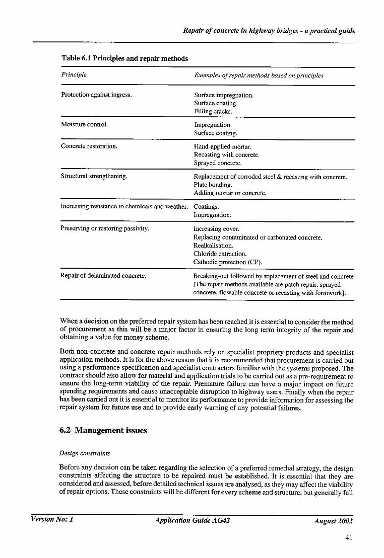
Repair o f concrete in highway bridges - a practical guide
Table 6.1 Principles and repair methods
Principle Examples of repair methods based on principles
Protection against ingress. Surface impregnation. Surface coating. Filling cracks.
Moisture control. Impregnation. Surface coating.
Concrete restoration. Hand-applied mortar. Recasting with concrete. Sprayed concrete.
Structural strengthening. Replacement of corroded steel & recasting with concrete. Plate bonding. Adding mortar or concrete.
Increasing resistance to chemicals and weather. Coatings. Impregnation.
Preserving or restoring passivity. Increasing cover. Replacing contaminated or carbonated concrete. Realkafisation. Chloride extraction. Cathodic protection (CP).
Repair of delaminated concrete. Brealdng-ont followed by replacement of steel and concrete [The repair methods available are patch repair, sprayed concrete, flowable concrete or recasting with formwork].
When a decision on the preferred repair system has been reached it is essential to consider the method of procurement as this will be a major factor in ensuring the long term integrity of the repair and obtaining a value for money scheme.
Both non-concrete and concrete repair methods rely on specialist propriety products and specialist application methods. It is for the above reason that it is recommended that procurement is carried out using a performance specification and specialist contractors familiar with the systems proposed. The contract should also allow for material and application trials to be carried out as a pre-requirement to ensure the long-term viability of the repair. Premature failure can have a major impact on future spending requirements and cause unacceptable disruption to highway users. Finally when the repair has been carried out it is essential to monitor its performance to provide information for assessing the repair system for future use and to provide early warning of any potential failures.
6.2 Management issues
Design constraints
Before any decision can be taken regarding the selection of a preferred remedial strategy, the design constraints affecting the structure to be repaired must be established. It is essential that they are considered and assessed, before detailed technical issues are analysed, as they may affect the viability of repair options. These constraints will be different for every scheme and structure, but generally fall
Version No: 1 Application Guide A G43 August 2002
41

Repair o f concrete in highway bridges - a practical guide
into the following broad categories, though not all of them will apply in all cases:
• Technical;
• Geometric;
• Access/Temporary works;
• Traffic;
• Roadspace availability/Other works;
• Environmental;
• Third party consultation;
• Health and safety;
• Aesthetics;
• Political issues/Public views/Publicity;
• Costs;
• Type of contract;
• Ongoing liabilities.
Technical
A prime factor in developing a concrete repair remedial scheme will be to utilise the data obtained through inspection, testing and structural assessment, to determine the cause of the defects or deficiencies. Without an examination of the causes, the devised solution may not be fully effective, and durable. These causes may he the result of internal problems with materials, external environmental effects or most likely a combination of the two. It is also important to determine the rate of deterioration in the structure, and if possible when the deterioration commenced, or was first observed.
In considering a particular repair technique it may be necessary to carry out further specialised testing, to assess the effects of the work on the global structure and the structural element under repair. Where significant quantities of concrete are to be removed during the repair process, structural implications must be assessed. This may entail placing limitations on the amount of concrete to be removed, phasing the works to limit the effects, and requirements for temporary structural support. Traffic effects, such as loading and vibration, on newly placed concrete must also be considered, and requires careful assessment of traffic management and restrictions. Some works where there are significant structural implications and public safety issues will require technical approval.
It is also important to assess the extent of the required work in advance. Whilst this is not always possible or practical, it is generally worth undertaking all testing in advance to ensure that there are 'no surprises' during the construction work and there can be confidence in the scope of the remedial work, timescales and costs.
When specialist materials and methods of working are being considered it is worth consulting in advance with suppliers and contractors with the requisite expertise. In some cases such as cathodic protection it is essential to have the necessary expertise in-house or available from an independent source, to assist with technical advice, drawing up contract documentation, assessment of tenders and site supervision.
Version No: 1 Application Guide AG43 August 2002
42
Repair o f concrete in highway bridges - a practical guide
Geometric
The location of the structure, its size and position may influence the type and method of repair to be adopted, as well as access to the structure, and the form of temporary works to be utilised.
The road, railway, river or canal carried or crossed by the structure must be considered. In particular the gradient and curvature of roads and proximity of junctions and interchanges may affect the traffic management, and hence place limitations on the form and extent of the proposed remedial measures. The proximity to railway lines, rivers and canals should also be taken into account. Horizontal and headroom clearances may impose additional restrictions, on the type of work to be undertaken and its timing.
Access~Temporary works
The geometry of the structure, and nature of the remedial work proposed, will influence the arrangements required for safe access, mad the type of temporary work required. In some cases, access difficulties and temporary works may limit the viable remedial options available, and in difficult cases entirely govern the type of repairs undertaken. Where temporary works are a significant issue, it may be worth considering alternative methods of procurement such as Design and Build, where advantage can be taken of contractors expertise in design of falsework, access and supports, and to ensure the interaction between and compatibility of the temporary and permanent works.
Traffic
This is a major consideration that affects the planning, design and construction of remedial works on all highway structures. The traffic volumes, speeds and composition (particularly HGVs), and variations through the day, week and year will influence the traffic management requirements, and hence the works proposed. Proximity of the traffic to the structure must also be considered. Early consultation with the Police, highway authorities and other transport undertakings is essential.
Due consideration must be given to the traffic both on and under bridges and the highway authorities consulted. Safe and unhindered access for construction traffic is another issue, including site personnel, and delivery and disposal of materials.
A related issue is the development of the traffic management scheme, and to ensure that it is viable. Discussions with the Police and other authorities will usually be necessary. Phased traffic management to fit in with different stages of the works require particular care. Advance warning signs and diversion route signs must be considered as with the provision of a free breakdown recovery service.
Traffic restrictions will usually require the publication and making of Traffic Regulation Orders, and this may have implications for programming the scheme, and possibly on the type and nature of the works envisaged.
Roadspace availability~Other works
The limitations imposed by traffic and other operations on the road may affect the remedial measures. Interaction and potential for interference between different maintenance operations should be assessed during the design process. This may involve discussions between different highway authorities particularly where very restrictive or disruptive traffic management measures are necessary, or traffic diversions are proposed. Consideration should be given to combining works together to limit traffic disruption to a minimum.
Roadspace availability should be checked at an early stage in the design process, and should be booked in advance. Railway possessions are a particular example and usually require scheduling a long time in advance. Consideration will need to be given to limiting the work to particular periods, eg ovemight
Version No: 1 Application Guide AG43 August 2002
43

Repair o f concrete in highway bridges - a practical guide
working, weekends, avoiding Summer holidays. In some cases this will entail using alternative methods of working or types of repair rather than the most technically feasible solution. Every effort should be made to make a realistic assessment of the time required for the works.
Environmental
Some forms of repair are sensitive to the prevailing environmental conditions. Temperature, relative humidity, wind force and direction, and rainfall may be important issues. The resultant effects on the condition of the concrete substrate will require consideration. The location of the structure in proximity to or within significant environments eg. marine, rivers, hazardous wastes, industrial areas etc. will require special advance investigation. Underground activities such as mining may alter the design of remedial works.
The results of the environmental assessment may result in requirements in the contract documentation for special measures for protection from the elements such as enclosures, sheeting and heating. There may also be other environmental restrictions such as temperature limitations for working with particular materials, and surface dryness of concrete substrates.
The methods of working proposed may necessitate the introduction of additional measures to protect the local environment and deal with waste materials. Special care needs to be taken with operations such as grit blasting, water jetting, sprayed concrete, silane impregnation and the use of other coatings in terms of potential impact on the environment.
Health and Safety
Clearly Health and Safety is an issue affecting all forms of remedial work and should be assessed at an early stage. There are many issues including working in proximity to traffic, use of traffic barriers, safety zones, access for personnel, plant and materials, use of materials, disposal of wastes and screening. Compliance with the relevant safety Regulations will be required, as well as all other relevant legislation.
Third party consultation
When planning remedial work it is essential that, where necessary, there is detailed consultation with third party organisations that might be affected by the works. Examples are Railtrack, London Underground, British Waterways Board, River Authorities, Drainage Boards, Service Companies (electricity, gas, water, telephone, petrol, etc.) Heritage and nature organisations, Local Highway Authorities, Police, Fire Service and Ambulance. Transport operators such as bus and train companies may also need to be consulted. This list is not intended to be exhaustive, but to serve as an example.
Such consultations should take place as early as possible in the design process as they may affect the nature and detail of the work permitted and the timing. Pm'ticular examples can be sited where works in proximity to railway tracks require advance booking of track possessions, negotiation with signalling engineers, civil engineers, the Railway Inspectorate and possibly with train operating companies themselves. Service companies who have facilities in, on or close to the structure that may be affected by the works, and their requirements may influence the type, nature and duration of the contract.
Early consultation with the Police will be necessary, in planning the road closures and traffic management that can be operated safely. Special considerations may need to be made where work is undertaken that has significant effects on local people - such measures as provision of temporary bus services, temporary housing of inhabitants have been used in exceptional circumstances.
Work on listed structures and those in Conservation Areas raises additional issues, and it essential that prior approval and consents are obtained from the appropriate authorities.
Version No: 1 Application Guide AG43 August 2002
44

Repair o f concrete in highway bridges - a practical guide
Where remedial works may effect flora and fauna, special care is required, which may require advance consultation with English Nature, local farmers and special interest groups. Some structures may have bat and bird boxes, or other provisions and the implications will need to be considered. Structures located in Sites of Special Scientific Interest must be handled with cm'e, to ensure minimal impact.
Aesthetics
When considering remedial works options, an issue which should be considered, is the finished appearance of the final scheme, particularly in environmentally sensitive locations. This may require advance approval of the types and sources of materials, finishes and colours to be used, by Planning Authorities, English Heritage and other interested bodies.
Political issues~Public views~Publicity
Consideration should be given to the necessity to consult/inform/seek views from MEPs, MPs and local councillors and the public, particularly those people whose property, business and travel arrangements may be affected by the works. It is advisable to assess the need for and type of publicity required at an early stage in the design process.
Costs
In determining the preferred remedial option, costs should be assessed. It is highly desirable to consider the whole life effects of works, especially as a means for comparison between repair strategies.
Type of contract
Consideration of the type of work proposed and the preferred form of contract should be assessed during the design process. Some forms of work may warrant different forms of contract. Design and build is an obvious example where best use can be made of contractors expertise with design of temporary works. Important considerations in selecting the form of contract are the assessment and apportionment of risks, and the encouragement and development of quality and innovation.
In some instances it will be necessary to impose restrictions on the contractor in the form of lane rental or occupation charges. Incentives can be built into the contract to encourage early completion of the works.
Ongoing liabilities
In making decisions about the appropriate repair options it is essential to consider ongoing liabilities (if any). For instance a cathodic protection scheme will incur ongoing management costs to operate the system, to train staff, and to replace components in due course, whether as a result of deterioration or malicious interference. Issues such as the siting of remote monitoring systems, may need to be changed if office locations alter in the future. Straightforward concrete repairs may also be accompanied by enhanced future monitoring of the structure.
Any repair option must be considered in terms of an ongoing maintenance and management strategy, for the structure concerned, the length of road on which it is sited (including other structures which may or may not be of similar design) and the local and regional road network. Decisions made now may affect future considerations. Periodic small scale repairs may delay the onset of corrosion and the need for major works, but it may not be the most effective strategy. Equally a major break-out and repair proposal may not be cost effective, due to prolonged traffic disruption and a shorter duration smaller scale work combined with cathodic protection may be preferable. Clearly any strategy should also recognise known changed future circumstances - increased traffic as a result of new road schemes, industrial and residential development, reduced traffic due to a bypass or detrunking, adjacent major works or other commitments to avoid roadworks on a length of road.
Version No: 1 Application Guide A G43 August 2002
45
Repair o f concrete in highway bridges - a practical guide
7 NON CONCRETE REPAIR OPTIONS
7.1 Introduction
As an alternative or in combination with the conventional repair, a number of options not based on concrete replacement could be cost effective in certain situations. The main objective of these options is to reduce the rate of steel corrosion, as it is one of the major contributors to the deterioration of steel reinforced concrete. It is, therefore, vital that early signals indicating changes in concrete chemistry are detected during the on-going inspection programme. The important indicators in terms of steel corrosion include increase in chloride content, carbonation and reduction in pH of concrete. Failure to detect these chemical changes early, and allowing severe steel corrosion and the associated physical damage to the concrete will impede the effectiveness of the chosen option. In the following sections the options available are outlined and wherever possible the criteria for their selection is presented. The options are:
• Surface treatments.
• Electro-chemical techniques.
• Strengthening using plate bonding techniques.
A comparison of the methods (and their relative costs) for minimising reinforcement corrosion are given in Table 7.1 and 7.2 respectively.
7.2 Surface treatments
Surface treatments are often used as a preventive maintenance method. However, they can also be used in conjunction with other repair techniques to prevent the reoccurrence of problems. Surface treatments largely fall in to three groups; coatings, surface impregnants and corrosion inhibitors.
Coatings:
Coatings are physical barriers, which prevent ingress of chlorides and carbon dioxide, and which allows concrete to breathe and thereby reduces its moisture contents. In addition to economic requirements such as ease of application, ease of overcoating and long service life, the selection criteria of the barrier coatings can be summarised as follows:
• Chemical resistance (e.g. to salt).
• Diffusion resistance (e.g. to water, CO,_. O_,, chloride ions).
• Weathering resistance (e.g. to UV light, variable temperature and humidity, water).
• Resistance to expansive forces (e.g. to freezing and thawing, alkali aggregate reaction).
• Aesthetic appearance.
• Crack bridging ability.
• Adhesion strength.
• Abrasion resistance.
Version No: 1 Application Guide AG43 August 2002
47

Repair o f concrete in highway bridges - a practical guide
Some earlier examples of coating utilising paint systems not meeting the above criteria have not performed adequately. As a consequence use of paint as a repair option is very rare.
Surface impregnants:
The surface impregnants are generally low viscosity liquids that penetrate the concrete and line the pores. They are colourless with no effect on the appearance of the structure. They are water or alcohol soluble hydrophobic materials which repel water and water-containing chloride salts. They do not block the pores of the concrete and allow it to 'breath' water vapour and other gases which otherwise would remain trapped within the structure. The majority of commercially available materials are silanes, siloxanes or silicone resins.
Silanes become reactive in the presence of moisture and the reaction is governed by the pH of concrete. While the reaction is taking place the volatile silane will continually evaporate and to maximise the success, it is necessary to use very high concentration of silane. It is not necessary to remove old silane when treatment becomes necessary. Silanes are one of the least expensive types of corrosion control maintenance. Their effective life is not known but it could be as much as twenty years. The main disadvantage of silane is that it is harmful to the environment because of its vapour and absorption of excess material by the soil in which the structure stands. Consequently vigorous health and safety precautions should be instigated when using silane. Solutions of silane in water and immobile aqueous emulsions are now available which largely eliminate these environmental problems.
The silanes specified in BD 43/90 for use on HA structures are Isobutyl trimethoxy sitane and Isobutyl triethoxy silane. For impregnants not currently specified by the HA, a test developed by Calder and Chowdhury (1996) can be used to evaluate their performance. Because of the wide variety of structures and the fact that not all parts of a structure are equally at risk from chloride attack, the advice note BA 33/90, 'Impregnation of concrete highway structures' provides guidance as to where and when silanes should be applied.
Siloxanes are described as oligeomeric alkylalkoxysiloxanes. They have all the advantages of silanes with respect to reactivity and water repellancy. However, they have tow vapour pressure and under very dry conditions exhibit less penetration than silanes.
Corrosion inhibitors
A corrosion inhibitor, in the present context, is a substance which when added to the corrosive environment, in this case, chloride-contaminated pore solution around the steel, reduces the rate of the metal dissolution. The inhibitors are classified as cast-in or migrating types. These materials are soluble salts that are incorporated in the concrete at the construction stage, to repair concrete during refurbishment, or as surface application on mature concrete.
There is no general theory of corrosion inhibition in concrete because the mechanism is dependent to a large extent on the particular inhibitor. One basic concept is the formation of stable compounds, which are adsorbed or precipitated on the metal surface. This hinders corrosion reaction either at anodic or cathodic region of the steel. The cast-in type of inhibitors do not influence the ingress of corrosive substances and do not begin to function until these have reached the steel which may take several years.
Inhibitors are divided into according to application and type of corrosion process that is anodic, cathodic or mixed. There are various opinions expressed for their effectiveness, however each inhibitor should be examined on its merit under conditions of application and use.
Methods for the treatment as a repair option include impregnation by ponding, implantation into drilled cavities and electric injection under a potential gradient. Ponding and implantation rely on diffusion of inhibitors through the cover concrete. The speed at which diffusion occurs will depend on the porosity and on the degree of concrete saturation. Migrating corrosion inhibitors (MCI), which are
Version No: 1
48
Application Guide AG43 August 2002

Repair o f concrete in highway bridges - a practical guide
effectively 'mixed' anodic and cathodic inhibitors, are reputed to diffuse through the cement paste in the vapour phase, which assumes that the concrete is only partially saturated up to the depth of the reinforcement. MCIs are said to migrate through the concrete pores, form a monomolecular protective layer and are absorbed physically onto the metal surface. These materials are based on inhibitors that are known to be effective in stopping corrosion on bare steel hence the most critical feature of their performance on reinforced concrete is how quickly they migrate through the concrete to generate a concentration at the reinforcement sufficient to stop corrosion. The evidence to date suggests that these inhibitors (a) can only migrate at a sufficient speed through poor quality concrete with a water to cement ratio greater than 0.6 and (b) cannot accumulate in sufficient quantities near the reinforcement to provide protection when the total chloride concentration exceeds about 1% by weight of cement.
It has not yet been established whether migrating inhibitors can readily stop or substantially reduce the rate of ongoing corrosion; they may only provide additional protection against corrosion initiation. It appears, therefore, that migrating inhibitors are only effective in a limited number of situations. They are however of relatively low cost, although their effective life is not known.
A variety of organic and inorganic substances has been tested which inhibit metallic corrosion in the concrete environment. The inorganic inhibitors include borate of sodium, calcium or zinc, nitrite of sodium or calcium, nitrates of sodium, calcium or potassium. The organic inhibitors are based an amino-alcohol, amine or carboxylic acid radical.
7.3 Cathodic protection (CP)
Introduction
Traditional repair techniques necessitate removal of all concrete contaminated beyond a particular chloride content to be durable. An alternative approach is to use cathodic protection (CP). This involves the application of a small electrical current into the concrete and onto the reinforcement. This inhibits further corrosion. CP is a particularly attractive option as it does not require the removal of chloride contaminated but otherwise sound concrete, and should prevent further corrosion even when exposure to chlorides continues. CP is a specialised technique and requires the services of specialised contractors for installation of systems.
Direction of current flow
Cathode (reinforced bar)
Figure 7.1 Schematic diagram showing application of CP
Version No: 1 Application Guide AG43 August 2002
49

Repair o f concrete in highway bridges - a practical guide
Cathodic protection mechanism
The corrosion mechanism of steel in concrete is electrochemical. Metal ions pass into solution at anodic areas liberating electrons into the metal. These electrons are consumed at cathodic areas in reactions such as the reduction of oxygen and water to form hydroxyl ions. The electrochemical circuit is completed by the pore water electrolyte.
Metal loss (ie corrosion) only occurs at anodic areas. In cathodic protection corrosion is prevented by applying a current from a separate anode so that all the reinforcement to be protected is rendered a cathode and therefore does not corrode. The protection current can be provided by using an external anode of a more reactive metal (sacrificial anode cathodic protection) or by applying a current from a DC supply through an inert anode (impressed current cathodic protection).
With a sacrificial anode system there is little control over the level of CP applied; this will be dictated by the sacrificial anode material and the circuit resistance. Sacrificial systems have had limited use in the UK and are considered experimental. However, research is in progress and there are new systems coming into market. An impressed current system allows the level of CP current to be controlled by the amount of current supplied and is the system generally for bridges. Current is generally supplied from the mains using a transformer/rectifier to provide a DC supply.
Structures suitable for cathodic protection
CP is considered mainly as a repair option for concrete structures corroding as a result of chloride contamination. It is not precluded from use on carbonated structures but the higher resistivity of carbonated concrete requires higher driving voltages and its use would require more careful consideration against other repair options. It is also questionable whether it should be used on prestressing wires. Under certain conditions CP can result in hydrogen evolution which might lead to embrittlement. Use of CP on prestressed steel would require very careful control of the steel potentials which are generated during the process. Earlier concerns that CP might aggravate alkali aggregate reaction or lead to a reduction in bond strength are now considered to be unfounded provided the CP installation operates within standard limits.
It should be borne in mind that CP will at best do no more than minimise further deterioration of a structure. It is therefore important to to establish that structural integrity has not been impaired.
CP ms~l~tion
For CP to be effective the metallic component to be protected must be electrically continuous and in an electrolyte of high enough conductivity to conduct the current from the CP anode to the steel. Reinforcement is generally assumed to be electrically continuous from rubbing connections and tie wires but this needs to be verified/rectified before application of CP systems. Provided corrosion of the reinforcement has not impaired structural integrity, only minimal concrete repairs are required before installation of a CP system. There is no need to remove sound but chloride contaminated concrete. The object of the repairs is to provide a firm surface for the application of the CP anode. Therefore delaminated areas must be detected and repaired. It is also important to ensure that there is adequate concrete cover so that short circuits between the external anode and the reinforcement are avoided. The resistivity of the repair material is also important so that current distribution is as uniform as possible. Resistivity of repair materials should be matched to that of the original concrete.
The relatively poor electrical conductivity of concrete means that the CP anode has to be applied to the entire concrete surface above the steel to be protected in order to minimise the electrical pathway to the steel. A range of anode types have been used and others may be developed. Some of the main types of anode are described below:
Conductive Coatings are basically paint coatings loaded with a conductive pigment such as carbon. A cosmetic/protective top coat is sometimes applied over the conductive coat.
Version No: 1 Application Guide AG43 August 2002
50
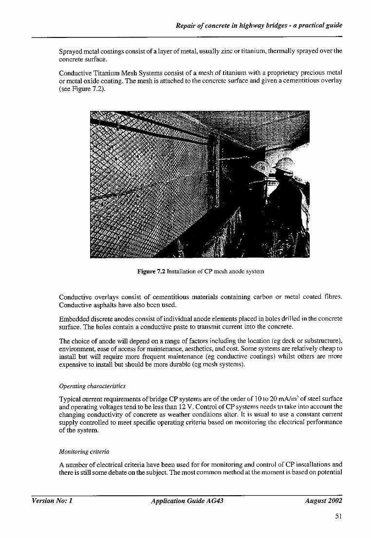
Repair o f concrete in highway bridges - a practical guide
Sprayed metal coatings consist of a layer of metal, usually zinc or titanium, thermally sprayed over the concrete surface.
Conductive Titanium Mesh Systems consist of a mesh of titanium with a proprietary precious metal or metal oxide coating. The mesh is attached to the concrete surface and given a cementitious overlay (see Figure 7.2).
Figure 7.2 Installation of CP mesh anode system
Conductive overlays consist of cementitious materials containing carbon or metal coated fibres. Conductive asphalts have also been used.
Embedded discrete anodes consist of individual anode elements placed in holes drilled in the concrete surface. The holes contain a conductive paste to transmit current into the concrete.
The choice of anode will depend on a range of factors including the location (eg deck or substructure), environment, ease of access for maintenance, aesthetics, and cost. Some systems are relatively cheap to install but will require more frequent maintenance (eg conductive coatings) whilst others are more expensive to install but should be more durable (eg mesh systems).
Operating characteristics
Typical current requirements of bridge CP systems are of the order of 10 to 20 mA/m 2 of steel surface and operating voltages tend to be less than 12 V. Control of CP systems needs to take into account the changing conductivity of concrete as weather conditions alter. It is usual to use a constant current supply controlled to meet specific operating criteria based on monitoring the electrical performance of the system.
Monitoring criteria
A number of electrical criteria have been used for for monitoring and control of CP installations and there is still some debate on the subject. The most common method at the moment is based on potential
Version No: 1 Application Guide A G43 August 2002
5I
Repair o f concrete in highway bridges - a practical guide
decay. As a CP current is applied, the potential of the steel, measured against a standard reference cell, becomes more negative. If the CP current is turned off the potential will 'decay' towards more positive values. Once the CP system is fully energised, a decay of 100 mV from the 'instant off' potential (this is the potential measured within about 0.5 seconds of the current being turned off - this eliminates measurement errors in the steel potential caused by the CP current flow) over 24 hours is considered to indicate adequate performance. It is usual to use reference cells embedded in the concrete at the time of CP installation. The monitoring can be carried out manually or automatically as part of the overall CP control system. Some systems are modem linked to a central control. It is also desirable to monitor the driving voltage required to maintain the target CP current. Increasing driving voltage results from increasing circuit resistance and indicates deterioration in anode performance.
Maintenance
To be effective CP needs to be applied continuously. Hence the anode systems need to be regularly maintained to ensure continuing protection. Frequency of maintenance will depend on the type of anode system used. Hence it is important to consider maintenance costs when choosing the anode system.
Future development
An HA advice note (BA 83/02) has been published. It was developed in conjunction with Corrosion Prevention Association (CPA). CPA has produced a useful reports and monographs on CP.
7.4 C h l o r i d e e x t r a c t i o n
Introduction
Chloride extraction is similar to CP in that it involves the application of an electric current onto the reinforcement. However in this case the current density is higher. Under the influence of the electric field, anions such as chlorides are attracted towards an external anode positioned in an electrolyte on the concrete surface and are eventually extracted into the electrolyte (see Figure 7.3). In addition chemical reactions at the reinforcement increase the hydroxyl ion concentration. Together these actions should re-establish non corrosive conditions in the concrete. Unlike CP this is a one-off treatment requiring only temporary installation of the anode and electrical supply. As in the case of CP, chloride extraction is a specialised technique and requires the services of specialised contractors for installation of systems.
Structures suitable Jbr chloride extraction
Chloride extraction intended for use on chloride contaminated concrete. The process is most effective in removing chloride from the zone between the first layer of reinforcement and the surface; In general, chloride extraction is effective in removing about 70% of the chloride from the cover zone so the level of chloride remaining will depend on what was there originally. At the moment there is no universally agreed target chloride level after chloride extraction that ensures continuing passivity - partly because the passivity is dependent upon a combination of the reduced chloride level and the increased alkalinity. It will not be, however, particularly effective in removing chloride from behind the first layer of reinforcement. Hence the chloride distribution is important in deciding whether a contaminated structure is suitable for treatment. It is not recommended for use on prestressing wires. Problems from hydrogen evolution - mentioned earlier in relation to CP - are far more likely to occur because of the more high potentials generated during chloride extraction. There is also an increased risk of initiating alkali aggregate reaction (AAR) because of the increasing pH from hydroxyl ion production and migration of alkali metal ions towards the reinforcement. Some investigations have shown that AAR can be aggravated whereas others have not. A careful evaluation of the aggregate type (susceptible or not to AAR), and existing alkali levels in the structure, particularly the effect of sodium ions from
Version No: 1
52
Application Guide A G43 August 2002

Repair o f concrete in highway bridges - a practical guide
Direction of current flow
Pla:
Figure 7.3 Schematic diagram showing arrangement for desalination process
chloride contamination, needs to be carried out before chloride extraction is recommended.
As in the case of CP, chloride extraction will at best do no more than minimise further deterioration of a structure. It is therefore important to establish that structural integrity has not been impaired.
Pre-installation procedures
It is important that current is applied evenly over the surface of the concrete. Hence the reinforcement must have electrical continuity, and cracked, spaUed or delaminated areas need to be repaired. The concrete should be sampled to establish chloride profiles although this might have already been carried out as part of the inspection procedures indicating that repair is needed. A half cell potential survey also provides useful information as potentials should become more positive after treatment. However see note of caution in section 'POST TREATMENT'.
Installation and operating characteristics
The external anode/electrolyte combination is usually a titanium mesh immersed in potable water or saturated calcium hydroxide solution. The latter electrolyte helps maintain a high pH such that chlorine gas - a possible health hazard in enclosed areas - is not evolved at the anode. Steel mesh can also be used but, although cheaper, will corrode during the process and could stain the concrete surface. The electrolyte is contained in reservoirs attached to the concrete surface. Other methods of electrolyte containment have also been used such as cellulose fibre sprayed over an anode mesh positioned a short distance above the concrete surface using wooden battens. Electrical connections are made to the steel reinforcement and the anode mesh and DC current applied - generally using a transformer/rectifier. Current is applied at 1 to 2 A/m'- of concrete surface for a period of 4 to 8 weeks. The total charge applied should not exceed 1500 A.hours/m-' of concrete surface. It is usual to apply the process in specific electrically separate zones so that current spread over the structure can be controlled.
The progress of the treatment is monitored by taking concrete cores or dust samples for chloride analysis generally after a few weeks of the treatment. Using information on the original chloride levels in the concrete this allows an estimate of the total chloride extraction time needed to be made. Further sampling may be carded out after a further period. The chloride extraction will be terminated when the process has resulted in chloride levels reaching a previously decided objective. The progress of the chloride extraction can also be monitored by analysis of the chloride content of the electrolyte.
Version No: 1 Application Guide A G43 August 2002
53
Repair o f concrete in highway bridges - a practical guide
Post treatment
Chloride extraction does not confer the permanent protection offered by CP. The passive conditions established by chloride extraction could be lost if, say, there was scope for redistribution of chloride within the structure from zones not affected by the chloride extraction, or exposure to chlorides continued. In such cases it would be necessary to monitor for the onset of renewed corrosion using standard methods. However the standard electrochemical test methods such as half cell potentials and corrosion current measurements should be used with caution. The chloride extraction process polarises the steel to very negative values and these can persist for some time once the process is terminated. For example the half cen potentials that were originally about-300 mV v AgC1 could fall to - i V during chloride extraction. After chloride extraction the potentials could rise to values around 0 indicating passive steel. However the rate of change varies. In some laboratory trials passive potentials were apparent within a few weeks of treatment (Patel and McKenzie, 2000); in some site trials potentials remained apparently active for several months (Armstrong et aL, 1996). Hence early monitoring could give a misleading impression. Similarly corrosion current measurements rely on the potential being relatively stable; it is also possible that the large changes to the concrete chemistry render such measurements inappropriate for structures where chloride extraction have been used. The use of corrosion current measurements for corrosion monitoring generally is an area of ongoing research.
7.5 Realkalisation
Introduction
Realkalisation is a similar process to chloride extraction but is used on carbonated concrete. A DC current is applied to the reinforcement from an external anode in an electrolyte of an alkali metal on the concrete surface. This raises the pH of the concrete back to passive levels by a combination of migration of alkali metal ions from the electrolyte into the concrete, and generation of hydroxyl ions at the reinforcement. As in the case of chloride extraction it is a one-off treatment requiring only temporary installation of the anode and electrical supply. Current densities used are similar to those used in chloride extraction but the time is shorter - generally only about 2 weeks. Again it is a specialised technique and requires the services of specialised contractors for installation of systems.
Structures suitable for realkalisation
Realkalisation is intended for use on carbonated concrete. Hence it is most important to establish the extent of carbonation (for methods see section 'Pre installation procedures') and confirm whether carbonation is the cause of any corrosion, or is likely to lead to corrosion in the relevant time scale.
The limitations with regard to prestressing highlighted in relation to chloride extraction are also relevant to realkalisation. With regard to A A R the fact that alkali levels are depressed at the start implies that there is more leeway particularly as realkalisation is applied for a shorter period. However there could be increases in alkalinity in areas that are still uncarbonated and this must be considered. Realkalisation on bridge structures is not widely used and expert advice may be useful before considering the use of the technique.
Pre-installation procedures
It is important that current is applied evenly over the surface of the concrete. Hence the reinforcement must have electrical continuity, and cracked, spalled or delaminated areas need to be repaired. The repair material needs to be compatible with the process. Carbonation is often associated with areas of low cover. If the cover is very variable it may be necessary to apply high resistance screeds to areas of particularly low cover to prevent current dumping through such regions. Any surface coatings need to be removed or assessed for likely effects on the process- say by a trial treatment on a test area. Cores should
Version No: 1 Application Guide A G43 August 2002
54

Repair o f concrete in highway bridges - a practical guide
be taken at representative points to establish pre-treatment carbonation and alkali metal ion distributions. Depth of carbonation is usually detected by splitting the core lengthwise to provide a freshly exposed surface then spraying with phenolphthalein indicator. The colour changes from red to colourless as the pH drops below about 10. This therefore classes the concrete into two quite broad bands of pH. More detailed profiles of pH can be obtained using a range of indicators, or by profile grinding the core and measuring pH on water extracts of the concrete dust. Alkali metal ion distribution is established by chemical analysis. It is important to take sufficient cores to assess the variability in carbonation over the whole area of interest.
Installation and operating characteristics
The external anode/electrolyte combination is usually a CP titanium mesh immersed in a 1 molar sodium carbonate solution. If it is considered that introduction of sodium carbonate into the concrete is undesirable from AAR considerations, then calcium hydroxide can be used. Steel mesh can also be used but, although cheaper, will corrode during the process and could stain the concrete surface. The electrolyte is contained in reservoirs attached to the concrete surface. Other methods of electrolyte containment have also been used such as cellulose fibre sprayed over an anode mesh positioned a short distance above the concrete surface using wooden battens. Electrical connections are made to the steel reinforcement and the anode mesh and DC current applied - generally using a transformer/rectifier. Current is applied at 1 to 2 A/m ~- of concrete surface for a period of about 1 to 2 weeks. It is usual to apply the process in specific electrically separate zones so that current spread over the structure can be controlled.
The progress of the treatment is monitored by taking concrete cores or dust samples for sodium ion and pH analysis. Using information on the original levels in the concrete this allows an estimate of the progress being made. The usual aim is to terminate the process once the concrete has been realkalised to the level of the first layer of reinforcement.
Posttreatment
A realkalised structure will still be exposed to the atmospheric CO,_ which resulted in the original carbonation. Hence it would be expected that the problem would eventually reoccur unless concrete cover has been increased as part of the repair process. Depending on the remaining target life of the structure it could be desirable to reduce further exposure to CO,_ by applying an anti-carbonation paint coating. Immediately after treatment the concrete is likely to be saturated. Prior to applying a coating it is necessary to allow a period for the concrete to dry out, or to use a coating specially formulated for application to saturated concrete.
Monitoring realkalised structures for corrosion activity is subject to the same considerations as mentioned for chloride extraction. If an anti-carbonation coating is present this complicates monitoring even more. The inclusion of embedded corrosion monitoring probes bears consideration under such circumstances.
7.6 Strengthening using plate bonding techniques
If structures require strengthening, consideration should be given to establishing viable options, taking into account all the design and other constraints. One such option would be the use of plate bonding techniques, either in the form of steel plates or fibre reinforced composites, to strengthen concrete members against bending or shear deficiencies, or to wrap columns to enhance impact resistance. Often concrete repairs may be required in association with these strengthening operations. Where there is a combination of works, additional measures will be required for concrete repairs, to ensure that the concrete surface is suitable for the plate bonding.
As with all concrete repair works, there should be a pre-contract investigation of the condition of the structure. This should identify deterioration processes likely to affect the performance of the structure
Version No: 1 Application Guide AG43 August 2002
55
Repair o f concrete in highway bridges - a practical guide
within its residual life. Such investigations should include thorough inspection of the concrete surfaces on which the bonding is to be carried out, a visual inspection, an assessment of the concrete strength, chemical analysis and acoustic techniques such as 'hammer tapping' surveys to identify defects.
If defects are identified, repairs should be carried out using an appropriate concrete repair system. As a special requirement cementitious repairs should be cured for at least twenty-eight days before undertaking any subsequent bonding work - this is an issue for special consideration for designers planning or programming works.
Good preparation of the concrete surfaces is of paramount importance to the long term success of the bonding and strengthening operation. Before adhesive is applied the concrete surface must be cleaned so that it is free of laitance, loose material and other contaminants. This applies equally to original surfaces as with any repaired areas. The surface preparation process is important in that it should remove the surface layer to expose small particles of aggregates, without causing micro-cracks or other damage in the substrate. The surface should not be polished or roughened excessively. Sharp edges, shutter marks or other irregularities should be removed to achieve a flat surface. The usual techniques involved include wet, dry or vacuum abrasive blasting, high pressure washing, steam cleaning or for smaller areas, mechanical wire brushing or surface grinding. Generally mechanical methods such as needle gunning and bush hammering are too aggressive.
Minor imperfections or slight unevenness in the concrete surface, can often be treated with epoxy materials which can be applied in thin layers, and the rapid strength gain permits over-bonding to be carried out after a short time. Some bonding systems require the use of a primer on completion of the surface preparation. This primer, which seals the surface should be applied strictly in accordance with the manufacturers instructions, and in the case of repaired surfaces should be compatible with the materials used.
Assessment of surface quality can take the form of a series of pull-off tests (where a surface primer is used, the test should he carried out on the primed surface). The test should be undertaken by means of a 'dolly' based on the test described in BS 188 t :Part 207, and a minimum of three tests completed, to give an indication of the tensile strength of the substrate and the quality of the surface preparation. The concrete surface should be dry for normal applications. Where this is not possible, because of the nature of the stmcture, special consideration should be given to the type of adhesive to be employed. Reference should be made to Concrete Society Report TR55 (2000b).
7.7 Comparison of repair methods
The characteristics of various methods for minimising reinforcement corrosion are given in Tables 7.1 and 7.2.
Version No: 1 Application Guide AG43 August 2002
56
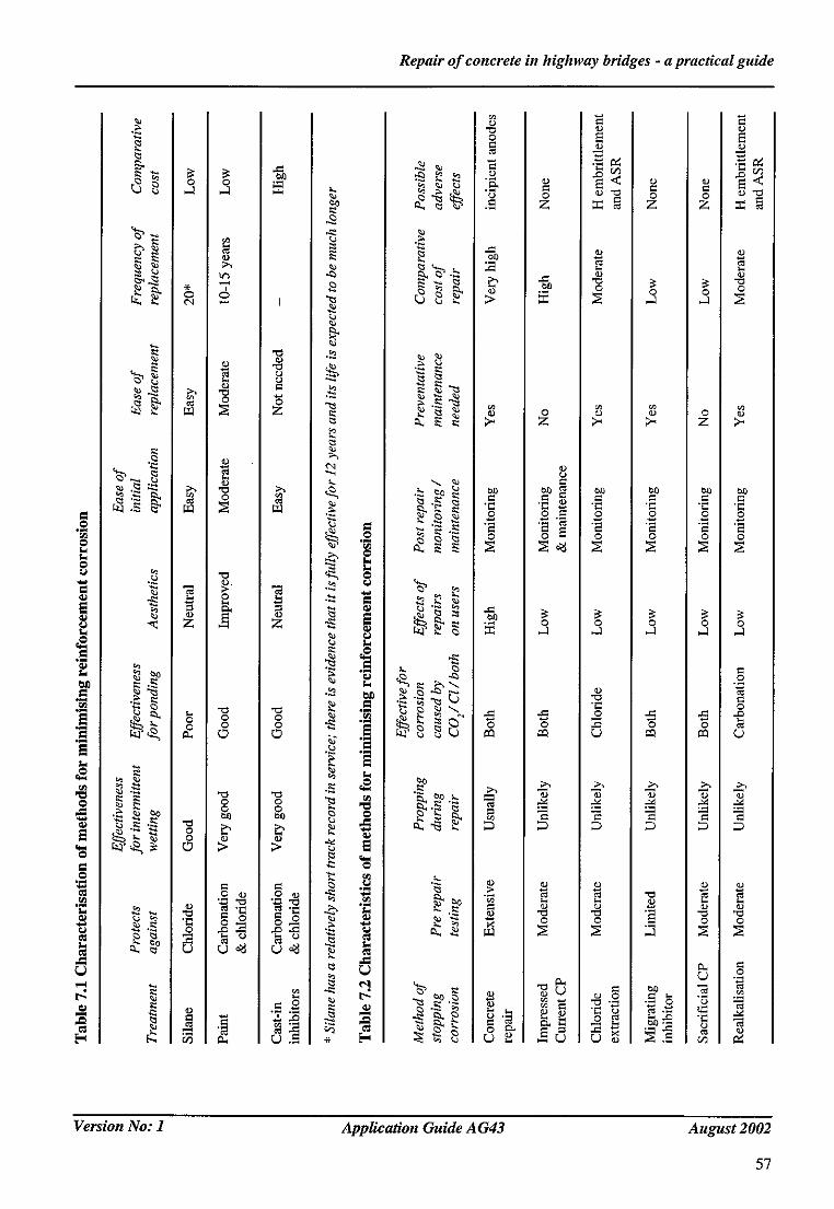
Repair of concrete in highway bridges - a practical guide
.o
.! a
tz a
r~
re3
oJ
"o o
"o o
z ~
0
r )
I
"0 "0
r,1
0
0
¢0
¢xl
a
[ , .
i~2~
\ 8
~ "i
~.~
"0 0
.~ Z
0 0
,.e ,..1
.~, "~
"0
f2~ 0
H <
0
0
0 , 1
" 0
0
r..)
0
© 0
0 Z
0 ,-1
"2 0
0
" 0
H
C z :z:=~
- o C 0
o
m "2 0 0
0 0
0
~ r.)
12, ~ "0 '1~ 0 0
r.) . o
? .!
Version No: 1 Application Guide AG43 August 2002
57
Repair o f concrete in highway bridges - a practical guide
8 CONCRETE REPAIR
8.1 Introduction
Concrete repair work carried out since the early 70s have become somewhat complicated by the Iarge array of different repair processes and methods that have been put onto the market. Earlier repair was carried out using standard Portland cement based mortar, but now materials range from pure polymers such as polyesters and epoxy resins to polymer modified Portland cement based products. Although there may be a temptation to ignore the wide spectrum of materials available simply due to its complexity, and stick to cementitious materials similar to the original substrate, this would make poor engineering judgement due to the advantages provided by the new materials.
A high proportion of current UK expenditure on repair of existing structures is related to the repair of concrete. It may be impossible to specify the life expectancy of a given repair and hence to compare potential repair methods. However, much can be done to increase the chances that a repair will be durable and acceptable in appearance. It is important that when deciding upon and specifying the requirements for a concrete repair, the following points are taken into account and understood if durability and appearance requirements are to be achieved:
• Accurate determination of the condition of the concrete immediately adjacent to the repair through adequate testing prior to the works is vital in providing an extended life to the repair and quantifying the contract to provide realistic cost estimates.
• Choice of material types together with preparation and application methods should reflect the fmal function of the repair.
• Proper use should always be made of trial mixes and site tests generally to determine in particular flow setting time and appearance characteristics.
• Good management practices are required in the handling, mixing, storing, placing and curing of materials.
• Preparation of surfaces prior to repair must reflect the extent and nature of the problem to be rectified and be compatible with the chosen repair material.
• Examination of the structure as a whole should be carried out to ensure that it is operating efficiently, and that defects that may affect repair durability are removed, i.e. blocked drainage paths etc.
The final appearance of any concrete repair is often important, and if this is critical repairs must be carried out sympathetically with the surrounding structure and environment. In areas where appearance is less important such as bearing shelves and other hidden from view the finish specification can be relaxed. The appearance of the repair will depend upon:
• Colour - with present day grout pigments and colour additives it should be possible, with suitable trials, to obtain a satisfactory colour match.
• Texture and standard of finish - with proper material design, tooled finishing and adequate curing the repair can be made to blend into the existing surface finish.
It is almost impossible to obtain a total match of colour and texture. If uniformity of appearance is paramount then a coating or other masking technique may be considered. However, the suitability of the coating and its durability must be carefully assessed. In such cases it is essential to produce a location plan of the repaired areas as an aid to long term monitoring.
Version No: 1 Application Guide AG43 August 2002
59

Repair o f concrete in highway bridges - a practical guide
8.2 Select repair material
Before the repair method can be decided upon, it is essential that the condition of structure is determined using the inspection and investigation techniques described in Sections 3 and 4. Having studied the test results and the causes of deterioration the following options need to be considered:
• No remedial action.
• Concrete repair.
• Non-concrete repair.
• Combination of concrete and non-concrete repair.
The last three options require decisions to be taken on the selection of the best repair option and section 6 offers guidance on this under the heading'selecting the best option'. An option that includes concrete repair will then need further consideration to select the best material to satisfy the particular management issues and repair functionality and durability.
Typical functions are listed below:
• Chloride inhibition.
• Special application.
• Structural performance.
• Cosmetic repair.
• Combination of any above.
Chloride penetration of the original concrete and the consequent corrosion of reinforcement is perhaps the main reason for concrete deterioration and delamination. It is therefore one of the main reasons for carrying out concrete repairs. The repair has generally to function in the same or a similar environment to that which caused failure of the original parent concrete.
The selection of die repair material must take this into account and the absorption properties will be an important parameter in the decision making process. This property can be either intrinsic to the chosen material or induced by the use of coatings such as silanes. Such repairs are also commonly used with non concrete repair techniques like cathodic protection in order to minimise the detrimental effect of any further chloride penetration or incomplete removal of chloride ions already present.
Special applications for concrete repairs occur from time to time often as a result of constraints imposed by traffic and management issues. Unexpected defects found during the course of works such as waterproofing need to be dealt with quickly to avoid contract and traffic management problems. For these types of repair early setting and curing characteristics are important properties which govern the choice of the most suitable material. In fact when carrying out works of this kind unexpected defects should be anticipated and a supply of suitable material should be available on site for immediate use.
With regard to repairs associated with structural performance, the compressive and tensile strength together with the modulus of elasticity will be maj or factors governing the choice of materials. For this type of repair cement based materials are likely to be more compatible with the parent concrete than epoxy or polymer mortars but these generally require longer curing periods. Failure to cure adequately can adversely affect the interface bond so reducing the repair functionality and durability.
Whatever the reason for the required function of the repair the appearance is very important in sensitive high visibility areas. Great care must be taken to achieve cosmetic compatibility with the surrounding
Version No: 1 Applicalion Guide A G43 August 2002
60
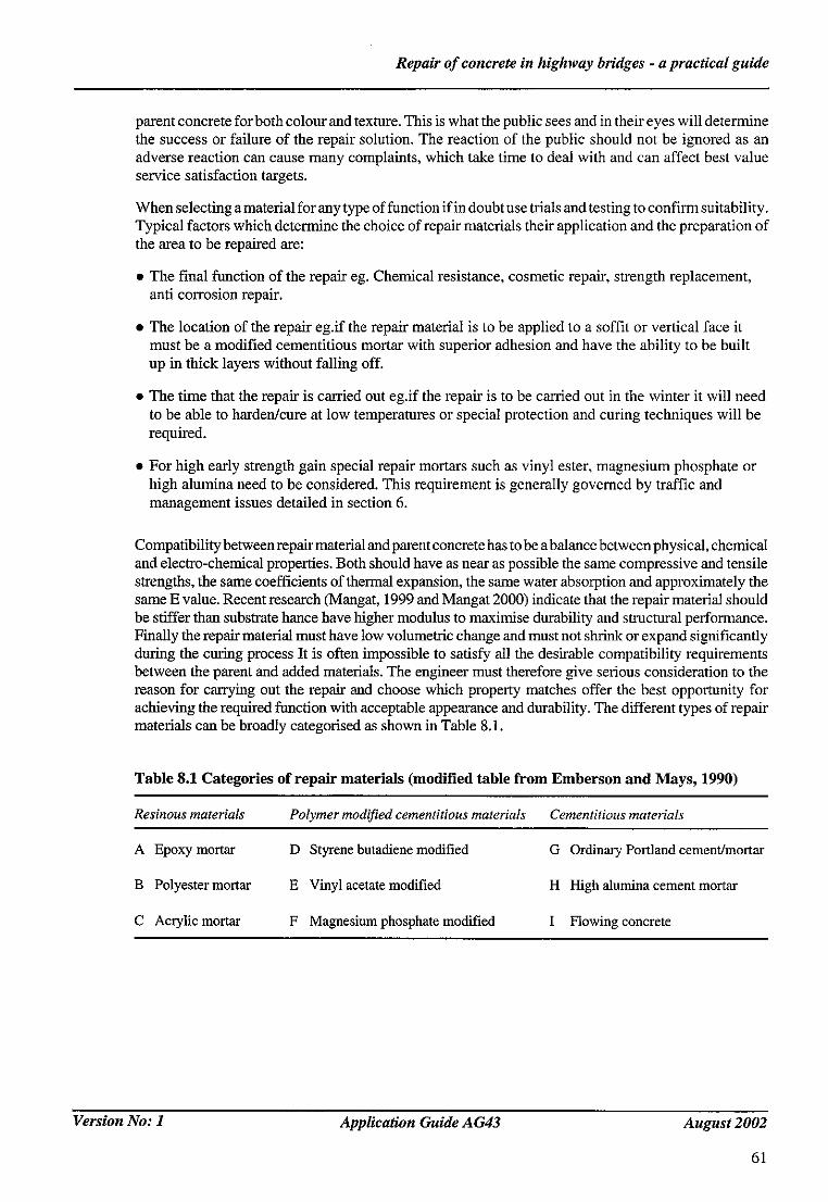
Repair o f concrete in highway bridges - a practical guide
parent concrete for both colour and texture. This is what the public sees and in their eyes will determine the success or failure of the repair solution. The reaction of the public should not be ignored as an adverse reaction can cause many complaints, which take time to deal with and can affect best value service satisfaction targets.
When selecting a material for any type of function if in doubt use trials and testing to confirm suitability. Typical factors which determine the choice of repair materials their application and the preparation of the area to be repaired are:
• The final function of the repair eg. Chemical resistance, cosmetic repair, strength replacement, anti corrosion repair.
• The location of the repair eg.if the repair material is to be applied to a soffit or vertical face it must be a modified cementitious mortar with superior adhesion and have the ability to be built up in thick layers without falling off.
• The time that the repair is carried out eg.if the repair is to be carried out in the winter it will need to be able to harden/cure at low temperatures or special protection and curing techniques will be required.
• For high early strength gain special repair mortars such as vinyl ester, magnesium phosphate or high alumina need to be considered. This requirement is generally governed by traffic and management issues detailed in section 6.
Compatibility between repair material and parent concrete has to be a balance between physical, chemical and electro-chemical properties. Both should have as near as possible the same compressive and tensile strengths, the same coefficients of thermal expansion, the same water absorption and approximately the same E value. Recent research (Mangat, 1999 and Mangat 2000) indicate that the repair material should be stiffer than substrate hance have higher modulus to maximise durability and structural performance. Finally the repair material must have tow volumetric change and must not shrink or expand significantly during the curing process It is often impossible to satisfy all the desirable compatibility requirements between the parent and added materials. The engineer must therefore give serious consideration to the reason for carrying oat the repair and choose which property matches offer the best opportunity for achieving the required function with acceptable appearance and durability. The different types of repair materials can be broadly categorised as shown in Table 8.1.
Table 8.1 Categories of repair materials (modified table from Emberson and Mays, 1990)
Resinous materials Polymer modified cementitious materials Cementitious materials
A Epoxy mortar D Styrene butadiene modified G Ordinary Portland cement/mortar
B Polyester mortar E Vinyl acetate modified H High alumina cement mortar
C Acrylic mortar F Magnesium phosphate modified I Flowing concrete
Version No: 1 Application Guide A G43 August 2002
61

Repair o f concrete in highway bridges - a practical guide
Although cementitious materials will usually have properties closest to the original substrate and therefore provide compatibility, there are many reasons why this type of repair material will not always provide the best solution:
• Thin repairs, usually hand applied to vertical or overhead areas, require better initial bond characteristics and build up characteristics, than cementitious materials will give.
• If the existing concrete has failed due to chemical attack or high wear, then using a polymer resin mortar with higher strength and resistance to chemicals would be appropriate.
• Logistical reasons may require a very quick setting time and early strength gain, in which case resin mortars, e.g. vinylester resins, could be used.
The difference between normal flow (predominantly comprising Portland cement) and high flow (proprietary shrinkage compensated) should be appreciated together with the need to adequately test in trials that the concrete flows adequately. Sprayed concrete - either a designed mix or a proprietary polymer - modified Portland cement mortar - also has unique testing requirements.
Pre-batched, shrinkage compensated polymer modified cementitious or complete polymer mortars with specific bond coats, primers etc., may also be used and these will require strict compliance with the manufacturer's instructions; and site trials should be considered prior to taking a decision on suitability.
8.3 Material properties
The different generic materials in Table 8.1 have significant differences in physical and mechanical properties as compared with the substrate concrete. These properties will vary with time as the processes of hydration and polymerisation progress. The significance of property mismatch between repair material and substrate is not always critical but does depend on the size and location of a patch repair together with its required function. Typical properties for the different types of repair material are given in Table 8.2.
Table 8.2 Typical mechanical properties of concrete repair materials (After Mays and Wilkinson, 1987)
Polymer modified Plain
Resinous cementitious cementitious Property materials materials materials
Compressive strength, MPa 50-100 30-60
Tensile strength, MPa 10-15 5-10
Modulus of elasticity in compression, GPa 10-20 15-25
Maximum service temperature (°C) 40-80 100-300
Coefficient of thermal expansion (per °C) 25-30x10 ~ 10-20x10 "6
Water absorption (% by mass) 1-2 0.1-0.5
20-50
2-5
20-30
>300
10xl0 -6
5-15
Version No: 1 Application Guide AG43 August 2002
62

Repair o f concrete in highway bridges - a practical guide
Whilst strength cherecteristics of the repair material are important and should be similar to the surrounding subtrate as indicated in Section 8.2, the modulus of elasticity is perhaps the most important parameter to the success or otherwise of the repair.
The modulus of elasticity of a patch repair material as compared with that of the substrate concrete may result in a different stress distribution in the element as a whole following repair. This could be important when the repair is in a load carrying zone. Materials with a low modulus value may generate relative high stresses in the substrate concrete as compared with those in the repair material and correspondingly high longitudinal shear stresses at the repair substrate interface, with the consequent potential for bond failures. If bond failures occur as a consequence there may be long-term durability implications. As a guideline, it is recommended that the modulus of elasticity of the repair material lies within the range +10 kN/mm-" of that of the substrate concrete.
The adhesion of the repair material to the concrete substrate is an area in which considerable research has taken place. Of the many surface preparation techniques evaluated, grit blasting and water jetting are both effective. Water jetting will provide a rough, clean and damp surface giving the highest bond strengths so using the repair material properties to maximum effect.
The flexural performance of beams repaired in the tension zone is enhanced by the use ofrelatively high tensile strength repair materials. It is recommended that the tensile strength of repair materials should always be greater than that of the substrate concrete.
Other compatibility factors should also be considered, particularly dimensional, where volume changes can take place without loss of bond and delamination, due to modulus of elasticity, creep and drying shrinkage thermal movement.
Chemical compatibility between existing substrate and repair material should be such that no adverse effects occur, and the repair material should assist in preventing later corrosion of reinforcement within the area of repair with or without the use of reinforcement coatings.
The importance of defining the requirements of water cement ratio/aggregate size/cement content and low heat of hydration cement correctly within the specification will increase the life of the repair. Sulfate resisting Portland cement provides less protection to reinforcement against chloride induced corrosion than other cements. It should only be used to repair reinforced concrete made with sulfate resisting concrete, or not exposed to chlorides.
Specialist situations may require innovative repairs to be carried out such as thin layer repair, or requiring high build materials with specific characteristics, which can only be achieved through polymer modified materials. Other applications such as the repair of ASR affected concrete may require particular additional properties in the repair material - typically the use of low reactivity aggregates. Where repairs are to be carried out in association with another remediation technique such as cathodic protection, the resistivity of the repair materialis important and should be specified. Advice from a cathodic protection specialist should be sought.
8.4 Structural considerations
Concrete repair will always entail removal of parent concrete during the preparation phase. This will affect the performance of the structure to a greater or lesser degree depending on the amount of concrete removed and whether or not the affected member is of primary, secondary or tertiary importance with regard to overall structural stability and carrying capacity.
The engineer must assess the effects of removing concrete and possibly reinforcement in the preparation phase to ensure the integrity of the structure is maintained to prevent the safety of the public and site staff being compromised.
Version No: 1 Application Guide A G43 August 2002
63

Repair o f concrete in highway bridges - a practical guide
This does not necessarily mean that a full, calculated assessment must be carried out on all structures prior to repair. In some instances where the repairs are small and affecting areas or members of low structural sensitivity a subjective assessment based on inspection and engineering judgement may be sufficient. However, if in doubt a full calculated assessment should be carried out. Less experienced engineers should consult more experienced colleagues in determining the appropriate assessment for any particular instance. Great care should also be taken in the application of design and assessment codes of practice in repair situations as they may not always be appropriate.
The assessment whether judgmental or calculated should take account of the following:
• The amount of concrete to be removed and its location.
• The amount of reinforcement to be removed and its location.
• The amount of concrete or reinforcement to be removed at any one time.
• The sensitivity of the location to structural integrity i.e. Is the affected member primary, secondary or tertiary? Is the affected area in a highly stressed zone?
• The need to limit or eliminate live load.
• The need for propping and if considered necessary the response of the structure to such propping.
In addition to their effect on safety during the repair work the last two points above need to be considered as part of the actual repair process. The process and the consequent long term performance and durability of the repair may be sensitive to structural vibrations during the repair material placement and setting phase. Limiting live load and/or the use of propping can control such vibrations.
The installation of load relief systems is both expensive and time consuming while the introduction of traffic constraints has serious impacts on the travelling public. Neither technique should be used as standard practice. Usage should depend on the outcome of the assessment of either safety or required repair conditions.
Preloading a structure or member prior to concrete repair is another technique that has, in some instances, been considered as part of the concrete repair process. It is potentially applicable to areas where the repair is required to act structurally with the parent concrete. Pre-loading may assist to achieve this. It is, however, a specialist area and expert advice should be sought before such techniques are used.
8.5 Breaking out of concrete
Various specifications use different terminology to refer to the concrete that is to be removed. It is not uncommon to find that some people expect 'unsound' concrete to be delaminated, loose or of reduced strength when it may be structurally 'sound' in every respect other than high chloride levels. Whatever criteria are used to establish the extent of concrete to be removed they must be unambiguous. The common expression 'break out to sound concrete' is ill defined.
It is common when repair work commences that much more concrete requires removal than was at first envisaged e.g. the reinforcement is corroded further into the stmcture than allowed for. The designer/ specifier should consider what allowances may have to be made in such a scenario and whether to stipulate a maximum depth of concrete removal before propping or other measures are required.
Breaking concrete out mechanically (shown in Figure 8.1) can create a weak layer or potential failure plane immediately below the broken out surface (sometimes referred to as bruising). This may be adequately removed by grit blasting or hydro demolition but the substrate should be checked for
Version No: 1 Application Guide AG43 August 2002
64
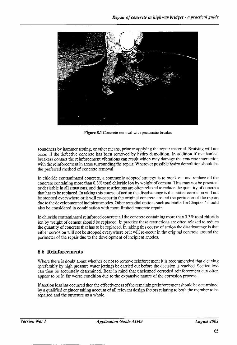
Repair o f concrete in highway bridges - a practical guide
Figure 8.1 Concrete removal with pneumatic breaker
soundness by hammer testing, or other means, prior to applying the repair material. Bruising will not occur if the defective concrete has been removed by hydro demolition. In addition if mechanical breakers contact the reinforcement vibrations can result which may damage the concrete interaction with the reinforcement in areas surrounding the repair. Wherever possible hydro demolition should be the preferred method of concrete removal.
In chloride contaminated concrete, a commonly adopted strategy is to break out and replace all the concrete containing more than 0.3% total chloride ion by weight of cement. This may not be practical or desirable in all situations, and these restrictions are often relaxed to reduce the quantity of concrete that has to be replaced. In taking this course of action the disadvantage is that either corrosion will not be stopped everywhere or it will re-occur in the original concrete around the perimeter of the repair, due to the development of incipient anodes. Other remedial options such as detailed in Chapter 7 should also be considered in combination with more limited concrete repair.
In chloride contaminated reinforced concrete all the concrete containing more than 0.3% total chloride ion by weight of cement should be replaced. In practice these restrictions are often relaxed to reduce the quantity of concrete that has to be replaced. In taking this course of action the disadvantage is that either corrosion will not be stopped everywhere or it will re-occur in the original concrete around the perimeter of the repair due to the development of incipient anodes.
8.6 Reinforcements
Where there is doubt about whether or not to remove reinforcement it is recommended that cleaning (preferably by high pressure water jetting) be carried out before the decision is reached. Section loss can then be accurately determined. Bear in mind that uncleaned corroded reinforcement can often appear to be in far worse condition due to the expansive nature of the corrosion process.
If section loss has occurred then the effectiveness of the remaining reinforcement should be determined by a qualified engineer taking account of all relevant design factors relating to both the member to be repaired and the structure as a whole.
Version No: 1 Application Guide A G43 August 2002
65

Repair o f concrete in highway bridges - a practical guide
Once a decision has been made that new reinforcement should be introduced into the repair there are three usual methods of fixing:
Lapping
Here reinforcement should be fixed as for new build with appropriate lap lengths and tying wire (preferably stainless steel) used. If the size of repair marginally precludes sufficient lap length then individual assessment of the laps may result in a shorter lap requirement. Extending the repair size to accommodate the bars may also be considered. However it should be appreciated that this may not be practicable or economic and can only be assessed on a repair specific basis.
Mechanical connectors"
Mechanical connectors are a very effective method of joining rebars where insufficient lap length is available. The strength of most connectors greatly exceeds the strength of the rebars. The diameter of connectors is greater than that of the reinforcement and difficulties may be encountered if there is reinforcement congestion or limited cover available to accommodate the device. It may of course be possible to enlarge a repair to provide appropriate cover. Consideration should also be given to staggering of the position of the connectors in adjacent reinforcement. Their use is also not recommended in structurally critical areas, where there are high stresses or elements potential subject to fatigue.
Welding
The welding of replacement reinforcement using butt and fillet welds has been successful in many situations. If this option is to be considered then the compatibility of the existing and replacement steel must be established. Welding can reduce the tensile strength of the reinforcement and this must be taken into account. Correct welding procedures and certification are required. It is also important that scrupulous preparation be observed throughout. Testing of the finished welds is strongly recommended.
Other options
If it is not possible or desirable to use any of the foregoing methods of fixing replacement reinforcement then the use of threaded connectors may provide a solution. They are normally only used forconnecting bars where the threading can be carried out away from the structure. In certain cases it may be possible to thread bars insitu however this would require special consideration of each particular case and would generally be regarded as a last option.
8.7 Concrete repair methods
These repairs are normally carried out following removal of cracked and spalled concrete which has been identified as being defective using inspection and investigation techniques described in sections 3 and 4. Removal is generally done using pneumatic/electric breaker or these days increasingly by hydro-demolition if there are numerous areas. In all cases the boundary of the repair should be sawcut using a power-cutting disc. This exposed reinforcement should be cleaned and treated. To ensure there is good bond between parent concrete and the repair material it is usual to cut back behind any reinforced reinforcement by a specified amount. Some manufacturers also require a primer or bonding coat to be applied prior to the application of the repair material. Unless stated otherwise by the manufacturer, the concrete substrate should be thoroughly soaked with clean water for a prescribed period of time.
Version No: l
66
Application Guide A G43 August 2002
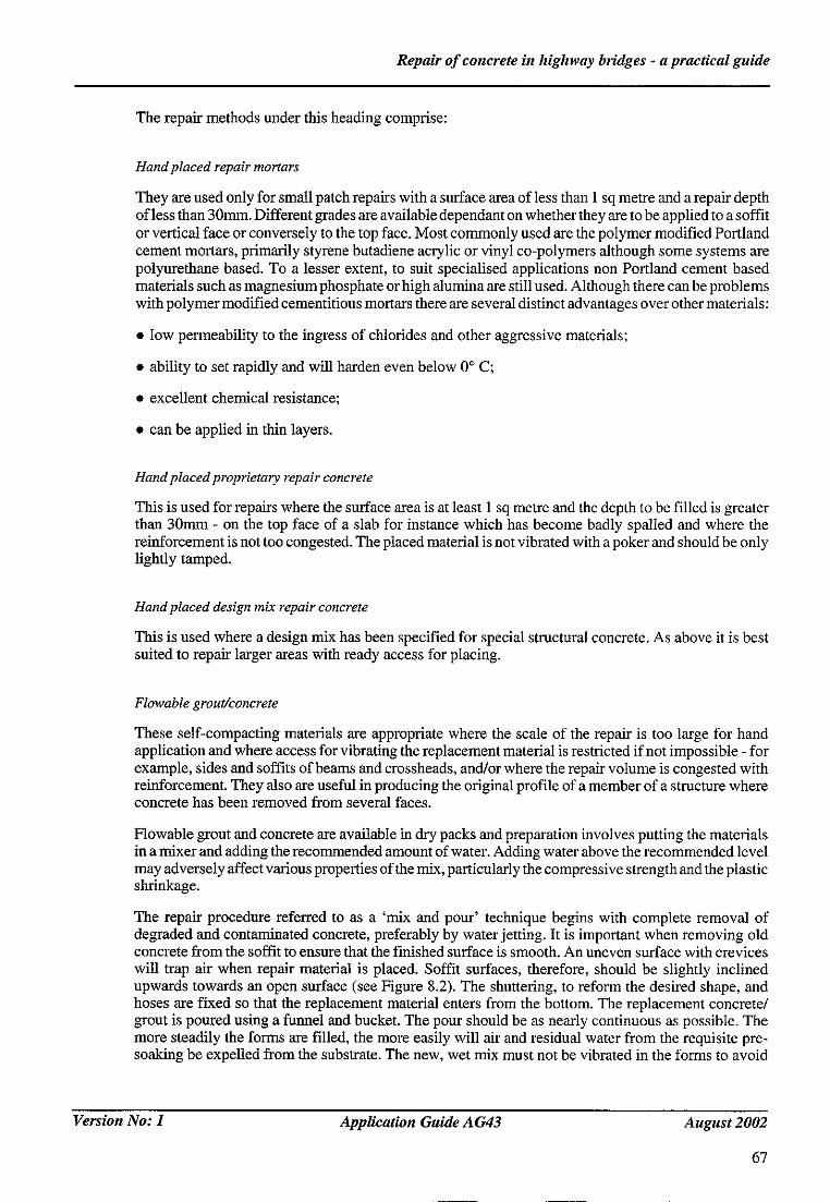
Repair o f concrete in highway bridges - a practical guide
The repair methods under this heading comprise:
Hand placed repair mortars
They are used only for small patch repairs with a surface area of less than 1 sq metre and a repair depth of less than 30mm. Different grades are available dependant on whether they are to be applied to a soffit or vertical face or conversely to the top face. Most commonly used are the polymer modified Portland cement mortars, primarily styrene butadiene acrylic or vinyl co-polymers although some systems are polyurethane based. To a lesser extent, to suit specialised applications non Portland cement based materials such as magnesium phosphate or high alumina are still used. Although there can be problems with polymer modified cementitious mortars there are several distinct advantages over other materials:
• low permeability to the ingress of chlorides and other aggressive materials;
• ability to set rapidly and will harden even below 0 ° C;
• excellent chemical resistance;
• can be applied in thin layers.
Hand placed proprietary repair concrete
This is used for repairs where the surface area is at least 1 sq metre and the depth to be filled is greater than 30mm - on the top face of a slab for instance which has become badly spalled and where the reinforcement is not too congested. The placed material is not vibrated with a poker and should be only lightly tamped.
Hand placed design mix repair concrete
This is used where a design mix has been specified for special structural concrete. As above it is best suited to repair larger areas with ready access for placing.
Flowable grout/concrete
These self-compacting materials are appropriate where the scale of the repair is too large for hand application and where access for vibrating the replacement material is restricted if not impossible - for example, sides and soffits of beams and crossheads, and/or where the repair volume is congested with reinforcement. They also are useful in producing the original profile of a member of a structure where concrete has been removed from several faces.
Flowable grout and concrete are available in dry packs and preparation involves putting the materials in a mixer and adding the recommended amount of water. Adding water above the recommended level may adversely affect various properties of the mix, particularly the compressive strength and the plastic shrinkage.
The repair procedure referred to as a 'mix and pour' technique begins with complete removal of degraded and contaminated concrete, preferably by water jetting. It is important when removing old concrete from the soffit to ensure that the finished surface is smooth. An uneven surface with crevices will trap air when repair material is placed. Soffit surfaces, therefore, should be slightly inclined upwards towards an open surface (see Figure 8.2). The shuttering, to reform the desired shape, and hoses are fixed so that the replacement material enters from the bottom. The replacement concrete/ grout is poured using a funnel and bucket. The pour should be as nearly continuous as possible. The more steadily the forms are filled, the more easily will air and residual water from the requisite pre- soaking be expelled from the substrate. The new, wet mix must not be vibrated in the forms to avoid
Version No: 1 Application Guide AG43 August 2002
67

Repair o f concrete in highway bridges - a practical guide
Plywood shutter
Loading funnel for bucket pouring
Sawn edge of previous pour
.P
Parent concrete
Flexible hose fixed to support timbers
Interface prepared by water blasting, with sloping soffit and rounded arrises
~.~'. . . . . . . ~,:',/ Hose clipped to entry port in soffit shutter
Figure 8.2 Diagrammatic representation of repair with flowable concrete
air bubbles at the interface of the parent concrete and the repair material. Test have shown that it is better to have an ambient temperature of 15°C or greater as this increases the flow distances of materials significantly (Patel, 1992). However, it is important that flow characteristics of materials are evaluated by carrying out a site trial at the prevailing ambient temperature before using in the actual repair.
Sprayed concrete
This is a mixture of cement, aggregate and water ejected at high velocity from a nozzle. It is referred to as 'Gunite' if the maximum size of aggregate is less than 10mm and 'Shotcrete' if the aggregate is 10 mm or greater. Reference should be made to Clause 1776AR of the Specification for Highway Works.
There are two main types of sprayed concrete:
Dry m/~ - cement based polymer modified one component repair mortar containing silica fume and high range water-reducing agents. It is thoroughly mixed 'dry' and fed into a purpose-made machine wherein the mixture is pressurised, metered into a dry air stream and conveyed through hoses to a nozzle before water as a spray is injected into the mix.
Wet mix - a similar composition but mixed with water at source prior to being conveyed through a hose to a nozzle where air is injected. It was developed in a bid to produce less rebound when being applied and to make trowelling off to a smooth face easier. Many specifiers still prefer to use the dry mix material.
Version No: 1 Application Guide A G43 August 2002
68

Repair o f concrete in highway bridges - a practical guide
It is a suitable material to use where large volumes of defective concrete have been removed. It can be applied in thick layers to all faces during a single operation and it is relatively quick to apply and, hence, widely used for building up areas such as walls and soffits (see Figure 8.3). On the down side, with complex shapes it is difficult to accurately obtain the original profile accurately and there is a need to set up screed lines prior to spraying. Also if the width of the repair is less than say 100mm it is not an economical method of repair as loss of material through overspray becomes excessive. It is an ideal method of repair when used in conjunction with cathodic protection schemes as it can be used for the repair back to original profile and then for the overlay following installation of a mesh anode. Generally the manufacturer provides a different grade of material for CP which has good conductive properties.
Figure 8.3 Sprayed concrete repair in progress at Tay Bridge
Unlike hand applied material the work areas have to be fully encapsulated to prevent overspray into the atmosphere from the nozzle. The spraying can only be done by trained and skilled operatives who are able to ensure that there is always a dense application without products of rebound material being entrapped. This is especially important when the material is being applied around reinforcement. It is recommended that there is a second man alongside the nozzle man to blow away rebound material with a compressed air blowpipe. It is advisable before embarking on the repair to arrange for trial spray areas to be carried out way from the works. This can then be done by spraying the material into large wooden panels (see Figure 8.4) with reinforcement present to replicate the configuration and congestion likely to be encountered. This will enable the ability of the operatives to be assessed and also allow cores to be taken to check out compressive strength and compaction. There is greater chance of areas of sprayed material becoming debonded from the parent concrete than hand applied materials. So, to minimise the risk the substrate should always be properly prepared using grit blasting or ultra high pressure water jetting. In all but very thin applications it is also advisable to have a light wire reinforcing fabric pinned firmly to the substrate to secure the sprayed concrete until it has cured. Prior to application the substrate should be thoroughly wetted.
To obtain a dense application the nozzle should be normal to the substrate at a distance of 1 metre away. Although a trowel finish can be obtained it is probably better to leave untrowelled if possible, as it is felt the trowelling has an adverse effect on the bond. A great deal of expertise is required to successfully trowel off and it is advisable to wait for the initial hardening to have taken place (known as 'false set') 1 -2 hours after spraying. Also wooden trowels are preferable to steel ones.
Version No: 1 Application Guide A G43 August 2002
69

Repair o f concrete in highway bridges - a practical guide
Figure 8.4 Trial with sprayed concrete using wooden panel
Alternatively, to obtain a smoother finish without trowelling the work can be finished short of the finished profile and then a thin 'flash coat' applied. For surfaces left as sprayed it is normal practice to brush the sprayed surface 1 hour after application with a soft plasterers brush. This removes adhering rebound and should help reduce crazing which tends to appear after a few months (as a rule this is not detrimental to the performance). Damp curing lessens the risk of crazing but it needs to be applied for at least 4 days. Alternatively but not considered as effective, is the use of proprietary curing compounds. Although designed to ' weather off' in due course, they tend to stain the structure particularly in areas protected from the weather.
8.8 Crack sealing
Prior to crack sealing the underlying cause of the cracking should be ascertained as this will be a pertinent factor in defining the sealing material and application methods.
It must be remembered that reinforced concrete is designed to crack under structural action. With regard to modem highway bridges the width of structural cracking is limited as defined in BD 24/92. Cracks limited to the widths specified in that document should not adversely affect the concrete's resistance to chloride penetration and carbonation. Due to the design controls governing this type of cracking it is recommended that in all but exceptional circumstances they are not sealed. If such cracks are sealed the causation mechanism will generally result in sympathetic cracking occurring adjacent to the original. In older reinforced concrete bridges designed before crack control criteria were introduced structural cracking may be of such a width as to allow the ingress of chlorides to the detriment of the structure. In such cases sealing with a flexible sealant may be appropriate but only if the ingress of chloride has not progressed sufficiently as to affect the reinforcing steel. If this is not the case then sealing should be considered as a part solution in conjunction with a non-concrete repair method detailed in Section 7.
Other common causes of cracking are:
• Surface cracking due to the setting and curing process. This is usually shows as a close network of small width cracks. These are seldom a problem and do not need treatment.
• Shrinkage and early thermal movement.
Version No: 1
70
Application Guide A G43 August 2002
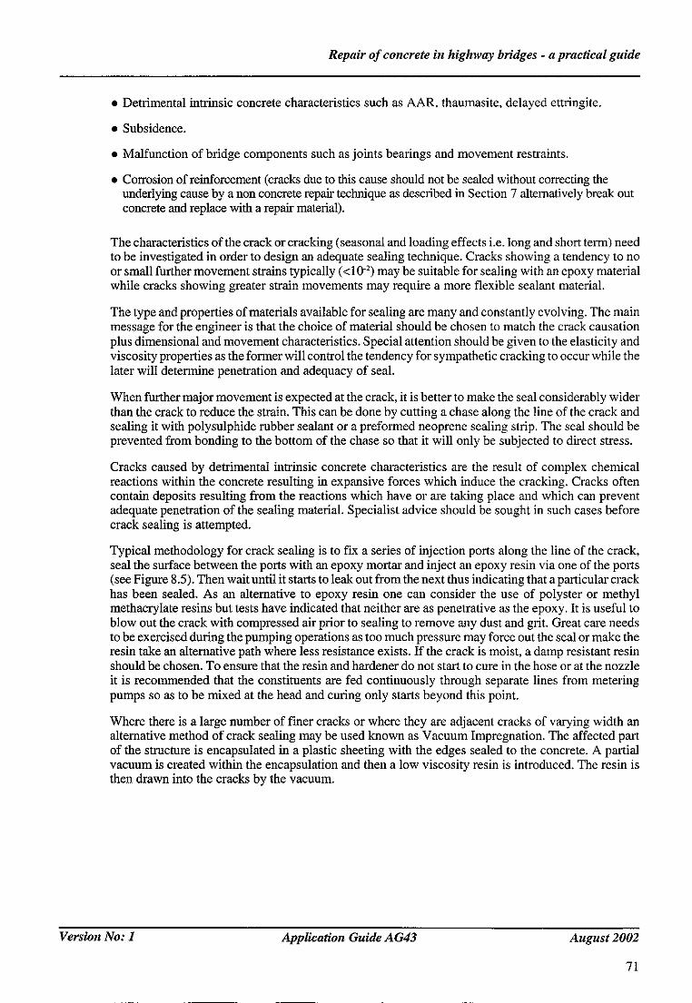
Repair o f concrete in highway bridges - a practical guide
• Detrimental intrinsic concrete characteristics such as AAR, thaumasite, delayed ettringite.
• Subsidence.
• Malfunction of bridge components such as joints beatings and movement restraints.
• Corrosion of reinforcement (cracks due to this cause should not be sealed without correcting the underlying cause by a non concrete repair technique as described in Section 7 alternatively break out concrete and replace with a repair material).
The characteristics of the crack or cracking (seasonal and loading effects i.e. long and short term) need to be investigated in order to design an adequate sealing technique. Cracks showing a tendency to no or small further movement strains typically (<10 -2 ) may be suitable for sealing with an epoxy material while cracks showing greater strain movements may require a more flexible sealant material.
The type and properties of materials available for sealing are many and constantly evolving. The main message for the engineer is that the choice of material should be chosen to match the crack causation plus dimensional and movement characteristics. Special attention should be given to the elasticity and viscosity properties as the former wilI control the tendency for sympathetic cracking to occur while the later will determine penetration and adequacy of seal.
When further major movement is expected at the crack, it is better to make the seal considerably wider than the crack to reduce the strain. This can be done by cutting a chase along the line of the crack and sealing it with polysulphide rubber sealant or a preformed neoprene sealing strip. The seal should be prevented from bonding to the bottom of the chase so that it will only be subjected to direct stress.
Cracks caused by detrimental intrinsic concrete characteristics are the result of complex chemical reactions within the concrete resulting in expansive forces which induce the cracking. Cracks often contain deposits resulting from the reactions which have or are taking place and which can prevent adequate penetration of the sealing material. Specialist advice should be sought in such cases before crack sealing is attempted.
Typical methodology for crack sealing is to fix a series of injection ports along the line of the crack, seal the surface between the ports with an epoxy mortar and inject an epoxy resin via one of the ports (see Figure 8.5). Then wait until it starts to leak out from the next thus indicating that a particular crack has been sealed. As an alternative to epoxy resin one can consider the use of polyster or methyl methacrylate resins but tests have indicated that neither are as penetrative as the epoxy. It is useful to blow out the crack with compressed air prior to sealing to remove any dust and grit. Great care needs to be exercised during the pumping operations as too much pressure may force out the seal or make the resin take an alternative path where less resistance exists, ff the crack is moist, a damp resistant resin should be chosen. To ensure that the resin and hardener do not start to cure in the hose or at the nozzle it is recommended that the constituents are fed continuously through separate lines from metering pumps so as to be mixed at the head and curing only starts beyond this point.
Where there is a large number of finer cracks or where they are adjacent cracks of varying width an alternative method of crack sealing may be used known as Vacuum Impregnation. The affected part of the structure is encapsulated in a plastic sheeting with the edges sealed to the concrete. A partial vacuum is created within the encapsulation and then a low viscosity resin is introduced. The resin is then drawn into the cracks by the vacuum.
Version No: 1 Application Guide AG43 August 2002
71

Repair o f concrete in highway bridges - a practical guide
Figure 8.5 Crack sealing in concrete beam using injection ports
8.9 Design and specification
Balance of opinion is that specification should not name products. BBA Certification (or similar) appears to be preferred by most specifiers. In general existing specifications using proprietary products have worked where every aspect of the process has been carefully monitored and specifications/ instructions fully complied with.
For extensive projects with large budgets or and/or lasting many years it will be appropriate for the project team to consider amending or developing standard specifications to suit their own requirements. Trials to establish suitability of proposed materials/application methods are a prerequisite for confidence in the end result and should be considered for all but the smallest repair projects. The project team must assess the proportion of trial costs which would be reasonable against the overall project budget and the cost of remedial works which could be required beyond the contractual maintenance period or as a possible result of accepting proposals which subsequently prove ineffective. For example, most repair contracts effected under ICE 5 'h the onus is on the Contractor to comply with the Contract - not the material supplier.
Any 'guarantees' mentioned by any other party (however well meaning) must be regarded as contractually irrelevant unless the standard Conditions of Contract are amended accordingly. In this regard specialist advice on contract law may be worth seeking. It should be appreciated that any course of action that extends a contractor's obligations is likely to impose an additional cost that may result in higher rates.
It is very easy to amend contract clauses and specifications in a way that appear to give the employer confidence that the Contractor will be responsible for all or any remedial works, and associated costs, for years to come. It is rather more difficult to make them stick many years down the line.
Version No: 1 Application Guide A G43 August 2002
72
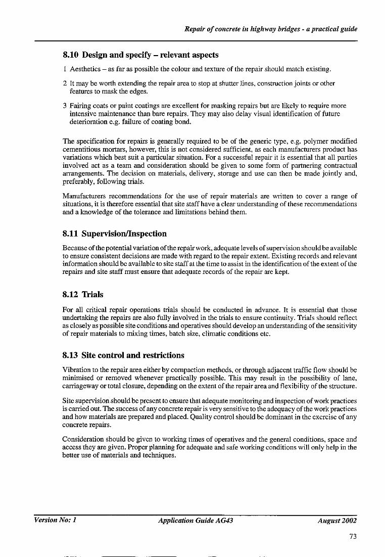
Repair o f concrete in highway bridges - a practical guide
8.10 Design and specify - relevant aspects
1 Aesthetics - as far as possible the colour and texture of the repair should match existing.
2 It may be worth extending the repair area to stop at shutter lines, construction joints or other features to mask the edges.
3 Fairing coats or paint coatings are excellent for masking repairs but are likely to require more intensive maintenance than bare repairs. They may also delay visual identification of future deterioration e.g. failure of coating bond.
The specification for repairs is generally required to be of the generic type, e.g. polymer modified cementitious mortars, however, this is not considered sufficient, as each manufacturers product has variations which best suit a particular situation. For a successful repair it is essential that all parties involved act as a team and consideration should be given to some form of partnering contractual arrangements. The decision on materials, delivery, storage and use can then be made jointly and, preferably, following trials.
Manufacturers recommendations for the use of repair materials are written to cover a range of situations, it is therefore essential that site staff have a clear understanding of these recommendations and a knowledge of the tolerance and limitations behind them.
8.11 Supervision/Inspection
Because of the potential variation of the repair work, adequate levels of supervision should be available to ensure consistent decisions are made with regard to the repair extent. Existing records and relevant information should be available to site staff at the time to assist in the identification of the extent of the repairs and site staff must ensure that adequate records of the repair are kept.
8.12 Trials
For all critical repair operations trials should be conducted in advance. It is essential that those undertaking the repairs are also fully involved in the trials to ensure continuity. Trials should reflect as closely as possible site conditions and operatives should develop an understanding of the sensitivity of repair materials to mixing times, batch size, climatic conditions etc.
8.13 Site control and restrictions
Vibration to the repair area either by compaction methods, or through adjacent traffic flow should be minimised or removed whenever practically possible. This may result in the possibility of lane, carriageway or total closure, depending on the extent of the repair area and flexibility of the structure.
Site supervision should be present to ensure that adequate monitoring and inspection of work practices is carried out. The success of any concrete repair is very sensitive to the adequacy of the work practices and how materials are prepared and placed. Quality control should be dominant in the exercise of any concrete repairs.
Consideration should be given to working times of operatives and the general conditions, space and access they are given. Proper planning for adequate and safe working conditions will only help in the better use of materials and techniques.
Version No: 1 Application Guide A G43 August 2002
73

Repair o f concrete in highway bridges - a practical guide
Due care and attention needs to be given to environmental needs during any concrete repair:
(a) The need to minimise pollution and to have adequate protective and contingency measures is important, particularly over rivers where the Envh'onment Agency will require approval and method statements for working procedures.
(b) Countryside and wildlife will need to be adequately thought about and protected - more so in areas of SSSI/AONB and local trusts.
(c) Protected species of flora and fauna etc might occasionally alter the methods of working. Where large sites are being carried out, some form of Environmental Impact Assessment may be required.
8.14 Installation
There are many aspects during installation of the concrete repair that may be critical:
(a) Removal of adequate area of existing concrete (covered in durability), and proper preparation of existing steel and concrete surfaces.
(b) Structural continuity to be safely maintained while the repairs are being carried out. Depending on the extent and location within the structure this may require temporary propping/additional strengthening or reduction in live loading. Proper structural investigation should be carried out where the structure is continued to be used whilst the repair work is undertaken.
(c) Utilising specialist repair advice on difficult repair areas, i.e. post tensioned or prestressed concrete.
(d) Secondary reinforcing for large areas. This will need to be considered job for job and wilt require structural engineering advice.
Repair work to be carried out by approved contractor using approved materials and methods as discussed earlier in this section. It must be emphasised that the management constraints will be different for every structure. All the management issues including traffic, environmental, health and safety etc (see Section 6) should given be proper consideration prior to installation of repair.
8.15 Strength and propping
The repair may involve the removal of material, which contributes directly to the strength of the structure. The extent to which strength of the structure will be affected by removal of such material must be defined and any necessary limits set. This will include consideration of stress transfer and any necessary temporary support. Additionally the extent of repair that may be undertaken in one phase may need controlling. It is essential that the site team fully understand the situation.
8.16 Contractual arrangements
To obtain competitive tenders for concrete repair is problematic. Most forms of contract perform best with predictability of outcome. The inevitable variation that will occur in repair contracts can be accommodated by the use of provisional quantities, but where access is difficult and time limited additional items will be necessary to cover for further site visits.
Version No: 1 Application Guide AG43 August 2002
74
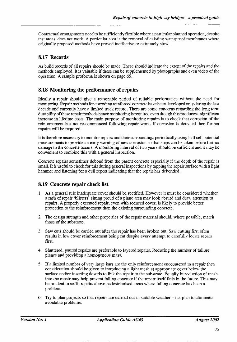
Repair o f concrete in highway bridges - a practical guide
Contractual arrangements need to be sufficiently flexible where a particular planned operation, despite test areas, does not work. A particular area is the removal of existing waterproof membranes where originally proposed methods have proved ineffective or extremely slow.
8.17 Records
As build records of all repairs should be made. These should indicate the extent of the repairs and the methods employed. It is valuable if these can be supplemented by photographs and even video of the operation. A sample proforma is shown on page 65.
8.18 Monitoring the performance of repairs
Ideally a repair should give a reasonable period of reliable performance without the need for monitoring. Repair methods for corroding reinforced concrete have been developed only during the last decade and currently have a limited track record. There are some concerns regarding the long term durability of these repair methods hence monitoring is required even though this produces a significant increase in lifetime costs. The main purpose of monitoring repairs is to check that corrosion of the reinforcement has not re-commenced following repair work. If corrosion is detected then further repairs will be required.
It is therefore necessary to monitor repairs and their surroundings periodically using half cell potential measurements to provide an early warning of new corrosion so that steps can be taken before further damage to the concrete occurs. A monitoring interval of two years should be sufficient and it may be convenient to combine this with a general inspection.
Concrete repairs sometimes debond from the parent concrete especially if the depth of the repair is small. It is useful to check for this during general inspections by tapping the repair surface with a light hammer and listening for a dull report indicating that the repair has debonded.
8.19 Concrete repair check list
As a general rule inadequate cover should be rectified. However it must be considered whether a rash of repair 'blisters' sitting proud of a plane area may look absurd and draw attention to repairs. A properly executed repair, even with reduced cover, is likely to provide better protection to the reinforcement than the existing surrounding concrete.
2 The design strength and other properties of the repair material should, where possible, match those of the substrate.
Saw cuts should be carded out after the repair has been broken out. Saw cutting first often results in low cover reinforcement being cut despite every attempt to carefully locate rebars first.
4 Shuttered, poured repairs are preferable to layered repairs. Reducing the number of failure planes and providing a homogenous mass.
If a limited number of very large bars are the only reinforcement encountered in a repair then consideration should be given to introducing a light mesh at appropriate cover below the surface and/or inserting dowels to link the repair to the substrate. Equally introduction of mesh into the repair may help prevent falling concrete if the repair itself fails in the future. This may be prudent in soffit repairs above pedestrianised areas where failing concrete has been a problem.
6 Try to plan projects so that repairs are carded out in suitable weather - i.e. plan to eliminate avoidable problems.
Version No: 1 Application Guide AG43 August 2002
75

Repair o f concrete in highway bridges - a practical guide
If repair is required due to water penetration look at ways of preventing water reaching the repair e.g. introducing drip checks, drip notches, locally varying the thickness of the repaired areas to shed, rather than attract, water.
8 Be aware that when the worst areas of a structure are repaired then secondary deterioration will stand out and the overall effect may not be of significant improvement.
9 Where cracks exist in the substrate they may well appear in time in the repair. The introduction of crack inducers may encourage them to appear where the designer can deal with them.
i0 Try to avoid replacing a bad detail with the same bad detail e.g. if a repair is required because the original designer omitted a water bar at a construction joint then consider the possibility of rectifying this omission.
11 The ideal repair material for deck repairs may not be suitable for walls and soffits as well. Be prepared to consider different solutions for different parts of the same structure.
12 The use of fibres (steel and synthetic) can be very beneficial in minimising cracking.
13 Repair materials with relatively low strength, low shrinkage, high creep and low modulus of elasticity are most desirable for non-stmcturai protective repairs.
14 Consideration should be given to specifying compatibility, low shrinkage and low permeability.
15 If reinforcement is being jet or blast cleaned it makes sense to clean any replacement reinforcement when fixed.
16 If it is at all likely that future cathodic protection will be installed then specification of component parts of the repair must take this into account.
17 Leaking construction joints are a common cause for concrete repair. Introducing sealants into chases cut in the repaired concrete can prevent recurrence.
18 Shrinkage can be reduced by using 30% by weight of aggregate in repair materials.
19 Strength and other properties of the repair material should be measured using the same tests that were used to determine the properties of the substrate concrete. Proprietary systems may select the tests that show their properties in the best light. When assessing systems check which tests were used.
20 There is no substitute for experience. When assessing a concrete repair system take up references where the structure and conditions are similar to the one being repaired.
21 Optimum stiffness for a repair material is 30% greater than the substrate.
22 Repair failures generally seem to result from a combination of factors conspiring against success rather than single omissions or reasons. It cannot be over emphasised that every aspect of a repair should be strictly controlled and in accordance with specifications and manufacturer's requirements if a successful outcome is to be achieved.
23 There should be no free surface moisture when the repair is applied i.e. that would wet a hand drawn across the surface. With proprietary systems which include a bonding agent (usually polymer modified) no pre-wetting is required. When using Portland cement based repair materials it is preferable to err on the side of surfaces being too dry rather than too wet.
24 The temperature of the substrate can also affect bond strength. With Portland cement based materials optimum bond is achieved at around 20°C. The temperature less than 10°C may reduce bond strength.
Version No: 1
76
Application Guide AG43 August 2002
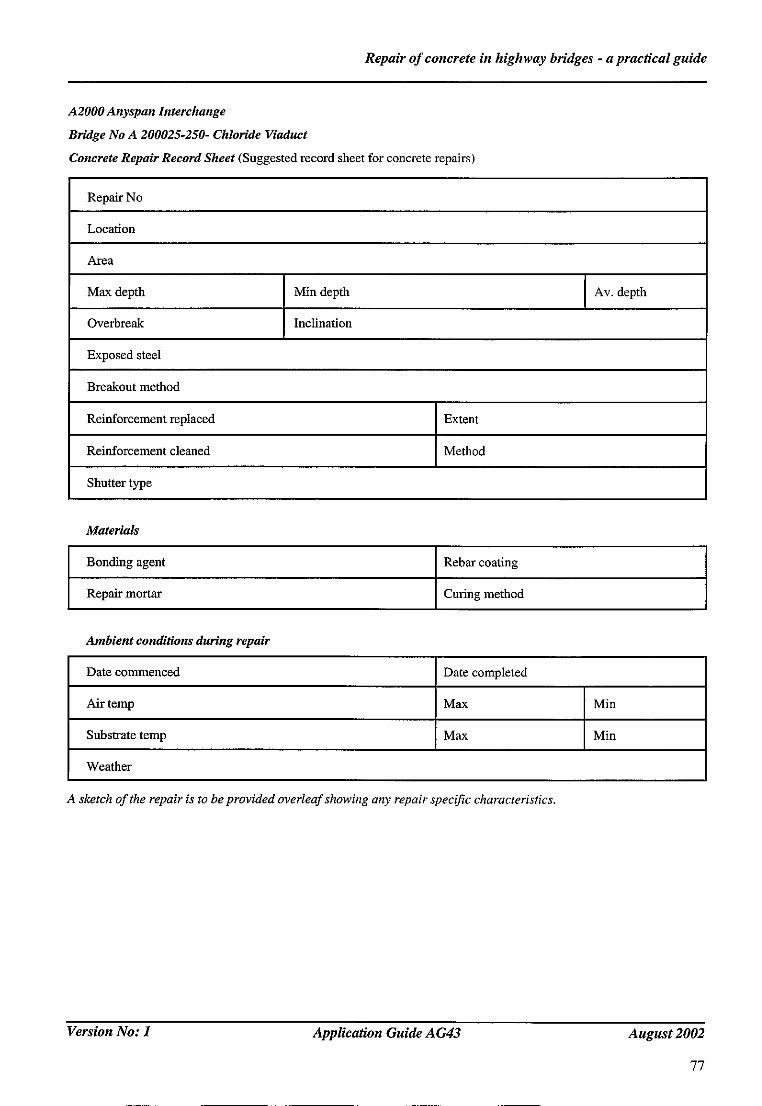
Repair o f concrete in highway bridges - a practical guide
A2000 Anyspan Interchange
Bridge No A 200025-250- Chloride Viaduct
Concrete Repair Record Sheet (Suggested record sheet for concrete repairs)
Repair No
Location
Area
Max depth Min depth Av. depth
Overbreak Inclination
Exposed steel
Breakout method
Reinforcement replaced Extent
Reinforcement cleaned Method
Shutter type
Materials
Bonding agent Rebar coating
Repair mortar Curing method
Ambient conditions during repair
Date commenced Date completed
Air temp Max Min
Substrate temp Max Min
Weather
A sketch of the repair is to be provided overleaf showing any repair specific characteristics.
Version No: 1 Application Guide AG43 August 2002
77

Repair o f concrete in highway bridges - a practical guide
9 ACKNOWLEDGEMENTS
This report was prepared by members of the CSS/HA/TRL Concrete Bridge repah" Working Group under the guidance of S Pearson.
The project was jointly sponsored by the Highways Agency (Project officer N Loudon) and the CSS Working Party on Highway Research (Chairman R Wilkins)). Their support is gratefully acknowledged.
Many local authority Bridge Engineers contributed to the project by hosting visits, taking part in discussions and answering questions. The Working Group is grateful to all those who gave freely of their time and expertise.
Version No: 1 Application Guide AG43 August 2002
79
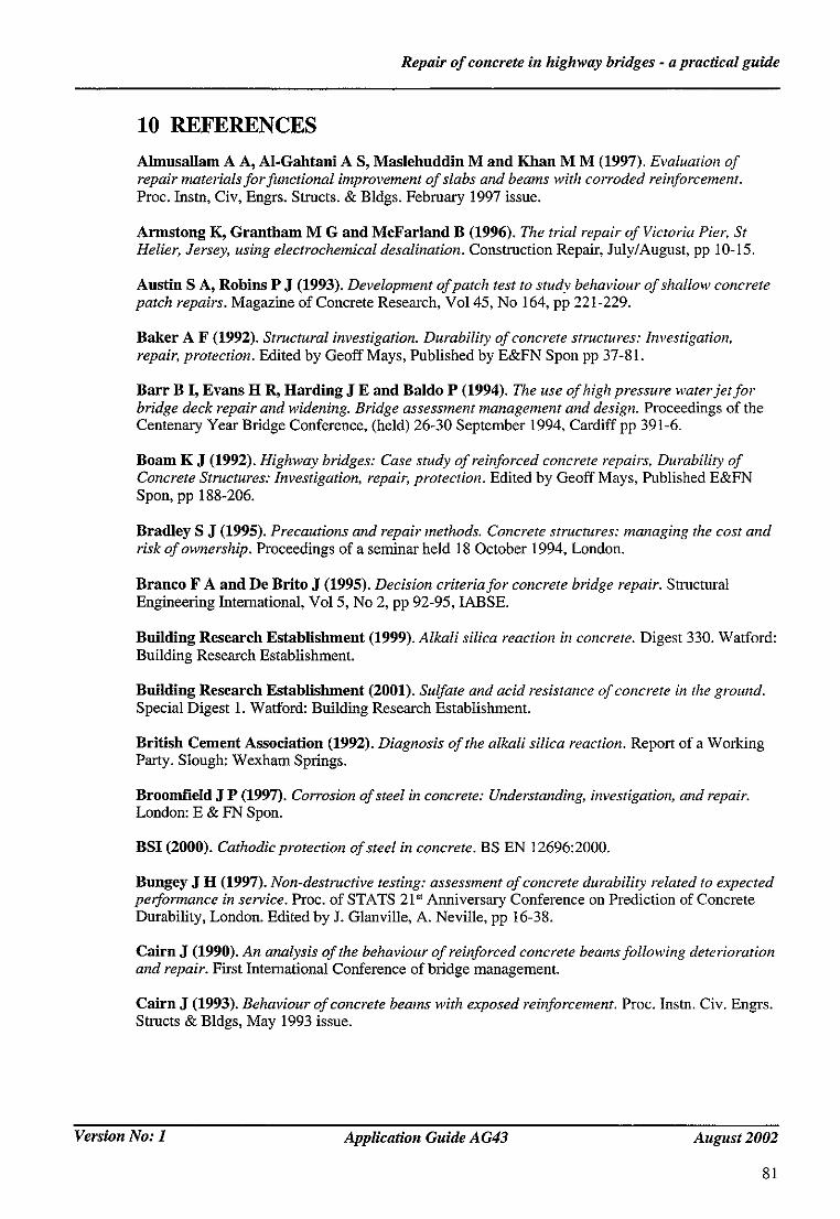
Repair of concrete in highway bridges - a practical guide
10 REFERENCES
Almnsallam A A, A1-Gahtaui A S, Maslehuddin M and Khan M M (1997). Evaluation of repair materials for functional improvement of slabs and beams with corroded reinforcement. Proc. Instn, Civ, Engrs. Structs. & Bldgs. February 1997 issue.
Armstong K, Grantham M G and McFarland B (1996). The trial repair of Victoria Pier, St Helier, Jersey, using electrochemical desalination. Construction Repair, July/August, pp i0-15.
Austin S A, Robins P J (1993). Development of patch test to study behaviour of shallow concrete patch repairs. Magazine of Concrete Research, Vo145, No 164, pp 221-229.
Baker A F (1992). Structural investigation. Durability of concrete structures: Investigation, repair, protection. Edited by Geoff Mays, Published by E&FN Spon pp 37-81.
Barr B I, Evans H R, Harding J E and Baldo P (1994). The use of high pressure water jet for bridge deck repair and widening. Bridge assessment management and design. Proceedings of the Centenary Year Bridge Conference, (held) 26-30 September 1994, Cardiff pp 391-6.
Boam K J (1992). Highway bridges: Case study of reinforced concrete repairs, Durability of Concrete Structures: Investigation, repair, protection. Edited by Geoff Mays, Published E&FN Spon, pp 188-206.
Bradley S J (1995). Precautions and repair methods. Concrete structures: managing the cost and risk of ownership. Proceedings of a seminar held 18 October 1994, London.
Branco F A and De Brito J (1995). Decision criteria for concrete bridge repair. Structural Engineering International, Vol 5, No 2, pp 92-95, IABSE.
Building Research Establishment (1999). Alkali silica reaction in concrete. Digest 330. Watford: Building Research Establishment.
Building Research Establishment (2001). Sulfate and acid resistance of concrete in the ground. Special Digest 1. Wafford: Building Research Establishment.
British Cement Association (1992). Diagnosis of the alkali silica reaction. Report of a Working Party. Slough: Wexham Springs.
Broomfield J P (1997). Corrosion of steel in concrete: Understanding, investigation, and repair. London: E & FN Spon.
BSI (2000). Cathodic protection of steel in concrete. BS EN 12696:2000.
Bungey J H (1997). Non-destructive testing: assessment of concrete durability related to expected performance in service. Proc. of STATS 21 st Anniversary Conference on Prediction of Concrete Durability, London. Edited by 1. Glanville, A. Neville, pp 16-38.
Cairn J (1990). An analysis of the behaviour of reinforced concrete beams following deterioration and repair. First International Conference of bridge management.
Cairn J (1993). Behaviour of concrete beams with exposed reinforcement. Proc. Instn. Civ. Engrs. Structs & Bldgs, May 1993 issue.
Version No: 1 Application Guide AG43 August 2002
81

Repair o f concrete in highway bridges - a practical guide
Cairns J (1993). Load relief during structural repairs to reinforced concrete beams. Proc. Instn. Civ. Engrs, Stmcts. & Bldgs., November 1993 issue.
Cairns J (1995). Load relief during structural repairs to reinforced concrete beams (discussion). Proc. Instn. Civ. Engrs. Structs. & Bldgs., February issue.
Cairns J and Zhao Z. (1993). Behaviour of concrete beams with exposed reinforcement. Proc. Insm. Civ. Engrs. Structs. & Bldgs., May 1993 issue.
Calder A J J and Chowdhury Z S (1996). Fourth Int. Conf. on Corrosion of reinforcement in Concrete Construction, Cambridge.
Chess P M (1998). Cathodic protection of steel in concrete. London: E & FN Spon.
Cieland D L, Yeoh K M and Long A E (1997). Corrosion of reinforcement in concrete repair. Construction and Building Materials, Vol 11, No 4, pp 233-238.
Concrete Bridge Development Group (2002). Guide to testing and monitoring the durability of concrete structures. Technical Guide No 2.
The Concrete Society (1988). Cathodic protection of reinforced concrete. Technical Report N0.36.
The Concrete Society (1991). Patch repair of reinforced concrete - subject to reinforcement corrosion. Model specification and method of measurement. Technical Report No. 38.
The Concrete Society (1992). Non-structural cracks in concrete. Technical Report No. 22.
The Concrete Society (1995). Alkali silica reaction: Minimising the r&k to concrete. Guidance notes and model specification. Technical Report TR30.
The Concrete Society (2000). Diagnosis of deteriorution in concrete structures. Technical Report No. 54.
The Concrete Society (2000). Design guidance for strengthening concrete structures using fibre composite materials. Technical Report No. 55.
Cronin D J and Kay W (1992). Repair methods in practise. Proc. of Int. Rilem Conf. on Rehabilitation of Concrete Structures, Melbourne, Australia 31 Aug-2 Sep, pp 385-402.
Doolan T F (1992). Repair strutegiesfor concrete bridges. Proc. of Int. Rilem Conf. on Rehabilitation of Concrete Structures, Melbourne, Australia, 31 Aug-2 Sep, pp 61-69.
Emberson N K and Mays G C (1996). Significance of property mismatch in the patch repair of structural concrete. Part 3: Reinforced concrete members in fiexure. Magazine of Concrete Research, Vo148, No 174, pp 45-57.
Emberson N K and Mays G G (1990). Significance of property mismatch in the patch repair of structural concrete Part 1: Properties of repair systems. Magazine of Concrete Research, 42, No. 152, pp 147-160.
Emmons P H and Vaysburd A M (1994). Factors affecting the durability of concrete repairs: the contractor's viewpoint. Construction and Building Materials, Vol 8, No 1, pp 5-16.
Emmons P H and Vaysburd A M (1996). System concept in design and construction of durable concrete repairs. Construction and Building Materials, Vol 10, No 1, pp 69-75.
V e r s i o n N o : 1 Application Guide AG43 August 2002
82
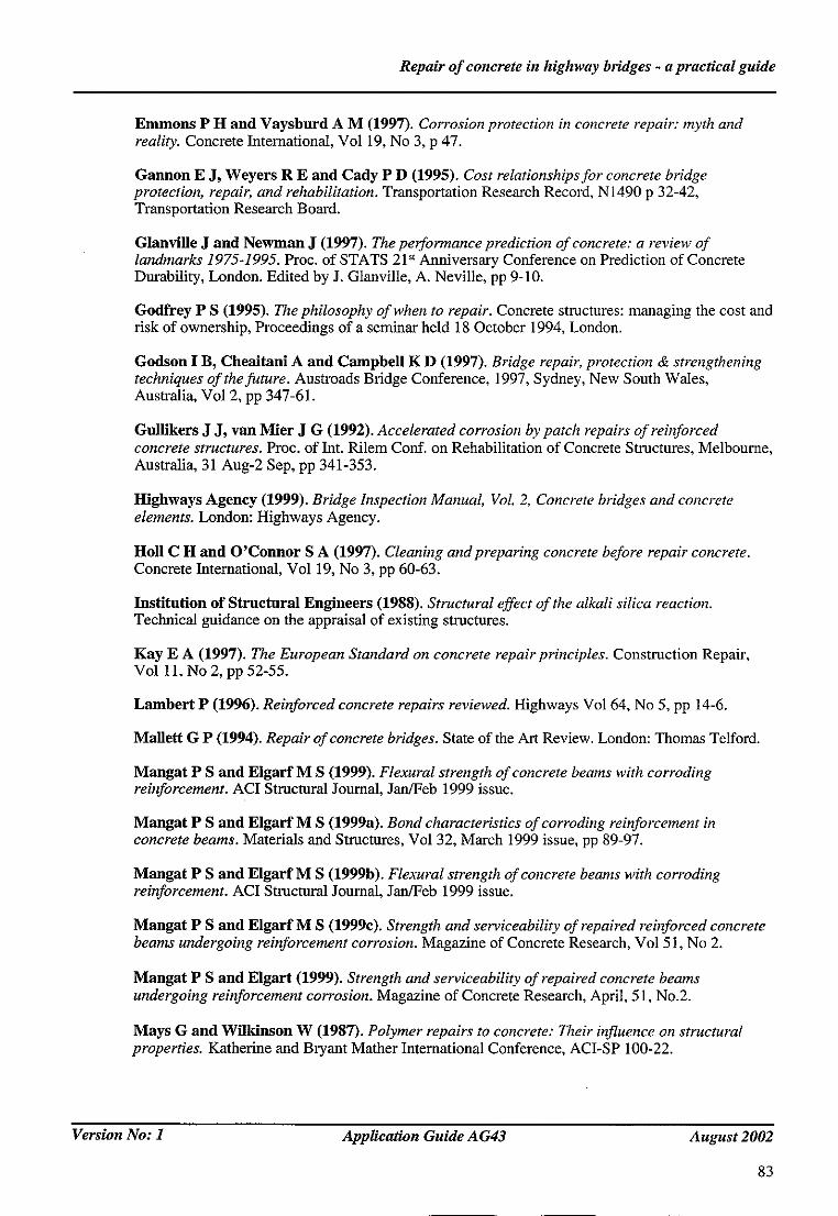
Repair of concrete in highway bridges - a practical guide
Emmons P H and Vaysburd A M (1997). Corrosion protection in concrete repair: myth and reality. Concrete International, Vol 19, No 3, p 47.
Gannon E J, Weyers R E and Cady P D (1995). Cost relationships for concrete bridge protection, repair, and rehabilitation. Transportation Research Record, N1490 p 32-42, Transportation Research Board.
Glanville J and Newman J (1997). The performance prediction of concrete: a review of landmarks 1975-1995. Proc. of STATS 21 st Anniversary Conference on Prediction of Concrete Durability, London. Edited by J. G1anville, A. Neville, pp 9-10.
Godfrey P S (1995). The philosophy of when to repair. Concrete structures: managing the cost and risk of ownership, Proceedings of a seminar held 18 October 1994, London.
Godson I B, Cheaitani A and Campbell K D (1997). Bridge repair, protection & strengthening techniques of the future. Austroads Bridge Conference, 1997, Sydney, New South Wales, Australia, Vol 2, pp 347-61.
Gullikers J J, van Mier J G (1992). Accelerated corrosion by patch repairs of reinforced concrete structures. Proc. of Int. Rilem Conf. on Rehabilitation of Concrete Structures, Melbourne, Australia, 31 Aug-2 Sep, pp 341-353.
Highways Agency (1999). Bridge Inspection Manual, VoL 2, Concrete bridges and concrete elements. London: Highways Agency.
t tol l C H and O'Connor S A (1997). Cleaning and preparing concrete before repair concrete. Concrete International, Vol 19, No 3, pp 60-63.
Institution of Structural Engineers (1988). Structural effect of the alkali silica reaction. Technical guidance on the appraisal of existing structures.
Kay E A (1997). The European Standard on concrete repair principles. Construction Repair, Vol 11, No 2, pp 52-55.
Lambert P (1996). Reinforced concrete repairs reviewed. Highways Vol 64, No 5, pp 14-6.
Mallett G P (1994). Repair of concrete bridges. State of the Art Review. London: Thomas Telford.
Mangat P S and Elgarf M S (1999). Flexural strength of concrete beams with corroding reinforcement. ACI Structural Journal, Jan/Feb 1999 issue.
Mangat P S and Elgarf M S (1999a). Bond characteristics of corroding reinforcement in concrete beams. Materials and Structures, Vol 32, March 1999 issue, pp 89-97.
Mangat P S and Elgarf M S (1999b). Flexural strength of concrete beams with corroding reinforcement. ACI Structural Journal, Jan/Feb 1999 issue.
Mangat P S and Elgarf M S (1999c). Strength and serviceability of repaired reinforced concrete beams undergoing reinforcement corrosion. Magazine of Concrete Research, Vol 5 I, No 2.
Mangat P S and Elgart (1999). Strength and serviceability of repaired concrete beams undergoing reinforcement corrosion. Magazine of Concrete Research, April, 51, No.2.
Mays G and Wilkinson W (1987). Polymer repairs to concrete: Their influence on structural properties. Katherine and Bryant Mather International Conference, ACI-SP 100-22.
Version No: 1 Application Guide A G43 August 2002
83

Repair o f concrete in highway bridges - a practical guide
Mays G C and Barnes R A (1995). The structural effectiveness of large volume patch repairs to concrete structures. Proc. Insm, Civ, Engrs. Structs. & Bldgs. November issue.
Mietz J (1998). Electrochemical rehabilitation methods for reinforced concrete structures - a state of the art report. European Federation of Corrosion Publications Number 24. London: IOM Communications Ltd.
Morgan D R (1996). Compatibility of concrete repair material and systems. Construction and Building Materials, Vol 10, No 1, pp 57-67.
Patel R G (1992). Research onflowable concrete. Research Report RR322. Crowthome: TRL limited.
Patel R G and MeKenzle M (2000). Electrochemical treatment to reinforced concrete. Project Report PR/IS/10/00. Crowthome: TRL Limited. (Unpublished report available on direct personal application only)
Pearson S and Cuninghame J (1998). Water management for durable bridges. Application Guide AG33. Crowthorne: TRL Limited.
Pocock D C (1996). Societies, standards, and working parties-the present position in European standards for cathodic protection of concrete structures. Construction and Building Materials, Vol 10, No 1, pp 101-107.
Powers T C (1956). Resistance to weathering -freezing and thawing. ASTM Special Technical Publication, No. 169, pp 182-7
Purvis R L (1994). Underwater bridge maintenance and repair, NCHRP synthesis of highway practice. Transportation Research Board.
Read G E (1992). Degradation of reinforced concrete structures due to corrosion attack. International Conference on Structural Improvement Through Corrosion Protection of Reinforced Concrete. Institute of Corrosion, London, Conference Document E7190.
Rigden S R, Burley E and Tajalli A (1995). The assessment of future repair and maintenance costs of bridges in net present value terms. Proceedings from one-day seminar on whole life costing - concrete bridges, Concrete bridge development group, BCA, Crowthome, pp 15-26.
Rostam S (1996). High performance concrete cover-why it is needed, and how to achieve it in practice. Construction and Building Materials, Vol 10, No 5, pp 407-421.
Sergi G and Page C L (1999). Sacrificial anodes for cathodic protection of reinforcing steel around patch repairs applied to chloride contaminated concrete. Proceedings of Eurocorr 99, Aachan.
Shahrooz B M, Miller R A, Saraf V K and Godbole B (1994). Behaviour of reinforced concrete slab bridges during and after repair. Transportation Research Record, Transportation Research Board, No. 1442, pp 128-35.
Somerville G (1997). Engineering design and service life: a framework for the future. Proc. of STATS 21 ~' Anniversary Conference on Prediction of Concrete Durability, London. Edited by J. Glanville, A. Neville. pp 59-74.
Tabor L J (1978). The evaluation of resin systems for concrete repair. Magazine of Concrete Research, 1978, 30, No.105
Tabor L J (1992). Repair materials and techniques. Durability of concrete structures: Investigation, repair, protection. Edited by Geoff Mays, Published by E&FN Spon, pp 82-127.
Version No: 1 Application Guide A G43 August 2002
84

Repair o f concrete in highway bridges - a practical guide
Technical Liaison Committee (2000). Half-cell potential surveys of reinforced concrete structures. Current Practice Guide Sheet No 120, Report by Technical Liaison Committee of the Institute of Corrosion and the Concrete Society, JuIy-August, pp 43-45.
Thaumasite Expert Group (1999). The thaumasite form of sulfate attack: Risks, diagnosis, remedial works and guidance on new construction.
Vassie P R (1984). Reinforcement corrosion and the durability o f concrete bridges. Proceedings of the Institution of Civil Engineers, Part 1, 76, pp 713-723.
Vassie P R (1991). The half-cell potential method for locating corroding reinforcement in concrete structures. Crowthome: TRL Limited.
Wallbank E J (1989). The performance of concrete in bridges: a survey of 200 highway bridges. London: The Stationery Office.
Wyatt R A and Oehlers D J (1992). Application of composite plated beam construction to existing railway bridge corbels. Proc. of Int. Rilem Conf. on Rehabilitation of Concrete Structures, Melbourne, Australia, 31 Aug-2 Sep, pp 297-308.
Wynhoven J H, Cox J P, Goad A C and Hunton D A (1992). Rehabilitation revbited. Proc. of Int. Rilem Conf. on Rehabilitation of Concrete Structures, Melbourne, Australia 31 Aug-2 Sep, pp 377-384.
Version No: 1 Application Guide AG43 August 2002
85
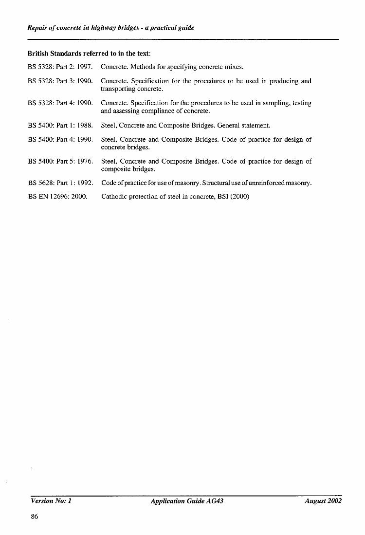
Repair o f concrete in highway bridges - a practical guide
British Standards referred to in the text:
BS 5328: Part 2: 1997. Concrete. Methods for specifying concrete mixes.
BS 5328: Part 3: 1990. Concrete. Specification for the procedures to be used in producing and transporting concrete.
BS 5328: Part 4: 1990. Concrete. Specification for the procedures to be used in sampling, testing and assessing compliance of concrete.
BS 5400: Part 1: 1988. Steel, Concrete and Composite Bridges. General statement.
BS 5400: Part 4: 1990. Steel, Concrete and Composite Bridges. Code of practice for design of concrete bridges.
BS 5400: Part 5: 1976. Steel, Concrete and Composite Bridges. Code of practice for design of composite bridges.
BS 5628: Part 1: 1992. Codeofpracticeforuseofmasonry.Stlucturaluseofunreinforcedmasomy.
BS EN 12696: 2000. Cathodic protection of steel in concrete, BSI (2000)
Version No: 1
86
Application Guide AG43 August 2002

Repair o f concrete in highway bridges - a practical guide
References for Glossary:
Barke r J A (1983). Dictionary of concrete. Harlow: Construction Press.
B a r k e r J A (1981). Dictionary of soil mechanics and foundation engineering. Harlow: Construction Press.
BS 6918:1990. Glossary of Terms for corrosion of metals and alloys. London: British Standard Institute.
BSI (1993). Glossary o f building and civil engineering terms. Blackwell Scientific Publications.
Emerson M (1995). Mechanisms o f water absorption by concrete. Proceedings of International conference on Protection of Concrete, University of Dundee, September 1995. Published by E & F N Sport, London. (Ed. R K Dh'lr and J W Green).
Hall C (1981). Water movement in porous buiiding materials - IV. Building and environment. 1981. Vol 16. No 3, pp 201 - 207.
Scott J S (1991). Dictionary of Civil Engineering. London: Penguin Books.
Stewart Stein J (1980). Construction glossary. USA: John Wiley and Sons.
Whiteoak D (1990). Shell Bitumen Handbook. United Kingdom: Shell Bitumen.
Version No: 1 Application Guide AG43 August 2002
87

Repair of concrete in highway bridges - a practical guide
11 GLOSSARY
Alkali Silica Reaction (ASR):
British Board of Agrdment (BBA ):
Carbonation:
Cathodic protection ( CP):
Concrete scaling:
Corrosion:
Corrosion inhibitor:
Design manual for roads and bridges (DMRB):
Ettringite:
General corrosion:
Hydrogen embrittlement:
Half ceil potential:
Laitance:
Macrocell:
A chemical reaction of sodium and potassium ions in Portland cement with reactive silica aggregate. This reaction generates expansive forces in hardened concrete which can cause cracking.
Organisation which tests materials and products to confirm the requirements of the specifications, then issues a Roads and Bridges certificate for those products which are suitable for use on highways (as opposed to the general certificate which is intended for buildings).
A chemical combination between the carbon dioxide in the air and the lime in the concrete, reducing the pH so that steel may rest, and also causing drying sluinkage.
It is electrochemical technique to stop corrosion of steel in chloride contaminated concrete or to prevent corrosion in case of future chloride contamination.
Local flaking or peeling away of the surface of the concrete.
Physiochemical interaction between a metal and its environment which results in impairment of the function of the metal.
Chemical substance which decreases the corrosion rate when present or placed in concrete at a suitable concentration.
Contains design standards (BDs) and advice notes (BAs). Issued by the Highways Agency.
A product of sulfate attack on concrete, which causes the concrete to expand and subsequently crack.
A corrosion process where steel in concrete rusts uniformly over its surface usually because the alkalinity of the concrete has been reduced by carbonation.
A process resulting in a decrease of the toughness or ductility of a metal due to absorption of hydrogen.
The difference in electrical potential between an electrode and the electrolyte solution with which it is in contact, measured with reference to another specified reference electrode.
A scum on a cement concrete surface which is weaker then the rest of the concrete and should be removed.
Corrosion cell where the anode and the cathode are discrete and separated by distance of more than 10mm.
Version No: 1 Application Guide AG43 August 2002
89
Repair of concrete in highway bridges - a practical guide
Microcell:
MCHW:
Outgassing:
Passivity:
Pinholing:
Pinmg corrosion:
pH:
Pulverised fuel ash (PFA):
Restivity (electrical):
Rust:
Silane:
U4 finish:
Corrosion cell where anode and cathode are not discrete are separated by microscopic distances.
Manual of Contract documents for Highway Works; issued by the Highways Agency and mandatory for Highways Agency structures. Includes:
Volume 1 SHW: Specifications for highway works.
Volume 2 NGSHW: Notes for Guidance on the Specification for Highway Works.
Release of gas from a material, eg from a concrete deck due to the effect of increasing ambient temperature on the air and moisture in the voids of the concrete.
Is the decrease in the rate of corrosion of a metal resulting from the formation of a thin protective film (often invisible) of metal corrosion products, usually oxide.
This is associated with liquid applied waterproofing systems. Air or water vapour rises through the coating, causing small blisters on the surface which sometimes burst to form pinholes with diameter ranging between 1 and 8ram. If these are not closed, they leave a permanent pathway for moisture to reach the concrete deck.
A process where the steel corrosion results in pits (cavities extending from the surface into the metal) rapidly at a number of points as a result of chloride contamination at a boundary between the steel the cement paste.
Logaritham of the reciprocal of the molar concentration of the hydrogen ion; a scale indicating the acidity of a solution.
Finely ground coal of which 99% is smaller than 0.25mm diameter. Used as a replacement for cement in concrete.
It is a measure of how easily corrosion current can flow as a result of the potential differences caused by corrosion.
Visible corrosion products consisting mainly of hydrated iron oxides.
A colourless impregnant sprayed onto concrete surfaces to prevent the passage of water.
A description of the type of finish required for the concrete deck before waterproofing. It is taken from the 'Specification for Highway Works' Volume 1, Series 1700, Clause i708.
Version No: 1 Application Guide AG43 August 2002
90

Repair o f concrete in highway bridges - a practical guide
APPENDIX: STANDARD AND ADVICE NOTE RELEVANT TO CONCRETE BRIDGE REPAIR
The following tables give a list of all the sections and clauses of the Highways Agency (HA) Design Manual for Roads and Bridges (DMRB) and the Manual of Contract Documents for Highway Works, Specification for Highway Works (SHW) which contain information relevant for concrete bridge repah'.
Document DMRB reference reference Title Date of issue
Section(s) of document relevant to concrete repair
BD 15/92 1.3.2 General Principles for the Dec 1992 Several. Design and Construction of Bridges.
Use of BS5400: part 1: 1988.
BD 16/82 1.3 Design of Composite Bridges. Nov1982 Several
Use of BS5400: Part 5: 1979. Dec 1987
Amendment No 1.
BD 21/01 3.4.3 The Assessment of Highway May 2001 Includes methods of Bridges and Strnctures. assessment, and inspection
for assessment.
BD 24/92 1.3.1 Design Of Concrete Bridges. Nov 1992 Several.
Use of BS 5400: Part 4: 1990.
BD 27/86 3.3 Materials for the repair of Nov 1986 Includes model concrete Highway Structure specifications for repair
materials and impregnation.
BD 31/87 2.2 Buried Concrete Box Type Jan 1988 Includes requirements for Smactures. drainage, waterproofing
and joints.
BD 35/99 2.4.1 Quality Assurance Scheme for Aug1999 Several. Paints and Similar Protective Coatings.
BD 36/92 1.2.1 Evaluation of Maintenance Aug. 1992 Several Costs in Comparing Alternative Designs
BD 43/90 2.4 Criteria and Materials for the April 1990 6.2 Impregnation of Concrete Highway Structures
Continued ....
Version No: 1 Application Guide AG43 August 2002
91

Repair o f concrete in highway bridges - a practical guide
Document DMRB Section(s) of document reference reference Title Date of issue relevant to concrete repair
BD 47/99 2.3.4 Waterproofing and Surfacing Aug 1999 Several, of Concrete Bridge Decks.
BD 57/01 1.3,7 Design for Durability. Aug 2001 Several.
BD 63/94 3.1.4 Inspection of Highway Oct 1994 Requirements for Structures. inspections which
supersedes BA 18.
BD 67/96 2.2.7 Enclosure of Bridges. Aug 1996 Additional method of protecting the steel of a bridge flora corrosion, while providing access for inspection and maintenance.
BA 16/97 3.4.4 The Assessment of Highway May 1997 Includes advice on Bridges and Structures. maintenance and repair.
BA 27/99 2.4.2 Quality Assurance Scheme for Aug 1999 Several. Paints and Similar Protective Coatings.
BA 28/92 1.2.2 Evaluation of Maintenance Costs Aug 1992 Several. in Comparing Alternative Designs for Highway Structures
BA 33/90 2.4 Impregnation of Concrete Apr 1990 Several. Highway Structures.
Addendum May 1990
BA 35/90 3.3 Inspection and Repair of Concrete Jun 1990 Several. Highway Bridges.
BA 38/93 3.4.5 Assessment of the Fatigue Life Oct 1993 Includes guidance on of Corroded or Damaged assessment of the remaining Reinforcing bars. fatigue life of corroded or
damaged reinforcement.
BA 39/93 3.4.6 Assessment of Reinforced Apt 1993 Includes consideration for Concrete Half-joints. corrosion of reinforcement.
BA 41/98 1.3.11 The Design and Appearance Feb 1998 Includes advice on inspection, of Bridges. maintenance and weathering
considerations.
BA 42/96 1.3.12 The Design of Integral Bridges. Nov 1996 Several.
BA 43/94 3.3.2 Strengthening, Repair and Dec 1994 Includes case studies of Monitoring of Post-tensioned bridges, some of which have Concrete Bridge Decks. problems associated with poor
water management.
Continued ....
Version No: 1 Application Guide AG43 August 2002
92

Repair o f concrete in highway bridges - a practical guide
Document DMRB Section(s) of document reference reference Title Date of issue relevant to concrete repair
BA 47/99 2.3.5 Waterproofing and Surfacing Aug 1999 Several. of Concrete Bridge Decks.
BA 44/96 3.4.15 Assessment of Concrete Highway Nov 1996 Several Bridges & Structures.
BA 52/94 3.4.10 The assessment of concrete Nov 1994 Several structures affected by alkali silica reaction
BA 50/93 3.1.3 Post-tensioned Concrete Bridges: InI i993 Includes advice on inspection Planning, Organisation and of post-tensioned concrete Methods for Carrying Out bridges. Special Inspections.
BA 51/95 3.4.13 The assessment of Concrete Feb 1995 Includes guidance for the Highway Structures Affected assessment of concrete by Steel Corrosion. structures affected by
reinforcement corrosion.
BA 57/01 1.3.7 Design for Durability. Aug 2001 Several.
BA 58/94 1.3.10 Design of Bridges and Concrete Nov 1994 Advice on corrosion structures with External Unbonded protection, inspection and Prestressing. maintenance.
BA 59/94 1.3.6 Design of Highway Bridges May 1994 for Hydraulic Action Advice to prevent scour.
BA 63/94 3.1.5 Inspection of Highway Oct 1994 Several. Structures.
BA 67/96 2.2.8 Enclosure of Bridges. Aug 1996 Additional method of protecting the steel of a bridge from corrosion while providing access for inspection and maintenance.
BE 70/97 2.1 Reinforced and Anchored Earth Feb 1997 Requirements for durability Retaining Walls and Bridge of reinforcing elements. Abutments for Embankments (Revised 1987).
BE 8/75 2.4 Painting of Concrete Highway Oct 1975 Several. Structures.
HD 23/99 7.1.1 General Information. Feb 1999 Introduction to Volume 7 of the Design
Version No: 1 Application Guide AG43 August 2002
93

Repair o f concrete in highway bridges - a practical guide
Sections from the Manual of Contract Documents for Highway Works which have information relevant to Concrete Bridge Repah'.
Volume 1 - Specification for Highway Works (SHW).
Volume 2 - Notes for Guidance on the Specification for Highway Works (NGSHW).
SHW NGSHW Reference Reference Title
000
100
5OO
1700
1800
1900
2000
2100
2300
2500
5000 Appendix B
Appendix C
Appendix E
Appendix F
Appendix H
NG000
NGI00
NG500
NGI700
NG 1800
NG 1900
NG2000
NG2100
NG2300
NG2500
NG5000
Annex 1
Introduction
Prefiminaries
Drainage and Service Ducts
Structural Concrete
S~ucturai Steelwork
Protection of Steelwork Against Corrosion
Waterproofing of Concrete Structures
Bridge Bearings
Bridge Expansion Joints and Sealing of Gaps
Special Structures
Maintenance painting of steel highway structures
Product Certification Schemes
British Board of Agr6ment Roads and Bridges Certificates
Departmental Type Approval/Registration
Publications Referred to in the Specification/Notes for Guidance
Quafity Records
Version No: 1
94
Application Guide AG43 August 2002

ISSN1365-6929 o ~
o ~
I
r~
o ~ t~
A W
V
A W
A W
A W
A v
A W
A W
A W
A
W
W
A W
A v
A W
O A .
V
O A
V
A v
TRL Limited Old Wokingham Road Crowthorne Berkshire RG45 6AU United Kingdom
Tel: +44 (0) 1344 773"F 31 Fax: +44 (0)1344 770356 E-Mail: [email protected]
www.trl.co.uk
LX
o ~
D ~
t~
<
A v
A V
A v
O A v
O
A
W
Related Documents