REPAIR AND PROTECTION OF HYDRAULIC CEMENT CONCRETE BRIDGE DECKS Michael M. Sprinkel Research Manager Cristopher D. Moen Research Assistant V. R G N A "]'P, ANSPO•A•ONRESEARCHCOLINOL VIRGINIA TRANSPORTATION RESEARCH COUNCIL

Welcome message from author
This document is posted to help you gain knowledge. Please leave a comment to let me know what you think about it! Share it to your friends and learn new things together.
Transcript

REPAIR AND PROTECTION OF HYDRAULIC CEMENT CONCRETE
BRIDGE DECKS
Michael M. Sprinkel Research Manager
Cristopher D. Moen Research Assistant
V. R G N A
"]'P, ANSPO•A•ONRESEARCHCOLINOL
VIRGINIA TRANSPORTATION RESEARCH COUNCIL

Standard Title Page Report on State Project Report No.
VTRC 95- TAR2
Title and Subtitle
Report Date
July 1994
No. Pages
98 pages
Type Report: Technical Assistance Report
Period Covered:
Pr•ect No.:
9398-010-940 Contract No.:
Key Words
Repair and Protection of Hydraulic Cement Concrete Bridge Decks
Author(s)
Michael M. Sprinkel and Cristopher D. Moen
Performing Organization Name and Address:
Virginia Transportation Research Council 530 Edgemont Road Charlottesville, V'trginia 22903-0817
Sponsoring Agencies' Names and Addresses
Virginia Department of Transportation 1401 E. Broad Street Richmond, Virginia 23219
University of Virginia Charlottesville Virginia 22903
hydraulic cement concrete
concrete repair concrete protection patching crack repair bridge deck
Supplementary Notes
None
Abstract
The report is an updated version of A Manual for the Repair and Protection of Hydraulic Cement Concrete Bridge Decks (VTRC 90-TAR2). The report was prepared for Chapter 2 of the Hydraulic Cement Concrete Construction School Study Guide which is distributed by the Virginia Department of Transportation at Hydraulic Cement Concrete Construction Schools.
REPAIR AND PROTECTION OF HYDRAULIC CEMENT
CONCRETE BRIDGE DECKS
Michael M. Sprinkel, P.E. Research Manager
Cristopher D. Moen Research Assistant
(Prepared for inclusion in VDOT Hydraulic Cement Concrete Construction Study Guide)
(The opinions, findings, and conclusions expressed in this report are those of the author and not necessarily those of the sponsoring agencies.)
Virginia Transportation Research Council ( A Cooperative Organization Sponsored Jointly by the Virginia Department of Transportation
and the University of Virginia)
Charlottesville, Virginia
July 1994 VTRC 95-TAR2

TABLE OF CONTENTS
Figure Page No. No.
DEFINE REPAIR PROBLEM 1-12 1
LOCATE DETERIORATED CONCRETE 13-52 7
REMOVE DETERIORATED CONCRETE 53-70 27
PATCHING 71-99 34
CRACK REPAIR 100-114 51
JOINT REPAIR 115-122 58
PROTECTION SYSTEMS 123-190 62
111

OUTLINE
• DEFINE REPAIR PROBLEM
• LOCATE DETERIORATED CONCRETE
REMOVE DETERIORATED CONCRETE AND PREPARE SURFACE
• PATCH
• PROTECTIVE SYSTEMS
Figure 1. The repair and protection of hydraulic cement concrete bridge decks should involve the basic activities outlined above.
Deterioration of Concrete
• Corrosion of Reinforcement
Freezing and Thawing
Alkali-Silica Reaction
• Sulfate Attack
• Traffic
Figure 2. Concrete typically deteriorates because of the problems cited above.
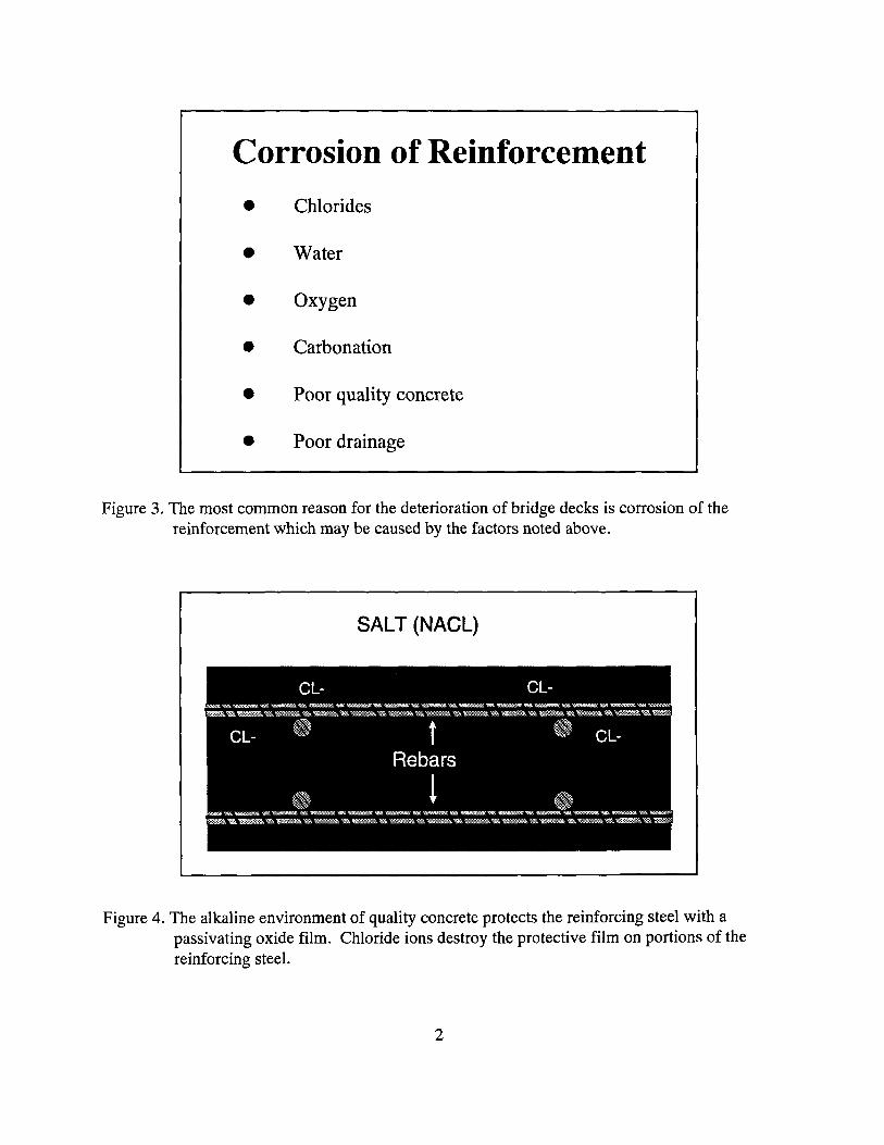
Corrosion of Reinforcement
• Chlorides
• Water
• Oxygen
• Carbonation
Poor quality concrete
Poor drainage
Figure 3. The most common reason for the deterioration of bridge decks is corrosion of the reinforcement which may be caused by the factors noted above.
SALT (NACL)
Figure 4. The alkaline environment of quality concrete protects the reinforcing steel with a
passivating oxide film. Chloride ions destroy the protective film on portions of the reinforcing steel.
2
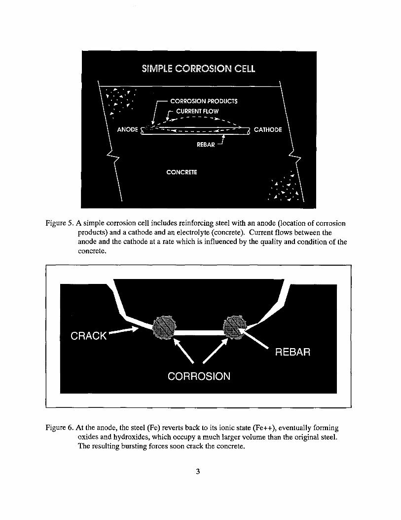
Figure 5. A simple corrosion cell includes reinforcing steel with an anode (location of corrosion products) and a cathode and an electrolyte (concrete). Current flows between the anode and the cathode at a rate which is influenced by the quality and condition of the concrete.
Figure 6. At the anode, the steel (Fe) reverts back to its ionic state (Fe++), eventually forming oxides and hydroxides, which occupy a much larger volume than the original steel. The resulting bursting forces soon crack the concrete.
3

Figure 7. A plugged or improperly located drain (shown above) does not provide for proper drainage. Poor drainage allows water and salt to pond on the surface and to saturate the concrete, which provides ideal conditions for freeze and thaw damage in the concrete and creates high salt concentrations at the reinforcing steel.
Figure 8. Carbonated concrete does not provide the alkaline environment that protects steel. Concrete can carbonate in the vicinity of the reinforcing steel because of cracks and thin, poor quality concrete cover.
4

Performance Model for Reinforced Concrete Exposed to Chlorides
% Deterioration
•ervice Ufe Umit
Corrosion Spalling Fail• •re Initiation Initiation Definition
Time
Figure 9. Steel reinforced concrete structures exposed to chlorides have a service life limit. Prior to making a repair or installing a protection system, a structure should be evaluated to determine the chloride contamination level.
Figure 10. Water expands 9.1 percent when it freezes. Freezing water in saturated concrete
ruptures the concret as shown above unless the concrete has the proper entrained air content to accomodate the expanding water.

Figure 11. Alkali-silica reaction products appear green (white in black and white figure) when uranyl acetate solution is applied to freshly fractured or sawcut surfaces and viewed under ultraviolet light.
Figure 12. Alkali-silica reaction products appear as white rings around reacting aggregates.

Locating Deteriorated Concrete
1. Chain drag (delaminations)
2. Half cell potentials (> 0.35 VSCE)
3. Chloride content measurements (> 21b/yd 3)
Figure 13. Three methods for locating deteriorated concrete include delamination detection methods, such as the chain drag, which locate spalling concrete, and half cell potential and chloride content measurements which are typically used to locate concrete in lower stages of deterioration.
Methods For Locating Delaminations
• Chain Drag
• Hammer
• Pulse Velocity
• Impact echo
• Radar
• Infrared Thermography
Figure 14. Methods used to locate delaminations. The chain drag works well for decks without asphalt overlays. Radar and infrared thermography are used on decks with asphalt overlays.

Figure 15. Several chains hanging from a pipe (chain drag) can be dragged over the deck surface to locate delaminated and very unsound concrete. Noise from traffic cart interfere with the use of the chain drag.
Figure 16. The chain produces a hollow sound when it passes over delaminated concrete because the vibrations are reflected and absorbed by a thinner section than when the concrete is solid.
8

Figure 17. Pulse velocity methods measure the travel time of a pulse. Travel time is shorter over
flaws detected using surface transmission.
Figure 18. Travel time is longer over flaws detected using direct transmission. Travel time decreases as the quality and density of the concrete increases. Travel time may also be less if steel is present in the concrete.
9

Figure 19. Impact echo involves impacting the surface and receiving the reflected waves.
9.99 kHz
13.5 27.0 40.5 54.0 67,5 kHz
Figure 20. The waves are analyzed for dominant frequency and for changes in the frequency response, which indicates flaws.
10

Figure 21. Ground penetrating radar can be used to detect delaminations under asphalt overlays. The delamination causes additional reflections of microwave pulses.
Figure 22. Delaminations and other flaws can be identified by examining the graphic display for irregularities in the reflected microwaves. The display shows the arrival times of the pulses on the vertical scale and the location of the antenna on the horizontal scale.
11
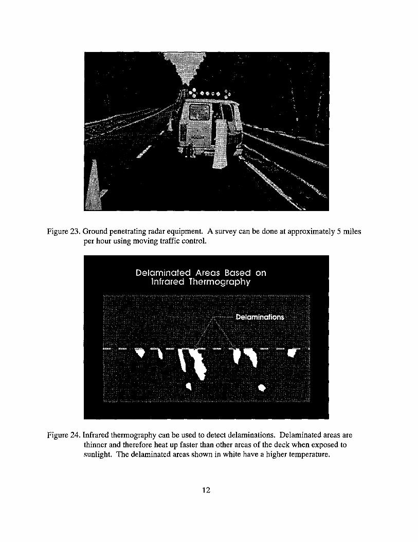
Figure 23. Ground penetrating radar equipment. A survey can be done at approximately 5 miles per hour using moving traffic control.
Figure 24. Infrared thermography can be used to detect delaminations. Delaminated areas are
thinner and therefore heat up faster than other areas of the deck when exposed to sunlight. The delaminated areas shown in white have a higher temperature.
12

Figure 25. Infrared thermography equipment. A survey can be done at 5 mph using moving traffic control.
Figure 26. A deck can be marked off into 4- or 5-ft grids, and copper sulfate half-cell potential measurements can be taken at the grid points to identify areas that have a high potential for corrosion (those with measurements more negative than -0.35 volts). Use of a 2-ft grid reduces the chances of missing a high potential area.
13

Figure 27. Close up of electrical half-cell potential measuring equipment showing a reading of -.134 volts which indicates a low potential for corrosion.
Figure 28. A multiple half-cell array can be used to expedite the collection of data, particularly when measurements are being made on a 2-ft grid.
14

Figure 29. Half-cell potential measurements can be recorded on a datalogger and later downloaded onto a personal computer.
Figure 30. Software is available that can be used to print the half-cell potential data as contours. Data from surveys for cracks and delaminations can also be displayed and printed using a personal computer.
15

Figure 31. Chloride content measurements can be made on samples of pulverized concrete taken in the vicinity of the reinforcement. A pacometer can be used to locate and to provide an indication of the depth of cover over the reinforcement. A drill should be used to
remove the concrete above the sample down to within approximately 1/2 in of the reinforcement. A vacuum can be used to remove concrete from the drill hole.
Figure 32. The drill and core barrel should be returned to the hole, and the sample in the vicinity of the reinforcement should be pulverized. A spoon can be used to collect the sample. A chloride content >2 lb/yd 3 can cause corrosion.
16

Figure 33. Recently developed equipment makes chloride sampling easier and faster. The equipment includes a drill, 1.12 in. diameter hollow drill bit, collection device with coffee filter, vacuum cleaner, hoses, and connections. The sample is collected in the coffee filter as the concrete is drilled.
Concrete Evaluations
• Compressive Strength
• Bond Strength
• Petrographic
• Carbonation
Figure 34. Other evaluations that are useful for identifying deteriorated concrete include the compressive strength of cores, the bond strength of overlays, petrographic examination of cores, and application of a phenolphthalein solution to reveal carbonation on freshly broken pieces of concrete.
17

Other Evaluations
• Visual Inspection
• Cracks
• Joints
• Bearings
Figure 35. Additional evaluations that can be used to locate deteriorated concrete include a visual inspection and examinations of cracks, joints and bearings.
Figure 36. The first step in conducting a bond test of an overlay is to drill through the overlay and at least 3/8 in. into the base concrete (VTM-92). The core barrel should be diamond tipped and directed perpendicular to the concrete surface.
18

Figure 37. Electric heaters or hair dryers can be used to dry the cored concrete surface. Care should be taken to keep the temperature of the concrete below 120 F. Water may be removed from around the cored area using oil free compressed air.
Figure 38. A rapid curing epoxy adhesive should be applied to the cored surface and the bottom of a metal pipe cap just prior to centering the cap over the core. Excess epoxy may be pulled up the sides of the cap but should not be in contact with concrete outside the cored area.
19
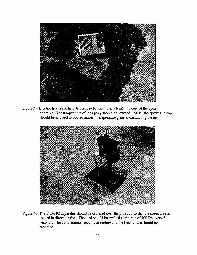
Figure 39. Electric heaters or hair dryers may be used to accelerate the cure of the epoxy adhesive. The temperature of the epoxy should not exceed 120°F. the epoxy and cap should be allowed to cool to ambient temperature prior to conducting the test.
Figure 40. The VTM-92 apparatus should be centered over the pipe cap so that the cored area is loaded in direct tension. The load should be applied at the rate of 100 lbs every 5 seconds. The dynamometer reading at rupture and the type failure should be recorded.
20

Figure 41. A failed core showing 100 bond failure of a 2 in. thick hydraulic cement
concrete overlay.
Figure 42. The tensile rupture strength of the overlay is computed by dividing the load reading by the area of the core.
21

Figure 43. Five types of failures may occur. Excellent bond strength is indicated by tensile strengths of 250 psi or more based on the average of 3 tests. Base type failures at strengths of less than 250 psi should be examined closely. Additional surface preparation is recommended when the depht of failure in the base is less than 1/4 in. Replacement of the base concrete is recommended when the strength is less than 150 psi.
Figure 44. A guillotine shear apparatus can be used to measure the shear bond strength of 4-in diameter cores removed from a deck or overlay specimens prepared in the laboratory.
22
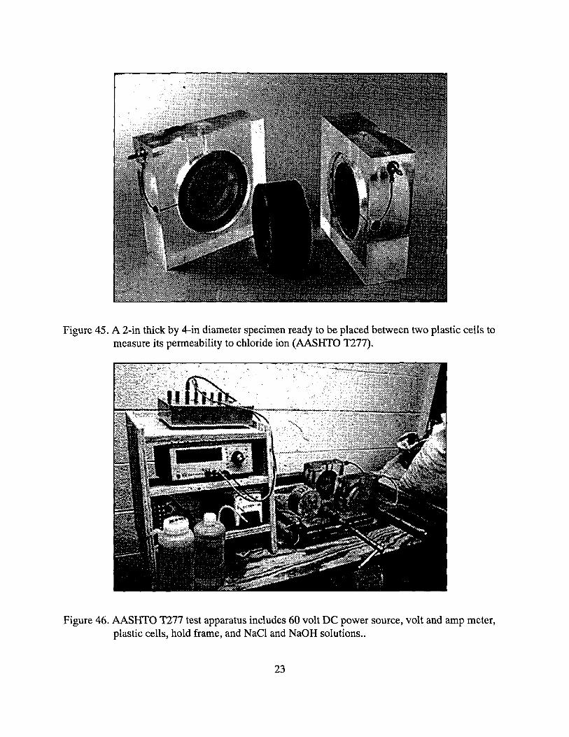
Figure 45. A 2-in thick by 4-in diameter specimen ready to be placed between two plastic cells to
measure its permeability to chloride ion (AASHTO T277).
Figure 46. AASHTO T277 test apparatus includes 60 volt DC power source, volt and amp meter, plastic cells, hold frame, and NaC1 and NaOH solutions..
23

Figure 47. Spalling deterioration on a 30 year old prestressed concrete beam bridge.
Figure 48. Prestressed strands are corroded and concrete is not properly consolidated in spalled areas of beam.
24
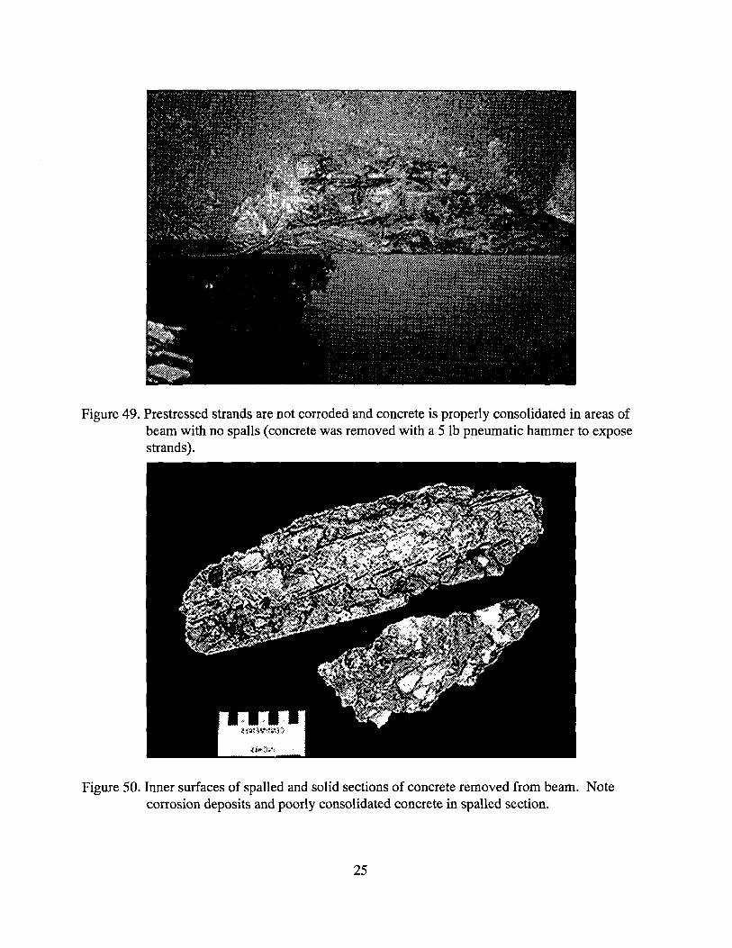
Figure 49. Prestressed strands are not corroded and concrete is properly consolidated in areas of beam with no spalls (concrete was removed with a 5 lb pneumatic hammer to expose strands).
Figure 50. Inner surfaces of spalled and solid sections of concrete removed from beam. Note corrosion deposits and poorly consolidated concrete in spalled section.
25

Figure 51. Vacuum chloride sampling equipment is used to take concrete samples from the side of the prestressed concrete beam.
PRESTRESSED CONCRETE I BEAMS
CHLORIDE CONTENT AT 30 YEARS (LB/YD 3)
CONSOLIDATION
DEPTH(IN.) GOOD POOR
0 0.5 3.04 3.02 0.5- 1.0 0.77 1.99 1.0 -1.5 0.53 1.69
Figure 52. Chloride ion content as a function of depth for samples taken from spalled and solid areas of prestressed beam. Based on the condition of the strands and the chloride content in the vicinity of the strands in the solid areas the beams can be repaired.
26

Removing Deteriorated Concrete
Patches
1. Mark areas
2. Saw perimeter
3. Pneumatic hammers (30 lb maximum)
4. Sandblasting
Overlays
1. Scarification
2. Sandblasting
3. Shotblasting
4. Hydrodemolition
Figure 53. Once the cause of deterioration has been determined and a procedure for locating the deteriorated concrete has been identified, the deteriorated concrete can be removed using the procedures noted above. When patching is necessary, the perimeter should be marked and sawcut. Pneumatic hammers weighing less than 30 lbs may be used to
remove the concrete. Scarification, sandblasting, shotblasting, and waterblasting may be used to remove concrete and prepare the surface for an overlay.
27

Figure 54. The area over which the concrete is to be removed should be "squared up" and marked with paint.
Figure 55. A saw should be used to cut the concrete to a depth of I in (or to a depth that will clear the rebar) along the perimeter of the area to be removed.
28

Figure 56. Pneumatic hammers weighing •30 lbs should be used at an angle of 45 to 60 to dislodge the deteriorated concrete in areas to be patched. When rebar is exposed, the concrete shall be removed to a depth of• 1 in below the rebar.
Figure 57. Prior to placing hydraulic cement concrete overlays, a cold milling machine can be used to remove concrete above the reinforcement. The impact heads of the scarifier shown above can fracture the concrete that is left in place. Care should be taken to
remove the fractured concrete. Hand-held pick hammers and heavy grit blasting can
be used to remove some of the fractured concrete.
29
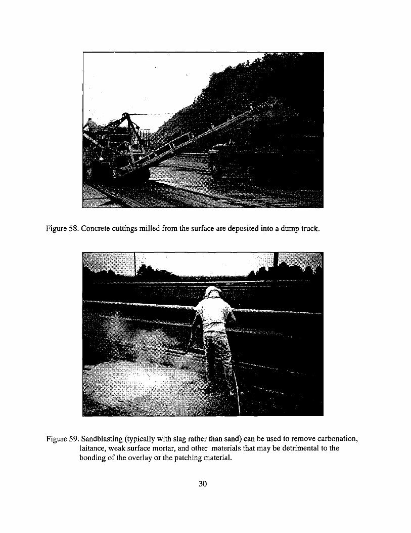
Figure 58. Concrete cuttings milled from the surface are deposited into a dump truck.
Figure 59. Sandblasting (typically with slag rather than sand) can be used to remove carbonation, laitance, weak surface mortar, and other materials that may be detrimental to the bonding of the overlay or the patching material.
30

Figure 60. A schematic of a shotblasting unit that can be used to blast the surface with steel shot and to recover the shot and cuttings from the surface.
Figure 61. Shotblast equipment is available in a range of sizes. Units that blast a 9-in-wide strip and a 6-ft-wide strip are shown above.
31

Figure 62. The degree of cleaning obtained with shotblast equipment is a function of the forward speed, the number of passes, the size of the shot, and the gate opening. Once the
proper setting is identified, the entire surface should be cleaned at that setting. A slow speed or multiple passes are required to obtain the exposed aggregate surface shown above. The lighter cleaning (top of figure) was obtained by increasing the forward speed of the blaster. It is usually necessary to expose the coarse aggregate to obtain adequate bond strength.
Figure 63. A tank truck can be used to supply water required for hydrodemolition.
32

Figure 64. A high pressure water jet moves from left to right inside the blasting unit, thereby removing concrete with a strength that is lower than the pressure of the water. The jet must be calibrated to give the desired depth of removal.
Figure 65. View of the forward end of the hydrodemolition equipment.
33

Figure 66. Concrete can be dislodged and reinforcement can be cleaned by hydro demolition. The dislodged concrete and water must be removed from the surface prior to placing the overlay or repair material. Vacuums, shovels, and air blasting have been used to
remove contaminants. Proper containment and disposal of blast water and concrete rubble is necessary.
Checking for Adequate Surface Preparation
1. Visual Inspection
2. Chipping Hammer
3. Tape Test
4. VTM92 tensile adhesion test
5. Shear test on cores
Figure 67. Prior to patching or placing an overlay, surfaces should be checked for adequate surface preparation.
34

Figure 68. Black electrical tape can be applied to the blasted surface and removed and examined to identify dust that could interfere with the bonding of an overlay or repair material. An acceptable surface will only leave traces of dust on the sticky side of the tape (see tape on left above). The surface should be airblasted with oil-free compressed air to
remove dust.
Figure 69. VTM92 can be used to measure the tensile adhesion strength of overlays.
35

Figure 70. A guillotine shear apparatus can be used to measure the shear bond strength of 4-in diameter cores removed from a deck or overlay specimens prepared in the laboratory.
Hydraulic Cement Concrete Patches
1. Type A (rebar not exposed)
2. Type B (rebar exposed, < 1/2 deck thickness)
3. Type C (full depth)
Figure 71. Three types of hydraulic cement concrete patches are used on bridge decks.
36

Epoxy Mortar Patches
1. Type D(<3/4 thick)
Figure 72. Epoxy mortar patches are typically used to correct surface defects that are less than 3/4 in. thick.
Figure 73. Areas to be patched with epoxy mortar shall be dry and shall be primed with neat
epoxy prior to placing the mortar.
37

Figure 74. Type B patches (approximately 1/2 deck thickness), illustrating that the area to be patched has been squared up, the perimeter has been sawed to a depth of 1 in, the concrete has been removed with pneumatic hammers to a depth of 1 in. below the transverse reinforcing bars, and the surfaces of the concrete and reinforcement have been blasted with slag. Concrete does not have to be removed from below longitudinal reinforcing bars that are bonded to the concrete and not corroded.
Figure 75. Type C patches (full depth) require forms to be suspended from reinforcing steel (areas <3 ft 2) or supported by blocking from beam flanges.
38

Ready Mix Hydraulic Cement Concrete Patching Materials Packaged, Rapid Hardening Hydraulic Cement Concrete
Materials
1.Rapid Hardening (>2000 psi in 6 hr)
2.Very Rapid Hardening (>2,500 psi in 2 hr)
Figure 76. Patching can be done with ready mix hydraulic cement concrete when large quantities of concrete are required. Packaged, very rapid hardening materials are typically used when small quantities of concrete are needed.
Figure 77. With proper planning, special blended cements that meet the requirements for rapid hardening materials can be mixed in 1 to 2 yd 3 batches in ready mix trucks.
39

Figure 78. Prior to placing the hydraulic cement concrete patching material, the hardened concrete surfaces and reinforcing steel shall be grit blasted to remove carbonation, laitance, rust and other materials that may be detrimental to the bonding or curing of the fresh concrete.
Figure 79. The hydraulic cement concrete shall be properly consolidated with internal vibrators and a vibrating screed may be used to strike off the surface.
40

Figure 80. White pigmented liquid membrane curing material shall be applied to the freshly placed concrete surface as soon as practical to prevent the loss of moisture and subsequent shrinkage cracking of the concrete.
Figure 81. Prepackaged, very rapid hardening hydraulic cement concrete materials are typically used for small Type A and Type B patches. A small concrete mixer can be used to mix the cement, fine and coarse aggregate, and water. Calibrated containers should be used to measure out the required weight of each ingredient.
41

Figure 82. The mixed concrete is usually transported to the patch site with a wheelbarrow. Internal spud vibrators must be used to consolidate the concrete. The mixture should have a slump of 2 to 4 in. and should not segregate when consolidated. The hardened concrete surface should be wetted to achieve a saturated-surface-dry condition prior to placing the fresh concrete.
Figure 83. The concrete may be struck-off with a straight edge. When several batches are used to fill a large patch, the concrete should be struck off as each batch is placed.
42
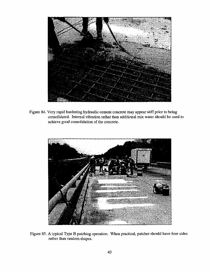
Figure 84. Very rapid hardening hydraulic cement concrete may appear stiff prior to being consolidated. Internal vibration rather than additional mix water should be used to achieve good consolidation of the concrete.
Figure 85. A typical Type B patching operation. When practical, patches should have four sides rather than random shapes.
43

Length Change (%]
-o.o6••.i•..;;•.•i -o.•o• • •
4 8 12 18 20 24 28 32 Age (months)
Figure 86. Shrinkage as a function of age for concretes made with different quantities of a special blended cement. Shrinkage increases as the cement content increases.
Curing Time vs. Temperature Time required for 2500 psi compressive strength (hours)
Curing Temperature (°F)
Material 40 50 90 SBC 1 5.0 1.7 0.6
SBC 2 3.6 2.2 0.6
SBC 3 6.2 3.4 2.4
Figure 87. Curing Time as a function of Curing Temperature for three special blended cement
concretes. Curing time increases as temperature decreases. Some mixtures may not be placeable at elevated temperatures and other mixtures may require extended lane closure time for proper use.
44

Compressive Strength vs. Age Special Blended Cement Ready Mix
Concrete (10 bags/yd 3)
Age Strength (psi) 3 hours 2,760
4 hours 3,080
5 hours 3,360
24 hours 6,090
28 days 10,380
Figure 88. Compressive Strength vs. Age for a special blended cement ready mix concrete.
Figure 89. Temperature vs. Age for a Type Ill cement full depth patch. The temperature of the patch is much higher than that of the air or of ambient cured cylinder. To be representative of the path, cylinders must be temperature matched cured with the patch.
45
6
TMC Proprietary TMC Cyl.
• / Patch Top Cyl.
............. •
/ •: Cure Cyl.
o
5 7 9 11 13 15 17 19 21 23
Time (Hours)
Patch Top Cyl. TMC Proprietary TMC Cyl. Ambient Cure Cyl.
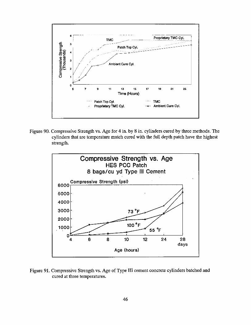
Figure 90. Compressive Strength vs. Age for 4 in. by 8 in. cylinders cured by three methods. The cylinders that are temperature match cured with the full depth patch have the highest strength.
Compressive Strength vs. Age HES PCC Patch
8 bags/cu yd Type III Cement
Compressive Strength (psi) 6000
50OO
4000
3000
2000
1000
£ 4
73 OF
6 8 10 12 24 28 days
Age (hours)
Figure 91. Compressive Strength vs. Age of Type III cement concrete cylinders batched and cured at three temperatures.
46
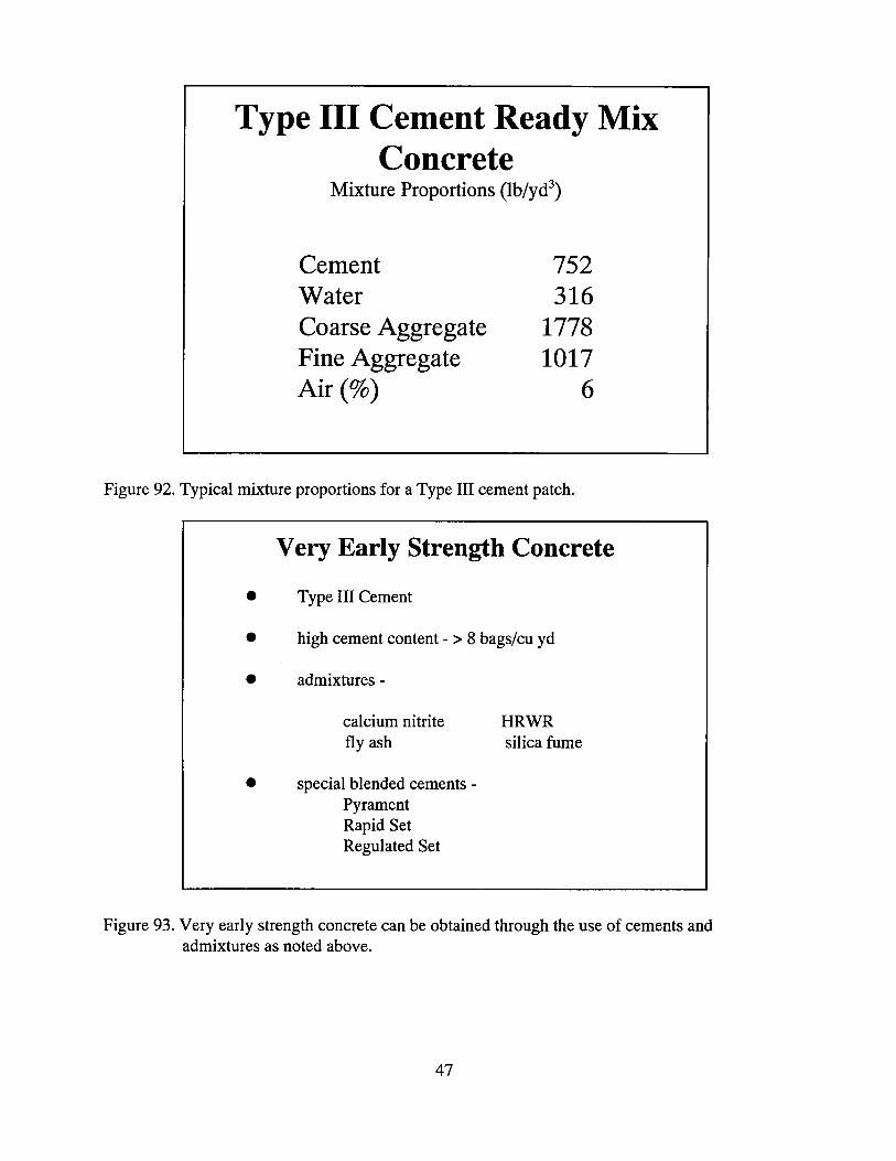
Type III Cement Ready Mix Concrete
Mixture Proportions (lb/yd 3)
Cement 752 Water 316 Coarse Aggregate 1778 Fine Aggregate 1017 Air (%) 6
Figure 92. Typical mixture proportions for a Type III cement patch.
Very Early Strength Concrete
• Type III Cement
• high cement content > 8 bags/cu yd
• admixtures
calcium nitrite HRWR fly ash silica fume
• special blended cements Pyrament Rapid Set Regulated Set
Figure 93. Very early strength concrete can be obtained through the use of cements and admixtures as noted above.
47

HIGH QUALITY CONCRETES
OPTIMUM MIXTURE PROPORTIONS
QUALITY AGGREGATES
LOW WATER TO CEMENT RATIOS
ADMIXTURES, POZZOLANS, FIBERS
Figure 94. High quality concretes can be obtained with optimum mixture proportions, quality aggregates, low water to cement ratios, and admixtures.
HYDRAULIC CEMENT CONCRETE
SILICA FUME, 7%
FLY ASH, 15%
SLAG, 35% TO 50%
FIBERS, PLASTIC/STEEL
CORROSION INHIBITORS
Figure 95. Durable, corrosion resistant, hydraulic cement concretes are obtained by replacing portland cement with silica fume, fly ash, slag, and by adding fibers and corrosion inhibitors.
48
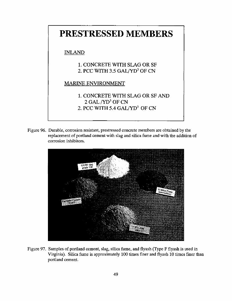
PRESTRESSED MEMBERS
INLAND
1. CONCRETE WITH SLAG OR SF 2. PCC WITH 3.5 GAL/YD 3 OF CN
MARINE ENVIRONMENT
1. CONCRETE WITH SLAG OR SF AND 2 GAL/YD 3 OF CN
2. PCC WITH 5.4 GAL/YD 3 OF CN
Figure 96. Durable, corrosion resistant, prestressed concrete members are obtained by the replacement of portland cement with slag and silica fume and with the addition of corrosion inhibitors.
Figure 97. Samples of portland cement, slag, silica fume, and flyash (Type F flyash is used in Virginia). Silica fume is approximately 100 times finer and flyash 10 times finer than portland cement.
49

Figure 98. Placement of concrete to widen a bridge deck. Silica fume, fly ash and slag are being used in concrete to reduce the lifecycle costs, to obtain high early strengths (silica fume), and to utilize materials that might have to be placed in landfills.
Figure 99. White, pigmented liquid membrane curing material must be applied to bridge deck concrete, except, latex modified concrete, following the removal of the wet burlap to continue the cure of the concrete.
50

Figure 100. ACI nomograph for estimating evaporation rate. The higher the evaporation rate, the greater the probability that plastic shrinkage cracks will occur.
Figure 101. Concrete in the center span is cracked full depth because white pigmented liquid membrane curing material was not applied in sufficient quantities.
51

Figure 102. Carbonation stains surface from a cracked and delaminated overlay. Cracks in overlays typically result in delaminations of the overlay in the vicinity of the cracks.
Sealing Cracks
1. Gravity Fill
a. High Molecular weight methacrylate
b. Epoxy c. Urethane
2. Route and Seal
3. Pressure Injection: Epoxy
4. Vacuum Injection: Methacrylate
Figure 103. Four methods that can be used to seal cracks.
52

Figure 104. Random oriented shrinkage cracks prior to the application of a gravity fill polymer.
Figure 105. High molecular weight methacrylate resin can be applied to the surface of a bridge deck with brooms to fill random cracks such as those caused by plastic shrinkage. An effort should be made to brush the resin into the cracks until the cracks appear to be filled by the brooming action and the force of gravity.
53

Figure 106. Sand must be broadcast onto the resin to provide an acceptable skid number. The sand may be omitted if the resin is applied to a grooved or tined surface, but care
must be taken to ensure that the resin does not fill the grooves.
Figure 107. High molecular weight methacrylate can be applied to a crack. For satisfactory filling of the crack, it should be free of debris and wider than 0.1 mm. Also, best results can be obtained by filling cracks when they are open the widest at the surface (temperatures between 55°F and 70°F and between 1:00 a.m. and 10:00 a.m). High molecular weight methacrylate will not cure satisfactorily at temperatures below 55 °F.
54

Figure 108. A pressurized spray can be used to apply high molecular weight methacrylate resin to
a crack. For best results, a brush should be used to work the resin into the crack. Protective clothing should be worn to keep the resin off of the skin.
Figure 109. High molecular weight methacrylate resin is here applied to a crack in a deck with a
tined texture. Excess resin should be spread with a broom to prevent filling the grooves, which can cause a reduction in skid resistance.
55

Figure 110. A two component, rapid curing, urethane, gravity fill monomer is applied to cracks using a double cartridge gun.
Products
Epoxy 1
Epoxy 2
Epoxy 3
Urethane
HMWM
Cost (per gal.)
$18
$80
$33-50
$67-90
$40
Mix Ratios (By Vol.)
A:2 B:I
A:2 B:I
A:3.5 B:I.0
A:I B:I
A:91-94% B:2% C:4-7%
Viscosity (cps)
175-250
200-230
300-500
A:12 B:16
<100
Odor
Stinky
Mild
Stinky
Almost None
Extremely Pungent
Figure 111. Gravity-fill polymer crack sealers include epoxies, urethanes, and high-molecular- weight methacrylate. HMWM penetrates the best but is the most difficult to mix.
56

REPAIR GUIDELINES
Preplace dry, No. 50 sieve size sand in cracks with a
width greater than 1 mm.
Place monomers prior to 9:00 a.m. and during colder weather when cracks are widest.
Cracked concrete surfaces should be dry and sound.
Air blast or water blast cracks prior to placing the
monomers.
Broom monomers into crack until the crack is full.
Figure 112. Guidelines for the repair of cracks using gravity-fill polymers.
Figure 113. A two-component epoxy is here injected into a crack under pressure. Prior to injecting the epoxy, the crack should be covered above and below with a viscous paste-like epoxy and injection ports should be spaced at a distance equal to the depth of the crack to be injected. The requirements for successful filling of a crack cited under Figure 107 are also generally applicable to pressure injection.
57

Figure 114. Vacuum injection can be used to fill cracks with a methacrylate resin. Prior to introducing the resin, steel entry ports should be placed on the crack surface, the cracks are covered above and below with a viscous paste-like epoxy, and a vacuum
is applied to the cracks through the ports. The requirements for successful filling of
a crack cited under Figure 107 are also generally applicable to vacuum injection.
Figure 115. Joints in bridges must be repaired to prevent chlorides and water from reaching beams and substructure elements, to prevent incompressible materials from restricting movement, and to provide a smooth and safe riding surface.
58

Figure 116. Deterioration of concrete caused by water and chlorides leaking through a joint.
Figure 117. Corrosion induced spalling on a pier caused by chlorides leaking through a joint.
59

Figure 118. The first step in a joint repair is to sawcut the concrete on both sides of the joint so
that the joint and adjacent concrete can be removed.
Figure 119. A typical construction sequence includes removal of old joint and adjacent concrete, grit blasting the concrete to provide for good adhesion, placing the joint assembly, and placing the new concrete.
60

Figure 120. Once the concrete headers
are cured, an adhesive is typically placed on the wails of the headers and a
compression seal is placed.
Figure 121. A joint is replaced with polymer concrete headers. Once the polymer concrete has cured the center styrefoam form is removed, adhesive is applied to the walls of the headers, and a pressurized joint seal is installed.
61

Figure 122. Pressurized joint seal is deflated so that it can be installed between polymer concrete headers.
PROTECTION SYSTEMS
• LATEX MODIFIED CONCRETE OVERLAYS
• SILICA FUME CONCRETE OVERLAYS
• POLYMER CONCRETE OVERLAYS
• ASPHALT OVERLAY WITH MEMBRANE
• SEALERS
• CATHODIC PROTECTION
Figure 123. The basic systems used to protect bridge decks from chloride induced corrosion.
62

Latex Modified Portland Cement Overlay
(Mobile Concrete Mixer)
1. Standard latex modified concrete
2. High early strength latex modified concrete
3. Slurry
Figure 124. The standard latex-modified concrete overlay, made with Type II cement, has been used since the 1960's. High early strength overlays, made with Type III cement, were
first used in 1986. The slurry system, first used in 1989, is the standard latex- modified concrete without the coarse aggregate. Also, it is not a protective system but rather a 1/4 in. thick skid resistant surface.
63

Figure 125. A mobile concrete mixer can be placed on a deck surface that has been prepared for application of a latex modified concrete overlay. The surface should be scarified, patched, sandblasted (48 hours prior to application of overlay), sprayed with water, and covered with polyethylene at least 1 hour prior to placement to obtain a sound, clean, saturated surface dry condition (saturated deck with no free water on the surface). The truck usually has compartments that contain coarse aggregate, fine aggregate, cement, latex, and water. The ingredients are usually conveyed to an
auger type mixer and mixed just prior to being discharged onto the deck surface. The truck must be calibrated to provide the desired mixture. District Materials personnel should approve the calibration. Requirements for preparing the concrete surface and placing and curing the concrete can be found in Sections 404.04 and 412.03 of the Road and Bridge Specification.
64

Figure 126. The latex modified concrete should be discharged onto the deck surface as the layer of polyethylene is rolled back. Brooms should be used to brush the mortar fraction of the concrete into the base concrete just ahead of the placement. A transverse rotating drum-type screed that moves back and forth can be used to consolidate, strike off, and finish the concrete. Internal spud vibrators should be used to consolidate the concrete along the edges (the centerline and the parapet), in deep pockets (patches), and adjacent to joints. Hand floats may be used to strike off and finish the concrete along the edges.
Figure 127. Screeds have vibrating rollers or a vibrating pan as shown here that consolidates the concrete. The vibrating parts should be checked periodically during the overlay placement to insure proper vibration (3000 to 6000 vibr. per minute) is being applied to the concrete.
65

Figure 128. Wet burlap should be applied to the surface as soon as the tining operation is complete. The burlap should be applied as soon as possible to prevent evaporation of water from the mixture, which can cause plastic shrinkage cracks.
Figure 129. The wet burlap should be covered with polyethylene as soon as possible to prevent water from evaporating from the burlap. The wet burlap and polyethylene should be left in place for 24 to 48 hours. The burlap should be kept moist during the curing period.
66
0 5' C) 0
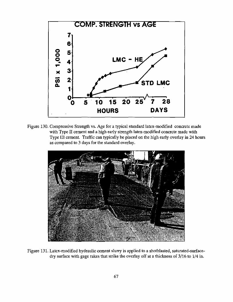
COMP. STRENGTH vs AGE
LMC HE
;TD LMC
O0 5 10 15 20 25 7 28
HOURS DAYS
Figure 130. Compressive Strength vs. Age for a typical standard latex-modified concrete made with Type II cement and a high early strength latex-modified concrete made with Type III cement. Traffic can typically be placed on the high early overlay in 24 hours
as compared to 3 days for the standard overlay.
Figure 131. Latex-modified hydraulic cement slurry is applied to a shotblasted, saturated-surface- dry surface with gage rakes that strike the overlay off at a thickness of 3/16 to 1/4 in.
67

Figure 132. The latex-modified hydraulic cement slurry is tined with 1/8 in. wide by 1/8 in. deep grooves spaced 3/4 in. on center to provide a skid resistant surface.
Figure 133. Silica fume concrete is mixed in a ready-mix truck and deposited onto a bridge deck surface that has been prepared the same way as the surface is prepared for a latex- modified concrete overlay (see Figure 125).
68
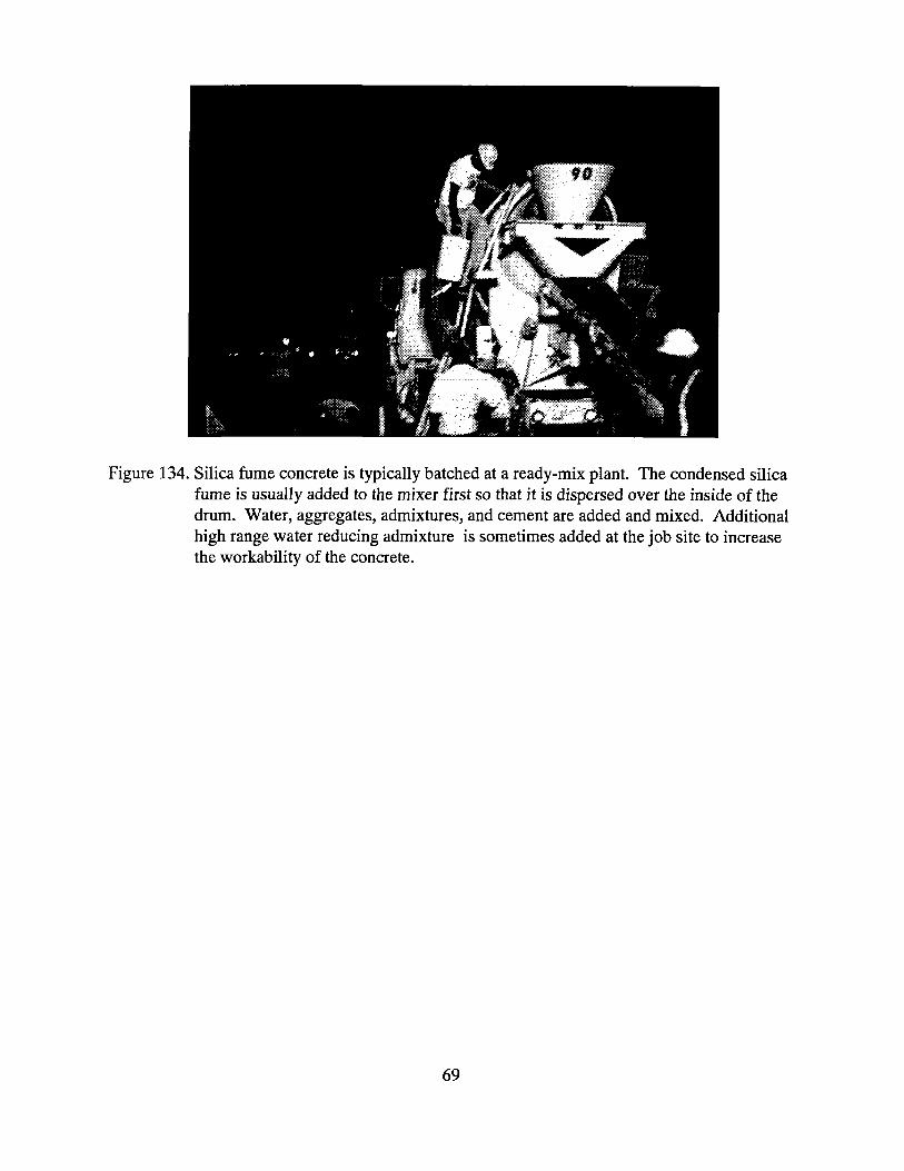
Figure 134. Silica fume concrete is typically batched at a ready-mix plant. The condensed silica fume is usually added to the mixer first so that it is dispersed over the inside of the drum. Water, aggregates, admixtures, and cement are added and mixed. Additional high range water reducing admixture is sometimes added at the job site to increase the workability of the concrete.
69

Figure 135. Silica fume concrete is here discharged onto the deck surface. The surface has been prepared in the same way it would be prepared for a latex modified concrete overlay (see Figure 125). The installation of the overlay is the same as described in Figures 126 through 129 for a latex-modified concrete overlay except that the wet burlap and polyethylene is left in place for 7 days and a white, pigmented, liquid membrane curing material is applied as the burlap is removed. Compressive strengths greater than 3,000 psi can be obtained in 24 hours with concrete mixtures containing 7 percent silica fume by weight of cementitious materials. Both latex modified concrete and silica fume concrete can be used to produce overlays with a
permeability to chloride ion (AASHTO T277) of less than 1,000 Coulombs.
70
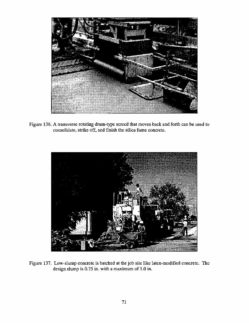
Figure 136. A transverse rotating drum-type screed that moves back and forth can be used to consolidate, strike off, and finish the silica fume concrete.
Figure 137. Low-slump concrete is batched at the job site like latex-modified concrete. The design slump is 0.75 in. with a maximum of 1.0 in.
71

Figure 138. Prior to placing a low-slump hydraulic cement concrete overlay, the surface is shot blasted or grit blasted to remove contaminants that can interfere with the bonding and curing of the concrete. A grout, consisting of 1 part cement and I part fine aggregate and sufficient water to make a stiff slurry, is scrubbed into the dry concrete surface just ahead of the screed.
Figure 139. A special vibrating screed is required to consolidate and strike off low slump concrete. The screed should be checked periodically to insure that it is providing adequate vibration. The screed shall consolidate the overlay to 100 percent of the dry rodded unit weight. A white pigmented curing material is applied to the screeded surface and followed by wet burlap.
72

Figure 140. Prior to placing an overlay on a major bridge, test panels of candidate overlay mixtures should be installed so that problems with surface preparation, mixture proportions, placement, and curing procedures can be identified.
Figure 141. Tensile bond tests are here performed on an overlay test panel (VTM 92, ACI 503R). Four in. diameter cores have also been taken for rapid chloride permeability tests (AASHTO T277).
73
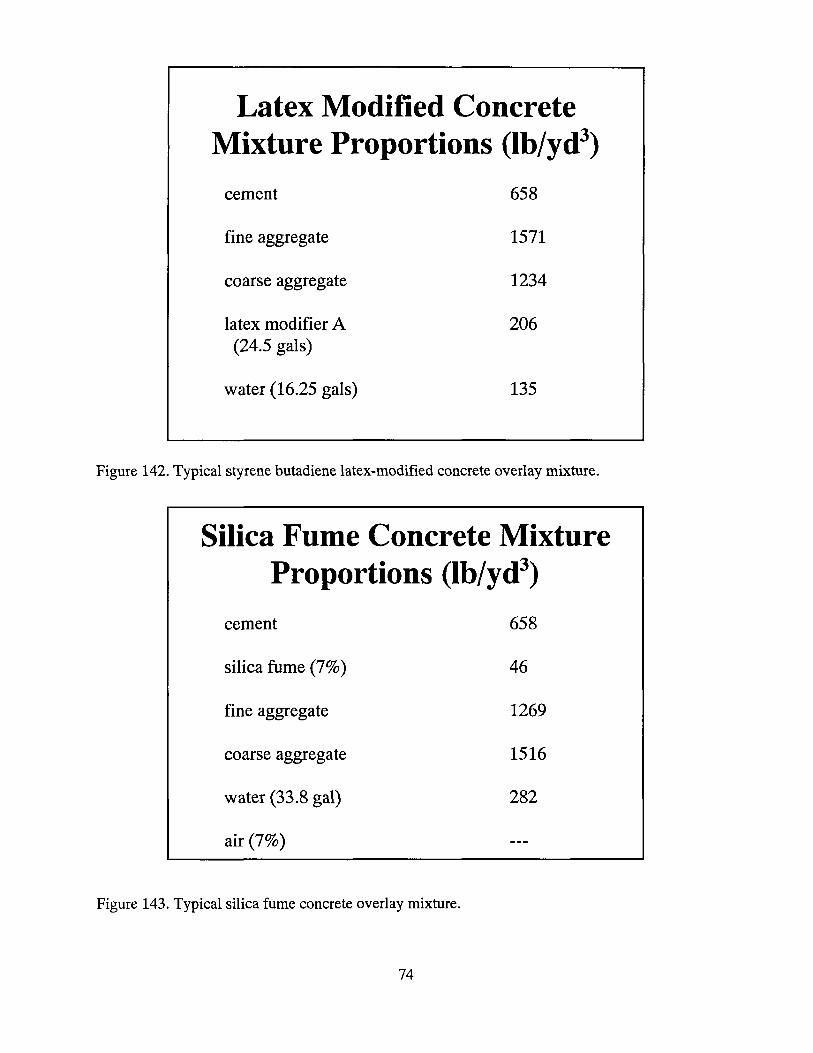
Latex Modified Concrete Mixture Proportions (lb/yd •) cement 658
fine aggregate 1571
coarse aggregate 1234
latex modifier A 206 (24.5 gals)
water (16.25 gals) 135
Figure 142. Typical styrene butadiene latex-modified concrete overlay mixture.
Silica Fume Concrete Mixture Proportions (lb/yd 3)
cement 658
silica fume (7%) 46
fine aggregate 1269
coarse aggregate 1516
water (33.8 gal) 282
air (7%)
Figure 143. Typical silica fume concrete overlay mixture.
74

Low-Slump Dense Concrete Mixture Proportions (lb/yd 3)
cement 825
fine aggregate 1392
coarse aggregate 1392
water (32.4 gal) 270
air (6%)
Figure 144. Typical low-slump dense concrete overlay mixture. (Iowa DOT).
POLYMER CONCRETE OVERLAY TYPES
MULTIPLE LAYER
• SLURRY
• PREMIXED
Figure 145. Three types of polymer concrete overlays.
75

Figure 146. The first step toward the successful placement of a polymer concrete overlay is to shot blast the concrete surface. Shot blast equipment is available in a range of sizes. Units that blast a 9-in-wide strip and a 6-ft-wide strip are shown above.
Figure 147. A multiple layer epoxy overlay consists of two layers of epoxy and aggregate. An
epoxy mixture is here spread over the deck with notched squeegees. Basalt aggregate is here broadcast to excess from the back of a dump truck.
76

Figure 148. Prior to shotblasting the entire bridge deck surface, areas for test patches should be shotblasted and patches constructed and tested so that problems with surface preparation, materials, and mixing and placing procedures can be identified (VTM- 92). Epoxy for the first layer of a test patch is here placed.
Figure 149. Silica sand is broadcast onto the final layer of epoxy of the test patch. The patches should be constructed with the same materials and equipment that will be used for the full scale overlay. Also, they should be constructed under the same conditions if practical.
77
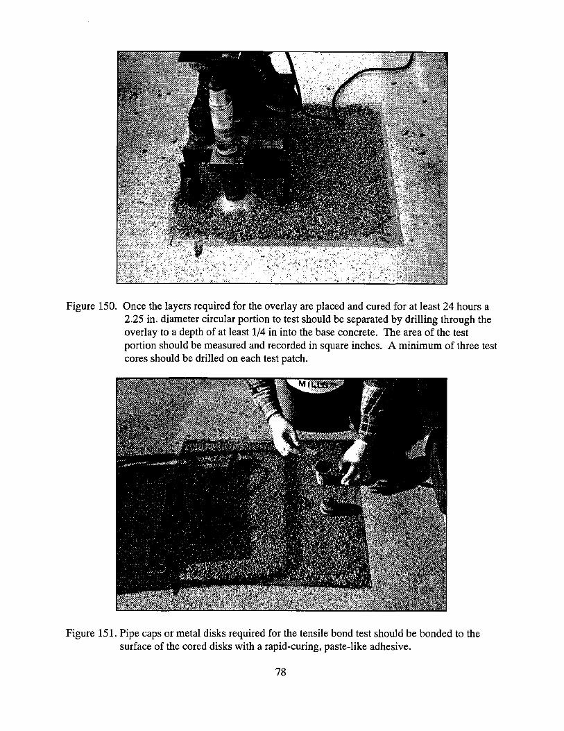
Figure 150. Once the layers required for the overlay are placed and cured for at least 24 hours a
2.25 in. diameter circular portion to test should be separated by drilling through the overlay to a depth of at least 1/4 in into the base concrete. The area of the test portion should be measured and recorded in square inches. A minimum of three test
cores should be drilled on each test patch.
Figure 151. Pipe caps or metal disks required for the tensile bond test should be bonded to the surface of the cored disks with a rapid-curing, paste-like adhesive.
78
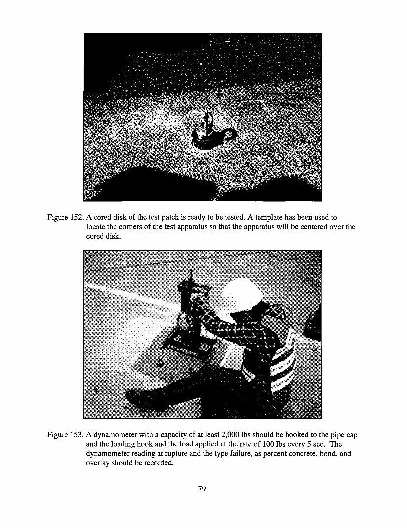
Figure 152. A cored disk of the test patch is ready to be tested. A template has been used to locate the corners of the test apparatus so that the apparatus will be centered over the cored disk.
Figure 153. A dynamometer with a capacity of at least 2,000 lbs should be hooked to the pipe cap and the loading hook and the load applied at the rate of 100 lbs every 5 sec. The dynamometer reading at rupture and the type failure, as percent concrete, bond, and overlay should be recorded.
79

Figure 154. The failure stress should be computed by dividing the dynamometer reading in pounds at rupture by the test area. The average of three tests performed on each test patch should equal or exceed 250 psi. A failure in the base concrete at a depth greater than 1/4 in and at a rupture strength less than 250 psi is indicative of a low strength substrate and not of inadequate surface preparation and should be considered as a passing test result.
Figure 155. Binders for epoxy concrete overlays are usually 1 to 1 or 2 to i mixtures. Care should be taken to carefully measure out the desired quantities of component A and component B. Individual components should be mixed prior to being dispensed into calibrated containers. Protective clothing should be worn so that epoxy does not make contact with the skin.
80

Figure 156. Component A and component B should be added to a mixing container and mixed with a paddle type mixer for several minutes (or as recommended by the manufacturer) to insure complete mixing.
Figure 157. Epoxy components are mixed.
81

Figure 158. Epoxy should be applied to the deck surface immediately after it is mixed and spread over a premarked area with notched squeegees to insure a uniform application at the specified application rate. Prior to placing the epoxy overlay, or any type of polymer overlay, the surface should be shotblasted to remove oil, carbonation, laitance, weak surface mortar, and other materials that can interfere with the bonding of the overlay (see Figure 146).
Figure 159. A 50 mL sample of mixed epoxy should be taken from each batch and the gel time recorded. The gel time is the difference between the initial mixing time and the time the sample turns from a liquid to a gel-like consistency. Similar gel times for batches provides an indication that the materials, batching, and mixing procedures are uniform.
82

Figure 160. The first layer of a multiple-layer epoxy overlay is here constructed. An epoxy mixture is here spread over the deck with notched squeegees. Basalt aggregate is broadcast to excess from the back of a dump truck.
Figure 161. Gel samples are paced along the bridge parapet as the first layer of a multiple-layer epoxy overlay is placed. Silica sand is broadcast from the back of a dump truck.
83

Figure 162. A sweeper-broom type vacuum truck can be used to remove excess aggregate prior to placing the next layer of a multiple-layer epoxy overlay.
Figure 163. A mechanical sweeper can be used to remove excess aggregate prior to placing the second layer or opening the second layer to traffic.
84

Figure 164. Basalt aggregate is broadcast from a dump truck in the adjacent lane as a multiple layer epoxy overlay is constructed
Figure 165. For convenience, polymer concrete overlays may be placed over the joints. The overlay must be sawed over the joint the same day the overlay is placed so
that movements of the adjacent spans do not crack and delaminate the overlay.
85

Figure 166. Methyl methacrylate aggregate slurry mixed with mortar mixers is here applied to shotblasted surface that was primed at least 1 hour earlier with a methyl methacrylate primer. The primer must be cured prior to placing the slurry.
Figure 167. A methyl methacrylate slurry overlay should be struck off with gage rakes set to provide a 3/16 in thick layer of slurry.
86

Figure 168. Aggregate should be broadcast to excess onto the slurry within 5 minutes after the slurry is placed.
Figure 169. Polyester styrene resin is here added to the concrete mixer.
87

Figure 170. Methyl ethyl ketone peroxide initiator is here added to the mixer at the required dosage which is typically 1.0 to 1.5 percent by weight of resin.
Figure 171. Prepackaged aggregate is here added to concrete mixer.
88

Figure 172. Premixed polyester styrene resin concrete is here discharged into buggy.
Figure 173. Premixed polyester styrene resin concrete may be consolidated and struck off with a transverse vibrating screed. The overlay is typically 0.5 to 1.0 in. thick.
89
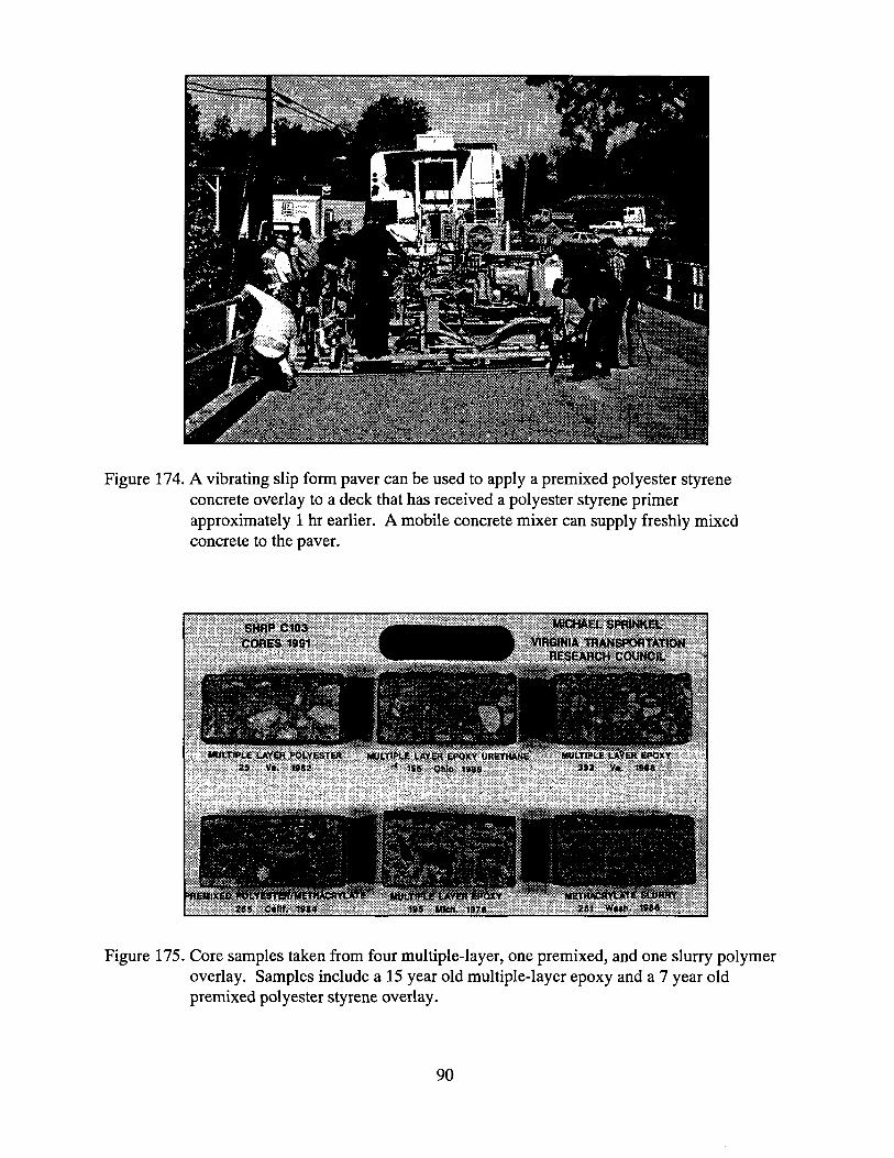
Figure 174. A vibrating slip form paver can be used to apply a premixed polyester styrene concrete overlay to a deck that has received a polyester styrene primer approximately 1 hr earlier. A mobile concrete mixer can supply freshly mixed concrete to the paver.
Figure 175. Core samples taken from four multiple-layer, one premixed, and one slurry polymer overlay. Samples include a 15 year old multiple-layer epoxy and a 7 year old premixed polyester styrene overlay.
90

Asphalt Concrete Overlays
1. On resinous membrane (Class I waterproofing)
2. On prefabricated or liquid membrane (Class II waterproofing)
Figure 176. Asphalt concrete overlays on resinous and preformed membranes are sometimes used to protect bridge decks. A resinous membrane is similar to a multiple layer epoxy overlay and an asphalt overlay is placed if necessary to improve ride quality.
Figure 177. Squeegees can be used to apply a primer to a shotblasted deck prior to placing the prefabricated membrane for Class II waterproofing.
91

Figure 178. A prefabricated membrane should be placed on the primer. Care must be exercised to lap the joints to minimize wrinkles in the membrane and to eliminate air pockets under the membrane.
Figure 179. A prefabricated membrane which adheres to the shot blasted deck is here placed.
92

Figure 180. An asphalt concrete overlay should be placed and compacted over the membrane prior to opening the lane to traffic.
Figure 181. Sealers are sometimes applied to concrete to reduce the infiltration of water and chloride ions. Prior to placing the sealer, the concrete should be shot blasted to
remove material that may interfere with the penetration, curing and bonding of the sealer.
93

Figure 182. The deck surface must also be shotblasted to produce enough relief in the surface to provide good skid resistance. Tined surfaces usually have adequate relief and require less shotblasting. A sand patch test (ASTM E965) can be used to measure the relief in the blasted surface. A sand patch diameter of 7 in. or less (macrotexture depth of 0.04 in. or more) typically gives a good skid number.
Figure 183. A sealer can be applied with an airless sprayer. Note that the spray gun operators are wearing impermeable boots, gloves, coveralls and canister masks. Care should be taken to protect traffic from the spray. Silanes and siloxanes are typically used to seal bridge deck concrete.
94

Figure 184. Typically a sealer is applied to a surface with brooms at the recommended application rate.
Most Used Rapid Protection Systems
Asphalt Concrete Overlays on
Membranes
• Polymer Overlays
High Early Strength Hydraulic Cement Concrete Overlays
• Sealers
Figure 185. Most used rapid bridge deck protection systems based on a survey of DOT's for SHRP project C103.
95
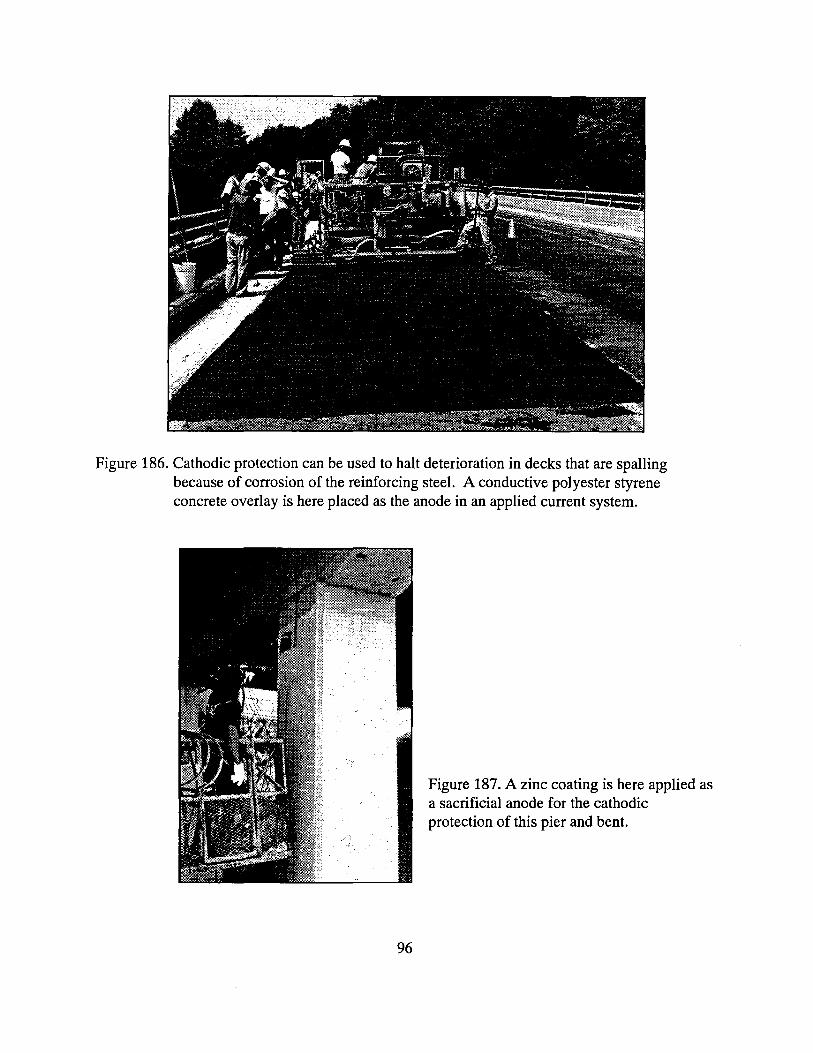
Figure 186. Cathodic protection can be used to halt deterioration in decks that are spalling because of corrosion of the reinforcing steel. A conductive polyester styrene concrete overlay is here placed as the anode in an applied current system.
Figure 187. A zinc coating is here applied as
a sacrificial anode for the cathodic protection of this pier and bent.
96

Figure 188. A conductive coating is here applied to the underside of a pier bent to provide applied current cathodic protection.
Figure 189. A conductive coating has been applied to the piers and bent to provide applied current cathodic protection.
97

Criteria for Good Repair and Protection Systems Proper design
Good surface preparation
Quality mixture proportions
Proper placement (adequate consolidation)
Good cure
Figure 190. Criteria for good repair and protection systems.
98
Related Documents