9-40691 1 02/12/2004 REPAIR MANUAL CX225SR

Welcome message from author
This document is posted to help you gain knowledge. Please leave a comment to let me know what you think about it! Share it to your friends and learn new things together.
Transcript
9-40691 1 02/12/2004
REPAIR MANUAL
CX225SR

Contents
9-40691 1 02/12/2004
INTRODUCTION DISTRIBUTION SYSTEMS A POWER PRODUCTION B TRAVELLING D BODY AND STRUCTURE E FRAME POSITIONING F WORKING ARM H TOOLS AND COUPLERS J
9-40691 1 02/12/2004 1
INTRODUCTION
Contents
9-40691 1 02/12/2004 2
INTRODUCTION
Foreword ( - A.10.A.40) 3 CX225SR
Safety rules ( - A.50.A.10) 4 CX225SR
Basic instructions ( - A.90.A.05) 6 CX225SR
Torque ( - A.90.A.10) 7 CX225SR
Torque ( - A.90.A.10) 8 CX225SR
Dimension ( - A.92.A.30) 11 CX225SR
Weight ( - A.92.A.40) 12 CX225SR
Consumables ( - A.92.A.55) 13 CX225SR
Hydraulic contamination ( - A.92.A.60) 16 CX225SR
- A.80.A.10) 18 CX225SR WE
- A.80.A.10) 19 CX225SR NA
9-40691 1 02/12/2004 3
INTRODUCTION
Foreword ( - A.10.A.40) CX225SR
INTRODUCTION TO THE REPAIR MANUAL
This manual has been designed so that in the near future it can be made available on CD and in a database via a computer network. This will allow fast and targeted search and navigation between the various information modules.
Information search
CRIL03J033E01 1
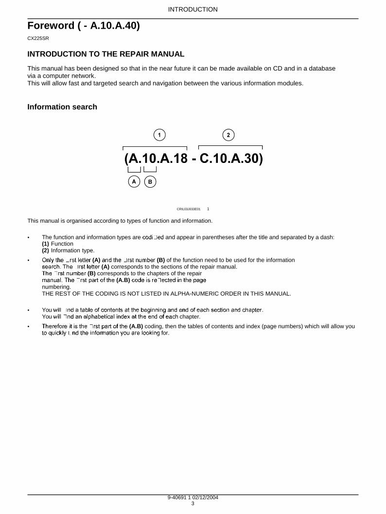
This manual is organised according to types of function and information.
• The function and information types are and appear in parentheses after the title and separated by a dash:
(1) Function (2) Information type.
• (A) (B) of the function need to be used for the information (A) corresponds to the sections of the repair manual.
(B) corresponds to the chapters of the repair (A.B)
numbering. THE REST OF THE CODING IS NOT LISTED IN ALPHA-NUMERIC ORDER IN THIS MANUAL.
• You
You chapter.
• (A.B) coding, then the tables of contents and index (page numbers) which will allow you for.
9-40691 1 02/12/2004 4
INTRODUCTION
Safety rules ( - A.50.A.10) CX225SR
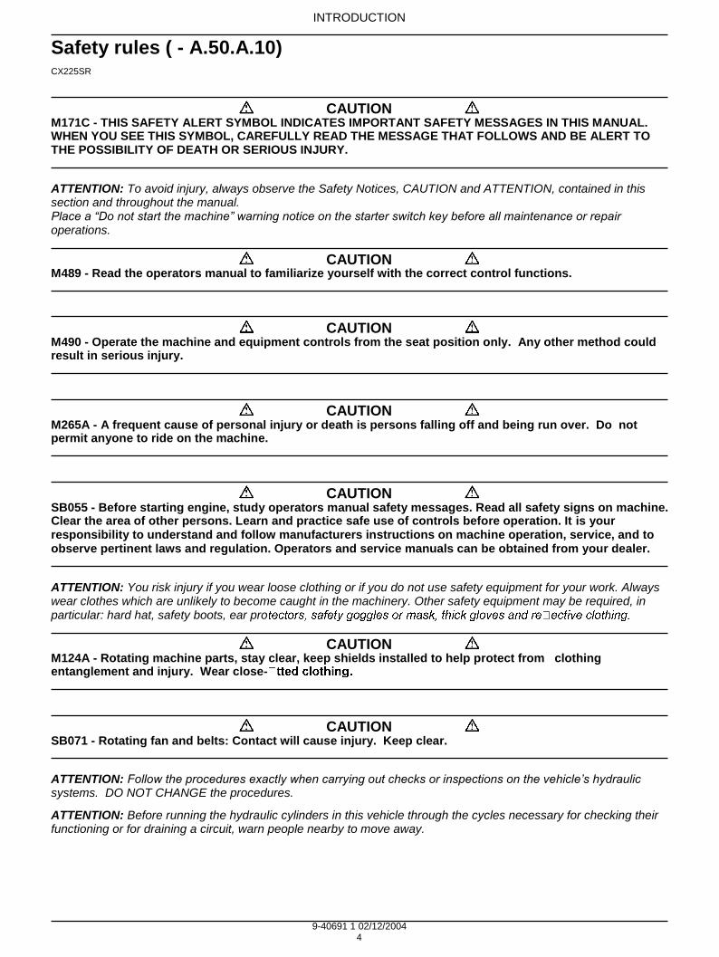
M171C - THIS SAFETY ALERT SYMBOL INDICATES IMPORTANT SAFETY MESSAGES IN THIS MANUAL. WHEN YOU SEE THIS SYMBOL, CAREFULLY READ THE MESSAGE THAT FOLLOWS AND BE ALERT TO THE POSSIBILITY OF DEATH OR SERIOUS INJURY.
ATTENTION: To avoid injury, always observe the Safety Notices, CAUTION and ATTENTION, contained in this section and throughout the manual. Place a “Do not start the machine” warning notice on the starter switch key before all maintenance or repair operations.
M489 - Read the operators manual to familiarize yourself with the correct control functions.
M490 - Operate the machine and equipment controls from the seat position only. Any other method could result in serious injury.
M265A - A frequent cause of personal injury or death is persons falling off and being run over. Do not permit anyone to ride on the machine.
SB055 - Before starting engine, study operators manual safety messages. Read all safety signs on machine. Clear the area of other persons. Learn and practice safe use of controls before operation. It is your responsibility to understand and follow manufacturers instructions on machine operation, service, and to observe pertinent laws and regulation. Operators and service manuals can be obtained from your dealer.
ATTENTION: You risk injury if you wear loose clothing or if you do not use safety equipment for your work. Always wear clothes which are unlikely to become caught in the machinery. Other safety equipment may be required, in particular: hard hat, safety boots, ear pro
M124A - Rotating machine parts, stay clear, keep shields installed to help protect from clothing entanglement and injury. Wear close-
SB071 - Rotating fan and belts: Contact will cause injury. Keep clear.
ATTENTION: Follow the procedures exactly when carrying out checks or inspections on the vehicle’s hydraulic systems. DO NOT CHANGE the procedures.
ATTENTION: Before running the hydraulic cylinders in this vehicle through the cycles necessary for checking their functioning or for draining a circuit, warn people nearby to move away.
CAUTION
CAUTION
CAUTION
CAUTION
CAUTION
CAUTION
CAUTION
9-40691 1 02/12/2004 5
INTRODUCTION
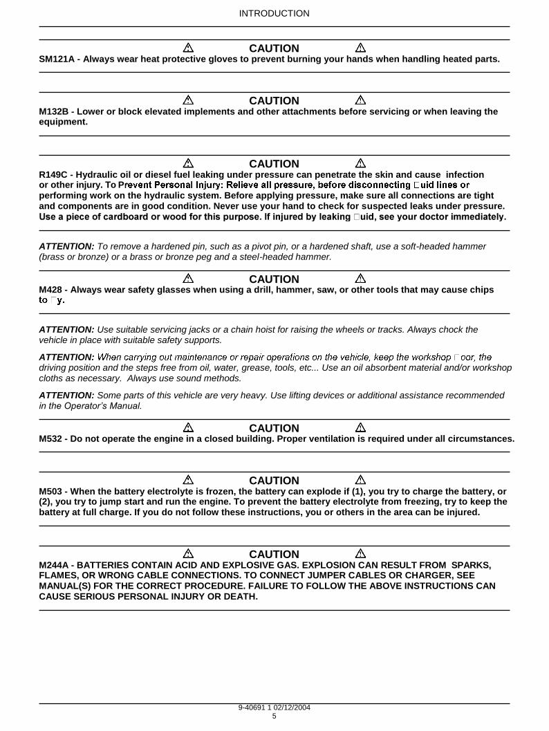
SM121A - Always wear heat protective gloves to prevent burning your hands when handling heated parts.
M132B - Lower or block elevated implements and other attachments before servicing or when leaving the equipment.
R149C - Hydraulic oil or diesel fuel leaking under pressure can penetrate the skin and cause infection or other injury. To Pperforming work on the hydraulic system. Before applying pressure, make sure all connections are tight and components are in good condition. Never use your hand to check for suspected leaks under pressure.
ATTENTION: To remove a hardened pin, such as a pivot pin, or a hardened shaft, use a soft-headed hammer (brass or bronze) or a brass or bronze peg and a steel-headed hammer.
M428 - Always wear safety glasses when using a drill, hammer, saw, or other tools that may cause chips
ATTENTION: Use suitable servicing jacks or a chain hoist for raising the wheels or tracks. Always chock the vehicle in place with suitable safety supports.
ATTENTION: driving position and the steps free from oil, water, grease, tools, etc... Use an oil absorbent material and/or workshop cloths as necessary. Always use sound methods.
ATTENTION: Some parts of this vehicle are very heavy. Use lifting devices or additional assistance recommended in the Operator’s Manual.
M532 - Do not operate the engine in a closed building. Proper ventilation is required under all circumstances.
M503 - When the battery electrolyte is frozen, the battery can explode if (1), you try to charge the battery, or (2), you try to jump start and run the engine. To prevent the battery electrolyte from freezing, try to keep the battery at full charge. If you do not follow these instructions, you or others in the area can be injured.
M244A - BATTERIES CONTAIN ACID AND EXPLOSIVE GAS. EXPLOSION CAN RESULT FROM SPARKS, FLAMES, OR WRONG CABLE CONNECTIONS. TO CONNECT JUMPER CABLES OR CHARGER, SEE MANUAL(S) FOR THE CORRECT PROCEDURE. FAILURE TO FOLLOW THE ABOVE INSTRUCTIONS CAN CAUSE SERIOUS PERSONAL INJURY OR DEATH.
CAUTION
CAUTION
CAUTION
CAUTION
CAUTION
CAUTION
CAUTION

9-40691 1 02/12/2004 6
INTRODUCTION
Basic instructions ( - A.90.A.05) CX225SR
GENERAL
Cleaning
Clean all metal parts except the bearings with white spirit or steam. Do not use caustic soda for steam cleaning. After each cleaning, dry and oil all parts. Clean the oil ducts with compressed air. Clean the bearings with
y and lubricate them.
Inspection
scratches and grooves can be removed with an oil stone or with a cloth dipped in red oxide. A complete visual inspection is necessary to detect wear and pitting, and replacing parts as soon as it becomes necessary will help to avoid premature breakdowns.
Bearings
Check that the bearings turn freely. Replace them if their adjustment is too free or if their functioning is irregular.
DO NOT DRY THE BEARINGS WITH COMPRESSED AIR.
Needle bearings
Before pushing needle bearings into a cylinder bore, always remove all metallic projections from the bore and its edges. Before pushing in bearings with a press, coat the inside and edges of the bearings with Vaseline.
Gears
Check all the gears and ensure that they do not show any signs of wear or damage. Replace the worn out or damaged gears.
Gaskets, O-
Always install new gaskets, O- -rings with Vaseline.
Shaft
Check all shafts showing wear or damage. Enusre that the surface of a shaft carrying a bearing or gasket is not damaged.
Spare parts
Always use CASE spare parts. To order these, refer to the Spare Parts Catalogue and indicate the correct reference number of the CASE spare parts. Breakdowns caused by the use of parts other than CASE spare parts are not covered by the warranty.
Lubrication

9-40691 1 02/12/2004 7
INTRODUCTION
Torque ( - A.90.A.10) CX225SR
STANDARD TIGHTENING TORQUE
Order of tightening nuts and cap screws.
a white residue on the thread after removal), must be cleaned with a thin oil or a suitable solvent, then dried.
CRIL03H012E01 1
The numbers in the diagrams represent the order of tightening.
Tightening torque
Where there are no special instructions, tighten cap nuts screws to the torques given in the table below.
Standard torque setting table.
Designation of cap screws (dimensions)
M6 M8 M10 M12 M14 M16 M18 M20
Cap screw Spanner in mm 10 13 17 19 22 24 27 30
Torque setting in Nm
6.9 19.6 39.2 58.8 98.1 157.2 196 274
Socket head screw
Wrench in mm 5 6 8 10 12 14 14 17
Torque setting in Nm
8.8 21.6 42.1 78.4 117.6 176.4 245 343
9-40691 1 02/12/2004 8
INTRODUCTION
Torque ( - A.90.A.10) CX225SR
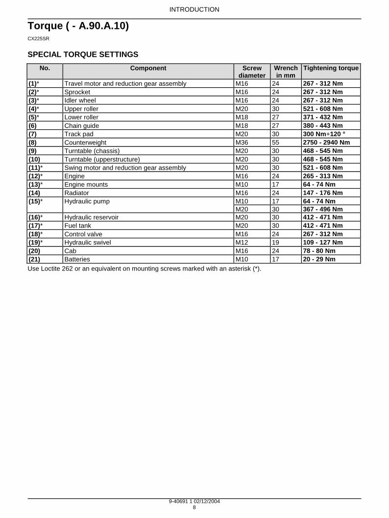
SPECIAL TORQUE SETTINGS
No. Component Screw diameter
Wrench in mm
Tightening torque
(1)* Travel motor and reduction gear assembly M16 24 267 - 312 Nm
(2)* Sprocket M16 24 267 - 312 Nm
(3)* Idler wheel M16 24 267 - 312 Nm
(4)* Upper roller M20 30 521 - 608 Nm
(5)* Lower roller M18 27 371 - 432 Nm
(6) Chain guide M18 27 380 - 443 Nm
(7) Track pad M20 30 300 Nm+120 °
(8) Counterweight M36 55 2750 - 2940 Nm
(9) Turntable (chassis) M20 30 468 - 545 Nm
(10) Turntable (upperstructure) M20 30 468 - 545 Nm
(11)* Swing motor and reduction gear assembly M20 30 521 - 608 Nm
(12)* Engine M16 24 265 - 313 Nm
(13)* Engine mounts M10 17 64 - 74 Nm
(14) Radiator M16 24 147 - 176 Nm
(15)* Hydraulic pump M10 17 64 - 74 Nm
M20 30 367 - 496 Nm
(16)* Hydraulic reservoir M20 30 412 - 471 Nm
(17)* Fuel tank M20 30 412 - 471 Nm
(18)* Control valve M16 24 267 - 312 Nm
(19)* Hydraulic swivel M12 19 109 - 127 Nm
(20) Cab M16 24 78 - 80 Nm
(21) Batteries M10 17 20 - 29 Nm
Use Loctite 262 or an equivalent on mounting screws marked with an asterisk (*).
Contents
DISTRIBUTION SYSTEMS - A
PRIMARY HYDRAULIC POWER SYSTEM CX225SR
HYDRAULIC COMMAND SYSTEM CX225SR
ELECTRICAL POWER SYSTEM CX225SR
LIGHTING SYSTEM CX225SR
A.10.A
A.14.A
A.30.A
A.40.A
26019 1 02/12/2004 A


26020 1 02/12/2004 A.10.A / 1
DISTRIBUTION SYSTEMS - A
PRIMARY HYDRAULIC POWER SYSTEM - 10.A
CX225SR
INTRODUCTION
26020 1 02/12/2004 A.10.A / 2
DISTRIBUTION SYSTEMS - A
PRIMARY HYDRAULIC POWER SYSTEM - 10.A
TECHNICAL DATA PRIMARY HYDRAULIC POWER SYSTEM - - D.40.A.10) 5
CX225SR
PRIMARY HYDRAULIC POWER SYSTEM - - D.40.A.10) 7 CX225SR
PRIMARY HYDRAULIC POWER SYSTEM - Special tools (A.10.A - D.20.A.40) 9 CX225SR WE
PRIMARY HYDRAULIC POWER SYSTEM - Special tools (A.10.A - D.20.A.40) 11 CX225SR NA
PRIMARY HYDRAULIC POWER SYSTEM - Seed rates (A.10.A - D.50.A.60) 13 CX225SR
Hydraulic pump Hydraulic pump - Special tools (A.10.A.20 - D.20.A.40) 15
CX225SR
Hydraulic pump - Service limits (A.10.A.20 - D.20.A.20) 18 CX225SR
FUNCTIONAL DATA PRIMARY HYDRAULIC POWER SYSTEM - Static description (A.10.A - C.30.A.20) 19
CX225SR
PRIMARY HYDRAULIC POWER SYSTEM - Dynamic description (A.10.A - C.30.A.10) 20 CX225SR
Stack valve Stack valve - External view (A.10.A.18 - C.10.A.40) 23
CX225SR
Stack valve - Sectional view (A.10.A.18 - C.10.A.30) 26 CX225SR
Stack valve Inlet section - Sectional view (A.10.A.18.10 - C.10.A.30) 31 CX225SR
Stack valve Outlet section - Sectional view (A.10.A.18.20 - C.10.A.30) 32 CX225SR
Hydraulic pump Hydraulic pump - Sectional view (A.10.A.20 - C.10.A.30) 33
CX225SR
Compensator Compensator - Sectional view (A.10.A.23 - C.10.A.30) 37
CX225SR
Sensing system Sensing system Temperature sensor - Electronic schema (A.10.A.95.90 - C.20.A.50) 38
CX225SR
Powerboost system

26020 1 02/12/2004 A.10.A / 3
Contents
Powerboost system - Electronic schema (A.10.A.10 - C.20.A.50) 39 CX225SR
SERVICE PRIMARY HYDRAULIC POWER SYSTEM - Warm up (A.10.A - F.35.A.40) 40
CX225SR
PRIMARY HYDRAULIC POWER SYSTEM - Depressurising (A.10.A - F.35.A.51) 41 CX225SR
PRIMARY HYDRAULIC POWER SYSTEM - - F.35.A.20) 42 CX225SR
PRIMARY HYDRAULIC POWER SYSTEM - Bleed (A.10.A - F.35.A.25) 43 CX225SR
PRIMARY HYDRAULIC POWER SYSTEM - Pressure test (A.10.A - F.40.A.30) 44 CX225SR
PRIMARY HYDRAULIC POWER SYSTEM - Decontaminating (A.10.A - F.30.A.60) 46 CX225SR
Stack valve Stack valve - Remove (A.10.A.18 - F.10.A.10) 48
CX225SR
Stack valve - Overhaul (A.10.A.18 - F.10.A.40) 49 CX225SR
Stack valve Outlet section - Disassemble (A.10.A.18.20 - F.10.A.25) 50 CX225SR
Stack valve Inlet section - Disassemble (A.10.A.18.10 - F.10.A.25) 51 CX225SR
Stack valve - Visual inspection (A.10.A.18 - F.40.A.10) 52 CX225SR
Stack valve Inlet section - Assemble (A.10.A.18.10 - F.10.A.20) 53 CX225SR
Stack valve Outlet section - Assemble (A.10.A.18.20 - F.10.A.20) 54 CX225SR
Stack valve - Install (A.10.A.18 - F.10.A.15) 55 CX225SR
Relief valve Relief valve - Disassemble (A.10.A.16 - F.10.A.25) 56
CX225SR
Relief valve - Assemble (A.10.A.16 - F.10.A.20) 57 CX225SR
Relief valve - Pressure test (A.10.A.16 - F.40.A.30) 58 CX225SR
Relief valve - Pressure setting (A.10.A.16 - F.45.A.70) 59 CX225SR
Powerboost system Powerboost system Electrovalve - Electrical test (A.10.A.10.15 - F.40.A.50) 60
CX225SR
Hydraulic pump Hydraulic pump - Remove (A.10.A.20 - F.10.A.10) 61
CX225SR
Hydraulic pump - Disassemble (A.10.A.20 - F.10.A.25) 63 CX225SR
Hydraulic pump - Assemble (A.10.A.20 - F.10.A.20) 70 CX225SR

26020 1 02/12/2004 A.10.A / 4
Hydraulic pump - Install (A.10.A.20 - F.10.A.15) 80 CX225SR
Hydraulic pump - Bleed (A.10.A.20 - F.35.A.25) 82 CX225SR
Hydraulic pump - Pressure test (A.10.A.20 - F.40.A.30) 83 CX225SR
Reservoir Reservoir - Remove (A.10.A.22 - F.10.A.10) 84
CX225SR
Reservoir - Install (A.10.A.22 - F.10.A.15) 85 CX225SR
Compensator Compensator - Disassemble (A.10.A.23 - F.10.A.25) 86
CX225SR
Compensator - Assemble (A.10.A.23 - F.10.A.20) 87 CX225SR
- Remove (A.10.A.24 - F.10.A.10) 89
CX225SR
- Install (A.10.A.24 - F.10.A.15) 90 CX225SR
Sensing system Sensing system Temperature sensor - Electrical test (A.10.A.95.90 - F.40.A.50) 91
CX225SR
DIAGNOSTIC PRIMARY HYDRAULIC POWER SYSTEM - Troubleshooting (A.10.A - G.40.A.10) 92
CX225SR
Stack valve Stack valve - Troubleshooting (A.10.A.18 - G.40.A.10) 92
CX225SR
Relief valve Relief valve - Troubleshooting (A.10.A.16 - G.40.A.10) 93
CX225SR

26020 1 02/12/2004 A.10.A / 5
Contents
>> BUY NOW download online
Manual
Related Documents


