ESSENTIAL TECHNICAL DATA ON STEEL REINFORCEMENT R E I N V E N T I N G R E I N F O R C I N G w w w . r e i n f o r c i n g . c o m w w w . r e i n f o r c i n g . t v 4.0 Build with OneSteel Reinforcing

Welcome message from author
This document is posted to help you gain knowledge. Please leave a comment to let me know what you think about it! Share it to your friends and learn new things together.
Transcript
EssEntial tEchnical Data on stEEl REinfoRcEmEntRE
INVENTING
R
EINFORCIN
G
www.reinforcing.co
m
www.re
inforcing. tv
4.0
Build with OneSteel Reinforcing
2about onesteel Reinforcing
Reinventing reinforcing with innovative construction and mining solutions
500PlUs® REBaR – The first high strength reinforcing bar
500PlUs® BamtEc® – The world’s fastest steelfixing system
500PlUs® RomtEch® – An innovative tunnel support system of rebar girders
500PlUs® PREfaB – Our wide range of off-site prefabricated elements
Eco-REo™ – Economical and environmental REBAR, REOMESH® & Decking products
onEslaB® – Our complete supply package for detached house slabs
onEmEsh® – Wide range of square, rectangular and trench meshes
UtEmEsh® – Compact, easy to carry mesh for driveways, paths and patios
tRUssDEK® – Long span composite suspended floor system
minEmEsh™ – Tailored roof support system for coal & metalliferous mines
OneSteel Reinforcing is Australia’s premier supplier of steel reinforcing solutions for commercial, residential and civil construction as well as rural, industrial and mining.
A national branch and distributor network services customers Australia wide by supplying quality steel reinforcing products to Australia’s largest construction companies through to the home renovator.
OneSteel Reinforcing has ACRS third party certified world-class manufacturing and provides innovative engineered reinforcing solutions to reduce labour needs and streamline construction.
We started as Aquila Steel in 1928 so we have a long history. Along the way we have incorporated other leading reinforcing businesses such as Boral Steel, Queensland Welded Mesh, Marner Steel & Mesh, and BHP Reinforcing Products. In the year 2000 we became OneSteel Reinforcing.

3
www.reinforcing.com | www.reinforcing.tv 3
Along with REODATA, we also have a range of reinforcing essentials, guides and resources that will benefit your next project including:
REoWoRKs – comprehensive CD and DVD combination for everything on REO including case studies, videos and technical data.
REo calcUlatoR – for steel reinforcement area calculations.
REo WiRE GaUGE – for measuring REOMESH® wire diameters.
REo BaR GaUGE – for measuring REBAR diameters.
national PRoDUct & sERVicEs cataloGUE – the most comprehensive guide to reinforcing available anywhere today.
REinfoRcinG.com – the online resource for products, technical data, case studies and testimonials that’s right at your fingertips.
REinfoRcinG.tV – our YouTube™ channel where you can see our products and services in action and listen to our customers talking about the benefits they get from using our reinforcing solutions.
to keep you up to date on all our reinforcing products, visit the ‘Register for Updates’ page at www.reinforcing.com
4contents
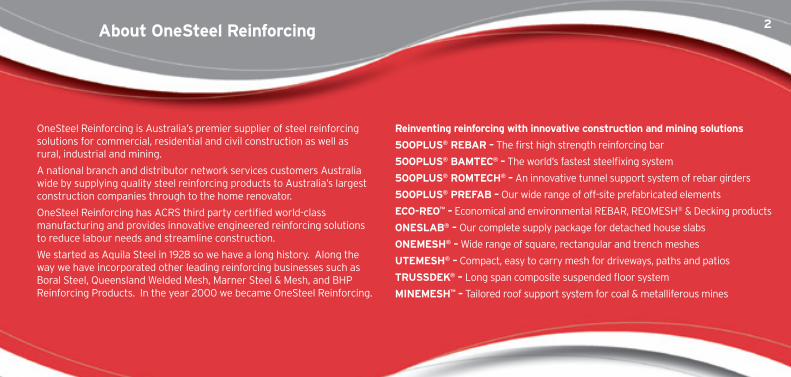
ECO-REO™ - Sustainable Reinforcing Products 6
OneSteel Reinforcing and Green Star® Steel Credit Points 10
OneSteel Reinforcing can meet the new Green Star®
steel credit requirements 11
Green Building Council documentation requirements 11
REBAR & REO WIRE Product Designations 12
500PLUS® REBAR Stock Lengths & Approximate Lengths per Tonne 13
500PLUS® REBAR Identification Markings 14
500PLUS® REBAR Detailing Information 16
Stress Development & Lap Splicing of Straight Deformed Bars in Tension 18
Positioning Tolerances for Reinforcement to AS 3600 : 2009 28
Calculating Reinforcing & Accessory Quantities 29
500PLUS® REBAR Standard Hooks and Cogs 30
Minimum Dimensions for Standard Shapes Processed to AS 3600 : 2009 32
Processing 500PLUS® REBAR to AS 3600 : 2009 34
Processing 500PLUS® REBAR and Wire to AS 3600 : 2009 35
Bending & Rebending 500PLUS® REBAR 36
Heating & Welding 500PLUS® REBAR 38
Threading 500PLUS® REBAR 39
500PLUS® REIDBAR™ 40
500PLUS® PREFAB 41
500PLUS® BAMTEC® Reinforcing Carpets 42
TRUSSDEK® Long Span Structural Decking 44
5
www.reinforcing.com | www.reinforcing.tv 5
500PLUS® ROMTECH® Tunnel Girders 46
POOLSTEEL® 47
ONEMESH® Square & Rectangular 48
ONEMESH® Trench Mesh 49
Lapped Splices for ONEMESH® Mesh in Tension or Compression 50
ONEMESH® Identification Markings 51
Footing Cages 52
UTEMESH® 53
HANDIMESH® General Purpose Mesh 54
IRONBARK® Rural Mesh 55
Accessories - Concrete & Building 56
BLOCKAID© 58
Reinforced Concrete Thesaurus 59
Imperial to Metric Units Conversion Table 64
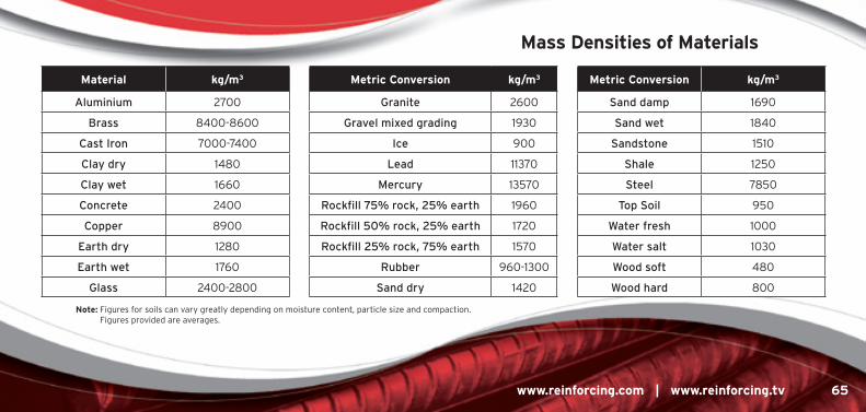
Mass Densities of Materials 65
Basic Support Reaction, Bending Moment & Deflection Formulae 66
Steel Reinforcement Standards & Relevant Concrete Construction Standards 67
OneSteel Reinforcing REOMESH® & REBAR are ACRS accredited 72
Steel Reinforcement Institute of Australia (SRIA) Technical Notes 73
OneSteel Reinforcing Branch Locations 74
6
OneSteel Reinforcing has introduced a selected range of REBAR, REOMESH® and Decking products.
These are products that can provide a more sustainable use of materials in structures.
These carry the additional branding of Eco-REo™, Eco-BaR™ or Eco-mEsh™, as they can provide economic and environmental benefits compared to traditional reinforcing steels.
* Economical – The products can give more cost-efficient cover and economy in the number of sheets or bars, or the volume of steel needed to efficiently reinforce the structure and meet the design intent of the project.
* EnViRonmEntal – OneSteel’s manufacturing of reinforcing steel utilises energy reducing Polymer Injection Technology (PIT) and recycled steel scrap content.
* Supporting information on environmental claims for specific OneSteel Reinforcing ECO-REO™ products is available on the ‘Technical Resources’ page of the OneSteel Reinforcing website www.reinforcing.com
Eco-REo™ - sustainableReinforcing Products
If customers talk to OneSteel Reinforcing in the early stages of the project we can suggest ways of redesigning the reinforcing such as spacing and diameters to optimise material use.
7
www.reinforcing.com | www.reinforcing.tv 7
Eco-BaR™ products include:• 500PlUs® BamtEc® – Engineered reinforcing bar carpets can allow
the size and positioning of reinforcing steel to be optimised with variable bar diameters, spacings and lengths.
• 500PlUs® PREfaB – Prefabricated reinforcement can be produced more efficiently in the factory than on site, enabling reduced labour and time, and also generating less waste and scrap.
PREFAB
8Eco-REo™ - sustainableReinforcing Products
Eco-mEsh™ products include onEmEsh® maDE-to-siZE and UtEmEsh®
• Customised special run ONEMESH® can minimise duplication of reinforcing steel that results from excess lapping and scrap losses due to trimming of mesh sheets.
• Engineered and tailored mesh solutions can include variable wire spacing, diameters and ductilities, and optimised mesh size (length and width).
• Examples are the new UTEMESH® and the extra large (up to 9 m x 3 m) ONEMESH® MADE-TO-SIZE sheets which can give more cost-efficient solutions by reducing the number of sheets used on projects.
made to size
9
www.reinforcing.com | www.reinforcing.tv 9
Eco-REo™ products include tRUssDEK®
• Like reinforcing bar carpets and special meshes, TRUSSDEK® panels can reduce lapping and steel intensity and also serves as a permanent formwork system, thereby eliminating other formwork and the need for backpropping.
• Spacing between TRUSSDEK® panels can be optimised to reduce material, and concrete savings due to voiding of TRUSSDEK® panels can be significant.
• The volume of the steel reinforcing bars or mesh in a TRUSSDEK® slab can be up to 60% of that used in a conventional one-way reinforced-concrete slab.
• TRUSSDEK® panels can span up to 8.0 metres, which in steelframed buildings can potentially lead to the complete elimination of the secondary steel beams.
TRUSSDEK
10
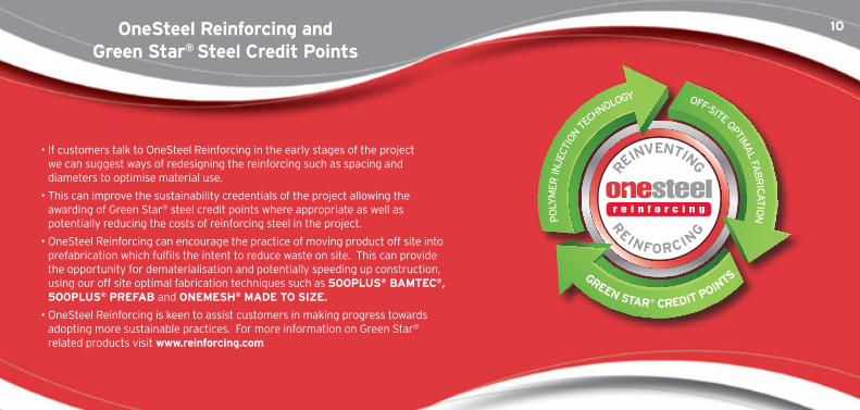
• If customers talk to OneSteel Reinforcing in the early stages of the project we can suggest ways of redesigning the reinforcing such as spacing and diameters to optimise material use.
• This can improve the sustainability credentials of the project allowing the awarding of Green Star® steel credit points where appropriate as well as potentially reducing the costs of reinforcing steel in the project.
• OneSteel Reinforcing can encourage the practice of moving product off site into prefabrication which fulfils the intent to reduce waste on site. This can provide the opportunity for dematerialisation and potentially speeding up construction, using our off site optimal fabrication techniques such as 500PlUs® BamtEc®, 500PlUs® PREfaB and onEmEsh® maDE to siZE.
• OneSteel Reinforcing is keen to assist customers in making progress towards adopting more sustainable practices. For more information on Green Star® related products visit www.reinforcing.com
REINVENTING
REINFORCIN
G
PO
LYM
ER IN
JECT
ION T
ECHNOLOGY
GREEN STAR® CREDIT POINTS
OFF-SITE OPTIMA
L FAB
RIC
AT
ION
onesteel Reinforcing and Green star® steel credit Points
11
www.reinforcing.com | www.reinforcing.tv 11
• OneSteel has a valid 14001 Environmental Management System in place.
• OneSteel is a member of the World Steel Association’s Climate Action Programme.
• At least 60% of OneSteel Reinforcing steel is produced using Polymer Injection Technology – an energy reducing process in manufacturing.
• At least 95% of all OneSteel Reinforcing rebar and reomesh meets or exceeds 500 MPa strength grade.
• At least 15% by mass of all OneSteel Reinforcing REBAR and REOMESH® can be produced using off site optimal fabrication techniques for agreed projects.
• Documentation to demonstrate compliance with optimal fabrication techniques is required from the steel fabricator/reinforcement processor in the form of a short report on where optimal steel manufacturing techniques are claimed, the optimal off site fabrication techniques used in the building, and the quantities (by mass) of steel used in each optimal off site fabrication technique.
• onesteel Reinforcing can confirm pre-project by letter that it can meet the requirements, and will also complete the post-project GBca criteria 3 & 4 charts required for the project.
for more information on GBca documentation visit www.gbca.com.au
onesteel Reinforcing can meet the new Green star® steel credit requirements
Green Building council documentation requirements
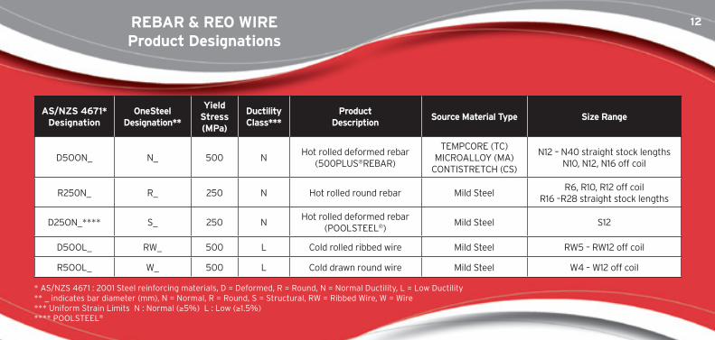
12REBaR & REo WiRE Product Designations
as/nZs 4671*Designation
onesteel Designation**
Yield stress (mPa)
Ductility class***
Product Description
source material type size Range
D5OON_ N_ 500 NHot rolled deformed rebar
(500PLUS®REBAR)
TEMPCORE (TC)MICROALLOY (MA)
CONTISTRETCH (CS)
N12 – N40 straight stock lengthsN10, N12, N16 off coil
R250N_ R_ 250 N Hot rolled round rebar Mild SteelR6, R10, R12 off coil
R16 –R28 straight stock lengths
D25ON_**** S_ 250 NHot rolled deformed rebar
(POOLSTEEL®)Mild Steel S12
D5OOL_ RW_ 500 L Cold rolled ribbed wire Mild Steel RW5 – RW12 off coil
R5OOL_ W_ 500 L Cold drawn round wire Mild Steel W4 – W12 off coil
* AS/NZS 4671 : 2001 Steel reinforcing materials, D = Deformed, R = Round, N = Normal Ductility, L = Low Ductility ** _ indicates bar diameter (mm), N = Normal, R = Round, S = Structural, RW = Ribbed Wire, W = Wire *** Uniform Strain Limits N : Normal (≥5%) L : Low (≥1.5%) **** POOLSTEEL®
13
www.reinforcing.com | www.reinforcing.tv 13
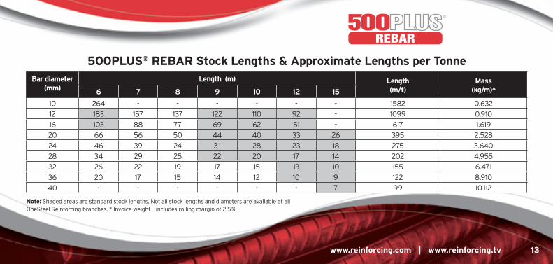
500PlUs® REBaR stock lengths & approximate lengths per tonne
REBAR
Bar diameter (mm)
length (m) length (m/t)
mass (kg/m)*6 7 8 9 10 12 15
10 264 - - - - - - 1582 0.632
12 183 157 137 122 110 92 - 1099 0.910
16 103 88 77 69 62 51 - 617 1.619
20 66 56 50 44 40 33 26 395 2.528
24 46 39 24 31 28 23 18 275 3.640
28 34 29 25 22 20 17 14 202 4.955
32 26 22 19 17 15 13 10 155 6.471
36 20 17 15 14 12 10 9 122 8.910
40 - - - - - - 7 99 10.112
note: Shaded areas are standard stock lengths. Not all stock lengths and diameters are available at all OneSteel Reinforcing branches. * Invoice weight – includes rolling margin of 2.5%
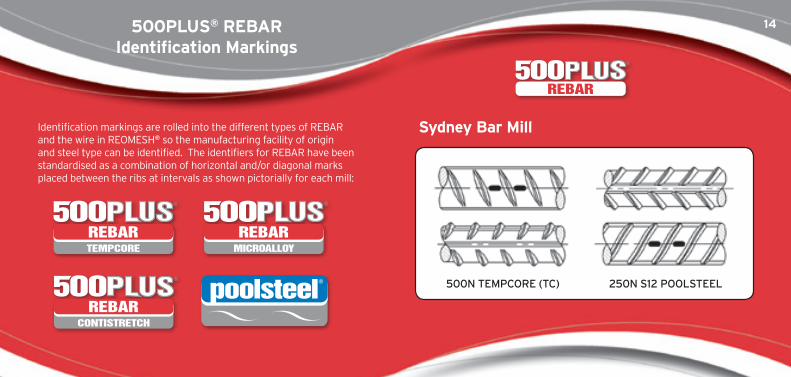
14500PlUs® REBaR identification markings
TEMPCORE
REBARMICROALLOY
REBAR
CONTISTRETCH
REBAR
Identification markings are rolled into the different types of REBAR and the wire in REOMESH® so the manufacturing facility of origin and steel type can be identified. The identifiers for REBAR have been standardised as a combination of horizontal and/or diagonal marks placed between the ribs at intervals as shown pictorially for each mill:
sydney Bar mill
500N TEMPCORE (TC) 250N S12 POOLSTEEL
REBAR
15
www.reinforcing.com | www.reinforcing.tv 15
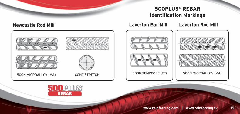
newcastle Rod mill
500N MICROALLOY (MA) CONTISTRETCH
laverton Bar mill laverton Rod mill
500N TEMPCORE (TC) 500N MICROALLOY (MA)
500PlUs® REBaR identification markings
REBAR
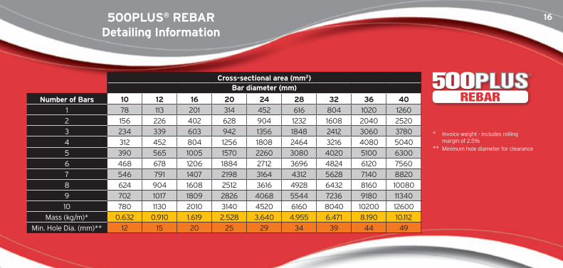
16500PlUs® REBaRDetailing information
cross-sectional area (mm2)Bar diameter (mm)
number of Bars 10 12 16 20 24 28 32 36 40
1 78 113 201 314 452 616 804 1020 1260
2 156 226 402 628 904 1232 1608 2040 2520
3 234 339 603 942 1356 1848 2412 3060 3780
4 312 452 804 1256 1808 2464 3216 4080 5040
5 390 565 1005 1570 2260 3080 4020 5100 6300
6 468 678 1206 1884 2712 3696 4824 6120 7560
7 546 791 1407 2198 3164 4312 5628 7140 8820
8 624 904 1608 2512 3616 4928 6432 8160 10080
9 702 1017 1809 2826 4068 5544 7236 9180 11340
10 780 1130 2010 3140 4520 6160 8040 10200 12600
Mass (kg/m)* 0.632 0.910 1.619 2.528 3.640 4.955 6.471 8.190 10.112
Min. Hole Dia. (mm)** 12 15 20 25 29 34 39 44 49
* Invoice weight - includes rolling margin of 2.5%
** Minimum hole diameter for clearance
REBAR
17
www.reinforcing.com | www.reinforcing.tv 17
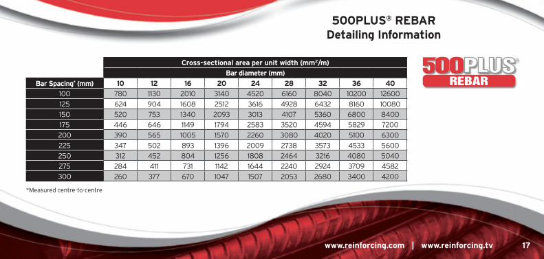
500PlUs® REBaRDetailing information
cross-sectional area per unit width (mm2/m)
Bar diameter (mm)
Bar spacing* (mm) 10 12 16 20 24 28 32 36 40
100 780 1130 2010 3140 4520 6160 8040 10200 12600
125 624 904 1608 2512 3616 4928 6432 8160 10080
150 520 753 1340 2093 3013 4107 5360 6800 8400
175 446 646 1149 1794 2583 3520 4594 5829 7200
200 390 565 1005 1570 2260 3080 4020 5100 6300
225 347 502 893 1396 2009 2738 3573 4533 5600
250 312 452 804 1256 1808 2464 3216 4080 5040
275 284 411 731 1142 1644 2240 2924 3709 4582
300 260 377 670 1047 1507 2053 2680 3400 4200
REBAR
*Measured centre-to-centre
18stress Development & lap splicing of straight Deformed Bars in tension
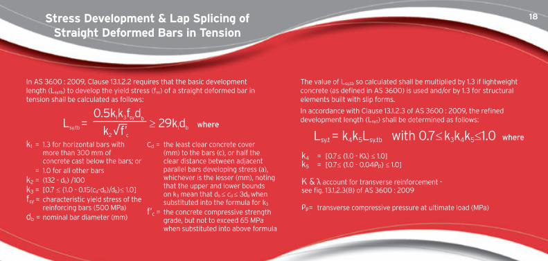
In AS 3600 : 2009, Clause 13.1.2.2 requires that the basic development length (Lsy.tb) to develop the yield stress (fsy) of a straight deformed bar in tension shall be calculated as follows:
The value of Lsy.tb so calculated shall be multiplied by 1.3 if lightweight concrete (as defined in AS 3600) is used and/or by 1.3 for structural elements built with slip forms.
In accordance with Clause 13.1.2.3 of AS 3600 : 2009, the refined development length (Lsy.t) shall be determined as follows:Lsy.tb =
0.5k1k3fsydb
≥ 29k1db where
k1 = 1.3 for horizontal bars with
more than 300 mm of concrete cast below the bars; or
= 1.0 for all other barsk2
= (132 - db) /100k3
= [0.7 ≤ {1.0 - 0.15(cd-db)/db}≤ 1.0]fsy
= characteristic yield stress of the reinforcing bars (500 MPa)
db = nominal bar diameter (mm)
cd = the least clear concrete cover
(mm) to the bars (c), or half the clear distance between adjacent parallel bars developing stress (a), whichever is the lesser (mm), noting that the upper and lower bounds on k3 mean that db ≤ cd ≤ 3db when substituted into the formula for k3
f’c = the concrete compressive strength grade, but not to exceed 65 MPa when substituted into above formula
Lsy.t = k4k5Lsy.tb with 0.7≤ k3k4k5≤1.0 where
k4 = [0.7≤ {1.0 - Kλ} ≤ 1.0]
k5 = [0.7≤ {1.0 - 0.04ρp} ≤ 1.0]
K & λ account for transverse reinforcement - see fig. 13.1.2.3(B) of AS 3600 : 2009
ρp = transverse compressive pressure at ultimate load (MPa)
k2 √f’c
19
www.reinforcing.com | www.reinforcing.tv 19
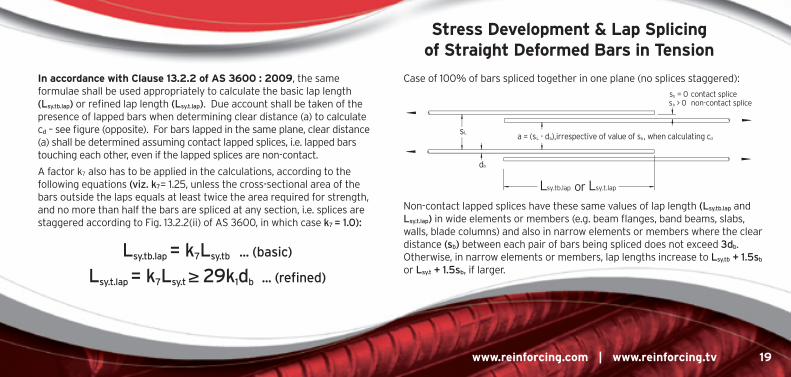
in accordance with clause 13.2.2 of as 3600 : 2009, the same formulae shall be used appropriately to calculate the basic lap length (Lsy.tb.lap) or refined lap length (Lsy.t.lap). Due account shall be taken of the presence of lapped bars when determining clear distance (a) to calculate cd – see figure (opposite). For bars lapped in the same plane, clear distance (a) shall be determined assuming contact lapped splices, i.e. lapped bars touching each other, even if the lapped splices are non-contact.
A factor k7 also has to be applied in the calculations, according to the following equations (viz. k7= 1.25, unless the cross-sectional area of the bars outside the laps equals at least twice the area required for strength, and no more than half the bars are spliced at any section, i.e. splices are staggered according to Fig. 13.2.2(ii) of AS 3600, in which case k7 = 1.0)::
Case of 100% of bars spliced together in one plane (no splices staggered):
Non-contact lapped splices have these same values of lap length (Lsy.tb.lap and Lsy.t.lap) in wide elements or members (e.g. beam flanges, band beams, slabs, walls, blade columns) and also in narrow elements or members where the clear distance (sb) between each pair of bars being spliced does not exceed 3db. Otherwise, in narrow elements or members, lap lengths increase to Lsy.tb + 1.5sb or Lsy.t + 1.5sb, if larger.
Lsy.tb.lap = k7Lsy.tb ... (basic)
Lsy.t.lap = k7Lsy.t ≥ 29k1db ... (refined)
stress Development & lap splicing of straight Deformed Bars in tension
20stress Development & lap splicing of straight Deformed Bars in tension
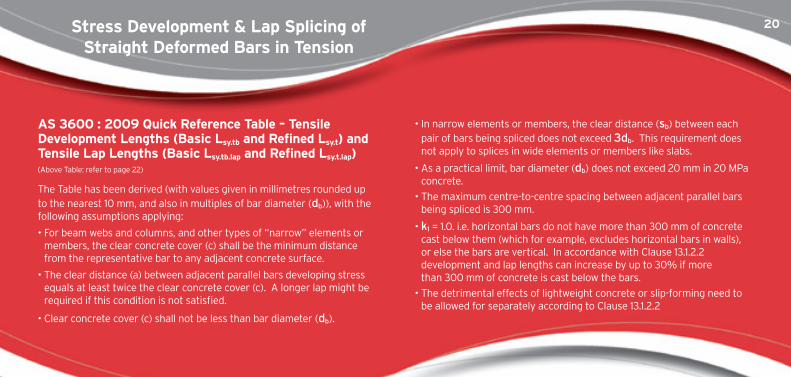
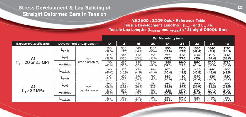
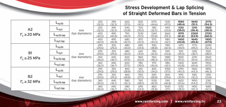
as 3600 : 2009 Quick Reference table – tensile Development lengths (Basic lsy.tb and Refined lsy.t) and tensile lap lengths (Basic lsy.tb.lap and Refined lsy.t.lap) (Above Table: refer to page 22)
The Table has been derived (with values given in millimetres rounded up to the nearest 10 mm, and also in multiples of bar diameter (db)), with the following assumptions applying:
• For beam webs and columns, and other types of “narrow” elements or members, the clear concrete cover (c) shall be the minimum distance from the representative bar to any adjacent concrete surface.
• The clear distance (a) between adjacent parallel bars developing stress equals at least twice the clear concrete cover (c). A longer lap might be required if this condition is not satisfied.
• Clear concrete cover (c) shall not be less than bar diameter (db).
• In narrow elements or members, the clear distance (sb) between each pair of bars being spliced does not exceed 3db. This requirement does not apply to splices in wide elements or members like slabs.
• As a practical limit, bar diameter (db) does not exceed 20 mm in 20 MPa concrete.
• The maximum centre-to-centre spacing between adjacent parallel bars being spliced is 300 mm.
• k1 = 1.0. i.e. horizontal bars do not have more than 300 mm of concrete cast below them (which for example, excludes horizontal bars in walls), or else the bars are vertical. In accordance with Clause 13.1.2.2 development and lap lengths can increase by up to 30% if more than 300 mm of concrete is cast below the bars.
• The detrimental effects of lightweight concrete or slip-forming need to be allowed for separately according to Clause 13.1.2.2
21
www.reinforcing.com | www.reinforcing.tv 21
Lap lengths have been calculated conservatively by ignoring any beneficial effects of possible staggering or lower bar stress levels, i.e. k7 has been assumed to equal 1.25.
The design solutions are presented in five groups according to the different combinations of minimum concrete cover (c) and concrete compressive strength grade (f’c) given in Table 4.10.3.2 of AS 3600 : 2009, for common Exposure Classifications A1, A2, B1 and B2, that apply when standard formwork and compaction are used.
For A1 or A2 Exposure Classification, for cases when bar diameter (db) exceeds the minimum allowable concrete cover (c) (according to Table 4.10.3.2), design solutions have been determined by assuming c = 25, 30, 35, 40 or 40 mm for db = 24, 28, 32, 36 or 40 mm respectively, and are shown in bold in the AS 3600 : 2009 Quick Reference Table.
The solutions represent the maximum development or lap length required for all possible combinations of c and f’c applicable to each particular group.
Refined development and lap lengths (Lsy.t and Lsy.t.lap) have been calculated assuming the product k3k4k5 = 0.7, i.e. the maximum possible benefit is provided by confinement from transverse reinforcement and/or pressure. It follows that, depending on the value of k3, 0.7 ≤ k4k5 ≤ 1.0.
It is left up to the designer to confirm that there is sufficient transverse reinforcement (accounted for by k4) and/or transverse pressure (accounted for by k5) to justify using a refined development or lap length if it is less than the corresponding basic development or lap length (Lsy.tb or Lsy.tb.lap).
Where reinforcing bars of different sizes are lapped together, the tensile lap length should equal the larger of the tensile lap length (Lsy.tb.lap or Lsy.t.lap) for the smaller diameter bar, or the tensile development length (Lsy.tb or Lsy.t) for the larger diameter bar.
stress Development & lap splicing of straight Deformed Bars in tension
22stress Development & lap splicing of straight Deformed Bars in tension
as 3600 : 2009 Quick Reference table tensile Development lengths – (lsy.tb and lsy.t) &
tensile lap lengths (lsy.tb.lap and lsy.t.lap) of straight D500n Bars
Bar Diameter db (mm)
Exposure classification Development or lap length 10 12 16 20 24 28 32 36 40
A1f’c = 20 or 25 MPa
Lsy.tb
mm (bar diameters)
390 (39.0)
500 (41.7)
740 (46.3)
1000 (50.0)
1100 (45.8)
1330 (47.5)
1580 (49.4)
1840 (51.1)
2170 (54.3)
Lsy.t320
(32.0)390
(32.5)540
(33.8)700
(35.0)770
(32.1)940
(33.6)1120 (35)
1310 (36.4)
1520 (38.0)
Lsy.tb.lap490
(49.0)630
(52.5)930
(58.1)1250
(62.5)1380 (57.5)
1660 (59.3)
1970 (61.6)
2300 (63.9)
2720 (68.0)
Lsy.t.lap400
(40.0)490
(40.8)670
(41.9)880
(44.0)970
(40.4)1180 (42.1)
1400 (43.8)
1640 (45.6)
1900 (47.5)
A1f’c ≥ 32 MPa
Lsy.tb
mm (bar diameters)
310 (31.0)
400 (33.3)
590 (36.9)
790 (39.5)
980 (40.8)
1180 (42.1)
1390 (43.4)
1630 (45.3)
1920 (48.0)
Lsy.t260
(26.0)310
(25.8)430
(26.9)550
(27.5)690
(28.8)830
(29.7)990
(30.9)1160
(32.2)1340 (33.5)
Lsy.tb.lap380
(38.0)500 (41.7)
730(45.6)
990 (49.5)
1220 (50.8)
1470 (52.5)
1740 (54.4)
2040 (56.7)
2400(60.0)
Lsy.t.lap320
(32.0)390
(32.5)540
(33.8)690
(34.5)860
(35.8)1040 (37.1)
1230 (37.1)
1450 (40.3)
1680 (42.0)
23
www.reinforcing.com | www.reinforcing.tv 23
A2f’c ≥ 20 MPa
Lsy.tb
mm (bar diameters)
320 (32.0)
390 (32.5)
600 (37.5)
830 (41.5)
1070 (44.6)
1330 (47.5)
1580 (49.4)
1840 (51.1)
2170 (54.3)
Lsy.t320
(32.0)390
(32.5)540
(33.8)700
(35.0)780
(32.5)940
(33.6)1120
(35.0)1310
(36.4)1520
(38.0)
Lsy.tb.lap400
(40.0)490
(40.8)750
(46.9)1030 (51.5)
1340 (55.8)
1660 (59.3)
1970 (61.6)
2300 (63.9)
2720 (68.0)
Lsy.t.lap400
(40.0)490
(40.8)680
(42.5)870
(43.5)970
(40.4)1180 (42.1)
1400 (43.8)
1640 (45.6)
1900 (47.5)
B1f’c ≥ 25 MPa
Lsy.tb
mm (bar diameters)
290 (29.0)
350 (29.2)
480 (30.0)
690 (34.5)
930 (38.8)
1190 (42.5)
1470 (45.9)
1770 (49.2)
2090 (52.3)
Lsy.t290
(29.0)350
(29.2)480
(30.0)620
(31.0)780
(32.5)940
(33.6)1120
(35.0)1320 (36.7)
1520 (38.0)
Lsy.tb.lap360
(36.0)440
(36.7)600
(37.5)860
(43.0)1160
(48.3)1480 (52.9)
1830 (57.2)
2210 (61.4)
2620 (65.5)
Lsy.t.lap360
(36.0)440
(36.7)600
(37.5)780
(39.0)970
(40.4)1180 (42.1)
1400 (43.8)
1640 (45.6)
1900(47.5)
B2f’c ≥ 32 MPa
Lsy.tb
mm (bar diameters)
290 (29.0)
350 (29.2)
460 (28.8)
610 (30.5)
820 (34.2)
1050 (37.5)
1290 (40.3)
1560 (43.3)
1850 (46.3)
Lsy.t290
(29.0)350
(29.2)460
(28.8)550
(27.5)690
(28.8)830
(29.6)990
(30.9)1160
(32.2)1350
(33.8)
Lsy.tb.lap360
(36.0)440
(36.7)580
(36.3)760
(38.0)1030 (42.9)
1310 (46.8)
1620 (50.6)
1950 (54.2)
2310(57.8)
Lsy.t.lap360
(36.0)440
(36.7)580
(36.3)690
(34.5)860
(35.8)1040 (37.1)
1230 (38.5)
1450 (40.3)
1680 (42.0)
stress Development & lap splicing of straight Deformed Bars in tension
24stress Development & lap splicing of straight Deformed Bars in tension
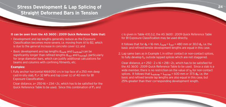
it can be seen from the as 3600 : 2009 Quick Reference table that:
• Development and lap lengths generally reduce as the Exposure Classification becomes more severe, i.e. moving from A1 to B2, which is due to the general increase in concrete cover (c); and
• Basic development and lap lengths (Lsy.tb and Lsy.tb.lap) can be significantly longer than refined lengths (Lsy.t and Lsy.t.lap), particularly for large diameter bars, which can justify additional calculations for beams and columns with confining fitments, etc.
Examples:
1. Fully anchor horizontal N16@250 crs in top face of a 250 mm deep cast-in-situ slab, f’C= 32 MPa and top cover (c) of 40 mm for B1 Exposure Classification.
Clear distance, a= 250-16 = 234 > 2c, which has to be satisfied for the Quick Reference Table to be used. Since this combination of f’C and
c is given in Table 4.10.3.2, the AS 3600 : 2009 Quick Reference Table for B1 Exposure Classification may be used directly.
It follows that for db = 16 mm, Lsy.tb = Lsy.t = 480 mm or 30.0 db, i.e. the basic and refined tensile development lengths are equal in this case.
2. Lap same bars as in Example 1, in either contact or non-contact splices, to fully develop fsy outside lapped splices which are not staggered.
Clear distance, a = 250 - 2 x 16 = 218 > 2c, which has to be satisfied for the AS 3600 : 2009 Quick Reference Table to be used. Since a slab is a wide member, there is no restriction on the value of sb for non-contact splices. It follows that Lsy.tb.lap = Lsy.t.lap = 600 mm or 37.5 db, i.e. the basic and refined tensile lap lengths are also equal in this case, but 25% greater than their corresponding development length.
25
www.reinforcing.com | www.reinforcing.tv 25
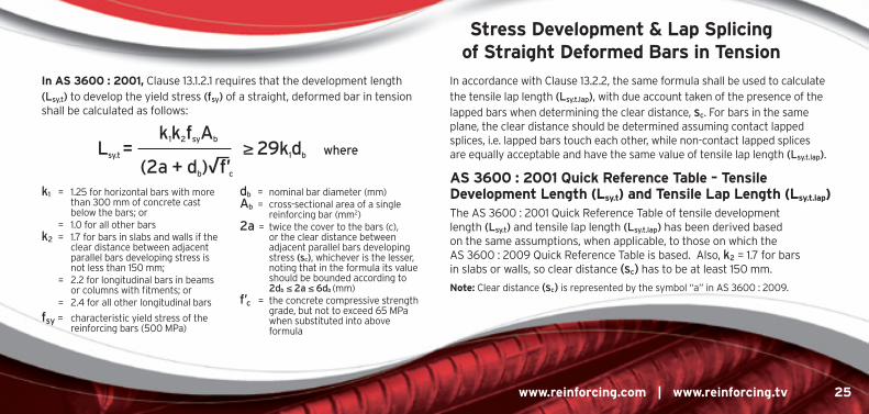
in as 3600 : 2001, Clause 13.1.2.1 requires that the development length (Lsy.t) to develop the yield stress (fsy) of a straight, deformed bar in tension shall be calculated as follows:
In accordance with Clause 13.2.2, the same formula shall be used to calculate the tensile lap length (Lsy.t.lap), with due account taken of the presence of the lapped bars when determining the clear distance, sc. For bars in the same plane, the clear distance should be determined assuming contact lapped splices, i.e. lapped bars touch each other, while non-contact lapped splices are equally acceptable and have the same value of tensile lap length (Lsy.t.lap).
as 3600 : 2001 Quick Reference table – tensile Development length (lsy.t) and tensile lap length (lsy.t.lap) The AS 3600 : 2001 Quick Reference Table of tensile development length (Lsy.t) and tensile lap length (Lsy.t.lap) has been derived based on the same assumptions, when applicable, to those on which the AS 3600 : 2009 Quick Reference Table is based. Also, k2 = 1.7 for bars in slabs or walls, so clear distance (sc) has to be at least 150 mm.
note: Clear distance (sc) is represented by the symbol “a” in AS 3600 : 2009.
k1 = 1.25 for horizontal bars with more than 300 mm of concrete cast below the bars; or
= 1.0 for all other bars k2 = 1.7 for bars in slabs and walls if the
clear distance between adjacent parallel bars developing stress is not less than 150 mm;
= 2.2 for longitudinal bars in beams or columns with fitments; or
= 2.4 for all other longitudinal bars
fsy = characteristic yield stress of the reinforcing bars (500 MPa)
db = nominal bar diameter (mm) Ab = cross-sectional area of a single
reinforcing bar (mm2) 2a = twice the cover to the bars (c),
or the clear distance between adjacent parallel bars developing stress (sc), whichever is the lesser, noting that in the formula its value should be bounded according to 2db ≤ 2a ≤ 6db (mm)
f’c = the concrete compressive strength grade, but not to exceed 65 MPa when substituted into above formula
Lsy.t = k1k2fsyAb
≥ 29k1db where
(2a + db)√f’c
stress Development & lap splicing of straight Deformed Bars in tension
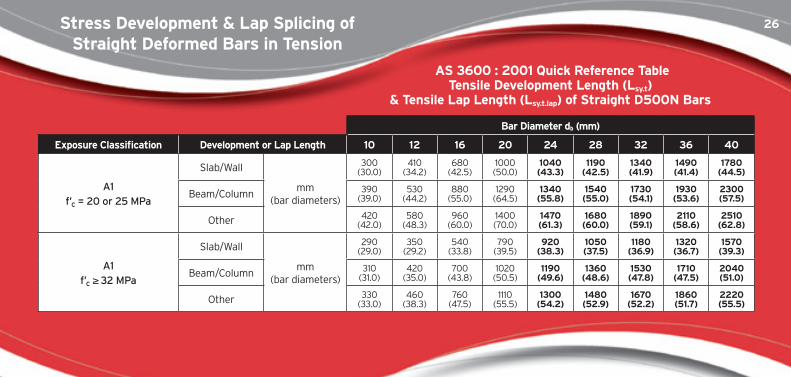
26
Bar Diameter db (mm)
Exposure classification Development or lap length 10 12 16 20 24 28 32 36 40
A1f’c = 20 or 25 MPa
Slab/Wall
mm (bar diameters)
300 (30.0)
410(34.2)
680 (42.5)
1000 (50.0)
1040 (43.3)
1190 (42.5)
1340 (41.9)
1490 (41.4)
1780 (44.5)
Beam/Column 390 (39.0)
530 (44.2)
880 (55.0)
1290 (64.5)
1340 (55.8)
1540 (55.0)
1730 (54.1)
1930 (53.6)
2300 (57.5)
Other 420 (42.0)
580 (48.3)
960 (60.0)
1400 (70.0)
1470 (61.3)
1680 (60.0)
1890 (59.1)
2110 (58.6)
2510 (62.8)
A1f’c ≥ 32 MPa
Slab/Wall
mm (bar diameters)
290 (29.0)
350(29.2)
540 (33.8)
790 (39.5)
920 (38.3)
1050 (37.5)
1180 (36.9)
1320 (36.7)
1570 (39.3)
Beam/Column 310 (31.0)
420 (35.0)
700 (43.8)
1020 (50.5)
1190 (49.6)
1360 (48.6)
1530 (47.8)
1710 (47.5)
2040 (51.0)
Other 330(33.0)
460 (38.3)
760(47.5)
1110(55.5)
1300 (54.2)
1480 (52.9)
1670 (52.2)
1860 (51.7)
2220(55.5)
as 3600 : 2001 Quick Reference tabletensile Development length (lsy.t)
& tensile lap length (lsy.t.lap) of straight D500n Bars
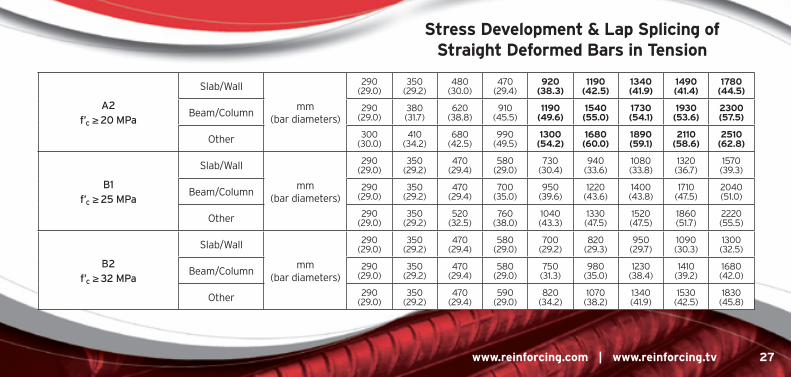
stress Development & lap splicing of straight Deformed Bars in tension
27
www.reinforcing.com | www.reinforcing.tv 27
A2f’c ≥ 20 MPa
Slab/Wall
mm (bar diameters)
290 (29.0)
350(29.2)
480 (30.0)
470 (29.4)
920 (38.3)
1190 (42.5)
1340 (41.9)
1490 (41.4)
1780 (44.5)
Beam/Column 290 (29.0)
380 (31.7)
620 (38.8)
910 (45.5)
1190 (49.6)
1540 (55.0)
1730 (54.1)
1930 (53.6)
2300 (57.5)
Other 300 (30.0)
410(34.2)
680 (42.5)
990 (49.5)
1300 (54.2)
1680 (60.0)
1890 (59.1)
2110 (58.6)
2510 (62.8)
B1f’c ≥ 25 MPa
Slab/Wall
mm (bar diameters)
290 (29.0)
350(29.2)
470 (29.4)
580 (29.0)
730 (30.4)
940 (33.6)
1080 (33.8)
1320 (36.7)
1570 (39.3)
Beam/Column 290 (29.0)
350(29.2)
470 (29.4)
700 (35.0)
950 (39.6)
1220 (43.6)
1400 (43.8)
1710(47.5)
2040 (51.0)
Other 290 (29.0)
350(29.2)
520 (32.5)
760 (38.0)
1040 (43.3)
1330 (47.5)
1520 (47.5)
1860 (51.7)
2220 (55.5)
B2f’c ≥ 32 MPa
Slab/Wall
mm (bar diameters)
290 (29.0)
350(29.2)
470 (29.4)
580 (29.0)
700 (29.2)
820 (29.3)
950(29.7)
1090 (30.3)
1300 (32.5)
Beam/Column 290 (29.0)
350(29.2)
470 (29.4)
580 (29.0)
750 (31.3)
980 (35.0)
1230 (38.4)
1410 (39.2)
1680 (42.0)
Other 290 (29.0)
350(29.2)
470 (29.4)
590 (29.0)
820 (34.2)
1070 (38.2)
1340 (41.9)
1530 (42.5)
1830 (45.8)
stress Development & lap splicing ofstraight Deformed Bars in tension
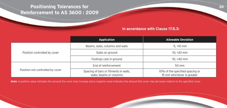
28Positioning tolerances forReinforcement to as 3600 : 2009
application allowable Deviation
Position controlled by cover
Beams, slabs, columns and walls -5, +10 mm
Slabs on ground -10, +20 mm
Footings cast in ground -10, +40 mm
Position not controlled by cover
End of reinforcement 50 mm
Spacing of bars or fitments in walls, slabs, beams or columns
10% of the specified spacing or 15 mm whichever is greater
note: A positive value indicates the amount the cover may increase and a negative value indicates the amount the cover may decrease relative to the specified cover.
in accordance with clause 17.5.3:
29
www.reinforcing.com | www.reinforcing.tv 29
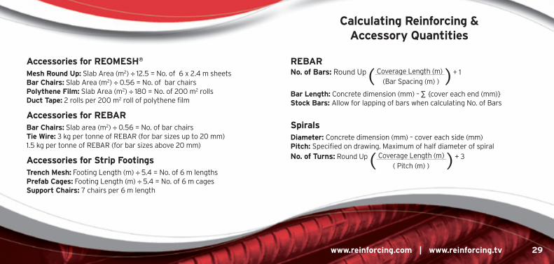
calculating Reinforcing & accessory Quantities
accessories for REomEsh® mesh Round Up: Slab Area (m2) ÷ 12.5 = No. of 6 x 2.4 m sheets Bar chairs: Slab Area (m2) ÷ 0.56 = No. of bar chairs Polythene film: Slab Area (m2) ÷ 180 = No. of 200 m2 rolls Duct tape: 2 rolls per 200 m2 roll of polythene film
accessories for REBaR Bar chairs: Slab area (m2) ÷ 0.56 = No. of bar chairs tie Wire: 3 kg per tonne of REBAR (for bar sizes up to 20 mm) 1.5 kg per tonne of REBAR (for bar sizes above 20 mm)
accessories for strip footings trench mesh: Footing Length (m) ÷ 5.4 = No. of 6 m lengths Prefab cages: Footing Length (m) ÷ 5.4 = No. of 6 m cages support chairs: 7 chairs per 6 m length
REBaR no. of Bars: Round Up ( Coverage Length (m) ) + 1 (Bar Spacing (m) )
Bar length: Concrete dimension (mm) – ∑ {cover each end (mm)} stock Bars: Allow for lapping of bars when calculating No. of Bars
spirals Diameter: Concrete dimension (mm) – cover each side (mm) Pitch: Specified on drawing. Maximum of half diameter of spiral no. of turns: Round Up ( Coverage Length (m) ) + 3 ( Pitch (m) )
30500PlUs® REBaRstandard hooks and cogs
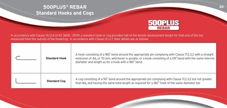
In accordance with Clause 13.1.2.6 of AS 3600 : 2009, a standard hook or cog provides half of the tensile development length for that end of the bar, measured from the outside of the hook/cog. In accordance with Clause 13.1.2.7, their details are as follows.
standard hookA hook consisting of a 180
o bend around the appropriate pin complying with Clause 17.2.3.2 with a straight
extension of 4db or 70 mm, whichever is greater, or a hook consisting of a 135o bend with the same internal
diameter and length as for a hook with a 180o bend
standard cogA cog consisting of a 90
o bend around the appropriate pin complying with Clause 17.2.3.2 but not greater
than 8db and having the same total length as required for a 180o hook of the same diameter bar
REBAR
31
www.reinforcing.com | www.reinforcing.tv 31
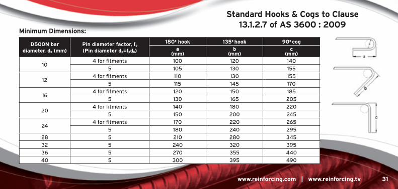
standard hooks & cogs to clause 13.1.2.7 of as 3600 : 2009
D500n bar diameter, db (mm)
Pin diameter factor, fp (Pin diameter dp=fpdb)
180o hook 135o hook 90o coga
(mm)b
(mm)c
(mm)
104 for fitments 100 120 140
5 105 130 155
124 for fitments 110 130 155
5 115 145 170
164 for fitments 120 150 185
5 130 165 205
204 for fitments 140 180 220
5 150 200 245
244 for fitments 170 220 265
5 180 240 295
28 5 210 280 345
32 5 240 320 395
36 5 270 355 440
40 5 300 395 490
minimum Dimensions:
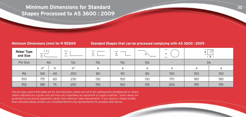
32minimum Dimensions for standard shapes Processed to as 3600 : 2009
Rebar type and size
Pin Size 4db 5db 5db 5db 5db - 3db
a* b a* a a a a a a
R6 165 40 200 80 90 80 150 150 150
R10 175 60 230 130 150 130 170 180 180
R12 185 75 250 155 160 155 200 195 195
The pin sizes used in this table are for mild steel bars, which are not to be subsequently straightened or rebent. Values indicated are a guide only and may vary depending on equipment of supply locations. Some values are governed by processing equipment rather than minimum code requirements. If you require a shape smaller than indicated please contact your OneSteel Reinforcing representative for possible alternatives.
minimum Dimensions (mm) for R REBaR standard shapes that can be processed complying with as 3600 : 2009
33
www.reinforcing.com | www.reinforcing.tv 33
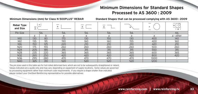
minimum Dimensions for standard shapes Processed to as 3600 : 2009
Rebar type and size
Pin Size 5db 5db 5db 5db 5db - 4db
a b a a a a a a - otherN10 130 80 170 130 150 130 400 140N12 135 95 190 160 160 155 400 160N16 150 125 220 210 210 210 420 210N20 175 155 260 260 260 260 500 260N24 205 185 315 315 315 315 550 315N28 235 220 365 365 365 365 600 365N32 265 250 420 420 420 420 800 420N36 295 280 470 470 470 470 1000 -N40 325 310 520 520 520 520 1200 -
minimum Dimensions (mm) for class n 500PlUs® REBaR standard shapes that can be processed complying with as 3600 : 2009
The pin sizes used in this table are for hot-rolled deformed bars, which are not to be subsequently straightened or rebent. Values indicated are a guide only and may vary depending on equipment of supply locations. Some values are governed by processing equipment rather than minimum code requirements. If you require a shape smaller than indicated please contact your OneSteel Reinforcing representative for possible alternatives.
34Processing 500PlUs® REBaR to as 3600 : 2009
technical note
Rebar Bending and Rebending / straightening Standard names and use:
• Bending of 500PLUS® REBAR should be carried out in accordance with Clause 17.2.3 of AS 3600 : 2009
• If engineers/builders request pin diameters smaller than those required by AS 3600, such bends can only be supplied if the engineer gives written approval to the order.
• Rebending 500PLUS® REBAR on site – due to limitations of adequate rebending facilities on site, we recommend that the customer’s attention is drawn to the guidelines set out in AS 3600 and in the OneSteel Reinforcing 500PLUS® technical notes.
• Care must be taken when bending, straightening or rebending is performed on a construction site to ensure that the bend radii are not formed below the prescribed minimum sizes in AS 3600.
• OneSteel Reinforcing recommends that 500PLUS® TEMPCORE® be used in such situations for use as pull-out bars rather than MICROALLOY or CONTISTRETCH rebar.
note: TEMPCORE®, MICROALLOY and CONTISTRETCH and all galvanized rebar have different minimum recommended bending pin diameters.
REBAR
35
www.reinforcing.com | www.reinforcing.tv 35
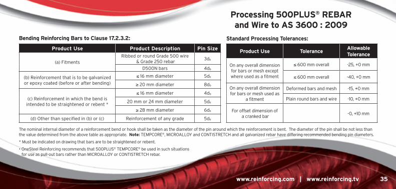
Processing 500PlUs® REBaR and Wire to as 3600 : 2009
The nominal internal diameter of a reinforcement bend or hook shall be taken as the diameter of the pin around which the reinforcement is bent. The diameter of the pin shall be not less than the value determined from the above table as appropriate. note: TEMPCORE®, MICROALLOY and CONTISTRETCH and all galvanized rebar have differing recommended bending pin diameters.
* Must be indicated on drawing that bars are to be straightened or rebent.
• OneSteel Reinforcing recommends that 500PLUS® TEMPCORE® be used in such situations for use as pull-out bars rather than MICROALLOY or CONTISTRETCH rebar.
Product Use Product Description Pin size
(a) Fitments Ribbed or round Grade 500 wire
& Grade 250 rebar3db
D500N bars 4db
(b) Reinforcement that is to be galvanized or epoxy coated (before or after bending)
≤ 16 mm diameter 5db
≥ 20 mm diameter 8db
(c) Reinforcement in which the bend is intended to be straightened or rebent *
≤ 16 mm diameter 4db
20 mm or 24 mm diameter 5db
≥ 28 mm diameter 6db
(d) Other than specified in (b) or (c) Reinforcement of any grade 5db
Bending Reinforcing Bars to clause 17.2.3.2:
Product Use tolerance allowable tolerance
On any overall dimension for bars or mesh except where used as a fitment
≤ 600 mm overall -25, +0 mm
≤ 600 mm overall -40, +0 mm
On any overall dimension for bars or mesh used as
a fitment
Deformed bars and mesh -15, +0 mm
Plain round bars and wire -10, +0 mm
For offset dimension of a cranked bar
-0, +10 mm
standard Processing tolerances:
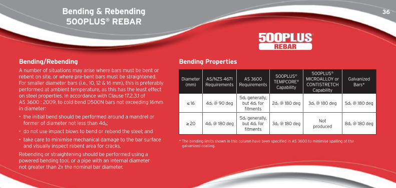
36Bending & Rebending500PlUs® REBaR
Diameter (mm)
AS/NZS 4671 Requirements
AS 3600 Requirements
500PLUS® TEMPCORE®
Capability
500PLUS® MICROALLOY or CONTISTRETCH
Capability
Galvanized Bars*
≤ 16 4db @ 90 deg5db generally,
but 4db for fitments
2db @ 180 deg 3db @ 180 deg 5db @ 180 deg
≥ 20 4db @ 180 deg5db generally,
but 4db for fitments
3db @ 180 degNot
produced8db @ 180 deg
* The bending limits shown in this column have been specified in AS 3600 to minimise spalling of the galvanized coating.
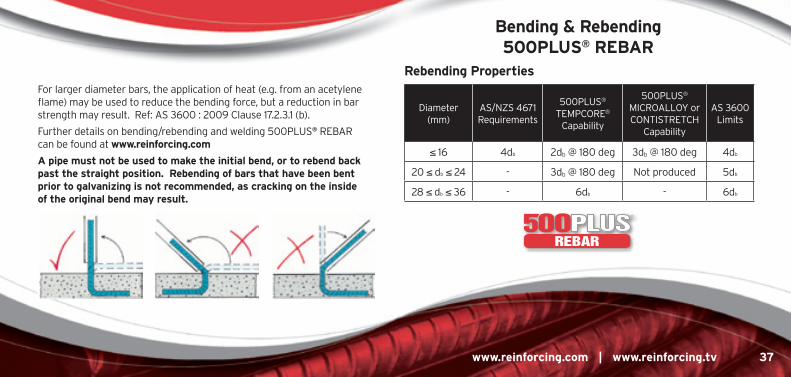
Bending/Rebending A number of situations may arise where bars must be bent or rebent on site, or where pre-bent bars must be straightened. For smaller diameter bars (i.e., 10, 12 & 16 mm), this is preferably performed at ambient temperature, as this has the least effect on steel properties. In accordance with Clause 17.2.3.1 of AS 3600 : 2009, to cold bend D500N bars not exceeding 16mm in diameter:
• the initial bend should be performed around a mandrel or former of diameter not less than 4db;
• do not use impact blows to bend or rebend the steel; and
• take care to minimise mechanical damage to the bar surface and visually inspect rebent area for cracks.
Rebending or straightening should be performed using a powered bending tool, or a pipe with an internal diameter not greater than 2x the nominal bar diameter.
Bending Properties
REBAR
37
www.reinforcing.com | www.reinforcing.tv 37
Bending & Rebending 500PlUs® REBaR
Diameter (mm)
AS/NZS 4671 Requirements
500PLUS® TEMPCORE®
Capability
500PLUS® MICROALLOY or CONTISTRETCH
Capability
AS 3600 Limits
≤ 16 4db 2db @ 180 deg 3db @ 180 deg 4db
20 ≤ db ≤ 24 - 3db @ 180 deg Not produced 5db
28 ≤ db ≤ 36 - 6db - 6db
For larger diameter bars, the application of heat (e.g. from an acetylene flame) may be used to reduce the bending force, but a reduction in bar strength may result. Ref: AS 3600 : 2009 Clause 17.2.3.1 (b).
Further details on bending/rebending and welding 500PLUS® REBAR can be found at www.reinforcing.com
a pipe must not be used to make the initial bend, or to rebend back past the straight position. Rebending of bars that have been bent prior to galvanizing is not recommended, as cracking on the inside of the original bend may result.
Rebending Properties
REBAR
38heating & Welding500PlUs® REBaR
After heating, the resultant ambient temperature properties of reinforcing steels may be significantly altered. This is an important consideration if heat has been applied to assist with bending bars through welding or the effect of fire. To effectively control the temperature during the heating or welding process the use of temperature control crayons is recommended.
heating Heating should be avoided if the original bar properties are required. Bending should always be around a former of the appropriate size (refer processing to AS 3600). AS 3600 : 2001 states in Clause 19.2.3.1 and AS 3600 : 2009 in Clause 17.2.3.1 that reinforcement may be bent hot, provided that all of the following are complied with:
i) the steel is heated uniformly through & beyond the portion to be bent;
ii) the temperature of the steel does not exceed 600oC;
iii) the bar is not cooled by quenching; and
iv) if during heating the temperature of the bar exceeds 450oC, the characteristic yield stress (fsy) of the steel after bending shall be taken as 250 MPa.
Welding 500PLUS® REBAR produced by the TEMPCORE®, MICROALLOYED and CONTISTRETCH processes has maximum carbon equivalent (Ceq) of 0.44 and, as such, requires no pre-heating prior to welding.
Pre-heating is not required when bars are welded in accordance with AS/NZS 1554 Part 3. Hydrogen controlled electrodes are required for all weld types, and matching strength electrodes are required for butt welds.
note: Some types of welded splices can reduce the ductility of the connected bars.
REBAR
39
www.reinforcing.com | www.reinforcing.tv 39
threading 500PlUs® REBaR
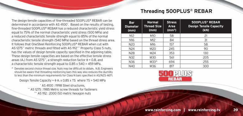
The design tensile capacities of fine-threaded 500PLUS® REBAR can be determined in accordance with AS 4100*. Based on the results of testing, fine-threaded 500PLUS® REBAR has a reduced characteristic yield stress equal to 75% of the normal characteristic yield stress (500 MPa) and a reduced characteristic tensile strength equal to 85% of the normal characteristic tensile strength (540 MPa) based on the thread stress area. It follows that OneSteel Reinforcing 500PLUS® REBAR when cut with AS 1275** metric threads and fitted with AS 1112*** Property Class 5 nuts, has the values of design tensile capacity specified in the adjoining table. These design tensile capacities are based on the effective tensile stress areas (As) from AS 1275**, a strength reduction factor f = 0.8, and a characteristic tensile strength equal to 0.85 x 540 = 459 MPa.
^ Denotes second choice thread size. Nuts may be difficult to obtain. N.B. Engineers should be aware that threading reinforcing bars this way also reduces the ductility to less than the minimum requirements for Class N bars specified in AS/NZS 4671.
Design Tensile Capacity = f As x 0.85 x TS where TS = 540 MPa
* AS 4100 : 1998 Steel structures, ** AS 1275 : 1985 Metric screw threads for fasteners
*** AS 1112 : 2000 ISO metric hexagon nuts
Bar Diameter
(mm)
normal thread size
(mm)
stress area
(mm2)
500PlUs® REBaR Design tensile capacity
(kn)
N12 M10 58 21N16 M12 84 31N20 M16 157 58N24 M20 245 90N28 M24 353 130N32 M30 561 205N36 M33^ 694 255N40 M36 817 300
REBAR
40
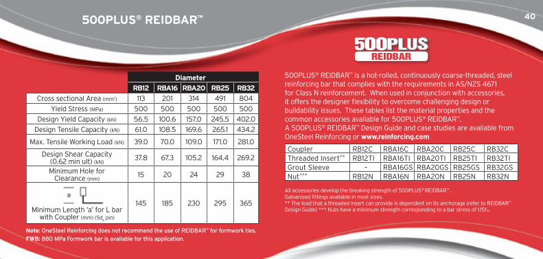
500PLUS® REIDBAR™ is a hot-rolled, continuously coarse-threaded, steel reinforcing bar that complies with the requirements in AS/NZS 4671 for Class N reinforcement. When used in conjunction with accessories, it offers the designer flexibility to overcome challenging design or buildability issues. These tables list the material properties and the common accessories available for 500PLUS® REIDBAR™. A 500PLUS® REIDBAR™ Design Guide and case studies are available from OneSteel Reinforcing or www.reinforcing.com
All accessories develop the breaking strength of 500PLUS® REIDBAR™ . Galvanized fittings available in most sizes. ** The load that a threaded insert can provide is dependent on its anchorage (refer to REIDBAR™ Design Guide) *** Nuts have a minimum strength corresponding to a bar stress of 1.15fsy
Bar Diameter (mm)
RB12 RBa16 RBa20 RB25 RB32
Cross sectional Area (mm2) 113 201 314 491 804
Yield Stress (MPa) 500 500 500 500 500
Design Yield Capacity (kN) 56.5 100.6 157.0 245.5 402.0
Design Tensile Capacity (kN) 61.0 108.5 169.6 265.1 434.2
Max. Tensile Working Load (kN) 39.0 70.0 109.0 171.0 281.0
Design Shear Capacity (0.62 min ult) (kN)
37.8 67.3 105.2 164.4 269.2
Minimum Hole for Clearance (mm)
15 20 24 29 38
Minimum Length ‘a’ for L bar with Coupler (mm) (5d
b pin)
145 185 230 295 365
Coupler RB12C RBA16C RBA20C RB25C RB32CThreaded Insert** RB12TI RBA16TI RBA20TI RB25TI RB32TIGrout Sleeve – RBA16GS RBA20GS RB25GS RB32GSNut*** RB12N RBA16N RBA20N RB25N RB32N
note: OneSteel Reinforcing does not recommend the use of REIDBAR™ for formwork ties.fWB: 880 MPa Formwork bar is available for this application.
500PlUs® REiDBaR™
REIDBAR
41
www.reinforcing.com | www.reinforcing.tv 41
500PlUs® PREfaB
PREFAB
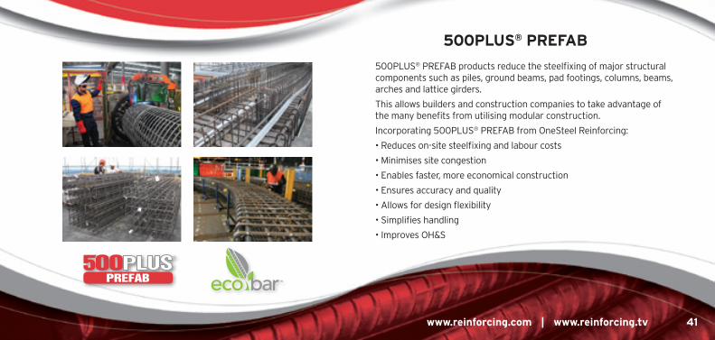
500PLUS® PREFAB products reduce the steelfixing of major structural components such as piles, ground beams, pad footings, columns, beams, arches and lattice girders.
This allows builders and construction companies to take advantage of the many benefits from utilising modular construction.
Incorporating 500PLUS® PREFAB from OneSteel Reinforcing:
• Reduces on-site steelfixing and labour costs
• Minimises site congestion
• Enables faster, more economical construction
• Ensures accuracy and quality
• Allows for design flexibility
• Simplifies handling
• Improves OH&S
42500PlUs® BamtEc® Reinforcing carpets
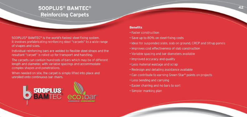
500PLUS® BAMTEC® is the world’s fastest steel fixing system. It involves prefabricating reinforcing steel “carpets” to a wide range of shapes and sizes.
Individual reinforcing bars are welded to flexible steel straps and the resultant “carpet” is rolled up for transport and handling.
The carpets can contain hundreds of bars which may be of different length and diameter, with variable spacings and accommodate complex shapes and penetrations.
When needed on site, the carpet is simply lifted into place and unrolled onto continuous bar chairs.
Benefits
• Faster construction
• Save up to 80% on steel-fixing costs
• Ideal for suspended slabs, slab on ground, CRCP and tilt-up panels
• Improves cost effectiveness of slab construction
• Variable spacing and bar diameters available
• Improved accuracy and quality
• Less material wastage and scrap
• Redesign and detailing assistance available
• Can contribute to earning Green Star® points on projects
• Less bending and carrying
• Easier chairing and no bars to sort
• Simpler marking plan
43
www.reinforcing.com | www.reinforcing.tv 43
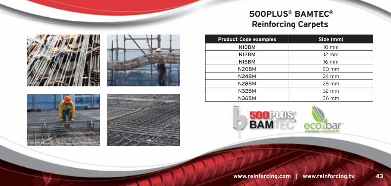
Product code examples size (mm)
N10BM 10 mm
N12BM 12 mm
N16BM 16 mm
N20BM 20 mm
N24BM 24 mm
N28BM 28 mm
N32BM 32 mm
N36BM 36 mm
500PlUs® BamtEc® Reinforcing carpets
44tRUssDEK® long span structural Decking
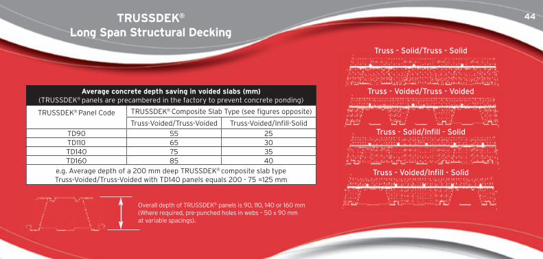
Truss - Solid/Truss - Solid
Truss - Voided/Truss - Voided
Truss - Solid/Infill - Solid
Truss - Voided/Infill - Solid
average concrete depth saving in voided slabs (mm)(TRUSSDEK® panels are precambered in the factory to prevent concrete ponding)
TRUSSDEK® Panel Code TRUSSDEK® Composite Slab Type (see figures opposite)
Truss-Voided/Truss-Voided Truss-Voided/Infill-Solid
TD90 55 25TD110 65 30TD140 75 35TD160 85 40
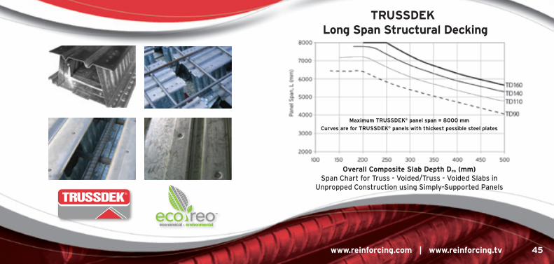
e.g. Average depth of a 200 mm deep TRUSSDEK® composite slab type Truss-Voided/Truss-Voided with TD140 panels equals 200 - 75 =125 mm
Overall depth of TRUSSDEK® panels is 90, 110, 140 or 160 mm (Where required, pre-punched holes in webs – 50 x 90 mm at variable spacings).
45
www.reinforcing.com | www.reinforcing.tv 45
tRUssDEK® long span structural Decking
overall composite slab Depth Dcs (mm)Span Chart for Truss - Voided/Truss - Voided Slabs in
Unpropped Construction using Simply-Supported Panels
maximum tRUssDEK® panel span = 8000 mm
curves are for tRUssDEK® panels with thickest possible steel plates
TRUSSDEK
46500PlUs® RomtEch® tunnel Girders
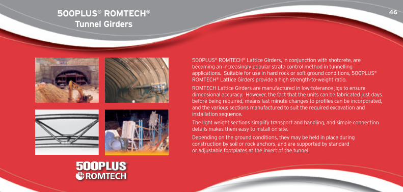
500PLUS® ROMTECH® Lattice Girders, in conjunction with shotcrete, are becoming an increasingly popular strata control method in tunnelling applications. Suitable for use in hard rock or soft ground conditions, 500PLUS® ROMTECH® Lattice Girders provide a high strength-to-weight ratio.
ROMTECH Lattice Girders are manufactured in low-tolerance jigs to ensure dimensional accuracy. However, the fact that the units can be fabricated just days before being required, means last minute changes to profiles can be incorporated, and the various sections manufactured to suit the required excavation and installation sequence.
The light weight sections simplify transport and handling, and simple connection details makes them easy to install on site.
Depending on the ground conditions, they may be held in place during construction by soil or rock anchors, and are supported by standard or adjustable footplates at the invert of the tunnel.
47
www.reinforcing.com | www.reinforcing.tv 47
PoolstEEl®
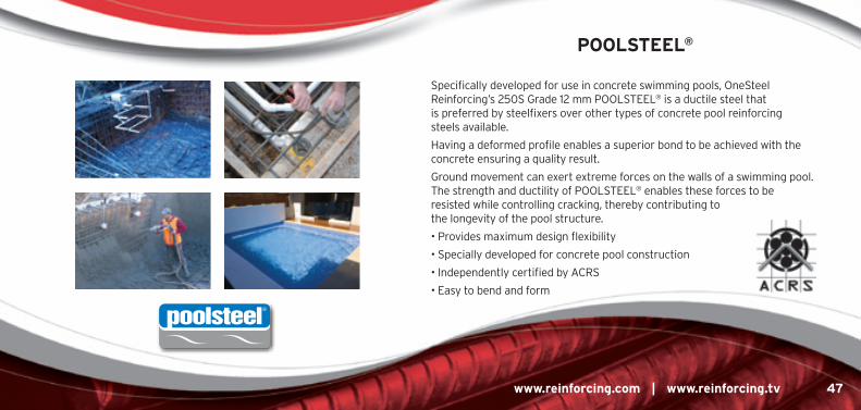
Specifically developed for use in concrete swimming pools, OneSteel Reinforcing’s 250S Grade 12 mm POOLSTEEL® is a ductile steel that is preferred by steelfixers over other types of concrete pool reinforcing steels available.
Having a deformed profile enables a superior bond to be achieved with the concrete ensuring a quality result.
Ground movement can exert extreme forces on the walls of a swimming pool. The strength and ductility of POOLSTEEL® enables these forces to be resisted while controlling cracking, thereby contributing to the longevity of the pool structure.
• Provides maximum design flexibility
• Specially developed for concrete pool construction
• Independently certified by ACRS
• Easy to bend and form
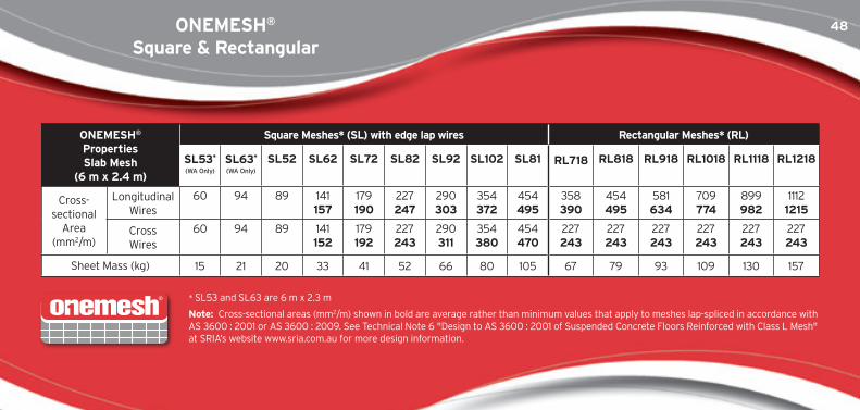
48onEmEsh® square & Rectangular
onEmEsh® Properties slab mesh
(6 m x 2.4 m)
square meshes* (sl) with edge lap wires Rectangular meshes* (Rl)
sl53*
(WA Only)
sl63*
(WA Only)
sl52 sl62 sl72 sl82 sl92 sl102 sl81 Rl718 Rl818 Rl918 Rl1018 Rl1118 Rl1218
Cross-sectional
Area (mm2/m)
Longitudinal Wires
60 94 89 141 157
179 190
227 247
290 303
354 372
454 495
358 390
454 495
581 634
709 774
899 982
1112 1215
Cross Wires
60 94 89 141 152
179 192
227 243
290 311
354 380
454 470
227 243
227 243
227 243
227 243
227 243
227 243
Sheet Mass (kg) 15 21 20 33 41 52 66 80 105 67 79 93 109 130 157
* SL53 and SL63 are 6 m x 2.3 m
note: Cross-sectional areas (mm2/m) shown in bold are average rather than minimum values that apply to meshes lap-spliced in accordance with AS 3600 : 2001 or AS 3600 : 2009. See Technical Note 6 "Design to AS 3600 : 2001 of Suspended Concrete Floors Reinforced with Class L Mesh" at SRIA’s website www.sria.com.au for more design information.
49
www.reinforcing.com | www.reinforcing.tv 49
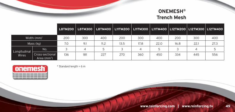
onEmEsh®
trench mesh
l8tm200 l8tm300 l8tm400 l11tm200 l11tm300 l11tm400 l12tm200 l12tm300 l12tm400
Width (mm)* 200 300 400 200 300 400 200 300 400
Mass (kg) 7.0 9.1 11.2 13.5 17.8 22.0 16.8 22.1 27.3
Longitudinal Wires
No. 3 4 5 3 4 5 3 4 5
Cross-sectional Area (mm2)
136 181 227 270 360 450 334 445 556
* Standard length = 6 m
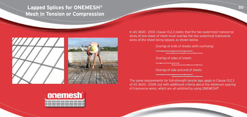
50lapped splices for onEmEsh® mesh in tension or compression
In AS 3600 : 2001, Clause 13.2.3 states that the two outermost transverse wires of one sheet of mesh must overlap the two outermost transverse wires of the sheet being lapped, as shown below.
Overlap of ends of sheets (with overhang)
Overlap of sides of sheets
Overlap of side and end of sheets
The same requirements for full-strength tensile laps apply in Clause 13.2.3 of AS 3600 : 2009, but with additional criteria about the minimum spacing of transverse wires, which are all satisfied by using ONEMESH®.
51
www.reinforcing.com | www.reinforcing.tv 51
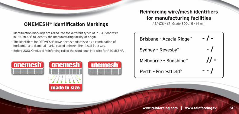
Reinforcing wire/mesh identifiers for manufacturing facilities
AS/NZS 4671 Grade 500L: 5 – 14 mm
Brisbane - Acacia Ridge™ - / -
Sydney – Revesby™ - /
Melbourne – Sunshine™ // -
Perth – Forrestfield™ - - /
• Identification markings are rolled into the different types of REBAR and wire in REOMESH® to identify the manufacturing facility of origin.
• The identifiers for REOMESH® have been standardised as a combination of horizontal and diagonal marks placed between the ribs at intervals.
• Before 2010, OneSteel Reinforcing rolled the word ‘one’ into wire for REOMESH®.
onEmEsh® identification markings
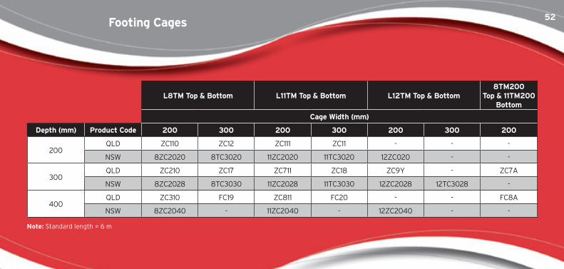
52footing cages
l8tm top & Bottom l11tm top & Bottom l12tm top & Bottom8tm200
top & 11tm200 Bottom
cage Width (mm)
Depth (mm) Product code 200 300 200 300 200 300 200
200QLD ZC110 ZC12 ZC111 ZC11 - - -
NSW 8ZC2020 8TC3020 11ZC2020 11TC3020 12ZC020 - -
300QLD ZC210 ZC17 ZC711 ZC18 ZC9Y - ZC7A
NSW 8ZC2028 8TC3030 11ZC2028 11TC3030 12ZC2028 12TC3028 -
400QLD ZC310 FC19 ZC811 FC20 - - FC8A
NSW 8ZC2040 - 11ZC2040 - 12ZC2040 - -
note: Standard length = 6 m
53
www.reinforcing.com | www.reinforcing.tv 53
UtEmEsh®
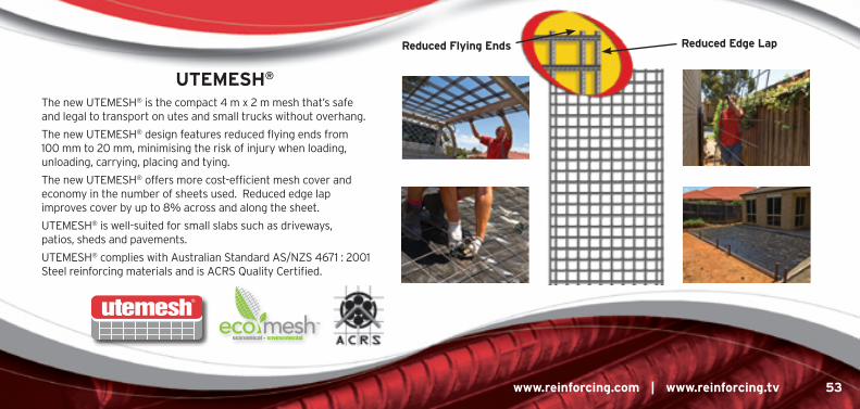
The new UTEMESH® is the compact 4 m x 2 m mesh that’s safe and legal to transport on utes and small trucks without overhang.
The new UTEMESH® design features reduced flying ends from 100 mm to 20 mm, minimising the risk of injury when loading, unloading, carrying, placing and tying.
The new UTEMESH® offers more cost-efficient mesh cover and economy in the number of sheets used. Reduced edge lap improves cover by up to 8% across and along the sheet.
UTEMESH® is well-suited for small slabs such as driveways, patios, sheds and pavements.
UTEMESH® complies with Australian Standard AS/NZS 4671 : 2001 Steel reinforcing materials and is ACRS Quality Certified.
Reduced Edge lapReduced flying Ends
54hanDimEsh® General Purpose mesh
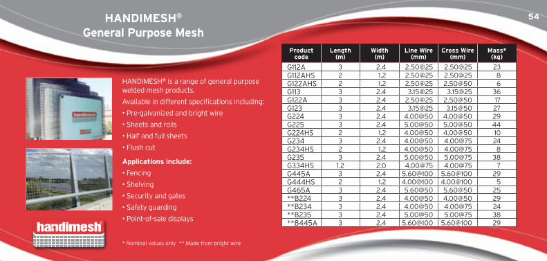
hanDimEsh® shEEtsHANDIMESH® is a range of general purpose welded mesh products.
Available in different specifications including:
• Pre-galvanized and bright wire
• Sheets and rolls
• Half and full sheets
• Flush cut
applications include:
• Fencing
• Shelving
• Security and gates
• Safety guarding
• Point-of-sale displays
Product code
length (m)
Width (m)
line Wire (mm)
cross Wire (mm)
mass* (kg)
G112A 3 2.4 2.50@25 2.50@25 23G112AHS 2 1.2 2.50@25 2.50@25 8G122AHS 2 1.2 2.50@25 2.50@50 6G113 3 2.4 3.15@25 3.15@25 36G122A 3 2.4 2.50@25 2.50@50 17G123 3 2.4 3.15@25 3.15@50 27G224 3 2.4 4.00@50 4.00@50 29G225 3 2.4 5.00@50 5.00@50 44G224HS 2 1.2 4.00@50 4.00@50 10G234 3 2.4 4.00@50 4.00@75 24G234HS 2 1.2 4.00@50 4.00@75 8G235 3 2.4 5.00@50 5.00@75 38G334HS 1.2 2.0 4.00@75 4.00@75 7G445A 3 2.4 5.60@100 5.60@100 29G444HS 2 1.2 4.00@100 4.00@100 5G465A 3 2.4 5.60@50 5.60@50 25**B224 3 2.4 4.00@50 4.00@50 29**B234 3 2.4 4.00@50 4.00@75 24**B235 3 2.4 5.00@50 5.00@75 38**B445A 3 2.4 5.60@100 5.60@100 29
* Nominal values only ** Made from bright wire
55
www.reinforcing.com | www.reinforcing.tv 55
iRonBaRK® Rural mesh
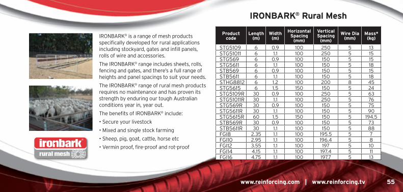
IRONBARK® is a range of mesh products specifically developed for rural applications including stockyard, gates and infill panels, rolls of wire and accessories.
The IRONBARK® range includes sheets, rolls, fencing and gates, and there’s a full range of heights and panel spacings to suit your needs.
The IRONBARK® range of rural mesh products requires no maintenance and has proven its strength by enduring our tough Australian conditions year in, year out.
The benefits of IRONBARK® include:
• Secure your livestock
• Mixed and single stock farming
• Sheep, pig, goat, cattle, horse etc
• Vermin proof, fire-proof and rot-proofrural mesh
Product code
length (m)
Width (m)
horizontal spacing
(mm)
Vertical spacing
(mm)
Wire Dia (mm)
mass* (kg)
STG5109 6 0.9 100 250 5 13STG51011 6 1.1 100 250 5 15STG569 6 0.9 100 150 5 15STG5611 6 1.1 100 150 5 18STB569 6 0.9 100 150 5 15STB5611 6 1.1 100 150 5 18STHG8812 6 1.2 100 200 8 45STG5615 6 1.5 150 150 5 24STG5109R 30 0.9 100 250 5 63STG51011R 30 1.1 100 250 5 76STG569R 30 0.9 100 150 5 75STG5611R 30 1.1 100 150 5 90STG5615R 60 1.5 150 150 5 194.5STB569R 30 0.9 100 150 5 73STB5611R 30 1.1 100 150 5 88FGI8 2.35 1.1 100 195.5 5 7FGI10 2.95 1.1 100 196.4 5 8FGI12 3.55 1.1 100 197 5 10FGI14 4.15 1.1 100 197.4 5 11FGI16 4.75 1.1 100 197.7 5 13
56accessories - concrete & Building
fixing of Reinforcement – as 3600 : 2009, clause 17.2.5
All reinforcement, including secondary reinforcement provided for the purpose of maintaining main reinforcement and tendons in position, shall be supported and maintained in position within the tolerances given in Clause 17.5.3 until the concrete has hardened. Bar chairs, spacers and tie wires used for this purpose shall be made of concrete, steel or plastics, as appropriate.
splicing of Reinforcement – as 3600 : 2009, clause 13.2.1 (b)The splice shall be made by welding, by mechanical means, by end-bearing or by lapping.
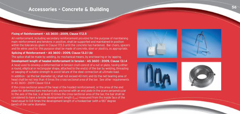
Development length of headed reinforcement in tension - as 3600 : 2009, clause 13.1.4A head used to develop a deformed bar in tension shall consist of a nut or plate, having either a round, elliptical or rectangular shape, attached to the end(s) of the bar by welding, threading or swaging of suitable strength to avoid failure of the steel connection at ultimate load.
In addition - (a) the bar diameter (db) shall not exceed 40 mm; and (b) the net bearing area of head shall be not less than 4 times the cross-sectional area of the bar. See other requirements in AS 3600 : 2009 Clause 13.1.4
If the cross-sectional area of the head of the headed reinforcement, or the area of the end plate for deformed bars mechanically anchored with an end plate in the plane perpendicular to the axis of the bar, is at least 10 times the cross-sectional area of the bar, the bar shall be considered to have a tensile development length (Lsy.t) measured from the inside face of the head equal to 0.8 times the development length of a hooked bar (with a 180˚degree bend) of the same diameter.
57
www.reinforcing.com | www.reinforcing.tv 57
accessoriesconcrete&building
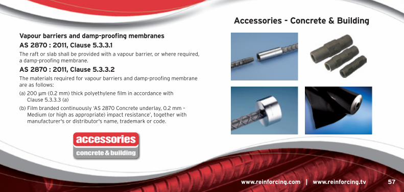
Vapour barriers and damp-proofing membranes
as 2870 : 2011, clause 5.3.3.1The raft or slab shall be provided with a vapour barrier, or where required, a damp-proofing membrane.
as 2870 : 2011, clause 5.3.3.2The materials required for vapour barriers and damp-proofing membrane are as follows:
(a) 200 μm (0.2 mm) thick polyethylene film in accordance with Clause 5.3.3.3 (a)
(b) Film branded continuously ‘AS 2870 Concrete underlay, 0.2 mm – Medium (or high as appropriate) impact resistance’, together with manufacturer's or distributor's name, trademark or code.
accessories - concrete & Building
58accessories - concrete & BuildingBlocKaiD©
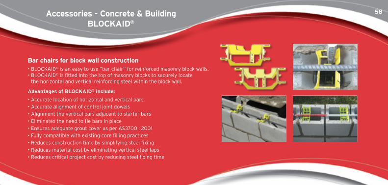
Bar chairs for block wall construction• BLOCKAID© is an easy to use “bar chair” for reinforced masonry block walls. • BLOCKAID© is fitted into the top of masonry blocks to securely locate
the horizontal and vertical reinforcing steel within the block wall.
advantages of BlocKaiD© include:
• Accurate location of horizontal and vertical bars• Accurate alignment of control joint dowels• Alignment the vertical bars adjacent to starter bars• Eliminates the need to tie bars in place• Ensures adequate grout cover as per AS3700 : 2001• Fully compatible with existing core filling practices• Reduces construction time by simplifying steel fixing• Reduces material cost by eliminating vertical steel laps• Reduces critical project cost by reducing steel fixing time
59
www.reinforcing.com | www.reinforcing.tv 59
ast.fsy - Product of reinforcing steel area (Ast),mm2 and reinforcement yield stress (fsy), MPa - gives nominal tensile capacity of a reinforcing bar - units generally kilo Newtons (kN) by dividing product by 1000.Band Beam - Wide beam with width significantly greater than depth, generally about 1200 to 2400 wide, used in buildings and carparks to minimuse structural floor depth. Either reinforced or post-tensioned concrete depending on the span and design loads.Beam - A narrow member in a building structure predominantly acting in flexure, generally horizontal.Bending moment - Internal action effect due to bending, normally resolved about a principal axis at a cross-section of a structural member.Bond strength - Normally expressed as the average ultimate stress that can develop at the interface between a bar and concrete when longitudinal slip occurs.500n contistREtch (cs) - 500 MPa low carbon bar : strength achieved by continuous stretching process.centre heave - Generally refers to deformation of a housing slab caused by the contraction of the expansive (clay) soils around the edge of a house - generally caused by drying out of the soils around house edge - opposite would be edge heave.column - A narrow vertical member in a building as distinct from a wall, normally under combined compression and bending.
compression - An internal state of compressive stress prependicular to a cross-section.compression member - A structural member predominantly in compression.cover - Minimum clear distance from an exposed concrete surface to closest bar - for durability design not just to main bars but to closest bar which is generally a stirrup or a tie. Insufficient cover is a major cause of reinforcement corrosion in concrete.creep - Property of concrete (dependant upon its constituents and internal state of stress) where a concrete element will deform due to sustained stress during its life. This is very important in the calculation of long-term deflections, and in prestressed/post-tensioned concrete design as an element can lose a significant proportion of its prestress.Decking - Profiled steel sheeting or structural steel decking used as a dual formwork, reinforcement system.Deflection - Normally the maximum vertical or horizonal movement of a structural member or a building frame, measured relative to the member supports or between adjacent floor levels in the case of sway.
Reinforced concrete thesaurus
60
Design load - The combination of factored loads (e.g. imposed, wind etc.) for the applicable limit state (e.g. serviceability, stability, strength, fire, etc.), assumed to be applied to a structural member or building.Detailing - Process whereby an engineer’s sketch is transformed into an engineering drawing - generally performed by a draftsman - this is then used by the reinforcing scheduler.Ductility (Reinforcement) - See Uniform Strain or Elongation.Ductility (member) - Ability of a member to deform under load - relevant to moment redistribution and especially important for seismic design of structures.Edge Beam - The beam around a floor perimeter, generally cast integrally with a concrete slab, which may form part of the beam flange.Edge heave - Generally refers to deformation of a housing slab caused by swelling of the expansive (clay) soils around the edge of a house - generally caused by excessive moisture around house edge - opposite would be centre heave.Edge Rebate - Notch cast in corner of beam - common in edge beam footing of brick veneer house to allow for brickwork to start below level of timber framing - done for aesthetic and waterproofing reasons.Elastic Design - When the design action effects associated with a redundant member of a building are computed assuming elastic behaviour of the steel and concrete, which affects the relative stiffnesses.
Embedment - The length of reinforcement measured past a critical section that is bonded to the concrete.finite Element analysis - A sophisticated form of numerical analysis traditionally used to model complex components or members acted on by different actions including temperature and increasingly being used to model whole 3-D concrete structures.flexural tensile strength - The maximum tensile stress reached in the extreme tensile fibre before the concrete cracks, normally measured in a small concrete beam test.in situ - In the actual position at the job site.lapping of mesh - The over-lapping of two or more adjacent sheets of mesh which is necessary in order to achieve continuity of the reinforcement.ligatures - General term for stirrups or ties - term more used in reinforcing manufacture than in design. Superseded by the general term “fitments” in AS 3600 : 2009.lightweight concrete - AS 3600 : 2009 defines lightweight concrete as “Concrete having a saturated surface-dry density in the range 1800 - 2100 kg/m3“.lintel - Beam type element generally supporting masonry over an opening. Can be concrete but more often than not is a steel angle.
Reinforced concrete thesaurus
61
www.reinforcing.com | www.reinforcing.tv 61
load factor - Factor by which a load is increased when computing design loads for the applicable limit state, e.g. serviceability, stability, strength, fire, etc).500n micRoalloY (ma) - 500 MPa bar : strength achieved by additions of alloying elements.modulus of Elasticity - Slope of elastic portion of stress/strain curve for a particular material, e.g. steel or concrete (same as Young’s modulus) - symbol generally E.moment Redistribution - In design, adjustment of the bending moment diagram at the strength limit state relative to the elastically-calculated design bending moment diagram and the actual distribution of design strength in bending, while maintaining equilibrium with the design loads.negative Bending moment - A bending moment that causes a tensile change in stress on the nearer face of a member, e.g. on the topside of a slab loaded from above.negative moment Region - Area of negative bending moment.negative Reinforcement - Main tensile reinforcement in a negative moment region.normal-Weight concrete - AS 3600 : 2009 defines normal-weight concrete as having a saturated surface-dry density in the range 2100 to 2800 kg/m3. Concrete density is usually assumed to be 2400 kg/m3.
Perimeter Edge footing - Edge beam around outside edge of house - may or may not be cast integrally with slab.Piles - Elements used to support a structure in poor soil/foundation conditions - based on the pile bearing on a good stratum at some distance below the structure to be supported - typically are steel, precast or cast in situ concrete - steel and precast used for long lengths and would be generally end bearing piles onto rock - cast in situ used for shorter length, and combination of end bearing onto a soil plus skin friction on the surrounding soil.Positive Bending moment - A bending moment that causes a tensile change in stress on the opposite face of a member. e.g. on the underside of a slab loaded from above.Positive Reinforcement - Main tensile reinforcement in a positive moment region of a horizontal member of a building. Post-tensioned concrete - Concrete elements where the concrete is poured with hollow ducts containing steel strand or bar subsequently stressed and normally grouted for bond. Extensively used in bridges, and beams and slabs of high-rise buildings. Strand has the ability to be “draped” (held towards the top of a member at the ends and towards the bottom of the member at mid-span) so as to induce an uplift force in the member. Strand is more suitable than bar where long lengths are required.
62
Precast concrete - Concrete elements that are cast in the factory or yard and lifted into position on site. Precast prestressed or post-tensioned beams for bridge construction are popular in Australia.Prestressed concrete - Generic term for any beam, slab or column containing stressed strands or bars - but normally refers to a concrete element cast around previously placed and stressed strand - just about all prestressed concrete is precast but not vice versa - main examples would be hollowcore planks - strands are stressed in long lengths, concrete poured, cured and set then strands cut - long members cut to required lengths - not to be confused with Post-Tensioned Concrete.Raft - Usually applied to slabs where the whole area of the slab is considered to act as a “raft” which relies on the underlying ground for support.Reinforcement surface condition - The state of the surface on the exterior of reinforcing bars. Note: hot-rolled bars normally have a thin layer of mill scale on the surface. Rust on the surface of reinforcement is not normally deleterious to the bond developed between the steel and concrete.shear Reinforcement - The reinforcement which caters for vertical or transverse shear forces in the member.shrinkage - Shortening of concrete due to autogenous shrinkage or drying shrinkage, which may be restrained in the direction of embedded steel, e.g. rebar, or by adjacent members or supports.
slump - Simple on-site measure of consistency (and possibly workability) of concrete in the as-mixed fluid state - involves a standard test using a metal cone.slipform - Form of construction used for building service cores, towers, etc - involves formwork moving continuously as concrete and reinforcement are placed.spacing of Reinforcement - The distance between adjacent reinforcing bars, normally measured centre-to-centre.stack cast - Flat slabs which are cast alternately, one on top of the other.starter Bars - Short reinforcing bars which are cast in or screwed into inserts at a joint to provide continuity of bending and shear strength across the joint.stiffness - Under flexural conditions, it is a function of EI/L - modulus of elasticity (normally of the concrete) (E) times effective second moment of area (l) of the composite uncracked and cracked sections divided by the length or span (L) of the element.stirrups - Same as ligatures. Generally provided in a beam as shear and torsional reinforcement (determined from engineering design) and hold t he main bars in position. Superseded by the general term "fitments" in AS3600 : 2009.
Reinforced concrete thesaurus
63
www.reinforcing.com | www.reinforcing.tv 63
strain - Ratio of elongation to original length. There are no units to strain.strain localisation - Uneven distribution of tensile strain in longitudinal steel reinforcement at flexural cracks due to bond transfer.strength - Used synonymously with capacity in Australian Standards, and can relate to axial force, shear force, bending moment, torsion, etc.stress - Local internal pressure that can arise due to action effects, restraint, etc. Units MPa or kPa.strip footing - Beam around the perimeter of a house, generally supporting a continuous line of masonry - generally not connected to the floor slab.tEmPcoRE® (tc) - Quenched and self-tempered straight length Grade 500 reinforcing bar.tensile Development length - A term in AS 3600 referring to the length of embedment of a straight reinforcing bar into concrete required to develop the yield stress of the reinforcement in axial tension. Related to bond stress (or strength).tensile strength - The maximum or ultimate tensile stress that can develop in a reinforcing bar, at which necking is initiated and fracture ensues.ties - Used in columns for various purposes including to prevent main bars from buckling at ultimate load should the cover spall - generally more closely spaced than stirrups in beams. See AS 3600 : 2009 for new rules concerning core-confinement for concrete >50 MPa and also new type of internal fitment with one leg. Superseded by the general term "fitments" in AS3600 : 2009.
tilt Up - Process of casting flat wall panels on the concrete floor on site and then lifting and securing in place using a mobile crane.torsion - Twisting of a building element (beam, slab, etc.) requiring additional reinforcement such as closed fitments in beams or additional corner bars in slabs. Ultimate strength Design - Design using the ultimate strength of materials to calculate the design strength of critical cross-sections or regions of concrete members which must exceed the ultimate design action effects.Uniform strain or Elongation - Axial strain of steel bar up to the point where the stress/strain curve starts to turn down (at the point of maximum load) - symbolised as Agt or εu and expressed as %.Yield strength - Alternative term for Yield Stress used in AS 3600.Yield stress - Stress at which steel yields, the definition of which depends on the shape of the stress-strain curve. In design, a lower characteristic value is used to define the strength grade of the steel.Young’s modulus - Slope of elastic portion of stress/strain curve (same as Modulus of Elasticity) - Symbol generally E for steel or concrete.
Reinforced concrete thesaurus
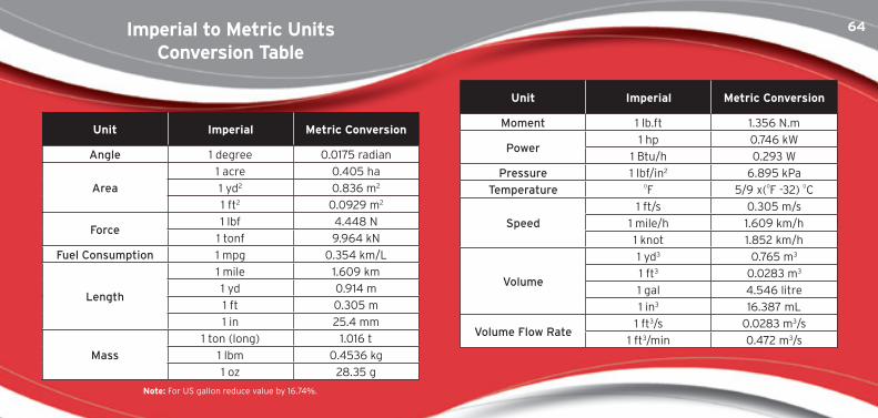
64imperial to metric Units conversion table
Unit imperial metric conversion
Moment 1 lb.ft 1.356 N.m
Power1 hp 0.746 kW
1 Btu/h 0.293 W
Pressure 1 lbf/in2 6.895 kPa
Temperature 0F 5/9 x(0F -32) 0C
Speed
1 ft/s 0.305 m/s
1 mile/h 1.609 km/h
1 knot 1.852 km/h
Volume
1 yd3 0.765 m3
1 ft3 0.0283 m3
1 gal 4.546 litre
1 in3 16.387 mL
Volume Flow Rate1 ft3/s 0.0283 m3/s
1 ft3/min 0.472 m3/s
Unit imperial metric conversion
Angle 1 degree 0.0175 radian
Area
1 acre 0.405 ha
1 yd2 0.836 m2
1 ft2 0.0929 m2
Force1 lbf 4.448 N
1 tonf 9.964 kN
Fuel Consumption 1 mpg 0.354 km/L
Length
1 mile 1.609 km
1 yd 0.914 m
1 ft 0.305 m
1 in 25.4 mm
Mass
1 ton (long) 1.016 t
1 lbm 0.4536 kg
1 oz 28.35 g
note: For US gallon reduce value by 16.74%.
65
www.reinforcing.com | www.reinforcing.tv 65
metric conversion kg/m3
Sand damp 1690
Sand wet 1840
Sandstone 1510
Shale 1250
Steel 7850
Top Soil 950
Water fresh 1000
Water salt 1030
Wood soft 480
Wood hard 800
metric conversion kg/m3
Granite 2600
Gravel mixed grading 1930
Ice 900
Lead 11370
Mercury 13570
Rockfill 75% rock, 25% earth 1960
Rockfill 50% rock, 25% earth 1720
Rockfill 25% rock, 75% earth 1570
Rubber 960-1300
Sand dry 1420
material kg/m3
Aluminium 2700
Brass 8400-8600
Cast Iron 7000-7400
Clay dry 1480
Clay wet 1660
Concrete 2400
Copper 8900
Earth dry 1280
Earth wet 1760
Glass 2400-2800
note: Figures for soils can vary greatly depending on moisture content, particle size and compaction. Figures provided are averages.
mass Densities of materials
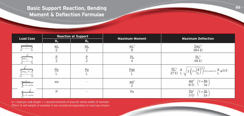
66Basic support Reaction, Bending moment & Deflection formulae
load caseReaction at support
maximum moment maximum DeflectionRa Rb
wL2
wL2
wL2
85wL4
384 EI
P2
P2
PL4
PL3
48 EI
PbL
PaL
PabL
PL3
27 EIaL
aL
aL
≤3 0.5which applies for1 _( ( ( (2 3
wa - wa2
2
wa4
8 EI4b3a
1 +( (P - Pa Pa3
3 EI3b2a
1 +( (w = load per unit length. I = second moment of area for whole width of member. Effect of self weight of member to be considered separately to load case shown.
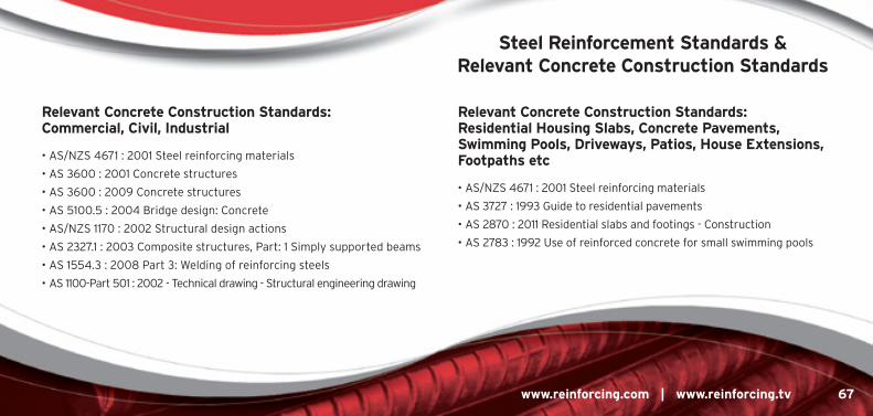
67
www.reinforcing.com | www.reinforcing.tv 67
Relevant concrete construction standards: commercial, civil, industrial
• AS/NZS 4671 : 2001 Steel reinforcing materials
• AS 3600 : 2001 Concrete structures
• AS 3600 : 2009 Concrete structures
• AS 5100.5 : 2004 Bridge design: Concrete
• AS/NZS 1170 : 2002 Structural design actions
• AS 2327.1 : 2003 Composite structures, Part: 1 Simply supported beams
• AS 1554.3 : 2008 Part 3: Welding of reinforcing steels
• AS 1100-Part 501 : 2002 - Technical drawing - Structural engineering drawing
Relevant concrete construction standards: Residential housing slabs, concrete Pavements, swimming Pools, Driveways, Patios, house Extensions, footpaths etc
• AS/NZS 4671 : 2001 Steel reinforcing materials
• AS 3727 : 1993 Guide to residential pavements
• AS 2870 : 2011 Residential slabs and footings - Construction
• AS 2783 : 1992 Use of reinforced concrete for small swimming pools
steel Reinforcement standards & Relevant concrete construction standards
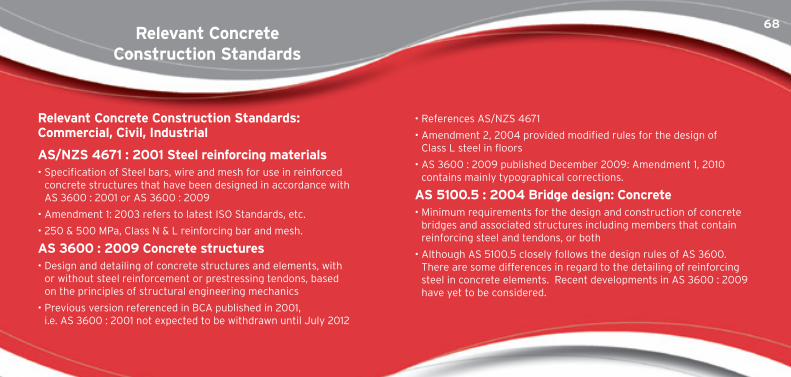
68
Relevant concrete construction standards: commercial, civil, industrial
as/nZs 4671 : 2001 steel reinforcing materials• Specification of Steel bars, wire and mesh for use in reinforced
concrete structures that have been designed in accordance with AS 3600 : 2001 or AS 3600 : 2009
• Amendment 1: 2003 refers to latest ISO Standards, etc.
• 250 & 500 MPa, Class N & L reinforcing bar and mesh.
as 3600 : 2009 concrete structures• Design and detailing of concrete structures and elements, with
or without steel reinforcement or prestressing tendons, based on the principles of structural engineering mechanics
• Previous version referenced in BCA published in 2001, i.e. AS 3600 : 2001 not expected to be withdrawn until July 2012
• References AS/NZS 4671
• Amendment 2, 2004 provided modified rules for the design of Class L steel in floors
• AS 3600 : 2009 published December 2009: Amendment 1, 2010 contains mainly typographical corrections.
as 5100.5 : 2004 Bridge design: concrete• Minimum requirements for the design and construction of concrete
bridges and associated structures including members that contain reinforcing steel and tendons, or both
• Although AS 5100.5 closely follows the design rules of AS 3600. There are some differences in regard to the detailing of reinforcing steel in concrete elements. Recent developments in AS 3600 : 2009 have yet to be considered.
Relevant concrete construction standards
69
www.reinforcing.com | www.reinforcing.tv 69
as/nZs 1170 : 2002 structural design actionsPart 1: Permanent, imposed and other actions (loading code)
• Specifies permanent, imposed, static liquid pressure, ground water, rainwater ponding and earth pressure actions to be used in the limit state design of structures and parts of structures
• Ref AS/NZS 1170 - Loading Standards
• Amendments 1 & 4 - April 2005
as 2327.1 : 2003 - composite structuresPart 1: simply supported beams
• Sets out minimum requirements for the design, detailing and construction of simply supported composite beams composed of a steel beam and a concrete slab interconnected with shear connectors, including applications where the slab incorporates profiled steel sheeting.
• The main changes are related to the design of shear connectors, stud location, distinction between open and closed rib profiles, 500 MPa longitudinal shear reinforcement and some new reference material.
as 1554.3 : 2008 Part 3: Welding of reinforcing steels
• The welding of reinforcing steel used in concrete structures that are designed and constructed in accordance with AS 3600
• Reference: AS/NZS 4671
as 110o-Part 501 : 2002 - technical drawing - structural engineering drawing• This Standard references AS/NZS 4671 : 2001 and thus covers the
use of 500 MPa reinforcing bar and mesh.
Relevant Residential concrete construction standards
70
Relevant concrete construction standards: Residential housing slabs, concrete Pavements, Pools, Driveways, Patios, house Extensions, footpaths, etc
as/nZs 4671 : 2001 steel reinforcing materials• Specification of steel bars, wire and mesh for use in reinforced
concrete structures that have been designed in accordance with AS 3600 : 2001 or AS 3600 : 2009
• 250 & 500 MPa. Class N & L reinforcing bar and mesh
• Supersedes AS 1302, 1303 & 1304. Amendment - 1 June 2003
as 3727 : 1993 Guide to residential pavements• Guidelines for the selection and construction of pavements
associated with residential buildings consisting of single houses or multiple dwellings in medium density housing development
• Recommends mesh sizes for concrete slabs, depending on the service requirements
• Loading categories - foot traffic, light and medium vehicles, as well as joint spacing
as 2870 : 2011 Residential slabs and footings – construction• This standard covers slab on ground for housing
• Classification of a site and the design and construction of a footing system for a single dwelling house, townhouse or the like which may be detached or separated by a party wall or common wall, but not situated vertically above or below another dwelling
• Treats Class N and L reinforcing steels as fully equivalent to each other as main or secondary reinforcement
• Previous version referenced in BCA published in 2001, i.e. AS 2870 : 1996
as 2783 : 1992 Use of reinforced concrete for small swimming pools• Structural design and construction of reinforced concrete pools
• References AS 3600 & AS 3735 - Concrete structures for retaining liquids
71
www.reinforcing.com | www.reinforcing.tv 71
compliance to concrete construction standards
Does reinforcing bar and mesh comply with australian standards?• Commercial buildings, bridges, civil structures, house slabs, patios,
extensions, driveways, footpaths, etc, must be built with steel reinforcement with the correct chemical and mechanical properties.
• Not all rebar and reomesh meets Australian Standards. Materials are sourced widely in Australia and from overseas, and manufactured to varying standards, so you need to check and be sure of what you are getting or specifying.
• There are potentially serious consequences of using non-compliant materials. For example: serviceability (excessive cracking or deflections due to poor bond); ultimate (reduced strength and safety due to low yield stress or inadequate ductility).
• Australian Standards require steel reinforcement to have the necessary chemical and mechanical properties, strength and level of ductility appropriate to the engineering design assumptions on which they are based.
• The Building Code of Australia (BCA) references Australian Standards. ACRS certified steel reinforcing materials comply with the relevant Australian Standards and therefore the BCA.
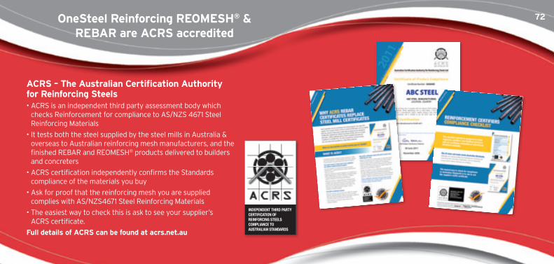
72onesteel Reinforcing REomEsh® & REBaR are acRs accredited
acRs – the australian certification authority for Reinforcing steels• ACRS is an independent third party assessment body which
checks Reinforcement for compliance to AS/NZS 4671 Steel Reinforcing Materials
• It tests both the steel supplied by the steel mills in Australia & overseas to Australian reinforcing mesh manufacturers, and the finished REBAR and REOMESH® products delivered to builders and concreters
• ACRS certification independently confirms the Standards compliance of the materials you buy
• Ask for proof that the reinforcing mesh you are supplied complies with AS/NZS4671 Steel Reinforcing Materials
• The easiest way to check this is ask to see your supplier’s ACRS certificate.
full details of acRs can be found at acrs.net.au
73
www.reinforcing.com | www.reinforcing.tv 73
steel Reinforcement institute of australia (sRia) technical notes
OneSteel Reinforcing is proud to be a member of the SRIA. The following Technical Notes are available for download from the SRIA website.
technical note 1: Surface Condition of Steel Reinforcement
technical note 2: Substitution of N12 Rebar in AS 2870 Residential Slabs & Footings
technical note 3: Restrictions on the Use of Wire Bar Chairs
technical note 4: Fabrication and Site Handling of Reinforcing Bars
technical note 5: Guidelines for Economical Assembly of Reinforcement
technical note 6: Design to AS 3600 : 2001 of Suspended Concrete Floors Reinforced with Class L Mesh
www.sria.com.au
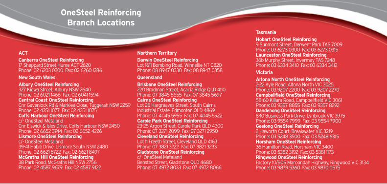
74onesteel Reinforcing Branch locations
actcanberra onesteel Reinforcing17 Sheppard Street Hume ACT 2620Phone: 02 6203 0200 Fax: 02 6260 1286new south Walesalbury onesteel Reinforcing327 Kiewa Street, Albury NSW 2640Phone: 02 6021 1466 Fax: 02 6041 1594 central coast onesteel ReinforcingCnr Gavenlock Rd & Marklea Close, Tuggerah NSW 2259 Phone: 02 4351 1077 Fax: 02 4351 1075coffs harbour onesteel Reinforcing c/- OneSteel MetalandCnr Elswick & Isles Drive, Coffs Harbour NSW 2450 Phone: 02 6652 3744 Fax: 02 6652 4226 lismore onesteel Reinforcing c/- OneSteel Metaland39-41 Habib Drive, Lismore South NSW 2480Phone: 02 6621 8722 Fax: 02 6621 8497mcGraths hill onesteel Reinforcing38 Park Road, McGraths Hill NSW 2756 Phone: 02 4587 9679 Fax: 02 4587 9122
northern territoryDarwin onesteel ReinforcingLot 1611 Bombing Road, Winnellie NT 0820Phone: 08 8947 0330 Fax: 08 8947 0358QueenslandBrisbane onesteel Reinforcing 220 Bradman Street, Acacia Ridge QLD 4110Phone: 07 3845 5655 Fax: 07 3845 5697cairns onesteel Reinforcing Lot 25 Hargreaves Street, South Cairns Industrial Estate, Edmonton QLD 4869Phone: 07 4045 5955 Fax: 07 4045 5922carole Park onesteel Reinforcing23-25 Argon Street, Carole Park QLD 4300Phone: 07 3271 2099 Fax: 07 3271 2950 cleveland onesteel ReinforcingLot 11 Freeth Street, Cleveland QLD 4163 Phone: 07 3821 3222 Fax: 07 3821 3233Gladstone onesteel Reinforcing c/- OneSteel MetalandBensted Street, Gladstone QLD 4680Phone: 07 4972 8033 Fax: 07 4972 8066
tasmaniahobart onesteel Reinforcing9 Sunmont Street, Derwent Park TAS 7009Phone: 03 6273 0300 Fax: 03 6273 0315launceston onesteel Reinforcing36b Murphy Street, Invermay TAS 7248Phone: 03 6334 3410 Fax: 03 6334 3412Victoriaaltona north onesteel Reinforcing2-22 Kyle Road, Altona North VIC 3025Phone: 03 9207 2200 Fax: 03 9207 2270campbellfield onesteel Reinforcing58-60 Killara Road, Campbellfield VIC 3061Phone: 03 9357 8855 Fax: 03 9357 8292Dandenong onesteel Reinforcing6-10 Business Park Drive, Lynbrook VIC 3975Phone: 03 9554 7999 Fax: 03 9554 7900Geelong onesteel Reinforcing2 Haworth Court, Breakwater VIC 3219Phone: 03 5248 3500 Fax: 03 5248 6315horsham onesteel Reinforcing36 Hamilton Road, Horsham VIC 3400Phone: 03 5382 3192 Fax: 03 5381 1173Ringwood onesteel ReinforcingFactory 10/505 Maroondah Highway, Ringwood VIC 3134Phone: 03 9879 5360 Fax: 03 9870 0575
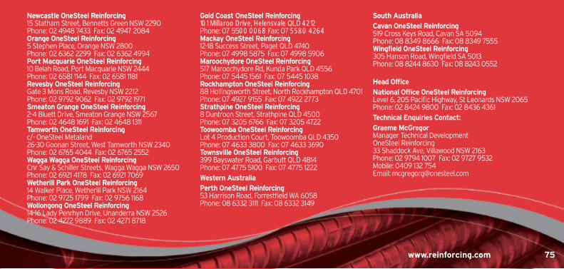
75
www.reinforcing.com | www.reinforcing.tv 75www.reinforcing.com 75
newcastle onesteel Reinforcing15 Statham Street, Bennetts Green NSW 2290Phone: 02 4948 7433 Fax: 02 4947 2084orange onesteel Reinforcing5 Stephen Place, Orange NSW 2800Phone: 02 6362 2299 Fax: 02 6362 4994Port macquarie onesteel Reinforcing10 Belah Road, Port Macquarie NSW 2444 Phone: 02 6581 1144 Fax: 02 6581 1181Revesby onesteel ReinforcingGate 3 Mons Road, Revesby NSW 2212 Phone: 02 9792 9062 Fax: 02 9792 1971smeaton Grange onesteel Reinforcing2-4 Bluett Drive, Smeaton Grange NSW 2567 Phone: 02 4648 1691 Fax: 02 4648 1311tamworth onesteel Reinforcing c/- OneSteel Metaland26-30 Goonan Street, West Tamworth NSW 2340Phone: 02 6765 4044 Fax: 02 6765 2552Wagga Wagga onesteel ReinforcingCnr Say & Schiller Streets, Wagga Wagga NSW 2650 Phone: 02 6921 4178 Fax: 02 6921 7069Wetherill Park onesteel Reinforcing14 Walker Place, Wetherill Park NSW 2164Phone: 02 9725 1799 Fax: 02 9756 1168Wollongong onesteel Reinforcing14-16 Lady Penrhyn Drive, Unanderra NSW 2526Phone: 02 4272 9889 Fax: 02 4271 8718
Gold coast onesteel Reinforcing101 Millaroo Drive, Helensvale QLD 4212Phone: 07 5500 0068 Fax: 07 5580 4264mackay onesteel Reinforcing12-18 Success Street, Paget QLD 4740 Phone: 07 4998 5875 Fax: 07 4998 5906maroochydore onesteel Reinforcing517 Maroochydore Rd, Kunda Park QLD 4556 Phone: 07 5445 1561 Fax: 07 5445 1038Rockhampton onesteel Reinforcing88 Hollingsworth Street, North Rockhampton QLD 4701Phone: 07 4927 9155 Fax: 07 4922 2773strathpine onesteel Reinforcing8 Duntroon Street, Strathpine QLD 4500Phone: 07 3205 6766 Fax: 07 3205 4722toowoomba onesteel ReinforcingLot 4 Production Court, Toowoomba QLD 4350 Phone: 07 4633 3800 Fax: 07 4633 3690townsville onesteel Reinforcing399 Bayswater Road, Garbutt QLD 4814Phone: 07 4775 5100 Fax: 07 4775 1222Western australiaPerth onesteel Reinforcing53 Harrison Road, Forrestfield WA 6058Phone: 08 6332 3111 Fax: 08 6332 3149
south australiacavan onesteel Reinforcing519 Cross Keys Road, Cavan SA 5094Phone: 08 8349 8666 Fax: 08 8349 7555Wingfield onesteel Reinforcing305 Hanson Road, Wingfield SA 5013Phone: 08 8244 8630 Fax: 08 8243 0552
head officenational office onesteel ReinforcingLevel 6, 205 Pacific Highway, St Leonards NSW 2065Phone: 02 8424 9800 Fax: 02 8436 4361technical Enquiries contact:Graeme mcGregorManager Technical DevelopmentOneSteel Reinforcing33 Shaddock Ave, Villawood NSW 2163Phone: 02 9794 1007 Fax: 02 9727 9532Mobile: 0409 132 754Email: [email protected]
CM1234567891011121314151617181920
REINV
ENTING
R
EINFORCIN
G
www.reinforcing.co
m
www.re
inforcing. tv
• This information is provided as a service to those interested in steel reinforcement. Since the information is provided for general guidance only, and in no way replaces the services of professional consultants on particular projects or subjects, no legal liability can be accepted by OneSteel Reinforcing Pty Limited for its use
• Not all products are available in all locations. We reserve the right to amend specifications without notice
• 500PLUS REIDBAR, 500PLUS REBAR, 500PLUS ADVANCED DESIGN, ONEMESH, UTEMESH, REOMESH®, TRUSSDEK, BAMTEC, ONESLAB, POOLSTEEL, IRONBARK, HANDIMESH, ROMTECH, FIBRESTEEL, FIBRECRETE, MINEMESH, REODATA, TEMPCORE, ECO-REO, ECO-MESH and ECO-BAR are trademarks authorised for use by OneSteel Reinforcing Pty Limited ABN 22 004 148 289
• OneSteel Reinforcing REBAR and REOMESH® products are independently certified by ACRS the Australian Certification Authority for Reinforcing Steels to confirm compliance to Australian Standards
• Supporting information on environmental claims for specific OneSteel Reinforcing ECO-REO™ products is on the Technical Resources page of the OneSteel Reinforcing website www.reinforcing.com
National Office: Level 6, 205 Pacific Hwy, St Leonards NSW 2065 Locked Bag 3050, Artarmon NSW 1570 Telephone: (61 2) 8424 9800
Facsimile: (61 2) 8436 4361 Email: [email protected]
www.reinforcing.com | www.reinforcing.tv
Build with OneSteel Reinforcing
©O
SR0
669
REO
DA
TA 4
.0
Related Documents