Renault ALASKAN Vehicle user manual

Welcome message from author
This document is posted to help you gain knowledge. Please leave a comment to let me know what you think about it! Share it to your friends and learn new things together.
Transcript

Renault ALASKANVehicle user manual
RENAULT S.A.S. SOCIÉTÉ PAR ACTIONS SIMPLIFIÉE AU CAPITAL DE 533 941 113 € - 13-15, QUAI LE GALLO
92100 BOULOGNE-BILLANCOURT R.C.S. NANTERRE 780 129 987 — SIRET 780 129 987 03591 - TÉL. : 0810 40 50 60
Printing: November 2020 (01) / Publication Number: OM20EN-0U60E1EUR / Part Number: 7711413295--- / Printed in France
U60
EN

Castrol, exclusive Renault partner
Renault recommends
Castrol, exclusive Renault partner
Benefit from cutting-edge technology born out of competition to ensure the performance and longevity ofyour Renault thanks to wide range of engine lubricants developed specially by Renault and Castrol.
Renault recommends
renault.com
U60
EN
U60
EN
ForewordThis handbook was prepared to help you understand the operation and maintenance of your vehicle so that you may enjoy many kilometres (miles) of driving plea-sure. Please read through this handbook before operating your vehicle.
A separate Warranty Information & Maintenance Booklet explains in detail the warranty coverage that applies to your vehicle.
Your approved dealer knows your vehicle best. When you require any service or have any questions, your approved dealer will be glad to assist you with the exten-sive resources available for you.
IMPORTANT SAFETY INFORMATION REMINDERS!Follow these important driving rules to help ensure a safe and complete trip foryou and your passengers!
• NEVER drive under the influence of alcohol or drugs.
• ALWAYS observe posted speed limits and never drive too fast for condi-tions.
• ALWAYS give your full attention to driving and avoid using vehicle fea-tures or taking other actions that could distract you.
• ALWAYS use your seat belts and appropriate child restraint systems. Pre-teen children should be seated in the rear seat.
• ALWAYS provide information about the proper use of vehicle safety fea-tures to all occupants of the vehicle.
• ALWAYS review this Driver's handbook for important safety information.
WHEN READING THE HANDBOOKThis handbook includes information for all options available on this model.Therefore, you may find some information that does not apply to your vehicle.
Throughout this handbook, some illustrations may only show the layout forLeft-Hand Drive (LHD) models. For Right-Hand Drive (RHD) models, the illus-trated shape and location of some components may differ.
All information, specifications and illustrations in this handbook are those ineffect at the time of printing. RENAULT reserves the right to change specifica-tions or designs at any time without notice and without obligation.
MODIFICATION OF YOUR VEHICLEThis vehicle cannot be modified without taking into consideration the RENAULT“Bodybuilders Standards for Assembly, Equipment and Conversion” that hasbeen written for this purpose. All modifications done which do not follow theinstructions in that document could affect the vehicle functioning and its life-time. Furthermore, failure to comply with these Standards may arise in securityproblems and could even result in prosecution. Damages or failures in the ve-hicle as a consequence of modifications may not be covered under RENAULTwarranty.
READ FIRST — THEN DRIVE SAFELYBefore driving your vehicle, read this Driver's handbook carefully. This will en-sure familiarity with controls and maintenance requirements, assisting you inthe safe operation of your vehicle.
Throughout this handbook the following symbols and words are used:
WARNINGIndicates the presence of a hazard that could cause death or serious per-sonal injury. To avoid or reduce the risk, the procedures described must befollowed precisely.
CAUTIONIndicates the presence of a hazard that could cause minor or moderate per-sonal injury, or damage to your vehicle. To avoid or reduce the risk, the pro-cedures described must be followed carefully.
NOTE
Indicates additional helpful information.
This symbol means “Do not do this” or “Do not let this happen”.
Arrows in an illustration that are similar to these point to the front of the vehicle.
Arrows in an illustration that are similar to these indicate movement or action.
Arrows in an illustration that are similar to these call attention to an item in theillustration.
[ ]:
Square brackets are used to indicate messages, keys, or items displayed on ascreen.
< >:
Chevrons or angle brackets are used to indicate texts on controls like buttonsor switches inside or on the vehicle.
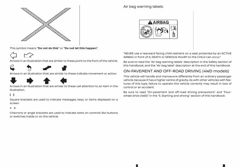
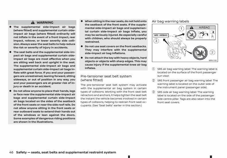
Air bag warning labels:
“NEVER use a rearward facing child restraint on a seat protected by an ACTIVEAIRBAG in front of it, DEATH or SERIOUS INJURY to the CHILD can occur.”
Be sure to read the “Air bag warning labels” description in the Safety section ofthis handbook; and the “Air bag label” description at the end of this handbook.
ON-PAVEMENT AND OFF-ROAD DRIVING (4WD models)This vehicle will handle and manoeuvre differently from an ordinary passengervehicle, because it has a higher centre of gravity. As with other vehicles with fea-tures of this type, failure to operate this vehicle correctly may result in loss ofcontrol or an accident.
Be sure to read “On-pavement and off-road driving precautions” and “Four-wheel drive (4WD)” in the “5. Starting and driving” section of this handbook.
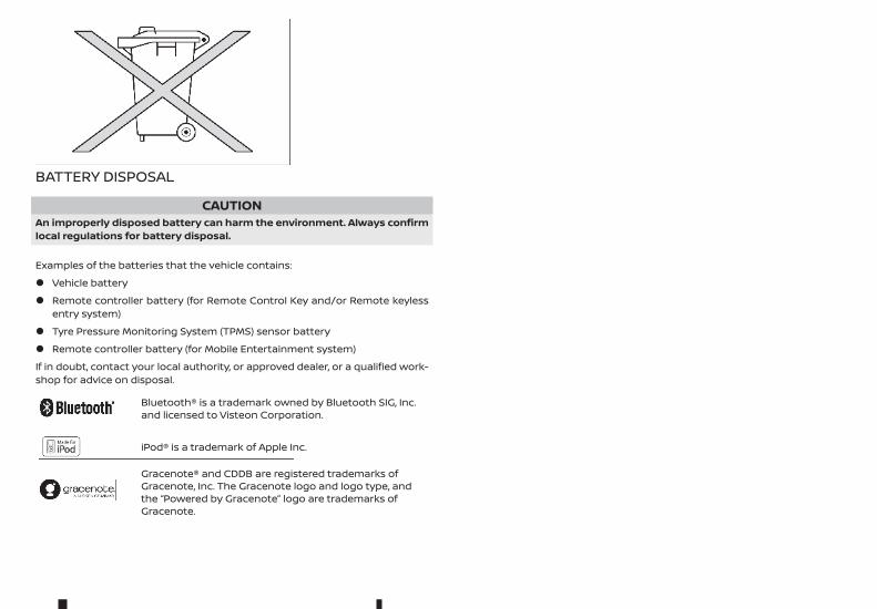
BATTERY DISPOSAL
CAUTIONAn improperly disposed battery can harm the environment. Always confirmlocal regulations for battery disposal.
Examples of the batteries that the vehicle contains:
• Vehicle battery
• Remote controller battery (for Remote Control Key and/or Remote keylessentry system)
• Tyre Pressure Monitoring System (TPMS) sensor battery
• Remote controller battery (for Mobile Entertainment system)
If in doubt, contact your local authority, or approved dealer, or a qualified work-shop for advice on disposal.
mBluetooth® is a trademark owned by Bluetooth SIG, Inc.and licensed to Visteon Corporation.
miPod® is a trademark of Apple Inc.
mGracenote® and CDDB are registered trademarks ofGracenote, Inc. The Gracenote logo and logo type, andthe “Powered by Gracenote” logo are trademarks ofGracenote.

Contents Illustrated table of contents 0Safety — seats, seat belts and supplementalrestraint system 1
Instruments and controls 2
Pre-driving checks and adjustments 3Display screen, heater and air conditioner, and audiosystem 4
Starting and driving 5
In case of emergency 6
Appearance and care 7
Maintenance and do-it-yourself 8
Technical information 9
Index 10

0 Illustrated table of contentsIllustrated table of contents
Seats, seat belts and Supplemental RestraintSystem (SRS).................................................................................................... 2Exterior front ................................................................................................... 3Exterior rear ..................................................................................................... 4Passenger compartment....................................................................... 5Cockpit................................................................................................................. 6
Left-Hand Drive (LHD) model ...................................................... 6
Right-Hand Drive (RHD) model .................................................. 7Instrument panel ......................................................................................... 8
Left-Hand Drive (LHD) model ...................................................... 8Right-Hand Drive (RHD) model .................................................. 9
Meters and gauges..................................................................................... 10Engine compartment ............................................................................... 11
M9T 2.3DCI engine .............................................................................. 11
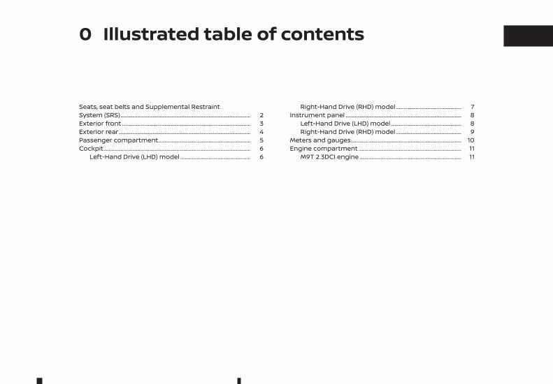
1. Supplemental front-impact air bags* (P. 1-42)
2. Front passenger air bag switch* (P. 1-50)
3. Supplemental curtain side-impact air bags*(P. 1-42)
4. Seat belts (P. 1-21)
5. Head restraints (P. 1-18)
6. Child restraint anchor point* (for top tetherstrap child restraint) (P. 1-33)
7. Rear seats* (P. 1-17)
8. Supplemental side-impact air bags* (P. 1-42)
9. Pre-tensioner seat belt system* (P. 1-46)
10. Front seats (P. 1-14)
11. Supplemental driver's knee air bag* (P. 1-42)
*: where fitted
NIC2797
SEATS, SEAT BELTS AND SUPPLEMENTAL RESTRAINT SYSTEM (SRS)
2 Illustrated table of contents
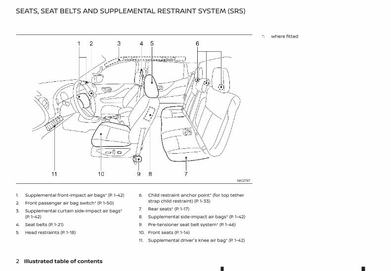
1. Bonnet (P. 3-111)
2. Windscreen wipers and washers— Switch operation (P. 2-81)— Wiper blade replacement (P. 8-279)— Window washer fluid (P. 8-274)
3. Sunroof*1 (P. 2-89)
4. Windows (P. 2-84)
5. Roof rail*1 (P. 2-88)
6. Child safety rear door locks*1 (P. 3-99)
7. Doors— Keys (P. 3-96)— Door locks (P. 3-98)— Remote keyless entry system*1 (P. 3-99)— Remote Control Key system*1 (P. 3-101)— Security system*1 (P. 3-110)
8. Outside rearview mirrors (P. 3-120)
9. Side turn signal lights— Bulb replacement (P. 8-287)
10. Tyres— Tyres and wheels (P. 8-290)— Flat tyre (P. 6-240)— Specifications (P. 9-296)— Four-Wheel Drive (4WD)*1 (P. 5-218)
11. Headlights and turn signal lights— Switch operation (P. 2-78)— Bulb replacement (P. 8-285)
12. Headlight cleaner*1— Operation (P. 2-83)
13. Front fog lights*1 or Daytime running lights*1— Switch operation (P. 2-80, P. 2-79)— Bulb replacement (P. 8-287)
14. Towing eye*2 (P. 6-254)
*1: where fitted
*2: The layout illustrated is for the Right-HandDrive (RHD) model. On the Left-Hand Drive(LHD) model, the towing eye is located on theopposite side.
NIC3080
EXTERIOR FRONT
Illustrated table of contents 3
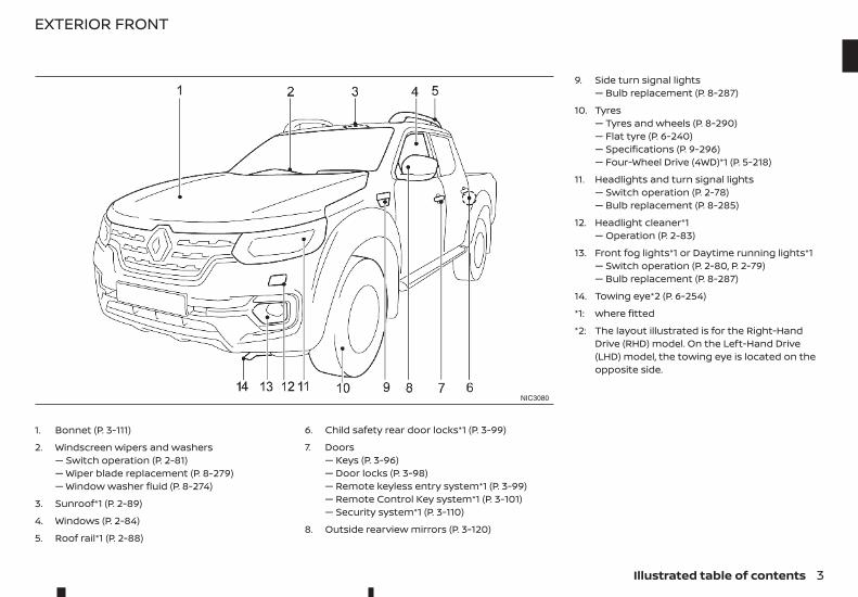
1. Rear window defogger* (P. 2-82)
2. High-mounted stop light* (P. 5-235)
3. Antenna* (P. 4-150)
4. AdBlue filler lid (P. 3-114)
5. Rear view camera*— Reversing camera* (P. 4-124)
6. Cargo bed* (P. 3-115)
7. Rear combination lights (bulb replacement)(P. 8-287)
8. Number plate lights (bulb replacement)(P. 8-287)
9. Parking sensor (sonar)* (P. 5-231)
*: where fitted
NIC3081
EXTERIOR REAR
4 Illustrated table of contents
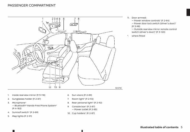
1. Inside rearview mirror (P. 3-118)
2. Sunglasses holder (P. 2-87)
3. Microphone*— Bluetooth® Hands-Free Phone System*(P. 4-182)
4. Sunroof switch* (P. 2-89)
5. Map lights (P. 2-91)
6. Sun visors (P. 2-89)
7. Room light* (P. 2-92)
8. Rear personal light* (P. 2-92)
9. Console box* (P. 2-87)— Power outlet (P. 2-85)
10. Cup holders* (P. 2-87)
11. Door armrest— Power window controls* (P. 2-84)— Power door lock switch (driver's door)*(P. 3-98)— Outside rearview mirror remote controlswitch (driver's door)* (P. 3-120)
*: where fitted
NIC2792
PASSENGER COMPARTMENT
Illustrated table of contents 5
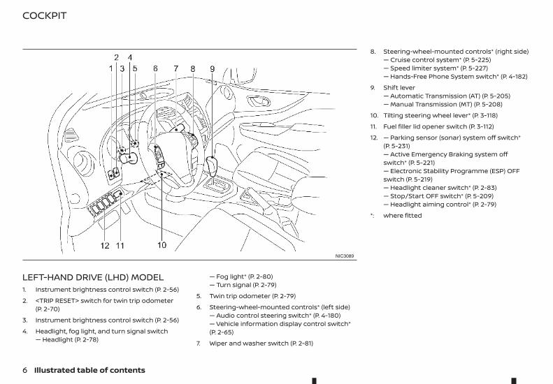
LEFT-HAND DRIVE (LHD) MODEL1. Instrument brightness control switch (P. 2-56)
2. <TRIP RESET> switch for twin trip odometer(P. 2-70)
3. Instrument brightness control switch (P. 2-56)
4. Headlight, fog light, and turn signal switch— Headlight (P. 2-78)
— Fog light* (P. 2-80)— Turn signal (P. 2-79)
5. Twin trip odometer (P. 2-79)
6. Steering-wheel-mounted controls* (left side)— Audio control steering switch* (P. 4-180)— Vehicle information display control switch*(P. 2-65)
7. Wiper and washer switch (P. 2-81)
8. Steering-wheel-mounted controls* (right side)— Cruise control system* (P. 5-225)— Speed limiter system* (P. 5-227)— Hands-Free Phone System switch* (P. 4-182)
9. Shift lever— Automatic Transmission (AT) (P. 5-205)— Manual Transmission (MT) (P. 5-208)
10. Tilting steering wheel lever* (P. 3-118)
11. Fuel filler lid opener switch (P. 3-112)
12. — Parking sensor (sonar) system off switch*(P. 5-231)— Active Emergency Braking system offswitch* (P. 5-221)— Electronic Stability Programme (ESP) OFFswitch (P. 5-219)— Headlight cleaner switch* (P. 2-83)— Stop/Start OFF switch* (P. 5-209)— Headlight aiming control* (P. 2-79)
*: where fitted
NIC3089
COCKPIT
6 Illustrated table of contents
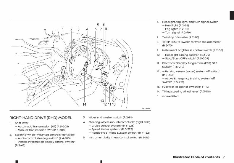
RIGHT-HAND DRIVE (RHD) MODEL1. Shift lever
— Automatic Transmission (AT) (P. 5-205)— Manual Transmission (MT) (P. 5-208)
2. Steering-wheel-mounted controls* (left side)— Audio control steering switch* (P. 4-180)— Vehicle information display control switch*(P. 2-65)
3. Wiper and washer switch (P. 2-81)
4. Steering-wheel-mounted controls* (right side)— Cruise control system* (P. 5-225)— Speed limiter system* (P. 5-227)— Hands-Free Phone System switch* (P. 4-182)
5. Instrument brightness control switch (P. 2-56)
6. Headlight, fog light, and turn signal switch— Headlight (P. 2-78)— Fog light* (P. 2-80)— Turn signal (P. 2-79)
7. Twin trip odometer (P. 2-70)
8. <TRIP RESET> switch for twin trip odometer(P. 2-70)
9. Instrument brightness control switch (P. 2-56)
10. — Headlight aiming control* (P. 2-79)— Stop/Start OFF switch* (P. 5-209)
11. Electronic Stability Programme (ESP) OFFswitch* (P. 5-219)
12. — Parking sensor (sonar) system off switch*(P. 5-231)— Active Emergency Braking system offswitch* (P. 5-221)
13. Fuel filler lid opener switch (P. 3-112)
14. Tilting steering wheel lever* (P. 3-118)
*: where fitted
NIC3090
Illustrated table of contents 7
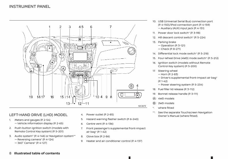
LEFT-HAND DRIVE (LHD) MODEL1. Meters and gauges (P. 2-54)
— Vehicle information display (P. 2-65)
2. Push-button ignition switch (models withRemote Control Key system) (P. 5-201)
3. Audio system* (P. 4-146) or Navigation system**— Reversing camera* (P. 4-124)— 360° Camera* (P. 4-127)
4. Power outlet (P. 2-85)
5. Hazard warning flasher switch (P. 6-240)
6. Centre vent (P. 4-136)
7. Front passenger’s supplemental front-impactair bag* (P. 1-42)
8. Glove box (P. 2-86)
9. Heater and air conditioner control (P. 4-137)
10. USB (Universal Serial Bus) connection port(P. 4-150)/iPod connection port (P. 4-159)— Auxiliary (AUX) input jack (P. 4-151)
11. Power door lock switch* (P. 3-98)
12. Hill descent control switch* (P. 5-224)
13. Parking brake— Operation (P. 3-121)— Check (P. 8-271)
14. Differential lock mode switch* (P. 5-218)
15. Four-Wheel Drive (4WD) mode switch* (P. 5-212)
16. Ignition switch (models without RemoteControl Key system) (P. 5-200)
17. Steering wheel— Horn (P. 2-83)— Driver’s supplemental front-impact air bag*(P. 1-42)— Power steering system (P. 5-234)
18. Fuel filler lid release (P. 3-112)
19. Bonnet release handle (P. 3-111)jA : 4WD modelsjB : 2WD models
*: where fitted
**: See the separate Touchscreen NavigationOwner's Manual (where fitted).
NIC3679
INSTRUMENT PANEL
8 Illustrated table of contents
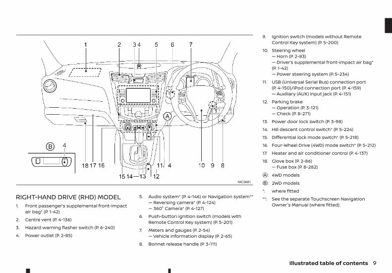
RIGHT-HAND DRIVE (RHD) MODEL1. Front passenger’s supplemental front-impact
air bag* (P. 1-42)
2. Centre vent (P. 4-136)
3. Hazard warning flasher switch (P. 6-240)
4. Power outlet (P. 2-85)
5. Audio system* (P. 4-146) or Navigation system**— Reversing camera* (P. 4-124)— 360° Camera* (P. 4-127)
6. Push-button ignition switch (models withRemote Control Key system) (P. 5-201)
7. Meters and gauges (P. 2-54)— Vehicle information display (P. 2-65)
8. Bonnet release handle (P. 3-111)
9. Ignition switch (models without RemoteControl Key system) (P. 5-200)
10. Steering wheel— Horn (P. 2-83)— Driver’s supplemental front-impact air bag*(P. 1-42)— Power steering system (P. 5-234)
11. USB (Universal Serial Bus) connection port(P. 4-150)/iPod connection port (P. 4-159)— Auxiliary (AUX) input jack (P. 4-151)
12. Parking brake— Operation (P. 3-121)— Check (P. 8-271)
13. Power door lock switch (P. 3-98)
14. Hill descent control switch* (P. 5-224)
15. Differential lock mode switch* (P. 5-218)
16. Four-Wheel Drive (4WD) mode switch* (P. 5-212)
17. Heater and air conditioner control (P. 4-137)
18. Glove box (P. 2-86)— Fuse box (P. 8-282)
jA : 4WD modelsjB : 2WD models
*: where fitted
**: See the separate Touchscreen NavigationOwner's Manual (where fitted).
NIC3681
Illustrated table of contents 9
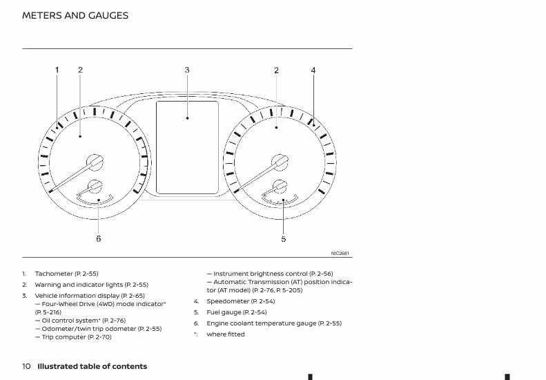
1. Tachometer (P. 2-55)
2. Warning and indicator lights (P. 2-55)
3. Vehicle information display (P. 2-65)— Four-Wheel Drive (4WD) mode indicator*(P. 5-216)— Oil control system* (P. 2-76)— Odometer/twin trip odometer (P. 2-55)— Trip computer (P. 2-70)
— Instrument brightness control (P. 2-56)— Automatic Transmission (AT) position indica-tor (AT model) (P. 2-76, P. 5-205)
4. Speedometer (P. 2-54)
5. Fuel gauge (P. 2-54)
6. Engine coolant temperature gauge (P. 2-55)
*: where fitted
NIC2681
METERS AND GAUGES
10 Illustrated table of contents
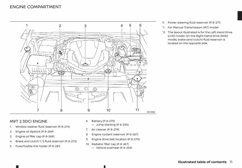
M9T 2.3DCI ENGINE1. Window washer fluid reservoir (P. 8-274)
2. Engine oil dipstick (P. 8-269)
3. Engine oil filler cap (P. 8-269)
4. Brake and clutch*1,*2 fluid reservoir (P. 8-272)
5. Fuse/fusible link holder (P. 8-281)
6. Battery (P. 8-275)— Jump starting (P. 6-250)
7. Air cleaner (P. 8-279)
8. Engine coolant reservoir (P. 8-267)
9. Engine drive belt location (P. 8-270)
10. Radiator filler cap (P. 8-267)— Vehicle overheat (P. 6-253)
11. Power steering fluid reservoir (P. 8-271)
*1: For Manual Transmission (MT) model
*2: The layout illustrated is for the Left-Hand Drive(LHD) model. On the Right-Hand Drive (RHD)model, brake (and clutch) fluid reservoir islocated on the opposite side.
NIC3082
ENGINE COMPARTMENT
Illustrated table of contents 11

NOTE
12 Illustrated table of contents
1 Safety — seats, seat belts andsupplemental restraint systemSafety — seats, seat belts andsupplemental restraint system
Seats...................................................................................................................... 14Front seats................................................................................................ 14Rear seats (Double Cab model)................................................. 17
Head restraints .............................................................................................. 18Adjustable head restraint .............................................................. 18Non-adjustable head restraint .................................................. 19Remove ....................................................................................................... 19Install ............................................................................................................. 19Adjust............................................................................................................ 20
Seat belts ........................................................................................................... 21Precautions on seat belt usage................................................ 21Child safety............................................................................................... 23Pregnant women................................................................................. 23Injured persons...................................................................................... 23Centre mark on seat belts (where fitted)........................... 23Three-point type seat belts ......................................................... 24Two-point type seat belts (where fitted) ........................... 25Seat belt maintenance .................................................................... 26
Child restraints............................................................................................... 26Precautions on child restraint usage.................................... 26Universal child restraints for front seat andrear seats (for Europe)...................................................................... 27ISOFIX and i-Size child restraint system (forsecond row seats) ............................................................................... 32Child restraint anchorage (where fitted)............................ 33Child restraint installation using ISOFIX ............................. 34Child restraint installation using three-pointtype seat belt .......................................................................................... 37
Supplemental Restraint System (SRS) (wherefitted)..................................................................................................................... 42
Precautions on Supplemental RestraintSystem (SRS)............................................................................................ 42Supplemental air bag systems.................................................. 48Pre-tensioner seat belt system (where fitted) ............... 51Repair and replacement procedure ...................................... 52
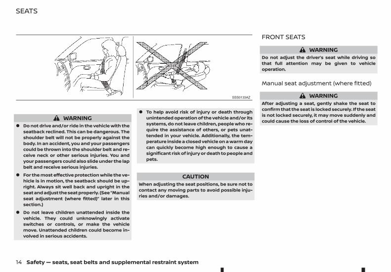
WARNING• Do not drive and/or ride in the vehicle with the
seatback reclined. This can be dangerous. Theshoulder belt will not be properly against thebody. In an accident, you and your passengerscould be thrown into the shoulder belt and re-ceive neck or other serious injuries. You andyour passengers could also slide under the lapbelt and receive serious injuries.
• For the most effective protection while the ve-hicle is in motion, the seatback should be up-right. Always sit well back and upright in theseat and adjust the seat properly. (See “Manualseat adjustment (where fitted)” later in thissection.)
• Do not leave children unattended inside thevehicle. They could unknowingly activateswitches or controls, or make the vehiclemove. Unattended children could become in-volved in serious accidents.
• To help avoid risk of injury or death throughunintended operation of the vehicle and/or itssystems, do not leave children, people who re-quire the assistance of others, or pets unat-tended in your vehicle. Additionally, the tem-perature inside a closed vehicle on a warm daycan quickly become high enough to cause asignificant risk of injury or death to people andpets.
CAUTIONWhen adjusting the seat positions, be sure not tocontact any moving parts to avoid possible inju-ries and/or damages.
FRONT SEATS
WARNINGDo not adjust the driver’s seat while driving sothat full attention may be given to vehicleoperation.
Manual seat adjustment (where fitted)
WARNINGAfter adjusting a seat, gently shake the seat toconfirm that the seat is locked securely. If the seatis not locked securely, it may move suddenly andcould cause the loss of control of the vehicle.
SSS0133AZ
SEATS
14 Safety — seats, seat belts and supplemental restraint system
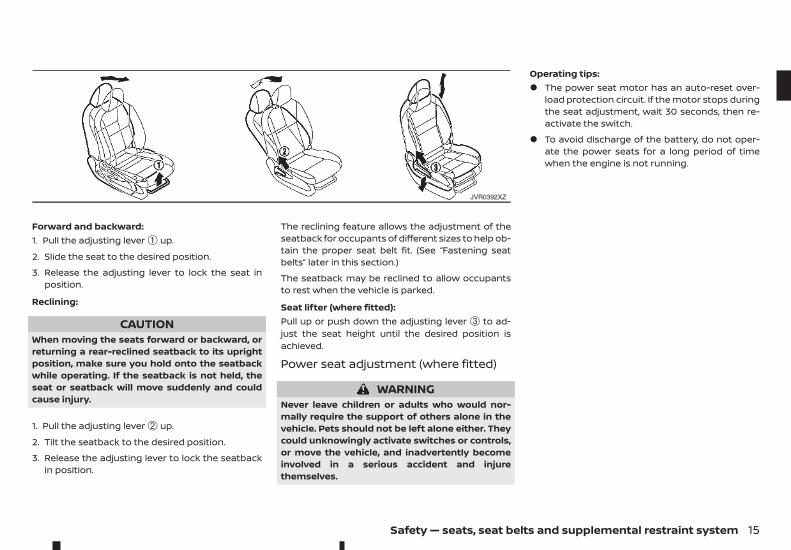
Forward and backward:1. Pull the adjusting lever ➀ up.
2. Slide the seat to the desired position.
3. Release the adjusting lever to lock the seat inposition.
Reclining:
CAUTIONWhen moving the seats forward or backward, orreturning a rear-reclined seatback to its uprightposition, make sure you hold onto the seatbackwhile operating. If the seatback is not held, theseat or seatback will move suddenly and couldcause injury.
1. Pull the adjusting lever ➁ up.
2. Tilt the seatback to the desired position.
3. Release the adjusting lever to lock the seatbackin position.
The reclining feature allows the adjustment of theseatback for occupants of different sizes to help ob-tain the proper seat belt fit. (See “Fastening seatbelts” later in this section.)
The seatback may be reclined to allow occupantsto rest when the vehicle is parked.
Seat lifter (where fitted):Pull up or push down the adjusting lever ➂ to ad-just the seat height until the desired position isachieved.
Power seat adjustment (where fitted)
WARNINGNever leave children or adults who would nor-mally require the support of others alone in thevehicle. Pets should not be left alone either. Theycould unknowingly activate switches or controls,or move the vehicle, and inadvertently becomeinvolved in a serious accident and injurethemselves.
Operating tips:• The power seat motor has an auto-reset over-
load protection circuit. If the motor stops duringthe seat adjustment, wait 30 seconds, then re-activate the switch.
• To avoid discharge of the battery, do not oper-ate the power seats for a long period of timewhen the engine is not running.
JVR0392XZ
Safety — seats, seat belts and supplemental restraint system 15
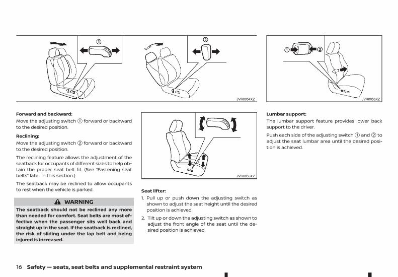
Forward and backward:Move the adjusting switch ➀ forward or backwardto the desired position.
Reclining:Move the adjusting switch ➁ forward or backwardto the desired position.
The reclining feature allows the adjustment of theseatback for occupants of different sizes to help ob-tain the proper seat belt fit. (See “Fastening seatbelts” later in this section.)
The seatback may be reclined to allow occupantsto rest when the vehicle is parked.
WARNINGThe seatback should not be reclined any morethan needed for comfort. Seat belts are most ef-fective when the passenger sits well back andstraight up in the seat. If the seatback is reclined,the risk of sliding under the lap belt and beinginjured is increased.
Seat lifter:1. Pull up or push down the adjusting switch as
shown to adjust the seat height until the desiredposition is achieved.
2. Tilt up or down the adjusting switch as shown toadjust the front angle of the seat until the de-sired position is achieved.
Lumbar support:The lumbar support feature provides lower backsupport to the driver.
Push each side of the adjusting switch ➀ and ➁ toadjust the seat lumbar area until the desired posi-tion is achieved.
JVR0054XZ
JVR0055XZ
JVR0056XZ
16 Safety — seats, seat belts and supplemental restraint system
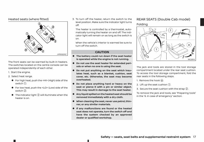
Heated seats (where fitted)
The front seats can be warmed by built-in heaters.The switches located on the centre console can beoperated independently of each other.
1. Start the engine.
2. Select heat range.
• For high heat, push the <HI> (High) side of theswitch ➀.
• For low heat, push the <LO> (Low) side of theswitch ➁.
• The indicator light ➂ will illuminate when theheater is on.
3. To turn off the heater, return the switch to thelevel position. Make sure the indicator light turnsoff.
The heater is controlled by a thermostat, auto-matically turning the heater on and off. The indi-cator light will remain on as long as the switch ison.
When the vehicle's interior is warmed be sure toturn off the switch.
CAUTION• The battery could run down if the seat heater
is operated while the engine is not running.
• Do not use the seat heater for extended peri-ods or when no one is using the seat.
• Do not put anything on the seat which insu-lates heat, such as a blanket, cushion, seatcover, etc. Otherwise, the seat may becomeoverheated.
• Do not place anything hard or heavy on theseat or pierce it with a pin or similar object.This may result in damage to the seat heater.
• Any liquid spilled on the heated seat should beremoved immediately with a dry cloth.
• When cleaning the seat, never use petrol, thin-ner, or any similar materials.
• If any malfunctions are found or the heatedseat does not operate, turn the switch off andhave the system checked by an approveddealer or qualified workshop.
REAR SEATS (Double Cab model)Folding
The jack and tools are stored in the tool storagecompartment located under the rear seat cushion.To access the tool storage compartment, fold therear seats in the following steps.
1. Remove the hookja .
2. Lift up the seat cushion ➀.
3. Secure the seat cushion with the strap ➁.
To remove the jack and tools, see “Preparing tools”in the “6. In case of emergency” section.
JVR0322XZ
NIC2816
Safety — seats, seat belts and supplemental restraint system 17
Do not drive the vehicle with the rear seat folded.
When returning the rear seat to the original posi-tion, be certain the seat belts and the buckles arepositioned properly. Secure the seat cushion usingthe hookja .
WARNING• Never allow anyone to ride on the rear seats
when they are in the fold-up position. Use ofthis area by passengers without properrestraints could result in serious injury ordeath in an accident or sudden stop.
• When folding or returning the rear seat, becareful not to squeeze your finger betweenthe seat cushion and the body side.
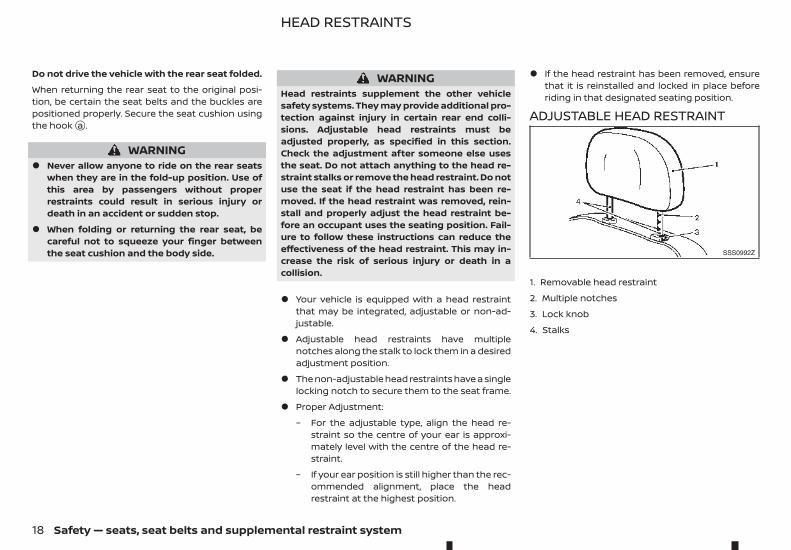
WARNINGHead restraints supplement the other vehiclesafety systems. They may provide additional pro-tection against injury in certain rear end colli-sions. Adjustable head restraints must beadjusted properly, as specified in this section.Check the adjustment after someone else usesthe seat. Do not attach anything to the head re-straint stalks or remove the head restraint. Do notuse the seat if the head restraint has been re-moved. If the head restraint was removed, rein-stall and properly adjust the head restraint be-fore an occupant uses the seating position. Fail-ure to follow these instructions can reduce theeffectiveness of the head restraint. This may in-crease the risk of serious injury or death in acollision.
• Your vehicle is equipped with a head restraintthat may be integrated, adjustable or non-ad-justable.
• Adjustable head restraints have multiplenotches along the stalk to lock them in a desiredadjustment position.
• The non-adjustable head restraints have a singlelocking notch to secure them to the seat frame.
• Proper Adjustment:
– For the adjustable type, align the head re-straint so the centre of your ear is approxi-mately level with the centre of the head re-straint.
– If your ear position is still higher than the rec-ommended alignment, place the headrestraint at the highest position.
• If the head restraint has been removed, ensurethat it is reinstalled and locked in place beforeriding in that designated seating position.
ADJUSTABLE HEAD RESTRAINT
1. Removable head restraint
2. Multiple notches
3. Lock knob
4. Stalks
SSS0992Z
HEAD RESTRAINTS
18 Safety — seats, seat belts and supplemental restraint system
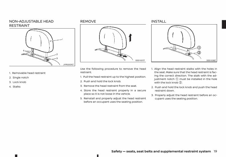
NON-ADJUSTABLE HEADRESTRAINT
1. Removable head restraint
2. Single notch
3. Lock knob
4. Stalks
REMOVE
Use the following procedure to remove the headrestraint.
1. Pull the head restraint up to the highest position.
2. Push and hold the lock knob.
3. Remove the head restraint from the seat.
4. Store the head restraint properly in a secureplace so it is not loose in the vehicle.
5. Reinstall and properly adjust the head restraintbefore an occupant uses the seating position.
INSTALL
1. Align the head restraint stalks with the holes inthe seat. Make sure that the head restraint is fac-ing the correct direction. The stalk with the ad-justment notch ➀ must be installed in the holewith the lock knob ➁.
2. Push and hold the lock knob and push the headrestraint down.
3. Properly adjust the head restraint before an oc-cupant uses the seating position.
JVR0203XZ
SSS1037Z SSS1038Z
Safety — seats, seat belts and supplemental restraint system 19
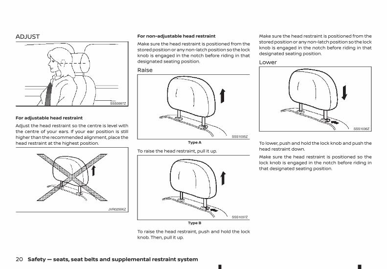
ADJUST
For adjustable head restraint
Adjust the head restraint so the centre is level withthe centre of your ears. If your ear position is stillhigher than the recommended alignment, place thehead restraint at the highest position.
For non-adjustable head restraint
Make sure the head restraint is positioned from thestored position or any non-latch position so the lockknob is engaged in the notch before riding in thatdesignated seating position.
Raise
To raise the head restraint, pull it up.
To raise the head restraint, push and hold the lockknob. Then, pull it up.
Make sure the head restraint is positioned from thestored position or any non-latch position so the lockknob is engaged in the notch before riding in thatdesignated seating position.
Lower
To lower, push and hold the lock knob and push thehead restraint down.
Make sure the head restraint is positioned so thelock knob is engaged in the notch before riding inthat designated seating position.
SSS0997Z
JVR0259XZ
SSS1035Z
Type A
SSS1037Z
Type B
SSS1036Z
20 Safety — seats, seat belts and supplemental restraint system
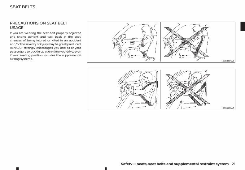
PRECAUTIONS ON SEAT BELTUSAGEIf you are wearing the seat belt properly adjustedand sitting upright and well back in the seat,chances of being injured or killed in an accidentand/or the severity of injury may be greatly reduced.RENAULT strongly encourages you and all of yourpassengers to buckle up every time you drive, evenif your seating position includes the supplementalair bag systems.
SSS0134AZ
SSS0136AZ
SEAT BELTS
Safety — seats, seat belts and supplemental restraint system 21
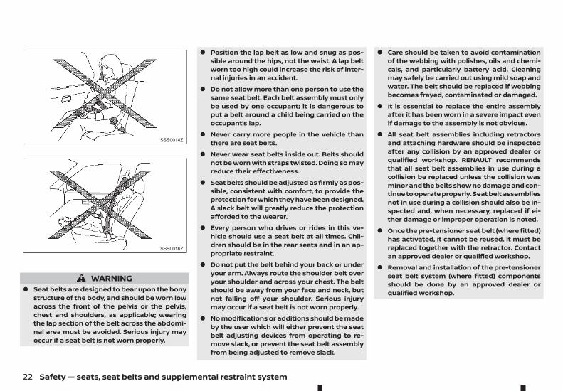
WARNING• Seat belts are designed to bear upon the bony
structure of the body, and should be worn lowacross the front of the pelvis or the pelvis,chest and shoulders, as applicable; wearingthe lap section of the belt across the abdomi-nal area must be avoided. Serious injury mayoccur if a seat belt is not worn properly.
• Position the lap belt as low and snug as pos-sible around the hips, not the waist. A lap beltworn too high could increase the risk of inter-nal injuries in an accident.
• Do not allow more than one person to use thesame seat belt. Each belt assembly must onlybe used by one occupant; it is dangerous toput a belt around a child being carried on theoccupant’s lap.
• Never carry more people in the vehicle thanthere are seat belts.
• Never wear seat belts inside out. Belts shouldnot be worn with straps twisted. Doing so mayreduce their effectiveness.
• Seat belts should be adjusted as firmly as pos-sible, consistent with comfort, to provide theprotection for which they have been designed.A slack belt will greatly reduce the protectionafforded to the wearer.
• Every person who drives or rides in this ve-hicle should use a seat belt at all times. Chil-dren should be in the rear seats and in an ap-propriate restraint.
• Do not put the belt behind your back or underyour arm. Always route the shoulder belt overyour shoulder and across your chest. The beltshould be away from your face and neck, butnot falling off your shoulder. Serious injurymay occur if a seat belt is not worn properly.
• No modifications or additions should be madeby the user which will either prevent the seatbelt adjusting devices from operating to re-move slack, or prevent the seat belt assemblyfrom being adjusted to remove slack.
• Care should be taken to avoid contaminationof the webbing with polishes, oils and chemi-cals, and particularly battery acid. Cleaningmay safely be carried out using mild soap andwater. The belt should be replaced if webbingbecomes frayed, contaminated or damaged.
• It is essential to replace the entire assemblyafter it has been worn in a severe impact evenif damage to the assembly is not obvious.
• All seat belt assemblies including retractorsand attaching hardware should be inspectedafter any collision by an approved dealer orqualified workshop. RENAULT recommendsthat all seat belt assemblies in use during acollision be replaced unless the collision wasminor and the belts show no damage and con-tinue to operate properly. Seat belt assembliesnot in use during a collision should also be in-spected and, when necessary, replaced if ei-ther damage or improper operation is noted.
• Once the pre-tensioner seat belt (where fitted)has activated, it cannot be reused. It must bereplaced together with the retractor. Contactan approved dealer or qualified workshop.
• Removal and installation of the pre-tensionerseat belt system (where fitted) componentsshould be done by an approved dealer orqualified workshop.
SSS0014Z
SSS0016Z
22 Safety — seats, seat belts and supplemental restraint system
CHILD SAFETY
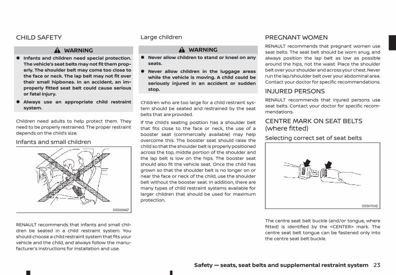
WARNING• Infants and children need special protection.
The vehicle’s seat belts may not fit them prop-erly. The shoulder belt may come too close tothe face or neck. The lap belt may not fit overtheir small hipbones. In an accident, an im-properly fitted seat belt could cause seriousor fatal injury.
• Always use an appropriate child restraintsystem.
Children need adults to help protect them. Theyneed to be properly restrained. The proper restraintdepends on the child’s size.
Infants and small children
RENAULT recommends that infants and small chil-dren be seated in a child restraint system. Youshould choose a child restraint system that fits yourvehicle and the child, and always follow the manu-facturer’s instructions for installation and use.
Large children
WARNING• Never allow children to stand or kneel on any
seats.
• Never allow children in the luggage areaswhile the vehicle is moving. A child could beseriously injured in an accident or suddenstop.
Children who are too large for a child restraint sys-tem should be seated and restrained by the seatbelts that are provided.
If the child’s seating position has a shoulder beltthat fits close to the face or neck, the use of abooster seat (commercially available) may helpovercome this. The booster seat should raise thechild so that the shoulder belt is properly positionedacross the top, middle portion of the shoulder andthe lap belt is low on the hips. The booster seatshould also fit the vehicle seat. Once the child hasgrown so that the shoulder belt is no longer on ornear the face or neck of the child, use the shoulderbelt without the booster seat. In addition, there aremany types of child restraint systems available forlarger children that should be used for maximumprotection.
PREGNANT WOMENRENAULT recommends that pregnant women useseat belts. The seat belt should be worn snug, andalways position the lap belt as low as possiblearound the hips, not the waist. Place the shoulderbelt over your shoulder and across your chest. Neverrun the lap/shoulder belt over your abdominal area.Contact your doctor for specific recommendations.
INJURED PERSONSRENAULT recommends that injured persons useseat belts. Contact your doctor for specific recom-mendations.
CENTRE MARK ON SEAT BELTS(where fitted)Selecting correct set of seat belts
The centre seat belt buckle (and/or tongue, wherefitted) is identified by the <CENTER> mark. Thecentre seat belt tongue can be fastened only intothe centre seat belt buckle.
SSS0099ZSSS0703Z
Safety — seats, seat belts and supplemental restraint system 23
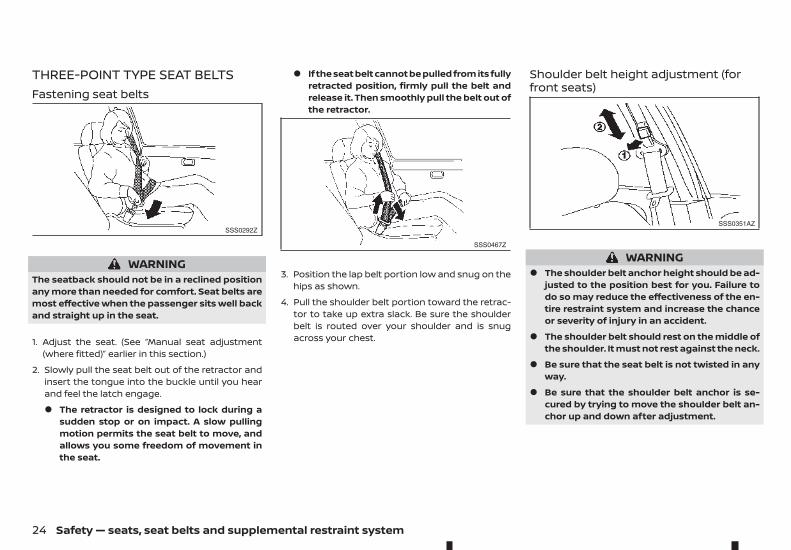
THREE-POINT TYPE SEAT BELTSFastening seat belts
WARNINGThe seatback should not be in a reclined positionany more than needed for comfort. Seat belts aremost effective when the passenger sits well backand straight up in the seat.
1. Adjust the seat. (See “Manual seat adjustment(where fitted)” earlier in this section.)
2. Slowly pull the seat belt out of the retractor andinsert the tongue into the buckle until you hearand feel the latch engage.
• The retractor is designed to lock during asudden stop or on impact. A slow pullingmotion permits the seat belt to move, andallows you some freedom of movement inthe seat.
• If the seat belt cannot be pulled from its fullyretracted position, firmly pull the belt andrelease it. Then smoothly pull the belt out ofthe retractor.
3. Position the lap belt portion low and snug on thehips as shown.
4. Pull the shoulder belt portion toward the retrac-tor to take up extra slack. Be sure the shoulderbelt is routed over your shoulder and is snugacross your chest.
Shoulder belt height adjustment (forfront seats)
WARNING• The shoulder belt anchor height should be ad-
justed to the position best for you. Failure todo so may reduce the effectiveness of the en-tire restraint system and increase the chanceor severity of injury in an accident.
• The shoulder belt should rest on the middle ofthe shoulder. It must not rest against the neck.
• Be sure that the seat belt is not twisted in anyway.
• Be sure that the shoulder belt anchor is se-cured by trying to move the shoulder belt an-chor up and down after adjustment.
SSS0292Z
SSS0467Z
SSS0351AZ
24 Safety — seats, seat belts and supplemental restraint system
To adjust, pull on the release button ➀ and movethe shoulder belt anchor to the proper position ➁,so that the belt passes over the centre of the shoul-der. The belt should be away from your face andneck, but not falling off your shoulder. Release thebutton to lock the shoulder belt anchor into posi-tion.
Unfastening seat beltsPush the button on the buckle. The seat belt auto-matically retracts.
Checking seat belt operationSeat belt retractors are designed to lock seat beltmovement:
• When the seat belt is pulled quickly from the re-tractor.
• When the vehicle slows down rapidly.
To increase your confidence in the seat belts, checkthe operation by grasping the shoulder belt andpulling forward quickly. The retractor should lockand restrict further belt movement. If the retractordoes not lock during this check, contact an ap-proved dealer or qualified workshop immediately.
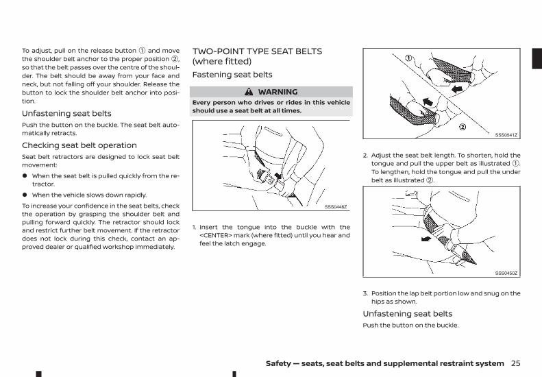
TWO-POINT TYPE SEAT BELTS(where fitted)Fastening seat belts
WARNINGEvery person who drives or rides in this vehicleshould use a seat belt at all times.
1. Insert the tongue into the buckle with the<CENTER> mark (where fitted) until you hear andfeel the latch engage.
2. Adjust the seat belt length. To shorten, hold thetongue and pull the upper belt as illustrated ➀.To lengthen, hold the tongue and pull the underbelt as illustrated ➁.
3. Position the lap belt portion low and snug on thehips as shown.
Unfastening seat beltsPush the button on the buckle.
SSS0448Z
SSS0541Z
SSS0450Z
Safety — seats, seat belts and supplemental restraint system 25
SEAT BELT MAINTENANCEPeriodically check that the seat belt and all themetal components, such as buckles, tongues, re-tractors, flexible wires and anchors, work properly. Ifloose parts, deterioration, cuts or other damage onthe seat belt webbing is found, the entire seat beltassembly should be replaced.
If dirt builds up in the shoulder belt guide of the seatbelt anchors, the seat belts may retract slowly. Wipethe shoulder belt guide with a clean, dry cloth.
To clean the seat belt webbing, apply a mild soapsolution or any solution recommended for cleaningupholstery or carpet. Then wipe with a cloth andallow the seat belts to dry in the shade. Do not allowthe seat belts to retract until they are completelydry.
PRECAUTIONS ON CHILDRESTRAINT USAGE
WARNING• Infants and small children should never be
carried on your lap. It is not possible for eventhe strongest adult to resist the forces of a se-vere accident. The child could be crushed be-tween the adult and parts of the vehicle. Also,it is dangerous to put a seat belt around a childbeing carried on the occupant’s lap.
• Infants and children need special protection.The vehicle’s seat belts may not fit them prop-erly. The shoulder belt may come too close tothe face or neck. The lap belt may not fit overtheir small hip bones. In an accident, an im-properly fitting seat belt could cause seriousor fatal injury.
• Infants and small children should always beplaced in an appropriate child restraint sys-tem while riding in the vehicle. Failure to use achild restraint system can result in serious in-jury or death.
• Child restraint systems specially designed forinfants and small children are available fromseveral manufacturers. When selecting anychild restraint systems, place your child in thechild restraint system and check the variousadjustments to be sure that the child restraintsystem is compatible with your child. Alwaysfollow the manufacturer’s instructions for in-stallation and use.
• RENAULT recommends that the child restraintsystem be installed in the rear seat. Accordingto accident statistics, children are safer whenproperly restrained in the rear seat rather thanin the front seat.
• Follow all of the child restraint system manu-facturer’s instructions for installation and use.When purchasing a child restraint system, besure to select one which will fit your child andvehicle. It may not be possible to properly in-stall some types of child restraint systems inyour vehicle.
• The direction of the child restraint, eitherfront-facing or rear-facing, depends on thetype of the child restraint and the size of thechild. Refer to the child restraint manufactur-er's instructions for details.
SSS0099Z
CHILD RESTRAINTS
26 Safety — seats, seat belts and supplemental restraint system
• For a front-facing child restraint system, checkto make sure the shoulder belt does not fitclose to child’s face or neck. If you must installa front-facing child restraint system in thefront seat, see “Installation on front passen-ger’s seat” later in this section.
• Never install a rear-facing child restraint sys-tem on the front passenger's seat when thefront passenger's air bag is active. Supple-mental front-impact air bags inflate withgreat force. A rear-facing child restraint sys-tem could be struck by the supplementalfront-impact air bags in an accident and couldseriously injure or kill your child.
• Adjustable seatbacks should be positioned tofit a child restraint system, but as upright aspossible. see “Installation on rear outboardseats” later in this section and “Child restraintinstallation using three-point type seat belt”later in this section.
• If the seat belt in the position where a childrestraint system is installed requires a lockingclip and if it is not used, injuries could resultfrom a child restraint system tipping over dur-ing normal vehicle braking or cornering.
• After attaching a child restraint system, test itbefore you place the child in it. Tilt it from sideto side. Try to tug it forward and check if it isheld securely in place. The child restraint sys-tem should not move more than 25 mm (1 in).If the restraint is not secure, tighten the belt asnecessary, or install the restraint in anotherseat and test it again.
• Check the child restraint system in your ve-hicle to be sure that it is compatible with thevehicle’s seat belt system.
• If a child restraint system is not anchoredproperly, the risk of a child being injured in acollision or a sudden stop greatly increases.
• Improper use of a child restraint system canincrease the risk or severity of injury for boththe child and other occupants in the vehicle.
• Always use an appropriate child restraint sys-tem. An improperly installed child restraintsystem could lead to serious injury or death inan accident.
• When the child restraint system is not in use,keep it secured with the ISOFIX and i-Size childrestraint system or a seat belt to prevent itfrom being thrown around in case of a suddenstop or accident.
RENAULT recommends that infants and small chil-dren be seated in a child restraint system. Youshould choose a child restraint system that fits yourvehicle and always follow the manufacturer’s in-structions for installation and use. In addition, thereare many types of child restraint systems availablefor larger children that should be used for maximumprotection.
CAUTIONRemember that a child restraint system left in aclosed vehicle can become very hot. Check theseating surface and buckles before placing yourchild in a child restraint system.
UNIVERSAL CHILD RESTRAINTS FORFRONT SEAT AND REAR SEATS (forEurope)NOTE
Child restraints approved to UN Regulation No. 44or No. 129 are clearly marked with the categoriessuch as Universal, Semi-universal or ISOFIX.
When selecting any child restraint, keep the follow-ing points in mind:
• Choose a child restraint that complies with thelatest European safety standard, UN RegulationNo. 44 or No. 129.
• Place your child in the child restraint and checkthe various adjustments to be sure the child re-straint is compatible with your child. Always fol-low all of the recommended procedures.
• Check the child restraint in your vehicle to besure it is compatible with vehicle's retention sys-tem.
• Refer to the tables later in this section for a list ofthe recommended fitment positions of child re-straints for your vehicle.
Safety — seats, seat belts and supplemental restraint system 27

Mass group of child restraintMass group Child's weight
Group 0 up to 10 kgGroup 0+ up to 13 kgGroup I 9 to 18 kgGroup II 15 to 25 kgGroup III 22 to 36 kg
Examples of child seat types:
JVR0371XZ
Child safety seat categories 0 and 0+
JVR0372XZ
Child safety seat categories 0+ and I
JVR0373XZ
Child safety seat categories II and III
28 Safety — seats, seat belts and supplemental restraint system
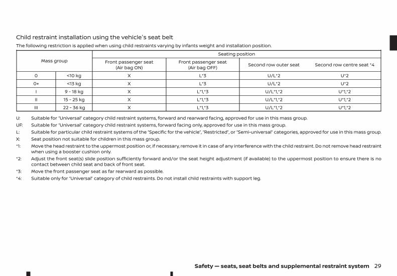
Child restraint installation using the vehicle's seat beltThe following restriction is applied when using child restraints varying by infants weight and installation position.
Mass groupSeating position
Front passenger seat(Air bag ON)
Front passenger seat(Air bag OFF) Second row outer seat Second row centre seat *4
0 <10 kg X L*3 U/L*2 U*2
0+ <13 kg X L*3 U/L*2 U*2
I 9 - 18 kg X L*1,*3 U/L*1,*2 U*1,*2
II 15 - 25 kg X L*1,*3 U/L*1,*2 U*1,*2
III 22 - 36 kg X L*1,*3 U/L*1,*2 U*1,*2
U: Suitable for “Universal” category child restraint systems, forward and rearward facing, approved for use in this mass group.UF: Suitable for “Universal” category child restraint systems, forward facing only, approved for use in this mass group.L: Suitable for particular child restraint systems of the “Specific for the vehicle”, “Restricted”, or “Semi-universal” categories, approved for use in this mass group.X: Seat position not suitable for children in this mass group.*1: Move the head restraint to the uppermost position or, if necessary, remove it in case of any interference with the child restraint. Do not remove head restraint
when using a booster cushion only.*2: Adjust the front seat(s) slide position sufficiently forward and/or the seat height adjustment (if available) to the uppermost position to ensure there is no
contact between child seat and back of front seat.*3: Move the front passenger seat as far rearward as possible.*4: Suitable only for “Universal” category of child restraints. Do not install child restraints with support leg.
Safety — seats, seat belts and supplemental restraint system 29
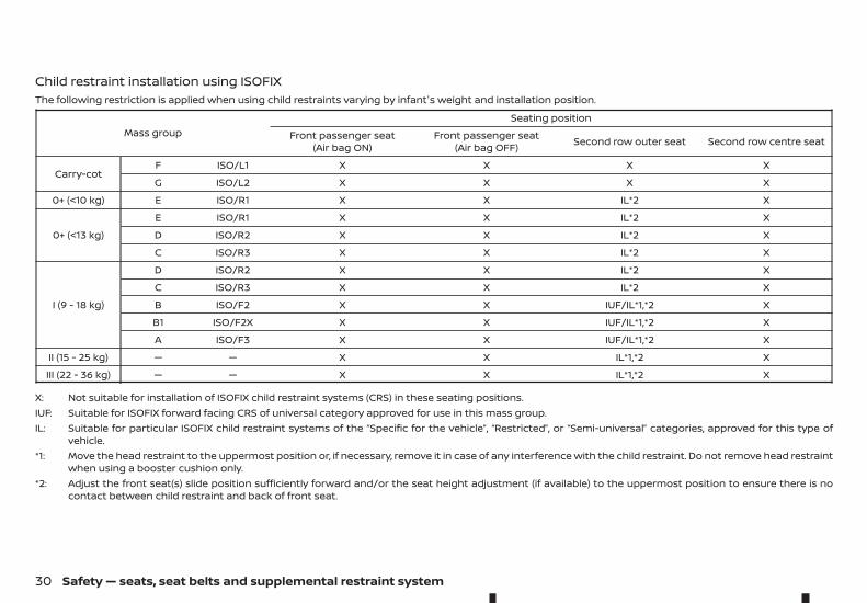
Child restraint installation using ISOFIXThe following restriction is applied when using child restraints varying by infant's weight and installation position.
Mass groupSeating position
Front passenger seat(Air bag ON)
Front passenger seat(Air bag OFF) Second row outer seat Second row centre seat
Carry-cotF ISO/L1 X X X X
G ISO/L2 X X X X
0+ (<10 kg) E ISO/R1 X X IL*2 X
0+ (<13 kg)
E ISO/R1 X X IL*2 X
D ISO/R2 X X IL*2 X
C ISO/R3 X X IL*2 X
I (9 - 18 kg)
D ISO/R2 X X IL*2 X
C ISO/R3 X X IL*2 X
B ISO/F2 X X IUF/IL*1,*2 X
B1 ISO/F2X X X IUF/IL*1,*2 X
A ISO/F3 X X IUF/IL*1,*2 X
II (15 - 25 kg) — — X X IL*1,*2 X
III (22 - 36 kg) — — X X IL*1,*2 X
X: Not suitable for installation of ISOFIX child restraint systems (CRS) in these seating positions.IUF: Suitable for ISOFIX forward facing CRS of universal category approved for use in this mass group.IL: Suitable for particular ISOFIX child restraint systems of the “Specific for the vehicle”, “Restricted”, or “Semi-universal” categories, approved for this type of
vehicle.*1: Move the head restraint to the uppermost position or, if necessary, remove it in case of any interference with the child restraint. Do not remove head restraint
when using a booster cushion only.*2: Adjust the front seat(s) slide position sufficiently forward and/or the seat height adjustment (if available) to the uppermost position to ensure there is no
contact between child restraint and back of front seat.
30 Safety — seats, seat belts and supplemental restraint system
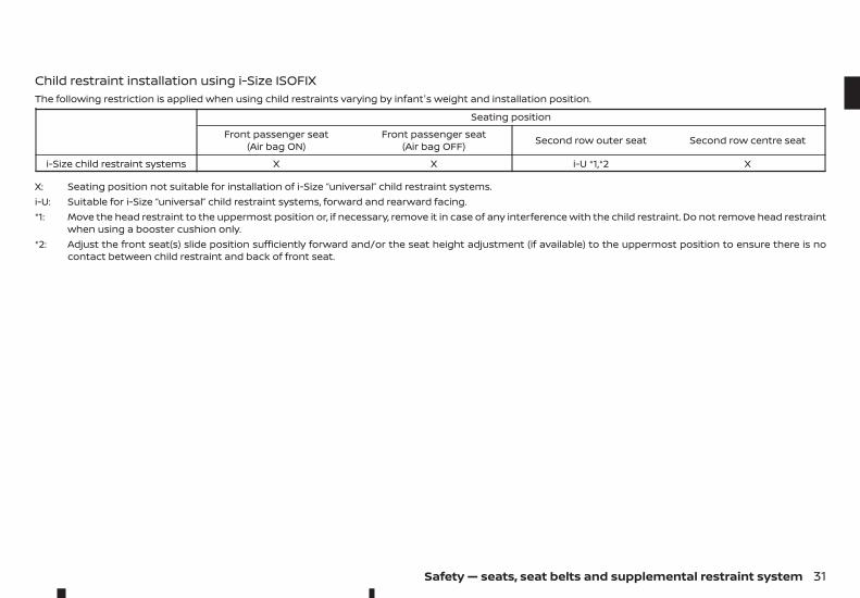
Child restraint installation using i-Size ISOFIXThe following restriction is applied when using child restraints varying by infant's weight and installation position.
Seating position
Front passenger seat(Air bag ON)
Front passenger seat(Air bag OFF) Second row outer seat Second row centre seat
i-Size child restraint systems X X i-U *1,*2 X
X: Seating position not suitable for installation of i-Size “universal” child restraint systems.i-U: Suitable for i-Size “universal” child restraint systems, forward and rearward facing.*1: Move the head restraint to the uppermost position or, if necessary, remove it in case of any interference with the child restraint. Do not remove head restraint
when using a booster cushion only.*2: Adjust the front seat(s) slide position sufficiently forward and/or the seat height adjustment (if available) to the uppermost position to ensure there is no
contact between child restraint and back of front seat.
Safety — seats, seat belts and supplemental restraint system 31
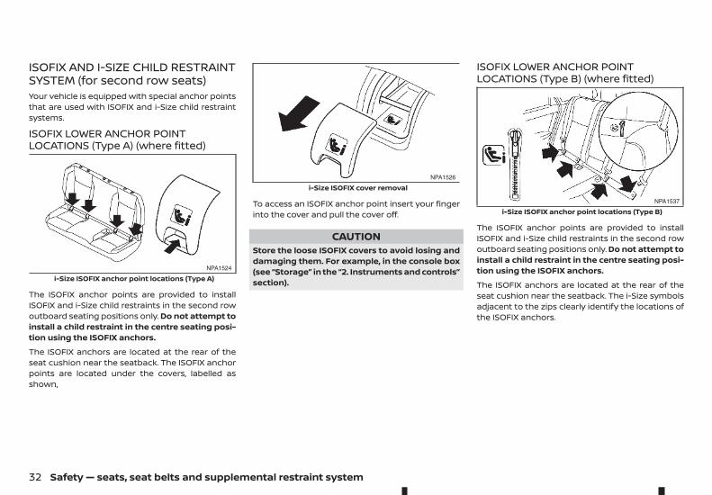
ISOFIX AND I-SIZE CHILD RESTRAINTSYSTEM (for second row seats)Your vehicle is equipped with special anchor pointsthat are used with ISOFIX and i-Size child restraintsystems.
ISOFIX LOWER ANCHOR POINTLOCATIONS (Type A) (where fitted)
The ISOFIX anchor points are provided to installISOFIX and i-Size child restraints in the second rowoutboard seating positions only. Do not attempt toinstall a child restraint in the centre seating posi-tion using the ISOFIX anchors.
The ISOFIX anchors are located at the rear of theseat cushion near the seatback. The ISOFIX anchorpoints are located under the covers, labelled asshown,
To access an ISOFIX anchor point insert your fingerinto the cover and pull the cover off.
CAUTIONStore the loose ISOFIX covers to avoid losing anddamaging them. For example, in the console box(see “Storage” in the “2. Instruments and controls”section).
ISOFIX LOWER ANCHOR POINTLOCATIONS (Type B) (where fitted)
The ISOFIX anchor points are provided to installISOFIX and i-Size child restraints in the second rowoutboard seating positions only. Do not attempt toinstall a child restraint in the centre seating posi-tion using the ISOFIX anchors.
The ISOFIX anchors are located at the rear of theseat cushion near the seatback. The i-Size symbolsadjacent to the zips clearly identify the locations ofthe ISOFIX anchors.
NPA1524
i-Size ISOFIX anchor point locations (Type A)
NPA1526
i-Size ISOFIX cover removal
NPA1537
i-Size ISOFIX anchor point locations (Type B)
32 Safety — seats, seat belts and supplemental restraint system
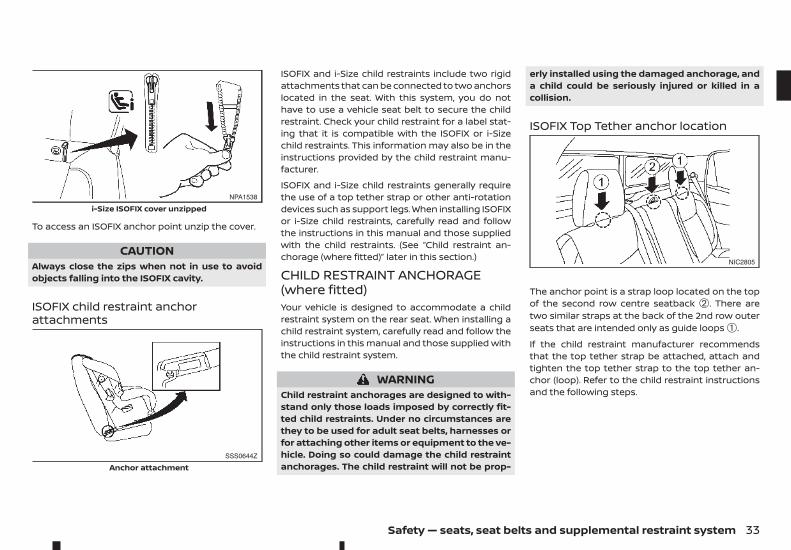
To access an ISOFIX anchor point unzip the cover.
CAUTIONAlways close the zips when not in use to avoidobjects falling into the ISOFIX cavity.
ISOFIX child restraint anchorattachments
ISOFIX and i-Size child restraints include two rigidattachments that can be connected to two anchorslocated in the seat. With this system, you do nothave to use a vehicle seat belt to secure the childrestraint. Check your child restraint for a label stat-ing that it is compatible with the ISOFIX or i-Sizechild restraints. This information may also be in theinstructions provided by the child restraint manu-facturer.
ISOFIX and i-Size child restraints generally requirethe use of a top tether strap or other anti-rotationdevices such as support legs. When installing ISOFIXor i-Size child restraints, carefully read and followthe instructions in this manual and those suppliedwith the child restraints. (See “Child restraint an-chorage (where fitted)” later in this section.)
CHILD RESTRAINT ANCHORAGE(where fitted)Your vehicle is designed to accommodate a childrestraint system on the rear seat. When installing achild restraint system, carefully read and follow theinstructions in this manual and those supplied withthe child restraint system.
WARNINGChild restraint anchorages are designed to with-stand only those loads imposed by correctly fit-ted child restraints. Under no circumstances arethey to be used for adult seat belts, harnesses orfor attaching other items or equipment to the ve-hicle. Doing so could damage the child restraintanchorages. The child restraint will not be prop-
erly installed using the damaged anchorage, anda child could be seriously injured or killed in acollision.
ISOFIX Top Tether anchor location
The anchor point is a strap loop located on the topof the second row centre seatback ➁. There aretwo similar straps at the back of the 2nd row outerseats that are intended only as guide loops ➀.
If the child restraint manufacturer recommendsthat the top tether strap be attached, attach andtighten the top tether strap to the top tether an-chor (loop). Refer to the child restraint instructionsand the following steps.
NPA1538
i-Size ISOFIX cover unzipped
SSS0644Z
Anchor attachment
NIC2805
Safety — seats, seat belts and supplemental restraint system 33
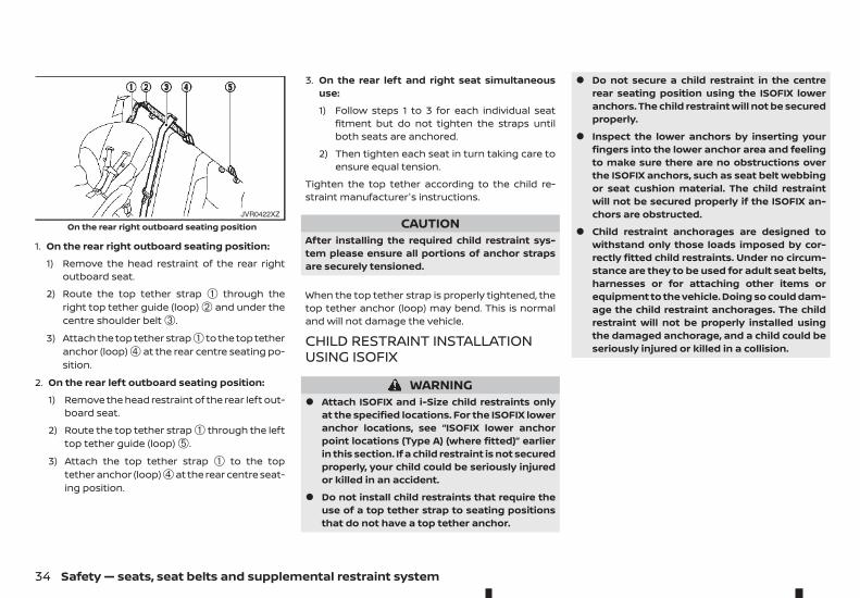
1. On the rear right outboard seating position:
1) Remove the head restraint of the rear rightoutboard seat.
2) Route the top tether strap ➀ through theright top tether guide (loop) ➁ and under thecentre shoulder belt ➂.
3) Attach the top tether strap➀ to the top tetheranchor (loop) ➃ at the rear centre seating po-sition.
2. On the rear left outboard seating position:
1) Remove the head restraint of the rear left out-board seat.
2) Route the top tether strap ➀ through the lefttop tether guide (loop) ➄.
3) Attach the top tether strap ➀ to the toptether anchor (loop)➃at the rear centre seat-ing position.
3. On the rear left and right seat simultaneoususe:
1) Follow steps 1 to 3 for each individual seatfitment but do not tighten the straps untilboth seats are anchored.
2) Then tighten each seat in turn taking care toensure equal tension.
Tighten the top tether according to the child re-straint manufacturer's instructions.
CAUTIONAfter installing the required child restraint sys-tem please ensure all portions of anchor strapsare securely tensioned.
When the top tether strap is properly tightened, thetop tether anchor (loop) may bend. This is normaland will not damage the vehicle.
CHILD RESTRAINT INSTALLATIONUSING ISOFIX
WARNING• Attach ISOFIX and i-Size child restraints only
at the specified locations. For the ISOFIX loweranchor locations, see “ISOFIX lower anchorpoint locations (Type A) (where fitted)” earlierin this section. If a child restraint is not securedproperly, your child could be seriously injuredor killed in an accident.
• Do not install child restraints that require theuse of a top tether strap to seating positionsthat do not have a top tether anchor.
• Do not secure a child restraint in the centrerear seating position using the ISOFIX loweranchors. The child restraint will not be securedproperly.
• Inspect the lower anchors by inserting yourfingers into the lower anchor area and feelingto make sure there are no obstructions overthe ISOFIX anchors, such as seat belt webbingor seat cushion material. The child restraintwill not be secured properly if the ISOFIX an-chors are obstructed.
• Child restraint anchorages are designed towithstand only those loads imposed by cor-rectly fitted child restraints. Under no circum-stance are they to be used for adult seat belts,harnesses or for attaching other items orequipment to the vehicle. Doing so could dam-age the child restraint anchorages. The childrestraint will not be properly installed usingthe damaged anchorage, and a child could beseriously injured or killed in a collision.
JVR0422XZ
On the rear right outboard seating position
34 Safety — seats, seat belts and supplemental restraint system
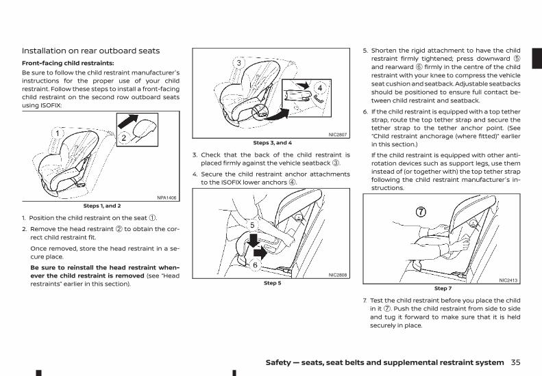
Installation on rear outboard seatsFront-facing child restraints:Be sure to follow the child restraint manufacturer'sinstructions for the proper use of your childrestraint. Follow these steps to install a front-facingchild restraint on the second row outboard seatsusing ISOFIX:
1. Position the child restraint on the seat ➀.
2. Remove the head restraint ➁ to obtain the cor-rect child restraint fit.
Once removed, store the head restraint in a se-cure place.
Be sure to reinstall the head restraint when-ever the child restraint is removed (see “Headrestraints” earlier in this section).
3. Check that the back of the child restraint isplaced firmly against the vehicle seatback ➂.
4. Secure the child restraint anchor attachmentsto the ISOFIX lower anchors ➃.
5. Shorten the rigid attachment to have the childrestraint firmly tightened; press downward ➄and rearward ➅ firmly in the centre of the childrestraint with your knee to compress the vehicleseat cushion and seatback. Adjustable seatbacksshould be positioned to ensure full contact be-tween child restraint and seatback.
6. If the child restraint is equipped with a top tetherstrap, route the top tether strap and secure thetether strap to the tether anchor point. (See“Child restraint anchorage (where fitted)” earlierin this section.)
If the child restraint is equipped with other anti-rotation devices such as support legs, use theminstead of (or together with) the top tether strapfollowing the child restraint manufacturer's in-structions.
7. Test the child restraint before you place the childin it ➆. Push the child restraint from side to sideand tug it forward to make sure that it is heldsecurely in place.
NPA1406
Steps 1, and 2
NIC2807
Steps 3, and 4
NIC2808
Step 5 NIC2413
Step 7
Safety — seats, seat belts and supplemental restraint system 35
8. Check to make sure that the child restraint isproperly secured prior to each use. If the childrestraint is loose, repeat steps 1 through 7.
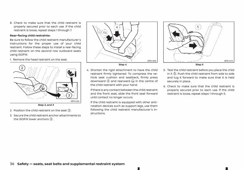
Rear-facing child restraints:Be sure to follow the child restraint manufacturer'sinstructions for the proper use of your childrestraint. Follow these steps to install a rear-facingchild restraint on the second row outboard seatsusing ISOFIX:
1. Remove the head restraint on the seat.
2. Position the child restraint on the seat ➁.
3. Secure the child restraint anchor attachments tothe ISOFIX lower anchors ➂.
4. Shorten the rigid attachment to have the childrestraint firmly tightened. To compress the ve-hicle seat cushion and seatback, firmly pressdownward ➃ and rearward j4a in the centre ofthe child restraint with your hand.
If there is any contact between the child restraintand the front seat, slide the front seat forwarduntil contact no longer occurs.
If the child restraint is equipped with other anti-rotation devices such as support legs, use themfollowing the child restraint manufacturer's in-structions.
5. Test the child restraint before you place the childin it ➄. Push the child restraint from side to sideand tug it forward to make sure that it is heldsecurely in place.
6. Check to make sure that the child restraint isproperly secured prior to each use. If the childrestraint is loose, repeat steps 1 through 5.
NPA1525
Step 2, and 3
NPA1409
Step 4NPA1410
Step 5
36 Safety — seats, seat belts and supplemental restraint system
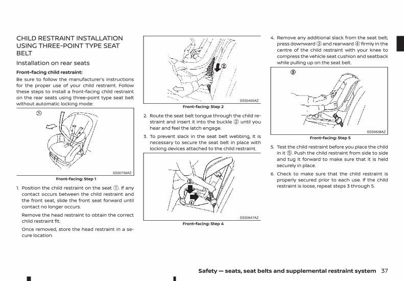
CHILD RESTRAINT INSTALLATIONUSING THREE-POINT TYPE SEATBELTInstallation on rear seatsFront-facing child restraint:Be sure to follow the manufacturer’s instructionsfor the proper use of your child restraint. Followthese steps to install a front-facing child restrainton the rear seats using three-point type seat beltwithout automatic locking mode:
1. Position the child restraint on the seat ➀. If anycontact occurs between the child restraint andthe front seat, slide the front seat forward untilcontact no longer occurs.
Remove the head restraint to obtain the correctchild restraint fit.
Once removed, store the head restraint in a se-cure location.
2. Route the seat belt tongue through the child re-straint and insert it into the buckle ➁ until youhear and feel the latch engage.
3. To prevent slack in the seat belt webbing, it isnecessary to secure the seat belt in place withlocking devices attached to the child restraint.
4. Remove any additional slack from the seat belt;press downward ➂ and rearward ➃ firmly in thecentre of the child restraint with your knee tocompress the vehicle seat cushion and seatbackwhile pulling up on the seat belt.
5. Test the child restraint before you place the childin it ➄. Push the child restraint from side to sideand tug it forward to make sure that it is heldsecurely in place.
6. Check to make sure that the child restraint isproperly secured prior to each use. If the childrestraint is loose, repeat steps 3 through 5.
SSS0758AZ
Front-facing: Step 1
SSS0493AZ
Front-facing: Step 2
SSS0647AZ
Front-facing: Step 4
SSS0638AZ
Front-facing: Step 5
Safety — seats, seat belts and supplemental restraint system 37
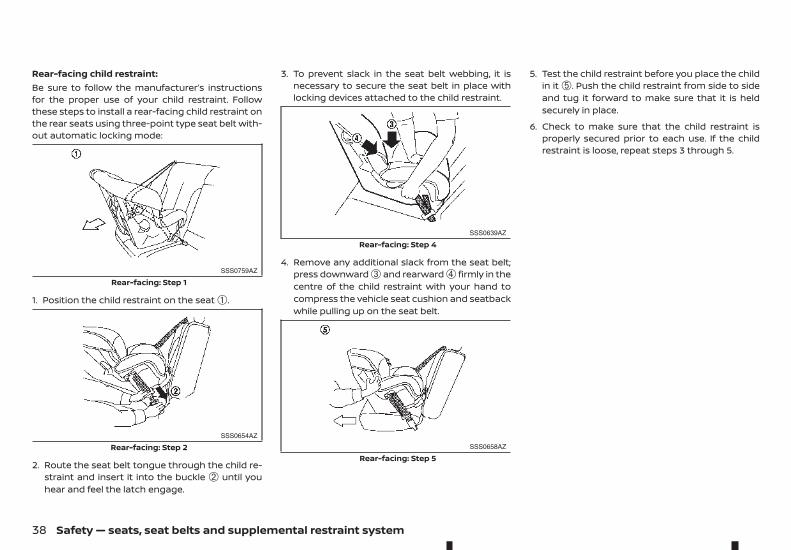
Rear-facing child restraint:Be sure to follow the manufacturer’s instructionsfor the proper use of your child restraint. Followthese steps to install a rear-facing child restraint onthe rear seats using three-point type seat belt with-out automatic locking mode:
1. Position the child restraint on the seat ➀.
2. Route the seat belt tongue through the child re-straint and insert it into the buckle ➁ until youhear and feel the latch engage.
3. To prevent slack in the seat belt webbing, it isnecessary to secure the seat belt in place withlocking devices attached to the child restraint.
4. Remove any additional slack from the seat belt;press downward ➂ and rearward ➃ firmly in thecentre of the child restraint with your hand tocompress the vehicle seat cushion and seatbackwhile pulling up on the seat belt.
5. Test the child restraint before you place the childin it ➄. Push the child restraint from side to sideand tug it forward to make sure that it is heldsecurely in place.
6. Check to make sure that the child restraint isproperly secured prior to each use. If the childrestraint is loose, repeat steps 3 through 5.
SSS0759AZ
Rear-facing: Step 1
SSS0654AZ
Rear-facing: Step 2
SSS0639AZ
Rear-facing: Step 4
SSS0658AZ
Rear-facing: Step 5
38 Safety — seats, seat belts and supplemental restraint system
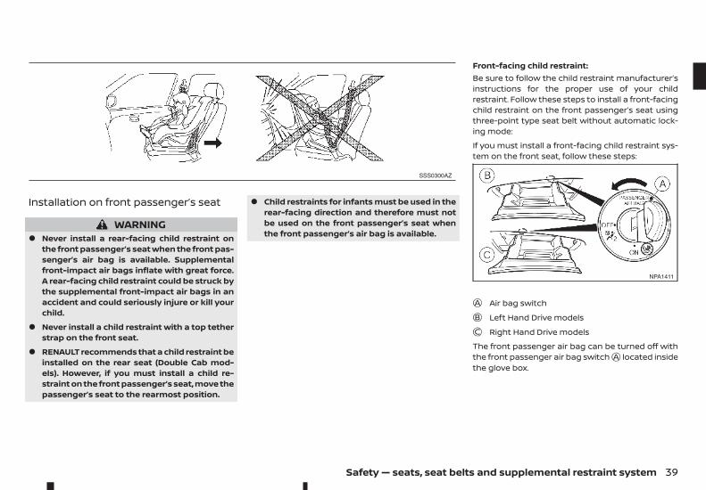
Installation on front passenger’s seat
WARNING• Never install a rear-facing child restraint on
the front passenger’s seat when the front pas-senger’s air bag is available. Supplementalfront-impact air bags inflate with great force.A rear-facing child restraint could be struck bythe supplemental front-impact air bags in anaccident and could seriously injure or kill yourchild.
• Never install a child restraint with a top tetherstrap on the front seat.
• RENAULT recommends that a child restraint beinstalled on the rear seat (Double Cab mod-els). However, if you must install a child re-straint on the front passenger’s seat, move thepassenger’s seat to the rearmost position.
• Child restraints for infants must be used in therear-facing direction and therefore must notbe used on the front passenger’s seat whenthe front passenger’s air bag is available.
Front-facing child restraint:Be sure to follow the child restraint manufacturer’sinstructions for the proper use of your childrestraint. Follow these steps to install a front-facingchild restraint on the front passenger’s seat usingthree-point type seat belt without automatic lock-ing mode:
If you must install a front-facing child restraint sys-tem on the front seat, follow these steps:
jA Air bag switchjB Left Hand Drive modelsjC Right Hand Drive models
The front passenger air bag can be turned off withthe front passenger air bag switchjA located insidethe glove box.
SSS0300AZ
NPA1411
Safety — seats, seat belts and supplemental restraint system 39
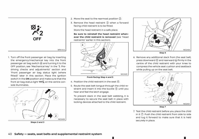
1. Turn off the front passenger air bag by insertingthe emergency/mechanical key into the frontpassenger air bag switchjA and turning it to theOFF position, see “Mechanical key” in the “3. Pre-driving checks and adjustments” section and“Front passenger air bag status light (wherefitted)” later in this section. Place the ignitionswitch in the ON position and make sure that thefront air bag status light on the centre con-sole illuminates.
2. Move the seat to the rearmost position ➁.
3. Remove the head restraint ➂ when a forwardfacing child restraint is to be fitted.
Store the head restraint in a safe place.
Be sure to reinstall the head restraint when-ever the child restraint is removed (see “Headrestraints” earlier in this section).
4. Position the child restraint in the seat ➃.
5. Route the seat belt tongue through the child re-straint and insert it into the buckle ➄ until youhear and feel the latch engage.
To prevent slack in the seat belt webbing, it isnecessary to secure the seat belt in place withlocking devices attached to the child restraint.
6. Remove any additional slack from the seat belt;press downward ➅ and rearwardj6a firmly in thecentre of the child restraint with your knee tocompress the vehicle seat cushion and seatbackwhile pulling up on the seat belt.
7. Test the child restraint before you place the childin it ➆. Push the child restraint from side to sideand tug it forward to make sure that it is heldsecurely in place.
NPA1412
NIC2428
Steps 2 and 3
NIC2429
Front-facing: Step 4 and 5
NIC2430
Step 6
NIC2431
Step 7
40 Safety — seats, seat belts and supplemental restraint system
8. Check to make sure that the child restraint isproperly secured prior to each use. If the childrestraint is loose, repeat steps 1 through 7.
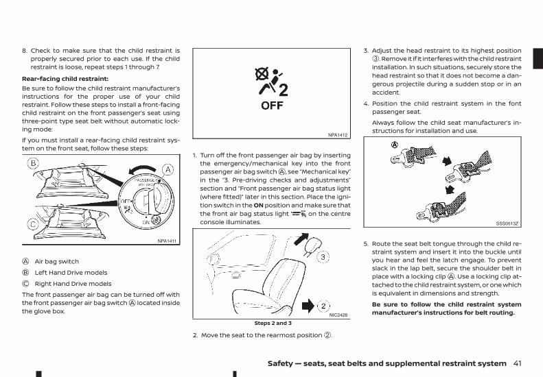
Rear-facing child restraint:Be sure to follow the child restraint manufacturer’sinstructions for the proper use of your childrestraint. Follow these steps to install a front-facingchild restraint on the front passenger’s seat usingthree-point type seat belt without automatic lock-ing mode:
If you must install a rear-facing child restraint sys-tem on the front seat, follow these steps:
jA Air bag switchjB Left Hand Drive modelsjC Right Hand Drive models
The front passenger air bag can be turned off withthe front passenger air bag switchjA located insidethe glove box.
1. Turn off the front passenger air bag by insertingthe emergency/mechanical key into the frontpassenger air bag switchjA , see “Mechanical key”in the “3. Pre-driving checks and adjustments”section and “Front passenger air bag status light(where fitted)” later in this section. Place the igni-tion switch in the ON position and make sure thatthe front air bag status light on the centreconsole illuminates.
2. Move the seat to the rearmost position ➁.
3. Adjust the head restraint to its highest position➂. Remove it if it interferes with the child restraintinstallation. In such situations, securely store thehead restraint so that it does not become a dan-gerous projectile during a sudden stop or in anaccident.
4. Position the child restraint system in the fontpassenger seat.
Always follow the child seat manufacturer’s in-structions for installation and use.
5. Route the seat belt tongue through the child re-straint system and insert it into the buckle untilyou hear and feel the latch engage. To preventslack in the lap belt, secure the shoulder belt inplace with a locking clipjA . Use a locking clip at-tached to the child restraint system, or one whichis equivalent in dimensions and strength.
Be sure to follow the child restraint systemmanufacturer’s instructions for belt routing.
NPA1411
NPA1412
NIC2428
Steps 2 and 3
SSS0513Z
Safety — seats, seat belts and supplemental restraint system 41
6. Test the child restraint before you place the childin it. Push the child restraint from side to side andtug it forward to make sure that it is held se-curely in place.
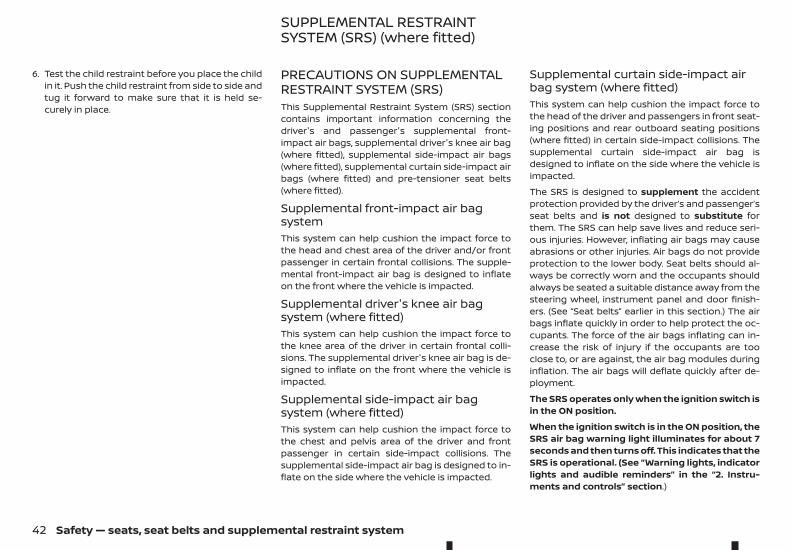
PRECAUTIONS ON SUPPLEMENTALRESTRAINT SYSTEM (SRS)This Supplemental Restraint System (SRS) sectioncontains important information concerning thedriver's and passenger's supplemental front-impact air bags, supplemental driver's knee air bag(where fitted), supplemental side-impact air bags(where fitted), supplemental curtain side-impact airbags (where fitted) and pre-tensioner seat belts(where fitted).
Supplemental front-impact air bagsystemThis system can help cushion the impact force tothe head and chest area of the driver and/or frontpassenger in certain frontal collisions. The supple-mental front-impact air bag is designed to inflateon the front where the vehicle is impacted.
Supplemental driver's knee air bagsystem (where fitted)This system can help cushion the impact force tothe knee area of the driver in certain frontal colli-sions. The supplemental driver's knee air bag is de-signed to inflate on the front where the vehicle isimpacted.
Supplemental side-impact air bagsystem (where fitted)This system can help cushion the impact force tothe chest and pelvis area of the driver and frontpassenger in certain side-impact collisions. Thesupplemental side-impact air bag is designed to in-flate on the side where the vehicle is impacted.
Supplemental curtain side-impact airbag system (where fitted)This system can help cushion the impact force tothe head of the driver and passengers in front seat-ing positions and rear outboard seating positions(where fitted) in certain side-impact collisions. Thesupplemental curtain side-impact air bag isdesigned to inflate on the side where the vehicle isimpacted.
The SRS is designed to supplement the accidentprotection provided by the driver’s and passenger’sseat belts and is not designed to substitute forthem. The SRS can help save lives and reduce seri-ous injuries. However, inflating air bags may causeabrasions or other injuries. Air bags do not provideprotection to the lower body. Seat belts should al-ways be correctly worn and the occupants shouldalways be seated a suitable distance away from thesteering wheel, instrument panel and door finish-ers. (See “Seat belts” earlier in this section.) The airbags inflate quickly in order to help protect the oc-cupants. The force of the air bags inflating can in-crease the risk of injury if the occupants are tooclose to, or are against, the air bag modules duringinflation. The air bags will deflate quickly after de-ployment.
The SRS operates only when the ignition switch isin the ON position.
When the ignition switch is in the ON position, theSRS air bag warning light illuminates for about 7seconds and then turns off. This indicates that theSRS is operational. (See “Warning lights, indicatorlights and audible reminders” in the “2. Instru-ments and controls” section.)
SUPPLEMENTAL RESTRAINTSYSTEM (SRS) (where fitted)
42 Safety — seats, seat belts and supplemental restraint system
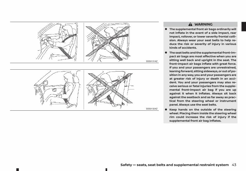
WARNING• The supplemental front air bags ordinarily will
not inflate in the event of a side impact, rearimpact, rollover, or lower severity frontal colli-sion. Always wear your seat belts to help re-duce the risk or severity of injury in variouskinds of accidents.
• The seat belts and the supplemental front-im-pact air bags are most effective when you aresitting well back and upright in the seat. Thefront-impact air bags inflate with great force.If you and your passengers are unrestrained,leaning forward, sitting sideways, or out of po-sition in any way, you and your passengers areat greater risk of injury or death in an acci-dent. You and your passengers may also re-ceive serious or fatal injuries from the supple-mental front-impact air bag if you are upagainst it when it inflates. Always sit backagainst the seatback and as far away as prac-tical from the steering wheel or instrumentpanel. Always use the seat belts.
• Keep hands on the outside of the steeringwheel. Placing them inside the steering wheelrim could increase the risk of injury if thesupplemental front air bag inflates.
SSS0131AZ
SSS0132AZ
Safety — seats, seat belts and supplemental restraint system 43
SSS0006Z
SSS0007Z
SSS0008Z
SSS0009Z
SSS0099Z
SSS0100Z
44 Safety — seats, seat belts and supplemental restraint system
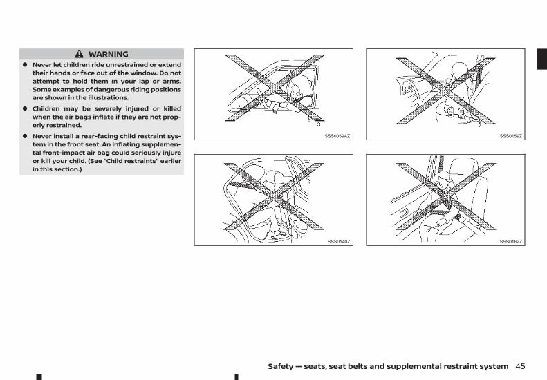
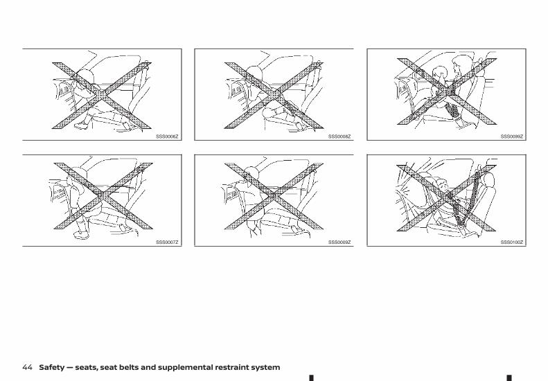
WARNING• Never let children ride unrestrained or extend
their hands or face out of the window. Do notattempt to hold them in your lap or arms.Some examples of dangerous riding positionsare shown in the illustrations.
• Children may be severely injured or killedwhen the air bags inflate if they are not prop-erly restrained.
• Never install a rear-facing child restraint sys-tem in the front seat. An inflating supplemen-tal front-impact air bag could seriously injureor kill your child. (See “Child restraints” earlierin this section.)
SSS0059AZ
SSS0140Z
SSS0159Z
SSS0162Z
Safety — seats, seat belts and supplemental restraint system 45
WARNING• The supplemental side-impact air bags
(where fitted) and supplemental curtain side-impact air bags (where fitted) ordinarily willnot inflate in the event of a front impact, rearimpact, rollover, or lower severity side colli-sion. Always wear the seat belts to help reducethe risk or severity of injury in accidents.
• The seat belts and the supplemental side-im-pact air bags and supplemental curtain side-impact air bags are most effective when youare sitting well back and upright in the seat.The supplemental side-impact air bags andsupplemental curtain side-impact air bags in-flate with great force. If you and your passen-gers are unrestrained, leaning forward, sittingsideways, or out of position in any way, youand your passengers are at greater risk of in-jury or death in an accident.
• Do not allow anyone to place their hands, legsor face near the supplemental side-impact airbags and supplemental curtain side-impactair bags located on the sides of the seatbackof the front seats or near the side roof rails. Donot allow anyone sitting in the front seats orrear outboard seats to extend their hands outof the windows or lean against the doors.Some examples of dangerous riding positionsare shown in the illustrations.
• When sitting in the rear seats, do not hold ontothe seatback of the front seats. If the supple-mental side-impact air bags and supplemen-tal curtain side-impact air bags inflate, youmay be seriously injured. Be especially carefulwith children, who should always be properlyrestrained.
• Do not use seat covers on the front seatbacks.They may interfere with the supplementalside-impact air bag inflations.
• Do not attach the key with heavy objects, hardobjects or objects with sharp edges. This maycause injury if the supplemental knee air baginflates.
Pre-tensioner seat belt system(where fitted)The pre-tensioner seat belt system may activatewith the supplemental air bag system in certaintypes of collisions. Working with the front seat beltretractors and anchors, it helps tighten the seat beltthe instant the vehicle becomes involved in certaintypes of collisions, helping to restrain front seat oc-cupants. (See “Seat belts” earlier in this section.)
Air bag warning labels
➀ SRS air bag warning label: The warning label islocated on the surface of the front passengersun visor.
➁ SRS front passenger air bag warning label: Thewarning label is located on the outer side ofthe instrument panel (passenger side).
➂ SRS side air bag warning label: The warninglabel is located on the side of the passengerside centre pillar. Tags are also sewn into thefront seat covers.
NPA1155
46 Safety — seats, seat belts and supplemental restraint system
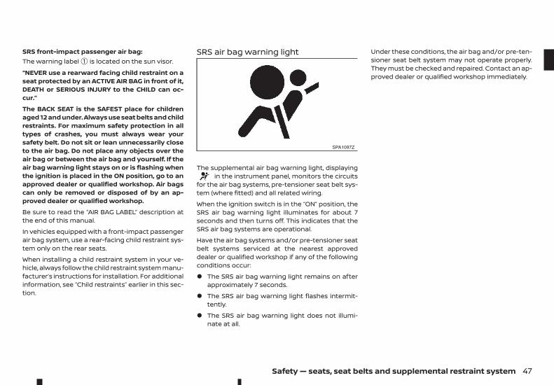
SRS front-impact passenger air bag:The warning label ➀ is located on the sun visor.
“NEVER use a rearward facing child restraint on aseat protected by an ACTIVE AIR BAG in front of it,DEATH or SERIOUS INJURY to the CHILD can oc-cur.”
The BACK SEAT is the SAFEST place for childrenaged 12 and under. Always use seat belts and childrestraints. For maximum safety protection in alltypes of crashes, you must always wear yoursafety belt. Do not sit or lean unnecessarily closeto the air bag. Do not place any objects over theair bag or between the air bag and yourself. If theair bag warning light stays on or is flashing whenthe ignition is placed in the ON position, go to anapproved dealer or qualified workshop. Air bagscan only be removed or disposed of by an ap-proved dealer or qualified workshop.
Be sure to read the “AIR BAG LABEL” description atthe end of this manual.
In vehicles equipped with a front-impact passengerair bag system, use a rear-facing child restraint sys-tem only on the rear seats.
When installing a child restraint system in your ve-hicle, always follow the child restraint system manu-facturer’s instructions for installation. For additionalinformation, see “Child restraints” earlier in this sec-tion.
SRS air bag warning light
The supplemental air bag warning light, displayingin the instrument panel, monitors the circuits
for the air bag systems, pre-tensioner seat belt sys-tem (where fitted) and all related wiring.
When the ignition switch is in the “ON” position, theSRS air bag warning light illuminates for about 7seconds and then turns off. This indicates that theSRS air bag systems are operational.
Have the air bag systems and/or pre-tensioner seatbelt systems serviced at the nearest approveddealer or qualified workshop if any of the followingconditions occur:
• The SRS air bag warning light remains on afterapproximately 7 seconds.
• The SRS air bag warning light flashes intermit-tently.
• The SRS air bag warning light does not illumi-nate at all.
Under these conditions, the air bag and/or pre-ten-sioner seat belt system may not operate properly.They must be checked and repaired. Contact an ap-proved dealer or qualified workshop immediately.
SPA1097Z
Safety — seats, seat belts and supplemental restraint system 47
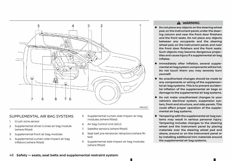
SUPPLEMENTAL AIR BAG SYSTEMS1. Crush zone sensor
2. Supplemental driver's knee air bag module(where fitted)
3. Supplemental front air bag modules
4. Supplemental curtain side-impact air baginflators (where fitted)
5. Supplemental curtain side-impact air bagmodules (where fitted)
6. Air bag Control Unit (ACU)
7. Satellite sensors (where fitted)
8. Seat belt pre-tensioner retractors (where fit-ted)
9. Supplemental side-impact air bag modules(where fitted)
WARNING• Do not place any objects on the steering wheel
pad, on the instrument panel, under the steer-ing column and near the front door finishersand the front seats. Do not place any objectsbetween any occupants and the steeringwheel pad, on the instrument panel, and nearthe front door finishers and the front seats.Such objects may become dangerous projec-tiles and cause injury if a supplemental air baginflates.
• Immediately after inflation, several supple-mental air bag system components will be hot.Do not touch them: you may severely burnyourself.
• No unauthorised changes should be made toany components or wiring of the supplemen-tal air bag systems. This is to prevent acciden-tal inflation of the supplemental air bags ordamage to the supplemental air bag systems.
• Do not make unauthorised changes to yourvehicle’s electrical system, suspension sys-tem, front end structure, and side panels. Thiscould affect proper operation of the supple-mental air bag systems.
• Tampering with the supplemental air bag sys-tems may result in serious personal injury.Tampering includes changes to the steeringwheel and the instrument panel by placingmaterials over the steering wheel pad andabove, around or on the instrument panel orby installing additional trim materials aroundthe supplemental air bag systems.
NPA1527
48 Safety — seats, seat belts and supplemental restraint system
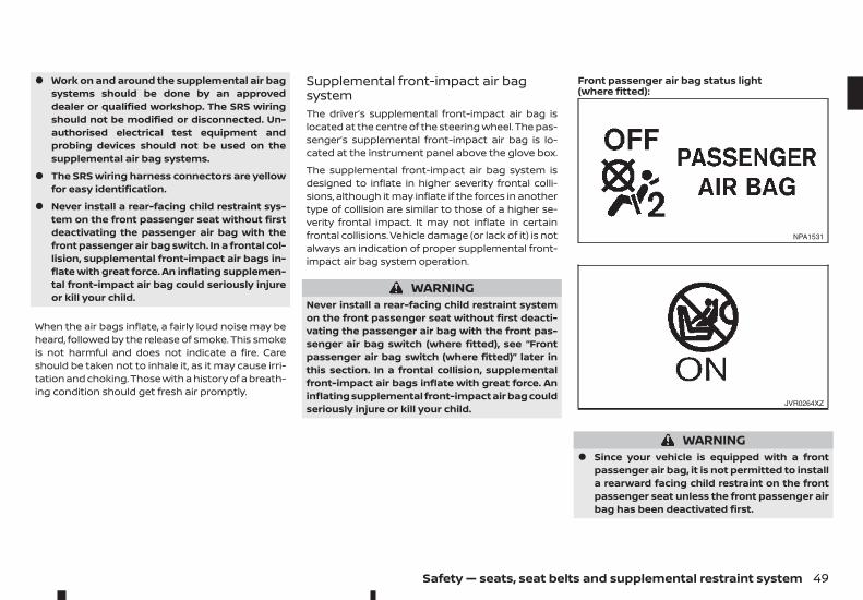
• Work on and around the supplemental air bagsystems should be done by an approveddealer or qualified workshop. The SRS wiringshould not be modified or disconnected. Un-authorised electrical test equipment andprobing devices should not be used on thesupplemental air bag systems.
• The SRS wiring harness connectors are yellowfor easy identification.
• Never install a rear-facing child restraint sys-tem on the front passenger seat without firstdeactivating the passenger air bag with thefront passenger air bag switch. In a frontal col-lision, supplemental front-impact air bags in-flate with great force. An inflating supplemen-tal front-impact air bag could seriously injureor kill your child.
When the air bags inflate, a fairly loud noise may beheard, followed by the release of smoke. This smokeis not harmful and does not indicate a fire. Careshould be taken not to inhale it, as it may cause irri-tation and choking. Those with a history of a breath-ing condition should get fresh air promptly.
Supplemental front-impact air bagsystemThe driver’s supplemental front-impact air bag islocated at the centre of the steering wheel. The pas-senger’s supplemental front-impact air bag is lo-cated at the instrument panel above the glove box.
The supplemental front-impact air bag system isdesigned to inflate in higher severity frontal colli-sions, although it may inflate if the forces in anothertype of collision are similar to those of a higher se-verity frontal impact. It may not inflate in certainfrontal collisions. Vehicle damage (or lack of it) is notalways an indication of proper supplemental front-impact air bag system operation.
WARNINGNever install a rear-facing child restraint systemon the front passenger seat without first deacti-vating the passenger air bag with the front pas-senger air bag switch (where fitted), see “Frontpassenger air bag switch (where fitted)” later inthis section. In a frontal collision, supplementalfront-impact air bags inflate with great force. Aninflating supplemental front-impact air bag couldseriously injure or kill your child.
Front passenger air bag status light(where fitted):
WARNING• Since your vehicle is equipped with a front
passenger air bag, it is not permitted to installa rearward facing child restraint on the frontpassenger seat unless the front passenger airbag has been deactivated first.
NPA1531
JVR0264XZ
Safety — seats, seat belts and supplemental restraint system 49
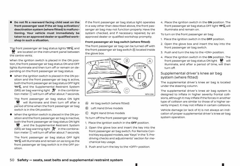
• Do not fit a rearward facing child seat on thefront passenger seat if the air bag activation/deactivation system (where fitted) is malfunc-tioning. Your vehicle must immediately betaken to an approved dealer or qualified work-shop in such a situation.
The front passenger air bag status lights andare located on the instrument panel between
the centre vents.
When the ignition switch is placed in the ON posi-tion, the front passenger air bag status ON and OFFlights illuminate and then turn off or remain on de-pending on the front passenger air bag status.
• When the ignition switch is placed in the ON po-sition and the front passenger air bag is active,both the front passenger air bag status OFF light
, and the Supplemental Restraint System(SRS) air bag warning light in the combina-tion meter ➀ will turn off after about 7 seconds.
The front passenger air bag status ON lightwill illuminate and then turn off after a
period of time when the front passenger air bagswitch is in the ON position.
• When the ignition switch is placed in the ON po-sition and the front passenger air bag is inactive,both the front passenger air bag status ON light
, and the Supplemental Restraint System(SRS) air bag warning light in the combina-tion meter ➀ will turn off after about 7 seconds.
The front passenger air bag status OFF lightwill illuminate and remain on as long as the
front passenger air bag switch is in the OFF po-sition.
If the front passenger air bag status light operatesin a way other than described above, the front pas-senger air bag may not function properly. Have thesystem checked, and if necessary repaired, by anapproved dealer or qualified workshop promptly.
Front passenger air bag switch (where fitted):The front passenger air bag can be turned off withthe front passenger air bag switchjA located insidethe glove box.
jA Air bag switch (where fitted)jB Left Hand Drive modelsjC Right Hand Drive models
To turn off the front passenger air bag:
1. Place the ignition switch in the OFF position.
2. Open the glove box and insert the key into thefront passenger air bag switch. For Remote Con-trol Key equipped models, see “Keys” in the “3. Pre-driving checks and adjustments” section for me-chanical key usage.
3. Push and turn the key to the <OFF> position.
4. Place the ignition switch in the ON position. Thefront passenger air bag status OFF light willilluminate and remain on.
To turn on the front passenger air bag:
1. Place the ignition switch in the OFF position.
2. Open the glove box and insert the key into thefront passenger air bag switch.
3. Push and turn the key to the <ON> position.
4. Place the ignition switch in the ON position. Thefront passenger air bag status ON light willilluminate, and after a period of time, will thenturn off.
Supplemental driver's knee air bagsystem (where fitted)The supplemental driver's knee air bag is locatedunder the steering column.
The supplemental driver's knee air bag system isdesigned to inflate in higher severity frontal colli-sions, although it may inflate if the forces in anothertype of collision are similar to those of a higher se-verity impact. It may not inflate in certain collisions.
Vehicle damage (or lack of it) is not always an indi-cation of proper supplemental driver's knee air bagsystem operation.
NPA1296
50 Safety — seats, seat belts and supplemental restraint system
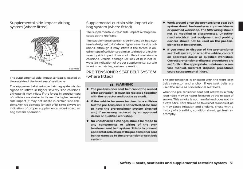
Supplemental side-impact air bagsystem (where fitted)
The supplemental side-impact air bag is located atthe outside of the front seats’ seatbacks.
The supplemental side-impact air bag system is de-signed to inflate in higher severity side collisions,although it may inflate if the forces in another typeof collision are similar to those of a higher severityside impact. It may not inflate in certain side colli-sions. Vehicle damage (or lack of it) is not always anindication of proper supplemental side-impact airbag system operation.
Supplemental curtain side-impact airbag system (where fitted)The supplemental curtain side-impact air bag is lo-cated at the roof rails.
The supplemental curtain side-impact air bag sys-tem is designed to inflate in higher severity side col-lisions, although it may inflate if the forces in an-other type of collision are similar to those of a higherseverity side impact. It may not inflate in certain sidecollisions. Vehicle damage (or lack of it) is not al-ways an indication of proper supplemental curtainside-impact air bag system operation.
PRE-TENSIONER SEAT BELT SYSTEM(where fitted)
WARNING• The pre-tensioner seat belt cannot be reused
after activation. It must be replaced togetherwith the retractor and buckle as a unit.
• If the vehicle becomes involved in a collisionbut the pre-tensioner is not activated, be sureto have the pre-tensioner system checkedand, if necessary, replaced by an approveddealer or qualified workshop.
• No unauthorised changes should be made toany components or wiring of the pre-tensioner seat belt system. This is to preventaccidental activation of the pre-tensioner seatbelt or damage to the pre-tensioner seat beltsystem.
• Work around or on the pre-tensioner seat beltsystem should be done by an approved dealeror qualified workshop. The SRS wiring shouldnot be modified or disconnected. Unautho-rised electrical test equipment and probingdevices should not be used on the pre-ten-sioner seat belt system.
• If you need to dispose of the pre-tensionerseat belt system, or scrap the vehicle, contactan approved dealer or qualified workshop.Correct pre-tensioner disposal procedures areset forth in the appropriate maintenance ser-vice manual. Incorrect disposal procedurescould cause personal injury.
The pre-tensioner is encased with the front seatbelt’s retractor and anchor. These seat belts areused the same as conventional seat belts.
When the pre-tensioner seat belt activates, a fairlyloud noise may be heard, followed by the release ofsmoke. This smoke is not harmful and does not in-dicate a fire. Care should be taken not to inhale it, asit may cause irritation and choking. Those with ahistory of a breathing condition should get fresh airpromptly.
SSS1092Z
Safety — seats, seat belts and supplemental restraint system 51
REPAIR AND REPLACEMENTPROCEDURE
WARNING• Once the supplemental front-impact air bags
have been inflated, the air bag modules willnot function and must be replaced. The air bagmodules must be replaced by an approveddealer or qualified workshop. The inflated airbag modules cannot be repaired.
• The air bag systems should be inspected byan approved dealer or qualified workshop ifthere is any damage to the vehicle.
• If you need to dispose of the SRS or scrap thevehicle, contact an approved dealer or quali-fied workshop. Correct disposal proceduresare set forth in the appropriate maintenanceservice manual. Incorrect disposal procedurescould cause personal injury.
The supplemental front-impact air bags and pre-tensioner seat belts (where fitted) are designed toactivate on a one-time-only basis. As a reminder,unless the SRS air bag warning light is damaged,the SRS air bag warning light remains illuminatedafter inflation has occurred. The repair and replace-ment of the SRS should be done only by an ap-proved dealer or qualified workshop.
When maintenance work is required on the vehicle,information about the air bags, pre-tensioner seatbelts and related parts should be pointed out to theperson performing the maintenance. The ignitionswitch should always be in the “LOCK” positionwhen working under the bonnet or inside the ve-hicle.
52 Safety — seats, seat belts and supplemental restraint system
2 Instruments and controlsInstruments and controls
Meters and gauges..................................................................................... 54Speedometer and Fuel gauge ................................................... 54Tachometer and Engine coolant temperaturegauge............................................................................................................ 55Instrument brightness control.................................................. 56
Warning lights, indicator lights and audiblereminders........................................................................................................... 57
Checking lights...................................................................................... 58Warning lights ........................................................................................ 58Indicator lights....................................................................................... 62Audible reminders............................................................................... 64
Vehicle information display.................................................................. 65How to use the Vehicle Information Display................... 65Settings ....................................................................................................... 65Trip computer......................................................................................... 70Indicators for operation.................................................................. 73Oil control system (where fitted).............................................. 76Clock and outside air temperature (wherefitted)............................................................................................................. 77
Headlight and turn signal switch..................................................... 78Headlight switch................................................................................... 78Headlight aiming control (where fitted) ............................. 79Battery saver system (where fitted) ...................................... 79Turn signal switch ............................................................................... 79
Fog light switch (where fitted) ........................................................... 80Front fog lights (where fitted) .................................................... 80Rear fog light (where fitted)......................................................... 80
Wiper and washer switch ...................................................................... 81Windscreen wiper and washer switch................................. 81
Defogger switch (where fitted).......................................................... 82Headlight cleaner (where fitted)....................................................... 83
Headlight cleaner switch (where fitted) ............................. 83Horn ....................................................................................................................... 83Windows ............................................................................................................. 84
Manual windows (where fitted) ................................................ 84Power windows (where fitted)................................................... 84
Power outlets.................................................................................................. 85Storage ................................................................................................................ 86
Glove box.................................................................................................... 86Console box ............................................................................................. 87Sunglasses holder............................................................................... 87Console side pockets........................................................................ 87Cup holders (where fitted) ............................................................ 87Roof rails (where fitted) ................................................................... 88Card holder (where fitted)............................................................. 88
Sun visors........................................................................................................... 89Sunroof (where fitted) .............................................................................. 89
Automatic sunroof.............................................................................. 89Interior lights................................................................................................... 90
Room light control switches ....................................................... 90Console light (where fitted).......................................................... 91Map lights .................................................................................................. 91Map light control switch (where fitted)............................... 91Room light (where fitted)............................................................... 92Rear personal light (where fitted)............................................ 92Vanity mirror lights (where fitted) ........................................... 92Battery saver system........................................................................ 93
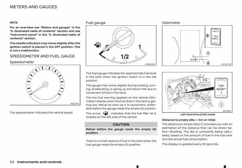
NOTE
For an overview see “Meters and gauges” in the“0. Illustrated table of contents” section and see“Instrument panel” in the “0. Illustrated table ofcontents” section.
The needle indicators may move slightly after theignition switch is placed in the OFF position. Thisis not a malfunction.
SPEEDOMETER AND FUEL GAUGESpeedometer
The speedometer indicates the vehicle speed.
Fuel gauge
The fuel gauge indicates the approximate fuel levelin the tank when the ignition switch is in the ONposition.
The gauge may move slightly during braking, turn-ing, accelerating, or going up and down hills due tomovement of fuel in the tank.
The low fuel warning appears on the vehicle infor-mation display when the fuel level in the tank is get-ting low. Refuel as soon as it is convenient, prefer-ably before the gauge reads the empty (0) position.
The arrow, , indicates that the fuel filler lid islocated on the left side of the vehicle.
CAUTIONRefuel before the gauge reads the empty (0)position.
There is a small reserve of fuel in the tank when thefuel gauge reads the empty (0) position.
Odometer
Distance to empty (dte — km or mile):The distance to empty (dte) ➀ provides you with anestimation of the distance that can be driven be-fore refuelling. The dte is constantly being calcu-lated, based on the amount of fuel in the fuel tankand the actual fuel consumption.
The display is updated every 30 seconds.
NIC2704
JVI0602XZ JVI1041XZ
NIC3094
Left Hand Drive (LHD) model
METERS AND GAUGES
54 Instruments and controls
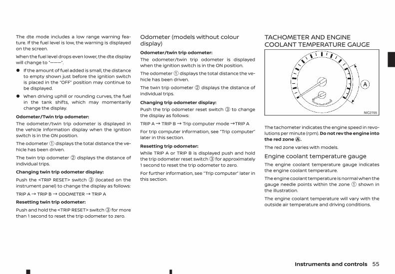
The dte mode includes a low range warning fea-ture. If the fuel level is low, the warning is displayedon the screen.
When the fuel level drops even lower, the dte displaywill change to “———”.
• If the amount of fuel added is small, the distanceto empty shown just before the ignition switchis placed in the “OFF” position may continue tobe displayed.
• When driving uphill or rounding curves, the fuelin the tank shifts, which may momentarilychange the display.
Odometer/Twin trip odometer:The odometer/twin trip odometer is displayed inthe vehicle information display when the ignitionswitch is in the ON position.
The odometer ➀ displays the total distance the ve-hicle has been driven.
The twin trip odometer ➁ displays the distance ofindividual trips.
Changing twin trip odometer display:
Push the <TRIP RESET> switch ➂ (located on theinstrument panel) to change the display as follows:
TRIP A! TRIP B! ODOMETER! TRIP A
Resetting twin trip odometer:
Push and hold the <TRIP RESET> switch ➂ for morethan 1 second to reset the trip odometer to zero.
Odometer (models without colourdisplay)Odometer/twin trip odometer:The odometer/twin trip odometer is displayedwhen the ignition switch is in the ON position.
The odometer ➀ displays the total distance the ve-hicle has been driven.
The twin trip odometer ➁ displays the distance ofindividual trips.
Changing trip odometer display:Push the trip odometer reset switch ➂ to changethe display as follows:
TRIP A! TRIP B! Trip computer mode!TRIP A
For trip computer information, see “Trip computer”later in this section.
Resetting trip odometer:While TRIP A or TRIP B is displayed push and holdthe trip odometer reset switch ➂ for approximately1 second to reset the trip odometer to zero.
For further information, see “Trip computer” later inthis section.
TACHOMETER AND ENGINECOOLANT TEMPERATURE GAUGE
The tachometer indicates the engine speed in revo-lutions per minute (rpm). Do not rev the engine intothe red zonejA .
The red zone varies with models.
Engine coolant temperature gaugeThe engine coolant temperature gauge indicatesthe engine coolant temperature.
The engine coolant temperature is normal when thegauge needle points within the zone ➀ shown inthe illustration.
The engine coolant temperature will vary with theoutside air temperature and driving conditions.
NIC2705
Instruments and controls 55
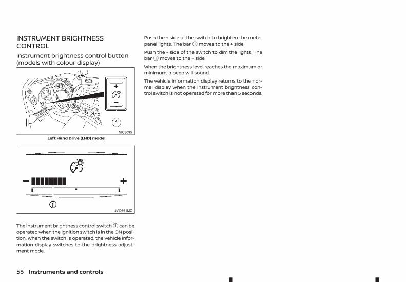
INSTRUMENT BRIGHTNESSCONTROLInstrument brightness control button(models with colour display)
The instrument brightness control switch ➀ can beoperated when the ignition switch is in the ON posi-tion. When the switch is operated, the vehicle infor-mation display switches to the brightness adjust-ment mode.
Push the + side of the switch to brighten the meterpanel lights. The bar ➀ moves to the + side.
Push the - side of the switch to dim the lights. Thebar ➀ moves to the − side.
When the brightness level reaches the maximum orminimum, a beep will sound.
The vehicle information display returns to the nor-mal display when the instrument brightness con-trol switch is not operated for more than 5 seconds.
NIC3095
Left Hand Drive (LHD) model
JVI0661MZ
56 Instruments and controls
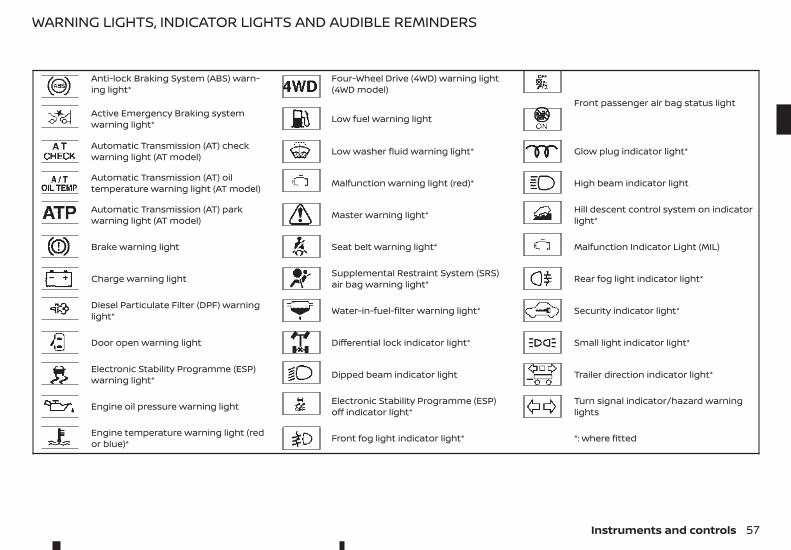
Anti-lock Braking System (ABS) warn-ing light*
Four-Wheel Drive (4WD) warning light(4WD model)
Front passenger air bag status lightActive Emergency Braking systemwarning light* Low fuel warning light
Automatic Transmission (AT) checkwarning light (AT model) Low washer fluid warning light* Glow plug indicator light*
Automatic Transmission (AT) oiltemperature warning light (AT model) Malfunction warning light (red)* High beam indicator light
Automatic Transmission (AT) parkwarning light (AT model) Master warning light* Hill descent control system on indicator
light*
Brake warning light Seat belt warning light* Malfunction Indicator Light (MIL)
Charge warning light Supplemental Restraint System (SRS)air bag warning light* Rear fog light indicator light*
Diesel Particulate Filter (DPF) warninglight* Water-in-fuel-filter warning light* Security indicator light*
Door open warning light Differential lock indicator light* Small light indicator light*
Electronic Stability Programme (ESP)warning light* Dipped beam indicator light Trailer direction indicator light*
Engine oil pressure warning light Electronic Stability Programme (ESP)off indicator light*
Turn signal indicator/hazard warninglights
Engine temperature warning light (redor blue)* Front fog light indicator light* *: where fitted
WARNING LIGHTS, INDICATOR LIGHTS AND AUDIBLE REMINDERS
Instruments and controls 57
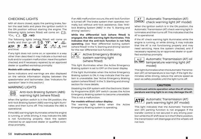
CHECKING LIGHTSWith all doors closed, apply the parking brake, fas-ten the seat belts and place the ignition switch inthe ON position without starting the engine. Thefollowing lights (where fitted) will come on: ,
, , , .
The following lights (where fitted) will come onbriefly and then go off: , , , ,
, , , , , , , (redand blue)
If any light does not come on, or operates in a wayother than described it may indicate a burned-outbulb and/or a system malfunction. Have the systemchecked, and if necessary repaired, by an approveddealer or qualified workshop promptly.
Models with colour display:
Some indicators and warnings are also displayedon the vehicle information display between thespeedometer and tachometer. (See “Indicators foroperation” later in this section.)
WARNING LIGHTSAnti-lock Braking System (ABS)warning light (where fitted)
When the ignition switch is in the ON position, theAnti-lock Braking System (ABS) warning light illumi-nates and then turns off. This indicates the ABS isoperational.
If the ABS warning light illuminates while the engineis running, or while driving, it may indicate the ABSis not functioning properly. Have the systemchecked by an approved dealer or qualified work-shop promptly.
If an ABS malfunction occurs, the anti-lock functionis turned off. The brake system then operates nor-mally, but without anti-lock assistance. (See “Anti-lock Braking System (ABS)” in the “5. Starting anddriving” section.)
While the differential lock (where fitted) isengaged, the ABS warning light illuminates. Thisindicates that the anti-lock function is not fullyoperating. (See “Rear differential locking system(where fitted)” in the “5. Starting and driving” sectionfor the rear differential lock function.)
Active Emergency Brakingsystem warning light(where fitted)
This light illuminates when the Active EmergencyBraking system is set to OFF on the lower display.
If the light illuminates when the Active EmergencyBraking system is ON, it may indicate that the sys-tem is unavailable. See “Active Emergency Brakingsystem (where fitted)” in the “5. Starting and driving”section for more details.
Disabling the ESP system with the Electronic Stabil-ity Programme (ESP) OFF switch causes the ActiveEmergency Braking system to become unavailable.This is not a malfunction.
For models without colour display:The warning light blinks when the ActiveEmergency Braking system is operating.
Automatic Transmission (AT)check warning light (AT model)
When the ignition switch is in the ON position, theAutomatic Transmission (AT) check warning light il-luminates and then turns off. This indicates that theAT is operational.
If the AT check warning light illuminates while theengine is running, or while driving, it may indicatethat the AT is not functioning properly and mayneed servicing. Have the system checked, and ifnecessary repaired, by an approved dealer or quali-fied workshop promptly.
Automatic Transmission (AT) oiltemperature warning light (ATmodel)
This light illuminates when the Automatic Transmis-sion (AT) oil temperature is too high. If the light illu-minates while driving, reduce the vehicle speed assoon as safely possible until the light turns off.
CAUTIONContinued vehicle operation when the AT oil tem-perature warning light is on may damage the AT.
Automatic Transmission (AT)park warning light (AT model)
This light indicates that the Automatic Transmis-sion (AT) parking function is not engaged. If thetransfer control is not secured in any driving posi-tion while the AT shift lever is in the P (Park) position,the transmission will disengage and the wheels willnot lock.
58 Instruments and controls
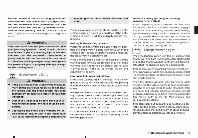
For 4WD model: If the ATP warning light illumi-nates with the shift lever in the P (Park) position,shift the Four-Wheel Drive (4WD) mode switch tothe 2WD, 4H or 4LO position again with the shiftlever in the N (Neutral) position. (See “4WD modeswitch operation” in the “5. Starting and driving” sec-tion.)
WARNINGIf the 4WD mode indicator (see “Four-Wheel Drive(4WD) warning light (4WD model)” later in this sec-tion) is OFF or the ATP warning light is ON, thisindicates that the automatic transmission P(Park) position will not function and could resultin the vehicle moving unexpectedly, causing seri-ous personal injury or property damage. Alwaysset the parking brake.
Brake warning light
WARNING• If the brake fluid level is below the minimum
mark on the brake fluid reservoir, do not drivethe vehicle until the brake system has beenchecked by an approved dealer or qualifiedworkshop.
• Even if you judge it to be safe, have your ve-hicle towed because driving it could be dan-gerous.
• Depressing the brake pedal without the en-gine running and/or with a low brake fluidlevel could increase the stopping distance and
require greater pedal travel distance andeffort.
The brake warning light indicates the parking brakesystem operation, a low brake fluid level of the brakesystem and an Anti-lock Braking System (ABS) mal-function.
Parking brake warning indicator:When the ignition switch is placed in the ON posi-tion, the brake warning light illuminates. When theengine is started and the parking brake is released,the brake warning light turns off.
If the parking brake is not fully released, the brakewarning light remains on. Be sure that the brakewarning light has turned off before driving. (See“Parking brake” in the “3. Pre-driving checks andadjustments” section.)
Low brake fluid warning indicator:If the brake warning light illuminates while the en-gine is running, or while driving, and the parkingbrake is released, it may indicate the brake fluid levelis low.
When the brake warning light illuminates while driv-ing, stop the vehicle safely as soon as possible. Stopthe engine and check the brake fluid level. If thebrake fluid level is at the minimum mark, add brakefluid as necessary. (See “Brake fluid” in the “8. Main-tenance and do-it-yourself” section.)
If the brake fluid level is sufficient, have the brakesystem checked by an approved dealer or qualifiedworkshop promptly.
Anti-lock Braking System (ABS) warningindicator (where fitted):When the parking brake is released and the brakefluid level is sufficient, if both the brake warning lightand the Anti-lock Braking System (ABS) warninglight illuminate, it may indicate the ABS is not func-tioning properly. Have the brake system checked,and if necessary repaired, by an approved dealer orqualified workshop promptly. (See “Brake system” inthe “5. Starting and driving” section.)
Charge warning light
When the ignition switch is in the ON position, thecharge warning light illuminates. After starting theengine, the charge warning light turns off. This indi-cates that the charging system is operational.
If the charge warning light illuminates while the en-gine is running, or while driving, it may indicate thatthe charging system is not functioning properly andmay need servicing.
When the charge warning light illuminates whiledriving, stop the vehicle safely as soon as possible.Stop the engine and check the alternator belt. If thealternator belt is loose, broken or missing, contactan approved dealer or qualified workshop promptly.(See “Drive belt” in the “8. Maintenance anddo-it-yourself” section.)
If the alternator belt appears to be functioning cor-rectly but the charge warning light remains illumi-nated, have the charging system checked by an ap-proved dealer or qualified workshop promptly.
Instruments and controls 59
CAUTIONDo not continue driving if the alternator belt isloose, broken or missing.
Diesel Particulate Filter (DPF)warning light (where fitted)
When the DPF warning light illuminates, it indicatesthat particulate matter is accumulated to the speci-fied amount of the limit in the filter and the filterneeds to regenerate. For filter regeneration details,see “Diesel Particulate Filter (DPF) (where fitted)” inthe “5. Starting and driving” section.
CAUTIONIf you continue driving with the DPF warning lighton without performing the filter regeneration,this will lead to particulate matter overload in thefilter.
If this occurs, then the Malfunction Indicator Light(MIL) will turn on. The performance of the enginemight be limited to protect the DPF system. Seean approved dealer or qualified workshop to per-form the service regeneration.
Door open warning light
When the ignition switch is in the ON position, thedoor open warning light illuminates if any of thedoors are open or not closed securely.
Electronic Stability Programme(ESP) warning light(where fitted)
When the ignition switch is in the ON position, theElectronic Stability Programme (ESP) warning lightilluminates and then turns off.
The warning light blinks when the ESP system isoperating.
When the warning light blinks while driving, the driv-ing condition is slippery and the vehicle’s tractionlimit is about to be exceeded.
If the ESP warning light illuminates while the engineis running or while driving, it may indicate that theESP system is not functioning properly and mayneed servicing. Have the system checked, and ifnecessary repaired, by an approved dealer or quali-fied workshop promptly. If a malfunction occurs, theESP function is turned off, but the vehicle is still driv-able. (See “Electronic Stability Programme (ESP) sys-tem (where fitted)” in the “5. Starting and driving”section.)
Engine oil pressure warninglight
When the ignition switch is in the ON position, theengine oil pressure warning light illuminates. Afterstarting the engine, the engine oil pressure warninglight turns off. This indicates that the oil pressuresensors in the engine are operational.
If the engine oil pressure warning light illuminatesor blinks while the engine is running, it may indicatethat the engine oil pressure is low.
Stop the vehicle safely as soon as possible. Stop theengine immediately and call an approved dealer orqualified workshop.
CAUTION• Running the engine with the engine oil pres-
sure warning light illuminated could cause se-rious damage to the engine.
• The engine oil pressure warning light is notdesigned to indicate a low oil level. The oil levelshould be checked using the dipstick. (See“Checking engine oil level” in the “8. Mainte-nance and do-it-yourself” section.)
Engine temperature warninglight (red/blue) (where fitted)
High temperature indicator light (red):The red warning light comes on when the engineoverheats.
WARNINGIf the high temperature warning light illuminateswhile the engine is running, it may indicate theengine temperature is extremely high. Stop thevehicle safely as soon as possible. If the vehicle isoverheated, continuing vehicle operation may se-riously damage the engine.
• If the engine coolant temperature warninglight (red) comes on while driving, stop the ve-hicle as soon as possible and contact an ap-proved dealer or qualified workshop.
60 Instruments and controls
• When towing a trailer or driving uphill, reducethe vehicle speed as soon as safely possible todecrease the engine coolant temperature.
• If the engine overheats, continued operationof the vehicle may seriously damage the en-gine. See “If your vehicle overheats” in the “6. Incase of emergency” section for immediate re-quired action.
Low temperature indicator light (blue):When the ignition switch is placed in the ON posi-tion, the engine temperature warning light (blue)comes on. After a few seconds, it should go out andremain off while the engine is running.
Four-Wheel Drive (4WD)warning light (4WD model)
When the ignition switch is in the ON position, theFour-Wheel Drive (4WD) warning light illuminates.After starting the engine, the 4WD warning lightturns off.
If the 4WD system malfunctions or the revolution orradius of the front and the rear wheel differs, thewarning light will either remain illuminated or blink.(See “Four-Wheel Drive (4WD) (where fitted)” in the“5. Starting and driving” section.)
CAUTION• If the 4WD warning light illuminates or blinks
while driving, reduce the vehicle speed andhave your vehicle checked by an approveddealer or qualified workshop as soon as pos-sible.
• If the Four-Wheel Drive (4WD) warning lightturns on when driving on dry hard surfaceroads:
– in the 4H position, shift the 4WD modeswitch to 2WD.
– in the 4LO position, stop the vehicle andshift the transmission lever to the N (Neu-tral) position with the brake pedaldepressed and shift the 4WD mode switchto 2WD.
If the warning light is still on after the above opera-tions, have your vehicle checked by an approveddealer or qualified workshop as soon as possible.
Low fuel warning light
The low fuel warning light illuminates when the fuellevel in the tank is getting low. Refuel as soon as it isconvenient, preferably before the fuel gaugereaches the empty (0) position.
There will be a small reserve of fuel remaining inthe tank when the fuel gauge reaches the empty(0) position.
Low washer fluid warning light(where fitted)
The low washer fluid warning light illuminates whenthe washer fluid in the reservoir is at a low level. Addwasher fluid as necessary. (See “Window washerfluid” in the “8. Maintenance and do-it-yourself” sec-tion.)
Malfunction warning light (red)(where fitted)
When the ignition switch is placed in the ON posi-tion, the malfunction warning light illuminates inred. This means that the system is operational. Af-ter starting the engine, the warning light turns off.
For the orange Malfunction Indicator Light (MIL), see“Malfunction Indicator Light (MIL)” later in this sec-tion for details.
If the malfunction warning light (red) illuminatescontinuously while the engine is running, it may in-dicate an engine control system malfunction. Haveyour vehicle inspected by an approved dealer orqualified workshop. You do not need to have yourvehicle towed to the dealer.
CAUTIONContinuing vehicle operation without proper ser-vicing of the engine control system could lead topoor driveability, reduced fuel economy, anddamage to the engine control system, which mayaffect the vehicle’s warranty coverage.
Master warning light(where fitted)
When the ignition switch is in the ON position, themaster warning light illuminates if any of the fol-lowing are displayed on the vehicle information dis-play.
• No Key Detected warning (where fitted)
• Shift to Park warning (Automatic Transmission(AT) models)
• Key ID Incorrect warning (where fitted)
Instruments and controls 61
• Release Parking Brake warning
• Low fuel warning
• Door open warning
• Low Washer warning (where fitted)
• Key System Error warning (where fitted)
• Low Oil Pressure warning (where fitted)
• AdBlue® warning (where fitted)
• 4WD Error (where fitted)
• Shipping Mode On Push Storage Fuse warning(where fitted)
• Headlight System Error warning (where fitted)
• Automatic Transmission (AT) Error warning (Au-tomatic Transmission (AT) models)
• Parking Sensor Error (where fitted)
See “Vehicle information display” later in this sec-tion.
Seat belt warning light(where fitted)
Front seat belts:When the ignition switch is in the ON position, theseat belt warning light illuminates. The light will con-tinue to illuminate until the driver's seat belt is fas-tened.
Supplemental Restraint System(SRS) air bag warning light(where fitted)
When the ignition switch is in the ON position, theSupplemental Restraint System (SRS) air bag warn-ing light illuminates for about 7 seconds and thenturns off. This indicates the SRS air bag system isoperational.
If any of the following conditions occur, the SRS airbag system and/or pre-tensioner seat belt (wherefitted) need servicing. Have the system checked, andif necessary repaired, by an approved dealer orqualified workshop promptly.
• The SRS air bag warning light remains illumi-nated after about 7 seconds.
• The SRS air bag warning light flashes intermit-tently.
• The SRS air bag warning light does not come onat all.
Unless checked and repaired, the SRS air bag sys-tem and/or pre-tensioner seat belt may not func-tion properly. (See “Supplemental Restraint System(SRS) (where fitted)” in the “1. Safety — seats, seatbelts and supplemental restraint system” section.)
Water-in-fuel-filter warninglight (where fitted)
If the water-in-fuel-filter warning light illuminateswhile the engine is running, contact an approveddealer or qualified workshop as soon as possible.
CAUTIONContinuing vehicle operation without properlydraining could cause serious damage to theengine.
INDICATOR LIGHTSDifferential lock indicator light(where fitted)
When the differential lock mode switch is in the ONposition, the differential lock indicator light will blinkand then stay on after the differential gear is com-pletely locked.
See “Rear differential locking system (where fitted)”in the “5. Starting and driving” section.
Dipped beam indicator light(where fitted)
The dipped beam indicator light illuminates whenthe headlight low beam is on. (See “Headlight andturn signal switch” later in this section.)
Electronic Stability Programme(ESP) off indicator light
The Electronic Stability Programme (ESP) off indica-tor light illuminates when the ESP OFF switch ispushed to the OFF position.
When the ESP OFF switch is pushed to the OFF posi-tion, the ESP system is turned off.
62 Instruments and controls
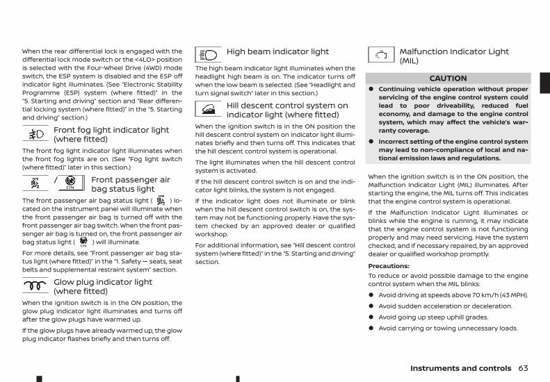
When the rear differential lock is engaged with thedifferential lock mode switch or the <4LO> positionis selected with the Four-Wheel Drive (4WD) modeswitch, the ESP system is disabled and the ESP offindicator light illuminates. (See “Electronic StabilityProgramme (ESP) system (where fitted)” in the“5. Starting and driving” section and “Rear differen-tial locking system (where fitted)” in the “5. Startingand driving” section.)
Front fog light indicator light(where fitted)
The front fog light indicator light illuminates whenthe front fog lights are on. (See “Fog light switch(where fitted)” later in this section.)
/ Front passenger airbag status light
The front passenger air bag status light ( ) lo-cated on the instrument panel will illuminate whenthe front passenger air bag is turned off with thefront passenger air bag switch. When the front pas-senger air bag is turned on, the front passenger airbag status light ( ) will illuminate.
For more details, see “Front passenger air bag sta-tus light (where fitted)” in the “1. Safety — seats, seatbelts and supplemental restraint system” section.
Glow plug indicator light(where fitted)
When the ignition switch is in the ON position, theglow plug indicator light illuminates and turns offafter the glow plugs have warmed up.
If the glow plugs have already warmed up, the glowplug indicator flashes briefly and then turns off.
High beam indicator light
The high beam indicator light illuminates when theheadlight high beam is on. The indicator turns offwhen the low beam is selected. (See “Headlight andturn signal switch” later in this section.)
Hill descent control system onindicator light (where fitted)
When the ignition switch is in the ON position thehill descent control system on indicator light illumi-nates briefly and then turns off. This indicates thatthe hill descent control system is operational.
The light illuminates when the hill descent controlsystem is activated.
If the hill descent control switch is on and the indi-cator light blinks, the system is not engaged.
If the indicator light does not illuminate or blinkwhen the hill descent control switch is on, the sys-tem may not be functioning properly. Have the sys-tem checked by an approved dealer or qualifiedworkshop.
For additional information, see “Hill descent controlsystem (where fitted)” in the “5. Starting and driving”section.
Malfunction Indicator Light(MIL)
CAUTION• Continuing vehicle operation without proper
servicing of the engine control system couldlead to poor driveability, reduced fueleconomy, and damage to the engine controlsystem, which may affect the vehicle’s war-ranty coverage.
• Incorrect setting of the engine control systemmay lead to non-compliance of local and na-tional emission laws and regulations.
When the ignition switch is in the ON position, theMalfunction Indicator Light (MIL) illuminates. Afterstarting the engine, the MIL turns off. This indicatesthat the engine control system is operational.
If the Malfunction Indicator Light illuminates orblinks while the engine is running, it may indicatethat the engine control system is not functioningproperly and may need servicing. Have the systemchecked, and if necessary repaired, by an approveddealer or qualified workshop promptly.
Precautions:To reduce or avoid possible damage to the enginecontrol system when the MIL blinks:
• Avoid driving at speeds above 70 km/h (43 MPH).
• Avoid sudden acceleration or deceleration.
• Avoid going up steep uphill grades.
• Avoid carrying or towing unnecessary loads.
Instruments and controls 63
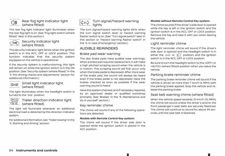
Rear fog light indicator light(where fitted)
The rear fog light indicator light illuminates whenthe rear fog light is on. (See “Fog light switch (wherefitted)” later in this section.)
Security indicator light(where fitted)
The security indicator light blinks when the ignitionswitch is in the ACC, OFF or LOCK position. Thisfunction indicates that the security systemequipped on the vehicle is operational.
If the security system is malfunctioning, this lightwill remain on while the ignition switch is in the ONposition. (See “Security system (where fitted)” in the“3. Pre-driving checks and adjustments” section foradditional information.)
Small light indicator light(where fitted)
The light illuminates when the headlight switch isturned to the position.
Trailer direction indicator light(where fitted)
The light will illuminate whenever an additionalelectrical load is detected by the direction indicatorsystem.
For additional information, see “Trailer towing” in the“5. Starting and driving” section.
Turn signal/hazard warninglights
The turn signal/hazard warning lights blink whenthe turn signal switch lever or hazard warningflasher switch is on. (See “Turn signal switch” later inthis section or “Hazard warning flasher switch” inthe “6. In case of emergency” section.)
AUDIBLE REMINDERSBrake pad wear warningThe disc brake pads have audible wear warnings.When a brake pad requires replacement, it will makea high pitched scraping sound when the vehicle isin motion. This scraping sound will first occur onlywhen the brake pedal is depressed. After more wearof the brake pad, the sound will always be heardeven if the brake pedal is not depressed. Have thebrakes checked as soon as possible if the wearwarning sound is heard.
Have the system checked, and if necessary repaired,by an approved dealer or qualified workshoppromptly. (See “Brakes” in the “8. Maintenance anddo-it-yourself” section.)
Key reminder chimeThe chime will sound if any of the following opera-tions are detected:
Models with Remote Control Key system:The chime will sound if the driver side door isopened while the ignition switch is placed in theACC position.
Models without Remote Control Key system:The chime sounds if the driver's side door is openedwhile the key is left in the ignition switch and theignition switch is in the ACC, OFF or LOCK position.Remove the key and take it with you when leavingthe vehicle.
Light reminder chimeThe light reminder chime will sound if the driver’sside door is opened and the headlight switch is ineither the or position, and the ignitionswitch is in the ACC, OFF or LOCK position.
Be sure to turn the headlight switch to the <OFF> or<AUTO> (where fitted) position when you leave thevehicle.
Parking brake reminder chimeThe parking brake reminder chime will sound if thevehicle is driven at more than 7 km/h (4 MPH) withthe parking brake applied. Stop the vehicle and re-lease the parking brake.
Seat belt warning chime (where fitted)When the vehicle speed exceeds 15 km/h (10 MPH),the chime will sound unless the driver's and/or thefront passenger's seat belts are securely fastened.The chime will continue to sound for about 95 sec-onds until the seat belt is fastened.
64 Instruments and controls
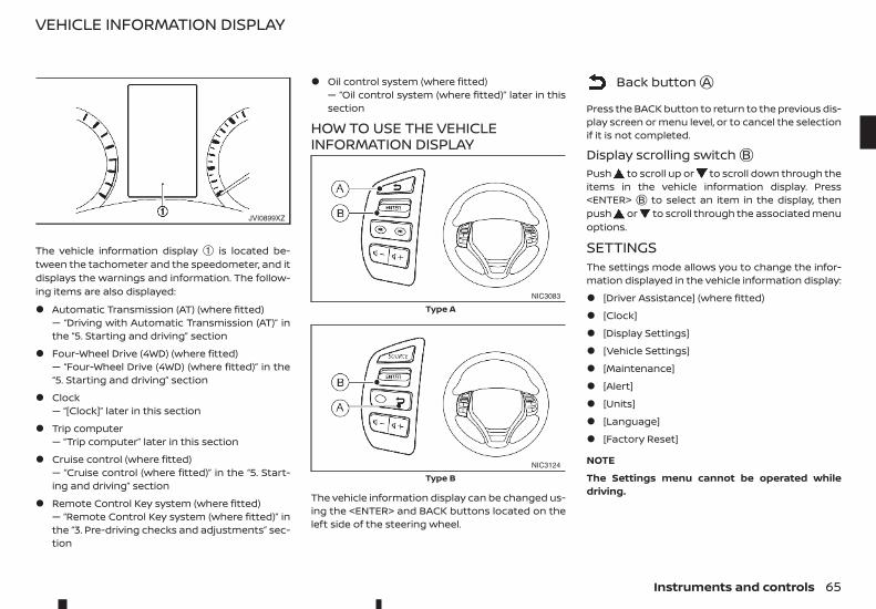
The vehicle information display ➀ is located be-tween the tachometer and the speedometer, and itdisplays the warnings and information. The follow-ing items are also displayed:
• Automatic Transmission (AT) (where fitted)— “Driving with Automatic Transmission (AT)” inthe “5. Starting and driving” section
• Four-Wheel Drive (4WD) (where fitted)— “Four-Wheel Drive (4WD) (where fitted)” in the“5. Starting and driving” section
• Clock— “[Clock]” later in this section
• Trip computer— “Trip computer” later in this section
• Cruise control (where fitted)— “Cruise control (where fitted)” in the “5. Start-ing and driving” section
• Remote Control Key system (where fitted)— “Remote Control Key system (where fitted)” inthe “3. Pre-driving checks and adjustments” sec-tion
• Oil control system (where fitted)— “Oil control system (where fitted)” later in thissection
HOW TO USE THE VEHICLEINFORMATION DISPLAY
The vehicle information display can be changed us-ing the <ENTER> and BACK buttons located on theleft side of the steering wheel.
m Back buttonjA
Press the BACK button to return to the previous dis-play screen or menu level, or to cancel the selectionif it is not completed.
Display scrolling switchjBPush to scroll up or to scroll down through theitems in the vehicle information display. Press<ENTER> jB to select an item in the display, thenpush or to scroll through the associated menuoptions.
SETTINGSThe settings mode allows you to change the infor-mation displayed in the vehicle information display:
• [Driver Assistance] (where fitted)
• [Clock]
• [Display Settings]
• [Vehicle Settings]
• [Maintenance]
• [Alert]
• [Units]
• [Language]
• [Factory Reset]
NOTE
The Settings menu cannot be operated whiledriving.
JVI0899XZ
NIC3083
Type A
NIC3124
Type B
VEHICLE INFORMATION DISPLAY
Instruments and controls 65
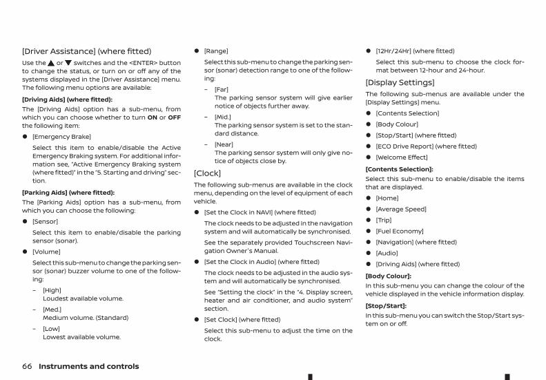
[Driver Assistance] (where fitted)Use the or switches and the <ENTER> buttonto change the status, or turn on or off any of thesystems displayed in the [Driver Assistance] menu.The following menu options are available:
[Driving Aids] (where fitted):The [Driving Aids] option has a sub-menu, fromwhich you can choose whether to turn ON or OFFthe following item:
• [Emergency Brake]
Select this item to enable/disable the ActiveEmergency Braking system. For additional infor-mation see, “Active Emergency Braking system(where fitted)” in the “5. Starting and driving” sec-tion.
[Parking Aids] (where fitted):The [Parking Aids] option has a sub-menu, fromwhich you can choose the following:
• [Sensor]
Select this item to enable/disable the parkingsensor (sonar).
• [Volume]
Select this sub-menu to change the parking sen-sor (sonar) buzzer volume to one of the follow-ing:
– [High]Loudest available volume.
– [Med.]Medium volume. (Standard)
– [Low]Lowest available volume.
• [Range]
Select this sub-menu to change the parking sen-sor (sonar) detection range to one of the follow-ing:
– [Far]The parking sensor system will give earliernotice of objects further away.
– [Mid.]The parking sensor system is set to the stan-dard distance.
– [Near]The parking sensor system will only give no-tice of objects close by.
[Clock]The following sub-menus are available in the clockmenu, depending on the level of equipment of eachvehicle.
• [Set the Clock in NAVI] (where fitted)
The clock needs to be adjusted in the navigationsystem and will automatically be synchronised.
See the separately provided Touchscreen Navi-gation Owner's Manual.
• [Set the Clock in Audio] (where fitted)
The clock needs to be adjusted in the audio sys-tem and will automatically be synchronised.
See “Setting the clock” in the “4. Display screen,heater and air conditioner, and audio system”section.
• [Set Clock] (where fitted)
Select this sub-menu to adjust the time on theclock.
• [12Hr/24Hr] (where fitted)
Select this sub-menu to choose the clock for-mat between 12-hour and 24-hour.
[Display Settings]The following sub-menus are available under the[Display Settings] menu.
• [Contents Selection]
• [Body Colour]
• [Stop/Start] (where fitted)
• [ECO Drive Report] (where fitted)
• [Welcome Effect]
[Contents Selection]:Select this sub-menu to enable/disable the itemsthat are displayed.
• [Home]
• [Average Speed]
• [Trip]
• [Fuel Economy]
• [Navigation] (where fitted)
• [Audio]
• [Driving Aids] (where fitted)
[Body Colour]:In this sub-menu you can change the colour of thevehicle displayed in the vehicle information display.
[Stop/Start]:In this sub-menu you can switch the Stop/Start sys-tem on or off.
66 Instruments and controls
[ECO Drive Report] (where fitted):There are 2 items in the [ECO Drive Report] menu.
• [Display]
Select this item to enable/disable the ECO DriveReport in the vehicle information display.
• [View History]
Select this sub-menu to show the fuel economyhistory, current economy, and the best fueleconomy. See, “ECO drive report” in the “5. Start-ing and driving” section.
– [Back] will return you to the [ECO Drive Re-port] menu.
– [Reset] will reset the fuel economy history tozero.
[Welcome Effect]:Select this sub-menu to enable/disable the itemsdescribed below to ON or OFF.
• [Dial and Pointer]
The indicator needles sweep in the meters whenthe engine is started.
• [Display Effect]
The welcome screen display appears when theignition is placed in the ON position.
[Vehicle Settings]The following sub-menus are available under the[Vehicle Settings] menu.
• [Lighting]
• [Turn Indicator]
• [Unlocking]
• [Wipers]
[Lighting] (where fitted):There are 2 items under the Lighting menu.
• [Int. Lamp Timer]
Select this item to enable/disable the interiorlamp timer feature.
The interior lights will be ON if any door is un-locked when the interior lamp timer is enabled.
• [Auto Lights]
The automatic lighting system can be set to illu-minate earlier or later based on the brightnessoutside the vehicle. See, “Headlight and turn sig-nal switch” in the “2. Instruments and controls”section.
– [On Earliest]
– [On Earlier]
– [Standard]
– [On Later]
[Turn Indicator]:Select this sub-menu to enable/disable the itemsdescribed below to ON or OFF.
• [3 Flash On]
Select this sub-menu to enable/disable the [3Flash On] lane change signal feature. See, “Turnsignal switch” in the “2. Instruments andcontrols” section.
[Unlocking] (where fitted):Select this sub-menu to enable/disable the itemsdescribed below to ON or OFF.
• [I-Key Door Lock]
Select this item to activate/deactivate the re-quest switch on the door. See, “Doors” in the“3. Pre-driving checks and adjustments” section.
[Wipers]:Select this sub-menu to enable/disable the itemsdescribed below to ON or OFF.
• [Speed Dependent]
Select this item to activate/deactivate the speeddependent wiper speed feature. See, “Wiper andwasher switch” in the “2. Instruments andcontrols” section.
Instruments and controls 67
[Maintenance]The following sub-menus are available under the[Maintenance] menu.
• [Service]
• [Filter]
• [Tyre]
• [Other]
• [AdBlue Status]
[Service] (where fitted):Select this item to show the remaining distance un-til servicing is required.
To reset the service indicator, push <ENTER> andselect [Yes].
The distance to service interval cannot be adjustedmanually. The interval is set automatically.
NOTE
Be sure the distance to service indicator is resetafter servicing. Otherwise, the service indicatorwill continue to be displayed.
[Filter] (where fitted):Select this item to set or reset the distance for re-placing the oil filter.
The distance can be set from [ — — — ] (off) to 30.000km in 500 km increments.
[Tyre]:Select this item to set or reset the distance for re-placing the tyres.
The distance can be set from [ — — — ] (off) to 30.000km in 500 km increments.
[Other]:Select this item to set or reset a reminder for replac-ing something other than service, the oil filter, ortyres.
The distance can be set from [ — — — ] (off) to 30.000km in 500 km increments.
[AdBlue Status]:You can use this option to check the level of fluid inthe AdBlue® tank.
For more details see “AdBlue® Selective CatalyticReduction (SCR) system” in the “5. Starting anddriving” section
[Alert]The following items are available under the [Alert]menu.
• [Timer]
• [Navigation] (where fitted)
• [Phone] (where fitted)
• [Mail] (where fitted)
[Timer]:Select this sub-menu to specify when the [Time fora driver break?] message activates.
The time can be set from [ — — — ] (off) to 6 hours inincrements of 30 minutes.
[Navigation] (where fitted):Select this item to enable/disable the navigationsystem information in the vehicle information dis-play.
[Phone] (where fitted):Select this item to enable/disable incoming call in-formation in the vehicle information display.
[Mail] (where fitted):Select this item to enable/disable incoming mail in-formation in the vehicle information display.
[Units]The following items are available under the [Units]menu.
• [Distance/Fuel]
• [Temperature]
[Distance/Fuel]:The unit for the distance and fuel consumption thatdisplays in the vehicle information display can bechanged to:
• [km, l/100km]
• [km, km/l]
• [miles, MPG]
[Temperature]:The temperature that displays in the vehicle infor-mation display can be changed from:
• °C (Celsius)
• °F (Fahrenheit)
[Language]The language of the vehicle information display canbe changed to:
• English
• French
• German
68 Instruments and controls
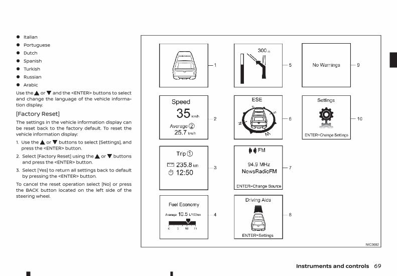
• Italian
• Portuguese
• Dutch
• Spanish
• Turkish
• Russian
• Arabic
Use the or and the <ENTER> buttons to selectand change the language of the vehicle informa-tion display.
[Factory Reset]The settings in the vehicle information display canbe reset back to the factory default. To reset thevehicle information display:
1. Use the or buttons to select [Settings], andpress the <ENTER> button.
2. Select [Factory Reset] using the or buttonsand press the <ENTER> button.
3. Select [Yes] to return all settings back to defaultby pressing the <ENTER> button.
To cancel the reset operation select [No] or pressthe BACK button located on the left side of thesteering wheel.
NIC3682
Instruments and controls 69
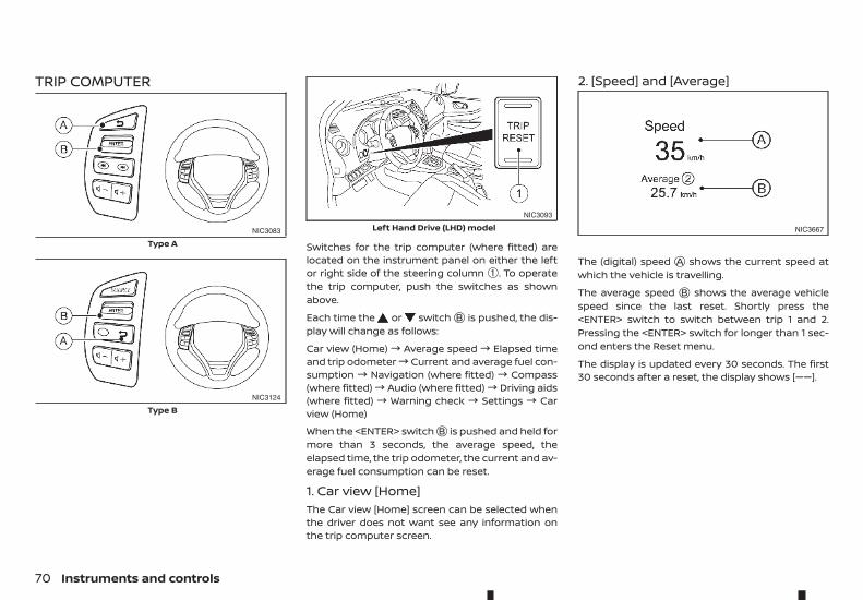
TRIP COMPUTER
Switches for the trip computer (where fitted) arelocated on the instrument panel on either the leftor right side of the steering column ➀. To operatethe trip computer, push the switches as shownabove.
Each time the or switchjB is pushed, the dis-play will change as follows:
Car view (Home)! Average speed! Elapsed timeand trip odometer! Current and average fuel con-sumption ! Navigation (where fitted) ! Compass(where fitted)! Audio (where fitted)! Driving aids(where fitted) ! Warning check ! Settings ! Carview (Home)
When the <ENTER> switchjB is pushed and held formore than 3 seconds, the average speed, theelapsed time, the trip odometer, the current and av-erage fuel consumption can be reset.
1. Car view [Home]The Car view [Home] screen can be selected whenthe driver does not want see any information onthe trip computer screen.
2. [Speed] and [Average]
The (digital) speed jA shows the current speed atwhich the vehicle is travelling.
The average speed jB shows the average vehiclespeed since the last reset. Shortly press the<ENTER> switch to switch between trip 1 and 2.Pressing the <ENTER> switch for longer than 1 sec-ond enters the Reset menu.
The display is updated every 30 seconds. The first30 seconds after a reset, the display shows [——].
NIC3083
Type A
NIC3124
Type B
NIC3093
Left Hand Drive (LHD) model NIC3667
70 Instruments and controls
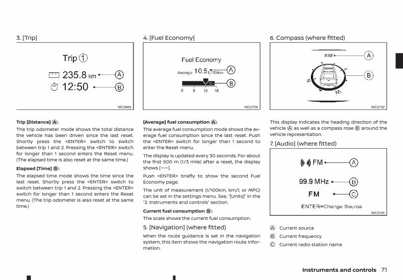
3. [Trip]
Trip [Distance]jA :The trip odometer mode shows the total distancethe vehicle has been driven since the last reset.Shortly press the <ENTER> switch to switchbetween trip 1 and 2. Pressing the <ENTER> switchfor longer than 1 second enters the Reset menu.(The elapsed time is also reset at the same time.)
Elapsed [Time]jB :The elapsed time mode shows the time since thelast reset. Shortly press the <ENTER> switch toswitch between trip 1 and 2. Pressing the <ENTER>switch for longer than 1 second enters the Resetmenu. (The trip odometer is also reset at the sametime.)
4. [Fuel Economy]
[Average] fuel consumptionjA :The average fuel consumption mode shows the av-erage fuel consumption since the last reset. Pushthe <ENTER> switch for longer than 1 second toenter the Reset menu.
The display is updated every 30 seconds. For aboutthe first 500 m (1/3 mile) after a reset, the displayshows [——].
Push <ENTER> briefly to show the second FuelEconomy page.
The unit of measurement (l/100km, km/l, or MPG)can be set in the settings menu. See, “[Units]” in the“2. Instruments and controls” section.
Current fuel consumptionjB :The scale shows the current fuel consumption.
5. [Navigation] (where fitted)When the route guidance is set in the navigationsystem, this item shows the navigation route infor-mation.
6. Compass (where fitted)
This display indicates the heading direction of thevehiclejA as well as a compass rosejB around thevehicle representation.
7. [Audio] (where fitted)
jA Current sourcejB Current frequencyjC Current radio station name
NIC3666 NIC2758 NIC2732
NIC3105
Instruments and controls 71
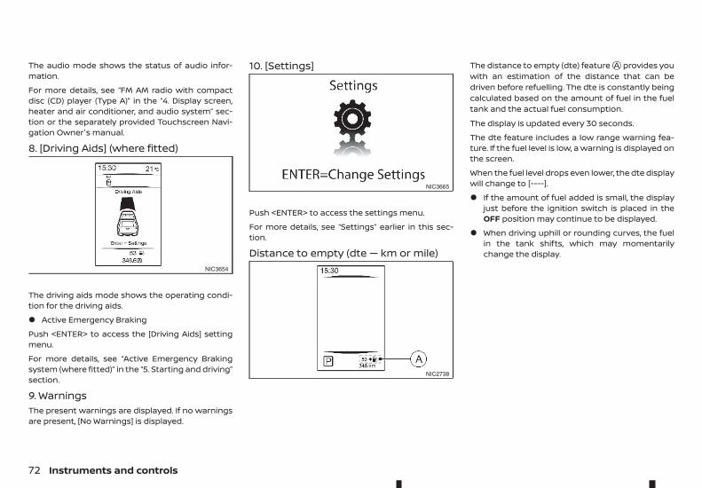
The audio mode shows the status of audio infor-mation.
For more details, see “FM AM radio with compactdisc (CD) player (Type A)” in the “4. Display screen,heater and air conditioner, and audio system” sec-tion or the separately provided Touchscreen Navi-gation Owner's manual.
8. [Driving Aids] (where fitted)
The driving aids mode shows the operating condi-tion for the driving aids.
• Active Emergency Braking
Push <ENTER> to access the [Driving Aids] settingmenu.
For more details, see “Active Emergency Brakingsystem (where fitted)” in the “5. Starting and driving”section.
9. WarningsThe present warnings are displayed. If no warningsare present, [No Warnings] is displayed.
10. [Settings]
Push <ENTER> to access the settings menu.
For more details, see “Settings” earlier in this sec-tion.
Distance to empty (dte — km or mile)
The distance to empty (dte) featurejA provides youwith an estimation of the distance that can bedriven before refuelling. The dte is constantly beingcalculated based on the amount of fuel in the fueltank and the actual fuel consumption.
The display is updated every 30 seconds.
The dte feature includes a low range warning fea-ture. If the fuel level is low, a warning is displayed onthe screen.
When the fuel level drops even lower, the dte displaywill change to [----].
• If the amount of fuel added is small, the displayjust before the ignition switch is placed in theOFF position may continue to be displayed.
• When driving uphill or rounding curves, the fuelin the tank shifts, which may momentarilychange the display.
NIC3654
NIC3665
NIC2738
72 Instruments and controls
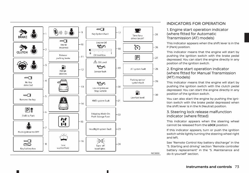
INDICATORS FOR OPERATION1. Engine start operation indicator(where fitted for AutomaticTransmission (AT) models)This indicator appears when the shift lever is in theP (Park) position.
This indicator means that the engine will start bypushing the ignition switch with the brake pedaldepressed. You can start the engine directly in anyposition of the ignition switch.
2. Engine start operation indicator(where fitted for Manual Transmission(MT) models)This indicator means that the engine will start bypushing the ignition switch with the clutch pedaldepressed. You can start the engine directly in anyposition of the ignition switch.
You can also start the engine by pushing the igni-tion switch with the brake pedal depressed whenthe shift lever is in the N (Neutral) position.
3. Steering lock release malfunctionindicator (where fitted)This indicator appears when the steering wheelcannot be released from the LOCK position.
If this indicator appears, turn or push the ignitionswitch while lightly turning the steering wheel rightand left.
See “Remote Control Key battery discharge” in the“5. Starting and driving” section “Remote controllerbattery replacement” in the “5. Maintenance anddo-it-yourself” section.NIC3659
Instruments and controls 73
4. No Key Detected warning(where fitted)This warning appears when the door is closed withthe Remote Control Key left outside the vehicle andthe ignition switch in the ON position. Make surethat the Remote Control Key is inside the vehicle.
See “Remote Control Key system (where fitted)” inthe “3. Pre-driving checks and adjustments” sectionfor more details.
5. Key reminder warning (where fitted)This warning appears if the driver's side door isopened while the key is left in the ignition switchand ignition switch is in the ACC, OFF or LOCK posi-tion. Remove the key and take it with you when leav-ing the vehicle.
6. Shift to Park warning (where fittedfor AT models)This warning appears when the ignition switch ispushed to stop the engine with the shift lever in anyposition except the P (Park) position.
If this warning appears, move the shift lever to theP (Park) position or push the ignition switch to theON position.
An inside warning chime will also sound. (See“Shifting” in the “5. Starting and driving” section.)
7. Push ignition to OFF warning (wherefitted for AT models)This warning appears when the shift lever is movedto the P (Park) position with the ignition switch inthe ACC position after the Shift to Park warning ap-pears.
To push the ignition switch to the OFF position, per-form the following procedure:
Shift to Park warning! (Move the shift lever to P)! PUSH warning ! (Push the ignition switch !ignition switch position is turned to ON) ! PUSHwarning ! (Push the ignition switch ! ignitionswitch position is turned to OFF)
8. Key Battery low warning(where fitted)This warning appears when the Remote Control Keybattery is running out of power.
If this warning appears, replace the battery with anew one. (See “Remote controller/Intelligent Keybattery (where fitted)” in the “8. Maintenance anddo-it-yourself” section.)
9. Engine start operation for RemoteControl Key system indicator (wherefitted)This indicator appears when the Remote ControlKey battery is running out of power and when theRemote Control Key system and vehicle are notcommunicating normally.
If this indicator appears, touch the ignition switchwith the Remote Control Key while depressing thebrake pedal. (See “Remote Control Key batterydischarge” in the “5. Starting and driving” section.)
10. Key ID Incorrect warning(where fitted)This warning appears when the ignition switch ischanged from the LOCK position and the RemoteControl Key cannot be recognised by the system.
You cannot start the engine with an unregisteredkey. Use the registered Remote Control Key.
See “Remote Control Key system (where fitted)” inthe “3. Pre-driving checks and adjustments” section.
11. Release Parking Brake warningThis warning appears when the vehicle speed isabove 7 km/h (4 MPH) and the parking brake is ap-plied. Stop the vehicle and release the parking brake.
12. Low fuel warningThis warning appears when the fuel level in the tankis getting low. Refuel as soon as it is convenient,preferably before the fuel gauge reaches the empty(0) position.
There will be a small reserve of fuel remaining inthe tank when the fuel gauge reaches the empty(0) position.
13. Door open warningThis warning appears if any of the doors are openor not closed securely. The vehicle icon indicateswhich door is open on the display. Make sure that allof the doors are closed.
14. Second row seat belt warning(where fitted)This second row seat belt warning appears afterthe ignition switch is placed in the ON position. Ifany of the second row seat passenger seat belts isnot fastened, a chime will sound and the seat iconilluminates in red to show which seat belt is not fas-tened. The seat icon illuminates in red until the cor-responding second row seat passenger’s seat beltis fastened. The warning will automatically turn offafter approximately 35 seconds.
74 Instruments and controls
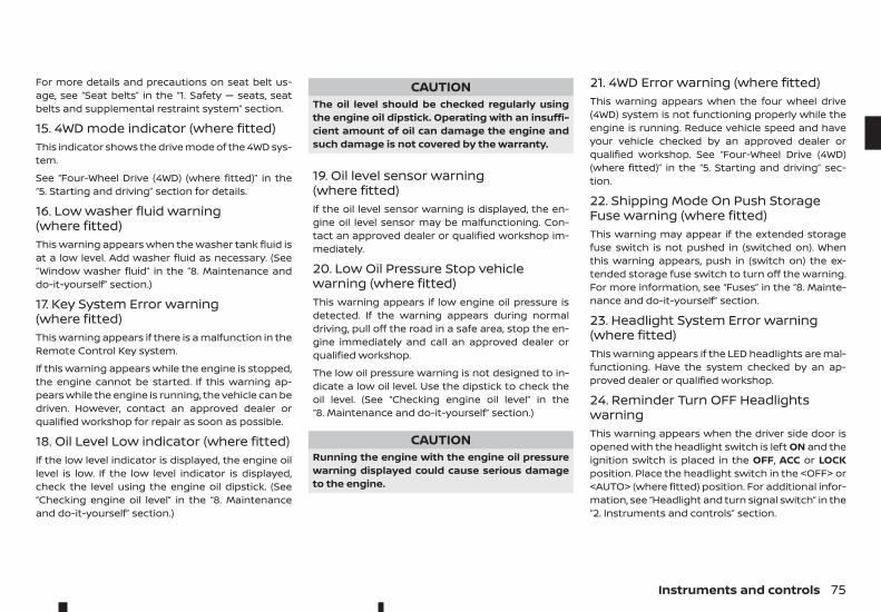
For more details and precautions on seat belt us-age, see “Seat belts” in the “1. Safety — seats, seatbelts and supplemental restraint system” section.
15. 4WD mode indicator (where fitted)This indicator shows the drive mode of the 4WD sys-tem.
See “Four-Wheel Drive (4WD) (where fitted)” in the“5. Starting and driving” section for details.
16. Low washer fluid warning(where fitted)This warning appears when the washer tank fluid isat a low level. Add washer fluid as necessary. (See“Window washer fluid” in the “8. Maintenance anddo-it-yourself” section.)
17. Key System Error warning(where fitted)This warning appears if there is a malfunction in theRemote Control Key system.
If this warning appears while the engine is stopped,the engine cannot be started. If this warning ap-pears while the engine is running, the vehicle can bedriven. However, contact an approved dealer orqualified workshop for repair as soon as possible.
18. Oil Level Low indicator (where fitted)If the low level indicator is displayed, the engine oillevel is low. If the low level indicator is displayed,check the level using the engine oil dipstick. (See“Checking engine oil level” in the “8. Maintenanceand do-it-yourself” section.)
CAUTIONThe oil level should be checked regularly usingthe engine oil dipstick. Operating with an insuffi-cient amount of oil can damage the engine andsuch damage is not covered by the warranty.
19. Oil level sensor warning(where fitted)If the oil level sensor warning is displayed, the en-gine oil level sensor may be malfunctioning. Con-tact an approved dealer or qualified workshop im-mediately.
20. Low Oil Pressure Stop vehiclewarning (where fitted)This warning appears if low engine oil pressure isdetected. If the warning appears during normaldriving, pull off the road in a safe area, stop the en-gine immediately and call an approved dealer orqualified workshop.
The low oil pressure warning is not designed to in-dicate a low oil level. Use the dipstick to check theoil level. (See “Checking engine oil level” in the“8. Maintenance and do-it-yourself” section.)
CAUTIONRunning the engine with the engine oil pressurewarning displayed could cause serious damageto the engine.
21. 4WD Error warning (where fitted)This warning appears when the four wheel drive(4WD) system is not functioning properly while theengine is running. Reduce vehicle speed and haveyour vehicle checked by an approved dealer orqualified workshop. See “Four-Wheel Drive (4WD)(where fitted)” in the “5. Starting and driving” sec-tion.
22. Shipping Mode On Push StorageFuse warning (where fitted)This warning may appear if the extended storagefuse switch is not pushed in (switched on). Whenthis warning appears, push in (switch on) the ex-tended storage fuse switch to turn off the warning.For more information, see “Fuses” in the “8. Mainte-nance and do-it-yourself” section.
23. Headlight System Error warning(where fitted)This warning appears if the LED headlights are mal-functioning. Have the system checked by an ap-proved dealer or qualified workshop.
24. Reminder Turn OFF HeadlightswarningThis warning appears when the driver side door isopened with the headlight switch is left ON and theignition switch is placed in the OFF, ACC or LOCKposition. Place the headlight switch in the <OFF> or<AUTO> (where fitted) position. For additional infor-mation, see “Headlight and turn signal switch” in the“2. Instruments and controls” section.
Instruments and controls 75
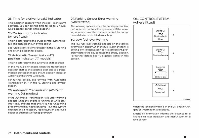
25. Time for a driver break? indicatorThis indicator appears when the set [Timer] alarmactivates. You can set the time for up to 6 hours.(See “Settings” earlier in this section.)
26. Cruise control indicator(where fitted)This indicator shows the cruise control system sta-tus. The status is shown by the colour.
See “Cruise control (where fitted)” in the “5. Startingand driving” section for details.
27. Automatic Transmission (AT)position indicator (AT models)This indicator shows the automatic shift position.
In the manual shift mode, when the transmissiondoes not shift to the selected gear due to a trans-mission protection mode, the AT position indicatorwill blink and a chime will sound.
For further details, see “Driving with AutomaticTransmission (AT)” in the “5. Starting and driving”section.
28. Automatic Transmission (AT) Errorwarning (AT models)If the Automatic Transmission (AT) Error warningappears while the engine is running, or while driv-ing, it may indicate that the AT is not functioningproperly and may need servicing. Have the systemchecked, and if necessary repaired, by an approveddealer or qualified workshop promptly.
29. Parking Sensor Error warning(where fitted)This warning appears when the parking sensor (so-nar) system is not functioning properly. If the warn-ing appears, have the system checked by an ap-proved dealer or qualified workshop.
30. Low fuel level warningThe low fuel level warning appears on the vehicleinformation display when the fuel level in the tank isgetting low. Refuel as soon as it is convenient, pref-erably before the gauge reads the empty position.For further details, see “Fuel gauge” earlier in thissection.
OIL CONTROL SYSTEM(where fitted)
When the ignition switch is in the ON position, en-gine oil information is displayed.
Engine oil information informs the distance to oilchange, oil level indication and malfunction of oillevel sensor.
JVI1244X
76 Instruments and controls
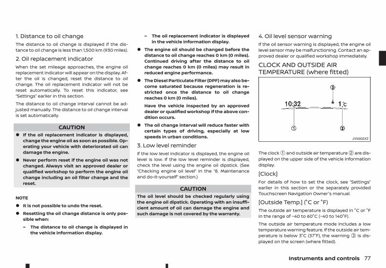
1. Distance to oil changeThe distance to oil change is displayed if the dis-tance to oil change is less than 1,500 km (930 miles).
2. Oil replacement indicatorWhen the set mileage approaches, the engine oilreplacement indicator will appear on the display. Af-ter the oil is changed, reset the distance to oilchange. The oil replacement indicator will not bereset automatically. To reset this indicator, see“Settings” earlier in this section.
The distance to oil change interval cannot be ad-justed manually. The distance to oil change intervalis set automatically.
CAUTION• If the oil replacement indicator is displayed,
change the engine oil as soon as possible. Op-erating your vehicle with deteriorated oil candamage the engine.
• Never perform reset if the engine oil was notchanged. Always visit an approved dealer orqualified workshop to perform the engine oilchange including an oil filter change and thereset.
NOTE
• It is not possible to undo the reset.
• Resetting the oil change distance is only pos-sible when:
– The distance to oil change is displayed inthe vehicle information display.
– The oil replacement indicator is displayedin the vehicle information display.
• The engine oil should be changed before thedistance to oil change reaches 0 km (0 miles).Continued driving after the distance to oilchange reaches 0 km (0 miles) may result inreduced engine performance.
• The Diesel Particulate Filter (DPF) may also be-come saturated because regeneration is re-stricted once the distance to oil changereaches 0 km (0 miles).
Have the vehicle inspected by an approveddealer or qualified workshop if the above con-dition occurs.
• The oil change interval will reduce faster withcertain types of driving, especially at lowspeeds in urban conditions.
3. Low level reminderIf the low level indicator is displayed, the engine oillevel is low. If the low level reminder is displayed,check the level using the engine oil dipstick. (See“Checking engine oil level” in the “8. Maintenanceand do-it-yourself” section.)
CAUTIONThe oil level should be checked regularly usingthe engine oil dipstick. Operating with an insuffi-cient amount of oil can damage the engine andsuch damage is not covered by the warranty.
4. Oil level sensor warningIf the oil sensor warning is displayed, the engine oillevel sensor may be malfunctioning. Contact an ap-proved dealer or qualified workshop immediately.
CLOCK AND OUTSIDE AIRTEMPERATURE (where fitted)
The clock ➀ and outside air temperature ➁ are dis-played on the upper side of the vehicle informationdisplay.
[Clock]For details of how to set the clock, see “Settings”earlier in this section or the separately providedTouchscreen Navigation Owner's manual.
[Outside Temp.] (°C or °F)The outside air temperature is displayed in °C or °Fin the range of −40 to 60°C (−40 to 140°F).
The outside air temperature mode includes a lowtemperature warning feature. If the outside air tem-perature is below 3°C (37°F), the warning ➂ is dis-played on the screen (where fitted).
JVI0932XZ
Instruments and controls 77
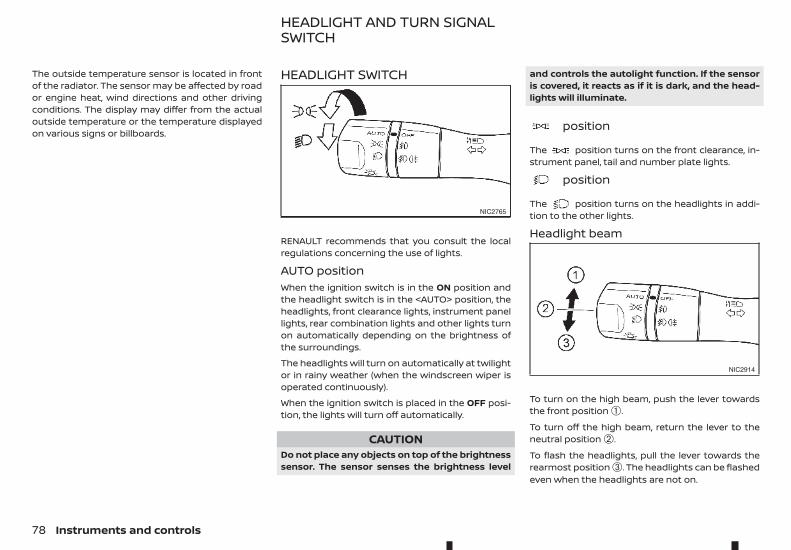
The outside temperature sensor is located in frontof the radiator. The sensor may be affected by roador engine heat, wind directions and other drivingconditions. The display may differ from the actualoutside temperature or the temperature displayedon various signs or billboards.
HEADLIGHT SWITCH
RENAULT recommends that you consult the localregulations concerning the use of lights.
AUTO positionWhen the ignition switch is in the ON position andthe headlight switch is in the <AUTO> position, theheadlights, front clearance lights, instrument panellights, rear combination lights and other lights turnon automatically depending on the brightness ofthe surroundings.
The headlights will turn on automatically at twilightor in rainy weather (when the windscreen wiper isoperated continuously).
When the ignition switch is placed in the OFF posi-tion, the lights will turn off automatically.
CAUTIONDo not place any objects on top of the brightnesssensor. The sensor senses the brightness level
and controls the autolight function. If the sensoris covered, it reacts as if it is dark, and the head-lights will illuminate.
m position
The position turns on the front clearance, in-strument panel, tail and number plate lights.
m position
The position turns on the headlights in addi-tion to the other lights.
Headlight beam
To turn on the high beam, push the lever towardsthe front position ➀.
To turn off the high beam, return the lever to theneutral position ➁.
To flash the headlights, pull the lever towards therearmost position ➂. The headlights can be flashedeven when the headlights are not on.
NIC2765
NIC2914
HEADLIGHT AND TURN SIGNALSWITCH
78 Instruments and controls
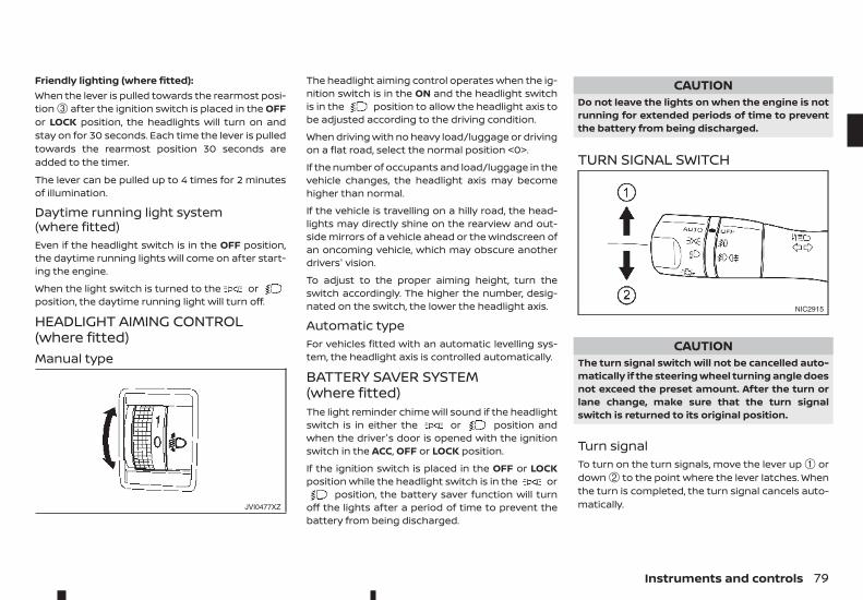
Friendly lighting (where fitted):When the lever is pulled towards the rearmost posi-tion ➂ after the ignition switch is placed in the OFFor LOCK position, the headlights will turn on andstay on for 30 seconds. Each time the lever is pulledtowards the rearmost position 30 seconds areadded to the timer.
The lever can be pulled up to 4 times for 2 minutesof illumination.
Daytime running light system(where fitted)Even if the headlight switch is in the OFF position,the daytime running lights will come on after start-ing the engine.
When the light switch is turned to the orposition, the daytime running light will turn off.
HEADLIGHT AIMING CONTROL(where fitted)Manual type
The headlight aiming control operates when the ig-nition switch is in the ON and the headlight switchis in the position to allow the headlight axis tobe adjusted according to the driving condition.
When driving with no heavy load/luggage or drivingon a flat road, select the normal position <0>.
If the number of occupants and load/luggage in thevehicle changes, the headlight axis may becomehigher than normal.
If the vehicle is travelling on a hilly road, the head-lights may directly shine on the rearview and out-side mirrors of a vehicle ahead or the windscreen ofan oncoming vehicle, which may obscure anotherdrivers' vision.
To adjust to the proper aiming height, turn theswitch accordingly. The higher the number, desig-nated on the switch, the lower the headlight axis.
Automatic typeFor vehicles fitted with an automatic levelling sys-tem, the headlight axis is controlled automatically.
BATTERY SAVER SYSTEM(where fitted)The light reminder chime will sound if the headlightswitch is in either the or position andwhen the driver's door is opened with the ignitionswitch in the ACC, OFF or LOCK position.
If the ignition switch is placed in the OFF or LOCKposition while the headlight switch is in the or
position, the battery saver function will turnoff the lights after a period of time to prevent thebattery from being discharged.
CAUTIONDo not leave the lights on when the engine is notrunning for extended periods of time to preventthe battery from being discharged.
TURN SIGNAL SWITCH
CAUTIONThe turn signal switch will not be cancelled auto-matically if the steering wheel turning angle doesnot exceed the preset amount. After the turn orlane change, make sure that the turn signalswitch is returned to its original position.
Turn signalTo turn on the turn signals, move the lever up ➀ ordown ➁ to the point where the lever latches. Whenthe turn is completed, the turn signal cancels auto-matically.JVI0477XZ
NIC2915
Instruments and controls 79
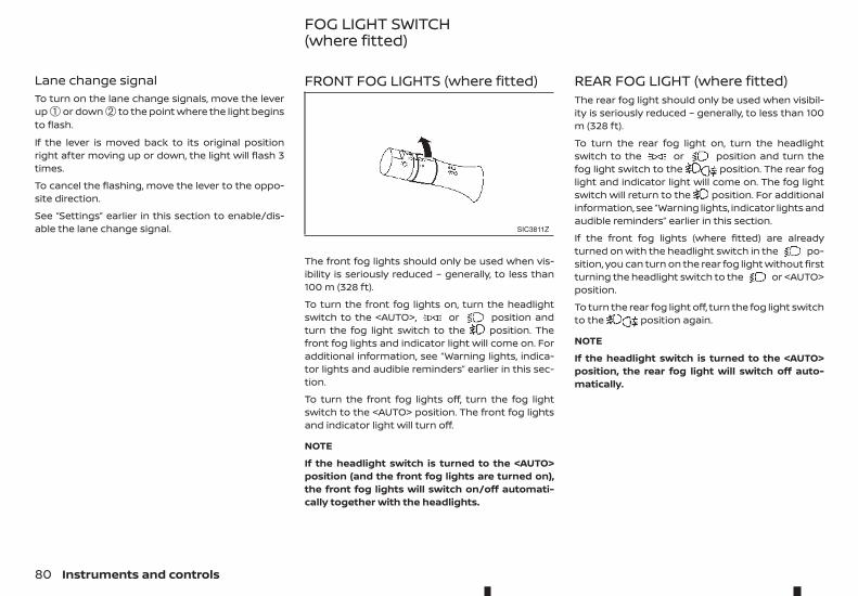
Lane change signalTo turn on the lane change signals, move the leverup ➀ or down ➁ to the point where the light beginsto flash.
If the lever is moved back to its original positionright after moving up or down, the light will flash 3times.
To cancel the flashing, move the lever to the oppo-site direction.
See “Settings” earlier in this section to enable/dis-able the lane change signal.
FRONT FOG LIGHTS (where fitted)
The front fog lights should only be used when vis-ibility is seriously reduced – generally, to less than100 m (328 ft).
To turn the front fog lights on, turn the headlightswitch to the <AUTO>, or position andturn the fog light switch to the position. Thefront fog lights and indicator light will come on. Foradditional information, see “Warning lights, indica-tor lights and audible reminders” earlier in this sec-tion.
To turn the front fog lights off, turn the fog lightswitch to the <AUTO> position. The front fog lightsand indicator light will turn off.
NOTE
If the headlight switch is turned to the <AUTO>position (and the front fog lights are turned on),the front fog lights will switch on/off automati-cally together with the headlights.
REAR FOG LIGHT (where fitted)The rear fog light should only be used when visibil-ity is seriously reduced – generally, to less than 100m (328 ft).
To turn the rear fog light on, turn the headlightswitch to the or position and turn thefog light switch to the position. The rear foglight and indicator light will come on. The fog lightswitch will return to the position. For additionalinformation, see “Warning lights, indicator lights andaudible reminders” earlier in this section.
If the front fog lights (where fitted) are alreadyturned on with the headlight switch in the po-sition, you can turn on the rear fog light without firstturning the headlight switch to the or <AUTO>position.
To turn the rear fog light off, turn the fog light switchto the position again.
NOTE
If the headlight switch is turned to the <AUTO>position, the rear fog light will switch off auto-matically.
SIC3811Z
FOG LIGHT SWITCH(where fitted)
80 Instruments and controls
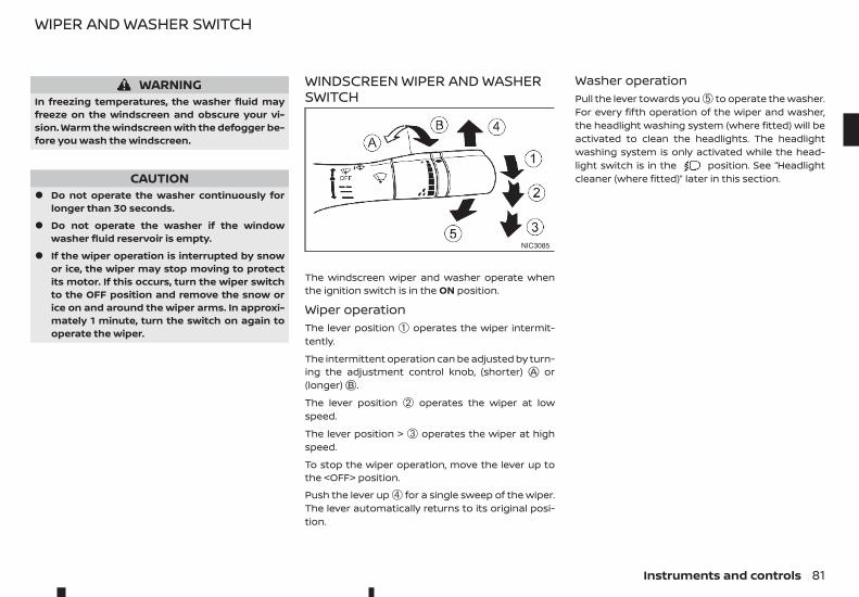
WARNINGIn freezing temperatures, the washer fluid mayfreeze on the windscreen and obscure your vi-sion. Warm the windscreen with the defogger be-fore you wash the windscreen.
CAUTION• Do not operate the washer continuously for
longer than 30 seconds.
• Do not operate the washer if the windowwasher fluid reservoir is empty.
• If the wiper operation is interrupted by snowor ice, the wiper may stop moving to protectits motor. If this occurs, turn the wiper switchto the OFF position and remove the snow orice on and around the wiper arms. In approxi-mately 1 minute, turn the switch on again tooperate the wiper.
WINDSCREEN WIPER AND WASHERSWITCH
The windscreen wiper and washer operate whenthe ignition switch is in the ON position.
Wiper operationThe lever position ➀ operates the wiper intermit-tently.
The intermittent operation can be adjusted by turn-ing the adjustment control knob, (shorter) jA or(longer)jB .
The lever position ➁ operates the wiper at lowspeed.
The lever position > ➂ operates the wiper at highspeed.
To stop the wiper operation, move the lever up tothe <OFF> position.
Push the lever up ➃ for a single sweep of the wiper.The lever automatically returns to its original posi-tion.
Washer operationPull the lever towards you ➄ to operate the washer.For every fifth operation of the wiper and washer,the headlight washing system (where fitted) will beactivated to clean the headlights. The headlightwashing system is only activated while the head-light switch is in the position. See “Headlightcleaner (where fitted)” later in this section.
NIC3085
WIPER AND WASHER SWITCH
Instruments and controls 81
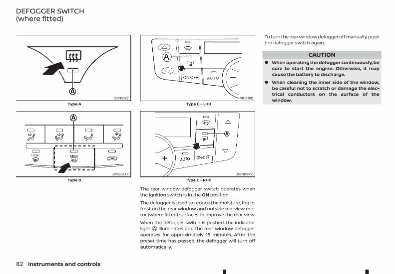
The rear window defogger switch operates whenthe ignition switch is in the ON position.
The defogger is used to reduce the moisture, fog orfrost on the rear window and outside rearview mir-ror (where fitted) surfaces to improve the rear view.
When the defogger switch is pushed, the indicatorlightjA illuminates and the rear window defoggeroperates for approximately 15 minutes. After thepreset time has passed, the defogger will turn offautomatically.
To turn the rear window defogger off manually, pushthe defogger switch again.
CAUTION• When operating the defogger continuously, be
sure to start the engine. Otherwise, it maycause the battery to discharge.
• When cleaning the inner side of the window,be careful not to scratch or damage the elec-trical conductors on the surface of thewindow.SIC3537Z
Type A
JVI0853XZ
Type B
NIC3102
Type C - LHD
JVI1022XZ
Type C - RHD
DEFOGGER SWITCH(where fitted)
82 Instruments and controls
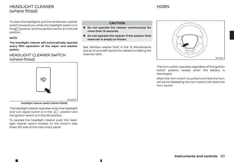
To clean the headlights, pull the windscreen washerswitch towards you while the headlight switch is inthe position and the ignition switch is in the ONposition.
NOTE
The headlight cleaner will automatically operateevery fifth operation of the wiper and washerswitch.
HEADLIGHT CLEANER SWITCH(where fitted)
The headlight cleaner operates when the headlightand turn signal switch is in the position andthe ignition switch is in the ON position.
To operate the headlight cleaner push the head-light cleaner switch located on the driver's side,lower left side of the instrument panel.
CAUTION• Do not operate the cleaner continuously for
more than 15 seconds.
• Do not operate the cleaner if the washer fluidreservoir is empty or frozen.
See “Window washer fluid” in the “8. Maintenanceand do-it-yourself” section for details on refilling thereservoir tank.
The horn switch operates regardless of the ignitionswitch position except when the battery isdischarged.
When the horn switch is pushed and held, the hornwill sound. Releasing the horn switch will cease thehorn sound.
SIC2255Z
Headlight cleaner switch (where fitted)
NIC3084
HEADLIGHT CLEANER(where fitted)
HORN
Instruments and controls 83
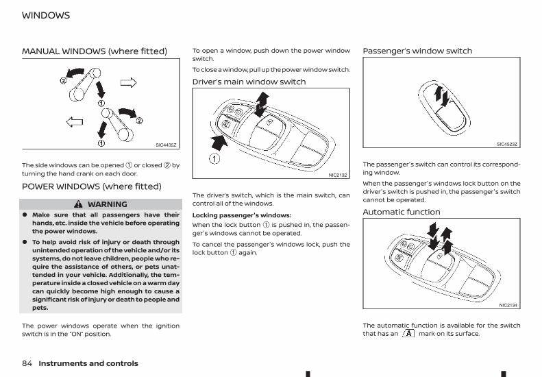
MANUAL WINDOWS (where fitted)
The side windows can be opened ➀ or closed ➁ byturning the hand crank on each door.
POWER WINDOWS (where fitted)
WARNING• Make sure that all passengers have their
hands, etc. inside the vehicle before operatingthe power windows.
• To help avoid risk of injury or death throughunintended operation of the vehicle and/or itssystems, do not leave children, people who re-quire the assistance of others, or pets unat-tended in your vehicle. Additionally, the tem-perature inside a closed vehicle on a warm daycan quickly become high enough to cause asignificant risk of injury or death to people andpets.
The power windows operate when the ignitionswitch is in the “ON” position.
To open a window, push down the power windowswitch.
To close a window, pull up the power window switch.
Driver’s main window switch
The driver’s switch, which is the main switch, cancontrol all of the windows.
Locking passenger's windows:When the lock button ➀ is pushed in, the passen-ger's windows cannot be operated.
To cancel the passenger's windows lock, push thelock button ➀ again.
Passenger’s window switch
The passenger's switch can control its correspond-ing window.
When the passenger's windows lock button on thedriver's switch is pushed in, the passenger's switchcannot be operated.
Automatic function
The automatic function is available for the switchthat has an mark on its surface.
SIC4435Z
NIC2132
SIC4523Z
NIC2134
WINDOWS
84 Instruments and controls
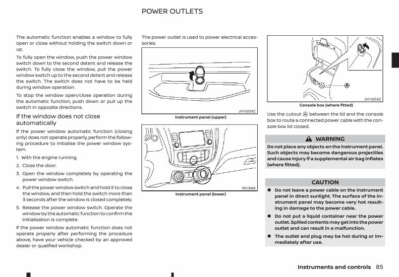
The automatic function enables a window to fullyopen or close without holding the switch down orup.
To fully open the window, push the power windowswitch down to the second detent and release theswitch. To fully close the window, pull the powerwindow switch up to the second detent and releasethe switch. The switch does not have to be heldduring window operation.
To stop the window open/close operation duringthe automatic function, push down or pull up theswitch in opposite directions.
If the window does not closeautomaticallyIf the power window automatic function (closingonly) does not operate properly, perform the follow-ing procedure to initialise the power window sys-tem.
1. With the engine running.
2. Close the door.
3. Open the window completely by operating thepower window switch.
4. Pull the power window switch and hold it to closethe window, and then hold the switch more than3 seconds after the window is closed completely.
5. Release the power window switch. Operate thewindow by the automatic function to confirm theinitialisation is complete.
If the power window automatic function does notoperate properly after performing the procedureabove, have your vehicle checked by an approveddealer or qualified workshop.
The power outlet is used to power electrical acces-sories.
Use the cutoutjA between the lid and the consolebox to route a connected power cable with the con-sole box lid closed.
WARNINGDo not place any objects on the instrument panel.Such objects may become dangerous projectilesand cause injury if a supplemental air bag inflates(where fitted).
CAUTION• Do not leave a power cable on the instrument
panel in direct sunlight. The surface of the in-strument panel may become very hot result-ing in damage to the power cable.
• Do not put a liquid container near the poweroutlet. Spilled contents may get into the poweroutlet and can result in a malfunction.
• The outlet and plug may be hot during or im-mediately after use.
JVI1023XZ
Instrument panel (upper)
NIC3668
Instrument panel (lower)
JVI1025XZ
Console box (where fitted)
POWER OUTLETS
Instruments and controls 85
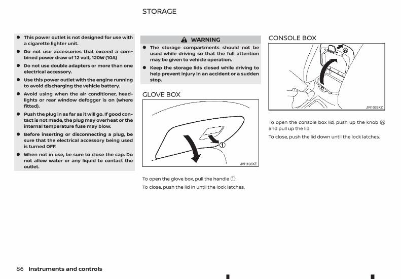
• This power outlet is not designed for use witha cigarette lighter unit.
• Do not use accessories that exceed a com-bined power draw of 12 volt, 120W (10A)
• Do not use double adapters or more than oneelectrical accessory.
• Use this power outlet with the engine runningto avoid discharging the vehicle battery.
• Avoid using when the air conditioner, head-lights or rear window defogger is on (wherefitted).
• Push the plug in as far as it will go. If good con-tact is not made, the plug may overheat or theinternal temperature fuse may blow.
• Before inserting or disconnecting a plug, besure that the electrical accessory being usedis turned OFF.
• When not in use, be sure to close the cap. Donot allow water or any liquid to contact theoutlet.
WARNING• The storage compartments should not be
used while driving so that the full attentionmay be given to vehicle operation.
• Keep the storage lids closed while driving tohelp prevent injury in an accident or a suddenstop.
GLOVE BOX
To open the glove box, pull the handle ➀.
To close, push the lid in until the lock latches.
CONSOLE BOX
To open the console box lid, push up the knob jAand pull up the lid.
To close, push the lid down until the lock latches.
JVI1102XZ
JVI1026XZ
STORAGE
86 Instruments and controls
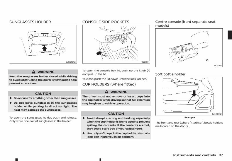
SUNGLASSES HOLDER
WARNINGKeep the sunglasses holder closed while drivingto avoid obstructing the driver's view and to helpprevent an accident.
CAUTION• Do not use for anything other than sunglasses.
• Do not leave sunglasses in the sunglassesholder while parking in direct sunlight. Theheat may damage the sunglasses.
To open the sunglasses holder, push and release.Only store one pair of sunglasses in the holder.
CONSOLE SIDE POCKETS
To open the console box lid, push up the knob jAand pull up the lid.
To close, push the lid down until the lock latches.
CUP HOLDERS (where fitted)
WARNINGThe driver must not remove or insert cups intothe cup holder while driving so that full attentionmay be given to vehicle operation.
CAUTION• Avoid abrupt starting and braking especially
when the cup holder is being used to preventspilling the contents. If the contents are hot,they could scald you or your passengers.
• Use only soft cups in the cup holder. Hard ob-jects can injure you in an accident.
Centre console (front separate seatmodels)
Soft bottle holder
The front and rear (where fitted) soft bottle holdersare located on the doors.
JVI0619XZ NIC3099
NIC3100
JVI1241XZ
Example
Instruments and controls 87
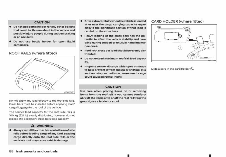
CAUTION• Do not use bottle holder for any other objects
that could be thrown about in the vehicle andpossibly injure people during sudden brakingor an accident.
• Do not use bottle holder for open liquidcontainers.
ROOF RAILS (where fitted)
Do not apply any load directly to the roof side rails.Cross bars must be installed before applying load/cargo/luggage to the roof of the vehicle.
The service load capacity for the roof side rails is100 kg (221 lb) evenly distributed, however do notexceed the accessory cross bars load capacity.
WARNING• Always install the cross bars onto the roof side
rails before loading cargo of any kind. Loadingcargo directly onto the roof side rails or thevehicle’s roof may cause vehicle damage.
• Drive extra carefully when the vehicle is loadedat or near the cargo carrying capacity, espe-cially if the significant portion of that load iscarried on the cross bars.
• Heavy loading of the cross bars has the po-tential to affect the vehicle stability and han-dling during sudden or unusual handling ma-noeuvres.
• Roof rack cross bar load should be evenly dis-tributed.
• Do not exceed maximum roof rail load capac-ity.
• Properly secure all cargo with ropes or strapsto help prevent it from sliding or shifting. In asudden stop or collision, unsecured cargocould cause personal injury.
CAUTIONUse care when placing items on or removingitems from the roof rail. If you cannot comfort-ably lift the items onto or off the roof rail from theground, use a ladder or stool.
CARD HOLDER (where fitted)
Slide a card in the card holderjA .
JVI1103XZ
NPA1569
88 Instruments and controls
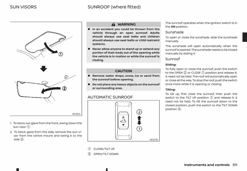
1. To block out glare from the front, swing down thesun visor ➀.
2. To block glare from the side, remove the sun vi-sor from the centre mount and swing it to theside ➁.
WARNING• In an accident you could be thrown from the
vehicle through an open sunroof. Adultsshould always use seat belts and childrenshould always use seat belts or child restraintsystems.
• Never allow anyone to stand up or extend anyportion of their body out of the opening whilethe vehicle is in motion or while the sunroof isclosing.
CAUTION• Remove water drops, snow, ice or sand from
the sunroof before opening.
• Do not place any heavy objects on the sunroofor surrounding area.
AUTOMATIC SUNROOF
➀ CLOSE/TILT UP
➁ OPEN/TILT DOWN
The sunroof operates when the ignition switch is inthe ON position.
SunshadeTo open or close the sunshade, slide the sunshademanually.
The sunshade will open automatically when thesunroof is opened. The sunshade needs to be closedmanually by sliding it.
SunroofSliding:To fully open or close the sunroof, push the switchto the OPEN ➁ or CLOSE ➀ position and release it;it need not be held. The roof will automatically openor close all the way. To stop the roof, push the switchonce more while it is opening or closing.
Tilting:To tilt up, first close the sunroof, then push theswitch to the TILT UP position ➀ and release it; itneed not be held. To tilt the sunroof down to theclosed position, push the switch to the TILT DOWNposition ➁.
SIC2872
NIC2733
SUN VISORS SUNROOF (where fitted)
Instruments and controls 89
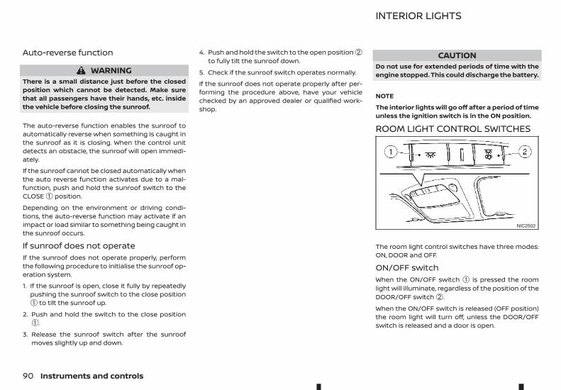
Auto-reverse function
WARNINGThere is a small distance just before the closedposition which cannot be detected. Make surethat all passengers have their hands, etc. insidethe vehicle before closing the sunroof.
The auto-reverse function enables the sunroof toautomatically reverse when something is caught inthe sunroof as it is closing. When the control unitdetects an obstacle, the sunroof will open immedi-ately.
If the sunroof cannot be closed automatically whenthe auto reverse function activates due to a mal-function, push and hold the sunroof switch to theCLOSE ➀ position.
Depending on the environment or driving condi-tions, the auto-reverse function may activate if animpact or load similar to something being caught inthe sunroof occurs.
If sunroof does not operateIf the sunroof does not operate properly, performthe following procedure to initialise the sunroof op-eration system.
1. If the sunroof is open, close it fully by repeatedlypushing the sunroof switch to the close position➀ to tilt the sunroof up.
2. Push and hold the switch to the close position➀.
3. Release the sunroof switch after the sunroofmoves slightly up and down.
4. Push and hold the switch to the open position ➁to fully tilt the sunroof down.
5. Check if the sunroof switch operates normally.
If the sunroof does not operate properly after per-forming the procedure above, have your vehiclechecked by an approved dealer or qualified work-shop.
CAUTIONDo not use for extended periods of time with theengine stopped. This could discharge the battery.
NOTE
The interior lights will go off after a period of timeunless the ignition switch is in the ON position.
ROOM LIGHT CONTROL SWITCHES
The room light control switches have three modes:ON, DOOR and OFF.
ON/OFF switchWhen the ON/OFF switch ➀ is pressed the roomlight will illuminate, regardless of the position of theDOOR/OFF switch ➁.
When the ON/OFF switch is released (OFF position)the room light will turn off, unless the DOOR/OFFswitch is released and a door is open.
NIC2502
INTERIOR LIGHTS
90 Instruments and controls
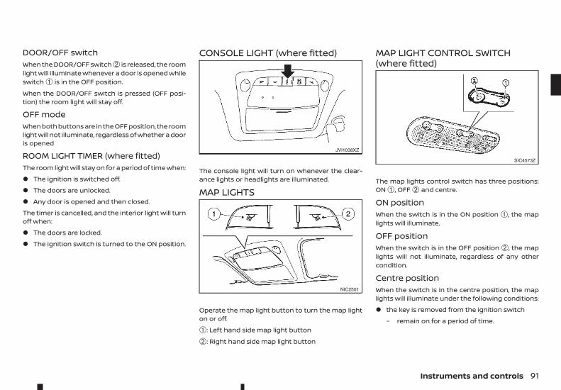
DOOR/OFF switchWhen the DOOR/OFF switch ➁ is released, the roomlight will illuminate whenever a door is opened whileswitch ➀ is in the OFF position.
When the DOOR/OFF switch is pressed (OFF posi-tion) the room light will stay off.
OFF modeWhen both buttons are in the OFF position, the roomlight will not illuminate, regardless of whether a dooris opened
ROOM LIGHT TIMER (where fitted)The room light will stay on for a period of time when:
• The ignition is switched off.
• The doors are unlocked.
• Any door is opened and then closed.
The timer is cancelled, and the interior light will turnoff when:
• The doors are locked.
• The ignition switch is turned to the ON position.
CONSOLE LIGHT (where fitted)
The console light will turn on whenever the clear-ance lights or headlights are illuminated.
MAP LIGHTS
Operate the map light button to turn the map lighton or off.
➀: Left hand side map light button
➁: Right hand side map light button
MAP LIGHT CONTROL SWITCH(where fitted)
The map lights control switch has three positions:ON ➀, OFF ➁ and centre.
ON positionWhen the switch is in the ON position ➀, the maplights will illuminate.
OFF positionWhen the switch is in the OFF position ➁, the maplights will not illuminate, regardless of any othercondition.
Centre positionWhen the switch is in the centre position, the maplights will illuminate under the following conditions:
• the key is removed from the ignition switch
– remain on for a period of time.
JVI1038XZ
NIC2501
SIC4573Z
Instruments and controls 91
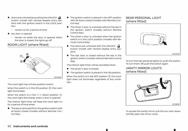
• doors are unlocked by pushing the UNLOCKbutton (model with remote keyless entry sys-tem) with the ignition switch in the LOCK posi-tion
– remain on for a period of time.
• any door is opened
– remain on while the door is opened. Whenthe door is closed, the lights go off.
ROOM LIGHT (where fitted)
The room light has a three-position switch.
When the switch is in the ON position ➁, the roomlight illuminates.
When the switch is in the <$> (Door) position ➀,the room light illuminates when a door is opened.
The interior light timer will keep the room light onfor a period of time when:
• The key is removed from the ignition switch withall doors closed (models without Remote Con-trol Key).
• The ignition switch is placed in the OFF positionwith all doors closed (models with Remote Con-trol Key).
• The driver's door is unlocked without the key inthe ignition switch (models without RemoteControl Key).
• The driver's door is unlocked when the ignitionswitch is in the LOCK position (models with Re-mote Control Key).
• The doors are unlocked with the UNLOCKbutton (model with remote keyless entry sys-tem).
• The last door is closed without the key in theignition switch (models without Remote ControlKey).
The interior light timer will be cancelled when:
• The driver's door is locked.
• The ignition switch is placed in the ON position.
When the switch is in the OFF position ➂, the roomlight does not illuminate, regardless of any condi-tion.
REAR PERSONAL LIGHT(where fitted)
To turn the rear personal lights on, push the switch.To turn them off, push the switch again.
VANITY MIRROR LIGHTS(where fitted)
To access the vanity mirror, pull the sun visor downand flip open the mirror cover.
SIC2489Z
SIC3250Z
SIC3869Z
92 Instruments and controls
The vanity mirror light illuminates when the vanitymirror cover is opened. When the cover is closed,the light will turn off.
BATTERY SAVER SYSTEMThe lights will turn off after a period of time whenthe lights remain illuminated to prevent the batteryfrom becoming discharged.
Instruments and controls 93

NOTE
94 Instruments and controls
3 Pre-driving checks and adjustmentsPre-driving checks and adjustments
Keys ........................................................................................................................ 96Key (where fitted)................................................................................. 96Anti-Theft System (ATS*) key (where fitted)..................... 96Remote Control Key (where fitted)......................................... 96
Doors..................................................................................................................... 98Locking with key................................................................................... 98Opening with inside door handle............................................ 98Locking with power door lock switch.................................. 98Child safety rear door locks (Double Cabmodels)........................................................................................................ 99
Remote keyless entry system (where fitted)........................... 99Using remote keyless entry system ...................................... 100
Remote Control Key system (where fitted) .............................. 101Remote Control Key operating range.................................. 102Using Remote Control Key system......................................... 102Battery saver system........................................................................ 104Warning and audible reminders ............................................... 104Troubleshooting guide .................................................................... 106Using remote keyless entry system ...................................... 108Hazard indicator and horn operation .................................. 109
Security system (where fitted)........................................................... 110Theft warning system (where fitted).................................... 110
Anti-Theft System (ATS) .................................................................. 110Bonnet.................................................................................................................. 111
Opening bonnet ................................................................................... 112Closing bonnet ...................................................................................... 112
Fuel filler lid and cap .................................................................................. 112Opening fuel filler lid.......................................................................... 113Fuel filler cap............................................................................................ 113
AdBlue® filler lid and cap ........................................................................ 114Opening AdBlue® filler lid............................................................... 114Locking AdBlue® filler lid................................................................. 114AdBlue® filler cap.................................................................................. 114
Cargo bed (where fitted) ........................................................................ 115Tailgate ........................................................................................................ 115Tie down hooks (where fitted)................................................... 115C-Channel system (where fitted)............................................. 116
Steering wheel ............................................................................................... 118Steering wheel adjustment.......................................................... 118
Mirrors .................................................................................................................. 118Inside rearview mirror ...................................................................... 118Outside rearview mirrors............................................................... 120Vanity mirror (where fitted).......................................................... 121
Parking brake.................................................................................................. 121
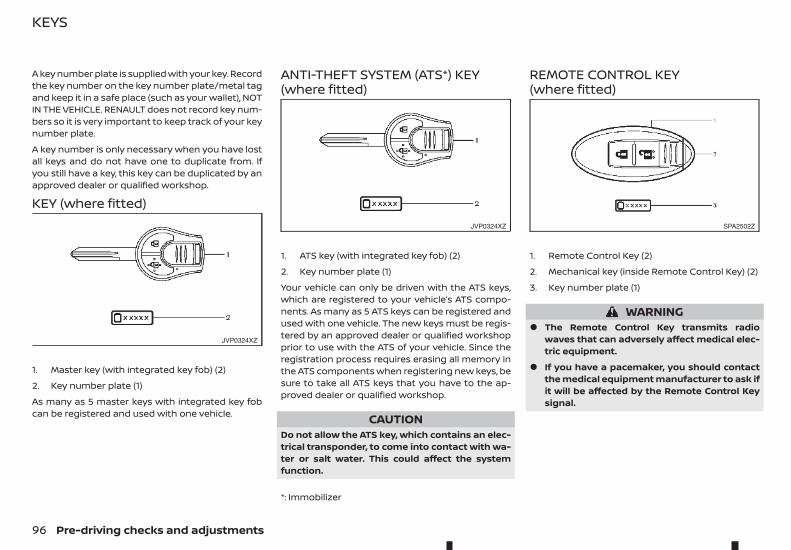
A key number plate is supplied with your key. Recordthe key number on the key number plate/metal tagand keep it in a safe place (such as your wallet), NOTIN THE VEHICLE. RENAULT does not record key num-bers so it is very important to keep track of your keynumber plate.
A key number is only necessary when you have lostall keys and do not have one to duplicate from. Ifyou still have a key, this key can be duplicated by anapproved dealer or qualified workshop.
KEY (where fitted)
1. Master key (with integrated key fob) (2)
2. Key number plate (1)
As many as 5 master keys with integrated key fobcan be registered and used with one vehicle.
ANTI-THEFT SYSTEM (ATS*) KEY(where fitted)
1. ATS key (with integrated key fob) (2)
2. Key number plate (1)
Your vehicle can only be driven with the ATS keys,which are registered to your vehicle’s ATS compo-nents. As many as 5 ATS keys can be registered andused with one vehicle. The new keys must be regis-tered by an approved dealer or qualified workshopprior to use with the ATS of your vehicle. Since theregistration process requires erasing all memory inthe ATS components when registering new keys, besure to take all ATS keys that you have to the ap-proved dealer or qualified workshop.
CAUTIONDo not allow the ATS key, which contains an elec-trical transponder, to come into contact with wa-ter or salt water. This could affect the systemfunction.
*: Immobilizer
REMOTE CONTROL KEY(where fitted)
1. Remote Control Key (2)
2. Mechanical key (inside Remote Control Key) (2)
3. Key number plate (1)
WARNING• The Remote Control Key transmits radio
waves that can adversely affect medical elec-tric equipment.
• If you have a pacemaker, you should contactthe medical equipment manufacturer to ask ifit will be affected by the Remote Control Keysignal.
JVP0324XZ
JVP0324XZ SPA2502Z
KEYS
96 Pre-driving checks and adjustments
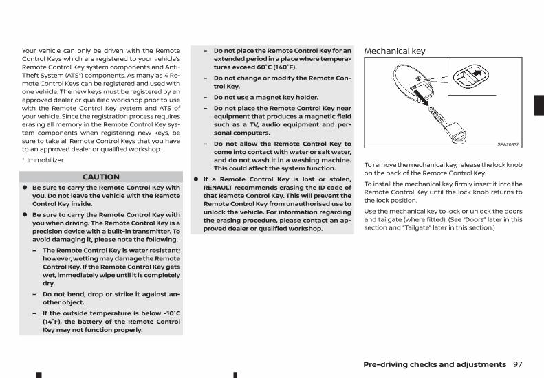
Your vehicle can only be driven with the RemoteControl Keys which are registered to your vehicle’sRemote Control Key system components and Anti-Theft System (ATS*) components. As many as 4 Re-mote Control Keys can be registered and used withone vehicle. The new keys must be registered by anapproved dealer or qualified workshop prior to usewith the Remote Control Key system and ATS ofyour vehicle. Since the registration process requireserasing all memory in the Remote Control Key sys-tem components when registering new keys, besure to take all Remote Control Keys that you haveto an approved dealer or qualified workshop.
*: Immobilizer
CAUTION• Be sure to carry the Remote Control Key with
you. Do not leave the vehicle with the RemoteControl Key inside.
• Be sure to carry the Remote Control Key withyou when driving. The Remote Control Key is aprecision device with a built-in transmitter. Toavoid damaging it, please note the following.
– The Remote Control Key is water resistant;however, wetting may damage the RemoteControl Key. If the Remote Control Key getswet, immediately wipe until it is completelydry.
– Do not bend, drop or strike it against an-other object.
– If the outside temperature is below -10°C(14°F), the battery of the Remote ControlKey may not function properly.
– Do not place the Remote Control Key for anextended period in a place where tempera-tures exceed 60°C (140°F).
– Do not change or modify the Remote Con-trol Key.
– Do not use a magnet key holder.
– Do not place the Remote Control Key nearequipment that produces a magnetic fieldsuch as a TV, audio equipment and per-sonal computers.
– Do not allow the Remote Control Key tocome into contact with water or salt water,and do not wash it in a washing machine.This could affect the system function.
• If a Remote Control Key is lost or stolen,RENAULT recommends erasing the ID code ofthat Remote Control Key. This will prevent theRemote Control Key from unauthorised use tounlock the vehicle. For information regardingthe erasing procedure, please contact an ap-proved dealer or qualified workshop.
Mechanical key
To remove the mechanical key, release the lock knobon the back of the Remote Control Key.
To install the mechanical key, firmly insert it into theRemote Control Key until the lock knob returns tothe lock position.
Use the mechanical key to lock or unlock the doorsand tailgate (where fitted). (See “Doors” later in thissection and “Tailgate” later in this section.)
SPA2033Z
Pre-driving checks and adjustments 97
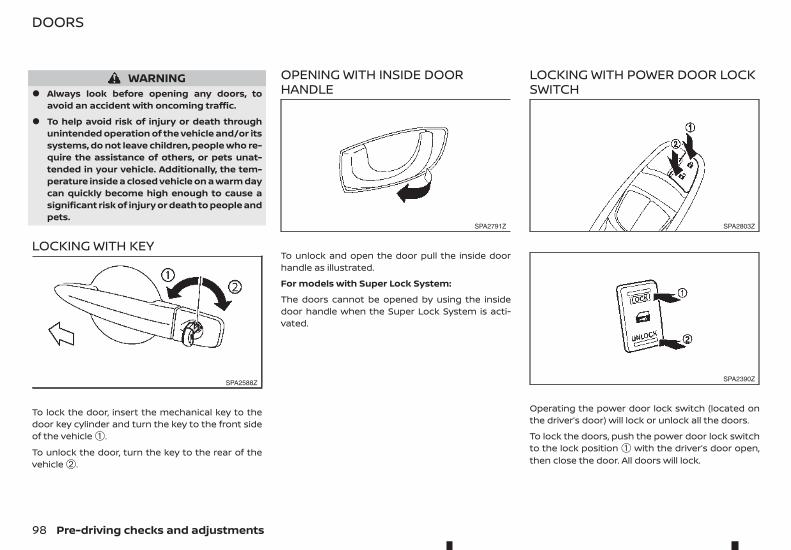
WARNING• Always look before opening any doors, to
avoid an accident with oncoming traffic.
• To help avoid risk of injury or death throughunintended operation of the vehicle and/or itssystems, do not leave children, people who re-quire the assistance of others, or pets unat-tended in your vehicle. Additionally, the tem-perature inside a closed vehicle on a warm daycan quickly become high enough to cause asignificant risk of injury or death to people andpets.
LOCKING WITH KEY
To lock the door, insert the mechanical key to thedoor key cylinder and turn the key to the front sideof the vehicle ➀.
To unlock the door, turn the key to the rear of thevehicle ➁.
OPENING WITH INSIDE DOORHANDLE
To unlock and open the door pull the inside doorhandle as illustrated.
For models with Super Lock System:
The doors cannot be opened by using the insidedoor handle when the Super Lock System is acti-vated.
LOCKING WITH POWER DOOR LOCKSWITCH
Operating the power door lock switch (located onthe driver’s door) will lock or unlock all the doors.
To lock the doors, push the power door lock switchto the lock position ➀ with the driver’s door open,then close the door. All doors will lock.
SPA2588Z
SPA2791Z SPA2803Z
SPA2390Z
DOORS
98 Pre-driving checks and adjustments
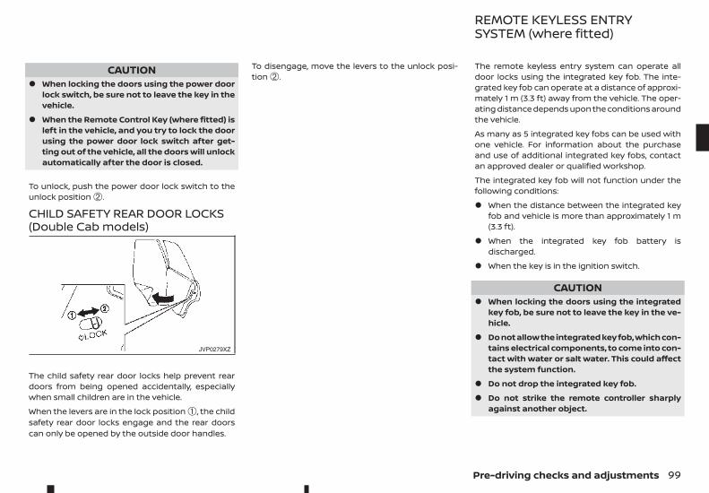
CAUTION• When locking the doors using the power door
lock switch, be sure not to leave the key in thevehicle.
• When the Remote Control Key (where fitted) isleft in the vehicle, and you try to lock the doorusing the power door lock switch after get-ting out of the vehicle, all the doors will unlockautomatically after the door is closed.
To unlock, push the power door lock switch to theunlock position ➁.
CHILD SAFETY REAR DOOR LOCKS(Double Cab models)
The child safety rear door locks help prevent reardoors from being opened accidentally, especiallywhen small children are in the vehicle.
When the levers are in the lock position ➀, the childsafety rear door locks engage and the rear doorscan only be opened by the outside door handles.
To disengage, move the levers to the unlock posi-tion ➁.
The remote keyless entry system can operate alldoor locks using the integrated key fob. The inte-grated key fob can operate at a distance of approxi-mately 1 m (3.3 ft) away from the vehicle. The oper-ating distance depends upon the conditions aroundthe vehicle.
As many as 5 integrated key fobs can be used withone vehicle. For information about the purchaseand use of additional integrated key fobs, contactan approved dealer or qualified workshop.
The integrated key fob will not function under thefollowing conditions:
• When the distance between the integrated keyfob and vehicle is more than approximately 1 m(3.3 ft).
• When the integrated key fob battery isdischarged.
• When the key is in the ignition switch.
CAUTION• When locking the doors using the integrated
key fob, be sure not to leave the key in the ve-hicle.
• Do not allow the integrated key fob, which con-tains electrical components, to come into con-tact with water or salt water. This could affectthe system function.
• Do not drop the integrated key fob.
• Do not strike the remote controller sharplyagainst another object.
JVP0279XZ
REMOTE KEYLESS ENTRYSYSTEM (where fitted)
Pre-driving checks and adjustments 99
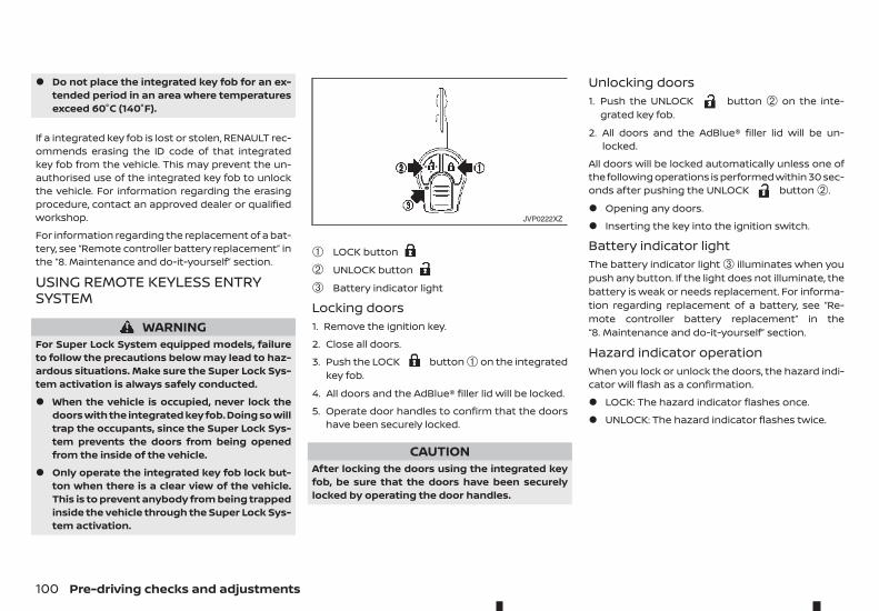
• Do not place the integrated key fob for an ex-tended period in an area where temperaturesexceed 60°C (140°F).
If a integrated key fob is lost or stolen, RENAULT rec-ommends erasing the ID code of that integratedkey fob from the vehicle. This may prevent the un-authorised use of the integrated key fob to unlockthe vehicle. For information regarding the erasingprocedure, contact an approved dealer or qualifiedworkshop.
For information regarding the replacement of a bat-tery, see “Remote controller battery replacement” inthe “8. Maintenance and do-it-yourself” section.
USING REMOTE KEYLESS ENTRYSYSTEM
WARNINGFor Super Lock System equipped models, failureto follow the precautions below may lead to haz-ardous situations. Make sure the Super Lock Sys-tem activation is always safely conducted.
• When the vehicle is occupied, never lock thedoors with the integrated key fob. Doing so willtrap the occupants, since the Super Lock Sys-tem prevents the doors from being openedfrom the inside of the vehicle.
• Only operate the integrated key fob lock but-ton when there is a clear view of the vehicle.This is to prevent anybody from being trappedinside the vehicle through the Super Lock Sys-tem activation.
➀ LOCK button
➁ UNLOCK button
➂ Battery indicator light
Locking doors1. Remove the ignition key.
2. Close all doors.
3. Push the LOCK button ➀ on the integratedkey fob.
4. All doors and the AdBlue® filler lid will be locked.
5. Operate door handles to confirm that the doorshave been securely locked.
CAUTIONAfter locking the doors using the integrated keyfob, be sure that the doors have been securelylocked by operating the door handles.
Unlocking doors1. Push the UNLOCK button ➁ on the inte-
grated key fob.
2. All doors and the AdBlue® filler lid will be un-locked.
All doors will be locked automatically unless one ofthe following operations is performed within 30 sec-onds after pushing the UNLOCK button ➁.
• Opening any doors.
• Inserting the key into the ignition switch.
Battery indicator lightThe battery indicator light ➂ illuminates when youpush any button. If the light does not illuminate, thebattery is weak or needs replacement. For informa-tion regarding replacement of a battery, see “Re-mote controller battery replacement” in the“8. Maintenance and do-it-yourself” section.
Hazard indicator operationWhen you lock or unlock the doors, the hazard indi-cator will flash as a confirmation.
• LOCK: The hazard indicator flashes once.
• UNLOCK: The hazard indicator flashes twice.
JVP0222XZ
100 Pre-driving checks and adjustments
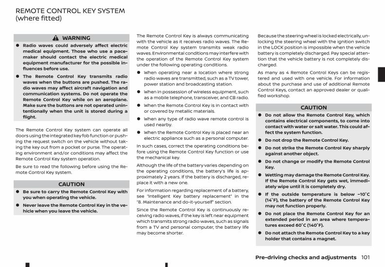
WARNING• Radio waves could adversely affect electric
medical equipment. Those who use a pace-maker should contact the electric medicalequipment manufacturer for the possible in-fluences before use.
• The Remote Control Key transmits radiowaves when the buttons are pushed. The ra-dio waves may affect aircraft navigation andcommunication systems. Do not operate theRemote Control Key while on an aeroplane.Make sure the buttons are not operated unin-tentionally when the unit is stored during aflight.
The Remote Control Key system can operate alldoors using the integrated key fob function or push-ing the request switch on the vehicle without tak-ing the key out from a pocket or purse. The operat-ing environment and/or conditions may affect theRemote Control Key system operation.
Be sure to read the following before using the Re-mote Control Key system.
CAUTION• Be sure to carry the Remote Control Key with
you when operating the vehicle.
• Never leave the Remote Control Key in the ve-hicle when you leave the vehicle.
The Remote Control Key is always communicatingwith the vehicle as it receives radio waves. The Re-mote Control Key system transmits weak radiowaves. Environmental conditions may interfere withthe operation of the Remote Control Key systemunder the following operating conditions.
• When operating near a location where strongradio waves are transmitted, such as a TV tower,power station and broadcasting station.
• When in possession of wireless equipment, suchas a mobile telephone, transceiver, and CB radio.
• When the Remote Control Key is in contact withor covered by metallic materials.
• When any type of radio wave remote control isused nearby.
• When the Remote Control Key is placed near anelectric appliance such as a personal computer.
In such cases, correct the operating conditions be-fore using the Remote Control Key function or usethe mechanical key.
Although the life of the battery varies depending onthe operating conditions, the battery’s life is ap-proximately 2 years. If the battery is discharged, re-place it with a new one.
For information regarding replacement of a battery,see “Intelligent Key battery replacement” in the“8. Maintenance and do-it-yourself” section.
Since the Remote Control Key is continuously re-ceiving radio waves, if the key is left near equipmentwhich transmits strong radio waves, such as signalsfrom a TV and personal computer, the battery lifemay become shorter.
Because the steering wheel is locked electrically, un-locking the steering wheel with the ignition switchin the LOCK position is impossible when the vehiclebattery is completely discharged. Pay special atten-tion that the vehicle battery is not completely dis-charged.
As many as 4 Remote Control Keys can be regis-tered and used with one vehicle. For informationabout the purchase and use of additional RemoteControl Keys, contact an approved dealer or quali-fied workshop.
CAUTION• Do not allow the Remote Control Key, which
contains electrical components, to come intocontact with water or salt water. This could af-fect the system function.
• Do not drop the Remote Control Key.
• Do not strike the Remote Control Key sharplyagainst another object.
• Do not change or modify the Remote ControlKey.
• Wetting may damage the Remote Control Key.If the Remote Control Key gets wet, immedi-ately wipe until it is completely dry.
• If the outside temperature is below −10°C(14°F), the battery of the Remote Control Keymay not function properly.
• Do not place the Remote Control Key for anextended period in an area where tempera-tures exceed 60°C (140°F).
• Do not attach the Remote Control Key to a keyholder that contains a magnet.
REMOTE CONTROL KEY SYSTEM(where fitted)
Pre-driving checks and adjustments 101
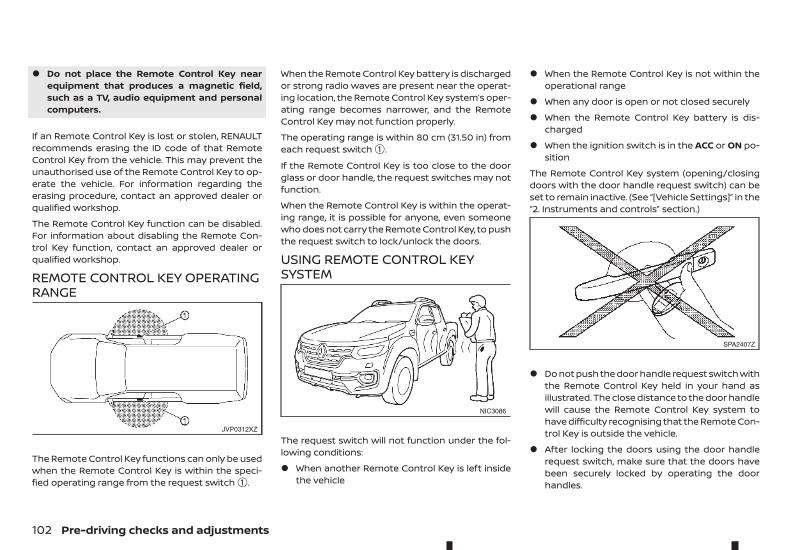
• Do not place the Remote Control Key nearequipment that produces a magnetic field,such as a TV, audio equipment and personalcomputers.
If an Remote Control Key is lost or stolen, RENAULTrecommends erasing the ID code of that RemoteControl Key from the vehicle. This may prevent theunauthorised use of the Remote Control Key to op-erate the vehicle. For information regarding theerasing procedure, contact an approved dealer orqualified workshop.
The Remote Control Key function can be disabled.For information about disabling the Remote Con-trol Key function, contact an approved dealer orqualified workshop.
REMOTE CONTROL KEY OPERATINGRANGE
The Remote Control Key functions can only be usedwhen the Remote Control Key is within the speci-fied operating range from the request switch ➀.
When the Remote Control Key battery is dischargedor strong radio waves are present near the operat-ing location, the Remote Control Key system’s oper-ating range becomes narrower, and the RemoteControl Key may not function properly.
The operating range is within 80 cm (31.50 in) fromeach request switch ➀.
If the Remote Control Key is too close to the doorglass or door handle, the request switches may notfunction.
When the Remote Control Key is within the operat-ing range, it is possible for anyone, even someonewho does not carry the Remote Control Key, to pushthe request switch to lock/unlock the doors.
USING REMOTE CONTROL KEYSYSTEM
The request switch will not function under the fol-lowing conditions:
• When another Remote Control Key is left insidethe vehicle
• When the Remote Control Key is not within theoperational range
• When any door is open or not closed securely
• When the Remote Control Key battery is dis-charged
• When the ignition switch is in the ACC or ON po-sition
The Remote Control Key system (opening/closingdoors with the door handle request switch) can beset to remain inactive. (See “[Vehicle Settings]” in the“2. Instruments and controls” section.)
• Do not push the door handle request switch withthe Remote Control Key held in your hand asillustrated. The close distance to the door handlewill cause the Remote Control Key system tohave difficulty recognising that the Remote Con-trol Key is outside the vehicle.
• After locking the doors using the door handlerequest switch, make sure that the doors havebeen securely locked by operating the doorhandles.
JVP0312XZ
NIC3086
SPA2407Z
102 Pre-driving checks and adjustments
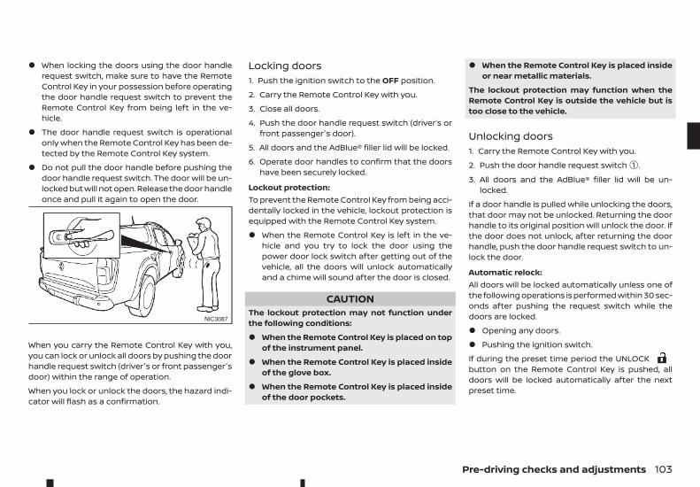
• When locking the doors using the door handlerequest switch, make sure to have the RemoteControl Key in your possession before operatingthe door handle request switch to prevent theRemote Control Key from being left in the ve-hicle.
• The door handle request switch is operationalonly when the Remote Control Key has been de-tected by the Remote Control Key system.
• Do not pull the door handle before pushing thedoor handle request switch. The door will be un-locked but will not open. Release the door handleonce and pull it again to open the door.
When you carry the Remote Control Key with you,you can lock or unlock all doors by pushing the doorhandle request switch (driver's or front passenger'sdoor) within the range of operation.
When you lock or unlock the doors, the hazard indi-cator will flash as a confirmation.
Locking doors1. Push the ignition switch to the OFF position.
2. Carry the Remote Control Key with you.
3. Close all doors.
4. Push the door handle request switch (driver’s orfront passenger's door).
5. All doors and the AdBlue® filler lid will be locked.
6. Operate door handles to confirm that the doorshave been securely locked.
Lockout protection:To prevent the Remote Control Key from being acci-dentally locked in the vehicle, lockout protection isequipped with the Remote Control Key system.
• When the Remote Control Key is left in the ve-hicle and you try to lock the door using thepower door lock switch after getting out of thevehicle, all the doors will unlock automaticallyand a chime will sound after the door is closed.
CAUTIONThe lockout protection may not function underthe following conditions:
• When the Remote Control Key is placed on topof the instrument panel.
• When the Remote Control Key is placed insideof the glove box.
• When the Remote Control Key is placed insideof the door pockets.
• When the Remote Control Key is placed insideor near metallic materials.
The lockout protection may function when theRemote Control Key is outside the vehicle but istoo close to the vehicle.
Unlocking doors1. Carry the Remote Control Key with you.
2. Push the door handle request switch ➀.
3. All doors and the AdBlue® filler lid will be un-locked.
If a door handle is pulled while unlocking the doors,that door may not be unlocked. Returning the doorhandle to its original position will unlock the door. Ifthe door does not unlock, after returning the doorhandle, push the door handle request switch to un-lock the door.
Automatic relock:All doors will be locked automatically unless one ofthe following operations is performed within 30 sec-onds after pushing the request switch while thedoors are locked.
• Opening any doors.
• Pushing the ignition switch.
If during the preset time period the UNLOCKbutton on the Remote Control Key is pushed, alldoors will be locked automatically after the nextpreset time.
NIC3087
Pre-driving checks and adjustments 103
BATTERY SAVER SYSTEMWhen all the following conditions are met for a pe-riod of time, the battery saver system will cut off thepower supply to prevent battery discharge.
• The ignition switch is in the ACC or ON position.
• All doors are closed.
• The shift lever is in the P (Park) position (auto-matic transmission model).
WARNING AND AUDIBLE REMINDERSThe Remote Control Key system is equipped with afunction that is designed to minimise improper op-erations of the Remote Control Key and to help pre-vent the vehicle from being stolen. A chime or beepsounds inside and outside the vehicle and a warn-ing message appears in the vehicle information dis-play.
See the troubleshooting guide on the next page and“Vehicle information display” in the “2. Instrumentsand controls” section.
CAUTIONWhen the chime or beep sounds or the warningmessage appears, be sure to check both the ve-hicle and the Remote Control Key.
104 Pre-driving checks and adjustments

Pre-driving checks and adjustments 105
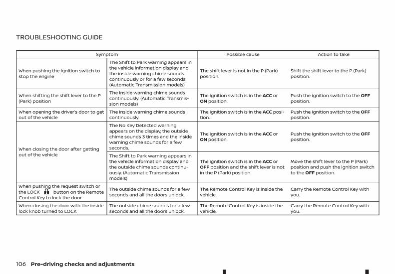
TROUBLESHOOTING GUIDE
Symptom Possible cause Action to take
When pushing the ignition switch tostop the engine
The Shift to Park warning appears inthe vehicle information display andthe inside warning chime soundscontinuously or for a few seconds.(Automatic Transmission models)
The shift lever is not in the P (Park)position.
Shift the shift lever to the P (Park)position.
When shifting the shift lever to the P(Park) position
The inside warning chime soundscontinuously. (Automatic Transmis-sion models)
The ignition switch is in the ACC orON position.
Push the ignition switch to the OFFposition.
When opening the driver’s door to getout of the vehicle
The inside warning chime soundscontinuously.
The ignition switch is in the ACC posi-tion.
Push the ignition switch to the OFFposition.
When closing the door after gettingout of the vehicle
The No Key Detected warningappears on the display, the outsidechime sounds 3 times and the insidewarning chime sounds for a fewseconds.
The ignition switch is in the ACC orON position.
Push the ignition switch to the OFFposition.
The Shift to Park warning appears inthe vehicle information display andthe outside chime sounds continu-ously. (Automatic Transmissionmodels)
The ignition switch is in the ACC orOFF position and the shift lever is notin the P (Park) position.
Move the shift lever to the P (Park)position and push the ignition switchto the OFF position.
When pushing the request switch orthe LOCK m button on the RemoteControl Key to lock the door
The outside chime sounds for a fewseconds and all the doors unlock.
The Remote Control Key is inside thevehicle.
Carry the Remote Control Key withyou.
When closing the door with the insidelock knob turned to LOCK
The outside chime sounds for a fewseconds and all the doors unlock.
The Remote Control Key is inside thevehicle.
Carry the Remote Control Key withyou.
106 Pre-driving checks and adjustments
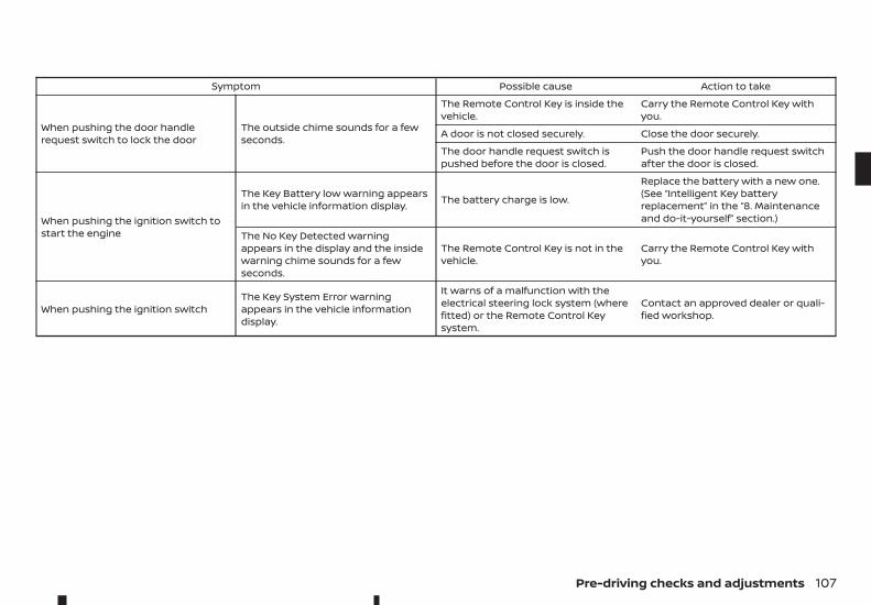
Symptom Possible cause Action to take
When pushing the door handlerequest switch to lock the door
The outside chime sounds for a fewseconds.
The Remote Control Key is inside thevehicle.
Carry the Remote Control Key withyou.
A door is not closed securely. Close the door securely.
The door handle request switch ispushed before the door is closed.
Push the door handle request switchafter the door is closed.
When pushing the ignition switch tostart the engine
The Key Battery low warning appearsin the vehicle information display. The battery charge is low.
Replace the battery with a new one.(See “Intelligent Key batteryreplacement” in the “8. Maintenanceand do-it-yourself” section.)
The No Key Detected warningappears in the display and the insidewarning chime sounds for a fewseconds.
The Remote Control Key is not in thevehicle.
Carry the Remote Control Key withyou.
When pushing the ignition switchThe Key System Error warningappears in the vehicle informationdisplay.
It warns of a malfunction with theelectrical steering lock system (wherefitted) or the Remote Control Keysystem.
Contact an approved dealer or quali-fied workshop.
Pre-driving checks and adjustments 107
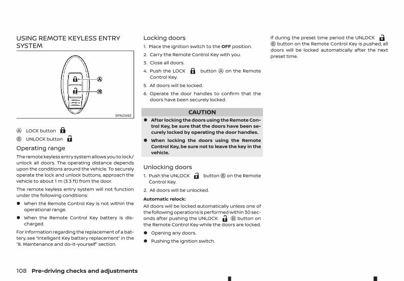
USING REMOTE KEYLESS ENTRYSYSTEM
jA LOCK buttonjB UNLOCK button
Operating rangeThe remote keyless entry system allows you to lock/unlock all doors. The operating distance dependsupon the conditions around the vehicle. To securelyoperate the lock and unlock buttons, approach thevehicle to about 1 m (3.3 ft) from the door.
The remote keyless entry system will not functionunder the following conditions:
• When the Remote Control Key is not within theoperational range.
• When the Remote Control Key battery is dis-charged.
For information regarding the replacement of a bat-tery, see “Intelligent Key battery replacement” in the“8. Maintenance and do-it-yourself” section.
Locking doors1. Place the ignition switch to the OFF position.
2. Carry the Remote Control Key with you.
3. Close all doors.
4. Push the LOCK button jA on the RemoteControl Key.
5. All doors will be locked.
6. Operate the door handles to confirm that thedoors have been securely locked.
CAUTION• After locking the doors using the Remote Con-
trol Key, be sure that the doors have been se-curely locked by operating the door handles.
• When locking the doors using the RemoteControl Key, be sure not to leave the key in thevehicle.
Unlocking doors1. Push the UNLOCK buttonjB on the Remote
Control Key.
2. All doors will be unlocked.
Automatic relock:All doors will be locked automatically unless one ofthe following operations is performed within 30 sec-onds after pushing the UNLOCK jB button onthe Remote Control Key while the doors are locked.
• Opening any doors.
• Pushing the ignition switch.
If during the preset time period the UNLOCKjB button on the Remote Control Key is pushed, alldoors will be locked automatically after the nextpreset time.
SPA2349Z
108 Pre-driving checks and adjustments
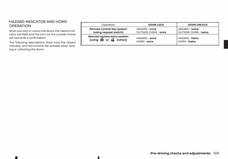
HAZARD INDICATOR AND HORNOPERATIONWhen you lock or unlock the doors, the hazard indi-cator will flash and the horn (or the outside chime)will sound as a confirmation.
The following descriptions show how the hazardindicator and horn/chime will activate when lock-ing or unlocking the doors.
Operation DOOR LOCK DOOR UNLOCKRemote Control Key system
(using request switch)HAZARD - onceOUTSIDE CHIME - once
HAZARD - twiceOUTSIDE CHIME - twice
Remote keyless entry system(using m or m button) HAZARD - once
HORN - onceHAZARD - twiceHORN - twice
Pre-driving checks and adjustments 109
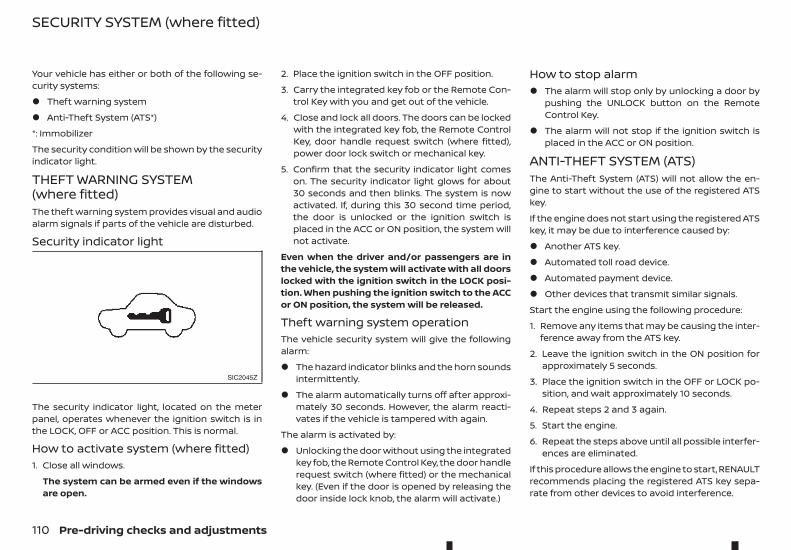
Your vehicle has either or both of the following se-curity systems:
• Theft warning system
• Anti-Theft System (ATS*)
*: Immobilizer
The security condition will be shown by the securityindicator light.
THEFT WARNING SYSTEM(where fitted)The theft warning system provides visual and audioalarm signals if parts of the vehicle are disturbed.
Security indicator light
The security indicator light, located on the meterpanel, operates whenever the ignition switch is inthe LOCK, OFF or ACC position. This is normal.
How to activate system (where fitted)1. Close all windows.
The system can be armed even if the windowsare open.
2. Place the ignition switch in the OFF position.
3. Carry the integrated key fob or the Remote Con-trol Key with you and get out of the vehicle.
4. Close and lock all doors. The doors can be lockedwith the integrated key fob, the Remote ControlKey, door handle request switch (where fitted),power door lock switch or mechanical key.
5. Confirm that the security indicator light comeson. The security indicator light glows for about30 seconds and then blinks. The system is nowactivated. If, during this 30 second time period,the door is unlocked or the ignition switch isplaced in the ACC or ON position, the system willnot activate.
Even when the driver and/or passengers are inthe vehicle, the system will activate with all doorslocked with the ignition switch in the LOCK posi-tion. When pushing the ignition switch to the ACCor ON position, the system will be released.
Theft warning system operationThe vehicle security system will give the followingalarm:
• The hazard indicator blinks and the horn soundsintermittently.
• The alarm automatically turns off after approxi-mately 30 seconds. However, the alarm reacti-vates if the vehicle is tampered with again.
The alarm is activated by:
• Unlocking the door without using the integratedkey fob, the Remote Control Key, the door handlerequest switch (where fitted) or the mechanicalkey. (Even if the door is opened by releasing thedoor inside lock knob, the alarm will activate.)
How to stop alarm• The alarm will stop only by unlocking a door by
pushing the UNLOCK button on the RemoteControl Key.
• The alarm will not stop if the ignition switch isplaced in the ACC or ON position.
ANTI-THEFT SYSTEM (ATS)The Anti-Theft System (ATS) will not allow the en-gine to start without the use of the registered ATSkey.
If the engine does not start using the registered ATSkey, it may be due to interference caused by:
• Another ATS key.
• Automated toll road device.
• Automated payment device.
• Other devices that transmit similar signals.
Start the engine using the following procedure:
1. Remove any items that may be causing the inter-ference away from the ATS key.
2. Leave the ignition switch in the ON position forapproximately 5 seconds.
3. Place the ignition switch in the OFF or LOCK po-sition, and wait approximately 10 seconds.
4. Repeat steps 2 and 3 again.
5. Start the engine.
6. Repeat the steps above until all possible interfer-ences are eliminated.
If this procedure allows the engine to start, RENAULTrecommends placing the registered ATS key sepa-rate from other devices to avoid interference.
SIC2045Z
SECURITY SYSTEM (where fitted)
110 Pre-driving checks and adjustments
If ATS is malfunctioning, this light will remain onwhile the ignition switch is in the ON position.
If the light remains on and/or the engine doesnot start, contact an approved dealer or qualifiedworkshop for ATS service as soon as possible. Besure to bring all Remote Control Keys that youhave when visiting an approved dealer for ser-vice.
WARNING• The bonnet must be closed and latched se-
curely before driving. Failure to do so couldcause the bonnet to fly open and result in anaccident.
• Never open the bonnet if steam or smoke iscoming from the engine compartment toavoid injury.
BONNET
Pre-driving checks and adjustments 111
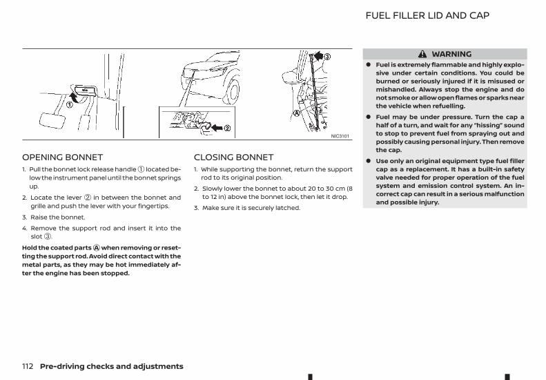
OPENING BONNET1. Pull the bonnet lock release handle ➀ located be-
low the instrument panel until the bonnet springsup.
2. Locate the lever ➁ in between the bonnet andgrille and push the lever with your fingertips.
3. Raise the bonnet.
4. Remove the support rod and insert it into theslot ➂.
Hold the coated partsjA when removing or reset-ting the support rod. Avoid direct contact with themetal parts, as they may be hot immediately af-ter the engine has been stopped.
CLOSING BONNET1. While supporting the bonnet, return the support
rod to its original position.
2. Slowly lower the bonnet to about 20 to 30 cm (8to 12 in) above the bonnet lock, then let it drop.
3. Make sure it is securely latched.
WARNING• Fuel is extremely flammable and highly explo-
sive under certain conditions. You could beburned or seriously injured if it is misused ormishandled. Always stop the engine and donot smoke or allow open flames or sparks nearthe vehicle when refuelling.
• Fuel may be under pressure. Turn the cap ahalf of a turn, and wait for any “hissing” soundto stop to prevent fuel from spraying out andpossibly causing personal injury. Then removethe cap.
• Use only an original equipment type fuel fillercap as a replacement. It has a built-in safetyvalve needed for proper operation of the fuelsystem and emission control system. An in-correct cap can result in a serious malfunctionand possible injury.
NIC3101
FUEL FILLER LID AND CAP
112 Pre-driving checks and adjustments
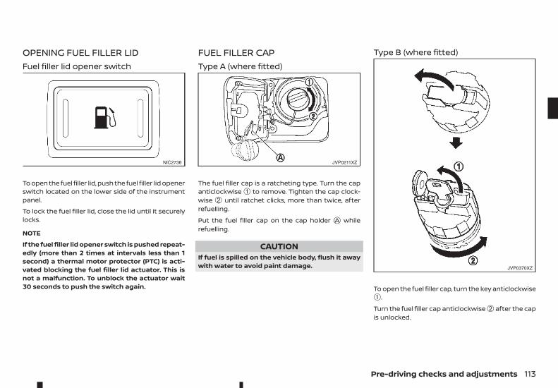
OPENING FUEL FILLER LIDFuel filler lid opener switch
To open the fuel filler lid, push the fuel filler lid openerswitch located on the lower side of the instrumentpanel.
To lock the fuel filler lid, close the lid until it securelylocks.
NOTE
If the fuel filler lid opener switch is pushed repeat-edly (more than 2 times at intervals less than 1second) a thermal motor protector (PTC) is acti-vated blocking the fuel filler lid actuator. This isnot a malfunction. To unblock the actuator wait30 seconds to push the switch again.
FUEL FILLER CAPType A (where fitted)
The fuel filler cap is a ratcheting type. Turn the capanticlockwise ➀ to remove. Tighten the cap clock-wise ➁ until ratchet clicks, more than twice, afterrefuelling.
Put the fuel filler cap on the cap holder jA whilerefuelling.
CAUTIONIf fuel is spilled on the vehicle body, flush it awaywith water to avoid paint damage.
Type B (where fitted)
To open the fuel filler cap, turn the key anticlockwise➀.
Turn the fuel filler cap anticlockwise ➁ after the capis unlocked.
NIC2736 JVP0211XZ
JVP0370XZ
Pre-driving checks and adjustments 113
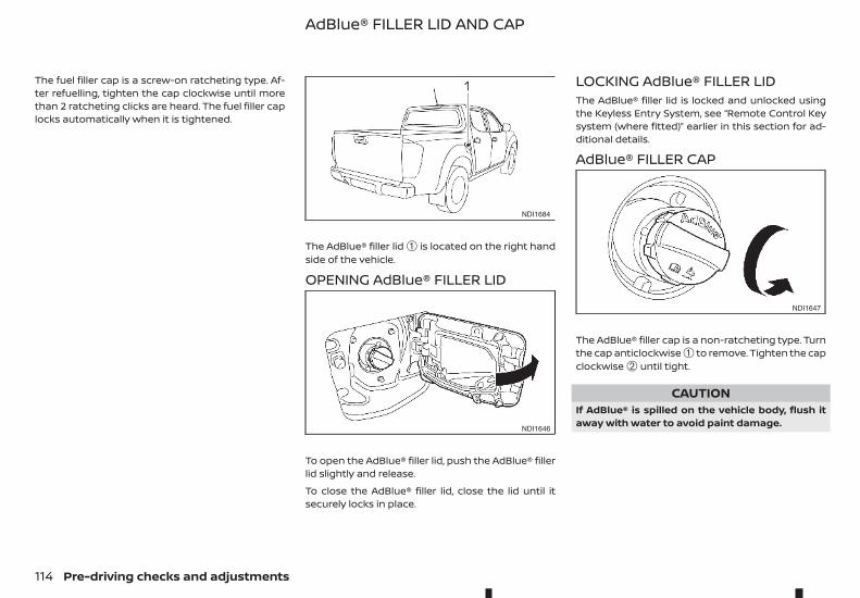
The fuel filler cap is a screw-on ratcheting type. Af-ter refuelling, tighten the cap clockwise until morethan 2 ratcheting clicks are heard. The fuel filler caplocks automatically when it is tightened.
The AdBlue® filler lid ➀ is located on the right handside of the vehicle.
OPENING AdBlue® FILLER LID
To open the AdBlue® filler lid, push the AdBlue® fillerlid slightly and release.
To close the AdBlue® filler lid, close the lid until itsecurely locks in place.
LOCKING AdBlue® FILLER LIDThe AdBlue® filler lid is locked and unlocked usingthe Keyless Entry System, see “Remote Control Keysystem (where fitted)” earlier in this section for ad-ditional details.
AdBlue® FILLER CAP
The AdBlue® filler cap is a non-ratcheting type. Turnthe cap anticlockwise ➀ to remove. Tighten the capclockwise ➁ until tight.
CAUTIONIf AdBlue® is spilled on the vehicle body, flush itaway with water to avoid paint damage.
NDI1684
NDI1646
NDI1647
AdBlue® FILLER LID AND CAP
114 Pre-driving checks and adjustments
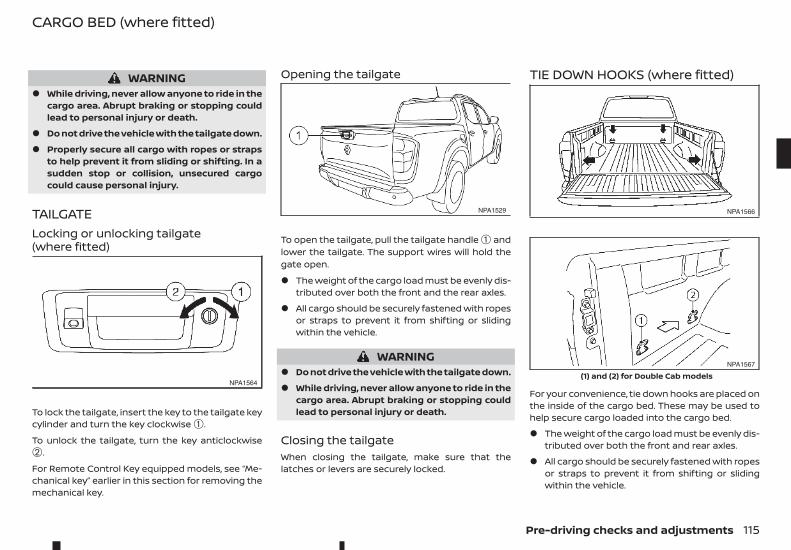
WARNING• While driving, never allow anyone to ride in the
cargo area. Abrupt braking or stopping couldlead to personal injury or death.
• Do not drive the vehicle with the tailgate down.
• Properly secure all cargo with ropes or strapsto help prevent it from sliding or shifting. In asudden stop or collision, unsecured cargocould cause personal injury.
TAILGATELocking or unlocking tailgate(where fitted)
To lock the tailgate, insert the key to the tailgate keycylinder and turn the key clockwise ➀.
To unlock the tailgate, turn the key anticlockwise➁.
For Remote Control Key equipped models, see “Me-chanical key” earlier in this section for removing themechanical key.
Opening the tailgate
To open the tailgate, pull the tailgate handle ➀ andlower the tailgate. The support wires will hold thegate open.
• The weight of the cargo load must be evenly dis-tributed over both the front and the rear axles.
• All cargo should be securely fastened with ropesor straps to prevent it from shifting or slidingwithin the vehicle.
WARNING• Do not drive the vehicle with the tailgate down.
• While driving, never allow anyone to ride in thecargo area. Abrupt braking or stopping couldlead to personal injury or death.
Closing the tailgateWhen closing the tailgate, make sure that thelatches or levers are securely locked.
TIE DOWN HOOKS (where fitted)
For your convenience, tie down hooks are placed onthe inside of the cargo bed. These may be used tohelp secure cargo loaded into the cargo bed.
• The weight of the cargo load must be evenly dis-tributed over both the front and rear axles.
• All cargo should be securely fastened with ropesor straps to prevent it from shifting or slidingwithin the vehicle.
NPA1564
NPA1529 NPA1566
NPA1567
(1) and (2) for Double Cab models
CARGO BED (where fitted)
Pre-driving checks and adjustments 115
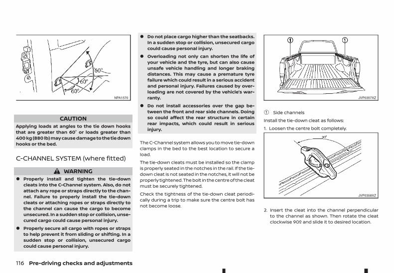
CAUTIONApplying loads at angles to the tie down hooksthat are greater than 60° or loads greater than400 kg (880 lb) may cause damage to the tie downhooks or the bed.
C-CHANNEL SYSTEM (where fitted)
WARNING• Properly install and tighten the tie-down
cleats into the C-Channel system. Also, do notattach any rope or straps directly to the chan-nel. Failure to properly install the tie-downcleats or attaching ropes or straps directly tothe channel can cause the cargo to becomeunsecured. In a sudden stop or collision, unse-cured cargo could cause personal injury.
• Properly secure all cargo with ropes or strapsto help prevent it from sliding or shifting. In asudden stop or collision, unsecured cargocould cause personal injury.
• Do not place cargo higher than the seatbacks.In a sudden stop or collision, unsecured cargocould cause personal injury.
• Overloading not only can shorten the life ofyour vehicle and the tyre, but can also causeunsafe vehicle handling and longer brakingdistances. This may cause a premature tyrefailure which could result in a serious accidentand personal injury. Failures caused by over-loading are not covered by the vehicle’s war-ranty.
• Do not install accessories over the gap be-tween the front and rear side channels. Doingso could affect the rear structure in certainrear impacts, which could result in seriousinjury.
The C-Channel system allows you to move tie-downclamps in the bed to the best location to secure aload.
The tie-down cleats must be installed so the clampis properly seated in the notches in the rail. If the tie-down cleat is not seated in the notches, it will not beproperly tightened.The bolt in the centre of the cleatmust be securely tightened.
Check the tightness of the tie-down cleat periodi-cally during a trip to make sure the centre bolt hasnot become loose.
➀ Side channels
Install the tie-down cleat as follows:
1. Loosen the centre bolt completely.
2. Insert the cleat into the channel perpendicularto the channel as shown. Then rotate the cleatclockwise 90º and slide it to desired location.
NPA1570 JVP0357XZ
JVP0358XZ
116 Pre-driving checks and adjustments
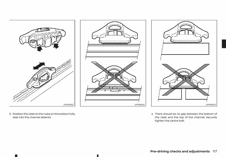
3. Position the cleat so the nubs on the bottom fullyseat into the channel detents.
4. There should be no gap between the bottom ofthe cleat and the top of the channel. Securelytighten the centre bolt.
JVP0359XZ JVP0360XZ JVP0362XZ
Pre-driving checks and adjustments 117
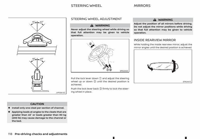
CAUTION• Install only one cleat per section of channel.
• Applying loads at angles to the cleats that aregreater than 45° or loads greater than 90 kg(200 lb) may cause damage to the channel orthe bed.
STEERING WHEEL ADJUSTMENT
WARNINGNever adjust the steering wheel while driving sothat full attention may be given to vehicleoperation.
Pull the lock lever down ➀ and adjust the steeringwheel up or down ➁ until the desired position isachieved.
Push the lock lever back ➂ firmly to lock the steer-ing wheel in place.
WARNINGAdjust the position of all mirrors before driving.Do not adjust the mirror positions while drivingso that full attention may be given to vehicleoperation.
INSIDE REARVIEW MIRRORWhile holding the inside rearview mirror, adjust themirror angles until the desired position is achieved.
JVP0361XZ
SPA2225Z
SPA2447Z
STEERING WHEEL MIRRORS
118 Pre-driving checks and adjustments
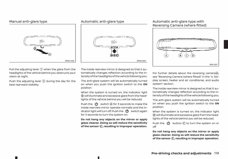
Manual anti-glare type
Pull the adjusting lever ➀ when the glare from theheadlights of the vehicle behind you obstructs yourvision at night.
Push the adjusting lever ➁ during the day for thebest rearward visibility.
Automatic anti-glare type
The inside rearview mirror is designed so that it au-tomatically changes reflection according to the in-tensity of the headlights of the vehicle following you.
The anti-glare system will be automatically turnedon when you push the ignition switch to the ONposition.
When the system is turned on, the indicator lightjB will illuminate and excessive glare from the head-lights of the vehicle behind you will be reduced.
Push the switchjA for 3 seconds to make theinside rearview mirror operate normally and the in-dicator light will turn off. Push the switch againfor 3 seconds to turn the system on.
Do not hang any objects on the mirror or applyglass cleaner. Doing so will reduce the sensitivityof the sensorjC , resulting in improper operation.
Automatic anti-glare type withReversing Camera (where fitted)
For further details about the reversing camerajA ,see “Reversing Camera (where fitted)” in the “4. Dis-play screen, heater and air conditioner, and audiosystem” section.
The inside rearview mirror is designed so that it au-tomatically changes reflection according to the in-tensity of the headlights of the vehicle following you.
The anti-glare system will be automatically turnedon when you push the ignition switch to the ONposition.
When the system is turned on, the indicator lightjB will illuminate and excessive glare from the head-lights of the vehicle behind you will be reduced.
Push the buttonjC to turn the system on oroff
Do not hang any objects on the mirror or applyglass cleaner. Doing so will reduce the sensitivityof the sensorjC , resulting in improper operation.
SPA2143Z SPA2162Z
NPA1097
Pre-driving checks and adjustments 119
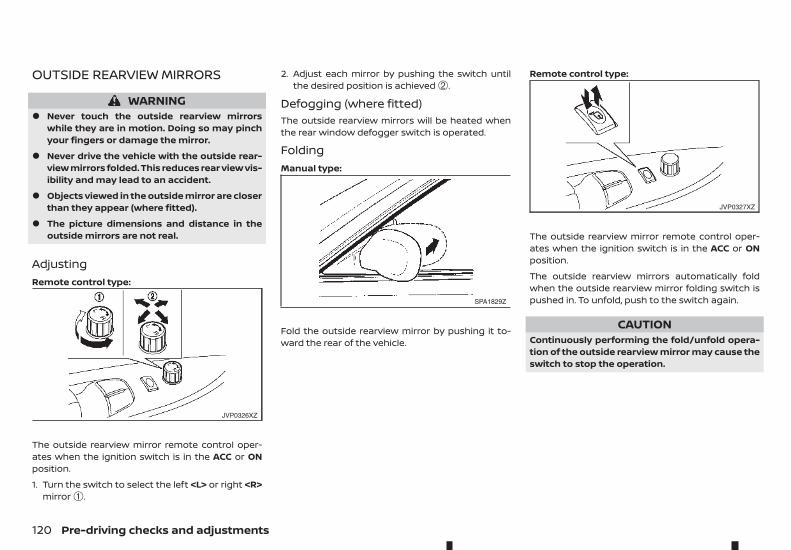
OUTSIDE REARVIEW MIRRORS
WARNING• Never touch the outside rearview mirrors
while they are in motion. Doing so may pinchyour fingers or damage the mirror.
• Never drive the vehicle with the outside rear-view mirrors folded. This reduces rear view vis-ibility and may lead to an accident.
• Objects viewed in the outside mirror are closerthan they appear (where fitted).
• The picture dimensions and distance in theoutside mirrors are not real.
AdjustingRemote control type:
The outside rearview mirror remote control oper-ates when the ignition switch is in the ACC or ONposition.
1. Turn the switch to select the left <L> or right <R>mirror ➀.
2. Adjust each mirror by pushing the switch untilthe desired position is achieved ➁.
Defogging (where fitted)The outside rearview mirrors will be heated whenthe rear window defogger switch is operated.
FoldingManual type:
Fold the outside rearview mirror by pushing it to-ward the rear of the vehicle.
Remote control type:
The outside rearview mirror remote control oper-ates when the ignition switch is in the ACC or ONposition.
The outside rearview mirrors automatically foldwhen the outside rearview mirror folding switch ispushed in. To unfold, push to the switch again.
CAUTIONContinuously performing the fold/unfold opera-tion of the outside rearview mirror may cause theswitch to stop the operation.
JVP0326XZ
SPA1829Z
JVP0327XZ
120 Pre-driving checks and adjustments
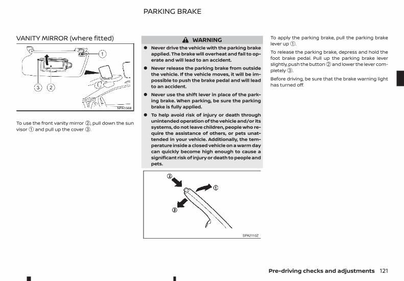
VANITY MIRROR (where fitted)
To use the front vanity mirror ➁, pull down the sunvisor ➀ and pull up the cover ➂.
WARNING• Never drive the vehicle with the parking brake
applied. The brake will overheat and fail to op-erate and will lead to an accident.
• Never release the parking brake from outsidethe vehicle. If the vehicle moves, it will be im-possible to push the brake pedal and will leadto an accident.
• Never use the shift lever in place of the park-ing brake. When parking, be sure the parkingbrake is fully applied.
• To help avoid risk of injury or death throughunintended operation of the vehicle and/or itssystems, do not leave children, people who re-quire the assistance of others, or pets unat-tended in your vehicle. Additionally, the tem-perature inside a closed vehicle on a warm daycan quickly become high enough to cause asignificant risk of injury or death to people andpets.
To apply the parking brake, pull the parking brakelever up ➀.
To release the parking brake, depress and hold thefoot brake pedal. Pull up the parking brake leverslightly, push the button ➁ and lower the lever com-pletely ➂.
Before driving, be sure that the brake warning lighthas turned off.
NPA1568
SPA2110Z
PARKING BRAKE
Pre-driving checks and adjustments 121

NOTE
122 Pre-driving checks and adjustments
4 Display screen, heater and airconditioner, and audio systemDisplay screen, heater and airconditioner, and audio system
Safety precautions...................................................................................... 124Reversing Camera (where fitted) ..................................................... 124
How to read the displayed lines ............................................... 125Difference between predictive and actualdistances.................................................................................................... 125Rear-view monitor setting............................................................ 127Operating tips ........................................................................................ 127
Intelligent Around-View Monitor (where fitted) .................... 127Operation................................................................................................... 130Guide lines................................................................................................. 131Difference between predictive and actualdistances.................................................................................................... 133How to adjust the screen view.................................................. 136Operating tips ........................................................................................ 136
Vents...................................................................................................................... 136Centre vents ............................................................................................ 136Side vents .................................................................................................. 137Rear vents (where fitted)................................................................ 137
Heater and air conditioner.................................................................... 137Operating tips (models with automatic airconditioner).............................................................................................. 138Manual air conditioner and heater (Type A).................... 139Manual air conditioner and heater (Type B).................... 141Automatic air conditioner............................................................. 144Servicing air conditioner ................................................................ 146
Audio system (where fitted)................................................................. 146Audio operation precautions...................................................... 146Antenna ...................................................................................................... 150USB (Universal Serial Bus) connection port..................... 150AUX (Auxiliary) input jack ............................................................... 151CD/USB memory care and cleaning ..................................... 151
FM AM radio with compact disc (CD) player(Type A) ................................................................................................................ 152
Audio main operation....................................................................... 153Radio operation .................................................................................... 153SETUP button ......................................................................................... 154Compact Disc (CD) operation..................................................... 156AUX (Auxiliary) socket ....................................................................... 157USB (Universal Serial Bus) connection port(where fitted)........................................................................................... 157iPod player operation (where fitted) ..................................... 159Bluetooth® operation ....................................................................... 160
FM-AM radio with compact disc (CD) player Type B.......... 166Audio main operation....................................................................... 167Radio operation .................................................................................... 167SETUP button ......................................................................................... 168Compact Disc (CD) operation..................................................... 170AUX socket................................................................................................ 172USB (Universal Serial Bus) Connection Port .................... 172iPod® player operation (where fitted)................................... 173Bluetooth® operation ....................................................................... 174
Touchscreen Navigation (where fitted)....................................... 180Apple CarPlay and Android Auto (where fitted).................... 180Steering wheel switch for audio control (wherefitted)..................................................................................................................... 180
Audio control........................................................................................... 180Phone control buttons .................................................................... 181
Bluetooth® Hands-Free Phone System (withoutnavigation system and colour display) ....................................... 182
Bluetooth® mobile phone feature........................................... 182Hands-free telephone control ................................................... 184Steering wheel switches (where fitted) .............................. 186
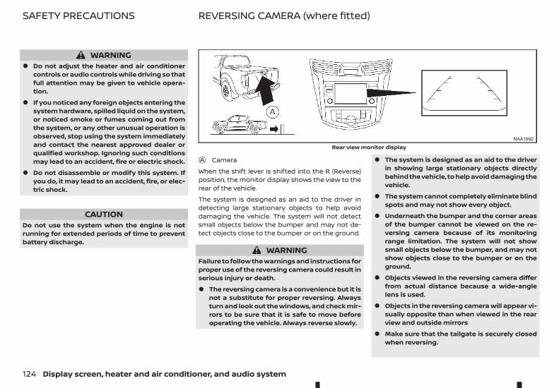
WARNING• Do not adjust the heater and air conditioner
controls or audio controls while driving so thatfull attention may be given to vehicle opera-tion.
• If you noticed any foreign objects entering thesystem hardware, spilled liquid on the system,or noticed smoke or fumes coming out fromthe system, or any other unusual operation isobserved, stop using the system immediatelyand contact the nearest approved dealer orqualified workshop. Ignoring such conditionsmay lead to an accident, fire or electric shock.
• Do not disassemble or modify this system. Ifyou do, it may lead to an accident, fire, or elec-tric shock.
CAUTIONDo not use the system when the engine is notrunning for extended periods of time to preventbattery discharge.
jA Camera
When the shift lever is shifted into the R (Reverse)position, the monitor display shows the view to therear of the vehicle.
The system is designed as an aid to the driver indetecting large stationary objects to help avoiddamaging the vehicle. The system will not detectsmall objects below the bumper and may not de-tect objects close to the bumper or on the ground.
WARNINGFailure to follow the warnings and instructions forproper use of the reversing camera could result inserious injury or death.
• The reversing camera is a convenience but it isnot a substitute for proper reversing. Alwaysturn and look out the windows, and check mir-rors to be sure that it is safe to move beforeoperating the vehicle. Always reverse slowly.
• The system is designed as an aid to the driverin showing large stationary objects directlybehind the vehicle, to help avoid damaging thevehicle.
• The system cannot completely eliminate blindspots and may not show every object.
• Underneath the bumper and the corner areasof the bumper cannot be viewed on the re-versing camera because of its monitoringrange limitation. The system will not showsmall objects below the bumper, and may notshow objects close to the bumper or on theground.
• Objects viewed in the reversing camera differfrom actual distance because a wide-anglelens is used.
• Objects in the reversing camera will appear vi-sually opposite than when viewed in the rearview and outside mirrors
• Make sure that the tailgate is securely closedwhen reversing.
NAA1992
Rear view monitor display
SAFETY PRECAUTIONS REVERSING CAMERA (where fitted)
124 Display screen, heater and air conditioner, and audio system
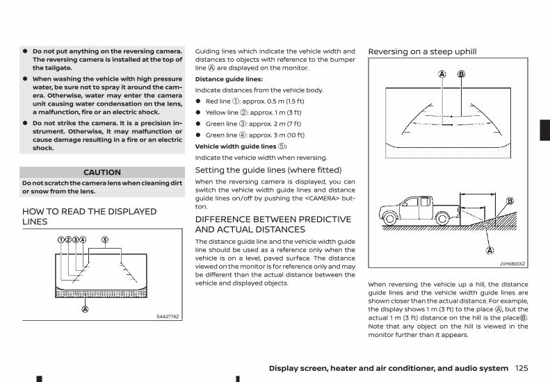
• Do not put anything on the reversing camera.The reversing camera is installed at the top ofthe tailgate.
• When washing the vehicle with high pressurewater, be sure not to spray it around the cam-era. Otherwise, water may enter the cameraunit causing water condensation on the lens,a malfunction, fire or an electric shock.
• Do not strike the camera. It is a precision in-strument. Otherwise, it may malfunction orcause damage resulting in a fire or an electricshock.
CAUTIONDo not scratch the camera lens when cleaning dirtor snow from the lens.
HOW TO READ THE DISPLAYEDLINES
Guiding lines which indicate the vehicle width anddistances to objects with reference to the bumperlinejA are displayed on the monitor.
Distance guide lines:
Indicate distances from the vehicle body.
• Red line ➀: approx. 0.5 m (1.5 ft)
• Yellow line ➁: approx. 1 m (3 ft)
• Green line ➂: approx. 2 m (7 ft)
• Green line ➃: approx. 3 m (10 ft)
Vehicle width guide lines ➄:
Indicate the vehicle width when reversing.
Setting the guide lines (where fitted)When the reversing camera is displayed, you canswitch the vehicle width guide lines and distanceguide lines on/off by pushing the <CAMERA> but-ton.
DIFFERENCE BETWEEN PREDICTIVEAND ACTUAL DISTANCESThe distance guide line and the vehicle width guideline should be used as a reference only when thevehicle is on a level, paved surface. The distanceviewed on the monitor is for reference only and maybe different than the actual distance between thevehicle and displayed objects.
Reversing on a steep uphill
When reversing the vehicle up a hill, the distanceguide lines and the vehicle width guide lines areshown closer than the actual distance. For example,the display shows 1 m (3 ft) to the placejA , but theactual 1 m (3 ft) distance on the hill is the placejB .Note that any object on the hill is viewed in themonitor further than it appears.
SAA2776Z
JVH0893XZ
Display screen, heater and air conditioner, and audio system 125
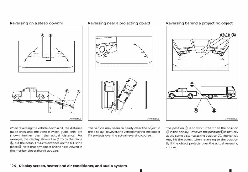
Reversing on a steep downhill
When reversing the vehicle down a hill, the distanceguide lines and the vehicle width guide lines areshown further than the actual distance. Forexample, the display shows 1 m (3 ft) to the placejA , but the actual 1 m (3 ft) distance on the hill is theplacejB . Note that any object on the hill is viewed inthe monitor closer than it appears.
Reversing near a projecting object
The vehicle may seem to nearly clear the object inthe display. However, the vehicle may hit the objectif it projects over the actual reversing course.
Reversing behind a projecting object
The positionjC is shown further than the positionjB in the display. However, the positionjC is actuallyat the same distance as the positionjA . The vehiclemay hit the object when reversing to the positionjA if the object projects over the actual reversingcourse.
JVH0894XZ JVH0896XZ JVH0895XZ
126 Display screen, heater and air conditioner, and audio system
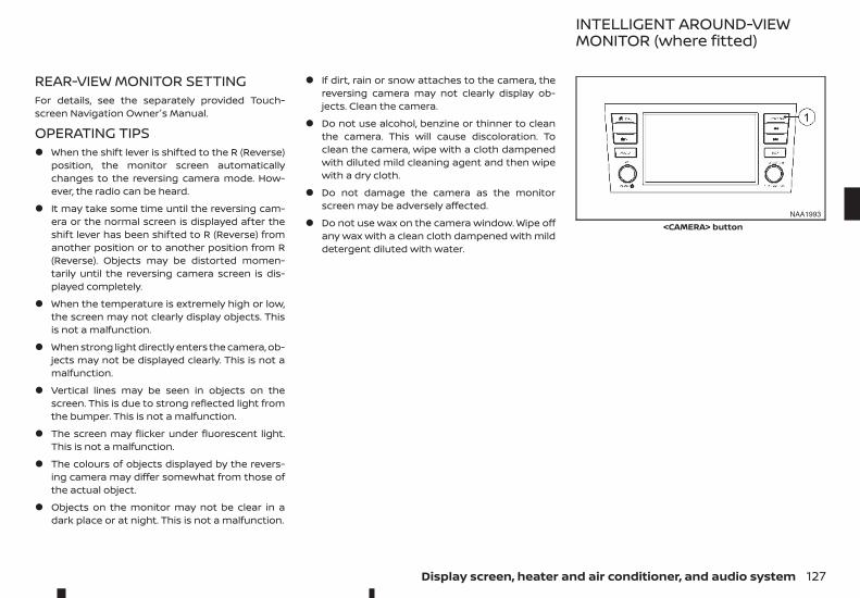
REAR-VIEW MONITOR SETTINGFor details, see the separately provided Touch-screen Navigation Owner's Manual.
OPERATING TIPS• When the shift lever is shifted to the R (Reverse)
position, the monitor screen automaticallychanges to the reversing camera mode. How-ever, the radio can be heard.
• It may take some time until the reversing cam-era or the normal screen is displayed after theshift lever has been shifted to R (Reverse) fromanother position or to another position from R(Reverse). Objects may be distorted momen-tarily until the reversing camera screen is dis-played completely.
• When the temperature is extremely high or low,the screen may not clearly display objects. Thisis not a malfunction.
• When strong light directly enters the camera, ob-jects may not be displayed clearly. This is not amalfunction.
• Vertical lines may be seen in objects on thescreen. This is due to strong reflected light fromthe bumper. This is not a malfunction.
• The screen may flicker under fluorescent light.This is not a malfunction.
• The colours of objects displayed by the revers-ing camera may differ somewhat from those ofthe actual object.
• Objects on the monitor may not be clear in adark place or at night. This is not a malfunction.
• If dirt, rain or snow attaches to the camera, thereversing camera may not clearly display ob-jects. Clean the camera.
• Do not use alcohol, benzine or thinner to cleanthe camera. This will cause discoloration. Toclean the camera, wipe with a cloth dampenedwith diluted mild cleaning agent and then wipewith a dry cloth.
• Do not damage the camera as the monitorscreen may be adversely affected.
• Do not use wax on the camera window. Wipe offany wax with a clean cloth dampened with milddetergent diluted with water.
NAA1993
<CAMERA> button
INTELLIGENT AROUND-VIEWMONITOR (where fitted)
Display screen, heater and air conditioner, and audio system 127
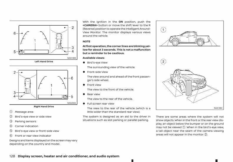
➀ Message area
➁ Bird's-eye view or side view
➂ Parking sensors
➃ Corner indication
➄ Bird's-eye view or front-side view
➅ Front or rear view indicator
Designs and items displayed on the screen may varydepending on the country and model.
With the ignition in the ON position, push the<CAMERA> button or move the shift lever to the R(Reverse) position to operate the Intelligent Around-View Monitor. The monitor displays various viewsaround the vehicle.
NOTE
At first operation, the corner lines are blinking yel-low for about 3 seconds. This is not a malfunctionbut a reminder to be cautious.
Available views:
• Bird's-eye View
The surrounding view of the vehicle.
• Front-side View
The view around and ahead of the front passen-ger’s side wheel.
• Front view
The view to the front of the vehicle.
• Rear view
The view to the rear of the vehicle.
• Full screen rear view
The view to the rear of the vehicle (which is alittle wider than the standard rear view).
The system is designed as an aid to the driver insituations such as slot parking or parallel parking.
There are some areas where the system will notshow objects. When in the front or the rear view dis-play, an object below the bumper or on the groundmay not be viewed ➀. When in the bird's-eye view,a tall object near the seam of the camera viewingareas will not appear in the monitor ➁.
NAA1999
Left Hand Drive
NAA2000
Right Hand DriveNAA1864
128 Display screen, heater and air conditioner, and audio system
WARNING• The Intelligent Around-View Monitor is
intended for day time use. Do not use the sys-tem in bad light conditions.
• The Intelligent Around-View Monitor is a con-venience feature. It is not a substitute forproper vehicle operation because it has areaswhere objects cannot be viewed. The four cor-ners of the vehicle in particular, are blind spotswhere objects do not appear in the bird's-eye,front or rear views. Always look out the win-dows and check to be sure that it is safe tomove. The driver is always responsible forsafety during parking and other manoeuvres.
• Do not use the Intelligent Around-View Moni-tor with the outside mirror in the stored posi-tion, and make sure that the back door is se-curely closed when operating the vehicle us-ing the Intelligent Around-View Monitor.
• The distance between objects viewed on theIntelligent Around-View Monitor differs fromthe actual distance.
• The cameras are installed on the front grille,the outside mirrors and above the rear num-ber plate. Do not put anything on the cameras.
• When washing the vehicle with high-pressurewater, be sure not to spray it around the cam-eras. Otherwise, water may enter the cameraunit causing water condensation on the lens,a malfunction, fire or an electric shock.
• Do not strike the cameras. They are precisioninstruments. Doing so could cause a malfunc-tion or cause damage resulting in a fire or anelectric shock.
CAUTIONDo not scratch the lens when cleaning dirt orsnow from the front of the camera.
Display screen, heater and air conditioner, and audio system 129
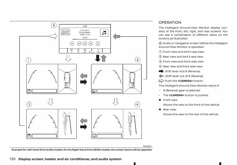
OPERATIONThe Intelligent Around-View Monitor display con-sists of the front, left, right, and rear screens. Youcan see a combination of different views on thescreens as illustrated.jA : Audio or navigation screen before the IntelligentAround-View Monitor is operated.
➀: Front view and bird's-eye view
➁: Rear view and bird's-eye view
➂: Front view and front side view
➃: Rear view and front side view
: Shift lever into R (Reverse)
: Shift lever out of R (Reverse)
: Push the <CAMERA> button
The Intelligent Around-View Monitor starts if:
– R (Reverse) gear is selected.
– The <CAMERA> button is pushed.
• Front view
Shows the view to the front of the vehicle.
• Rear view
Shows the view to the rear of the vehicle.
NAA2001
Example for Left-Hand Drive (LHD) models, for the Right-Hand Drive (RHD) models, the screen layout will be opposite.
130 Display screen, heater and air conditioner, and audio system
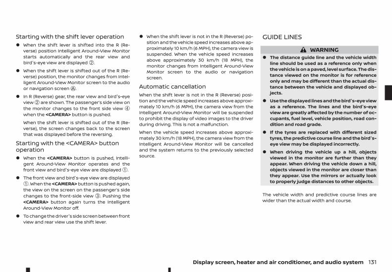
Starting with the shift lever operation• When the shift lever is shifted into the R (Re-
verse) position Intelligent Around-View Monitorstarts automatically and the rear view andbird's-eye view are displayed ➁.
• When the shift lever is shifted out of the R (Re-verse) position, the monitor changes from Intel-ligent Around-View Monitor screen to the audioor navigation screenjA .
• In R (Reverse) gear, the rear view and bird's-eyeview ➁ are shown. The passenger’s side view onthe monitor changes to the front side view ➃when the <CAMERA> button is pushed.
When the shift lever is shifted out of the R (Re-verse), the screen changes back to the screenthat was displayed before the reversing.
Starting with the <CAMERA> buttonoperation• When the <CAMERA> button is pushed, Intelli-
gent Around-View Monitor operates and thefront view and bird's-eye view are displayed ➀.
• The front view and bird's-eye view are displayed➀. When the <CAMERA> button is pushed again,the view on the screen on the passenger’s sidechanges to the front-side view ➂. Pushing the<CAMERA> button again turns the IntelligentAround-View Monitor off.
• To change the driver's side screen between frontview and rear view use the shift lever.
• When the shift lever is not in the R (Reverse) po-sition and the vehicle speed increases above ap-proximately 10 km/h (6 MPH), the camera view issuspended. When the vehicle speed increasesabove approximately 30 km/h (18 MPH), themonitor changes from Intelligent Around-ViewMonitor screen to the audio or navigationscreen.
Automatic cancellationWhen the shift lever is not in the R (Reverse) posi-tion and the vehicle speed increases above approxi-mately 10 km/h (6 MPH), the camera view from theIntelligent Around-View Monitor will be suspendedto prohibit the display of video images to the driverduring driving. This is not a malfunction.
When the vehicle speed increases above approxi-mately 30 km/h (18 MPH), the camera view from theIntelligent Around-View Monitor will be cancelledand the system returns to the previously selectedsource.
GUIDE LINES
WARNING• The distance guide line and the vehicle width
line should be used as a reference only whenthe vehicle is on a paved, level surface. The dis-tance viewed on the monitor is for referenceonly and may be different than the actual dis-tance between the vehicle and displayed ob-jects.
• Use the displayed lines and the bird's-eye viewas a reference. The lines and the bird's-eyeview are greatly affected by the number of oc-cupants, fuel level, vehicle position, road con-dition and road grade.
• If the tyres are replaced with different sizedtyres, the predictive course line and the bird's-eye view may be displayed incorrectly.
• When driving the vehicle up a hill, objectsviewed in the monitor are further than theyappear. When driving the vehicle down a hill,objects viewed in the monitor are closer thanthey appear. Use the mirrors or actually lookto properly judge distances to other objects.
The vehicle width and predictive course lines arewider than the actual width and course.
Display screen, heater and air conditioner, and audio system 131
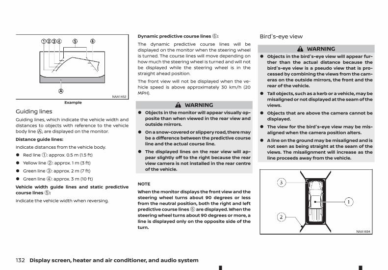
Guiding linesGuiding lines, which indicate the vehicle width anddistances to objects with reference to the vehiclebody linejA , are displayed on the monitor.
Distance guide lines:
Indicate distances from the vehicle body.
• Red line ➀: approx. 0.5 m (1.5 ft)
• Yellow line ➁: approx. 1 m (3 ft)
• Green line ➂: approx. 2 m (7 ft)
• Green line ➃: approx. 3 m (10 ft)
Vehicle width guide lines and static predictivecourse lines ➄:
Indicate the vehicle width when reversing.
Dynamic predictive course lines ➅:
The dynamic predictive course lines will bedisplayed on the monitor when the steering wheelis turned. The course lines will move depending onhow much the steering wheel is turned and will notbe displayed while the steering wheel is in thestraight ahead position.
The front view will not be displayed when the ve-hicle speed is above approximately 30 km/h (20MPH).
WARNING• Objects in the monitor will appear visually op-
posite than when viewed in the rear view andoutside mirrors.
• On a snow-covered or slippery road, there maybe a difference between the predictive courseline and the actual course line.
• The displayed lines on the rear view will ap-pear slightly off to the right because the rearview camera is not installed in the rear centreof the vehicle.
NOTE
When the monitor displays the front view and thesteering wheel turns about 90 degrees or lessfrom the neutral position, both the right and leftpredictive course lines ➅ are displayed. When thesteering wheel turns about 90 degrees or more, aline is displayed only on the opposite side of theturn.
Bird's-eye view
WARNING• Objects in the bird's-eye view will appear fur-
ther than the actual distance because thebird's-eye view is a pseudo view that is pro-cessed by combining the views from the cam-eras on the outside mirrors, the front and therear of the vehicle.
• Tall objects, such as a kerb or a vehicle, may bemisaligned or not displayed at the seam of theviews.
• Objects that are above the camera cannot bedisplayed.
• The view for the bird's-eye view may be mis-aligned when the camera position alters.
• A line on the ground may be misaligned and isnot seen as being straight at the seam of theviews. The misalignment will increase as theline proceeds away from the vehicle.
NAA1452
Example
NAA1694
132 Display screen, heater and air conditioner, and audio system
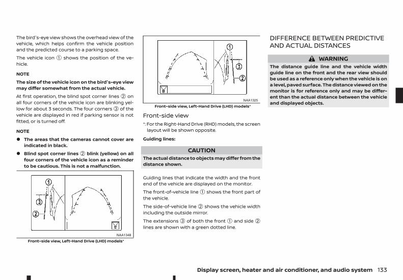
The bird's-eye view shows the overhead view of thevehicle, which helps confirm the vehicle positionand the predicted course to a parking space.
The vehicle icon ➀ shows the position of the ve-hicle.
NOTE
The size of the vehicle icon on the bird's-eye viewmay differ somewhat from the actual vehicle.
At first operation, the blind spot corner lines ➁ onall four corners of the vehicle icon are blinking yel-low for about 3 seconds. The four corners ➂ of thevehicle are displayed in red if parking sensor is notfitted, or is turned off.
NOTE
• The areas that the cameras cannot cover areindicated in black.
• Blind spot corner lines ➁ blink (yellow) on allfour corners of the vehicle icon as a reminderto be cautious. This is not a malfunction.
Front-side view*: For the Right-Hand Drive (RHD) models, the screen
layout will be shown opposite.
Guiding lines:
CAUTIONThe actual distance to objects may differ from thedistance shown.
Guiding lines that indicate the width and the frontend of the vehicle are displayed on the monitor.
The front-of-vehicle line ➀ shows the front part ofthe vehicle.
The side-of-vehicle line ➁ shows the vehicle widthincluding the outside mirror.
The extensions ➂ of both the front ➀ and side ➁lines are shown with a green dotted line.
DIFFERENCE BETWEEN PREDICTIVEAND ACTUAL DISTANCES
WARNINGThe distance guide line and the vehicle widthguide line on the front and the rear view shouldbe used as a reference only when the vehicle is ona level, paved surface. The distance viewed on themonitor is for reference only and may be differ-ent than the actual distance between the vehicleand displayed objects.
NAA1348
Front–side view, Left-Hand Drive (LHD) models*
NAA1325
Front–side view, Left-Hand Drive (LHD) models*
Display screen, heater and air conditioner, and audio system 133
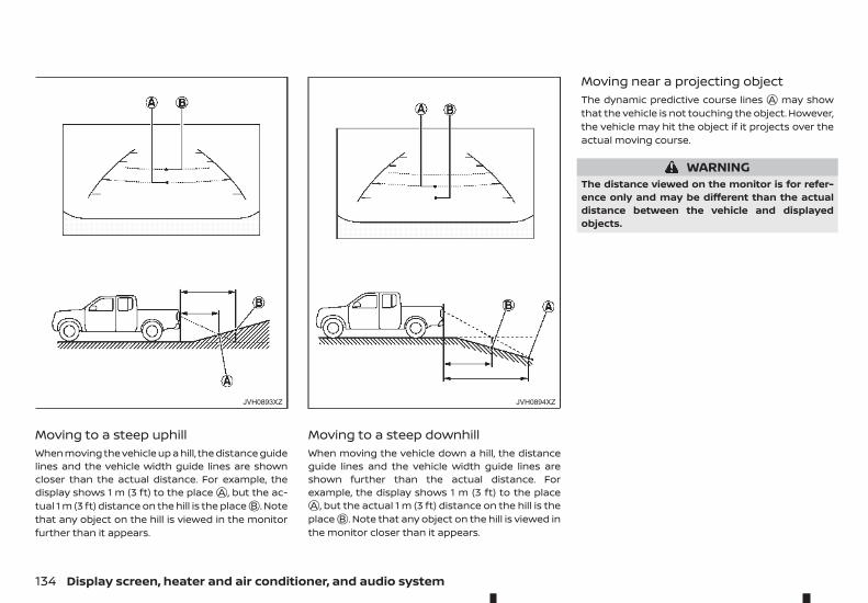
Moving to a steep uphillWhen moving the vehicle up a hill, the distance guidelines and the vehicle width guide lines are showncloser than the actual distance. For example, thedisplay shows 1 m (3 ft) to the placejA , but the ac-tual 1 m (3 ft) distance on the hill is the placejB . Notethat any object on the hill is viewed in the monitorfurther than it appears.
Moving to a steep downhillWhen moving the vehicle down a hill, the distanceguide lines and the vehicle width guide lines areshown further than the actual distance. Forexample, the display shows 1 m (3 ft) to the placejA , but the actual 1 m (3 ft) distance on the hill is theplacejB . Note that any object on the hill is viewed inthe monitor closer than it appears.
Moving near a projecting objectThe dynamic predictive course lines jA may showthat the vehicle is not touching the object. However,the vehicle may hit the object if it projects over theactual moving course.
WARNINGThe distance viewed on the monitor is for refer-ence only and may be different than the actualdistance between the vehicle and displayedobjects.
JVH0893XZ JVH0894XZ
134 Display screen, heater and air conditioner, and audio system
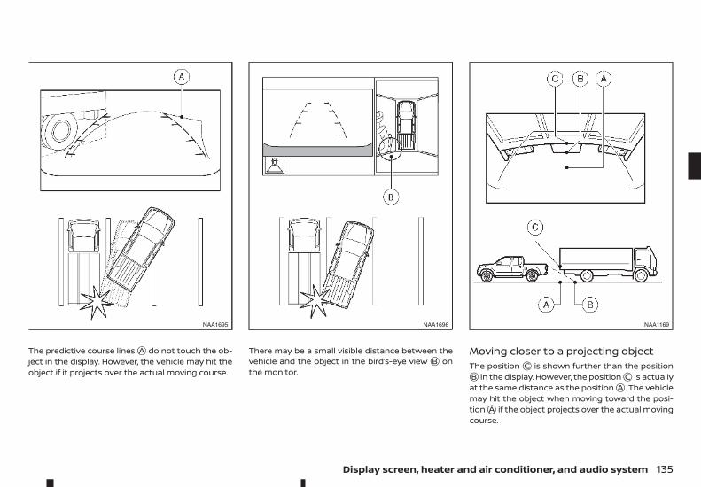
The predictive course linesjA do not touch the ob-ject in the display. However, the vehicle may hit theobject if it projects over the actual moving course.
There may be a small visible distance between thevehicle and the object in the bird’s-eye viewjB onthe monitor.
Moving closer to a projecting objectThe positionjC is shown further than the positionjB in the display. However, the positionjC is actuallyat the same distance as the positionjA . The vehiclemay hit the object when moving toward the posi-tionjA if the object projects over the actual movingcourse.
NAA1695 NAA1696 NAA1169
Display screen, heater and air conditioner, and audio system 135
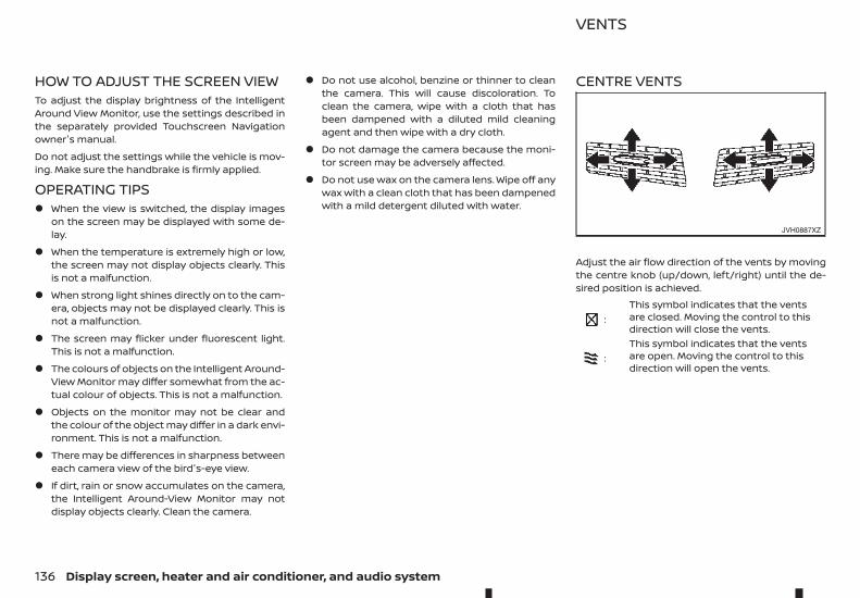
HOW TO ADJUST THE SCREEN VIEWTo adjust the display brightness of the IntelligentAround View Monitor, use the settings described inthe separately provided Touchscreen Navigationowner's manual.
Do not adjust the settings while the vehicle is mov-ing. Make sure the handbrake is firmly applied.
OPERATING TIPS• When the view is switched, the display images
on the screen may be displayed with some de-lay.
• When the temperature is extremely high or low,the screen may not display objects clearly. Thisis not a malfunction.
• When strong light shines directly on to the cam-era, objects may not be displayed clearly. This isnot a malfunction.
• The screen may flicker under fluorescent light.This is not a malfunction.
• The colours of objects on the Intelligent Around-View Monitor may differ somewhat from the ac-tual colour of objects. This is not a malfunction.
• Objects on the monitor may not be clear andthe colour of the object may differ in a dark envi-ronment. This is not a malfunction.
• There may be differences in sharpness betweeneach camera view of the bird's-eye view.
• If dirt, rain or snow accumulates on the camera,the Intelligent Around-View Monitor may notdisplay objects clearly. Clean the camera.
• Do not use alcohol, benzine or thinner to cleanthe camera. This will cause discoloration. Toclean the camera, wipe with a cloth that hasbeen dampened with a diluted mild cleaningagent and then wipe with a dry cloth.
• Do not damage the camera because the moni-tor screen may be adversely affected.
• Do not use wax on the camera lens. Wipe off anywax with a clean cloth that has been dampenedwith a mild detergent diluted with water.
CENTRE VENTS
Adjust the air flow direction of the vents by movingthe centre knob (up/down, left/right) until the de-sired position is achieved.
m:This symbol indicates that the ventsare closed. Moving the control to thisdirection will close the vents.
m:This symbol indicates that the ventsare open. Moving the control to thisdirection will open the vents.
JVH0887XZ
VENTS
136 Display screen, heater and air conditioner, and audio system
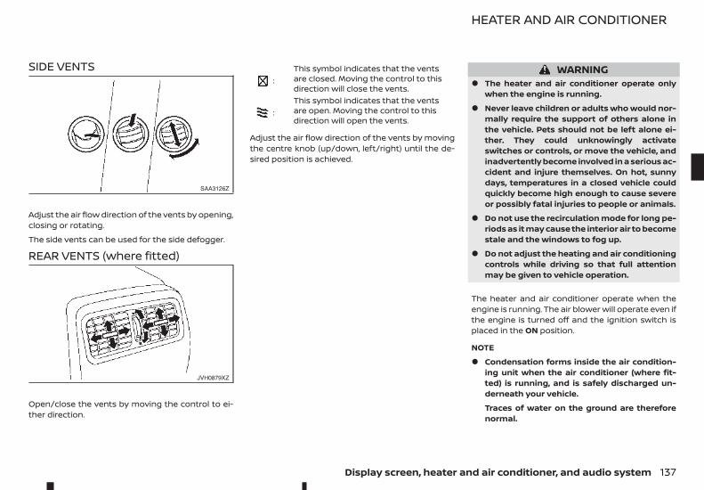
SIDE VENTS
Adjust the air flow direction of the vents by opening,closing or rotating.
The side vents can be used for the side defogger.
REAR VENTS (where fitted)
Open/close the vents by moving the control to ei-ther direction.
m:This symbol indicates that the ventsare closed. Moving the control to thisdirection will close the vents.
m:This symbol indicates that the ventsare open. Moving the control to thisdirection will open the vents.
Adjust the air flow direction of the vents by movingthe centre knob (up/down, left/right) until the de-sired position is achieved.
WARNING• The heater and air conditioner operate only
when the engine is running.
• Never leave children or adults who would nor-mally require the support of others alone inthe vehicle. Pets should not be left alone ei-ther. They could unknowingly activateswitches or controls, or move the vehicle, andinadvertently become involved in a serious ac-cident and injure themselves. On hot, sunnydays, temperatures in a closed vehicle couldquickly become high enough to cause severeor possibly fatal injuries to people or animals.
• Do not use the recirculation mode for long pe-riods as it may cause the interior air to becomestale and the windows to fog up.
• Do not adjust the heating and air conditioningcontrols while driving so that full attentionmay be given to vehicle operation.
The heater and air conditioner operate when theengine is running. The air blower will operate even ifthe engine is turned off and the ignition switch isplaced in the ON position.
NOTE
• Condensation forms inside the air condition-ing unit when the air conditioner (where fit-ted) is running, and is safely discharged un-derneath your vehicle.
Traces of water on the ground are thereforenormal.
SAA3126Z
JVH0879XZ
HEATER AND AIR CONDITIONER
Display screen, heater and air conditioner, and audio system 137
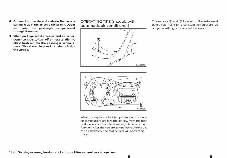
• Odours from inside and outside the vehiclecan build up in the air conditioner unit. Odourcan enter the passenger compartmentthrough the vents.
• When parking, set the heater and air condi-tioner controls to turn off air recirculation toallow fresh air into the passenger compart-ment. This should help reduce odours insidethe vehicle.
OPERATING TIPS (models withautomatic air conditioner)
When the engine coolant temperature and outsideair temperature are low, the air flow from the footoutlets may not operate. However, this is not a mal-function. After the coolant temperature warms up,the air flow from the foot outlets will operate nor-mally.
The sensors jA and jB , located on the instrumentpanel, help maintain a constant temperature. Donot put anything on or around the sensors.
SAA2324Z
NAA1865
138 Display screen, heater and air conditioner, and audio system
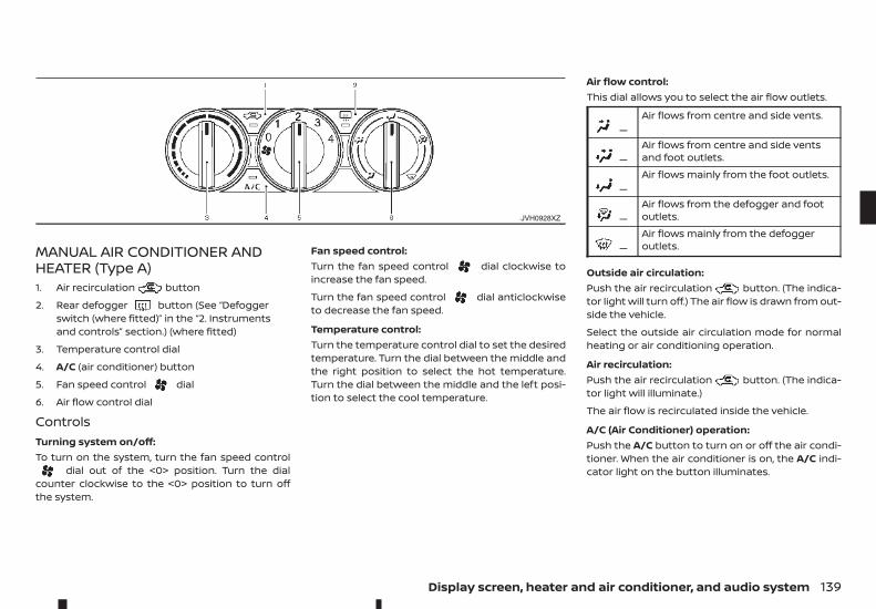
MANUAL AIR CONDITIONER ANDHEATER (Type A)1. Air recirculation button
2. Rear defogger button (See “Defoggerswitch (where fitted)” in the “2. Instrumentsand controls” section.) (where fitted)
3. Temperature control dial
4. A/C (air conditioner) button
5. Fan speed control dial
6. Air flow control dial
ControlsTurning system on/off:To turn on the system, turn the fan speed control
dial out of the <0> position. Turn the dialcounter clockwise to the <0> position to turn offthe system.
Fan speed control:Turn the fan speed control dial clockwise toincrease the fan speed.
Turn the fan speed control dial anticlockwiseto decrease the fan speed.
Temperature control:Turn the temperature control dial to set the desiredtemperature. Turn the dial between the middle andthe right position to select the hot temperature.Turn the dial between the middle and the left posi-tion to select the cool temperature.
Air flow control:This dial allows you to select the air flow outlets.
m —Air flows from centre and side vents.
m —Air flows from centre and side ventsand foot outlets.
m —Air flows mainly from the foot outlets.
m —Air flows from the defogger and footoutlets.
m —Air flows mainly from the defoggeroutlets.
Outside air circulation:Push the air recirculation button. (The indica-tor light will turn off.) The air flow is drawn from out-side the vehicle.
Select the outside air circulation mode for normalheating or air conditioning operation.
Air recirculation:Push the air recirculation button. (The indica-tor light will illuminate.)
The air flow is recirculated inside the vehicle.
A/C (Air Conditioner) operation:Push the A/C button to turn on or off the air condi-tioner. When the air conditioner is on, the A/C indi-cator light on the button illuminates.
JVH0928XZ
Display screen, heater and air conditioner, and audio system 139
Heater operationHeating:This mode is used to direct heated air from the footoutlets.
1. Push the air recirculation button for normalheating. (The indicator light will turn off.)
2. Turn the air flow control dial to the position.
3. Turn the fan speed control dial to the de-sired position.
4. Turn the temperature control dial to the desiredposition between the middle and the hot (right)position.
Ventilation:This mode directs outside air from the side andcentre vents.
1. Push the air recirculation button. (The indi-cator light will turn off.)
2. Turn the air flow control dial to the position.
3. Turn the fan speed control dial to the de-sired position.
4. Turn the temperature control dial to the desiredposition.
Defrosting or defogging:This mode directs the air to the defogger outlets todefrost/defog the windows.
1. Turn the air flow control dial to the position.
2. Push the air recirculation button. (The indi-cator light will turn off.)
3. Turn the fan speed control dial to the de-sired position.
4. Turn the temperature control dial to the desiredposition between the middle and the hot (right)position.
• To remove frost from the windscreen quickly,turn the temperature control dial to the maxi-mum position and the fan speed controldial to the maximum position.
• If it is difficult to defog the windscreen, turn theA/C button on.
Bi-level heating:This mode directs cool air from the side and centrevents and warm air from the foot outlets. When thetemperature control dial is turned to the maximumhot or cool position, the air between the vents andthe foot outlets is the same temperature.
1. Push the air recirculation button. (The indi-cator light will turn off.)
2. Turn the air flow control dial to the position.
3. Turn the fan speed control dial to the de-sired position.
4. Turn the temperature control dial to the desiredposition.
Heating and defogging:This mode heats the interior and defogs the win-dows.
1. Push the air recirculation button. (The indi-cator light will turn off.)
2. Turn the air flow control dial to the position.
3. Turn the fan speed control dial to the desired po-sition.
4. Turn the temperature control dial to the maxi-mum hot (right) position.
Air conditioner operationThe air conditioner system should be operated forapproximately 10 minutes at least once a month.This helps prevent damage to the air conditionersystem due to the lack of lubrication.
Cooling:This mode is used to cool and dehumidify the air.
1. Push the air recirculation button. (The indi-cator light will turn off.)
2. Turn the air flow control dial to the position.
3. Turn the fan speed control dial to the desired po-sition.
4. Push the A/C button on. (The A/C indicator lightwill illuminate.)
5. Turn the temperature control dial to the desiredposition between the middle and the cool (left)position.
A visible mist may be seen coming from the vents inhot, humid conditions as the air is cooled rapidly.This does not indicate a malfunction.
• For quick cooling when the outside temperatureis high, push the air recirculation button.(The indicator light will turn on.) Be sure to re-turn the air recirculation button to turn offfor normal cooling.
Dehumidified heating:This mode is used to heat and dehumidify the air.
1. Push the air recirculation button. (The indi-cator light will turn off.)
2. Turn the air flow control dial to the position.
140 Display screen, heater and air conditioner, and audio system
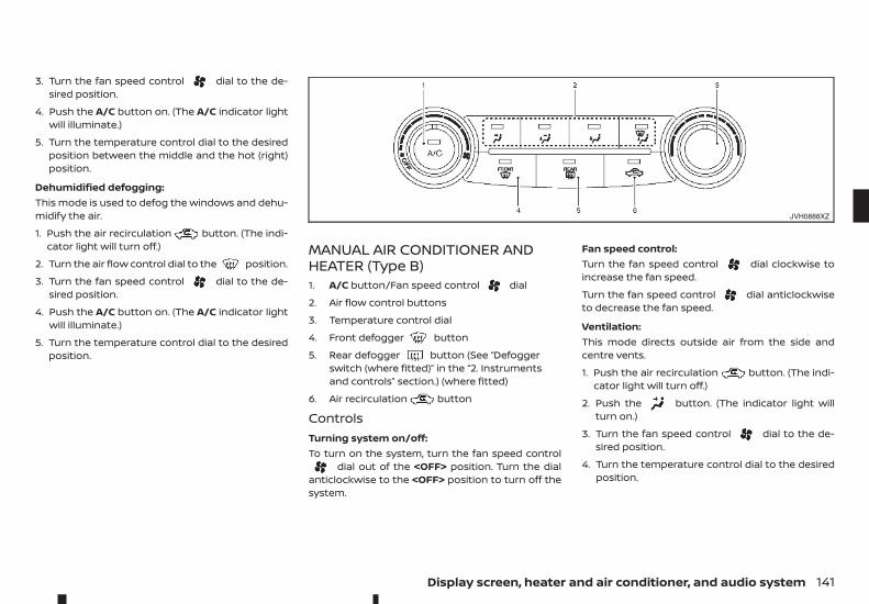
3. Turn the fan speed control dial to the de-sired position.
4. Push the A/C button on. (The A/C indicator lightwill illuminate.)
5. Turn the temperature control dial to the desiredposition between the middle and the hot (right)position.
Dehumidified defogging:This mode is used to defog the windows and dehu-midify the air.
1. Push the air recirculation button. (The indi-cator light will turn off.)
2. Turn the air flow control dial to the position.
3. Turn the fan speed control dial to the de-sired position.
4. Push the A/C button on. (The A/C indicator lightwill illuminate.)
5. Turn the temperature control dial to the desiredposition.
MANUAL AIR CONDITIONER ANDHEATER (Type B)1. A/C button/Fan speed control dial
2. Air flow control buttons
3. Temperature control dial
4. Front defogger button
5. Rear defogger button (See “Defoggerswitch (where fitted)” in the “2. Instrumentsand controls” section.) (where fitted)
6. Air recirculation button
ControlsTurning system on/off:To turn on the system, turn the fan speed control
dial out of the <OFF> position. Turn the dialanticlockwise to the <OFF> position to turn off thesystem.
Fan speed control:Turn the fan speed control dial clockwise toincrease the fan speed.
Turn the fan speed control dial anticlockwiseto decrease the fan speed.
Ventilation:This mode directs outside air from the side andcentre vents.
1. Push the air recirculation button. (The indi-cator light will turn off.)
2. Push the button. (The indicator light willturn on.)
3. Turn the fan speed control dial to the de-sired position.
4. Turn the temperature control dial to the desiredposition.
JVH0888XZ
Display screen, heater and air conditioner, and audio system 141
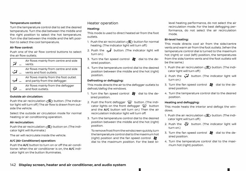
Temperature control:Turn the temperature control dial to set the desiredtemperature. Turn the dial between the middle andthe right position to select the hot temperature.Turn the dial between the middle and the left posi-tion to select the cool temperature.
Air flow control:Push one of the air flow control buttons to selectthe air flow outlets.
m —Air flows mainly from centre and sidevents.
m —Air flows mainly from centre and sidevents and foot outlets.
m —Air flows mainly from the foot outletand partly from the defogger.
m —Air flows mainly from the defoggerand foot outlets.
Outside air circulation:Push the air recirculation button. (The indica-tor light will turn off.) The air flow is drawn from out-side the vehicle.
Select the outside air circulation mode for normalheating or air conditioning operation.
Air recirculation:Push the air recirculation button on. (The indi-cator light will illuminate.)
The air will recirculate inside the vehicle.
A/C (Air Conditioner) operation:Push the A/C button to turn on or off the air condi-tioner. When the air conditioner is on, the A/C indi-cator light on the button illuminates.
Heater operationHeating:This mode is used to direct heated air from the footoutlets.
1. Push the air recirculation button for normalheating. (The indicator light will turn off.)
2. Push the button. (The indicator light willturn on.)
3. Turn the fan speed control dial to the de-sired position.
4. Turn the temperature control dial to the desiredposition between the middle and the hot (right)position.
Defrosting or defogging:This mode directs the air to the defogger outlets todefrost/defog the windows.
1. Turn the fan speed control dial to the de-sired position.
2. Push the front defogger button. (The indi-cator lights on the front defogger buttonand the A/C button will turn on.) Then the airrecirculation indicator light will turn off.
3. Turn the temperature control dial to the desiredposition between the middle and the hot (right)position.
To remove frost from the windscreen quickly, turnthe temperature control dial to the maximum hot(right) position and the fan speed controldial to the maximum position. For the best bi-
level heating performance, do not select the airrecirculation mode. For the best defogging per-formance, do not select the air recirculationmode.
Bi-level heating:This mode directs cool air from the side/centrevents and warm air from the foot outlets. (When thetemperature control dial is turned to the maximumhot (right) or cool (left) position, the temperaturesfrom the side/centre vents and the foot outlets willbe the same.)
1. Push the air recirculation button. (The indi-cator light will turn off.)
2. Push the button. (The indicator light willturn on.)
3. Turn the fan speed control dial to the de-sired position.
4. Turn the temperature control dial to the desiredposition.
Heating and defogging:This mode heats the interior and defogs the win-dows.
1. Push the air recirculation button. (The indi-cator light will turn off.)
2. Push the button. (The indicator light willturn on.)
3. Turn the fan speed control dial to the de-sired position.
4. Turn the temperature control dial to the maxi-mum hot (right) position.
142 Display screen, heater and air conditioner, and audio system
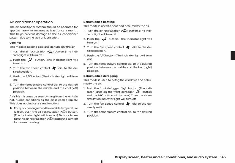
Air conditioner operationThe air conditioner system should be operated forapproximately 10 minutes at least once a month.This helps prevent damage to the air conditionersystem due to the lack of lubrication.
Cooling:This mode is used to cool and dehumidify the air.
1. Push the air recirculation button. (The indi-cator light will turn off.)
2. Push the button. (The indicator light willturn on.)
3. Turn the fan speed control dial to the de-sired position.
4. Push the A/C button. (The indicator light will turnon.)
5. Turn the temperature control dial to the desiredposition between the middle and the cool (left)position.
A visible mist may be seen coming from the vents inhot, humid conditions as the air is cooled rapidly.This does not indicate a malfunction.
• For quick cooling when the outside temperatureis high, push the air recirculation button.(The indicator light will turn on.) Be sure to re-turn the air recirculation button to turn offfor normal cooling.
Dehumidified heating:This mode is used to heat and dehumidify the air.
1. Push the air recirculation button. (The indi-cator light will turn off.)
2. Push the button. (The indicator light willturn on.)
3. Turn the fan speed control dial to the de-sired position.
4. Push the A/C button. (The indicator light will turnon.)
5. Turn the temperature control dial to the desiredposition between the middle and the hot (right)position.
Dehumidified defogging:This mode is used to defog the windows and dehu-midify the air.
1. Push the front defogger button. (The indi-cator lights on the front defogger buttonand the A/C button will turn on.) Then the air re-circulation indicator light will turn off.
2. Turn the fan speed control dial to the de-sired position.
3. Turn the temperature control dial to the desiredposition.
Display screen, heater and air conditioner, and audio system 143
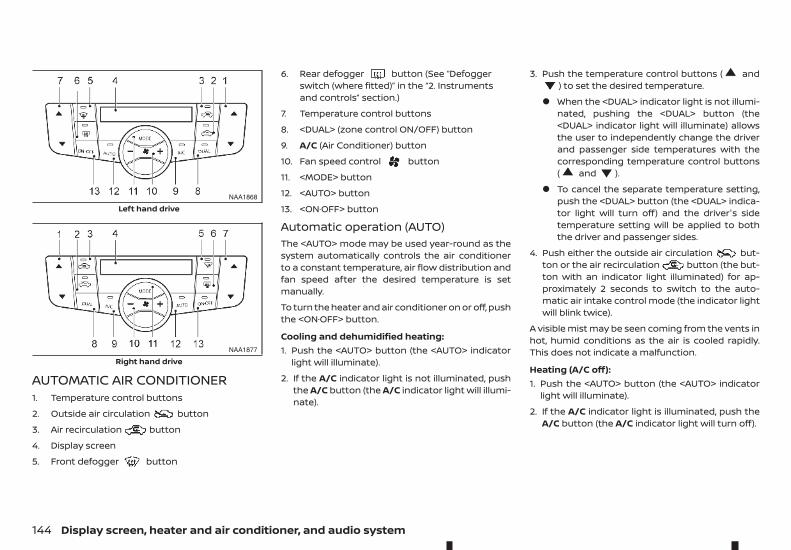
AUTOMATIC AIR CONDITIONER1. Temperature control buttons
2. Outside air circulation button
3. Air recirculation button
4. Display screen
5. Front defogger button
6. Rear defogger button (See “Defoggerswitch (where fitted)” in the “2. Instrumentsand controls” section.)
7. Temperature control buttons
8. <DUAL> (zone control ON/OFF) button
9. A/C (Air Conditioner) button
10. Fan speed control button
11. <MODE> button
12. <AUTO> button
13. <ON·OFF> button
Automatic operation (AUTO)The <AUTO> mode may be used year-round as thesystem automatically controls the air conditionerto a constant temperature, air flow distribution andfan speed after the desired temperature is setmanually.
To turn the heater and air conditioner on or off, pushthe <ON·OFF> button.
Cooling and dehumidified heating:1. Push the <AUTO> button (the <AUTO> indicator
light will illuminate).
2. If the A/C indicator light is not illuminated, pushthe A/C button (the A/C indicator light will illumi-nate).
3. Push the temperature control buttons ( and) to set the desired temperature.
• When the <DUAL> indicator light is not illumi-nated, pushing the <DUAL> button (the<DUAL> indicator light will illuminate) allowsthe user to independently change the driverand passenger side temperatures with thecorresponding temperature control buttons( and ).
• To cancel the separate temperature setting,push the <DUAL> button (the <DUAL> indica-tor light will turn off) and the driver's sidetemperature setting will be applied to boththe driver and passenger sides.
4. Push either the outside air circulation but-ton or the air recirculation button (the but-ton with an indicator light illuminated) for ap-proximately 2 seconds to switch to the auto-matic air intake control mode (the indicator lightwill blink twice).
A visible mist may be seen coming from the vents inhot, humid conditions as the air is cooled rapidly.This does not indicate a malfunction.
Heating (A/C off):1. Push the <AUTO> button (the <AUTO> indicator
light will illuminate).
2. If the A/C indicator light is illuminated, push theA/C button (the A/C indicator light will turn off).
NAA1868
Left hand drive
NAA1877
Right hand drive
144 Display screen, heater and air conditioner, and audio system
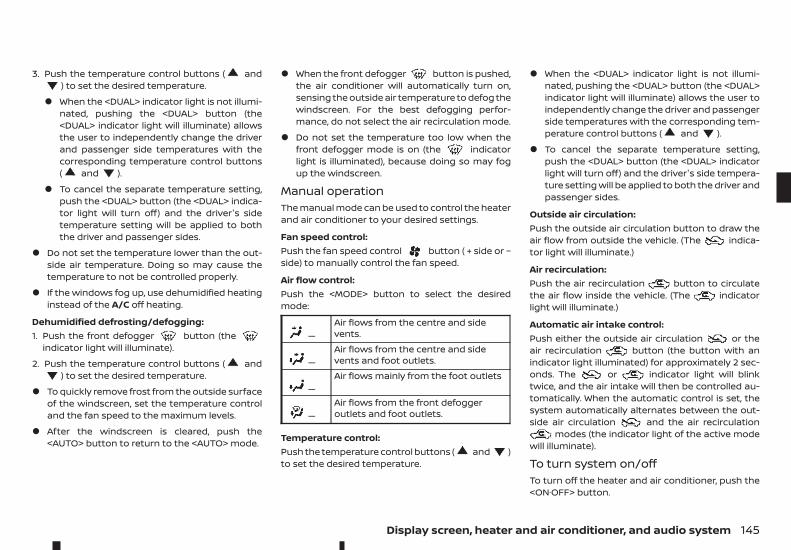
3. Push the temperature control buttons ( and) to set the desired temperature.
• When the <DUAL> indicator light is not illumi-nated, pushing the <DUAL> button (the<DUAL> indicator light will illuminate) allowsthe user to independently change the driverand passenger side temperatures with thecorresponding temperature control buttons( and ).
• To cancel the separate temperature setting,push the <DUAL> button (the <DUAL> indica-tor light will turn off) and the driver's sidetemperature setting will be applied to boththe driver and passenger sides.
• Do not set the temperature lower than the out-side air temperature. Doing so may cause thetemperature to not be controlled properly.
• If the windows fog up, use dehumidified heatinginstead of the A/C off heating.
Dehumidified defrosting/defogging:1. Push the front defogger button (the
indicator light will illuminate).
2. Push the temperature control buttons ( and) to set the desired temperature.
• To quickly remove frost from the outside surfaceof the windscreen, set the temperature controland the fan speed to the maximum levels.
• After the windscreen is cleared, push the<AUTO> button to return to the <AUTO> mode.
• When the front defogger button is pushed,the air conditioner will automatically turn on,sensing the outside air temperature to defog thewindscreen. For the best defogging perfor-mance, do not select the air recirculation mode.
• Do not set the temperature too low when thefront defogger mode is on (the indicatorlight is illuminated), because doing so may fogup the windscreen.
Manual operationThe manual mode can be used to control the heaterand air conditioner to your desired settings.
Fan speed control:Push the fan speed control button ( + side or −side) to manually control the fan speed.
Air flow control:Push the <MODE> button to select the desiredmode:
m—Air flows from the centre and sidevents.
m—Air flows from the centre and sidevents and foot outlets.
m—Air flows mainly from the foot outlets
m—Air flows from the front defoggeroutlets and foot outlets.
Temperature control:Push the temperature control buttons ( and )to set the desired temperature.
• When the <DUAL> indicator light is not illumi-nated, pushing the <DUAL> button (the <DUAL>indicator light will illuminate) allows the user toindependently change the driver and passengerside temperatures with the corresponding tem-perature control buttons ( and ).
• To cancel the separate temperature setting,push the <DUAL> button (the <DUAL> indicatorlight will turn off) and the driver's side tempera-ture setting will be applied to both the driver andpassenger sides.
Outside air circulation:Push the outside air circulation button to draw theair flow from outside the vehicle. (The indica-tor light will illuminate.)
Air recirculation:Push the air recirculation button to circulatethe air flow inside the vehicle. (The indicatorlight will illuminate.)
Automatic air intake control:Push either the outside air circulation or theair recirculation button (the button with anindicator light illuminated) for approximately 2 sec-onds. The or indicator light will blinktwice, and the air intake will then be controlled au-tomatically. When the automatic control is set, thesystem automatically alternates between the out-side air circulation and the air recirculation
modes (the indicator light of the active modewill illuminate).
To turn system on/offTo turn off the heater and air conditioner, push the<ON·OFF> button.
Display screen, heater and air conditioner, and audio system 145
SERVICING AIR CONDITIONER
WARNINGThe air conditioner system contains refrigerantunder high pressure. To avoid personal injury, anyair conditioner service should be done only by anexperienced technician with the properequipment.
The air conditioner system in your vehicle is chargedwith a refrigerant designed with the environment inmind.
This refrigerant will not harm the earth’s ozonelayer. However, it may contribute in a small part toglobal warming.
Special charging equipment and lubricant are re-quired when servicing your vehicle’s air conditioner.Using improper refrigerants or lubricants will causesevere damage to the air conditioner system. (See“Recommended fluids/lubricants and capacities” inthe “9. Technical information” section.)
An approved dealer or qualified workshop will beable to service your environmentally friendly airconditioner system.
Air conditioner filterThe air conditioner system is equipped with an airconditioner filter which collects and neutralises dirt,pollen, dust, etc. To make sure that the air condi-tioner heats, defogs and ventilates efficiently, re-place the filter in accordance with the specifiedmaintenance intervals listed in the separate main-tenance booklet. To replace the filter, contact an ap-proved dealer or qualified workshop.
The filter should be replaced if the air flow decreasessignificantly or if windows fog up easily when oper-ating the heater or air conditioner.
AUDIO OPERATION PRECAUTIONS
WARNINGDo not adjust the audio system while driving sothat full attention may be given to vehicleoperation.
Radio• Radio reception is affected by station signal
strength, distance from radio transmitter, build-ings, bridges, mountains and other external in-fluences. Intermittent changes in receptionquality normally are caused by these externalinfluences.
• Using a mobile phone in or near the vehicle mayinfluence radio reception quality.
AUDIO SYSTEM (where fitted)
146 Display screen, heater and air conditioner, and audio system
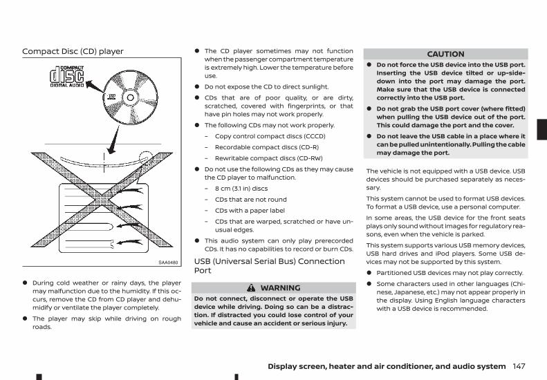
Compact Disc (CD) player
• During cold weather or rainy days, the playermay malfunction due to the humidity. If this oc-curs, remove the CD from CD player and dehu-midify or ventilate the player completely.
• The player may skip while driving on roughroads.
• The CD player sometimes may not functionwhen the passenger compartment temperatureis extremely high. Lower the temperature beforeuse.
• Do not expose the CD to direct sunlight.
• CDs that are of poor quality, or are dirty,scratched, covered with fingerprints, or thathave pin holes may not work properly.
• The following CDs may not work properly.
– Copy control compact discs (CCCD)
– Recordable compact discs (CD-R)
– Rewritable compact discs (CD-RW)
• Do not use the following CDs as they may causethe CD player to malfunction.
– 8 cm (3.1 in) discs
– CDs that are not round
– CDs with a paper label
– CDs that are warped, scratched or have un-usual edges.
• This audio system can only play prerecordedCDs. It has no capabilities to record or burn CDs.
USB (Universal Serial Bus) ConnectionPort
WARNINGDo not connect, disconnect or operate the USBdevice while driving. Doing so can be a distrac-tion. If distracted you could lose control of yourvehicle and cause an accident or serious injury.
CAUTION• Do not force the USB device into the USB port.
Inserting the USB device tilted or up-side-down into the port may damage the port.Make sure that the USB device is connectedcorrectly into the USB port.
• Do not grab the USB port cover (where fitted)when pulling the USB device out of the port.This could damage the port and the cover.
• Do not leave the USB cable in a place where itcan be pulled unintentionally. Pulling the cablemay damage the port.
The vehicle is not equipped with a USB device. USBdevices should be purchased separately as neces-sary.
This system cannot be used to format USB devices.To format a USB device, use a personal computer.
In some areas, the USB device for the front seatsplays only sound without images for regulatory rea-sons, even when the vehicle is parked.
This system supports various USB memory devices,USB hard drives and iPod players. Some USB de-vices may not be supported by this system.
• Partitioned USB devices may not play correctly.
• Some characters used in other languages (Chi-nese, Japanese, etc.) may not appear properly inthe display. Using English language characterswith a USB device is recommended.
SAA0480
Display screen, heater and air conditioner, and audio system 147
General notes for USB use:
Refer to your device manufacturer's owner infor-mation regarding the proper use and care of thedevice.
Notes for iPod use:
iPod is a trademark of Apple Inc., registered in theU.S. and other countries.
• Improperly plugging in the iPod may cause acheckmark to be displayed on and off (flicker-ing). Always make sure that the iPod isconnected properly.
• An iPod nano (1st Generation) may remain in fastforward or rewind mode if it is connected duringa seek operation. In this case, please manuallyreset the iPod.
• An iPod nano (2nd Generation) will continue tofast-forward or rewind if it is disconnected dur-ing a seek operation.
• An incorrect song title may appear when thePlay Mode is changed while using an iPod nano(2nd Generation).
• Audiobooks may not play in the same order asthey appear on an iPod.
• Large video files cause slow responses in aniPod. The vehicle centre display may momen-tarily black out, but will soon recover.
• If an iPod automatically selects large video fileswhile in the shuffle mode, the vehicle centre dis-play may momentarily black out, but will soonrecover.
Bluetooth® audio player (where fitted)• Some Bluetooth® audio devices may not be used
with this system. For detailed information aboutBluetooth® audio devices that are available foruse with this system, contact an approveddealer or qualified workshop.
• Before using a Bluetooth® audio system, the ini-tial registration process for the audio device isnecessary.
• Operation of the Bluetooth® audio system mayvary depending on the audio device that is con-nected. Confirm the operation procedure beforeuse.
• The playback of Bluetooth® audio will be pausedunder the following conditions. The playback willbe resumed after the following conditions arecompleted.
– while using a hands-free phone
– while checking a connection with a mobilephone
• The in-vehicle antenna for Bluetooth® commu-nication is built in the system. Do not place theBluetooth® audio device in an area surroundedby metal, far away from the system or in a nar-row space where the device closely contacts thebody or the seat. Otherwise, sound degradationor connection interference may occur.
• While a Bluetooth® audio device is connectedthrough the Bluetooth® wireless connection, thebattery power of the device may dischargequicker than usual.
• This system is compatible with the Bluetooth®AV profile (A2DP and AVRCP).
mBluetooth® is a trademarkowned by Bluetooth SIG, Inc.,and licensed to Visteon Corpo-ration and Robert BoschGmbH.
Compact Disc (CD)/USB device withMP3/WMA/AAC (where fitted)Terms:• MP3 — MP3 is short for Moving Pictures Experts
Group Audio Layer 3. MP3 is the most well knowncompressed digital audio file format. This formatallows for near “CD quality” sound, but at a frac-tion of the size of normal audio files. MP3 con-version of an audio track from CD can reducethe file size by approximately 10:1 ratio (Sampling:44.1 kHz, Bit rate: 128 kbps) with virtually no per-ceptible loss in quality. MP3 compressionremoves the redundant and irrelevant parts of asound signal that the human ear doesn’t hear.
• WMA — Windows Media Audio (WMA) is a com-pressed audio format created by Microsoft asan alternative to MP3. The WMA codec offersgreater file compression than the MP3 codec,enabling storage of more digital audio tracks inthe same amount of space when compared toMP3s at the same level of quality.
• AAC (where fitted) — Advanced Audio Coding(AAC) is a compressed audio format. AAC offersgreater file compression than MP3 and enablesmusic file creation and storage at the same qual-ity as MP3.
148 Display screen, heater and air conditioner, and audio system
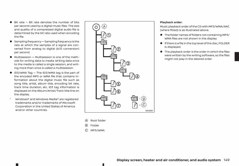
• Bit rate — Bit rate denotes the number of bitsper second used by a digital music files. The sizeand quality of a compressed digital audio file isdetermined by the bit rate used when encodingthe file.
• Sampling frequency — Sampling frequency is therate at which the samples of a signal are con-verted from analog to digital (A/D conversion)per second.
• Multisession — Multisession is one of the meth-ods for writing data to media. Writing data onceto the media is called a single session, and writ-ing more than once is called a multisession.
• ID3/WMA Tag — The ID3/WMA tag is the part ofthe encoded MP3 or WMA file that contains in-formation about the digital music file such assong title, artist, album title, encoding bit rate,track time duration, etc. ID3 tag information isdisplayed on the Album/Artist/Track title line onthe display.
* Windows® and Windows Media® are registeredtrademarks and/or trademarks of MicrosoftCorporation in the United States of Americaand/or other countries.
jA Root folderjB FolderjC MP3/WMA
Playback order:Music playback order of the CD with MP3/WMA/AAC(where fitted) is as illustrated above.
• The folder names of folders not containing MP3/WMA files are not shown in the display.
• If there is a file in the top level of the disc, FOLDERis displayed.
• The playback order is the order in which the fileswere written by the writing software, so the filesmight not play in the desired order.
NAA984
Display screen, heater and air conditioner, and audio system 149
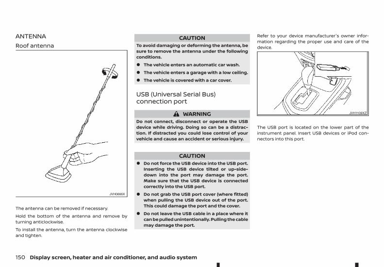
ANTENNARoof antenna
The antenna can be removed if necessary.
Hold the bottom of the antenna and remove byturning anticlockwise.
To install the antenna, turn the antenna clockwiseand tighten.
CAUTIONTo avoid damaging or deforming the antenna, besure to remove the antenna under the followingconditions.
• The vehicle enters an automatic car wash.
• The vehicle enters a garage with a low ceiling.
• The vehicle is covered with a car cover.
USB (Universal Serial Bus)connection port
WARNINGDo not connect, disconnect or operate the USBdevice while driving. Doing so can be a distrac-tion. If distracted you could lose control of yourvehicle and cause an accident or serious injury.
CAUTION• Do not force the USB device into the USB port.
Inserting the USB device tilted or up-side-down into the port may damage the port.Make sure that the USB device is connectedcorrectly into the USB port.
• Do not grab the USB port cover (where fitted)when pulling the USB device out of the port.This could damage the port and the cover.
• Do not leave the USB cable in a place where itcan be pulled unintentionally. Pulling the cablemay damage the port.
Refer to your device manufacturer's owner infor-mation regarding the proper use and care of thedevice.
The USB port is located on the lower part of theinstrument panel. Insert USB devices or iPod con-nectors into this port.
JVH0666X
JVH1109XZ
150 Display screen, heater and air conditioner, and audio system
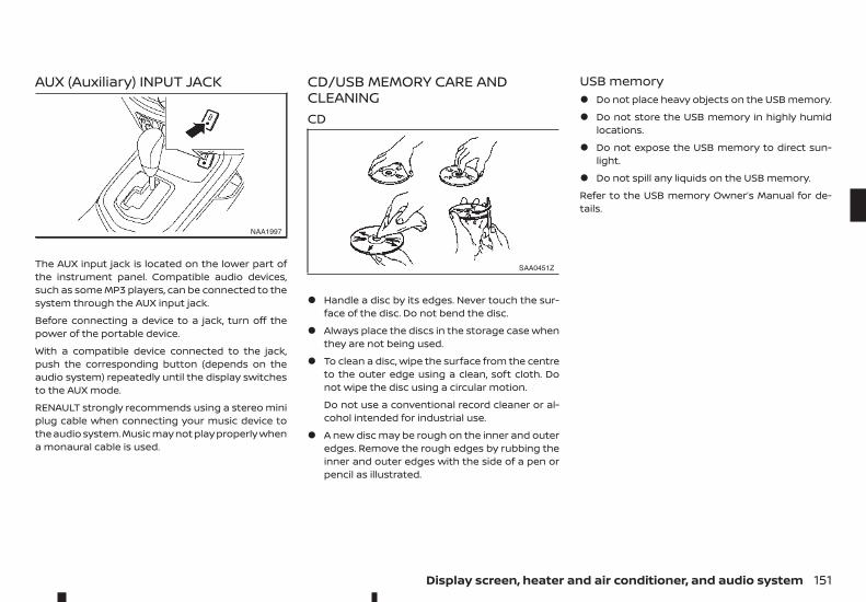
AUX (Auxiliary) INPUT JACK
The AUX input jack is located on the lower part ofthe instrument panel. Compatible audio devices,such as some MP3 players, can be connected to thesystem through the AUX input jack.
Before connecting a device to a jack, turn off thepower of the portable device.
With a compatible device connected to the jack,push the corresponding button (depends on theaudio system) repeatedly until the display switchesto the AUX mode.
RENAULT strongly recommends using a stereo miniplug cable when connecting your music device tothe audio system. Music may not play properly whena monaural cable is used.
CD/USB MEMORY CARE ANDCLEANINGCD
• Handle a disc by its edges. Never touch the sur-face of the disc. Do not bend the disc.
• Always place the discs in the storage case whenthey are not being used.
• To clean a disc, wipe the surface from the centreto the outer edge using a clean, soft cloth. Donot wipe the disc using a circular motion.
Do not use a conventional record cleaner or al-cohol intended for industrial use.
• A new disc may be rough on the inner and outeredges. Remove the rough edges by rubbing theinner and outer edges with the side of a pen orpencil as illustrated.
USB memory• Do not place heavy objects on the USB memory.
• Do not store the USB memory in highly humidlocations.
• Do not expose the USB memory to direct sun-light.
• Do not spill any liquids on the USB memory.
Refer to the USB memory Owner’s Manual for de-tails.
NAA1997
SAA0451Z
Display screen, heater and air conditioner, and audio system 151
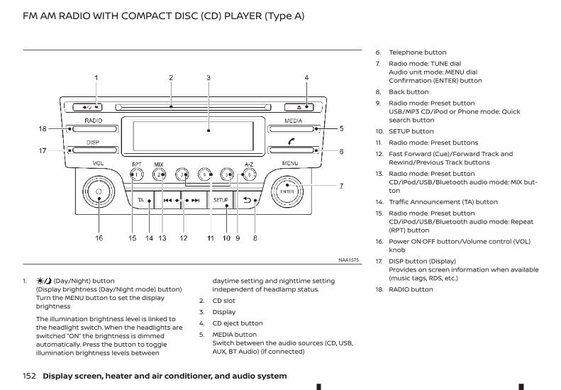
1. (Day/Night) button(Display brightness (Day/Night mode) button)Turn the MENU button to set the displaybrightness
The illumination brightness level is linked tothe headlight switch. When the headlights areswitched “ON” the brightness is dimmedautomatically. Press the button to toggleillumination brightness levels between
daytime setting and nighttime settingindependent of headlamp status.
2. CD slot
3. Display
4. CD eject button
5. MEDIA buttonSwitch between the audio sources (CD, USB,AUX, BT Audio) (if connected)
6. Telephone button
7. Radio mode: TUNE dialAudio unit mode: MENU dialConfirmation (ENTER) button
8. Back button
9. Radio mode: Preset buttonUSB/MP3 CD/iPod or Phone mode: Quicksearch button
10. SETUP button
11. Radio mode: Preset buttons
12. Fast Forward (Cue)/Forward Track andRewind/Previous Track buttons
13. Radio mode: Preset buttonCD/iPod/USB/Bluetooth audio mode: MIX but-ton
14. Traffic Announcement (TA) button
15. Radio mode: Preset buttonCD/iPod/USB/Bluetooth audio mode: Repeat(RPT) button
16. Power ON·OFF button/Volume control (VOL)knob
17. DISP button (Display)Provides on screen information when available(music tags, RDS, etc.)
18. RADIO button
NAA1575
FM AM RADIO WITH COMPACT DISC (CD) PLAYER (Type A)
152 Display screen, heater and air conditioner, and audio system
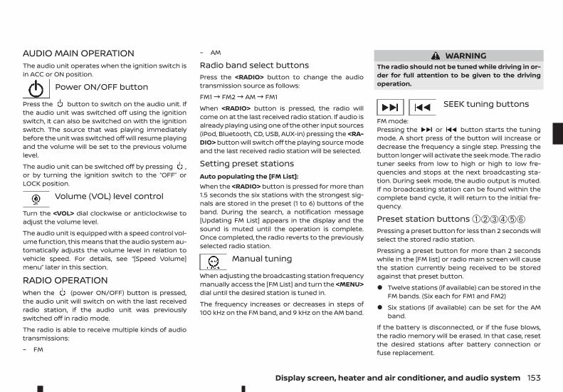
AUDIO MAIN OPERATIONThe audio unit operates when the ignition switch isin ACC or ON position.
m Power ON/OFF button
Press the button to switch on the audio unit. Ifthe audio unit was switched off using the ignitionswitch, it can also be switched on with the ignitionswitch. The source that was playing immediatelybefore the unit was switched off will resume playingand the volume will be set to the previous volumelevel.
The audio unit can be switched off by pressing ,or by turning the ignition switch to the “OFF” orLOCK position.
Volume (VOL) level control
Turn the <VOL> dial clockwise or anticlockwise toadjust the volume level.
The audio unit is equipped with a speed control vol-ume function, this means that the audio system au-tomatically adjusts the volume level in relation tovehicle speed. For details, see “[Speed Volume]menu” later in this section.
RADIO OPERATIONWhen the (power ON/OFF) button is pressed,the audio unit will switch on with the last receivedradio station, if the audio unit was previouslyswitched off in radio mode.
The radio is able to receive multiple kinds of audiotransmissions:
– FM
– AM
Radio band select buttonsPress the <RADIO> button to change the audiotransmission source as follows:
FM1! FM2! AM! FM1
When <RADIO> button is pressed, the radio willcome on at the last received radio station. If audio isalready playing using one of the other input sources(iPod, Bluetooth, CD, USB, AUX-in) pressing the <RA-DIO> button will switch off the playing source modeand the last received radio station will be selected.
Setting preset stationsAuto populating the [FM List]:When the <RADIO> button is pressed for more than1.5 seconds the six stations with the strongest sig-nals are stored in the preset (1 to 6) buttons of theband. During the search, a notification message[Updating FM List] appears in the display and thesound is muted until the operation is complete.Once completed, the radio reverts to the previouslyselected radio station.
Manual tuning
When adjusting the broadcasting station frequencymanually access the [FM List] and turn the <MENU>dial until the desired station is tuned in.
The frequency increases or decreases in steps of100 kHz on the FM band, and 9 kHz on the AM band.
WARNINGThe radio should not be tuned while driving in or-der for full attention to be given to the drivingoperation.
SEEK tuning buttons
FM mode:Pressing the or button starts the tuningmode. A short press of the button will increase ordecrease the frequency a single step. Pressing thebutton longer will activate the seek mode. The radiotuner seeks from low to high or high to low fre-quencies and stops at the next broadcasting sta-tion. During seek mode, the audio output is muted.If no broadcasting station can be found within thecomplete band cycle, it will return to the initial fre-quency.
Preset station buttons ➀➁➂➃➄➅Pressing a preset button for less than 2 seconds willselect the stored radio station.
Pressing a preset button for more than 2 secondswhile in the [FM list] or radio main screen will causethe station currently being received to be storedagainst that preset button.
• Twelve stations (if available) can be stored in theFM bands. (Six each for FM1 and FM2)
• Six stations (if available) can be set for the AMband.
If the battery is disconnected, or if the fuse blows,the radio memory will be erased. In that case, resetthe desired stations after battery connection orfuse replacement.
Display screen, heater and air conditioner, and audio system 153
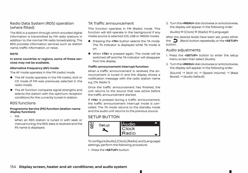
Radio Data System (RDS) operation(where fitted)The RDS is a system through which encoded digitalinformation is transmitted by FM radio stations inaddition to the normal FM radio broadcasting. TheRDS provides information services such as stationname, traffic information, or news.
NOTE
In some countries or regions, some of these ser-vices may not be available.
Alternative Frequency (AF) mode:The AF mode operates in the FM (radio) mode.
• The AF mode operates in the FM (radio), AUX orCD mode (if FM was previously selected in theradio mode).
• The AF function compares signal strengths andselects the station with the optimum receptionconditions for the currently tuned-in station.
RDS functionsProgramme Service (PS) function (station namedisplay function):– FM:
When an RDS station is tuned in with seek ormanual tuning, the RDS data is received and thePS name is displayed.
TA Traffic announcementThis function operates in FM (Radio) mode. Thisfunction will still operate in the background if anymedia source is selected (CD, USB or MEDIA mode).
• Pressing the <TA> button selects the TA mode.The TA indicator is displayed while TA mode ison.
• When <TA> is pressed again. The mode will beswitched off and the TA indicator will disappearfrom the display.
Traffic announcement interrupt function:When a traffic announcement is received, the an-nouncement is tuned in and the display shows anotification message with the radio station namee.g. [TA: Radio 1].
Once the traffic announcement has finished, theunit returns to the source that was active beforethe traffic announcement started.
If <TA> is pressed during a traffic announcement,the traffic announcement interrupt mode is can-celled. The TA mode returns to the standby modeand the audio unit returns to the previous source.
SETUP BUTTON
To configure [Audio], [Clock], [Radio], and [Language]settings, perform the following procedure:
1. Press the <SETUP> button.
2. Turn the <MENU> dial clockwise or anticlockwise,the display will appear in the following order:
[Audio]# [Clock]# [Radio]# [Language]
After the desired levels have been set, press eitherthe (Back) button repeatedly, or the <SETUP>button.
Audio adjustments1. Press the <SETUP> button to enter the setup
menu screen then select [Audio].
2. Turn the <MENU> dial clockwise or anticlockwise,the display will appear in the following order:
[Sound] ! [AUX in] ! [Speed Volume] ! [BassBoost]! [Audio Default]
154 Display screen, heater and air conditioner, and audio system
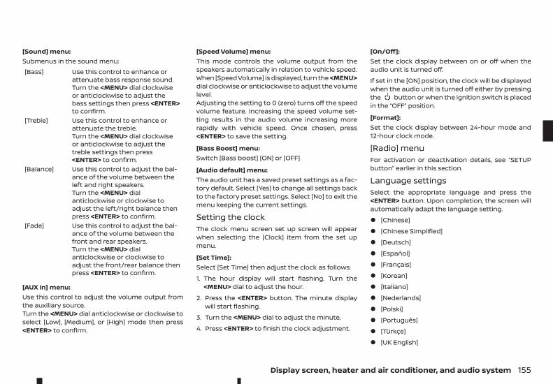
[Sound] menu:Submenus in the sound menu:[Bass] Use this control to enhance or
attenuate bass response sound.Turn the <MENU> dial clockwiseor anticlockwise to adjust thebass settings then press <ENTER>to confirm.
[Treble] Use this control to enhance orattenuate the treble.Turn the <MENU> dial clockwiseor anticlockwise to adjust thetreble settings then press<ENTER> to confirm.
[Balance] Use this control to adjust the bal-ance of the volume between theleft and right speakers.Turn the <MENU> dialanticlockwise or clockwise toadjust the left/right balance thenpress <ENTER> to confirm.
[Fade] Use this control to adjust the bal-ance of the volume between thefront and rear speakers.Turn the <MENU> dialanticlockwise or clockwise toadjust the front/rear balance thenpress <ENTER> to confirm.
[AUX in] menu:Use this control to adjust the volume output fromthe auxiliary source.Turn the <MENU> dial anticlockwise or clockwise toselect [Low], [Medium], or [High] mode then press<ENTER> to confirm.
[Speed Volume] menu:This mode controls the volume output from thespeakers automatically in relation to vehicle speed.When [Speed Volume] is displayed, turn the <MENU>dial clockwise or anticlockwise to adjust the volumelevel.Adjusting the setting to 0 (zero) turns off the speedvolume feature. Increasing the speed volume set-ting results in the audio volume increasing morerapidly with vehicle speed. Once chosen, press<ENTER> to save the setting.
[Bass Boost] menu:Switch [Bass boost] [ON] or [OFF]
[Audio default] menu:The audio unit has a saved preset settings as a fac-tory default. Select [Yes] to change all settings backto the factory preset settings. Select [No] to exit themenu keeping the current settings.
Setting the clockThe clock menu screen set up screen will appearwhen selecting the [Clock] item from the set upmenu.
[Set Time]:Select [Set Time] then adjust the clock as follows:
1. The hour display will start flashing. Turn the<MENU> dial to adjust the hour.
2. Press the <ENTER> button. The minute displaywill start flashing.
3. Turn the <MENU> dial to adjust the minute.
4. Press <ENTER> to finish the clock adjustment.
[On/Off]:Set the clock display between on or off when theaudio unit is turned off.
If set in the [ON] position, the clock will be displayedwhen the audio unit is turned off either by pressingthe button or when the ignition switch is placedin the “OFF” position.
[Format]:Set the clock display between 24-hour mode and12-hour clock mode.
[Radio] menuFor activation or deactivation details, see “SETUPbutton” earlier in this section.
Language settingsSelect the appropriate language and press the<ENTER> button. Upon completion, the screen willautomatically adapt the language setting.
• [Chinese]
• [Chinese Simplified]
• [Deutsch]
• [Español]
• [Français]
• [Korean]
• [Italiano]
• [Nederlands]
• [Polski]
• [Português]
• [Türkçe]
• [UK English]
Display screen, heater and air conditioner, and audio system 155
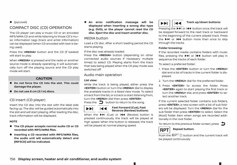
• [русский]
COMPACT DISC (CD) OPERATIONThe CD player can play a music CD or an encodedMP3/WMA CD and while listening to those CD's mu-sic information tags (track and artist information)can be displayed (when CD encoded with text is be-ing used).
Press the <MEDIA> button and the CD (if loaded)will start to play.
When <MEDIA> is pressed and the radio or anothersource mode is already operating, it will automati-cally turn off the playing source and the CD playmode will start.
CAUTION• Do not force the CD into the slot. This could
damage the player.
• Do not use 8 cm (3.1 in) discs.
CD insert (CD player)Insert the CD disc into the slot with the label sidefacing up. The disc will be guided automatically intothe slot and will start playing. After loading the disc,track information will be displayed.
NOTE
• The CD player accepts normal audio CD or CDrecorded with MP3/WMA files.
• Inserting a CD recorded with MP3/WMA files,the audio unit will automatically detect and[MP3CD] will be indicated.
• An error notification message will bedisplayed when inserting a wrong disc type(e.g. DVD), or the player cannot read the CDdisc. Eject the disc and insert another disc.
MEDIA buttonLoad a CD disc. After a short loading period the CDstarts playing.
If the disc was already loaded:Press the <MEDIA> button (depending on otherconnected audio sources if necessary multipletimes) to select CD. Playing starts from the trackthat was being played when the CD play mode wasswitched off.
Audio main operationList view:While the track is being played, either press the<ENTER> button or turn the <MENU> dial to displaythe available tracks in a listed view mode. To selecta track from the list, or a track to start listening from,turn the <MENU> dial then press <ENTER>.Press the button to return to the song.
Fast Forward (Cue), FastReverse (Review) buttons:
When the (Cue) or (Review) button ispressed continuously, the track will be played athigh speed. When the button is released, the trackwill be played at normal playing speed.
Track up/down buttons:
Pressing the or button once, the track willbe skipped forward to the next track or backwardto the beginning of the current played track. Pressthe or button more than once to skipthrough the tracks.
Folder browsing:If the recorded media contains folders with musicfiles, pressing the or button will play insequence the tracks of each folder.
To select a preferred folder:
1. Press the <ENTER> button or turn the <MENU>dial and a list of tracks in the current folder is dis-played.
2. Turn the <MENU> dial for the preferred folder.
3. Press <ENTER> to access the folder. Press<ENTER> again to start playing the first track orturn the <MENU> dial, and press <ENTER> to se-lect another track.
If the current selected folder contains sub folders,press <ENTER>, a new screen with a list of sub fold-ers will be displayed. Turn the <MENU> dial for thesub folder then press <ENTER> to select. Select the[Root] folder item when songs are recorded addi-tionally in the root folder.
To return to the previous folder screen, press .
Repeat button:
Push the ➀ button and the current track willbe played continuously.
156 Display screen, heater and air conditioner, and audio system
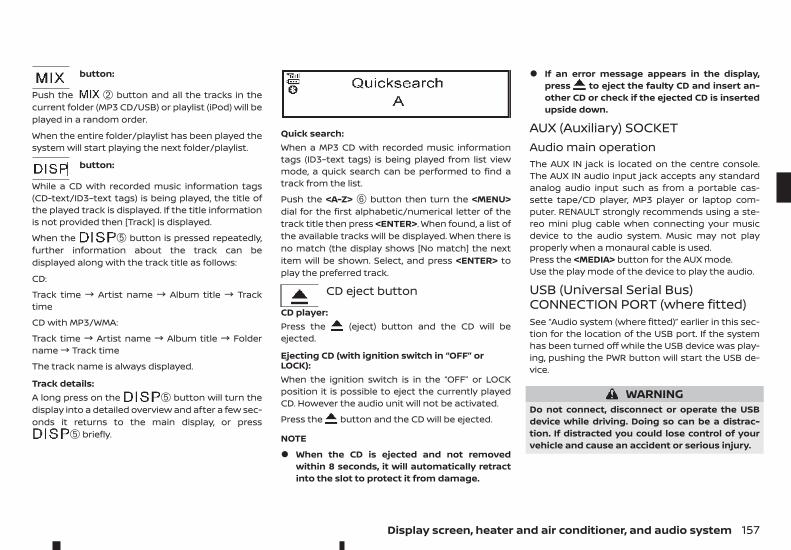
button:
Push the ➁ button and all the tracks in thecurrent folder (MP3 CD/USB) or playlist (iPod) will beplayed in a random order.
When the entire folder/playlist has been played thesystem will start playing the next folder/playlist.
button:
While a CD with recorded music information tags(CD-text/ID3–text tags) is being played, the title ofthe played track is displayed. If the title informationis not provided then [Track] is displayed.
When the ➄ button is pressed repeatedly,further information about the track can bedisplayed along with the track title as follows:
CD:
Track time ! Artist name ! Album title ! Tracktime
CD with MP3/WMA:
Track time ! Artist name ! Album title ! Foldername! Track time
The track name is always displayed.
Track details:A long press on the ➄ button will turn thedisplay into a detailed overview and after a few sec-onds it returns to the main display, or press
➄ briefly.
Quick search:When a MP3 CD with recorded music informationtags (ID3–text tags) is being played from list viewmode, a quick search can be performed to find atrack from the list.
Push the <A-Z> ➅ button then turn the <MENU>dial for the first alphabetic/numerical letter of thetrack title then press <ENTER>. When found, a list ofthe available tracks will be displayed. When there isno match (the display shows [No match] the nextitem will be shown. Select, and press <ENTER> toplay the preferred track.
CD eject button
CD player:Press the (eject) button and the CD will beejected.
Ejecting CD (with ignition switch in “OFF” orLOCK):When the ignition switch is in the “OFF” or LOCKposition it is possible to eject the currently playedCD. However the audio unit will not be activated.
Press the button and the CD will be ejected.
NOTE
• When the CD is ejected and not removedwithin 8 seconds, it will automatically retractinto the slot to protect it from damage.
• If an error message appears in the display,press to eject the faulty CD and insert an-other CD or check if the ejected CD is insertedupside down.
AUX (Auxiliary) SOCKETAudio main operationThe AUX IN jack is located on the centre console.The AUX IN audio input jack accepts any standardanalog audio input such as from a portable cas-sette tape/CD player, MP3 player or laptop com-puter. RENAULT strongly recommends using a ste-reo mini plug cable when connecting your musicdevice to the audio system. Music may not playproperly when a monaural cable is used.Press the <MEDIA> button for the AUX mode.Use the play mode of the device to play the audio.
USB (Universal Serial Bus)CONNECTION PORT (where fitted)See “Audio system (where fitted)” earlier in this sec-tion for the location of the USB port. If the systemhas been turned off while the USB device was play-ing, pushing the PWR button will start the USB de-vice.
WARNINGDo not connect, disconnect or operate the USBdevice while driving. Doing so can be a distrac-tion. If distracted you could lose control of yourvehicle and cause an accident or serious injury.
Display screen, heater and air conditioner, and audio system 157
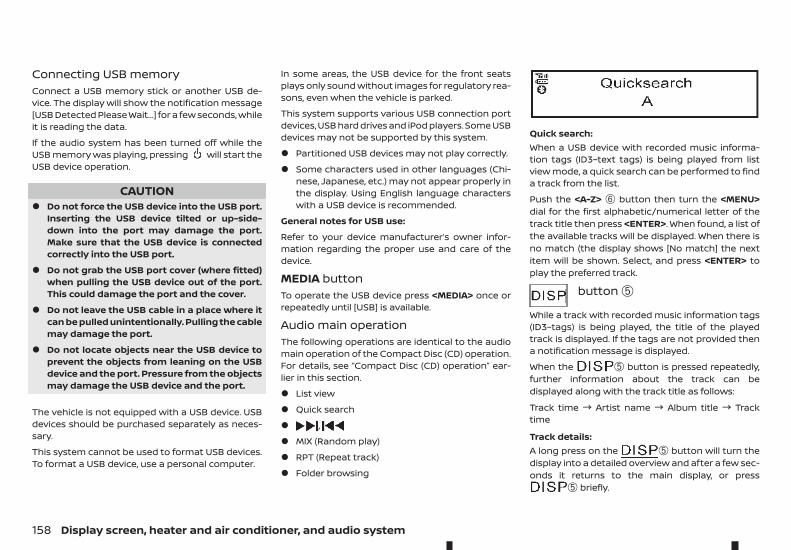
Connecting USB memoryConnect a USB memory stick or another USB de-vice. The display will show the notification message[USB Detected Please Wait...] for a few seconds, whileit is reading the data.
If the audio system has been turned off while theUSB memory was playing, pressing will start theUSB device operation.
CAUTION• Do not force the USB device into the USB port.
Inserting the USB device tilted or up-side-down into the port may damage the port.Make sure that the USB device is connectedcorrectly into the USB port.
• Do not grab the USB port cover (where fitted)when pulling the USB device out of the port.This could damage the port and the cover.
• Do not leave the USB cable in a place where itcan be pulled unintentionally. Pulling the cablemay damage the port.
• Do not locate objects near the USB device toprevent the objects from leaning on the USBdevice and the port. Pressure from the objectsmay damage the USB device and the port.
The vehicle is not equipped with a USB device. USBdevices should be purchased separately as neces-sary.
This system cannot be used to format USB devices.To format a USB device, use a personal computer.
In some areas, the USB device for the front seatsplays only sound without images for regulatory rea-sons, even when the vehicle is parked.
This system supports various USB connection portdevices, USB hard drives and iPod players. Some USBdevices may not be supported by this system.
• Partitioned USB devices may not play correctly.
• Some characters used in other languages (Chi-nese, Japanese, etc.) may not appear properly inthe display. Using English language characterswith a USB device is recommended.
General notes for USB use:
Refer to your device manufacturer’s owner infor-mation regarding the proper use and care of thedevice.
MEDIA buttonTo operate the USB device press <MEDIA> once orrepeatedly until [USB] is available.
Audio main operationThe following operations are identical to the audiomain operation of the Compact Disc (CD) operation.For details, see “Compact Disc (CD) operation” ear-lier in this section.
• List view
• Quick search
• ,
• MIX (Random play)
• RPT (Repeat track)
• Folder browsing
Quick search:When a USB device with recorded music informa-tion tags (ID3–text tags) is being played from listview mode, a quick search can be performed to finda track from the list.
Push the <A-Z> ➅ button then turn the <MENU>dial for the first alphabetic/numerical letter of thetrack title then press <ENTER>. When found, a list ofthe available tracks will be displayed. When there isno match (the display shows [No match] the nextitem will be shown. Select, and press <ENTER> toplay the preferred track.
button ➄
While a track with recorded music information tags(ID3–tags) is being played, the title of the playedtrack is displayed. If the tags are not provided thena notification message is displayed.
When the ➄ button is pressed repeatedly,further information about the track can bedisplayed along with the track title as follows:
Track time ! Artist name ! Album title ! Tracktime
Track details:A long press on the ➄ button will turn thedisplay into a detailed overview and after a few sec-onds it returns to the main display, or press
➄ briefly.
158 Display screen, heater and air conditioner, and audio system
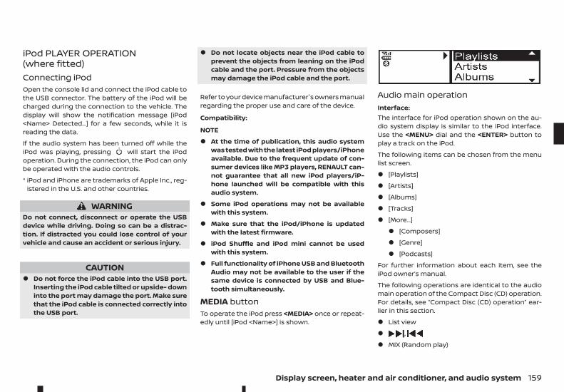
iPod PLAYER OPERATION(where fitted)Connecting iPodOpen the console lid and connect the iPod cable tothe USB connector. The battery of the iPod will becharged during the connection to the vehicle. Thedisplay will show the notification message [iPod<Name> Detected...] for a few seconds, while it isreading the data.
If the audio system has been turned off while theiPod was playing, pressing will start the iPodoperation. During the connection, the iPod can onlybe operated with the audio controls.
* iPod and iPhone are trademarks of Apple Inc., reg-istered in the U.S. and other countries.
WARNINGDo not connect, disconnect or operate the USBdevice while driving. Doing so can be a distrac-tion. If distracted you could lose control of yourvehicle and cause an accident or serious injury.
CAUTION• Do not force the iPod cable into the USB port.
Inserting the iPod cable tilted or upside- downinto the port may damage the port. Make surethat the iPod cable is connected correctly intothe USB port.
• Do not locate objects near the iPod cable toprevent the objects from leaning on the iPodcable and the port. Pressure from the objectsmay damage the iPod cable and the port.
Refer to your device manufacturer's owners manualregarding the proper use and care of the device.
Compatibility:
NOTE
• At the time of publication, this audio systemwas tested with the latest iPod players/iPhoneavailable. Due to the frequent update of con-sumer devices like MP3 players, RENAULT can-not guarantee that all new iPod players/iP-hone launched will be compatible with thisaudio system.
• Some iPod operations may not be availablewith this system.
• Make sure that the iPod/iPhone is updatedwith the latest firmware.
• iPod Shuffle and iPod mini cannot be usedwith this system.
• Full functionality of iPhone USB and BluetoothAudio may not be available to the user if thesame device is connected by USB and Blue-tooth simultaneously.
MEDIA buttonTo operate the iPod press <MEDIA> once or repeat-edly until [iPod <Name>] is shown.
Audio main operationInterface:The interface for iPod operation shown on the au-dio system display is similar to the iPod interface.Use the <MENU> dial and the <ENTER> button toplay a track on the iPod.
The following items can be chosen from the menulist screen.
• [Playlists]
• [Artists]
• [Albums]
• [Tracks]
• [More...]
• [Composers]
• [Genre]
• [Podcasts]
For further information about each item, see theiPod owner’s manual.
The following operations are identical to the audiomain operation of the Compact Disc (CD) operation.For details, see “Compact Disc (CD) operation” ear-lier in this section.
• List view
• ,
• MIX (Random play)
Display screen, heater and air conditioner, and audio system 159
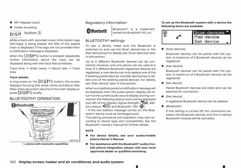
• RPT (Repeat track)
• Folder browsing
button ➄
While a track with recorded music information tags(ID3–tags) is being played, the title of the playedtrack is displayed. If the tags are not provided thena notification message is displayed.
When the ➄ button is pressed repeatedly,further information about the track can bedisplayed along with the track title as follows:
Track time ! Artist name ! Album title ! Tracktime
Track details:A long press on the ➄ button, the screendisplays the song title, artist name, and album title.After a few seconds it returns to the main display orpress ➄ briefly.
BLUETOOTH® OPERATION
Regulatory information
mBluetooth® is a trademarkowned by Bluetooth SIG, Inc.
BLUETOOTH® settingsTo pair a device, make sure the Bluetooth isswitched on and use the [Scan device] key or the[Pair device] key For details, see “[Scan devices]” laterin this section.
Up to 5 different Bluetooth devices can be con-nected. However, only one device can be used at atime. If 5 different Bluetooth registered devices areregistered, a new device can only replace one of the5 existing paired devices. Use [Del. device] key to de-lete one of the existing paired devices. For details,see “[Pair device]” later in this section.
When successfully paired a notification message willbe displayed, then the audio system display will re-turn to the current audio source display. During con-nection the following status icons will be displayed(top left of the display): Signal strength ( ), Bat-tery status* ( ) and Bluetooth “ON” ( ).*: If the low battery message comes on, the Blue-tooth® device must be recharged soon.The pairing procedure and operation may vary ac-cording to device type and compatibility. See theBluetooth® owner’s manual for further details.
NOTE
• For device details, see your audio/mobilephone Owner's Manual.
• For assistance with the Bluetooth® audio/mo-bile phone integration, please visit your localapproved dealer or qualified workshop.
To set up the Bluetooth system with a device thefollowing items are available:
• [Scan devices]
Bluetooth devices can be paired with the sys-tem. A maximum of 5 Bluetooth devices can beregistered.
• [Pair device]
Bluetooth devices can be paired with the sys-tem. A maximum of 5 Bluetooth devices can beregistered.
• [Sel. device]
Paired Bluetooth devices are listed and can beselected for connection.
• [Del. device]
A registered Bluetooth device can be deleted.
• [Bluetooth]
If this setting is turned off, the connection be-tween the Bluetooth devices and the in-vehicleBluetooth module will be cancelled.
NAA1392
*: a device with bluetooth capabilities
160 Display screen, heater and air conditioner, and audio system
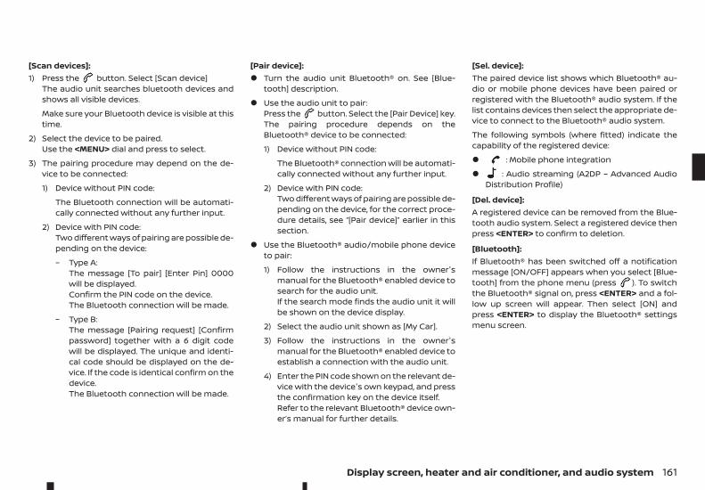
[Scan devices]:1) Press the button. Select [Scan device]
The audio unit searches bluetooth devices andshows all visible devices.
Make sure your Bluetooth device is visible at thistime.
2) Select the device to be paired.Use the <MENU> dial and press to select.
3) The pairing procedure may depend on the de-vice to be connected:
1) Device without PIN code:
The Bluetooth connection will be automati-cally connected without any further input.
2) Device with PIN code:Two different ways of pairing are possible de-pending on the device:
– Type A:The message [To pair] [Enter Pin] 0000will be displayed.Confirm the PIN code on the device.The Bluetooth connection will be made.
– Type B:The message [Pairing request] [Confirmpassword] together with a 6 digit codewill be displayed. The unique and identi-cal code should be displayed on the de-vice. If the code is identical confirm on thedevice.The Bluetooth connection will be made.
[Pair device]:• Turn the audio unit Bluetooth® on. See [Blue-
tooth] description.
• Use the audio unit to pair:Press the button. Select the [Pair Device] key.The pairing procedure depends on theBluetooth® device to be connected:
1) Device without PIN code:
The Bluetooth® connection will be automati-cally connected without any further input.
2) Device with PIN code:Two different ways of pairing are possible de-pending on the device, for the correct proce-dure details, see “[Pair device]” earlier in thissection.
• Use the Bluetooth® audio/mobile phone deviceto pair:
1) Follow the instructions in the owner'smanual for the Bluetooth® enabled device tosearch for the audio unit.If the search mode finds the audio unit it willbe shown on the device display.
2) Select the audio unit shown as [My Car].
3) Follow the instructions in the owner'smanual for the Bluetooth® enabled device toestablish a connection with the audio unit.
4) Enter the PIN code shown on the relevant de-vice with the device's own keypad, and pressthe confirmation key on the device itself.Refer to the relevant Bluetooth® device own-er’s manual for further details.
[Sel. device]:The paired device list shows which Bluetooth® au-dio or mobile phone devices have been paired orregistered with the Bluetooth® audio system. If thelist contains devices then select the appropriate de-vice to connect to the Bluetooth® audio system.
The following symbols (where fitted) indicate thecapability of the registered device:
• : Mobile phone integration
• : Audio streaming (A2DP – Advanced AudioDistribution Profile)
[Del. device]:A registered device can be removed from the Blue-tooth audio system. Select a registered device thenpress <ENTER> to confirm to deletion.
[Bluetooth]:If Bluetooth® has been switched off a notificationmessage [ON/OFF] appears when you select [Blue-tooth] from the phone menu (press ). To switchthe Bluetooth® signal on, press <ENTER> and a fol-low up screen will appear. Then select [ON] andpress <ENTER> to display the Bluetooth® settingsmenu screen.
Display screen, heater and air conditioner, and audio system 161
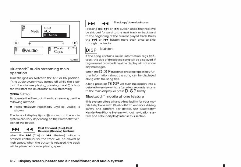
Bluetooth® audio streaming mainoperationTurn the ignition switch to the ACC or ON position.If the audio system was turned off while the Blue-tooth® audio was playing, pressing the < > but-ton will start the Bluetooth® audio streaming.
MEDIA button:To operate the Bluetooth® audio streaming use thefollowing method:
• Press <MEDIA> repeatedly until [BT Audio] isshown.
The type of display, jA or jB , shown on the audiosystem can vary depending on the Bluetooth® ver-sion of the device.
Fast Forward (Cue), FastReverse (Review) buttons:
When the (Cue) or (Review) button ispressed continuously, the track will be played athigh speed. When the button is released, the trackwill be played at normal playing speed.
Track up/down buttons:
Pressing the or button once, the track willbe skipped forward to the next track or backwardto the beginning of the current played track. Pressthe or button more than once to skipthrough the tracks.
button
If the song contains music information tags (ID3–tags), the title of the played song will be displayed. Iftags are not provided then the display will not showany messages.
When the button is pressed repeatedly fur-ther information about the song can be displayedalong with the song title.
A long press on will turn the display into adetailed overview which after a few seconds returnsto the main display; or press briefly.
Bluetooth® mobile phone featureThis system offers a hands-free facility for your mo-bile telephone with Bluetooth® to enhance drivingsafety, and comfort. For details, see “Bluetooth®Hands-Free Phone System (without navigation sys-tem and colour display)” later in this section.
NAA1583
162 Display screen, heater and air conditioner, and audio system
Display screen, heater and air conditioner, and audio system 163
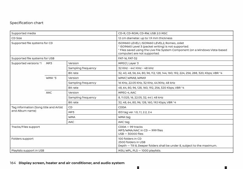
Specification chart
Supported media CD-R, CD-ROM, CD-RW, USB 2.0 MSC
CD Size 12 cm diameter. up to 1.9 mm thickness
Supported file systems for CD ISO9660 LEVEL1, ISO9660 LEVEL2, Romeo, Joliet* ISO9660 Level 3 (packet writing) is not supported.* Files saved using the Live File System Component (on a Windows Vista-basedcomputer) are not supported.
Supported file systems for USB FAT-16, FAT-32
Supported versions *1 MP3 Version MPEG1, Layer 3
Sampling frequency 32 KHz - 44.1 KHz - 48 kHz
Bit rate 32, 40, 48, 56, 64, 80, 96, 112, 128, 144, 160, 192, 224, 256, 288, 320, Kbps, VBR *4
WMA *3 Version WMA7, WMA8, WMA9
Sampling frequency 16 KHz, 22.05 KHz, 32 KHz, 44.1KHz, 48 kHz
Bit rate 48, 64, 80, 96, 128, 160, 192, 256, 320 Kbps, VBR *4
AAC Version MPEG-4, AAC
Sampling frequency 8, 11.025, 16, 22.05, 32, 44.1, 48 kHz
Bit rate 32, 48, 64, 80, 96, 128, 160, 192 Kbps, VBR *4
Tag information (Song title and Artistand Album name)
CD CDDA
MP3 ID3 tag ver. 1.0, 1.1, 2.2, 2.4
WMA WMA tag
AAC AAC tag
Tracks/Files support CDDA — 99 tracksMP3/WMA/AAC in CD — 999 filesUSB — 30000 files
Folders support 100 folders in CD2500 folders in USBDepth — Till 8, Deeper folders shall be under 8, subject to the maximum.
Playlists support in USB M3U, WPL, PLS — 1000 playlists.
164 Display screen, heater and air conditioner, and audio system
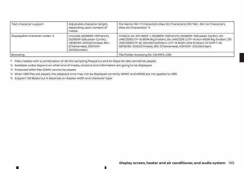
Text character support Adjustable character length,depending upon content ofmedia.
File Name: Min 11 Characters (Max 30 Characters) ID3 TAG : Min 24 Characters.(Max 60 Characters) *5
Displayable character codes *2 Unicode, ISO8859–15(French),ISO8859–5(Russian Cyrillic),GB18030–2000(Chinese), BIG-5(Taiwanese), KSX1001–2002(Korean)
01:ASCll, 02: ISO-8859-1, ISO8859–15(French), ISO8859–5(Russian Cyrillic), 03:UNICODE(UTF-16 BOM Big Endian), 04: UNICODE (UTF-16 Ncn-BOM Big Endian), 05:UNICODE(UTF-8), 06:UNICODE(Non-UTF-16 BOM Little Endian), 07: SHIFT-JIS,GB18030–2000(Chinese), BIG-5(Taiwanese), KSX1001–2002(Korean)
Browsing File/Folder browsing for CD/MP3, USB
*1 Files created with a combination of 48 kHz sampling frequency and 64 Kbps bit rate cannot be played.*2 Available codes depend on what kind of media, versions and information are going to be displayed.*3 Protected WMA files (DRM) cannot be played.*4 When VBR files are played, the playback time may not be displayed correctly. WMA7 and WMA8 are not applied to VBR.*5 Support 128 Bytes but it depends on display width and character type.
Display screen, heater and air conditioner, and audio system 165
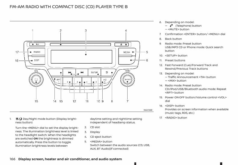
1. Day/Night mode button (Display bright-ness button)
Turn the <MENU> dial to set the display bright-ness. The illumination brightness level is linkedto the headlight switch. When the headlightsare switched ON the brightness is dimmedautomatically. Press the button to toggleillumination brightness levels between
daytime setting and nighttime settingindependent of headlamp status.
2. CD slot
3. Display
4. CD eject button
5. <MEDIA> buttonSwitch between the audio sources (CD, USB,AUX, BT Audio)(if connected)
6. Depending on model:— (Telephone) button— <MUTE> button
7. Confirmation <ENTER> button/ <MENU> dial
8. Back button
9. Radio mode: Preset buttonUSB/MP3 CD or Phone mode: Quick searchbutton
10. <SETUP> button
11. Preset buttons
12. Fast Forward (Cue)/Forward Track andRewind/Previous Track buttons
13. Depending on model:— Traffic Announcement <TA> button— <MIX> button
14. Radio mode: Preset buttonCD/iPod/USB/Bluetooth audio mode: Repeat<RPT> button
15. Power ON·OFF button/Volume control <VOL>dial
16. <DISP> buttonProvides on screen information when available(music tags, RDS, etc.)
17. <RADIO> button
NAA1668
FM-AM RADIO WITH COMPACT DISC (CD) PLAYER TYPE B
166 Display screen, heater and air conditioner, and audio system
AUDIO MAIN OPERATIONThe audio unit operates when the ignition switch isin Acc or ON position.
m Power ON/OFF button
Press the button to switch on the audio unit. Ifthe audio unit was switched off using the ignitionswitch, it can also be switched on with the ignitionswitch. The source that was playing immediatelybefore the unit was switched off will resume playingand the volume will be set to the previous volumelevel.
The audio unit can be switched off by pressing ,or by turning the ignition switch to the OFF or LOCKposition.
Volume (VOL) level control
Turn the <VOL> dial clockwise or anticlockwise toadjust the volume level.
The audio unit is equipped with a speed control vol-ume function, this means that the audio system au-tomatically adjusts the volume level in relation tovehicle speed. For details, see “[Speed Volume]menu” later in this section.
RADIO OPERATIONWhen the (power ON/OFF) button is pressed,the audio unit will switch on with the last receivedradio station, if the audio unit was previouslyswitched off in radio mode.
The radio is able to receive multiple kinds of audiotransmissions:
– FM
– DAB (Digital Audio Broadcasting) indicated as DR(where fitted)
– AM
Radio band select buttonsPress the <RADIO> button to change the audiotransmission source as follows:
FM1! FM2! DR1! DR2! AM! FM1
When <RADIO> button is pressed, the radio willcome on at the last received radio station. If audio isalready playing using one of the other input sources(iPod, Bluetooth, CD, USB, AUX-in) pressing the <RA-DIO> button will switch off the playing source modeand the last received radio station will be selected.
Setting preset stationsAuto populating the [FM List]:When the <RADIO> button is pressed for more than1.5 seconds the six stations with the strongest sig-nals are stored in the preset (1 to 6) buttons of theband. During the search, a notification message[Updating FM List] appears in the display and thesound is muted until the operation is complete.Once completed, the radio reverts to the previouslyselected radio station.
Manual tuning
When adjusting the broadcasting station frequencymanually access the [FM List] and turn the <MENU>dial until the desired station is tuned in.
The frequency increases or decreases in steps of100 kHz on the FM band, and 9 kHz on the AM band.
WARNINGThe radio should not be tuned while driving in or-der for full attention to be given to the drivingoperation.
SEEK tuning buttons
FM mode:Pressing the or button starts the tuningmode. A short press of the button will increase ordecrease the frequency a single step. Pressing thebutton longer will activate the seek mode. The radiotuner seeks from low to high or high to low fre-quencies and stops at the next broadcasting sta-tion. During seek mode, the audio output is muted.If no broadcasting station can be found within thecomplete band cycle, it will return to the initial fre-quency.
DR mode:Press to or select the next or previous sta-tion
Preset station buttons ➀➁➂➃➄➅Pressing a preset button for less than 2 seconds willselect the stored radio station.
Pressing a preset button for more than 2 secondswhile in the [FM list] or radio main screen will causethe station currently being received to be storedagainst that preset button.
• Twelve stations (if available) can be stored in theFM bands. (Six each for FM1 and FM2)
• Twelve stations (if available) can be stored in theDR bands. (Six each for DR1 and DR2) (where fit-ted)
Display screen, heater and air conditioner, and audio system 167
• Six stations (if available) can be set for the AMband.
If the battery is disconnected, or if the fuse blows,the radio memory will be erased. In that case, resetthe desired stations after battery connection orfuse replacement.
DAB and Radio Data System (RDS)operation (where fitted)The RDS is a system through which encoded digitalinformation is transmitted by FM radio stations inaddition to the normal FM radio broadcasting. TheRDS provides information services such as stationname, traffic information, or news.
DAB (Digital Audio Broadcast)
NOTE
• When in DR mode operation is similar to FMmode but may slightly differ.
• In some countries or regions, some of theseservices may not be available.
Alternative Frequency (AF) mode:The AF mode operates in the FM (radio) mode.
• The AF mode operates in the FM (radio), AUX orCD mode (if FM was previously selected in theradio mode).
• The AF function compares signal strengths andselects the station with the optimum receptionconditions for the currently tuned-in station.
DAB and RDS functionsProgramme Service (PS) function (station namedisplay function):– FM:
When an RDS station is tuned in with seek ormanual tuning, the RDS data is received and thePS name is displayed.
– DR:When a station is tuned in with seek or manualtuning, the data is received and the PS name isdisplayed.
TA Traffic announcementThis function operates in FM/DR (Radio) mode. Thisfunction will still operate in the background if anymedia source is selected (CD, USB or MEDIA mode).
• Pressing the <TA> button selects the TA mode.The TA indicator is displayed while TA mode ison.
• When <TA> is pressed again. The mode will beswitched off and the TA indicator will disappearfrom the display.
Traffic announcement interrupt function:When a traffic announcement is received, the an-nouncement is tuned in and the display shows anotification message with the radio station namee.g. [TA: Radio 1].
Once the traffic announcement has finished, theunit returns to the source that was active beforethe traffic announcement started.
If <TA> is pressed during a traffic announcement,the traffic announcement interrupt mode is can-celled. The TA mode returns to the standby modeand the audio unit returns to the previous source.
SETUP BUTTON
To configure [Audio], [Clock], [Radio], and [Language]settings, perform the following procedure:
1. Press the <SETUP> button.
2. Turn the <MENU> dial clockwise or anticlockwise,the display will appear in the following order:
[Audio]# [Clock]# [Radio]# [Language]
After the desired levels have been set, press eitherthe (Back) button repeatedly, or the <SETUP>button.
Audio adjustments1. Press the <SETUP> button to enter the setup
menu screen then select [Audio].
2. Turn the <MENU> dial clockwise or anticlockwise,the display will appear in the following order:
[Sound] ! [AUX in] ! [Speed Volume] ! [BassBoost]! [Audio Default]
168 Display screen, heater and air conditioner, and audio system
[Sound] menu:Submenus in the sound menu:[Bass] Use this control to enhance or
attenuate bass response sound.Turn the <MENU> dial clockwiseor anticlockwise to adjust thebass settings then press <ENTER>to confirm.
[Treble] Use this control to enhance orattenuate the treble.Turn the <MENU> dial clockwiseor anticlockwise to adjust thetreble settings then press<ENTER> to confirm.
[Balance] Use this control to adjust the bal-ance of the volume between theleft and right speakers.Turn the <MENU> dialanticlockwise or clockwise toadjust the left/right balance thenpress <ENTER> to confirm.
[Fade] Use this control to adjust the bal-ance of the volume between thefront and rear speakers.Turn the <MENU> dialanticlockwise or clockwise toadjust the front/rear balance thenpress <ENTER> to confirm.
[AUX in] menu:Use this control to adjust the volume output fromthe auxiliary source.
Turn the <MENU> dial anticlockwise or clockwise toselect [Low], [Medium], or [High] mode then press<ENTER> to confirm.
[Speed Volume] menu:This mode controls the volume output from thespeakers automatically in relation to vehicle speed.
When [Speed Volume] is displayed, turn the <MENU>dial clockwise or anticlockwise to adjust the volumelevel.
Adjusting the setting to 0 (zero) turns off the speedvolume feature. Increasing the speed volume set-ting results in the audio volume increasing morerapidly with vehicle speed. Once chosen, press<ENTER> to save the setting.
[Bass Boost] menu:Switch [Bass boost] [ON] or [OFF]
[Audio default] menu:The audio unit has a saved preset settings as a fac-tory default. Select [Yes] to change all settings backto the factory preset settings. Select [No] to exit themenu keeping the current settings.
Setting the clockThe clock menu screen set up screen will appearwhen selecting the [Clock] item from the set upmenu.
[Set Time]:Select [Set Time] then adjust the clock as follows:
1. The hour display will start flashing. Turn the<MENU> dial to adjust the hour.
2. Press the <ENTER> button. The minute displaywill start flashing.
3. Turn the <MENU> dial to adjust the minute.
4. Press <ENTER> to finish the clock adjustment.
[On/Off]:Set the clock display between on or off when theaudio unit is turned off.
If set in the [ON] position, the clock will be displayedwhen the audio unit is turned off either by pressingthe button or when the ignition switch is placedin the “OFF” position.
[Format]:Set the clock display between 24-hour mode and12-hour clock mode.
Display screen, heater and air conditioner, and audio system 169
[Radio] menuFor activation or deactivation details, see “TA Trafficannouncement” earlier in this section.[TA] Use this control to switch Traffic
Announcements on or off whenthe unit starts.Turn the <MENU> dial clockwiseor anticlockwise to select thenpress <ENTER> to confirm.
[DR Inter-rupt…]
For models fitted with DABfunctionality only.Switch on or off specific listedDigital Interruptions. Whenselected the DAB radio stationswill be interrupted if a specificmessage is available.Turn the <MENU> dial clockwiseor anticlockwise to adjust thenpress <ENTER> to select.
[Ref. FM List] Manually update the FM stationlistPress the <ENTER> to start thesearch of the stations. The text[Updating FM list...] appears. In ashort period of time the stationsare updated and the last station(if possible) starts playing.
Language settingsSelect the appropriate language and press the<ENTER> button. Upon completion, the screen willautomatically adapt the language setting.
• [AUTO](Factory preset language connected with themeter language)
• [Chinese]
• [Chinese Simplified]
• [Deutsch]
• [Español]
• [Français]
• [Italiano]
• [Nederlands]
• [Polski]
• [Português]
• [Türkçe]
• [UK English]
• [русский]
COMPACT DISC (CD) OPERATIONThe CD player can play a music CD or an encodedMP3/WMA CD and while listening to those CDs mu-sic information tags (track and artist information)can be displayed (when CD encoded with text is be-ing used).
Press the <MEDIA> button and the CD (if loaded)will start to play.
When <MEDIA> is pressed and the radio or anothersource mode is already operating, it will automati-cally turn off the playing source and the CD playmode will start.
CAUTION• Do not force the CD into the slot. This could
damage the player.
• Do not use 8 cm (3.1 in) discs.
CD insert (CD player)Insert the CD disc into the slot with the label sidefacing up. The disc will be guided automatically intothe slot and will start playing. After loading the disc,track information will be displayed.
NOTE
• The CD player accepts normal audio CD or CDrecorded with MP3/WMA files.
• Inserting a CD recorded with MP3/WMA files,the audio unit will automatically detect and[MP3CD] will be indicated.
• An error notification message will bedisplayed when inserting a wrong disc type(e.g. DVD), or the player cannot read the CDdisc. Eject the disc and insert another disc.
MEDIA buttonLoad a CD disc. After a short loading period the CDstarts playing.
If the disc was already loaded:Press the <MEDIA> button (depending on otherconnected audio sources if necessary multipletimes) to select CD. Playing starts from the trackthat was being played when the CD play mode wasswitched off.
Audio main operationList view:While the track is being played, either press the<ENTER> button or turn the MENU dial to displaythe available tracks in a listed view mode. To selecta track from the list, or a track to start listening from,turn the <MENU> dial then press <ENTER>.Press the button to return to the song.
170 Display screen, heater and air conditioner, and audio system
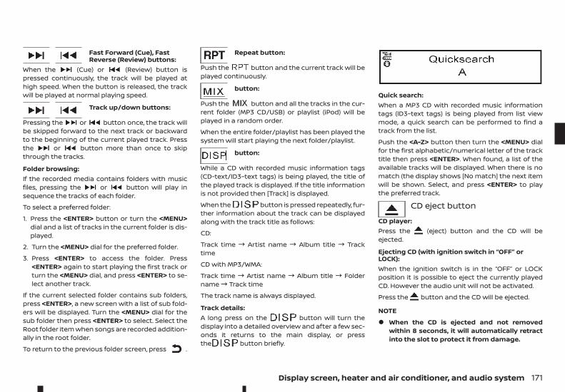
Fast Forward (Cue), FastReverse (Review) buttons:
When the (Cue) or (Review) button ispressed continuously, the track will be played athigh speed. When the button is released, the trackwill be played at normal playing speed.
Track up/down buttons:
Pressing the or button once, the track willbe skipped forward to the next track or backwardto the beginning of the current played track. Pressthe or button more than once to skipthrough the tracks.
Folder browsing:If the recorded media contains folders with musicfiles, pressing the or button will play insequence the tracks of each folder.
To select a preferred folder:
1. Press the <ENTER> button or turn the <MENU>dial and a list of tracks in the current folder is dis-played.
2. Turn the <MENU> dial for the preferred folder.
3. Press <ENTER> to access the folder. Press<ENTER> again to start playing the first track orturn the <MENU> dial, and press <ENTER> to se-lect another track.
If the current selected folder contains sub folders,press <ENTER>, a new screen with a list of sub fold-ers will be displayed. Turn the <MENU> dial for thesub folder then press <ENTER> to select. Select theRoot folder item when songs are recorded addition-ally in the root folder.
To return to the previous folder screen, press .
Repeat button:
Push the button and the current track will beplayed continuously.
button:
Push the button and all the tracks in the cur-rent folder (MP3 CD/USB) or playlist (iPod) will beplayed in a random order.
When the entire folder/playlist has been played thesystem will start playing the next folder/playlist.
button:
While a CD with recorded music information tags(CD-text/ID3–text tags) is being played, the title ofthe played track is displayed. If the title informationis not provided then [Track] is displayed.
When the button is pressed repeatedly, fur-ther information about the track can be displayedalong with the track title as follows:
CD:
Track time ! Artist name ! Album title ! Tracktime
CD with MP3/WMA:
Track time ! Artist name ! Album title ! Foldername! Track time
The track name is always displayed.
Track details:A long press on the button will turn thedisplay into a detailed overview and after a few sec-onds it returns to the main display, or pressthe button briefly.
Quick search:When a MP3 CD with recorded music informationtags (ID3–text tags) is being played from list viewmode, a quick search can be performed to find atrack from the list.
Push the <A-Z> button then turn the <MENU> dialfor the first alphabetic/numerical letter of the tracktitle then press <ENTER>. When found, a list of theavailable tracks will be displayed. When there is nomatch (the display shows [No match] the next itemwill be shown. Select, and press <ENTER> to playthe preferred track.
CD eject button
CD player:Press the (eject) button and the CD will beejected.
Ejecting CD (with ignition switch in “OFF” orLOCK):When the ignition switch is in the “OFF” or LOCKposition it is possible to eject the currently playedCD. However the audio unit will not be activated.
Press the button and the CD will be ejected.
NOTE
• When the CD is ejected and not removedwithin 8 seconds, it will automatically retractinto the slot to protect it from damage.
Display screen, heater and air conditioner, and audio system 171
• If an error message appears in the display,press to eject the faulty CD and insert an-other CD or check if the ejected CD is insertedupside down.
AUX SOCKETAudio main operationThe AUX input jack is located on the lower part ofthe instrument panel. See “AUX (Auxiliary) input jack”earlier in this section. The AUX input jack acceptsany standard analog audio input such as from aportable cassette tape/CD player, MP3 player or lap-top computer.
Push the button to play a compatible devicewhen it is plugged into the AUX input jack.
Renault strongly recommends using a stereo miniplug cable when connecting your music device tothe audio system. Music may not play properly whena monaural cable is used.
WARNINGDo not allow the cable or an external device con-nected to the AUX terminal to affect your driving.
NOTE
• Depending on the external device, please notethat the volume may be louder or quieter thanthat of the external device.
• When the AUX socket first contacts the plug ofthe connector cable, noise may be heard.
• The connected external device cannot be op-erated with the main audio system. The vol-ume and sound quality can be adjusted.
• The song title in the external device cannot bedisplayed on the audio display.
• To power the external device, use an appropri-ate battery. The external device cannot becharged with the AUX terminal. Noise may beheard if the external device is operated whilecharging the battery using the power socketof the vehicle.
USB (Universal Serial Bus)CONNECTION PORT
WARNINGDo not connect, disconnect or operate the USBdevice while driving. Doing so can be a distrac-tion. If distracted you could lose control of yourvehicle and cause an accident or serious injury.
CAUTION• Do not force the USB device into the USB port.
Inserting the USB device tilted or up-side-down into the port may damage the port.Make sure that the USB device is connectedcorrectly into the USB port.
• Do not grab the USB port cover (where fitted)when pulling the USB device out of the port.This could damage the port and the cover.
• Do not leave the USB cable in a place where itcan be pulled unintentionally. Pulling the cablemay damage the port.
General notes for USB use:
Refer to your device manufacturer's owner infor-mation regarding the proper use and care of thedevice.
Connecting USB deviceOpen the console lid and connect a USB memorystick or another USB device. The display will showthe notification message [USB Detected PleaseWait...] for a few seconds, while it is reading the data.If the audio system has been turned off while theUSB memory was playing, pressing will start theUSB device operation.
MEDIA buttonTo operate the USB device press <MEDIA> once orrepeatedly until [USB] is available.
Audio main operationThe following operations are identical to the audiomain operation of the Compact Disc (CD) operation.For details, see “Compact Disc (CD) operation” ear-lier in this section.
• List view
• Quick search
• ,
• MIX (Random play)
• RPT (Repeat track)
• Folder browsing
172 Display screen, heater and air conditioner, and audio system
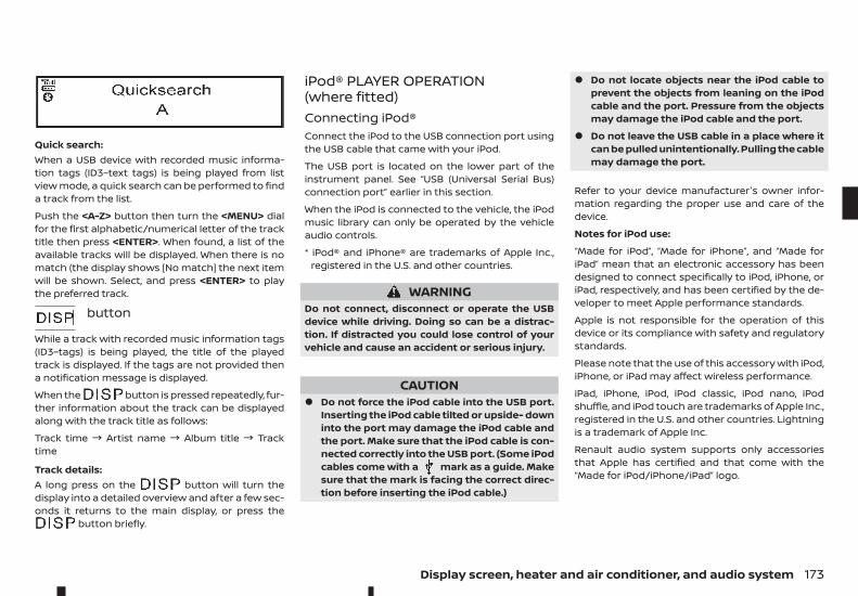
Quick search:When a USB device with recorded music informa-tion tags (ID3–text tags) is being played from listview mode, a quick search can be performed to finda track from the list.
Push the <A-Z> button then turn the <MENU> dialfor the first alphabetic/numerical letter of the tracktitle then press <ENTER>. When found, a list of theavailable tracks will be displayed. When there is nomatch (the display shows [No match] the next itemwill be shown. Select, and press <ENTER> to playthe preferred track.
button
While a track with recorded music information tags(ID3–tags) is being played, the title of the playedtrack is displayed. If the tags are not provided thena notification message is displayed.
When the button is pressed repeatedly, fur-ther information about the track can be displayedalong with the track title as follows:
Track time ! Artist name ! Album title ! Tracktime
Track details:A long press on the button will turn thedisplay into a detailed overview and after a few sec-onds it returns to the main display, or press the
button briefly.
iPod® PLAYER OPERATION(where fitted)Connecting iPod®Connect the iPod to the USB connection port usingthe USB cable that came with your iPod.
The USB port is located on the lower part of theinstrument panel. See “USB (Universal Serial Bus)connection port” earlier in this section.
When the iPod is connected to the vehicle, the iPodmusic library can only be operated by the vehicleaudio controls.
* iPod® and iPhone® are trademarks of Apple Inc.,registered in the U.S. and other countries.
WARNINGDo not connect, disconnect or operate the USBdevice while driving. Doing so can be a distrac-tion. If distracted you could lose control of yourvehicle and cause an accident or serious injury.
CAUTION• Do not force the iPod cable into the USB port.
Inserting the iPod cable tilted or upside- downinto the port may damage the iPod cable andthe port. Make sure that the iPod cable is con-nected correctly into the USB port. (Some iPodcables come with a mark as a guide. Makesure that the mark is facing the correct direc-tion before inserting the iPod cable.)
• Do not locate objects near the iPod cable toprevent the objects from leaning on the iPodcable and the port. Pressure from the objectsmay damage the iPod cable and the port.
• Do not leave the USB cable in a place where itcan be pulled unintentionally. Pulling the cablemay damage the port.
Refer to your device manufacturer's owner infor-mation regarding the proper use and care of thedevice.
Notes for iPod use:
“Made for iPod”, “Made for iPhone”, and “Made foriPad” mean that an electronic accessory has beendesigned to connect specifically to iPod, iPhone, oriPad, respectively, and has been certified by the de-veloper to meet Apple performance standards.
Apple is not responsible for the operation of thisdevice or its compliance with safety and regulatorystandards.
Please note that the use of this accessory with iPod,iPhone, or iPad may affect wireless performance.
iPad, iPhone, iPod, iPod classic, iPod nano, iPodshuffle, and iPod touch are trademarks of Apple Inc.,registered in the U.S. and other countries. Lightningis a trademark of Apple Inc.
Renault audio system supports only accessoriesthat Apple has certified and that come with the“Made for iPod/iPhone/iPad” logo.
Display screen, heater and air conditioner, and audio system 173
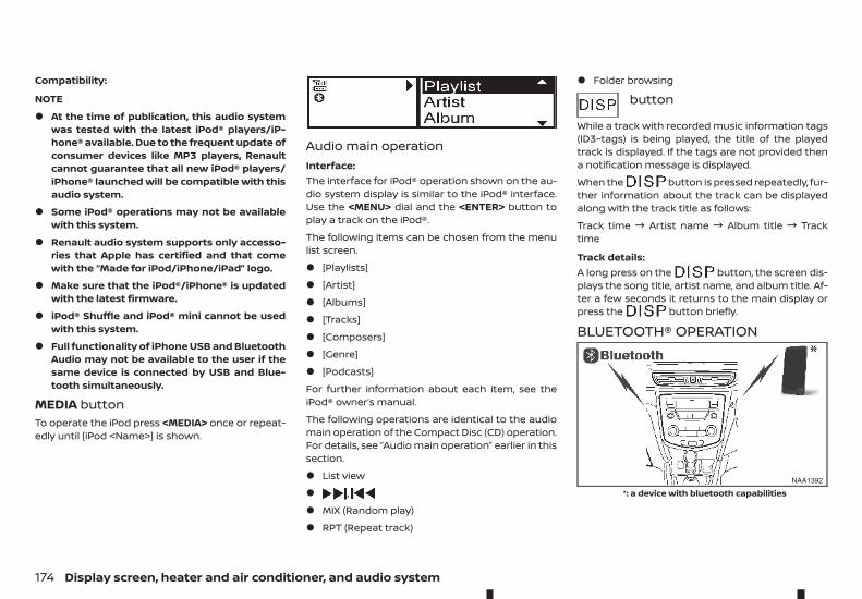
Compatibility:
NOTE
• At the time of publication, this audio systemwas tested with the latest iPod® players/iP-hone® available. Due to the frequent update ofconsumer devices like MP3 players, Renaultcannot guarantee that all new iPod® players/iPhone® launched will be compatible with thisaudio system.
• Some iPod® operations may not be availablewith this system.
• Renault audio system supports only accesso-ries that Apple has certified and that comewith the “Made for iPod/iPhone/iPad” logo.
• Make sure that the iPod®/iPhone® is updatedwith the latest firmware.
• iPod® Shuffle and iPod® mini cannot be usedwith this system.
• Full functionality of iPhone USB and BluetoothAudio may not be available to the user if thesame device is connected by USB and Blue-tooth simultaneously.
MEDIA buttonTo operate the iPod press <MEDIA> once or repeat-edly until [iPod <Name>] is shown.
Audio main operationInterface:The interface for iPod® operation shown on the au-dio system display is similar to the iPod® interface.Use the <MENU> dial and the <ENTER> button toplay a track on the iPod®.
The following items can be chosen from the menulist screen.
• [Playlists]
• [Artist]
• [Albums]
• [Tracks]
• [Composers]
• [Genre]
• [Podcasts]
For further information about each item, see theiPod® owner’s manual.
The following operations are identical to the audiomain operation of the Compact Disc (CD) operation.For details, see “Audio main operation” earlier in thissection.
• List view
• ,
• MIX (Random play)
• RPT (Repeat track)
• Folder browsing
button
While a track with recorded music information tags(ID3–tags) is being played, the title of the playedtrack is displayed. If the tags are not provided thena notification message is displayed.
When the button is pressed repeatedly, fur-ther information about the track can be displayedalong with the track title as follows:
Track time ! Artist name ! Album title ! Tracktime
Track details:A long press on the button, the screen dis-plays the song title, artist name, and album title. Af-ter a few seconds it returns to the main display orpress the button briefly.
BLUETOOTH® OPERATION
NAA1392
*: a device with bluetooth capabilities
174 Display screen, heater and air conditioner, and audio system
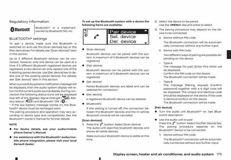
Regulatory information
mBluetooth® is a trademarkowned by Bluetooth SIG, Inc.
BLUETOOTH® settingsTo pair a device, make sure the Bluetooth isswitched on and use the [Scan devices] key or the[Pair device] key. For details, see “[Scan devices]” laterin this section.
Up to 5 different Bluetooth devices can be con-nected. However, only one device can be used at atime. If 5 different Bluetooth registered devices areregistered, a new device can only replace one of the5 existing paired devices. Use [Del. device] key to de-lete one of the existing paired devices. For details,see “[Del. device]” later in this section.
When successfully paired a notification message willbe displayed, then the audio system display will re-turn to the current audio source display. During con-nection the following status icons will be displayed(top left of the display): Signal strength ( ), Bat-tery status* ( ) and Bluetooth “ON” ( ).*: If the low battery message comes on, the Blue-tooth® device must be recharged soon.The pairing procedure and operation may vary ac-cording to device type and compatibility. See theBluetooth® owner’s manual for further details.
NOTE
• For device details, see your audio/mobilephone Owner's Manual.
• For assistance with the Bluetooth® audio/mo-bile phone integration, please visit your localRenault dealer.
To set up the Bluetooth system with a device thefollowing items are available:
• [Scan devices]
Bluetooth devices can be paired with the sys-tem. A maximum of 5 Bluetooth devices can beregistered.
• [Pair device]
Bluetooth devices can be paired with the sys-tem. A maximum of 5 Bluetooth devices can beregistered.
• [Sel. device]
Paired Bluetooth devices are listed and can beselected for connection.
• [Del. device]
A registered Bluetooth device can be deleted.
• [Bluetooth]
If this setting is turned off, the connection be-tween the Bluetooth devices and the in-vehicleBluetooth module will be cancelled.
[Scan devices]:1) Press the button. Select [Scan device]
The audio unit searches bluetooth devices andshows all visible devices.
Make sure your Bluetooth device is visible at thistime.
2) Select the device to be paired.Use the <MENU> dial and press to select.
3) The pairing procedure may depend on the de-vice to be connected:
a. Device without PIN code:
The Bluetooth connection will be automati-cally connected without any further input.
b. Device with PIN code:
Two different ways of pairing are possible de-pending on the device:
– Type A:The message [To pair] [Enter Pin] 0000 willbe displayed.Confirm the PIN code on the device.The Bluetooth connection will be made.
– Type B:The message [Pairing request] [Confirmpassword] together with a 6 digit code willbe displayed. The unique and identical codeshould be displayed on the device. If the codeis identical confirm on the device.The Bluetooth connection will be made.
[Pair device]:• Turn the audio unit Bluetooth® on. See [Blue-
tooth] description.
• Use the audio unit to pair:Press the button. Select the [Pair Device] key.The pairing procedure depends on theBluetooth® device to be connected:
1) Device without PIN code:
The Bluetooth® connection will be automati-cally connected without any further input.
Display screen, heater and air conditioner, and audio system 175
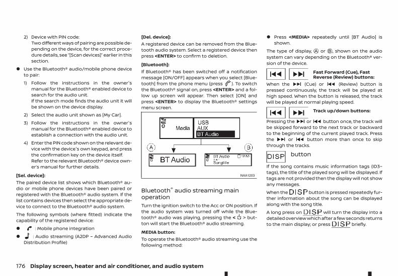
2) Device with PIN code:Two different ways of pairing are possible de-pending on the device, for the correct proce-dure details, see “[Scan devices]” earlier in thissection.
• Use the Bluetooth® audio/mobile phone deviceto pair:
1) Follow the instructions in the owner'smanual for the Bluetooth® enabled device tosearch for the audio unit.If the search mode finds the audio unit it willbe shown on the device display.
2) Select the audio unit shown as [My Car].
3) Follow the instructions in the owner'smanual for the Bluetooth® enabled device toestablish a connection with the audio unit.
4) Enter the PIN code shown on the relevant de-vice with the device's own keypad, and pressthe confirmation key on the device itself.Refer to the relevant Bluetooth® device own-er’s manual for further details.
[Sel. device]:The paired device list shows which Bluetooth® au-dio or mobile phone devices have been paired orregistered with the Bluetooth® audio system. If thelist contains devices then select the appropriate de-vice to connect to the Bluetooth® audio system.
The following symbols (where fitted) indicate thecapability of the registered device:
• : Mobile phone integration
• : Audio streaming (A2DP – Advanced AudioDistribution Profile)
[Del. device]:A registered device can be removed from the Blue-tooth audio system. Select a registered device thenpress <ENTER> to confirm to deletion.
[Bluetooth]:If Bluetooth® has been switched off a notificationmessage [ON/OFF] appears when you select [Blue-tooth] from the phone menu (press ). To switchthe Bluetooth® signal on, press <ENTER> and a fol-low up screen will appear. Then select [ON] andpress <ENTER> to display the Bluetooth® settingsmenu screen.
Bluetooth® audio streaming mainoperationTurn the ignition switch to the Acc or ON position. Ifthe audio system was turned off while the Blue-tooth® audio was playing, pressing the < > but-ton will start the Bluetooth® audio streaming.
MEDIA button:To operate the Bluetooth® audio streaming use thefollowing method:
• Press <MEDIA> repeatedly until [BT Audio] isshown.
The type of display, jA or jB , shown on the audiosystem can vary depending on the Bluetooth® ver-sion of the device.
Fast Forward (Cue), FastReverse (Review) buttons:
When the (Cue) or (Review) button ispressed continuously, the track will be played athigh speed. When the button is released, the trackwill be played at normal playing speed.
Track up/down buttons:
Pressing the or button once, the track willbe skipped forward to the next track or backwardto the beginning of the current played track. Pressthe or button more than once to skipthrough the tracks.
button
If the song contains music information tags (ID3–tags), the title of the played song will be displayed. Iftags are not provided then the display will not showany messages.
When the button is pressed repeatedly fur-ther information about the song can be displayedalong with the song title.
A long press on will turn the display into adetailed overview which after a few seconds returnsto the main display; or press briefly.
NAA1203
176 Display screen, heater and air conditioner, and audio system
Bluetooth® mobile phone featureThis system offers a hands-free facility for your mo-bile telephone with Bluetooth® to enhance drivingsafety, and comfort.For details, see “Bluetooth® operation” later in thissection.
Display screen, heater and air conditioner, and audio system 177

Specification chart
Supported media CD-R, CD-ROM, CD-RW, USB 2.0 MSC
CD Size 12 cm diameter. up to 1.9 mm thickness
Supported file systems for CD ISO9660 LEVEL1, ISO9660 LEVEL2, Romeo, Joliet* ISO9660 Level 3 (packet writing) is not supported.* Files saved using the Live File System Component (on a Windows Vista-basedcomputer) are not supported.
Supported file systems for USB FAT-16, FAT-32
Supported versions *1 MP3 Version MPEG1, Layer 3
Sampling frequency 32 KHz - 44.1 KHz - 48 kHz
Bit rate 32, 40, 48, 56, 64, 80, 96, 112, 128, 144, 160, 192, 224, 256, 288, 320, Kbps, VBR *4
WMA *3 Version WMA7, WMA8, WMA9
Sampling frequency 16 KHz, 22.05 KHz, 32 KHz, 44.1KHz, 48 kHz
Bit rate 48, 64, 80, 96, 128, 160, 192, 256, 320 Kbps, VBR *4
AAC Version MPEG-4, AAC
Sampling frequency 8, 11.025, 16, 22.05, 32, 44.1, 48 kHz
Bit rate 32, 48, 64, 80, 96, 128, 160, 192 Kbps, VBR *4
Tag information (Song title and Artistand Album name)
CD CDDA
MP3 ID3 tag ver. 1.0, 1.1, 2.2, 2.4
WMA WMA tag
AAC AAC tag
Tracks/Files support CDDA — 99 tracksMP3/WMA/AAC in CD — 999 filesUSB — 30000 files
Folders support 1024 folders in CD2500 folders in USBDepth — Till 8, Deeper folders shall be under 8, subject to the maximum.
Playlists support in USB M3U, WPL, PLS — 1000 playlists.
178 Display screen, heater and air conditioner, and audio system

Text character support Adjustable character length,depending upon content ofmedia.
File Name: Min 11 Characters ( Max 30 Characters) ID3 TAG : Min 24 Characters.(Max 60 Characters) *5
Displayable character codes *2 Unicode, ISO8859–15(French),ISO8859–5(Russian Cyrillic),GB18030–2000(Chinese), BIG-5(Taiwanese), KSX1001–2002(Korean)
01:ASCll, 02: ISO-8859-1, ISO8859–15(French), ISO8859–5(Russian Cyrillic), 03:UNICODE(UTF-16 BOM Big Endian), 04: UNICODE (UTF-16 Ncn-BOM Big Endian), 05:UNICODE(UTF-8), 06:UNICODE(Non-UTF-16 BOM Little Endian), 07: SHIFT-JIS,GB18030–2000(Chinese), BIG-5(Taiwanese), KSX1001–2002(Korean)
Browsing File/Folder browsing for CD/MP3, USB
*1 Files created with a combination of 48 kHz sampling frequency and 64 Kbps bit rate cannot be played.*2 Available codes depend on what kind of media, versions and information are going to be displayed.*3 Protected WMA files (DRM) cannot be played.*4 When VBR files are played, the playback time may not be displayed correctly. WMA7 and WMA8 are not applied to VBR.*5 Support 128 Bytes but it depends on display width and character type.
Display screen, heater and air conditioner, and audio system 179
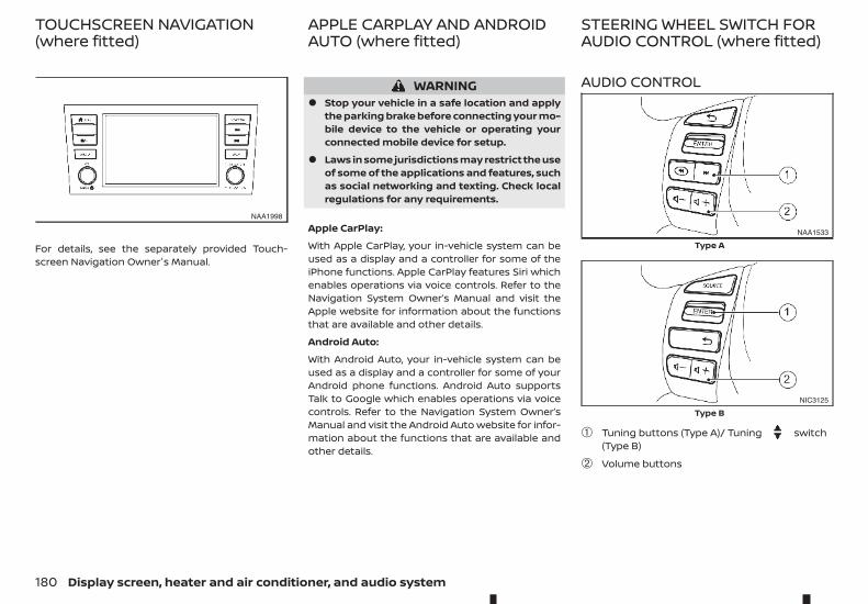
For details, see the separately provided Touch-screen Navigation Owner's Manual.
WARNING• Stop your vehicle in a safe location and apply
the parking brake before connecting your mo-bile device to the vehicle or operating yourconnected mobile device for setup.
• Laws in some jurisdictions may restrict the useof some of the applications and features, suchas social networking and texting. Check localregulations for any requirements.
Apple CarPlay:
With Apple CarPlay, your in-vehicle system can beused as a display and a controller for some of theiPhone functions. Apple CarPlay features Siri whichenables operations via voice controls. Refer to theNavigation System Owner’s Manual and visit theApple website for information about the functionsthat are available and other details.
Android Auto:
With Android Auto, your in-vehicle system can beused as a display and a controller for some of yourAndroid phone functions. Android Auto supportsTalk to Google which enables operations via voicecontrols. Refer to the Navigation System Owner’sManual and visit the Android Auto website for infor-mation about the functions that are available andother details.
AUDIO CONTROL
➀ Tuning buttons (Type A)/ Tuning switch(Type B)
➁ Volume buttons
NAA1998
NAA1533
Type A
NIC3125
Type B
TOUCHSCREEN NAVIGATION(where fitted)
APPLE CARPLAY AND ANDROIDAUTO (where fitted)
STEERING WHEEL SWITCH FORAUDIO CONTROL (where fitted)
180 Display screen, heater and air conditioner, and audio system
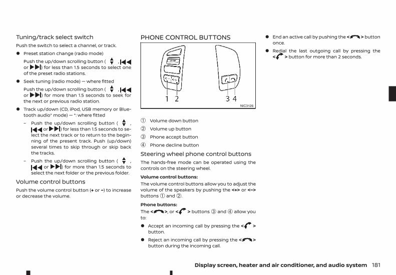
Tuning/track select switchPush the switch to select a channel, or track.
• Preset station change (radio mode)
Push the up/down scrolling button ( ,or ) for less than 1.5 seconds to select oneof the preset radio stations.
• Seek tuning (radio mode) — where fitted
Push the up/down scrolling button ( ,or ) for more than 1.5 seconds to seek forthe next or previous radio station.
• Track up/down (CD, iPod, USB memory or Blue-tooth audio* mode) — *: where fitted
– Push the up/down scrolling button ( ,or ) for less than 1.5 seconds to se-
lect the next track or to return to the begin-ning of the present track. Push (up/down)several times to skip through or skip backthe tracks.
– Push the up/down scrolling button ( ,or ) for more than 1.5 seconds to
select the next folder or the previous folder.
Volume control buttonsPush the volume control button (+ or −) to increaseor decrease the volume.
PHONE CONTROL BUTTONS
➀ Volume down button
➁ Volume up button
➂ Phone accept button
➃ Phone decline button
Steering wheel phone control buttonsThe hands-free mode can be operated using thecontrols on the steering wheel.
Volume control buttons:The volume control buttons allow you to adjust thevolume of the speakers by pushing the <+> or <−>buttons ➀ and ➁.
Phone buttons:The < >, or < > buttons ➂ and ➃ allow youto:
• Accept an incoming call by pressing the < >button.
• Reject an incoming call by pressing the < >button during the incoming call.
• End an active call by pushing the < > buttononce.
• Redial the last outgoing call by pressing the< > button for more than 2 seconds.
NIC3126
Display screen, heater and air conditioner, and audio system 181
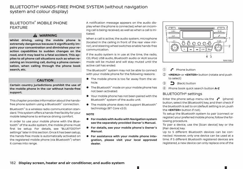
BLUETOOTH® MOBILE PHONEFEATURE
WARNINGWhilst driving, using the mobile phone isextremely dangerous because it significantly im-pairs your concentration and diminishes your re-action capabilities to sudden changes on theroad, and it may lead to a fatal accident. This ap-plies to all phone call situations such as when re-ceiving an incoming call, during a phone conver-sation, when calling through the phone booksearch, etc.
CAUTIONCertain country jurisdictions prohibit the use ofthe mobile phone in the car without hands-freesupport.
This chapter provides information about the hands-free phone system using a Bluetooth® connection.
Bluetooth® is a wireless radio communication stan-dard. This system offers a hands-free facility for yourmobile telephone to enhance driving comfort.
In order to use your mobile phone with the Blue-tooth® of the audio system, the mobile phone mustfirst be setup. For details, see “BLUETOOTH®settings” later in this section. Once it has been setup,the hands-free mode is automatically activated onthe registered mobile phone (via Bluetooth®) whenit comes into range.
A notification message appears on the audio dis-play when the phone is connected, when an incom-ing call is being received, as well as when a call is ini-tiated.
When a call is active, the audio system, microphone(located in the ceiling in front of the rear view mir-ror), and steering wheel switches enable hands-freecommunication.
If the audio system is in use at the time, the radio,CD, iPod, USB audio, Bluetooth audio or AUX sourcemode will be muted and will stay muted until theactive call has ended.
The Bluetooth® system may not be able to connectwith your mobile phone for the following reasons:
• The mobile phone is too far away from the ve-hicle.
• The Bluetooth® mode on your mobile phone hasnot been activated.
• Your mobile phone has not been paired with theBluetooth® system of the audio unit.
• The mobile phone does not support Bluetooth®
technology (BT Core v2.0).
NOTE
• For models with Audio with Navigation systemsee the separately provided Owner's Manual.
• For details, see your mobile phone's Owner'sManual.
• For assistance with your mobile phone inte-gration, please visit your local approveddealer.
➀ Phone button
➁ <MENU> or <ENTER> button (rotate and pushto select)
➂ (Back) button
➃ Phone book quick search button A-Z
BLUETOOTH® settingsEnter the phone setup menu via the (phone)button, select the [Bluetooth] key, and then check ifthe bluetooth is set to on (default setting is on, pushthe <ENTER> button if not).To setup the Bluetooth system to pair (connect orregister) your preferred mobile phone, follow the fol-lowing procedure.To pair a device, use the [Scan device] key or the[Pair device] key.Up to 5 different Bluetooth devices can be con-nected. However, only one device can be used at atime. If 5 different Bluetooth registered devices areregistered, a new device can only replace one of the
NAA1582
BLUETOOTH® HANDS-FREE PHONE SYSTEM (without navigationsystem and colour display)
182 Display screen, heater and air conditioner, and audio system
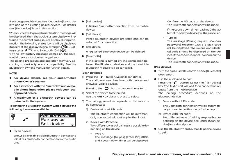
5 existing paired devices. Use [Del. device] key to de-lete one of the existing paired devices. For details,see “[Del. device]” later in this section.
When successfully paired a notification message willbe displayed, then the audio system display will re-turn to the current audio source display. During con-nection the following status icons will be displayed(top left of the display): Signal strength ( ), Bat-tery status* ( ) and Bluetooth “ON” ( ).*: If the low battery message comes on, the Blue-tooth® device must be recharged soon.The pairing procedure and operation may vary ac-cording to device type and compatibility. See theBluetooth® owner’s manual for further details.
NOTE
• For device details, see your audio/mobilephone Owner's Manual.
• For assistance with the Bluetooth® audio/mo-bile phone integration, please visit your localapproved dealer.
• A maximum of 5 Bluetooth devices can bepaired with the system.
To set up the Bluetooth system with a device thefollowing items are available:
• [Scan devices]
Shows all available visible Bluetooth devices andinitializes Bluetooth connection from the audiounit.
• [Pair device]
Initializes Bluetooth connection from the mobiledevice.
• [Sel. device]
Paired Bluetooth devices are listed and can beselected for connection.
• [Del. device]
A registered Bluetooth device can be deleted.
• [Bluetooth]
If this setting is turned off, the connection be-tween the Bluetooth devices and the in-vehicleBluetooth module will be cancelled.
[Scan devices]:1) Press the button. Select [Scan device]
The audio unit searches bluetooth devices andshows all visible devices.
Pressing the button cancels the search.
2) Select the device to be paired.Use the <MENU> dial and press to select.
3) The pairing procedure depends on the device tobe connected:
1) Device without PIN code:
The Bluetooth connection will be automati-cally connected without any further input.
2) Device with PIN code:Two different ways of pairing are possible de-pending on the device:
– Type A:The message [To pair] [Enter Pin] 0000and a count down timer will be displayed.
Confirm the PIN code on the device.The Bluetooth connection will be made.
If the count down timer reaches 0 the at-tempt to pair the devices will be cancelled.
– Type B:The message [Pairing request] [Confirmpassword] together with a 6 digit codewill be displayed. The unique and identi-cal code should be displayed on the de-vice. If the code is identical confirm on thedevice.The Bluetooth connection will be made.
[Pair device]:• Turn the audio unit Bluetooth on. See [Bluetooth]
description.
• Use the audio unit to pair:Press the button. Select the [Pair device]key. The Audio unit will wait for a connection re-quest from the mobile device.The pairing procedure depends on theBluetooth device:
1) Device without PIN code:
The Bluetooth connection will be automati-cally connected without any further input.
2) Device with PIN code:Two different ways of pairing are possible de-pending on the device, see under [Scan de-vice] for a description.
• Use the Bluetooth® audio/mobile phone deviceto pair:
Display screen, heater and air conditioner, and audio system 183
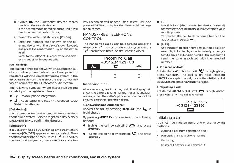
1) Switch ON the Bluetooth® devices searchmode on the mobile device.If the search mode finds the audio unit it willbe shown on the device display.
2) Select the audio unit shown as [My Car].
3) Enter the number code shown on the rel-evant device with the device's own keypad,and press the confirmation key on the deviceitself.Refer to the relevant Bluetooth® device own-er’s manual for further details.
[Sel. device]:The paired device list shows which Bluetooth® au-dio or mobile phone devices have been paired orregistered with the Bluetooth® audio system. If thelist contains devices then select the appropriate de-vice to connect to the Bluetooth® audio system.
The following symbols (where fitted) indicate thecapability of the registered device:
• : Mobile phone integration
• : Audio streaming (A2DP – Advanced AudioDistribution Profile)
[Del. device]:A registered device can be removed from the Blue-tooth audio system. Select a registered device thenpress <ENTER> to confirm the deletion.
[Bluetooth]:If Bluetooth® has been switched off a notificationmessage [ON/OFF] appears when you select [Blue-tooth] from the phone menu (press ). To switchthe Bluetooth® signal on, press <ENTER> and a fol-
low up screen will appear. Then select [ON] andpress <ENTER> to display the Bluetooth® settingsmenu screen.
HANDS-FREE TELEPHONECONTROLThe hands-free mode can be operated using thetelephone button on the audio system, or the
and (where fitted) on the steering wheel.
Receiving a callWhen receiving an incoming call, the display willshow the caller's phone number (or a notificationmessage that the caller's phone number cannot beshown) and three operation icons.
1. Answering and during a call:Answer the call by pressing <ENTER> (the ishighlighted).
By pressing <ENTER>, you can select the followingoptions:
• Ending the call by selecting and press<ENTER>.
• Put the call on hold by selecting and press<ENTER>.
• [ ]Use this item (the transfer handset command)to transfer the call from the audio system to yourmobile phone.To transfer the call back to hands-free via theaudio system select [ ].
• [#123]Use this item to enter numbers during a call. Forexample, if directed by an automated phone sys-tem to dial an extension number the system willsend the tone associated with the selectednumber.
2. Put a call on hold:Rotate the <MENU> dial until is highlighted,press <ENTER>. The call is on hold. Pressing<ENTER> accepts the call, rotate the <MENU> dialclockwise and press <ENTER> to reject.
3. Rejecting a call:Rotate the <MENU> dial until is highlighted,press <ENTER>. The call is rejected.
Initiating a callA call can be initiated using one of the followingmethods:
– Making a call from the phone book
– Manually dialling a phone number
– Redialling
– Using call history (Call List menu)
184 Display screen, heater and air conditioner, and audio system
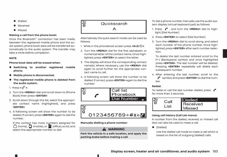
• Dialled
• Received
• Missed
Making a call from the phone book:Once the Bluetooth® connection has been made,between the registered mobile phone and the au-dio system, phone book data will be transferred au-tomatically to the audio system. The transfer maytake a while before completion.
NOTE
Phone book data will be erased when:
• Switching to another registered mobilephone.
• Mobile phone is disconnected.
• The registered mobile phone is deleted fromthe audio system.
1. Press < >.
2. Turn the <MENU> dial and scroll down to [PhoneBook] then press <ENTER>.
3. Scroll down through the list, select the appropri-ate contact name (highlighted), and press<ENTER>.
4. A following screen will show the number to bedialled. If correct, press <ENTER> again to dial thenumber.
If the contact has more numbers assigned for(home), (mobile), or (office), scroll, and
select the appropriate number to dial.
Alternatively, the quick search mode can be used asfollows:
1. While in the phonebook screen press <A-Z/➅>.
2. Turn the <MENU> dial for the first alphabetic ornumerical letter of the contact name. Once high-lighted, press <ENTER> to select the letter.
3. The display will show the corresponding contactname(s). Where necessary, use the <MENU> dialagain to scroll further for the appropriate con-tact name to call.
4. A following screen will show the number to bedialled. If correct, press <ENTER> again to dial thenumber.
Manually dialling a phone number:
WARNINGPark the vehicle in a safe location, and apply theparking brake before making a call.
To dial a phone number manually use the audio sys-tem display (virtual keyboard pad) as follows:
1. Press , and turn the <MENU> dial to high-light [Dial Number].
2. Press <ENTER> to select [Dial Number].
3. Turn the <MENU> dial to scroll along, and selecteach number of the phone number. Once high-lighted, press <ENTER> after each number selec-tion.
To delete the last number entered scroll to the["] (Backspace) symbol, and once highlightedpress <ENTER>. The last number will be deleted.Pressing <ENTER> repeatedly will delete eachsubsequent number.
4. After entering the last number, scroll to thesymbol, and press <ENTER> to dial the num-
ber.
Redial:To redial or call the last number dialled, pressfor more than 2 seconds.
Using call history (Call List menu):A number from the dialled, received, or missed calllists can also be used to make a call.
• [Dialled]
Use the dialled call mode to make a call which isbased on the list of outgoing (dialled) calls.
Display screen, heater and air conditioner, and audio system 185
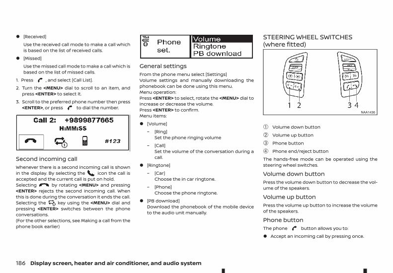
• [Received]
Use the received call mode to make a call whichis based on the list of received calls.
• [Missed]
Use the missed call mode to make a call which isbased on the list of missed calls.
1. Press , and select [Call List].
2. Turn the <MENU> dial to scroll to an item, andpress <ENTER> to select it.
3. Scroll to the preferred phone number then press<ENTER>, or press to dial the number.
Second incoming callWhenever there is a second incoming call is shownin the display. By selecting the icon the call isaccepted and the current call is put on hold.Selecting by rotating <MENU> and pressing<ENTER> rejects the second incoming call. Whenthis is done during the conversation it ends the call.Selecting the key using the <MENU> dial andpressing <ENTER> switches between the phoneconversations.(For the other selections, see Making a call from thephone book earlier)
General settingsFrom the phone menu select [Settings]Volume settings and manually downloading thephonebook can be done using this menu.Menu operation:Press <ENTER> to select, rotate the <MENU> dial toincrease or decrease the volume.Press <ENTER> to confirm.Menu items:
• [Volume]
– [Ring]Set the phone ringing volume
– [Call]Set the volume of the conversation during acall.
• [Ringtone]
– [Car]Choose the in car ringtone.
– [Phone]Choose the phone ringtone.
• [PB download]Download the phonebook of the mobile deviceto the audio unit manually.
STEERING WHEEL SWITCHES(where fitted)
➀ Volume down button
➁ Volume up button
➂ Phone button
➃ Phone end/reject button
The hands-free mode can be operated using thesteering wheel switches.
Volume down buttonPress the volume down button to decrease the vol-ume of the speakers.
Volume up buttonPress the volume up button to increase the volumeof the speakers.
Phone buttonThe phone button allows you to:
• Accept an incoming call by pressing once.
NAA1436
186 Display screen, heater and air conditioner, and audio system
• Redial the last outgoing call by pressing the but-ton for more than 2 seconds.
Phone END button• Reject an incoming call by pressing during
an incoming call.
• End an active call by pressing once.
Display screen, heater and air conditioner, and audio system 187
NOTE
188 Display screen, heater and air conditioner, and audio system
5 Starting and drivingStarting and driving
Running-in schedule ................................................................................. 191Before starting engine............................................................................. 191Precautions when starting and driving...................................... 191
Exhaust gas (carbon monoxide) .............................................. 192AdBlue® Selective Catalytic Reduction (SCR)system.......................................................................................................... 192
Diesel Particulate Filter (DPF) (where fitted) ............................ 197Automatic regeneration................................................................. 197
On-road and off-road driving precautions............................... 198Driving safety precautions............................................................ 198
Turbocharger system............................................................................... 199Care when driving .......................................................................................200
Engine cold start period.................................................................200Loading luggage ..................................................................................200Driving in wet conditions ...............................................................200Driving in winter conditions.........................................................200
Ignition switch (models without Remote ControlKey system) ......................................................................................................200
Manual Transmission (MT) ............................................................200Automatic Transmission (AT) ......................................................200Key positions........................................................................................... 201Steering lock............................................................................................ 201
Push-button ignition switch (models with RemoteControl Key system)................................................................................... 201
Precautions on push-button ignition switchoperation.................................................................................................... 201Remote Control Key system........................................................ 201Automatic Transmission (AT) ...................................................... 202Steering lock............................................................................................ 202Ignition switch positions................................................................ 203Remote Control Key battery discharge.............................. 203
Starting engine (models without Remote ControlKey system) ...................................................................................................... 204Starting engine (models with Remote Control Keysystem) ................................................................................................................ 204Driving the vehicle....................................................................................... 205
Driving with Automatic Transmission (AT)........................ 205Driving with Manual Transmission (MT).............................. 208
Stop/Start System (where fitted) .................................................... 209Stop/Start System display............................................................ 210Stop/Start OFF switch..................................................................... 211
Four-Wheel Drive (4WD) (where fitted) ......................................... 212Part time 4WD system...................................................................... 2134WD mode switch operation ...................................................... 2164WD mode indicator.......................................................................... 2164WD warning........................................................................................... 217Tyre recommendation for 4WD................................................. 218
Rear differential locking system (where fitted) ..................... 218Electronic Stability Programme (ESP) system(where fitted)................................................................................................... 219
Trailer Sway Assist (TSA) system (where fitted) ............ 220Electronic Stability Programme (ESP) OFFswitch ........................................................................................................... 221
Active Emergency Braking system (where fitted) ............... 221System operation ................................................................................ 221
Hill descent control system (where fitted) ................................ 224Hill descent control switch ........................................................... 224
Hill start assist system (where fitted) ........................................... 225Cruise control (where fitted)................................................................ 225
Precautions on cruise control.................................................... 226Cruise control operations.............................................................. 226
Speed limiter (where fitted).................................................................. 227Speed limiter operations................................................................ 228
ECO drive report ........................................................................................... 229Parking................................................................................................................. 230Parking sensor (sonar) system (where fitted) ........................ 231
Parking sensor (sonar) system OFF switch...................... 232Parking sensor (sonar) system settings............................. 233
Trailer towing .................................................................................................. 233Operating precautions .................................................................... 233Tyre pressure........................................................................................... 233Safety chains........................................................................................... 233Trailer brakes........................................................................................... 234Trailer detection (where fitted).................................................. 234
Vehicle security ............................................................................................. 234
Power steering system............................................................................ 234Brake system................................................................................................... 235
Brake precautions............................................................................... 235Anti-lock Braking System (ABS) ................................................ 235
Cold weather driving................................................................................. 236Battery ......................................................................................................... 237Engine coolant....................................................................................... 237Tyre equipment..................................................................................... 237Special winter equipment............................................................. 237Parking brake.......................................................................................... 237Corrosion protection ........................................................................ 237
During the first 1,600 km (1,000 miles), follow theserecommendations to obtain maximum engine per-formance and ensure the future reliability andeconomy of your new vehicle. Failure to follow theserecommendations may result in shortened enginelife and reduced engine performance.
• Do not drive at a constant speed, either fast orslow, for long periods of time.
• Do not run the engine over 4,000 rpm.
• Do not accelerate at full throttle in any gear.
• Do not start quickly.
• Do not brake hard as much as possible.
• Do not tow a trailer for at least the first 800 km(500 miles).
WARNINGThe driving characteristics of your vehicle willchange remarkably by any additional load and itsdistribution, as well as by adding optional equip-ment (trailer coupling, roof rail, etc.). Your drivingstyle and speed must be adjusted according tothe circumstances. Especially when carryingheavy loads, your speed must be reducedadequately.
• Make sure the area around the vehicle is clear.
• Check fluid levels such as engine oil, coolant,brake (and clutch) fluid, window washer fluid asfrequently as possible, at least whenever you re-fuel.
• Visually inspect tyres for their appearance andcondition. Measure and check the tyre pressurefor proper inflation.
• Check that all windows and lights are clean.
• Adjust the seat and head restraint positions.
• Adjust the inside and outside rearview mirrorpositions.
• Fasten your seat belt and ask all passengers todo the same.
• Check that all doors are closed.
• Check the operation of the warning lights whenthe ignition switch is placed in the “ON” position.
• Maintenance items in the “8. Maintenance anddo-it-yourself” section should be checked peri-odically.
WARNING• Never leave children or adults who would nor-
mally require the support of others alone inyour vehicle. Pets should not be left alone ei-ther. They could unknowingly activateswitches or controls, or move the vehicle, andinadvertently become involved in a serious ac-cident and injure themselves. On hot, sunnydays, temperatures in a closed vehicle couldquickly become high enough to cause severeor possibly fatal illness to people or animals.
• Properly secure all cargo to help prevent itfrom sliding or shifting. Do not place cargohigher than the seatbacks. In a sudden stop orcollision, unsecured cargo could causepersonal injury.
NOTE
During the first few months after purchasing anew vehicle, if you smell strong odours of VolatileOrganic Compounds (VOCs) inside the vehicle,ventilate the passenger compartment thor-oughly. Open all the windows before entering orwhile in the vehicle. In addition, when the tem-perature in the passenger compartment rises, orwhen the vehicle is parked in direct sunlight for aperiod of time, turn off the air recirculation modeof the air conditioner and/or open the windowsto allow sufficient fresh air into the passengercompartment.
RUNNING-IN SCHEDULE BEFORE STARTING ENGINE PRECAUTIONS WHEN STARTINGAND DRIVING
Starting and driving 191
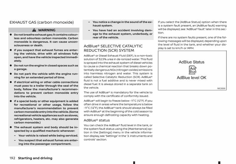
EXHAUST GAS (carbon monoxide)
WARNING• Do not breathe exhaust gas; it contains colour-
less and odourless carbon monoxide. Carbonmonoxide is dangerous. It can cause uncon-sciousness or death.
• If you suspect that exhaust fumes are enter-ing the vehicle, drive with all windows fullyopen, and have the vehicle inspected immedi-ately.
• Do not run the engine in closed spaces such asa garage.
• Do not park the vehicle with the engine run-ning for an extended period of time.
• If electrical wiring or other cable connectionsmust pass to a trailer through the seal of thebody, follow the manufacturer’s recommen-dations to prevent carbon monoxide entryinto the vehicle.
• If a special body or other equipment is addedfor recreational or other usage, follow themanufacturer’s recommendation to preventcarbon monoxide entry into the vehicle. (Somerecreational vehicle appliances such as stoves,refrigerators, heaters, etc. may also generatecarbon monoxide.)
• The exhaust system and body should be in-spected by a qualified mechanic whenever:
– Your vehicle is raised while being serviced.
– You suspect that exhaust fumes are enter-ing into the passenger compartment.
– You notice a change in the sound of the ex-haust system.
– You have had an accident involving dam-age to the exhaust system, underbody, orrear of the vehicle.
AdBlue® SELECTIVE CATALYTICREDUCTION (SCR) SYSTEMAdBlue® or Diesel Exhaust Fluid (DEF), is a non-toxicsolution of 32.5% urea in de-ionized water. This fluidis sprayed into the exhaust system of diesel vehiclesto cause a chemical reaction that breaks down po-tentially dangerous NOx (nitrogen oxides) emissionsinto harmless nitrogen and water. This system iscalled Selective Catalytic Reduction (SCR). AdBlue®fluid is not a fuel additive and is never mixed withdiesel fuel. It is always stored in a separate tank onthe vehicle.
The use of AdBlue® is mandatory for the vehicle tocomply with the certificate of conformity issued.
AdBlue® will begin to freeze below -11°C (12°F). If youoften drive in areas where the temperature is below-11°C (12°F), the AdBlue® tank should always be filledwith AdBlue® at the beginning of the cold season toensure enough defrosting capacity with heating.
AdBlue® statusYou can check the AdBlue® fluid level in the tank, orthe system fault status using the [Maintenance] op-tion in the [Settings] menu in the vehicle informa-tion display, see “Settings” in the “2. Instruments andcontrols” section.
If you select the [AdBlue Status] option when thereis a system fault present, an [AdBlue fault] warningwill be displayed, see “AdBlue® fault” later in this sec-tion.
If there are no system faults present, one of the fol-lowing messages will be displayed, depending uponthe level of fluid in the tank, and whether your dis-play is set to km/h or MPH:
NIC3530
192 Starting and driving
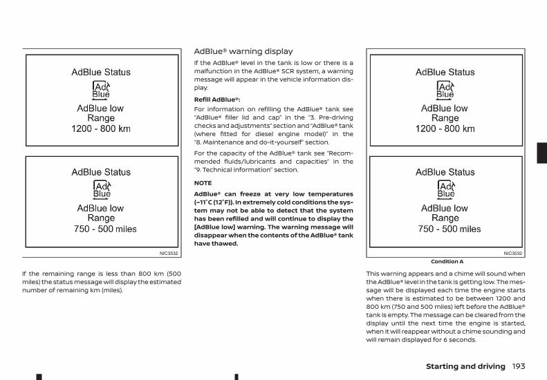
If the remaining range is less than 800 km (500miles) the status message will display the estimatednumber of remaining km (miles).
AdBlue® warning displayIf the AdBlue® level in the tank is low or there is amalfunction in the AdBlue® SCR system, a warningmessage will appear in the vehicle information dis-play.
Refill AdBlue®:For information on refilling the AdBlue® tank see“AdBlue® filler lid and cap” in the “3. Pre-drivingchecks and adjustments” section and “AdBlue® tank(where fitted for diesel engine model)” in the“8. Maintenance and do-it-yourself” section.
For the capacity of the AdBlue® tank see “Recom-mended fluids/lubricants and capacities” in the“9. Technical information” section.
NOTE
AdBlue® can freeze at very low temperatures(–11°C (12°F)). In extremely cold conditions the sys-tem may not be able to detect that the systemhas been refilled and will continue to display the[AdBlue low] warning. The warning message willdisappear when the contents of the AdBlue® tankhave thawed.
This warning appears and a chime will sound whenthe AdBlue® level in the tank is getting low. The mes-sage will be displayed each time the engine startswhen there is estimated to be between 1200 and800 km (750 and 500 miles) left before the AdBlue®tank is empty. The message can be cleared from thedisplay until the next time the engine is started,when it will reappear without a chime sounding andwill remain displayed for 6 seconds.
NIC3532 NIC3532
Condition A
Starting and driving 193
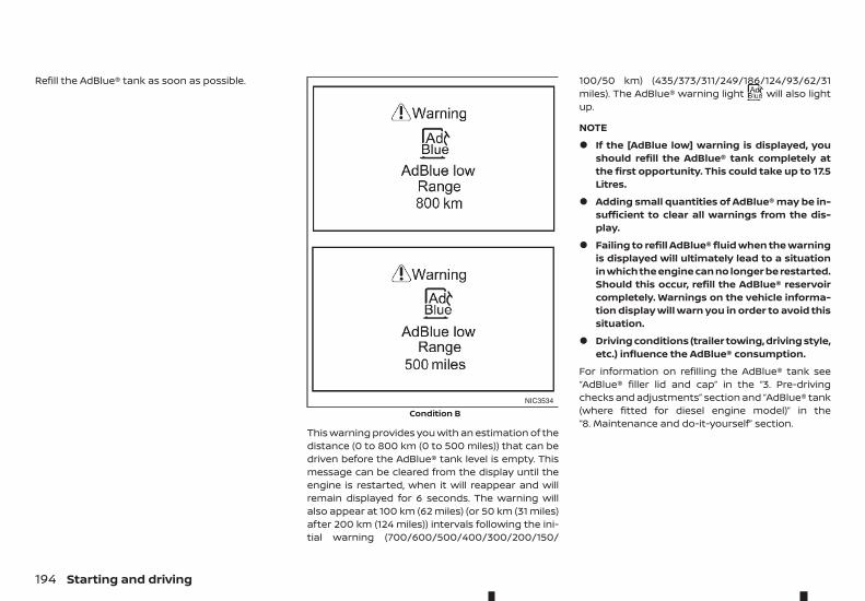
Refill the AdBlue® tank as soon as possible.
This warning provides you with an estimation of thedistance (0 to 800 km (0 to 500 miles)) that can bedriven before the AdBlue® tank level is empty. Thismessage can be cleared from the display until theengine is restarted, when it will reappear and willremain displayed for 6 seconds. The warning willalso appear at 100 km (62 miles) (or 50 km (31 miles)after 200 km (124 miles)) intervals following the ini-tial warning (700/600/500/400/300/200/150/
100/50 km) (435/373/311/249/186/124/93/62/31miles). The AdBlue® warning light will also lightup.
NOTE
• If the [AdBlue low] warning is displayed, youshould refill the AdBlue® tank completely atthe first opportunity. This could take up to 17.5Litres.
• Adding small quantities of AdBlue® may be in-sufficient to clear all warnings from the dis-play.
• Failing to refill AdBlue® fluid when the warningis displayed will ultimately lead to a situationin which the engine can no longer be restarted.Should this occur, refill the AdBlue® reservoircompletely. Warnings on the vehicle informa-tion display will warn you in order to avoid thissituation.
• Driving conditions (trailer towing, driving style,etc.) influence the AdBlue® consumption.
For information on refilling the AdBlue® tank see“AdBlue® filler lid and cap” in the “3. Pre-drivingchecks and adjustments” section and “AdBlue® tank(where fitted for diesel engine model)” in the“8. Maintenance and do-it-yourself” section.
NIC3534
Condition B
194 Starting and driving
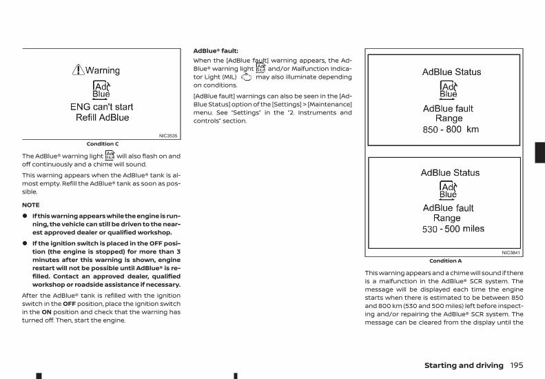
The AdBlue® warning light will also flash on andoff continuously and a chime will sound.
This warning appears when the AdBlue® tank is al-most empty. Refill the AdBlue® tank as soon as pos-sible.
NOTE
• If this warning appears while the engine is run-ning, the vehicle can still be driven to the near-est approved dealer or qualified workshop.
• If the ignition switch is placed in the OFF posi-tion (the engine is stopped) for more than 3minutes after this warning is shown, enginerestart will not be possible until AdBlue® is re-filled. Contact an approved dealer, qualifiedworkshop or roadside assistance if necessary.
After the AdBlue® tank is refilled with the ignitionswitch in the OFF position, place the ignition switchin the ON position and check that the warning hasturned off. Then, start the engine.
AdBlue® fault:When the [AdBlue fault] warning appears, the Ad-Blue® warning light and/or Malfunction Indica-tor Light (MIL) may also illuminate dependingon conditions.
[AdBlue fault] warnings can also be seen in the [Ad-Blue Status] option of the [Settings] > [Maintenance]menu. See “Settings” in the “2. Instruments andcontrols” section.
This warning appears and a chime will sound if thereis a malfunction in the AdBlue® SCR system. Themessage will be displayed each time the enginestarts when there is estimated to be between 850and 800 km (530 and 500 miles) left before inspect-ing and/or repairing the AdBlue® SCR system. Themessage can be cleared from the display until the
NIC3535
Condition C
NIC3841
Condition A
Starting and driving 195
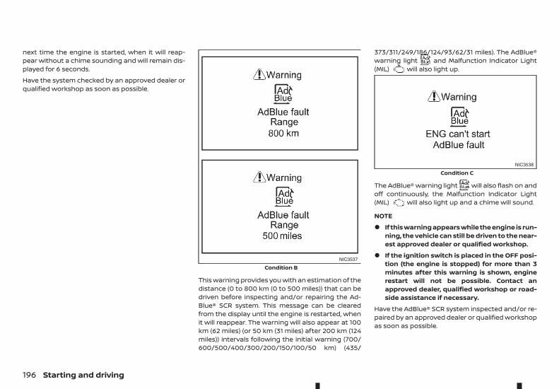
next time the engine is started, when it will reap-pear without a chime sounding and will remain dis-played for 6 seconds.
Have the system checked by an approved dealer orqualified workshop as soon as possible.
This warning provides you with an estimation of thedistance (0 to 800 km (0 to 500 miles)) that can bedriven before inspecting and/or repairing the Ad-Blue® SCR system. This message can be clearedfrom the display until the engine is restarted, whenit will reappear. The warning will also appear at 100km (62 miles) (or 50 km (31 miles) after 200 km (124miles)) intervals following the initial warning (700/600/500/400/300/200/150/100/50 km) (435/
373/311/249/186/124/93/62/31 miles). The AdBlue®warning light and Malfunction Indicator Light(MIL) will also light up.
The AdBlue® warning light will also flash on andoff continuously, the Malfunction Indicator Light(MIL) will also light up and a chime will sound.
NOTE
• If this warning appears while the engine is run-ning, the vehicle can still be driven to the near-est approved dealer or qualified workshop.
• If the ignition switch is placed in the OFF posi-tion (the engine is stopped) for more than 3minutes after this warning is shown, enginerestart will not be possible. Contact anapproved dealer, qualified workshop or road-side assistance if necessary.
Have the AdBlue® SCR system inspected and/or re-paired by an approved dealer or qualified workshopas soon as possible.
NIC3537
Condition B
NIC3538
Condition C
196 Starting and driving
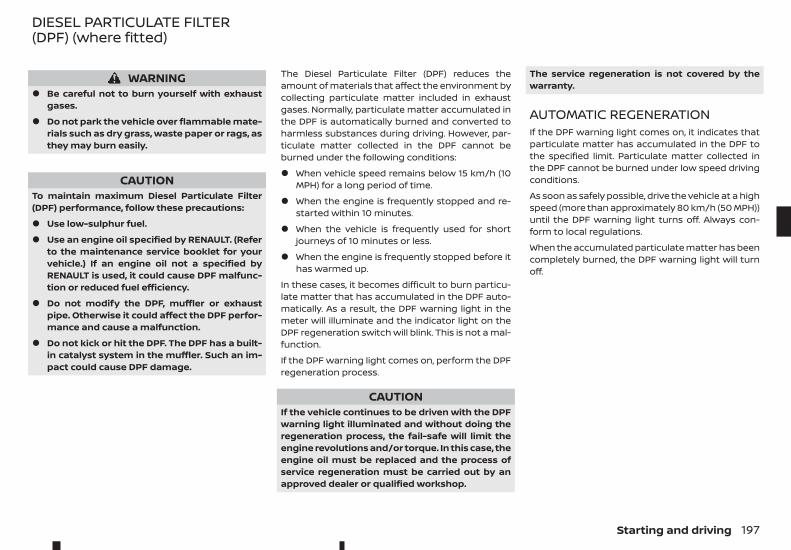
WARNING• Be careful not to burn yourself with exhaust
gases.
• Do not park the vehicle over flammable mate-rials such as dry grass, waste paper or rags, asthey may burn easily.
CAUTIONTo maintain maximum Diesel Particulate Filter(DPF) performance, follow these precautions:
• Use low-sulphur fuel.
• Use an engine oil specified by RENAULT. (Referto the maintenance service booklet for yourvehicle.) If an engine oil not a specified byRENAULT is used, it could cause DPF malfunc-tion or reduced fuel efficiency.
• Do not modify the DPF, muffler or exhaustpipe. Otherwise it could affect the DPF perfor-mance and cause a malfunction.
• Do not kick or hit the DPF. The DPF has a built-in catalyst system in the muffler. Such an im-pact could cause DPF damage.
The Diesel Particulate Filter (DPF) reduces theamount of materials that affect the environment bycollecting particulate matter included in exhaustgases. Normally, particulate matter accumulated inthe DPF is automatically burned and converted toharmless substances during driving. However, par-ticulate matter collected in the DPF cannot beburned under the following conditions:
• When vehicle speed remains below 15 km/h (10MPH) for a long period of time.
• When the engine is frequently stopped and re-started within 10 minutes.
• When the vehicle is frequently used for shortjourneys of 10 minutes or less.
• When the engine is frequently stopped before ithas warmed up.
In these cases, it becomes difficult to burn particu-late matter that has accumulated in the DPF auto-matically. As a result, the DPF warning light in themeter will illuminate and the indicator light on theDPF regeneration switch will blink. This is not a mal-function.
If the DPF warning light comes on, perform the DPFregeneration process.
CAUTIONIf the vehicle continues to be driven with the DPFwarning light illuminated and without doing theregeneration process, the fail-safe will limit theengine revolutions and/or torque. In this case, theengine oil must be replaced and the process ofservice regeneration must be carried out by anapproved dealer or qualified workshop.
The service regeneration is not covered by thewarranty.
AUTOMATIC REGENERATIONIf the DPF warning light comes on, it indicates thatparticulate matter has accumulated in the DPF tothe specified limit. Particulate matter collected inthe DPF cannot be burned under low speed drivingconditions.
As soon as safely possible, drive the vehicle at a highspeed (more than approximately 80 km/h (50 MPH))until the DPF warning light turns off. Always con-form to local regulations.
When the accumulated particulate matter has beencompletely burned, the DPF warning light will turnoff.
DIESEL PARTICULATE FILTER(DPF) (where fitted)
Starting and driving 197
Pick-up vehicles have a significantly higher roll-over rate than other types of vehicles.
They have higher ground clearance than passengercars to make them capable of performing in a widevariety of on-pavement and off-road applications.This gives them a higher centre of gravity than ordi-nary cars. An advantage of higher ground clearanceis a better view of the road, allowing you to antici-pate problems. However, they are not designed forcornering at the same speeds as conventional pas-senger cars any more than low-slung sports carsare designed to perform satisfactorily under off-road conditions. If at all possible, avoid sharp turnsor abrupt manoeuvres, particularly at high speeds.As with other vehicles of this type, failure to operatethis vehicle correctly may result in loss of control orvehicle rollover.
For information about driving using Four-WheelDrive (4WD) (where fitted), see “Four-Wheel Drive(4WD) (where fitted)” later in this section.
DRIVING SAFETY PRECAUTIONSPlease observe the following precautions:
WARNING• Drive carefully when off the road and avoid
dangerous areas. Every person who drives orrides in this vehicle should be seated with theirseat belt fastened. This will keep you and yourpassengers in position when driving overrough terrain.
• Do not drive across steep slopes. Instead driveeither straight up or straight down the slopes.Off-road vehicles can tip over sideways muchmore easily than they can forward or back-ward.
• Many hills are too steep for any vehicle. If youdrive up them, you may stall. If you drive downthem, you may not be able to control yourspeed. If you drive across them, you may rollover.
• Do not shift ranges while driving on downhillgrades as this could cause loss of control ofthe vehicle.
• Stay alert when driving to the top of a hill. Atthe top there could be a drop-off or other haz-ard that could cause an accident.
• If your engine stalls or you cannot make it tothe top of a steep hill, never attempt to turnaround. Your vehicle could tip or roll over. Al-ways back straight down in R (Reverse) range.Never back down in N (Neutral) or with theclutch pedal depressed (MT model) using onlythe brake, as this could cause loss of control.
• Heavy braking going down a hill could causeyour brakes to overheat and fade, resulting inloss of control and an accident. Apply brakeslightly and use a low range to control yourspeed.
• Unsecured cargo can be thrown around whendriving over rough terrain. Properly secure allcargo so it will not be thrown forward andcause injury to you or your passengers.
• To avoid raising the centre of gravity exces-sively, do not exceed the rated capacity of theroof rail (where fitted) and evenly distributethe load. Secure heavy loads in the cargo areaas far forward and as low as possible. Do notequip the vehicle with tyres larger than speci-fied in this manual. This could cause your ve-hicle to roll over.
• Do not grip the inside or spokes of the steer-ing wheel when driving off-road. The steeringwheel could move suddenly and injure yourhands. Instead drive with your fingers andthumbs on the outside of the rim.
• Before operating the vehicle, ensure that thedriver and all passengers have their seat beltsfastened.
• Always drive with the floor mats in place asthe floor may became hot.
• Lower your speed when encountering strongcrosswinds. With a higher centre of gravity,your vehicle is more affected by strong sidewinds. Slower speeds ensure better vehiclecontrol.
• Do not drive beyond the performance capabil-ity of the tyres, even with 4WD engaged.
• Do not attempt to raise two wheels off theground and shift the transmission to any driveor reverse position with the engine running.Doing so may result in drivetrain damage orunexpected vehicle movement which couldresult in serious vehicle damage or personalinjury.
ON-ROAD AND OFF-ROADDRIVING PRECAUTIONS
198 Starting and driving
• Do not attempt to test a 4WD equipped ve-hicle on a 2-wheel dynamometer or similarequipment even if the other two wheels areraised off the ground. Make sure you informtest facility personnel that your vehicle isequipped with 4WD before it is placed on a dy-namometer. Using the wrong test equipmentmay result in drivetrain damage or unex-pected vehicle movement which could resultin serious vehicle damage or personal injury.
• When a wheel is off the ground due to an un-level surface, do not spin the wheelexcessively.
• Accelerating quickly, sharp steering manoeu-vres or sudden braking may cause loss of con-trol.
• If at all possible, avoid sharp turning manoeu-vres, particularly at high speeds. Your vehiclehas a higher centre of gravity than a conven-tional passenger car. The vehicle is not de-signed for cornering at the same speeds asconventional passenger cars. Failure to oper-ate this vehicle correctly could result in loss ofcontrol and/or a rollover accident.
• Always use tyres of the same type, size, brand,construction (bias, bias-belted or radial), andtread pattern on all four wheels. Install tyrechains on the rear wheels when driving onslippery roads and drive carefully.
• Be sure to check the brakes immediately afterdriving in mud or water. See “Brake system”later in this section for wet brakes.
• Avoid parking your vehicle on steep hills. If youget out of the vehicle and it rolls forward, back-ward or sideways, you could be injured.
• Whenever you drive off-road through sand,mud or water as deep as the wheel hub, morefrequent maintenance may be required. Seethe maintenance information in a separatemaintenance booklet.
• Rinse the underside of the vehicle with freshwater after driving through mud or sand. Re-move any brush or sticks that are trapped.
The turbocharger system uses engine oil for lubri-cation and cooling of its rotating components. Theturbocharger turbine turns at extremely highspeeds and it can reach an extremely high tempera-ture. It is essential to maintain a flow of clean oilthrough the turbocharger system. A sudden inter-ruption to the oil supply may cause a malfunction inthe turbocharger.
To ensure prolonged life and performance of theturbocharger, it is essential to comply with the fol-lowing maintenance procedure:
CAUTION• Change the engine oil of the turbo-charged
diesel engine as prescribed. See the sepa-rately provided maintenance booklet for ad-ditional information.
• Use only the recommended engine oil. For de-tails, refer to the maintenance service bookletfor your vehicle.
• If the engine has been operating at high rpmfor an extended period of time, let it idle for afew minutes prior to shutdown.
• Do not accelerate the engine to high rpm im-mediately after starting it.
• When starting the engine at ambienttemperatures below −5°C (23°F), an engineprotection mode may be activated. During thistime, the engine output is reduced. The engineprotection mode is switched off automaticallyafter a maximum of 3 minutes (provided theaccelerator pedal is released completely).
TURBOCHARGER SYSTEM
Starting and driving 199
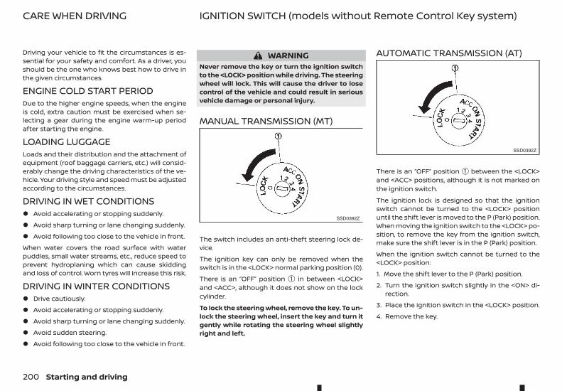
Driving your vehicle to fit the circumstances is es-sential for your safety and comfort. As a driver, youshould be the one who knows best how to drive inthe given circumstances.
ENGINE COLD START PERIODDue to the higher engine speeds, when the engineis cold, extra caution must be exercised when se-lecting a gear during the engine warm-up periodafter starting the engine.
LOADING LUGGAGELoads and their distribution and the attachment ofequipment (roof baggage carriers, etc.) will consid-erably change the driving characteristics of the ve-hicle. Your driving style and speed must be adjustedaccording to the circumstances.
DRIVING IN WET CONDITIONS• Avoid accelerating or stopping suddenly.
• Avoid sharp turning or lane changing suddenly.
• Avoid following too close to the vehicle in front.
When water covers the road surface with waterpuddles, small water streams, etc., reduce speed toprevent hydroplaning which can cause skiddingand loss of control. Worn tyres will increase this risk.
DRIVING IN WINTER CONDITIONS• Drive cautiously.
• Avoid accelerating or stopping suddenly.
• Avoid sharp turning or lane changing suddenly.
• Avoid sudden steering.
• Avoid following too close to the vehicle in front.
WARNINGNever remove the key or turn the ignition switchto the <LOCK> position while driving. The steeringwheel will lock. This will cause the driver to losecontrol of the vehicle and could result in seriousvehicle damage or personal injury.
MANUAL TRANSMISSION (MT)
The switch includes an anti-theft steering lock de-vice.
The ignition key can only be removed when theswitch is in the <LOCK> normal parking position (0).
There is an “OFF” position ➀ in between <LOCK>and <ACC>, although it does not show on the lockcylinder.
To lock the steering wheel, remove the key. To un-lock the steering wheel, insert the key and turn itgently while rotating the steering wheel slightlyright and left.
AUTOMATIC TRANSMISSION (AT)
There is an “OFF” position ➀ between the <LOCK>and <ACC> positions, although it is not marked onthe ignition switch.
The ignition lock is designed so that the ignitionswitch cannot be turned to the <LOCK> positionuntil the shift lever is moved to the P (Park) position.When moving the ignition switch to the <LOCK> po-sition, to remove the key from the ignition switch,make sure the shift lever is in the P (Park) position.
When the ignition switch cannot be turned to the<LOCK> position:
1. Move the shift lever to the P (Park) position.
2. Turn the ignition switch slightly in the <ON> di-rection.
3. Place the ignition switch in the <LOCK> position.
4. Remove the key.
SSD0392Z
SSD0392Z
CARE WHEN DRIVING IGNITION SWITCH (models without Remote Control Key system)
200 Starting and driving
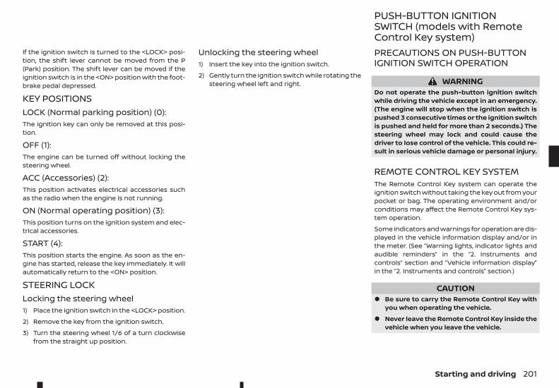
If the ignition switch is turned to the <LOCK> posi-tion, the shift lever cannot be moved from the P(Park) position. The shift lever can be moved if theignition switch is in the <ON> position with the foot-brake pedal depressed.
KEY POSITIONSLOCK (Normal parking position) (0):The ignition key can only be removed at this posi-tion.
OFF (1):The engine can be turned off without locking thesteering wheel.
ACC (Accessories) (2):This position activates electrical accessories suchas the radio when the engine is not running.
ON (Normal operating position) (3):This position turns on the ignition system and elec-trical accessories.
START (4):This position starts the engine. As soon as the en-gine has started, release the key immediately. It willautomatically return to the <ON> position.
STEERING LOCKLocking the steering wheel1) Place the ignition switch in the <LOCK> position.
2) Remove the key from the ignition switch.
3) Turn the steering wheel 1/6 of a turn clockwisefrom the straight up position.
Unlocking the steering wheel1) Insert the key into the ignition switch.
2) Gently turn the ignition switch while rotating thesteering wheel left and right.
PRECAUTIONS ON PUSH-BUTTONIGNITION SWITCH OPERATION
WARNINGDo not operate the push-button ignition switchwhile driving the vehicle except in an emergency.(The engine will stop when the ignition switch ispushed 3 consecutive times or the ignition switchis pushed and held for more than 2 seconds.) Thesteering wheel may lock and could cause thedriver to lose control of the vehicle. This could re-sult in serious vehicle damage or personal injury.
REMOTE CONTROL KEY SYSTEMThe Remote Control Key system can operate theignition switch without taking the key out from yourpocket or bag. The operating environment and/orconditions may affect the Remote Control Key sys-tem operation.
Some indicators and warnings for operation are dis-played in the vehicle information display and/or inthe meter. (See “Warning lights, indicator lights andaudible reminders” in the “2. Instruments andcontrols” section and “Vehicle information display”in the “2. Instruments and controls” section.)
CAUTION• Be sure to carry the Remote Control Key with
you when operating the vehicle.
• Never leave the Remote Control Key inside thevehicle when you leave the vehicle.
PUSH-BUTTON IGNITIONSWITCH (models with RemoteControl Key system)
Starting and driving 201
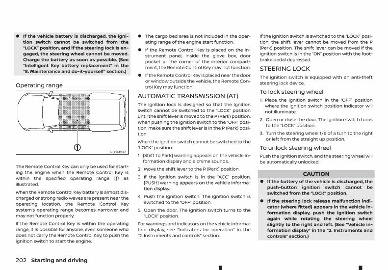
• If the vehicle battery is discharged, the igni-tion switch cannot be switched from the“LOCK” position, and if the steering lock is en-gaged, the steering wheel cannot be moved.Charge the battery as soon as possible. (See“Intelligent Key battery replacement” in the“8. Maintenance and do-it-yourself” section.)
Operating range
The Remote Control Key can only be used for start-ing the engine when the Remote Control Key iswithin the specified operating range ➀ asillustrated.
When the Remote Control Key battery is almost dis-charged or strong radio waves are present near theoperating location, the Remote Control Keysystem’s operating range becomes narrower andmay not function properly.
If the Remote Control Key is within the operatingrange, it is possible for anyone, even someone whodoes not carry the Remote Control Key, to push theignition switch to start the engine.
• The cargo bed area is not included in the oper-ating range of the engine start function.
• If the Remote Control Key is placed on the in-strument panel, inside the glove box, doorpocket or the corner of the interior compart-ment, the Remote Control Key may not function.
• If the Remote Control Key is placed near the dooror window outside the vehicle, the Remote Con-trol Key may function.
AUTOMATIC TRANSMISSION (AT)The ignition lock is designed so that the ignitionswitch cannot be switched to the “LOCK” positionuntil the shift lever is moved to the P (Park) position.When pushing the ignition switch to the “OFF” posi-tion, make sure the shift lever is in the P (Park) posi-tion.
When the ignition switch cannot be switched to the“LOCK” position:
1. [Shift to Park] warning appears on the vehicle in-formation display and a chime sounds.
2. Move the shift lever to the P (Park) position.
3. If the ignition switch is in the “ACC” position,[PUSH] warning appears on the vehicle informa-tion display.
4. Push the ignition switch. The ignition switch isswitched to the “OFF” position.
5. Open the door. The ignition switch turns to the“LOCK” position.
For warnings and indicators on the vehicle informa-tion display, see “Indicators for operation” in the“2. Instruments and controls” section.
If the ignition switch is switched to the “LOCK” posi-tion, the shift lever cannot be moved from the P(Park) position. The shift lever can be moved if theignition switch is in the “ON” position with the foot-brake pedal depressed.
STEERING LOCKThe ignition switch is equipped with an anti-theftsteering lock device.
To lock steering wheel1. Place the ignition switch in the “OFF” position
where the ignition switch position indicator willnot illuminate.
2. Open or close the door. The ignition switch turnsto the “LOCK” position.
3. Turn the steering wheel 1/6 of a turn to the rightor left from the straight up position.
To unlock steering wheelPush the ignition switch, and the steering wheel willbe automatically unlocked.
CAUTION• If the battery of the vehicle is discharged, the
push-button ignition switch cannot beswitched from the “LOCK” position.
• If the steering lock release malfunction indi-cator (where fitted) appears in the vehicle in-formation display, push the ignition switchagain while rotating the steering wheelslightly to the right and left. (See “Vehicle in-formation display” in the “2. Instruments andcontrols” section.)
JVS0442XZ
202 Starting and driving
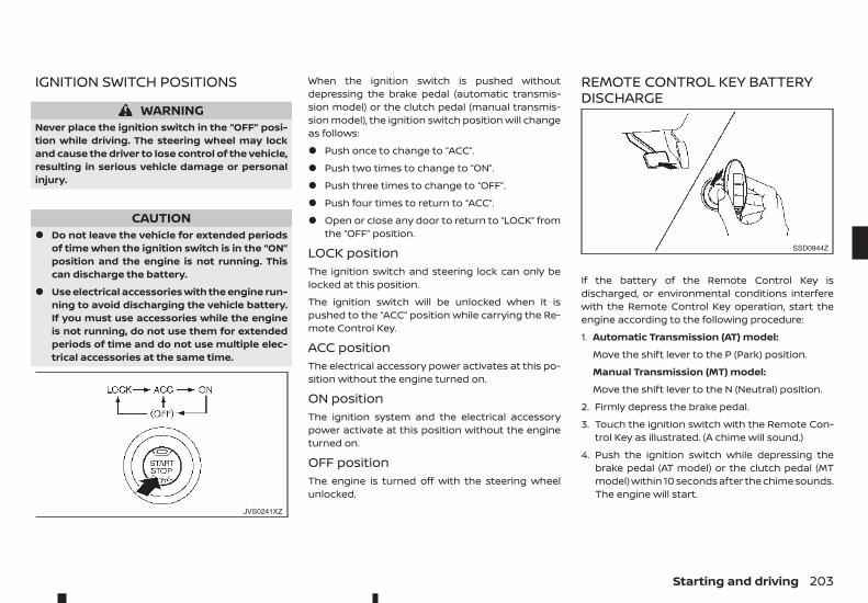
IGNITION SWITCH POSITIONS
WARNINGNever place the ignition switch in the “OFF” posi-tion while driving. The steering wheel may lockand cause the driver to lose control of the vehicle,resulting in serious vehicle damage or personalinjury.
CAUTION• Do not leave the vehicle for extended periods
of time when the ignition switch is in the “ON”position and the engine is not running. Thiscan discharge the battery.
• Use electrical accessories with the engine run-ning to avoid discharging the vehicle battery.If you must use accessories while the engineis not running, do not use them for extendedperiods of time and do not use multiple elec-trical accessories at the same time.
When the ignition switch is pushed withoutdepressing the brake pedal (automatic transmis-sion model) or the clutch pedal (manual transmis-sion model), the ignition switch position will changeas follows:
• Push once to change to “ACC”.
• Push two times to change to “ON”.
• Push three times to change to “OFF”.
• Push four times to return to “ACC”.
• Open or close any door to return to “LOCK” fromthe “OFF” position.
LOCK positionThe ignition switch and steering lock can only belocked at this position.
The ignition switch will be unlocked when it ispushed to the “ACC” position while carrying the Re-mote Control Key.
ACC positionThe electrical accessory power activates at this po-sition without the engine turned on.
ON positionThe ignition system and the electrical accessorypower activate at this position without the engineturned on.
OFF positionThe engine is turned off with the steering wheelunlocked.
REMOTE CONTROL KEY BATTERYDISCHARGE
If the battery of the Remote Control Key isdischarged, or environmental conditions interferewith the Remote Control Key operation, start theengine according to the following procedure:
1. Automatic Transmission (AT) model:
Move the shift lever to the P (Park) position.
Manual Transmission (MT) model:
Move the shift lever to the N (Neutral) position.
2. Firmly depress the brake pedal.
3. Touch the ignition switch with the Remote Con-trol Key as illustrated. (A chime will sound.)
4. Push the ignition switch while depressing thebrake pedal (AT model) or the clutch pedal (MTmodel) within 10 seconds after the chime sounds.The engine will start.
JVS0241XZ
SSD0944Z
Starting and driving 203
After step 3 is performed, when the ignition switchis pushed without depressing the brake pedal (ATmodel) or the clutch pedal (MT model), the ignitionswitch position will change to “ACC”.
NOTE
• When the ignition switch is pushed to the“ACC” or “ON” position or the engine is startedby the above procedures, the Key Battery lowwarning appears on the vehicle informationdisplay even if the Remote Control Key is in-side the vehicle. This is not a malfunction. Toturn off the warning, touch the ignition switchwith the Remote Control Key again.
• If the Key Battery low warning appears on thevehicle information display, replace the bat-tery as soon as possible. (See “Intelligent Keybattery replacement” in the “8. Maintenanceand do-it-yourself” section.)
1. Apply the parking brake.
2. Depress the footbrake pedal.
3. Automatic Transmission (AT) model:
Move the shift lever to the P (Park) or the N (Neu-tral) position.
The starter is designed to operate only whenthe shift lever is in the proper position.
Manual Transmission (MT) model:
Move the shift lever to the N (Neutral) positionand depress the clutch pedal to the floor whilestarting the engine.
4. Crank the engine with your foot off the accelera-tor pedal by placing the ignition switch in the<START> position.
Place the ignition switch in the <ON> position andwait until the glow plug indicator lightturns off.
5. Immediately release the ignition switch when theengine starts. If the engine starts, but fails to run,repeat the above procedures.
6. Allow the engine to idle for at least 30 secondsafter starting the engine to warm-up. Drive atmoderate speeds for a short distance first, espe-cially in cold weather.
CAUTIONDo not leave the vehicle unattended while the en-gine is warming up.
1. Apply the parking brake.
2. Automatic Transmission (AT) model:
Move the shift lever to the P (Park) or the N (Neu-tral) position.
The starter is designed to operate only whenthe shift lever is in the proper position.
Manual Transmission (MT) model:
Move the shift lever to the N (Neutral) position.
The Remote Control Key must be carried whenoperating the ignition switch.
3. Place the ignition switch in the “ON” position. De-press the brake pedal (AT model) or the clutchpedal (MT model) and push the ignition switch tostart the engine.
For diesel engine models: Wait until the glowplug indicator light goes out.
To start the engine immediately, push and re-lease the ignition switch while depressing thebrake pedal or clutch pedal with the ignitionswitch in any position.
4. Immediately release the ignition switch when theengine starts. If the engine starts, but fails to run,repeat the above procedures.
5. Allow the engine to idle for at least 30 secondsafter starting the engine to warm-up. Drive atmoderate speeds for a short distance first, espe-cially in cold weather.
CAUTIONDo not leave the vehicle unattended while theengine is warming up.
STARTING ENGINE (modelswithout Remote Control Keysystem)
STARTING ENGINE (models withRemote Control Key system)
204 Starting and driving
6. To stop the engine, move the shift lever to the P(Park) (AT model) or N (Neutral) (MT model) posi-tion, apply the parking brake, and place the igni-tion switch in the “OFF” position.
DRIVING WITH AUTOMATICTRANSMISSION (AT)The Automatic Transmission (AT) in your vehicle iselectronically controlled to produce maximumpower and smooth operation.
The recommended operating procedures for thistransmission are shown on the following pages. Fol-low these procedures for maximum vehicle perfor-mance and driving enjoyment.
WARNINGDo not downshift abruptly on slippery roads. Thismay cause a loss of control.
CAUTION• The cold engine idle speed is high, so use cau-
tion when shifting into a forward or reversegear before the engine has warmed up.
• Avoid revving up the engine while the vehicleis stopped. This could cause unexpected ve-hicle movement.
• Never shift to either the P (Park) or R (Reverse)position while the vehicle is moving forwardand P (Park) or D (Drive) position while the ve-hicle is reversing. This could cause an accidentor damage the transmission.
• Except in an emergency, do not shift to the N(Neutral) position while driving. Coasting withthe transmission in the N (Neutral) positionmay cause serious damage to the transmis-sion.
• Start the engine in either the P (Park) or N(Neutral) position. The engine will not start inany other gear position. If it does, have yourvehicle checked by an approved dealer orqualified workshop.
• Shift into the P (Park) position and apply theparking brake when at a standstill for longerthan a short waiting period.
• Keep the engine at idling speed while shiftingfrom the N (Neutral) position to any driving po-sition.
• To avoid possible damage to your vehicle;when stopping the vehicle on an uphill grade,do not hold the vehicle by depressing the ac-celerator pedal. The footbrake should be usedfor this purpose.
Starting vehicle1. After starting the engine, fully depress the foot-
brake pedal before attempting to move the shiftlever out of the P (Park) position.
2. Keep the footbrake pedal depressed and movethe shift lever into a driving position.
3. Release the parking brake, the footbrake pedal,and then gradually start the vehicle in motion.
The AT is designed so the footbrake pedal MUSTbe depressed before shifting from the P (Park)position to any driving position while the ignitionswitch is in the “ON” position.
The shift lever cannot be moved out of the P (Park)position and into any of the other gear positionsif the ignition switch is placed in the “LOCK”, “OFF”or “ACC” position.
DRIVING THE VEHICLE
Starting and driving 205
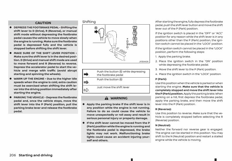
CAUTION• DEPRESS THE FOOTBRAKE PEDAL - Shifting the
shift lever to D (Drive), R (Reverse), or manualshift mode without depressing the footbrakepedal causes the vehicle to move slowly whenthe engine is running. Make sure the footbrakepedal is depressed fully and the vehicle isstopped before shifting the shift lever.
• MAKE SURE OF THE SHIFT LEVER POSITION -Make sure the shift lever is in the desired posi-tion. D (Drive) and manual shift mode are usedto move forward and R (Reverse) to reverse.Depress the accelerator pedal to start the ve-hicle and merge with traffic (avoid abruptstarting and spinning the wheels).
• WARM UP THE ENGINE - Due to the higher idlespeeds when the engine is cold, extra cautionmust be exercised when shifting the shift le-ver into the driving position immediately afterstarting the engine.
• PARKING THE VEHICLE - Depress the footbrakepedal and, once the vehicle stops, move theshift lever into the P (Park) position, pull theparking brake lever and release the footbrakepedal.
Shifting
m:Push the buttonjA while depressingthe footbrake pedal
m:Push the buttonjA
m:Just move the shift lever
WARNING
• Apply the parking brake if the shift lever is inany position while the engine is not running.Failure to do so could cause the vehicle tomove unexpectedly or roll away and result inserious personal injury or property damage.
• If the shift lever cannot be moved from the P(Park) position while the engine is running andthe footbrake pedal is depressed, the brakelights may not work. Malfunctioning brakelights could cause an accident injuring your-self and others.
After starting the engine, fully depress the footbrakepedal, push the shift lever button and move the shiftlever out of the P (Park) position.
If the ignition switch is placed in the “OFF” or “ACC”position for any reason while the shift lever is in anypositions other than the P (Park) position, the igni-tion switch cannot be placed in the “LOCK” position.
If the ignition switch cannot be placed in the “LOCK”position, perform the following steps:
1. Apply the parking brake.
2. Place the ignition switch in the “ON” positionwhile depressing the footbrake pedal.
3. Move the shift lever to the P (Park) position.
4. Place the ignition switch in the “LOCK” position.
P (Park):Use this position when the vehicle is parked or whenstarting the engine. Make sure that the vehicle iscompletely stopped and move the shift lever intothe P (Park) position. Apply the parking brake.Whenparking on a hill, first depress the footbrake pedal,apply the parking brake, and then move the shiftlever into the P (Park) position.
R (Reverse):Use this position to reverse. Make sure that the ve-hicle is completely stopped before selecting the R(Reverse) position.
N (Neutral):Neither the forward nor reverse gear is engaged.The engine can be started in this position. You mayshift to the N (Neutral) position and restart a stalledengine while the vehicle is moving.
JVS0443X
206 Starting and driving
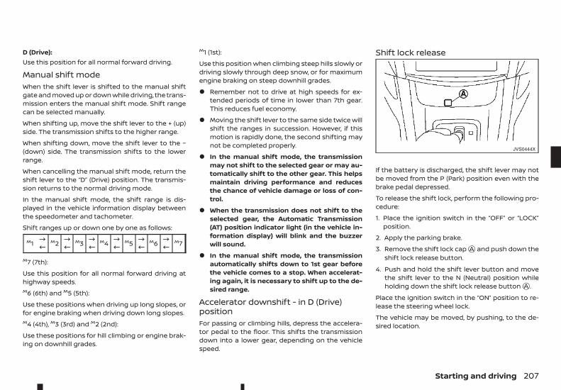
D (Drive):Use this position for all normal forward driving.
Manual shift modeWhen the shift lever is shifted to the manual shiftgate and moved up or down while driving, the trans-mission enters the manual shift mode. Shift rangecan be selected manually.
When shifting up, move the shift lever to the + (up)side. The transmission shifts to the higher range.
When shifting down, move the shift lever to the −(down) side. The transmission shifts to the lowerrange.
When cancelling the manual shift mode, return theshift lever to the “D” (Drive) position. The transmis-sion returns to the normal driving mode.
In the manual shift mode, the shift range is dis-played in the vehicle information display betweenthe speedometer and tachometer.
Shift ranges up or down one by one as follows:
M1 !" M2 !" M3 !" M4 !" M5 !" M6 !" M7
M7 (7th):
Use this position for all normal forward driving athighway speeds.M6 (6th) and M5 (5th):
Use these positions when driving up long slopes, orfor engine braking when driving down long slopes.M4 (4th), M3 (3rd) and M2 (2nd):
Use these positions for hill climbing or engine brak-ing on downhill grades.
M1 (1st):
Use this position when climbing steep hills slowly ordriving slowly through deep snow, or for maximumengine braking on steep downhill grades.
• Remember not to drive at high speeds for ex-tended periods of time in lower than 7th gear.This reduces fuel economy.
• Moving the shift lever to the same side twice willshift the ranges in succession. However, if thismotion is rapidly done, the second shifting maynot be completed properly.
• In the manual shift mode, the transmissionmay not shift to the selected gear or may au-tomatically shift to the other gear. This helpsmaintain driving performance and reducesthe chance of vehicle damage or loss of con-trol.
• When the transmission does not shift to theselected gear, the Automatic Transmission(AT) position indicator light (in the vehicle in-formation display) will blink and the buzzerwill sound.
• In the manual shift mode, the transmissionautomatically shifts down to 1st gear beforethe vehicle comes to a stop. When accelerat-ing again, it is necessary to shift up to the de-sired range.
Accelerator downshift - in D (Drive)positionFor passing or climbing hills, depress the accelera-tor pedal to the floor. This shifts the transmissiondown into a lower gear, depending on the vehiclespeed.
Shift lock release
If the battery is discharged, the shift lever may notbe moved from the P (Park) position even with thebrake pedal depressed.
To release the shift lock, perform the following pro-cedure:
1. Place the ignition switch in the “OFF” or “LOCK”position.
2. Apply the parking brake.
3. Remove the shift lock capjA and push down theshift lock release button.
4. Push and hold the shift lever button and movethe shift lever to the N (Neutral) position whileholding down the shift lock release buttonjA .
Place the ignition switch in the “ON” position to re-lease the steering wheel lock.
The vehicle may be moved, by pushing, to the de-sired location.
JVS0444X
Starting and driving 207
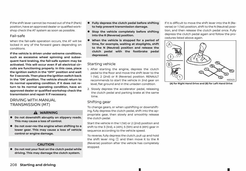
If the shift lever cannot be moved out of the P (Park)position, have an approved dealer or qualified work-shop check the AT system as soon as possible.
Fail-safeWhen the fail-safe operation occurs, the AT will belocked in any of the forward gears depending onconditions.
If the vehicle is driven under extreme conditions,such as excessive wheel spinning and subse-quent hard braking, the fail-safe system may beactivated. This will occur even if all electrical cir-cuits are functioning properly. In this case, placethe ignition switch in the “OFF” position and waitfor 3 seconds. Then place the ignition switch backin the “ON” position. The vehicle should return toits normal operating condition. If it does not re-turn to its normal operating condition, have anapproved dealer or qualified workshop check thetransmission and repair it if necessary.
DRIVING WITH MANUALTRANSMISSION (MT)
WARNING• Do not downshift abruptly on slippery roads.
This may cause a loss of control.
• Do not over-rev the engine when shifting to alower gear. This may cause a loss of vehiclecontrol or engine damage.
CAUTION• Do not rest your foot on the clutch pedal while
driving. This may damage the clutch system.
• Fully depress the clutch pedal before shiftingto help prevent transmission damage.
• Stop the vehicle completely before shiftinginto the R (Reverse) position.
• When the vehicle is stopped for a period oftime, for example, waiting at stoplights, shiftto the N (Neutral) position and release theclutch pedal with the footbrake pedaldepressed.
Starting vehicle1. After starting the engine, depress the clutch
pedal to the floor and move the shift lever to the1 (1st), 2 (2nd) or R (Reverse) position. RENAULTrecommends to start the vehicle in 2nd gear onlevel, flat ground and in the unladen condition.
2. Slowly depress the accelerator pedal, releasingthe clutch pedal and parking brake at the sametime.
Shifting gearTo change gears, or when upshifting or downshift-ing, fully depress the clutch pedal, shift into the ap-propriate gear, then slowly and smoothly releasethe clutch pedal.
Start the vehicle in the 1 (1st) or 2 (2nd) position andshift to the 3 (3rd), 4 (4th), 5 (5th) and 6 (6th) gear insequence according to the vehicle speed.
To reverse, fully depress the clutch, pull up and holdthe shift lever ring ➀ and then move it to the R(Reverse) position after the vehicle has completelystopped.
If it is difficult to move the shift lever into the R (Re-verse) or 1 (1st) position, shift to the N (Neutral) posi-tion, and then release the clutch pedal once. Fullydepress the clutch pedal again and follow the pro-cedures listed above again.
NSD525
(A) for Right Hand Drive and (B) for Left Hand Drive
208 Starting and driving
The Stop/Start System is designed to prevent un-necessary fuel consumption, exhaust emissions,and noise during a journey:
• When you stop the vehicle with the shift lever inN (Neutral) and clutch pedal released, the engineis turned off automatically.
• When you push the clutch pedal, the engine isautomatically turned on.
CAUTIONAt the end of the journey the engine must bestopped and ignition turned off. Lock the vehicleas normal. Turning the ignition switch OFF willshut down all electrical systems. Failure to do thismay result in a flat battery.
NOTE
For model with Stop/Start System, use the spe-cial battery that is enhanced in regard to thecharge-discharge capacity and life performance.Avoid using a non-special battery for the Stop/Start System, as this may cause early deteriora-tion of the battery or a malfunction of the Stop/Start System. For the battery, it is recommendedto use Genuine RENAULT parts. For more informa-tion, contact an approved dealer or qualifiedworkshop.
NOTE
The Stop/Start System will not activate under thefollowing conditions:
• When the engine is kept idling without anydriving after the engine is turned on.
• When the engine coolant temperature is low.
• When the battery capacity is low.
• When the battery temperature is low.
• When the vehicle is moved.
• When the vacuum in the brake servodecreases.
• When the engine bonnet is opened with theengine running.
• When the engine is turned on with the enginebonnet open.
• When the driver’s seat belt is not fastened.
• When the driver’s door is open.
• When the Stop/Start System indicator blinksat a low speed.
• When the fan speed control is in any positionother than OFF (0) while the air flow control isin the front defogger position.
• When the front defogger switch is on.
• When the temperature inside the vehicle is toohigh or low. (When the Auto air conditioningsystem is off, the Stop/Start System will oper-ate.)
• When the fan speed of the air conditioner isset to the maximum speed.
• When the Stop/Start OFF switch is turned on.
• When the power consumption is large.
• When the vehicle is travelling at altitudeshigher than 2000 m (6562 ft) (MT model).
• For Manual Transmission (MT) models
• When the shift lever is in any position exceptthe N (Neutral) position.
• When the clutch pedal is depressed.
• When the Remote Control Key is not in the ve-hicle.
• When the steering wheel is turning or turnedmore than 45 degrees.
NOTE
The engine will not restart even if the clutch pedalis pressed while the Stop/Start System is acti-vated under the following condition:
• When the engine bonnet is opened.
• When the driver seat belt is unfastened andthe driver’s door is opened.
• When the shift lever is not in the N (Neutral)position.
NOTE
It may take some time until the Stop/Start Sys-tem activates under the following conditions:
• When the battery is discharged.
• When the outside temperature is low or high.
• When the battery is replaced or the batteryterminal is disconnected for extended periodsand then reconnected.
STOP/START SYSTEM(where fitted)
Starting and driving 209
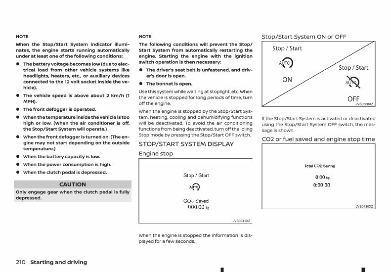
NOTE
When the Stop/Start System indicator illumi-nates, the engine starts running automaticallyunder at least one of the following conditions:
• The battery voltage becomes low (due to elec-trical load from other vehicle systems likeheadlights, heaters, etc., or auxiliary devicesconnected to the 12 volt socket inside the ve-hicle).
• The vehicle speed is above about 2 km/h (1MPH).
• The front defogger is operated.
• When the temperature inside the vehicle is toohigh or low. (When the air conditioner is off,the Stop/Start System will operate.)
• When the front defogger is turned on. (The en-gine may not start depending on the outsidetemperature.)
• When the battery capacity is low.
• When the power consumption is high.
• When the clutch pedal is depressed.
CAUTIONOnly engage gear when the clutch pedal is fullydepressed.
NOTE
The following conditions will prevent the Stop/Start System from automatically restarting theengine. Starting the engine with the ignitionswitch operation is then necessary:
• The driver’s seat belt is unfastened, and driv-er’s door is open.
• The bonnet is open.
Use this system while waiting at stoplight, etc. Whenthe vehicle is stopped for long periods of time, turnoff the engine.
When the engine is stopped by the Stop/Start Sys-tem, heating, cooling and dehumidifying functionswill be deactivated. To avoid the air conditioningfunctions from being deactivated, turn off the IdlingStop mode by pressing the Stop/Start OFF switch.
STOP/START SYSTEM DISPLAYEngine stop
When the engine is stopped the information is dis-played for a few seconds.
Stop/Start System ON or OFF
If the Stop/Start System is activated or deactivatedusing the Stop/Start System OFF switch, the mes-sage is shown.
CO2 or fuel saved and engine stop time
JVS0341XZ
JVS0638XZ
JVS0430XZ
210 Starting and driving
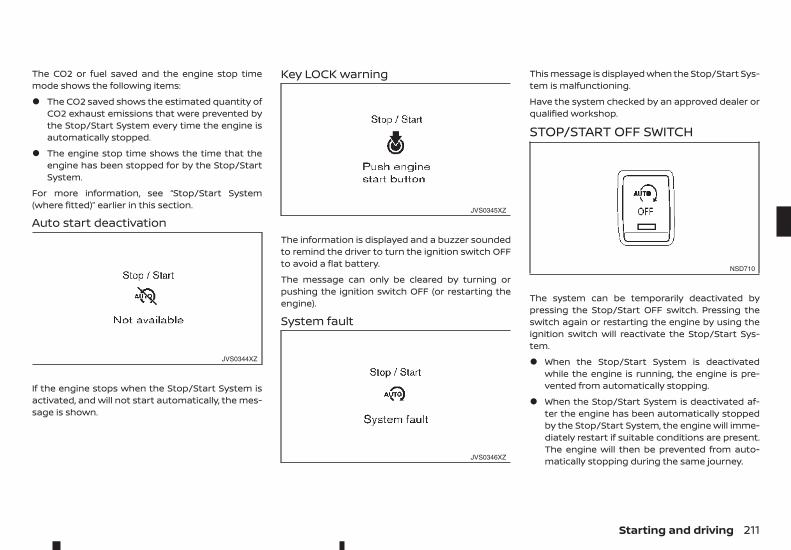
The CO2 or fuel saved and the engine stop timemode shows the following items:
• The CO2 saved shows the estimated quantity ofCO2 exhaust emissions that were prevented bythe Stop/Start System every time the engine isautomatically stopped.
• The engine stop time shows the time that theengine has been stopped for by the Stop/StartSystem.
For more information, see “Stop/Start System(where fitted)” earlier in this section.
Auto start deactivation
If the engine stops when the Stop/Start System isactivated, and will not start automatically, the mes-sage is shown.
Key LOCK warning
The information is displayed and a buzzer soundedto remind the driver to turn the ignition switch OFFto avoid a flat battery.
The message can only be cleared by turning orpushing the ignition switch OFF (or restarting theengine).
System fault
This message is displayed when the Stop/Start Sys-tem is malfunctioning.
Have the system checked by an approved dealer orqualified workshop.
STOP/START OFF SWITCH
The system can be temporarily deactivated bypressing the Stop/Start OFF switch. Pressing theswitch again or restarting the engine by using theignition switch will reactivate the Stop/Start Sys-tem.
• When the Stop/Start System is deactivatedwhile the engine is running, the engine is pre-vented from automatically stopping.
• When the Stop/Start System is deactivated af-ter the engine has been automatically stoppedby the Stop/Start System, the engine will imme-diately restart if suitable conditions are present.The engine will then be prevented from auto-matically stopping during the same journey.
JVS0344XZ
JVS0345XZ
JVS0346XZ
NSD710
Starting and driving 211
• Whenever the Stop/Start System is deactivatedthe indicator light ➀ on the Stop/Start OFFswitch illuminates. In this condition the Stop/Start System cannot prevent unnecessary fuelconsumption, exhaust emissions, or noise dur-ing your journey.
• If the Stop/Start System is malfunctioning, theindicator light ➀ on the Stop/Start OFF switchilluminates.
NOTE
The Stop/Start System ON or OFF messages dis-played for a few seconds in the vehicle informa-tion display when the Stop/Start OFF switch ispressed. See “Stop/Start System display” earlierin this section.
WARNING• Do not attempt to raise two wheels off the
ground and shift the transmission to any driveor reverse position with the engine running.Doing so may result in drivetrain damage orunexpected vehicle movement which couldresult in serious vehicle damage or personalinjury.
• Do not attempt to test a 4WD equipped ve-hicle on a 2-wheel dynamometer or similarequipment even if the other two wheels areraised off the ground. Make sure you informtest facility personnel that your vehicle isequipped with 4WD before it is placed on a dy-namometer. Using the wrong test equipmentmay result in drivetrain damage or unex-pected vehicle movement which could resultin serious vehicle damage or personal injury.
CAUTION• Do not drive the vehicle in the <4H> or <4LO>
position on dry hard surface roads. Driving ondry, hard surfaces in <4H> or <4LO> may causeunnecessary noise, tyre wear and increasedfuel consumption.
If the Four-Wheel Drive (4WD) warning lightturns on when driving on dry hard surfaceroads:
– in the <4H> position, shift the 4WD modeswitch to <2WD>.
– in the <4LO> position, stop the vehicle andshift the transmission lever to the N (Neu-tral) position with the brake pedaldepressed and shift the 4WD mode switchto <2WD>.
If the 4WD warning light is still on after theabove operation, have your vehiclechecked by an approved dealer or qualifiedworkshop as soon as possible.
• The transfer case may be damaged if you con-tinue driving with the 4WD warning lightblinking.
See “On-road and off-road driving precautions” ear-lier in this section for other precautions.
FOUR-WHEEL DRIVE (4WD)(where fitted)
212 Starting and driving
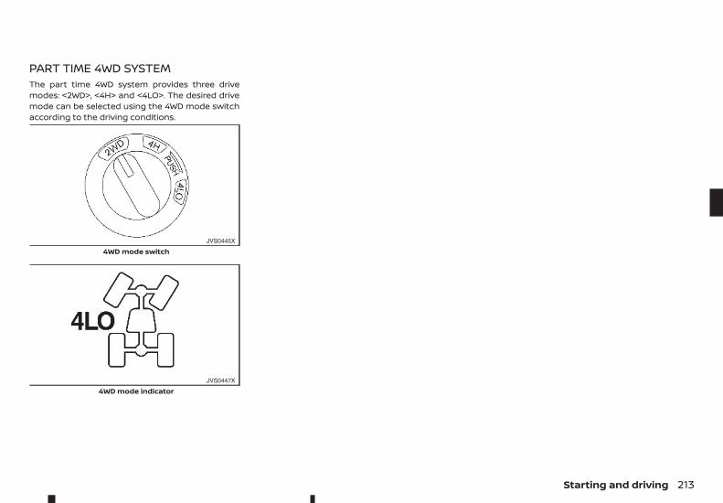
PART TIME 4WD SYSTEMThe part time 4WD system provides three drivemodes: <2WD>, <4H> and <4LO>. The desired drivemode can be selected using the 4WD mode switchaccording to the driving conditions.
JVS0445X
4WD mode switch
JVS0447X
4WD mode indicator
Starting and driving 213
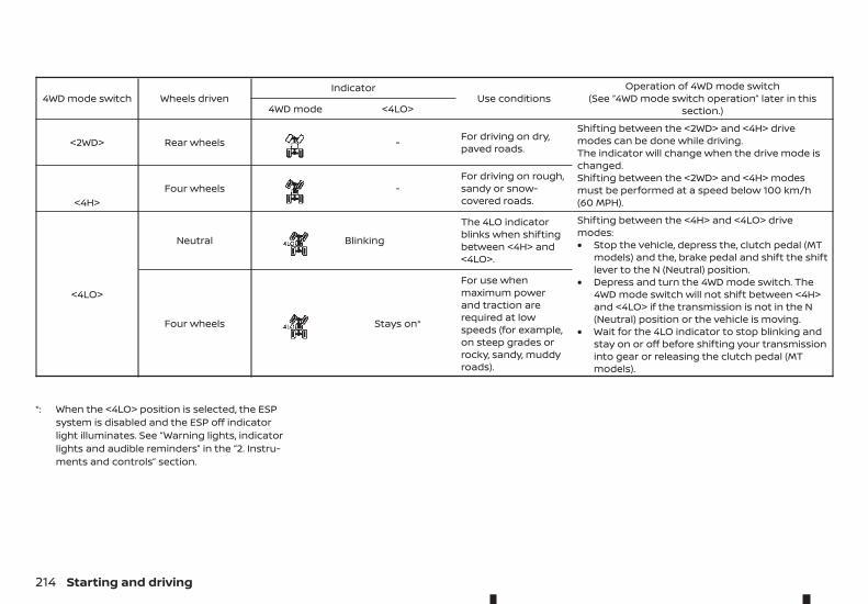
4WD mode switch Wheels drivenIndicator
Use conditionsOperation of 4WD mode switch
(See “4WD mode switch operation” later in thissection.)4WD mode <4LO>
<2WD> Rear wheels m - For driving on dry,paved roads.
Shifting between the <2WD> and <4H> drivemodes can be done while driving.The indicator will change when the drive mode ischanged.Shifting between the <2WD> and <4H> modesmust be performed at a speed below 100 km/h(60 MPH).<4H>
Four wheels m -For driving on rough,sandy or snow-covered roads.
<4LO>
Neutral m Blinking
The 4LO indicatorblinks when shiftingbetween <4H> and<4LO>.
Shifting between the <4H> and <4LO> drivemodes:• Stop the vehicle, depress the, clutch pedal (MT
models) and the, brake pedal and shift the shiftlever to the N (Neutral) position.
• Depress and turn the 4WD mode switch. The4WD mode switch will not shift between <4H>and <4LO> if the transmission is not in the N(Neutral) position or the vehicle is moving.
• Wait for the 4LO indicator to stop blinking andstay on or off before shifting your transmissioninto gear or releasing the clutch pedal (MTmodels).
Four wheels m Stays on*
For use whenmaximum powerand traction arerequired at lowspeeds (for example,on steep grades orrocky, sandy, muddyroads).
*: When the <4LO> position is selected, the ESPsystem is disabled and the ESP off indicatorlight illuminates. See “Warning lights, indicatorlights and audible reminders” in the “2. Instru-ments and controls” section.
214 Starting and driving
WARNINGAT model: If the 4WD mode indicator is “OFF” orthe ATP warning light is “ON”, this indicates thatthe automatic transmission P (Park) position willnot function and could result in the vehicle mov-ing unexpectedly, causing serious personal injuryor property damage. Always set the parkingbrake.
CAUTIONTo avoid vehicle damage:
• Do not operate the 4WD mode switch whencornering, reversing or if the rear wheels arespinning freely. The vehicle must be movingstraight ahead.
• Do not move the shift lever (AT model) or re-lease the clutch pedal (MT model) when the4LO indicator is blinking. Failure to do this maycause the gears to grind and damage the pow-ertrain.
• MT model: Do not accelerate rapidly from astopped position when the 4LO indicator isblinking. Drive straight ahead at a low speeduntil the 4LO indicator is lit. The 4LO indicatorblinks when shifting between <4LO> and<4H>.
• If the 4WD warning light comes on, performthe following procedure:
1) Turn off the engine.
2) Start the engine.
3) Check if the 4WD warning light comes on.
If the 4WD warning light is still on after followingthe above procedure, have the system checkedand serviced immediately by an approved dealeror qualified workshop.
The transfer case 4WD mode switch is used to se-lect either Two-Wheel Drive (2WD) or Four-WheelDrive (4WD) depending on the driving conditions.Turn the 4WD mode switch to select a drive mode(<2WD>, <4H> or <4LO>).
To change into or out of 4LO mode:
1. The vehicle MUST BE standing still.
2. Depress the clutch pedal (MT model) and thebrake pedal and move the shift lever to N (Neu-tral) (MT model) or to the P (Park) position (ATmodel).
3. Depress and turn the 4WD mode switch tochange into or out of <4LO>.
WARNING• When parking, apply the parking brake before
stopping the engine and make sure that the4WD mode indicator is on and that the ATPwarning light or ATP warning message is off,otherwise, the vehicle could unexpectedlymove even if the automatic transmission is inthe P (Park) position.
• The 4LO indicator must stop blinking and re-main on or turn off before shifting the trans-mission into gear. The vehicle may move un-expectedly if the shift lever is shifted from theN (Neutral) position to any other gear while the4LO indicator is blinking.
CAUTION• Never turn the 4WD mode switch between
<4LO> and <4H> while driving.
• The <4H> drive mode provides greater powerand traction. Avoid excessive speed as it willcause increased fuel consumption and higheroil temperatures, and could damage powertrain components. Speeds over 100 km/h (60MPH) in <4H> are not recommended.
• The <4LO> drive mode provides maximumpower and traction. Avoid raising vehiclespeed excessively. The maximum speed is ap-proximately 50 km/h (30 MPH).
• The 4WD mode switch can be turned between<2WD> and <4H> while driving straight ahead.Do not turn the 4WD mode switch while mak-ing a turn or reversing.
• Do not turn the 4WD mode switch between<2WD> and <4H> while driving on steep down-hill grades. Use the engine brake and lowtransmission gears for engine braking.
• Do not turn the 4WD mode switch between<2WD> and <4H> with the rear wheels spin-ning.
• Do not drive the vehicle in <4H> or <4LO> modeon dry, hard surfaced roads. This may causeunnecessary noise and tyre wear. RENAULTrecommends driving in 2WD under these con-ditions.
Starting and driving 215
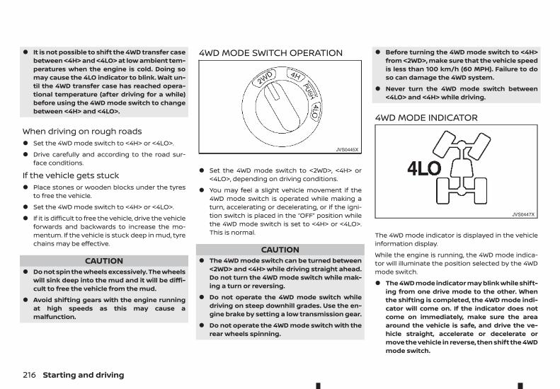
• It is not possible to shift the 4WD transfer casebetween <4H> and <4LO> at low ambient tem-peratures when the engine is cold. Doing somay cause the 4LO indicator to blink. Wait un-til the 4WD transfer case has reached opera-tional temperature (after driving for a while)before using the 4WD mode switch to changebetween <4H> and <4LO>.
When driving on rough roads• Set the 4WD mode switch to <4H> or <4LO>.
• Drive carefully and according to the road sur-face conditions.
If the vehicle gets stuck• Place stones or wooden blocks under the tyres
to free the vehicle.
• Set the 4WD mode switch to <4H> or <4LO>.
• If it is difficult to free the vehicle, drive the vehicleforwards and backwards to increase the mo-mentum. If the vehicle is stuck deep in mud, tyrechains may be effective.
CAUTION• Do not spin the wheels excessively. The wheels
will sink deep into the mud and it will be diffi-cult to free the vehicle from the mud.
• Avoid shifting gears with the engine runningat high speeds as this may cause amalfunction.
4WD MODE SWITCH OPERATION
• Set the 4WD mode switch to <2WD>, <4H> or<4LO>, depending on driving conditions.
• You may feel a slight vehicle movement if the4WD mode switch is operated while making aturn, accelerating or decelerating, or if the igni-tion switch is placed in the “OFF” position whilethe 4WD mode switch is set to <4H> or <4LO>.This is normal.
CAUTION• The 4WD mode switch can be turned between
<2WD> and <4H> while driving straight ahead.Do not turn the 4WD mode switch while mak-ing a turn or reversing.
• Do not operate the 4WD mode switch whiledriving on steep downhill grades. Use the en-gine brake by setting a low transmission gear.
• Do not operate the 4WD mode switch with therear wheels spinning.
• Before turning the 4WD mode switch to <4H>from <2WD>, make sure that the vehicle speedis less than 100 km/h (60 MPH). Failure to doso can damage the 4WD system.
• Never turn the 4WD mode switch between<4LO> and <4H> while driving.
4WD MODE INDICATOR
The 4WD mode indicator is displayed in the vehicleinformation display.
While the engine is running, the 4WD mode indica-tor will illuminate the position selected by the 4WDmode switch.
• The 4WD mode indicator may blink while shift-ing from one drive mode to the other. Whenthe shifting is completed, the 4WD mode indi-cator will come on. If the indicator does notcome on immediately, make sure the areaaround the vehicle is safe, and drive the ve-hicle straight, accelerate or decelerate ormove the vehicle in reverse, then shift the 4WDmode switch.
JVS0445X
JVS0447X
216 Starting and driving
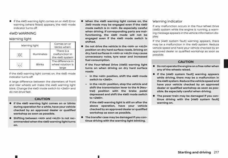
• If the 4WD warning light comes on or 4WD Errorwarning (where fitted) appears, the 4WD modeindicator turns off.
4WD WARNINGWarning light
Warning light Comes on orblinks when:
m IlluminatesThere is a
malfunction inthe 4WD system
m BlinksThe difference inwheel rotation is
large
If the 4WD warning light comes on, the 4WD modeindicator turns off.
A large difference between the diameters of frontand rear wheels will make the 4WD warning lightblink. Change the 4WD mode switch to <2WD> anddo not drive fast.
CAUTION• If the 4WD warning light comes on or blinks
during operation for a while, have your vehiclechecked by an approved dealer or qualifiedworkshop as soon as possible.
• Shifting between <4H> and <4LO> is not rec-ommended when the 4WD warning light turnson.
• When the 4WD warning light comes on, the2WD mode may be engaged even if the 4WDmode switch is in <4H>. Be especially carefulwhen driving. If corresponding parts are mal-functioning, the 4WD mode will not beengaged even if the 4WD mode switch isshifted.
• Do not drive the vehicle in the <4H> or <4LO>position on dry hard surface roads. Driving ondry, hard surfaces in <4H> or <4LO> may causeunnecessary noise, tyre wear and increasedfuel consumption.
If the Four-Wheel Drive (4WD) warning lightturns on when driving on dry hard surfaceroads:
– in the <4H> position, shift the 4WD modeswitch to <2WD>.
– in the <4LO> position, stop the vehicle andshift the transmission lever to the N (Neu-tral) position with the brake pedaldepressed and shift the 4WD mode switchto <2WD>.
If the 4WD warning light is still on after theabove operation, have your vehiclechecked by an approved dealer or qualifiedworkshop as soon as possible.
• The transfer case may be damaged if you con-tinue driving with the warning light blinking.
Warning indicatorIf any malfunction occurs in the Four-Wheel Drive(4WD) system while the engine is running, a warn-ing message appears in the vehicle information dis-play.
If the [4WD system fault] warning appears, theremay be a malfunction in the 4WD system. Reducevehicle speed and have your vehicle checked by anapproved dealer or qualified workshop as soon aspossible.
CAUTION• Do not operate the engine on a free roller when
any of the wheels raised.
• If the [4WD system fault] warning appearswhile driving, there may be a malfunction inthe 4WD system. Reduce the vehicle speed andhave your vehicle checked by an approveddealer or qualified workshop as soon as pos-sible. Be especially careful when driving.
• The power train may be damaged if you con-tinue driving with the [4WD system fault]warning on.
Starting and driving 217
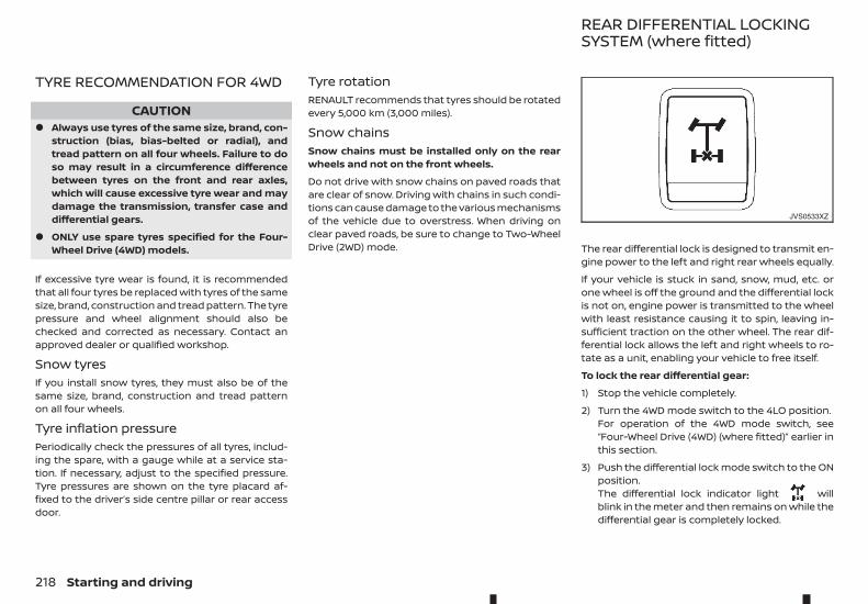
TYRE RECOMMENDATION FOR 4WD
CAUTION• Always use tyres of the same size, brand, con-
struction (bias, bias-belted or radial), andtread pattern on all four wheels. Failure to doso may result in a circumference differencebetween tyres on the front and rear axles,which will cause excessive tyre wear and maydamage the transmission, transfer case anddifferential gears.
• ONLY use spare tyres specified for the Four-Wheel Drive (4WD) models.
If excessive tyre wear is found, it is recommendedthat all four tyres be replaced with tyres of the samesize, brand, construction and tread pattern. The tyrepressure and wheel alignment should also bechecked and corrected as necessary. Contact anapproved dealer or qualified workshop.
Snow tyresIf you install snow tyres, they must also be of thesame size, brand, construction and tread patternon all four wheels.
Tyre inflation pressurePeriodically check the pressures of all tyres, includ-ing the spare, with a gauge while at a service sta-tion. If necessary, adjust to the specified pressure.Tyre pressures are shown on the tyre placard af-fixed to the driver’s side centre pillar or rear accessdoor.
Tyre rotationRENAULT recommends that tyres should be rotatedevery 5,000 km (3,000 miles).
Snow chainsSnow chains must be installed only on the rearwheels and not on the front wheels.
Do not drive with snow chains on paved roads thatare clear of snow. Driving with chains in such condi-tions can cause damage to the various mechanismsof the vehicle due to overstress. When driving onclear paved roads, be sure to change to Two-WheelDrive (2WD) mode. The rear differential lock is designed to transmit en-
gine power to the left and right rear wheels equally.
If your vehicle is stuck in sand, snow, mud, etc. orone wheel is off the ground and the differential lockis not on, engine power is transmitted to the wheelwith least resistance causing it to spin, leaving in-sufficient traction on the other wheel. The rear dif-ferential lock allows the left and right wheels to ro-tate as a unit, enabling your vehicle to free itself.
To lock the rear differential gear:
1) Stop the vehicle completely.
2) Turn the 4WD mode switch to the 4LO position.For operation of the 4WD mode switch, see“Four-Wheel Drive (4WD) (where fitted)” earlier inthis section.
3) Push the differential lock mode switch to the ONposition.The differential lock indicator light willblink in the meter and then remains on while thedifferential gear is completely locked.
JVS0533XZ
REAR DIFFERENTIAL LOCKINGSYSTEM (where fitted)
218 Starting and driving
After using the rear differential lock, or when resum-ing normal driving, push the differential lock modeswitch to the OFF position. The differential lock indi-cator light will turn off after the differential lock isreleased.
NOTE
• The rear differential lock-up device operatesonly when the engine is running.
• In 4H mode, the rear differential lock-up de-vice does not operate when the differentiallock mode switch is turned to the “ON” posi-tion. (The differential lock indicator light willflash.)
WARNING• Use the rear differential lock only in an emer-
gency when it is not possible to free a stuckvehicle even using the 4LO position.
• When the differential lock is in operation, turn-ing the vehicle becomes hard and, especiallyat high speeds, is dangerous.
• While differential lock is on, the Anti-lock Brak-ing System (ABS) warning light and the Elec-tronic Stability Programme (ESP) off indicatorlight illuminate. This indicates that anti-lockfunction may not fully operate.
• Do not operate the differential lock when thevehicle is turning or when one side wheel isrotating. Otherwise the power train systemparts could be damaged.
• Avoid quick starts while the differential lock isin operation. Otherwise the power train sys-tem parts could be damaged.
Observe the above precautions. Otherwise, lossof normal steering control may result.
WARNING• The Electronic Stability Programme (ESP) sys-
tem is designed to help the driver maintainstability but does not prevent accidents dueto abrupt steering operation at high speeds orby careless or dangerous driving techniques.Reduce vehicle speed and be especially care-ful when driving and cornering on slipperysurfaces and always drive carefully.
• Do not modify the vehicle’s suspension. If sus-pension parts such as shock absorbers, struts,springs, stabiliser bars, bushings and wheelsare not recommended by RENAULT for yourvehicle or are extremely deteriorated, the ESPsystem may not operate properly. This couldadversely affect vehicle handling perfor-mance, and the ESP warning light may il-luminate.
• If brake related parts such as brake pads, ro-tors and callipers are not RENAULT-recom-mended or are extremely deteriorated, theESP system may not operate properly and theESP warning light may illuminate.
• If engine control related parts are not RENAULTrecommended or are extremely deteriorated,the ESP warning light may illuminate.
• When driving on extremely inclined surfacessuch as higher banked corners, the ESP sys-tem may not operate properly and the ESPwarning light may illuminate. Do not driveon these types of roads.
ELECTRONIC STABILITYPROGRAMME (ESP) SYSTEM(where fitted)
Starting and driving 219
• When driving on an unstable surface such as aturntable, ferry, elevator or ramp, the ESPwarning light may illuminate. This is not amalfunction. Restart the engine after drivingonto a stable surface.
• If wheels or tyres other than the RENAULT rec-ommended ones are used, the ESP systemmay not operate properly and the ESP warn-ing light may illuminate.
• The ESP system is not a substitute for wintertyres or tyre chains on a snow covered road.
The Electronic Stability Programme (ESP) systemuses various sensors to monitor driver inputs andvehicle motion. Under certain driving conditions, theESP system performs the following functions:
• Controls brake pressure to reduce wheel slip onone slipping drive wheel so power is transferredto a non slipping drive wheel on the same axle.
• Controls brake pressure and engine output toreduce drive wheel slip based on vehicle speed(traction control function).
• Controls brake pressure at individual wheels andengine output to help the driver maintain con-trol of the vehicle in the following conditions:
– understeer (vehicle tends to not follow thesteered path despite increased steering in-put)
– oversteer (vehicle tends to spin due to cer-tain road or driving conditions).
The ESP system can help the driver to maintain con-trol of the vehicle, but it cannot prevent loss of ve-hicle control in all driving situations.
When the ESP system operates, the ESP warninglight in the instrument panel flashes so notethe following:
• The road may be slippery or the system may de-termine some action is required to help the ve-hicle on the steered path.
• You may feel a pulsation in the brake pedal andhear a noise or vibration from under the bonnet.This is normal and indicates that the ESP systemis working properly.
• Adjust your speed and driving to the road condi-tions.
If a malfunction occurs in the system, the ESP warn-ing light illuminates in the instrument panel.The ESP system automatically turns off.
The ESP OFF switch is used to turn off the ESP sys-tem. The ESP off indicator light illuminates toindicate the ESP system is off. When the ESP OFFswitch is used to turn off the system, the ESP sys-tem still operates to prevent one drive wheel fromslipping by transferring power to a non slippingdrive wheel. The ESP warning light flashes ifthis occurs. All other ESP functions are off and theESP warning light will not flash. The ESP systemis automatically reset to on when the ignition switchis placed in the OFF position then back to the ONposition.
When the <4LO> position is selected with the Four-Wheel Drive (4WD) mode switch, the ESP system isdisabled and the ESP OFF indicator light illuminates.
See “Warning lights, indicator lights and audiblereminders” in the “2. Instruments and controls” sec-tion and “Four-Wheel Drive (4WD) (where fitted)” ear-lier in this section.
The computer has a built-in diagnostic feature thattests the system each time you start the engineand move the vehicle forward or in reverse at a slowspeed. When the self-test occurs, you may hear a“clunk” noise and/or feel a pulsation in the brakepedal. This is normal and is not an indication of amalfunction.
TRAILER SWAY ASSIST (TSA)SYSTEM (where fitted)If your vehicle trailer combination begins to lurch,the Trailer Sway Assist (TSA) system assists you inthis situation. The TSA system slows the vehicledown by braking and limiting the engine output un-til the vehicle/trailer combination has stabilised.
WARNINGIf road and weather conditions are poor, trailerstabilisation will not be able to prevent the ve-hicle/trailer combination from swerving. Trailerswith a high centre of gravity can tip over beforethe TSA system can detect this. There is a risk ofan accident.
Always adapt your driving style to the prevailingroad and weather conditions.
If your vehicle/trailer combination begins to lurch,you can only stabilise the vehicle/trailer combina-tion by depressing the brake.
The system is active above speeds of approximately65 km/h.
The system does not work if ESP is deactivated ordisabled because of a malfunction.
220 Starting and driving
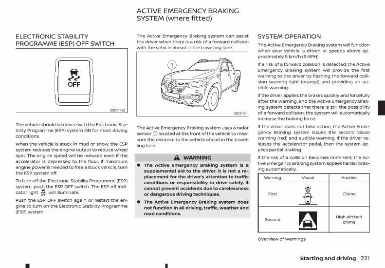
ELECTRONIC STABILITYPROGRAMME (ESP) OFF SWITCH
The vehicle should be driven with the Electronic Sta-bility Programme (ESP) system ON for most drivingconditions.
When the vehicle is stuck in mud or snow, the ESPsystem reduces the engine output to reduce wheelspin. The engine speed will be reduced even if theaccelerator is depressed to the floor. If maximumengine power is needed to free a stuck vehicle, turnthe ESP system off.
To turn off the Electronic Stability Programme (ESP)system, push the ESP OFF switch. The ESP off indi-cator light will illuminate.
Push the ESP OFF switch again or restart the en-gine to turn on the Electronic Stability Programme(ESP) system.
The Active Emergency Braking system can assistthe driver when there is a risk of a forward collisionwith the vehicle ahead in the travelling lane.
The Active Emergency Braking system uses a radarsensor ➀ located at the front of the vehicle to mea-sure the distance to the vehicle ahead in the travel-ling lane.
WARNING• The Active Emergency Braking system is a
supplemental aid to the driver. It is not a re-placement for the driver’s attention to trafficconditions or responsibility to drive safely. Itcannot prevent accidents due to carelessnessor dangerous driving techniques.
• The Active Emergency Braking system doesnot function in all driving, traffic, weather androad conditions.
SYSTEM OPERATIONThe Active Emergency Braking system will functionwhen your vehicle is driven at speeds above ap-proximately 5 km/h (3 MPH).
If a risk of a forward collision is detected, the ActiveEmergency Braking system will provide the firstwarning to the driver by flashing the forward colli-sion warning light (orange) and providing an au-dible warning.
If the driver applies the brakes quickly and forcefullyafter the warning, and the Active Emergency Brak-ing system detects that there is still the possibilityof a forward collision, the system will automaticallyincrease the braking force.
If the driver does not take action, the Active Emer-gency Braking system issues the second visualwarning (red) and audible warning. If the driver re-leases the accelerator pedal, then the system ap-plies partial braking
If the risk of a collision becomes imminent, the Ac-tive Emergency Braking system applies harder brak-ing automatically.
Warning Visual Audible
First m Chime
Second m High pitchedchime
Overview of warnings
SSD1149ZNIC3103
ACTIVE EMERGENCY BRAKINGSYSTEM (where fitted)
Starting and driving 221
NOTE
The vehicle’s brake lights come on when brakingis performed by the Active Emergency Brakingsystem.
Depending on vehicle speed and distance to the ve-hicle ahead, as well as driving and roadway condi-tions, the system may help the driver avoid a for-ward collision or may help mitigate theconsequences if a collision should one be unavoid-able.
If the driver is handling the steering wheel, acceler-ating or braking, the Active Emergency Braking sys-tem will function later or will not function.
The automatic braking will cease under the follow-ing conditions:
• When the steering wheel is turned as far as nec-essary to avoid a collision.
• When the accelerator pedal is depressed.
• When there is no longer a vehicle detectedahead.
If the Active Emergency Braking system hasstopped the vehicle, the vehicle will remain at astandstill for approximately 2 seconds before thebrakes are released.
WARNING• The radar sensor does not detect the follow-
ing objects:
– Pedestrians, animals or obstacles in theroadway
– Oncoming vehicles
– Crossing vehicles
• The radar sensor has some performance limi-tations. If a stationary vehicle is in the vehi-cle's path, the Active Emergency Braking sys-tem will not function when the vehicle is drivenat speeds over approximately 70 km/h (44MPH).
• The radar sensor may not detect a vehicleahead in the following conditions:
– Dirt, ice, snow or other material coveringthe radar sensor.
– Interference by other radar sources.
– Snow or road spray from travellingvehicles.
– If the vehicle ahead is narrow (e.g. motor-cycle).
– When driving on a steep downhill slope orroads with sharp curves.
– When towing a trailer.
• In some road or traffic conditions, the ActiveEmergency Braking system may unexpect-edly apply partial braking. When accelerationis necessary, continue to depress the accelera-tor pedal to override the system.
• Braking distances increase on slipperysurfaces.
• Excessive noise will interfere with the warningchime sound, and the chime may not be heard.
• The system is designed to automaticallycheck the sensor's functionality, within cer-tain limitations. The system may not detectsome forms of obstruction of the sensor areaof the front bumper such as ice, snow, stickers,for example. In these cases, the system maynot be able to warn the driver properly. Be surethat you check, clean and clear the sensor areaof the front bumper regularly
Turning the Active Emergency Brakingsystem ON/OFFPerform the following steps to turn the Active Emer-gency Braking system ON or OFF.
Models with colour display:1. Using the or switches and the <ENTER> but-
ton on the left side of the steering wheel, selectthe Settings menu in the vehicle information dis-play. (See “Vehicle information display” in the“2. Instruments and controls” section
2. Using the or switches and the <ENTER> but-ton, navigate to the [Driver Assistance] menu, fol-lowed by the [Driving Aids] menu.
3. In the [Driving Aids] menu, highlight the [Emer-gency Brake] item and use the <ENTER> buttonto toggle between ON (enabled) or OFF(disabled).
222 Starting and driving
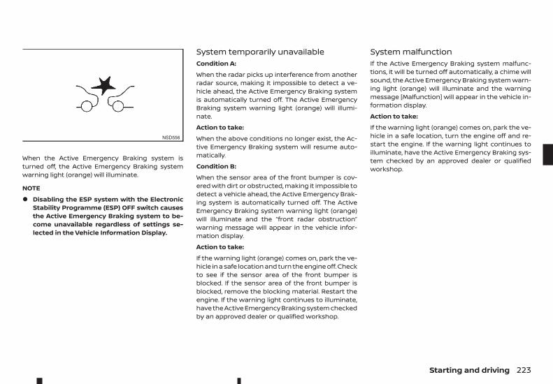
When the Active Emergency Braking system isturned off, the Active Emergency Braking systemwarning light (orange) will illuminate.
NOTE
• Disabling the ESP system with the ElectronicStability Programme (ESP) OFF switch causesthe Active Emergency Braking system to be-come unavailable regardless of settings se-lected in the Vehicle Information Display.
System temporarily unavailableCondition A:
When the radar picks up interference from anotherradar source, making it impossible to detect a ve-hicle ahead, the Active Emergency Braking systemis automatically turned off. The Active EmergencyBraking system warning light (orange) will illumi-nate.
Action to take:
When the above conditions no longer exist, the Ac-tive Emergency Braking system will resume auto-matically.
Condition B:
When the sensor area of the front bumper is cov-ered with dirt or obstructed, making it impossible todetect a vehicle ahead, the Active Emergency Brak-ing system is automatically turned off. The ActiveEmergency Braking system warning light (orange)will illuminate and the “front radar obstruction”warning message will appear in the vehicle infor-mation display.
Action to take:
If the warning light (orange) comes on, park the ve-hicle in a safe location and turn the engine off. Checkto see if the sensor area of the front bumper isblocked. If the sensor area of the front bumper isblocked, remove the blocking material. Restart theengine. If the warning light continues to illuminate,have the Active Emergency Braking system checkedby an approved dealer or qualified workshop.
System malfunctionIf the Active Emergency Braking system malfunc-tions, it will be turned off automatically, a chime willsound, the Active Emergency Braking system warn-ing light (orange) will illuminate and the warningmessage [Malfunction] will appear in the vehicle in-formation display.
Action to take:
If the warning light (orange) comes on, park the ve-hicle in a safe location, turn the engine off and re-start the engine. If the warning light continues toilluminate, have the Active Emergency Braking sys-tem checked by an approved dealer or qualifiedworkshop.
NSD556
Starting and driving 223
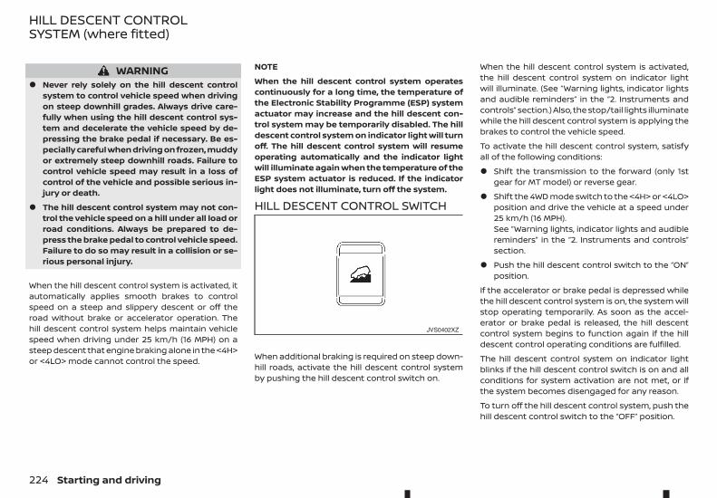
WARNING• Never rely solely on the hill descent control
system to control vehicle speed when drivingon steep downhill grades. Always drive care-fully when using the hill descent control sys-tem and decelerate the vehicle speed by de-pressing the brake pedal if necessary. Be es-pecially careful when driving on frozen, muddyor extremely steep downhill roads. Failure tocontrol vehicle speed may result in a loss ofcontrol of the vehicle and possible serious in-jury or death.
• The hill descent control system may not con-trol the vehicle speed on a hill under all load orroad conditions. Always be prepared to de-press the brake pedal to control vehicle speed.Failure to do so may result in a collision or se-rious personal injury.
When the hill descent control system is activated, itautomatically applies smooth brakes to controlspeed on a steep and slippery descent or off theroad without brake or accelerator operation. Thehill descent control system helps maintain vehiclespeed when driving under 25 km/h (16 MPH) on asteep descent that engine braking alone in the <4H>or <4LO> mode cannot control the speed.
NOTE
When the hill descent control system operatescontinuously for a long time, the temperature ofthe Electronic Stability Programme (ESP) systemactuator may increase and the hill descent con-trol system may be temporarily disabled. The hilldescent control system on indicator light will turnoff. The hill descent control system will resumeoperating automatically and the indicator lightwill illuminate again when the temperature of theESP system actuator is reduced. If the indicatorlight does not illuminate, turn off the system.
HILL DESCENT CONTROL SWITCH
When additional braking is required on steep down-hill roads, activate the hill descent control systemby pushing the hill descent control switch on.
When the hill descent control system is activated,the hill descent control system on indicator lightwill illuminate. (See “Warning lights, indicator lightsand audible reminders” in the “2. Instruments andcontrols” section.) Also, the stop/tail lights illuminatewhile the hill descent control system is applying thebrakes to control the vehicle speed.
To activate the hill descent control system, satisfyall of the following conditions:
• Shift the transmission to the forward (only 1stgear for MT model) or reverse gear.
• Shift the 4WD mode switch to the <4H> or <4LO>position and drive the vehicle at a speed under25 km/h (16 MPH).See “Warning lights, indicator lights and audiblereminders” in the “2. Instruments and controls”section.
• Push the hill descent control switch to the “ON”position.
If the accelerator or brake pedal is depressed whilethe hill descent control system is on, the system willstop operating temporarily. As soon as the accel-erator or brake pedal is released, the hill descentcontrol system begins to function again if the hilldescent control operating conditions are fulfilled.
The hill descent control system on indicator lightblinks if the hill descent control switch is on and allconditions for system activation are not met, or ifthe system becomes disengaged for any reason.
To turn off the hill descent control system, push thehill descent control switch to the “OFF” position.
JVS0402XZ
HILL DESCENT CONTROLSYSTEM (where fitted)
224 Starting and driving
WARNING• Never rely solely on the hill start assist system
to prevent the vehicle from moving backwardon a hill. Always drive carefully and attentively.Depress the brake pedal when the vehicle isstopped on a steep hill. Be especially carefulwhen stopped on a hill on frozen or muddyroads. Failure to prevent the vehicle from roll-ing backwards may result in a loss of controlof the vehicle and possible serious injury ordeath.
• The hill start assist system is not designed tohold the vehicle at a standstill on a hill. De-press the brake pedal when the vehicle isstopped on a steep hill. Failure to do so maycause the vehicle to roll backwards and mayresult in a collision or serious personal injury.
• The hill start assist system may not preventthe vehicle from rolling backwards on a hill un-der all load or road conditions. Always be pre-pared to depress the brake pedal to preventthe vehicle from rolling backwards. Failure todo so may result in a collision or serious per-sonal injury.
The hill start assist system automatically keeps thebrakes applied to help prevent the vehicle from roll-ing backwards in the time it takes the driver to re-lease the brake pedal and apply the acceleratorwhen the vehicle is stopped on a hill.
The hill start assist system will operate automati-cally under the following conditions:
• The transmission is shifted to a forward or re-verse gear.
• The vehicle is stopped completely on a hill byapplying the brake.
The maximum holding time is 2 seconds. After 2seconds the vehicle will begin to roll back and thehill start assist system will stop operatingcompletely.
The hill start assist system will not operate whenthe transmission is shifted to the N (Neutral) or P(Park) position or on a flat and level road.
When the Electronic Stability Programme (ESP)warning light illuminates in the meter, the hill startassist system will not operate. (See “Electronic Sta-bility Programme (ESP) system (where fitted)” ear-lier in this section.)
The cruise control system allows driving at constantspeeds without keeping your foot on the accelera-tor pedal.
WARNING• The cruise control system ONLY maintains a
constant vehicle speed, it does not replace thedriver.
• Always observe the posted speed limits anddo not set the speed over them.
• Do not use the cruise control when driving un-der the following conditions. Doing so couldcause a loss of vehicle control and result in anaccident.
– When it is not possible to keep the vehicleat a constant speed
– When driving in heavy traffic
– When driving in traffic that varies speed
– When driving in windy areas
– When driving on winding or hilly roads
– When driving on slippery (rain, snow, ice,etc.) roads
CAUTIONOn manual Transmission (MT) model, do not shiftto the N (Neutral) position without depressing theclutch pedal when the cruise control is operated.Should this occur, depress the clutch pedal andturn the cruise control MAIN switch off immedi-ately. Failure to do so may cause engine damage.
HILL START ASSIST SYSTEM(where fitted)
CRUISE CONTROL (where fitted)
Starting and driving 225
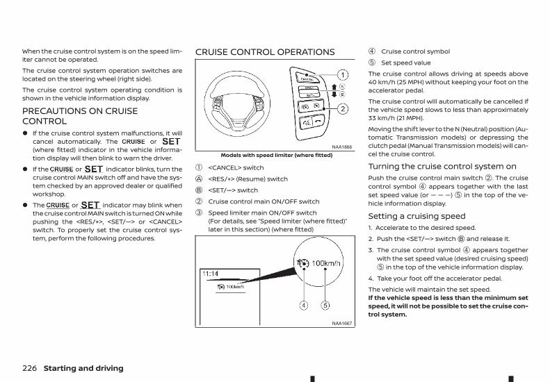
When the cruise control system is on the speed lim-iter cannot be operated.
The cruise control system operation switches arelocated on the steering wheel (right side).
The cruise control system operating condition isshown in the vehicle information display.
PRECAUTIONS ON CRUISECONTROL• If the cruise control system malfunctions, it will
cancel automatically. The or(where fitted) indicator in the vehicle informa-tion display will then blink to warn the driver.
• If the or indicator blinks, turn thecruise control MAIN switch off and have the sys-tem checked by an approved dealer or qualifiedworkshop.
• The or indicator may blink whenthe cruise control MAIN switch is turned ON whilepushing the <RES/+>, <SET/—> or <CANCEL>switch. To properly set the cruise control sys-tem, perform the following procedures.
CRUISE CONTROL OPERATIONS
➀ <CANCEL> switchjA <RES/+> (Resume) switchjB <SET/—> switch
➁ Cruise control main ON/OFF switch
➂ Speed limiter main ON/OFF switch(For details, see “Speed limiter (where fitted)”later in this section) (where fitted)
➃ Cruise control symbol
➄ Set speed value
The cruise control allows driving at speeds above40 km/h (25 MPH) without keeping your foot on theaccelerator pedal.
The cruise control will automatically be cancelled ifthe vehicle speed slows to less than approximately33 km/h (21 MPH).
Moving the shift lever to the N (Neutral) position (Au-tomatic Transmission models) or depressing theclutch pedal (Manual Transmission models) will can-cel the cruise control.
Turning the cruise control system onPush the cruise control main switch ➁. The cruisecontrol symbol ➃ appears together with the lastset speed value (or — — —) ➄ in the top of the ve-hicle information display.
Setting a cruising speed1. Accelerate to the desired speed.
2. Push the <SET/—> switchjB and release it.
3. The cruise control symbol ➃ appears togetherwith the set speed value (desired cruising speed)➄ in the top of the vehicle information display.
4. Take your foot off the accelerator pedal.
The vehicle will maintain the set speed.If the vehicle speed is less than the minimum setspeed, it will not be possible to set the cruise con-trol system.
NAA1866
Models with speed limiter (where fitted)
NAA1667
226 Starting and driving
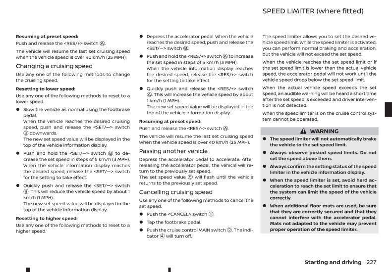
Resuming at preset speed:Push and release the <RES/+> switchjA .
The vehicle will resume the last set cruising speedwhen the vehicle speed is over 40 km/h (25 MPH).
Changing a cruising speedUse any one of the following methods to changethe cruising speed.
Resetting to lower speed:Use any one of the following methods to reset to alower speed.
• Slow the vehicle as normal using the footbrakepedal.When the vehicle reaches the desired cruisingspeed, push and release the <SET/—> switchjB downwards.The new set speed value will be displayed in thetop of the vehicle information display.
• Push and hold the <SET/—> switch jB to de-crease the set speed in steps of 5 km/h (3 MPH).When the vehicle information display reachesthe desired speed, release the <SET/—> switchfor the setting to take effect.
• Quickly push and release the <SET/—> switchjB . This will reduce the vehicle speed by about 1km/h (1 MPH).The new set speed value will be displayed in thetop of the vehicle information display.
Resetting to higher speed:Use any one of the following methods to reset to ahigher speed.
• Depress the accelerator pedal. When the vehiclereaches the desired speed, push and release the<SET/—> switchjB .
• Push and hold the <RES/+> switchjA to increasethe set speed in steps of 5 km/h (3 MPH).When the vehicle information display reachesthe desired speed, release the <RES/+> switchfor the setting to take effect.
• Quickly push and release the <RES/+> switchjA . This will increase the vehicle speed by about1 km/h (1 MPH).The new set speed value will be displayed in thetop of the vehicle information display.
Resuming at preset speed:Push and release the <RES/+> switchjA .
The vehicle will resume the last set cruising speedwhen the vehicle speed is over 40 km/h (25 MPH).
Passing another vehicleDepress the accelerator pedal to accelerate. Afterreleasing the accelerator pedal, the vehicle will re-turn to the previously set speed.The set speed value ➄ will flash until the vehiclereturns to the previously set speed.
Cancelling cruising speedUse any one of the following methods to cancel theset speed.
• Push the <CANCEL> switch ➀.
• Tap the footbrake pedal.
• Push the cruise control MAIN switch ➁. The indi-cator ➃ will turn off.
The speed limiter allows you to set the desired ve-hicle speed limit. While the speed limiter is activated,you can perform normal braking and acceleration,but the vehicle will not exceed the set speed.
When the vehicle reaches the set speed limit or ifthe set speed limit is lower than the actual vehiclespeed, the accelerator pedal will not work until thevehicle speed drops below the set speed limit.
When the actual vehicle speed exceeds the setspeed, an audible warning will be heard a short timeafter the set speed is exceeded and driver interven-tion is not detected.
When the speed limiter is on the cruise control sys-tem cannot be operated.
WARNING• The speed limiter will not automatically brake
the vehicle to the set speed limit.
• Always observe posted speed limits. Do notset the speed above them.
• Always confirm the setting status of the speedlimiter in the vehicle information display.
• When the speed limiter is set, avoid hard ac-celeration to reach the set limit to ensure thatthe system can limit the speed of the vehiclecorrectly.
• When additional floor mats are used, be surethat they are correctly secured and that theycannot interfere with the accelerator pedal.Mats not adapted to the vehicle may preventproper operation of the speed limiter.
SPEED LIMITER (where fitted)
Starting and driving 227
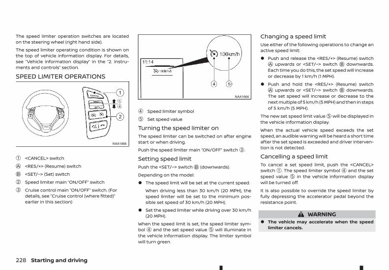
The speed limiter operation switches are locatedon the steering wheel (right hand side).
The speed limiter operating condition is shown onthe top of vehicle information display. For details,see “Vehicle information display” in the “2. Instru-ments and controls” section.
SPEED LIMITER OPERATIONS
➀ <CANCEL> switchjA <RES/+> (Resume) switchjB <SET/–> (Set) switch
➁ Speed limiter main “ON/OFF” switch
➂ Cruise control main “ON/OFF” switch. (Fordetails, see “Cruise control (where fitted)”earlier in this section)
➃ Speed limiter symbol
➄ Set speed value
Turning the speed limiter onThe speed limiter can be switched on after enginestart or when driving.
Push the speed limiter main “ON/OFF” switch ➂.
Setting speed limitPush the <SET/–> switchjB (downwards).
Depending on the model:
• The speed limit will be set at the current speed.
When driving less than 30 km/h (20 MPH), thespeed limiter will be set to the minimum pos-sible set speed of 30 km/h (20 MPH).
• Set the speed limiter while driving over 30 km/h(20 MPH).
When the speed limit is set, the speed limiter sym-bol ➃ and the set speed value ➄ will illuminate inthe vehicle information display. The limiter symbolwill turn green.
Changing a speed limitUse either of the following operations to change anactive speed limit:
• Push and release the <RES/+> (Resume) switchjA upwards or <SET/–> switch jB downwards.Each time you do this, the set speed will increaseor decrease by 1 km/h (1 MPH).
• Push and hold the <RES/+> (Resume) switchjA upwards or <SET/–> switch jB downwards.The set speed will increase or decrease to thenext multiple of 5 km/h (5 MPH) and then in stepsof 5 km/h (5 MPH).
The new set speed limit value ➄ will be displayed inthe vehicle information display.
When the actual vehicle speed exceeds the setspeed, an audible warning will be heard a short timeafter the set speed is exceeded and driver interven-tion is not detected.
Cancelling a speed limitTo cancel a set speed limit, push the <CANCEL>switch ➀. The speed limiter symbol ➃ and the setspeed value ➄ in the vehicle information displaywill be turned off.
It is also possible to override the speed limiter byfully depressing the accelerator pedal beyond theresistance point.
WARNING• The vehicle may accelerate when the speed
limiter cancels.
NAA1866
NAA1666
228 Starting and driving
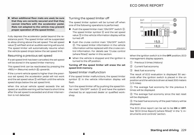
• When additional floor mats are used, be surethat they are correctly secured and that theycannot interfere with the accelerator pedal.Mats not adapted to the vehicle may preventproper operation of the speed limiter.
Fully depress the accelerator pedal beyond the re-sistance point. The speed limiter will be suspendedto allow driving above the set speed. The set speedvalue ➄ will flash and an audible warning will sound.The speed limiter will automatically resume whenthe vehicle speed drops below the set speed limit.
Resuming a previous set speedIf a set speed limit has been cancelled, the set speedwill be stored in the speed limiter memory.
This speed limit can be reactivated by pressing the<RES/+> (Resume) switchjA upwards.
If the current vehicle speed is higher than the previ-ous set speed, the accelerator pedal will not workand the set speed value ➄ will flash until the vehiclespeed drops below the set speed limit.
When the actual vehicle speed exceeds the setspeed, an audible warning will be heard a short timeafter the set speed is exceeded and driver interven-tion is not detected.
Turning the speed limiter offThe speed limiter system will be turned off whenone of the following operations is performed:
• Push the speed limiter main “ON/OFF” switch ➂.The speed limiter symbol ➃ and the set speedvalue ➄ in the vehicle information display will beturned off.
• Push the cruise control main “ON/OFF” switch➁. The speed limiter information in the vehicleinformation will be replaced with the cruise con-trol information. For details see “Cruise control(where fitted)” earlier in this section.
• When the vehicle is stopped and the ignition isturned to the off position.
Turning off the speed limiter will erase the setspeed limit memory.
Speed limiter malfunctionIf the speed limiter malfunctions, the speed limitersymbol ➃ in the vehicle information display willflash.
Turn the speed limiter off by pushing the speed lim-iter main “ON/OFF” switch ➂ and have the systemchecked by an approved dealer or qualified work-shop.
When the ignition switch is in the OFF position, ECOmanagement display appears.
➀ Previous 5 times (History)
➁ Current fuel economy
➂ Best fuel economy
The result of ECO evaluation is displayed 30 sec-onds after the ignition switch is placed in the onposition and the vehicle is driven at least 500 meters(1/3 miles).
➀: The average fuel economy for the previous 5times will be displayed.
➁: The average fuel economy since the last resetwill be displayed.
➂: The best fuel economy of the past history will bedisplayed.
The ECO drive report can be set to be ON or OFF.See “[ECO Drive Report] (where fitted)” in the “2. In-struments and controls” section.
JVS0451XZ
ECO DRIVE REPORT
Starting and driving 229
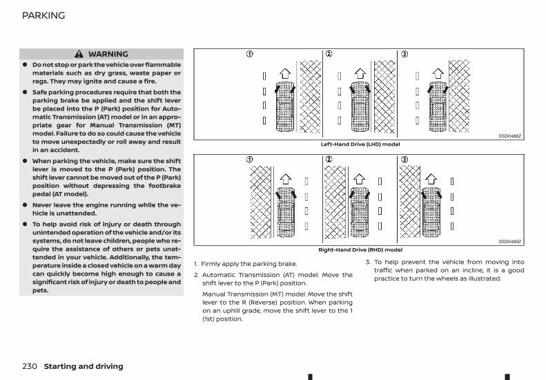
WARNING• Do not stop or park the vehicle over flammable
materials such as dry grass, waste paper orrags. They may ignite and cause a fire.
• Safe parking procedures require that both theparking brake be applied and the shift leverbe placed into the P (Park) position for Auto-matic Transmission (AT) model or in an appro-priate gear for Manual Transmission (MT)model. Failure to do so could cause the vehicleto move unexpectedly or roll away and resultin an accident.
• When parking the vehicle, make sure the shiftlever is moved to the P (Park) position. Theshift lever cannot be moved out of the P (Park)position without depressing the footbrakepedal (AT model).
• Never leave the engine running while the ve-hicle is unattended.
• To help avoid risk of injury or death throughunintended operation of the vehicle and/or itssystems, do not leave children, people who re-quire the assistance of others or pets unat-tended in your vehicle. Additionally, the tem-perature inside a closed vehicle on a warm daycan quickly become high enough to cause asignificant risk of injury or death to people andpets.
1. Firmly apply the parking brake.
2. Automatic Transmission (AT) model: Move theshift lever to the P (Park) position.
Manual Transmission (MT) model: Move the shiftlever to the R (Reverse) position. When parkingon an uphill grade, move the shift lever to the 1(1st) position.
3. To help prevent the vehicle from moving intotraffic when parked on an incline, it is a goodpractice to turn the wheels as illustrated.
SSD0488Z
Left-Hand Drive (LHD) model
SSD0489Z
Right-Hand Drive (RHD) model
PARKING
230 Starting and driving
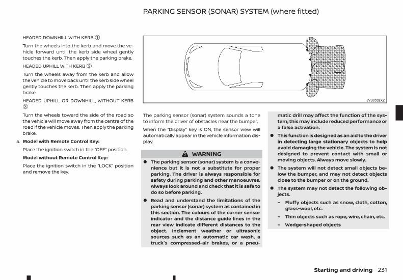
HEADED DOWNHILL WITH KERB ➀Turn the wheels into the kerb and move the ve-hicle forward until the kerb side wheel gentlytouches the kerb. Then apply the parking brake.
HEADED UPHILL WITH KERB ➁Turn the wheels away from the kerb and allowthe vehicle to move back until the kerb side wheelgently touches the kerb. Then apply the parkingbrake.
HEADED UPHILL OR DOWNHILL, WITHOUT KERB➂Turn the wheels toward the side of the road sothe vehicle will move away from the centre of theroad if the vehicle moves. Then apply the parkingbrake.
4. Model with Remote Control Key:
Place the ignition switch in the “OFF” position.
Model without Remote Control Key:
Place the ignition switch in the “LOCK” positionand remove the key.
The parking sensor (sonar) system sounds a toneto inform the driver of obstacles near the bumper.
When the “Display” key is ON, the sensor view willautomatically appear in the vehicle information dis-play.
WARNING• The parking sensor (sonar) system is a conve-
nience but it is not a substitute for properparking. The driver is always responsible forsafety during parking and other manoeuvres.Always look around and check that it is safe todo so before parking.
• Read and understand the limitations of theparking sensor (sonar) system as contained inthis section. The colours of the corner sensorindicator and the distance guide lines in therear view indicate different distances to theobject. Inclement weather or ultrasonicsources such as an automatic car wash, atruck's compressed-air brakes, or a pneu-
matic drill may affect the function of the sys-tem; this may include reduced performance ora false activation.
• This function is designed as an aid to the driverin detecting large stationary objects to helpavoid damaging the vehicle. The system is notdesigned to prevent contact with small ormoving objects. Always move slowly.
• The system will not detect small objects be-low the bumper, and may not detect objectsclose to the bumper or on the ground.
• The system may not detect the following ob-jects.
– Fluffy objects such as snow, cloth, cotton,glass-wool, etc.
– Thin objects such as rope, wire, chain, etc.
– Wedge-shaped objects
JVS0532XZ
PARKING SENSOR (SONAR) SYSTEM (where fitted)
Starting and driving 231
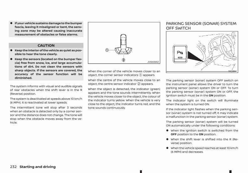
• If your vehicle sustains damage to the bumperfascia, leaving it misaligned or bent, the sens-ing zone may be altered causing inaccuratemeasurement of obstacles or false alarms.
CAUTION• Keep the interior of the vehicle as quiet as pos-
sible to hear the tone clearly.
• Keep the sensors (located on the bumper fas-cia) free from snow, ice, and large accumula-tions of dirt. Do not clean the sensors withsharp objects. If the sensors are covered, theaccuracy of the sensor function will bediminished.
The system informs with visual and audible signalsof rear obstacles when the shift lever is in the R(Reverse) position.
The system is deactivated at speeds above 10 km/h(6 MPH). It is reactivated at lower speeds.
The intermittent tone will stop after 3 secondswhen an obstacle is detected only by a corner sen-sor and the distance does not change. The tone willstop when the obstacle moves away from the ve-hicle.
When the corner of the vehicle moves closer to anobject, the corner sensor indicators ➀ appears.
When the centre of the vehicle moves close to anobject, the centre sensor indicator ➁ appears.
When the object is detected, the indicator (green)appears and the tone sounds intermittently. Whenthe vehicle moves closer to the object, the colour ofthe indicator turns yellow. When the vehicle is veryclose to the object, the indicator turns red, and thetone sounds continuously.
PARKING SENSOR (SONAR) SYSTEMOFF SWITCH
The parking sensor (sonar) system OFF switch onthe instrument panel allows the driver to turn theparking sensor (sonar) system ON or OFF. To turnthe parking sensor (sonar) system ON or OFF, theignition switch must be in the ON position.
The indicator light on the switch will illuminatewhen the system is turned ON.
If the indicator light flashes when the parking sen-sor (sonar) system is not turned off, it may indicatea malfunction in the parking sensor (sonar) system.
The parking sensor (sonar) system will be turnedON automatically under the following conditions:
• When the ignition switch is switched from theOFF position to the ON position.
• When the shift lever is shifted into the R (Re-verse) position.
• When the vehicle speed reaches at least 10 km/h(6 MPH) and decreases.
JVS0539XZ
NIC2804
232 Starting and driving
The automatic system enabling function can beturned ON or OFF with the [Sensor] key in the [Park-ing Aids] menu. See “Vehicle information display” inthe “2. Instruments and controls” section.
PARKING SENSOR (SONAR) SYSTEMSETTINGSThe following settings for the parking sensor (so-nar) system can be changed by using the switcheson the steering-wheel-mounted controls. For de-tails, see “Vehicle information display” in the “2. In-struments and controls” section.
[Sensor]Activate or deactivate the Parking sensor system.
ON (default) - OFF
[Volume]Adjust the volume of the tone.
[High] - [Med.] (default) - [Low]
[Range]Adjust the detection range of the sensor.
[Far] - [Mid.] (default) - [Near]
Your new vehicle was designed to be used primarilyto carry passengers and luggage.
Towing a trailer will place additional loads on yourvehicle's engine, drive train, steering, braking andother systems. The towing of a trailer will exagger-ate other conditions such as sway caused by cross-winds, rough road surfaces or passing trucks.
Your driving style and speed must be adjusted ac-cording to the circumstances. Before towing atrailer, see an approved dealer or qualified workshopfor an explanation about the proper use of towingequipment.
OPERATING PRECAUTIONS• Avoid towing a trailer during the running-in pe-
riod.
• Before driving, make sure that the lighting sys-tem of the trailer works properly.
• Observe the legal maximum speeds for traileroperation.
• Avoid abrupt starts, accelerations and stops.
• Avoid sharp turns and lane changes.
• Always drive your vehicle at a moderate speed.
• Follow the trailer manufacturer's instructions.
• Choose proper coupling devices (trailer hitch,safety chain, roof carrier, etc.) for your vehicleand trailer. These devices are available from anapproved dealer or qualified workshop whereyou can also obtain more detailed informationabout trailer towing.
• Never allow the total trailer load (trailer weightplus its cargo weight) to exceed the maximumset for the vehicle and the coupling device. Seean approved dealer or qualified workshop formore information.
• The trailer must be loaded so that heavy goodsare placed over the axle. The maximum allow-able vertical load on the trailer hitch must not beexceeded.
• Have your vehicle serviced more often than atthe intervals specified in a separate mainte-nance booklet.
• Trailer towing requires more fuel than under nor-mal circumstances because of a considerableincrease in traction power and resistance.
While towing a trailer, check the engine coolanttemperature indicator to prevent the vehicle fromoverheating.
TYRE PRESSUREWhen towing a trailer, inflate the vehicle tyres to themaximum recommended COLD tyre pressure (forfull loading) indicated on the tyre placard.
Do not tow a trailer when the vehicle is installedwith a temporary spare tyre or a compact sparetyre.
SAFETY CHAINSAlways use a suitable chain between the vehicle andtrailer. The chain should be crossed and should beattached to the hitch, not to the vehicle bumper oraxle. Be sure to leave enough slack in the chain topermit turning corners.
TRAILER TOWING
Starting and driving 233
TRAILER BRAKESEnsure that trailer brakes are installed as requiredby local regulations. Also check that all other trailerequipment conforms to local regulations.
Always block the wheels on both the vehicle andtrailer when parking. Apply the hand brake on thetrailer where fitted. Parking on a steep slope is notrecommended.
If parking on a steep slope is unavoidable, place theshift lever in the P (Park) position (Automatic trans-mission model), or in an appropriate position(Manual transmission model), and turn the frontwheels towards the kerb.
TRAILER DETECTION (where fitted)When towing a trailer with a genuine RENAULT towbar electrical kit and the turn signal switch is used,the electrical system of the vehicle will detect theadditional electrical load of the trailer lighting. As aresult, the direction indicator tone will be different.
When leaving your vehicle unoccupied:
• Always take the key with you - even when leav-ing the vehicle in your own garage.
• Close all windows completely and lock all doors.
• Always park your vehicle where it can be seen.Park in a well lit area during the night.
• If the security system is equipped, use it - evenfor a short period.
• Never leave children or pets in the vehicle unat-tended.
• Never leave valuables inside the vehicle. Alwaystake valuables with you.
• Never leave the vehicle documents in the vehicle.
• Never leave articles on a roof rail. Remove themfrom the rack and keep and lock them inside thevehicle.
• Never leave the spare key in the vehicle.
WARNINGIf the engine is not running or is turned off whiledriving, the power assist for the steering will notwork. The steering will be much harder to operate.
The power assisted steering is designed to use ahydraulic pump driven by the engine, to assist steer-ing.
If the engine stops or the drive belt breaks, you willstill have control of the vehicle. However, greatersteering effort is needed, especially in sharp turnsand at low speeds.
VEHICLE SECURITY POWER STEERING SYSTEM
234 Starting and driving
The brake system has two separate hydraulic cir-cuits. If one circuit malfunctions, you will still havebraking ability at two wheels.
BRAKE PRECAUTIONSVacuum assisted brakesThe brake booster aids braking by using enginevacuum. If the engine stops, you can stop the ve-hicle by depressing the footbrake pedal. However,greater foot pressure on the footbrake pedal will berequired to stop the vehicle. The stopping distancewill be longer.
If the engine is not running or is turned off whiledriving, the power assisted brakes will not function.Braking will be harder.
WARNINGDo not coast with the engine stopped.
Using brakesAvoid resting your foot on the footbrake pedal whiledriving. This will overheat the brakes, wear out thebrake linings/pads faster, and increase fuel con-sumption.
To help reduce brake wear and to prevent thebrakes from overheating, reduce speed and down-shift to a lower gear before going down a slope orlong grade. Overheated brakes may reduce brakingperformance and could result in loss of vehicle con-trol.
While driving on a slippery surface, be careful whenbraking, accelerating or downshifting. Abrupt brak-ing or acceleration could cause the wheels to skidand result in an accident.
Wet brakesWhen the vehicle is washed or driven through wa-ter, the brakes may get wet. As a result, your brakingdistance will be longer and the vehicle may pull toone side during braking.
To dry the brakes, drive the vehicle at a safe speedwhile lightly depressing the footbrake pedal to heatup the brakes. Do this until the brakes return to nor-mal. Avoid driving the vehicle at high speeds untilthe brakes function correctly.
Parking brake running-inBreak in the parking brake shoes whenever thestopping effect of the parking brake is weakened orwhenever the parking brake shoes and/or drums/rotors are replaced, in order to assure the best brak-ing performance.
This procedure is described in the vehicle servicemanual and can be performed by an approveddealer or qualified workshop.
ANTI-LOCK BRAKING SYSTEM (ABS)
WARNINGThe Anti-lock Braking System (ABS) is a sophisti-cated device, but it cannot prevent accidents re-sulting from careless or dangerous driving tech-niques. It can help maintain vehicle control duringbraking on slippery surfaces. Remember thatstopping distances on slippery surfaces will belonger than on normal surfaces even with ABS.Stopping distances may also be longer on rough,gravel or snow covered roads, or if you are usingtyre chains. Always maintain a safe distance fromthe vehicle in front of you. Ultimately, the driver isresponsible for safety.
Tyre type and condition may also affect brakingeffectiveness.
• When replacing tyres, install the specified sizeof tyres on all four wheels.
• When installing a spare tyre, make sure that itis the proper size and type as specified on thetyre placard. (See “Vehicle identification” in the“9. Technical information” section.)
• For detailed information, see “Tyres andwheels” in the “9. Technical information” sec-tion.
BRAKE SYSTEM
Starting and driving 235
The Anti-lock Braking System (ABS) controls thebrakes so the wheels do not lock during hard brak-ing or when braking on slippery surfaces. The sys-tem detects the rotation speed at each wheel andvaries the brake fluid pressure to prevent eachwheel from locking and sliding. By preventing eachwheel from locking, the system helps the drivermaintain steering control and helps to minimiseswerving and spinning on slippery surfaces.
Using systemDepress the brake pedal and hold it down. Depressthe brake pedal with firm steady pressure, but donot pump the brakes. The ABS will operate to pre-vent the wheels from locking up. Steer the vehicleto avoid obstacles.
WARNINGDo not pump the brake pedal. Doing so may re-sult in increased stopping distances.
Self-test featureThe ABS includes electronic sensors, electric pumps,hydraulic solenoids and a computer. The computerhas a built-in diagnostic feature that tests the sys-tem each time you start the engine and move thevehicle at a low speed in forward or reverse. Whenthe self-test occurs, you may hear a “clunk” noiseand/or feel a pulsation in the brake pedal. This isnormal and does not indicate a malfunction. If thecomputer senses a malfunction, it switches the ABSoff and illuminates the ABS warning light on the in-strument panel. The brake system then operatesnormally, but without anti-lock assistance. If the ABS
warning light illuminates during the self-test orwhile driving, have the vehicle checked by an ap-proved dealer or qualified workshop.
Normal operationThe ABS operates at speeds above 5 to 10 km/h (3to 6 MPH). The speed varies according to road con-ditions.
When the ABS senses that one or more wheels areclose to locking up, the actuator rapidly applies andreleases hydraulic pressure. This action is similar topumping the brakes very quickly. You may feel a pul-sation in the brake pedal and hear a noise from un-der the bonnet or feel a vibration from the actuatorwhen it is operating. This is normal and indicatesthat the ABS is operating properly. However, the pul-sation may indicate that road conditions are haz-ardous and extra care is required while driving.
When the differential lock (where fitted) is engaged,the ABS warning light illuminates. This indicatesthat the anti-lock function is not fully operating. (See“Rear differential locking system (where fitted)” ear-lier in this section for the rear differential lock func-tion.)
WARNING• Whatever the condition, drive with caution. Ac-
celerate and decelerate with great care. If ac-celerating or decelerating too fast, the drivewheels will lose even more traction.
• Allow more stopping distance in cold weatherdriving. Braking should be started sooner thanon dry pavement.
• Keep at a greater distance from the vehicle infront of you on slippery roads.
• Wet ice (0°C, 32°F and freezing rain), very coldsnow and ice can be slick and very difficult todrive on. The vehicle will have a lot less trac-tion or grip under these conditions. Try toavoid driving on wet ice until the road is saltedor sanded.
• Watch for slippery spots (glaring ice). Thesemay appear on an otherwise clear road inshaded areas. If a patch of ice is seen ahead,brake before reaching it. Try not to brake whileactually on the ice, and avoid any suddensteering manoeuvres.
• Do not use cruise control on slippery roads.
• Snow can trap dangerous exhaust gas underyour vehicle. Keep snow clear of the exhaustpipe and from around your vehicle.
COLD WEATHER DRIVING
236 Starting and driving
BATTERYIf the battery is not fully charged during extremelycold weather conditions, the battery fluid mayfreeze and damage the battery. To maintain maxi-mum efficiency, the battery should be checkedregularly. For details, see “Battery” in the “8. Mainte-nance and do-it-yourself” section of this manual.
ENGINE COOLANTIf the vehicle is to be left outside without anti-freeze,drain the cooling system, including the engine block.Refill before operating the vehicle. For details, see“Engine cooling system” in the “8. Maintenance anddo-it-yourself” section of this manual.
TYRE EQUIPMENT1. If you have snow tyres installed on the front/rear
wheels of your vehicle, they should be of the samesize, loading range, construction and type (bias,bias-belted or radial) as the rear/front tyres.
2. If the vehicle is to be operated in severe winterconditions, snow tyres should be installed on allfour wheels.
3. For additional traction on icy roads, studded ty-res may be used. However, some countries, prov-inces and states prohibit their use. Check local,state and provincial laws before installing stud-ded tyres.
Skid and traction capabilities of studded snowtyres, on wet or dry surfaces, may be poorerthan that of non-studded snow tyres.
4. Snow chains may be used if desired. Make surethey are the proper size for the tyres on your ve-hicle and are installed according to the chainmanufacturer’s instructions. Use chain tension-ers when recommended by the tyre chain manu-facturer to ensure a tight fit. Loose end links ofthe tyre chains must be secured or removed toprevent the possibility of whipping action dam-age to the wings or underbody. In addition, driveat a reduced speed, otherwise, your vehicle maybe damaged and/or vehicle handling and per-formance may be adversely affected.
SPECIAL WINTER EQUIPMENTIt is recommended that the following items be car-ried in the vehicle during the winter:
• A scraper and stiff-bristled brush to remove iceand snow from the windows.
• A sturdy, flat board to be placed under the jackto give it firm support.
• A shovel to dig the vehicle out of snowdrifts.
PARKING BRAKEWhen parking in the area where the outside tem-perature is below 0°C (32°F), do not apply the park-ing brake to prevent it from freezing. For safe park-ing:
• Place the shift lever in the P (Park) position (Au-tomatic transmission model).
• Place the shift lever in the 1 (1st) or R (Reverse)gear (Manual transmission model).
• Securely block the wheels.
CORROSION PROTECTIONChemicals used for road surface deicing are ex-tremely corrosive and will accelerate corrosion andthe deterioration of underbody components suchas the exhaust system, fuel and brake lines, brakecables, floor pan and wings.
In the winter, the underbody must be cleaned pe-riodically. For additional information, see “Clean-ing exterior” in the “7. Appearance and care” sec-tion of this manual.
For additional protection against rust and corro-sion, which may be required in some areas, consultan approved dealer or qualified workshop.
Starting and driving 237

NOTE
238 Starting and driving
6 In case of emergencyIn case of emergency
Hazard warning flasher switch ......................................................... 240Flat tyre................................................................................................................ 240
Stopping vehicle................................................................................... 240Changing flat tyre (for models with spare tyre)............ 241Repairing flat tyre (for models with emergencytyre puncture repair kit).................................................................. 246
Jump starting ................................................................................................. 250Push starting................................................................................................... 253If your vehicle overheats ........................................................................ 253Towing your vehicle ................................................................................... 254
Towing precautions ........................................................................... 254Towing recommended by RENAULT...................................... 254
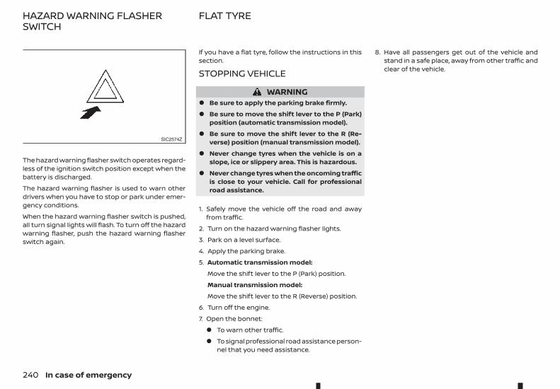
The hazard warning flasher switch operates regard-less of the ignition switch position except when thebattery is discharged.
The hazard warning flasher is used to warn otherdrivers when you have to stop or park under emer-gency conditions.
When the hazard warning flasher switch is pushed,all turn signal lights will flash. To turn off the hazardwarning flasher, push the hazard warning flasherswitch again.
If you have a flat tyre, follow the instructions in thissection.
STOPPING VEHICLE
WARNING• Be sure to apply the parking brake firmly.
• Be sure to move the shift lever to the P (Park)position (automatic transmission model).
• Be sure to move the shift lever to the R (Re-verse) position (manual transmission model).
• Never change tyres when the vehicle is on aslope, ice or slippery area. This is hazardous.
• Never change tyres when the oncoming trafficis close to your vehicle. Call for professionalroad assistance.
1. Safely move the vehicle off the road and awayfrom traffic.
2. Turn on the hazard warning flasher lights.
3. Park on a level surface.
4. Apply the parking brake.
5. Automatic transmission model:
Move the shift lever to the P (Park) position.
Manual transmission model:
Move the shift lever to the R (Reverse) position.
6. Turn off the engine.
7. Open the bonnet:
• To warn other traffic.
• To signal professional road assistance person-nel that you need assistance.
8. Have all passengers get out of the vehicle andstand in a safe place, away from other traffic andclear of the vehicle.
SIC2574Z
HAZARD WARNING FLASHERSWITCH
FLAT TYRE
240 In case of emergency
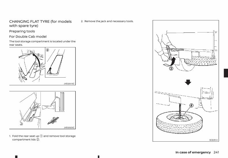
CHANGING FLAT TYRE (for modelswith spare tyre)Preparing toolsFor Double Cab modelThe tool storage compartment is located under therear seats.
1. Fold the rear seat up ➀ and remove tool storagecompartment lids ➁.
2. Remove the jack and necessary tools.
JVE0201XZ
JVE0202XZ
SCE0514
In case of emergency 241
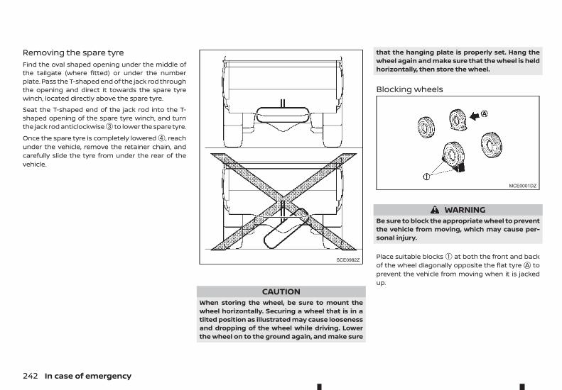
Removing the spare tyreFind the oval shaped opening under the middle ofthe tailgate (where fitted) or under the numberplate. Pass the T-shaped end of the jack rod throughthe opening and direct it towards the spare tyrewinch, located directly above the spare tyre.
Seat the T-shaped end of the jack rod into the T-shaped opening of the spare tyre winch, and turnthe jack rod anticlockwise ➂ to lower the spare tyre.
Once the spare tyre is completely lowered ➃, reachunder the vehicle, remove the retainer chain, andcarefully slide the tyre from under the rear of thevehicle.
CAUTIONWhen storing the wheel, be sure to mount thewheel horizontally. Securing a wheel that is in atilted position as illustrated may cause loosenessand dropping of the wheel while driving. Lowerthe wheel on to the ground again, and make sure
that the hanging plate is properly set. Hang thewheel again and make sure that the wheel is heldhorizontally, then store the wheel.
Blocking wheels
WARNINGBe sure to block the appropriate wheel to preventthe vehicle from moving, which may cause per-sonal injury.
Place suitable blocks ➀ at both the front and backof the wheel diagonally opposite the flat tyrejA toprevent the vehicle from moving when it is jackedup.
SCE0982Z
MCE0001DZ
242 In case of emergency
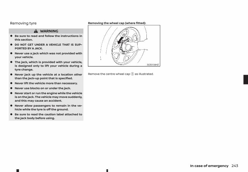
Removing tyre
WARNING• Be sure to read and follow the instructions in
this section.
• DO NOT GET UNDER A VEHICLE THAT IS SUP-PORTED BY A JACK.
• Never use a jack which was not provided withyour vehicle.
• The jack, which is provided with your vehicle,is designed only to lift your vehicle during atyre change.
• Never jack up the vehicle at a location otherthan the jack-up point that is specified.
• Never lift the vehicle more than necessary.
• Never use blocks on or under the jack.
• Never start or run the engine while the vehicleis on the jack. The vehicle may move suddenly,and this may cause an accident.
• Never allow passengers to remain in the ve-hicle while the tyre is off the ground.
• Be sure to read the caution label attached tothe jack body before using.
Removing the wheel cap (where fitted):
Remove the centre wheel cap ➀ as illustrated.
SCE0139HZ
In case of emergency 243
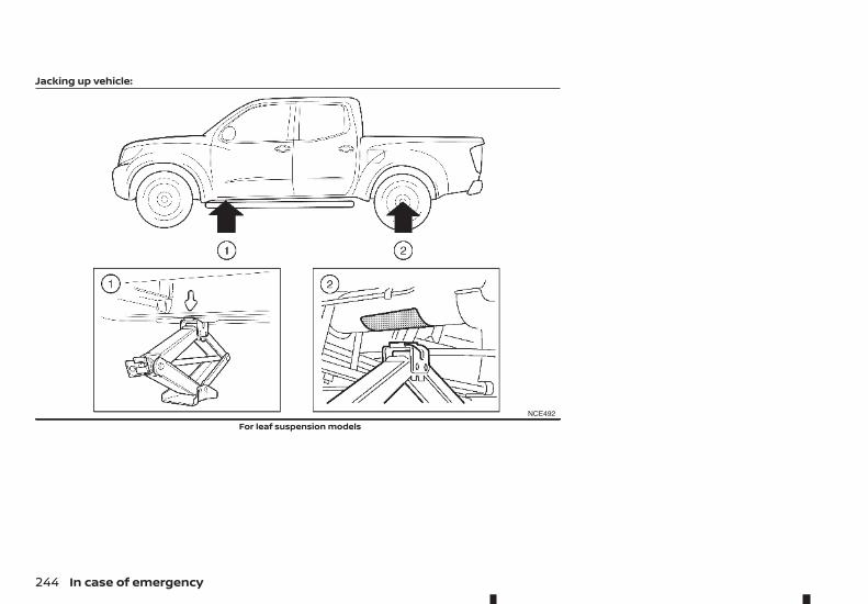
Jacking up vehicle:
NCE492
For leaf suspension models
244 In case of emergency
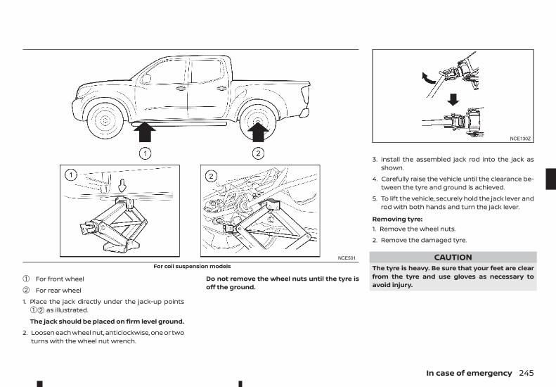
➀ For front wheel
➁ For rear wheel
1. Place the jack directly under the jack-up points➀➁ as illustrated.
The jack should be placed on firm level ground.
2. Loosen each wheel nut, anticlockwise, one or twoturns with the wheel nut wrench.
Do not remove the wheel nuts until the tyre isoff the ground.
3. Install the assembled jack rod into the jack asshown.
4. Carefully raise the vehicle until the clearance be-tween the tyre and ground is achieved.
5. To lift the vehicle, securely hold the jack lever androd with both hands and turn the jack lever.
Removing tyre:1. Remove the wheel nuts.
2. Remove the damaged tyre.
CAUTIONThe tyre is heavy. Be sure that your feet are clearfrom the tyre and use gloves as necessary toavoid injury.
NCE501
For coil suspension models
NCE130Z
In case of emergency 245
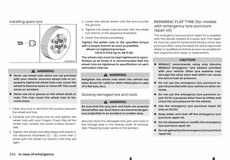
Installing spare tyre
WARNING• Never use wheel nuts which are not provided
with your vehicle. Incorrect wheel nuts or im-properly tightened wheel nuts may cause thewheel to become loose or come off. This couldcause an accident.
• Never use oil or grease on the wheel studs ornuts. This may cause the wheel nuts to be-come loose.
1. Clean any mud or dirt from the surface betweenthe wheel and hub.
2. Carefully put the spare tyre on and tighten thewheel nuts with your fingers. Check that all thewheel nuts contact the wheel surface horizon-tally.
3. Tighten the wheel nuts alternately and evenly inthe sequence illustrated (➀ - ➅), more than 2times with the wheel nut wrench, until they aretight.
4. Lower the vehicle slowly until the tyre touchesthe ground.
5. Tighten the wheel nuts securely, with the wheelnut wrench, in the sequence illustrated.
6. Lower the vehicle completely.
Tighten the wheel nuts to the specified torquewith a torque wrench as soon as possible.
Wheel nut tightening torque:133 N·m (13.6 kg-m, 98 ft-lb)
The wheel nuts must be kept tightened to speci-fication at all times. It is recommended that thewheel nuts be tightened to specification at eachlubrication interval.
WARNINGRetighten the wheel nuts when the vehicle hasbeen driven for 1,000 km (600 miles) (also in caseof a flat tyre, etc.).
Stowing damaged tyre and tools
WARNINGBe sure that the tyre, jack and tools are properlystored after use. Such items can become danger-ous projectiles in an accident or sudden stop.
Securely store the damaged tyre, jack and tools inthe storage area in the reverse order of removal.(See “Preparing tools” earlier in this section.)
REPAIRING FLAT TYRE (for modelswith emergency tyre puncturerepair kit)The emergency tyre puncture repair kit is suppliedwith the vehicle instead of a spare tyre. This repairkit must be used for temporarily fixing a minor tyrepuncture. After using the repair kit, see an approveddealer or qualified workshop as soon as possible fortyre inspection and repair or replacement.
CAUTION• RENAULT recommends using only Genuine
RENAULT Emergency Tyre Sealant providedwith your vehicle. Other tyre sealants maydamage the valve stem seal which can causethe tyre to lose air pressure.
• Do not use the emergency tyre puncture re-pair kit provided with your vehicle on other ve-hicles.
• Do not use the emergency tyre puncture re-pair kit for a purpose other than to inflate andcheck the tyre pressure for the vehicle.
• Use the emergency tyre puncture repair kitonly on DC12V.
• Keep water and dust off the emergency tyrepuncture repair kit.
• Do not disassemble or modify the emergencytyre puncture repair kit.
• Do not galvanise the emergency tyre puncturerepair kit.
JVE0208XZ
246 In case of emergency
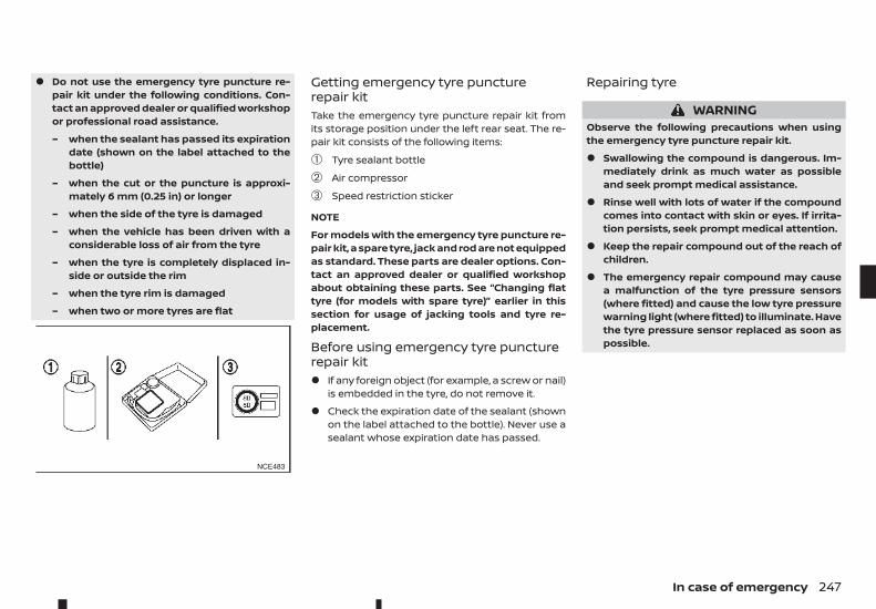
• Do not use the emergency tyre puncture re-pair kit under the following conditions. Con-tact an approved dealer or qualified workshopor professional road assistance.
– when the sealant has passed its expirationdate (shown on the label attached to thebottle)
– when the cut or the puncture is approxi-mately 6 mm (0.25 in) or longer
– when the side of the tyre is damaged
– when the vehicle has been driven with aconsiderable loss of air from the tyre
– when the tyre is completely displaced in-side or outside the rim
– when the tyre rim is damaged
– when two or more tyres are flat
Getting emergency tyre puncturerepair kitTake the emergency tyre puncture repair kit fromits storage position under the left rear seat. The re-pair kit consists of the following items:
➀ Tyre sealant bottle
➁ Air compressor
➂ Speed restriction sticker
NOTE
For models with the emergency tyre puncture re-pair kit, a spare tyre, jack and rod are not equippedas standard. These parts are dealer options. Con-tact an approved dealer or qualified workshopabout obtaining these parts. See “Changing flattyre (for models with spare tyre)” earlier in thissection for usage of jacking tools and tyre re-placement.
Before using emergency tyre puncturerepair kit• If any foreign object (for example, a screw or nail)
is embedded in the tyre, do not remove it.
• Check the expiration date of the sealant (shownon the label attached to the bottle). Never use asealant whose expiration date has passed.
Repairing tyre
WARNINGObserve the following precautions when usingthe emergency tyre puncture repair kit.
• Swallowing the compound is dangerous. Im-mediately drink as much water as possibleand seek prompt medical assistance.
• Rinse well with lots of water if the compoundcomes into contact with skin or eyes. If irrita-tion persists, seek prompt medical attention.
• Keep the repair compound out of the reach ofchildren.
• The emergency repair compound may causea malfunction of the tyre pressure sensors(where fitted) and cause the low tyre pressurewarning light (where fitted) to illuminate. Havethe tyre pressure sensor replaced as soon aspossible.
NCE483
In case of emergency 247
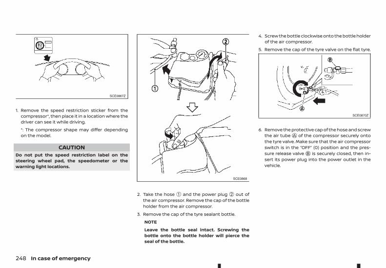
1. Remove the speed restriction sticker from thecompressor*, then place it in a location where thedriver can see it while driving.
*: The compressor shape may differ dependingon the model.
CAUTIONDo not put the speed restriction label on thesteering wheel pad, the speedometer or thewarning light locations.
2. Take the hose ➀ and the power plug ➁ out ofthe air compressor. Remove the cap of the bottleholder from the air compressor.
3. Remove the cap of the tyre sealant bottle.
NOTE
Leave the bottle seal intact. Screwing thebottle onto the bottle holder will pierce theseal of the bottle.
4. Screw the bottle clockwise onto the bottle holderof the air compressor.
5. Remove the cap of the tyre valve on the flat tyre.
6. Remove the protective cap of the hose and screwthe air tubejA of the compressor securely ontothe tyre valve. Make sure that the air compressorswitch is in the “OFF” (0) position and the pres-sure release valvejB is securely closed, then in-sert its power plug into the power outlet in thevehicle.
SCE0867Z
SCE0868
SCE0870Z
248 In case of emergency
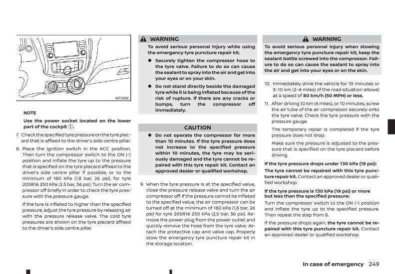
NOTE
Use the power socket located on the lowerpart of the cockpit ➀.
7. Check the specified tyre pressure on the tyre plac-ard that is affixed to the driver’s side centre pillar.
8. Place the ignition switch in the ACC position.Then turn the compressor switch to the ON (−)position and inflate the tyre up to the pressurethat is specified on the tyre placard affixed to thedriver’s side centre pillar if possible, or to theminimum of 180 kPa (1.8 bar, 26 psi), for tyre205R16 250 kPa (2.5 bar, 36 psi). Turn the air com-pressor off briefly in order to check the tyre pres-sure with the pressure gauge.
If the tyre is inflated to higher than the specifiedpressure, adjust the tyre pressure by releasing airwith the pressure release valve. The cold tyrepressures are shown on the tyre placard affixedto the driver’s side centre pillar.
WARNINGTo avoid serious personal injury while usingthe emergency tyre puncture repair kit.
• Securely tighten the compressor hose tothe tyre valve. Failure to do so can causethe sealant to spray into the air and get intoyour eyes or on your skin.
• Do not stand directly beside the damagedtyre while it is being inflated because of therisk of rupture. If there are any cracks orbumps, turn the compressor offimmediately.
CAUTION• Do not operate the compressor for more
than 10 minutes. If the tyre pressure doesnot increase to the specified pressurewithin 10 minutes, the tyre may be seri-ously damaged and the tyre cannot be re-paired with this tyre repair kit. Contact anapproved dealer or qualified workshop.
9. When the tyre pressure is at the specified value,close the pressure release valve and turn the aircompressor off. If the pressure cannot be inflatedto the specified value, the air compressor can beturned off at the minimum of 180 kPa (1,8 bar, 26psi) for tyre 205R16 250 kPa (2,5 bar, 36 psi). Re-move the power plug from the power outlet andquickly remove the hose from the tyre valve. At-tach the protective cap and valve cap. Properlystow the emergency tyre puncture repair kit inthe storage location.
WARNINGTo avoid serious personal injury when stowingthe emergency tyre puncture repair kit, keep thesealant bottle screwed into the compressor. Fail-ure to do so can cause the sealant to spray intothe air and get into your eyes or on the skin.
10. Immediately drive the vehicle for 10 minutes or3–10 km (2–6 miles) (if the road situation allows)at a speed of 80 km/h (50 MPH) or less.
11. After driving 10 km (6 miles), or 10 minutes, screwthe air tube of the air compressor securely ontothe tyre valve. Check the tyre pressure with thepressure gauge.
The temporary repair is completed if the tyrepressure does not drop.
Make sure the pressure is adjusted to the pres-sure that is specified on the tyre placard beforedriving.
If the tyre pressure drops under 130 kPa (19 psi):The tyre cannot be repaired with this tyre punc-ture repair kit. Contact an approved dealer or quali-fied workshop.
If the tyre pressure is 130 kPa (19 psi) or morebut less than the specified pressure:Turn the compressor switch to the ON (−) positionand inflate the tyre up to the specified pressure.Then repeat the step from 8.
If the pressure drops again, the tyre cannot be re-paired with this tyre puncture repair kit. Contactan approved dealer or qualified workshop.
NIC3668
In case of emergency 249
When the tyre pressure is the specified pressure:The temporary repair is completed.
See an approved dealer or qualified workshop forthe repair/replacement as soon as possible.
After repairing tyreSee an approved dealer or qualified workshop fortyre repair or replacement and for a new tyre seal-ant bottle and hose, as soon as possible.
CAUTION• Before driving, ensure tyre is adjusted to rec-
ommended inflation pressure as indicated onvehicle placard. Monitor tyre pressure untilsealed tyre is replaced.
• Do not drive the vehicle at speeds faster than50 MPH (80 km/h), and the damaged tyre mustbe replaced as quickly as possible (within amaximum driving distance of 200 km (120miles)). You must not continue to drive if heavyvibrations, unsteady steering behaviour ornoises should occur while driving.
• Immediately after using Emergency Tyre Seal-ant to repair a minor tyre puncture, take yourvehicle to an approved dealer or qualifiedworkshop to inspect, and repair or replace thetyre. The Emergency Tyre Sealant cannot per-manently seal a punctured tyre. Continuingoperation of the vehicle without a permanenttyre repair can lead to a crash.
• RENAULT recommends using only RENAULTGenuine Emergency Tyre Sealant providedwith your vehicle. Other tyre sealants maydamage the valve stem seal which can causethe tyre to lose air pressure.
WARNING• Incorrect jump starting can lead to a battery
explosion. The battery explosion may result insevere injury or death. It may also result indamage to the vehicle. Be sure to follow theinstructions in this section.
• Explosive hydrogen gas is always present inthe vicinity of the battery. Keep all sparks andflames away from the battery.
• Always wear suitable eye protection and re-move rings, bracelets, and any other jewellerywhenever working on or near a battery.
• Never lean over the battery while jump start-ing.
• Never allow battery fluid to come into contactwith eyes, skin, clothes or the vehicle’s paintedsurfaces. Battery fluid is a corrosive sulphuricacid which can cause severe burns. If the fluidcomes into contact with anything, immedi-ately flush the contacted area with plenty ofwater.
• Keep the battery out of the reach of children.
• The booster battery must be rated at 12 volts.Use of an incorrectly rated battery will dam-age your vehicle.
• Never attempt to jump start a frozen battery.It could explode and cause serious injury.
JUMP STARTING
250 In case of emergency

In case of emergency 251
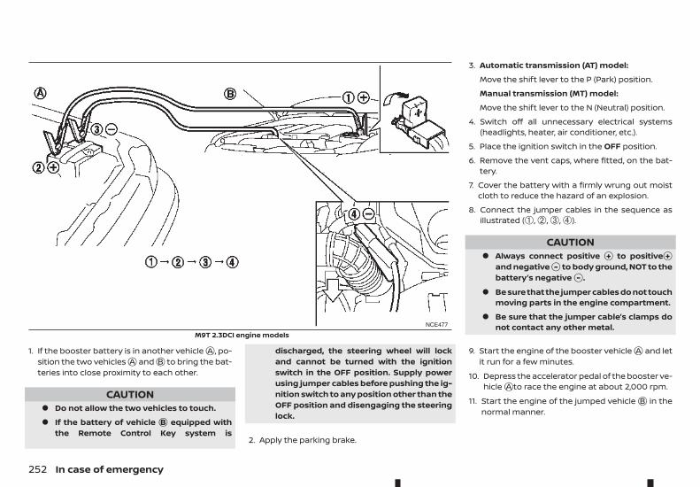
1. If the booster battery is in another vehiclejA , po-sition the two vehiclesjA andjB to bring the bat-teries into close proximity to each other.
CAUTION• Do not allow the two vehicles to touch.
• If the battery of vehicle jB equipped withthe Remote Control Key system is
discharged, the steering wheel will lockand cannot be turned with the ignitionswitch in the OFF position. Supply powerusing jumper cables before pushing the ig-nition switch to any position other than theOFF position and disengaging the steeringlock.
2. Apply the parking brake.
3. Automatic transmission (AT) model:
Move the shift lever to the P (Park) position.
Manual transmission (MT) model:
Move the shift lever to the N (Neutral) position.
4. Switch off all unnecessary electrical systems(headlights, heater, air conditioner, etc.).
5. Place the ignition switch in the OFF position.
6. Remove the vent caps, where fitted, on the bat-tery.
7. Cover the battery with a firmly wrung out moistcloth to reduce the hazard of an explosion.
8. Connect the jumper cables in the sequence asillustrated (➀, ➁, ➂, ➃).
CAUTION• Always connect positive j+ to positivej+
and negativej- to body ground, NOT to thebattery’s negativej- .
• Be sure that the jumper cables do not touchmoving parts in the engine compartment.
• Be sure that the jumper cable’s clamps donot contact any other metal.
9. Start the engine of the booster vehiclejA and letit run for a few minutes.
10. Depress the accelerator pedal of the booster ve-hiclejA to race the engine at about 2,000 rpm.
11. Start the engine of the jumped vehiclejB in thenormal manner.
NCE477
M9T 2.3DCI engine models
252 In case of emergency
CAUTIONNever keep the starter motor engaged formore than 10 seconds. If the engine does notstart right away, place the ignition switch inthe “LOCK” position and wait at least 10 sec-onds before trying again.
12. After the engine is started, carefully disconnectthe jumper cables in the opposite sequencefrom that illustrated (➃, ➂, ➁, ➀).
13. Remove and dispose of the cloth properly as itmay be contaminated with corrosive acid.
14. Replace the vent caps, if removed.
Do not attempt to start the engine by pushing thevehicle.
CAUTION• Automatic Transmission (AT) model cannot be
started by pushing. Attempting to do so maycause damage to the transmission.
• Three-way catalyst equipped model shouldnot be started by pushing. Attempting to doso may cause damage to the three-way cata-lyst.
• Diesel Oxidation Catalyst equipped modelshould not be started by pushing. Attemptingto do so may cause damage to the catalyst.
• Never try to start the engine by towing. Whenthe engine starts, the forward surge couldcause the vehicle to collide with the towingvehicle.
WARNING• Never continue driving if your vehicle over-
heats. Doing so could cause engine damageand/or a vehicle fire.
• Never open the bonnet if steam is coming out.
• Never remove the radiator or coolant reservoircap while the engine is hot. If the radiator orcoolant reservoir cap is removed when the en-gine is hot, pressurised hot water will spurt outand possibly cause burning, scalding or seri-ous injury.
• If steam or coolant is coming from the engine,stand clear of the vehicle to prevent gettingscalded.
• The engine cooling fan can start at any timewhen the coolant temperature exceeds presetdegrees.
• Be careful not to allow your hands, hair, jewel-lery or clothing to come into contact with, orto get caught in the cooling fan or drive belts.
If your vehicle is overheating, or if you feel a lack ofengine power, detect unusual noise, etc., take thefollowing steps:
1. Safely move the vehicle off the road away fromtraffic.
2. Turn on the hazard indicator flashers.
3. Apply the parking brake.
PUSH STARTING IF YOUR VEHICLE OVERHEATS
In case of emergency 253
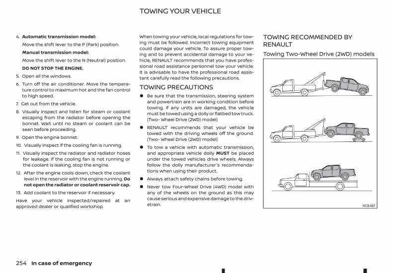
4. Automatic transmission model:
Move the shift lever to the P (Park) position.
Manual transmission model:
Move the shift lever to the N (Neutral) position.
DO NOT STOP THE ENGINE.
5. Open all the windows.
6. Turn off the air conditioner. Move the tempera-ture control to maximum hot and the fan controlto high speed.
7. Get out from the vehicle.
8. Visually inspect and listen for steam or coolantescaping from the radiator before opening thebonnet. Wait until no steam or coolant can beseen before proceeding.
9. Open the engine bonnet.
10. Visually inspect if the cooling fan is running.
11. Visually inspect the radiator and radiator hosesfor leakage. If the cooling fan is not running orthe coolant is leaking, stop the engine.
12. After the engine cools down, check the coolantlevel in the reservoir with the engine running. Donot open the radiator or coolant reservoir cap.
13. Add coolant to the reservoir if necessary.
Have your vehicle inspected/repaired at anapproved dealer or qualified workshop.
When towing your vehicle, local regulations for tow-ing must be followed. Incorrect towing equipmentcould damage your vehicle. To assure proper tow-ing and to prevent accidental damage to your ve-hicle, RENAULT recommends that you have profes-sional road assistance personnel tow your vehicle.It is advisable to have the professional road assis-tant carefully read the following precautions.
TOWING PRECAUTIONS• Be sure that the transmission, steering system
and powertrain are in working condition beforetowing. If any units are damaged, the vehiclemust be towed using a dolly or flatbed tow truck.(Two- Wheel Drive (2WD) model)
• RENAULT recommends that your vehicle betowed with the driving wheels off the ground.(Two- Wheel Drive (2WD) model)
• To tow a vehicle with automatic transmission,and appropriate vehicle dolly MUST be placedunder the towed vehicles drive wheels. Alwaysfollow the dolly manufacturer's recommenda-tions when using their product.
• Always attach safety chains before towing.
• Never tow Four-Wheel Drive (4WD) model withany of the wheels on the ground as this maycause serious and expensive damage to the driv-etrain.
TOWING RECOMMENDED BYRENAULTTowing Two-Wheel Drive (2WD) models
NCE482
TOWING YOUR VEHICLE
254 In case of emergency
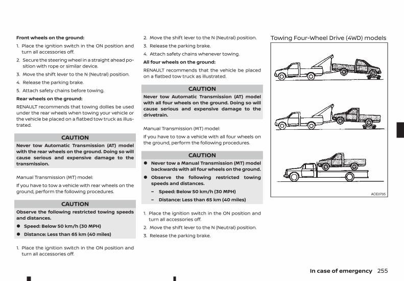
Front wheels on the ground:
1. Place the ignition switch in the ON position andturn all accessories off.
2. Secure the steering wheel in a straight ahead po-sition with rope or similar device.
3. Move the shift lever to the N (Neutral) position.
4. Release the parking brake.
5. Attach safety chains before towing.
Rear wheels on the ground:
RENAULT recommends that towing dollies be usedunder the rear wheels when towing your vehicle orthe vehicle be placed on a flatbed tow truck as illus-trated.
CAUTIONNever tow Automatic Transmission (AT) modelwith the rear wheels on the ground. Doing so willcause serious and expensive damage to thetransmission.
Manual Transmission (MT) model:
If you have to tow a vehicle with rear wheels on theground, perform the following procedures.
CAUTIONObserve the following restricted towing speedsand distances.
• Speed: Below 50 km/h (30 MPH)
• Distance: Less than 65 km (40 miles)
1. Place the ignition switch in the ON position andturn all accessories off.
2. Move the shift lever to the N (Neutral) position.
3. Release the parking brake.
4. Attach safety chains whenever towing.
All four wheels on the ground:
RENAULT recommends that the vehicle be placedon a flatbed tow truck as illustrated.
CAUTIONNever tow Automatic Transmission (AT) modelwith all four wheels on the ground. Doing so willcause serious and expensive damage to thedrivetrain.
Manual Transmission (MT) model:
If you have to tow a vehicle with all four wheels onthe ground, perform the following procedures.
CAUTION• Never tow a Manual Transmission (MT) model
backwards with all four wheels on the ground.
• Observe the following restricted towingspeeds and distances.
– Speed: Below 50 km/h (30 MPH)
– Distance: Less than 65 km (40 miles)
1. Place the ignition switch in the ON position andturn all accessories off.
2. Move the shift lever to the N (Neutral) position.
3. Release the parking brake.
Towing Four-Wheel Drive (4WD) models
ACE0705
In case of emergency 255
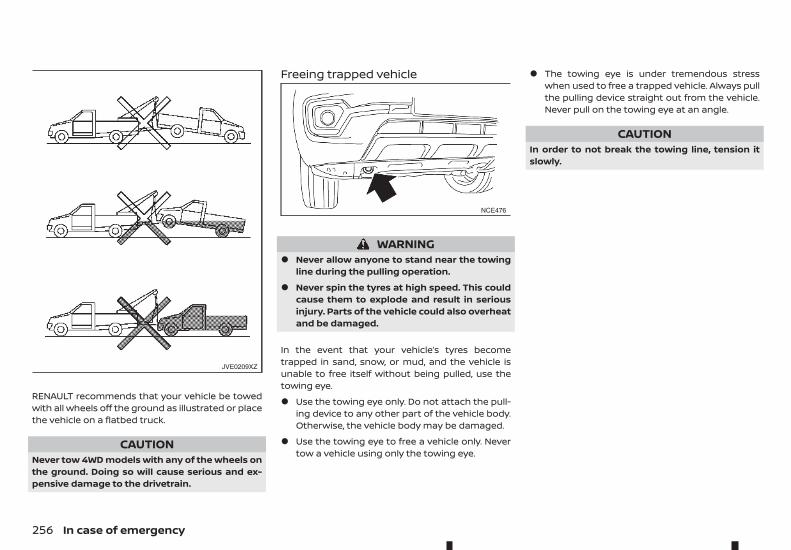
RENAULT recommends that your vehicle be towedwith all wheels off the ground as illustrated or placethe vehicle on a flatbed truck.
CAUTIONNever tow 4WD models with any of the wheels onthe ground. Doing so will cause serious and ex-pensive damage to the drivetrain.
Freeing trapped vehicle
WARNING• Never allow anyone to stand near the towing
line during the pulling operation.
• Never spin the tyres at high speed. This couldcause them to explode and result in seriousinjury. Parts of the vehicle could also overheatand be damaged.
In the event that your vehicle’s tyres becometrapped in sand, snow, or mud, and the vehicle isunable to free itself without being pulled, use thetowing eye.
• Use the towing eye only. Do not attach the pull-ing device to any other part of the vehicle body.Otherwise, the vehicle body may be damaged.
• Use the towing eye to free a vehicle only. Nevertow a vehicle using only the towing eye.
• The towing eye is under tremendous stresswhen used to free a trapped vehicle. Always pullthe pulling device straight out from the vehicle.Never pull on the towing eye at an angle.
CAUTIONIn order to not break the towing line, tension itslowly.
JVE0209XZ
NCE476
256 In case of emergency
7 Appearance and careAppearance and care
Cleaning exterior.......................................................................................... 258Washing....................................................................................................... 258Removing spots.................................................................................... 258Waxing.......................................................................................................... 259Glass .............................................................................................................. 259Underbody................................................................................................ 259Wheels .......................................................................................................... 259Aluminium alloy wheels .................................................................. 259Side step boards................................................................................... 259Chrome parts.......................................................................................... 259
Cleaning interior........................................................................................... 260
Air fresheners.......................................................................................... 260Floor mats ................................................................................................. 260Glass .............................................................................................................. 260Seat belts ................................................................................................... 261
Corrosion protection................................................................................. 261Most common factors contributing to vehiclecorrosion .................................................................................................... 261Environmental factors influence the rate ofcorrosion .................................................................................................... 261To protect your vehicle from corrosion .............................. 261
In order to maintain the appearance of your vehicle,it is important to take proper care of it.
Whenever possible, park your vehicle inside a ga-rage or in a covered area to minimise the chancesof damaging the paint surface of your vehicle.
When it is necessary to park outside, park in a shadyarea or protect the vehicle with a body cover. Becareful not to scratch the paint surface when put-ting on or removing the body cover.
WASHINGIn the following instances, wash your vehicle assoon as possible to protect the paint surface:
• After a rainfall, which may cause the paint sur-face damage from acid rain.
• After driving on coastal roads, which may causerusting from the sea breeze.
• When contaminants such as soot, birddroppings, tree sap, metal particles or bugs geton the paint surface.
• When dust or mud builds up on the paint sur-face.
1. Wash the vehicle surface with a wet sponge andplenty of water.
2. Clean the vehicle surface gently and thoroughlyusing a mild soap, a special vehicle soap or a gen-eral purpose dishwashing liquid mixed withclean, lukewarm (never hot) water.
CAUTION• Do not wash the vehicle with strong house-
hold soap, strong chemical detergents,petrol or solvents.
• Do not wash the vehicle in direct sunlightor while the vehicle body is hot, as the paintsurface may become water-spotted.
• Avoid using tight-napped or rough cloths,such as washing mitts. Care must be takenwhen removing caked-on dirt or other for-eign substances so the paint surface is notscratched or damaged.
• Lock all doors before going through auto-matic car wash. Locking doors helps pre-vent fuel filler lid from opening and becom-ing damaged.
3. Rinse the vehicle thoroughly with plenty of cleanwater.
4. Use a dampened chamois to dry the paint sur-face and avoid leaving water spots.
When washing the vehicle, take care of the follow-ing:
• Inside flanges, joints and folds on the doors,hatches and bonnet are particularly vulnerableto the effects of road salt. Therefore, these areasmust be cleaned regularly.
• Be sure that the drain holes in the lower edge ofthe doors are not clogged.
• Spray water on the underbody and in the wheelwells to loosen the dirt and/or wash away roadsalt.
STICKERS, BADGES, STRIPES ORGRAPHICS (where fitted)To maintain the premium anodized finish of person-alised stickers, stripes and graphics on your vehicle,please observe the following care points:
• Only hand wash the surface, using PH neutraldetergents.
• Do not use an automated car wash.
• Do not use chemical agents (abrasive products,polishes, petrol, wax, protective products, corro-sive solvents, etc).
• Wash your vehicle as soon as you can if any in-sects, bird droppings, soot or metallic particlesappear on the paint surface.
• The anodized finish may deteriorate if itstouched by bare hands or marked by road oil(tar, etc.). Wash any dirt off the vehicle with a wetmicrofibre cloth and plenty of clean water.
• Avoid parking your vehicle under trees and re-move any tree sap as soon as possible.
• Gently wash stickers using a clean sponge. Donot use a pressure washer.
REMOVING SPOTSRemove tar and oil spots, industrial dust, insects,and tree sap as quickly as possible from the paintsurface to avoid lasting damage or staining. Specialcleaning products are available at an approveddealer or any automotive accessory store.
CLEANING EXTERIOR
258 Appearance and care
WAXINGRegular waxing protects the paint surface and helpsmaintain a new vehicle appearance.
After waxing, polishing is recommended to removebuilt-up residue and to avoid a weathered appear-ance.
An approved dealer can assist you in choosing theappropriate waxing products.
CAUTION• Wash your vehicle thoroughly and completely
before applying wax to the paint surface.
• Always follow the manufacturer’s instructionssupplied with the wax.
• Do not use a wax containing any abrasives,cutting compounds or cleaners that maydamage the vehicle finish.
Machine compounding or aggressive polishing on abase coat/clear coat paint finish may dull the finishor leave swirl marks.
GLASSUse glass cleaner to remove smoke and dust filmfrom the glass surfaces. It is normal for glass to be-come coated with a film after the vehicle is parkedin the hot sun. Glass cleaner and a soft cloth willeasily remove this film.
UNDERBODYIn areas where road salt is used in the winter, it isnecessary to clean the vehicle’s underbody regu-larly in order to prevent dirt and salt from buildingup and causing the acceleration of corrosion on theunderbody and suspension.
Before the winter and again in the spring, the under-seal must be checked and, if necessary, re-treated.
WHEELS• Wash the wheels when washing the vehicle to
maintain their appearance.
• Clean the inner side of the wheels when thewheel is changed or the underside of the vehicleis washed.
• Do not use abrasive cleaners when washing thewheels.
• Inspect wheel rims regularly for dents or corro-sion. This may cause loss of pressure or damagethe tyre bead.
• RENAULT recommends that the road wheels bewaxed to protect against road salt in areaswhere it is used during winter.
ALUMINIUM ALLOY WHEELSWash the wheels regularly with a sponge dampenedin a mild soap solution, especially during winter inareas where road salt is used. The salt residue fromroad salt could discolour the wheels if it is notwashed off regularly.
CAUTIONFollow the directions below to avoid staining ordiscolouring the wheels:
• Do not use a cleaner that uses strong acid oralkali contents to clean the wheels.
• Do not apply wheel cleaners to the wheelswhen they are hot. The wheel temperatureshould be the same as ambient temperature.
• Rinse the wheel to completely remove thecleaner within 15 minutes after the cleaner isapplied.
SIDE STEP BOARDS
CAUTIONWhen cleaning the side step boards, follow theinstruction below:
• Do not use a cleaner that uses strong acid oralkali contents to clean the side step boards.Using strong acid or alkali contents may dam-age the side step board surface.
• Rinse the side step boards to completely re-move the cleaner within 15 minutes after thecleaner is applied.
CHROME PARTSClean all chrome parts regularly with a non abrasivechrome polish to maintain the finish.
Appearance and care 259
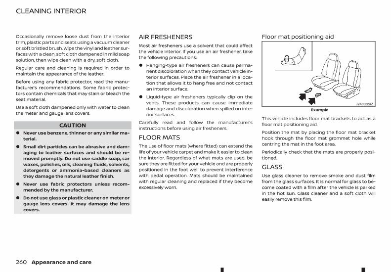
Occasionally remove loose dust from the interiortrim, plastic parts and seats using a vacuum cleaneror soft bristled brush. Wipe the vinyl and leather sur-faces with a clean, soft cloth dampened in mild soapsolution, then wipe clean with a dry, soft cloth.
Regular care and cleaning is required in order tomaintain the appearance of the leather.
Before using any fabric protector, read the manu-facturer’s recommendations. Some fabric protec-tors contain chemicals that may stain or bleach theseat material.
Use a soft cloth dampened only with water to cleanthe meter and gauge lens covers.
CAUTION• Never use benzene, thinner or any similar ma-
terial.
• Small dirt particles can be abrasive and dam-aging to leather surfaces and should be re-moved promptly. Do not use saddle soap, carwaxes, polishes, oils, cleaning fluids, solvents,detergents or ammonia-based cleaners asthey damage the natural leather finish.
• Never use fabric protectors unless recom-mended by the manufacturer.
• Do not use glass or plastic cleaner on meter orgauge lens covers. It may damage the lenscovers.
AIR FRESHENERSMost air fresheners use a solvent that could affectthe vehicle interior. If you use an air freshener, takethe following precautions:
• Hanging-type air fresheners can cause perma-nent discoloration when they contact vehicle in-terior surfaces. Place the air freshener in a loca-tion that allows it to hang free and not contactan interior surface.
• Liquid-type air fresheners typically clip on thevents. These products can cause immediatedamage and discoloration when spilled on inte-rior surfaces.
Carefully read and follow the manufacturer’sinstructions before using air fresheners.
FLOOR MATSThe use of floor mats (where fitted) can extend thelife of your vehicle carpet and make it easier to cleanthe interior. Regardless of what mats are used, besure they are fitted for your vehicle and are properlypositioned in the foot well to prevent interferencewith pedal operation. Mats should be maintainedwith regular cleaning and replaced if they becomeexcessively worn.
Floor mat positioning aid
This vehicle includes floor mat brackets to act as afloor mat positioning aid.
Position the mat by placing the floor mat brackethook through the floor mat grommet hole whilecentring the mat in the foot area.
Periodically check that the mats are properly posi-tioned.
GLASSUse glass cleaner to remove smoke and dust filmfrom the glass surfaces. It is normal for glass to be-come coated with a film after the vehicle is parkedin the hot sun. Glass cleaner and a soft cloth willeasily remove this film.
JVA0022XZ
Example
CLEANING INTERIOR
260 Appearance and care
CAUTIONWhen cleaning the inside of the windows, do notuse sharp-edged tools, abrasive cleaners or chlo-rine-based disinfectant cleaners. They coulddamage the electrical conductors, such as radioantenna elements or rear window defoggerelements.
SEAT BELTS
WARNING• Do not allow wet seat belts to roll up in the
retractor.
• Never use bleach, dye or chemical solvents toclean the seat belts, since these materials mayseverely weaken the seat belt webbing.
The seat belts can be cleaned by wiping them witha sponge dampened in a mild soap solution.
Allow the belts to dry completely in the shade be-fore using them. (See “Seat belts” in the “1. Safety —seats, seat belts and supplemental restraint system”section.)
MOST COMMON FACTORSCONTRIBUTING TO VEHICLECORROSION• The accumulation of moisture-retaining dirt and
debris in body panel sections, cavities, and otherareas.
• Damage to the paint surface and other protec-tive coatings caused by gravel and stone chipsor minor traffic accidents.
ENVIRONMENTAL FACTORSINFLUENCE THE RATE OFCORROSIONMoistureThe accumulation of sand, dirt and water on theinside floor of the vehicle can accelerate corrosion.Wet floor carpet/floor mats will not dry completelyinside the vehicle. They should be removed andcompletely dried to avoid floor panel corrosion.
Relative humidityCorrosion will be accelerated in areas of high rela-tive humidity.
TemperatureHigh temperatures accelerate the rate of corrosionto those parts which are not well ventilated.
Corrosion will also be accelerated in areas wherethe temperatures stay above freezing.
Air pollutionIndustrial pollution, the presence of salt in the air incoastal areas, or heavy road salt use accelerates thecorrosion process. Road salt also accelerates thedisintegration of paint surfaces.
TO PROTECT YOUR VEHICLE FROMCORROSION• Wash and wax your vehicle often to keep the
vehicle clean.
• Always check for minor damage to the paint sur-face and if any exists, repair it as soon as pos-sible.
• Keep the drain holes in the lower edge of thedoors open to avoid water accumulation.
• Check the vehicle underbody for accumulationof sand, dirt or salt. If present, wash with wateras soon as possible.
CAUTION• Never remove dirt, sand or other debris from
the passenger compartment by washing it outwith a hose. Remove dirt with a vacuumcleaner.
• Never allow water or other liquids to come incontact with electronic components inside thevehicle as this may damage them.
Chemicals used for road surface de-icing are ex-tremely corrosive. They accelerate corrosion anddeterioration of underbody components such asthe exhaust system, fuel and brake lines, brakecables, floor pan and wings.
CORROSION PROTECTION
Appearance and care 261
In the winter, the underbody must be cleaned pe-riodically.
For additional protection against rust and corro-sion, which may be required in some areas, consultan approved dealer or qualified workshop.
262 Appearance and care
8 Maintenance and do-it-yourselfMaintenance and do-it-yourself
Maintenance requirements.................................................................. 264Scheduled maintenance................................................................ 264General maintenance....................................................................... 264Where to go for service ................................................................... 264
General maintenance ............................................................................... 264Explanation of general maintenance items .................... 264Maintenance precautions ............................................................. 266
Engine compartment check locations........................................ 267Engine cooling system............................................................................. 267
Checking engine coolant level................................................... 268Changing engine coolant.............................................................. 268
Engine oil............................................................................................................ 268Checking engine oil level ............................................................... 268Changing engine oil and oil filter............................................. 269Protect environment......................................................................... 269
AdBlue® tank (where fitted for diesel enginemodel)................................................................................................................... 269
Refilling the AdBlue® tank ............................................................. 269Drive belt............................................................................................................. 270Automatic Transmission Fluid (ATF) (where fitted) ............ 270
7-speed Automatic Transmission (AT) model................. 270Power steering fluid................................................................................... 271Brakes................................................................................................................... 271
Checking parking brake ................................................................. 271Checking footbrake ........................................................................... 271Brake booster ......................................................................................... 272
Brake fluid.......................................................................................................... 272Clutch fluid (where fitted) ...................................................................... 273
Window washer fluid................................................................................. 274Battery ................................................................................................................. 275
Vehicle battery....................................................................................... 275Remote controller/Intelligent Key battery(where fitted)........................................................................................... 276
Air cleaner filter ............................................................................................. 279Wiper blades .................................................................................................... 279
Windscreen wiper blades............................................................... 279Variable voltage control system (where fitted)..................... 281Fuses ..................................................................................................................... 281
Engine compartment ....................................................................... 281Passenger compartment .............................................................. 282
Lights..................................................................................................................... 284Headlights ................................................................................................. 284Exterior lights.......................................................................................... 285Interior lights........................................................................................... 285Light locations ....................................................................................... 286
Tyres and wheels ......................................................................................... 290Tyre inflation pressure ..................................................................... 290Types of tyres.......................................................................................... 290Tyre chains................................................................................................ 291Tyre rotation............................................................................................ 291Tyre wear and damage ................................................................... 291Tyre age....................................................................................................... 292Changing tyres and wheels ......................................................... 292Wheel balance ........................................................................................ 292Spare tyre................................................................................................... 292
Some day-to-day and regular maintenance is es-sential to maintain your vehicle's good mechanicalcondition, as well as its emission and engine perfor-mance.
It is the owner’s responsibility to make sure that thespecified maintenance, as well as general mainte-nance, is performed.
As the vehicle owner, you are the only one who canensure that your vehicle receives the proper main-tenance care.
SCHEDULED MAINTENANCEFor your convenience, the required scheduled main-tenance items are described and listed in a sepa-rate Warranty Information and Maintenance book-let. You must refer to that booklet to ensure thatnecessary maintenance is performed on your ve-hicle at regular intervals.
GENERAL MAINTENANCEGeneral maintenance includes those items whichshould be checked during normal day-to-day op-eration of the vehicle. They are essential if your ve-hicle is to continue to operate properly. It is yourresponsibility to perform these procedures regu-larly as prescribed.
Performing general maintenance checks requiresminimal mechanical skill and only a few general au-tomotive tools.
These checks or inspections can be done by your-self, a qualified technician, or if you prefer, your ap-proved dealer or qualified workshop.
WHERE TO GO FOR SERVICEIf maintenance service is required or your vehicleappears to malfunction, have the systems checkedand tuned by an authorised approved dealer orqualified workshop.
During normal day-to-day operation of the vehicle,general maintenance should be performed regu-larly as prescribed in this section. If you detect anyunusual sounds, vibrations or smells, be sure tocheck for the cause or have an approved dealer orqualified workshop do it promptly. In addition, youshould notify an approved dealer or qualified work-shop if you think that repairs are required.
When performing any checks or maintenance work,closely observe “Maintenance precautions” later inthis section.
EXPLANATION OF GENERALMAINTENANCE ITEMSAdditional information on the following itemswith “*” is found later in this section.
Outside vehicleThe maintenance items listed here should be per-formed from time to time, unless otherwise speci-fied.
Doors and bonnet:Check that all doors and the bonnet operatesmoothly as well as the tailgate. Also make sure thatall latches lock securely. Lubricate if necessary. Makesure that the secondary latch keeps the bonnetfrom opening when the primary latch is released.When driving in areas using road salt or other cor-rosive materials, check lubrication frequently.
MAINTENANCE REQUIREMENTS GENERAL MAINTENANCE
264 Maintenance and do-it-yourself
Lights*:Clean the headlights on a regular basis. Make surethat the headlights, brake lights, tail lights, turn sig-nal lights, and other lights are all operating properlyand installed securely. Also check the aim of theheadlights.
Tyres*:Check the pressure with a gauge often and alwaysprior to long distance trips. Adjust the pressure in alltyres, including the spare, to the pressure specified.Check carefully for damage, cuts or excessive wear.
Tyre rotation*:In the case of Two-Wheel Drive (2WD), and wherefront and rear tyres are the same size: tyres shouldbe rotated every 10,000 km (6,000 miles). Tyresmarked with directional indicators can only be ro-tated between front and rear. Make sure that thedirectional indicators point in the direction of wheelrotation after the tyre rotation is completed.
In the case of the Four-Wheel Drive and All WheelDrive (4WD/AWD), and where front and rear tyresare the same size: tyres should be rotated every5,000 km (3,000 miles). Tyres marked with direc-tional indicators can only be rotated between frontand rear. Make sure that the directional indicatorspoint in the direction of wheel rotation after the tyrerotation is completed.
In the case that front tyres are different size fromrear tyres: tyres cannot be rotated.
The timing for tyre rotation may vary according toyour driving habits and the road surface conditions.
Wheel alignment and balance:If the vehicle should pull to either side while drivingon a straight and level road, or if you detect unevenor abnormal tyre wear, there may be a need forwheel alignment. If the steering wheel or seat vi-brates at normal highway speeds, wheel balancingmay be needed.
Windscreen:Clean the windscreen on a regular basis. Check thewindscreen at least every six months for cracks orother damage. Repair as necessary.
Wiper blades*:Check for cracks or wear if not functioning correctly.Replace as necessary.
Inside vehicleThe maintenance items listed here should bechecked on a regular basis, such as when perform-ing periodic maintenance, cleaning the vehicle, etc.
Accelerator pedal:Check the pedal for smooth operation and makesure that the pedal does not catch or require un-even effort. Keep the floor mats away from thepedal.
Brake pedal*:Check the pedal for smooth operation and makesure that it is the proper distance from the floor matwhen depressed fully. Check the brake boosterfunction. Be sure to keep the floor mats away fromthe pedal.
Parking brake*:Check the parking brake operation regularly. Checkthat the lever (where fitted) or the pedal (where fit-ted) has the proper travel. Also make sure that thevehicle is held securely on a fairly steep hill whenonly the parking brake is applied.
Seat belts:Check that all parts of the seat belt system (for ex-ample, buckles, anchors, adjusters and retractors)operate properly and smoothly, and are installed se-curely. Check the belt webbing for cuts, fraying, wearor damage.
Steering wheel:Check for changes in the steering condition, suchas excessive play, hard steering or strange noises.
Warning lights and chimes:Make sure that all warning lights and chimes areoperating properly.
Windscreen defogger:Check that the air comes out of the defogger out-lets properly and in good quantity when operatingthe heater or air conditioner.
Windscreen wiper and washer*:Check that the wipers and washer operate properlyand that the wipers do not streak.
Under bonnet and vehicleThe maintenance items listed here should bechecked periodically (for example, each time youcheck the engine oil or refuel).
Maintenance and do-it-yourself 265
Battery (except for maintenance free batteries)*:Check the fluid level in each cell. It should be be-tween the <UPPER> and <LOWER> lines. Vehiclesoperated in high temperatures or under severe con-ditions require frequent checks of the battery fluidlevel.
Brake (and clutch) fluid level(s)*:For Manual Transmission (MT) model: make surethat the brake and clutch fluid levels are betweenthe <MAX> and <MIN> lines on the reservoirs.
Except for Manual Transmission (MT) model: makesure that the brake fluid level is between the <MAX>and <MIN> lines on the reservoir.
Engine coolant level*:Check the coolant level when the engine is cold.Make sure that the coolant level is between the<MAX> and <MIN> lines on the reservoir.
Engine drive belt(s)*:Make sure that drive belt(s) is/are not frayed, worn,cracked or oily.
Engine oil level*:Check the level after parking the vehicle (on a levelground) and turning off the engine.
Fluid leaks:Check under the vehicle for fuel, oil, water or otherfluid leaks after the vehicle has been parked for awhile. Water dripping from the air conditioner afteruse is normal. If you should notice any leaks or if fuelfumes are evident, check for cause and have it cor-rected immediately.
Power steering fluid level and lines*:Check the level when the fluid is cold, with the en-gine off. Check the lines for proper attachment,leaks, cracks, etc.
Windscreen washer fluid*:Check that there is adequate fluid in the reservoir.
MAINTENANCE PRECAUTIONSWhen performing any inspection or maintenancework on your vehicle, always take care to preventserious accidental injury to yourself or damage tothe vehicle. The following are general precautionswhich should be closely observed.
WARNING• Park the vehicle on a level surface, apply the
parking brake securely and block the wheelsto prevent the vehicle from moving. Move theshift lever to the P (Park) position (AT model)or the shift lever to the N (Neutral) position (MTmodel).
• Be sure the ignition switch is in the LOCK posi-tion when performing any parts replacementor repairs.
• Do not work under the bonnet while the en-gine is hot. Always turn off the engine and waituntil it cools down.
• If you must work with the engine running,keep your hands, clothing, hair and tools awayfrom moving fans, belts and any other movingparts.
• It is advisable to secure or remove any looseclothing and any jewellery, such as rings,watches, etc. before working on your vehicle.
• If you must run the engine in an enclosedspace such as a garage, be sure there is properventilation for exhaust gasses to escape.
• DO NOT GET UNDER A VEHICLE THAT IS SUP-PORTED BY A JACK.
• Keep smoking materials, flame and sparksaway from fuel and the battery.
• Never connect or disconnect either the bat-tery or any transistorised component connec-tor while the ignition switch is in the ON posi-tion.
• Your vehicle is fitted with an automatic enginecooling fan. It may come on at any time with-out warning, even if the ignition switch is inthe OFF position and the engine is not run-ning. To avoid injury, always disconnect thenegative battery cable before working nearthe fan.
• Always wear eye protection whenever youwork on your vehicle.
• Never leave the engine or the transmission re-lated component harness connector discon-nected while the ignition switch is in the ONposition.
• Avoid direct contact with used engine oil andcoolant. Improperly disposed engine oil, en-gine coolant, and/or other vehicle fluids canhurt the environment. Always conform to lo-cal regulations for disposal of vehicle fluids.
266 Maintenance and do-it-yourself
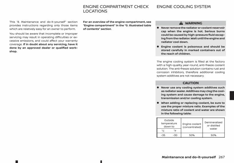
This “8. Maintenance and do-it-yourself” sectionprovides instructions regarding only those itemswhich are relatively easy for an owner to perform.
You should be aware that incomplete or improperservicing may result in operating difficulties or ex-cessive emissions, and could affect your warrantycoverage. If in doubt about any servicing, have itdone by an approved dealer or qualified work-shop.
For an overview of the engine compartment, see“Engine compartment” in the “0. Illustrated tableof contents” section.
WARNING• Never remove the radiator or coolant reservoir
cap when the engine is hot. Serious burnscould be caused by high-pressure fluid escap-ing from the radiator. Wait until the engine andradiator cool down.
• Engine coolant is poisonous and should bestored carefully in marked containers out ofthe reach of children.
The engine cooling system is filled at the factorywith a high-quality, year-round, anti-freeze coolantsolution. The anti-freeze solution contains rust andcorrosion inhibitors, therefore additional coolingsystem additives are not necessary.
CAUTION• Never use any cooling system additives such
as radiator sealer. Additives may clog the cool-ing system and cause damage to the engine,transmission and/or cooling system.
• When adding or replacing coolant, be sure touse the proper mixture ratio. Examples of themixture ratio of coolant and water are shownin the following table:
Outsidetemperature
down toEngine coolant(concentrated)
Demineralisedor distilled
water°C °F
−35 −30 50% 50%
ENGINE COMPARTMENT CHECKLOCATIONS
ENGINE COOLING SYSTEM
Maintenance and do-it-yourself 267
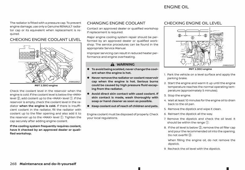
The radiator is fitted with a pressure cap. To preventengine damage, use only a Genuine RENAULT radia-tor cap or its equivalent when replacement is re-quired.
CHECKING ENGINE COOLANT LEVEL
Check the coolant level in the reservoir when theengine is cold. If the coolant level is below the <MIN>level ➁, add coolant up to the <MAX> level ➀. If thereservoir is empty, check the coolant level in the ra-diator when the engine is cold. If there is insuffi-cient coolant in the radiator, fill the radiator withcoolant up to the filler opening and also add it tothe reservoir up to the <MAX> level ➀. Tighten thecap securely after adding engine coolant.
If the cooling system frequently requires coolant,have it checked by an approved dealer or quali-fied workshop.
CHANGING ENGINE COOLANTContact an approved dealer or qualified workshopif replacement is required.
Major engine cooling system repair should be per-formed by an approved dealer or qualified work-shop. The service procedures can be found in theappropriate Service Manual.
Improper servicing can result in reduced heater per-formance and engine overheating.
WARNING• To avoid being scalded, never change the cool-
ant when the engine is hot.
• Never remove the radiator or coolant reservoircap when the engine is hot. Serious burnscould be caused by high pressure fluid escap-ing from the radiator.
• Avoid direct skin contact with used coolant. Ifskin contact is made, wash thoroughly withsoap or hand cleaner as soon as possible.
• Keep coolant out of reach of children and pets.
Engine coolant must be disposed of properly. Checkyour local regulations.
CHECKING ENGINE OIL LEVEL
1. Park the vehicle on a level surface and apply theparking brake.
2. Start the engine and warm it up until the enginetemperature reaches the normal operating tem-perature (approximately 5 minutes).
3. Stop the engine.
4. Wait at least 10 minutes for the engine oil to drainback to the oil pan.
5. Remove the dipstick and wipe it clean.
6. Reinsert the dipstick all the way.
7. Remove the dipstick and check the oil level. Itshould be within the range ➀.
8. If the oil level is below ➁, remove the oil filler capand pour the recommended oil into the opening.Do not overfill ➂.
When filling the engine oil, do not remove thedipstick.
9. Recheck the oil level with the dipstick.
JVM0528XZ
M9T 2.3DCI engine
JVM0535XZ
M9T 2.3DCI engine
ENGINE OIL
268 Maintenance and do-it-yourself
CAUTION• The oil level should be checked regularly. Op-
erating your vehicle with an insufficientamount of oil can damage the engine, andsuch damage is not covered by the warranty.
• It is normal to add some engine oil betweenoil maintenance intervals depending on theseverity of operating conditions or dependingon the property of the engine oil used. Moreengine oil is consumed by frequent accelera-tion/deceleration especially when the enginerpm is high. Consumption is likely to be higherwhen the engine is new. If the rate of oil con-sumption, after having driven for 5,000 km(3,000 miles), is more than 0.5 litre per 1,000km (621 miles), consult an approved dealer orqualified workshop.
CHANGING ENGINE OIL AND OILFILTERContact an approved dealer or qualified workshopwhen the engine oil and oil filter require replace-ment.
PROTECT ENVIRONMENTIt is illegal to pollute drains, watercourses and soil.Use authorised waste collection facilities, includingcivil amenity sites and garages providing facilitiesfor disposal of used oil and used oil filters. If in doubt,contact your local authority for advice on disposal.
The regulations concerning the pollution of theenvironment will vary from country to country.
REFILLING THE AdBlue® TANKWhen the [Refill AdBlue] warning appears in the ve-hicle information display, refill the AdBlue® tank be-fore the tank is empty (see “AdBlue® Selective Cata-lytic Reduction (SCR) system” in the “5. Starting anddriving” section for the AdBlue® warning display.)Refill the AdBlue® tank according to the proceduresshown in this section.
CAUTION• Use only AdBlue®. Using other fluids will dam-
age the AdBlue® Selective Catalytic Reduction(SCR) system.
• Be careful not to spill AdBlue®. If the AdBlue® isspilled on the vehicle body, wipe it away with awet cloth immediately to avoid paint damage.
• AdBlue® residues crystallize after a period oftime and contaminate the paint surfaces. Ifthe spilled AdBlue® has crystallized, use asponge and cold water to clean it.
• When refilling the tank completely, add the Ad-Blue® slowly to minimise the risk of spillage.
• Be careful not to inhale any ammonia vapoursthat may be released. Fill the AdBlue® tank inwell-ventilated areas.
• Driving conditions (trailer towing, driving style,etc) influence the AdBlue® consumption. Theconsumption can vary from 0.5 L/100 km (125miles/L) for severe use, to 0.1 L/100 km (625miles/L) for mild use.
The AdBlue® tank is located underneath the vehicle.(see “AdBlue® filler lid and cap” in the “3. Pre-drivingchecks and adjustments” section for the AdBlue®filler lid location.)
1. Apply the parking brake.
2. Automatic Transmission (AT) model: Move theshift lever to the P (Park) position.
Manual Transmission (MT) model: Move the shiftlever to the N (Neutral) position.
3. Place the ignition switch in the OFF position.
4. Open the AdBlue® filler lid.
5. Remove the AdBlue® tank cap by turning it anti-clockwise.
6. Refill the AdBlue® tank.
7. Securely install the AdBlue® tank cap.
8. Close the AdBlue® filler lid.
9. Place the ignition switch in the ON position andwait for approximately 1 minute until the (AdBluelow) warning turns off.
10. Start the engine.
NOTE
• In the case that the [ENG can't start RefillAdBlue] warning is displayed, place the ig-nition switch in the ON position and checkthat the warning has turned off. Then, startthe engine.
AdBlue® TANK (where fitted for diesel engine model)
Maintenance and do-it-yourself 269
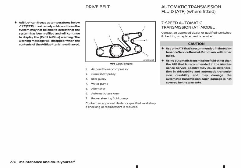
• AdBlue® can freeze at temperatures below-11°C (12°F). In extremely cold conditions thesystem may not be able to detect that thesystem has been refilled and will continueto display the [Refill AdBlue] warning. Thewarning message will disappear when thecontents of the AdBlue® tank have thawed.
1. Air conditioner compressor
2. Crankshaft pulley
3. Idler pulley
4. Water pump
5. Alternator
6. Automatic tensioner
7. Power steering fluid pump
Contact an approved dealer or qualified workshopif checking or replacement is required.
7-SPEED AUTOMATICTRANSMISSION (AT) MODELContact an approved dealer or qualified workshopif checking or replacement is required.
CAUTION• Use only ATF that is recommended in the Main-
tenance Service Booklet. Do not mix with otherfluids.
• Using automatic transmission fluid other thanthe ATF that is recommended in the Mainte-nance Service Booklet may cause deteriora-tion in driveability and automatic transmis-sion durability and may damage theautomatic transmission. Such damage is notcovered by the warranty.
JVM0534XZ
M9T 2.3DCI engine
DRIVE BELT AUTOMATIC TRANSMISSIONFLUID (ATF) (where fitted)
270 Maintenance and do-it-yourself
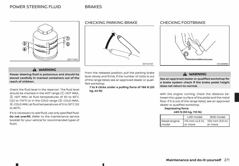
WARNINGPower steering fluid is poisonous and should bestored carefully in marked containers out of thereach of children.
Check the fluid level in the reservoir. The fluid levelshould be checked in the HOT range (➀: HOT MAX.,➁: HOT MIN.) at fluid temperatures of 50 to 80°C(122 to 176°F) or in the COLD range (➂: COLD MAX.,➃: COLD MIN.) at fluid temperatures of 0 to 30°C (32to 86°F).
If it is necessary to add fluid, use only specified fluid.Do not overfill. (Refer to the maintenance servicebooklet for your vehicle for recommended types offluid.)
CHECKING PARKING BRAKE
From the released position, pull the parking brakelever slowly and firmly. If the number of clicks is outof the range listed, see an approved dealer or quali-fied workshop.
7 to 9 clicks under a pulling force of 196 N (20kg, 44 lb)
CHECKING FOOTBRAKE
WARNINGSee an approved dealer or qualified workshop fora brake system check if the brake pedal heightdoes not return to normal.
With the engine running, check the distance be-tween the upper surface of the pedal and the metalfloor. If it is out of the range listed, see an approveddealer or qualified workshop.
Depressing force490 N (50 kg, 110 lb)
LHD model RHD modelDiesel enginemodel
110 mm (4.3 in)or more
100 mm (3.9 in)or more
SDI1718AZ
SDI1447AZ DI1020MMZ
POWER STEERING FLUID BRAKES
Maintenance and do-it-yourself 271
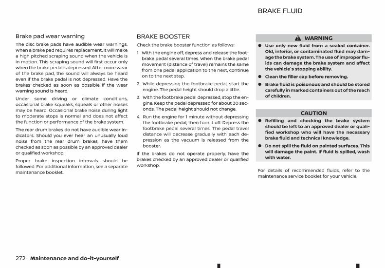
Brake pad wear warningThe disc brake pads have audible wear warnings.When a brake pad requires replacement, it will makea high pitched scraping sound when the vehicle isin motion. This scraping sound will first occur onlywhen the brake pedal is depressed. After more wearof the brake pad, the sound will always be heardeven if the brake pedal is not depressed. Have thebrakes checked as soon as possible if the wearwarning sound is heard.
Under some driving or climate conditions,occasional brake squeaks, squeals or other noisesmay be heard. Occasional brake noise during lightto moderate stops is normal and does not affectthe function or performance of the brake system.
The rear drum brakes do not have audible wear in-dicators. Should you ever hear an unusually loudnoise from the rear drum brakes, have themchecked as soon as possible by an approved dealeror qualified workshop.
Proper brake inspection intervals should befollowed. For additional information, see a separatemaintenance booklet.
BRAKE BOOSTERCheck the brake booster function as follows:
1. With the engine off, depress and release the foot-brake pedal several times. When the brake pedalmovement (distance of travel) remains the samefrom one pedal application to the next, continueon to the next step.
2. While depressing the footbrake pedal, start theengine. The pedal height should drop a little.
3. With the footbrake pedal depressed, stop the en-gine. Keep the pedal depressed for about 30 sec-onds. The pedal height should not change.
4. Run the engine for 1 minute without depressingthe footbrake pedal, then turn it off. Depress thefootbrake pedal several times. The pedal traveldistance will decrease gradually with each de-pression as the vacuum is released from thebooster.
If the brakes do not operate properly, have thebrakes checked by an approved dealer or qualifiedworkshop.
WARNING• Use only new fluid from a sealed container.
Old, inferior, or contaminated fluid may dam-age the brake system. The use of improper flu-ids can damage the brake system and affectthe vehicle's stopping ability.
• Clean the filler cap before removing.
• Brake fluid is poisonous and should be storedcarefully in marked containers out of the reachof children.
CAUTION• Refilling and checking the brake system
should be left to an approved dealer or quali-fied workshop who will have the necessarybrake fluid and technical knowledge.
• Do not spill the fluid on painted surfaces. Thiswill damage the paint. If fluid is spilled, washwith water.
For details of recommended fluids, refer to themaintenance service booklet for your vehicle.
BRAKE FLUID
272 Maintenance and do-it-yourself
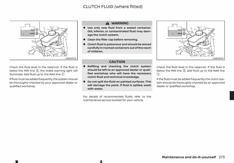
Check the fluid level in the reservoir. If the fluid isbelow the MIN line ➁, the brake warning light willilluminate. Add fluid up to the MAX line ➀.
If fluid must be added frequently, the system shouldbe thoroughly checked by your approved dealer orqualified workshop.
WARNING• Use only new fluid from a sealed container.
Old, inferior, or contaminated fluid may dam-age the clutch system.
• Clean the filler cap before removing.
• Clutch fluid is poisonous and should be storedcarefully in marked containers out of the reachof children.
CAUTION• Refilling and checking the clutch system
should be left to an approved dealer or quali-fied workshop who will have the necessaryclutch fluid and technical knowledge.
• Do not spill the fluid on painted surfaces. Thiswill damage the paint. If fluid is spilled, washwith water.
For details of recommended fluids, refer to themaintenance service booklet for your vehicle.
Check the fluid level in the reservoir. If the fluid isbelow the MIN line ➁, add fluid up to the MAX line➀.
If the fluid must be added frequently, the clutch sys-tem should be thoroughly checked by an approveddealer or qualified workshop.
JVM0450XZ JVM0450XZ
CLUTCH FLUID (where fitted)
Maintenance and do-it-yourself 273
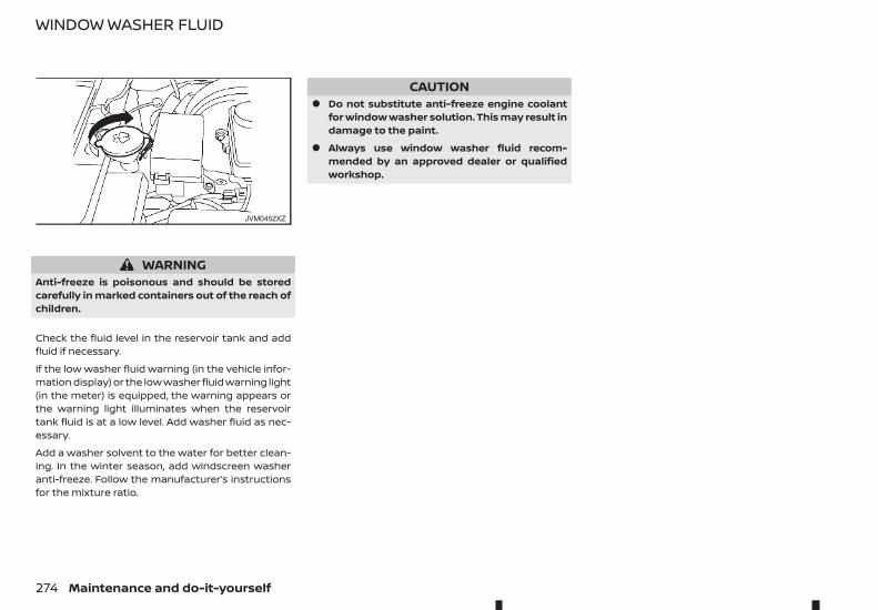
WARNINGAnti-freeze is poisonous and should be storedcarefully in marked containers out of the reach ofchildren.
Check the fluid level in the reservoir tank and addfluid if necessary.
If the low washer fluid warning (in the vehicle infor-mation display) or the low washer fluid warning light(in the meter) is equipped, the warning appears orthe warning light illuminates when the reservoirtank fluid is at a low level. Add washer fluid as nec-essary.
Add a washer solvent to the water for better clean-ing. In the winter season, add windscreen washeranti-freeze. Follow the manufacturer’s instructionsfor the mixture ratio.
CAUTION• Do not substitute anti-freeze engine coolant
for window washer solution. This may result indamage to the paint.
• Always use window washer fluid recom-mended by an approved dealer or qualifiedworkshop.
JVM0452XZ
WINDOW WASHER FLUID
274 Maintenance and do-it-yourself
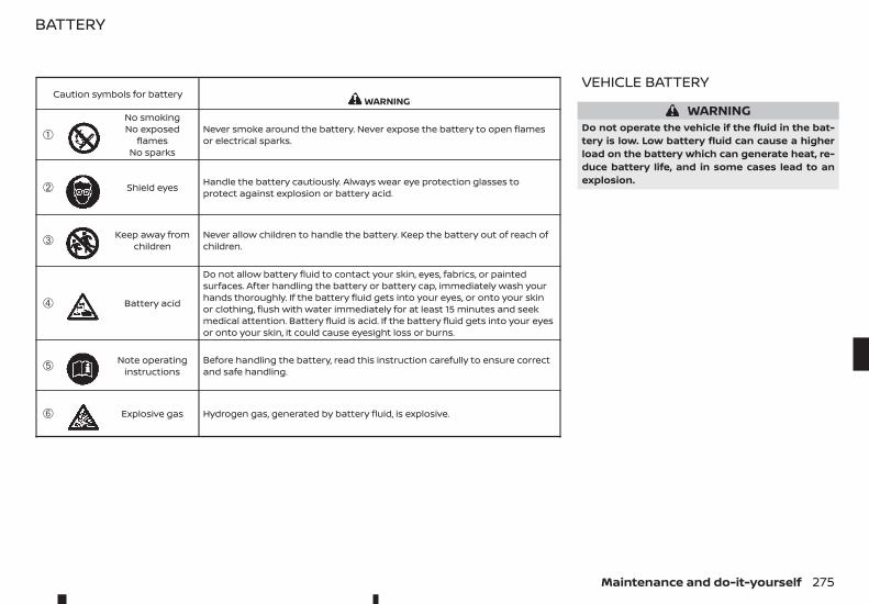
VEHICLE BATTERY
WARNINGDo not operate the vehicle if the fluid in the bat-tery is low. Low battery fluid can cause a higherload on the battery which can generate heat, re-duce battery life, and in some cases lead to anexplosion.
Caution symbols for battery m WARNING
➀ mNo smokingNo exposed
flamesNo sparks
Never smoke around the battery. Never expose the battery to open flamesor electrical sparks.
➁ m Shield eyes Handle the battery cautiously. Always wear eye protection glasses toprotect against explosion or battery acid.
➂ m Keep away fromchildren
Never allow children to handle the battery. Keep the battery out of reach ofchildren.
➃ m Battery acid
Do not allow battery fluid to contact your skin, eyes, fabrics, or paintedsurfaces. After handling the battery or battery cap, immediately wash yourhands thoroughly. If the battery fluid gets into your eyes, or onto your skinor clothing, flush with water immediately for at least 15 minutes and seekmedical attention. Battery fluid is acid. If the battery fluid gets into your eyesor onto your skin, it could cause eyesight loss or burns.
➄ m Note operatinginstructions
Before handling the battery, read this instruction carefully to ensure correctand safe handling.
➅ m Explosive gas Hydrogen gas, generated by battery fluid, is explosive.
BATTERY
Maintenance and do-it-yourself 275
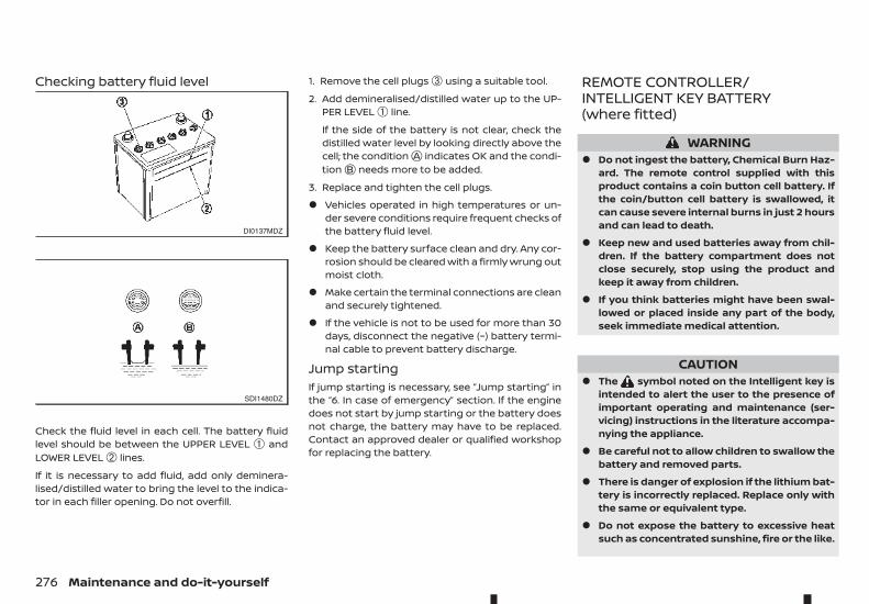
Checking battery fluid level
Check the fluid level in each cell. The battery fluidlevel should be between the UPPER LEVEL ➀ andLOWER LEVEL ➁ lines.
If it is necessary to add fluid, add only deminera-lised/distilled water to bring the level to the indica-tor in each filler opening. Do not overfill.
1. Remove the cell plugs ➂ using a suitable tool.
2. Add demineralised/distilled water up to the UP-PER LEVEL ➀ line.
If the side of the battery is not clear, check thedistilled water level by looking directly above thecell; the conditionjA indicates OK and the condi-tionjB needs more to be added.
3. Replace and tighten the cell plugs.
• Vehicles operated in high temperatures or un-der severe conditions require frequent checks ofthe battery fluid level.
• Keep the battery surface clean and dry. Any cor-rosion should be cleared with a firmly wrung outmoist cloth.
• Make certain the terminal connections are cleanand securely tightened.
• If the vehicle is not to be used for more than 30days, disconnect the negative (−) battery termi-nal cable to prevent battery discharge.
Jump startingIf jump starting is necessary, see “Jump starting” inthe “6. In case of emergency” section. If the enginedoes not start by jump starting or the battery doesnot charge, the battery may have to be replaced.Contact an approved dealer or qualified workshopfor replacing the battery.
REMOTE CONTROLLER/INTELLIGENT KEY BATTERY(where fitted)
WARNING• Do not ingest the battery, Chemical Burn Haz-
ard. The remote control supplied with thisproduct contains a coin button cell battery. Ifthe coin/button cell battery is swallowed, itcan cause severe internal burns in just 2 hoursand can lead to death.
• Keep new and used batteries away from chil-dren. If the battery compartment does notclose securely, stop using the product andkeep it away from children.
• If you think batteries might have been swal-lowed or placed inside any part of the body,seek immediate medical attention.
CAUTION• The symbol noted on the Intelligent key is
intended to alert the user to the presence ofimportant operating and maintenance (ser-vicing) instructions in the literature accompa-nying the appliance.
• Be careful not to allow children to swallow thebattery and removed parts.
• There is danger of explosion if the lithium bat-tery is incorrectly replaced. Replace only withthe same or equivalent type.
• Do not expose the battery to excessive heatsuch as concentrated sunshine, fire or the like.
DI0137MDZ
SDI1480DZ
276 Maintenance and do-it-yourself

• Do not crush or cut the battery.
• Do not subject the battery to extremely lowair pressure at high altitude.
• When changing batteries, do not let dust or oilget on the components.
• Be careful not to touch a circuit board or a bat-tery terminal.
• An improperly disposed battery can harm theenvironment. Always conform to local regula-tions for battery disposal.
• The Integrated key fob/Intelligent Key is wa-ter-resistant; however, if it does get wet, im-mediately wipe it until it gets completely dry.To replace the battery, open the Integrated keyfob/Intelligent Key carefully in the sequenceshown in the illustration.
• When changing the battery, do not let dust oroil get on the Integrated key fob/IntelligentKey.
CAUTIONAlways hold the battery by the edges, as shown.Holding the battery across the contact points willseriously deplete the storage capacity.
Remote controller battery replacementTo replace the battery:
1. Use an appropriate tool to remove the screwjA and open the lidjB .
SPA0784Z
SDI2134A
Maintenance and do-it-yourself 277
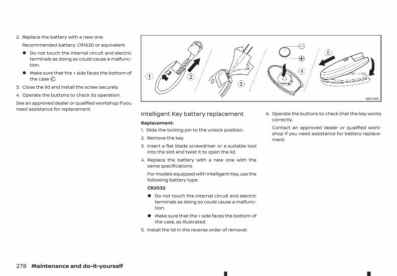
2. Replace the battery with a new one.
Recommended battery: CR1620 or equivalent
• Do not touch the internal circuit and electricterminals as doing so could cause a malfunc-tion.
• Make sure that the + side faces the bottom ofthe casejC .
3. Close the lid and install the screw securely.
4. Operate the buttons to check its operation.
See an approved dealer or qualified workshop if youneed assistance for replacement.
Intelligent Key battery replacementReplacement:1. Slide the locking pin to the unlock position.
2. Remove the key.
3. Insert a flat blade screwdriver or a suitable toolinto the slot and twist it to open the lid.
4. Replace the battery with a new one with thesame specifications.
For models equipped with Intelligent Key, use thefollowing battery type:
CR2032
• Do not touch the internal circuit and electricterminals as doing so could cause a malfunc-tion.
• Make sure that the + side faces the bottom ofthe case, as illustrated.
5. Install the lid in the reverse order of removal.
6. Operate the buttons to check that the key workscorrectly.
Contact an approved dealer or qualified work-shop if you need assistance for battery replace-ment.
NDI1455
278 Maintenance and do-it-yourself
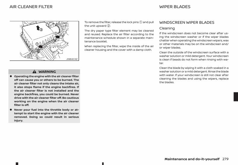
WARNING• Operating the engine with the air cleaner filter
off can cause you or others to be burned. Theair cleaner filter not only cleans the intake air,it also stops flame if the engine backfires. Ifthe air cleaner filter is not installed and theengine backfires, you could be burned. Neverdrive with the air cleaner filter off. Be cautiousworking on the engine when the air cleanerfilter is off.
• Never pour fuel into the throttle body or at-tempt to start the engine with the air cleanerremoved. Doing so could result in seriousinjury.
To remove the filter, release the lock pins ➀ and pullthe unit upward ➁.
The dry paper type filter element may be cleanedand reused. Replace the air filter according to themaintenance schedule shown in a separate main-tenance booklet.
When replacing the filter, wipe the inside of the aircleaner housing and the cover with a damp cloth.
WINDSCREEN WIPER BLADESCleaningIf the windscreen does not become clear after us-ing the windscreen washer or if the wiper bladeschatter when operating the windscreen wipers, waxor other materials may be on the windscreen and/or wiper blades.
Clean the outside of the windscreen surface with awasher solution or mild detergent. Your windscreenis clean if beads do not form when rinsing with wa-ter.
Clean the blade by wiping it with a cloth soaked in awasher solution or a mild detergent. Rinse the bladewith water. If your windscreen is still not clear aftercleaning the blades and using the wipers, replacethe blades.
JVM0451XZ
AIR CLEANER FILTER WIPER BLADES
Maintenance and do-it-yourself 279
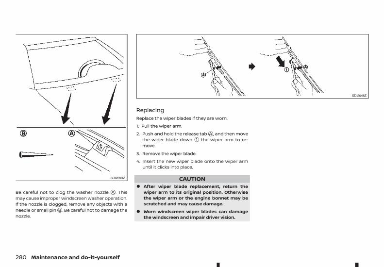
Be careful not to clog the washer nozzle jA . Thismay cause improper windscreen washer operation.If the nozzle is clogged, remove any objects with aneedle or small pinjB . Be careful not to damage thenozzle.
ReplacingReplace the wiper blades if they are worn.
1. Pull the wiper arm.
2. Push and hold the release tabjA , and then movethe wiper blade down ➀ the wiper arm to re-move.
3. Remove the wiper blade.
4. Insert the new wiper blade onto the wiper armuntil it clicks into place.
CAUTION• After wiper blade replacement, return the
wiper arm to its original position. Otherwisethe wiper arm or the engine bonnet may bescratched and may cause damage.
• Worn windscreen wiper blades can damagethe windscreen and impair driver vision.
SDI2693Z
SDI2048Z
280 Maintenance and do-it-yourself
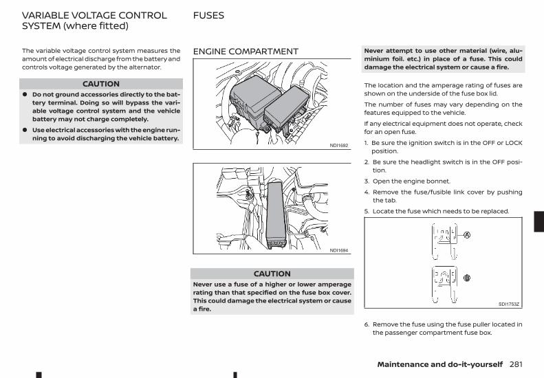
The variable voltage control system measures theamount of electrical discharge from the battery andcontrols voltage generated by the alternator.
CAUTION• Do not ground accessories directly to the bat-
tery terminal. Doing so will bypass the vari-able voltage control system and the vehiclebattery may not charge completely.
• Use electrical accessories with the engine run-ning to avoid discharging the vehicle battery.
ENGINE COMPARTMENT
CAUTIONNever use a fuse of a higher or lower amperagerating than that specified on the fuse box cover.This could damage the electrical system or causea fire.
Never attempt to use other material (wire, alu-minium foil. etc.) in place of a fuse. This coulddamage the electrical system or cause a fire.
The location and the amperage rating of fuses areshown on the underside of the fuse box lid.
The number of fuses may vary depending on thefeatures equipped to the vehicle.
If any electrical equipment does not operate, checkfor an open fuse.
1. Be sure the ignition switch is in the OFF or LOCKposition.
2. Be sure the headlight switch is in the OFF posi-tion.
3. Open the engine bonnet.
4. Remove the fuse/fusible link cover by pushingthe tab.
5. Locate the fuse which needs to be replaced.
6. Remove the fuse using the fuse puller located inthe passenger compartment fuse box.
NDI1692
NDI1694
SDI1753Z
VARIABLE VOLTAGE CONTROLSYSTEM (where fitted)
FUSES
Maintenance and do-it-yourself 281
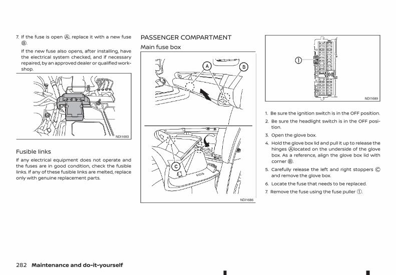
7. If the fuse is openjA , replace it with a new fusejB .
If the new fuse also opens, after installing, havethe electrical system checked, and if necessaryrepaired, by an approved dealer or qualified work-shop.
Fusible linksIf any electrical equipment does not operate andthe fuses are in good condition, check the fusiblelinks. If any of these fusible links are melted, replaceonly with genuine replacement parts.
PASSENGER COMPARTMENTMain fuse box
1. Be sure the ignition switch is in the OFF position.
2. Be sure the headlight switch is in the OFF posi-tion.
3. Open the glove box.
4. Hold the glove box lid and pull it up to release thehingesjA located on the underside of the glovebox. As a reference, align the glove box lid withcornerjB .
5. Carefully release the left and right stoppers jCand remove the glove box.
6. Locate the fuse that needs to be replaced.
7. Remove the fuse using the fuse puller ➀.
NDI1693
NDI1686
NDI1689
282 Maintenance and do-it-yourself
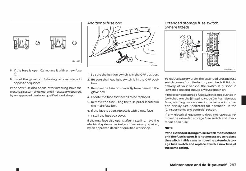
8. If the fuse is open ➁, replace it with a new fuse➂.
9. Install the glove box following removal steps inopposite sequence.
If the new fuse also opens, after installing, have theelectrical system checked, and if necessary repaired,by an approved dealer or qualified workshop.
Additional fuse box
1. Be sure the ignition switch is in the OFF position.
2. Be sure the headlight switch is in the OFF posi-tion.
3. Remove the fuse box coverjA from beneath theglove box.
4. Locate the fuse that needs to be replaced.
5. Remove the fuse using the fuse puller located inthe main fuse box.
6. If the fuse is open, replace it with a new fuse.
7. Install the fuse box cover.
If the new fuse also opens, after installing, have theelectrical system checked, and if necessary repaired,by an approved dealer or qualified workshop.
Extended storage fuse switch(where fitted)
To reduce battery drain, the extended storage fuseswitch comes from the factory switched off. Prior todelivery of your vehicle, the switch is pushed in(switched on) and should always remain on.
If the extended storage fuse switch is not pushed in(switched on), the [Shipping Mode On Push StorageFuse] warning may appear in the vehicle informa-tion display. See “Indicators for operation” in the“2. Instruments and controls” section.
If any electrical equipment does not operate, re-move the extended storage fuse switch and checkfor an open fuse.
NOTE
If the extended storage fuse switch malfunctionsor if the fuse is open, it is not necessary to replacethe switch. In this case, remove the extended stor-age fuse switch and replace it with a new fuse ofthe same rating.
NDI1688
NTI386
JVM0462XZ
Maintenance and do-it-yourself 283
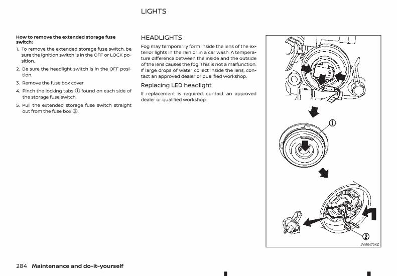
How to remove the extended storage fuseswitch:1. To remove the extended storage fuse switch, be
sure the ignition switch is in the OFF or LOCK po-sition.
2. Be sure the headlight switch is in the OFF posi-tion.
3. Remove the fuse box cover.
4. Pinch the locking tabs ➀ found on each side ofthe storage fuse switch.
5. Pull the extended storage fuse switch straightout from the fuse box ➁.
HEADLIGHTSFog may temporarily form inside the lens of the ex-terior lights in the rain or in a car wash. A tempera-ture difference between the inside and the outsideof the lens causes the fog. This is not a malfunction.If large drops of water collect inside the lens, con-tact an approved dealer or qualified workshop.
Replacing LED headlightIf replacement is required, contact an approveddealer or qualified workshop.
JVM0470XZ
LIGHTS
284 Maintenance and do-it-yourself
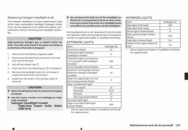
Replacing halogen headlight bulbThe halogen headlight is a semi-sealed beam typewhich uses replaceable headlight (halogen) bulbs.They can be replaced from inside the engine com-partment without removing the headlight assem-bly.
CAUTIONHigh-pressure halogen gas is sealed inside thebulb. The bulb may break if the glass envelope isscratched or the bulb is dropped.
1. Disconnect the battery negative cable.
2. Disconnect the electrical connector from therear end of the bulb.
3. Pull off the rubber cap ➀.
4. Push and turn the retaining pin ➁ to loosen it.
5. Remove the headlight bulb. Do not shake orrotate the bulb when removing it.
6. Install the new bulb in the reverse order ofremoval.
CAUTION• When handling the bulb, do not touch the glass
envelope.
• Use the same number and wattage as origi-nally installed:Halogen headlight model
High/low beam bulb: 60W/55W (H4)
• Do not leave the bulb out of the headlight re-flector for a long period of time as dust, mois-ture and smoke may enter the headlight bodyand affect the performance of the headlight.
Aiming adjustment is not necessary if only the bulbsare replaced. When aiming adjustment is necessary,contact an approved dealer or qualified workshop.
EXTERIOR LIGHTSItem Wattage (W)Front turn signal 21Clearance light (Halogenheadlight models) 5
Clearance light and daytimerunning light (LED headlightmodels)*
LED
Front fog light (where fitted) 55Daytime running light (wherefitted for halogen headlightmodels)
19
Side turn signal light (on thefront wing) (where fitted) 5
Rear combination lightTurn signal 21Stop/tail 21/5Reverse 21Rear fog (where fitted) 21
Number plate light 5High-mounted brake light(where fitted)* LED
*: See an approved dealer or qualified workshopfor replacement.
INTERIOR LIGHTSItem Wattage (W)Map light (LED type)* LEDMap light (bulb type) 5Room light (where fitted) 8Rear personal light (wherefitted) LED
Step light (where fitted) 3.4Vanity mirror light (where fit-ted) 1.8
*: See an approved dealer or qualified workshopfor replacement.
Maintenance and do-it-yourself 285
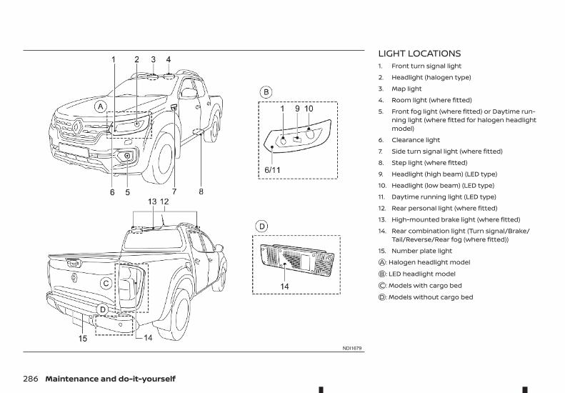
LIGHT LOCATIONS1. Front turn signal light
2. Headlight (halogen type)
3. Map light
4. Room light (where fitted)
5. Front fog light (where fitted) or Daytime run-ning light (where fitted for halogen headlightmodel)
6. Clearance light
7. Side turn signal light (where fitted)
8. Step light (where fitted)
9. Headlight (high beam) (LED type)
10. Headlight (low beam) (LED type)
11. Daytime running light (LED type)
12. Rear personal light (where fitted)
13. High-mounted brake light (where fitted)
14. Rear combination light (Turn signal/Brake/Tail/Reverse/Rear fog (where fitted))
15. Number plate lightjA : Halogen headlight modeljB : LED headlight modeljC : Models with cargo bedjD : Models without cargo bed
NDI1679
286 Maintenance and do-it-yourself
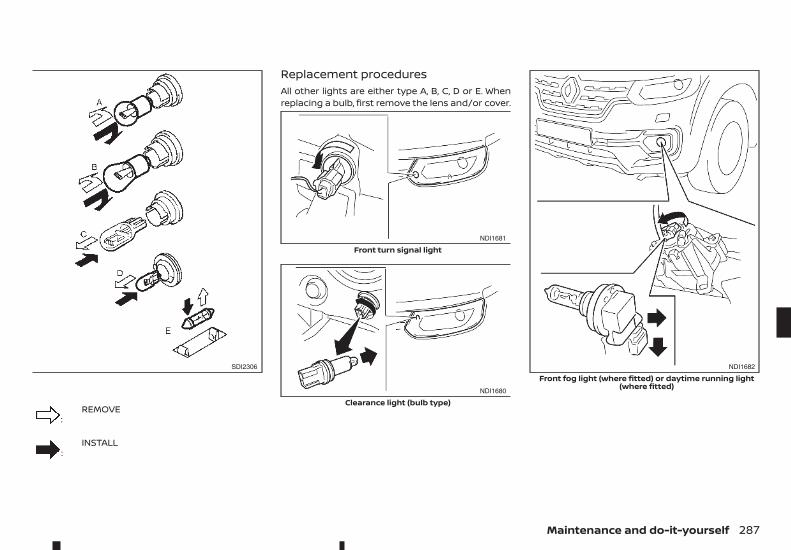
m:REMOVE
m :INSTALL
Replacement proceduresAll other lights are either type A, B, C, D or E. Whenreplacing a bulb, first remove the lens and/or cover.
SDI2306
NDI1681
Front turn signal light
NDI1680
Clearance light (bulb type)
NDI1682
Front fog light (where fitted) or daytime running light(where fitted)
Maintenance and do-it-yourself 287
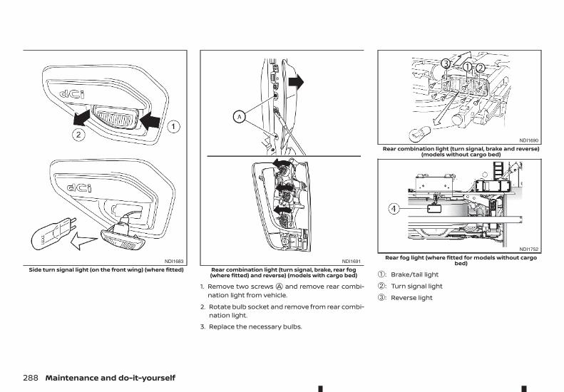
1. Remove two screwsjA and remove rear combi-nation light from vehicle.
2. Rotate bulb socket and remove from rear combi-nation light.
3. Replace the necessary bulbs.
➀: Brake/tail light
➁: Turn signal light
➂: Reverse light
NDI1683
Side turn signal light (on the front wing) (where fitted)NDI1691
Rear combination light (turn signal, brake, rear fog(where fitted) and reverse) (models with cargo bed)
NDI1690
Rear combination light (turn signal, brake and reverse)(models without cargo bed)
NDI1752
Rear fog light (where fitted for models without cargobed)
288 Maintenance and do-it-yourself
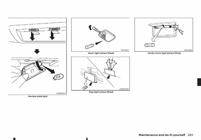
JVM0464XZ
Number plate light
SDI1845Z
Room light (where fitted)
JVM0553XZ
Step light (where fitted)
SDI1839Z
Vanity mirror light (where fitted)
Maintenance and do-it-yourself 289
If you have a flat tyre, see “Flat tyre” in the “6. In caseof emergency” section.
TYRE INFLATION PRESSUREPeriodically check the pressure of the tyres, includ-ing the spare. An incorrect tyre pressure may ad-versely affect tyre life and vehicle handling. The tyrepressure should be checked when tyres are COLD.Tyres are considered COLD after the vehicle hasbeen parked for 3 or more hours, or driven less than1.6 km (1 mile). COLD tyre pressures are shown onthe tyre placard.
Insufficient pressure can lead to an overheating ofthe tyre and subsequent internal damage. At highspeeds, this could result in tread separation andeven bursting of the tyre.
TYPES OF TYRES
CAUTIONWhen changing or replacing tyres, be sure all fourtyres are of the same type (that is, summer, allseason or snow) and construction. An approveddealer or qualified workshop may be able to helpyou with information about tyre type, size, speedrating and availability.
Replacement tyres may have a lower speed ratingthan the factory equipped tyres, and they may notmatch the potential maximum vehicle speed. Neverexceed the maximum speed rating of the tyre.
All season tyresRENAULT specifies all season tyres on some modelsto provide good performance all year, includingsnowy and icy road conditions. All season tyres areidentified by ALL SEASON and/or M&S on the tyresidewall. Snow tyres have better snow traction thanall season tyres and may be more appropriate insome areas.
Summer tyresRENAULT specifies summer tyres on some modelsto provide superior performance on dry roads. Sum-mer tyre performance is substantially reduced insnow and ice. Summer tyres do not have the tyretraction rating M&S on the tyre sidewall.
If you plan to operate your vehicle in snowy or icyconditions, RENAULT recommends the use of snowor all season tyres on all four wheels.
Snow tyresIf snow tyres are needed, it is necessary to selecttyres equivalent in size and load rating to the origi-nal equipment tyres. If you do not, it can adverselyaffect the safety and handling of your vehicle.
Generally, snow tyres have lower speed ratings thanfactory equipped tyres and may not match the po-tential maximum vehicle speed. Never exceed themaximum speed rating of the tyre. If you installsnow tyres, they must be the same size, brand, con-struction and tread pattern on all four wheels.
For additional traction on icy roads, studded tyresmay be used. However, some states and provincesprohibit their use. Check local, state and provinciallaws before installing studded tyres. Skid and trac-tion capabilities of studded snow tyres on wet ordry surfaces may be poorer than that of non-stud-ded snow tyres.
Four-Wheel Drive (4WD) model
CAUTION• Always use tyres of the same type, size, brand,
construction (bias, bias-belted or radial), andtread pattern on all four wheels. Failure to doso may result in a circumference differencebetween tyres on the front and rear axleswhich will cause excessive tyre wear and maydamage the transmission, transfer case anddifferential gears.
• ONLY use spare tyres specified for the 4WDmodel.
If excessive tyre wear is found, it is recommendedthat all four tyres be replaced with tyres of the samesize, brand, construction and tread pattern. The tyrepressure and wheel alignment should also bechecked and corrected as necessary. Contact anapproved dealer or qualified workshop.
TYRES AND WHEELS
290 Maintenance and do-it-yourself
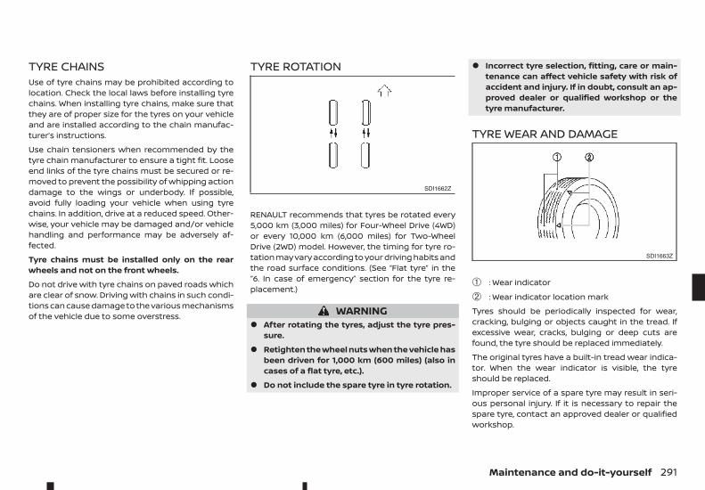
TYRE CHAINSUse of tyre chains may be prohibited according tolocation. Check the local laws before installing tyrechains. When installing tyre chains, make sure thatthey are of proper size for the tyres on your vehicleand are installed according to the chain manufac-turer’s instructions.
Use chain tensioners when recommended by thetyre chain manufacturer to ensure a tight fit. Looseend links of the tyre chains must be secured or re-moved to prevent the possibility of whipping actiondamage to the wings or underbody. If possible,avoid fully loading your vehicle when using tyrechains. In addition, drive at a reduced speed. Other-wise, your vehicle may be damaged and/or vehiclehandling and performance may be adversely af-fected.
Tyre chains must be installed only on the rearwheels and not on the front wheels.
Do not drive with tyre chains on paved roads whichare clear of snow. Driving with chains in such condi-tions can cause damage to the various mechanismsof the vehicle due to some overstress.
TYRE ROTATION
RENAULT recommends that tyres be rotated every5,000 km (3,000 miles) for Four-Wheel Drive (4WD)or every 10,000 km (6,000 miles) for Two-WheelDrive (2WD) model. However, the timing for tyre ro-tation may vary according to your driving habits andthe road surface conditions. (See “Flat tyre” in the“6. In case of emergency” section for the tyre re-placement.)
WARNING• After rotating the tyres, adjust the tyre pres-
sure.
• Retighten the wheel nuts when the vehicle hasbeen driven for 1,000 km (600 miles) (also incases of a flat tyre, etc.).
• Do not include the spare tyre in tyre rotation.
• Incorrect tyre selection, fitting, care or main-tenance can affect vehicle safety with risk ofaccident and injury. If in doubt, consult an ap-proved dealer or qualified workshop or thetyre manufacturer.
TYRE WEAR AND DAMAGE
➀ : Wear indicator
➁ : Wear indicator location mark
Tyres should be periodically inspected for wear,cracking, bulging or objects caught in the tread. Ifexcessive wear, cracks, bulging or deep cuts arefound, the tyre should be replaced immediately.
The original tyres have a built-in tread wear indica-tor. When the wear indicator is visible, the tyreshould be replaced.
Improper service of a spare tyre may result in seri-ous personal injury. If it is necessary to repair thespare tyre, contact an approved dealer or qualifiedworkshop.
SDI1662Z
SDI1663Z
Maintenance and do-it-yourself 291
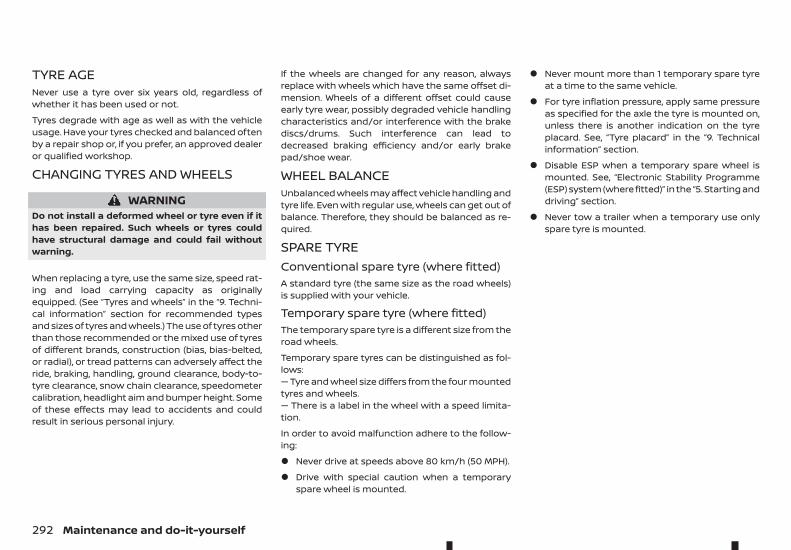
TYRE AGENever use a tyre over six years old, regardless ofwhether it has been used or not.
Tyres degrade with age as well as with the vehicleusage. Have your tyres checked and balanced oftenby a repair shop or, if you prefer, an approved dealeror qualified workshop.
CHANGING TYRES AND WHEELS
WARNINGDo not install a deformed wheel or tyre even if ithas been repaired. Such wheels or tyres couldhave structural damage and could fail withoutwarning.
When replacing a tyre, use the same size, speed rat-ing and load carrying capacity as originallyequipped. (See “Tyres and wheels” in the “9. Techni-cal information” section for recommended typesand sizes of tyres and wheels.) The use of tyres otherthan those recommended or the mixed use of tyresof different brands, construction (bias, bias-belted,or radial), or tread patterns can adversely affect theride, braking, handling, ground clearance, body-to-tyre clearance, snow chain clearance, speedometercalibration, headlight aim and bumper height. Someof these effects may lead to accidents and couldresult in serious personal injury.
If the wheels are changed for any reason, alwaysreplace with wheels which have the same offset di-mension. Wheels of a different offset could causeearly tyre wear, possibly degraded vehicle handlingcharacteristics and/or interference with the brakediscs/drums. Such interference can lead todecreased braking efficiency and/or early brakepad/shoe wear.
WHEEL BALANCEUnbalanced wheels may affect vehicle handling andtyre life. Even with regular use, wheels can get out ofbalance. Therefore, they should be balanced as re-quired.
SPARE TYREConventional spare tyre (where fitted)A standard tyre (the same size as the road wheels)is supplied with your vehicle.
Temporary spare tyre (where fitted)The temporary spare tyre is a different size from theroad wheels.
Temporary spare tyres can be distinguished as fol-lows:— Tyre and wheel size differs from the four mountedtyres and wheels.— There is a label in the wheel with a speed limita-tion.
In order to avoid malfunction adhere to the follow-ing:
• Never drive at speeds above 80 km/h (50 MPH).
• Drive with special caution when a temporaryspare wheel is mounted.
• Never mount more than 1 temporary spare tyreat a time to the same vehicle.
• For tyre inflation pressure, apply same pressureas specified for the axle the tyre is mounted on,unless there is another indication on the tyreplacard. See, “Tyre placard” in the “9. Technicalinformation” section.
• Disable ESP when a temporary spare wheel ismounted. See, “Electronic Stability Programme(ESP) system (where fitted)” in the “5. Starting anddriving” section.
• Never tow a trailer when a temporary use onlyspare tyre is mounted.
292 Maintenance and do-it-yourself
9 Technical informationTechnical information
Recommended fluids/lubricants and capacities ................ 294Fuel information ................................................................................... 294Automatic Transmission Fluid (ATF) ...................................... 294Air conditioner system refrigerant andlubricant...................................................................................................... 294
Engine................................................................................................................... 295Tyres and wheels ......................................................................................... 296Dimensions....................................................................................................... 297
Double Cab............................................................................................... 297When travelling or registering in another country............. 298
Vehicle identification................................................................................. 298Vehicle identification label............................................................ 298Vehicle Identification Number (VIN) plate ......................... 298Vehicle Identification Number (VIN)....................................... 298Engine serial number........................................................................ 298Tyre placard ............................................................................................. 299Air conditioner specification label .......................................... 299
Installation of an RF transmitter ...................................................... 299Radio approval number and information .................................300
Radio frequency approval.............................................................300
Refer to the maintenance service booklet for yourvehicle for details of recommended fluids/lubricants and capacities.
FUEL INFORMATIONDiesel engine*
Compatible Fuels for Diesel EngineThe diesel engine is compatible with current andfuture European standards for bio-fuel.
mDiesel conforming to EN16734 andmixed with a bio-fuel conforming toEN14214 (incorporating between 0 and10% Fatty Acid Methyl Esters).
M9T 2.3DCI engine:
Diesel fuel above 50 cetane and with less than 10ppm of sulphur (EN590) must be used.
* If two types of diesel fuel are available, usesummer or winter fuel properly according tothe following temperature conditions.
• Above –7°C (20°F) ... Summer type diesel fuel.
• Below –7°C (20°F) ... Winter type diesel fuel.
CAUTION• Do not use home heating oil, petrol or other
alternate fuels in your diesel engine. The useof those or adding those to diesel fuel cancause engine damage.
• Do not use summer fuel at temperatures be-low –7°C (20°F). The cold temperatures willcause wax to form in the fuel. As a result, itmay prevent the engine from runningsmoothly.
AUTOMATIC TRANSMISSION FLUID(ATF)Contact an approved dealer or qualified workshopif checking or replacement is required.
CAUTION• Use only ATF that is recommended in the Main-
tenance Service Booklet. Do not mix with otherfluids.
• Using automatic transmission fluid other thanthe ATF that is recommended in the Mainte-nance Service Booklet may cause deteriora-tion in driveability and automatic transmis-sion durability and may damage theautomatic transmission. Such damage is notcovered by the warranty.
AIR CONDITIONER SYSTEMREFRIGERANT AND LUBRICANTThe air conditioner system of your vehicle must becharged with the refrigerant HFC-134a (R134a) andthe lubricant specified in the maintenance servicebooklet for your vehicle.
CAUTIONUse of any other refrigerants or lubricants willcause severe damage, and you may need to re-place your vehicle’s entire air conditioner system.
The release of refrigerants into the atmosphere isprohibited in many countries and regions. The re-frigerant HFC-134a (R-134a) in your vehicle will notharm the Earth’s ozone layer. However, it may con-tribute in a small part to the global warming effect.RENAULT recommends that the refrigerant be ap-propriately recovered and recycled. Contact an ap-proved dealer or qualified workshop when servic-ing the air conditioner system.
RECOMMENDED FLUIDS/LUBRICANTS AND CAPACITIES
294 Technical information
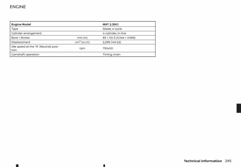
Engine Model M9T 2.3DCIType Diesel, 4-cycleCylinder arrangement 4-cylinder, in-lineBore × Stroke mm (in) 85 × 101.3 (3.346 × 3.988)Displacement cm3 (cu in) 2,298 (140.22)Idle speed at the “N” (Neutral) posi-tion rpm 750±50
Camshaft operation Timing chain
ENGINE
Technical information 295
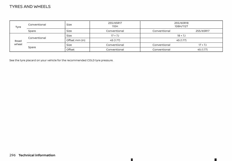
TyreConventional Size 255/65R17
110H255/60R18108H/112T
Spare Size Conventional Conventional 255/65R17
Roadwheel
ConventionalSize 17 × 7J 18 × 7J
Offset mm (in) 45 (1.77) 45 (1.77)
SpareSize Conventional Conventional 17 × 7J
Offset Conventional Conventional 45 (1.77)
See the tyre placard on your vehicle for the recommended COLD tyre pressure.
TYRES AND WHEELS
296 Technical information
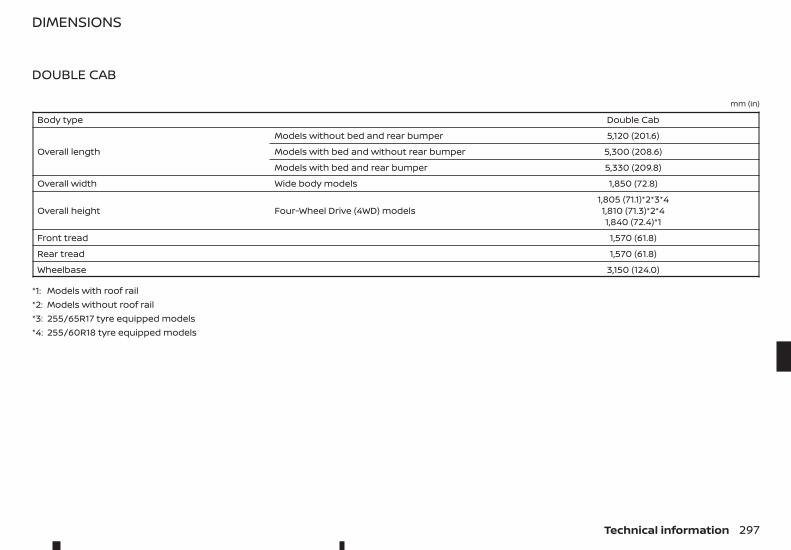
DOUBLE CAB
mm (in)
Body type Double Cab
Overall length
Models without bed and rear bumper 5,120 (201.6)
Models with bed and without rear bumper 5,300 (208.6)
Models with bed and rear bumper 5,330 (209.8)
Overall width Wide body models 1,850 (72.8)
Overall height Four-Wheel Drive (4WD) models1,805 (71.1)*2*3*41,810 (71.3)*2*41,840 (72.4)*1
Front tread 1,570 (61.8)
Rear tread 1,570 (61.8)
Wheelbase 3,150 (124.0)
*1: Models with roof rail*2: Models without roof rail*3: 255/65R17 tyre equipped models*4: 255/60R18 tyre equipped models
DIMENSIONS
Technical information 297
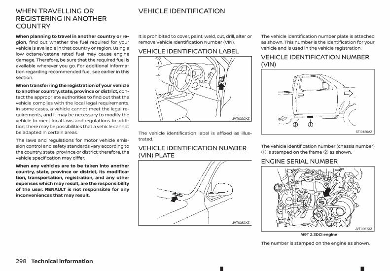
When planning to travel in another country or re-gion, find out whether the fuel required for yourvehicle is available in that country or region. Using alow octane/cetane rated fuel may cause enginedamage. Therefore, be sure that the required fuel isavailable wherever you go. For additional informa-tion regarding recommended fuel, see earlier in thissection.
When transferring the registration of your vehicleto another country, state, province or district, con-tact the appropriate authorities to find out that thevehicle complies with the local legal requirements.In some cases, a vehicle cannot meet the legal re-quirements, and it may be necessary to modify thevehicle to meet local laws and regulations. In addi-tion, there may be possibilities that a vehicle cannotbe adapted in certain areas.
The laws and regulations for motor vehicle emis-sion control and safety standards vary according tothe country, state, province or district; therefore, thevehicle specification may differ.
When any vehicles are to be taken into anothercountry, state, province or district, its modifica-tion, transportation, registration, and any otherexpenses which may result, are the responsibilityof the user. RENAULT is not responsible for anyinconveniences that may result.
It is prohibited to cover, paint, weld, cut, drill, alter orremove Vehicle Identification Number (VIN).
VEHICLE IDENTIFICATION LABEL
The vehicle identification label is affixed as illus-trated.
VEHICLE IDENTIFICATION NUMBER(VIN) PLATE
The vehicle identification number plate is attachedas shown. This number is the identification for yourvehicle and is used in the vehicle registration.
VEHICLE IDENTIFICATION NUMBER(VIN)
The vehicle identification number (chassis number)➀ is stamped on the frame ➁ as shown.
ENGINE SERIAL NUMBER
The number is stamped on the engine as shown.
JVT0330XZ
JVT0352XZ
STI0120AZ
JVT0367XZ
M9T 2.3DCI engine
WHEN TRAVELLING ORREGISTERING IN ANOTHERCOUNTRY
VEHICLE IDENTIFICATION
298 Technical information
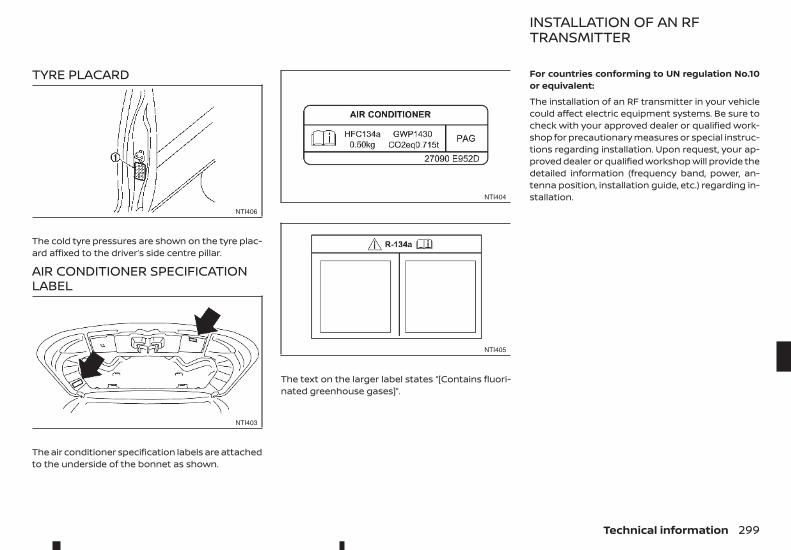
TYRE PLACARD
The cold tyre pressures are shown on the tyre plac-ard affixed to the driver’s side centre pillar.
AIR CONDITIONER SPECIFICATIONLABEL
The air conditioner specification labels are attachedto the underside of the bonnet as shown.
The text on the larger label states “[Contains fluori-nated greenhouse gases]”.
For countries conforming to UN regulation No.10or equivalent:
The installation of an RF transmitter in your vehiclecould affect electric equipment systems. Be sure tocheck with your approved dealer or qualified work-shop for precautionary measures or special instruc-tions regarding installation. Upon request, your ap-proved dealer or qualified workshop will provide thedetailed information (frequency band, power, an-tenna position, installation guide, etc.) regarding in-stallation.
NTI406
NTI403
NTI404
NTI405
INSTALLATION OF AN RFTRANSMITTER
Technical information 299
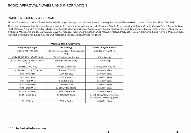
RADIO FREQUENCY APPROVALAll radio frequency products fitted to the vehicle range during production conform to the requirements of the Radio Equipment Directive (RED) 2014/53/EU.
The countries covered by this directive, or those which accept it, are: Albania, Austria, Belgium, Bosnia & Herzegovina, Bulgaria, Croatia, Cyprus, Czech Republic, Den-mark, Estonia, Finland, France, French Guyana, Georgia, Germany, Greece, Guadeloupe, Hungary, Iceland, Ireland, Italy, Kosovo, Latvia, Liechtenstein, Lithuania, Lux-embourg, Macedonia, Malta, Martinique, Mayotte, Monaco, Montenegro, Netherlands, Norway, Poland, Portugal, Reunion, Romania, Saint Pierre & Miquelon, SanMarino, Slovakia, Slovenia, Spain, Sweden, Switzerland, Turkey, Tuvalu, United Kingdom.
VEHICLE RADIO FUNCTIONSFrequency Range Technology Power/Magnetic Field
125 kHz (119 – 135 kHz) Remote Keyless Entry TransponderRing
≤ 42 dBμA/m at 10 m
433 MHz (433.05 – 434.79 MHz) Tyre Pressure Monitoring ≤ 10 mW e.r.p.433.92 MHz (433.05 MHz – 434.79
MHz)Remote Keyless Entry ≤ 10 mW e.r.p.
20 kHz (9 – 90 kHz) Keyless Go system ≤ 72 dBμA/m at 10 m2.4 GHz (2400 – 2483.5 MHz) Bluetooth®, Wi-Fi ≤ 100 mW e.i.r.p.
824 – 894 MHz GSM 850 (2G) ≤ 39 dBm e.i.r.p.880 – 960 MHz GSM 900 (2G) ≤ 39 dBm e.i.r.p.1710 – 1880 MHz GSM 1800 (2G) ≤ 36 dBm e.i.r.p.1850 – 1890 MHz GSM 1900 (2G) ≤ 33 dBm e.i.r.p.1922 – 2168 MHz W-CDMA Band I (3G) ≤ 24 dBm e.i.r.p.
24.05 – 24.25 GHz 24 GHz ISM Radar ≤ 100 mW e.i.r.p.24.25 – 26.65 GHz 24 GHz UWB Radar ≤ -41,3 dBm/MHz e.i.r.p. mean
≤ 0 dBm/50MHz e.i.r.p. peak76 – 77 GHz 77 GHz Radar ≤ 55 dBm e.i.r.p.
RADIO APPROVAL NUMBER AND INFORMATION
300 Technical information
10 IndexIndex
A
Active Emergency Braking system .............................................. 221AdBlue® .................................................................................................. 192, 269– Filler lid ....................................................................................................... 114Aids– Intelligent Around-View Monitor ........................................... 127Air bags– Front passenger air bag switch ............................................... 49– Overview ....................................................................................................... 2– Repair and replacement ................................................................ 52– Status light ............................................................................................... 63– Supplemental Restraint System (SRS) ................................ 42Air cleaner filter .......................................................................................... 279Air conditioner– Refrigerant and lubricant .......................................................... 294– Specification label ........................................................................... 299– Vents ........................................................................................................... 136Air fresheners .............................................................................................. 260Anti-Lock Braking System (ABS) ................................................... 235– Electronic Stability Programme (ESP) ................................ 219– Self test .................................................................................................... 236Approval numbers .................................................................................. 300Audible reminders ............................................................................... 57, 64Audio– Bluetooth® audio streaming main operation .............. 162– FM AM DAB radio with CD (Type B) ...................................... 166– FM AM radio with CD (Type A) .................................................. 152– IPod player operation .................................................................... 159– Steering-wheel switches ............................................................ 180– Touchscreen Navigation ............................................................. 180
Automatic transmission (AT)– Automatic transmission fluid (ATF) .................................... 270– Operation ............................................................................................... 205– Shift lock release .............................................................................. 207– Shifting .................................................................................................... 206– Starting ................................................................................................... 205
B
Battery .............................................................................................................. 275– Caution label ........................................................................................ 275– Checking fluid level ......................................................................... 276– Cold weather ....................................................................................... 237– Jump starting ..................................................................................... 250– Key battery replacement ............................................................ 277– Saver system ........................................................................................ 104– Variable voltage control system ............................................ 281– Vehicle battery ................................................................................... 275Bluetooth®– Hands-Free Phone System ........................................................ 182– Operation ................................................................................................ 160– Phone settings .................................................................................... 182– Settings .................................................................................................... 160Brakes ...................................................................................................... 235, 271– Active Emergency Braking system ...................................... 221– Anti-lock Braking System (ABS) ............................................. 235– Booster ..................................................................................................... 272– Checking footbrake ......................................................................... 271– Checking parking brake ............................................................... 271– Electronic Stability Programme (ESP) ................................ 219– Fluid ................................................................................................. 272, 294
– Pad wear warning ............................................................................ 272– Precautions ........................................................................................... 235
C
Capacities and recommendations– Brake and clutch fluid ................................................................... 294– Coolant .................................................................................................... 294– Fuel ............................................................................................................. 294– Oil ................................................................................................................. 294– Refrigerant ............................................................................................ 294Cargo– Bed ................................................................................................................ 115Changing– Engine oil filter .................................................................................... 269– Flat tyre .................................................................................................... 242Checking– Battery fluid level .............................................................................. 276– Brake pedal ............................................................................................ 271– Engine oil level .................................................................................... 268– Parking brake ....................................................................................... 271Child restraints .............................................................................................. 26– Anchorage ........................................................................................ 32, 33– ISOFIX ............................................................................................ 30, 31, 34– Precautions ............................................................................................. 26– Seat belt installation ......................................................................... 37– Universal child restraints (front and rear seats) ........... 27Child safety– Seat belts ................................................................................................... 23Cleaning– Chrome parts ...................................................................................... 259– Exterior .................................................................................................... 258– Floor mats ............................................................................................. 260– Glass ................................................................................................ 259, 260– Headlights ................................................................................................ 83
– Interior ..................................................................................................... 260– Seat belts ................................................................................................. 261– Side step boards ............................................................................... 259– Underbody ............................................................................................ 259– Washing ................................................................................................... 258– Waxing ...................................................................................................... 259– Wheels ...................................................................................................... 259– Window washer nozzle ................................................................ 279Clock ...................................................................................................................... 77Clutch– Fluid ................................................................................................. 273, 294Cockpit– Overview ....................................................................................................... 6Cold weather ............................................................................................... 236– Battery ...................................................................................................... 237– Corrosion protection ..................................................................... 237– Engine coolant ................................................................................... 237– Parking brake ...................................................................................... 237– Tyre equipment ................................................................................. 237– Winter equipment ............................................................................ 237Compass– Vehicle information display .......................................................... 71Console box .................................................................................................... 86Console side pockets ............................................................................... 87Coolant– Capacity .................................................................................................. 294– Changing engine coolant .......................................................... 268– Checking coolant level ................................................................. 268– Cold weather ....................................................................................... 237– Engine cooling system ................................................................. 267Corrosion protection .............................................................................. 261– Cold weather ....................................................................................... 237– Environmental factors .................................................................. 261Cup holders ..................................................................................................... 87– Bottle holder ........................................................................................... 87
302 Index
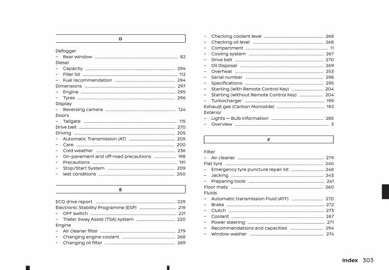
D
Defogger– Rear window ........................................................................................... 82Diesel– Capacity .................................................................................................. 294– Filler lid ....................................................................................................... 112– Fuel recommendation .................................................................. 294Dimensions ................................................................................................... 297– Engine ....................................................................................................... 295– Tyres ........................................................................................................... 296Display– Reversing camera ............................................................................. 124Doors– Tailgate ...................................................................................................... 115Drive belt ......................................................................................................... 270Driving .............................................................................................................. 205– Automatic Transmission (AT) .................................................. 205– Care ............................................................................................................ 200– Cold weather ....................................................................................... 236– On-pavement and off-road precautions ........................ 198– Precautions ............................................................................................ 191– Stop/Start System .......................................................................... 209– Wet conditions ................................................................................... 200
E
ECO drive report ....................................................................................... 229Electronic Stability Programme (ESP) ........................................ 219– OFF switch .............................................................................................. 221– Trailer Sway Assist (TSA) system .......................................... 220Engine– Air cleaner filter .................................................................................. 279– Changing engine coolant .......................................................... 268– Changing oil filter ............................................................................. 269
– Checking coolant level ................................................................. 268– Checking oil level ............................................................................. 268– Compartment .......................................................................................... 11– Cooling system .................................................................................. 267– Drive belt ................................................................................................. 270– Oil Disposal ........................................................................................... 269– Overheat ................................................................................................. 253– Serial number ..................................................................................... 298– Specifications ...................................................................................... 295– Starting (With Remote Control Key) .................................. 204– Starting (Without Remote Control Key) .......................... 204– Turbocharger ....................................................................................... 199Exhaust gas (Carbon Monoxide) .................................................... 192Exterior– Lights — Bulb information ......................................................... 285– Overview ....................................................................................................... 3
F
Filter– Air cleaner .............................................................................................. 279Flat tyre ........................................................................................................... 240– Emergency tyre puncture repair kit ................................... 246– Jacking ..................................................................................................... 243– Preparing tools ................................................................................... 241Floor mats ..................................................................................................... 260Fluids– Automatic transmission Fluid (ATF) ................................... 270– Brake .......................................................................................................... 272– Clutch ........................................................................................................ 273– Coolant ..................................................................................................... 267– Power steering .................................................................................... 271– Recommendations and capacities .................................... 294– Window washer ................................................................................. 274
Index 303
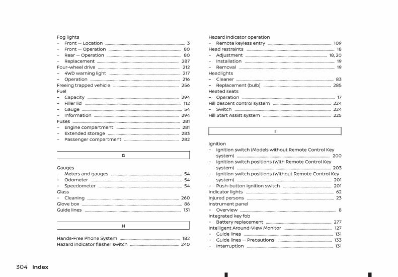
Fog lights– Front — Location ..................................................................................... 3– Front — Operation .............................................................................. 80– Rear — Operation ................................................................................ 80– Replacement ........................................................................................ 287Four-wheel drive ........................................................................................ 212– 4WD warning light ............................................................................ 217– Operation ................................................................................................ 216Freeing trapped vehicle ....................................................................... 256Fuel– Capacity .................................................................................................. 294– Filler lid ....................................................................................................... 112– Gauge ........................................................................................................... 54– Information ........................................................................................... 294Fuses ................................................................................................................... 281– Engine compartment .................................................................... 281– Extended storage ............................................................................ 283– Passenger compartment ........................................................... 282
G
Gauges– Meters and gauges ............................................................................ 54– Odometer ................................................................................................. 54– Speedometer ......................................................................................... 54Glass– Cleaning .................................................................................................. 260Glove box ........................................................................................................... 86Guide lines ....................................................................................................... 131
H
Hands-Free Phone System ................................................................ 182Hazard indicator flasher switch .................................................... 240
Hazard indicator operation– Remote keyless entry .................................................................... 109Head restraints .............................................................................................. 18– Adjustment ....................................................................................... 18, 20– Installation ................................................................................................ 19– Removal ...................................................................................................... 19Headlights– Cleaner ........................................................................................................ 83– Replacement (bulb) ........................................................................ 285Heated seats– Operation ................................................................................................... 17Hill descent control system .............................................................. 224– Switch ....................................................................................................... 224Hill Start Assist system ......................................................................... 225
I
Ignition– Ignition switch (Models without Remote Control Key
system) .................................................................................................... 200– Ignition switch positions (With Remote Control Key
system) .................................................................................................... 203– Ignition switch positions (Without Remote Control Key
system) ..................................................................................................... 201– Push-button ignition switch .................................................... 201Indicator lights .............................................................................................. 62Injured persons ............................................................................................. 23Instrument panel– Overview ....................................................................................................... 8Integrated key fob– Battery replacement ...................................................................... 277Intelligent Around-View Monitor ................................................... 127– Guide lines ............................................................................................... 131– Guide lines — Precautions .......................................................... 133– Interruption ............................................................................................ 131
304 Index
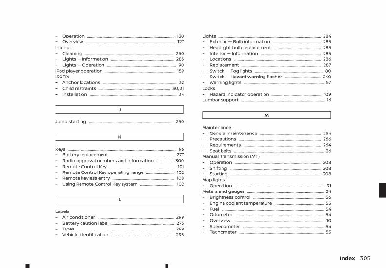
– Operation ................................................................................................ 130– Overview .................................................................................................. 127Interior– Cleaning .................................................................................................. 260– Lights — Information ..................................................................... 285– Lights — Operation ............................................................................ 90IPod player operation ............................................................................. 159ISOFIX– Anchor locations ................................................................................. 32– Child restraints ............................................................................... 30, 31– Installation ............................................................................................... 34
J
Jump starting ............................................................................................. 250
K
Keys ....................................................................................................................... 96– Battery replacement ...................................................................... 277– Radio approval numbers and information .................. 300– Remote Control Key ......................................................................... 101– Remote Control Key operating range ............................... 102– Remote keyless entry .................................................................... 108– Using Remote Control Key system ...................................... 102
L
Labels– Air conditioner .................................................................................... 299– Battery caution label ..................................................................... 275– Tyres ........................................................................................................... 299– Vehicle identification ..................................................................... 298
Lights ................................................................................................................. 284– Exterior — Bulb information ..................................................... 285– Headlight bulb replacement .................................................... 285– Interior — Information .................................................................. 285– Locations ................................................................................................ 286– Replacement ........................................................................................ 287– Switch — Fog lights ........................................................................... 80– Switch — Hazard warning flasher ....................................... 240– Warning lights ........................................................................................ 57Locks– Hazard indicator operation ....................................................... 109Lumbar support ............................................................................................ 16
M
Maintenance– General maintenance ................................................................... 264– Precautions .......................................................................................... 266– Requirements ..................................................................................... 264– Seat belts ................................................................................................... 26Manual Transmission (MT)– Operation .............................................................................................. 208– Shifting .................................................................................................... 208– Starting ................................................................................................... 208Map lights– Operation ................................................................................................... 91Meters and gauges .................................................................................... 54– Brightness control .............................................................................. 56– Engine coolant temperature ...................................................... 55– Fuel ................................................................................................................ 54– Odometer ................................................................................................. 54– Overview .................................................................................................... 10– Speedometer ......................................................................................... 54– Tachometer ............................................................................................. 55
Index 305
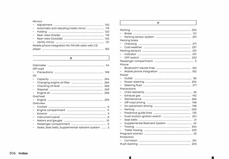
Mirrors– Adjustment ............................................................................................ 120– Automatic anti-dazzling inside mirror ............................... 119– Folding ...................................................................................................... 120– Rear-view (Inside) ............................................................................... 118– Rear-view (Outside) ......................................................................... 120– Vanity mirror .......................................................................................... 121Mobile phone integration for FM AM radio with CDplayer .................................................................................................................. 182
O
Odometer ......................................................................................................... 54Off-road– Precautions ........................................................................................... 198Oil– Capacity .................................................................................................. 294– Changing engine oil filter ........................................................... 269– Checking oil level ............................................................................. 268– Disposal ................................................................................................... 269– Engine oil ................................................................................................ 268Overheat– Engine ....................................................................................................... 253Overview– Cockpit ........................................................................................................... 6– Engine compartment ........................................................................ 11– Exterior .......................................................................................................... 3– Instrument panel ................................................................................... 8– Meters and gauges ............................................................................ 10– Passenger compartment ................................................................. 5– Seats, Seat belts, Supplemental restraint system ......... 2
P
Parking ............................................................................................................. 230– Brake ............................................................................................................ 121– Parking sensor system ................................................................. 231Parking brake– Checking .................................................................................................. 271– Cold weather ....................................................................................... 237Parking sensors .......................................................................................... 231– Indicator ................................................................................................... 231– OFF switch ............................................................................................. 232Passenger compartment ......................................................................... 5Phone– Bluetooth® Hands-Free ................................................................ 182– Mobile phone integration ........................................................... 182Power– Outlet ........................................................................................................... 85– Power steering ................................................................................... 234– Steering fluid ......................................................................................... 271Precautions– Child restraints ...................................................................................... 26– Exhaust gas ........................................................................................... 192– Maintenance ........................................................................................ 266– Off-road driving .................................................................................. 198– On-pavement driving .................................................................... 198– Parking ..................................................................................................... 230– Predictive guide lines ..................................................................... 133– Push-button ignition switch .................................................... 201– Seat belts .................................................................................................... 21– Supplemental Restraint System .............................................. 42– Towing ...................................................................................................... 254– Trailer towing ...................................................................................... 233Pregnant women ........................................................................................ 23Protection– Corrosion ................................................................................................. 261Push starting ............................................................................................... 253
306 Index
R
Radio– Approval numbers and information ................................. 300– FM AM DAB radio with CD (Type B) ...................................... 166– FM AM radio with CD (Type A) .................................................. 152– Touchscreen Navigation ............................................................. 180– Transmitter ........................................................................................... 299Rear window– Defogger .................................................................................................... 82Rear-view monitor– Settings ..................................................................................................... 127Rearview– Mirrors - Inside ..................................................................................... 118– Mirrors - Outside ............................................................................... 120Remote Control Key ................................................................................. 101– Battery - Discharge ........................................................................ 203– Operating range ................................................................................ 102– Operation ................................................................................................ 102– Push-button ignition switch .................................................... 201– Radio approval numbers and information .................. 300– Remote keyless entry .................................................................... 108– Starting engine ................................................................................. 204– System ...................................................................................................... 201– Troubleshooting guide ................................................................. 106– Warning signals .................................................................................. 104Remote keyless entry ............................................................................ 108Replacement– Air bags ....................................................................................................... 52– Air cleaner filter .................................................................................. 279– Battery (Key fob) ................................................................................ 277– Engine coolant ................................................................................... 268– Engine oil ................................................................................................ 269– Engine oil filter .................................................................................... 269– Fuses ........................................................................................................... 281– Lights ......................................................................................................... 287
– Wiper blades ........................................................................................ 280Reversing camera ..................................................................................... 124– Tips ............................................................................................................... 127Roof rails ............................................................................................................ 88Room light– Operation .................................................................................................. 92– Replacement ........................................................................................ 287Running-in schedule ............................................................................... 191
S
Safety– Head restraints ...................................................................................... 18Seat belts ............................................................................................................ 21– Adjustment .............................................................................................. 24– CENTER mark ......................................................................................... 23– Checking .................................................................................................... 25– Child safety .............................................................................................. 23– Children - Infants ................................................................................. 23– Children - Larger .................................................................................. 23– Children - Small .................................................................................... 23– Cleaning ................................................................................................... 261– Injured persons ..................................................................................... 23– Maintenance ........................................................................................... 26– Precautions ............................................................................................... 21– Pregnant women ................................................................................ 23– Three-point type ................................................................................. 24– Two-point type ..................................................................................... 25Seats ...................................................................................................................... 14– Adjustment (Manual) ......................................................................... 14– Adjustment (Power) ........................................................................... 15– Folding .......................................................................................................... 17– Front seats ................................................................................................ 14– Head restraints ...................................................................................... 18– ISOFIX child restraints .............................................................. 30, 31
Index 307
– Lumbar support .................................................................................... 16– Rear ................................................................................................................. 17– Universal child restraints (front and rear seats) ........... 27Security system ........................................................................................... 110Service– Maintenance ........................................................................................ 264Spare tyre ....................................................................................................... 242Speed limiter– Operation ............................................................................................... 228Speedometer ................................................................................................. 54Starting– Jump starting ..................................................................................... 250– Push starting ....................................................................................... 253– Without Remote Control Key .................................................. 204Steering– Power steering system ................................................................ 234– Steering wheel switches for phone control ................. 186Steering wheel ............................................................................................. 118– Adjustment ............................................................................................. 118– Switches — Audio control ........................................................... 180– Switches — Hands-free telephone control .................... 182Stop/Start System .................................................................................. 209– Display ....................................................................................................... 210– OFF switch ............................................................................................... 211Storage ............................................................................................................... 86– Card holder .............................................................................................. 88– Console box ............................................................................................ 86– Console side pockets ....................................................................... 87– Cup holders ............................................................................................. 87– Glove box ................................................................................................... 86– Roof rails .................................................................................................... 88– Sunglasses holder .............................................................................. 87Sun visors .......................................................................................................... 89– Card holder .............................................................................................. 88Sunroof ............................................................................................................... 89– Operation .................................................................................................. 89
Sunshade .......................................................................................................... 89Supplemental Restraint System (SRS) ........................................ 42– Overview ....................................................................................................... 2– Repair and replacement procedure ...................................... 52Switches– Defogger .................................................................................................... 82– Electronic Stability Programme (ESP) OFF switch .... 221– Fog lights .................................................................................................. 80– Hazard indicator flasher switch ........................................... 240– Headlight cleaner ................................................................................ 83– Hill descent control ......................................................................... 224– Ignition switch ................................................................................... 200– Parking sensor system ................................................................. 232– Seat adjustment ................................................................................... 15– Seat heating ............................................................................................. 17– Steering-wheel — Audio .............................................................. 180– Wiper and washer ................................................................................ 81
T
Tailgate ............................................................................................................... 115Theft warning system ............................................................................ 110Tools .................................................................................................................... 241Touchscreen Navigation ..................................................................... 180Towing– Precautions .......................................................................................... 254– Recommendations ......................................................................... 254– Recommended towing for four-wheel drive (4WD)
models ...................................................................................................... 255– Recommended towing for two-wheel drive (2WD)
models ...................................................................................................... 254– Trailer ......................................................................................................... 233– Your vehicle .......................................................................................... 254Trailer– Brakes ....................................................................................................... 234
308 Index
– Precautions ........................................................................................... 233– Safety chains ....................................................................................... 233– Towing ...................................................................................................... 233– Trailer detection ................................................................................ 234– Tyre pressure ....................................................................................... 233Trailer Sway Assist (TSA) system .................................................. 220Transferring registration to another country ..................... 298Transmission– Automatic transmission fluid (ATF) .................................... 270Transmitter– Radio .......................................................................................................... 299Travelling ........................................................................................................ 298Turbocharger ............................................................................................... 199Turn signal– Replacement ........................................................................................ 287Tyres– 4WD model ............................................................................................. 218– Age .............................................................................................................. 292– Cold weather ....................................................................................... 237– Flat tyre ................................................................................................... 240– Inflation pressure ............................................................................. 290– Placard ..................................................................................................... 299– Repairing flat tyre ............................................................................ 246– Rotation .................................................................................................... 291– Sizes ........................................................................................................... 296– Snow chains .......................................................................................... 291– Types ......................................................................................................... 290– Wear and damage ............................................................................ 291– Wheels and tyres .............................................................................. 290
U
Universal child restraints– Front and rear seats .......................................................................... 27
V
Vanity mirror– Lights ............................................................................................................ 92Variable voltage control system .................................................... 281Vehicle battery ........................................................................................... 275Vehicle identification ............................................................................. 298– Air conditioner label ....................................................................... 299– Engine serial number .................................................................... 298– Label .......................................................................................................... 298– Number (VIN) (chassis number) ............................................ 298– Number (VIN) plate ......................................................................... 298– Tyre placard .......................................................................................... 299Vehicle security .......................................................................................... 234– Theft warning system .................................................................... 110Vents ................................................................................................................... 136
W
Warning/indicator lights and audible reminders– Warning lights ........................................................................................ 57Wheels– Blocking ................................................................................................... 242– Cleaning .................................................................................................. 259– Installation ............................................................................................ 246– Removal .................................................................................................. 243– Sizes ........................................................................................................... 296– Stowing ................................................................................................... 246Window washer fluid .............................................................................. 274Windows– Defogger .................................................................................................... 82Windscreen– Wiper and washer switch .............................................................. 81Winter– Precautions ........................................................................................... 236
Index 309
– Special equipment ........................................................................... 237Wipers– Blades replacement ....................................................................... 280– Operation (Windscreen) .................................................................. 81– Washer nozzle ..................................................................................... 279– Window washer cleaner fluid .................................................. 274– Wiper and washer switch .............................................................. 81
310 Index
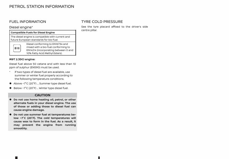
FUEL INFORMATIONDiesel engine*
Compatible Fuels for Diesel EngineThe diesel engine is compatible with current andfuture European standards for bio-fuel.
Diesel conforming to EN16734 andmixed with a bio-fuel conforming toEN14214 (incorporating between 0 and10% Fatty Acid Methyl Esters).
M9T 2.3DCI engine:
Diesel fuel above 50 cetane and with less than 10ppm of sulphur (EN590) must be used.
* If two types of diesel fuel are available, usesummer or winter fuel properly according tothe following temperature conditions.
• Above −7°C (20°F) ... Summer type diesel fuel.
• Below −7°C (20°F) ... Winter type diesel fuel.
CAUTION• Do not use home heating oil, petrol, or other
alternate fuels in your diesel engine. The useof those or adding those to diesel fuel cancause engine damage.
• Do not use summer fuel at temperatures be-low −7°C (20°F). The cold temperatures willcause wax to form in the fuel. As a result, itmay prevent the engine from runningsmoothly.
TYRE COLD PRESSURESee the tyre placard affixed to the driver’s sidecentre pillar.
PETROL STATION INFORMATION
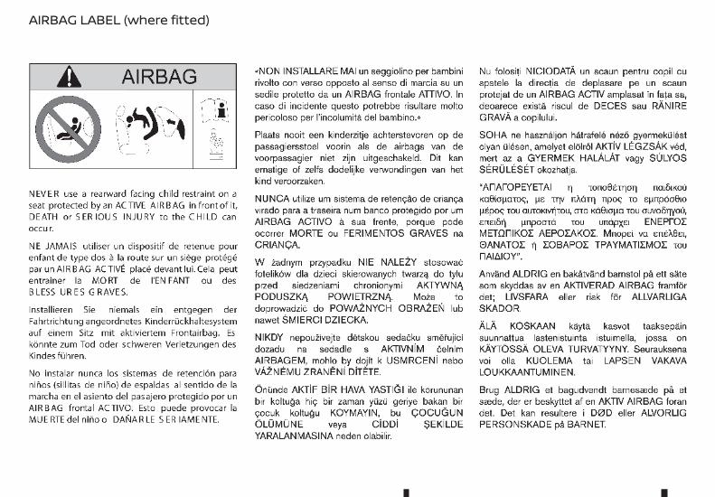
AIRBAG LABEL (where fitted)
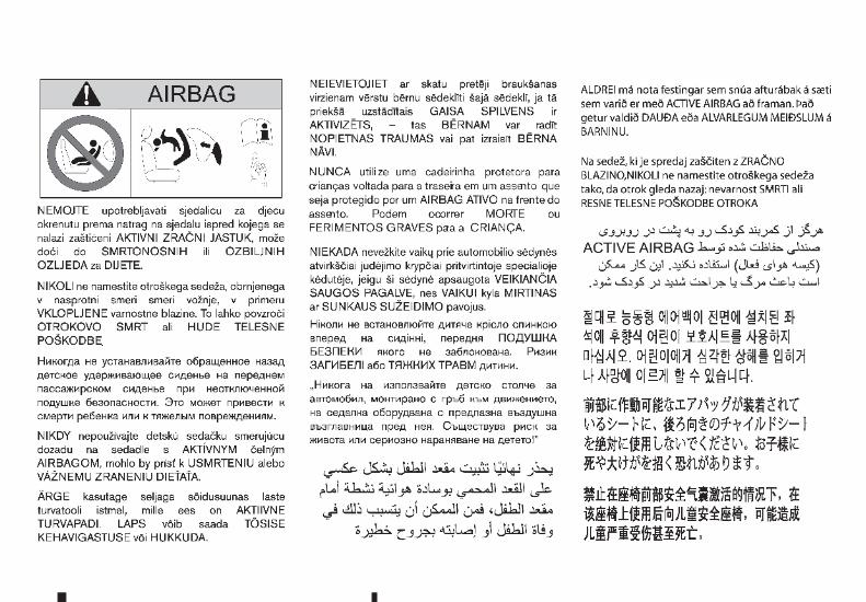

• In case of emergency ... 6-240
(Flat tyre, engine will not start, overheating,towing)
• How to start the engine ... 5-191
• How to read the meters and gauges ... 2-191
• Maintenance and do-it-yourself ... 8-264
• Technical information ... 9-294
QUICK REFERENCE

VIN:..........................................................................................................................................
Date: Km (Miles): Invoice number: Comments/miscellaneousType of operation: StampService
............................................................Anti-corrosion check: OK Not OK*
*See specific pageDate: Km (Miles): Invoice number: Comments/miscellaneousType of operation: StampService
............................................................Anti-corrosion check: OK Not OK*
*See specific pageDate: Km (Miles): Invoice number: Comments/miscellaneousType of operation: StampService
............................................................Anti-corrosion check: OK Not OK*
*See specific page
SERVICE SHEETS (1/6)

VIN:..........................................................................................................................................
Date: Km (Miles): Invoice number: Comments/miscellaneousType of operation: StampService
............................................................Anti-corrosion check: OK Not OK*
*See specific pageDate: Km (Miles): Invoice number: Comments/miscellaneousType of operation: StampService
............................................................Anti-corrosion check: OK Not OK*
*See specific pageDate: Km (Miles): Invoice number: Comments/miscellaneousType of operation: StampService
............................................................Anti-corrosion check: OK Not OK*
*See specific page
SERVICE SHEETS (2/6)

VIN:..........................................................................................................................................
Date: Km (Miles): Invoice number: Comments/miscellaneousType of operation: StampService
............................................................Anti-corrosion check: OK Not OK*
*See specific pageDate: Km (Miles): Invoice number: Comments/miscellaneousType of operation: StampService
............................................................Anti-corrosion check: OK Not OK*
*See specific pageDate: Km (Miles): Invoice number: Comments/miscellaneousType of operation: StampService
............................................................Anti-corrosion check: OK Not OK*
*See specific page
SERVICE SHEETS (3/6)
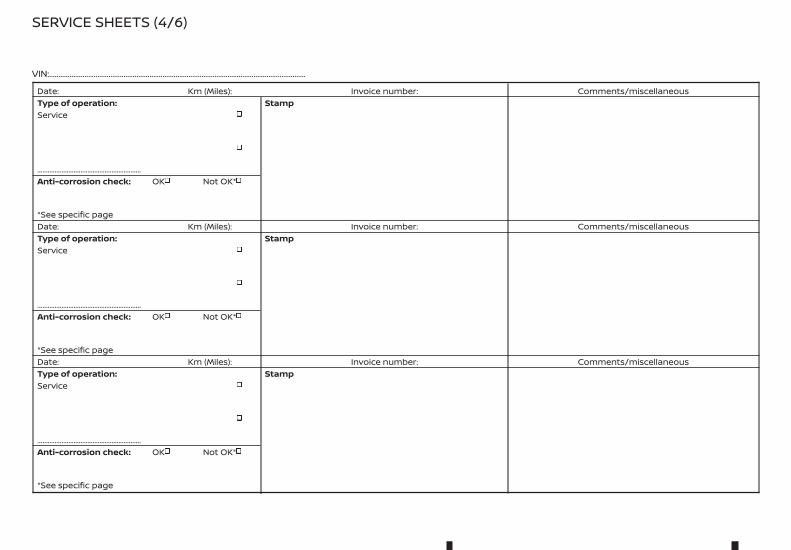
VIN:..........................................................................................................................................
Date: Km (Miles): Invoice number: Comments/miscellaneousType of operation: StampService
............................................................Anti-corrosion check: OK Not OK*
*See specific pageDate: Km (Miles): Invoice number: Comments/miscellaneousType of operation: StampService
............................................................Anti-corrosion check: OK Not OK*
*See specific pageDate: Km (Miles): Invoice number: Comments/miscellaneousType of operation: StampService
............................................................Anti-corrosion check: OK Not OK*
*See specific page
SERVICE SHEETS (4/6)
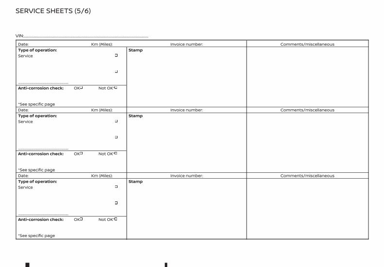
VIN:..........................................................................................................................................
Date: Km (Miles): Invoice number: Comments/miscellaneousType of operation: StampService
............................................................Anti-corrosion check: OK Not OK*
*See specific pageDate: Km (Miles): Invoice number: Comments/miscellaneousType of operation: StampService
............................................................Anti-corrosion check: OK Not OK*
*See specific pageDate: Km (Miles): Invoice number: Comments/miscellaneousType of operation: StampService
............................................................Anti-corrosion check: OK Not OK*
*See specific page
SERVICE SHEETS (5/6)

VIN:..........................................................................................................................................
Date: Km (Miles): Invoice number: Comments/miscellaneousType of operation: StampService
............................................................Anti-corrosion check: OK Not OK*
*See specific pageDate: Km (Miles): Invoice number: Comments/miscellaneousType of operation: StampService
............................................................Anti-corrosion check: OK Not OK*
*See specific pageDate: Km (Miles): Invoice number: Comments/miscellaneousType of operation: StampService
............................................................Anti-corrosion check: OK Not OK*
*See specific page
SERVICE SHEETS (6/6)

If the continuation of the warranty is subject to repair, it is indicated below.
VIN:......................................................................................................
Corrosion repair operation to be carried out: Stamp
Date of repair:
Repair to be carried out: Stamp
Date of repair:
Repair to be carried out: Stamp
Date of repair:
ANTICORROSION CHECK (1/6)
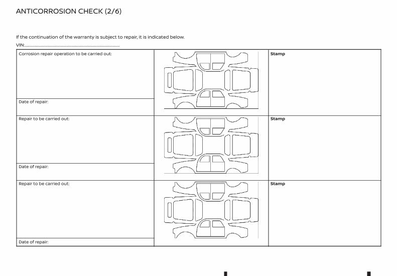
If the continuation of the warranty is subject to repair, it is indicated below.
VIN:......................................................................................................
Corrosion repair operation to be carried out: Stamp
Date of repair:
Repair to be carried out: Stamp
Date of repair:
Repair to be carried out: Stamp
Date of repair:
ANTICORROSION CHECK (2/6)

If the continuation of the warranty is subject to repair, it is indicated below.
VIN:......................................................................................................
Corrosion repair operation to be carried out: Stamp
Date of repair:
Repair to be carried out: Stamp
Date of repair:
Repair to be carried out: Stamp
Date of repair:
ANTICORROSION CHECK (3/6)

If the continuation of the warranty is subject to repair, it is indicated below.
VIN:......................................................................................................
Corrosion repair operation to be carried out: Stamp
Date of repair:
Repair to be carried out: Stamp
Date of repair:
Repair to be carried out: Stamp
Date of repair:
ANTICORROSION CHECK (4/6)
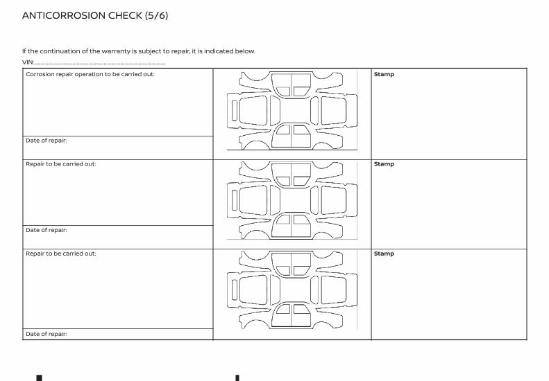
If the continuation of the warranty is subject to repair, it is indicated below.
VIN:......................................................................................................
Corrosion repair operation to be carried out: Stamp
Date of repair:
Repair to be carried out: Stamp
Date of repair:
Repair to be carried out: Stamp
Date of repair:
ANTICORROSION CHECK (5/6)

If the continuation of the warranty is subject to repair, it is indicated below.
VIN:......................................................................................................
Corrosion repair operation to be carried out: Stamp
Date of repair:
Repair to be carried out: Stamp
Date of repair:
Repair to be carried out: Stamp
Date of repair:
ANTICORROSION CHECK (6/6)
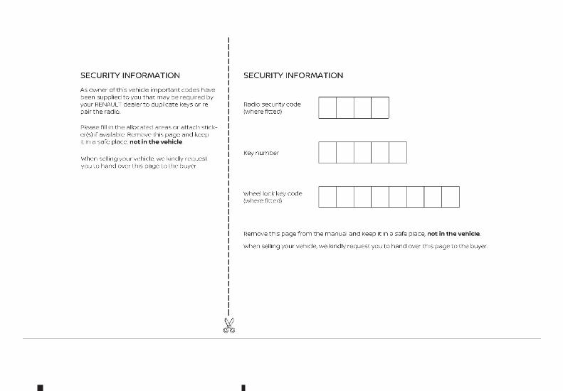


Castrol, exclusive Renault partner
Renault recommends
Castrol, exclusive Renault partner
Benefit from cutting-edge technology born out of competition to ensure the performance and longevity ofyour Renault thanks to wide range of engine lubricants developed specially by Renault and Castrol.
Renault recommends
renault.com
U60
EN
U60
EN
Renault ALASKANVehicle user manual
RENAULT S.A.S. SOCIÉTÉ PAR ACTIONS SIMPLIFIÉE AU CAPITAL DE 533 941 113 € - 13-15, QUAI LE GALLO
92100 BOULOGNE-BILLANCOURT R.C.S. NANTERRE 780 129 987 — SIRET 780 129 987 03591 - TÉL. : 0810 40 50 60
Printing: November 2020 (01) / Publication Number: OM20EN-0U60E1EUR / Part Number: 7711413295--- / Printed in France
U60
EN
Related Documents