12/22/2017 Direct-Hit -- Search http://dh.identifix.com/SearchFixes/Index?ROID=182881898&VID=2419299&VSM=1&LocationId=2#KW=Crankshaft+Pulley&SOption=1&VETId=8&S… 1/24 REMOVAL AND INSTALLATION: CRA... REMOVAL AND INSTALLATION: TIMING BELT (ENGINE - 1.6L ECOBOOST (132KW/180PS) - SIGMA) 303-01A Engine - 1.6L EcoBoost (132kW/180PS) - Sigma 2015 Escape Removal and Installation Procedure revision date: 04/24/2015 Timing Belt Special Tool(s) / General Equipment 303-050 (T70P-6000) Lifting Bracket, Engine 303-1097 Locking Tool, Variable Camshaft Timing Oil Control Unit TKIT-2010B-FLM TKIT-2010B-ROW 303-1502 Lifting Device Engine TKIT-2012A-FL TKIT-2012A-ROW 303-1550 Alignment Tool, Crankshaft Vibration Damper TKIT-2012A-FL TKIT-2012A-ROW 303-290B-18 Adapter for 303-290B TKIT-2012A-FL TKIT-2012A-ROW 303-393-02 Adapter for 303-393 TKIT-2012A-FL TKIT-2012A-ROW 303-393A Locking Tool, Flywheel TKIT-2012A-FL TKIT-2012A-ROW 303-748 Locking Tool, Crankshaft TKIT-2010B-FLM TKIT-2010B-ROW 303-F072 Support Bar, Engine Trolley Jack Wooden Block

Welcome message from author
This document is posted to help you gain knowledge. Please leave a comment to let me know what you think about it! Share it to your friends and learn new things together.
Transcript
12/22/2017 Direct-Hit -- Search
http://dh.identifix.com/SearchFixes/Index?ROID=182881898&VID=2419299&VSM=1&LocationId=2#KW=Crankshaft+Pulley&SOption=1&VETId=8&S… 1/24
REMOVAL AND INSTALLATION: CRA...
REMOVAL AND INSTALLATION: TIMING BELT (ENGINE - 1.6L ECOBOOST (132KW/180PS) - SIGMA)303-01A Engine - 1.6L EcoBoost (132kW/180PS) - Sigma 2015 EscapeRemoval and Installation Procedure revision date: 04/24/2015
Timing Belt
Special Tool(s) / General Equipment
303-050 (T70P-6000) Lifting Bracket, Engine
303-1097 Locking Tool, Variable Camshaft Timing Oil Control Unit TKIT-2010B-FLM TKIT-2010B-ROW
303-1502 Lifting Device Engine TKIT-2012A-FL TKIT-2012A-ROW
303-1550 Alignment Tool, Crankshaft Vibration Damper TKIT-2012A-FL TKIT-2012A-ROW
303-290B-18 Adapter for 303-290B TKIT-2012A-FL TKIT-2012A-ROW
303-393-02 Adapter for 303-393 TKIT-2012A-FL TKIT-2012A-ROW
303-393A Locking Tool, Flywheel TKIT-2012A-FL TKIT-2012A-ROW
303-748 Locking Tool, Crankshaft TKIT-2010B-FLM TKIT-2010B-ROW
303-F072 Support Bar, Engine
Trolley JackWooden Block

12/22/2017 Direct-Hit -- Search
http://dh.identifix.com/SearchFixes/Index?ROID=182881898&VID=2419299&VSM=1&LocationId=2#KW=Crankshaft+Pulley&SOption=1&VETId=8&S… 2/24
Removal
NOTE:Do not loosen or remove the crankshaft pulley bolt without first installing the special tools. The crankshaft pulley and thecrankshaft timing sprocket are not keyed to the crankshaft. Before any repair requiring loosening or removal of the crankshaft pulleybolt, the crankshaft and camshafts must be locked in place by the special service tools, otherwise severe engine damage can occur.
NOTE:During engine repair procedures, cleanliness is extremely important. Any foreign material, including any material created whilecleaning gasket surfaces, that enters the oil passages, coolant passages or the oil pan can cause engine failure.
1. Refer to: Jacking and Lifting - Overview (100-02 Jacking and Lifting, Description and Operation) .
2. Refer to: Cowl Panel (501-02 Front End Body Panels, Removal and Installation) .
3.
4.
5. Remove the following items:1. Refer to: Degas Bottle (303-03A Engine Cooling - 1.6L EcoBoost (132kW/180PS) - Sigma, Removal and Installation) . 2. Remove the RH front wheel and tire.
Refer to: Wheel and Tire (204-04A Wheels and Tires, Removal and Installation) .
6.

12/22/2017 Direct-Hit -- Search
http://dh.identifix.com/SearchFixes/Index?ROID=182881898&VID=2419299&VSM=1&LocationId=2#KW=Crankshaft+Pulley&SOption=1&VETId=8&S… 3/24
7. Remove the RH front fender splash shield. Refer to: Fender Splash Shield (501-02 Front End Body Panels, Removal and Installation) .
8.
9. Remove the following items:1. Refer to: Starter Motor (303-06A Starting System - 1.6L EcoBoost (132kW/180PS) - Sigma, Removal and Installation) . 2. Refer to: Generator - 1.6L EcoBoost (132kW/180PS) - Sigma (414-02 Generator and Regulator, Removal and Installation) .
10.
11.
12/22/2017 Direct-Hit -- Search
http://dh.identifix.com/SearchFixes/Index?ROID=182881898&VID=2419299&VSM=1&LocationId=2#KW=Crankshaft+Pulley&SOption=1&VETId=8&S… 4/24
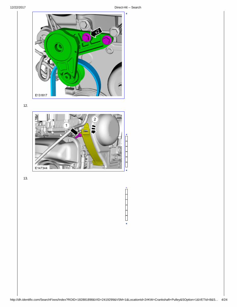
12.
13.

12/22/2017 Direct-Hit -- Search
http://dh.identifix.com/SearchFixes/Index?ROID=182881898&VID=2419299&VSM=1&LocationId=2#KW=Crankshaft+Pulley&SOption=1&VETId=8&S… 5/24
14.
15. Install Special Service Tool: 303-1502 Lifting Device Engine .

12/22/2017 Direct-Hit -- Search
http://dh.identifix.com/SearchFixes/Index?ROID=182881898&VID=2419299&VSM=1&LocationId=2#KW=Crankshaft+Pulley&SOption=1&VETId=8&S… 6/24
16. Install Special Service Tool: 303-050 (T70P-6000) Lifting Bracket, Engine .
17. Install Special Service Tool: 303-F072 Support Bar, Engine . , 303-290B-18 Adapter for 303-290B .
18. Remove the following items:Use the General Equipment: Trolley Jack Use the General Equipment: Wooden Block

12/22/2017 Direct-Hit -- Search
http://dh.identifix.com/SearchFixes/Index?ROID=182881898&VID=2419299&VSM=1&LocationId=2#KW=Crankshaft+Pulley&SOption=1&VETId=8&S… 7/24
19. NOTICE: Only rotate the crankshaft in a clockwise direction.
11 o'clock position.
20.
12/22/2017 Direct-Hit -- Search
http://dh.identifix.com/SearchFixes/Index?ROID=182881898&VID=2419299&VSM=1&LocationId=2#KW=Crankshaft+Pulley&SOption=1&VETId=8&S… 8/24
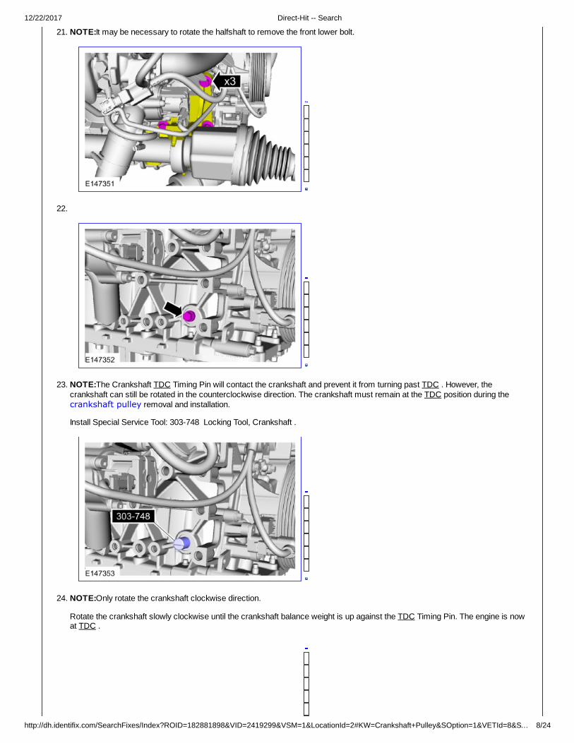
21. NOTE:It may be necessary to rotate the halfshaft to remove the front lower bolt.
22.
23. NOTE:The Crankshaft TDC Timing Pin will contact the crankshaft and prevent it from turning past TDC . However, thecrankshaft can still be rotated in the counterclockwise direction. The crankshaft must remain at the TDC position during thecrankshaft pulley removal and installation.
Install Special Service Tool: 303-748 Locking Tool, Crankshaft .
24. NOTE:Only rotate the crankshaft clockwise direction.
Rotate the crankshaft slowly clockwise until the crankshaft balance weight is up against the TDC Timing Pin. The engine is nowat TDC .
12/22/2017 Direct-Hit -- Search
http://dh.identifix.com/SearchFixes/Index?ROID=182881898&VID=2419299&VSM=1&LocationId=2#KW=Crankshaft+Pulley&SOption=1&VETId=8&S… 9/24
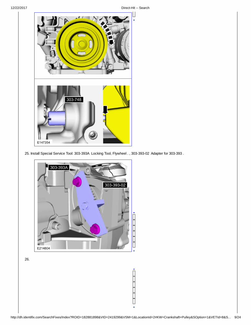
25. Install Special Service Tool: 303-393A Locking Tool, Flywheel . , 303-393-02 Adapter for 303-393 .
26.

12/22/2017 Direct-Hit -- Search
http://dh.identifix.com/SearchFixes/Index?ROID=182881898&VID=2419299&VSM=1&LocationId=2#KW=Crankshaft+Pulley&SOption=1&VETId=8&… 10/24
27. NOTE:The timing mark of each VCT unit must be at the 12 o'clock position.
NOTE:It may necessary to rotate the camshafts slightly to install the special tool.
Install Special Service Tool: 303-1097 Locking Tool, Variable Camshaft Timing Oil Control Unit .
28. WARNING: The timing belt tensioner spring is under load. Extra care must be taken at all times when handling thetensioner. Failure to follow this instruction may result in personal injury.
NOTE:Install a holding pin.

12/22/2017 Direct-Hit -- Search
http://dh.identifix.com/SearchFixes/Index?ROID=182881898&VID=2419299&VSM=1&LocationId=2#KW=Crankshaft+Pulley&SOption=1&VETId=8&… 11/24
29.
30.
Installation
1. NOTE:Before installation, clean and inspect the sprocket for any damage. If damage is evident, replace the sprocket. If nodamage, the sprocket is to be reused.

12/22/2017 Direct-Hit -- Search
http://dh.identifix.com/SearchFixes/Index?ROID=182881898&VID=2419299&VSM=1&LocationId=2#KW=Crankshaft+Pulley&SOption=1&VETId=8&… 12/24
2.
3. WARNING: The timing belt tensioner spring is under load. Extra care must be taken at all times when handling thetensioner. Failure to follow this instruction may result in personal injury.
Remove the holding pin.

12/22/2017 Direct-Hit -- Search
http://dh.identifix.com/SearchFixes/Index?ROID=182881898&VID=2419299&VSM=1&LocationId=2#KW=Crankshaft+Pulley&SOption=1&VETId=8&… 13/24
4.
5. 1. Install Special Service Tool: 303-1550 Alignment Tool, Crankshaft Vibration Damper .2. Rotate crankshaft pulley to align the Special Tool:
Use Special Service Tool: 303-1550 Alignment Tool, Crankshaft Vibration Damper .3. Finger tight at this stage. 4. Using a new bolt, finger tight at this stage.

12/22/2017 Direct-Hit -- Search
http://dh.identifix.com/SearchFixes/Index?ROID=182881898&VID=2419299&VSM=1&LocationId=2#KW=Crankshaft+Pulley&SOption=1&VETId=8&… 14/24
6. Remove Special Service Tool: 303-1550 Alignment Tool, Crankshaft Vibration Damper .
7. Torque : Stage 1: 74 lb.ft (100 Nm) Stage 2: 90° Stage 3: Wait 2s Stage 4: 15°
8. Remove Special Service Tool: 303-748 Locking Tool, Crankshaft .
9. Remove Special Service Tool: 303-393-02 Adapter for 303-393 . , 303-393A Locking Tool, Flywheel .

12/22/2017 Direct-Hit -- Search
http://dh.identifix.com/SearchFixes/Index?ROID=182881898&VID=2419299&VSM=1&LocationId=2#KW=Crankshaft+Pulley&SOption=1&VETId=8&… 15/24
10. Remove Special Service Tool: 303-1097 Locking Tool, Variable Camshaft Timing Oil Control Unit .
11. NOTE:Only rotate the crankshaft in a clockwise direction.
Rotate about 1 3/4 turns.
12. Install Special Service Tool: 303-748 Locking Tool, Crankshaft .

12/22/2017 Direct-Hit -- Search
http://dh.identifix.com/SearchFixes/Index?ROID=182881898&VID=2419299&VSM=1&LocationId=2#KW=Crankshaft+Pulley&SOption=1&VETId=8&… 16/24
13. NOTE:Only rotate the crankshaft in a clockwise direction.
Rotate the crankshaft slowly clockwise until the crankshaft balance weight is up against the crankshaft locking tool. The engine isnow at TDC .
14. NOTE:The timing mark of each VCT unit must be at the 12 o'clock position.
NOTE:It may necessary to rotate the camshafts slightly to install the special tool.
If the special tool cannot be installed, repeat the adjustment according to the preceding steps. Install Special Service Tool: 303-1097 Locking Tool, Variable Camshaft Timing Oil Control Unit .

12/22/2017 Direct-Hit -- Search
http://dh.identifix.com/SearchFixes/Index?ROID=182881898&VID=2419299&VSM=1&LocationId=2#KW=Crankshaft+Pulley&SOption=1&VETId=8&… 17/24
15. Remove Special Service Tool: 303-1097 Locking Tool, Variable Camshaft Timing Oil Control Unit .
16. Remove Special Service Tool: 303-748 Locking Tool, Crankshaft .
17. Torque : 177 lb.in (20 Nm)
12/22/2017 Direct-Hit -- Search
http://dh.identifix.com/SearchFixes/Index?ROID=182881898&VID=2419299&VSM=1&LocationId=2#KW=Crankshaft+Pulley&SOption=1&VETId=8&… 18/24
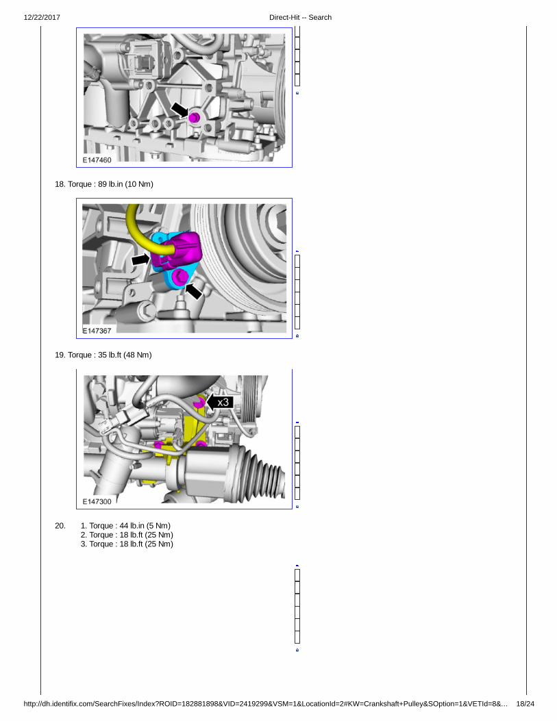
18. Torque : 89 lb.in (10 Nm)
19. Torque : 35 lb.ft (48 Nm)
20. 1. Torque : 44 lb.in (5 Nm)2. Torque : 18 lb.ft (25 Nm)3. Torque : 18 lb.ft (25 Nm)

12/22/2017 Direct-Hit -- Search
http://dh.identifix.com/SearchFixes/Index?ROID=182881898&VID=2419299&VSM=1&LocationId=2#KW=Crankshaft+Pulley&SOption=1&VETId=8&… 19/24
21. Install the following items:Use the General Equipment: Trolley Jack Use the General Equipment: Wooden Block
22. Remove Special Service Tool: 303-F072 Support Bar, Engine . , 303-290B-18 Adapter for 303-290B . , 303-050 (T70P-6000) Lifting Bracket, Engine .
23. Torque : 41 lb.ft (55 Nm)

12/22/2017 Direct-Hit -- Search
http://dh.identifix.com/SearchFixes/Index?ROID=182881898&VID=2419299&VSM=1&LocationId=2#KW=Crankshaft+Pulley&SOption=1&VETId=8&… 20/24
24. 1. Torque : 89 lb.in (10 Nm)2. Finger tight. 3. Finger tight.
25. Torque : 89 lb.in (10 Nm)
12/22/2017 Direct-Hit -- Search
http://dh.identifix.com/SearchFixes/Index?ROID=182881898&VID=2419299&VSM=1&LocationId=2#KW=Crankshaft+Pulley&SOption=1&VETId=8&… 21/24
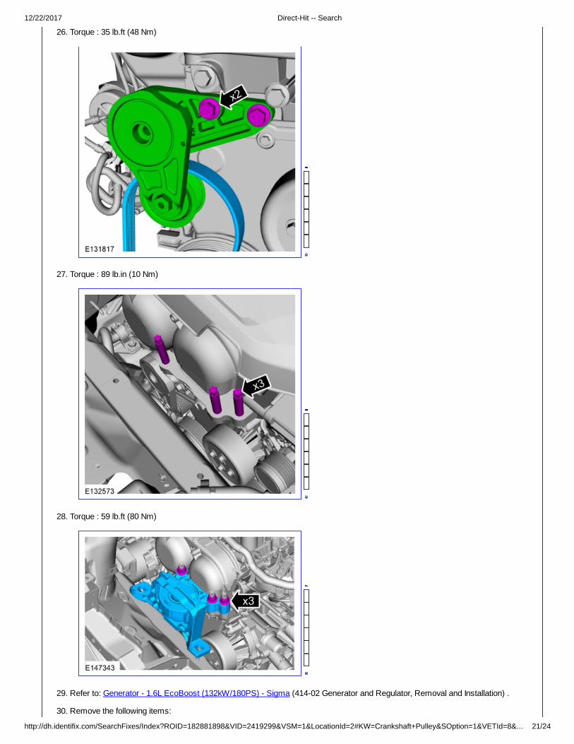
26. Torque : 35 lb.ft (48 Nm)
27. Torque : 89 lb.in (10 Nm)
28. Torque : 59 lb.ft (80 Nm)
29. Refer to: Generator - 1.6L EcoBoost (132kW/180PS) - Sigma (414-02 Generator and Regulator, Removal and Installation) .
30. Remove the following items:
12/22/2017 Direct-Hit -- Search
http://dh.identifix.com/SearchFixes/Index?ROID=182881898&VID=2419299&VSM=1&LocationId=2#KW=Crankshaft+Pulley&SOption=1&VETId=8&… 22/24
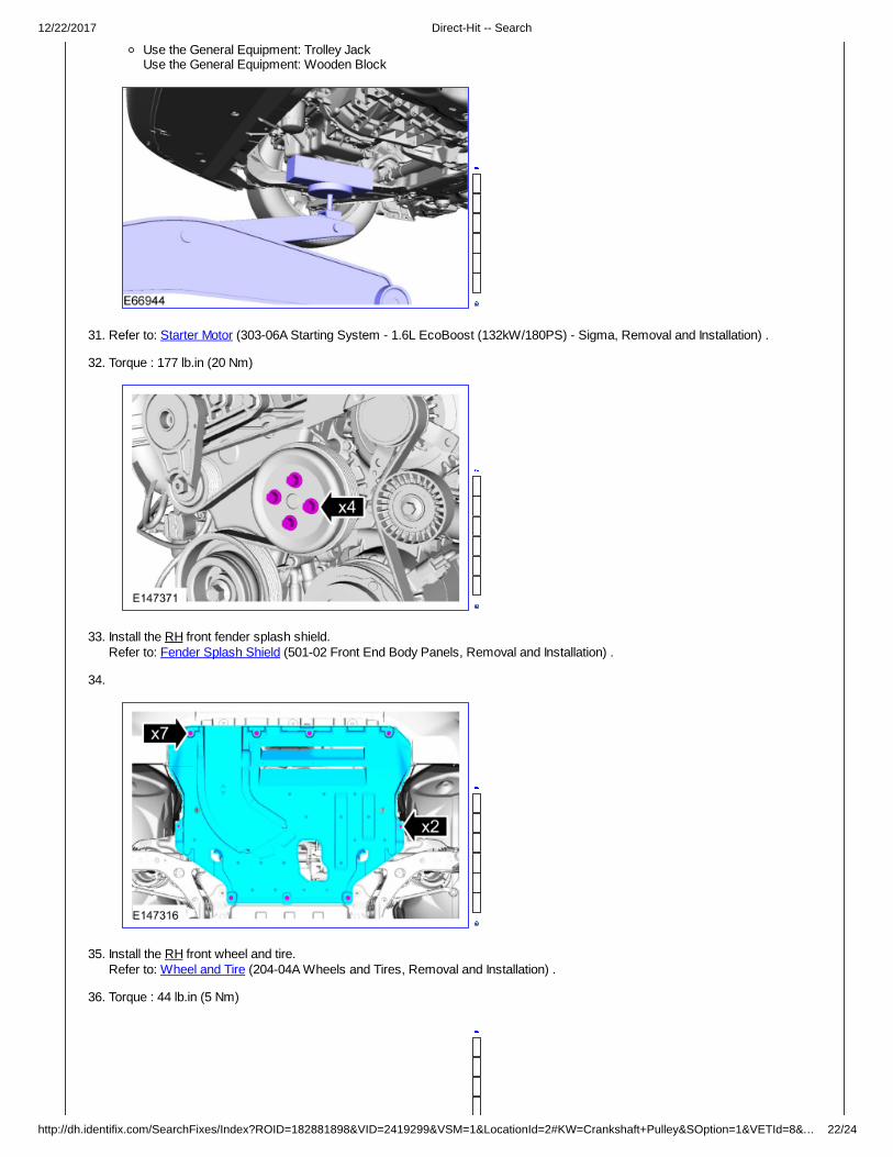
Use the General Equipment: Trolley Jack Use the General Equipment: Wooden Block
31. Refer to: Starter Motor (303-06A Starting System - 1.6L EcoBoost (132kW/180PS) - Sigma, Removal and Installation) .
32. Torque : 177 lb.in (20 Nm)
33. Install the RH front fender splash shield. Refer to: Fender Splash Shield (501-02 Front End Body Panels, Removal and Installation) .
34.
35. Install the RH front wheel and tire. Refer to: Wheel and Tire (204-04A Wheels and Tires, Removal and Installation) .
36. Torque : 44 lb.in (5 Nm)
12/22/2017 Direct-Hit -- Search
http://dh.identifix.com/SearchFixes/Index?ROID=182881898&VID=2419299&VSM=1&LocationId=2#KW=Crankshaft+Pulley&SOption=1&VETId=8&… 23/24
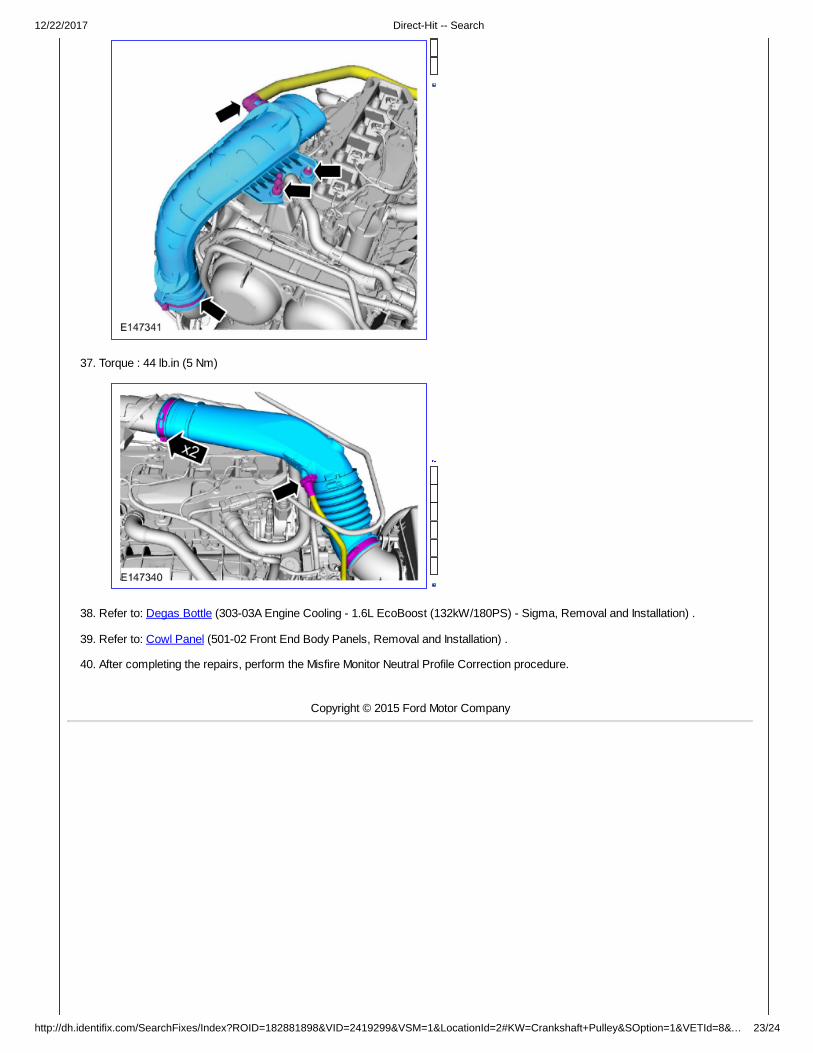
37. Torque : 44 lb.in (5 Nm)
38. Refer to: Degas Bottle (303-03A Engine Cooling - 1.6L EcoBoost (132kW/180PS) - Sigma, Removal and Installation) .
39. Refer to: Cowl Panel (501-02 Front End Body Panels, Removal and Installation) .
40. After completing the repairs, perform the Misfire Monitor Neutral Profile Correction procedure.
Copyright © 2015 Ford Motor Company

12/22/2017 Direct-Hit -- Search
http://dh.identifix.com/SearchFixes/Index?ROID=182881898&VID=2419299&VSM=1&LocationId=2#KW=Crankshaft+Pulley&SOption=1&VETId=8&… 24/24
This publication contains material that is reproduced and distributed under a license from Ford Motor Company. No further reproductionor distribution of the Ford Motor Company material is allowed without the express written permission of Ford Motor Company.
Copyright 2007 - 2015 Service Repair Solutions, Inc.
Related Documents