SMS/REMOTE CONTROL BASED HOME AUTOMATION BYNA RAVITEJA RAJA 10EC32 GOTHI SHAILESH 10EC46 MADAN MOHAN MISHRA 10EC58

remote/sms based home automation
Oct 29, 2014
a ppt on how to make remote/sms based home automation
Welcome message from author
This document is posted to help you gain knowledge. Please leave a comment to let me know what you think about it! Share it to your friends and learn new things together.
Transcript

SMS/REMOTE CONTROL BASED HOME AUTOMATION
BYNA RAVITEJA RAJA 10EC32 GOTHI SHAILESH 10EC46 MADAN MOHAN MISHRA 10EC58

Introduction With the advancement and breakthroughs in technology over the
years, the lives of people have become more complicated and thus they have become busier than before.
The comfort of being able to take control of devices from one particular location has become imperative as it saves a lot of time and effort.
With the adoption of our system, we can gain control over certain things like home appliances that required constant attention based on a REMOTE CONTROL or SMS (Short Message Service) mobile cell module .
Objective Remote Control based Home Automation At home as we control our TV, we can control other home appliances
like fan, tube light, etc. on a press of a button on remote control.
SMS based Home Automation When people who forget to do simple things such as turn ON or OFF
devices at their home or in their office, they can now do so without their presence by the transmission of a simple text message from their mobile phone.
This development, we believe, will ultimately save a lot of time especially when people don’t have to come back for simple things such as to turn ON/OFF switches at their home or at their office once they set out for their respective work.

Block Diagram

REMOTE CONTROL BASED
HOME AUTOMATION
Important AspectsRC-5 PROTOCOLTSOP 1738RECEIVER CIRCUITMICROCONTROLLERRELAY

RC-5 PROTOCOL A common used standard protocol
for infrared data communication is the RC5 code, originally developed by Philips.
The transmitted code is a data word which consists of 14 bits and is defined as:
2 start bits--for the automatic gain control in the infrared receiver.
1 toggle bit--change every time when a new button is pressed on the IR transmitter .
5 address bits-- for the system address.
6 instruction bits --for the pressed key .
The next challenge was to get something which would detect these codes so that microcontroller would read these codes. The solution is TSOP 1738.

TSOP 1736 TSOP 17XX is the standard IR remote control
receiver series, supporting all major transmission codes.
Here XX refers to the frequency of the infrared carrier signal on which the code is modulated, which is 36 KHz in our case.
It has three pins .
GND and Vcc are connected to the power supply with VCC as 5V and Vout which becomes 0V, or GND when the demodulated bit received is high i.e. 5V and vice versa.
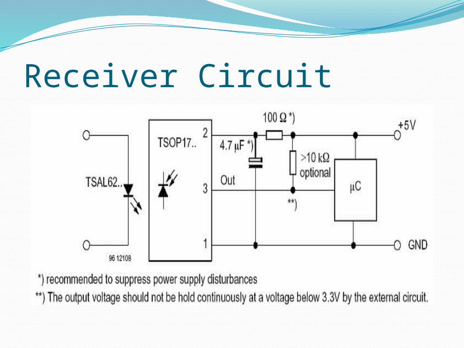
Receiver Circuit

Relay It basically is a switching device.
On providing a definite specified DC voltage across the induction coil, it gets magnetized and causes the switch (the middle one) to flip its position from where it was previously to the other pin, causing the device attached across it to turn on.
But we had a problem, we were provided with only 12 volt relay (it operated on 12 V) and the microcontroller gave 5V.
So we used a BJT transistor in Common emitter mode to amplify 5V to 12 V.
We finally attached our device across the relay to get it working when the relay received 12 V, otherwise not.

Problem Faced Which protocol my remote used
Timer: counting the pulse High and Low time
SMS BASED
HOME AUTOMATION

ComponentsGSM ModemMicrocontroller- ArduinoMAX232 ICRELAYBULB

GSM ModemMaestro 20 is a GSM
Modem supported with SMS, voice and fax services.
AT Commands based.
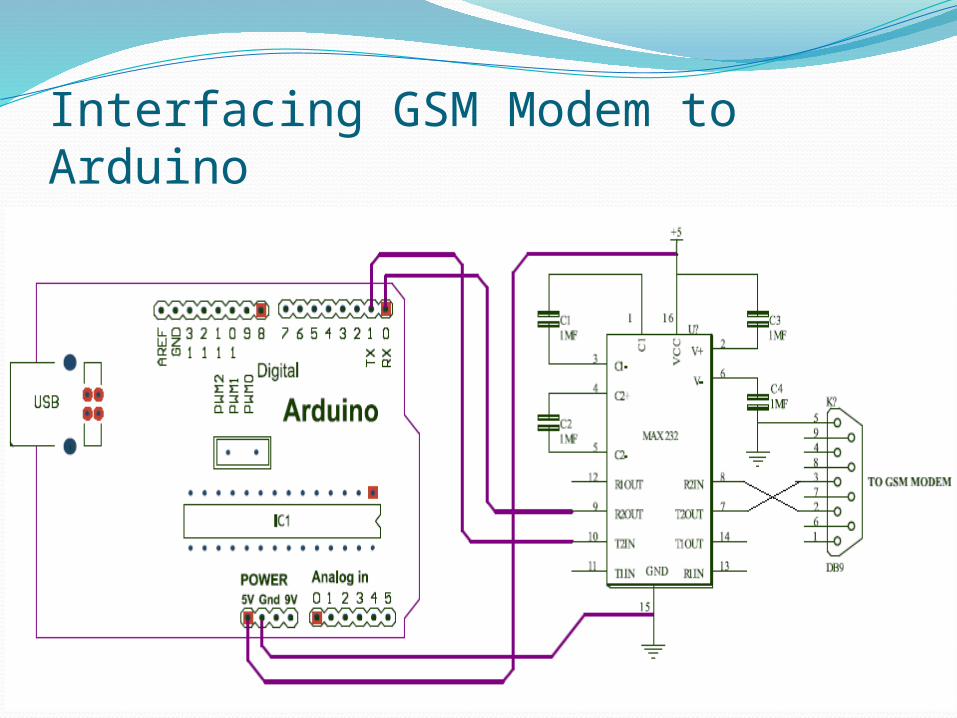
Interfacing GSM Modem to Arduino

AT Commands

To Read a SMS Initially set GSM to Text Mode by following Command: AT+CMGF=1 When the GSM receives a SMS message, the following message will appear on the
Serial Monitor of Arduino: +CMTI: “SM”, 1 To read the SMS : AT+CMGR=1 Response is:
In Text Mode: +CMGR: “REC READ”,”+918123872292”,”06/11/12,01:16:11+22” dev1 OK
In PDU Mode: +CMGR: 0,,24 07911614786007F0040B911604994743F400009930139100406B05E8329BFD06 OK

Problems Faced Switching from Mobile Phone to GSM Modem: Initially we had problems connecting the mobile phone with
microcontroller. Since we didn’t have F-Bus cable(out of stock in market) and connection without F-bus cable was very difficult.
Pin Connection Problems: Two types of DB9 Pins: DTE and DCE. Both had different Rx and Tx connections.

Conclusion The project we have undertaken has helped us gain a better
perspective on various aspects related to our course of study as well as practical knowledge of electronic equipment and communication.
We became familiar with software analysis, designing, implementation, testing and maintenance concerned with our project.
The extensive capabilities of this system are what make it so interesting.
From the convenience of a simple cell phone, a user is able to control and monitor virtually any electrical devices.
This makes it possible for users to rest assured that their belongings are secure and that the television and other electrical appliances was not left running when they left the house to just list a few of the many uses of this system.
The end product will have a simplistic design making it easy for users to interact with.

DEMONSTRATION
Related Documents


