1 Remote Mounted Turbo Kit Instruction Manual

Welcome message from author
This document is posted to help you gain knowledge. Please leave a comment to let me know what you think about it! Share it to your friends and learn new things together.
Transcript
1
Remote Mounted Turbo Kit
Instruction Manual

Page 2
Remote Mounted Turbo Kit
Congratulations on your purchase of an STS Turbo System!
We’re confident you’ll be happy with the ease of installation and the performance of the patented remote mounted STS Turbo System.
The installation is a straight-forward process, but it is critical that you read through ALL of the instructions
carefully. If you do have any issues during the installation process, please contact your local STS dealer
where you purchased the system. If they are not available, please call our technical service department at
1-866-464-6553. We appreciate your business and would like to hear from you regarding your experience
with the STS Turbo System.
Holley Performance Products, Inc.
1801 Russellville Road
Bowling Green, KY 42101
Phone 866-464-6553 (Toll Free)
Monday through Friday, 8:00am to 5:30 pm and Saturday 8:00am to 2:00pm CST
We encourage you to read this manual completely for a couple reasons:
• Verify the parts list to make certain your kit is complete before starting the installation. (See the kits parts page
of this manual.) If you discover shipping damage or shortage, please call us immediately.
• Take a look at what is required for tools, time, and experience.
• Review our limited parts warranty.
U.S. Patent No. 6,745,568, Foreign Patents Pending

Page 3
Remote Mounted Turbo Kit
IMPORTANT: It is the responsibility of the owner of the turbo system to make any necessary upgrades to the vehicle’s fuel system, engine, and drive-train components, etc. to ensure optimal performance and reliability and to prevent damage to engine and drive-train components. By installing this turbocharger system, the owner understands and acknowledges the severity of the vehicle damage that may occur by turbocharging an improperly modified and tuned vehicle and accepts ALL risk and responsibility.
Our systems are designed for vehicles in good mechanical condition only. Installation on worn or damaged engines is not recommended and may result in engine failure, for which we cannot be held responsible . Squires Turbo Systems, Inc. is NOT responsible for the engine or consequential damages. By proceeding with this install, you accept full responsibility for any damage that may occur.
It is also the responsibility of the owner to comply with all emissions laws in their state.
Before you drive your vehicle, we recommend:
Your vehicle be in good running condition
Change your fuel filter
Tune-up with spark plugs gapped to .035”.
91 or higher octane fuel in the tank
Proper tuning
Install a boost gauge and test boost levels @ 5-6 psi
Test air/fuel ratios using a wideband O2 gauge (11.5:1 recommended)
Use caution until you are familiar with the system
Please remember to follow all safety rules that apply when working, including:
Wear eye protection
Do not work on a hot engine
Keep sparks and flames away from your work area - fuel is highly flammable

4
SAFETY WARNING – PLEASE READ
• The STS turbo system is designed to provide enhanced power and engine performance. It could cause severe damage to your vehicle if it is not properly installed or if your vehicle is not properly maintained for the system. Under some circumstances, improper installation or use of the STS turbo system could result in serious personal injury or even death.
• Neither Holley Performance, Inc. nor its authorized dealers can accept responsibility for the proper maintenance or the proper operation of your vehicle. Please take all necessary precautions to use the STS turbo system strictly in accordance with all instructions and warnings.
WARRANTY NOTICE – PLEASE READ
• The liability of Holley Performance Products, Inc. and its authorized dealers relating to your use of the STS turbo system is strictly limited. Please read the STS turbo system limited warranty carefully. In most cases, the warranty is limited to repair or replacement of the system itself and does not cover:
• Any damage to your vehicle or other property that results from your use of the STS turbo system
• Any personal injury or death that results from your use of the STS turbo system
• Any adverse effect of the STS turbo system on other warranties
• Under some circumstances, applicable law may specifically prohibit us from disclaiming responsibility for damage to your vehicle and/or for personal injuries or death caused by your use of the STS turbo system, in which case our responsibility will be as provided by law. However, we urge you to exercise the utmost care in properly installing and using the system so as to avoid personal injury and/or damage to your vehicle. You are responsible for using the system safely and for evaluating the effect of such use on other warranties.

5
Intentionally Left Blank

6
Remote Mounted Turbo System Parts
Diagram 1
Picture Key:
1. Teflon Tape, Anti-Seize
& 15 amp Fuse
2. Wastegate Gaskets
3. 38mm Wastegate
4. Wastegate Hardware
5. Air Filter Pre-Charger
6. Serviceable Air Filter
7. Oil Supply Line
8. Wastegate Flanges
9. V-Band Clamp
10. Air Filter Adapter
11. T0-4 Flange
12. Brass Kit
13. Oil & PCV Hoses
14. Wiring Harness
15. V-Band Flange
16. Turbocharger
17. T0-4 Flange Gasket
18. Oil Check Valve
19. Instruction Manual
20. Oil Return Flange
Assembly
21. Oil Pump Cap
22. 3# Pressure Switch
23. 1# Pressure Switch
24. Oil Pump
25. Standard Bolt Kit
26. Compressor outlet
Clamps
27. Compressor Outlet
Silicone
28. Air Inlet Clamps
29. Air Inlet Silicone
30. Zip Ties & Stickers
10
9
8
76
543
16
1
15
14
13
1211
22 23 24
25 27 2826
2120
19
1817
2
29
30

Page 7
WASTEGATE INSTALLATION WARNING!
The boost reference hose from the intake manifold or compressor must be connected to the Front Boost Port fitting on the wastegate(s). The Rear Vent Port on the wastegate must be vented to atmosphere. Applying boost pressure to the Rear Vent Port of the wastegate and/or not applying boost pressure to the Front Boost Port will cause the wastegate to stay closed and the turbo to over-boost. This will cause IMMEDIATE SEVERE damage to the vehicle’s engine!
It is the responsibility of the vehicle owner/operator to frequently inspect the wastegate and wastegate hoses to ensure that the wastegate hoses are connected properly, are in good condition and that the wastegate is functioning properly. The easiest way to monitor boost levels is through a boost gauge. It is recommended that a vacuum/boost gauge be installed in all turbocharged vehicles.
Front Boost PortRear Vent Port
The wastegate MUST be connected as shown or IMMEDIATE SEVERE engine damage will result!
STS Wastegate Outlet
Inlet

8
Remote Mounted Turbo System Installation• Read through instructions completely before starting installation. (Note: It is important that your vehicle
is in good running condition before installing the turbocharger. It is recommended that the fuel filter be changed and a tune-up be performed with the sparkplugs gapped to .035”.)
• IMPORTANT: It is the responsibility of the purchaser of the turbo system to make any necessary upgrades to the vehicle’s fuel system, engine, and drive-train components, etc. to ensure optimal performance and reliability and to prevent damage to engine and drive-train components. By installing this turbocharger system, the installer/owner understands and acknowledges the severity of the vehicle damage that may occur by turbocharging an improperly modified and tuned vehicle. By installing this turbocharger system, the installer/owner accepts all risk and responsibility to perform the necessary vehicle component upgrades, installations, and tuning necessary to ensure engine and drive-train performance, durability, and reliability. It is recommended that all clamps, connections, and mounts be rechecked within first few days of driving and then periodically.)
1. Unpack turbo kit and account for all parts as per Diagram #1. Connect (+) terminal on oil pump to 12V and (-) terminal to ground using jumper wires and run oil pump for 5 minutes to break in the oil pump brushes. (Note: Oil pump will be very noisy during this process.)
2. Unpack the turbocharger and wastegate. Read through the included wastegate instructions.
3. Remove the 6 compressor housing bolts and 6 turbine housing bolts and put anti-seize thread compound on all bolts then reinstall bolts but don’t tighten yet. (IMPORTANT: Use anti-seize on all of the exhaust related bolts.)
4. Unpack all silicone hoses and hose clamps. Organize and match up the hoses with the appropriate clamps as some clamps will fit more than one size of hose. (Note: During final installation, align all hoses so that they are centered over the pipe gaps and position so that pipe gaps are at a minimum. Tighten clamps enough to hold hoses and pipes in place with clamp bolts positioned for maximum clearance. Final tightening of clamps will be done after assembly is complete.)

9
• Intentionally Left Blank

10
For best results on installing the STS Remote Mounted Turbo Kit, careful and thoughtful planning of the complete project is absolutely necessary. The turbo system is just that, a “System” that requires all of its individual components to function, flow, and fit together. Component location and the routing of the exhaust and intake tubing has to all be designed as a “System”. There are always several ways, positions, and locations to mount the turbocharger as well as several paths to route the intake and exhaust tubing. Try and choose the best location and routing that will produce the best end result for the “System”.
Here are a few things to keep in mind as you are planning out and designing the turbocharger system:
• Ease of installation
• Ground clearance and adequate clearance for suspension travel and steering movement
• Clean “factory installed” appearance
• Where possible, utilizing existing factory mounting hardware to mount components
• Optimal cooling and airflow over the intake tubing to provide the best intercooling
• Route intake tubing to eliminate unnecessary tight bends and complex tubing fabrication
• Intake routing into engine compartment with least amount of modifications and least amount of heat soak
• Position MAF and/or IAT sensors near stock locations
• Intake routing for intercooler option
• Mounting of intercooler for optimal air flow and minimal fabrication
• Turbo positioning to provide proper oil flow out of the turbo
• Turbo positioning to provide straight exhaust and air flow into and out of the turbo
• Turbo location and exhaust routing to utilize factory exhaust hangers
• Turbo location and positioning to allow for placement of auxiliary muffler for additional noise reduction
• Turbo location and positioning to accommodate a high flow tailpipe
• Location of the wastegate to allow good flow into and out of the wastegate
• Position wastegate to be vented to atmosphere or vented back into the tailpipe
• Exhaust positioning to utilize factory exhaust flanges or connections for easy installation/removal
• Heat shielding and/or protection of components from high exhaust temperatures
• Oil pump location to facilitate oil draining from turbo into the oil pump inlet
• Location of oil pressure supply at engine
Introduction

11
• What tuning and fuel modifications will need to be installed
• On MAF equipped cars, keep the MAF sensor in a location that will provide the smoothest airflow possible. Avoid placing near corners or too close to the throttle body and/or tubing size changes. It is recommended to place the MAF sensor near the factory location to prevent having to extend the MAF connector wires.
• Routing and protection of oil supply hose, oil return hose, and wiring harness from front to rear
• If the IAT sensor is separate from the MAF sensor, it is recommended to put it after the MAF sensor. Most factory computer programming will decrease ignition timing as intake temperatures increase so placement of this sensor can effect timing curves. NOTE: Do not try to effect the fuel mixture with modifications to the IAT sensor or wiring.
• If an intercooler is going to be used, place the MAF sensor and IAT sensor after the intercooler.
• If methanol injection will be used, place the methanol nozzle after the MAF sensor but before the IAT sensor.
• Use large radius bends whenever possible as they offer the smoothest flow and least restriction.
• Keep intake tubing away from exhaust manifolds and pipes to prevent heat transfer into the intake tubing.
• Depending on your HP requirements, the tubing can be kept small from the turbo into the engine bay and then stepped up as it gets closer to the throttle body.
• The intake tube that the MAF sensor will be installed into needs to be almost identical to the factory duct that the sensor was removed from. The diameter of this duct (area in sq. inches.) will effect the velocity of the intake air charge and the volume of air that the PCM reads. (Note: If the factory MAF sensor is an “inline” type sensor with it’s own duct, this doesn’t apply.)
• Do not try to blow through factory plastic or rubber intake ducting as it will most likely not be strong enough to
withstand the extreme pressures of boost.
• As you are planning the design layout of your intake tubing, keep in mind that there will be a pressure drop associated with long lengths of tubing as well as tight radius bends. The way to eliminate most of this pressure drop is by systematically increasing the diameter of the intake tubing at set increments along the path from the turbo to the throttle body. The typical turbo system will start out at approximately 2” at the turbo outlet and then step up to 2.25” or 2.5” and then up to 3” as it gets close to the throttle body. Try to never have to step back down anywhere in the system if at all possible as this creates a large pressure drop under most circumstances.

12
SOME COMMON MISTAKES
• Only use mandrel bent tubing on intake side NOT crush bent tubing
• Never reduce the diameter of the intake tubing as it travels toward the throttle body
• Always clock the turbo housing so that the oil inlet (top) and outlet (bottom) are VERTICAL
• Keep tailpipe at least 3” w/ no sharp bends (2 ½” minimum on 4 cylinders)
• Mount all tubing so that it is secure and doesn’t rub or vibrate
• Line up tubing ends perfectly straight with no more than ½” gaps
• Try to use 2D bends (large radius) and keep 1D bends (tight radius) to a minimum
• Route oil return hose to minimize oil drain-back to the turbo after shut-off
• Make sure wastegate valve seat gets installed properly
• Connect boost source to the proper fitting on the wastegate
• Make sure wastegate reference comes from a large port i.e. brake booster hose
• Start with a “SAFE” tune, then tune in performance by leaning fuel mixture and adding timing
• Install new spark plugs, 1-2 steps colder heat range and gap at .035” maximum
• Install a new fuel filter and monitor fuel pressure at WOT
• Properly finish the ends of the intake pipes to prevent hoses from blowing off
• Securely mount and correctly line up intake pipes to prevent hoses from blowing off
• Carefully deburr and clean all welding slag and berries to prevent damage from debris
• Carefully clean all intake and exhaust tubing before final assembly to prevent damage from debris
• Coat inside and outside of all tubing with an appropriate coating to prevent corrosion
• Route all wiring and hoses away from Hot, Sharp, and/or Moving objects
• Locate the air filter in a suitable location to prevent ingesting water and/or debris

13
• Intentionally Left Blank

14
Picture Key:
A: Intake Pipe
B: Blow Off Valve
C: Exhaust Y-Pipe
D: Oil Supply Line
E: Oil Return Hose
F: Air filter
G: Oil Check Valve
H: Compressor
Housing
I: Tailpipe
Basic Turbo Kit
Layout

15
Turbo Center Section
Oil Outlet
Oil Inlet
Up to a 20 degree of angle
Compressor
Outlet
Compressor Inlet
Exhaust Outlet
Exhaust Inlet
Oil Inlet
Oil Outlet
Turbo Mounting
Remove the factory muffler from under the vehicle to expose possible turbo mounting locations. The turbo can be mounted in a number of different positions. There are 6 different “ports” to think about when mounting a turbo. The exhaust inlet and outlet, the compressor housing inlet and outlet, and the oil inlet and outlet. Try to get a general idea where the other components of the turbo system will be located such as the air filter, the exhaust, the intake pipes, and the oil lines. This will usually determine how your turbo will be positioned under the vehicle. It is preferred that the oil outlet is facing straight down, but it can be rotated up to 20 degrees either way if necessary. Also, remember that there must be adequate room for the wastegate before the turbo and possibly a wastegate pipe. Once you are happy with the proposed layout of the kit you can begin fabricating.

16
Turbo Mounting & Exhaust Examples
Air Intake Compressor Outlet
Exhaust Inlet
Wastegate
Exhaust Inlet
Exhaust Outlet
Air IntakeCompressor Outlet
Oil Return
Wastegate
Air Intake
Oil Return
Compressor
Outlet Exhaust Outlet
Factory Exhaust
OutletExhaust InletWastegate
Factory Hanger Factory Hanger
Oil
Return
Factory Hanger
Exhaust Outlet
Oil Return
Wastegate Dumps
Exhaust Outlets
Air Intake Air Intake
Oil
Return
Wastegates

17
Exhaust Pipes
A good exhaust system will allow the exhaust to flow in and out of the turbo as easily as possible. The ease of which the exhaust can flow will help or hurt the turbo spool up time. If the exhaust leaving the turbo is too small then it can create backpressure against the turbine making it more difficult to spool up. The exhaust leading to the turbo can be made of crush bent tubing to a certain extent. If there are many bends or if the bends are over 90 degrees, it is suggested to use mandrel bends instead. If the car has a true dual exhaust system and a single turbo is being used, then a Y-pipe will be needed to direct the exhaust from both engine banks into the turbo. The Y-pipe should be as smooth a transition as possible to avoid unwanted turbulence. Also try to use the stock exhaust hangers whenever possible. ALL EXHAUST RELATED COMPONENTS SHOULD BE MOUNTED BY RUBBER TO THE REST OF THE VEHICLE. Due to the extreme heat created by the exhaust, it must be allowed to expand and contract without putting any undo stress on any joints.
Wastegate Integration
When determining the location of the wastegate try to make the path of flow from the exhaust into the wastegate as easy as possible. This will help avoid an over-boosting situation especially in high boost applications. A completely separate wastegate pipe is an ideal situation. If the wastegate is located under the passenger compartment it needs to be recirculated back into the exhaust after the turbo. If recirculating, remember that the exhaust flow after the turbo is as important as the flow before the turbo and an abrupt transition back into the exhaust can create enough turbulance to create back pressure against the turbo. Try to keep the transition back into the exhaust at least 10” behind the turbo using a smooth transition. The diagrams above & below show a few different ways to mount the wastegate. If mounting the wastegate perpendicular to the exhaust is necessary, a “cup” may be built in the exhaust pipe to help direct the exhaust into the wastegate. On twin turbo systems, a single wastegate may be sufficient if there is an H or Y-pipe present. If no H or Y-pipe is present, then two wastegates will be necessary. Once the wastegate is properly mounted, you must determine where to reference the boost signal from.
18
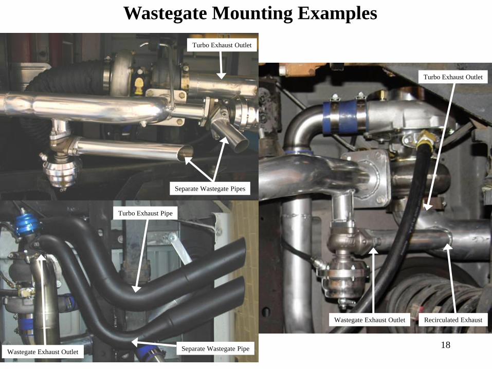
Wastegate Mounting Examples
Recirculated Exhaust
Separate Wastegate Pipes
Wastegate Exhaust Outlet
Turbo Exhaust Outlet
Turbo Exhaust Outlet
Wastegate Exhaust Outlet
Turbo Exhaust Pipe
Separate Wastegate Pipe

19
Wastegate Reference
The wastegate controls boost by allowing exhaust to bypass the turbo without increasing the speed of the turbine.
The ability to control boost requires a boost reference to push against the wastegate spring causing the wastegate to
open. The position of the boost reference will effect both wastegate & turbo response and the amount of boost the
system ultimately makes.
The first and most simple place to reference boost is from the compressor housing outlet. This point will be the most
accurate at controlling wastegate response and consistency. The draw back is that the response of the turbo will be
slightly slower and the amount of boost at the motor will be determined by not only the wastegate spring but also the
amount of pressure drop in the system. I.E. If the wastegate opens when the compressor housing sees 5 psi of boost
(.4 bar spring) and there is a 2 lb pressure drop in the system, then the motor will only see 3 psi of boost.
The second place to reference is from the intake manifold after the throttle body. A very simple place to get this
reference is to T off of the brake booster hose. This point will give the turbo better response but the wastegates
response will be slower. With the reference at the intake, the motor will see the full boost allotted by the wastegate
spring.
Wherever the wastegate is referenced from the port should be no smaller than the I.D. of the 1/4” hose provided. The
port size will directly effect the wastegate response time and consistency.

20BEST
BETTER
POORPOOR
BETTER
BEST
Wastegate Location

21
Intentionally Left Blank

22
Intake Pipe Examples

23
Intake Pipes
One of the largest benefits of a remote mount turbo kit is that it gives you the opportunity to achieve up to 50 percent intercooling without an intercooler! Always try to route the intake pipes where intercooling will be optimum.
Cooler intake charge = More horsepower
Take this into serious consideration when laying out the pipes. Most kits pushing up to 10 psi of boost will not need an intercooler. It is always a good idea to design the intake pipes in a way that will allow you to add an intercooler at a later date without having to re-design the whole kit. The OD of the intake piping is also a important factor to consider when building a kit. The most common outlet size of a turbo is 2” OD and the most common size throttle body is between 3” & 3.75” OD. Somewhere between the turbo and the motor, the pipe is going to have to expand in size to fit the throttle body. It is best to expand no more than a ½” at a time. If an expansion has to be larger than this, a “swedge” style expansion is recommended to promote smoother flow through the transition. Intake pipes may be mounted solid to the frame or body. Make sure that when the vehicle is on the ground that there is adequate ground clearance under the pipes. Keep the pipes away from any moving objects such as driveline, suspension, and steering. Also try to keep the intake pipes away from the heat of the exhaust.
Air Filter Location
Finding a suitable location for the air filter is a very important part of the turbo performance. Find a location for the filter that is not exposed to the outside elements, has a good source for cold air, and is close enough to the turbo so as not to effect spool up time.
• Locate the filter no more than 3’ away from the air inlet of the turbo.
• The pipes leading from the filter to the turbo should be no smaller than the size of the inlet on the turbo.
• Make sure the ducting from the filter to the turbo is as smooth as possible.
• Do not mount the air filter inside the passenger compartment unless it is in a sealed box with a good source of outside air.
• Use the supplied filter pre-charger for dusty or wet conditions only.

24
Engine Compartment Intake Pipe Examples
Cast Aluminum
ElbowIntake Pipe
Blow Off Valve
Throttle Body
Throttle Body
Throttle Body
Throttle Body
MAF Sensor
MAF Sensor
Intake Pipe
Intake Pipes
Intake Pipe
Intercooler
25
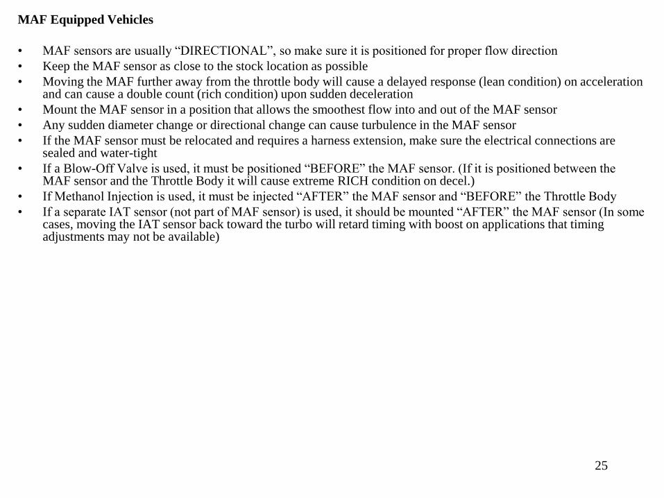
MAF Equipped Vehicles
• MAF sensors are usually “DIRECTIONAL”, so make sure it is positioned for proper flow direction
• Keep the MAF sensor as close to the stock location as possible
• Moving the MAF further away from the throttle body will cause a delayed response (lean condition) on acceleration and can cause a double count (rich condition) upon sudden deceleration
• Mount the MAF sensor in a position that allows the smoothest flow into and out of the MAF sensor
• Any sudden diameter change or directional change can cause turbulence in the MAF sensor
• If the MAF sensor must be relocated and requires a harness extension, make sure the electrical connections are sealed and water-tight
• If a Blow-Off Valve is used, it must be positioned “BEFORE” the MAF sensor. (If it is positioned between the MAF sensor and the Throttle Body it will cause extreme RICH condition on decel.)
• If Methanol Injection is used, it must be injected “AFTER” the MAF sensor and “BEFORE” the Throttle Body
• If a separate IAT sensor (not part of MAF sensor) is used, it should be mounted “AFTER” the MAF sensor (In some cases, moving the IAT sensor back toward the turbo will retard timing with boost on applications that timing adjustments may not be available)

26
BLOW OFF VALVE INSTALLATION
MAF SensorBlow Off Valve
Intercooler
Throttle Body

27
Blow Off Valve
The Blow Off Valve is designed to dump the boost pressure from the intake tubing when the throttle is rapidly closed during boosted driving. This prevents the boost pressure from exiting back through the turbocharger and dramatically decreasing the turbocharger rpm (a condition called “compressor surge”). This condition mostly applies to manual transmission vehicles during shifting.
The Blow Off Valve is activated if two conditions happen at the same time. If there is (1) - Boost in the intake tubing and (2) - Vacuum in the intake manifold, the Blow Off Valve will open to let out the boost pressure in the intake tubing. Dumping this boost pressure during a throttle “lift” allows the turbocharger to “coast” and maintain most of the turbocharger rpm so that it is ready to provide boost quickly rather than having to completely spool up again in the next gear.
Try to mount the BOV close to the vacuum source at the intake manifold. The longer the hose to the BOV, the slower the response of the BOV.
The BOV must be connected to a high-flow Vacuum/Boost source which will supply boost to the diaphragm to assist the BOV spring in keeping the valve closed during boost and supply a vacuum signal to the diaphragm to open the valve during a throttle lift. Try to use at least ¼” I.D. hose as smaller hose will cause a slower response of the BOV.
The BOV should be mounted between the turbocharger and the throttle body. On MAF sensor equipped vehicles, the BOV must be mounted BEFORE the MAF sensor. On intercooler equipped systems, the BOV should be mounted before the intercooler, but it can be mounted after if necessary.
BOV springs are available in 7, 9, and 11 psi rates. The standard rate is an 11 psi spring. This spring rate does not reference the boost level of the turbo system. It is related to the intake manifold vacuum that the engine produces. Most vehicles below 4000 feet of elevation will require the 11 psi spring as they will have approximately 18-20 inches of vacuum. Vehicles at high elevation (over 4000 feet) will typically require the 9 psi spring as they will have approximately 14-16 inches of vacuum. If the BOV is slow to respond, a lighter spring will quicken the response time. However, a spring which is too light may cause the BOV to hang open at idle.

28
Oil Supply Examples
Oil Supply
Line
90 degree
AN FittingOil Adapter
Plate (fits
between block
and stock plate)
Oil Supply Line
Brass T &
AN Fitting
Stock Oil
Pressure Sensor
Oil Supply Line
Brass T &
AN Fitting
Stock Oil
Pressure Sensor
45 Degree
AN Fitting
Factory Blockoff
Plate Drilled &
Tapped to 1/8” NPT
Oil Supply LineBrass AN Fitting
Brass T/Pressure
Sensor Adapter
Stock Oil
Pressure Sensor
Oil Supply Line

29
Oil Supply
The turbo requires a filtered, pressurized oil supply. This oil supply is usually sourced from near the oil filter on the engine and is typically T’d into the port for the oil pressure sending unit. An 1/8” NPT T fitting is provided which can be screwed into the block at the location of the oil pressure sending unit. The sending unit can then be screwed into the end of the T fitting. A #4 AN fitting is provided to screw into the side of the T fitting which will then be connected to the stainless oil supply hose that runs to the turbocharger. (Note: This may not fit your particular application.)
Once the oil supply connection has been made, connect the stainless oil supply hose to the #4 AN fitting. Then route the hose back to the top of the turbocharger and connect to the inlet side of the inline check valve. Route the hose in such a way that there is optimal cooling to the oil hose from passing air (keep away from hot exhaust and enclosed areas). Secure the hose using the nylon ties provided keeping it away from Hot, Sharp, and/or Moving objects. (Note: It is helpful to cover the open end of the hose with tape to prevent debris from entering hose during installation.)
Check Valve
Oil Supply Line

30
Rubber Oil Pump
Insulators
YELLOW Wire To
Terminal Nearest Oil
Pump Outlet
BLACK Wire To
Terminal Nearest Oil
Pump Inlet
Pressure Switch 3-8
PSI Adjustment
Oil Return Hose From
Turbo Oil Outlet
Remote Mounted Oil Pump Assembly
Diagram 2a
Oil Pump Outlet
Oil Return Hose
To Engine
White Wire
Brass T Fitting On
Oil Pump InletOil Pump Inlet
Black Wire

31
Oil Pump
Regardless of popular belief, the turbocharger does not have any “Magic” seals that contain the oil within the turbocharger. The turbo shaft runs through 2 bushing type bearings which have a lot of clearance. The oil gravity drains out of the center section through the turbo oil outlet flange. If the oil level inside the turbo center section reaches the level of the shaft, it will flow along the shaft and out into the compressor and turbine housings. There are 3 major times that oil control can be a problem. While the engine is running, there is obviously a lot of oil flow entering the top of the turbocharger. If this oil is not scavenged out of the bottom of the turbocharger (keeping the oil level inside the center section below the shaft level) the oil buildup inside the turbo, combined with the pressure of the oil coming into the turbo will cause the oil to be expelled into the compressor and turbine housings. This condition can be prevented by proper scavenging with the oil pump.
The second oil control problem can occur after the engine has been shut off. If oil enters the turbocharger either from the oil supply (TOP) or from the oil outlet (BOTTOM). Any oil in the entire oiling system (engine included) that is above the level of the turbocharger shaft will tend to gravity feed to the lowest point in the system. The oil in the pressure side ofthe system (all engine oil galleys and the turbo oil supply hose) will gravitate to the lowest point and put pressure on the inlet of the turbocharger. The check valve at the turbo oil inlet is designed to prevent any flow of oil into the turbocharger unless oil pressure from a “running” engine is present.
The third oil control problem can occur when the oil return side of the system drains backwards and fills the turbocharger from the bottom and raises the level of the oil to the level of the shaft. All of these oil control problems can be avoided by proper placement and routing of the oil pump and hoses.
NOTE: High volume pumps are available from STS for high boost and/or twin turbo applications. If the oil alarm buzzer sounds at high boost (10+ psi), this is usually caused by exhaust pressure entering the center section of the turbocharger which can increase the pressure in the oil outlet hose and close the pressure switch which is preset at 3 psi. This switch can be adjusted up to 8 psi if necessary. This exhaust pressure condition typically does not cause oil control problems.

32
Oil Pump Mounting Examples
PS Cooler
Relocated
Front Cross Member
3# Pressure Switch
Oil Pump Outlet
Oil Pump Inlet
Oil Pump
Mounting Bracket
Frame Rail
Oil Pump Outlet 3# Pressure switch
Oil Pump Inlet
The STS Oil Pump is very versatile. The pump
is reversible so it can pump oil in either
direction to simplify oil hose routing. The
pump can be mounted in virtually any position.
It is recommended, however, that it not be
mounted with the motor body below the pump
head. In other words, it is not recommended
that the pump be mounted upside-down.
When mounting the oil pump, you may need to
first mount the pump to a bracket and then
mount the bracket to the frame. In the upper
diagram, notice how the oil pump bracket
doubles as a power steering cooler re-locator
bracket.
33
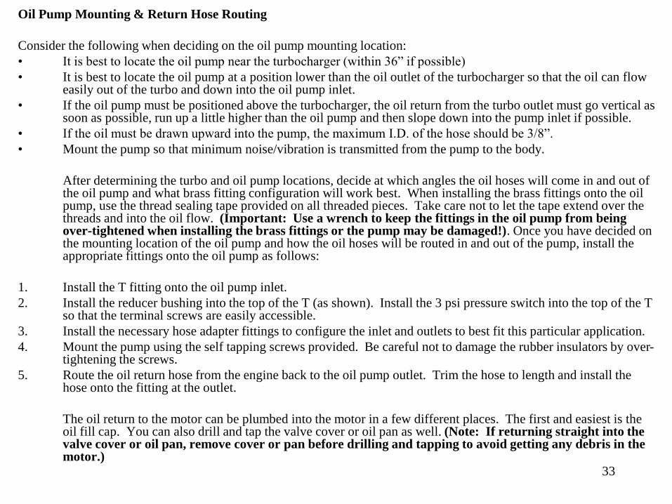
Oil Pump Mounting & Return Hose Routing
Consider the following when deciding on the oil pump mounting location:
• It is best to locate the oil pump near the turbocharger (within 36” if possible)
• It is best to locate the oil pump at a position lower than the oil outlet of the turbocharger so that the oil can flow easily out of the turbo and down into the oil pump inlet.
• If the oil pump must be positioned above the turbocharger, the oil return from the turbo outlet must go vertical as soon as possible, run up a little higher than the oil pump and then slope down into the pump inlet if possible.
• If the oil must be drawn upward into the pump, the maximum I.D. of the hose should be 3/8”.
• Mount the pump so that minimum noise/vibration is transmitted from the pump to the body.
After determining the turbo and oil pump locations, decide at which angles the oil hoses will come in and out of the oil pump and what brass fitting configuration will work best. When installing the brass fittings onto the oil pump, use the thread sealing tape provided on all threaded pieces. Take care not to let the tape extend over the threads and into the oil flow. (Important: Use a wrench to keep the fittings in the oil pump from being over-tightened when installing the brass fittings or the pump may be damaged!). Once you have decided on the mounting location of the oil pump and how the oil hoses will be routed in and out of the pump, install the appropriate fittings onto the oil pump as follows:
1. Install the T fitting onto the oil pump inlet.
2. Install the reducer bushing into the top of the T (as shown). Install the 3 psi pressure switch into the top of the T so that the terminal screws are easily accessible.
3. Install the necessary hose adapter fittings to configure the inlet and outlets to best fit this particular application.
4. Mount the pump using the self tapping screws provided. Be careful not to damage the rubber insulators by over-tightening the screws.
5. Route the oil return hose from the engine back to the oil pump outlet. Trim the hose to length and install the hose onto the fitting at the outlet.
The oil return to the motor can be plumbed into the motor in a few different places. The first and easiest is the oil fill cap. You can also drill and tap the valve cover or oil pan as well. (Note: If returning straight into the valve cover or oil pan, remove cover or pan before drilling and tapping to avoid getting any debris in the motor.)

34
PCV Switch Valve
PCV Filter
To Filtered Air Source
After The MAF Sensor
To Crank Case Port
PCV Switch Valve
Mounting Bracket/Ground
Switch Valve
Trigger Terminal

35
INTENTIONALLY LEFT BLANK

36
1PSI Switch / PCV Checkvalve Assembly
To Intake Manifold Port
To Crank Case Port #2
To Intake Manifold Port
To Intake Manifold PortTo Intake Manifold Port

Page 37
The above diagram illustrates a few possible different configurations of the 1PSI switch/PCV checkvalve assembly. This assembly must be installed inline between the intake manifold PCV port and the crank case port #2. Note the direction of thearrow on the one way checkvalve in reference to the crank case and intake manifold.

38
MAF PCV System
There are 4 different crank case/intake manifold ports that you need to first identify before you can layout the PCV system.
1. Fresh air source – This port will typically be between the MAF sensor and the throttle body.
2. Crank case port #1 – This port will be hooked to the fresh air source.
3. Crank case port #2 – This port will be hooked to the intake manifold port.
4. Intake manifold port – This port will evacuate the fumes from the crank case under non-boosted driving conditions.
The diagram below illustrates the air flow through a non-turbo PCV system.
Filtered Air Source
Crank Case Port #2Crank Case Port #1
Intake Manifold (under vacuum)MAF Sensor Throttle Body
Crank Case
Air Filter

39
The diagram below illustrates the air flow through a turbo PCV system under non-boosted driving conditions.
Filtered Air Source
Crank Case Port #2Crank Case Port #1
Intake Manifold (under vacuum)MAF Sensor Throttle Body
Crank Case
Air Filter
1PSI Switch
PCV Checkvalve

40
The diagram below illustrates the air flow through a turbo PCV system under boosted driving conditions. Once the
1PSI switch sees 1PSI of boost from the intake manifold, it will power the terminal on the switch valve allowing the
crank case to vent to atmosphere. The PCV checkvalve keeps the boost from entering the crank case.
Filtered Air Source
Crank Case Port #2Crank Case Port #1
Intake Manifold (under boost)MAF Sensor Throttle Body
Crank Case
Air Filter
1PSI Switch
PCV Checkvalve
Crank Case
Bow By Ventilation
Zero Flow Under Boost
41
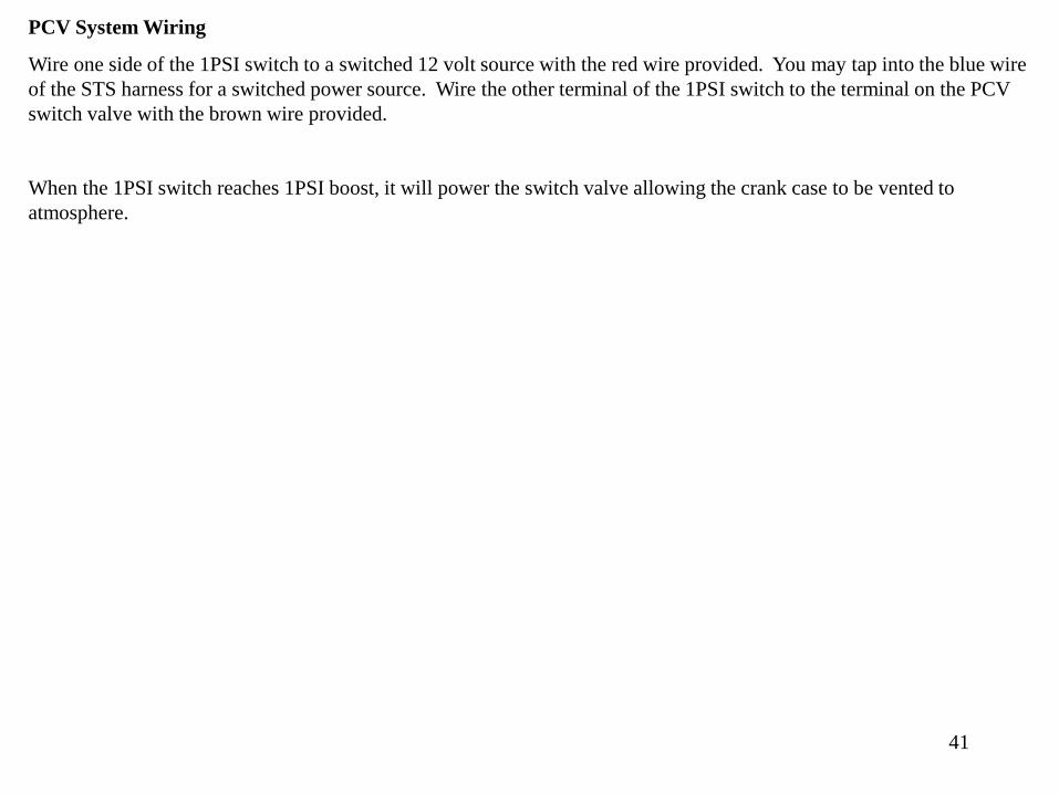
PCV System Wiring
Wire one side of the 1PSI switch to a switched 12 volt source with the red wire provided. You may tap into the blue wire
of the STS harness for a switched power source. Wire the other terminal of the 1PSI switch to the terminal on the PCV
switch valve with the brown wire provided.
When the 1PSI switch reaches 1PSI boost, it will power the switch valve allowing the crank case to be vented to
atmosphere.

NON-MAF PCV System
The crank case of a boosted vehicle can see large fluctuations of pressure due to the increased blow-by created. There
must be at least one filtered port allowing the crank case to vent. A breather filter on the valve cover is usually sufficient.
The factory PCV valve must allow the intake to draw air from the crank case under non-boosted driving conditions. Once
boost is present, the PCV valve must not allow air to get from the manifold to the crank case or it will boost the crank
case. The factory PCV valve needs to be in good condition and shut off the flow of air from the intake manifold into the
crank case. A check valve may need to be installed inline with PCV valve if the factory PCV valve is not capable of
completely shutting off this airflow under boost.

43
Oil Pump Wiring Example
Diagram 16
Oil Pump Oil Outlet
RED Wire To Outlet Side
Of Oil PumpBLACK Wire To Inlet
Side Of Oil Pump
Oil Hose From Turbo
Protective Rubber
Cap Over Pressure
Switch
Oil Inlet
Rear Wiring Harness
BLACK Ground Wire to Frame
Oil Return Hose
To Engine
BLACK And WHITE
Wire Pair To Terminals
On Pressure Switch

44
Wiring Harness
Before installing the wiring harness, make sure that the oil pump is installed in its final position. First determine where the relay(s) will be located. Connect the rest of the leads as follows:
1. Red power wire with fuse holder connects to + battery terminal. This provides power to the harness.
2. Black ground wire connects to a suitable ground. This provides a ground for the harness.
3. Black and Yellow wires connects to the top of the oil pump with the Yellow wire on the outlet side of the pump. The Yellow wire provides power to the oil pump from the relay. The Black wire is the pump ground.
4. Black and white wires connect to the 3# pressure switch on the inlet side of the oil pump. The black wire is a ground. When the switch sees 3# of pressure in the oil return line it grounds the piezo buzzer, which makes it buzz.
5. Blue wire connects to a switched 12 volt source. This provides power to the secondary relay which powers the oil pump.
6. Run the piezo buzzer and the oil pump hi/low switch into the passenger compartment. Secure the
piezo buzzer under the dash. This tells you when there is pressure in the oil return line indicating
a possible oil return problem.
Be sure to route the harness in a clean fashion avoiding any hot, sharp, or moving objects. Once all the connections are made, the wires may be shortened up to clean up the appearance. It is strongly recommended to solder and shrink wrap all electrical connections.

Page 45
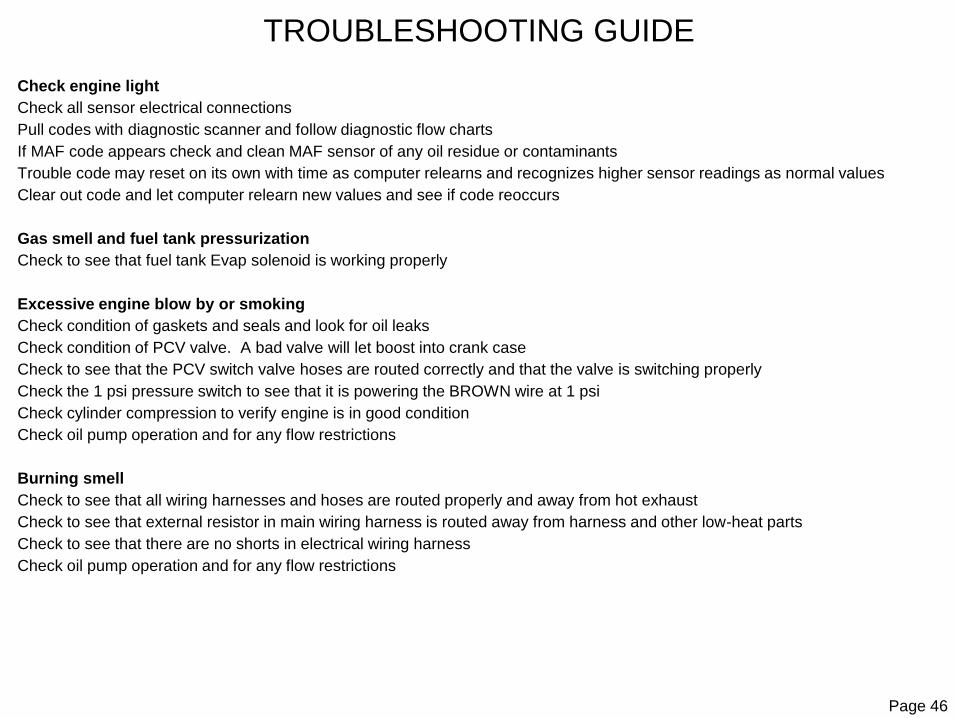
TROUBLESHOOTING GUIDE
Oil pump alarm sounds
Check to see if oil pump is working
If pump is working, check oil pump electrical connections to see that they aren’t reversed
If pump is not working, check inline fuse in main harness and electrical harness connections
Check relays to make sure they are plugged in properly
Check inline voltage resistor for voltage on each side of resistor
Oil pump is noisy
Oil pump will be slightly noisy upon startup and when cold but should get quieter as system warms and as pump wears in
Jumping pressure switch electrical connectors on charge air tube should run pump at high speed
If pump always runs at high speed, check pressure switch continuity, secondary relay continuity, and harness for shorts.
Check to see if oil pump or housing are rubbing on frame and that rubber insulators are in good shape
Turbo won’t boost, produces low boost, or has excessive spool time
Check intake tubing for any leaks at tubes or hose connections
Check exhaust system for any leaks
Check wastegate to see that valve isn’t stuck open
Spool up time will decrease as the turbocharger breaks in and should improve over first few days of driving
Check condition of air filter or pre-charger filter cover
Detonation
Check for lean condition, O2 readings should be above .900 volts at WOT
Check Octane rating of fuel and use premium fuel only
Check boost level to see that it isn’t running too much boost
Check wastegate and hose connections
Squeaking or rattling noise
Check to see that all mounts and tubing is secure
Check to see that tubing and hose clamps are not rubbing on any moving parts
Page 46
TROUBLESHOOTING GUIDE
Check engine light
Check all sensor electrical connections
Pull codes with diagnostic scanner and follow diagnostic flow charts
If MAF code appears check and clean MAF sensor of any oil residue or contaminants
Trouble code may reset on its own with time as computer relearns and recognizes higher sensor readings as normal values
Clear out code and let computer relearn new values and see if code reoccurs
Gas smell and fuel tank pressurization
Check to see that fuel tank Evap solenoid is working properly
Excessive engine blow by or smoking
Check condition of gaskets and seals and look for oil leaks
Check condition of PCV valve. A bad valve will let boost into crank case
Check to see that the PCV switch valve hoses are routed correctly and that the valve is switching properly
Check the 1 psi pressure switch to see that it is powering the BROWN wire at 1 psi
Check cylinder compression to verify engine is in good condition
Check oil pump operation and for any flow restrictions
Burning smell
Check to see that all wiring harnesses and hoses are routed properly and away from hot exhaust
Check to see that external resistor in main wiring harness is routed away from harness and other low-heat parts
Check to see that there are no shorts in electrical wiring harness
Check oil pump operation and for any flow restrictions

Page 47
Oil leaking at the turbochargers and/or oil smoke from the exhaust is almost always an oiling system problem or an electricalproblem and almost never a turbocharger problem. Any time oil is leaking into the turbine or compressor of the turbocharger, ittypically means that the oil level inside the turbocharger is being allowed to rise up to or past the level of the shaft. This is usually caused because the oil is NOT being properly evacuated from the turbocharger by the oil system. There are no "Magic" seals inside the turbo to contain oil pressure within the turbo. The turbocharger basically has a loose fitting shaft that is supported within 2 bushings. If the oil level inside the turbo reaches the level of the shaft, it will overflow and spill out through the bushings just as filling up a cup past the top will cause it to spill over the sides. Keeping this in mind, here are the steps to diagnose the problem:
NEW INSTALLATIONS: For an oil problem on a vehicle with a new system that hasn't been running (not a vehicle that has been working fine but now has an oiling issue) we need to cover the basics. First, review the installation manual to make sure that all the steps were followed concerning the following:
OIL PUMP INSTALLATION (including the polarity and wire placement - YELLOW wire always goes to the OUTLET side of the pump)
OIL HOSE ROUTING (this is actually very critical and must be done EXACTLY as the manual says)
ELECTRICAL HARNESS INSTALLATION and more specifically (TESTING OF THE ELECTRICAL SYSTEM at the end of the manual)
CLOCKING OF THE TURBOCHARGERS (must be straight up and down with oil outlet exactly straight down)
OIL PUMP BREAK IN PROCEDURE (must be followed and the oil pump should be run on HIGH SPEED for first 50 miles)
TROUBLESHOOTING GUIDE

Page 48
ELECTRICAL SYSTEM TESTS:
With the ignition key in the “ON” position and the engine running, toggle the switch on the main relay. This will
manually override the pump controls and run the oil pump on “HIGH” speed. You should hear the pump get audibly
louder when the switch is in the “HIGH” position. This can be used to help troubleshoot any oiling system problems
and can be used for extreme cold weather and/or racing conditions to ensure optimal oil scavenging from the turbos.
Return this switch to the “LOW” position to perform the following tests. Once the electrical system tests are
performed, switch the override switch back to “HIGH” for the first 50 miles of driving then return the switch to the
“LOW” position for normal operation.
With the engine running, use a jumper wire to connect the two terminals of the pressure switch near the PCV switch
valve. You should hear oil pump get louder and be able to feel the PCV switch valve click.
Remove jumper wire and connect it across pressure switch terminals at the oil pump inlet. This should cause buzzer
alarm to sound in passenger compartment. Remove the jumper wire and shut off the engine. Once electrical system
tests are complete, install the rubber protective caps on the two pressure switches and reinstall the rear splash panel.
(NOTE: The pump over-ride should be set to the normal operating mode for tuning as the PCV vent will pull
“non-metered” air in while the pump is in the “HIGH” speed mode. During normal operation, the PCV system
functions normally and pulls in “metered” air to prevent idle and/or drivability problems.)
Install the tuning as per the tuning instructions then test drive vehicle and make sure that the turbocharger is working
properly and producing the proper amount of boost. (The standard kit should produce about 5-psi boost). Check for
proper air/fuel mixtures (AFR should be at least 11.5:1 or .920 mV) and make sure that there is no Knock Retard or
Detonation.
Check and top off engine oil. With the oil cap off, hold the cap over the oil fill neck and start the vehicle to check for oil flow out
of the oil return hose. If oil is ‘squirting’ out of the cap, shut engine off and reinstall the oil cap.
Test drive vehicle and make sure that the turbocharger is working properly and producing the proper amount of boost. The
standard kit should produce about 5-psi boost.

Page 49
Recheck all connections, clamps, and brackets for proper tightness and routing. (Important: Inspect the wiring harness routing
near the transmission and exhaust system for any evidence of the loom melting due to high heat.
If the loom is getting too hot, reroute the harness and secure harness to protect it from excessive heat.)
Vehicle performance should increase over the next few days of driving as the turbocharger breaks in, allowing quicker spool-up,
and as the computer relearns and adjusts to boost conditions. The “Check Engine” light may come on during the next few
weeks of driving, as the computer will see sensor values that are out of the “normal range” of what it is used to seeing. The light
should go off and reset each time you drive the vehicle. It is recommended that you check and keep track of any trouble codes
that are set in the computer to make sure that no damage is done to your vehicle.
The oil pump should decrease in noise level as oil temperature rises and also decrease over time as the pump breaks in.
If you experience any problems, refer to the Troubleshooting Guide. If you can’t solve the problem that is related to the
turbocharger system, please email Technical Support or call 866-464-6543.

Page 50
ELECTRICAL SYSTEM TESTS:
With the key turned to the ON position, you should be able to hear the oil pump turn on for approximately 2 seconds (some
vehicles including the 05 GTO, 05 C6, and 05 Mustang are different - refer to install manual). If the pump isn't running during this
test, you need to check the BLUE wire in the STS harness to make sure it is getting power from the fuel pump wire. If you have
power, make sure that the 15 amp fuse is installed in the wiring harness. If the pump is still not running at this stage, it may be
easier to unplug the BLUE wire from the fuel pump T-Tap and supply 12v+ to the BLUE wire directly from the battery. This will
power up the system so you can do the diagnostic checks on the electrical harness and not have to keep cycling the key ON and
OFF. Once you have constant power to the BLUE wire, perform the following tests using a multimeter and/or a test light:
1- Check for voltage at the BLUE wire at the MAIN RELAY terminal (85). This is the trigger voltage that turns the relay ON. If
there is no voltage, check the BLUE wire for a short and for power.
2- Check for voltage at the LARGE RED single wire at the MAIN RELAY terminal (30). This is the power supply for the relay. If
there is no voltage there, check the 15 amp fuse for power and check the power supply to the RED wire at the fuse block or
power supply.
3- Check the BLACK wire at the MAIN RELAY terminal (86) for GROUND. This is the ground supply for the relay. This can be
done by placing the test light clip on the battery (+) terminal and probing the BLACK wire terminal. Check the ground wire
connection at the frame and/or factory ground location according to the instruction manual.
4- Check for voltage at the SMALL RED wire(s) at the MAIN RELAY terminal (87). This is the relay output voltage. If there is no
voltage at this wire and the previous tests passed, the relay is bad. Replace the relay (you can try swapping the secondary relay
for the main relay). If swapping the relays puts voltage to the small RED wire, the oil pump should run but won't be able to switch
speeds. (You may need to change the position of the high speed switch to get the oil pump to turn on). The relay can be replaced
with a common automotive 30 amp (fan style) relay available at most auto parts stores.
5- Check for voltage at the SMALL RED wire at the SECONDARY RELAY terminal (30). This is the power supply for the
secondary relay. If there is no voltage, check the SMALL RED wire for short or bad connection at the relay terminals.
6- Check for voltage at the YELLOW wire at the SECONDARY RELAY center terminal (87a). This is the output voltage during
the normally closed (LOW SPEED) position. Check for voltage at the BROWN or BLUE wire at the SECONDARY RELAY
terminal (85). There should be NO voltage during normal operation (LOW SPEED). If there is voltage, switch the oil pump speed
over-ride switch (if applicable). This should cut the voltage to the BLUE or BROWN wire and supply voltage to the YELLOW wire
at terminal (87a). If the previous tests pass and there is no output voltage at terminal (87a) then the SECONDARY RELAY is
bad. The relay can be replaced with a common automotive 30 amp (fan style) relay available at most auto parts stores.
Page 51
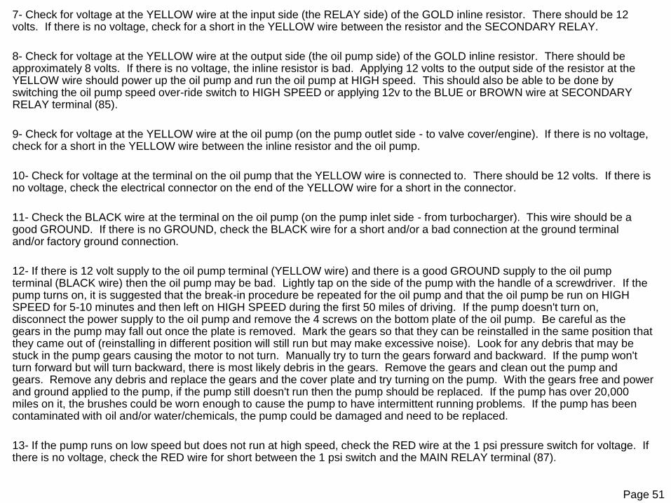
7- Check for voltage at the YELLOW wire at the input side (the RELAY side) of the GOLD inline resistor. There should be 12 volts. If there is no voltage, check for a short in the YELLOW wire between the resistor and the SECONDARY RELAY.
8- Check for voltage at the YELLOW wire at the output side (the oil pump side) of the GOLD inline resistor. There should be approximately 8 volts. If there is no voltage, the inline resistor is bad. Applying 12 volts to the output side of the resistor at the YELLOW wire should power up the oil pump and run the oil pump at HIGH speed. This should also be able to be done by switching the oil pump speed over-ride switch to HIGH SPEED or applying 12v to the BLUE or BROWN wire at SECONDARY RELAY terminal (85).
9- Check for voltage at the YELLOW wire at the oil pump (on the pump outlet side - to valve cover/engine). If there is no voltage, check for a short in the YELLOW wire between the inline resistor and the oil pump.
10- Check for voltage at the terminal on the oil pump that the YELLOW wire is connected to. There should be 12 volts. If there is no voltage, check the electrical connector on the end of the YELLOW wire for a short in the connector.
11- Check the BLACK wire at the terminal on the oil pump (on the pump inlet side - from turbocharger). This wire should be a good GROUND. If there is no GROUND, check the BLACK wire for a short and/or a bad connection at the ground terminal and/or factory ground connection.
12- If there is 12 volt supply to the oil pump terminal (YELLOW wire) and there is a good GROUND supply to the oil pump terminal (BLACK wire) then the oil pump may be bad. Lightly tap on the side of the pump with the handle of a screwdriver. If the pump turns on, it is suggested that the break-in procedure be repeated for the oil pump and that the oil pump be run on HIGH SPEED for 5-10 minutes and then left on HIGH SPEED during the first 50 miles of driving. If the pump doesn't turn on, disconnect the power supply to the oil pump and remove the 4 screws on the bottom plate of the oil pump. Be careful as the gears in the pump may fall out once the plate is removed. Mark the gears so that they can be reinstalled in the same position that they came out of (reinstalling in different position will still run but may make excessive noise). Look for any debris that may be stuck in the pump gears causing the motor to not turn. Manually try to turn the gears forward and backward. If the pump won't turn forward but will turn backward, there is most likely debris in the gears. Remove the gears and clean out the pump and gears. Remove any debris and replace the gears and the cover plate and try turning on the pump. With the gears free and power and ground applied to the pump, if the pump still doesn't run then the pump should be replaced. If the pump has over 20,000 miles on it, the brushes could be worn enough to cause the pump to have intermittent running problems. If the pump has been contaminated with oil and/or water/chemicals, the pump could be damaged and need to be replaced.
13- If the pump runs on low speed but does not run at high speed, check the RED wire at the 1 psi pressure switch for voltage. If there is no voltage, check the RED wire for short between the 1 psi switch and the MAIN RELAY terminal (87).

Page 52
14- Apply 1+ psi to the pressure switch (or just jumper the switch for testing purposes to test the electrical system only and notthe switch). Check the BROWN or BLUE wire at the SECONDARY RELAY terminal (85). If there is no voltage, check for a short between the SECONDARY RELAY and the 1 psi pressure switch.
15- The 1 psi pressure switch can be checked with a manual vacuum/pressure pump. Apply 1+ psi to the switch and check for continuity across the terminals. Less than 1 psi should be OPEN. More than 1 psi should be CLOSED and put voltage across the terminals. If the switch requires 3+ psi to CLOSE the switch, then the pressure switch is incorrect. The HEX (wrench) portion of the switch should be sized to fit a 7/16" wrench. If the switch is 1/2" on the HEX, it is most likely a 3.1 psi switch. There should be a number stamped on the side of the metal part of the switch that says "1.0" for the 1 psi switch and "3.1" for the 3.1 psi switch. The 3.1 psi switch should be on the inlet side of the oil pump assembly.
16- Check the BLACK wire at the SECONDARY RELAY terminal (86) for ground. If there is no GROUND supply there, check the BLACK wire for short between the factory ground terminal and/or frame rail and the relay.
17- Check the YELLOW wire at the SECONDARY RELAY terminal (87) for voltage. This is the output for the OPEN condition of the relay. If there is voltage at the RED wire, ground at the BLACK wire and voltage at the BROWN or BLUE wire, this YELLOW wire should have voltage. If there is no voltage, then the relay is bad. The relay can be replaced with a common automotive 30amp (fan style) relay available at most auto parts stores. The NOTE: YELLOW wires at the SECONDARY RELAY terminals (87 and 87a) are connected after the inline resistor. 12 volts applied to terminal 87 will be reduced through the inline resistor to approximately 8 volts to the oil pump. This 8 volts will also feed back through the YELLOW wire to terminal 87a. 12 volts applied to terminal 87a will supply a full 12 volts to the oil pump. This voltage will also feed back through the YELLOW wire to terminal 87. Keep this in mind when troubleshooting voltages at the SECONDARY RELAY YELLOW wires.
NOTE: It is recommended that the BLUE fuel pump supply wire be soldered to the fuel pump wire to prevent the possibility of an intermittent short in the oiling system. The oil alarm buzzer is powered by this BLUE wire. A disruption in the power to the BLUE wire will result in the oil pump alarm not working.
If all of the electrical system seems to be working fine, the problem most likely is an oil flow issue. Then there is more oil getting supplied to the turbo than is being evacuated from the turbo. This typically happens 3 different ways: 1- Oil is draining back into the turbo from the oil return hose when the engine is OFF or 2- Oil is draining into the turbo through the oil supply hose while the engine is OFF or 3-the engine is supplying more oil to the turbo while it is running than the STS oil pump is evacuating from the turbocharger.

Page 53
Once the basics have been rechecked and check out OK, make sure that the ELECTRICAL SYSTEM TESTS at the end of the instruction manual have been done and that everything is working as described in the tests. This includes making sure that the oil pump is operating with the fuel pump and cycles on for 2-3 seconds each time the key is cycled to the ON position (some applications don't cycle for 2-3 seconds). There are often several wires of the same color and tapping into the wrong wire can produce intermittent oil pump issues. Most oiling system problems are related to an electrical problem. The following tests will walk you through diagnosing the electrical system:
1- Oil in the return hose can drain back into the turbocharger if the front of the vehicle is raised at a steep angle. Avoid parking the car with the front of the vehicle substantially higher than the rear. In this situation, park the vehicle nose down if possible. If the vehicle must be parked or have nose raised up (such as loading on a flat bed tow truck) then cycle the ignition switch several times to allow the oil pump to run and evacuate the return line completely. This situation can also be caused by improperly routing the oil return hose. The hose should remain flat for most of the distance from the rear to the front of the vehicle. Any elevation changes of the return hose should be done in the shortest run possible so that the volume of oil that will drain back will be at a minimum. The typical symptom will be oil or smoke from the exhaust upon starting the engine or revving up the engine after a start and/or puddling of oil under the turbo after the vehicle sits for 1/2 hour or so.
2- When the engine is shut off, most of the engine is still full of oil and will take some time to drain back to the pan. This residual oil pressure in the engine will push the oil through the oil supply hose toward the turbo after the engine is shut off. There is a check valve at the turbocharger inlet or in-line before the turbocharger to prevent oil from entering the turbocharger while theengine is off. If this check valve leaks, oil can continue to flow into the turbocharger while the engine is off. The typical symptom will be oil or smoke from the exhaust upon starting the engine or revving up the engine after a start and/or puddling of oil under the turbo after the vehicle sits for 1/2 hour or so. To test the check valve, remove the stainless supply hose from the check valve inlet. Remove the check valve from the turbocharger oil inlet or T fitting (depending on application). Reinstall the hose onto the inlet of the check valve. Hang the check valve down below the turbo and place into a bucket or suitable oil container. Start the vehicle and let idle until a steady stream of oil is coming out of the check valve. Turn the engine off. The oil should drip a few times from the check valve and then stop. Place the check valve over a small cup or container. Monitor the oil leakage from the check valve for 15 minutes. No oil should drip from the check valve once the residual oil has drained from the check valve outlet. A bad check valve will typically drip once every 5 to 30 seconds. A leaking check valve can be cleaned/flushed out andretested. Leaking valves need to be replaced. Contact your local STS Power Dealer or STS Technical Support for a replacement check valve. Reinstall the good valve and connect the oil supply hose, being careful not to get debris or thread tape into the flow of oil.
Page 54
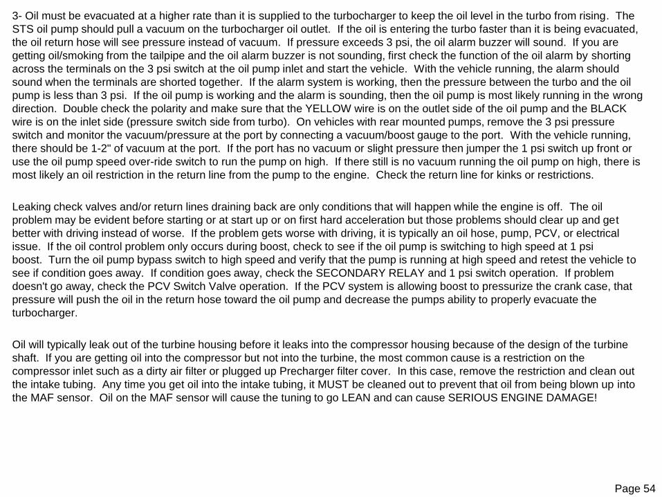
3- Oil must be evacuated at a higher rate than it is supplied to the turbocharger to keep the oil level in the turbo from rising. The
STS oil pump should pull a vacuum on the turbocharger oil outlet. If the oil is entering the turbo faster than it is being evacuated,
the oil return hose will see pressure instead of vacuum. If pressure exceeds 3 psi, the oil alarm buzzer will sound. If you are
getting oil/smoking from the tailpipe and the oil alarm buzzer is not sounding, first check the function of the oil alarm by shorting
across the terminals on the 3 psi switch at the oil pump inlet and start the vehicle. With the vehicle running, the alarm should
sound when the terminals are shorted together. If the alarm system is working, then the pressure between the turbo and the oil
pump is less than 3 psi. If the oil pump is working and the alarm is sounding, then the oil pump is most likely running in the wrong
direction. Double check the polarity and make sure that the YELLOW wire is on the outlet side of the oil pump and the BLACK
wire is on the inlet side (pressure switch side from turbo). On vehicles with rear mounted pumps, remove the 3 psi pressure
switch and monitor the vacuum/pressure at the port by connecting a vacuum/boost gauge to the port. With the vehicle running,
there should be 1-2" of vacuum at the port. If the port has no vacuum or slight pressure then jumper the 1 psi switch up front or
use the oil pump speed over-ride switch to run the pump on high. If there still is no vacuum running the oil pump on high, there is
most likely an oil restriction in the return line from the pump to the engine. Check the return line for kinks or restrictions.
Leaking check valves and/or return lines draining back are only conditions that will happen while the engine is off. The oil
problem may be evident before starting or at start up or on first hard acceleration but those problems should clear up and get
better with driving instead of worse. If the problem gets worse with driving, it is typically an oil hose, pump, PCV, or electrical
issue. If the oil control problem only occurs during boost, check to see if the oil pump is switching to high speed at 1 psi
boost. Turn the oil pump bypass switch to high speed and verify that the pump is running at high speed and retest the vehicle to
see if condition goes away. If condition goes away, check the SECONDARY RELAY and 1 psi switch operation. If problem
doesn't go away, check the PCV Switch Valve operation. If the PCV system is allowing boost to pressurize the crank case, that
pressure will push the oil in the return hose toward the oil pump and decrease the pumps ability to properly evacuate the
turbocharger.
Oil will typically leak out of the turbine housing before it leaks into the compressor housing because of the design of the turbine
shaft. If you are getting oil into the compressor but not into the turbine, the most common cause is a restriction on the
compressor inlet such as a dirty air filter or plugged up Precharger filter cover. In this case, remove the restriction and clean out
the intake tubing. Any time you get oil into the intake tubing, it MUST be cleaned out to prevent that oil from being blown up into
the MAF sensor. Oil on the MAF sensor will cause the tuning to go LEAN and can cause SERIOUS ENGINE DAMAGE!

Page 55
The least common oiling problem that we see is the turbocharger. To check the turbocharger, attempt to move the compressor shaft up and down. There is up to about .020" of play (up-down) in a good turbocharger. There should be no end play in the shaft (in-out). If the shaft moves enough that the compressor or turbine wheels can touch the housing and/or if there is end play in the shaft (in-out along the same axis as the shaft) then the turbocharger is damaged and will need to be rebuilt. If the oiling system checks out and you still suspect that the turbocharger is bad, you can perform the following test to verify a leaking turbo:
1- Clean the turbocharger so that there is no oil in the housings.
2- Remove the oil return flange from the bottom of the turbocharger.
3- Place a suitable container below the turbocharger so that the oil can flow out of the turbocharger and fall into the container.
4- Start the engine and let it idle. DO NOT RUN THE ENGINE LOW ON OIL AS SEVERE DAMAGE WILL RESULT!
5- Watch for oil leaking into the compressor housing and/or turbine housing.
6- After sufficient time, shut engine off and check turbine housing and compressor housing for oil.
7- Reassemble oil system components and top off engine oil.
If oil accumulates in the compressor or turbine housing during this process, the turbocharger will need to be repaired.
Some common oiling system problems are:
1- Turbocharger not clocked properly - oil drain flange is not straight down.
2- Oil hoses routed improperly - 5/8" oil return hose from turbo to oil pump must drain down to pump. The 5/8" hose can not pull oil up-hill. Only the 3/8" oil return hose can be routed so that the oil is pulled up-hill from the turbo to the oil pump.
3- Oil return hose is pinched between the transmission and the body or kinked and/or twisted causing a flow restriction.
4- Wiring harness is routed too close to exhaust and/or sharp object and has been damaged.
5- Inline resistor is getting too hot and/or gets pulled apart/damaged.
6- Fuel pump wire connection (T-Tap) at BLUE wire is shorting or has bad connection. Recommend soldering instead of temporary T-Tap connector.
7- Dirty or clogged air filter and/or restricted turbocharger compressor inlet.
8- Bad PCV valve and/or improperly functioning PCV system allowing boost to pressurize crank case.
9- Parking vehicle on an incline with front of vehicle raised higher than the rear of the vehicle.
10- Leaking oil check valve at turbo inlet.
11- Damaged turbocharger bearings.
Page 56
STS Turbo Systems – Safety Warning - Please Read!
IMPORTANT
Oil System Warning Buzzer
Your STS™ Turbo System is equipped with a safety system that will alert you in the event that your oil pump fails. This system is a buzzer that will be heard inside your vehicle. If you hear the Oil Alarm sound, immediately shut the engine off and safelypull over to the side of the road and contact STS Tech Support. Serious engine damage can occur if the pump stops while your engine is running. With the pump stopped, oil will flow out of the turbo and will not return to the engine.
Premium Fuel
STS Turbo recommends that you only use Premium Fuel, 91 Octane or higher, on vehicles equipped with the STS™ Turbo System. Premium fuel reduces pinging and detonation which can cause significant damage to your vehicle.
Engine Pinging or Detonation
If you hear pinging in your engine, back off the throttle immediately. Pinging is the sound of Detonation and can cause significant damage to the engine. If you hear pinging, do NOT drive the vehicle during this condition and call your local STS dealer immediately.
Heavy Towing
The STS Turbo System, like other turbo and supercharger systems, under certain heavy towing situations can create more power than a stock engine can handle. STS Turbo does not recommend using this system for heavy towing purposes.
Vehicle modifications
STS Turbo Systems were designed to fit stock vehicles. If you have modified your vehicle, modifications to the turbo system or your vehicle may be necessary to ensure the proper fit and safe use of the STS Turbo System. Inform your dealer of any aftermarket changes to your vehicle.
The STS turbo system is designed to provide enhanced power and engine performance. It could cause severe damage to your
vehicle if it is not properly installed or if your vehicle is not properly tuned and maintained for the system. Under some
circumstances, improper installation or use of the STS turbo system could result in serious personal injury or even death.
STS Turbo Systems can not accept responsibility for the proper maintenance or the proper operation of your vehicle. Please take
all necessary precautions to use the STS Turbo System strictly in accordance with all instructions and warnings.

Page 57
STS Safety Warning and Warranty Notice
SAFETY WARNING – PLEASE READ
The STS turbo system is designed to provide enhanced power and engine performance. It could cause severe
damage to your vehicle if it is not properly installed or if your vehicle is not properly maintained for the system.
Under some circumstances, improper installation or use of the STS turbo system could result in serious
personal injury or even death.
Neither Holley Performance, Inc. nor its authorized dealers can accept responsibility for the proper maintenance
or the proper operation of your vehicle. Please take all necessary precautions to use the STS turbo system
strictly in accordance with all instructions and warnings.
WARRANTY NOTICE – PLEASE READ
The liability of Holley Performance Products, Inc. and its authorized dealers relating to your use of the STS
turbo system is strictly limited. Please read the STS turbo system limited warranty carefully. In most cases,
the warranty is limited to repair or replacement of the system itself and does not cover:
Any damage to your vehicle or other property that results from your use of the STS turbo system
Any personal injury or death that results from your use of the STS turbo system
Any adverse effect of the STS turbo system on other warranties
Under some circumstances, applicable law may specifically prohibit us from disclaiming responsibility for
damage to your vehicle and/or for personal injuries or death caused by your use of the STS turbo system, in
which case our responsibility will be as provided by law. However, we urge you to exercise the utmost care in
properly installing and using the system so as to avoid personal injury and/or damage to your vehicle. You are
responsible for using the system safely and for evaluating the effect of such use on other warranties.

Page 58
STS Turbo products are covered by a Limited One-Year Warranty that covers certain defects in workmanship and materials.
Who is covered? This warranty covers the original purchaser of STS Turbo products in the United States and Canada.
What is covered and for how long? Holley Performance Products Inc. (“Holley”) warrants that STS Turbo products will be free from defects in material and
workmanship for the life of the product on the original car on which it was installed. Blemishes, marring of appearance, discoloration, internal rust, or surface rust
due to weather, road hazards, lack of maintenance, or extremes of heat of cold are not be considered defects under this Limited One-Year Warranty. Holley
warrants moving parts such as valves and actuators for one year. All claimed warranty products must have a return goods authorization (RGA) number and
returned to the place of purchase. The returned product must be accompanied with a copy of the original purchase receipt and the original purchasers contact
information.
What will Holley do? If there is a defect in material or workmanship, Holley will choose either to repair the defective part or replace it with a comparable, new
part, without charge for the repair or the replacement product. Purchaser’s remedies under this Limited One-Year Warranty are strictly limited to the repair or
replacement of the defective product. You must pay the cost of shipping the product back to Holley and for any labor or other costs, including any additional
parts, associated with removing the allegedly defective part and with the installation of the repaired or replacement part.
What is NOT covered? This warranty does not cover STS Turbo products that have been installed on any commercial or racing vehicle or that have been
damaged due to misuse, abuse, neglect, or accident, such as having been modified or altered; improperly installed, adjusted or repaired; welded; exposed to
corrosion, corrosive materials, other contaminants; or used in applications other than those recommended by STS Turbo on our website (www.holley.com).
How do I start the warranty claim process? To initiate the warranty process, the consumer must return the alleged defective product to the place of purchase with a dated receipt and completed applicable warranty claim tag. Warranty claims will be rejected if the date of purchase cannot be established by the consumer. Do not send products directly to Holley Performance Products. Holley Performance Products assumes no responsibility for products sent directly to Holley Performance Products.
What other conditions and exclusions apply? This warranty does not provide compensation for loss of time, loss of use of vehicle, labor cost, cost of
additional parts, shipping, inconvenience or other consequential or incidental damage. Some states do not allow the exclusion or limitation of incidental or
consequential damages, so these limitations or exclusions may not apply to you.
Holley’s maximum liability under this Limited One-Year Warranty shall not exceed the original cost of the product to the consumer. This Limited Warranty gives
you specific legal rights and you may also have other rights which vary under state or provincial laws.
This Limited Warranty is exclusive and in lieu of all others, whether oral or written and whether express or implied. Any implied warranties, including implied
warranties of merchantability and fitness for a specific purpose are hereby disclaimed. Some states do not allow the exclusion or limitation of implied warranties,
so these exclusions or limitations may not apply to you.
STS TURBO LIMITED ONE-YEAR WARRANTY

59
TOWING WARNING
• The STS™ Turbo System is NOT recommended for towing and/or heavy hauling. The Turbocharger will produce more than adequate power and torque for towing. However, turbocharged stock engines, combined with the heavy loading of the engine and extended boost conditions during towing, can produce the following potentially damaging conditions:
• Extreme exhaust gas temperatures (in excess of 1500F) can damage Catalytic Converters, Valves, and Stock Pistons.
• High air intake temperatures (in excess of 200F) can raise combustion temperatures which may cause detonation.
• Extended high RPM driving can cause lean fuel mixtures (in excess of 12:1) resulting in high combustion and exhaust gas temperatures which may cause detonation.
• Heavy loads will produce full boost at very light throttle conditions which may cause lean fuel mixtures (at light throttle positions the PCM is running in Closed Loop which maintains 14.7:1 air fuel ratios).
• High combustion temperatures can develop more heat than the stock spark plugs can dissipate (stock spark plug heat range is too hot) which can cause spark plug damage and detonation.
• Heavy loading and high exhaust temperatures can cause “Boost Creep” and an “Over-Boost” condition which may cause severe engine damage.
• High torque combined with heavy loads can cause extreme transmission temperatures which can damage transmission and/or drive-train components.
• Extended driving periods of high horsepower production can create more combustion heat than the stock cooling system (radiator) can control which may cause engine overheating and severe engine damage.
• WARNING: USE CAUTION AND GOOD JUDGEMENT AND TOW AT YOUR OWN RISK! DO NOT LET THE ENGINE DETONATE DURING BOOST! ANY AUDIBLE DETONATION (PINGING) WILL DAMAGE YOUR ENGINE!

Page 60
Notes:

Page 61
Notes:

Page 62
Notes:
199R11607
Date: 11-8-18
Related Documents