41 Whether controlling motion, temperature or speed measurement, current and tension recording – the fields of usage for remote I/Os are so wide ranging as are the differ- ent types of applications. They are everywhere in usage where decentral signal pro- cessing is the beginning and end of the automation concept. Eaton Automation offers for every application the suiting I/O system. Whether fine granular graded with XI/ON or compact with WINbloc – naturally also in mix opera- tion in on bus thread. The result: a modular concept with easy to use handling – adaptable to any applica- tion, intelligent and future proof. Remote I/O Systems

Welcome message from author
This document is posted to help you gain knowledge. Please leave a comment to let me know what you think about it! Share it to your friends and learn new things together.
Transcript

41
Whether controlling motion, temperature or speed measurement, current and tension recording – the fields of usage for remote I/Os are so wide ranging as are the differ-ent types of applications. They are everywhere in usage where decentral signal pro-cessing is the beginning and end of the automation concept. Eaton Automation offers for every application the suiting I/O system. Whether fine granular graded with XI/ON or compact with WINbloc – naturally also in mix opera-tion in on bus thread. The result: a modular concept with easy to use handling – adaptable to any applica-tion, intelligent and future proof.
Remote I/O Systems

www.eaton-automation.com
42
Remote I/O System - DescriptionXI/ON
System configuration XI/ON
Design your XI/ON station simply with the “I/O Assistant” software, which can be downloaded for free from our Website: www.eaton-automation.com -> Downloads -> Software -> I/Oassistant.
Benefits of the I/Oassistant:A complete parts list is generated automatically for your order•Menu item [Station] > [Verify] allows an easy verification tof the •configurated station
A XI/ON station can consist of the gateway and a maximum of 74 modules in slice design (corresponds to a 1 m mounting rail length, including end brackets and end plate). When modules in block design are used, the maximum number of modules is reduced accordingly (1 module in block design is equivalent to about 8 modules in slice design).
For the maximum system configuration, the use of a sufficient number of busrefreshing and power feeding modules must be taken into account.
Maximum system configuration
XNE-G
WBR-PBDP
XNE-G
WBR-CANOPEN
XNE-G
WBR-2ETH-IP
XNE-G
WBR-2ETH-M
P
XN-G
WBR-PBDP
XN-G
WBR-D
PV1
Module Channels Modules Channels Modules Channels Modules Channels Modules Channels Modules Channels Modules
XN-4DI-24VDC-P 136 34 244 61 288 72 288 72 288 72 256 64
XN-4DI-24VDC-N 136 34 244 61 288 72 288 72 288 72 256 64
XN-16DI-24VDC-P 128 8 128 8 128 8 128 8 128 8 128 8
XN-32DI-24VDC-P 256 8 256 8 256 8 256 8 256 8 256 8
XNE-8DI-24VDC-P 384 48 512 64 512 64 512 64 592 74 512 64
XNE-16DI-24VDC-P 768 48 512 32 512 32 512 32 1184 74 1024 64
XN-4DO-24VDC-0.5A-P 132 33 244 61 288 72 288 72 288 72 256 64
XN-16DO-24VDC-0.5A-P 128 8 128 8 128 8 128 8 128 8 128 8
XN-32DO-24VDC-0.5A-P 256 8 256 8 256 8 256 8 256 8 256 8
XNE-8DO-24VDC-0.5A-P 384 48 488 61 512 64 512 64 592 74 512 64
XNE-16DO-24VDC-0.5A-P 640 40 512 32 512 32 512 32 1168 73 1024 64
XN-2DO-R-… 70 35 122 61 144 72 144 72 144 72 128 64
XN-2AI-I(0/4…20MA) 56 28 100 50 126 63 144 72 78 39 78 39
XN-2AI-U(-10/0…+10VDC) 56 28 100 50 126 63 144 72 78 39 78 39
XN-2AI-PT/NI-2/3 44 22 98 49 126 63 144 72 46 23 44 22
XN-2AI-THERMO-PI 44 22 98 49 126 63 144 72 58 (76) 29 (38) 58 (76) 29 (38)
XN-4AI-U/I 64 (132) 16 (33) 108 27 124 31 144 36 112 28 64 (132) 16 (33)
XNE-8AI-U/I-4PT/NI 72 (120) 9 (15) 144 18 128 16 144 18 72 (120) 9 (15)
XN-2AO-I(0/4…20MA) 50 25 70 35 126 63 144 72 38 19 38 19
XN-2AO-U(-10/0…+10VDC) 46 23 70 35 126 63 144 72 38 19 38 19
XNE-4AO-U/I 64 (76) 16 (19) 108 27 64 16 284 71 36 9 64 (76) 16 (19)
XN-1CNT-24VDC 13 13 27 27 31 31 72 72 7 7 13 13
XNE-2CNT-2PWM 16 (20) 8 (10) 72 36 32 16 32 16 16 (20) 8 (10)
XN-1RS232 7 7 27 27 31 31 68 68 22 22 22 22
XN-1RS485/422 16 16 27 27 31 31 72 72 22 22 22 22
XN-1SSI 20 20 27 27 31 31 72 72 22 22 22 22
Remarks: Numeric values in brackets: max. number when diagnostic alarm disabled. The supply module XN-BR-24VDC-D must be mounted immediately next to the gateway XN-GW-... to provide power for the gateways.

43
Remote I/O SystemXI/ON
XN-G
WBR-CANOPEN
XN-G
WBR-D
NET
XN-G
WBR-M
ODBUS-TCP
XN-G
W-PBDP-1.5M
B
XN-G
W-PBDP-12
MB
XN-G
W-CANOPEN
XN-G
W-D
NET
XN-PLC
-CANOPEN
Channels Modules Channels Modules Channels Modules Channels Modules Channels Modules Channels Modules Channels Modules Channels Modules
288 72 288 72 288 72 288 72 288 72 288 72 288 72 288 72
288 72 288 72 288 72 288 72 288 72 288 72 288 72 288 72
128 8 128 8 128 8 128 8 128 8 128 8 128 8 128 8
256 8 256 8 256 8 256 8 256 8 256 8 256 8 256 8
512 64 576 72 512 64 576 72
512 32 1152 72 512 32 1008 63
288 72 128 32 288 72 288 72 288 72 288 72 288 72 288 72
128 8 128 8 128 8 128 8 128 8 128 8 128 8 128 8
256 8 256 8 256 8 256 8 256 8 256 8 256 8 256 8
512 64 256 32 512 64 576 72
512 32 512 32 512 32 1008 63
144 72 64 32 144 72 144 72 144 72 144 72 144 72 144 72
144 72 32 16 144 72 78 39 78 39 144 72 126 63 144 72
144 72 32 16 144 72 78 39 78 39 144 72 126 63 144 72
144 72 32 16 144 72 46 23 46 23 142 71 126 63 142 71
144 72 32 16 144 72 58 (76) 29 (38) 58 (76) 29 (38) 142 71 126 63 142 71
144 36 64 16 144 36 112 28 112 28 144 36 124 31 288 72
144 18 128 16 144 18
144 72 32 16 144 72 38 19 38 19 142 71 126 63 144 72
144 72 32 16 144 72 38 19 38 19 142 71 126 63 144 72
144 36 64 16 124 31 260 65
72 72 16 16 72 72 7 7 7 7 71 71 31 31 71 71
72 36 32 16 32 16 t
68 68 8 8 68 68 22 22 22 22 67 67 31 31 68 68
72 72 8 8 72 72 22 22 22 22 70 70 31 31 72 72
72 72 8 8 72 72 22 22 22 22 71 71 31 31 72 72
Maximum system configuration (continuation)

www.eaton-automation.com
44
Remote I/O System - Selection GuideXI/ON
no base modules required
no base modules required
no base modules required
no base modules required
no base modules requiredno base modules required
no base modules required
XN
-S3
x-S
BB
XN
-S3
x-S
BC
XN
-S4
x-S
BB
C
XN
-S4
x-S
BB
S
XN
-S4
x-S
BC
S
XN
-S6
x-S
BB
SB
B
XN
-S4
x-S
BB
S-C
J
XN
-S6
x-S
BC
SB
C
XN
-B3
x-S
BB
XN
-B3
x-S
BC
XN
-B4
x-S
BB
C
XN
-B6
x-S
BB
SB
B
XN
-B6
x-S
BC
SB
C
1)
XN
-P3
x-S
BB
2)
XN
-P3
x-S
BB
-B
1)
XN
-P4
x-S
BB
C
2)
XN
-P4
x-S
BB
C-B
ECO Gateways
XNE-GWBR-PBDP
XNE-GWBR-CANOPEN
XNE-GWBR-2ETH-IP
XNE-GWBR-2ETH-MB
ECO Digital Inputs
XNE-8DI-24VDC-D
XNE-16DI-24VDC-P
ECO Digital Outputs
XNE-8DO-24VDC-0.5A-P
XNE-16DO-24VDC-0.5A-P
ECO Multi Function Modules
XNE-8AI-U/I-4PT/NI
XNE-4AO-U/I
ECO Technology Modules
XNE-2CNT-2PWM
XNE-1SWIRE
Gateways
XN-GWBR-PBDP
XN-GWBR-DPV1
XN-GWBR-CANOPEN
XN-GWBR-DNET
XN-PLC-CANOPEN
Digital Inputs
XN-2DI-24VDC-P
XN-2DI-24VDC-N
XN-2DI-120/230VAC-P
XN-4DI-24VDC-P
XN-4DI-24VDC-N
XN-16DI-24VDC-P
XN-32DI-24VDC-P
Digital Outputs
XN-2DO-24VDC-2A-P
XN-2DO-24VDC-0,5A-P
XN-2DO-120/230VAC-0,5A-P
XN-2DO-24VDC-0,5A-N
XN-4DO-24VDC-0,5A-P
XN-16DO-24VDC-0,5A-P
XN-32DO-24VDC-0,5A-P
Relay Modules
XN-2DO-R-NC
XN-2DO-R-NO
XN-2DO-R-CO
Analog Inputs
XN-1AI-I(0/4...20MA)
XN-2AI-I(0/4...20MA)
XN-1AI-U(-10/0...+10VDC)
XN-2AI-U(-10/0...+10VDC)
XN-4AI-U/I
XN-2AI-PT/NI-2/3
XN-2AI-THERMO-PI
Analog Outputs
XN-1AO-I(0/4...20MA)
XN-2AO-I(0/4...20MA)
XN-2AO-U(-10/0...+10V)
Technology Modules
XN-1CNT-24VDC
XN-1RS232
XN-1RS485/422
XN-1SSI
Power Supply Modules
XN-BR-24VDC-D
XN-PF-24VDC-D
XN-PF-120/240VAC-D
Ba
se M
od
ule
s
1) Base modules for gateway power supply
2) Base modules for bus refreshing within the station
45
General technical data
Standards DIN 19245EN 61131DIN IEC 68-2EN 50082-2
Supported fieldbus systems PROFIBUS-DP, CANopen, DeviceNet
Potential isolation Yes, via optocouplers
Ambient temperature 0...55°C
Ambient temperature, storage -25...85°C
Relative air humidity 5...95% (indoor), Level RH-2, no condensation (at 45°C for storage)
Harmful gas
SO2 10ppm (relative humidity < 75%, no condensation)
H2S 1.0ppm (relative humidity < 75%, no condensation)
Vibration resistance, operating conditions To IEC/EN 61131
Shock resistance To IEC 60068-2-27
Repetitive shock resistance To IEC 60068-2-29
Tipping and falling To IEC 60068-2-31, free fall to IEC 60068-2-32
Protection type IP20
Electromagnetic compatibility (EMC)
ESD EN 61131-2
Electromagnetic fields EN 61131-2
Burst EN 61131-2
Surge EN 61000-6-2
HF asymmetric EN 61000-6-2
Radiated interference / conducted interference EN 61000-6-4
Radiated interference (radiated, high frequency) EN 61000-6-4
Type Test To EN 61131-2
Base modules
Rated data To VDE 0611 Part 1/8.92 / IEC 947-7-1/1989
Connections in TOP direction Spring-loaded/screw terminal
Stripping length 8 mm
Terminal capacity
Singe conductor H07V-U 1.5mm2
Singe conductor H07V-K 0.5...2.5mm2
Flexible with ferrule 0.5...1.5mm2
Plug gauge IEC/EN 60947-1 A1
Approvals CE, UL and CSA
Remote I/O System XI/ON ECO
XI/ON ECO Modules
•Highchanneldensity (up to 16 DI/DO on 12,5 mm)•„Push-In”tensionclamps•Multifunctionmodulewith8xAI - Free combinable to max. 4x PT/NI - Every channel parameterable in current respectively tension ranges - Wire breakage signalization for every input•Multifunctionmodulefor4analogoutputs - Every channel parameterable in current respectively tension ranges•Multifunctiontechnologymodulesfor: - 2 Counter signals and - 2 PWM signals
XI/ON ECO Gateways
•ModbusTCP•EthernetIP•CANopen•ProfibusDP

www.eaton-automation.com
46
Remote I/O SystemXI/ON ECO
ECO Gateways XNE-GWBR-PBDPXNE-GWBR-CANOPEN
XNE-GWBR-2ETH-IP
XNE-GWBR-2ETH-MB
Fieldbus PROFIBUS-DP CANopen Ethernet
Protocol DPV0 / DPV1 CANopen Ethernet IP Modbus-TCP
System supply Usys V DC 24 V DC
permissible range 24 V DC Usys V DC 18...30
Field voltage UL 24
Permissible range V DC 18...30
Ripple % < 5 (EN 61131-2)
Service interface PS/2 socket Mini USB
Connections, fieldbus Push-In tension clamp terminal
Data transmission rate kBit/s 9.6...12000 20...1000 10‘000 / 100‘000
Selecting the data transmission rate automatic via DIP switch orautomatic
automatic
Addressing über DIP-Schalter via DIP switch, DHCO, BootP or PGM
Address range 0...125 1...63 1...254
Fieldbus termination via DIP switch -
Number of parameter bytes Max. 235 Byte -
Number of diagnostics bytes DPV0: Max. 64 Byte (61 for module diagnostics + 3 Byte gateway diagnostics)
DPV1: Max. 240 Byte
-
Article no. 140045 140044 140047
ECO Digital inputs XNE-8DI-24VDC-P XNE-16DI-24VDC-P
Channels No. 8 16
Nominal voltage on supply terminal UL 24 V DC
Nominal current drawn from supply terminal
IL mA 1.5 mA 13mA
Nominal current drawn from module bus
IMB mA 15 mA
Insulation test voltage Ui V AC -
Power loss W < 1.5 < 2.5
Input voltage
Input voltage nominal value V DC 24 V DC
Low signal UL -UL...+5 V
High signal UH 11 V...UL
Frequency range Hz -
Input current
Low signal / active signal IL -1 mA...1.5mA
High signal / active signal IH 2 mA...5 mA
Input delay
trising edge µs < 100 < 150
tfalling edge µs < 200 < 300
Max. permissible cable capacitance -
Article no. 140035 140040

47
ECO Digital Outputs XNE-8DO-24VDC-0.5A-P XNE-16DO-24VDC-0.5A-P
Channels No. 8 16
Nominal voltage on supply terminal UL 24 VCD
Nominal current drawn from the supply terminal (at load current = 0 mA)
IL mA 3 mA
Nominal current drawn from module bus
IMB mA 15 mA 25 mA
Insulation test voltage -
Power loss W normally 1.5 normally 2.5
Output voltage
High signal UH /UA
UL ...1 V DC
Output current
High signal (nominal value) IH 0.5 A
High signal (permissible range) IH A 1.0
Low signal IA mA -
Delay on signal change and resistive load
from Low to High µs < 300
from High to Low µs < 300
Load resistance range -
Utilization factor g % 100 50%, max. 4
Connectable equipment resistive loads, inductive loads, lamp loads
Resistive load O ≥ 48
Inductive load H to DC13 in accordance with IEC 60947-5-1
Lamp load RLL W ≤ 6
Switching frequency
With resistive load f Hz < 100
With inductive load Hz to DC13 in accordance with IEC 60947-5-1
With lamp load Hz < 10
Number of diagnostics bits -
Diagnostics -
Short-circuit proof to EN 61131-2 yes
Restart after short-circuit rectified li automatic
Article not. 140036 140039
16 inputs or outputs
12,5 mm
XI/ON ECO Modules - More information where space is at a premium
Save space and costs with XI/ON ECO I/O modules. The XI/ON remote I/O system has been expanded with the new price and space optimized XI/ON ECO I/O modules. Depending on type, 8 or 16 inputs and outputs can be connected over a width of only 12.5 mm.The high connection density reduces the mounting width for typical applications. All modules are implemented with an integrated connection level.
Key benefits of the XI/ON ECO modules at a glance:
• Spacesavingwith16channelson12.5mmwidth• Costsavingwithelectronicunitwithintegrated connention level• Connentionvia“Pushin“tensionclampterminalsaves time required for mounting• CanbecombinedwithexistingXI/ONmodules
Remote I/O SystemXI/ON ECO

www.eaton-automation.com
48
Remote I/O SystemXI/ON ECO
ECO Multi Function Module XNE-8AI-U/I-4PT/NI
Channels No. 8 (U/I) / 4 (PT/NI/R)
Nominal voltage on supply terminal UL 24 V DC
Nominal current drawn from the supply terminal
IL mA normally 35
Nominal current drawn from module bus
IMB mA < 30
Power loss W normally < 1.5 W
Adjustable measured variable voltage, current, PT, NI, R
Voltage metering
Measuring ranges -10…10 VDC / 0…10 V DC
Measured value representation Standard, 16 Bit / 12 Bit (flush-left) Extended Range, 16 Bit / 12 Bit (flush-left)
PA (NE43), 16 Bit / 12 Bit (flush-left)
Capability of connecting 2-wire
Maximum input voltage Umax V DC ±20
Input resistance (burden) RL kΩ > 200
Limit frequency fG Hz 1.5
Basic error limit at 23° C % 0.2
Temperature coefficient 200 ppm/°C
Current measuring
Measuring ranges 0…20 mA / 4…20 mA
Measured value representation Standard, 16 Bit / 12 Bit (flush-left) Extended Range, 16 Bit / 12 Bit (flush-left)
PA (NE43), 16 Bit / 12 Bit (flush-left)
Capability of connecting 2-wire
Maximum input current Imax mA 40
Maximum input voltage Umax V DC < 17
Input resistance (burden) RL Ω < 52
Limit frequency fG Hz 1.5
Basic error limit at 23° C % 0.2
Temperature coefficient 200 ppm/°C
Temperature measuring
Platin sensors (EN 60751) PT100, PT200, PT500, PT1000
Nickel sensors NI100, NI1000 (DIN 4343760), NI1000TK5000
Measuring ranges PT100, PT200, PT500, PT1000 (2-/3-wire)
-200…850 °C / -200…150 °C
Measuring ranges NI100, NI1000, NI1000TK5000 (2-/3-wire)
-60…250 °C / -60…150 °C
Measured value representation Standard, 16 Bit / 12 Bit (flush-left)
Capability of connecting 2-/3-wire
Measurement current Imess < 0.5 mA (Integral)
Limit frequency fG Hz 1.5
Basic error limit % PT100, NI100: 0.5%PT200, PT500, PT1000, NI1000, NI1000TK5000: 0.2%
Temperature coefficient 200 ppm/°C
R (resistance measurement)
Measuring ranges 0…250 W, 0…400 W, 0…800 W, 0…2000 W, 0…4000 W
Measured value representation Standard, 16 Bit / 12 Bit (flush-left)
Capability of connecting 2 Leiter
Limit frequency fG Hz 1.5
Basic error limit at 23° C % 0.2
Temperature coefficient 200 ppm/°C
Number of diagnostics bytes 4
Number of parameter bytes 8
Article no. 140037

49
Remote I/O SystemXI/ON ECO
ECO Multi Function Modules XNE-4AO-U/I
Channels No. 4 (U/I)
Nominal voltage on supply terminal UL 24 V DC (18...30 V DC)
Nominal current drawn from the supply terminal
without signal output IL mA < 40
with signal output IL mA < 150
Nominal current drawn from module bus
IMB mA < 40
Power loss W normally < 3 W
Adjustable measured variable voltage, current
Output parameter, voltage
Output voltage -10…10 VDC / 0…10 V DC
Measured value representation Standard, 16 Bit / 12 Bit (flush-left) Extended Range, 16 Bit / 12 Bit (flush-left)
PA (NE43), 16 Bit / 12 Bit (flush-left)
Capability of connecting 2-wire
Load resistance
Resistive load Ω > 1000
Capacitive load µF < 1
Transmission frequency Hz < 20
Recovery time
Resistive load ms < 1
Inductive load ms < 2
Capacitive load ms < 2
Short-circuit current mA < 40
Basic error limit at 23° C % 0.2
Temperature coefficient 200 ppm/°C
Output parameter, current
Output current 0…20 mA / 4…20 mA
Measured value representation Standard, 16 Bit / 12 Bit (flush-left) Extended Range, 16 Bit / 12 Bit (flush-left)
PA (NE43), 16 Bit / 12 Bit (flush-left)
Capability of connecting 2-wire
Load resistance
Resistive load Ω < 450
Capacitive load µF < 1
Transmission frequency Hz < 20
Recovery time
Resistive load ms < 1
Inductive load ms < 2
Capacitive load ms < 2
Short-circuit current mA < 40
Basic error limit at 23° C % 0.2
Temperature coefficient 200 ppm/°C
Number of parameter bytes 12 Byte
Article no. 140034

www.eaton-automation.com
50
Remote I/O SystemXI/ON ECO
ECO Technology Module XNE-2CNT-2PWMCounter module
Channels No. 2
Nominal voltage on supply terminal UL 24 V DC
Nominal current drawn from the supply terminal
IL mA ≤ 50
Nominal current drawn from module bus
IMB mA ≤ 50
Power loss W < 3
Power supply of encoders Output voltage UL+ (-0.8 V) / GNDL
Digital input
Input voltage
Input voltage nominal value V DC 24
Low signal UL -30 V DC...5 V DC
High signal UH 11 V DC...30 V DC
Input current
Low signal IL -8 mA...1.5 mA
High signal IH 2 mA...10 mA
Minimum pulse width µs Filter on: > 25 ms (20 kHz)Filter off: < 2.5 ms (200 kHz)
Digital output
Channels No. 4
Output voltage
Output voltage nominal value V DC 24
Low signal UL ≤ 3 V DC
High signal ≥ L+ (-1 V)
Output current
High signal (permissible range) IH 5 mA...0.6 A
High signal (nominal value) IH ≤ 0.5 A (55° C)
Switching frequency
2 PWM 20 kHz
2 DO 100 Hz
Output delay PWM 25 µs (resistive load)
Short-circuit proof yes
Measuring ranges
Frequency 0.1 Hz...200 kHz
Period duration 5 ms...120 s
Counter modes
Signal evaluation A, B Pulse and direction, rotary encoder single/double/quadruple
Mode endless, once only, periodic count
Synchronisation once only / periodic
Count limits Upper count limit: 0...7FFF FFFFLower count limit: 8000 0000...FFFF FFFF
Number of diagnostics bytes 4
Number of parameter bytes 16
Article no. 140038

51
Configuration Software for XI/ON and WINbloc I/O SystemI/Oassistant
Integration in XSoft-CoDeSys-2
The I/Oassistant integrated XSoft-CoDeSys-2 is the special configuration tool for XI/ON and can also be accessed from within XSoft-CoDeSys-2.You can therefore make full use of all I/Oassistant functions for interactive planning and implementation of your remote XI/ON station without having to exit XSoft-CoDeSys-2.
Instantly online, instantly viewed, instantly tested!The I/Oassistant provides you with a universal tool that supports you interactively throughout the planning and implementation stage of your XI/ON system. First of all, you need to create and structure a project on screen. To do this, you select gate-ways, electronics/base modules and the appropriate accessories. Then you configure the individual stations either offline or online. Once everything is set to your satisfac-tion, you can put the complete system into operation.
EPLAN support
EPLAN macros are available for the XI/ON modular I/O system. This saves the time required for configuring and helps to prevent configuration errors.
Commissioning without a fieldbus master
The I/Oassistant checks the station, reads in process data, outputs values and visualizes the diagnostics data of the channels. In this way you can commission your station wit-hout a higher-level controller and ensure that sections of the system are operating correctly.You set the outputs and modify values directly from the PC. By forcing the values you can instantly view the behavior of your application. You can thus check the field wiring, for example, without having a fully installed control system.
Design plan and parts list generation
Once the planning has been completed, the software can generate a detailed project documentation that includes overview picture and parts lists.

www.eaton-automation.com
52
Remote I/O SystemXI/ON
Gateways with busrefreshXN-GWBR-
PBDPXN-GWBR-
DPV1XN-GWBR-CANOPEN
XN-GWBR-DNET
XN-GWBR-MODBUS-TCP
XN-PLC-CANOPEN
Fieldbus PROFIBUS-DP PROFIBUS-DP CANopen DeviceNet Modbus TCP CANopen
Protocol PROFIBUS-DPV0
PROFIBUS-DPV0, DPV1
CANopen Device-Net Modbus-TCP CANopen
System supply Usys V DC 24 V DC/5 V DC
Permissible range 24 V DC
Usys V DC 18...30
Field voltage UL 24
Permissible range V DC 18...30
Ripple % < 5 (EN 61131-2)
Connections fieldbus 1 x SUB-D connector, 9-pin Open Style Connector
Open Style Connector
RJ45 Open Style Connector
Data transmission rate
kBit/s 9.6...12000 20, 50, 125, 250, 500, 800,
1000
125, 250, 500 10/100 MBit/s 20, 50, 125, 250, 500, 800,
1000
Addressing 2 rotary coding switches Coding switch, BootIP, DHCP
Software
Fieldbus termination external automatic external
Number of parameter bytes
5 Bytes -
Number of diag-nostics bytes
3 Bytes -
Address range 1...99 dec. 1...63 dec. 1...4‘162‘314‘256 1...127 dec.
Program code / Pro-gram data
kByte - 128 / 128
Cycle time 1k inst-ruction
ms - 0.5
Real-time clock - Yes
Article no. 140154 148561 140155 140156 140162 140157
GatewaysXN-GW-PBDP-
1.5MBXN-GW-PBDP-
12MBXN-GW-PBDP-
12MB-STDXN-GW-
CANOPEN XN-GW-DNET
Fieldbus PROFIBUS-DP CANopen DeviceNet
Protocol PROFIBUS-DPV0 CANopen DeviceNet
Operating voltage V DC 5 (from bus refreshing module)
Permissible range V DC 4.7...5.3
Ripple % < 5 (nach EN 61131-2)
Nominal current drawn from module bus
IMB mA ≤ 430 ≤ 410 ≤ 350 ≤ 250
Connections fieldbus 2 x SUB-D con-nectors, 9-pin;
2 x spring-loaded terminal strips for direct
wiring
1 x SUB-D connector, 9-pin 1 x SUB-D con-nector, 9-pin;
1 x SUB-D con-nector, 9-pin;
2 x direct wiring, 5-pin, spring-loaded
Open Style Connector
Data transmission rate kBit/s 9.6...1500 9.6...1200 9.6...1500 20, 50, 125, 250, 500, 800, 1000
125, 250, 500
Addressing 2 hex rotary coding plugs 2 rotary coding switches 2 dec. coding switches
Fieldbus termination via SUB-D connector via DIP switch
Number of parameter bytes 5 Bytes -
Number of diagnostics bytes 3 Bytes -
Address range 1...125 dec. 1...127 dec. 0...63 dec.
Article no. 140049 140048 140143 140050 140051

53
Remote I/O SystemXI/ON
Digital Inputs XN-2DI-24VDC-P XN-2DI-24VDC-N XN-2DI-120/230VAC
Channel No. 2
Nominal voltage on supply terminal UL 24 V DC 120/230 V AC
Nominal current drawn from supply terminal
IL mA ≤ 20
Nominal current drawn from module bus
IMB mA ≤ 28
Insulatin test voltage Ui V AC - 1780
Power loss W 0.7 1
Input voltage
Input voltage nominal value V DC 24 V DC 120/230 V AC
Low signal UL -30...5 V 0...5 V 0...20 V AC
High signal UH 11...30 V > (UPF -11 V) 79...265 V AC
Frequency range Hz - 48...63
Input current
Low signal / active signal IL 0...1.5mA 1.8...10mA 0...1mA
High signal / active signal IH 2...10 mA 0...1.7 mA 3...8 mA
Input delay
trising edge µs < 200 < 20000
tfalling edge µs < 200 < 20000
Maximum permissible cable capa-citance
- 141 nF at 79 V AC/50 Hz;23 nF at 265 V AC/50 Hz
Base modules
without C connection 2- / 3-wireXN-S3x-SBB
2-wire proximity switches (Bero®) can be attached, with a permissible quiescent current up to 1.5mA
2- / 3-wireXN-S3x-SBB
with C connection 4-wireXN-S4x-SBBC
Article no. 140056 140057 140058
Openness
•Thegatewayproductrange supports the CANopen, Profibus-DP, DeviceNet and Ethernet fieldbus systems•Themodulescanbeused for any bus
Ethernet
Service interface
•Commissioningofstation also without head-end controller•Stationdiagnostics•Programminginterface

www.eaton-automation.com
54
Digital Inputs XN-4DI-24VDC-P XN-4DI-24VDC-N XN-16DI-24VDC-P XN-32DI-24VDC-P
Channel No. 4 16 32
Nominal voltage on supply terminal UL 24 V DC
Nominal current drawn from supply terminal
IL mA ≤ 40 ≤ 30
Nominal current drawn from module bus
IMB mA ≤ 28 ≤ 45 ≤ 30
Insulatin test voltage Ui V AC -
Power loss W 1 2.5 4.2
Input voltage
Input voltage nominal value V DC 24 V DC
Low signal UL -30...5 V 0...5 V -30...5 V
High signal UH 15...30 V > (UPF -11 V) 15...30 V
Frequency range Hz -
Input current
Low signal / active signal IL 0...1.5 mA 1.3...6 mA 0...1.5 mA < 1.5 mA
High signal / active signal IH 2...10 mA 0...1.2 mA 2...10 mA 2...10 mA
Input delay
trising edge µs < 200
tfalling edge µs < 200
Maximum permissible cable capa-citance
-
Base modules
without C connection 2- / 3-wireXN-S4x-SBBS
4-wireXN-S6x-SBBSBB
2- / 3-wireXN-B3x-SBB
2- / 3-wireXN-B6x-SBBSBB
with C connection - 4-wireXN-B4x-SBBC
-
Article no. 140052 140059 140142 140147
Remote I/O SystemXI/ON
XI/ON standard modules
•Pluggablemodules•Fastmoduleschange(hotswappable)•Wiringonbasemodule•Screwortensionclampterminal•Mechanialcodingofmodule

55
Digital OutputsXN-2DO-24VDC-
0.5A-PXN-2DO-24VDC-
0.5A-NXN-2DO-24VDC-
2A-PXN-2DO-
120/230VAC-0.5A
Channels No. 2
Nominal voltage on supply terminal UL 24 VCD 120/230 V AC
Nominal current drawn from the supply terminal (at load current = 0 mA)
IL mA ≤ 20 ≤ 50 ≤ 20
Nominal current drawn from module bus
IMB mA ≤ 32 ≤ 33 ≤ 35
Insulation test voltage -
Power loss W normally 1
Output voltage
High signal UH /UA
min. L+ (-1 V) max. GND (+1 V) min. L+ (-1 V) > UL (-2 V)
Output current
High signal (nominal value) IH 0.5 A 2 0.5 A
High signal (permissible range) IH A < 0.6 < 2.4 0.02...0.5
Low signal IA mA - < 1.5
Backup fuse - 500 mA FF
Surge current IS A - 8 (1 period at 60 Hz)
Number of outputs that can be switched in parallel
max. -
Total module current A -
Delay on signal change and resistive load
from Low to High µs < 100 < T/2 +1 ms
from High to Low µs < 100 < T/2 +1 ms
Load resistance range 48 Ω...1 kΩ - 12 Ω...1 kΩ at 120 VAC: 240 Ω...6 kΩat 230 VAC:
460 Ω..11.5 kΩUtilization factor g % 100
Connectable equipment Resistive loads, inductive loads, lamp loads
Resistive load O ≥ 48 ≥ 12 ≥ 48
Inductive load H ≤ 1.2
Lamp load RLL W ≤ 3 ≤ 12 ≤ 6 -
Switching frequency
With resistive load f Hz 5000 (RLO < 1kΩ) 100 (RLO < 1kΩ) 5000 (RLO < 1kΩ) -
With inductive load Hz 2 -
With lamp load Hz ≤ 10
Number of diagnostics bits 2 0
Diagnostics -
Short-circuit proof to EN 61131-2 -
Restart after short-circuit rectified li -
Base modules
with C connection 2- / 3-wire XN-S3x-SBC
4-wireXN-S4x-SBCS
Article no. 140053 140060 140055 140150
Remote I/O SystemXI/ON

www.eaton-automation.com
56
Digital Outputs XN-4DO-24VDC-0.5A-P XN-16DO-24VDC-0.5A-P XN-32DO-24VDC-0.5A-P
Channels No. 4 16 32
Nominal voltage on supply terminal UL 24 VCD
Nominal current drawn from the supply terminal (at load current = 0 mA)
IL mA ≤ 25 ≤ 30
Nominal current drawn from module bus
IMB mA ≤ 30 ≤ 45 ≤ 50
Insulation test voltage -
Power loss W normally 1 normally 4 normally 5
Output voltage
High signal UH /UA
min. L+ (-1 V)
Output current
High signal (nominal value) IH 0.5 A
High signal (permissible range) IH A 1.0 A for max. 5 minutes < 0.6 1.0
Low signal IA mA -
Backup fuse -
Surge current IS A -
Number of outputs that can be switched in parallel
max. - 2
Total module current A - 10
Delay on signal change and resitive load
from Low to High µs < 250 < 100 < 300
from High to Low µs < 250 < 100 < 300
Load resistance range 48 Ω...1 kΩ - 48 Ω...1 kΩUtilization factor g % 100 see Total module current
Connectable equipment Resistive loads, inductive loads, lamp loads
Resistive load O ≥ 48
Inductive load H ≤ 1.2 Category DC 13 toEN 60947-5-1
≤ 1.2
Lamp load RLL W ≤ 6 ≤ 3 ≤ 6
Switching frequency
With resistive load f Hz 5000 (RLO < 1kΩ) 100 (RLO < 1kΩ) 100 (RLO < 1kΩ)
With inductive load Hz 2 -
With lamp load Hz ≤ 10
Number of diagnostics bits 1 4 8
Diagnostics - ja
Short-circuit proof to EN 61131-2 - ja
Restart after short-circuit rectified li - automatic
Basemodules
with C connection 4-wireXN-S4x-SBCS4 x 2- / 3-wire
XN-S4x-SBCSBC
2- / 3-wireXN-B3x-SBC
2- / 3-wireXN-B6x-SBCSBC
Article no. 140148 140141 140161
Remote I/O SystemXI/ON

57
Relay Modules XN-2DO-R-NC XN-2DO-R-NO XN-2DO-R-CO
Contact type 2 break contacts 2 make contacts 2 changeover contacts, isolated
Nominal voltage on supply terminal UL 24 V DC
Nominal current drawn from supply terminal
IL mA ≤ 20
Nominal current drawn from module bus
IMB mA ≤ 28
Insulation test voltage Ui V AC 1780
Power loss W Normally 1
Connectable equpiment Resistive loads, inductive loads, lamp loads
Nominal load voltage 230 V AC, 30 V DC
Output current per channel/230 V AC
max. continuous current A 2
max. continuous current, resistive load
5 A, load-dependent
Minimum load current mA 10 mA at ≥ 12 V DC
Output current for DC voltage (resistive)
Load limit curve
Utilization factor g % 100
Lifespan at 230 V AC
at 5 A Operations x 106 > 0.1
at 0.5 A Operations x 106 > 1
Base modules
without C connection 4-wireXN-S4x-SBBS
with C connection 4-wireXN-S4x-SBCS
-
Article no. 140061 140062 140054
Remote I/O SystemXI/ON
Programmable CANopengateway
The programmable CANopen gateway brings PLC performance directly to the fieldbus terminal. The device is ideal for decentralized automation concepts and for relieving the processing load on the higher-level PLC.Programming or online commissioning can be carried out via the integrated service interface or with networked systems via the CANopen fieldbus. The device can also be used as a stand-alone space-optimized PLC and connected to remote XI/ON stations.

www.eaton-automation.com
58
Remote I/O SystemXI/ON
Analog InputsXN-1AI-I
(0/4...20MA)XN-2AI-I
(0/4...20MA)XN-1AI-U
(-10/0...+10VDC)XN-2AI-U
(-10/0...+10VDC)
Channels No. 1 2 1 2
Nominal voltage on supply terminal UL 24 V DC
Nominal current drawn from supply terminal
IL mA ≤ 50 ≤ 12 ≤ 50 ≤ 12
Nominal current drawn from module bus
IMB mA ≤ 41 ≤ 35 ≤ 41 ≤ 35
Power loss W < 1
Inpurt current mA 0/4...20 -
Maximum input current mA 50 -
Input voltage - -10/0...+10 VDC
Maximum input voltage V DC - 35 V continuous
Input resistance < 125 Ω ≥ 98.5 kΩLimit frequency (-3 db) Hz 200 > 50 200 > 50
Offset error % ≤ 0.1
Linearity % 0.03 - 0.03 -
Basic error limit at 23 °C % < 0.2
Repetition accuracy (deviation) % 0.09 0.05
Temperature coefficient 300 ppm/°C of full scale value 150 ppm/°C of full scale value
Resolution of A/D converter 14 Bit (signed integer)
16 Bit 14 Bit (signed integer)
16 Bit
Measuring principle successive approxi-mation
Delta Sigma successive approxi-mation
Delta Sigma
Measured value representation 16 Bit signed integer12 Bit full range, flush-left
16 Bit signed integer12 Bit signed integer
flush-left12 Bit full range
flush-left
16 Bit signed integer12 Bit full range
flush-left
Transmitter supply linked to L+ and L- of the supply; not short-circuit proof
≤ 250 mA; linked to L+ and L- of the sup-ply; not short-circuit
proof
linked to L+ and L- of the supply; not short-circuit proof
≤ 250 mA; linked to L+ and L- of the sup-ply; not short-circuit
proof
Cycle time ms -
Connectable sensors -
Number of diagnostics bits 2 Bit 1 Bit 2 Bit
Number of parameter bits 3 Bit 1 Byte (per channel) 3 Bit 2 Byte
Base modules
without C connection 2- / 3-wireXN-S3x-SBB
without C connection, for trans-mitter supply
4-wireXN-S4x-SBBS
Article no. 140063 140144 140064 140145

59
Remote I/O SystemXI/ON
Analog Inputs XN-4AI-U/I XN-2AI-PT/NI-2/3 XN-2AI-THERMO-PI
Channels No. 4 2
Nominal voltage on supply terminal UL 24 V DC
Nominal current drawn from supply terminal
IL mA ≤ 20 ≤ 30
Nominal current drawn from module bus
IMB mA ≤ 50 ≤ 45
Power loss W < 1
Inpurt current mA 0/4...20 -
Maximum input current mA 50 -
Input voltage -10/0...+10 V DC -
Maximum input voltage V DC 35 V continuous -
Input resistance < 62 Ω / > 98.5 Ω -
Limit frequency (-3 db) Hz 20 -
Offset error % ≤ 0.1
Linearity % 0.05 < 0.1 0.1
Basic error limit at 23 °C % < 0.3 < 0.2
Repetition accuracy (deviation) % 0.05
Temperature coefficient 300 ppm/°C of full scale value
Resolution of A/D converter 16 Bit -
Measuring principle Delta Sigma -
Measured value representation 16 Bit signed integer12 Bit full range flush-left
Transmitter supply -
Cycle time ms - < 130 per channel 60 per channel + 100
Connectable sensors - Platinum sensors: PT100, PT500, PT1000 (to DIN IEC
751)Nickel sensors: Ni100, Ni1000 (to DIN 43760)
Thermocouple types B, E, J, K, N, R, S, T to DIN IEC 584,
class 1, 2, 3
Number of diagnostics bits - 2 Byte ( 1 Byte pro Kanal)
Diagnostics yes
Number of parameter bits - 4 Bytes (2 Bytes per channel)
2 Bytes (1 Byte per channel)
Base modules
without C connection 2- / 3-wireXN-S6x-SBCSBC
2- / 3-wireXN-S3x-SBB
-
without C connection, for trans-mitter supply
- 4-wireXN-S4x-SBBS
4-wire with integrated cold junction compensation
XN-S4x-SBBS-CJ
Article no. 140158 140067 140068
www.eaton-automation.com
60
Remote I/O SystemXI/ON
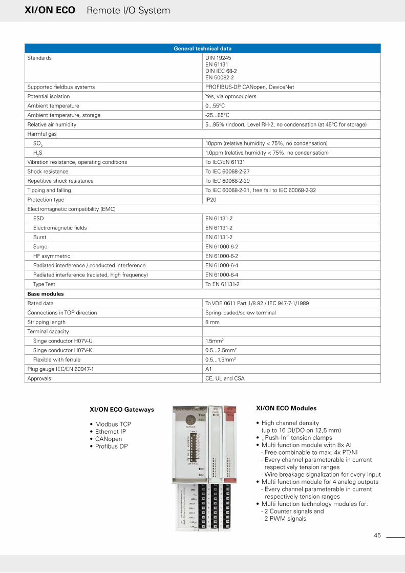
Analog Outputs XN-1AO-I(0/4...20MA) XN-2AO-I(0/4...20MA) XN-2AO-U(-10/0...+10VDC)
Channels No. 1 2
Nominal voltage on supply terminal UL 24 V DC
Nominal current drawn from supply terminal
IL mA ≤ 50
Nominal current drawn from module bus
IMB mA ≤ 39 ≤ 40 ≤ 43
Power loss W normally 1
Output voltage V DC - -10/0...+10
Output current mA 0/4...20 -
Load resistance
Resistive load O < 450 > 1000
Inductive load H < 0.001 -
Capacitive load µF - > 1
Short-circuit current mA - ≤ 40
Transmission frequency Hz ≤ 200 ≤ 200 ≤ 100
Offset error % ≤ 0.1
Linearity % 0.02 - 0.1
Basic error limit at 23 °C % < 0.2
Repetition accurancy (deviation) % 0.05 - 0.5
Output ripple % 0.02 - 0.02
Temperature coefficient 300 ppm/°C of full scale value
150 ppm/°C of full scale value
300 ppm/°C of full scale value
Recovery time
Resistive load ms 0.1 2 0.1
Inductive load ms 0.5 2 0.5
Capacitive load ms 0.5
RFI suppression - Common mode > 90 dBDifferential mode > 70 dBCross talk between chan-
nels > -50 dB
Measured value representation 16 Bit signed integer12 Bit full range flush-left
16 Bit signed integer12 Bit signed integer flush-
left12 Bit full range flush-left
Number of parameter bytes 3 3 (per channel)
Base modules
without C connection 2- / 3-wireXN-S3x-SBB
Article no. 140065 140146 140066
I/Oassistant
•Projectdesign/configuration•Parameterization/monitoring•Commissioning
XSoft-CoDeSys-2 – IEC 61131-3
•Programmingofthe XN-PLC-CANopen

61
Remote I/O SystemXI/ON
Technology Modules XN-1CNT-24VDCCounter module
Channels No. 1
Nominal voltage on supply terminal UL 24 V DC
Nominal current drawn from supply terminal
IL mA ≤ 50
Nominal current drawn from module bus
IMB mA ≤ 40
Power loss W < 1.3
Power supply of encoders Output voltage L+ (-0.8 V)Output current ≤ 0.5 A, short-circuit proof
Digital inputs
Input voltage
Input voltage nominal value V DC 24
Low signal UL -30 V DC...5 V DC
High signal UH 11 V DC...30 V DC
Input current
Low signal IL -8 mA...1.5 mA
High signal IH 2 mA...10 mA
Minimum pulse width µs Filter on: > 25 ms (20 kHz), Filter off: < 2.5 ms (200 kHz)
Digital Outputs
Output voltage
Output voltage nominal value V DC 24
Low signal UL ≤ 3 V DC
High signal ≥ L+ (-1 V)
Output current
High signal (permissible range) IH A 5 mA...2 A
High signal (nominal value) IH ≤ 0.5 A (55° C)
Switching frequency
With resistive load Hz 100
With inductive load Hz 2
with lamp load Hz ≤ 10
Lamp load RLL W ≤ 10
Output delay 100 µs (resistive load)
Short-circuit proof yes
Response threshold V 2.6...4 A
Inductive quenching L+ (-50...-60 V)
Measuring ranges
Frequency 0.1 Hz...200 kHz
Speed 1 rpm...25000 rpm
Period duration 5 ms...120 s
Counter modes
Signal evaluation A, B Pulse and direction, rotary encoder single/double/quadruple
Mode Endless, once only or periodic count
Hysteresis mm 0...255
Pulse durations 0...255
Synchronisation Once only / periodic
Count limits Upper count limit: 0...7FFF FFFFLower count limit: 8000 0000...FFFF FFFF
Measuring modes
Signal evaluation A, B Pulse and direction, rotary encoder single
Temperature coefficient ≤ 100 ppm/°C of full scale value
Number of diagnostics bits 1
Number of parameter bits 15
Base module
without C connection, for transmit-ter supply
4-wireXN-S4x-SBBS
Article no. 140069

www.eaton-automation.com
62
Remote I/O SystemXI/ON
Technology Modules XN-1RS232 XN-1RS485/422 XN-1SSI
Type RS 232 RS 484 / RS 422 SSI
Nominal voltage on supply terminal UL 24 V DC
Nominal current drawn from supply terminal
IL mA ≤ 25
Nominal current drawn from module bus
IMB mA ≤ 140 ≤ 90 ≤ 50
Power loss W normally 1
Transmission channels RxD, TxD, RTS, CTS RxD, TxD CL, D
Data buffer
Receive Byte 128 -
Transmit Byte 64 -
Connection type
RS 232 full-duplex -
RS 485 - 2-wire half-duplex -
RS 422 - 2-wire half-duplex or 4-wire full-duplex
4-wire full-duplex (clock output/signal input)
Bit transmission rate max. 115200 Bit/s (adjustable), default setting: 9600 Bit/s, 7 data bits, odd parity and 2 stop bits
max. 1 MHz (adjustable), default setting: 500 kBit/s
Insulation voltage
Between interface and module bus / system voltage
Vrms 500
Between interface and field voltage
Vrms 500
Common mode range V DC -7...12 -
Cable impedance O - 120
Bus termination - 120 Ω (external) internal
Cable length RS 232 m max. 15 max. 1000 max. 30
Number of diagnostics bits 1
Number of parameter bits 4
Base modules
without C connection 4-wireXN-S4x-SBBS
Article no. 140151 140152 140153
XI/ON technology modules:Interfaces and counters
The serial interface modules of the XI/ON range enable them to transfer serial data streams via the XI/ON system. This enables the connection of different devices such as printers, scanners or barcode readers with a serial RS232, RS485 or RS422 interface.
The XN-1SSI module allows the connection of encoders with an SSI inter-face, a supply voltage of 24 V DC (500 mA), a word length of up to 32 bits and a transmission rate of max. 1 MHz.
The XN-1CNT counter module detects normalized signals up to 200 kHz.

63
Remote I/O SystemXI/ON
Power Supply Modules XN-BR-24VDC-D XN-PF-24VDC-D XN-PF-120/230VAC-D
Operating voltage V DC 24 120 / 230 AC
System supply USYS V DC 24/5 -
Permissible range 24 V DC USYS V DC 18...30 -
Permissible range 5 V DC USYS V DC 4.7...5.3 -
Field voltage UL 24 V DC
Permissible range - nach EN 61131-2
Permissible range V DC 18...30 -
Nominal current drawn from module bus
IMB mA - ≤ 28 ≤ 25
Insulation test voltage Ui V AC - 1780
Ripple % < 5 (to EN 61131-2)
Maxmium operating current IEI A 10
Maximum system supply current IMB A 1.5 -
Number of diagnostics bits 4
Base modules without gateway supply
without C connection - 2-/3-wireXN-P3x-SBB
with C connection 4-wireXN-P4x-SBBC-B
4-wireXN-P4x-SBBC
Article no. 140071 140070 140072
11 21
12 22
13 23
14 24
Safety through coding
The pluggable design of the modu-les enable them to be exchanged quickly and without tools, even under live conditions (hot swapp-able). The mechanical coding prevents modules from being plugged incorrectly. The base modules of the XI/ON
standard systems are available with 2, 3 or 4-wire circuits and tension clamp or screw terminals. An additional terminal strip is unnecessary.
Related Documents


![Eaton CM-52 Remote Racking IL02400003E[3]](https://static.cupdf.com/doc/110x72/546050caaf79593a708b5223/eaton-cm-52-remote-racking-il02400003e3.jpg)