REMOTE DATA LOGGER WITH MULTI-SENSOR FOR GREENHOUSE LAM KHENG YIK A report submitted in partial fulfillment of the requirements for the award of the degree of Bachelor of Engineering (Electrical and Electronic) Faculty of Electrical and Electronic Engineering Universiti Malaysia Pahang JUNE 2012

Welcome message from author
This document is posted to help you gain knowledge. Please leave a comment to let me know what you think about it! Share it to your friends and learn new things together.
Transcript

REMOTE DATA LOGGER WITH MULTI-SENSOR FOR GREENHOUSE
LAM KHENG YIK
A report submitted in partial fulfillment of the requirements for the award of the
degree of Bachelor of Engineering (Electrical and Electronic)
Faculty of Electrical and Electronic Engineering
Universiti Malaysia Pahang
JUNE 2012

v
ABSTRACT
A data logger or a data acquisition system is an electronic device common in
measurement application. The basic form of data logger is to capture and store the
environment parameters over a period of time with incorporating sensors. This stand
alone device measure, collect and store data on the Secure Digital (SD) card.
Microcontroller is used in this system to perform the job. The system is equipped
with several sensors such as temperature, humidity, lights intensity and air
contaminants. The data can be analyzed in standard condition or using Personal
Computer (PC) for offline analysis and report. In the end, microcontroller Atmega32
system board is able to display four parameters from each sensor on Liquid Crystal
Display (LCD).

vi
ABSTRAK
Data logging atau data acquisition system adalah peranti elektronik yang
sama dalam pengukuran. Bentuk asas data logger adalah untuk mengambil dan
menyimpan parameter persekitaran sepanjang tempoh masa dengan sensor
menggabungkan. Peranti ini langkah pendirian sahaja, mengumpul dan menyimpan
data pada system ini untuk melaksanakan tugas. Sistem ini dilengkapi beberapa
sensor seperti suhi, kelembapan udara, intensity cahaya dan bahan cemar udara. Data
boleh dianalisis dalam keadaan standard atau menggunakan komputer peribadi (PC)
untuk analisis dan laporan data. Akhirnya, microcontroller Atmega32 system board
dapat menunjukkan bacaan daripada empat sensors berbeza dalam Liquid Crystal
Display (LCD).

vii
TABLE OF CONTENTS
CONTENT PAGE
TITLE PAGE i
DECLARATION ii
DEDICATION iii
ACKNOWLEDGEMENTS iv
ABSTRACT v
ABSTRAK vi
TABLE OF CONTENTS vii
LIST OF TABLES x
LIST OF FIGURES xii
LIST OF APPENDICES xv
CHAPTER 1: INTRODUCTION
1.1 Introduction 1
1.2 Problem Statement 3
1.3 Project Objectives 4
1.4 Project Scope 5
1.5 Thesis Outline 6
CHAPTER 2: LITERATURE REVIEW
2.1 Introduction 7
2.2 Previous Project Work 7

viii
2.2.1 8 Channel Configurable Data Logger for Reliability
Testing and Quality Assurance 8
2.2.2 Microcontroller Based Data Logger System 9
2.2.3 CAN Based Smart Sensor Network for Indoor Air
Quality Monitoring 10
2.2.4 Smart Wireless Temperature Data Logger Using IEEE
802.15.14/ZigBee Protocol 12
2.2.5 Development of an Indoor Environment Monitoring
System with Secure Digital (SD) Card Storage 14
2.2.6 A Simple Low Cost Data Acquisition System for Remote
Sensing of Relative Humidity and Temperature 15
2.2.7 SoSE Oriented Multipurpose Human-Data Acquisition
System Based on MEMS Sensors 17
2.3 Conclusion 18
CHAPTER 3: HARDWARE DESIGN
3.1 Hardware Overview 19
3.2 Microcontroller System 21
3.2.1 Power Supply Circuit 22
3.2.2 Reset Circuit 23
3.2.3 Clock Circuit 23
3.3 Sensor Module 24
3.3.1 Temperature and Humidity Sensor 24
3.3.2 Light Intensity Sensor 25
3.3.3 Air Contaminants Sensor 26
3.4 LCD Module 26
3.5 Real Time Clock Module 27
3.6 Keypad Module 28
3.7 XBEE Module 30
3.8 SD Card Module 30
CHAPTER 4: SOFTWARE DEVELOPMENT

ix
4.1 Introduction 32
4.2 Microcontroller System Testing 32
4.3 Sensor Module Testing 33
4.4 LCD Module Testing 36
4.5 Keypad Module Testing 37
4.6 Real Time Clock Module Testing 37
4.7 SD Card Module Testing 39
CHAPTER 5: TESTING AND RESULT
5.1 Introduction 41
5.2 Microcontroller System Testing 42
5.3 LCD Module Testing 43
5.4 Sensor Module Testing 45
5.5 Keypad Module Testing 53
CHAPTER 6: CONCLUSION AND RECOMMENDATION
6.1 Conclusion 55
6.2 Recommendation 55
6.3 Commercialisability 56
REFERENCES 57-60
APPENDIX A 61-71
APPENDIX B 72-75

x
LIST OF TABLES
TABLE NO. TITLE PAGE
3.1 Description of Data Bits for Keypad 29

xi
LIST OF FIGURES
FIGURE TITLE PAGE
2.1 Block diagram of the 8 channels data logger 8
2.2 Data Logger diagram consists of Master and Slave 10
2.3 Schematic of CAN application system 11
2.4 Block diagram for ZigBee transmitter 13
2.5 Block diagram for ZigBee receiver 13
2.6 Block diagram of indoor monitoring system 15
2.7 Linearizing circuit for sensing relative humidity 16
2.8 Linearizing network for temperature sensor 16
2.9 Block diagram for complete system 17
2.10 Block diagram of the prototype system 18
3.1 Schematic diagram of microcontroller Atmega32
System board 20
3.2 Block diagram of microcontroller board module 22
3.3 Power supply circuit 22
3.4 Reset circuit 23
3.5 Clock circuit 24
3.6 HSM-20G temperature and humidity sensors circuit 25
3.7 TSL 250R light intensity sensor circuit 25
3.8 TGS 2600 air contaminants sensor circuit 26
3.9 LCD circuit 27
3.10 Real time clock circuit 28
3.11 Keypad circuit 29
3.12 XBEE circuit 30

xii
3.13 SD card circuit 31
4.1 Flow chart of microcontroller module testing using LED
Blinking program 33
4.2 Flow chart of sensor module testing 35
4.3 Flow chart of LCD module testing 36
4.4 Flow chart of keypad module testing 37
4.5 Flow chart of real time clock module testing 38
4.6 Flow chart of SD card module testing 40
5.1 Microcontroller system testing program 42
5.2 LCD module testing program 43-45
5.3 Character display on LCD 45
5.4 Initial value for humidity sensor 46
5.5 Changes of air humidity for humidity sensor 47
5.6 Initial value for light intensity sensor 47
5.7 Changes of intensity for light intensity sensor 48
5.8 Temperature sensor testing program 49
5.9 Humidity sensor testing program 50
5.10 Light intensity sensor testing program 51
5.11 Air contaminants sensor testing program 52
5.12 Button 1 pressed on keypad 53
5.13 Button D pressed on keypad 54

xiii
LIST OF APPENDICES
APPENDIX TITLE PAGE
A Datasheet 61-71
B Schematic Circuit Diagram 72-75

CHAPTER 1
INTRODUCTION
1.1 Introduction
The usage of electronic device such as data logger has been growing rapidly. It
is a stand-alone device which is portable, small size, powered by battery and ability to
collect data on a 24-hour operation. The basic requirement for a data logging system is
acquisition, online analysis, logging, offline analysis, display and data sharing. Most
data loggers collect data which may be directly transferred to a computer. It is a very
common measurement application which can be programmed and record electrical
parameters over a period of time with a built in a sensor. Conversion of electrical
impulses from process instrument into digital data can be performed by using
microcontroller in order to record and store on the storage device for further analysis.
There are varieties of storage media option such as non-volatile memory, memory card,
floppy disks. Personal Computer (PC) based logging systems is very popular in
industrial, so mostly user will implement this system by using PC as their data storage
devices to store data on a local drive.
There are a lot of different data loggers in the market with various sensors. By
choosing desire parameters to be measured, input signals and number of inputs have to
be considered. It is usually economical. The advantages of data loggers are in terms of
ability to work at very long intervals, portable, reliability, flexibility and robustness.

2
Some of the criteria must be noted such as size, speed/memory, real time operation and
display. Smaller size is preferred depends on the purpose of usage. Speed is important
due to sampling rate from the changes of parameter. High memory offer capability to
record data for a longer interval. Time provided is important for user analysis based on
the data. All the parameter should be able to display on screen so user able to read the
readings.
A wide-spread operation of data logging system can be found from science
laboratory, hospital, manufacturing industries or weather stations. Due to independently
and sensitivity variation of parameters in data logger, it can be replaced human job to
measure parameter in a high risk situation. Furthermore, this system is equipped by
real-time information as well as capture historical data.

3
1.2 Problem Statement
How to sense indoor or outdoor air problems, temperature and humidity? By
solving this issue, it can be identified and possibly prevented with the help of data
loggers and sensors.
How to read the data after measured by data logger?
How to arrange the result that had been captured?

4
1.3 Project Objective
The aim of the project is to design a stand-alone microcontroller-based remote
data logger that able for measuring, monitoring and store the current parameters such as
temperature, light intensity, humidity and air contaminants in Secure Digital (SD) card.
The measured data will be stored in a memory card such as SD card at the
defined interval that issued by user in a actual format so it can be easily analyzed by the
user. At the same time, parameter measured from sensors will display readings on
Liquid Crystal Display (LCD).
The data will be stored into SD card and can be retrieved by using PC for
analysis.

5
1.4 Project Scope
In order to develop this system, a prototype should be prepared. In order to
accomplish it, scope of the project is summarized as follow:
Develop an 8-bit microcontroller Atmega32 as the main controller for the
system
Design sensor circuits for temperature, humidity, light intensity and air
contaminants
Develop a LCD module for display information
Design a Real Time Clock (RTC) for real-time parameter and 4x4 matrix
keypad to keep track and update from time to time
Develop a SD memory card for data media storage
Develop a Microsoft Visual Basic (VB) program for read SD card and offline
analysis

6
1.5 Thesis Outline
This thesis will consist of six chapters. Every chapter details will elaborate as
below.
Chapter 1 gives a brief overview of the project. Objectives and scope of project
also stated here to provide guideline in this chapter.
Chapter 2 involves literature review. The review of previous research papers
such as AVR microcontroller module, sensors module, LCD display module, keypad
module, ZigBee module and real time clock module are included here.
Chapter 3 discusses the methodology of this project. Hardware and software
implementation are included in this chapter too. The discussion is based on flow chart
of the system.
Chapter 4 contains the testing result and the discussion of the testing will
conducted.
Chapter 5 will indicates the recommendation for future development. Besides,
the conclusion of the outcome of the project included as well.

CHAPTER 2
LITERATURE REVIEW
2.1 INTRODUCTION
Literature review is a previous researches and studies contributed according to
data logger and related field. It plays pivotal role in developing in order to study
contributed work. Several papers and journals are reviewed in order to produce the
ultimate design. Relevant researcher works to the project will be discussed in details.
2.2 Previous Project Work
Data logger is a stand-alone device which plays an important role especially in
industries. It has become more flexibility and convenient because it helps in the
situation where the information changes faster than a human can possibly collect. The
following researchers topics will discussed in details below.
8
2.2.1 8 Channel Configurable Data Logger for Reliability Testing and Quality
Assurance
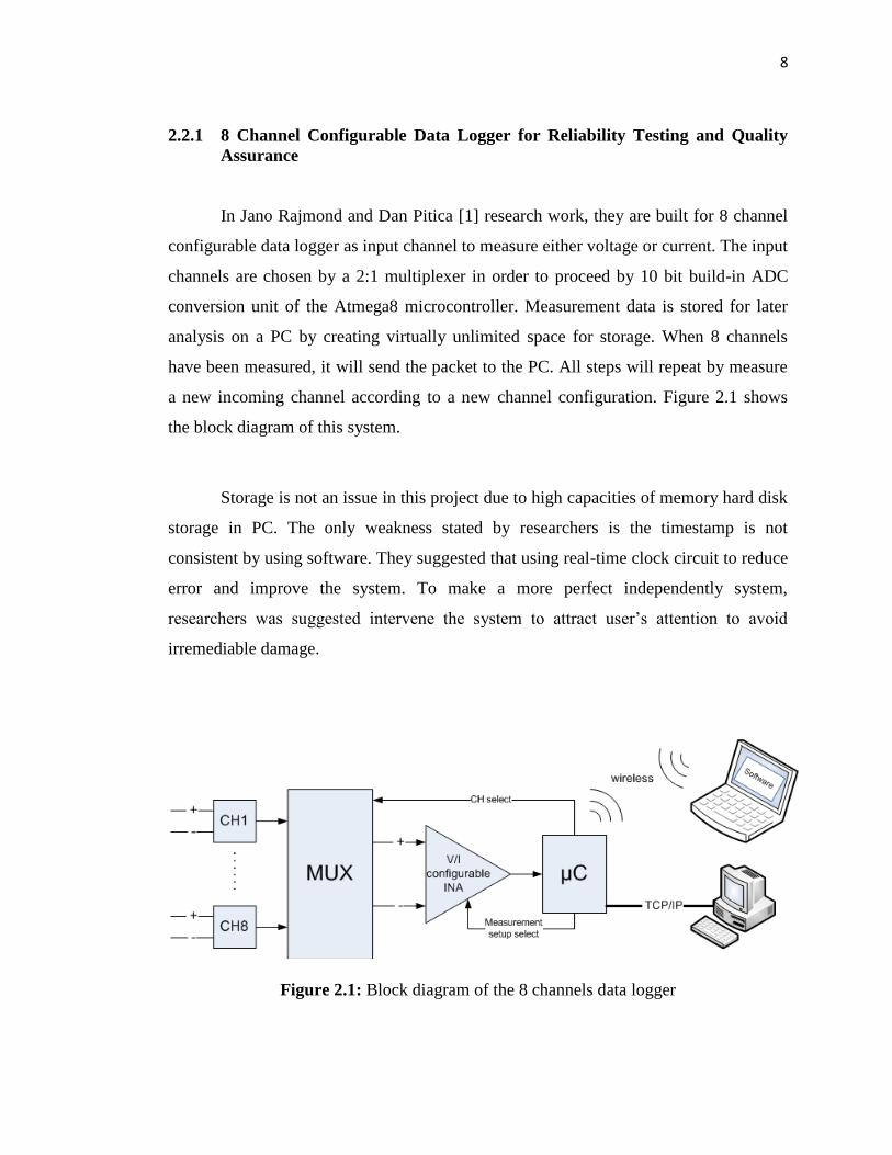
In Jano Rajmond and Dan Pitica [1] research work, they are built for 8 channel
configurable data logger as input channel to measure either voltage or current. The input
channels are chosen by a 2:1 multiplexer in order to proceed by 10 bit build-in ADC
conversion unit of the Atmega8 microcontroller. Measurement data is stored for later
analysis on a PC by creating virtually unlimited space for storage. When 8 channels
have been measured, it will send the packet to the PC. All steps will repeat by measure
a new incoming channel according to a new channel configuration. Figure 2.1 shows
the block diagram of this system.
Storage is not an issue in this project due to high capacities of memory hard disk
storage in PC. The only weakness stated by researchers is the timestamp is not
consistent by using software. They suggested that using real-time clock circuit to reduce
error and improve the system. To make a more perfect independently system,
researchers was suggested intervene the system to attract user’s attention to avoid
irremediable damage.
Figure 2.1: Block diagram of the 8 channels data logger
9
2.2.2 Microcontroller based Data Logger System
The senior students of Information Technical Division Engineering at
Soonchunhyang University [2] built their project by using microcontroller Atmega128.
Atmega128 supported several features in their project such as transparent D-latch,
SRAM chip and RS-232 chip. Transparent D-latch is cooperating with SRAM module
in order to demultiplexing address/data channels from the Atmega128. In RS-232
module, it is function as serial communication between Atmega128 with PC.
Master/slave function applied in this project. They used BIM-418-F as their RF
module to wirelessly transmit and receive the signal. In master circuit, they designed
main device of RS-232 module and RF module. However, slave circuit consists of RF
module, LCD and power module. The parameters from sensors will be sending from
master to slave circuit through RF module and display on LCD. Data transmission will
be used half duplex method at speeds 40k bit/sec within distance of 30 meters in the
building.

10
Figure 2.2: Data logger diagram consists of Master and Slave
2.2.3 CAN Based Smart Sensor Network for Indoor Air Quality Monitoring
Minu A Pillai, Sridevi Veerasingam and Taswanth Sai D [3] successfully built
an indoor air quality monitoring system by using controller Area Network (CAN). CAN
is a based on smart sensor network. It can provide an ideal platform for interconnecting
nodes and allows each node to communicate with any other nodes.
CAN based smart sensor network developed with two transmitter nodes and one
receiver nodes. Two transmitter nodes consist of air contaminants sensor (TGS 2600)
and volatile of organic solvents sensor (TGS 2620) to measure sensitivity concentration
in the air. For receiver node, motor control is the node which is activated or deactivates
the fan to control indoor air quality.

11
When the system begins, both sensors will start measuring air quality based on
its own function. Analog data from sensors will send to AT89C51CC03 microcontroller
by using inbuilt ADC which is converting from analog to digital form. Then,
microcontroller will give out digitally output to CAN transceiver so CAN used to
communicate between two sensor nodes and motor control node. CAN bus interface
with the sensors will transmit to the motor control node which is received by another
CAN bus. If the data received is higher than defined limit, motor will activate the fan
and it will start to rotate continuously. Figure 2.3 shows the overall CAN application
system that has been proposed.
Figure 2.3: Schematic of CAN application system
12
2.2.4 Smart Wireless Temperature Data Logger Using IEEE 802.15.14/ZigBee
Protocol
Four researchers Vivek Kumar Sehgal, Nitin, Durg Singh Chauhan and Rohin
Sharma [4] have developed a temperature data logger system by using IEEE 802.15.4
ZigBee protocol. They are used 8 bit microcontroller 89C51 and temperature sensor
LM35-DZ. This sensor is operating from range 0 degree Celsius to 100 degree Celsius.
The measured parameter will be proceeds by ADC from microcontroller. There will be
conversion data from analog form to digital form by ADC then microcontroller will
transmit the data digitally through ZigBee module which is send to an assigned receiver.
Another module assigned as receiver will receives the data and display on LCD. In
same spot, RS-232 will transmit the data to the PC for monitoring and analysis.
During the process in this system, researchers faced some challenges. They
found out if ZigBee module placed in a long range distance between transmitter and
receiver, there will be error occurred. In order to solve the issue and make this system to
be more perfect, researchers has been suggested that is built a memory database by
using chip memory and connected remotely to the PC through wireless link. Besides,
they also stated system can be more stable and efficiency by using PID control
algorithm. In future work, they will build their system to compatible with different
network protocols. Figure 2.4 shows the block diagram of ZigBee transmission and
Figure 2.5 shows the block diagram of ZigBee receiver.

13
Figure 2.4: Block diagram for ZigBee transmitter
Figure 2.5: Block diagram for ZigBee receiver

14
2.2.5 Development of an Indoor Environment Monitoring System with Secure
Digital (SD) Card Storage
The most important for monitoring system is the need to store the results in
memory storage for future graph analysis. Most of the systems have chosen to store into
PC due to its unlimited memory. Some of the researchers prefer to store the parameters
into Electrically Erasable Programmable Read-Only Memory (EEPROM) memory chip.
However, for researchers Cheng Wei Peh, Vee Khee Wong and Ying Khai [5], they
have chosen SD card in their system as memory storage. the block diagram of indoor
monitoring system is shown in Figure 2.6.
The main purpose in this system is to develop a monitoring environment
variation system. They are using 8-bit PIC18F4620 microcontroller with external
crystal 10MHz act as a main controller system following by some module such as
sensors, LCD and SD card. LCD will be display parameter from sensors via RS232 port.
The main circuit is using LM7805 voltage regulator to generate 5V which is compatible
to microcontroller, sensors and LCD.
SD card is operating under Serial Peripheral Interface (SPI) mode. The library
file of microcontroller is used to provide an interface to File Allocation Table (FAT)-12
and FAT-16. By using Java program which is Graphical User Interface (GUI), it can
allowed to access and analyze data file recorded in the SD card.
Researchers stated that the microcontroller used in this system is not sufficient
that expected due to insufficient of the remaining memory space to apply in other
system function. Master Synchronous Serial Port (MSSP) in microcontroller cannot be
use simultaneously between I2C and SPI; it can only choose one feature to function in
one time. In this reason, Real Time Clock (RTC) which is using I2C feature to provide
accurate timing information affected. If the system using SPI feature for SD card for
storage purpose, it is impossible to use I2C in the same time. In order to solve this

15
problem, researchers suggested that system can upgrade by using bit banging method
from programming effort.
Figure 2.6: Block diagram of indoor monitoring system
2.2.6 A Simple Low Cost Data Acquisition System for Remote Sensing of
Relative Humidity and Temperature
The researchers have presented a simple technique in combining analog circuit
and digital circuit theory together with programming technique to control the hardware
for remote sensing of temperature and relative humidity. In Figure 2.7 as shown, a
capacitance relative humidity sensor was used in order to converts this capacitance into
voltage proportional to relative humidity. In temperature sensor, thermistor Bridge with
Whetstone is used and produce a differential output voltage changed with temperature
changes. Figure 2.8 shows the linearizing network for temperature sensor. All these
Related Documents


![Lava lwvW Lavaa. soohee mehulaa 4 sUhI mhlw 4 ] Soohee, Fourth Mehl:](https://static.cupdf.com/doc/110x72/56649d185503460f949ed955/lava-lwvw-lavaa-soohee-mehulaa-4-suhi-mhlw-4-soohee-fourth-mehl.jpg)