T24-RDC Remote Data Collection User Manual mantracourt.com

Welcome message from author
This document is posted to help you gain knowledge. Please leave a comment to let me know what you think about it! Share it to your friends and learn new things together.
Transcript

T24-RDC Remote Data Collection User Manual mantracourt.com
Mantracourt Electronics Limited T24-RDC User Manual 1
Introduction / Overview ............................................................................... 3 T24 Topology Overview ............................................................................... 3 LEDs ..................................................................................................... 4 Connections ............................................................................................ 5 Installation ............................................................................................. 5
T24 Toolkit ........................................................................................... 5 T24-BSu Base Station ............................................................................... 5
T24 Toolkit ............................................................................................. 6 General Pages ....................................................................................... 6
Setup Base Station Communications ........................................................... 6 Home ............................................................................................... 7 Analyser ............................................................................................ 8 Information ........................................................................................ 9 Channel and Encryption ........................................................................ 10 Save and Restore ................................................................................ 11 System Settings ................................................................................. 12 Inputs ............................................................................................. 21 Data Collection .................................................................................. 23
CSV File Format ............................................................................... 23 SMS Reports ...................................................................................... 30
SMS Configuration ............................................................................ 32 Triggered Reports ............................................................................... 33
Tokens .................................................................................................. 38 Tokens .............................................................................................. 38 Time Date Formatting ............................................................................ 39
Destinations............................................................................................ 41 Email .................................................................................................. 41 SMS Message .......................................................................................... 41 FTP .................................................................................................... 41 TCP Socket (NOT YET IMPLEMENTED) ............................................................ 41 HTTP Post ............................................................................................ 42
Digital Input ............................................................................................ 43 Alarm Output .......................................................................................... 43 Installation ............................................................................................. 44
Overview .............................................................................................. 44 Battery Life ............................................................................................ 45
Scenario 1 .......................................................................................... 45 Scenario 2 .......................................................................................... 46
SIM Card Considerations ............................................................................. 47 Key Tariff Features:................................................................................. 47
Pay As You Go ..................................................................................... 47 Contract ............................................................................................ 47
Service Provider Settings for T24-RDC ........................................................... 47 Service Providers .................................................................................... 47 Service Provider Connection Details .............................................................. 48
Simple Mail Transfer Protocol (SMTP) Servers .................................................. 49 SMTP Server Options ................................................................................ 49
Mobile Service Provider SMTP Servers ......................................................... 49 Other “Free” SMTP Servers ...................................................................... 49 Your SMTP server .................................................................................. 49 Web Based Relaying SMTP server ............................................................... 49
Mantracourt Electronics Limited T24-RDC User Manual 2
SMTP Server Providers .............................................................................. 49 Specifications .......................................................................................... 50
General Radio ........................................................................................ 50 T24-RDC ............................................................................................... 50 Physical Dimensions ................................................................................. 50
Approvals ............................................................................................... 51 CE ...................................................................................................... 51 FCC .................................................................................................... 51 Industry Canada ..................................................................................... 52
OEM / Reseller Marking and Documentation Requirements .................................. 52 FCC .................................................................................................... 52 IC ...................................................................................................... 52 CE ...................................................................................................... 52
Declaration of Conformity .......................................................................... 54 Worldwide Regional Approvals ..................................................................... 55
Important Note .................................................................................... 55 Warranty ............................................................................................... 55
Mantracourt Electronics Limited T24-RDC User Manual 3
Introduction / Overview The T24-RDC collects data from remote T24 acquisition modules and generates CSV files, custom SMS reports and triggered reports that are delivered over the cellular GPRS network and GSM network for SMS messaging. You can either define the active group of remote acquisition modules or allow the device to work automatically, adding new modules as it detects them. The main logging functionality is to collect data from the remote modules and place the results into a CSV file. You can specify the amount of data stored in the CSV file by setting the age of data it contains. You can also specify at what interval the CSV file is delivered to up to 3 destinations which can be an email address, SMS phone number, FTP server, raw socket or delivered as an HTTP POST to a web server. This allows a very flexible level of control over what data is reported and when. For example, you may want to collect and report only 24 hours worth of data at a time or possibly collect data over one month but still report 1 months worth of data weekly. SMS reports can be user designed to deliver the data values from specific devices and be triggered by sending an SMS message to the device. Up to 10 SMS reports can be designed. The remote devices can be referenced either by channel number or data tag. These reports are always sent back to the phone that triggered the message. Up to 20 triggered reports can be user designed that can look for individual devices exceeding limits, reporting errors or local events such as loss of external power and lid open, or even just at set intervals. These alerts can deliver a custom message (that can refer to the channels and values that caused the error) to an email address, SMS phone number, FTP server, raw socket or delivered as an HTTP POST to a web server. (Note: a single alert can be defined to cover a range or all devices but in this case individual values cannot be reported, just the fact that channels 1,3,4-8 have exceeded set limits etc.) SMS messaging may also be used to change or update certain user parameters of the device. i.e. You may change a delivery destination of a report or change the interval of reporting. This saves on costly site visits for minor operational changes. The device has an internal Li-On battery which can act as battery backup, or in low power mode, may power the device for the required period of operation. An external power supply can increase the operation periods and may be a permanent supply or batteries. The internal battery is recharged by the external power supply. There are three operational modes: Normal, Low Power and Ultra Low Power. In normal mode incoming SMS messages are processed as they are received and triggered reports are checked in real time. In low power mode the whole device sleeps between captures so cannot act on incoming SMS messages or triggered reports until it next wakes at the log interval. In Ultra Low Power mode the SMS reports and triggered reports are not actioned until the CSV data send interval. The RDC is a Remote Data Collection device which communicates using GSM/GPRS and therefore is bound by the restrictions and limitations of a mobile data network. This can include but is not limited to partial or complete loss of coverage, environmental interference or network faults.
T24 Topology Overview The T24-RDC uses data delivered from T24 acquisition modules. Acquisition modules usually operate in low power mode where they sleep for most of the time and wake briefly to take a measurement and to transmit the data. Each T24 device had a unique 6 character hexadecimal ID which the T24 Toolkit uses to communicate with and to configure the device. The acquisition modules generate data which is identified by Data Tags which are 4 character hexadecimal codes. The default Data Tag of a T24 module is the last 4 characters of its ID but this can be changed using the toolkit. i.e. A device with an ID of FFC12A would have a default Data Tag of C12A. The T24-RDC only needs to know the Data Tag of the acquisition modules it is required to collect data from. The module can even be configured to automatically collect data from any module it receives data from.
Mantracourt Electronics Limited T24-RDC User Manual 4
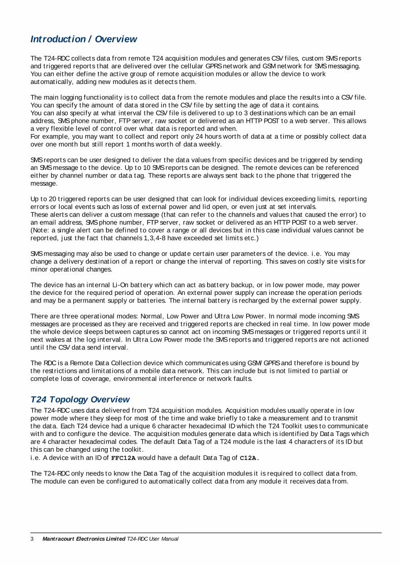
LEDs
Mode
T24 Activity
Network Activity
T24 Error
Network Error
SIM Error LEDs indicate: During Startup Awake Asleep (Low Power Modes) Mode Remains off Flashes 2 X per second
Flashes briefly 1 X per second
T24 Activity Flashes when T24 data packets are received
Network Activity Remains off Lights when communicating with cellular network
Remains off
T24 Error Flashes Lights when no T24 data present for longer than user defined timeout period
Flashes briefly 1 X per second to indicate no T24 data present for longer than user defined period
Network Error Flashes Lights to indicate failure to connect to cellular network (flashes fast to indicate a reconnection in progress)
Flashes briefly 1 X per second to indicate last attempt at connecting to cellular network failed
SIM Error Remains off The SIM is missing, is PIN protected or PUK locked
Flashes briefly 1 X per second to indicate the SIM is missing, is PIN protected or PUK locked
The startup mode can take up to a couple of minutes while cellular network connection is achieved. Startup will commence after the Reset Button is pressed or power is first applied. During startup the Mode LED will remain off. If there is a problem with the onboard T24 radio or the cellular network module then either the T24 Error LED or the Network Error LED will remain lit while the Mode LED flashes and the module will be inoperable. Pressing the Pair/Reset switch will reset and try the connections again. If after applying power or pressing the Reset button the unit detects a problem with the internal real time clock the LEDs will all go out. The unit will reset and try again a few seconds later causing all LEDS to flash on. If this state persists you should remove the battery connector and any external power supply for a few seconds then re-attach. Ph
Mantracourt Electronics Limited T24-RDC User Manual 5
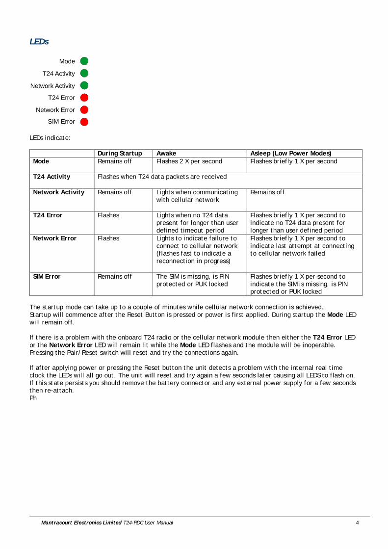
Connections On receipt of the module it may be necessary to connect the battery cable to the connector. Take care that the correct polarity is observed. Usually an external power supply will be required. This is connected to the connector marked ‘External Power’ and can be from 9V to 32V dc and able to supply 450mA. Ensure correct polarity is observed.
External Power
RTC BackupBattery
Pair/Reset
As soon as power is supplied the module will enter its startup routine. The above diagram also shows where to connect the digital input and the alarm output. See later in the manual for more information on digital IO.
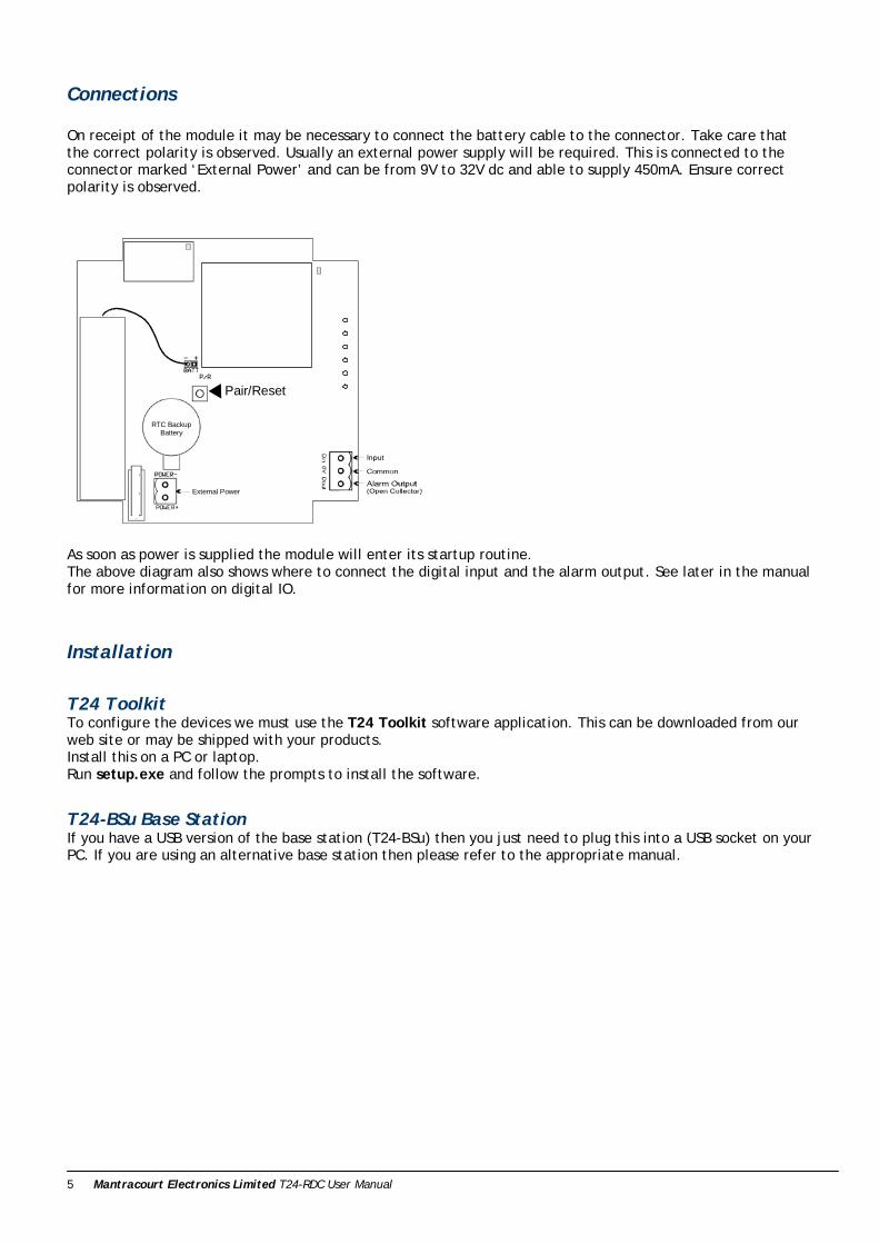
Installation
T24 Toolkit To configure the devices we must use the T24 Toolkit software application. This can be downloaded from our web site or may be shipped with your products. Install this on a PC or laptop. Run setup.exe and follow the prompts to install the software.
T24-BSu Base Station If you have a USB version of the base station (T24-BSu) then you just need to plug this into a USB socket on your PC. If you are using an alternative base station then please refer to the appropriate manual.
Mantracourt Electronics Limited T24-RDC User Manual 6
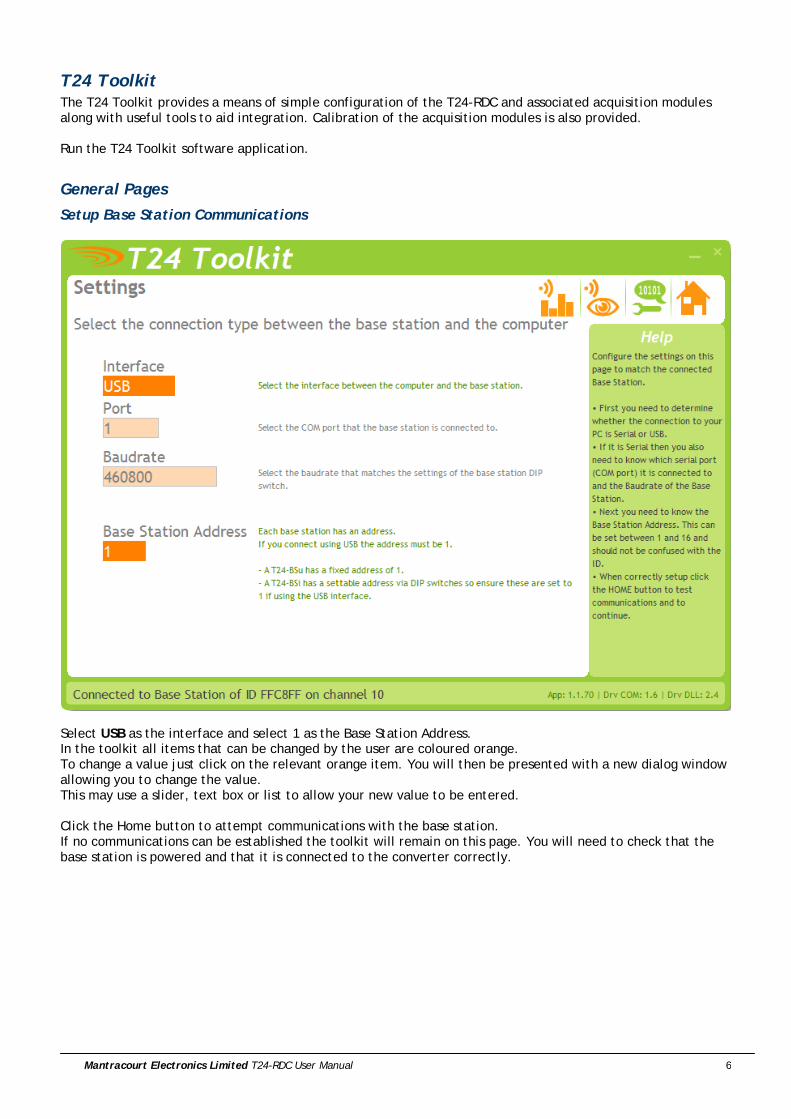
T24 Toolkit The T24 Toolkit provides a means of simple configuration of the T24-RDC and associated acquisition modules along with useful tools to aid integration. Calibration of the acquisition modules is also provided. Run the T24 Toolkit software application.
General Pages
Setup Base Station Communications
Select USB as the interface and select 1 as the Base Station Address. In the toolkit all items that can be changed by the user are coloured orange. To change a value just click on the relevant orange item. You will then be presented with a new dialog window allowing you to change the value. This may use a slider, text box or list to allow your new value to be entered. Click the Home button to attempt communications with the base station. If no communications can be established the toolkit will remain on this page. You will need to check that the base station is powered and that it is connected to the converter correctly.
Mantracourt Electronics Limited T24-RDC User Manual 7
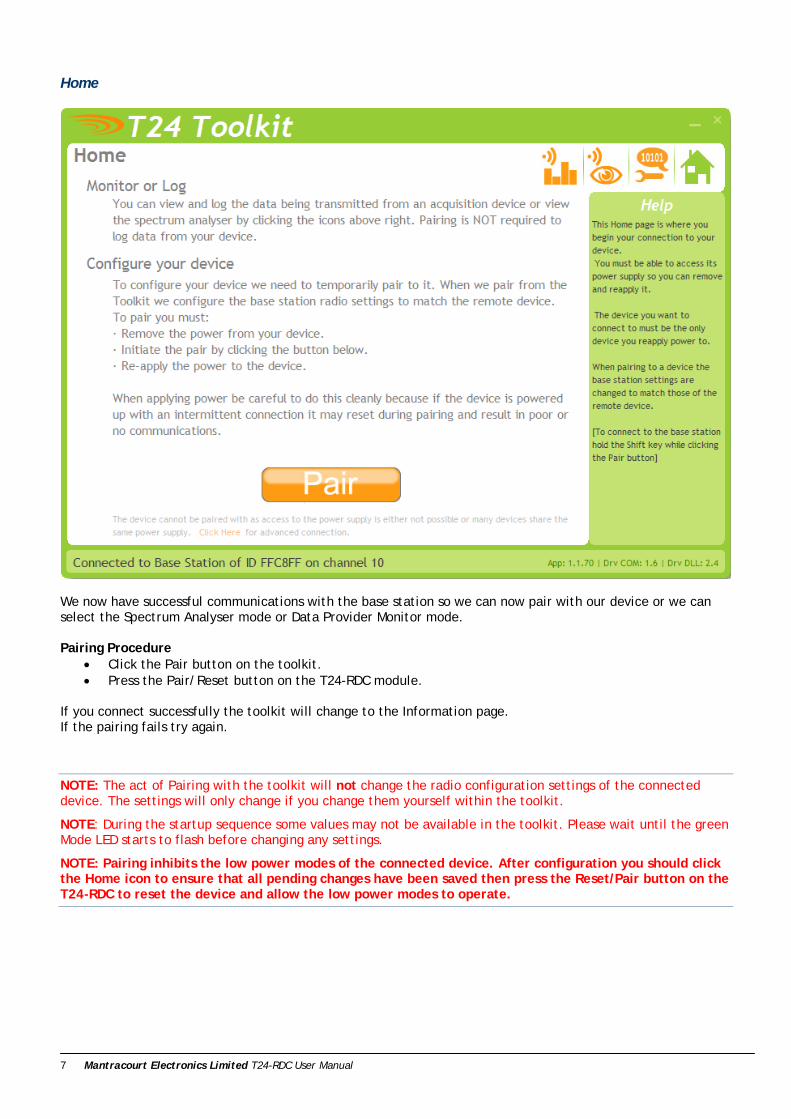
Home
We now have successful communications with the base station so we can now pair with our device or we can select the Spectrum Analyser mode or Data Provider Monitor mode. Pairing Procedure
• Click the Pair button on the toolkit. • Press the Pair/Reset button on the T24-RDC module.
If you connect successfully the toolkit will change to the Information page. If the pairing fails try again.
NOTE: The act of Pairing with the toolkit will not change the radio configuration settings of the connected device. The settings will only change if you change them yourself within the toolkit.
NOTE: During the startup sequence some values may not be available in the toolkit. Please wait until the green Mode LED starts to flash before changing any settings.
NOTE: Pairing inhibits the low power modes of the connected device. After configuration you should click the Home icon to ensure that all pending changes have been saved then press the Reset/Pair button on the T24-RDC to reset the device and allow the low power modes to operate.
Mantracourt Electronics Limited T24-RDC User Manual 8
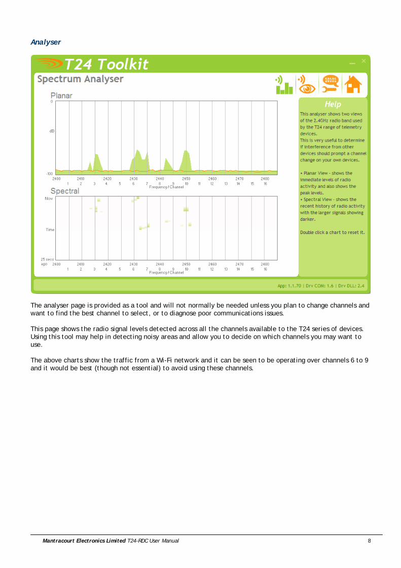
Analyser
The analyser page is provided as a tool and will not normally be needed unless you plan to change channels and want to find the best channel to select, or to diagnose poor communications issues. This page shows the radio signal levels detected across all the channels available to the T24 series of devices. Using this tool may help in detecting noisy areas and allow you to decide on which channels you may want to use. The above charts show the traffic from a Wi-Fi network and it can be seen to be operating over channels 6 to 9 and it would be best (though not essential) to avoid using these channels.
Mantracourt Electronics Limited T24-RDC User Manual 9
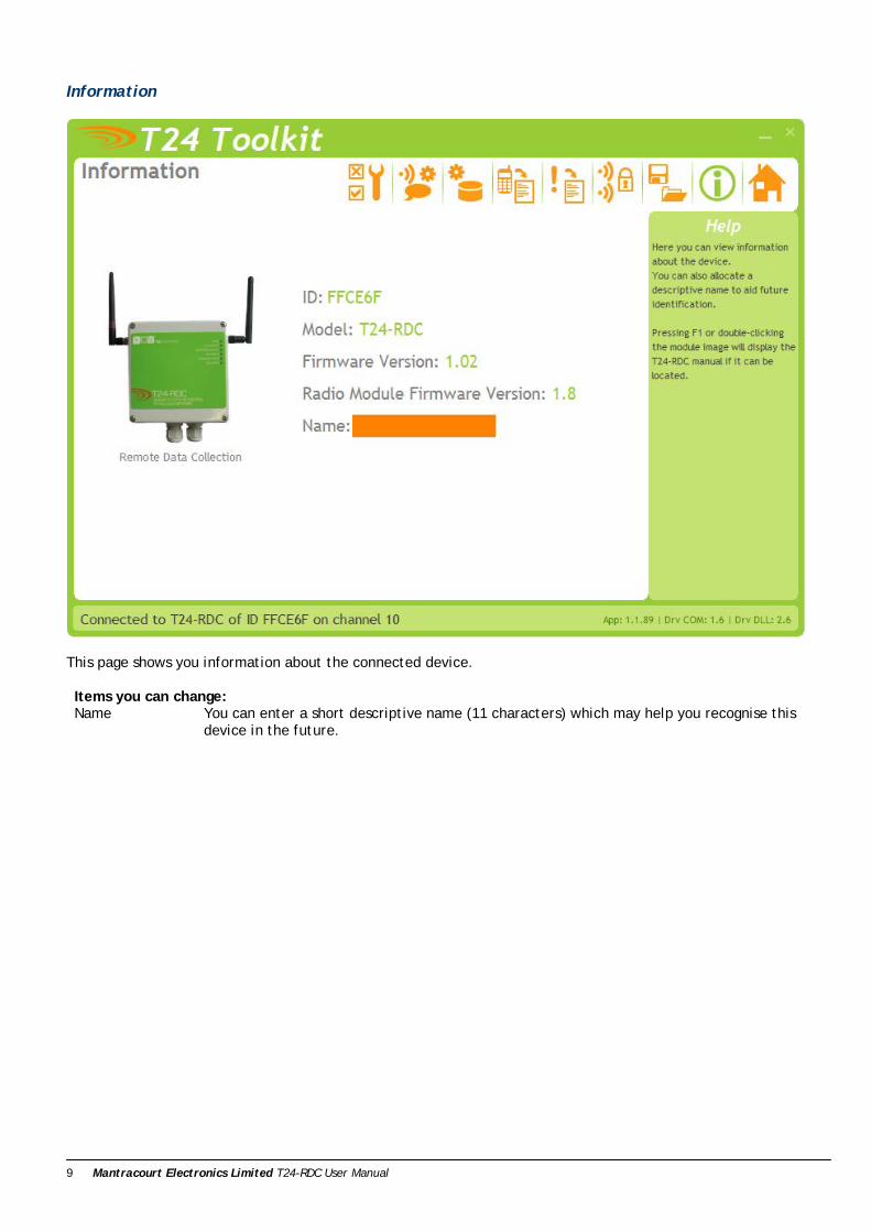
Information
This page shows you information about the connected device. Items you can change: Name You can enter a short descriptive name (11 characters) which may help you recognise this
device in the future.
Mantracourt Electronics Limited T24-RDC User Manual 10
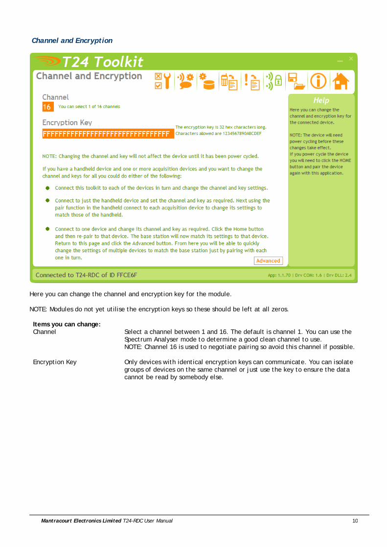
Channel and Encryption
Here you can change the channel and encryption key for the module. NOTE: Modules do not yet utilise the encryption keys so these should be left at all zeros. Items you can change: Channel Select a channel between 1 and 16. The default is channel 1. You can use the
Spectrum Analyser mode to determine a good clean channel to use. NOTE: Channel 16 is used to negotiate pairing so avoid this channel if possible.
Encryption Key Only devices with identical encryption keys can communicate. You can isolate groups of devices on the same channel or just use the key to ensure the data cannot be read by somebody else.
Mantracourt Electronics Limited T24-RDC User Manual 11
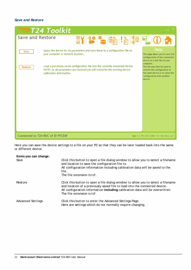
Save and Restore
Here you can save the device settings to a file on your PC so that they can be later loaded back into the same or different device. Items you can change: Save Click this button to open a file dialog window to allow you to select a filename
and location to save the configuration file to. All configuration information including calibration data will be saved to the file. The file extension is tcf.
Restore Click this button to open a file dialog window to allow you to select a filename and location of a previously saved file to load into the connected device. All configuration information including calibration data will be overwritten. The file extension is tcf.
Advanced Settings Click this button to enter the Advanced Settings Page. Here are settings which do not normally require changing.
Mantracourt Electronics Limited T24-RDC User Manual 12
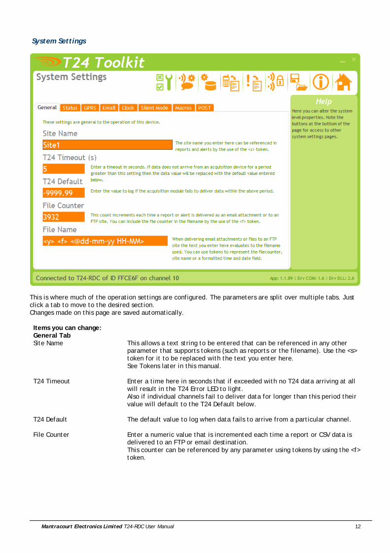
System Settings
This is where much of the operation settings are configured. The parameters are split over multiple tabs. Just click a tab to move to the desired section. Changes made on this page are saved automatically. Items you can change: General Tab Site Name This allows a text string to be entered that can be referenced in any other
parameter that supports tokens (such as reports or the filename). Use the <s> token for it to be replaced with the text you enter here. See Tokens later in this manual.
T24 Timeout Enter a time here in seconds that if exceeded with no T24 data arriving at all will result in the T24 Error LED to light. Also if individual channels fail to deliver data for longer than this period their value will default to the T24 Default below.
T24 Default The default value to log when data fails to arrive from a particular channel.
File Counter Enter a numeric value that is incremented each time a report or CSV data is delivered to an FTP or email destination. This counter can be referenced by any parameter using tokens by using the <f> token.
Mantracourt Electronics Limited T24-RDC User Manual 13
File Name You can set the filename text to use whenever a file is delivered to an FTP server (Either reports or the CSV data) or to an email address (CSV data). The filename is common to all but you can make use of tokens to make each file unique. Do not specify an extension. CSV data will be allocated a .CSV extension and reports will be allocated a .TXT extension. Useful tokens include <s>, <y>, <f> and <@xxx> date time formatted tokens.
Mantracourt Electronics Limited T24-RDC User Manual 14
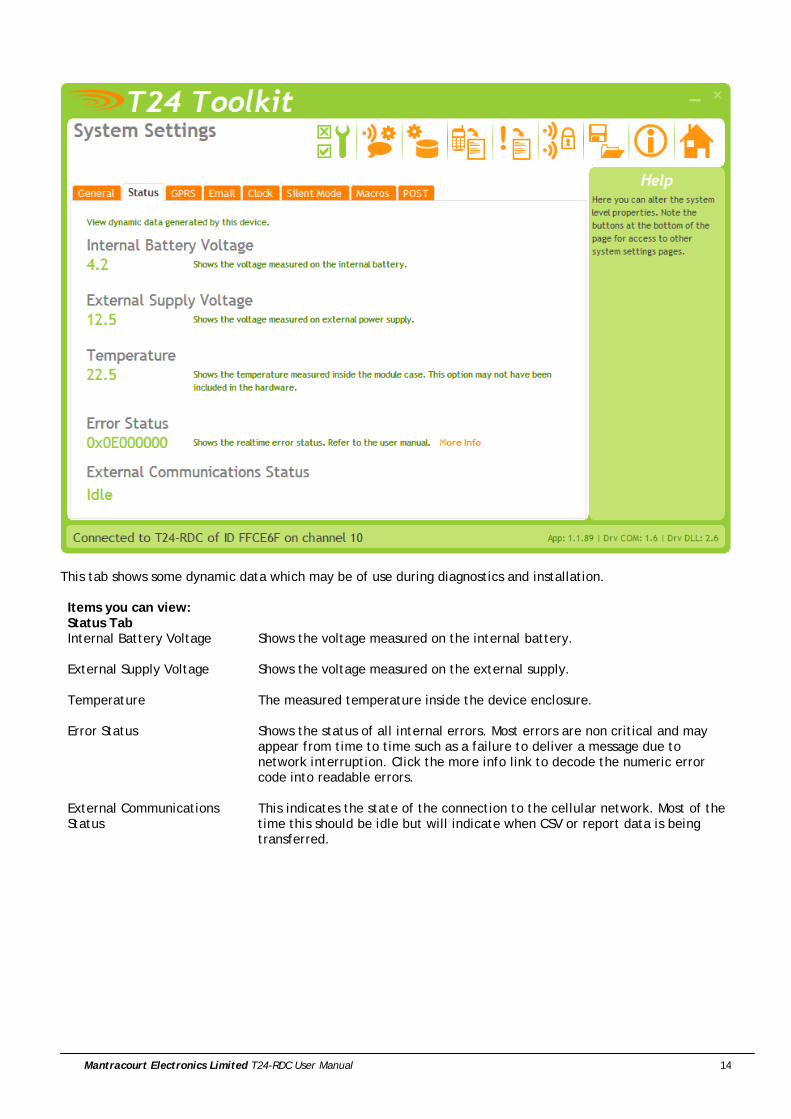
This tab shows some dynamic data which may be of use during diagnostics and installation. Items you can view: Status Tab Internal Battery Voltage Shows the voltage measured on the internal battery.
External Supply Voltage Shows the voltage measured on the external supply.
Temperature The measured temperature inside the device enclosure.
Error Status Shows the status of all internal errors. Most errors are non critical and may
appear from time to time such as a failure to deliver a message due to network interruption. Click the more info link to decode the numeric error code into readable errors.
External Communications Status
This indicates the state of the connection to the cellular network. Most of the time this should be idle but will indicate when CSV or report data is being transferred.

Mantracourt Electronics Limited T24-RDC User Manual 15
The settings here apply to the GPRS network and affect the delivery to FTP, email and sockets. Items you can change or view: GPRS Tab ISP APN Enter the Access Point Name for your SIM card provider. This information will
be available from your ISP or SIM supplier.
ISP Username Enter the username required by your ISP.
ISP Password Enter the password required by your ISP.
My Number Shows the telephone number of the T24-RDC module. Use this number to send SMS messages to the device.
Signal Strength This indicates the strength of the network signal and is shown only on connection and is not dynamically updated. You will need to wait until the module has completed its startup routine before this value is displayed.

Mantracourt Electronics Limited T24-RDC User Manual 16
To send email the module requires an SMTP server. You may have a company server through which mail may be relayed or you may use another service provider or possibly the provider of the SIM card. Items you can change: Email Tab SMTP Server Name Enter the host name of the SMTP server. This may be an IP address or a DNS
name.
SMTP Username Enter the username required by your SMTP server.
SMTP Password Enter the password required by your SMTP server.
Email From Enter the email address from which all emails are to appear to have been sent by. NOTE: some SMTP servers may require a certain email address here to enable using their service.
Email Subject Enter a subject to appear in the email subject line. This is common for all delivered email both CSV data and reports so would usually indicate the site from which the module operates.
Mantracourt Electronics Limited T24-RDC User Manual 17
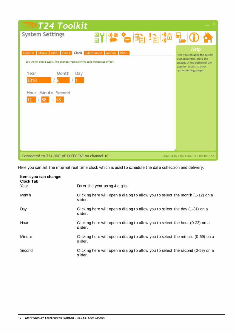
Here you can set the internal real time clock which is used to schedule the data collection and delivery. Items you can change: Clock Tab Year Enter the year using 4 digits.
Month Clicking here will open a dialog to allow you to select the month (1-12) on a
slider.
Day Clicking here will open a dialog to allow you to select the day (1-31) on a slider.
Hour Clicking here will open a dialog to allow you to select the hour (0-23) on a slider.
Minute Clicking here will open a dialog to allow you to select the minute (0-59) on a slider.
Second Clicking here will open a dialog to allow you to select the second (0-59) on a slider.
Mantracourt Electronics Limited T24-RDC User Manual 18
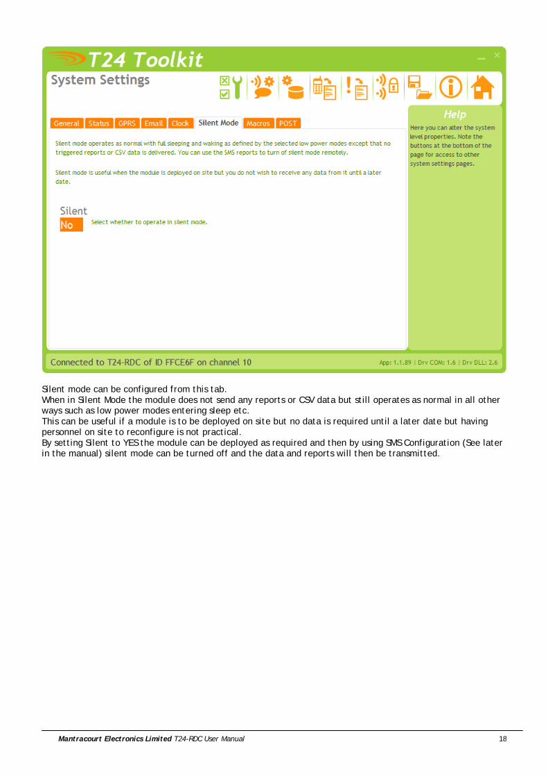
Silent mode can be configured from this tab. When in Silent Mode the module does not send any reports or CSV data but still operates as normal in all other ways such as low power modes entering sleep etc. This can be useful if a module is to be deployed on site but no data is required until a later date but having personnel on site to reconfigure is not practical. By setting Silent to YES the module can be deployed as required and then by using SMS Configuration (See later in the manual) silent mode can be turned off and the data and reports will then be transmitted.

Mantracourt Electronics Limited T24-RDC User Manual 19
Macros are discrete pieces of text that can be referenced by other parameters that support tokens. This is useful for a number of reasons.
• Reports have a finite size so you could increase the size of the raw report by referencing macros. • Some information is required in multiple reports. By entering it once in a macro and referencing it in
multiple reports it saves on typing. • Also a macro can be changed by remote SMS configuration (whereas an entire report body cannot) so
altering support information delivered in a report could be altered remotely. Items you can change: Macro Tab Macro 1 Enter the text to substitute for the token <m1>
Macro 2 Enter the text to substitute for the token <m2>
Macro 3 Enter the text to substitute for the token <m3>
Macro 4 Enter the text to substitute for the token <m4>
Macro 5 Enter the text to substitute for the token <m5>
Macro 6 Enter the text to substitute for the token <m6>

Mantracourt Electronics Limited T24-RDC User Manual 20
When you post data to a web site or service there may be security in place. Sometimes your data can be authenticated by adding a key to the data content of the post but sometimes the site or service demands a custom header entry to allow you to authenticate. This maybe as simple as: Authentication: AAS56ASD765ASD57ASD5575ADSD
Or User: Myname Password: Mypassword
Items you can change: POST Tab Custom Header Enter the custom header data here. This will be included in all HTTP headers
for destinations defined as POST. See the HTTP Post section later in this manual.
Mantracourt Electronics Limited T24-RDC User Manual 21
Inputs
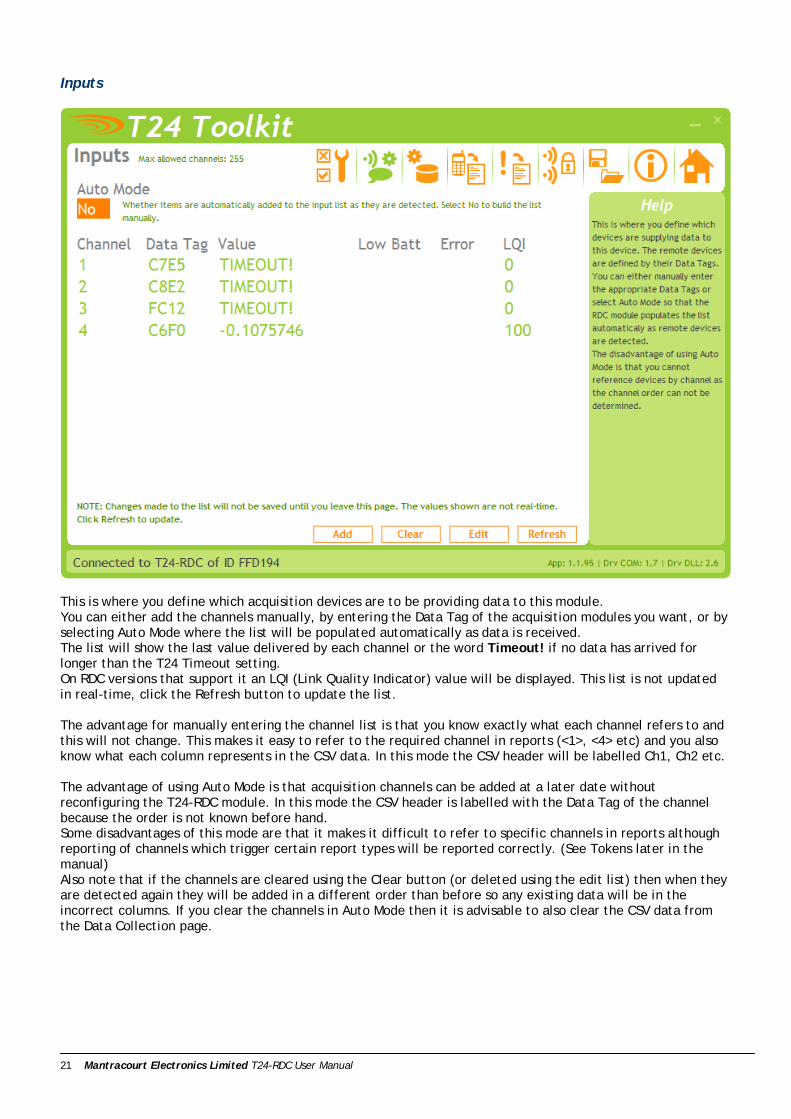
This is where you define which acquisition devices are to be providing data to this module. You can either add the channels manually, by entering the Data Tag of the acquisition modules you want, or by selecting Auto Mode where the list will be populated automatically as data is received. The list will show the last value delivered by each channel or the word Timeout! if no data has arrived for longer than the T24 Timeout setting. On RDC versions that support it an LQI (Link Quality Indicator) value will be displayed. This list is not updated in real-time, click the Refresh button to update the list. The advantage for manually entering the channel list is that you know exactly what each channel refers to and this will not change. This makes it easy to refer to the required channel in reports (<1>, <4> etc) and you also know what each column represents in the CSV data. In this mode the CSV header will be labelled Ch1, Ch2 etc. The advantage of using Auto Mode is that acquisition channels can be added at a later date without reconfiguring the T24-RDC module. In this mode the CSV header is labelled with the Data Tag of the channel because the order is not known before hand. Some disadvantages of this mode are that it makes it difficult to refer to specific channels in reports although reporting of channels which trigger certain report types will be reported correctly. (See Tokens later in the manual) Also note that if the channels are cleared using the Clear button (or deleted using the edit list) then when they are detected again they will be added in a different order than before so any existing data will be in the incorrect columns. If you clear the channels in Auto Mode then it is advisable to also clear the CSV data from the Data Collection page.
Mantracourt Electronics Limited T24-RDC User Manual 22
Items you can change: Auto Mode Whether to automatically add channels.
Add Button Clicking this will allow you to specify a new Data Tag to add.
Clear Button This clears ALL the currently configured channels.
Edit Button Changes the display to show a simple list of Data Tags. This allows quick bulk
entry of tags from an external source. You can simply paste a list of tags into the list or type them manually.
Refresh Button Refreshes the list.

Mantracourt Electronics Limited T24-RDC User Manual 23
Data Collection This page deals with the creation of the CSV data file. This can be delivered to a variety of destinations but the most useful would be either via email as an attached file or to an FTP server.
CSV File Format The format of the delivered CSV file is: Time/Date, Temperature, Ch1, Ch2, Ch3……<CR> 24/08/2010, 21.6, 123.456, 12.567, 99.762……<CR>
In the case of Auto Mode (See Inputs page) the number of fields in the CSV file may increase as new devices are detected. Also the header in Auto Mode will include the Data Tags. In non auto mode the header line states channel numbers.
Here we define the how the data is collected and when and also determine how the CSV file is formatted and where it is delivered to. The Power Mode tab lets us change the following. Items you can change: Power Mode Tab Low Power Mode Select the mode to operate in.
0 – None The device is permanently awake and can react immediately to SMS Reports and Triggered Reports. This mode would require a permanent external supply. 1 – Low Power The device sleeps in a low power mode and wakes at the Log Interval (Set in the Schedules tab) it can then react to SMS Reports and Triggered Reports. This mode is for battery powered external power. 2 – Ultra Low Power This achieves the best external battery life of all the modes but the device can

Mantracourt Electronics Limited T24-RDC User Manual 24
only react to SMS Reports and Triggered Reports when the device wakes at the CSV data transmission interval.
On Wake Wait Time This determines the minimum time (in seconds) the device remains awake at the log or transmission intervals in Low or Ultra Low Power Mode. In Ultra Low Power mode this should allow enough time for the device to capture the data supplied by the acquisition devices so may be in the order of 5 to 10 seconds. In Low Power Mode this may be increased to allow the device to process incoming SMS triggers for SMS reports. On connecting to the cellular network it may take up to 40 seconds or more for the network to send the device any stored SMS messages.
Do Sleep Wake Only used in Low Power Mode. Determines whether the device will wake acquisition modules when it wakes up itself. You can also select whether the RDC sends the modules back to sleep after a reading has been recorded. NOTE: it is advisable to also set a Sleep Delay on the acquisition modules and not rely solely on the RDC to send the modules to sleep.

Mantracourt Electronics Limited T24-RDC User Manual 25
This tab sets the intervals at which data is collected and at which the CSV data is transmitted. This has an effect on battery life as in Low and Ultra Low Power modes the Log Interval determines how often the device wakes from a very low power sleep mode. See Battery Life section Items you can change: Schedules Tab Log Interval This is the interval that the values from the acquisition modules are recorded as
a new row in the CSV data.
Every Hr Min Specify the hours and minutes between the logs.
From Hr Min The above interval is not just arbitrarily calculated from the time the device is switched on but is synchronised to real time. Here you can specify the time from midnight to synchronise the interval from. i.e. you can set an interval of 8Hr 0Min synchronised to 8Hr 0Min so the logs will take place at 8am, 2pm, 8pm and 2am.
Log Interval This is the interval that the CSV data is transmitted to the specified destinations.
Every Hr Min Specify the hours and minutes between the transmissions.
From Hr Min The above interval is not just arbitrarily calculated from the time the device is switched on but is synchronised to real time. Here you can specify the time from midnight to synchronise the interval from. i.e. you can set an interval of 8Hr 0Min synchronised to 8Hr 0Min so the logs will take place at 8am, 2pm, 8pm and 2am.
Log Window Here you can specify how much data the CSV file contains. As new data is added at the log interval any data older than the age set here will be deleted. By adjusting this time you can dramatically alter the delivered data. i.e. with a

Mantracourt Electronics Limited T24-RDC User Manual 26
CSV data delivery daily you could use a window of 1 day so that each delivery contains all logged data since the last delivery. By doubling the window yuou could deliver 2 days worth of data daily. This would protect against one delivery failing due to network unavailability for example. By setting the window to zero or less than the log interval you would delivery one line containing just the last data gathered from the acquisition devices.
Log On Alerts If this option is chosen then a log will take place every time a triggered report based on the value from an input module is triggered. (i.e. greater or less than a user defined limit). This ensures that the CSV data contains the value that caused the report to trigger. NOTE that the user of the CSV file must use the date/time stamp to determine when the data was logged and not just assume it was logged at the Log Interval!
Mantracourt Electronics Limited T24-RDC User Manual 27
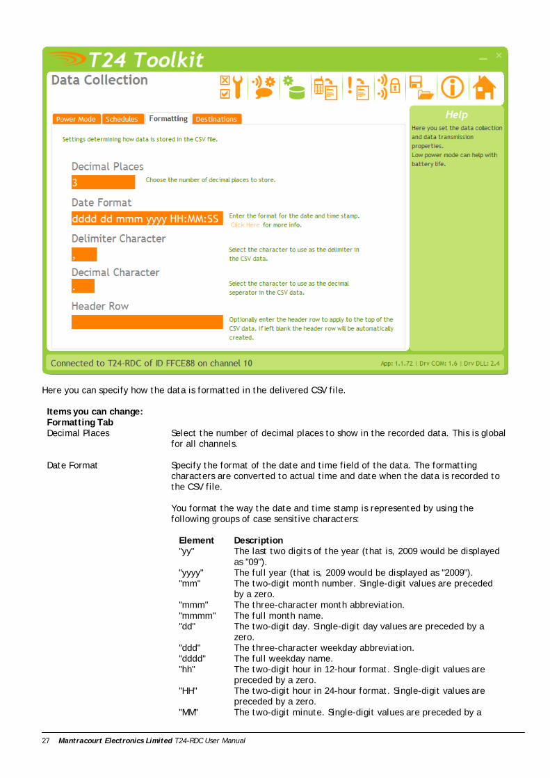
Here you can specify how the data is formatted in the delivered CSV file. Items you can change: Formatting Tab Decimal Places Select the number of decimal places to show in the recorded data. This is global
for all channels.
Date Format Specify the format of the date and time field of the data. The formatting characters are converted to actual time and date when the data is recorded to the CSV file. You format the way the date and time stamp is represented by using the following groups of case sensitive characters:
Element Description "yy" The last two digits of the year (that is, 2009 would be displayed
as "09"). "yyyy" The full year (that is, 2009 would be displayed as "2009"). "mm" The two-digit month number. Single-digit values are preceded
by a zero. "mmm" The three-character month abbreviation. "mmmm" The full month name. "dd" The two-digit day. Single-digit day values are preceded by a
zero. "ddd" The three-character weekday abbreviation. "dddd" The full weekday name. "hh" The two-digit hour in 12-hour format. Single-digit values are
preceded by a zero. "HH" The two-digit hour in 24-hour format. Single-digit values are
preceded by a zero. "MM" The two-digit minute. Single-digit values are preceded by a

Mantracourt Electronics Limited T24-RDC User Manual 28
zero. "SS" The two-digit second. Single-digit values are preceded by a
zero. "TT" The two-letter AM/PM abbreviation (that is, AM is displayed as
"AM"). "ee" The full time and date encoded numerically in the MS Excel
format. "EE" Epoch format in milliseconds elapsed since 01/01/1970.
Any other characters will form part of the formatted output. i.e. ‘mmmm dd yyyy at HH:MM:SS’ would decode to ‘January 15 2009 at 12:23:05’
Delimiter Character Specify the character used between the values. Usually the UK setting would be a comma but some countries use a semi-colon.
Decimal Character Specify the decimal separator. Usually in the UK this would be a decimal point but some countries would use a comma.
Header Row You can override the automatic header row at the top of the CSV file by entering a custom one here. i.e. Date,IntTemp,Strut1,Strut2,ExtTemp
Mantracourt Electronics Limited T24-RDC User Manual 29
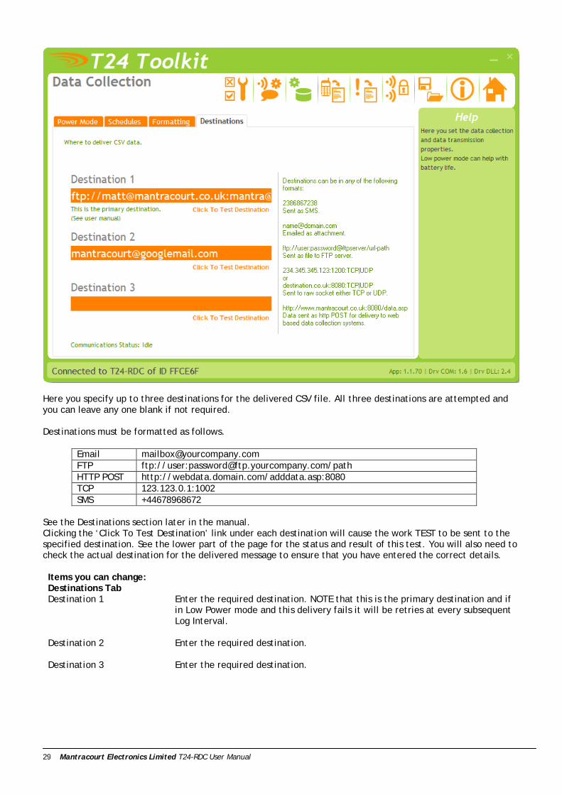
Here you specify up to three destinations for the delivered CSV file. All three destinations are attempted and you can leave any one blank if not required. Destinations must be formatted as follows.
Email [email protected] FTP ftp://user:[email protected]/path HTTP POST http://webdata.domain.com/adddata.asp:8080 TCP 123.123.0.1:1002 SMS +44678968672
See the Destinations section later in the manual. Clicking the ‘Click To Test Destination’ link under each destination will cause the work TEST to be sent to the specified destination. See the lower part of the page for the status and result of this test. You will also need to check the actual destination for the delivered message to ensure that you have entered the correct details. Items you can change: Destinations Tab Destination 1 Enter the required destination. NOTE that this is the primary destination and if
in Low Power mode and this delivery fails it will be retries at every subsequent Log Interval.
Destination 2 Enter the required destination.
Destination 3 Enter the required destination.

Mantracourt Electronics Limited T24-RDC User Manual 30
SMS Reports These reports are triggered by sending the device an SMS message. On receipt of the correct password the device will reply with the user defined report text to the sending phone.
The ten reports can be accessed by clicking the appropriate numbered tab at the top of the page. NOTE that the changes are not saved until you click to another page. Items you can change: Password Enter the case insensitive password that must be on the first line of the SMS
message to trigger this report response.
Message Compose the response message here. This message can contain tokens that are decoded at the time of message generation and can contain real time values such as battery voltage or channel values. See Tokens section later in manual. NOTE: if you specify just a question mark (?) as the message content then the contents of the triggering SMS message (after the password line) are used to create the response message. Therefore you can create the desired message including tokens remotely to receive any custom information required.

Mantracourt Electronics Limited T24-RDC User Manual 31
Remote Configuration Password
Here you can set a password, that if received as the first line of an SMS message, will take the rest of the SMS message as a configuration script. This allows you to change some parameters remotely via SMS. Just blank the password to disable this feature. To use this feature you would send a message the device with the password (case insensitive) on the first line followed by a set of parameter=value instructions. Each line is evaluated and the specified value is applied to the parameter. If an error occurs processing of further instruction lines is halted. You will get a response SMS message showing which instructions were set OK and where failures (if any) occurred. Example SMS ConfigPassword sn=My New Name SILENT=0 cd1=+44897987978
Example Response sn=My New Name OK SILENT=0 OK cd1=+44897987978 OK
If there is a problem setting the value you may see one of the following errors: NAK The data was rejected by the T24-RDC as Not Acknowledged Invalid Data The data itself was rejected by the device Unknown The parameter that was stated was unknown/unrecognised Error An unforeseen error has occurred
NOTE: Some phones make adding a carriage return difficult. You can use the pipe character as an alternative to a line break (The pipe character is the vertical bar ‘|’). So for the above example you could send: ConfigPassword|sn=My New Name|SILENT=0|cd1=+44897987978
See the next section for a list of valid property names for use in the SMS messages. NOTE: Depending on the low power mode selected you may not see an SMS response until the next log interval or in the case of ultra low power mode until the next transmission of the CSV data.
Mantracourt Electronics Limited T24-RDC User Manual 32
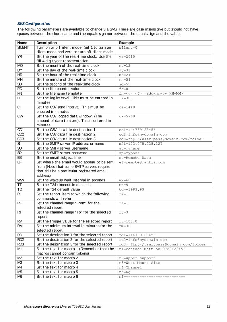
SMS Configuration The following parameters are available to change via SMS. There are case insensitive but should not have spaces between the short name and the equals sign nor between the equals sign and the value. Name Description Example SILENT Turn on or off silent mode. Set 1 to turn on
silent mode and zero to turn off silent mode silent=0
YR Set the year of the real-time clock. Use the fill 4 digit year representation
yr=2010
MO Set the month of the real-time clock mo=12 DY Set the day of the real-time clock dy=31 HR Set the hour of the real-time clock hr=24 MN Set the minute of the real-time clock mn=59 SD Set the second of the real-time clock sd=59 FC Set the file counter value fc=0 FN Set the filename template fn=<y> <f> <@dd-mm-yy HH-MM> LI Set the log interval. This must be entered in
minutes li=300
CI Set the CSV send interval. This must be entered in minutes
ci=1440
CW Set the CSV logged data window. (The amount of data to store). This is entered in minutes
cw=5760
CD1 Set the CSV data file destination 1 cd1=+44789123456 CD2 Set the CSV data file destination 2 [email protected] CD3 Set the CSV data file destination 3 cd3=ftp://user:[email protected]/folder SI Set the SMTP server IP address or name sSi=123.075.035.127 SU Set the SMTP server username su=myname SP Set the SMTP server password sp=mypass ES Set the email subject line es=Remote Data EF Set where the email would appear to be sent
from (Note that some SMTP servers require that this be a particular registered email address)
WW Set the wakeup wait interval in seconds ww=60 TT Set the T24 timeout in deconds tt=5 TD Set the T24 default value td=-1999.99 RI Set the report item to which the following
commands will refer ri=1
RF Set the channel range ‘From’ for the selected report
rf=1
RT Set the channel range ‘To’ for the selected report
rt=3
RV Set the trigger value for the selected report rv=100.0 RM Set the minimum interval in minutes for the
selected report rm=30
RD1 Set the destination 1 for the selected report rd1=+44789123456 RD2 Set the destination 2 for the selected report [email protected] RD3 Set the destination 3 for the selected report rd3= ftp://user:[email protected]/folder M1 Set the text for macro 1 (Remember that the
macros cannot contain tokens) m1=contact Matt on 0789123456
M2 Set the text for macro 2 m2=upper support M3 Set the text for macro 3 m3=West Mount Site M4 Set the text for macro 4 m4=Channel M5 Set the text for macro 5 m5=Kg M6 Set the text for macro 6 m6=--------------------------

Mantracourt Electronics Limited T24-RDC User Manual 33
Triggered Reports
There are 20 reports that can be pre-defined and triggered by local events or at set intervals. These can deliver alert/alarm type information or just deliver data to data collections systems etc Click on one of the numbered tabs to select a particular report to edit. NOTE that the changes made while on this page are not saved until you select a different page (not just a different numbered tab). Items you can change: Trigger Tab Report Trigger Here you can select the type of trigger for sending the report. Certain triggers
may cause other fields on this page to be disabled. 0-Disabled This report is disabled 1-Greater Than Limit Check the specified channel range against the
specified value and trigger the report if the channel value exceeds this value
2-Less Than Limit Check the specified channel range against the specified value and trigger the report if the channel value is less than this value
3-Remote Integrity Error Check the specified channels and trigger the report if any report an integrity error (A problem with their input)
4-Remote Low Battery Check the specified channels and trigger the report if any report a low battery
Mantracourt Electronics Limited T24-RDC User Manual 34
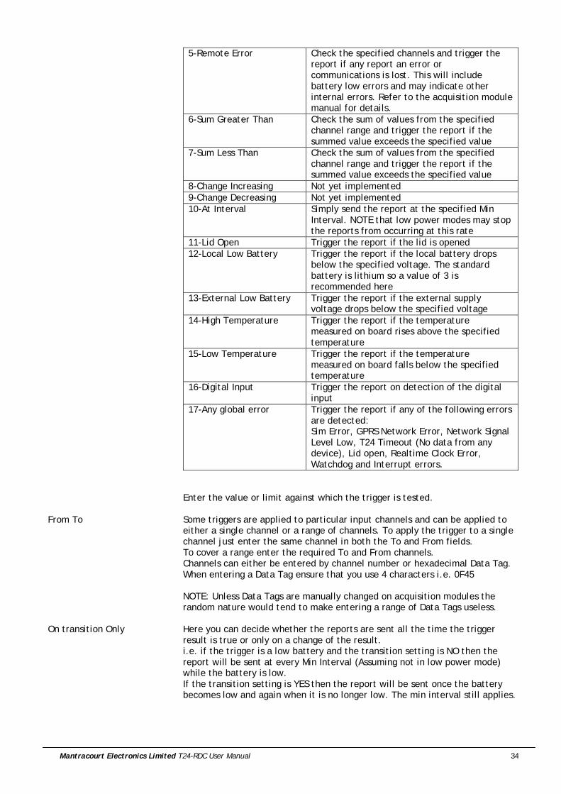
5-Remote Error Check the specified channels and trigger the report if any report an error or communications is lost. This will include battery low errors and may indicate other internal errors. Refer to the acquisition module manual for details.
6-Sum Greater Than Check the sum of values from the specified channel range and trigger the report if the summed value exceeds the specified value
7-Sum Less Than Check the sum of values from the specified channel range and trigger the report if the summed value exceeds the specified value
8-Change Increasing Not yet implemented 9-Change Decreasing Not yet implemented 10-At Interval Simply send the report at the specified Min
Interval. NOTE that low power modes may stop the reports from occurring at this rate
11-Lid Open Trigger the report if the lid is opened 12-Local Low Battery Trigger the report if the local battery drops
below the specified voltage. The standard battery is lithium so a value of 3 is recommended here
13-External Low Battery Trigger the report if the external supply voltage drops below the specified voltage
14-High Temperature Trigger the report if the temperature measured on board rises above the specified temperature
15-Low Temperature Trigger the report if the temperature measured on board falls below the specified temperature
16-Digital Input Trigger the report on detection of the digital input
17-Any global error Trigger the report if any of the following errors are detected: Sim Error, GPRS Network Error, Network Signal Level Low, T24 Timeout (No data from any device), Lid open, Realtime Clock Error, Watchdog and Interrupt errors.
Enter the value or limit against which the trigger is tested.
From To Some triggers are applied to particular input channels and can be applied to either a single channel or a range of channels. To apply the trigger to a single channel just enter the same channel in both the To and From fields. To cover a range enter the required To and From channels. Channels can either be entered by channel number or hexadecimal Data Tag. When entering a Data Tag ensure that you use 4 characters i.e. 0F45 NOTE: Unless Data Tags are manually changed on acquisition modules the random nature would tend to make entering a range of Data Tags useless.
On transition Only Here you can decide whether the reports are sent all the time the trigger result is true or only on a change of the result. i.e. if the trigger is a low battery and the transition setting is NO then the report will be sent at every Min Interval (Assuming not in low power mode) while the battery is low. If the transition setting is YES then the report will be sent once the battery becomes low and again when it is no longer low. The min interval still applies.
Mantracourt Electronics Limited T24-RDC User Manual 35
Min Interval This is the minimum interval in minutes between delivery of the report. The minimum number you can enter is 1. Unlike the data log and CSV send intervals these intervals are not tied to absolute time but are timed from the last sending of the report. Also bear in mind that in Low Power or Ultra Low Power modes reports could not be delivered more regularly than the Log Interval or the CSV Delivery Interval respectively.

Mantracourt Electronics Limited T24-RDC User Manual 36
On the previous Trigger Tab you select whether the report is triggered transitionally or not. If triggered transitionally you can specify not only the message to send when the trigger test is true but also a message to send when the trigger test returns to false again. In the above example you can see that the No Trigger message is disabled because this is not a transitional triggered report. Items you can change: Trigger Tab Message On Trigger Enter the report to send when the trigger test returns true. This report can
contain tokens which get decoded to useful information when the report is transmitted. See Tokens later in the manual. For example the message for a report that is triggered on low internal battery may read: WARNING: Internal battery low at <v> Volts.
Message On No Trigger On transitionally triggered reports this message is used when the trigger
criteria is no longer met. For example a report triggered on low internal battery would send this message when the battery voltage is OK. i.e. Internal battery voltage is OK at <v> Volts.
Mantracourt Electronics Limited T24-RDC User Manual 37
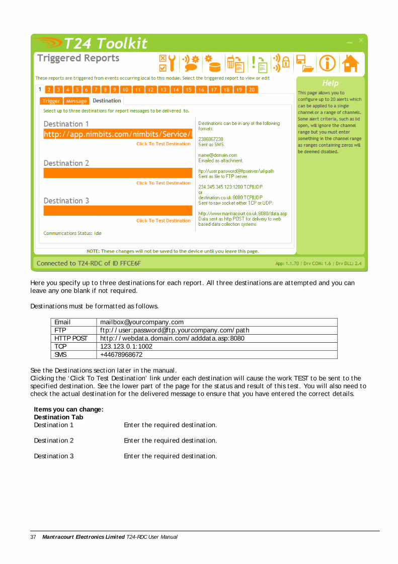
Here you specify up to three destinations for each report. All three destinations are attempted and you can leave any one blank if not required. Destinations must be formatted as follows.
Email [email protected] FTP ftp://user:[email protected]/path HTTP POST http://webdata.domain.com/adddata.asp:8080 TCP 123.123.0.1:1002 SMS +44678968672
See the Destinations section later in the manual. Clicking the ‘Click To Test Destination’ link under each destination will cause the work TEST to be sent to the specified destination. See the lower part of the page for the status and result of this test. You will also need to check the actual destination for the delivered message to ensure that you have entered the correct details. Items you can change: Destination Tab Destination 1 Enter the required destination.
Destination 2 Enter the required destination.
Destination 3 Enter the required destination.
Mantracourt Electronics Limited T24-RDC User Manual 38
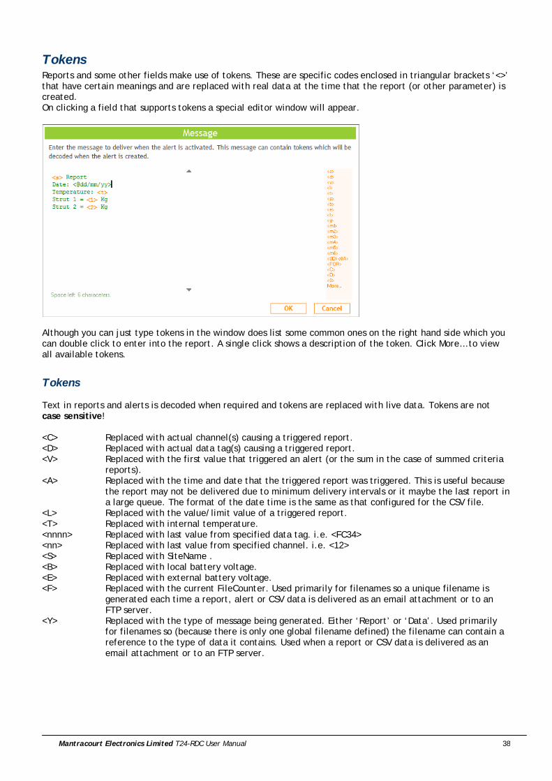
Tokens Reports and some other fields make use of tokens. These are specific codes enclosed in triangular brackets ‘<>’ that have certain meanings and are replaced with real data at the time that the report (or other parameter) is created. On clicking a field that supports tokens a special editor window will appear.
Although you can just type tokens in the window does list some common ones on the right hand side which you can double click to enter into the report. A single click shows a description of the token. Click More… to view all available tokens.
Tokens Text in reports and alerts is decoded when required and tokens are replaced with live data. Tokens are not case sensitive! <C> Replaced with actual channel(s) causing a triggered report. <D> Replaced with actual data tag(s) causing a triggered report. <V> Replaced with the first value that triggered an alert (or the sum in the case of summed criteria
reports). <A> Replaced with the time and date that the triggered report was triggered. This is useful because
the report may not be delivered due to minimum delivery intervals or it maybe the last report in a large queue. The format of the date time is the same as that configured for the CSV file.
<L> Replaced with the value/limit value of a triggered report. <T> Replaced with internal temperature. <nnnn> Replaced with last value from specified data tag. i.e. <FC34> <nn> Replaced with last value from specified channel. i.e. <12> <S> Replaced with SiteName . <B> Replaced with local battery voltage. <E> Replaced with external battery voltage. <F> Replaced with the current FileCounter. Used primarily for filenames so a unique filename is
generated each time a report, alert or CSV data is delivered as an email attachment or to an FTP server.
<Y> Replaced with the type of message being generated. Either ‘Report’ or ‘Data’. Used primarily for filenames so (because there is only one global filename defined) the filename can contain a reference to the type of data it contains. Used when a report or CSV data is delivered as an email attachment or to an FTP server.
Mantracourt Electronics Limited T24-RDC User Manual 39
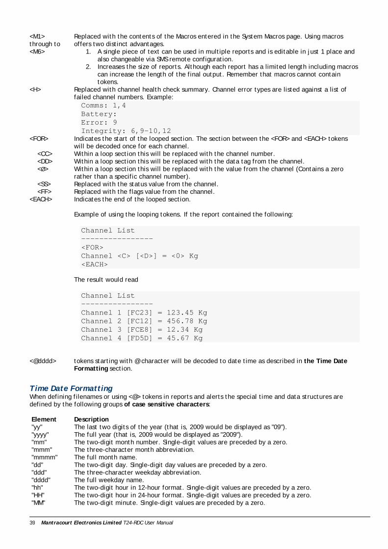
<M1> through to <M6>
Replaced with the contents of the Macros entered in the System Macros page. Using macros offers two distinct advantages.
1. A single piece of text can be used in multiple reports and is editable in just 1 place and also changeable via SMS remote configuration.
2. Increases the size of reports. Although each report has a limited length including macros can increase the length of the final output. Remember that macros cannot contain tokens.
<H> Replaced with channel health check summary. Channel error types are listed against a list of failed channel numbers. Example: Comms: 1,4 Battery: Error: 9 Integrity: 6,9-10,12
<FOR> Indicates the start of the looped section. The section between the <FOR> and <EACH> tokens will be decoded once for each channel.
<CC> Within a loop section this will be replaced with the channel number. <DD> Within a loop section this will be replaced with the data tag from the channel. <Ø> Within a loop section this will be replaced with the value from the channel (Contains a zero
rather than a specific channel number). <SS> Replaced with the status value from the channel. <FF> Replaced with the flags value from the channel. <EACH> Indicates the end of the looped section.
Example of using the looping tokens. If the report contained the following: Channel List ---------------- <FOR> Channel <C> [<D>] = <0> Kg <EACH>
The result would read Channel List ---------------- Channel 1 [FC23] = 123.45 Kg Channel 2 [FC12] = 456.78 Kg Channel 3 [FCE8] = 12.34 Kg Channel 4 [FD5D] = 45.67 Kg
<@dddd> tokens starting with @ character will be decoded to date time as described in the Time Date Formatting section.
Time Date Formatting When defining filenames or using <@> tokens in reports and alerts the special time and data structures are defined by the following groups of case sensitive characters: Element Description "yy" The last two digits of the year (that is, 2009 would be displayed as "09"). "yyyy" The full year (that is, 2009 would be displayed as "2009"). "mm" The two-digit month number. Single-digit values are preceded by a zero. "mmm" The three-character month abbreviation. "mmmm" The full month name. "dd" The two-digit day. Single-digit day values are preceded by a zero. "ddd" The three-character weekday abbreviation. "dddd" The full weekday name. "hh" The two-digit hour in 12-hour format. Single-digit values are preceded by a zero. "HH" The two-digit hour in 24-hour format. Single-digit values are preceded by a zero. "MM" The two-digit minute. Single-digit values are preceded by a zero.

Mantracourt Electronics Limited T24-RDC User Manual 40
"SS" The two-digit second. Single-digit values are preceded by a zero. "TT" The two-letter AM/PM abbreviation (that is, AM is displayed as "AM"). "ee" The full time and date encoded numerically in the MS Excel format. "EE" Epoch format in milliseconds elapsed since 01/01/1970.
Any other characters will form part of the formatted output. i.e. ‘<@mmmm dd yyyy at HH:MM:SS>’ would decode to ‘January 15 2009 at 12:23:05’
Mantracourt Electronics Limited T24-RDC User Manual 41
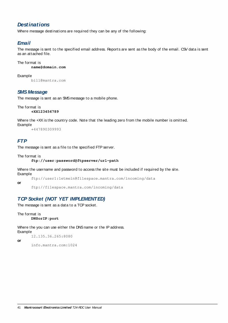
Destinations Where message destinations are required they can be any of the following:
Email The message is sent to the specified email address. Reports are sent as the body of the email. CSV data is sent as an attached file. The format is
Example [email protected]
SMS Message The message is sent as an SMS message to a mobile phone. The format is
+XX123456789
Where the +XX is the country code. Note that the leading zero from the mobile number is omitted. Example
+447890309993
FTP The message is sent as a file to the specified FTP server. The format is
ftp://user:password@ftpserver/url-path Where the username and password to access the site must be included if required by the site. Example
ftp://user1:[email protected]/incoming/data or
ftp://filespace.mantra.com/incoming/data
TCP Socket (NOT YET IMPLEMENTED) The message is sent as a data to a TCP socket. The format is
DNSorIP:port Where the you can use either the DNS name or the IP address. Example
12.135.36.265:8080 or
info.mantra.com:1024

Mantracourt Electronics Limited T24-RDC User Manual 42
HTTP Post The message is sent as the data content of an HTTP POST. This is useful for getting data into a web service or site. The format is
http://domain:port/path Where you can use either the DNS name or the IP address. Example
http://mantra.com:80/cgi-bin or
http://mantra.com/adddata.asp As this posts data the same way as does submitting data from forms in web pages etc it is very easy to handle data delivered by this method into web sites and data collection systems. Design your message to just contain the parameters and values. i.e. V1=<1>&V2=<2>&DATESTAMP=<@ddmmyyyy>
The device wraps up the other required header text to deliver the POST to the destination. As an example if the destination was http://host.com/Service/batch
and your report message was V1=<1>&V2=<2>&DATESTAMP=<@ddmmyyyy>
The actual delivered data would be POST http://host.com/Service/batch HTTP/1.0 Host: host.com Content-Type: application/x-www-form-urlencoded Content-Length: 40 V1=123.456&V2=456.789&DATESTAMP=31122010
Now the receiving destination just needs to deal with the parameters. For example if we delivered the above data to an ASP page URL then we can extract the data as follows X = Request.Form("V1") Y = Request.Form("V2") Z = Request.Form("DATESTAMP")
Custom Headers You can add custom lines to the header (See System page POST in T24 Toolkit) which will allow authorization details and other security information to be added to the HTTP header if the site you are posting data to requires it. POST http://host.com/Service/batch HTTP/1.0 Host: host.com Content-Type: application/x-www-form-urlencoded CUSTOM HEADER ITEMS APPEAR HERE Content-Length: 40 V1=123.456&V2=456.789&DATESTAMP=31122010
Mantracourt Electronics Limited T24-RDC User Manual 43
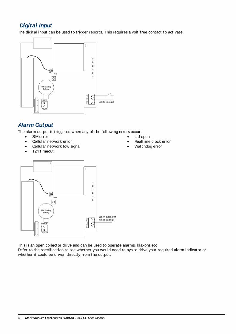
Digital Input The digital input can be used to trigger reports. This requires a volt free contact to activate.
RTC BackupBattery
Volt free contact
Alarm Output The alarm output is triggered when any of the following errors occur:
• SIM error • Cellular network error • Cellular network low signal • T24 timeout
• Lid open • Realtime clock error • Watchdog error
RTC BackupBattery
Open collectoralarm output
This is an open collector drive and can be used to operate alarms, klaxons etc Refer to the specification to see whether you would need relays to drive your required alarm indicator or whether it could be driven directly from the output.

Mantracourt Electronics Limited T24-RDC User Manual 44
Installation
Overview Radio performance at microwave wavelengths is very dependent upon the operating environment; any structure within the operating region of the radios will give rise to three effects: Obscuration. Obscuration will result in reduced range and occurs when an obstruction masks the line-of-sight between radios. Aberrations to the horizontal and vertical space patterns. Distortion of these patterns may occur if structures or objects are placed in the near or intermediate field of the antenna. The effect will be to distort the coverage patterns, adversely affecting range and link quality. Reflection. Any object placed in line-of-sight of the transmit antenna will result in signals arriving at the receiver by an indirect path. Degradation of performance due to reflection (multipath effects) appears as reduced range or poor link quality. Any of the above will cause poor RSSI figures, an increase in the packet loss rate and in extreme cases complete loss of signal. Fortunately, if consideration is given to these effects at the integration stage then a good quality link will be obtained. Guidelines for product design: When selecting materials for product enclosures, preference should be given to fibreglass, light coloured ABS or Polypropylene; at the wavelength of 2.4GHz radio other materials will adversely affect the signal by attenuation, refraction or change in polarisation. If the application demands that the radio is fitted inside a metal enclosure then ensure that the specified clearances are maintained around the antenna and design in a fibreglass RF window at least as large as the clearance dimensions but ideally as large as possible. RAD24i radios fitted inside a product should be oriented so that the chip antenna will be vertical when the product is in its normal operating position. Guidelines for installation: When planning installations ensure that line-of –sight between nodes is maintained and that objects or structures are kept at least one metre away from antennae wherever possible. To avoid poor link quality between a RAD24i radio and a handheld device ensure that the RAD24i is mounted so that the chip antenna is vertical. Improvement may also be obtained by altering the height above ground of the RAD24i; a small increase or reduction in antenna elevation will often improve reception. Range underwater is only a decimetre or so depending on packet rate. Best performance underwater is obtained by using low packet rates and immersing water-proofed antennae rather than water-tight enclosures containing the antennae.

Mantracourt Electronics Limited T24-RDC User Manual 45
Battery Life Although the T24-RDC has an internal battery it is designed to be supplied from an external battery or power source. The low power modes can make a big difference to battery life. The following scenarios give a guide to battery life and the charts show how long the batteries of a given Ah capacity would last. In real use the full capacity of batteries may not be usable as the T24-RDC can only run down to 4.5V. Also operating temperature and self discharge of the batteries will also play a part.
Scenario 1 Data is logged at an interval of 1 hour. The sample time on waking (if relevant) is 2 minutes. The interval for transmitting the CSV file to a single email destination is every 24 hours. The average current drawn: Low Power Mode None Low Ultra Milliamps 53 6.2 2.4
Scenario 1 Log:1hr Send:24hr Low Power Modes
0.0
50.0
100.0
150.0
200.0
250.0
300.0
0 20 40 60 80 100 120
Battery Capacity (Amp Hours)
Bat
tery
Life
(Wee
ks)
None Low Ultra
Mantracourt Electronics Limited T24-RDC User Manual 46
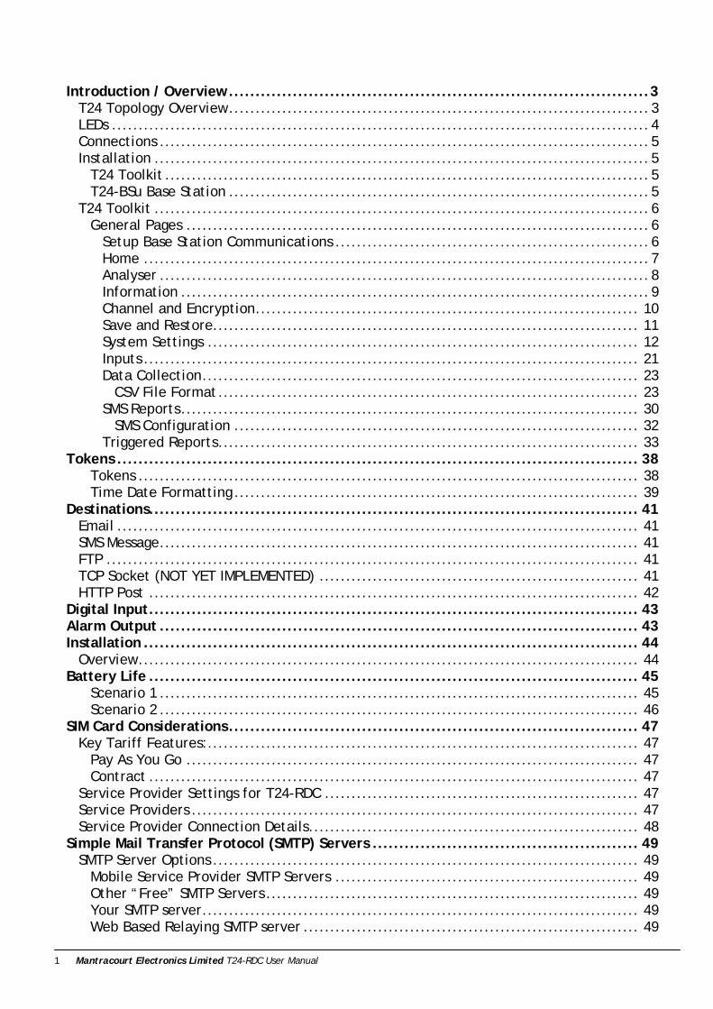
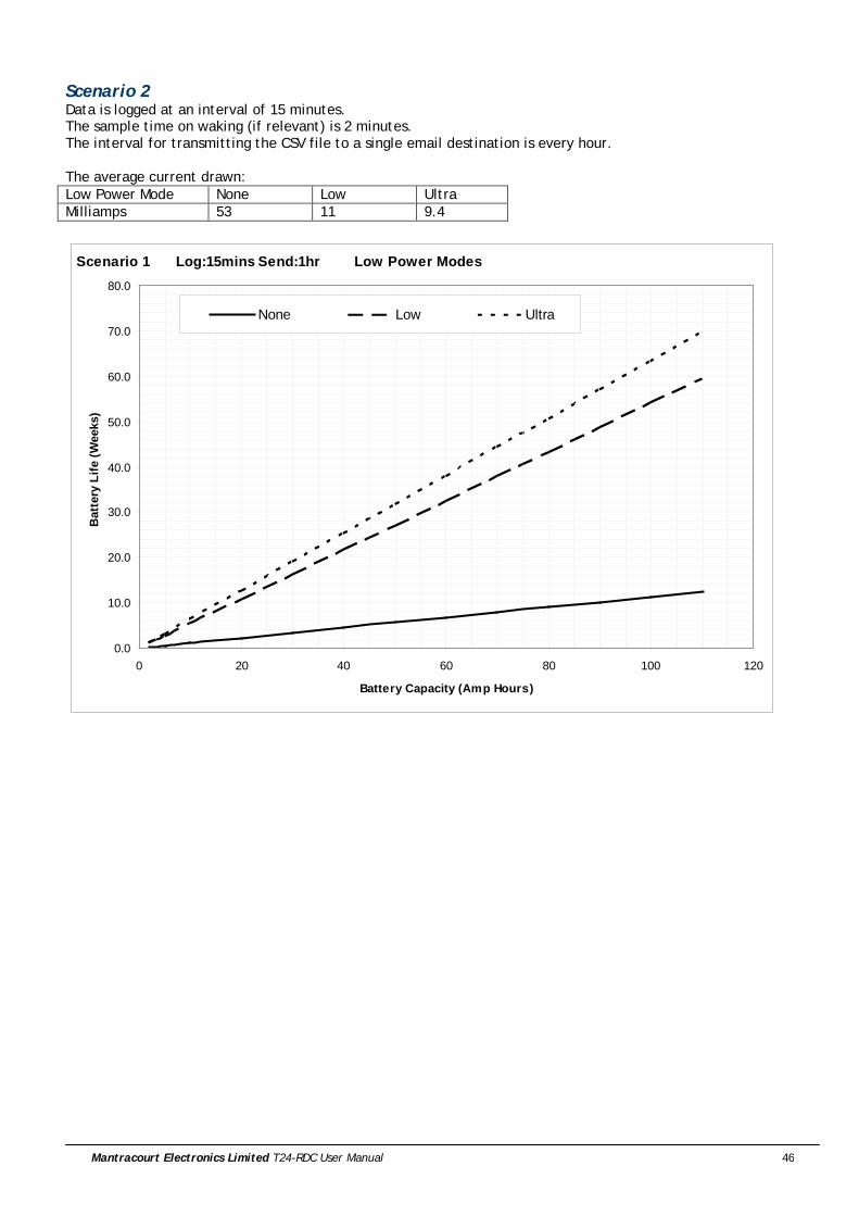
Scenario 2 Data is logged at an interval of 15 minutes. The sample time on waking (if relevant) is 2 minutes. The interval for transmitting the CSV file to a single email destination is every hour. The average current drawn: Low Power Mode None Low Ultra Milliamps 53 11 9.4
Scenario 1 Log:15mins Send:1hr Low Power Modes
0.0
10.0
20.0
30.0
40.0
50.0
60.0
70.0
80.0
0 20 40 60 80 100 120
Battery Capacity (Amp Hours)
Bat
tery
Life
(Wee
ks)
None Low Ultra

Mantracourt Electronics Limited T24-RDC User Manual 47
SIM Card Considerations Key Tariff Features:
• Internet Usage Costs o PAYG 5p / day o Contract Included in monthly allowance o Fair Usage Allowance (5MB / day)
• SMS Allowance o Depending on Reports
• Call Credit o The T24-RDC does not require any air time minutes
Pay As You Go • Top Up as you require must register for online top-up before sending out module • Alternatively Direct Debit Top up when credit goes below £5 • Higher internet usage charges • Lower Internet Usage Allowance / Fair Usage • SIM card must be registered or network access is limited
Contract • Constant Cost when SIM card not in use with T24-RDC • Higher quality of service
Service Provider Settings for T24-RDC Access Point Name (APN) Effectively the service provider website portal to give access to the internet User Name & Password
These are provided to give you access to the internet, the same provider may have different usernames and passwords for PAYG vs Contract customers to distinguish users.
Service Providers All service providers have different coverage, the below website allows you to check service providers coverage using you postcode as the reference location. http://www.gadgetstylist.com/blog/mobile-phone-coverage-check-your-mobile-coverage/ The same network may get access to different types of internet connection, GPRS, Edge, 3G, HSDPA (High speed Downlink Packet Access) depending on location. The key difference between all these connection types is speed, hence time that the T24-RDC has to be awake. All of these connection types are viable and the T24-RDC will negotiate the best possible service for its current location.
Mantracourt Electronics Limited T24-RDC User Manual 48
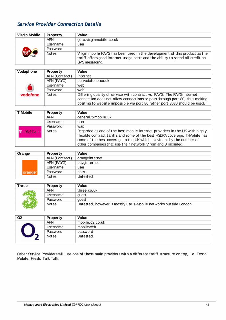
Service Provider Connection Details Virgin Mobile Property Value
APN goto.virginmobile.co.uk Username user Password Notes Virgin mobile PAYG has been used in the development of this product as the
tariff offers good internet usage costs and the ability to spend all credit on SMS messaging.
Vodaphone Property Value
APN (Contract) internet APN (PAYG) pp.vodafone.co.uk Username web Password web Notes Differing quality of service with contract vs. PAYG. The PAYG internet
connection does not allow connections to pass through port 80, thus making positing to website impossible via port 80 rather port 8080 should be used.
T Mobile Property Value
APN general.t-mobile.uk Username user Password wap Notes Regarded as one of the best mobile internet providers in the UK with highly
flexible contract tariffs and some of the best HSDPA coverage. T-Mobile has some of the best coverage in the UK which is evident by the number of other companies that use their network Virgin and 3 included.
Orange Property Value
APN (Contract) orangeinternet APN (PAYG) payginternet Username user Password pass Notes Untested
Three Property Value
APN three.co.uk Username guest Password guest Notes Untested, however 3 mostly use T-Mobile networks outside London.
O2 Property Value
APN mobile.o2.co.uk Username mobileweb Password password Notes Untested.
Other Service Providers will use one of these main providers with a different tariff structure on top, i.e. Tesco Mobile, Fresh, Talk Talk.

Mantracourt Electronics Limited T24-RDC User Manual 49
Simple Mail Transfer Protocol (SMTP) Servers The T24-RDC requires the name or the IP address of an SMTP server as part of its configuration. The SMTP server delivers messages on behalf of the user; the T24-RDC can use the services of an e-mail provider that is not necessarily the same as the connection provider (ISP). This means the location of a client within a network or outside of a network, is not a limiting factor for e-mail submission or delivery, i.e. the same SMTP server can be used regardless of the ISP being used. Some ISP’s intercept port 25, so that it is not possible for their users to send mail via a relaying SMTP server outside the ISP's network using port 25; they are restricted to using the ISP's SMTP server. Some independent SMTP servers support an additional port other than 25 to allow users with authenticated access to connect to them even if port 25 is blocked. The practical purpose of this is that a mobile user connecting to different ISPs otherwise has to change SMTP server settings on the mail client for each ISP; using a relaying SMTP server allows the SMTP client settings to be used unchanged worldwide. The SMTP service must support AUTH LOGIN authentication or allow unauthenticated access.
SMTP Server Options
Mobile Service Provider SMTP Servers Most Mobile operators have an SMTP server for their customers to use, in many cases users create accounts on the mobile provider website that they can then access through their phone. The services are free however they are limited in the respect that only one email address is available to send mail from and it will generally end with the company’s name, i.e. [email protected]
Other “Free” SMTP Servers There are many free SMTP service providers however nothing comes for free, each will have a catch. Either similarly to mobile provider SMTP servers you will only be able use a single email address with the companies name in it, or there will be very low usage allowance on the account.
Your SMTP server Most companies now have their own SMTP server as part of their IT infrastructure this can be used as a relaying SMTP server, however this does require the SMTP server to be exposed onto the internet. Obviously there is no running cost and no limit to the email addresses mail can be sent from, however it can pose a security issue for system administrators as it could be possible to configure the T24-RDC to overrun an SMTP server which could then in turn over run your companies SMTP server. In Addition some maintenance would be required if the senders email addresses were changed.
Web Based Relaying SMTP server Mantracourt has gone down the path of outsourcing our SMTP server forwarding to a web based SMTP server. This allows us to send emails from any device from a PC to T24-RDC using any validated sender email address. Sending Email addresses are validated by the relaying SMTP server via an authentication email to the email account. The cost of this service is variable depending on the amount of data being sent; typically a service relaying 1000 emails with up to a total 1.0GB of attachments from up to 55 different email addresses per month will cost £100 per annum. Using a relaying service removes any risk of using your company server as well as allowing you to choose a multitude of senders email addresses. Also by using a relay service it does not matter which service provider you are using. You can also check you service usage and adjust your price package online allowing easy management of the T24-RDC overheads.
SMTP Server Providers www.authsmtp.com (Mantracourt’s Provider) www.simplymailsoloutions.com
www.smtp.com www.SMTP-Mail-Server.com

Mantracourt Electronics Limited T24-RDC User Manual 50
Specifications
General Radio Min Typical Max Units License License Exempt Modulation method MS (QPSK) Radio type Transceiver (2 way) Data rate 250 K bits/sec Radio Frequency 2.4000 2.4835 GHz Power 1 mw Range 200 (650) Metres (feet)* Channels (DSSS) 16 * Maximum range achieved in open field site at a height of 3 metres above ground.
T24-RDC Parameter Minimum Typical Maximum Units Notes External Supply voltage Range
9 12 32 V DC
Average Operational Current
- TBD 500 mA
Operating Temperature Range
-20 - 70 Deg C
Storage Temperature Range
-20 - 70 Deg C
Reverse polarity Protection
- -32 V DC Maximum Supply level
Grey ABS Enclosure IP65 120 x 122 x 55mm
Physical Dimensions

Mantracourt Electronics Limited T24-RDC User Manual 51
Approvals
CE
Complies with EMC directive. 2004/108/EC The Radio Equipment and Telecommunications Terminal Equipment (R&TTE) Directive, 1999/5/EC, European Community, Switzerland, Norway, Iceland, and Liechtenstein English: This equipment is in compliance with the essential requirements and other relevant provisions of
Directive 1999/5/EC. Deutsch: Dieses Gerät entspricht den grundlegenden Anforderungen und den weiteren entsprecheneden
Vorgaben der Richtlinie 1999/5/EU. Dansk: Dette udstyr er i overensstemmelse med de væsentlige krav og andre relevante bestemmelser i
Directiv 1999/5/EF. Español: Este equipo cumple con los requisitos esenciales asi como con otras disposiciones de la Directive
1999/5/EC. Français: Cet appareil est conforme aux exigencies essentialles et aux autres dispositions pertinantes de la
Directive 1999/5/EC. Íslenska: Þessi búnaður samrýmist lögboðnum kröfum og öðrum ákvæðum tilskipunar 1999/5/ESB. Italiano: Questo apparato é conforme ai requisiti essenziali ed agli altri principi sanciti dalla Direttiva
1999/5/EC. Nederlands: Deze apparatuur voldoet aan de belangrijkste eisen en andere voorzieningen van richtlijn
1999/5/EC. Norsk: Dette utstyret er i samsvar med de grunnleggende krav og andre relevante bestemmelser i EU-
directiv 1999/5/EC. Português: Este equipamento satisfaz os requisitos essenciais e outras provisões da Directiva 1999/5/EC. Suomalainen: Tämä laite täyttää direktiivin 1999/5/EY oleelliset vaatimukset ja on siinä asetettujen muidenkin
ehtojen mukainen. Svenska: Denna utrustning är i överensstämmelse med de väsentliga kraven och andra relevanta
bestämmelser i Direktiv 1999/5/EC. This equipment is in compliance with the essential requirements and other relevant provisions of Directive 1999/5/EC.
FCC
Family: RAD24 Models: i and e for internal and external antenna variants. For antenna T24-ANTA and T24-ANTB FCC ID:VHARAD24 This device complies with Part 15c of the FCC Rules. Operation is subject to the following two conditions: (1) this device may not cause harmful interference, and (2) this device must accept any interference received, including interference that may cause undesired operation. CAUTION: If the device is changed or modified without permission from Mantracourt Electronics Ltd, the user may void his or her authority to operate the equipment.
Mantracourt Electronics Limited T24-RDC User Manual 52
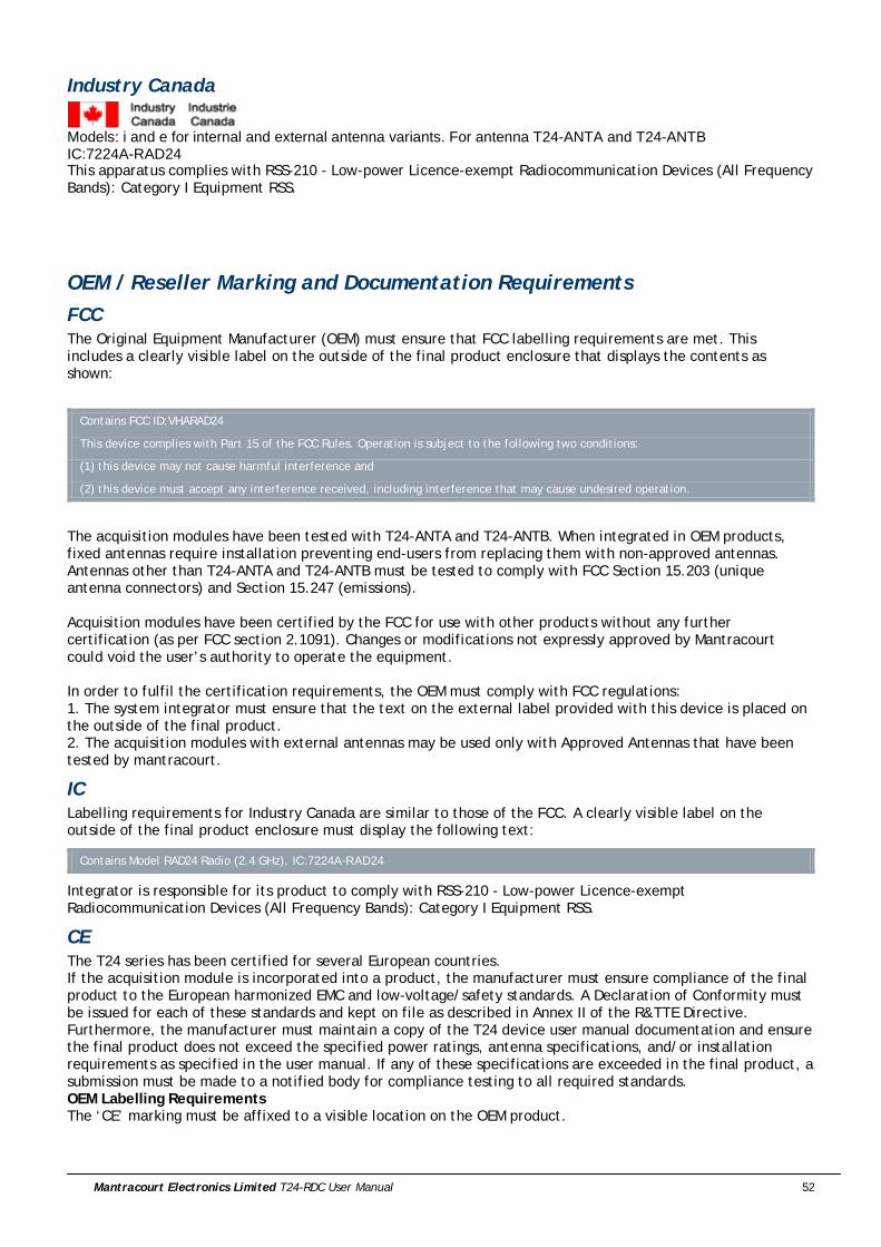
Industry Canada
Models: i and e for internal and external antenna variants. For antenna T24-ANTA and T24-ANTB IC:7224A-RAD24 This apparatus complies with RSS-210 - Low-power Licence-exempt Radiocommunication Devices (All Frequency Bands): Category I Equipment RSS.
OEM / Reseller Marking and Documentation Requirements FCC The Original Equipment Manufacturer (OEM) must ensure that FCC labelling requirements are met. This includes a clearly visible label on the outside of the final product enclosure that displays the contents as shown:
Contains FCC ID:VHARAD24
This device complies with Part 15 of the FCC Rules. Operation is subject to the following two conditions:
(1) this device may not cause harmful interference and
(2) this device must accept any interference received, including interference that may cause undesired operation.
The acquisition modules have been tested with T24-ANTA and T24-ANTB. When integrated in OEM products, fixed antennas require installation preventing end-users from replacing them with non-approved antennas. Antennas other than T24-ANTA and T24-ANTB must be tested to comply with FCC Section 15.203 (unique antenna connectors) and Section 15.247 (emissions). Acquisition modules have been certified by the FCC for use with other products without any further certification (as per FCC section 2.1091). Changes or modifications not expressly approved by Mantracourt could void the user’s authority to operate the equipment. In order to fulfil the certification requirements, the OEM must comply with FCC regulations: 1. The system integrator must ensure that the text on the external label provided with this device is placed on the outside of the final product. 2. The acquisition modules with external antennas may be used only with Approved Antennas that have been tested by mantracourt.
IC Labelling requirements for Industry Canada are similar to those of the FCC. A clearly visible label on the outside of the final product enclosure must display the following text:
Contains Model RAD24 Radio (2.4 GHz), IC:7224A-RAD24
Integrator is responsible for its product to comply with RSS-210 - Low-power Licence-exempt Radiocommunication Devices (All Frequency Bands): Category I Equipment RSS.
CE The T24 series has been certified for several European countries. If the acquisition module is incorporated into a product, the manufacturer must ensure compliance of the final product to the European harmonized EMC and low-voltage/safety standards. A Declaration of Conformity must be issued for each of these standards and kept on file as described in Annex II of the R&TTE Directive. Furthermore, the manufacturer must maintain a copy of the T24 device user manual documentation and ensure the final product does not exceed the specified power ratings, antenna specifications, and/or installation requirements as specified in the user manual. If any of these specifications are exceeded in the final product, a submission must be made to a notified body for compliance testing to all required standards. OEM Labelling Requirements The ‘CE’ marking must be affixed to a visible location on the OEM product.

Mantracourt Electronics Limited T24-RDC User Manual 53
The CE mark shall consist of the initials “CE” taking the following form: If the CE marking is reduced or enlarged, the proportions given in the above graduated drawing must be
respected. The CE marking must have a height of at least 5mm except where this is not possible on account of the
nature of the apparatus. The CE marking must be affixed visibly, legibly, and indelibly.
Mantracourt Electronics Limited T24-RDC User Manual 54
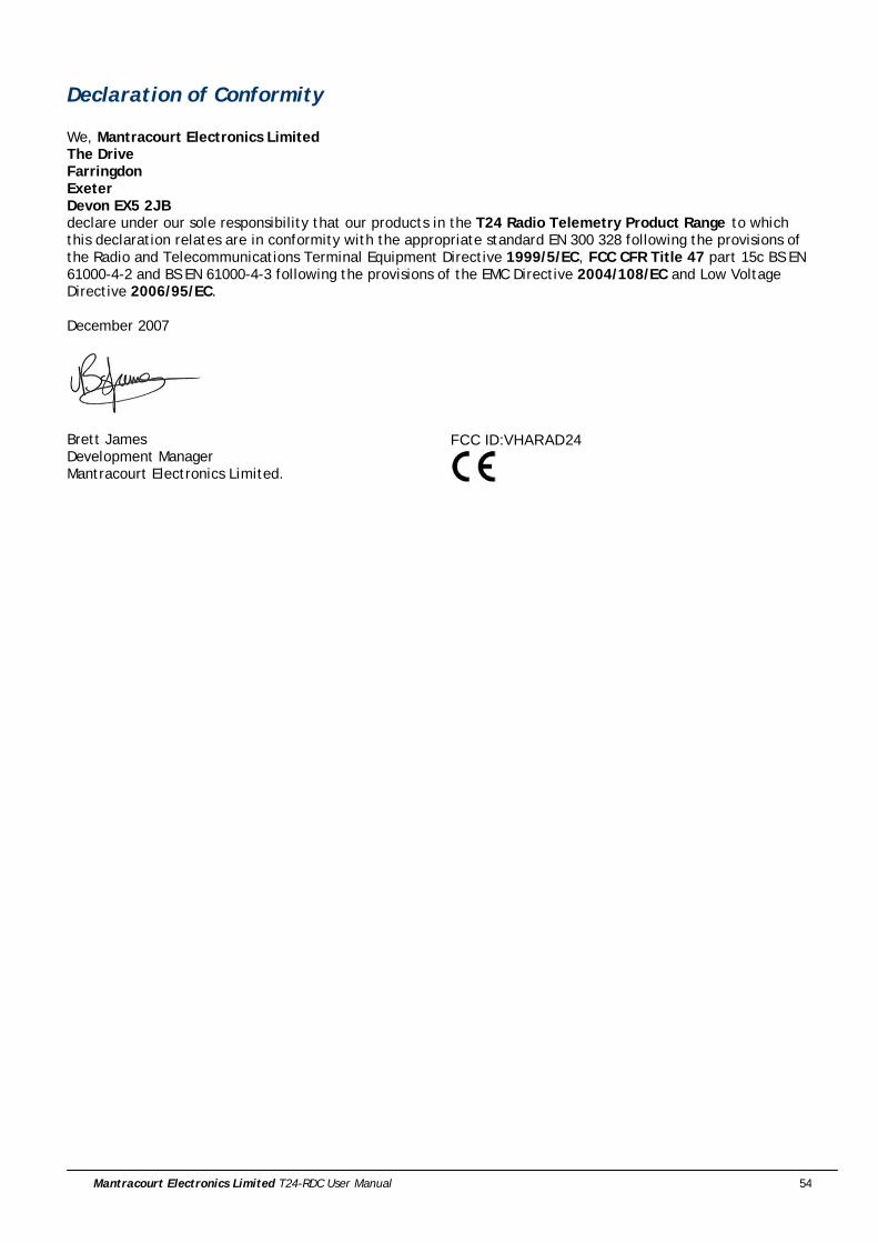
Declaration of Conformity We, Mantracourt Electronics Limited The Drive Farringdon Exeter Devon EX5 2JB declare under our sole responsibility that our products in the T24 Radio Telemetry Product Range to which this declaration relates are in conformity with the appropriate standard EN 300 328 following the provisions of the Radio and Telecommunications Terminal Equipment Directive 1999/5/EC, FCC CFR Title 47 part 15c BS EN 61000-4-2 and BS EN 61000-4-3 following the provisions of the EMC Directive 2004/108/EC and Low Voltage Directive 2006/95/EC. December 2007
Brett James Development Manager Mantracourt Electronics Limited.
FCC ID:VHARAD24

Mantracourt Electronics Limited T24-RDC User Manual 55
Worldwide Regional Approvals Region Product Conforms To Europe CE USA FCC Canada IC Australia To Be Determined China To Be Determined Japan To Be Determined
Important Note Mantracourt does not list the entire set of standards that must be met for each country. Mantracourt customers assume full responsibility for learning and meeting the required guidelines for each country in their distribution market. For more information relating to European compliance of an OEM product incorporating the T24 range of modules, contact Mantracourt, or refer to the following web site: www.ero.dk
Warranty All Telemetry products from Mantracourt Electronics Ltd., ('Mantracourt') are warranted against defective material and workmanship for a period of (1) one year from the date of dispatch. If the 'Mantracourt' product you purchase appears to have a defect in material or workmanship or fails during normal use within the period, please contact your Distributor, who will assist you in resolving the problem. If it is necessary to return the product to 'Mantracourt' please include a note stating name, company, address, phone number and a detailed description of the problem. Also, please indicate if it is a warranty repair. The sender is responsible for shipping charges, freight insurance and proper packaging to prevent breakage in transit. 'Mantracourt' warranty does not apply to defects resulting from action of the buyer such as mishandling, improper interfacing, operation outside of design limits, improper repair or unauthorised modification. No other warranties are expressed or implied. 'Mantracourt' specifically disclaims any implied warranties of merchantability or fitness for a specific purpose. The remedies outlined above are the buyer’s only remedies. 'Mantracourt' will not be liable for direct, indirect, special, incidental or consequential damages whether based on the contract, tort or other legal theory. Any corrective maintenance required after the warranty period should be performed by 'Mantracourt' approved personnel only.
In the interests of continued product development, Mantracourt Electronics Limited reserves the right to alter product specifications without prior notice
Code No. 517-921 Issue 1.2 11.04.14
Related Documents