Remote Control VP04 Pneumatic Proportional Remote Control Valve Catalogue HY17-8356/UK October, 2006

Welcome message from author
This document is posted to help you gain knowledge. Please leave a comment to let me know what you think about it! Share it to your friends and learn new things together.
Transcript
Remote ControlVP04Pneumatic Proportional Remote Control Valve
Catalogue HY17-8356/UKOctober, 2006

� Parker HannifinMobile Controls Division EuropeBorås, Sweden
Remote Control – PneumaticVP04
Catalogue HY17-8356/UK
Conversion factors1 kg = �.�046 lb1 N = 0.��481 lbf1 bar = 14.504 psi1 l = 0.�1997 UK gallon1 l = 0.�6417 US gallon1 cm3 = 0.0610�4 in3
1 m = 3.�808 feet1 mm = 0.03937 in9/5 °C + 3� = °F
This catalogue has been designed to give a brief overview of the VP04, and to make it easy for you to study and choose from the different options available, so that we may customize your remote-control valve in accordance with your wishes. In addition to general information and basic technical data, the brochure therefore contains descriptions of the options available for the valve.
Each function area is given as a subheading, e.g. Connections, followed by a brief description. This is followed by a series of coded options, e.g. M, S, P, T, R, together with a brief description of what each code represents.
The next step is to complete our so-called Customer Specifica-tion Form to specify the options and characteristics you wish to be incorporated into your remote-control valve. When all the control-pressure ports are equal you can specify the valve with the order code at page 5. To specify your valve, simply choose the options you require and enter the corresponding code into the appropriate box in the Customer Specification Form.
Should you require assistance completing the Customer Specification Form or the order code, please do not hesitate to contact your nearest Parker Hannifin representative, who will
either help personally or refer you to the appropriate product specialist.
The information in your Customer Specification Form is then entered into our computerized valve specification program, which initiates the assembly process and generates a unique product ID number that is subsequently stamped into the data plate on your valve, or if you have completed an order code this will be stamped into the plate. Your valve specifications remain on our database to facilitate subsequent re-ordering or servicing of your valve.
Our experienced engineers have in-depth knowledge of the different types of hydraulic system and the ways in which they work. They are at your disposal to offer qualified advice on the best system for the desired combination of functions, control
Catalogue layout
How to order your valve
Early consultation with Parker Hannifin saves time and moneycharacteristics and economic demands. By consulting Parker early in the project planning stage, you are assured of a compre-hensive hydraulic system that gives your machine the best possible operating and control characteristics.
Catalogue Information

3 Parker HannifinMobile Controls Division EuropeBorås, Sweden
Remote Control – PneumaticVP04
Catalogue HY17-8356/UK
Contents
List of contents PageCatalogue Information ....................................................................................................�Conversion factors ..........................................................................................................�General Information ........................................................................................................4Order code ......................................................................................................................5Technical Data ................................................................................................................6Electrical data .................................................................................................................7Breaking capacity ...........................................................................................................7Connections ....................................................................................................................7Weight ............................................................................................................................7Control-pressure characteristic .......................................................................................7Circuit .............................................................................................................................7Control-pressure ports ....................................................................................................8Connection options .........................................................................................................8Lever options ..................................................................................................................8Lever detent options .......................................................................................................8Control-pressure options ................................................................................................8Dimensional drawings .............................................................................................. 9-10
4 Parker HannifinMobile Controls Division EuropeBorås, Sweden
Remote Control – PneumaticVP04
Catalogue HY17-8356/UK
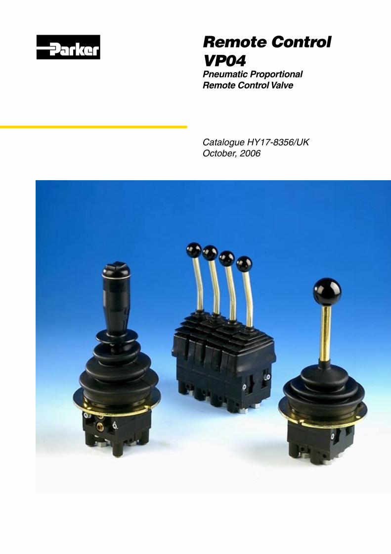
The VPO4 is a stackable, pneumatic control-pressure valve intended for the proportional, pneumatic remote control of directional valves, positioning cylinders etc. It can be supplied with a coordinate lever (joystick) or different linear levers.
Freedom in machine designGood machine design is heavily dependent on the availability of flex-ible components and systems that can be combined in different ways to give optimum operating and control characteristics. Parker Hannifin control systems give you the freedom to design your machines the way you want them, since they themselves are designed to enable components such as directional valves and other control devices to be located ideally on the machine. This gives advantages in production too, since it greatly facilitates the building of machine subassemblies at different sites prior to collation for final assembly.
Moreover, the wide range of Parker Hannifin pneumatic, hydraulic and elec-tric control devices enables optimum design of the machine-control station in terms of ergonomics. (Please see sepa-rate brochures for information about our hydraulic and electric remote-control systems.)
SafetyIn spite of the sophistication of the final functions it may serve, the VP04 remote control valve is of robust and simple construction. This greatly facilitates training and servicing which, together with predictable control characteristics and great dependability, does much to improve the operational safety of the machine.
DesignThe valve is made up of sections, each of which contains two 3-way pressure reducing valves (one per signal port). Up to 8 sections can be stacked together to give a total of 16 signal ports. The valve can be equipped with either one linear lever per section, or with a coordinate lever (joystick) when two sections are stacked to give four signal ports.
Essential characteristics• Low, well adapted operating forces and
short lever strokes give good operator comfort.
• Small dimensions enable simple, compact installation.
• Push-in couplings enable fast, simple connection.
• Low hysteresis ensures consistent pressure output value for a given lever stroke.
• Simple design makes the valve easy to service.
• Quality materials and great precision in manufacturing, assembly and testing assure you of a quality product with low internal leakage and long service life.
• Wide range of control devices and accessories gives great flexibility in system design.
• Total compatibility with Parker Hannifin directional valves gives predictable and harmonious system characteristics.
General Information

5 Parker HannifinMobile Controls Division EuropeBorås, Sweden
Remote Control – PneumaticVP04
Catalogue HY17-8356/UK
See page 7 for further description of different options.
How to order your valveTo specify your valve, simply choose the options you require and enter the corresponding code into the appropriate box in the Customer Specification Form. When all the control-pressure ports are equal you can specify the valve with the order code above.
Should you require assistance completing the Customer Specification Form or the order code, please do not hesitate to contact your nearest Parker Hannifin representative, who will either help personally or refer you to the appropriate product specialist.
Code Connections
M Supply/return ∅8 control ports ∅6
S All ports ∅6
P All ports ∅1/4”
T Supply/return ∅5/16” control ports ∅1/4”
No of control ports
02
04
06
08
10
12
14
16
0-8 bar control- pressure in all ports
Code Lever detent
/ None
MD2 Detent on all ports
A09 Lever H� with neutral position detent
A10 Lever H� with detent in neutral and actuated control port �
A11 Lever H� with detent in neutral and actuated control port 1
Code Lever unit
H1 Coordinate lever
H2 Straight linear lever
H3 Bent linear lever
E1 Linear/coordinate lever � position push-button
E2 Linear/coordinate lever 3 position toggle switch
E3 Linear/coordinate lever 3 position toggle switch with detent at one end
E4 Linear/coordinate lever 3 position toggle switch with detents at both ends
Order code
VP04 — —
Connections Lever unit
Control pressure
Lever detent
—
Control ports
— —
6 Parker HannifinMobile Controls Division EuropeBorås, Sweden
Remote Control – PneumaticVP04
Catalogue HY17-8356/UK
PressureSupply pressure max. 10 bar (145 psi)
(at least � bar higher than max. control pressure)
Control pressure max. 8 bar (116 psi)
Volume rate of flowControl flow at ∆p = 6 bar (87 psi) 7 Nl/s (14.8 cfm free flow)
HysteresisHysteresis max. 1 bar (14.5 psi)
TemperatureMin. ambient temperature -30 °C (86 °F) (assuming dry air or use of agent to reduce freezing-point).Max. ambient temperature +70 °C (158 °F)
Air qualityThe air quality determines the service life of the valve. See ISO 8573.
FilterFiltration max. �0 µm or better
D101755
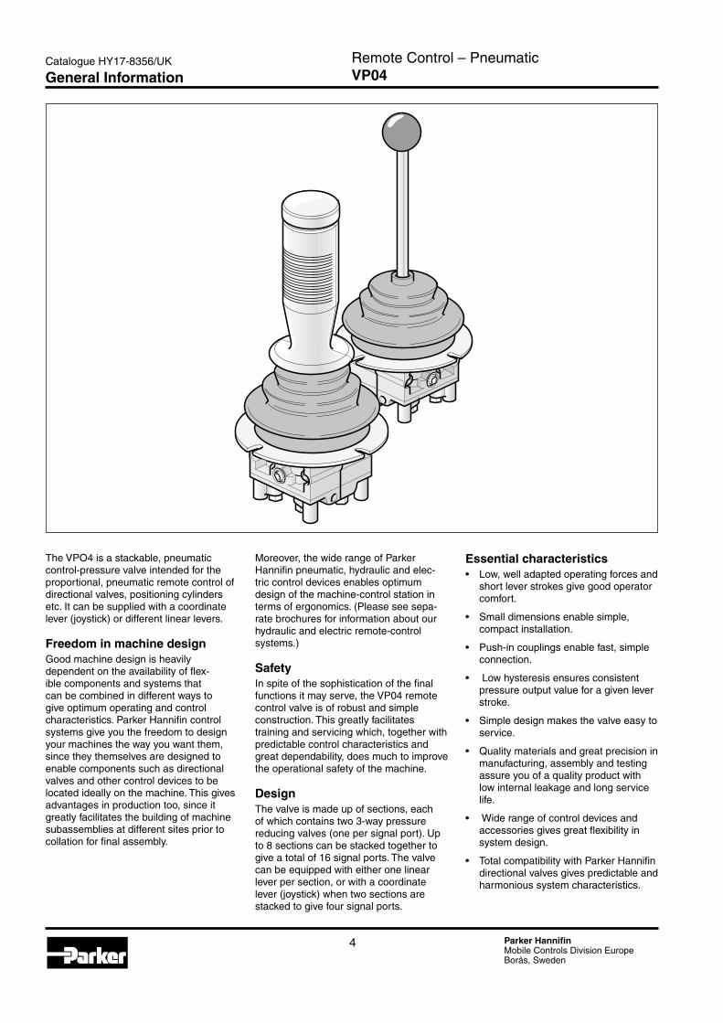
Lever unitBellows
Lever detent MD�
Diaphragm
Regulator unit
Supply connection
Return connection
WarningIf the filtration demands are not met, the valve poppet can jam in the open position, with the result that the valve remains actuated. It is not possible to force back a jammed poppet mechanically.
Lever forcesNormal force for linear lever
fully actuated 3.1 Nm (�.�9 lbf·ft)Normal force for coordinate lever
one function fully actuated 3.9 Nm (�.88 lbf·ft)two functions fully actuated 5.5 Nm (4.06 lbf·ft)
Technical Data
7 Parker HannifinMobile Controls Division EuropeBorås, Sweden
Remote Control – PneumaticVP04
Catalogue HY17-8356/UK
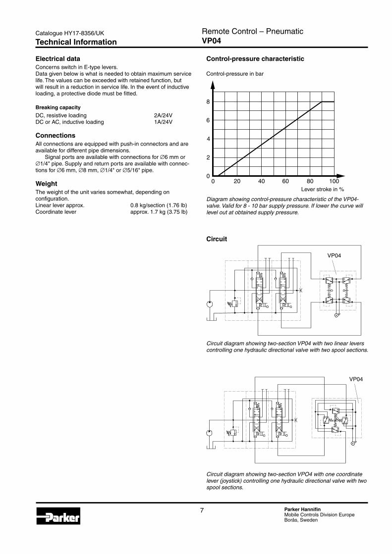
Electrical dataConcerns switch in E-type levers.Data given below is what is needed to obtain maximum service life. The values can be exceeded with retained function, but will result in a reduction in service life. In the event of inductive loading, a protective diode must be fitted.
Breaking capacity
DC, resistive loading �A/�4VDC or AC, inductive loading 1A/�4V
ConnectionsAll connections are equipped with push-in connectors and are available for different pipe dimensions.
Signal ports are available with connections for ∅6 mm or ∅1/4" pipe. Supply and return ports are available with connec-tions for ∅6 mm, ∅8 mm, ∅1/4" or ∅5/16" pipe.
WeightThe weight of the unit varies somewhat, depending on configuration.Linear lever approx. 0.8 kg/section (1.76 lb)Coordinate lever approx. 1.7 kg (3.75 lb)
D101757
D101758
Circuit diagram showing two-section VP04 with two linear levers controlling one hydraulic directional valve with two spool sections.
Circuit diagram showing two-section VPO4 with one coordinate lever (joystick) controlling one hydraulic directional valve with two spool sections.
20 40 60 80 1000
4
6
8
2
0
Control-pressure characteristic
Control-pressure in bar
Lever stroke in %
Diagram showing control-pressure characteristic of the VP04-valve. Valid for 8 - 10 bar supply pressure. If lower the curve will level out at obtained supply pressure.
Circuit
VP04
VP04
Technical Information
8 Parker HannifinMobile Controls Division EuropeBorås, Sweden
Remote Control – PneumaticVP04
Catalogue HY17-8356/UK
Control-pressure ports2-16 Each valve section contains two control-pressure ports.
Two valve sections are needed for coordinate levers (joysticks), since they require 4 control-pressure ports.
Connection optionsM For ∅8 mm pipe in supply and return ports, and ∅6 mm
pipe in the control-pressure ports.
S For ∅6 mm pipe in all ports.
P For ∅1/4" pipe in all ports.
T For ∅5/16" pipe in supply and return ports, and ∅1/4" pipe in the control-pressure ports.
Lever optionsLever units are available in several different versions. For coordi-nate movements (4 control-pressure ports), the H1, E1, E�, E3 and E4 units can be used.
For linear movements (� control-pressure ports), the H�, H3, E1, E�, E3 and E4 units can be used. Owing to the width of the lever unit, only E-levers can be used for valves containing two control-pressure ports, unless a special spacer block is fitted between the sections. E-levers contain a switch that can be used for different external functions.
H1 Coordinate lever (joystick) with ball.
H2 Straight linear lever with ball.
H3 Bent linear lever with ball.
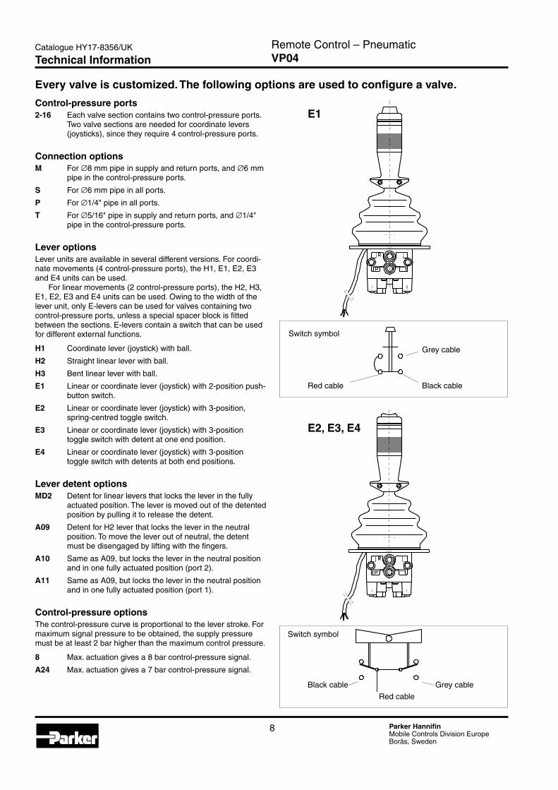
E1 Linear or coordinate lever (joystick) with �-position push-button switch.
E2 Linear or coordinate lever (joystick) with 3-position, spring-centred toggle switch.
E3 Linear or coordinate lever (joystick) with 3-position toggle switch with detent at one end position.
E4 Linear or coordinate lever (joystick) with 3-position toggle switch with detents at both end positions.
Lever detent optionsMD2 Detent for linear levers that locks the lever in the fully
actuated position. The lever is moved out of the detented position by pulling it to release the detent.
A09 Detent for H� lever that locks the lever in the neutral position. To move the lever out of neutral, the detent must be disengaged by lifting with the fingers.
A10 Same as A09, but locks the lever in the neutral position and in one fully actuated position (port �).
A11 Same as A09, but locks the lever in the neutral position and in one fully actuated position (port 1).
Control-pressure optionsThe control-pressure curve is proportional to the lever stroke. For maximum signal pressure to be obtained, the supply pressure must be at least � bar higher than the maximum control pressure.
8 Max. actuation gives a 8 bar control-pressure signal.
A24 Max. actuation gives a 7 bar control-pressure signal.
Every valve is customized. The following options are used to configure a valve.
D101759d
D101759e
E1
Black cable Grey cable
Red cable
E2, E3, E4
Switch symbol
Grey cable
Black cableRed cable
Switch symbol
Technical Information
9 Parker HannifinMobile Controls Division EuropeBorås, Sweden
Remote Control – PneumaticVP04
Catalogue HY17-8356/UK
D101779
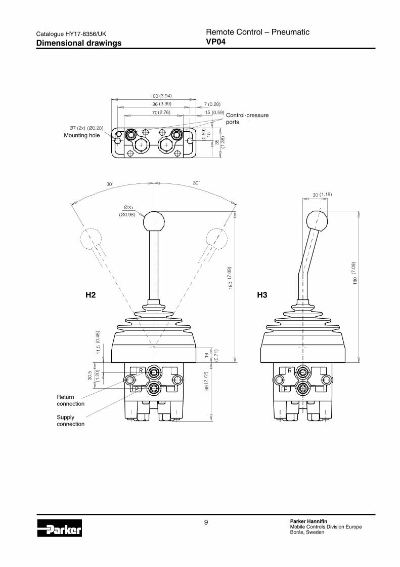
100
86
70
7
15
15
35
Ø7 (2x)
30˚ 30˚
Ø25
180
11,5
30,5
69
180
30
18
(3.94)
(3.39)
(2.76)
(Ø0.28)
(0.28)
(0.59)
(0.5
9)
(1.3
8)
(Ø0.98)
(7.0
9)
(7.0
9)
(1.18)
(0.4
5)(1
.20)
(0.7
1)
(2.7
2)
Control-pressure ports
H2 H3
Return connection
Supply connection
Mounting hole
Dimensional drawings
10 Parker HannifinMobile Controls Division EuropeBorås, Sweden
Remote Control – PneumaticVP04
Catalogue HY17-8356/UK
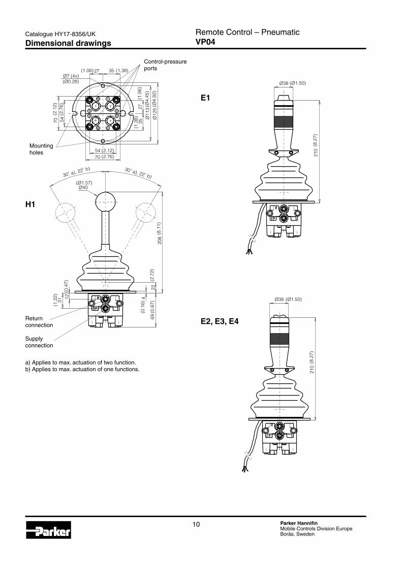
27 35
2735
Ø11
3Ø
125
5470
70 54
Ø40
30˚ a), 22˚ b) 30˚ a), 22˚ b)
3112
69
4
2220
6
D101759a
(Ø1.57)
(1.06) (1.38)
(2.12)(2.76)
(2.1
2)(2
.76)
(1.0
6)(1
.38)
(Ø4.
45)
(Ø4.
92)
(8.1
1)
(0.1
6)
(0.8
7)(2
.72)
(1.2
2)
(0.4
7)
Ø7 (4x)(Ø0.28) Ø38
210
D101759b
(Ø1.50)
(8.2
7)
Ø38
210
D101759c
(8.2
7)
(Ø1.50)
Control-pressure ports
a) Applies to max. actuation of two function.b) Applies to max. actuation of one functions.
H1
E1
E2, E3, E4Return connection
Supply connection
Mounting holes
Dimensional drawings
11 Parker HannifinMobile Controls Division EuropeBorås, Sweden
Remote Control – PneumaticVP04
Catalogue HY17-8356/UK
Offer of SalePlease contact your Parker representation for a detailed ”Offer of Sale”.
FAILURE OR IMPROPER SELECTION OR IMPROPER USE OF THE PRODUCTS AND/OR SYSTEMS DESCRIBED HEREIN OR RELATED ITEMS CAN CAUSE DEATH, PERSONAL INJURY AND PROPERTY DAMAGE.
This document and other information from Parker Hannifin Corporation, its subsidiaries and authorized distributors provide product and/or system options for further investigation by users having technical expertise. It is important that you analyze all aspects of your application, including consequences of any failure, and review the information concerning the product or sys-tem in the current product catalogue. Due to the variety of operating conditions and applications for these products or systems, the user, through its own analysis and testing, is solely responsible for making the final selection of the products and systems and assuring that all performance, safety and warning requirements of the application are met.
The products described herein, including without limitation, product features, specifications, designs, availability and pricing, are subject to change by Parker Hannifin Corporation and its subsidiaries at any time without notice.
WARNING!
Hydraulics GroupSales Offices
InternationalEurope
Catalogue HY17-8356/UKPDF 10/�006
© Copyright �006Parker Hannifin CorporationAll rights reserved.
Parker Hannifin is the world’s premier supplier of motion and control systems and solutions, with sales and manufacturing facilities throughout the world. For product information and details of your nearest Parker sales office, visit us at www.parker.com or call free on 00800 2727 5374.
Austria Wiener NeustadtTel: +43 (0)�6�� �3501Fax: +43 (0)�6�� 66�1�
Austria Wiener Neustadt (Resp for East Europe)Tel: +43 (0)�6�� �3501-970Fax: +43 (0)�6�� �3501-977
Belgium NivellesTel: +3� (0)67 �80 900 Fax: +3� (0)67 �80 999
Czech Republic KlecanyTel: +4�0 �84 083 111 Fax: +4�0 �84 083 11�
Denmark BallerupTel: +45 4356 0400 Fax: +45 4373 3107
Finland VantaaTel: +358 �0 753 �500 Fax: +358 �0 753 ��00
France Contamine-sur-ArveTel: +33 (0)450 �5 80 �5 Fax: +33 (0)450 �5 �4 �5
GermanyKaarstTel: +49 (0)�131 4016 0 Fax: +49 (0)�131 4016 9199
Ireland DublinTel: +353 (0)1 �93 9999 Fax: +353 (0)1 �93 9900
Italy Corsico (MI)Tel: +39 0� 45 19 �1 Fax: +39 0� 4 47 93 40
The Netherlands OldenzaalTel: +31 (0)541 585000 Fax: +31 (0)541 585459
Norway SkiTel: +47 64 91 10 00 Fax: +47 64 91 10 90
Poland WarsawTel: +48 (0)�� 573 �4 00 Fax: +48 (0)�� 573 �4 03
Portugal Leca da PalmeiraTel: +351 �� 9997 360 Fax: +351 �� 9961 5�7
Slovakia Ref. Czech Republic
Spain MadridTel: +34 91 675 73 00 Fax: +34 91 675 77 11
Sweden SpångaTel: +46 (0)8 597 950 00 Fax: +46 (0)8 597 951 10
United Kingdom Warwick Tel: +44 (0)19�6 317 878 Fax: +44 (0)19�6 317 855
Australia Castle HillTel: +61 (0)�-9634 7777 Fax: +61 (0)�-984� 5111
Canada Milton, OntarioTel: +1 905-693-3000 Fax: +1 905-876-0788
China ShanghaiTel: +86 �1 5031 �5�5 Fax: +86 �1 5834 3714
Asia Pacific GroupHong KongTel: +85� �4�8 8008 Fax: +85� �4�5 6896
IndiaMumbaiTel: +91 �� 5613 7081/8�-85 Fax: +91 �� �768 6841/6618
JapanTokyoTel: +(81) 3 6408 3900 Fax: +(81) 3 5449 7�01
Latin America GroupBrazilTel: +55 51 3470 9144 Fax: +55 51 3470 9�81
South Africa Kempton ParkTel: +�7 (0)11-961 0700 Fax: +�7 (0)11-39� 7�13
USACleveland (industrial)Tel: +1 �16-896-3000 Fax: +1 �16-896-4031Lincolnshire (mobile)Tel: +1 847-8�1-1500 Fax: +1 847-8�1-7600
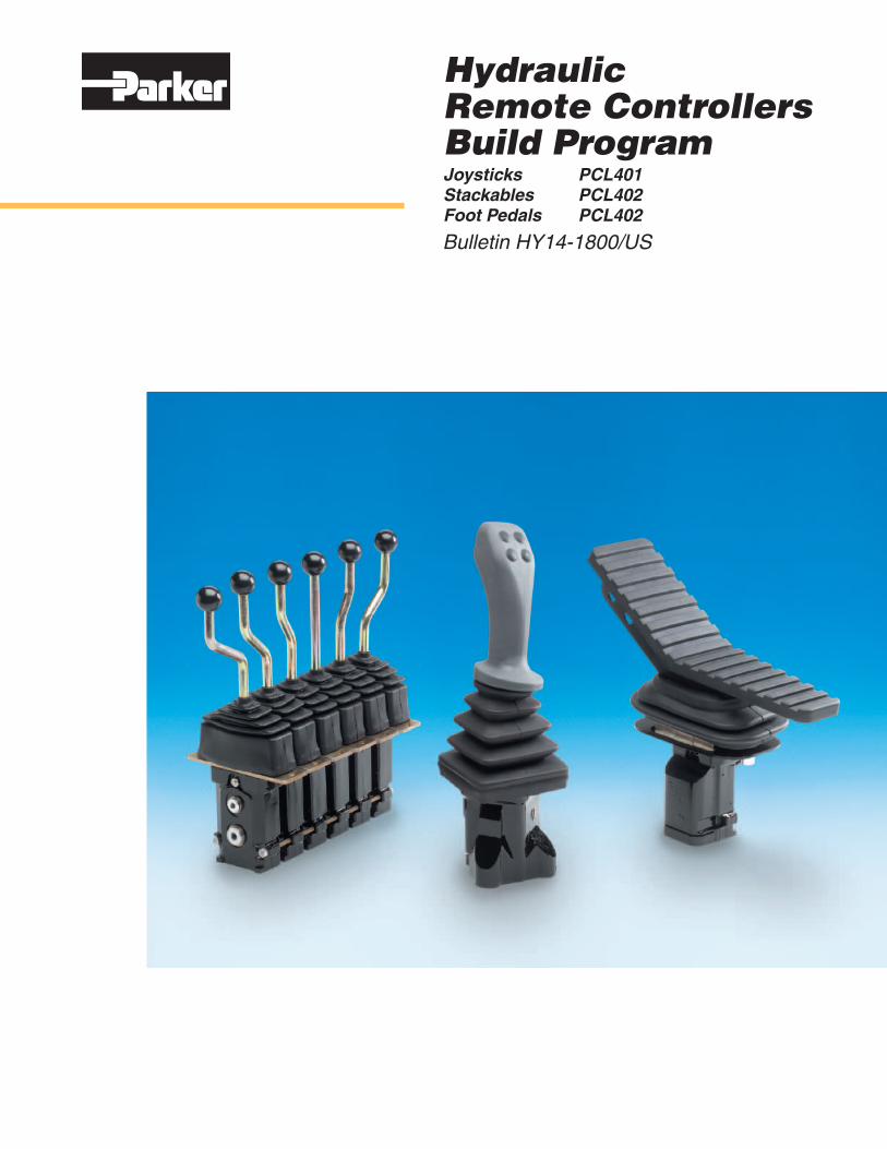
Hydraulic Remote Controllers Build ProgramJoysticks PCL401 Stackables PCL402 Foot Pedals PCL402
Bulletin HY14-1800/US
2 Parker Hannifin CorporationHydraulic Valve DivisionElyria, Ohio, USA
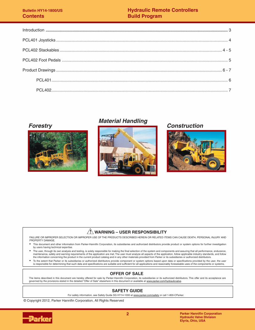
Hydraulic Remote Controllers Build Program
Bulletin HY14-1800/US
Introduction ............................................................................................................................................................. 3
PCL401 Joysticks .................................................................................................................................................... 4
PCL402 Stackables ............................................................................................................................................ 4 - 5
PCL402 Foot Pedals ............................................................................................................................................... 5
Product Drawings ............................................................................................................................................... 6 - 7
PCL401 ........................................................................................................................................................ 6
PCL402 ........................................................................................................................................................ 7
Contents
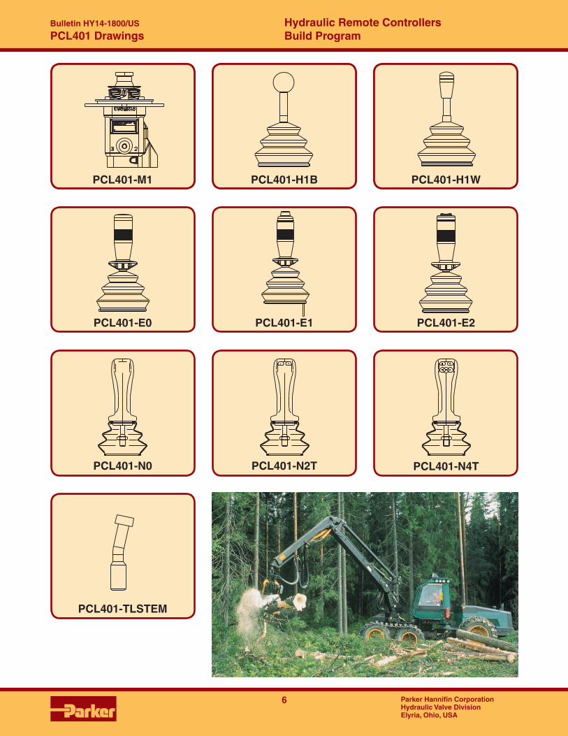
ForestryMaterial Handling
Construction
FAILURE OR IMPROPER SELECTION OR IMPROPER USE OF THE PRODUCTS DESCRIBED HEREIN OR RELATED ITEMS CAN CAUSE DEATH, PERSONAL INJURY AND PROPERTY DAMAGE.
• This document and other information from Parker-Hannifin Corporation, its subsidiaries and authorized distributors provide product or system options for further investigation by users having technical expertise.
• The user, through its own analysis and testing, is solely responsible for making the final selection of the system and components and assuring that all performance, endurance, maintenance, safety and warning requirements of the application are met. The user must analyze all aspects of the application, follow applicable industry standards, and follow the information concerning the product in the current product catalog and in any other materials provided from Parker or its subsidiaries or authorized distributors.
• To the extent that Parker or its subsidiaries or authorized distributors provide component or system options based upon data or specifications provided by the user, the user is responsible for determining that such data and specifications are suitable and sufficient for all applications and reasonably foreseeable uses of the components or systems.
WARNING – USER RESPONSIBILITY
The items described in this document are hereby offered for sale by Parker-Hannifin Corporation, its subsidiaries or its authorized distributors. This offer and its acceptance are governed by the provisions stated in the detailed “Offer of Sale” elsewhere in this document or available at www.parker.com/hydraulicvalve.
© Copyright 2012, Parker Hannifin Corporation, All Rights Reserved
OFFER OF SALE
For safety information, see Safety Guide SG HY14-1000 at www.parker.com/safety or call 1-800-CParker.
SAFETY GUIDE

Parker Hannifin CorporationHydraulic Valve DivisionElyria, Ohio, USA
Bulletin HY14-xxxx/US Hydraulic Remote Controllers Build Program
3
Hydraulic Remote Controllers Build Program
Bulletin HY14-1800/US Hydraulic Remote Controllers Build Program
Bulletin HY14-1800/US Hydraulic Remote Controllers Build Program
Bulletin HY14-1800/US
3 Parker Hannifin CorporationHydraulic Valve DivisionElyria, Ohio, USA
3 Parker Hannifin CorporationHydraulic Valve DivisionElyria, Ohio, USA
Hydraulic Remote Controllers Build Program
Bulletin HY14-1800/US
The basic kits for the program are: • Joysticks and stackables with no handle.
• Handle kits.
• Detent kits.
• Footpedal conversion kits.
• Stud kits.
• Spring pack kits.
• Service kits.
Reference information:
Joysticks – All ports are SAE 6.
– All ports (P,T,1,2,3,4) are located on the bottom of the housing.
– Mounting plate is code M1.
– Boots are included in the handle kits.
Stackables – All ports are SAE 6.
– Pump and tank ports are located on the side of the housing. Ports A&B are located on the bottom of the housing.
– Mounting plate is code M3.
– Boots are included in the handle kits.
Here is a list of documentation available to support this product: PCL4 Catalog HY17-8357/UK
Catalog CD HY14-1800/US – includes the bulletin, the catalog, spare parts list, service and assembly documentation, PowerPoint sales presentation, and DXF engineering drawings.
Parker PCL Build Program
The PCL Build Program is designed to help a stocking distributor increase the value and services offered to their customers. This is accomplished by having the in-house capability of being re-sponsive to your customer’s needs. A wide variety of kits facilitate the conversion and customization of these controllers with a minimun amount of inventory. Joysticks and stackable controllers have custom spring packs that are matched to our control valves and optimize controllability and machine performance. The type of curve selected for the controllers in the program is referred to as “straight-line me-tering”. This means that the “start pressure” and “final pressure” of the controller is linear. Here is a sample of this type of curve.
Introduction
Performance Metering Curve
1.20.05
6.50.26
Spool Stroke (Millimeters)
StartPressure
Metering Curve for code PCL401-U-B-M1-55-270
0
0
20013.8
25017.3
1006.9
15010.4
503.5
30020.7
Bar
(P
SI)
mminches
Bar PSI
Final Pressure(pressure at full stroke)
PCL401 Joystick
PCL402 Foot Pedal

4 Parker Hannifin CorporationHydraulic Valve DivisionElyria, Ohio, USA
Hydraulic Remote Controllers Build Program
Bulletin HY14-1800/US
PCL401 and PCL402
PCL401 Joystick and PCL402 Stackable Controllers
PCL401 Control Valve Match Start Final Part NumberJoystick V10,V11,V20,V26,V42,V50,V56,V70,V86,V90 55 328 PCL401-U-B-M1-55-328Joystick VA/VG20, VA/VG35 & VO40 100 330 PCL401-U-B-M1-100-330Joystick PC25 & PC55 100 410 PCL401-U-B-M1-100-400Joystick F130CF, L90, P70 & VP/VPO/VPL 75 260 PCL401-U-B-M1-75-260Joystick F130CP 90 390 PCL401-U-B-M1-90-390Joystick K170 & K220 80 310 PCL401-U-B-M1-80-310Joystick CI & Gresen controllers metered with Forced Open 50 220 PCL401-U-B-M1-50-220-FOJoystick CI & Gresen controllers metered with Forced Open 100 300 PCL401-U-B-M1-100-300-FO
PCL402 Control Valve Match Start Final Part NumberStackable V10,V11,V20,V26,V42,V50,V56,V70,V86,V90 55 328 PCL402-U-S-M3-55-328Stackable VA/VG20, VA/VG35 & VO40 100 330 PCL402-U-S-M3-100-330Stackable PC25 & PC55 100 400 PCL402-U-S-M3-100-400Stackable F130CF, L90, P70 & VP/VPO/VPL 75 260 PCL402-U-S-M3-75-260Stackable F130CP 90 390 PCL402-U-S-M3-90-390Stackable K170 & K220 80 310 PCL402-U-S-M3-80-310Stackable CI & Gresen controllers metered with Forced Open 50 220 PCL402-U-S-M3-50-220-FOStackable CI & Gresen controllers metered with Forced Open 100 300 PCL402-U-S-M3-100-300-FOStackable None specific. Has bottom P&T ports 55 278 PCL402-U-B-M4-55-275
PCL401 Joystick Handle Kits - Includes standard round boot & loose lead wires for electric switch handles
Description Part NumberPCL401-H1B, Straight ball handle 9120059052PCL401-H1W, Straight handle with knob and removable plastic window 9120089358PCL401-E0, Electric switch handle with no switches 9120089507PCL401-E1, Electric (on/off) switch handle with 2 position thumb switch 9120059053PCL401-E2, Electric (on/off) switch handle with 3 position toggle switch 9120059054PCL401-N0, Electric ergonomic straight handle with no switches 9120089606PCL401-N2T, Electric (on/off) ergonomic straight handle with 2 thumb switches & 1 finger switch 9120089667PCL401-N4T, Electric (on/off) ergonomic straight handle with 4 thumb switches & 1 finger switch 9120089613
PCL401 Handle Conversion KitsFrom/To Part NumberTilt lt/rt stem, PCL401-TLSTEM PCL401-TLSTEMStraight, PCL401-STSTEM PCL401-STSTEM
PCL402 Handle Kits - Includes standard boot and loose leads for electric switch handles
Description Part NumberPCL402-H3-B, Straight ball handle 9120089362PCL402-H4-B, Bent handle with ball knob - .59" offset 9120089363PCL402-H5B, Bent handle with ball knob - 1.18" offset 9120089364PCL402-H6B, Bent handle with ball handle - 1.77" offset 9120089365PCL402-H3-W, Straight handle with knob and removable plastic window 9120089367PCL402-H4-W, Bent handle with knob and removable plastic window - .59" offset 9120089368PCL402-H5-W, Bent handle with knob and removable plastic window - 1.18" offset 9120089369PCL402-H6-W, Bent handle with knob and removable plastic window - 1.77" offset 9120089370PCL402-E0, Electric switch handle with no switches 9120089538PCL402-E1, Electric (on/off) switch handle with 2 position thumb switch 9120089372PCL402-E2, Electric (on/off) switch handle with 3 position thumb switch 9120089373
Pressure Range (psi)
Pressure Range (psi)

Parker Hannifin CorporationHydraulic Valve DivisionElyria, Ohio, USA
Bulletin HY14-xxxx/US Hydraulic Remote Controllers Build Program
5
Hydraulic Remote Controllers Build Program
Bulletin HY14-1800/US Hydraulic Remote Controllers Build Program
Bulletin HY14-1800/US Hydraulic Remote Controllers Build Program
Bulletin HY14-1800/US
5 Parker Hannifin CorporationHydraulic Valve DivisionElyria, Ohio, USA
5 Parker Hannifin CorporationHydraulic Valve DivisionElyria, Ohio, USA
Hydraulic Remote Controllers Build Program
Bulletin HY14-1800/US
PCL402
PCL402 Stackable Controllers
PCL402 Detent Kits (use PCL402 handle kits)Description Part NumberPCL402-MD2, Mechanical detent for ports A&B 9120089614PCL402-S2, Friction detent. (Note: 35mm spacer req'd if another section stacked adjacently) 9120089352PCL402-S2-H, Lever bracket kit for code H type handle 9120089377PCL402-S2-E, Lever bracket kit for code E type handle 9120089378
PCL402 Marine Handle Parts Part NumberPCL402-M3-SS, Mounting plate - Code M3 out of stainless steel 9120089712PCL402-B-SS, Hand Lever - Code B out of stainless steel 9120089713
Spacer Block91262411
Footpedal Kits - converts a standard PCL402 Code F. Steel stamped footpedal with required hardware. Includes M5 mounting plate. Part Number - PCL402-F-PK, Pedal Kit 9120089309 - PCL402-F-MBK, Mounting/Bearing Plate Assembly 9120089310 - PCL402-C6-PPS, C6 spring push pin set 9120089398
Code A36. Cast aluminum footpedal with required hardware. Includes M5 mounting plate. Part Number - PCL402-A36-PK, Pedal Kit 9120089659 - PCL402-A36-MBK, Mounting/Bearing Plate Assembly 9120089660 - PCL402-C6-PPS, C6 spring push pin set 9120089398
Stud Kits (includes seals) Part NumberPCL402-2-SK, 2 sections 9120089359PCL402-3-SK, 3 sections 9120089303PCL402-4-SK, 4 sections 9120089304PCL402-5-SK, 5 sections 9120089305PCL402-6-SK, 6 sections 9120089306
Spring Packs Start Final Part NumberSP-55-328-SL, V10, V11, V20, V26, V42, V50, V56, V70, V86, V90 55 328 9126181859SP-100-330-SL, VA/VG20, VA/VG35 & VO40 100 330 9126181824SP-100-410-SL, PC25, PC55 100 410 9126181825SP-75-260-SL, F130CF, L90, P70 75 260 9126181826SP-90-400-SL, F130CP 75 400 9126181827SP-80-310-SL, K170, K220 80 310 9126181828
Matches curve for former CI & Gresen controllers 50 220 9126181830-FOMatches curve for former CI controllers 100 300 9126181815-FO
Service Kits Part Number - Push pin seal kit (1 kit needed for each push pin) 9120089332 - PCL402 section seal (2 needed per section) 06636127 - PCL402 plug kit (needed to plug side P&T UNF ports) 9120089329 - PCL402 pin/bushing kit for A36 footpedal 9120089661 - Cable 3/0.34/650 MM, for code E handles, no connector 9120089681 - Cable assembly N2T, no connector 9120089683 - Cable assembly N2, no connector 9120089684 - Cable assembly N4, no connector 9120089685 - Cable assembly N4T, no connector 9120089686 - Cable assembly N4T, Deutch/640 MM 9120089687 - Cable assembly N4T, Deutch/900 MM 9120089688 - Shim Kit (4000 total pieces) 20016558
35mm wide. Same as PCL402 section width. Does not include section seals.
6 Parker Hannifin CorporationHydraulic Valve DivisionElyria, Ohio, USA
Hydraulic Remote Controllers Build Program
Bulletin HY14-1800/US
PCL401 Drawings
PCL401-H1B
PCL401-E0
PCL401-H1W
PCL401-E1 PCL401-E2
PCL401-N0 PCL401-N2T PCL401-N4T
PCL401-TLSTEM
PCL401-M1
1
3 5 4
2
Parker Hannifin CorporationHydraulic Valve DivisionElyria, Ohio, USA
Bulletin HY14-xxxx/US Hydraulic Remote Controllers Build Program
7
Hydraulic Remote Controllers Build Program
Bulletin HY14-1800/US Hydraulic Remote Controllers Build Program
Bulletin HY14-1800/US Hydraulic Remote Controllers Build Program
Bulletin HY14-1800/US
7 Parker Hannifin CorporationHydraulic Valve DivisionElyria, Ohio, USA
7 Parker Hannifin CorporationHydraulic Valve DivisionElyria, Ohio, USA
Hydraulic Remote Controllers Build Program
Bulletin HY14-1800/US
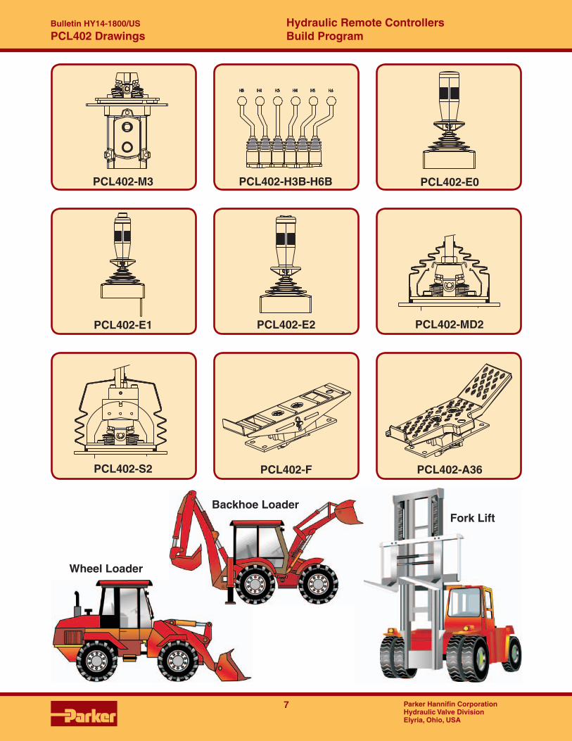
Fork Lift
Wheel Loader
PCL402 Drawings
PCL402-MD2
PCL402-S2 PCL402-A36PCL402-F
PCL402-E2PCL402-E1
PCL402-E0PCL402-M3 PCL402-H3B-H6B
H5 H4 H3 H5H4 H6
Backhoe Loader

Your Local Authorized Parker Distributor
Bulletin HY14-1800/US, 3/12
Parker Hannifin CorporationHydraulic Valve Division520 Ternes AvenueElyria, Ohio 44035 USATel: 440-366-5100Fax: 440-366-5253www.parker.com/hydraulicvalve
© 2012 Parker Hannifin Corporation
Parker Hydraulics International Sales Offices
North AmericaHydraulics Group Headquarters6035 Parkland Boulevard Cleveland, OH 44124-4141 USA Tel: 216-896-3000 Fax: 216-896-4031
Parker Canada Division160 Chisholm Drive Milton, Ontario, L9T 3G9 Canada Tel: 905-693-3000 Fax: 905-876-1958
Mexico Parker Hannifin de MéxicoIndustrial Hydraulic Sales Eje Uno Norte No. 100 Parque Industrial Toluca 2000 Toluca, Edo. de Mexico CP 50100 Tel: 52 72 2275 4200 Fax: 52 72 2279 9308
EuropeHydraulics Group Headquarters La Tuilière 6CH-1163 Etoy, SwitzerlandTel: 41 21 821 8500Fax: 41 21 821 8580
Latin AmericaParker Hannifin Ind. e Com. Ltda Hydraulics DivisionAv. Frederico Ritter, 110094930-000 Cachoeirinha RS, Brazil Tel: 55 51 3470 9144 Fax: 55 51 3470 9215
Parker Hannifin Argentina S.A.I.C.Stephenson 27111667-Tortuguitas-Malvinas ArgentinasPcia. de Buenos Aires, Argentina Tel: 54 3327 44 4129 Fax: 54 3327 44 4199
Pan American Division7400 NW 19th Street, Suite A Miami, FL 33126 USA Tel: 305-470-8800 Fax: 305-470-8808
Industrial SalesCentral Region1042 Maple AvenueUnit 331Lisle, IL 60532 USATel: 630-964-0796
Great Lakes Region6035 Parkland Boulevard Cleveland, OH 44124-4141 USA Tel: 216-896-3000Fax: 216-896-4031
Gulf Region20002 Standing Cypress DriveSpring, TX 77379 USATel: 817-473-4431Fax: 888-227-9454
Southwest Region700 S. 4th AvenueMansfield, TX 76063 USATel: 817-473-4431Fax: 888-227-9454
Mid Atlantic & Southeast Regions1225 Old Alpharetta Rd Suite 290Alpharetta, GA 30005 USATel: 770-619-9767Fax: 770-619-9806
Midwest Region8145 Lewis RoadMinneapolis, MN 55427 USATel: 763-513-3535Fax: 763-544-3418
Northeast RegionP.O. Box 396Pine Brook, NJ 07058 USATel: 973-227-2565Fax: 973-227-2467
Northwest Region6458 North Basin Avenue Portland, OR 97217 USATel: 503-283-1020Fax: 866-611-7308
Pacific and Plains Region8460 Kass DriveBuena Park, CA 90621 USATel: 714-228-2509Fax: 714-228-2511
Mobile SalesMobile Sales Organization and Global Sales850 Arthur AvenueElk Grove Village, IL 60007 USATel: 847-258-6200Fax: 847-258-6299
Asia PacificParker Hannifin Shanghai Ltd.280 Yunqiao Road, Jin Qiao Export Processing Zone Shanghai 201206, China Tel: 86 21 2899 5000 Fax: 86 21 5834 8975
Parker Hannifin Hong Kong Ltd.Suites 01-04, 20/F,Tower 2, The Gateway, Harbour City, Tsimshatsui, Hong Kong Tel: 852 2428 8008 Fax: 852 2480 4256
Parker Hannifin Korea Ltd.18F KAMCO Yangjae Tower 949-3 Dogok1-dong, Gangnam-gu Seoul, 135-860, Korea Tel: 82 2 559 0408 Fax: 82 2 556 8187
Parker Hannifin India Pvt Ltd.Plot No. EL-26, MIDC, TTC Industrial Area Mahape, Navi Mumbai, 400 709, India Tel: 91 22 6513 7081 Fax: 91 22 2768 6841
Parker Hannifin AustraliaParker Hannifin Pty Ltd.9 Carrington Road Castle Hill, NSW 2154, Australia Tel: 612 9634 7777 Fax: 612 9842 5111
South AfricaParker Hannifin Africa Pty Ltd10 Berne AvenueAeroport Kempton Park 1620, Republic of South Africa Tel: 19 610 700 Fax: 13 927 213
Related Documents