ISSN: 2180-1843 e-ISSN: 2289-8131 Vol. 8 No. 12 53 Remote AC Power Control by Using Microcontroller Lee Siang Tat, Yiauw Kah Haur Department of Electrical and Electronics Engineering, Faculty of Engineering and Build Environment, Tunku Abdul Rahman University College, Kuala Lumpur, Malaysia. [email protected] Abstract—AC power control is already existed in our daily lifestyle but there are some limitations for presence control technology, such as some AC power control devices could not control remotely and provide limited power controlling range. To improve presence power control technology, this paper presented a phase control method implemented on Arduino microcontroller to control power delivered to AC loads by using TRIAC. In this paper, a lamp load is used as the AC load. Moreover, wireless remote technology based on Bluetooth is used to control the AC loads. Thus, users are able to control the AC loads with a Bluetooth enabled smartphone as graphical user interface (GUI). This system has provided a convenient solution to control AC load wirelessly which required only a smartphone as GUI. Furthermore, the response of the developed remote AC power control system is compared with a conventional dimmer switch available in market. Index Terms—AC Load; Android; Arduino; Phase Control Method. I. INTRODUCTION Controlling AC power (like switch on/off, change brightness of lamp, control fan speed etc.) is not a new thing, it is already existed in our daily lifestyle. However, existing AC power controlling is inconvenience as user required to go near to the appliance to control the device. Therefore, controlling AC power remotely is becoming the trend when the concept of Internet of Things (IoT) is becoming an increasingly growing conversation topic in the world. IoT enables embedded system, hand phone, electrical appliances, software, sensors etc. to collect and exchange data wirelessly. Bluetooth technology is one of the best way to implement IoT [14]. Wireless remote AC power control provides much of benefits such as extended range, elimination the need for wire, less maintenance, provide safety and reliable. Lamp, heater, and AC induction motor are the most common electrical appliances in this modern world. These AC loads could be found at every residence house and industry area. Greatest interest of this paper is on controlling the power on AC load by Arduino microcontroller via Bluetooth. An Android app is developed to enable users to control the electrical appliances through Bluetooth. A circuit has been developed where the Arduino microcontroller is connected to opto-isolators, TRIAC and Bluetooth device. Varying the root means square (rms) value of voltage supply resulting in varying of power delivered to the AC loads [8]. Varying the rms value of supply voltage could be done by using a TRIAC [12]. TRIAC is a bidirectional silicon controlled rectifier (SCR) or thyristor. Unlike SCR, TRIAC could conduct current in both directions which makes them convenient to regulate the AC voltage. Figure 1 shows TRIAC output voltage waveform. Figure 1: TRIAC Output Voltage Waveform The load rms voltage is same as the TRIAC’s output rms voltage. The TRIAC’s output rms voltage is related to delay angle, α [15] which is represented as: (1) where: () = TRIAC rms output voltage = Supply voltage α = delay angle, in radian II. BACKGROUND AND LITERATURE REVIEW Arduino [2, 13] is convenient to use to create electronics and electrical prototypes. It is based on open-source prototyping platform that provide easy-to-use features both in hardware and software. Although there are many types of Arduino microcontroller in the market, Arduino Uno R3 microcontroller is using as the main microcontroller in this paper for its robust features. Arduino Uno is based on the ATmega328P, running on 16MHz, and provide a serial port for develop communication between devices and Arduino, such as Bluetooth module, Wi-Fi module, sensors module, keypad, computer, other microcontroller etc. There are much of propose methods to control AC loads. The proposed method could be improved by implementing Bluetooth technology. Users could control the AC loads from the Android smartphone as GUI via Bluetooth. To implement the Bluetooth technology on the Arduino microcontroller, HC-05 module is used in the system. HC-05 module is a Bluetooth module, designed for Bluetooth serial CORE Metadata, citation and similar papers at core.ac.uk Provided by Universiti Teknikal Malaysia Melaka: UTeM Open Journal System

Welcome message from author
This document is posted to help you gain knowledge. Please leave a comment to let me know what you think about it! Share it to your friends and learn new things together.
Transcript
ISSN: 2180-1843 e-ISSN: 2289-8131 Vol. 8 No. 12 53
Remote AC Power Control by Using Microcontroller
Lee Siang Tat, Yiauw Kah Haur
Department of Electrical and Electronics Engineering, Faculty of Engineering and Build Environment,
Tunku Abdul Rahman University College, Kuala Lumpur, Malaysia.
Abstract—AC power control is already existed in our daily
lifestyle but there are some limitations for presence control
technology, such as some AC power control devices could not
control remotely and provide limited power controlling range. To
improve presence power control technology, this paper presented
a phase control method implemented on Arduino microcontroller
to control power delivered to AC loads by using TRIAC. In this
paper, a lamp load is used as the AC load. Moreover, wireless
remote technology based on Bluetooth is used to control the AC
loads. Thus, users are able to control the AC loads with a Bluetooth
enabled smartphone as graphical user interface (GUI). This
system has provided a convenient solution to control AC load
wirelessly which required only a smartphone as GUI.
Furthermore, the response of the developed remote AC power
control system is compared with a conventional dimmer switch
available in market.
Index Terms—AC Load; Android; Arduino; Phase Control
Method.
I. INTRODUCTION
Controlling AC power (like switch on/off, change brightness of
lamp, control fan speed etc.) is not a new thing, it is already
existed in our daily lifestyle. However, existing AC power
controlling is inconvenience as user required to go near to the
appliance to control the device. Therefore, controlling AC
power remotely is becoming the trend when the concept of
Internet of Things (IoT) is becoming an increasingly growing
conversation topic in the world. IoT enables embedded system,
hand phone, electrical appliances, software, sensors etc. to
collect and exchange data wirelessly. Bluetooth technology is
one of the best way to implement IoT [14].
Wireless remote AC power control provides much of benefits
such as extended range, elimination the need for wire, less
maintenance, provide safety and reliable.
Lamp, heater, and AC induction motor are the most common
electrical appliances in this modern world. These AC loads
could be found at every residence house and industry area.
Greatest interest of this paper is on controlling the power on AC
load by Arduino microcontroller via Bluetooth. An Android app
is developed to enable users to control the electrical appliances
through Bluetooth. A circuit has been developed where the
Arduino microcontroller is connected to opto-isolators, TRIAC
and Bluetooth device.
Varying the root means square (rms) value of voltage supply
resulting in varying of power delivered to the AC loads [8].
Varying the rms value of supply voltage could be done by using
a TRIAC [12]. TRIAC is a bidirectional silicon controlled
rectifier (SCR) or thyristor. Unlike SCR, TRIAC could conduct
current in both directions which makes them convenient to
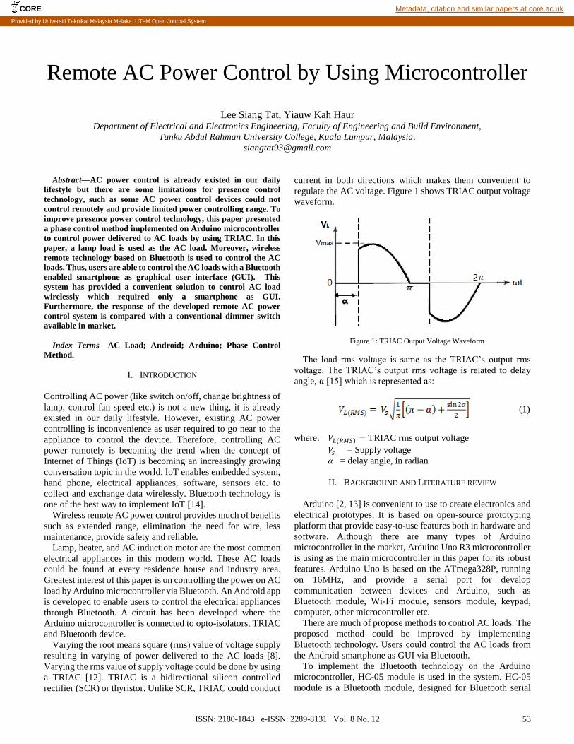
regulate the AC voltage. Figure 1 shows TRIAC output voltage
waveform.
Figure 1: TRIAC Output Voltage Waveform
The load rms voltage is same as the TRIAC’s output rms
voltage. The TRIAC’s output rms voltage is related to delay
angle, α [15] which is represented as:
(1)
where: 𝑉𝐿(𝑅𝑀𝑆) = TRIAC rms output voltage
𝑉𝑠 = Supply voltage
α = delay angle, in radian
II. BACKGROUND AND LITERATURE REVIEW
Arduino [2, 13] is convenient to use to create electronics and
electrical prototypes. It is based on open-source prototyping
platform that provide easy-to-use features both in hardware and
software. Although there are many types of Arduino
microcontroller in the market, Arduino Uno R3 microcontroller
is using as the main microcontroller in this paper for its robust
features. Arduino Uno is based on the ATmega328P, running
on 16MHz, and provide a serial port for develop
communication between devices and Arduino, such as
Bluetooth module, Wi-Fi module, sensors module, keypad,
computer, other microcontroller etc.
There are much of propose methods to control AC loads. The
proposed method could be improved by implementing
Bluetooth technology. Users could control the AC loads from
the Android smartphone as GUI via Bluetooth.
To implement the Bluetooth technology on the Arduino
microcontroller, HC-05 module is used in the system. HC-05
module is a Bluetooth module, designed for Bluetooth serial
CORE Metadata, citation and similar papers at core.ac.uk
Provided by Universiti Teknikal Malaysia Melaka: UTeM Open Journal System

Journal of Telecommunication, Electronic and Computer Engineering
54 ISSN: 2180-1843 e-ISSN: 2289-8131 Vol. 8 No. 12
connection setup [5]. Compared to other Bluetooth module,
HC-05 is a more capable module as it could be either master or
slave device, which make HC-05 not only transmitting
Bluetooth signal but also a receiver. It is used to build up the
Bluetooth connection between the Arduino microcontroller and
the Android based smartphone.
Android is a famous mobile operating system (OS) currently
developed by Google. Android is open source which enables
the manufacturers and developers to extend the functionality of
devices by modify the OS or writing applications (app). As of
third quarter of 2015, 84.7% smartphone market share is
dominated by Android smartphone [9]. Thus, Android is chosen
as the main platform to develop the GUI app to benefit most of
the smartphone user. In fact, any Bluetooth controller app could
be used as the GUI. However, to improve the convenience,
Android Studio developed by Google is using to construct the
GUI to let user to control the AC loads [6]. Android Studio is
an integrated development environment (IDE) for Android app
development [7]. After constructing the GUI, the Android
application package (apk) file will be released from the Android
Studio and be installed on Android based smartphone. The
Android app is acted as GUI for user to control the AC loads.
A. Identification of Problems
Controlling electrical appliances manually is inconvenient
that the users are required to move near to the electrical
appliances to control it. Therefore, controlling the electrical
appliances wirelessly could be a solution for this problem.
Remote AC power control not only provide convenience, but
also provide safety that reduce the risk that the controlling
devices are damaged or in worst case, users get electrical shock.
One of the problem of existing remote controller is the remote
controller is needed to point directly to the infrared receiver on
the devices [11]. Remote controller also provide limited range
of effective controlling distance between the controller and the
devices’ receiver. A better solution is using smartphone app to
allow user to control electrical appliances via Bluetooth
technology. Bluetooth technology provide a wider effective
controlling range between devices, it have a range up to 10m
between devices [17]. Also, most of the smartphone nowadays
have built-in Bluetooth feature. Instead of only switch on and
off, the app should enable user to control AC power delivered
to the electrical appliances, such like controlling the brightness
of lamp [4].
Furthermore, much of the AC control system available in the
market, such as dimmer, provide a limited range of power
controlling on AC load. Thus, a better power control system in
terms of wider range of power controlling with wireless
technology is necessary to provide convenient and acceptable
power control range.
III. AIM AND OBJECTIVES
The main focus in this paper is to improve the presence AC
power control system to more convenient system in terms of
control AC loads remotely and provide wider power controlling
range.
IV. METHODOLOGY
The power delivered to the AC loads is directly proportional
to the rms voltage supply. Since socket’s supply voltage on wall
is always fixed, phase control technique could use to adjust the
rms value of the supply voltage to the AC loads. The whole
implemented circuit is shown in Figure 2.
Figure 2: Phase Control Technique Circuit Diagram
The main circuit could separate to two parts, zero-crossing
detector and AC load driver circuit. The zero-crossing detector
[1] is the upper part with optocoupler, bridge rectifier, and two
current limiting resistors. While the lower part is the AC load
driver constructed by TRIAC, MOC3020 optocoupler with 2
resistors (360Ω and 470Ω). For inductive load (such as motor),
resistors-capacitors (RC) combined snubber circuit is added in
the circuit and connected parallel across the TRIAC, with 39Ω
resistor and 0.01μF capacitor. The snubber circuit is excluded
in the figure as resistive load is used in this paper. The main
purpose of snubber circuit is to improve the TRIAC’s switching
behavior on inductive load, such as induction motor [16]. The
HC-05 Bluetooth module is connected to the serial port on the
Arduino Uno microcontroller.
In the phase control technique implemented, Arduino is
programmed to fire the gate pulses to TRIAC for a number of
microseconds after a period of time the main supply voltage
cross zero. Therefore, a zero crossing detector (ZCD) is
necessary to detect when the sinusoidal supply voltage goes
through zero [1]. This could avoid unpredictable time for
TRIAC conducts or in other words, during what part of the
sinusoidal wave the TRIAC is turn on and lead to unpredictable
power of loads. The pulses generated by the ZCD acts as
interrupt signals to the Arduino microcontroller [18]. Arduino
microcontroller is then firing a pulse to the TRIAC. By
controlling the time delay between zero crossing point and
firing gate pulses to TRIAC, power delivered to the AC load is
controlled smoothly and effectively. To protect the Arduino
microcontroller being damaged by high voltage, an optocoupler
MOC3020 is placed in between the microcontroller and TRIAC
to isolate the high voltage side of loads and low voltage side of
the Arduino microcontroller.
A. Measuring Methods
A dimmable 240 V light bulb is using as the AC load to
demonstrate the functionality of the system. The illuminance of
the lamp is measured using a lux meter (Extech LT45) as shown
as in Figure 3. The distance between the lamp and the lux meter

Remote AC Power Control by Using Microcontroller
ISSN: 2180-1843 e-ISSN: 2289-8131 Vol. 8 No. 12 55
is fixed at 8 cm for every data taken. All data is taken at dark
environment (illuminance below 10 lux) to maintain accuracy.
Figure 3: Illuminance of Lamp is measured by Lux Meter
To measure the load rms voltage, a Tektronix TDS2014B
digital storage oscilloscope with differential probe is using to
measure the actual time delay, t as shown as in Figure 4. The
delay time measured is then convert to delay angle using
equation as shown:
Delay angle, α = (2)
10 ms is using in the equation as the frequency of the voltage
supply is 50 Hz. The delay angle, α is then convert to radian and
been used to calculate the load rms voltage using Equation (1)
with measured voltage supply.
Figure 4: Measuring Exact Delay Time
To make comparison of the method implemented on the
Arduino microcontroller with a normal dimmer available in
market, a phase-angle control dimmer switch (Promark 9008)
is using to compare the behaviour of the method implemented
on Arduino microcontroller.
V. SOFTWARE IMPLEMENTATION
The method implemented in this paper is coding on Arduino
Uno microcontroller using Arduino Software. The flowchart of
the coding is shown at Figure 5.
Figure 5: Arduino Coding Flow Chart
Determining the required time delay of sending triggering
pulses to TRIAC after the zero-crossing is the most crucial part.
The delayed time is according to the Bluetooth Serial input. To
determine the time delay, first it is a need to aware of the
frequency of the supply voltage. In this paper, 50 Hz supply
voltage is used, which means that every 10 ms, the supply
voltage will cross zero point. The step resolution used is 64
steps, which means that every step is around 150 μs. Thus, the
total delay time required is 150 μs multiply with Bluetooth
serial input (1 to 64).
Before trigger the TRIAC, it is a need to check whether the
Bluetooth serial input is a number and lies in the range of 0 to
64 to avoid weird result (such like flickering on lamp load). The
last step in the flowchart is to stop trigger the TRIAC after 10
μs. In fact, it is only remove the triggering signal to the TRIAC,
the TRIAC still conduct current until next zero-crossing point.
Removing the triggering signal is to make sure no accidental
ignition of TRIAC is occurred before the delay time in next
cycle [3].
VI. RESULTS
The AC load rms voltage is varied as the step input varying.
In Figure 6, there are two graphs plotted, practical and ideal
cases load rms voltage vs step percentage. As 64 steps is using
in this paper, each step input is divided by 64 to get the
percentage value. The graphs are showing that the increases of
Journal of Telecommunication, Electronic and Computer Engineering
56 ISSN: 2180-1843 e-ISSN: 2289-8131 Vol. 8 No. 12
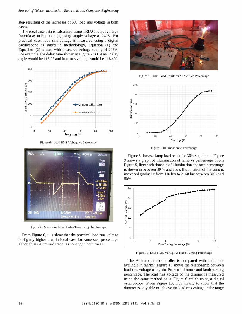
step resulting of the increases of AC load rms voltage in both
cases.
The ideal case data is calculated using TRIAC output voltage
formula as in Equation (1) using supply voltage as 240V. For
practical case, load rms voltage is measured using a digital
oscilloscope as stated in methodology, Equation (1) and
Equation (2) is used with measured voltage supply of 243V.
For example, the delay time shown in Figure 7 is 6.4 ms, delay
angle would be 115.2° and load rms voltage would be 118.4V.
Figure 6: Load RMS Voltage vs Percentage
Figure 7: Measuring Exact Delay Time using Oscilloscope
From Figure 6, it is show that the practical load rms voltage
is slightly higher than in ideal case for same step percentage
although same upward trend is showing in both cases.
Figure 8: Lamp Load Result for ‘30%’ Step Percentage
Figure 9: Illumination vs Percentage
Figure 8 shows a lamp load result for 30% step input. Figure
9 shows a graph of illumination of lamp vs percentage. From
Figure 9, linear relationship of illumination and step percentage
is shown in between 30 % and 85%. Illumination of the lamp is
increased gradually from 110 lux to 2160 lux between 30% and
85%.
Figure 10: Load RMS Voltage vs Knob Turning Percentage
The Arduino microcontroller is compared with a dimmer
available in market. Figure 10 shows the relationship between
load rms voltage using the Promark dimmer and knob turning
percentage. The load rms voltage of the dimmer is measured
using the same method as in Figure 6 which using a digital
oscilloscope. From Figure 10, it is clearly to show that the
dimmer is only able to achieve the load rms voltage in the range
Remote AC Power Control by Using Microcontroller
ISSN: 2180-1843 e-ISSN: 2289-8131 Vol. 8 No. 12 57
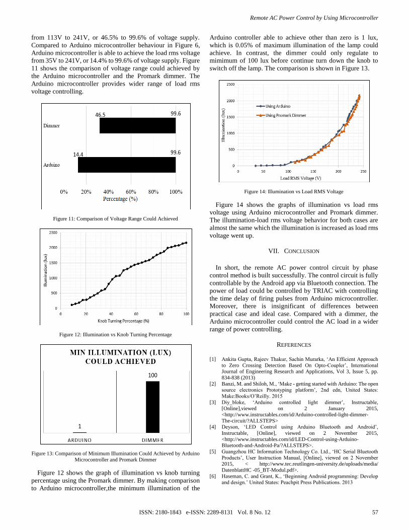
from 113V to 241V, or 46.5% to 99.6% of voltage supply.
Compared to Arduino microcontroller behaviour in Figure 6,
Arduino microcontroller is able to achieve the load rms voltage
from 35V to 241V, or 14.4% to 99.6% of voltage supply. Figure
11 shows the comparison of voltage range could achieved by
the Arduino microcontroller and the Promark dimmer. The
Arduino microcontroller provides wider range of load rms
voltage controlling.
Figure 11: Comparison of Voltage Range Could Achieved
Figure 12: Illumination vs Knob Turning Percentage
Figure 13: Comparison of Minimum Illumination Could Achieved by Arduino
Microcontroller and Promark Dimmer
Figure 12 shows the graph of illumination vs knob turning
percentage using the Promark dimmer. By making comparison
to Arduino microcontroller,the minimum illumination of the
Arduino controller able to achieve other than zero is 1 lux,
which is 0.05% of maximum illumination of the lamp could
achieve. In contrast, the dimmer could only regulate to
mimimum of 100 lux before continue turn down the knob to
switch off the lamp. The comparison is shown in Figure 13.
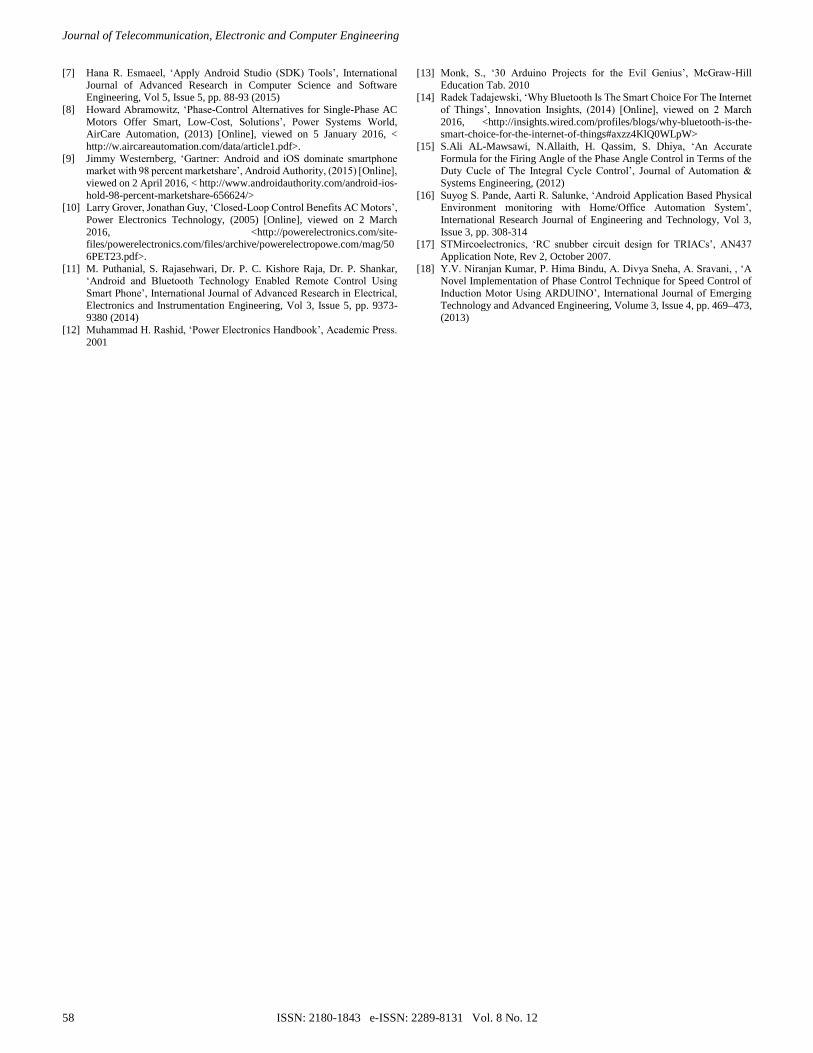
Figure 14: Illumination vs Load RMS Voltage
Figure 14 shows the graphs of illumination vs load rms
voltage using Arduino microcontroller and Promark dimmer.
The illumination-load rms voltage behavior for both cases are
almost the same which the illumination is increased as load rms
voltage went up.
VII. CONCLUSION
In short, the remote AC power control circuit by phase
control method is built successfully. The control circuit is fully
controllable by the Android app via Bluetooth connection. The
power of load could be controlled by TRIAC with controlling
the time delay of firing pulses from Arduino microcontroller.
Moreover, there is insignificant of differences between
practical case and ideal case. Compared with a dimmer, the
Arduino microcontroller could control the AC load in a wider
range of power controlling.
REFERENCES
[1] Ankita Gupta, Rajeev Thakur, Sachin Murarka, ‘An Efficient Approach
to Zero Crossing Detection Based On Opto-Coupler’, International Journal of Engineering Research and Applications, Vol 3, Issue 5, pp.
834-838 (2013)
[2] Banzi, M. and Shiloh, M., ‘Make - getting started with Arduino: The open source electronics Prototyping platform’, 2nd edn, United States:
Make:Books/O’Reilly. 2015
[3] Diy_bloke, ‘Arduino controlled light dimmer’, Instructable,
[Online],viewed on 2 January 2015,
<http://www.instructables.com/id/Arduino-controlled-light-dimmer-
The-circuit/?ALLSTEPS> [4] Deyson, ‘LED Control using Arduino Bluetooth and Android’,
Instructable, [Online], viewed on 2 November 2015,
<http://www.instructables.com/id/LED-Control-using-Arduino-Bluetooth-and-Android-Pa/?ALLSTEPS>.
[5] Guangzhou HC Information Technology Co. Ltd., ‘HC Serial Bluetooth
Products’, User Instruction Manual, [Online], viewed on 2 November 2015, < http://www.tec.reutlingen-university.de/uploads/media/
DatenblattHC -05_BT-Modul.pdf>.
[6] Haseman, C. and Grant, K., ‘Beginning Android programming: Develop and design.’ United States: Peachpit Press Publications. 2013
Journal of Telecommunication, Electronic and Computer Engineering
58 ISSN: 2180-1843 e-ISSN: 2289-8131 Vol. 8 No. 12
[7] Hana R. Esmaeel, ‘Apply Android Studio (SDK) Tools’, International
Journal of Advanced Research in Computer Science and Software Engineering, Vol 5, Issue 5, pp. 88-93 (2015)
[8] Howard Abramowitz, ‘Phase-Control Alternatives for Single-Phase AC
Motors Offer Smart, Low-Cost, Solutions’, Power Systems World, AirCare Automation, (2013) [Online], viewed on 5 January 2016, <
http://w.aircareautomation.com/data/article1.pdf>.
[9] Jimmy Westernberg, ‘Gartner: Android and iOS dominate smartphone market with 98 percent marketshare’, Android Authority, (2015) [Online],
viewed on 2 April 2016, < http://www.androidauthority.com/android-ios-
hold-98-percent-marketshare-656624/> [10] Larry Grover, Jonathan Guy, ‘Closed-Loop Control Benefits AC Motors’,
Power Electronics Technology, (2005) [Online], viewed on 2 March
2016, <http://powerelectronics.com/site-files/powerelectronics.com/files/archive/powerelectropowe.com/mag/50
6PET23.pdf>.
[11] M. Puthanial, S. Rajasehwari, Dr. P. C. Kishore Raja, Dr. P. Shankar, ‘Android and Bluetooth Technology Enabled Remote Control Using
Smart Phone’, International Journal of Advanced Research in Electrical,
Electronics and Instrumentation Engineering, Vol 3, Issue 5, pp. 9373-9380 (2014)
[12] Muhammad H. Rashid, ‘Power Electronics Handbook’, Academic Press.
2001
[13] Monk, S., ‘30 Arduino Projects for the Evil Genius’, McGraw-Hill
Education Tab. 2010 [14] Radek Tadajewski, ‘Why Bluetooth Is The Smart Choice For The Internet
of Things’, Innovation Insights, (2014) [Online], viewed on 2 March
2016, <http://insights.wired.com/profiles/blogs/why-bluetooth-is-the-smart-choice-for-the-internet-of-things#axzz4KlQ0WLpW>
[15] S.Ali AL-Mawsawi, N.Allaith, H. Qassim, S. Dhiya, ‘An Accurate
Formula for the Firing Angle of the Phase Angle Control in Terms of the Duty Cucle of The Integral Cycle Control’, Journal of Automation &
Systems Engineering, (2012)
[16] Suyog S. Pande, Aarti R. Salunke, ‘Android Application Based Physical Environment monitoring with Home/Office Automation System’,
International Research Journal of Engineering and Technology, Vol 3,
Issue 3, pp. 308-314 [17] STMircoelectronics, ‘RC snubber circuit design for TRIACs’, AN437
Application Note, Rev 2, October 2007.
[18] Y.V. Niranjan Kumar, P. Hima Bindu, A. Divya Sneha, A. Sravani, , ‘A Novel Implementation of Phase Control Technique for Speed Control of
Induction Motor Using ARDUINO’, International Journal of Emerging
Technology and Advanced Engineering, Volume 3, Issue 4, pp. 469–473, (2013)
Related Documents