^,r T'.. 'I X..ry DOE/RL-90-37 UC-600 Remedial Investigation Phase 2 Supplemental Work Plan for the Hanford Site 1100-EM-1 Operable Unit Environmental Engineering Group Date Published April 1991 United States ' Department of Energy tg^ P.O. Box 550 abs ^0)>>? Richland, Washington 99352 ^s ^^ N •/ ^^^rS2yZgr t'tiZ Approved for Public Release

Welcome message from author
This document is posted to help you gain knowledge. Please leave a comment to let me know what you think about it! Share it to your friends and learn new things together.
Transcript
^,r T'.. 'I X..ry
DOE/RL-90-37
UC-600
Remedial InvestigationPhase 2 SupplementalWork Plan for theHanford Site1100-EM-1 Operable UnitEnvironmental Engineering Group
Date Published
April 1991
United States' Department of Energy tg^
P.O. Box 550 abs ^0)>>?Richland, Washington 99352 ^s ^^
N •/
^^^rS2yZgrt'tiZ
Approved for Public Release
DOE/RL-90-37
EXECUTIVE SUMMARY
The 1100-EM-1 Phase II remedial investigation supplemental work plan details theefforts for final characterization of the 1100-EM-1 Operable Unit that will provide data to beused for the evaluation of remedial operations in the Phase III 1100.EM-1 feasibility study.This work plan conforms with current guidance for remedial investigation and feasibilitystudy activities under the Comprehensive Environmental Response, Compensation, andLiability Act (EPA 1988), and is consistent with the National Oil and Hazardous SubstancesPollution Contingency Plan.
The 1104EM-1 Operable Unit is one of four operable units within the 1100 Area ofthe Hanford Site, which was placed on the National Priorities List in July 1989. A Phase Iremedial investigation report for the 1100-EM-1 Operable Unit was completed in August1990, and a Phase I and II feasibility study report was submitted in December 1990.
The Phase I remedial investigation recommended that additional characterization ofthe 1100-EM-1 Operable Unit should focus on the following:
• 1100-1 (Battery Add Pit) - The Phase I remedial investigation ground-watersampling results indicated elevated gross-alpha and gross-beta radiation levelsin the vicinity of the building (1171 Building) adjacent to the pit. However,additional rounds of ground-water monitoring completed after the publicationof the Phase I Remedial Investigation Report have not confirmed the existenceof elevated levels of radioactivity.
• 1100-2 (Paint and Solvent Pit) - Tetrachloroethene was detected during thePhase I remedial investigation soil gas survey, and also in ground-watersamples from a nearby, cross-gradient monitoring well at low concentrations.
• 1100-4 (Antifreeze Tank Site) - The Phase I remedial investigation ground-- water sampling results indicated elevated gross-alpha and gross-beta radiation
levels in the vicinity of the 1171 Building. However, additional rounds ofground-water monitoring completed after the publication of the Phase IRemedial Investigation Report have not confirmed the existence of elevatedlevels of radioactivity.
UN-1100-6 (Discolored Soil Site) - Surface soils at UN-1100-6 are contaminatedwith bis(2-ethylhexyl)phthalate at levels that may pose a low risk to workersat the operable subunit. A removal action is being initiated to remove thebis(2-ethylhexyl)phthalate. The Phase I remedial investigation surface soilsampling also indicated the presence of low concentrations of 1,1,1-trichloroethane.
• Horn Rapids Landfill - Soil sampling during the Phase I remedialinvestigation detected elevated concentrations of polychlorinated biphenyls atlevels of concern that may pose a low risk to workers at the operable subunit.Ground water in the vicinity of the Horn Rapids Landfill also containselevated levels of nitrate, trichloroethene, and radioactivity that cannot be
DOFJRL-9a37
attributed to the Hom Rapids Landfill with Phase I remedial investigationdata.
• Ephemeral Pool - Elevated levels of polychlorinated biphenyls are present inthe surface soils of this parking lot runoff basin.
• South Pit - This potential disposal area was identified during the Phase Iremedial investigation from historic aerial photographs, and requirescharacterization for possible Hanford Site related use and contamination.
The Phase II remedial investigation work plan provides a staged process for finalcharacterization of the 1100-EM-1 Operable Unit This approach is utilized because it is costeffective, and because the Phase I remedial investigation did not indicate the existence ofany i*r+n+in ent and substantial endangerment to human health or the environment At thedirection of the Environmental Protection Agency (EPA), the Department of Energy (DOE)has accepted responsibility for the characterization of a contaminant plume from AdvancedNuclear Fuels Corporation (ANF); ANF is located up-gradient from the Horn RapidsLandfill.
As a result of EPA's expanded work scope, the schedule for completion of the Phase IIRI has been extended. A location-specific summary of the level of effort necessary toimplement the Phase II remedial investigation, and to provide a draft report toenvironmental regulatory agencies by September, 1993, is provided below based on thePhase II remedial investigation schedule assumptions and EPA-directed activities.Modification of the scope of work planned may occur as results of characterization effortsbecome available.
• Operable Unit Wide - Additional ground-water data collected during thePhase I remedial investigation will be evaluated and plotted; monitoring wellsinstalled during the Phase I remedial investigation will be sampled. An
^ ecological investigation will be conducted focusing on identification ofpotential ground-water receptors through a well inventory, and further
•^ compilation of data regarding land- and water-use plans for the operable unitvicinity.
1100-2 (Paint and Solvent Pit) - A single ground-water monitoring well will beinstalled immediately downgradient from 1100-2 to determine if a plume oftetrachloroethene is migrating from the Paint and Solvent Pit; two additionalwells may be needed to delineate any such contamination encountered.
• UN-1100-6 (Discolored Soil Site) - A soil gas survey consisting ofapproximately nine probe locations will be conducted.
Horn Rapids Landfill - A geophysical survey to detect the presence ofconcentrations of ten or more drums will be conducted; soil sampling will beconducted to delineate the extent of the polychlorinated biphenylcontamination; EPA-directed shallow borings will be placed in areas of knowndisturbances. Potential ground-water contamination in the landfill vicinity willbe characterized through installation of ground-water monitoring wells; asingle well will be installed for a pump test of the unconfined aquifer; and a
n
DOE/RL-9a37
soil gas survey requiring approximately 75 probe locations will be used topreliminarily delineate the ground-water trichloroethene plume. About 35permanent soil gas probes will be installed to monitor for releases ofcontainerized liquid hazardous wastes potentially buried in the landfill.
• Ephemeral Pool - Soil samples will be obtained to delineate the vertical andareal distribution of polychlorinated biphenyl contamination.
South Pit - The South Pit will be evaluated as a Hanford Site relatedcontaminan t source through an information survey, a geophysical survey, asurface radiation survey and a soil gas survey. Further soil and ground-waterinvestigation will depend on data obtained from the contaminant sourceinvestigation.
iii
DOFJRL-9437
This page intentionally left blank
r,
iv
DOE/RL-90-37
CONTENTS
1.0 Introduction ........................................................ 1-1
1.1 Purpose Of Work Plan . . . . . . . . . . . . . . . . . . . . . . . . . . . . . . . . . . . . . . . . . . . 1-1
1.2 Organization Of Work Plan . . . . . . . . . . . . . . . . . . . . . . . . . . . . . . . . . . . . . . . 1-2
2.0 Phase I RI Summary And Condusions . . . . . . . . . . . . . . . . . . . . . . . . . . . . . . . . . . . . 2-12.1 Physical Characteristics . . . . . . . . . . . . . . . . . . . . . . . . . . . . . . . . . . . . . . . . . . . 2-12.2 Nature And Extent Of Contamination . . . . . . . . . . . . . . . . . . . . . . . . . . . . . . . 2-5
2.2.1 Contaminant Sources . . . . . . . . . . . . . . . . . . . . . . . . . . . . . . . . . . . . . . 2-52.2.2 Air Contamination ........................................ 2-62.2.3 Soil Contamination ........................................ 2-62.2.4 Ground-Water Contamination . . . . . . . . . . . . . . . . . . . . . . . . . . . . . . . 2-7
2.3 Contaminant Fate And Transport . . . . . . . . . . . . . . . . . . . . . . . . . . . . . . . . . . . 2-8
2.4 Risks to Human Health And The Environment . . . . . . . . . . . . . . . . . . . . . . . . 2-8
2.4.1 Human Health Risks . . . . . . . . . . . . . . . . . . . . . . . . . . . . . . . . . . . . . . 2-9
2.4.2 Environmental Risks . . . . . . . . . . . . . . . . . . . . . . . . . . . . . . . . . . . . . . . 2-9
3.0 Work Plan Rationale ................................................. 3-13.1 Data Quality Objectives Process . . . . . . . . . . . . . . . . . . . . . . . . . . . . . . . . . . . . 3-1
3.1.1 Stage 1-Identification of Decision Types . . . . . . . . . . . . . . . . . . . . . . . 3-13.1.2 Stage 2-Identification of Data Uses and Needs . . . . . . . . . . . . . . . . . . 3-23.1.3 Stage 3-Design of Data Collection Program . . . . . . . . . . . . . . . . . . . . 3-3
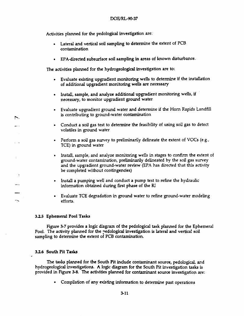
3.2 Work Plan Approach ......... ................................... 3-33.2.1 Operable-Unit-Wide Tasks . . . . . . . . . . . . . . . . . . . . . . . . . . . . . . . . . . 3-33.2.2 1100-2 Tasks ............................................. 3-63.2.3 UN-1100-6 Tasks . . . . . . . . . . . . . . . . . . . . . . . . . . . . . . . . . . . . . . . . . . 3-63.2.4 Horn Rapids Landfill Tasks . . . . . . . . . . . . . . . . . . . . . . . . . . . . . . . . . 3-63.2.5 Ephemeral Pool Tasks . . . . . . . . . . . . . . . . . . . . . . . . . . . . . . . . . . . . 3-113.2.6 South Pit Tasks . . . . . . . . . . . . . . . . . . . . . . . . . . . . . . . . . . . . . . . . . . 3-11
3.3 Data Evaluation Methodologies . . . . . . . . . . . . . . . . . . . . . . . . . . . . . . . . . . . 3-14
4.0 Phase II Remedial Investigation Tasks . . . . . . . . . . . . . . . . . . . . . . . . . . . . . . . . . . . . 4-14.1 Project Management Tasks . . . . . . . . . . . . . . . . . . . . . . . . . . . . . . . . . . . . . . . . 4-1
4.1.1 Task 1-General Management . . . . . . . . . . . . . . . . . . . . . . . . . . . . . . . 4-24.1.2 Task 2-Meetings . . . . . . . . . . . . . . . . . . . . . . . . . . . . . . . . . . . . . . . . . 4-24.1.3 Task 3-Cost Control . . . . . . . . . . . . . . . . . . . . . . . . . . . . . . . . . . . . . . 4-24.1.4 Task 4-Schedule Control . . . . . . . . . . . . . . . . . . . . . . . . . . . . . . . . . . . 4-24.1.5 Task 5-Data Management . . . . . . . . . . . . . . . . . . . . . . . . . . . . . . . . . . 4-24.1.6 Task 6--Quality Assurance . . . . . . . . . . . . . . . . . . . . . . . . . . . . . . . . . . 4-34.1.7 Task 7-Health and Safety . . . . . . . . . . . . . . . . . . . . . . . . . . . . . . . . . . 4-34.1.8 Task 8-Community Relations . . . . . . . . . . . . . . . . . . . . . . . . . . . . . . . 4-34.1.9 Task 9-Progress Reports . . . . . . . . . . . . . . . . . . . . . . . . . . . . . . . . . . . 4-3
4.2 Operable-Unit-Wide Tasks . . . . . . . . . . . . . . . . . . . . . . . . . . . . . . . . . . . . . . . . 4-34.2.1 Task 1-Hydrogeological Investigation for the 1100-EM-1 Operable Unit 4-44.2.2 Task 2-Ecological Investigation for the 1100-EM-1 Operable Unit .... 4-94.2.3 Task 3-Geodetic Control for the 1100-EM-1 Operable Unit ........ 4-10
4.3 1100-2 Tasks .. ................................................ 4-114.3.1 Task 1-Hydrogeological Investigation for 1100-2 . . . . . . . . . . . . . . . . 4-11
4.4 UN-1100-6 Tasks . . . . . . . . . . . . . . . . . . . . . . . . . . . . . . . . . . . . . . . . . . . . . . . 4-13
v
DOE/RL-90-37
CONTENTS(Continued)
4.4.1 Task 1-Contaminant Source Investigation for UN-1100-6 ......... 4-154.4.2 Task 2-Hydrogeological Investigation for UN-1100-6 . . . . . . . . . . . . 4-18
4.5 Horn Rapids Landfill Tasks . . . . . . . . . . . . . . . . . . . . . . . . . . . . . . . . . . . . . . 4-2245.1 Task 1-Contaminant Source Investigation for Horn Rapids Landfill . 4-2245.2 Task 2-Pedological Investigation for Hom Rapids Landfill ........ 4-234.5.3 Task 3-Hydrogeological Investigation for Horn Rapids Landfill .... 4-28
4.6 Ephemeral Pool Tasks ........................................... 4-394.6.1 Task 1-Pedological Investigation for Ephemeral Pool . . . . . . . . . . . . 4-39
4.7 South Pit Tasks ................................................ 4-404.7.1 Task 1-Contaminant Source Investigation for the South Pit ....... 4-404.7.2 Task 2-Pedological Investigation for the South Pit . . . . . . . . . . . . . . 4-444.7.3 Task 3-Hydrogeological Investigation for the South Pit .......... 4-47
4.8 Treatability Study Tasks . . . . . . . . . . . . . . . . . . . . . . . . . . . . . . . . . . . . . . . . . 4-474.8.1 Task 1-Treatability Investigation Work Plan Development ........ 4-484.8.2 Task 2-Treatability Investigation Implementation . . . . . . . . . . . . . . . 4-50
4.9 Data Evaluation Tasks . . . . . . . . . . . . . . . . . . . . . . . . . . . . . . . . . . . . . . . . . . 4-514.9.1 Task 1-Contaminant Source Data . . . . . . . . . . . . . . . . . . . . . . . . . . . 4-514.9.2 Task 2-Pedological Data . . . . . . . . . . . . . . . . . . . . . . . . . . . . . . . . . . 4-514.9.3 Task 3-Hydrogeologic Data . . . . . . . . . . . . . . . . . . . . . . . . . . . . . . . . 4-524.9.4 Task 4-Ecological Data . . . . . . . . . . . . . . . . . . . . . . . . . . . . . . . . . . . 4-52
4.10 Verification of Contaminant- And Location-Specific LegallyApplicable or Relevant And Appropriate EnvironmentalStandards, Requirements, Criteria, And Limitations Task . . . . . . . . . . . . . . 4-52
4.11 Baseline Risk Assessment Refinement Tasks . . . . . . . . . . . . . . . . . . . . . . . . . 4-534.11.1 Task 1-Contaminant Identification . . . . . . . . . . . . . . . . . . . . . . . . . 4-534.11.2 Task 2-Exposure Assessment Refinement . . . . . . . . . . . . . . . . . . . . 4-534.11.3 Task 3-Toxicity Assessment Refinement . . . . . . . . . . . . . . . . . . . . . 4-534.11.4 Task 4-Risk Characterization Refinement . . . . . . . . . . . . . . . . . . . . 4-54
4.12 Phase II Remedial Investigation Report Task . . . . . . . . . . . . . . . . . . . . . . . . 4-54
5.0 Schedule ........................................................... 5-1
6.0 References ......................................................... 6-1
Appendix A Quality Assurance Project Plan
vi
DOEIRL-90-37
FIGURES
2-1 1100-EM-1 Operable Unit . . . . . . . . . . . . . . . . . . . . . . . . . . . . . . . . . . . . . . . . . . . 2-2
3-1 Phase II RI Data Needs . . . . . . . . . . . . . . . . . . . . . . . . . . . . . . . . . . . . . . . . . . . . . 3-4
3-2 Operable-Unit-Wide Hydrogeological, and Ecological Investigationsand Geodetic Control .............................................. 3-5
73-3 1100-2 Operable Subunit Hydrogeological Investigation . . . . . . . . . . . . . . . . . . . . 3-3-4 UN-1100-6 Operable Subunit Contaminant Source. . . . . . . . . . . . . . . . . . . . . . . .
and Hydrogeological Investigations . . . . . . . . . . . . . . . . . . . . . . . . . . . . . . . . . . . 3-83-5 Horn Rapids Landfill Operable Subunit Contaminant Source and
Pedological Investigations . . . . . . . . . . . . . . . . . . . . . . . . . . . . . . . . . . . . . . . . . . . 3-93-6 Hom Rapids Landfill Operable Subunit Hydrogeological Investigation ........ 3-103-7 Ephemeral Pool Pedological Investigation . . . . . . . . . . . . . . . . . . . . . . . . . . . . . . . 3-123-8 South Pit Contaminant Source, Pedological, and Hydrogeological
Investigations .................................................... 3-134-1 Phase I RI Monitoring Well Locations . . . . . . . . . . . . . . . . . . . . . . . . . . . . . . . . . . 4-5/64-2 Proposed Location for the Stage 1 Phase II RI Monitoring Well
for the 1100-2 Operable Subunit . . . . . . . . . . . . . . . . . . . . . . . . . . . . . . . . . . . . . . 4-124-3 Operable-Unit-Specific Upgradient Ground-Water Monitoring Well Locations .. 4-144-4 Proposed Locations for the Phase II RI Soil Gas Probes for
the UN-1100-6 Operable Subunit . . . . . . . . . . . . . . . . . . . . . . . . . . . . . . . . . . . . . 4-164-5 Background Soil Sampling Locations for the 1100-EM-1 Operable
Unit ............................................................ 4-17
4-6 Proposed Area to Conduct the Surface Radiation Survey atUN-1100-6 Operable Subunit . . . . . . . . . . . . . . . . . . . . . . . . . . . . . . . . . . . . . . . . 4-19
4-7 Proposed Location of the Contingent Stage 1 Ground-WaterMonitoring Well at the UN-1100-6 Operable Subunit . . . . . . . . . . . . . . . . . . . . . . 4-21
4-8 Proposed Locations for 35 Permanent Soil Gas Probes at theHorn Rapids Landfill Operable Subunit . . . . . . . . . . . . . . . . . . . . . . . . . . . . . . 4-25/26
4-9 Proposed Stage 1 Soil Sampling for PCB Delineation at the HornRapids Landfill Operable Subunit . . . . . . . . . . . . . . . . . . . . . . . . . . . . . . . . . . . . . 4-27
4-10 Proposed Stage 1 Soil Boring Locations and Burial Trench Locationsat Horn Rapids Landfill Operable Subunit . . . . . . . . . . . . . . . . . . . . . . . . . . . . . . 4-29
4-11 Proposed Areas for Potential Upgradient Monitoring Well Locationsat the Hom Rapids Landfill Operable Subunit . . . . . . . . . . . . . . . . . . . . . . . . . . . 4-31
4-12 Proposed Transects for Preliminary Ground-Water Plume Delineationby Soil Gas Survey and Proposed Soil Gas Testing Locations at theHom Rapids Landfill Operable Subunit . . . . . . . . . . . . . . . . . . . . . . . . . . . . . . . . 4-34
4-13 Proposed Stage 1 Monitoring Well Locations at Horn Rapids Landfill OperableSubunit ........................................................ 4-36
4-14 Diagram of Extraction Well/Pump Construction at the Hom RapidsLandfill Aquifer Pump Test . . . . . . . . . . . . . . . . . . . . . . . . . . . . . . . . . . . . . . . . . . 4-38
4-15 Proposed Stage 1 Soil Sampling Locations at the Ephemeral Pool ............ 4-414-16 Proposed Area to Conduct the Surface Radiation Survey for the
South Pit ........................................................ 4-434-17 Proposed Transects for Geophysical Surveys at the South Pit . . . . . . . . . . . . . . . 4-45
vii
DOE/RL-90-37
FIGURES(Continued)
4-18 Proposed Soil Gas Probe Locations for the South Pit . . . . . . . . . . . . . . . . . . . . . . 4-465-1 Schedule for the 1100-EM-1 Operable Unit Phase II Remedial
Investigation and Feasibility Study . . . . . . . . . . . . . . . . . . . . . . . . . . . . . . . . . . . . 5-3/4
TABLES
41 1100-EM-1 Operable Unit Ground Water Sampling Schedule for 1991 ......... 4-84-2 Survey Data Types for Sampling Locations at the 1100.EM-1
Operable Unit . . . . . . . . . . . . . . . . . . . . . . . . . . . . . . . . . . . . . . . . . . . . . . . . . . . . 4-10
-,,
viii
DOEJRL-90-37
ACRONYMS
.3
r
amsl above mean sea levelANF Advanced Nuclear Fuels CorporationARARs legally aRRb cable or relevant and pQvrovriate. federal and state
environmental standards, Igouirements, criteria, and limitationsBEHP bis(2-ethylhexyl)phthalateCERCLA Comprehensive Environmental Response, Compensation, and Liability
ActCRP community relations planDOE United States Department of EnergyDOE-RL United States Department of Energy, Richland Operations OfficeDMP data management planDQO data quality objectivesEcology Washington State Department of EcologyEMI electromagnetic inductionEPA United States Environmental Protection AgencyFS feasibility studyFSP field sampling planGAI Golder Associates Inc.GPR ground penetrating radarHSP health and safety planHWOP hazardous waste operations permitMAG magnetometryNCP National Oil and Hazardous Substances Pollution Contingency PlanNPL National Priorities ListNS/EW north-south/east-westPCB polychlorinated biphenylPCE tetrachloroethenePMP project management planQAPP quality assurance project planQA/QC quality assurance/quality controlRCRA Resource Conservation and Recovery ActRl/FS remedial investigation/feasibility studySVOC semi-volatile organic compoundsTAL target analyte listTCA 1,1,1-trichloroethaneTCE trichloroetheneTCL target compound listTPA Tri-Party AgreementTSD treatment, storage, or disposalUSGS United States Geologic SurveyVOA volatile organic analysesVOC volatile organic compoundWAC Washington Administrative CodeWHC Westinghouse Hanford Company
ix

DOE/RL-90-37
This page intentionally left blank.
x
DOE/RL-90-37
1.0 IIVTRODUCTION
The 1100-EM-1 Operable Unit is one of four hazardous substance release project unitsassociated with the 1100 Area of the United States Department of Energy's (DOE's) HanfordSite. In July 1989, the United States Environmental Protection Agency (EPA) placed the1100 Area, and three other Hanford Site areas, on the National Priorities List (NPL)contained within Appendix B of the National Oil and Hazardous Substances PollutionContingency Plan (NCP, 40 CFR 300). (Note: All regulatory and statutory citations withinthis work plan refer to the version of the regulation or statute in effect, as amended, on thedate of work plan publication.) The EPA took this action pursuant to their authority underthe Comprehensive Environmental Response, Compensation, and Liability Act (CERCLA, 42USC 9601 et seq.).
In anticipation of this regulatory action, DOE Richland Operations (DOE-RL) dividedthe 1100 Area into four operable units and initiated CERCLA response planning for1100-EM-1-the operable unit assigned the highest priority, within both the 1100 Area andthe Hanford Site as a whole, by DOE-RL, EPA, and Washington State Department of
^ Ecology (Ecology).
The DOE-RL, EPA, and Ecology issued the Hanford Federal Facility Agreement andConsent Order, the Tri-Party Agreement (TPA, Ecology et al. 1990a), in May 1989. Thisagreement, among other things, governs all CERCLA efforts at the Hanford Site. In August1989, a remedial investigation/feasibility study (RI/FS) work plan for the 1100-EM-1 OperableUnit (DOE-RL 1989) was issued pursuant to the TPA. Upon publication of this work plan,DOE-RL initiated a full-scale effort on the first phase of the 1100-EM-1 RI. The Phase I RIreport was submitted to EPA and Ecology for review in August, 1990.
In February 1990, Westinghouse Hanford Company (Westinghouse Hanford or WHC,DOE-RL's Hanford Site operations contractor) issued Task G-90-32, under WestinghouseHanford Letter Order MDR-SW-666693, to Golder Associates Inc. (GAl). This task, andsubsequent tasks, authorized GAI to develop the Phase II RI supplemental work plancontained herein.
1.1 PURPOSE OF WORK PLAN
The purpose of the 1100-EM-1 Phase II RI is to gather and develop a sufficientamount of the necessary information required to complete the development and analysis ofoperable unit remedial alternatives during the FS. The remedial alternatives analysis will, inturn, be used by the TPA signatories to make a risk-management-based selection of aremedy for the releases of hazardous substances from the operable unit
In accordance with the TPA, the 1100-EM-1 RUFS is being conducted in a concurrent,interactively phased manner. The data collected and evaluated during Phase I RI activitiesprovided information for a preliminary analysis of remedial alternatives in the FS, and thePhase I RI findings and the preliminary FS analyses provided a focus for further RIactivities. The goal of the Phase II RI is to further, to the degree necessary to complete theFS, the understanding of the nature and extent of the threat to human health and theenvironment posed by releases of hazardous substances from the 1100-EM-I Operable Unit.
1-1
DOFJRL-9Q37
The purpose of this work plan is to document the Phase II RI tasks established to achieve
this goal.
1.2 ORGANIZATION OF WORK PLAN
The work plan for the 1100.EM-1 Operable Unit Phase II RI conforms with current
guidance for RUFS activities under CERCLA (EPA 1988), and is consistent with the NCP. It
has been completed with current knowledge of conditions at the operable unit, but may
require modifications as additional information becomes available and a better
understanding of operable unit conditions is attained.
The Phase II RI work plan provides a staged process for final characterization of the
1100-EM-1 Operable Unit This approach is utilized because it is cost effective, and because
the Phase I RI did not indicate the existence of any imminent and substantial endangerment
to human health or the environment
New characterization data and directed actions by EPA may require re-definition of
tasks in the work plan. Changes in the work will be agreed upon during unit managers
meetings and documented on change control forms.
Five chapters, in addition to this introduction, are included in this work plan.
Chapter 2 presents the Phase I RI summary and conclusions. It summarizes the existing
data, environmental setting, and contaminant transport and exposure pathways to develop
a conceptional model for the 1100-EM-1 Operable Unit Chapter 3 provides the rationale
and objectives for the Phase II RI activities. Chapter 4 presents the tasks necessary to
conduct the Phase II RI.
A project schedule is presented in Chapter 5. Modifications to the schedule may need
to be made as information is obtained during project implementation. Chapter 6 provides
references for literature cited in the work plan. There is one appendix to this work plan,
- Appendix A - Quality Assurance Project Plan (QAPP).
The elements of a field sampling plan (FSP) are provided throughout the work plan,
and as such, a separate FSP is not provided. A FSP normally consists of the following sixelements: site background, sampling objectives, sample location and frequency, sampledesignation, sampling equipment and procedures, and sample handling and analysis.Operable unit background is addressed in Chapter 2 of the work plan. Sampling objectivesand sample location and frequency information is provided within field task descriptions inChapter 4. Sample designation, sampling equipment and procedures, and sample handlingand analysis information is addressed in the QAPP by reference to the appropriateprocedure. Incorporating the FSP elements in the work plan eliminates redundancy andresults in a more compact plan of greater utility.
1-2
DOE/RL-90-37
2.0 PHASE I RI SUMMARY AND CONCLUSIONS
An RI, by its very nature, is a complex, multiple-objective phase of an importantregulatory process. It demands the use of a multi-disciplinary investigational approach todefine the nature and extent of any threats to human health and the environment posed byreleases of contaminants from a site, and any other information needed to support anevaluation of remedial alternatives during the FS phase of the project.
In this section, a summary of the findings of the initial phase of this process for the1100-EM-1 Operable Unit is presented. This summary is presented below in terms of thephysical characteristics (Section 2.1), the nature and extent of contamination (Section 2.2),the environmental fate and transport of operable unit contaminants (Section 2.3), and therisks posed to human health and the environment by the contaminants released from theoperable unit (Section 2.4). Detailed discussions on these topics are provided in the Phase IRI report (DOE-RL 1990).
i`.
2.1 PHYSICAL CHARACTERISTICS
The 1100 Area, the central warehousing, vehicle maintenance, and transportationoperations center for the Hanford Site, was designated an NPL site in July 1989. This NPLsite was divided into four operable units, and the first equipment maintenance operableunit, 1100-EM-1, was assigned the highest priority. A detailed presentation of the regionaland local aspects of the physical characteristics of the operable unit is in DOE-RL 1990. Thefollowing summary focuses on the major issues related to contaminant sources,meteorology, surface hydrology, geology, pedology, hydrogeology, and ecology.
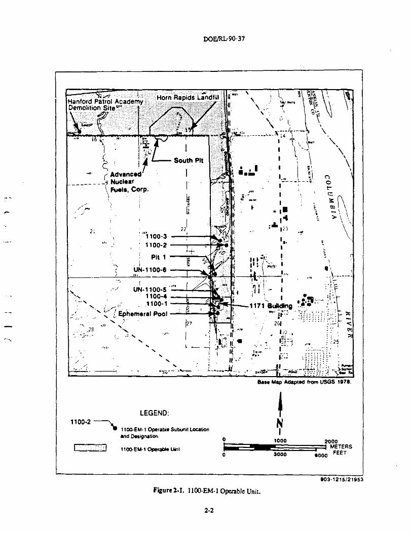
The 1100•EM-1 Phase I RI report (DOE-RL 1990) recommended further investigationat six waste management units assigned to or within the operable unit. Given their distinctgeographical separation from one another, these facilities, shown in Figure 2-1, are regardedas operable subunits, and are briefly described below:
^ • 1100-1 (Battery Acid Pit)-an unlined dry sump, or french drain, used for thedisposal of waste acid from vehide batteries
• 1100-2 (Paint and Solvent Pit)-a former sand and gravel pit subsequently usedfor the disposal of construction debris and, reportedly, waste paints, thinners,and solvents
• 1100-4 (Antifreeze Tank Site)-the site of a former underground storage tankused for the disposal of waste vehicle antifreeze
• UN-1100-6 (Discolored Soil Site)--the location of an apparent disposal eventonto the ground surface involving a container of organic waste liquids
• Horn Rapids Landfill-a solid waste facility used primarily for the disposal ofoffice and construction waste and the burning of classified documents;asbestos, sewage sludge, fly ash, and, potentially, drums of unidentifiedorganic liquids alleged to be disposed at this location
2-1
DOE/Rl: 90-37
Advanced^NuclNarFwIS. Corp.
^ zr21 22 ^i -' 123 .°i
1100-3 :, I
\ \
0
c
9 \ 1
1100-2 3 ^ n `
Pit 1I
r
1 •
t.t \- _
UN-1100-6-----
' 'UN-1100-5
q F
1100-41100-1 1171 BuNdfny
Ephemerel Pool.
^ ^7 r 261^
_7° \ tj ' •.'^ n:^ n ^ II -
:i25L
--4.:
dl-...... ._........ ,
Be" Mae Adanled Man USGS I
LEGEND:1100-z N
1100-EM-1 Operade Subunit Loutionand Designation
0 1000 2000^ ttME^I Operable Unt METERS
0 3000 6000FEET
oo3-1z1
Figure 2•1. 1100-EM-1 Operable Unit.
2-2
DOE/RL-90-37
• Ephemeral Pool-the location of 1100 Area parking lot runoff accumulation
during infrequent, high-intensity precipitation events.
Three waste management units and one miscellaneous location are not considered for
additional work during the Phase II RI (see Figure 2-1): 1100-3 Antifreeze and Degreaser
Pit, UN-1100-5 Radiation Contamination Incident, Hanford Patrol Academy Demolition Site,
and Pit 1. The 1100-3 operable subunit was considered to pose no significant contamination
problems after evaluation of Phase I data collection activities. The UN-1100-5 operable
subunit was considered to pose no significant contamination problem; no radioactivity was
found on the 1100 Area parking lot surface, and enough time has elapsed since the release
such that the radioisotopes involved are virtually completely decayed. For the purposes of
this report, the Hanford Patrol Academy Demolition Site was not regarded as part of the
1100-EM-1 Operable Unit. This waste management unit is a TSD (Treatment, Storage,
Disposal) facility that, if necessary, will be addressed separately under Ecology's Resource
Conservation and Recovery Act (RCRA) authority. Pit 1 was not considered to pose anysignificant contamination problem based on the evaluation of the samples collected during
the Phase I RI.
Since the publication of Draft A of this work plan, the 1100-1 Battery Acid Pit and
1100-4 Antifreeze Tank Site waste management units are now not considered for work
during the Phase II RI (see Figure 2-1). These two operable subunits were considered foradditional work at the condusion of the Phase I RI because the first round of ground-water
monitoring results indicated elevated gross-alpha and gross-beta radiation levels in thevicinity of the 1171 Building. Additional rounds of ground-water monitoring results have
not confirmed the first round results. Therefore, any additional work at 1100-1 and 11001Iis not necessary.
There are several other waste management facilities in the vicinity of the 1100-EM-1Operable Unit. These include two of the remaining three operable units that comprise the1100 Area NPL Site (the 1100-EM-2 and 1100-EM-3 Operable Units), a potato processingplant, a private nuclear fuel manufacturing facility, the Hanford Site nuclear fuel fabricationand research and development complex (the 300 Area), and the Richland Municipal Landfill.Historical aerial photographs (EPA 1990) indicate surface disturbances south of the HornRapids Landfill. This area of disturbance may have been used for waste disposal and isreferred to as the South Pit (see Figure 2-1).
The 1100-EM-1 Operable Unit is situated within an area possessing a relativelymoderate semiarid climate characterized by low precipitation, high evapotranspiration, andlight winds. No significant surface water bodies are located within or immediately adjacentto the operable unit, as the topography is relatively flat and the precipitation, combinedwith high evapotranspiration potential, provides little water to generate runoff; however,the Columbia River, an important regional surface water resource, is located approximately15 to 1.8 km (0.9 to 1.1 mi) to the east of the operable unit.
The operable unit is underlain by massive basalt flows that form the regional bedrock.The uppermost basalt flow in the area of the 1100-EM-1 Operable Unit is part of the IceHarbor Member of the Saddle Mountains Basalt Formation. Overlying the bedrock is theRingold Formation, an approximately 43- to 52-m (142- to 170-ft) thick deposit of mixedsediments of fluvial and lacustrine origin. The upper portion of this formation consists ofsandy gravels, gravelly sands, silty sandy gravels, and silty gravelly sands, with
2-3
DOE/RL-90-37
discontinuous sand lenses. Where penetrated by wells drilled for the Phase I RI, thesecoarse-grained sediments are underlain by finer-grained silts, clays, sandy silts, and sands.Based on published well logs, the Ringold Formation, at depths below those drilled for thePhase I RI, consists of silts, clays, gravels, gravelly sands, sands, and silty sands.
Above the Ringold Formation is the Hanford formation, the dominant facies of whichis the Pasco gravels, a variable mixture of boulders, cobbles, pebbles, sands, and silts ofglaaofluvial origin. Most of this formation, which is approximately 8- to 17-m (25- to 56-ft)thick at the operable unit, can be classified as unconsolidated basaltic sandy gravels togravelly sands and silty sandy gravels. Eolian deposits form a thin veneer (< 0.3-m to 6-m[1- to 20-ft] thick) over the Hanford formation in the area of the operable unit Thesedeposits consist of moderately-to-well-sorted, very-fine-to-medium-grained sands or siltysands that were originally derived from the Hanford formation.
The soils of the operable unit are primarily classified as regosols, and are largelydominated by the characteristics of the parent materials from which they are derived. Themoisture content of these soils ranges from 1 to 7%, and the soils contain only low amounts
c' of organic matter.
An unconfined aquifer, underlain by a silt aquitard, occurs below the operable unit.The aquitard, which was observed throughout the operable unit vicinity, separates theunconfined aquifer from lower confined to semi-confined aquifers. There is, however,uncertainty regarding the continuity of the aquitard, and potential exists for the aquitard tobe discontinuous. Regionally, the zone of recharge to the unconfined aquifer is located tothe west of the operable unit, and the aquifer discharges to the east, in the Columbia River.Local ground-water flow, as measured in early March and late May of 1990, is easterlybelow most of the operable unit, but northeasterly in the vicinity of the Horn RapidsLandfill. The easterly flow in the southern portion of the operable unit indicates thatground water passing beneath most of the operable subunits could pass through the City ofRichland well field, which is located between the operable unit and the Columbia River.
This well field supplements the dty's river-derived water supply during times of peakuse; however, essentially all water obtained from the field is river water derived from largeinfiltration ponds around which the withdrawal wells are sited. When in use, large-volumeinfiltration creates a mound that diverts the regional ground-water flow around the field.
With the exception of the 1100 Area, the entire Hanford Site within Benton County iszoned for restricted uses that are subject to federal government approval. Approximately45% of the Hanford Site is currently set aside as either wildlife or ecological reserves.
All land encompassing the 1100•EM-1 Operable Unit is currently zoned for eitherindustrial or restricted land use. Adjacent lands are zoned for industrial and commercialuse; however, agricultural use is currently being allowed in a heavy-manufacturing-usezone to the west of the operable unit and a medium-industrial-use zone to the east Thenearest agricultural-use zones are about 1.8 km (1.1 ad) to the west of the operable unit,and the dosest residential zone is approximately 0.8 km (0.5 mi) to the southeast of the1100-1 Battery Add Pit. County and city land-use plans and 1100 Area construction plansindicate that no significant changes in local land use are envisioned.
2-4
DOE/RL-9437
The Columbia River is the most significant surface-water body in the region. It servesas a source of drinking, industrial process, and irrigation water, and is used for variousrecreational activities. Ground water in the vicinity of the operable unit is used primarilyfor environmental monitoring, irrigation, and limited domestic use; all residential areas inthe vicinity have access to the city water supply. As mentioned earlier, ground waterderived from infiltrated river water is used to supplement the City of Richland water supplyduring times of peak seasonal demand.
No cultural resources, of either an archeological or historical significance, are locatedwithin the 1100-EM-1 Operable Unit
The operable unit is located in a shrub-steppe vegetational zone characterized by thepresence of a sagebrush/bunchgrass plant community in undisturbed areas and acheatgrasa/rabbitbrush/tumbleweed community in areas disturbed by human activities, suchas the operable unit. No endangered, threatened, or sensitive plant species or communitiesare known to inhabit the operable unit vicinity.
The most abundant fauna apparent in the region are the grasshopper, homed lark,western meadowlark, Great Basin pocket mouse, cottontail rabbit, jackrabbit, various raptorspecies, coyote, and mule deer. The primary animal species of interest that inhabit theoperable unit vicinity are the mule deer and two sensitive birds, the Swainson's hawk andthe long-billed curlew.
. No aquatic ecosystems are located on or adjacent to the operable unit; however, theColumbia River, while not supporting any endangered or threatened aquatic species, doessupport important populations of game fish, including various species of anadromoussalmonids.
2.2 NATURE AND EXTENT OF CONTAMINATION
The nature and extent of contamination at the 1100-EM-1 Operable Unit aresummarized below by the environmental media characterized during Phase I RI fieldactivities: contaminant sources, air, soil, and ground water. A detailed presentation of thenature and extent of operable unit contamination is found in the Phase I RI report(DOE-RL 1990).
2.2.1 Contaminant Sources
The six operable subunits of interest were evaluated in detail with respect to theirpotential as primary or secondary sources of significant environmental contamination at the1100-EM-1 Operable Unit These subunits are: the 1100.1 Battery Add Pit, the 1100-2 Paintand Solvent Pit, the 1100-4 Antifreeze Tank Site, the UN-1100-6 Discolored Soil Site, theHorn Rapids Landfill, and the Ephemeral PooL Each subunit is briefly described in Section2.1, above. Three other waste management units and a miscellaneous location, 1100-3,UN-1100-5, Hanford Patrol Academy Demolition Site, and Pit 1, respectively, are not givenfurther detailed consideration in the Phase II RI for reasons specified in Section 2.1.
2-5
DOE/RL-90-37
The original waste streams associated with each of the six operable subunits
considered in this plan are no longer in existence. Therefore, the soils of these subunits
are regarded as existing secondary sources of contamination. Soil contamination is
summarized in Section 2.2.3 below.
Surface radiation surveys were conducted at each of the operable subunits, with the
exception of LiN-1100-6 and the Ephemeral Pool; the results of all such surveys were
negative-no measurable radioactivity was encountered. Soil gas surveys were conducted at
the 1100-1, 1100-2, and Horn Rapids Landfill operable subunits. Tetrachloroethene (PCE)
was encountered within the soil gas of 1100-2 and the Horn Rapids Landfill, and
trichloroethene (TCE) and 1,1,1-trichloroethane (TCA) were also found at the landfill.
Of the other nearby waste management facilities mentioned in Section 2.1, one-the
Advanced Nuclear Fuels Corporation (ANF) complex-is known to have contributed
significant levels of contamination to operable unit ground waters in the vicinity of the
., , Horn Rapids Landfill. Contaminants known to have emanated from this facility are nitrate,
fluoride, sulfate, ammonia, and gross-alpha and gross-beta radiation.
^
2.2.2 Air Contamination
One round of ambient air monitoring data was available for operable unit
characterization; a second round of monitoring was conducted to assess potential
occupational impacts during RI activities. The quantity and quality of these data are such
that their utility is questionable; however, no indications of substantial deterioration of
ambient air quality in the vicinity of the operable unit were found under the wind
conditions present at the time the monitoring was conducted.
2.2.3 Soil Contamination
Soils were sampled at each operable subunit, and analyzed for Target Analyte List
` (TAL) and Target Compound List (TCL) parameters. In addition, samples obtained from the
1100-4 subunit were analyzed for ethylene glycol, and certain samples from the HornRapids Landfill were analyzed for asbestos fibers. Results were compared to operable-unit-specific background concentrations to determine the contaminants present, and preliminaryconservative toxicity screening was performed to determine contaminants of potentialconcern. Surface soils are conservatively considered to be those lying within 0.6 m (2 ft) ofthe ground surface. The findings for each subunit are summarized below:
• 1100-1 (Battery Acid Pit)-arsenic is the only contaminant of potential concern,encountered in the subsurface stratum in one sample at a concentration barelyexceeding background levels
1100-2 (Paint and Solvent Pit)-chromium is the only soil column contaminantof potential concern, encountered in a single surface sample at a concentrationnot greatly in excess of background. In fact, the mean surface chromiumconcentration at 1100-2 is lower than the mean background concentration;PCE was encountered during the soil gas survey conducted under the sourceinvestigation (see Section 2.2.1)
2-6
DOE/RL-90-37
• 1100-4 (Antifreeze Tank Site)-the surface stratum of the soil column was notsampled at this subunit, but a concrete floor prevents direct contact withsurface soils at this location; arsenic was found at elevated levels of potentialconcern, but only in a single sample obtained from below the water table
• UN-1100-6 (Discolored Soil Site)-only surface soils were sampled and analyzedat this subunit; the two contaminants of potential concern identified are bis(2rethylhexyl)phtha]ate (BEHP) and chlordane; BEHP is present in percentageconcentrations, and the distribution of the cldordane contamination is spatiallycorrelated with the BEHP contamination
• Hom Rapids Landfill-both surface and subsurface soils were sampled andanalyzed, but the subsurface sampling intentionally avoided areas of knownand suspected waste deposition; the soil column contaminants of potentialconcern are polychlorinated biphenyls (PCB), chromium, and arsenic. PCBwas detected at levels of potential concern at one subsurface and three surfacelocations; arsenic was encountered at levels of potential concern at one surfaceand two subsurface locations; chromium is more widely distributed, beingfound in 11 surface and eight subsurface locations at levels of potentialconcern; and TCE, PCE, and TCA were encountered in the gaseous phase ofthe landfill soils during the soil gas survey conducted for this subunit
• Ephemeral pool-two surface soil samples were obtained at this location; twocontaminants of potential concern, PCB and chlordane, areidentified-chlordane was found in both samples, and PCB in only one.
2.2.4 Ground-Water Contamination
Twenty-nine monitoring wells throughout the 1100-EM-1 Operable Unit vicinity, andtwo distribution lines from the nearby City of Richland well field, were sampled during thePhase I RI field activities. Twenty-one wells were sampled in the first round of monitoring,and 29 in the second round. The well field distribution lines were sampled in bothmonitoring rounds.
The samples obtained were analyzed for conventional, TAL, and TCL parameters.Results were compared to operable-unit- or Horn Rapids Landfffi-specific backgroundconcentrations, as appropriate, to determine the contaminants present. The determinationof landfill-specific background was necessary due to the presence of the reported,upgradient ANF plume. Preliminary conservative toxicity screening was performed todetermine contaminants of potential concern.
The only operable unit ground-water contaminant of potential concern identified,PCE, is present in a single well near the 1100-2 Paint and Solvent Pit; however, availabledata are currently insufficient to understand the magnitude and extent of thiscontamination.
Although existing data do not suggest operable unit sources, two other areas ofground-water contamination are present within the vicinity of the 1100-EM-1 OperableUnit. One is an area of generally deteriorated ground-water quality in the vicinity of the
2-7
DOE/RL-90-37
1171 Building that contains elevated concentrations of several contaminan t parameters,including gross-alpha radiation at levels that may be of interest. However, additionalrounds of ground-water monitoring completed after the publication of the Phase I RI Reporthave not confirmed the existence of elevated levels of radioactivity.
The other ground-water contaminants appear to form a plume that originatedupgradient from, and is passing beneath, the Horn Rapids LandfilL This plume ischaracterized primarily by the presence of high concentrations of TCE and nitrate, which,along with the operable unit contaminants of concern, are regarded as contaminants ofinterest
23 CONTAMINANT FATE AND TRANSPORT
The contaminant fate characteristics of nine contaminants of interest-arsenic, BEHP,chlordane, chromium, nitrate, PCB, PCE, TCA, and TCE--are discussed in the Phase I RIreport (DOE-RL 1990). These contaminants include the operable unit contaminants of
C_ potential concern and TCE and nitrate, the two ground-water contaminants thatcharacterize what appears to be a plume of upgradient origin with respect to the HornRapids Landfill. Potentially operative contaminant transport pathways for the operable unitare qualitatively identified and quantitatively evaluated, where feasible, in the Phase I RIreport (DOE-RL 1990).
The relevant, potentially operative contaminant transport pathways for the 1100-EM-1Operable Unit evaluated in the Phase I RI report were:
• Volatile emissions and atmospheric dispersion-PCE from 1100-2; TCE, PCE,and TCA from the Horn Rapids Landfill
- • Fugitive dust emissions and atmospheric dispersion-BEHP from UN-1100-6;arsenic, chromium, and PCB from the Horn Rapids Landfill
- • Direct contact of surface contamination-arsenic and chromium at 1100-3;BEHP and chlordane at UN-1100-6; arsenic, chromium, and PCB at the HornRapids Landfill; PCB and chlordane at the ephemeral pool
• Vadose-zone transport-considered to be insignificant
• Ground-water transport-TCE and nitrate in the vicinity of the Horn RapidsLandfill; available data are currently insufficient to evaluate PCEcontamination associated with 1100-2
• Surface-water transport-PCE, TCE, and nitrate in the Columbia River fromcontaminated ground-water discharge
• Terrestrial biological transport-arsenic, chromium, and PCB to humansthrough mule deer, and to Swainson's hawks and long-billed curlews, at theHorn Rapids Landfill
2-8
DOE/RL-9a37
• Aquatic biological transport-PCE, TCE, and nitrate uptake by fish in the
Columbia River.
2.4 RISKS TO HUMAN HEALTH AND THE ENVIRONMENT
Section 6 of the Phase I RI (DOE-RL 1990) provides a detailed assessment of the
baseline risks, under current land- and water-use conditions, posed to human health and
the environment by contaminant releases from and near the 1100-EM-1 Operable Unit
Brief summaries of the human and environmental portions of this assessment are
respectively provided in Sections 2.4.1 and 2.4.2 below.
2.4.1 Human Health Risks
Of the nine contaminants of interest at and near the 1100-EM-1 Operable Unit, nonealone, on the basis of an assessment of a hypothetically most exposed individual, wereshown to pose a significant threat to human health under current land- and water-use
r conditions. The overall risk associated with systemic toxicity is negligible and the overallrisk associated with carcinogenicity is approximately 2E-06. These cumulative risks includenot only all identified operable unit contaminants of potential concern, but also TCE andnitrate associated with a ground-water plume of apparent upgradient origin with respect tothe Horn Rapids Landfill.
Approximately 90% of the overall cancer risk to the most exposed individual wasattributed to two operable unit contaminants of concern, BEHP and PCB. The riskassessment indicated that the human population at risk for adverse effects of these twocontaminants consists of workers having direct access to and job duties on the UN-1100-6Discolored Soil Site, the Horn Rapids Landfill, and the Ephemeral Pool.
The BEHP poses a problem at the UN-1100-6 operable subunit, where it is present insurface soils in percentage concentrations. Ingestion and inhalation of these soils mayincrease cancer risks by about E-06. The Ephemeral Pool and the Horn Rapids Landfillhave surficial PCB soil contamination. The ingestion and inhalation of contaminated soilsat both facilities and the consumption of venison potentially contaminated by the landfillmay also increase cancer risks by about E-06.
Exposure to contaminated ground water downgradient of the 1100-2 operablesubunit, or in the vicinities of the 1171 Building and the Horn Rapids Landfill, althoughdismissed as an operative pathway under existing land- and water-use conditions, couldpose a human health hazard. Depending upon where a withdrawal well might be sitedand how it may be used, a significantly increased cancer risk could be associated with PCEand TCE ingestion and inhalation, and a systemic toxic hazard could be posed by theingestion of nitrate-contaminated ground water. Insufficient data exist to determinewhether ingestion of gross-alpha radiation could pose a significant risk
The PCE is associated with the 1100-2 Paint and Solvent Pit, and the TCE and nitrateare associated with a plume in the vicinity of the Horn Rapids Landfill; however, existingground-water data are not sufficient to prove the landfill, and thus the operable unit, to bethe source of the latter two contaminants. The gross-alpha radiation appears to be
2-9
DOE/RIr90-37
associated with the 1171 Building. However, additional rounds of ground-water monitoringcompleted after the publication of the Phase I RI Report have not confirmed the edstence ofelevated levels of radioactivity.
2.4.2 Environmental Risks
Two sensitive bird species known to inhabit the Hom Rapids Landfill vicinity, theSwainson's hawk and the long-billed curlew, were selected as indicator species for theterrestrial environmental evaluation. Arsenic, chromium, and PCB, due to their presence inlandfill surface soils, were the contaminants of potential concern for these species.
There is no evidence to support a conclusion of adverse contaminant impacts to theSwainson's hawks known to inhabit the landfill vicinity. A potential for such impacts,especially due to chromium, to the long-billed curlews that nest within and adjacent to thelandfill can not be ruled out; however, the evaluation presented for this sensitive terrestrialcommunity was simplistic and far from certain. The annual recurrence of both migratoryspecies suggests that they are successfully reproducing. Putting the operable unitcontamination problems into perspective, normal human activities (e.g., clearing,construction, facility operations, pesticide application, and off-road vehicle use) probablypose the greater threat to both species and most other terrestrial organisms.
An environmental evaluation was also performed for the aquatic community of theColumbia River. Tetrachloroethene, derived from the discharge of 1100-2 vicinity groundwaters to the river, was the contaminant of potential concern for this community. TCE andnitrate, derived from the discharge of Horn Rapids Landfill vicinity ground waters to theriver, are additional contaminants of interest.
As nitrate is a readily assimilated essential nutrient for aquatic plants, and the levelsthat could be contributed to the river are insignificant, it should pose no risk to aquatic life.The comparison of a conservatively biased prediction of TCE concentrations in the
- Columbia River indicated, with a fair degree of certainty, that no adverse impacts to aquaticcommunities will occur. Operable unit characterization data are currently insufficient toallow for a quantitative evaluation of potential PCE impacts, but by analogy, it is unlikelythat any adverse impact to aquatic life will occur.
2-10
DOE/RL-90-37
3.0 WORK PLAN RATIONALE
The Phase I RI report (DOE-RL 1990) provides a focused conceptual understanding of
the 1100-EM-1 Operable Unit Based on such an understanding, and on data needs for the
FS, the report concludes with recommendations for further RI activities. Theserecommendations have been refined to develop the work scope for the Phase II RI.
In accordance with the TPA, the Phase II RI work scope was developed consistent
with EPA's data quality objectives (DQO) process (EPA 1987a and 1987b) and McCain andJohnson (1990). This process is briefly described in Section 3.1, and the approach toconducting the Phase II RI for the 1100-EM-1 Operable Unit is outlined in a series of logicdiagrams in Section 3.2.
3.1 DATA QUALITY OBJECTIVES PROCESS
The work scope for the 1100-EM-1 Operable Unit Phase II RI was developedr consistent with EPA's DQO development process (EPA 1987a) and McCain and Johnson
(1990). The EPA (19876) explicitly states that they do not require specific DQO deliverables
during the remedial response process. The manner in which the three-stage DQO process
was used is briefly outlined below to provide an understanding of the logic behind the
development of this work plan. The three stages are decision types identification (Section
3.1.1), data uses and needs identification (Section 3.1.2), and data collection program design
(Section 3.1.3).
3.1.1 Stage 1-Identification of Decision Types
The first stage of the DQO process is the identification of decision types. There arefour steps within this stage: (1) the identification and involvement of data users; (2) theevaluation of available data; (3) the development of an operable unit conceptual model; and(4) the specification of project objectives and decisions.
Identification and involvement of data users has been arranged on a programmaticbasis for all Hanford Site environmental restoration activities through the TPA andassociated program plans. On the project level, primary data users maintain doseinvolvement in the DQO process through the opportunity to review and comment onproject plans and reports.
The Phase I RI report for 1100-EM-1 provides a thorough interim evaluation ofavailable data and presents these data in such a manner as to provide for a conceptualunderstanding of the operable unit The final activity of the Stage I DQO process, thespecification of project objectives and decisions for the Phase II RI, is documented by meansof logic diagrams and brief objectives statements in Section 3.2 (Work Plan Approach);further details are provided in Chapter 4.0 (Phase II RI Tasks).
3-1
DOF/RL-90-37
3.1.2 Stage 2-4dentification of Data Uses and Needs
The second stage of the DQO process consists of the identification of data uses andneeds. This stage can be viewed as occurring in six steps: (1) the identification of datauses; (2) the identification of data types; (3) the identification of data quality needs; (4) theidentification of data quantity needs; (5) the evaluation of sampling and analysis options;and (6) the review of precision, accuracy, representativeness, completeness, andcomparability (PARCC) parameters.
Each Phase II RI task and its component activities were developed to provide data fora specific project use. Concise objectives statements are provided within this work plan todocument the justification for each task and activity. Objectives statements in Section 3.2are general in nature, while those presented on a task- or activity-specific basis in Chapter4.0 are more focused. Objectives statements are also referenced in the accompanying QAPP(Appendix A).
The identification of data types required in the Phase II RI evolved from the^- identification of project-specific data gaps upon review of the Phase I RI report (DOE-RL
1990). The scope of work presented in this plan was specifically developed to eliminate, tothe extent practicable, such identified data gaps to a degree sufficient to allow thecompletion of the ongoing FS.
Data quality needs were identified upon consideration of integrated factors such asprioritized data uses, appropriate analytical levels, contaminants of concern (and those ofpotential concern or interest), contaminant levels of concern, analytical detection limits, andcritical sample locations. The Phase H RI approach laid out in Section 3.2, and the requiredtasks presented and described in Chapter 4.0 and scheduled in Chapter 5.0, are organizedsuch that data will be collected in an efficient and cost-effective manner that will provideinformation for high priority overall project needs. Analytical methods and investigationaltechniques were selected within appropriate analytical levels (e.g., screening methodologiesversus standard methodologies), in accordance with EPA (1987a) and McCain and Johnson(1990), to help maximize the efficiency and cost effectiveness of the Phase II RI. The secondphase of the operable unit investigation was designed to focus on those contaminants ofeither concern, potential concern, or interest that were identified in the Phase I RI report(DOE-RL 1990). On the basis of the baseline risk assessment and the contaminant levels ofconcern presented in the Phase I RI report, analytical methodologies were selected, to theextent technically feasible, to provide detection limits low enough to allow for usefulrefinement of risk evaluations. Finally, Chapter 4.0 sets forth means to provide for thecharacterization of critical locations and operable unit conditions (e.g., to define the extentof significant environmental contamination attributable to 1100-EM-1, and to better definebackground conditions).
Due to uncertainties in regard to the extent of contamination in variousenvironmental media, it is impossible to identify data quantity needs exactly. This problemis addressed by means of a staged approach to the Phase II RI. Data will be collected,analyzed, and evaluated in stages so that all involved parties can participate in decidingwhen the extent of contamination is well enough defined to allow FS completion.
Sampling and analysis options were evaluated in accordance with McCain andJohnson (1990). Selections were made on the basis of the data quality needs outlined above,
3-2
DOF/RL-90-37
and the applicability of relevant PARCC parameters, which are documented in the QAPP(see Appendix A).
3.13 Stage 3-Design of Data Collection Program
The third and final stage of the DQO process consists of the design of a datacollection program. Chapter 4.0 of this work plan presents such a data collection programin detail. The associated QAPP in Appendix A, and other Hanford Site program and 1100-EM-1 project plans incorporated into this plan by reference, provide the mechanism bywhich the data collection program for the second phase of the 1100-EM-1 RI will beimplemented, controlled, and documented.
3.2 WORK PLAN APPROACH
To provide information necessary to complete the FS, the Phase II RI will indude thefollowing integrated, subcomponent data collection tasks:
r
• Contaminant source investigation• Pedological investigation• Hydrogeological investigation• Ecological investigation• Geodetic control.
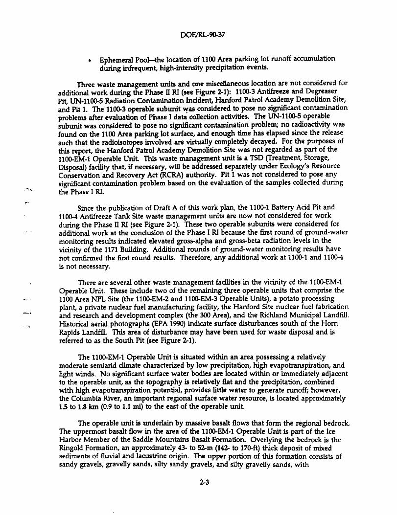
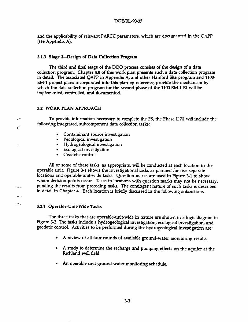
All or some of these tasks, as appropriate, will be conducted at each location in theoperable unit. Figure 3-1 shows the investigational tasks as planned for five separatelocations and operable-unit-wide tasks. Question marks are used in Figure 3-1 to showwhere decision points occur. Tasks in locations with question marks may not be necessary,pending the results from preceding tasks. The contingent nature of such tasks is describedin detail in Chapter 4. Each location is briefly discussed in the following subsections.
32.1 Operable-Unit-Wide Tasks
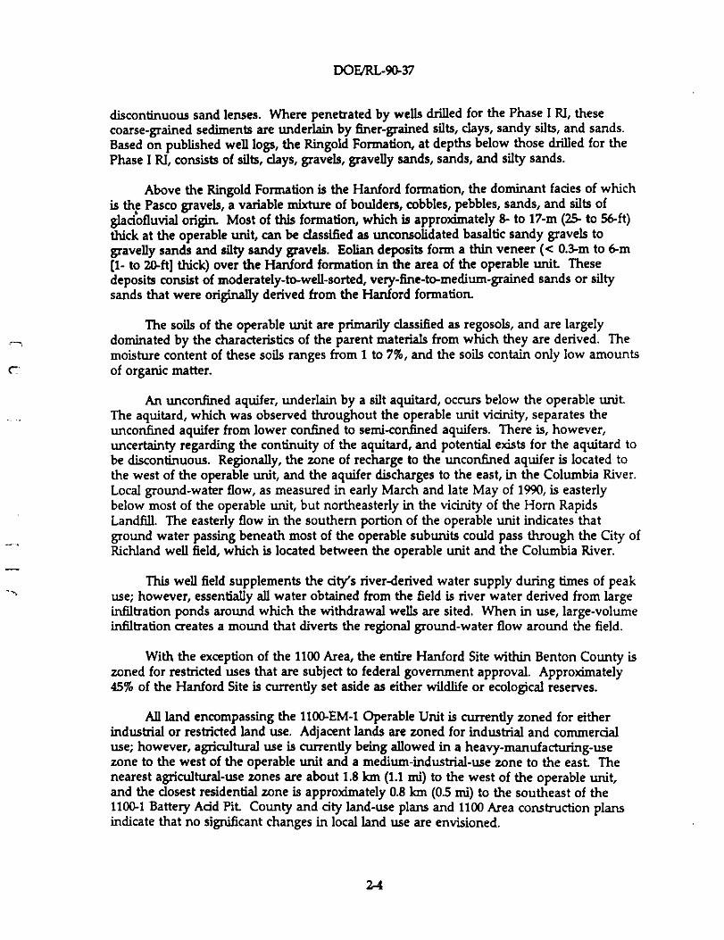
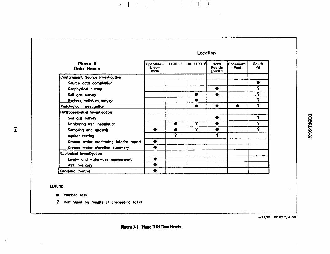
The three tasks that are operable-unit-wide in nature are shown in a logic diagram inFigure 3-2. The tasks include a hydrogeological investigation, ecological investigation, andgeodetic control. Activities to be performed during the hydrogeological investigation are:
• A review of all four rounds of available ground-water monitoring results
• A study to determine the recharge and pumping effects on the aquifer at theRichland well field
• An operable unit ground-water monitoring schedule.
3-3
^
Location
Phase 11
Data NeedsOperable-
Unit-Wide
1100-2 UN-1100- HomRapidsLandfill
EphemeralPool
SouthPit
Contaminant Source Investigation
Source data compilation •
Geophysical survey • ?
Soil gas survey • • . ?
Surface radiation survey ?
Pedological Investigation • • • ?
Hydrogeological Investigation
Soil gas survey • ?
Monitoring well Installation • ? • ?
Sampling and analysis • • ? • ?
Aquifer testing ? ?
Ground-water monitoring interim report •
Ground-water elevation summary •
Ecological Investigation
Land- and water-use assessment •
Well Inventory •
Geodetic Control •
LEGEND:
• Planned task
? Contingent on results of proceeding tasks
4/24/21 9031215\ 33eeE
J
11'igore 3-1. Phase Q Rl Data Needt.
W
U
HYDROGEOLOGICAL ECOLOGICAL1NVESMAn4N INVESTIGATION
GEODETICCQNTRQl
Prepore ground-water Assess future land- Refine Conduct geodeticmonitoring Interim report and water-use plans well inventory survey at all
11
sampling locations
Prepare ground-walerelevation summary
Conduct operable-unit-wide ground-water
monkoring
Phase II RIReport
9031275\ 338e5
^
^WJ
ftne 9-2. ope,.nh-unit-Wlde rx arogeolopcal. and Fiobgiplm.eu;guiom and Geodetic controL
DOFJRL-90-37
Activities to be performed during the ecological investigation are:
A land- and water-use assessment to compile and refine projections for1100-EM-1 Operable Unit vicinity
• A well inventory to refine the information gathered during the Phase I RI.
Geodetic control will be performed at all sampling points established for the Phase IIRI to document locational data.
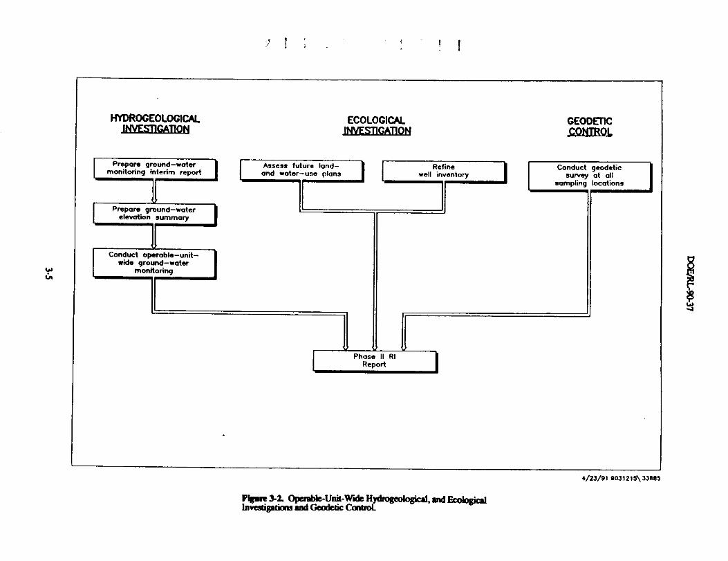
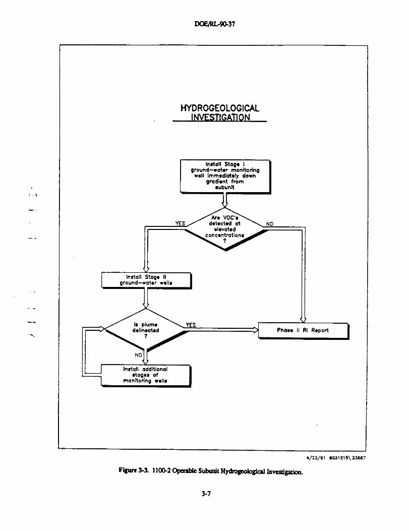
3.2.2 1100-2 Tasks
The one task planned for the 1100-2 Paint and Solvent Pit is shown in a logic diagramin Figure 3-3. The activities planned for this task are a staged monitoring well installation,sampling, and analysis to delineate the ground-water contamination attributable to the
^ 1100-2 operable subunit.
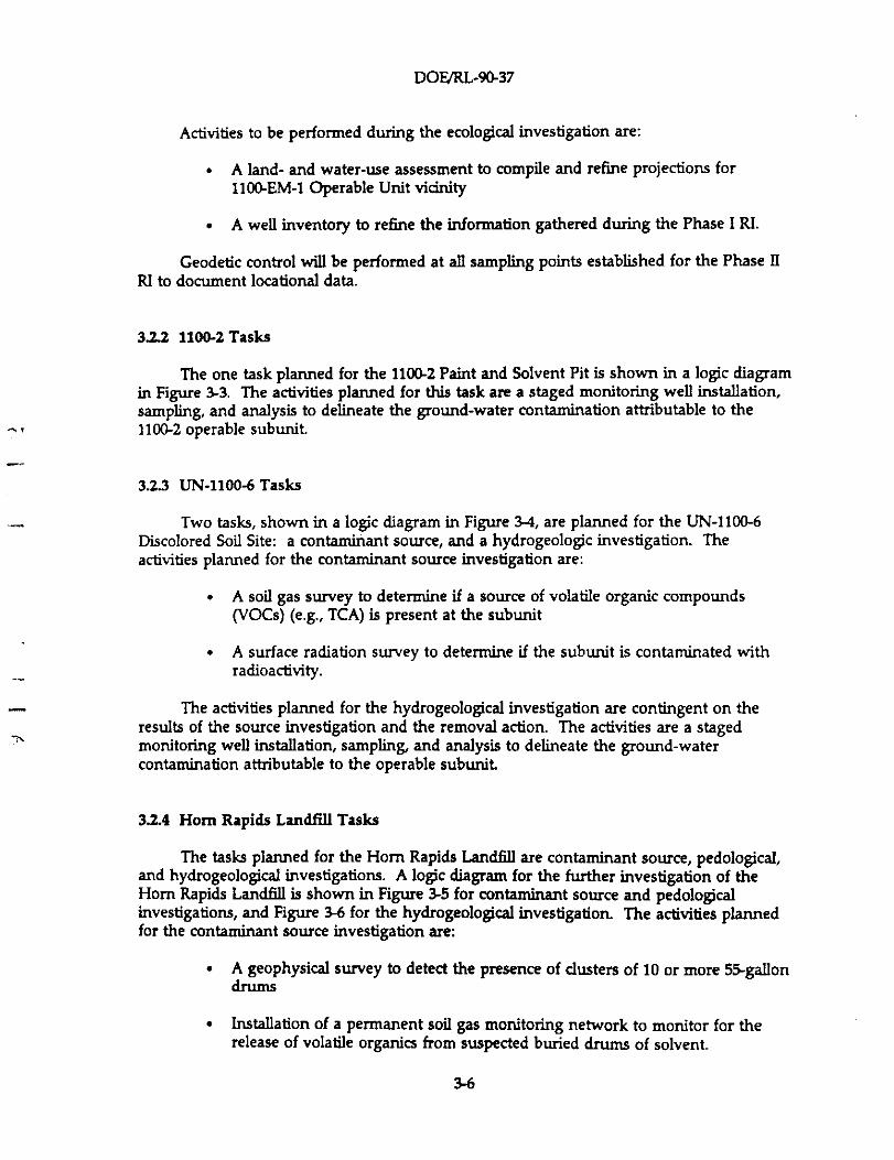
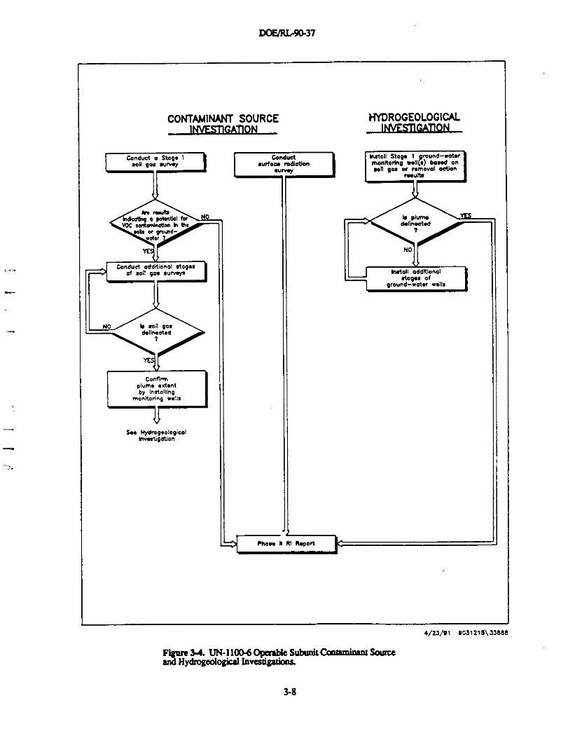
3.2.3 UN-1100-6 Tasks
Two tasks, shown in a logic diagram in Figure 3-4, are planned for the UN-1100-6Discolored Soil Site: a contaminant source, and a hydrogeologic investigation. Theactivities planned for the contaminant source investigation are:
• A soil gas survey to determine if a source of volatile organic compounds(VOCs) (e.g., TCA) is present at the subunit
• A surface radiation survey to determine if the subunit is contaminated withradioactivity.
-- The activities planned for the hydrogeological investigation are contingent on theresults of the source investigation and the removal action. The activities are a stagedmonitoring well installation, sampling, and analysis to delineate the ground-watercontamination attributable to the operable subunit
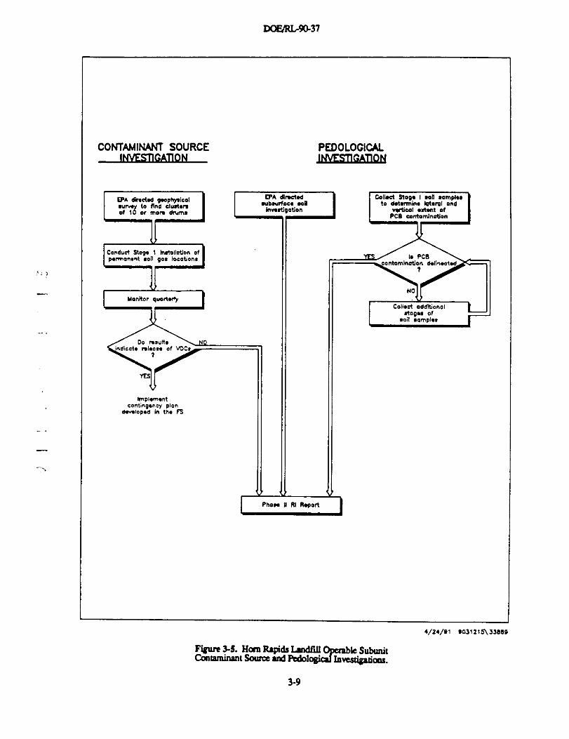
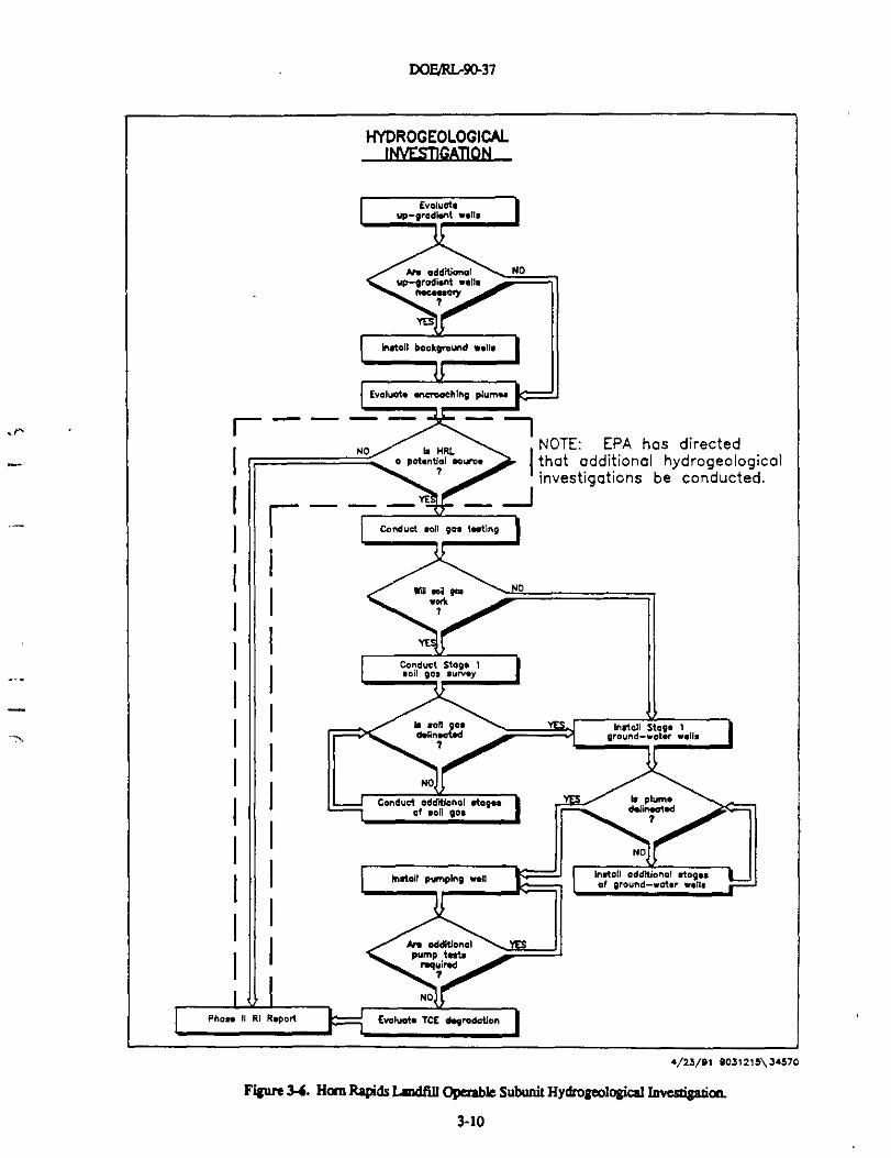
3.2.4 Horn Rapids Landfill Tasks
The tasks planned for the Horn Rapids Landfill are contaminant source, pedological,and hydrogeological investigations. A logic diagram for the further investigation of theHorn Rapids Landfill is shown in Figure 3-5 for contaminant source and pedologicalinvestigations, and Figure 3-6 for the hydrogeological investigation. The activities plannedfor the contaminant source investigation are:
• A geophysical survey to detect the presence of clusters of 10 or more 55-gallondn,ims
• Installation of a permanent soil gas monitoring network to monitor for therelease of volatile organics from suspected buried drums of solvent.
3-6
DOFJRIr9Q37
HYDROGEOLOGICALINVESTIGATION
,l
4/23/91 903121 S\ 33Da7
Figure 3-]. 1100.2 operawe Subunit Hymo®eological Invesigadon.
3-7
DOF/RLr9Q37
CONTAMINANT SOURCE MYDROGEOIOGICALINVESIIGATION INVESI1GATiON
4/23/9l 0031215\73eee
Figme 34. UN• 1100-6 OpQable Subunit Cmtaminsot Sam'.eand HyBrogeologsal Invesngatnos
3-8
DOP/RL.9437
CONTAMINANT SOURCE PEDOLOGICALINVESTIGA110N INVESI1GAT10N
I EPA AM.cI.A q.ophysical ^A ^n^^ Coll.d Stoq. I ron .on
.urv.y to nna dust.n .oe.orface eon to A.t.rmins lat.nl
of 10 er mon Arum. Nwrtiqotion •.rtieol .rt.nt ofPC8 contamination
Conduct Steg. 1 InrtallaUon ofp.mronsnl .oil qo, bcatlons ^ 4 PCB
^: n
I MonMor ouoA.ny INO
Do /.eYMs
nLaN of
bnpl.m.ntcontlnq.nry plen
e.rNOp.a in tM FS
I Pno.. n fq R.port I
Con.ct a0?Nonal.tnya of '
.oil /amal..
9031216\338e9
C^untHSomre andpbdo^Operabk Subunit
oglia1 Investigadpas.
3-9
DOF/RLr90-37
HYpROGEOLOGICALINVESTIGATION
.rr -- - - -
NO• oC
^ - -=
NOTE: EPA has directed^• that additional hydrogeological
investigations be conducted.
4/23/91 9031216\34570
Figare 3i. Ham Rapid¢ Laodfill Opcable Subunit HydroSeological Invesfipfioa
3-10
DOE/RL-90-37
Activities planned for the pedological investigation are:
Lateral and vertical soil sampling to determine the extent of PCBcontamination
• EPA-directed subsurface soil sampling in areas of known disturbance.
The activities planned for the hydrogeological investigation are to:
• Evaluate existing upgradient monitoring wells to determine if the installationof additional upgradient monitoring wells are necessary
• Install, sample, and analyze additional upgradient monitoring wells, ifnecessary, to monitor upgradient ground water
• Evaluate upgradient ground water and determine if the Horn Rapids Landfill^ is contributing to ground-water contamination
• Conduct a soil gas test to determine the feasibility of using soil gas to detectvolatiles in ground water
• Perform a soil gas survey to preliminarily delineate the extent of VOCs (e.g.,TCE) in ground water
• Install, sample, and analyze monitoring wells in stages to confirm the extent of
ground-water contamination, preliminarily delineated by the soil gas survey
and the upgradient ground-water review (EPA has directed that this activity
be completed without contingencies)
• Install a pumping well and conduct a pump test to refine the hydraulic" information obtained during first phase of the RI
^ • Evaluate TCE degradation in ground water to refine ground-water modelingefforts.
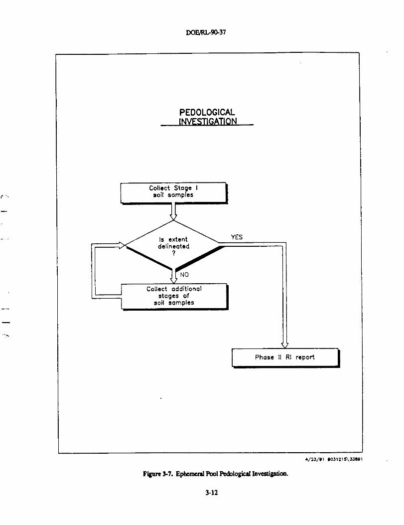
3.2.5 Ephemeral Pool Tasks
Figure 3-7 provides a logic diagram of the pedological task planned for the EphemeralPool. The activity planned for the ;+edological investigation is lateral and vertical soilsampling to determine the extent of PCB contamination.
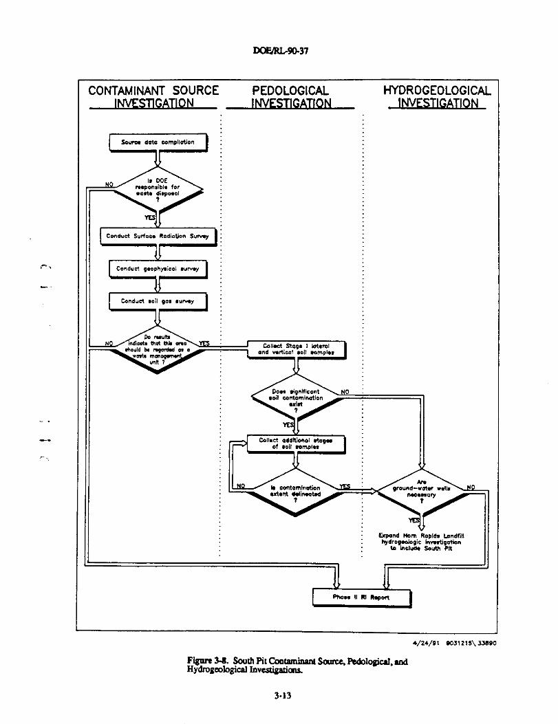
3.2.6 South Pit Tasks
The tasks planned for the South Pit indude contaminant source, pedological, andhydrogeological investigations. A logic diagram for the South Pit investigation tasks isprovided in Figure 3-8. The activities planned for contaminant source investigation are:
• Compilation of any existing information to determine past operations
3-11
DOF/R1.90-37
PEDOLOGICALINVESTIGATION
Collect Stage Isoil samples
Is extent YES
delineated
NO
Collect additionalstages of
soil samples
Phase II RI report
4/23/91 9031216\33891
Fignre 3-7. Ephemeisl Pool Pedological Investigatian.
3-12
DOFJRL9fF37
CONTAMINANT SOURCE PEDOLOGICALINVESTIGATION INVESTIGATION
Scuns data compilation
Is DOE -nsponsible forr.cria ditpa*ol
I Conduct SuAoou Radiation Surwy '
C. Conduct q*opnpieol aunq
Cnnduci *oil po, aunny
Do rwlbIs that Mb Lollrrct Sta9a I lateral
and wrlical wIt wmplh
Doa, tipnRicnntaoit wntomination
"rt4 -.00
01
Is contaminationutant dalinrrahd
HYDROGEOLOGICALINVESTIGATION
/ M \praund-raNr vrdh
naconcry\ t I
Expand Ibm Raplds LandfillIrydroqaebqic InvMiqetion
to inatuM South Pit
I PhoM 11 RI Raport I
♦/24/91 903121 S\ 37l90
Figure 3-8. South Pit Coataminant Source, Pedological, andHydrogeological Investigadang.
3-13
DOE/RL-90-37
• If the South Pit is determined to be a DOE responsibility, perform geophysical,
surface radiation, and soil gas surveys to determine the boundaries of
disturbed ground and potentially contaminated areas.
Activities planned for the pedological investigational task indude:
• If the results of the contaminat source investigation indicate a potential for soil
contamination, sampling and analysis of surface and subsurface soils will be
conducted.
The need for the implementation of the hydrogeologic task is contingent on the
contaminant source and pedological investigations. If further hydrogeological investigation
is required, the Horn Rapids Landfill hydrogeological investigation task will be expanded to
include the South Pit because of its dose proximity.
,...33 DATA EVALUATION METHODOLOGIES
During the Phase II RI, data will be evaluated as soon as they are validated and
available. This will allow the data to be used in rescoping and focusing the Phase II RI, as
appropriate. The data evaluation tasks will provide summaries and interpretations of the
collected information that will be used to verify contaminant- and location-specific legally
applicable or relevant and appropriate environmental standards, requirements, criteria, and
limitations (ARARs) to refine the baseline risk assessment, to continue and focus the FS, and
to complete the Phase II RI report.
Contaminant data for each environmental medium will be plotted to facilitate theunderstanding of the extent of contamination. Statistical comparisons with background
conditions will be performed to determine which contaminants attributable to the operable
unit are present in elevated concentrations. Although empirical observation will provide
_ the basis for estimating contaminant transport through the environmental media, the
computer model PORFLOW (Runchal and Sager 1990) is available at the Hanford Site for
the analysis of ground-water transport.
Once the list of contaminants of concern for the operable unit is confirmed or refined,
the task to refine the baseline risk assessment will be conducted. This task includes the
activities of refining contaminant identification, exposure assessment, toxicity assessment,
and risk characterization.
The ongoing development, screening, and analysis of remedial alternatives in the FSwill be performed using RI data in conjunction with standard costing and technicalprocedures, knowledge of prior technical applications, and engineering judgement.Technical and operable unit data will be evaluated to determine if a treatability investigationis required to evaluate a specific remedial action technology.
3-14
DOE/RL-90-37
4.0 PHASE II REMEDIAL INVESTIGATION TASKS
The purpose of this chapter is to set forth the various tasks to be implemented duringthe course of the additional operable unit characterization phase of the 1100-EM-1 RUFSproject. If treatability studies are necessary, a separate treatability investigation work planwill be developed.
The additional operable unit characterization tasks specified below are designed toprovide information to satisfy the work plan approach outlined in Chapter 3. Detailed FSPinformation on task and activity objectives and sample locations and frequencies is providedwith the task descriptions. Further FSP information on sample designations, samplingequipment and procedures, and sample handling and analysis procedures is addressed inthe QAPP (see Appendix A) by reference to the appropriate procedure.
This document is intended to be the final characterization plan for the 1100-EM-1Operable Unit. It will therefore be necessary to modify the plan during the course of thePhase II RI through established change control procedures (see Appendix A, Section 1.3).
^- Depending on the results of certain tasks, others may need to be created, supplemented, ordeleted. Necessary modifications will be agreed upon by DOE-RL, EPA, and Ecology at themonthly unit managers' meetings, and documented in meeting minutes; minutes will bedistributed to affected project personnel.
This chapter is divided into the following sections:
• Section 4.1 Project Management Tasks• Section 4.2 Operable-Unit-Wide Tasks• Section 4.3 1100-2 Tasks• Section 4.4 UN-1100-6 Tasks• Section 4.5 Horn Rapids Landfill Tasks• Section 4.6 Ephemeral Pool Tasks• Section 4.7 South Pit Tasks• Section 4.8 Treatability Study Tasks• Section 4.9 Data Evaluation Tasks• Section 4.10 Verification of Contaminant- and Location-Specific ARARs Task• Section 4.11 Baseline Risk Assessment Refinement Tasks• Section 4.12 Phase II Remedial Investigation Report Task
4.1 PROJECT MANAGEMENT 1ASKS
Project management is needed throughout the course of the Phase II RI to direct anddocument project activities and to secure the data and evaluations generated. Theadministrative and institutional tasks necessary to support overall project activities can befound in the project management plan (PMP) provided in the RUFS work plan for the1100-EM-1 Operable Unit (DOE-RL 1989). Specific project management tasks needed toimplement the additional operable unit characterization in the Phase D RI are:
• Task 1-General Management• Task 2-Meetings
4-1
DOE/RL-90-37
• Task 3-Cost Control• Task 4-Schedule Control• Task 5-Data Management• Task 6-Quality Assurance• Task 7-Health and Safety• Task 8-Community Relations• Task 9-Progress Reports
Each of these tasks is described in further detail below.
4.1.1 Task 1-General Management
The day-to-day supervision of, and communication with, project staff and
subcontractors is the object of this task Throughout the project, daily communications
between office and field personnel are required, along with periodic communications with
subcontractors, to assess progress and exchange information. This task is not meant to
duplicate existing general management activities for the 1100-EM-1 RI/pS as a whole, but is
included here for completeness.
4.1.2 Task 2-Meetings
Meetings for the 1100-EM-1 RI/FS are held, as necessary, with members of the project
staff, subcontractors, regulatory agencies, and other appropriate entities to communicate
information, assess project status, and resolve problems. A kickoff meeting will be held at
the onset of the Phase II RI, and a unit managers' meeting will continue to be held
monthly. The frequency of other meetings will be determined based upon need.
4.1.3 Task 3-Cost Control
The 1100-EM-1 RUFS project costs are regularly tracked. This task is currently beingimplemented for the entire RI/FS, and will be continued for the Phase H Rl.
4.1.4 Task 4-Schedule Control
Scheduled project milestones are tracked weekly and presented monthly at the unitmanagers' meetings. This task already being conducted for the entire RI/FS, will becontinued for the Phase II RI.
4.1.5 Task 5•-Data Management
This task is established to ensure that the data management procedures, asdocumented in the data management plan (DMP) contained in the 1100-EM-1 RI/FS workplan (DOE-RL 1989), are carried out appropriately. The project records will be organized,secured, and maintained accessible to appropriate project and regulatory personnel. Allfield reports, field logs, health and safety documents, quality assurance/quality control
4-2
DOE/RL-90-37
(QA/QC) documents, laboratory data, memoranda, correspondence, and reports will beentered into the records upon completion, receipt, or transmittal.
4.1.6 Task 6-Quality Assurance
This task is established to ensure that the provisions of the QAPP and itsimplementing procedures are carried out appropriately, using the monitoring methodsdefined. The QAPP for this phase of the RI/FS is included as Appendix A, and specificallyapplies to Phase II RI field activities and laboratory analyses.
4.1.7 Task 7-Health and Safety
This task is included to ensure that appropriate health and safety controls are carriedout throughout the Phase II RI tasks. The Hazardous Waste Operations Permit (HWOP)will normally be completed for most RI tasks with the exception of some non-intrusive taskssuch as geophysical surveys or radiation surveys which are low risk. The Job Safety
r Analysis, as described in the Westinghouse Hanford Industrial Safety Manual, WHC-CM-4-3(WHC 1990), would be developed to cover these types of activities. The original RUFS workplan (DOE-RL 1989) Health and Safety Plan (HSP) will be referenced in each HWOP andfollowed as appropriate. It is important to note that information gained from the initialcharacterization efforts may make some portions of the Phase I RI/FS work plan (DOE-RL1989) HSP unnecessary to follow. These areas will be noted in the task-specific HWOPs.
4.1.8 Task 8-Community Relations
Community relations activities will be conducted in accordance with the communityrelations plan (CRP) for the Hanford Site (Ecology et al. 1990b). All community relationsactivities associated with the 1100-EM-1 Operable Unit will be conducted under this overallHanford Site CRP.
4.1.9 Task 9-Progress Reports
Monthly progress reports will be prepared, distributed to the appropriate personneland entities (project and unit managers, coordinators, contractors, subcontractors, etc.), andentered into the project file. These reports will summarize the work completed, presentdata generated, and provide evaluations of the data as they become available. Progress,anticipated problems and recommended solutions, upcoming activities, key personnelchanges, status of deliverables, and budget and schedule information will be included.
4.2 OPERABLE-UNIT-WIDE TASKS
The Phase II RI is intended to complete the characterization of the I100-EM-1Operable Unit. Each operable subunit has further unique characterization requirements.Sections 4.3 through 4.7 present the tasks for further work at operable subunits assigned to1100-EM-1; however, some tasks are not specific to an individual operable subunit. This
4-3
DOF/RL-90-37
section presents the tasks that will be conducted on an operable-unit-wide basis. The
operable-unit-wide additional characterization is divided into three tasks:
• Task 1- Hydrogeological Investigation for the 1100-EM-1 Operable Unit
• Task 2- Ecological Investigation for the 1100-EM-1 Operable Unit
• Task 3- Geodetic Control for the 11110-EM-1 Operable Unit.
Descriptions of these tasks are provided below.
4.2.1 Task 1-Hydrogeological Investigation for the 1100-EM-1 Operable Unit
The Phase I RI Report was based on one complete round, and one incomplete round
of quarterly ground-water monitoring results. (The second round was incomplete with
respect to the radiological results which had not been received prior to publication of the
Phase I RI Report). Four rounds of ground-water monitoring were completed by the time
this document was finalized. This task consists of three activities:
• Activity la -1100-EM-1 Operable Unit Ground-Water Monitoring Interim
Report
• Activity lb -1100-EM-1 Operable Unit Ground-Water Elevation Summary
• Activity 1c - Operable-Unit-Wide Ground-Water Monitoring
4.2.1.1 Activity la-1100-EM-1 Operable Unit Ground Water Monitoring Interim Report.
• Activity Objective: The purpose of this activity is to summarize the four completed
rounds of quarterly ground-water monitoring to determine the list of ground water
- contaminants of potential concern at the 1100-EM-1 Operable Unit.
Activity Description: The four completed rounds of quarterly monitoring results will
be validated, evaluated, and summarized into an interim report The four rounds ofsampling data were collected from monitoring wells sampled and analyzed as called for inthe Phase I RI work plan. Well locations are shown in Figure 4-1. The results of this reportwill be used to modify the list of operable unit ground-water contaminants of potentialconcern. The results will also be used to estimate source strengths in areas ofcontamination. The same methods used to evaluate the first two rounds in the Phase I RIReport will be used to evaluate the four complete rounds. The results of this interim reportwill be incorporated into the Phase II Report. Ground-water monitoring conducted duringthe Phase II RI will be evaluated by the data evaluation task for hydrogeological data(Section 4.9.3).
Sampling Locations, Frequencies, and Analysis: No additional sampling is requiredby this activity.
4-4
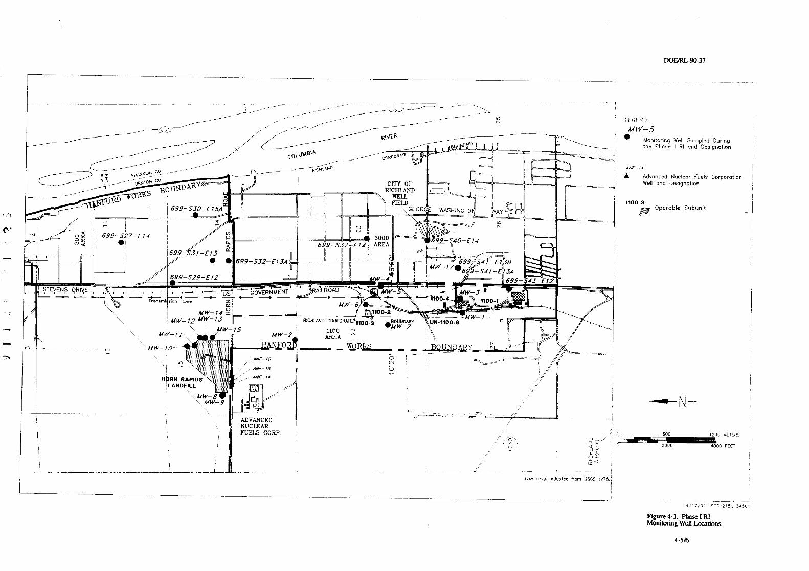
DOF4RL-90-37
I
- -_ -- ----- - - s _- -- --^-- - - ,
-^^i^ ^^RIVER
^
^ -- -'DARY
Moniforing Well Sampled Duringx e u _ the Phose I RI and Designation
COLUMg^ACORPORA7E
RIGHUND
C p ratloneGO
Advanced Nuclear Fue ls or oE n
AB̂ENtON I,L%JJ Well and De g tlon
BOUNnARY^ RICHLAND
si na'
r- MELLORD i I FtELD 1100-3
O p erable SubunitfY 699-5^-E15A GEORGE WASHINGTO W^ UUUUi ^ ^ _qy
^ 0 6 699-S27-E74 3000
RF
699-53E14 AREA
^699-^-E73
• 699-532-E13A 699547 E 1 BTF F MW-170
69
//
9-S41-E73A699-529-E12 J MW-4 699- 43-E12
STEVENS RIVE 5RALROAD_ US GOVENMENT W- -^' MW-3- ~- - - Trnsmi sion Line ^ ^
-• MW-6 •__ +11000 1100-1
MW- 14 = as __ N1100_2 _MMW-13 RICHIAND CORPORATE -Y W- a
^ A^W- 12 1100-3 aoDNOnRY UN-1100-8•M6Y-7
1100\ MW-11
MW-15MW-2 AR^
---- o MW
EA
+''^
R^, ^
M \\ \ . ^.^^j; ANF-16N
OW^
.wF-rs
`r • /^ I ^ ^HPRN RAPIDS i11VF-14
^.,LANDfILL
_-MW-9
. --- ^ ADVANCEDNUCLEARFUELS CORP. 600 1200 METERS
0 2000 4000 FEET
=1 IU G ^ ^
C
Has< map: oCOO^ed bom JSGS 1378. ^ ',
4/17/91 9031215\ 3456,
Figure 4-1. Phase I RIMonitoring Well Locations.
4-5/6
DOE/RL-90-37
4.2.12 Activity lb-1100-EM-1 Operable Unit Ground Water Elevation Summary.
Activixy Objective: The objective of this activity is to develop ground-waterpotentiometric surface maps of the unconfined aquifer for all ground-water elevation datacollected during the period of January through December 1990.
ACtlyltV Descriytion: Ground water elevation data collected on a monthly basis,between the period of January through December 1990, will be plotted. Potentiometricsurface maps of the unconfined aquifer will be developed from this data to observefluctuations over the time period of the sampling.
SamgWg Locations. Frequencies. and Analvsis: Ground water elevations areavailable from the monitoring wells in the 1100 and 300 Areas. Simultaneous measurementswere made once a month at each of the wells. Ground-water elevation measurementscollected at the wells will be added to the data base and potentiometric surface maps of theunconfined aquifer will be developed by the data evaluation task for hydrogeologic data(Section 4.9.3).
4.2.13 Activity lc-0perable Unit Ground-Water Monitoring.
Activity Objective: The objective of this activity is to provide a ground-water" monitoring schedule for the existing and additional 1100-EM-1 Operable Unit monitoring
wells.
Activity Description: Ground-water samples and static water levels will be obtainedfrom all existing and additiona11100-EM-1 Operable Unit monitoring wells. Analyticalresults will be used to further define background water quality, monitor down-gradientwater quality, and determine if additional stages of monitoring well installation are requiredto delineate operable unit ground-water contamination. The data collected by this activity
- will be evaluated by the data evaluation task for hydrogeologic data (Section 4.9.3).
- Sampling equipment, sample designation, and handling procedures are referenced inChapters 4 and 5 and Tables 2 and 3 in the QAPP (see Appendix A). The parameters listedin Table 4-1 may be modified upon the completion of Activity I as Ground-WaterMonitoring Interim Report.
Sample Location. Frequencv, and Analvsis: Ground water will be sampled from thewells listed in Table 4-1 and any from any wells installed during the Phase II RI accordingto the schedule also provided in Table 4-1. The locations of existing wells are shown inFigure 4-1. Samples will be analyzed for parameters listed in Table 4-1 according tomethods referenced in Table 1 in the QAPP (see Appendix A). The parameters listed inTable 4-1 may be modified upon the completion of Activity la, Ground-Water MonitoringInterim Report.
4-7
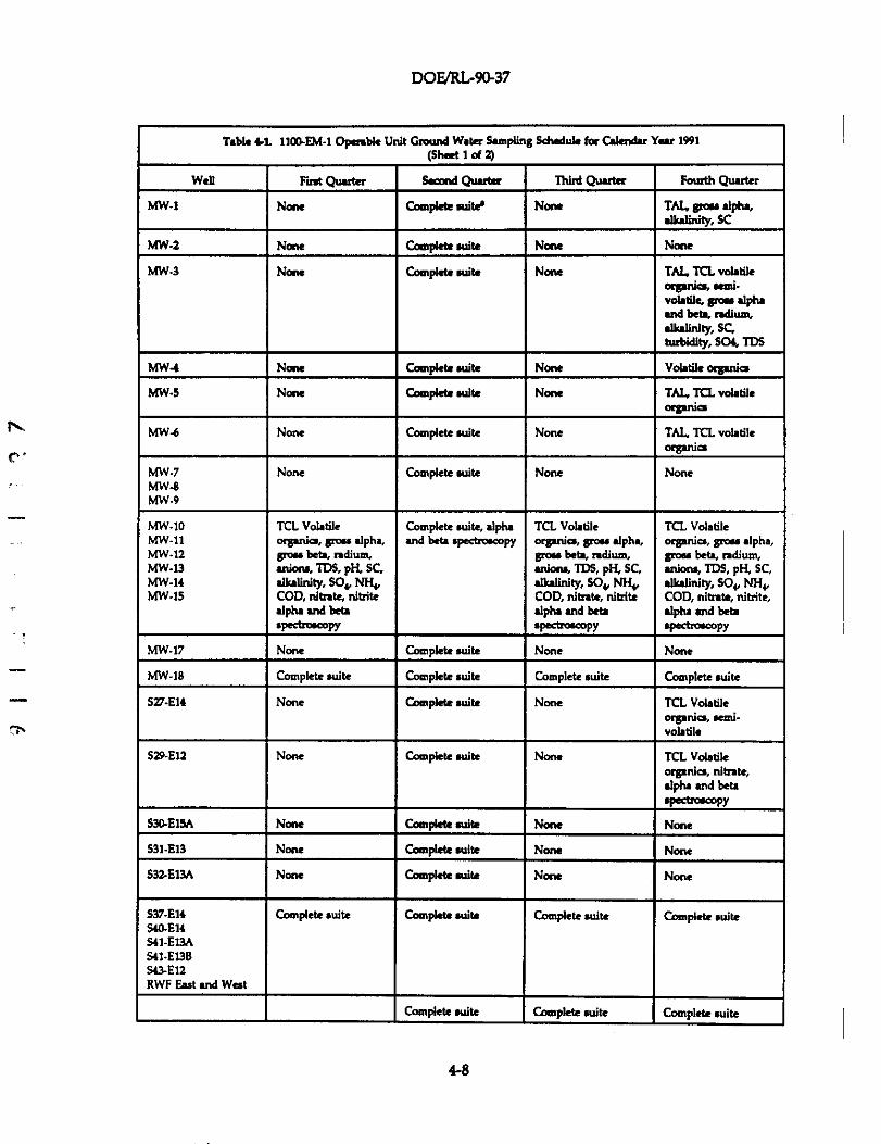
DOF/RL-9a37
N,
C.
Table 4-1. 1106EM-1 Operable Unit Ground Water Sampling Schedule for Cakndar Year 1991(Sheet 1 of 2)
Well First Quarter Sem'd Quarter Third Quarter Fourth Quarter
MW-1 None Complete a+it1 None TAl„ gtoss dPha,alkalinlty, SC
MW-2 None Completesuite None None
MW-3 None Complete suite None TAI, TCL volatilei lorgan cs, sam .
volatile, gmr alphaand beta, ndium,alkalinity, SC,turbidity, SO4, TDS
MWAI None Compktesuite None Volatikorganio
MW-S None Compbte suite None T/t1. TCL volatileorganin
MW-6 None Complete suite None TAL, TCL volatileoegania
MW-7 None Complete suite None NoneMW-8MW-9
MW-10 TCL Volatile Complete suite, alpha TCL Volatile TCL VolatileMW-11 organics, gross alpha, and beta spectroscopy organics, goss alpha, organics, gioss alpha,MW-12 gross bets, ndium, grds beta, radium, gaas beta, odium,MW.13 anions, TDS, PH, SC, anions, TDS, pH, SC, anions, TDS, PH, SC,MW-14 alkalinity, SOs, NFI„ alkalinity, SO4, NH4, alkalinity, 804, NH4,MW.15 COD, nitnte, nitrite COD, nitrate, nitrite COD, nitrate, nitrite,
alpha and beta alpha and beta alpha and betaspectroscopy spectroscopy spectroscoPY
MW-17 None Complete suite None None
MW-18 Complete suite Complete suite Complete suite Complete suite
527-E74 None Complete suite None TCL Volatileorganics, semi-Volatile
S29-E12 None Complete suite None TCL Volatileorganics, nitrate,
alpha and beta
W«troscoPY
S34E15A None Complete suite None None
S31-E13 None Complete suite None None
S32E13A None Complete suite None None
537-E74 Complete suite Complete suite Complete suite Complete suiteS40-E14541-EL9AS41-E13ES43-E12RWF East and West
Complete suite Complete suite Complete suite
4-8
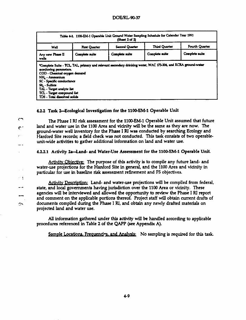
DOF/RL-90-37
Table 4L 1100.FM-1 Operable Unit Ground Water Sampling Schedule for Calendar Year 1991(Sheet 2 of 2)
well r•ir.t Quarter s.=a Quatter 'n+rd Quarter rourti, Quarter
Any new Plrse ll Comp4te wits Complete suite Compkte suite Comple6e rui0ewdb
'Campkte Suite - TCI,. TA4 peiwry and relevant secondary ddnidns water, WAC 1T1•3o1, and RCRA gound-watQ
mon+toring parameters.COD - Chemiol aay$en demandNl% -AmmaJumSC - Spsefic conductanceSo4 - SulfateTAL - Target analyte IbtTCL - Target mmpoamd list7DS - Total dioolved solids
4.2.2 Task 2--Ecological Investigation for the 1100-EM-1 Operable Unit
An The Phase I RI risk assessment for the 1104EM-1 Operable Unit assumed that futuret. • land and water use in the 1100 Area and vicinity will be the same as they are now. The
ground-water well inventory for the Phase I RI was conducted by searching Ecology andHanford Site records; a field check was not conducted. This task consists of two operable-unit-wide activities to gather additional information on land and water use.
4.2.2.1 Activity 2a-Land- and Water-Use Assessment for the 1100-EM-1 Operable Unit.
Activity Objective: The purpose of this activity is to compile any future land- andwater-use projections for the Hanford Site in general, and the 1100 Area and vicinity inparticular for use in baseline risk assessment refinement and FS objectives.
Activity Description: Land- and water-use projections will be compiled from federal,- state, and local governments having jurisdiction over the 1100 Area or vicinity. These^ agencies will be interviewed and allowed the opportunity to review the Phase I RI report
and comment on the applicable portions thereof. Project staff will obtain current drafts ofdocuments compiled during the Phase I RI, and obtain any newly drafted materials onprojected land and water use.
All information gathered under this activity will be handled according to applicableprocedures referenced in Table 2 of the QAPP (see Appendix A).
Sample Locations. Frequend-s. and Analvsis: No sampling is required for this task
4-9
c*
c
;11.
DOE/RL-90-37
4.2.2.2 Activity 2b-Well Inventory Refinement for the 1100-EM-1 Operable Unit.
Activity Objective: The purpose of this activity is to refine the information gathered
during Phase I activities on ground-water withdrawal points within the potentially
contaminated downgradient direction to determine if additional existing wells should be
included in the Phase II RI ground-water investigation.
Activity Description: The survey will be conducted by a door-to-door search
collecting information on location, current owner, current use, well condition, and well log
availability. Wells will be photographed to document the current condition. Wells will also
be sounded to determine the total depth and water level. Ecology files will be revisited for
any new wells installed and a review will be conducted of the United States Geologic
Survey (USGS) well files.
All information collected during the survey will be documented and handled in
compliance with the procedures referenced in Table 2 of the QAPP (see Appendix A).
;;ampkg Locations. Frequencies and Analysis: No sampling is required under this
task A one time survey will be conducted in Township 10 N, Range 28 E, sections 9, 10, 11,
14, 15, 16, 21, 22, 23, 26, 27, 28, and the northern half of sections 33, 34, and 35. All well
locations not currently identified with north-south/east-west (NS/EW) coordinates and
elevations will be surveyed (see Section 4.2.3.1).
4.2.3 Task 3-Geodetic Control for the 1100-EM-1 Operable Unit
The single activity planned for this task is geodetic surveying within the established
geodetic coordinate system to determine Phase II RI sampling locations.
4.2.3.1 Activity 3a-Geodetic Survey for the 1100-EM-1 Operable Unit.
Activity Objective: The objective of this activity is to document all Phase II RI
sampling point locational data on an operable-unit-wide basis.
Activi , Description: Locational data includes NS/EW Lambert coordinates andelevations in feet (ft) above mean sea level (amsl). Table 4-2 identifies the locational dataneeded for specific sampling methods.
Table 4-2. Survey Data Types for Sampling Locations at the 1100-EM-1 Operable Unit
Sampling Location Survey Data Type
Soil Gas ProbesSurface SamplesSoil BoringsMonitoring or Existing WellsGeophysical TransectsSurface Radiation Transects
NSIEW CoordinatesNS/EW CoordinatesNS/EW Coordinates and ElevationsNSIEW Coordinates and ElevationsNSIEW CoordinatesNSIEW Coordinates
4-10
DOF•/RL-90-37
Applicable procedural controls for geodetic surveying and equipment, and field datadocumentation are referenced in Table 2 of the QAPP (see Appendix A).
Sample Locations. Frequencies and Analylis: No sampling will be conducted by this
activity.
4.3 1100-2 TASKS
filevated PCE concentrations were found within a small area of the 11U42 operablesubunit during the Phase I RI soil gas survey. Surface and subsurface soil investigations inthe area of elevated soil gas concentrations did not locate a source. No monitoring wellsare located immediately downgradient from this operable subunit Further investigation isrequired to determine if operable subunit ground water is contaminated. One task isplanned to provide additional characterization:
^ • Task 1-Hydrogeological Investigation for 1100-2.
r••
4.3.1 Task 1-Hydrogeological Investigation for 1100-2
The activities planned for this task include monitoring well installation, and ground-water sampling and analysis.
4.3.1.1 Activity la-Monitoring Well Installation for 1100-2.
Activity Objective: This activity will be conducted in stages. The objective of stage Iis to install a downgradient monitoring well to monitor 1100-2 subunit ground water. Theobjective of stage 2 is to delineate the extent of any significant contamination in groundwater that is attributable to the 1100-2 operable subunit
Activity DescrioHon: One monitoring well will be installed within the upperunconfined aquifer immediately downgradient from 1100-2 operable subunit If anycontamination is present in the ground water at significant levels and it is determined that1100-2 is the source of the contamination, additional wells will be installed to delineate theplume. A pump test may be added if ground water is found to be contaminated and isattributable to the 1100-2 operable subunit
Monitoring wells will be installed according to the procedures referenced in Table 2 ofthe QAPP (see Appendix A).
Sample Location. Fre ency and Analyga: The monitoring well(s) installed by thisactivity will be sampled by Activity 1b. The location of the Stage 1 downgradientmonitoring well is shown in Figure 42. Should additional wells become necessary, wellswould be installed downgradient from the operable subunit The effects of ground-watermounding due to the City of Richland well field operations to the east would need to beconsidered in locating wells, and a sufficient number of wells would need to be installed instages to delineate the extent of the contaminant plume.
4-11
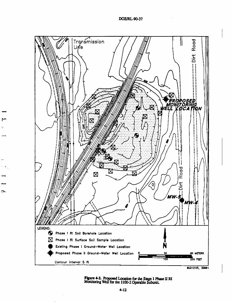
DOFJRI--90-37
"^
Tr smission^ Li e °
^
1 " • ^
OSE ^
E L CA N
V:.
. . . . . . . . . .' .'.^ '^ :•:•::'..
I
II
i ^ ^
; .: . .. . : : :
'. • ^ . . .•. : .7. . . . . .' . .'. ...'. .....' i
....::::::::: ::: ::::::
f ^.
............... .... .......
'.'.'.
...
.^.^^'^^.'.'.'....'.'.'.'.'^'..'.'.'.'•.'
. . ....^ . . .............. o
^o ^TM
LEGEND:
^ Phase I RI Soil Borehole Location
® Phase I RI Surface Soil Sample Location
^ Existing Phase I Ground-Water Well Location N
# Proposed Phase II Ground-Water Well Location o 30 eo weiM
Contour interval 5 ft1 00 200
e031215\ I3aet
FlSnre 4d. prooosed Location for the Stage 1 Phase II RIMafiwrinQ Well for the 110042 Operable SubuniL
4-12
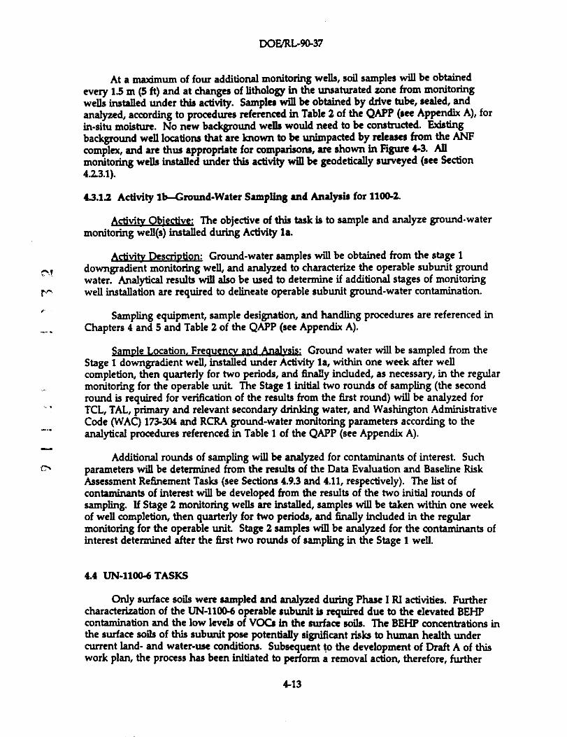
DOE/RL-90-37
At a maximum of four additional monitoring wells, soil samples will be obtained
every 1.5 m (5 ft) and at changes of lithology In the unsaturated zone from monitoring
wells installed under this activity. Samples will be obtained by drive tube, sealed, and
analyzed, according to procedures referenced in Table 2 of the QAPP (see Appendix A), for
in-situ moisture. No new background wells would need to be constructed. Existing
background well locations that are known to be unimpacted by releases from the ANF
complex, and are thus appropriate for comparisons, are shown in Figure 4-3. Allmonitoring wells installed under this activity will be geodetically surveyed (see Section
4.2.3.1).
43.1.2 Activity lb-Ground-Water Sampling and Analysis for 1100-2.
Activity Objective: The objective of this task is to sample and analyze ground-water
monitoring well(s) installed during Activity la.
Activitv Description: Ground-water samples will be obtained from the stage idowngradient monitoring well, and analyzed to characterize the operable subunit groundwater. Analytical results will also be used to determine if additional stages of monitoringwell installation are required to delineate operable subunit ground-water contamination.
Sampling equipment, sample designation, and handling procedures are referenced inChapters 4 and 5 and Table 2 of the QAPP (see Appendix A).
Sample Location. Freque^ and Analysis: Ground water will be sampled from theStage 1 downgradient well, installed under Activity Is, within one week after wellcompletion, then quarterly for two periods, and finally included, as necessary, in the regularmonitoring for the operable unit The Stage I initial two rounds of sampling (the secondround is required for verification of the results from the first round) will be analyzed forTCL, TAL, primary and relevant secondary drinking water, and Washington AdministrativeCode (WAC)173304 and RCRA ground-water monitoring parameters according to theanalytical procedures referenced in Table 1 of the QAPP (see Appendix A).
Additional rounds of sampling will be analyzed for contaminants of interest. Suchparameters will be determined from the results of the Data Evaluation and Baseline RiskAssessment Refinement Tasks (see Sections 4.9.3 and 4.11, respectively). The list ofcontaminants of interest will be developed from the results of the two initial rounds ofsampling. If Stage 2 monitoring wells are installed, samples will be taken within one weekof well completion, then quarterly for two periods, and finally included in the regularmonitoring for the operable unit Stage 2 samples will be analyzed for the contaminants ofinterest determined after the first two rounds of sampling in the Stage I well.
4.4 UN-1100-6 TASKS
Only surface soils were sampled and analyzed during Phase I RI activities. Furthercharacterization of the UN-11046 operable subunit is required due to the elevated BEHPcontamination and the low levels of VOCs in the surface soils. The BEHP concentrations inthe surface soils of this subunit pose potentially significant risks to human health undercurrent land- and water-use conditions. Subsequent to the development of Draft A of thiswork plan, the process has been initiated to perform a removal action, therefore, further
4-13
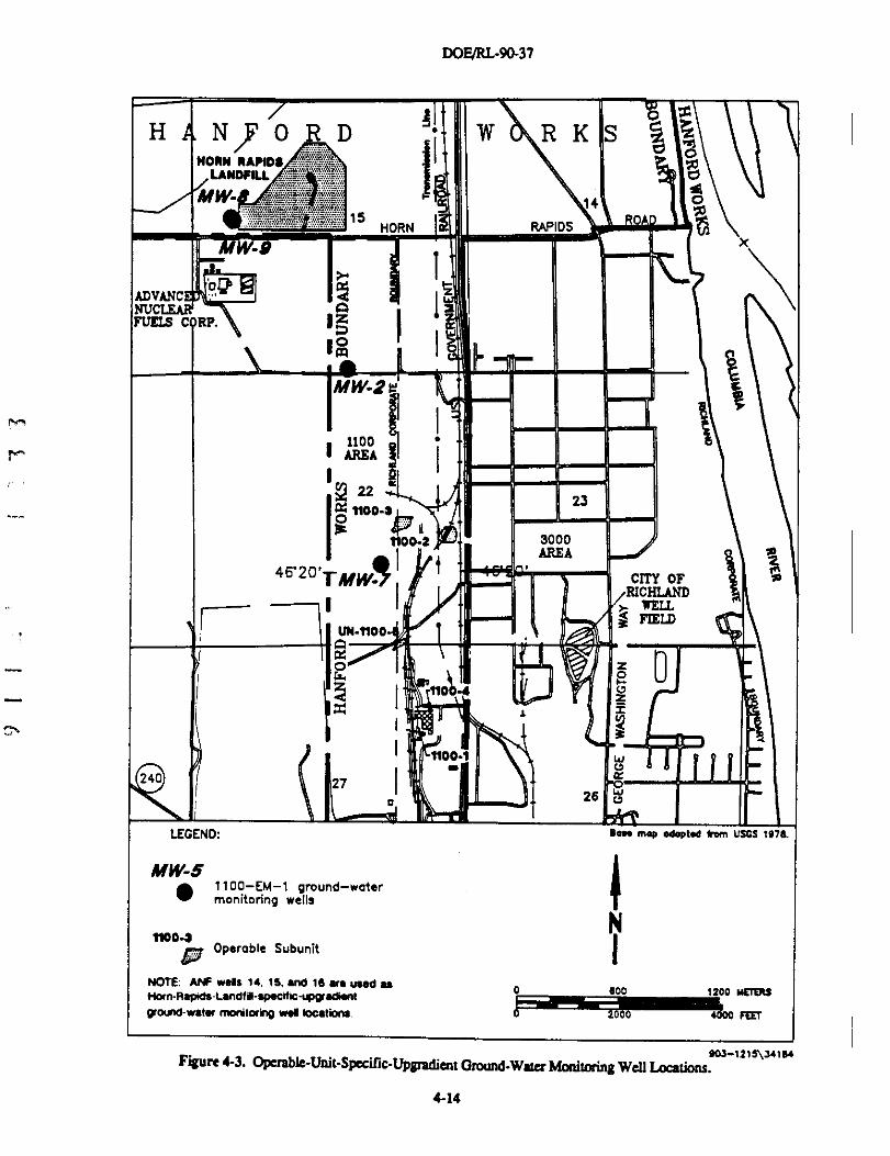
DOFJRl.-90-37
:IN
^x
N F 0 D W R K S,,, . iNOIIN ^t:^,S;:
.. ...LANDFlLL .;:--°:•i` C7
_:......:7....... .::':'it'' o4'•ig`iL:i^Yri$$::..,-.a,j..e.y 1S ^Q
HORN RAPIDS
_v X
ADVANC
^.:^riF rz
\NUCLEAR AFUELS C RP. 1z
:D0m sMW-2
1100
' "REA^221100-i
23
3000
46'20'TMW.j t
AREA
CTfY OFRICHLAfTD
IIEI L
UN-1100•
VI
t100•1 W
240 270 26
LEGEND: aeM mup edaptea hem USGS 1978,
MW-5 ^• 1100-EM-1 ground-water
monitoring wells
Nn0D-ap Operable Subunit
NOTE: Al•IF wele 14, 15, and 16 are used as 0 600 1200 ME7G5tiom-Rapiae-LanafiM-epecific-uppradient
pround-water nqntorifp was la0atione 2 0 00 iEET
FiQure4-3. Gperable-Unit-S tC-^3 1t1a^^41e4
Pa^ UDB^+mt Ground-Watu Monitoring Well Loations.
4-14
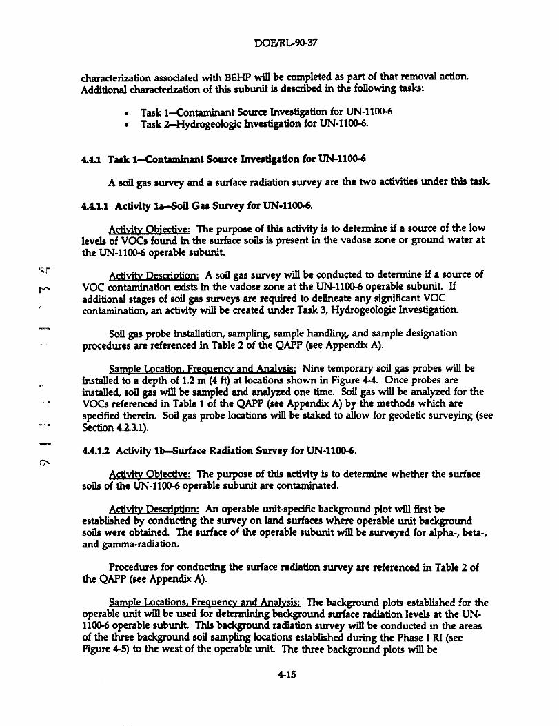
DOE/RL-9Q37
characterization associated with BEHP will be completed as part of that removal action.
Additional characterization of this subunit is described in the following tasks:
• Task 1-Contaminant Source Investigation for UN-1100-6
• Task 7-Hydrogeologic Investigation for UN-1100-6.
4.4.1 Task 1-Contaminant Source Investigation for UN-1100-6
A soil gas survey and a surface radiation survey are the two activities under this task.
4.4.1.1 Activity la-Soil Gas Survey for UN-1100-6.
Activity O¢jective: The purpose of this activity is to determine if a source of the low
levels of VOCs found in the surface soils is present in the vadose zone or ground water atthe UN-1100-6 operable subunit
ActivitKDescription: A soil gas survey will be conducted to determine if a source of
r.^ VOC contamination adsts in the vadose zone at the UN-1100-6 operable subunit. Ifadditional stages of soil gas surveys are required to delineate any significant VOCcontamination, an activity will be created under Task 3, Hydrogeologic Investigation.
Soil gas probe installation, sampling, sample handling, and sample designationprocedures are referenced in Table 2 of the QAPP (see Appendix A).
Sample Location. Frequencv and Analysis: Nine temporary soil gas probes will beinstalled to a depth of 1.2 m (4 ft) at locations shown in Figure 4-4. Once probes areinstalled, soil gas will be sampled and analyzed one time. Soil gas will be analyzed for theVOCs referenced in Table I of the QAPP (see Appendix A) by the methods which arespecified therein. Soil gas probe locations will be staked to allow for geodetic surveying (seeSection 4.2.3.1).
4.4.1.2 Activity lb-Surface Radiation Survey for 1JN-1100-6.
Activity Objective: The purpose of this activity is to determine whether the surfacesoils of the UN-1100-6 operable subunit are contaminated.
Activity Description: An operable unit-specific background plot will first beestablished by conducting the survey on land surfaces where operable unit backgroundsoils were obtained. The surface o$ the operable subunit will be surveyed for alpha-, beta-,and gamma-radiation.
Procedures for conducting the surface radiation survey are referenced in Table 2 ofthe QAPP (see Appendix A).
Sample Locations. Freque^ and Ana)y;:ij; The background plots established for theoperable unit will be used for determining background surface radiation levels at the UN-1100-6 operable subunit This background radiation survey will be conducted in the areasof the three background soil sampling locations established during the Phase I RI (seeFigure 4-5) to the west of the operable unit The three background plots will be
4-15
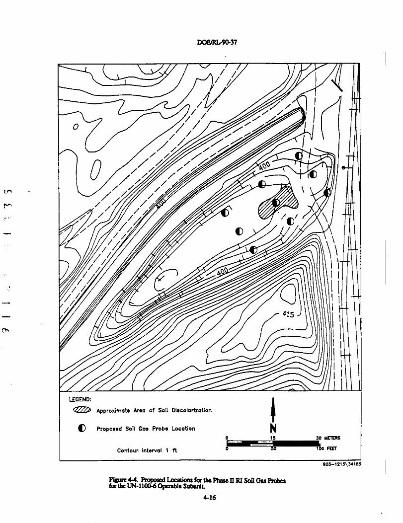
DOF/RL90-37
r^
/.
L11
LEGEND:
® Approximate Area of Soil Discolorization
IV Proposed Soil Gas Probe Location
Contour interval 1 ft
;^;
IN
0 iS 30 HE7ERS
0 F[LT
e03-1215\341e5
Fiaare 44. Proposed L.oeuions for the Fhw 11 RI Soil On Probesfor the UN-11G0-6 Opaable Submrit
4-16
DOF/R1r9Q-37
XOIIN BA/IDi
"LANRL
NDFILL . ....... •.:;;;'^ ^--1 :•;:^:;;^ . :;:: `'
;4::A^:a:•::^ ::.^"z;•;a:^;.• ^k-p;;. ^
1514
i;^;i='^±".°.•::^':c^iti''^..HORN RAPIDS
ADVANCED
FUEIB oRP.`N e
IA
°°( 11I
j I^ ,^
Fm 22 ^i
noo-s 23
^^ oo- 3000AREA
^
^
4620' ^iRICHLAND
-- ^ ^
^ UII HOO I 1
WELL
^^- -
^- g` nzbI
01o _
rBAP-? o=_
U I
^
2726 0
1100-0,r^,, Operable Subunit
BAP-?Background Soil and Borehole
^ Designation Sample Locations
N I
g`s^
NOTE M.. map eeeOfie eem USGS W)e.
^ Two background surface soil sampleswere collected at each location inthe following directions measuredin feet from the borehole:
N DP-7 75 ft. - 324'I BAP-2 127.5 ft. - 276
HRL-1 170.5 ft. - 31B
0 eoo 12oo METERS
1000 toao vecr
903-1215\34ie3
Fi`are 1-S. Bukgrtmnd Soil SwplinSLacatdooa fa the 1100-EM-1 Operable Uoit.
4-17
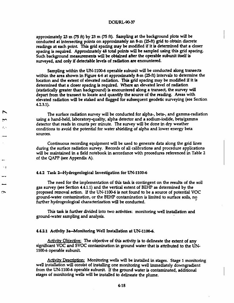
DOE/RL-90-37
approximately 23 m (75 ft) by 23 m (75 ft). Sampling at the background plots will beconducted at intersecting points on approximately an 8-m (25-ft) grid to obtain discretereadings at each point This grid spacing may be modified if it is determined that a closerspacing is required. Approximately 48 total points will be sampled using this grid spacing.Such background measurements will be obtained after the operable subunit itself issurveyed, and only if detectable levels of radiation are encountered.
Sampling within the UN-1100-6 operable subunit will be conducted along transectswithin the area shown in Figure 4-6 at approximately 8-m (25-ft) intervals to determine thelocation and the extent of elevated radiation. This grid spacing may be modified if it isdetermined that a closer spacing is required. Where an elevated level of radiation(statistically greater than background) is encountered along a transect, the survey willdepart from the transect to locate and quantify the source of the reading. Areas withelevated radiation will be staked and flagged for subsequent geodetic surveying (see Section4.2.3.1).
^ The surface radiation survey will be conducted for alpha-, beta-, and gamma-radiationusing a hand-held, laboratory-quality, alpha detector and a sodium-iodide, beta/gammadetector that reads in counts per minute. The survey will be done in dry weatherconditions to avoid the potential for water shielding of alpha and lower energy betasources.
Continuous recording equipment will be used to generate data along the grid linesduring the surface radiation survey. Records of all calibrations and procedure applicationswill be maintained in a field notebook in accordance with procedures referenced in Table 2of the QAPP (see Appendix A).
4.4.2 Task 2-Hydrogeological Investigation for UN-1100-6
_ The need for the implementation of this task is contingent on the results of the soilgas survey (see Section 4.4.1.1) and the vertical extent of BEHP as determined by the
s^ proposed removal action. If the UN-1100-6 is not found to be a source of potential VOCground-water contamination, or the BEHP contamination is limited to surface soils, nofurther hydrogeological characterization will be conducted.
This task is further divided into two activities: monitoring well installation andground-water sampling and analysis.
4.4.2.1 Activity 3a-Monitoring Well Installation at UN-1100-6.
Activity Qbiective: The objective of this activity is to delineate the extent of anysignificant VOC and SVOC contamination in ground water that is attributed to the UN-1100-6 operable subunit
ActiviEy Description: Monitoring wells will be installed in stages. Stage 1 monitoringwell installation will consist of installing one monitoring well immediately downgradientfrom the UN-1100-6 operable subunit If the ground water is contaminated, additionalstages of monitoring wells will be installed to delineate the plume.
4-18
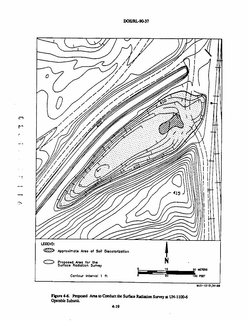
DOF/RLA0-37
c1
r
1
F'igar6 4-6. Proposed Area to Conduct the Surfaa Radiation Survey at UN-I1U0-6Operable Subunit.
903-7275\34166
4-19
DOM-9a37
Monitoring well installation procedures are referenced in Table 2 of the QAPP (seeAppendix A).
Samvle Location. Frequencv and Analysis: Should this task become necessary, theStage I monitoring well will be installed immediately downgradient from the operablesubunit as shown in Figure 4-7. If required, a sufficient number of wells would need to beinstalled in stages to delineate the extent of the contamination. If any monitoring wells areinstalled by this activity, soil samples will be obtained every 1.5 m(5 ft) and at changes oflithology in the unsaturated zone at a maximum of four additional monitoring wells.Samples will be obtained by drive tube, sealed, and analyzed according to proceduresreferenced in Table 2 of the QAPP (see Appendix A) for in-situ moisture. The effects ofground-water mounding due to City of Richland well field operations to the east wouldneed to be considered in locating wells. No new background wells would need to beconstructed. All wells installed by this task will be geodetically surveyed (see Section4.2.3.1).
4.4.2.2 Activity 3b-Ground-Water Sampling and Analysis at UN-1100-6.
Activity Objective: The purpose of this activity is to sample and analyze the ground-water monitoring wells installed during Activity 3a (see Section 4.4.2.1).
-' Activity Description: Ground-water samples will be obtained from the Stage 1downgradient well, and analyzed to characterize operable unit ground water. Analyticalresults will be used to determine if additional stages of monitoring wells are required todelineate operable subunit ground-water contamination.
Sampling equipment, sample designation, and handling procedures are referenced inChapters 4 and 5 and Table 2 of the QAPP (see Appendix A).
- Sample Location. Frequency and Analysis: Ground water will be sampled from theStage 1 downgradient well, installed in Activity 3a (see Section 4.4.2.1), within one week
- after well completion, then quarterly for two periods, and then included, as necessary, in-^. the regular monitoring for the operable unit The Stage 1 initial two rounds of sampling
(the second round is required for verification of the results from the first round) will beanalyzed for TCL, TAL, primary and relevant secondary drinking water, and WAC 173-304and RCRA ground-water monitoring parameters according to analytical methods referencedin Table I of the QAPP (see Appendix A).
Additional rounds of sampling will be analyzed for contaminants of interest Suchparameters will be determined from the results of the Data Evaluation and Baseline RiskAssessment Refinement Tasks (see Sections 4.9.3 and 4.11, respectively). If Stage 2monitoring wells are installed, samples will be taken within one week of well completion,then quarterly for two periods, and then included, as necessary, in the regular monitoringfor the operable subunit Stage 2 samples will be analyzed for contaminants of interest
4-20
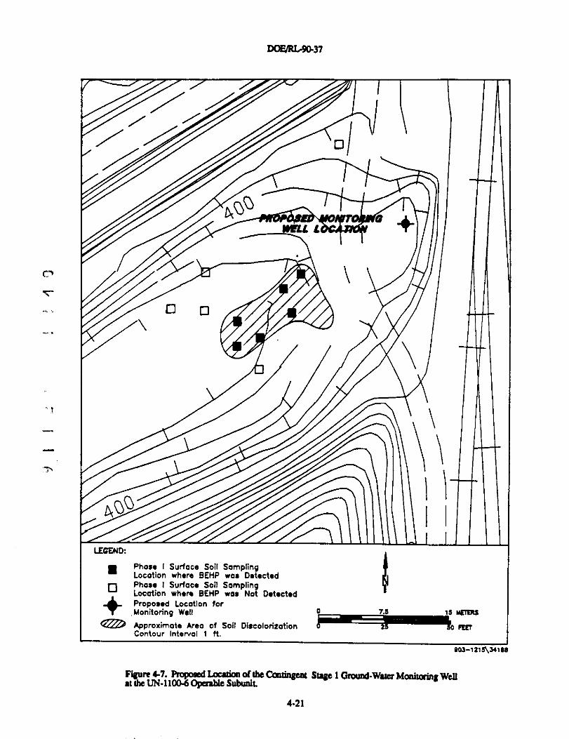
D0EJRL90-37
r̂
^oo
n o
oi
+
7,
LEGEND:
n Phase I Surface Soil SamplingLocation where BEHP was Detected
0Phase I Surface Soil Sampling
+ Location where BEHP was Not DetectedProposed Location forMonitoring Well o,?.^ 13 wEIERS
Approximate Area of Soil Diuoloriiation 6̂ -Z. FEETContour Interval 1 ft.
Figure 4-7. Froposed Loeadm of the Caotingeat Stage 1(iround-Wwa Monitoring Wellat the UN-1100-6Operable SubuuL
4-21
DOE/RL-90-37
4.5 HORN RAPIDS LANDFILL TASKS
Horn Rapids Landfill operable subunit requires further investigation due to theelevated contaminants, such as TCE and nitrate, in ground water, and PCB and chromiumin soils. This investigation is divided into the following tasks:
• Task 1-Contaminant Source Investigation for Horn Rapids Landfill• Task 2-Pedological Investigation for Horn Rapids Landfill• Task 3-Hydrogeological Investigation for Horn Rapids Landfill.
Descriptions of these tasks are provided below.
4.5.1 Task 1-Contaminant Source Investigation for Horn Rapids Landfill
_ Additional geophysical surveys and soil gas monitoring network installation andsampling, are the two activities planned for this task.
4.5.1.1 Activity la-Geophysical Surveys at the Horn Rapids Landfill.
^ Activity Objective: The objective of additional geophysical surveys at the HornRapids Landfill as defined by EPA is to detect the presence of concentrations of 10 or more55-gal steel drums.
Activi , Description: It has been alleged that as many as 200 55-gal steel drumscontaining carbon tetrachloride may have been buried at the landfill (DOE-RL 1989). Thisactivity will use geophysical techniques to delineate areas containing metallic materials thatmay correspond to concentrations of 10 or more 55-gal steel drums.
" Forward modeling methods will be used to characterize the theoretical MAG response_ to a threshold target of ten 55-gal drums. A qualitative evaluation will be used for EMI and
GPR techniques. Magnetometry (MAC) and electromagnetic induction (EMI) surveys willbe conducted and the resulting data will be analyzed in the field to identify specificlocations that may contain a concentration of at least 10 drums. A ground penetratingradar (GPR) survey will then be performed in the areas identified by the MAG and EMIsurveys.
Procedures for EMI and GPR surveys are referenced in Table 2 of the QAPP (seeAppendix A). WHC procedures for MAG surveys are under development MAG surveyprocedures will be a WHC procedure or a participant contractor/subcontractor proceduredeveloped in accordance with Section 4.1 in the QAPP (see Appendix A).
Sampling Location. Frequencv and An ysis: The location and frequency of theadditional geophysical survey work is dependant on a review of the edsting geophysicalinformation. It is anticipated that work will be performed on a 3-m (10-ft) grid spacing forMAG and EMI surveys and a 1.5-m (5-ft) line spacing for GPR surveys where required.
4-22
DOE4U:-90-37
4.5.1.2 Activity 1b--Soil Gas Monitoring Network Installation andSampling at Horn Rapids Landfill.
Activjlyy Objective: The purpose of this activity is to install a system to detect anychanges in concentrations of VOG in soil gas being generated within the landfill thatwould indicate a sudden release of buried liquid solvents. A contingency plan will bedeveloped as part of the Phase ill FS.
Activity Descrivtion: A permanent soil gas monitoring network will be installed tomonitor for the release of vapors from the rupture of suspected buried drums of volatileliquids. Additional temporary soil gas survey locations may be required under Task 3,Hydrogeological Investigation, if the source of TCE in the local ground water is attributedto the landfill.
Soil gas probe installation, soil gas sampling, sample handling, and sampledesignation procedures are referenced in Chapters 4 and 5 and Table 2 of the QAPP (seeAppendix A).
Sampling Location. Freque^ and Analysis: Thirty-five permanent soil gas probeswill be installed on a 766m (250-ft) grid to a depth of four feet as shown in Figure 4-8. Soilgas probes will be sampled within one week of completion, and then sampled everyquarter. Soil gas will be analyzed for VOCs according to the procedures referenced inTable 1 of the QAPP (see Appendix A). Soil gas probe locations will be surveyed (seeSection 4.2.3.1).
4.5.2 Task 2--Pedological investigation for Horn Rapids Landfill
Two activities are planned for this task: PCB delineation and EPA-directed additional-- subsurface soil sampling.
4.5.2.1 Activity 2a-PCB Delineation at Horn Rapids Landfill.^
Activity Objective: The purpose of this activity is to delineate the lateral and verticalextent of PCB contamination in soils at Horn Rapids Landfill operable subunit in thevicinity of Borehole HRL-4.
ActivitXDescription: Additional soil samples will be collected in stages to accuratelydefine the lateral and vertical extent of PCB contamination.
Surface sampling, soil boring installation, sampling equipment, sample handling, andsample designation procedures are referenced in Chapters 4 and 5 and Table 2 of the QAPP(see Appendix A).
Sampling Location and Freq}lencv: The locations of Stage I surface and subsurfacesamples are shown in Figure 4-9. If additional stages of soil sampling are required todelineate the extent of contamination, locations will be detenn-tined upon the results ofStage I sampling and analysis. Subsurface hand-augered borings will be completed to adepth of 1.2 m (4 ft). Samples will be collected at 0.3, 0.6, and 1.2 m (1, 2, and 4 ft) belowthe surface.
4-23
DOFJRL-90-37
This page is intentionally left blank
rn
4-24
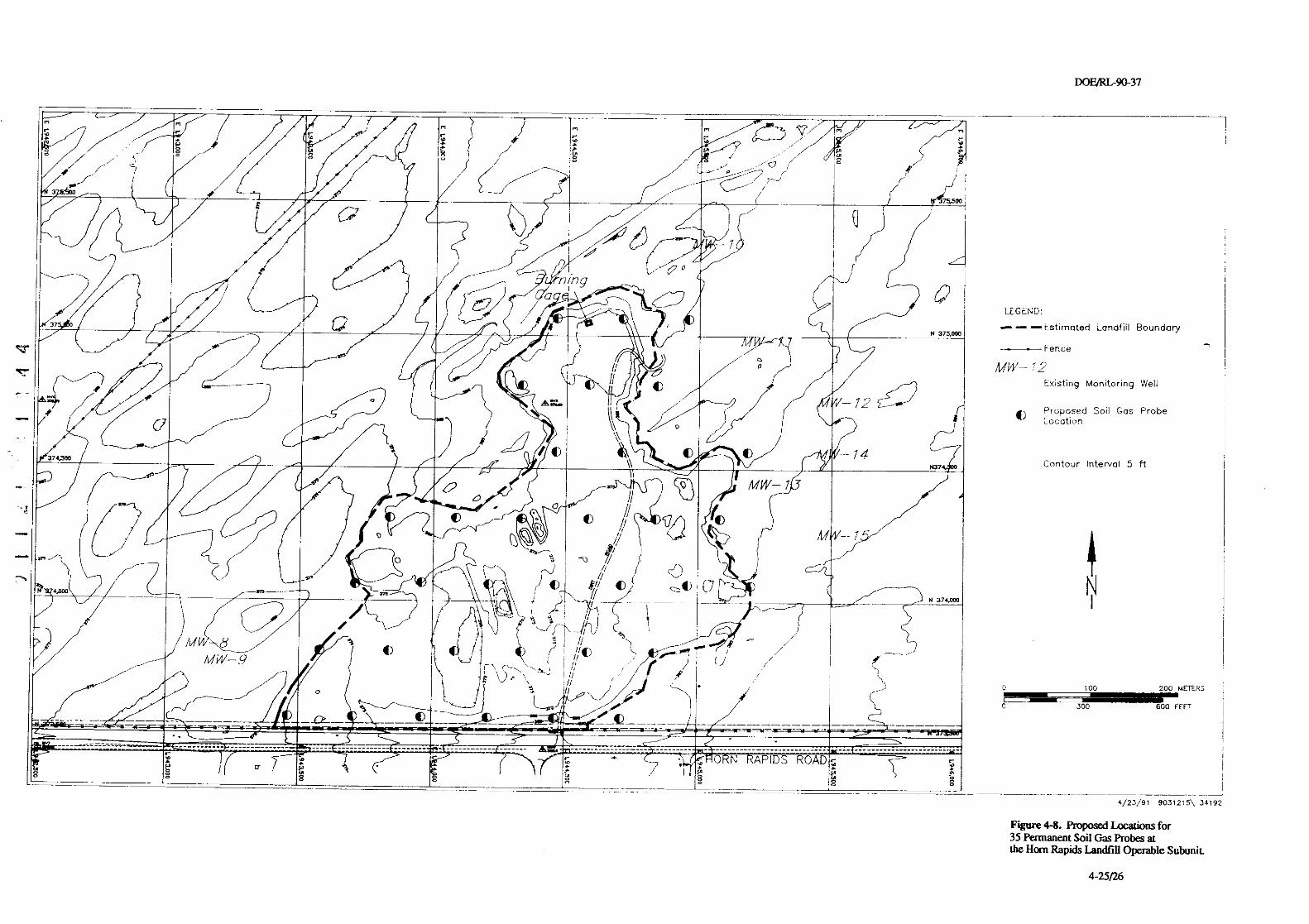
DOP/RL.90-37
<^ -- -- - - -^ r r / m m
^ ^m m
+/Q
°O3 4^1Ce^
-
40^ln
^
/
ing
^ ,
< fl\ N 375,000
D.LEG;h
tstimated Landfill Boundary
F
'
0
°
2r
ence
MW 72Existing Monitoring Well
Pro osed Soil Gas ProbeCI Location
374.^\\
- 14J Contour Interval 5 ft
.AN_ n ^ ^o i ^^^/ ^ a^ o LI N
-1
%fc
o
/
e too 200
0 300 600 f
----- --- - -- -^- ---o -- ---' - ------- ------------ ------ -______ _____________ ________ ________ __- 7 7 7 7 7 7 7 7
A
P
a .
_
I
_______________ _ __________--________-____ _-
0 N APIDS ROAD-_-______
u-- - -- -^- - -
AEiER>'
=E7
- ---- --------^-------- 4/23/91 9031215\ 34192
Figure 4-8. Proposed Locations for35 Permanent Soil Gas Probes atthe Horn Rapids Landfill Operable SubuniL
4-25/26
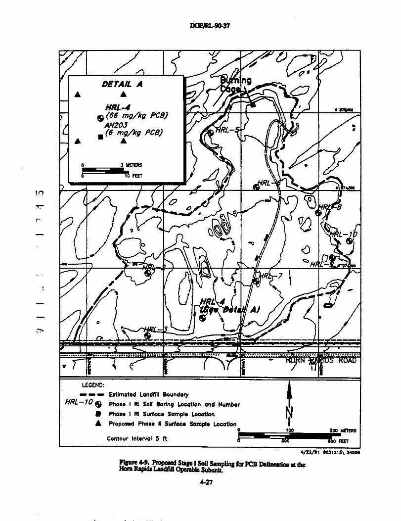
naeRU.9a3'1
Vf
^f,
DETA/L A
V;*l
ng
♦ A
rL
^ r rraeoo^ (66 my1kg PCB)
^ (62mg/kg PCB)A ♦
F
a J MflER4
^10 rErrRL
^ao
°Lo f, e
9Q
C-
// R7
HRL ^1 AJ
. ',
-^-- - - - .... ....... _. ------- - ----- ----.
•v I
LECEND:
- - - Estimated Landfll BoundaryHRL-10 19 Phase I RI Soil Boring Location and Number
n Phase I RI Surface Sample Location
A Proposed Phase II SuAacn Sample Location0 100 200 MER115
Contour Interval 5 it FW
4/21/11 90]1219\ 34559
SoU} RapidtLdfdOppabk SabuNt-p^
for PCB Delimstioo at the
4-27
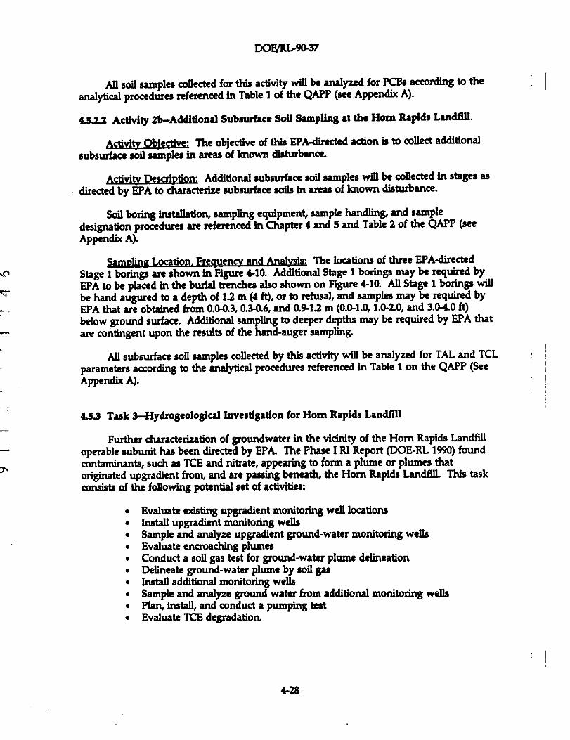
DOE/RLA0-37
AII soil samples collected for this activity will be analyzed for PCBs according to the
analytical procedures referenced in Table I of the QAPP (see Appendix A).
4.52.2 Activity 2b-Additional Subsurface Soil Sampling at the Horn Rapids Landfill.
ActviEy Qbective: The objective of this EPA-directed action is to collect additional
subsurface soil samples in areas of known disturbance.
ActivitXDes tion: Additional subsurface soil samples will be collected in stages as
directed by EPA to characterize subsurface soils In areas of known disturbance.
Soil boring installation, sampling equipment, sample handling, and sample
designation procedures are referenced In Chapter 4 and 5 and Table 2 of the QAPP (see
Appendix A).
5=pbg Location, Frequencv and Analvsis: The locations of three EPA-directed
Stage 1 borings are shown in Figure 4-10. Additional Stage I borings may be required by
EPA to be placed in the burial trenches also shown on Figure 4-10. All Stage 1 borings will
be hand augured to a depth of 1.2 m (4 ft), or to refusal, and samples may be required by
EPA that are obtained from 0.0-0.3, 0.3-0.6, and 0.9-1.2 m (0.0-1.0,1.00.2.0, and 3.0-4.0 ft)
below ground surface. Additional sampling to deeper depths may be required by EPA that
are contingent upon the results of the hand-auger sampling.
All subsurface soil samples collected by this activity will be analyzed for TAL and TCLparameters according to the analytical procedures referenced in Table 1 on the QAPP (SeeAppendix A).
4.53 Task 3-Hydrogeological Investigation for Horn Rapids Landfill
Further characterization of groundwater in the vicinity of the Horn Rapids Landfilloperable subunit has been directed by EPA. The Phase I RI Report (DOE-RL 1990) foundcontaminants, such as TCE and nitrate, appearing to form a plume or plumes thatoriginated upgradient from, and are passing beneath, the Horn Rapids Landfill. This taskconsists of the following potential set of activities:
• Evaluate existing upgradient monitoring well locations• Install upgradient monitoring wells• Sample and analyze upgradient ground-water monitoring wells• Evaluate encroaching plumes• Conduct a soil gas test for ground-water plume delineation• Delineate ground-water plume by soil gas• Install additional monitoring wells• Sample and analyze ground water from additional monitoring wells• Plan, install, and conduct a pumping test• Evaluate TCE degradation.
4-28
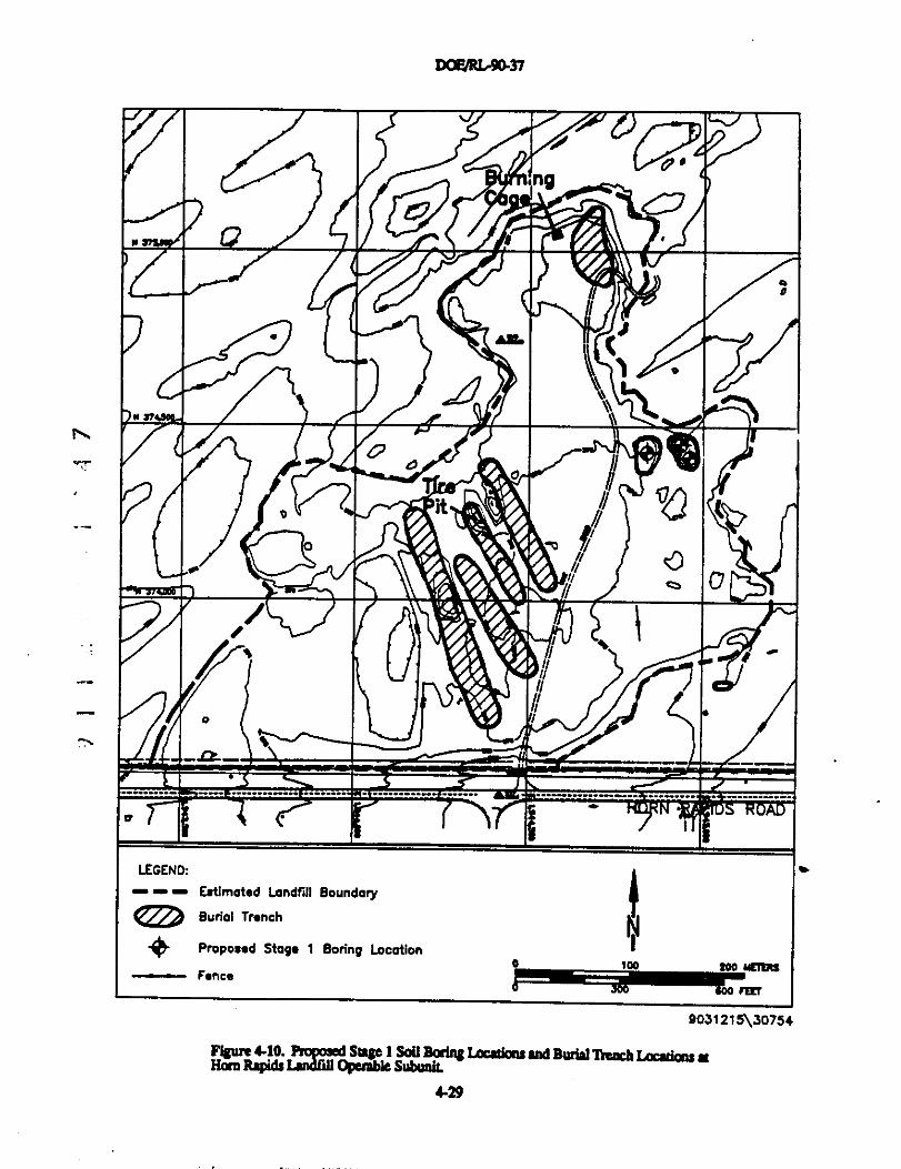
noFJRL.9a^
r*-%
...
C,70e
p
a
dM ^NIP
0 .JIL
^\ ^ e
MA
it
o
^• I
o I
♦-^-
--- - ...... .. - --^- -----
LEGEND:
--- Estimated Landfill Boundary
® Burial Tnnah ^
^ Proposed Staye I Boring Looationa ^aa 20o NE1FRs
Fence300 -^0o rE[T
9031215\30754
MRqldt LPrindf 0=Su^bamL^MLOaaBau and &trid 1YeaC6I.acatim at
4-29
DOFJRL-9437
453.1 Activity 3a-Evaluate Existing Upgradient Monitoring Wells atHom Rapids Landfill.
A!;gft Objective: Due to the contaminant plume known to have emanated from theANF complex, the placement of Hom Rapids Landfill upgradient monitoring wells is crucialto the characterization of Hom Rapids Landfill operable subunit potential contribution toground-water contamination. The purpose of this activity is to evaluate the locations of
existing upgradient monitoring wells installed during the Phase I RI, and to evaluate
existing ANF monitoring wells to determine if additional upgradient wells are necessary.
ActiviRy ikaajption: Ground-water gradient maps prepared in the Phase I RI will beused to determine if existing wells are in optimum locations for upgradient characterization.Well construction and borehole logs for ANF monitoring wells will be obtained andreviewed to determine the usability of ANF monitoring well data for Horn Rapids Landfillcharacterization. This activity will determine if additional upgradient wells are necessary.
Samvle Location. Freguen , and Analysis: No sampling is required by this activity.
4.53.2 Activity 3b-Installation of Additional Upgradient Monitoring Wells atHorn Rapids LandfilL
ACtiNtV Objective: The purpose of this activity is to install additional upgradientmonitoring wells between the Horn Rapids Landfill and potential upgradient ground-watercontamination sources.
Activi Description: The need for the implementation for this task is contingent onthe evaluation of existing upgradient wells conducted in Activity 3a. If additional wells arerequired, this task will consist of installing additional upgradient wells to characterizeground water entering or flowing beneath the Horn Rapids Landfill.
The procedures for installing ground-water wells are referenced in Table 2 of theQAPP (see Appendix A).
Sample Location. Fn:guensy. and Analylis: Should this task become necessary, wellswould be installed upgradient from the operable subunit. Areas proposed for additionalupgradient monitoring wells, denoted as A and B, are shown in Figure 4-11. Whether anynew upgradient wells are installed, and whether they are installed in Area A or Area B (seeFigure 4-11), is dependent on the evaluation of existing upgradient wells on ANF propertyand the determination of responsibility for the South Pit (see Section 4.8.1).
If any monitoring wells are installed by this activity, soil samples will be obtainedevery 1.5 m(5 ft) and at changes of lithology in the unsaturated zone at a maxdmum of fouradditional monitoring wells in the Horn Rapids Landfill vicinity. Samples will be obtainedby drive tube, sealed, and analyzed, according to procedures referenced in Table 2 of theQAPP (see Appendix A), for in-situ moisture. All wells installed by this activity will begeodetically surveyed (see Section 4.2.3.1).
4-30
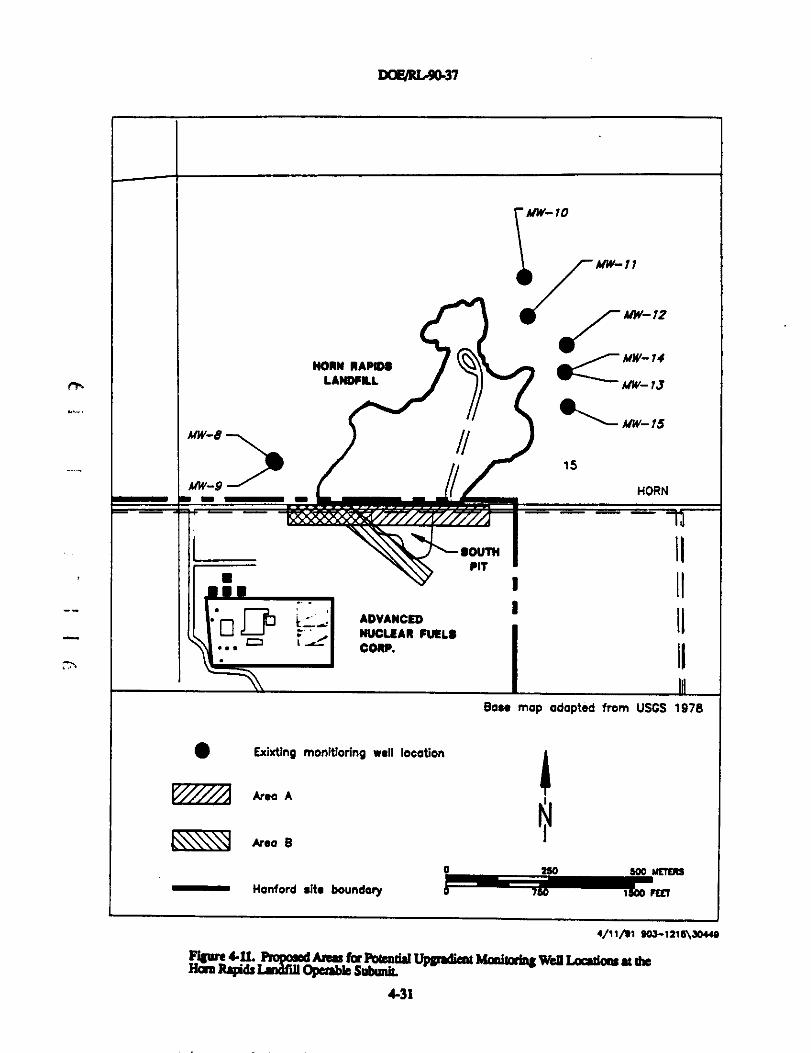
DOFJRL.90-37
rA
10
7MV-17
1_^
MW-1?
HORN IIAPElt
61MW-7I
LANDFLI MW-1J
MW-73MW-B
15
AAV 9
^
HORN
-
soUTH
- - - -
IPIT
n ,
•^ I ip E_` ADVANCED ' IINUCLEAN FUEL!CORP.
Bate map adopted from USGS 1978
^ Exixtinq monitiorinq well location
Area A i
N® Area 9
0 250 600 Yl7faS
Hanford site boundary I MET
4/11/91 90]-1=1e\]044e
1 Rapidsl^uOpbSub^^MO01^Well I oadom at the
4-31
DOF/RLr9a37
4533 Activity 3c-iJpgradient Ground-Water Sampling and Analysis at
Horn Rapids Landfill.
Activb QWective: The purpose of this activity Is to sample and analyze existing
monitoring wells determined in Activity 3a (43.3.1) and upgradient monitoring wells
installed in Activity 3b (Section 4.5.3.2).
Acdvity DescriDtion: Existing monitoring wells determined in Activity 3a (45.3.1) and
those installed in Activity 3b (Section 4.5.3.2) will be sampled and analyzed to determine the
upgradient water quality for Horn Rapids Landfill operable subunit
Chapters 4 and 5 and Table 2 of the QAPP (see Appendix A) reference sampling,sampling equipment, and sample designation and handling procedures.
Sample Location. Fre411encv. and A*?A(ysis: Ground water will be sampled within one
week of well completion, then quarterly for two periods, and then included, as necessary, in
the regular monitoring schedule for the operable unit The initial two rounds (the second
In round is required for verification of the results from the first round) of sampling will be
analyzed for TCL, TAL, primary and relevant secondary drinking water, and WAC 173-304
and RCRA ground-water monitoring indicator parameters. Additional rounds of sampling
will be analyzed for contaminants of interest Such parameters will be determined from the
results of the Data Evaluation and Baseline Risk Assessment Refinement Tasks (see Sections
4.9.3 and 4.11, respectively). Analytical procedures are referenced in Table 1 of the QAPP
(see Appendix A).
4.53.4 Activity 3d-Evaluate Encroachment of Off Site Contaminant Plumes at the Horn
Rapids Landfill.
Activi Objective: The purpose of this activity is to evaluate the encroachment of off
° site contaminant plumes and their effects on ground-water quality in the Horn Rapids
_ Landfill vicinity.
Activity Description: Water quality results, available from all upgradient wells, will becompared to operable subunit downgradient monitoring well data to detennine if HornRapids Landfill is contributing to the ground-water contamination observed in the Phase IRI.
The evaluations conducted by this task will be documented and handled according toprocedures referenced in Table 2 of the QAPP (see Appendix A).
Samp]g Location. FrequenM and Analvsis: No sampling is required by this task.
453S Activity 3e-SoI1 Gas Testing for Horn Rapids Landfill.
AChyitV Objective: The purpose of this activity is to determine if soil gas is aneffective method for delineating TCE ground-water contamination in the vicinity of theHorn Rapids Landfi7l.
4-32
DOF/RL-90-37
ACbNtV DescriDtion: Soil gas will be sampled at four depths in the vicinity ofdowngradient monitoring wells. Soil gas results will be analyzed for spacial, depth, andpurging variability, and surface 1nfIItration effects. The analysis will be used to determine if
soil gas Is an effective method to delineate TCE ground-water contamination by soil gas,and, if so, to refine specific methodology.
Soil gas probe installatioR, sample designation, and handling procedures arereferenced in Chapters 4 and 5 and Table 2 of the QAPP (see Appendix A).
If soil gas is not determined to be an effective method for delineating the TCEground-water plume, a new activity will be created to delineate the plume by installingmonitoring wells in stages.
$amp]e Location. FreQuensy. and Anajy,pis: If this activity is conducted, temporarysoil gas probes will be installed in a triangular pattern around existing monitoring wellsMW-12, MW-15, and 699-S24-E12. Figure 4-12 shows the locations of these wells. Soil gas
-' probes will be installed to a depth of 3 m (10 ft), and samples will be obtained at depths of0.6,1.2,1.8, and 3 m(2, 4, 6, and 10 ft). Samples will be analyzed for the VOCs according tothe analytical procedures referenced in Table 1 of the QAPP (see Appendix A). The resultswill be analyzed for spacial, depth, and purging variability, and surface infiltration effects.Soil gas probe locations will be geodetically surveyed (see Section 4.2.3.1).
4.53.6 Activity 3f-Plume Delineation by Soil Gas at Horn Rapids Landtill.
Activit,p Objective: The purpose of this activity is to preliminarlly delineate VOCground-water contamination with soil gas.
ACbNtV Description: This activity is contingent on the results of Activity 3e (soil gastesting) in Section 45.35. Soil gas probes will be installed in stages to delineate the extentof the VOC ground-water contamination in the area of the Horn Rapids Landfill.
" Soil gas probe installation, sample designation, and handling procedures are^, referenced in Chapters 4 and 5 and Table 2 of the QAPP (see Appendix A).
Sample Location. Freavency. and Analydj: Temporary soil gas probes will beinstalled in stages along transects shown in Figure 4-12 at 76-m (250-ft) intervals. Soil gassamples will be analyzed for the VOCs according to the analytical procedures referenced inTable I of the QAPP (see Appendix A). Installation of additional stages of soil gas will bedetermined upon the results of Stage I soil gas. Soil gas probe locations will be staked andlocations geodetically surveyed (see Section 4.23.1).
4.53.7 Activity 3g-Additional Monitoring Well Installation at Horn Rapids Landfill.
ActiviEy Objeetive: The purpose of this activity Is to install additional monitoringwells to confirm the TCE plume extent delineated by Activity 3f (see Section 4.5.3.6) and theextent of any other contaminants of concern.
Activi Description: Monitoring wells will be installed in stages to monitor operableunit ground-water contamination and confirm the extent of contamination in theunconfined and upper confined aquifers.
4-33
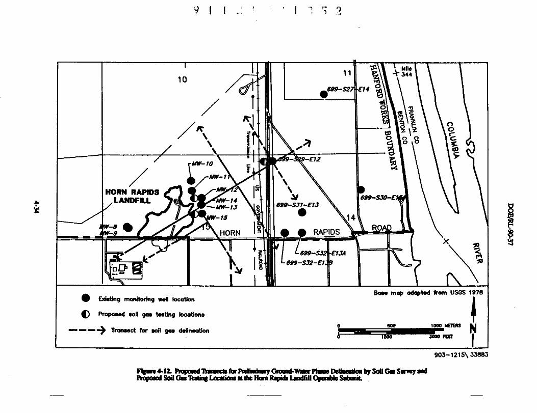
34410
Q •699-52 E1t 0
1d1/0
^,2z
0
\\ ^ ^0i
o o ;'
AM=fO9- -E12
AIN=1
HORN RAPIDSLANDFR.L -14
Alw-1J d"-sif-E1J
-fa 14
s• I^RO
HORN RAPIDS
.O^ ^' ^y I g
699- E1J1
699-SJ2-E1 ^
^ tiE l it i ll l ti^ map adopted from USGS 19788
s ng monx or ng we oca on
O Proposed sod gaa testing locations ^
Trantect for soil gas delineation o500
^^ ^s N^oao rEtr
903-1215\ 33883
FWwe 4-12. Pwpmed 1YrlaiEClt for Pjdiminrry Omomd-Wner Plme Deliaeniaa by Soii On Smvey iedPropaed Sod On 7iati3lLaceliam at the Han Rmpiib L^edfiU Opaabla Sobmit
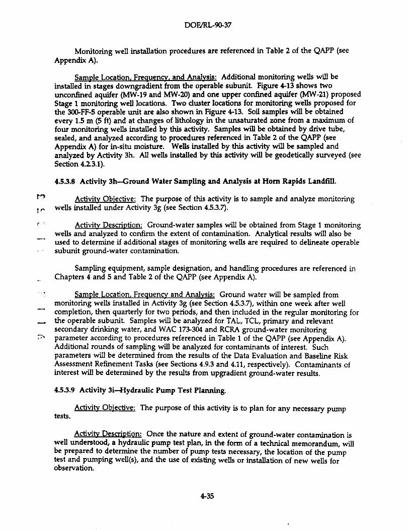
DOE/RL-90-37
Monitoring well installation procedures are referenced in Table 2 of the QAPP (see
Appendix A).
Sample Location, Frequency, and Analysis: Additional monitoring wells will beinstalled in stages downgradient from the operable subunit. Figure 4-13 shows twounconfined aquifer (MW-19 and MW-20) and one upper confined aquifer (MW-21) proposedStage 1 monitoring well locations. Two duster locations for monitoring wells proposed forthe 300-FF-5 operable unit are also shown in Figure 4-13. Soil samples will be obtainedevery 1.5 m (5 ft) and at changes of lithology in the unsaturated zone from a maximum offour monitoring wells installed by this activity. Samples will be obtained by drive tube,sealed, and analyzed according to procedures referenced in Table 2 of the QAPP (seeAppendix A) for in-situ moisture. Wells installed by this activity will be sampled andanalyzed by Activity 3h. All wells installed by this activity will be geodetically surveyed (seeSection 4.2.3.1).
4.5.3.8 Activity 3h-Ground Water Sampling and Analysis at Horn Rapids Landfill.
Activity Objective: The purpose of this activity is to sample and analyze monitoringwells installed under Activity 3g (see Section 4.5.3.7).
Activity Description: Ground-water samples will be obtained from Stage 1 monitoringwells and analyzed to confirm the extent of contamination. Analytical results will also beused to determine if additional stages of monitoring wells are required to delineate operablesubunit ground-water contamination.
Sampling equipment, sample designation, and handling procedures are referenced inChapters 4 and 5 and Table 2 of the QAPP (see Appendix A).
Sample Location, Frequency and Analysis: Ground water will be sampled frommonitoring wells installed in Activity 3g (see Section 4.5.3.7), within one week after wellcompletion, then quarterly for two periods, and then included in the regular monitoring forthe operable subunit. Samples will be analyzed for TAL, TCL, primary and relevantsecondary drinking water, and WAC 173-304 and RCRA ground-water monitoringparameter according to procedures referenced in Table 1 of the QAPP (see Appendix A).Additional rounds of sampling will be analyzed for contaminants of interest. Suchparameters will be determined from the results of the Data Evaluation and Baseline RiskAssessment Refinement Tasks (see Sections 4.9.3 and 4.11, respectively). Contaminants ofinterest will be determined by the results from upgradient ground-water results.
4.5.3.9 Activity 3i-Hydraulic Pump Test Planning.
Activity Objective: The purpose of this activity is to plan for any necessary pumptests.
Activity Description: Once the nature and extent of ground-water contamination iswell understood, a hydraulic pump test plan, in the form of a technical memorandum, willbe prepared to determine the number of pump tests necessary, the location of the pumptest and pumping well(s), and the use of existing wells or installation of new wells forobservation.
4-35
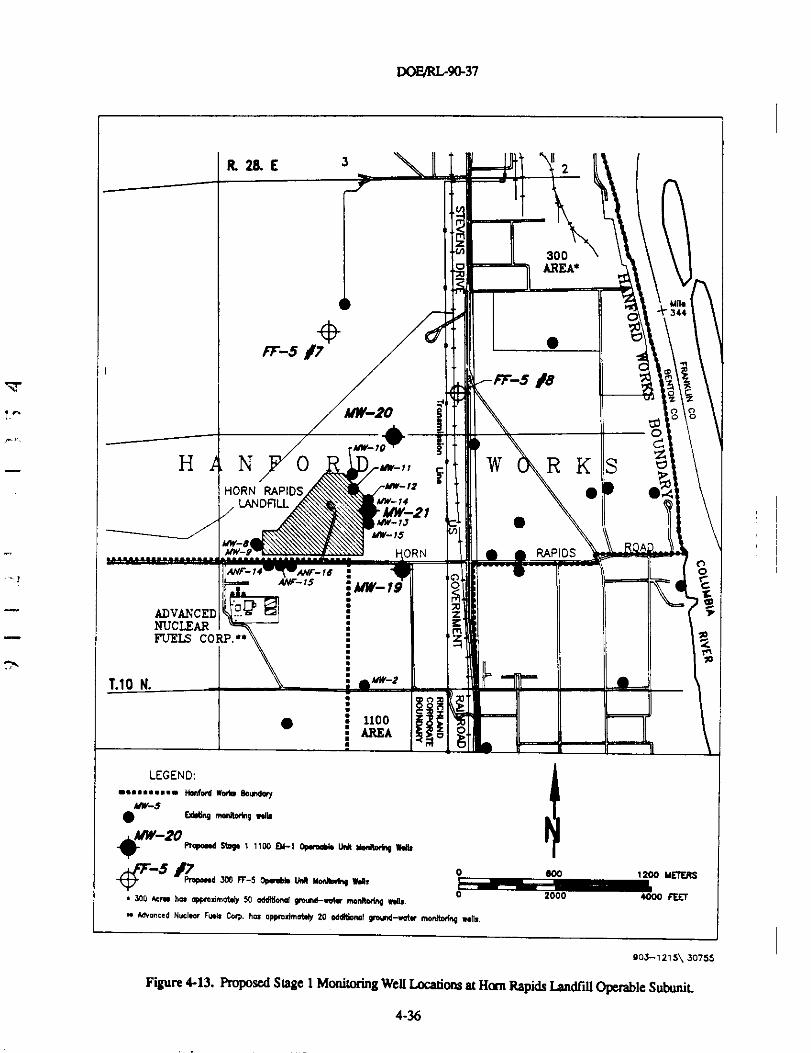
DOF/RLAO-37
•
Mw-S ORN RAPIDS
R28.E I^2
300o AREA4
Mil•344
^ d
-rF-s /7
Pr-s/eKy Z ZMf
'`v
m
O O
*MW-10
H N 0 R ,IO»=„ ^ W R K SHORN RAPIDS ^ 12
ekLANDFlLL "^''-14
A/W-?1.vw- u
IIM-!1NW-Q p
ANF-1/ .W^-76 :wr ^s cc)
^ A/W-19 o c• ^ m
ADVANCED ^NUCLEARFUELS CORP.'• z ^-
i A
Mn N. ' ""`'-?• ^^
^ ^11001 AREA
•LEGEND:
••••••.... Na.taa wen, eounanyMN=1
• Edllinp m•NloAnq .db
^^w20Ropoud Stag. 1 1100 06-1 OpweeN IMI yw" W.p.
0!00 1200 METERSs Prapa•! 300 iT-5 Opr•k^ Unl MrJbMp W.A.
"YY•300 hcr40 hea appmdmoWy 50 aAlMond qr 0 2000 4000 FEETeuM-.vlr monRainy ..Aa.
a AnranceG Nucl•cr Fwb Corp. has eppmylmol4y 20 oEAtiennl qrouq-.atr moNlMnq no,.
903-1215\ 30755
Figure 4-13. Proposed Stage 1 Monitoring We0l.ocations at Ham Rapids Landfili Operable Subunit
4-36
DOF/R1r90-37
Sample Location. Frequencv, and ++Atvsis: No sampling is required by this activity.
4.53.10 Activity 3j--Pamping Well Installation.
Activi)y Objective: If a pump test is determined to be necessary, a high capacity
pumping well will need to be installed The currently installed monitoring wells are not
capable of pumping flow rates (up to 2,500 Ymfn) large enough to adequately stress the
aquifer.
Ac6viRy DeserI on: The hydraulic pump test plan (see Activity 3f) will establish the
most effective krcation(s) for the pump test(s) and pumping well(s). The pumping wellmust be designed to accommodate and sustain large flow rates (up to 2,5001/min) with high
water transmission efficiency. Figure 4-14 illustrates the proposed construction details of
the aquifer hydraulic testing/pumping well.
Details of the pumping well installation procedures are referenced in Table 2 of theQAPP (see Appendix A).
Samvle Location. Frequencv, and n 1ypk: Soil samples will be obtained every 1.5 m
(5 ft) and at changes in lithology in the unsaturated zone at a maxdmum of four Phase II RI
well installations in the Horn Rapids Landfill vicinity. Samples will be obtained by drive
tube in accordance with procedures listed in Table 2 in the QAPP (see Appendix A). The
soil samples will be for hydrogeologic assessments and will not be chemically analyzed. All
pumping wells installed by this activity will be surveyed (see Section 4.2.3.1).
4.53.11 Activity 3k-Pump Test
Activity Objective: The purpose of conducting hydraulic pump tests, if they becomenecessary, is to obtain information on the hydraulic properties of the unconfined aquifer inthe vicinity of Horn Rapids Landf911. The infonnation obtained from the pump test will be
^ used for operable unit characterization, baseline risk assessment, and evaluation of remedialalternatives.
Activily Descriotion: Before performing drawdown/recovery tests, the wells will betested for well efficiency and antecedent trends in water levels. Well efficiency will beevaluated by using the step drawdown technique which will be conducted at threedischarge rates. Estimates of well efficiency and transmissivity will be made and theoptimal constant pumping rate for longer term drawdown/recovery test will be determined.For evaluation of antecedent trends, water levels will be monitored and recorded for aperiod of about two times the anticipated pumping time.
During the drawdown/recovery test, the well will be pumped at a constant rate for aminimum of one day. The total length of the test will be determined by a hydrogeologistand will depend on the results of the step drawdown tests. Drawdown and pumpdischarge rate will be monitored and recorded with time. The pump discharge rate will bemonitored and regulated if the discharge rate changes. After the pump is turned off, therecovery of water levels in the well will be monitored and recorded with time. Other wellsin the near vicinity, < 100 m(< 328 ft) from the pumping well, will be monitored for waterlevels during the entire test
4-37
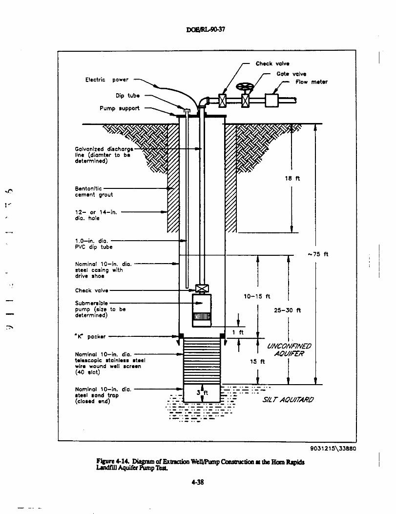
DOl'/RL9037
Electric power -
Dip tube
Pump support
Galvanized discharg,line (diomter to bedetermined)
Check valve
^ Gate valve
r- Flow meter
18 ft
Bentonitic -cement grout
12- or 14-in.dia. hole
1.0-in. dia.PVC dip tube
Nominal 10-in. dia.steel casing withdrive shoe
Check valve
Submersiblepump (size to bedetermined)
'iC packer
Nominal 10-in. dia. -telescopic stainless steelwire wound well screen(40 slot)
Nominal 10-in. dio. -steel sand trap(closed and)
-75 ft
10-15 ft I
1 25-30 ft
1 ft
t UNCONF/NEDAOU/FER
15 ft I
3IitS/LT AOU/TARD
9031215\33880
Figure 4.14. Diagnm of Extraction WeWPamp Camucuon at the Ham Rapidslmndtill Aquifer Pump Test.
4-38
DOE/RL-96a37
Details on the testing methodologies, equipment, calibration requirements, and datamonitoring and recording frequenc[es are specified in the applicable procedures referencedin Table 2 of the QAPP (see Appendix A). Procedures for handling and disposing ofpurgewater at the Hanford Site are provided in DOE-RL, Ecology, and EPA (1990).
Ss^ple Location. Freaum=. and &gjydaa The location of the test and number oftests will be determined under Activity 31(see Section 433.9).
4.53.12 Activity 31-Contaminant Degradation Evaluation.
AetiviXy Mective: The purpose of this activity is to evaluate the degradation of TCBin the ground water in the vicinity of Hom Rapids Landfill.
Activitq Desmption: Hydraulic degradation of TCE will be evaluated by collectingsamples of ground water from monitoring wells known to have detectable TCE in low,medium, and high concentrations. The ground-water samples will be analyzed for TCE andTCE degradation products at various time intervals.
Samvle Location. Frequencv. and Analvsis: Samples of ground water will be obtainedfrom MW-11, MW-12, and MW-15 and placed in volatile organic analyses (VOA) bottles.Samples will be stored in an area void of light at the average ground-water temperature forthe Horn Rapids Landfill vicinity. Samples will be extracted from the individual bottles at 1,2, 4, 8, and 12 months and analyzed for TCE and TCE degradation byproducts:dichloroethene and vinyl chloride. Analytical methods are referenced in Table 1 of theQAPP (see Appendix A).
4.6 EPHEMERAL POOL TASKS
Random surface grab samples obtained from the Ephemeral Pool during Phase I RIsampling activities found elevated PCB concentrations. Further characterization of the soilsis planned in the following task:
01 • Pedological Investigation for Ephemeral PooL
4.6.1 Task 1-Pedological Investigation for Ephemeral Pool
The pedological investigation at the Ephemeral Pool consists of one activity todelineate the PCB contamination.
4.6.1.1 Activity 1a-PCB delineation at the Ephemeral PooL
Acdvity Mective: The purpose of this activity is to delineate the lateral and verticalextent of PCB contamination within the Ephemeral PooL
Activily Descrivtion: Additional soil samples will be collected in stages to accuratelydelineate the lateral and vertical extent of PCB contamination.
4-39
DOE/RIr90-37
Surface and subsurface sampling, sampling equipment, sample handling, and sample
designation procedures are referenced in Chapters 4 and 5, and Tables 2 and 3 of the QAPP
(see Appendix A).
If a removal action Is determined to be appropriate, a new task will be created todevelop and implement a removal plan
Samvle Locations. Freque= and Ana)y,gjj: The locations of six Stage 1 surface soilsamples are shown in Figure 4-15. If additional stages of sampling are required to delineatethe lateral and vertical extent of contamination, locations will be determined upon theresults of Stage I sampling and analysis. In Stage 2, soil borings will be completed by handaugering to a depth of 1.2 m(4 ft) to determine the vertical extent Samples will becollected at depths of 0.3, 0.6, and 1.2 m (1, 2 and 4 ft) below the surface. All samplinglocations will be geodetically surveyed (see Section 4.2.3.1).
AII soil samples will be analyzed for PCBs according to the analytical proceduresreferenced in Table 1 of the QAPP (see Appendix A).
Er'
4.7 SO[TITi PIT TASKS
'- The South Pit was identified from an aerial photographic study conducted by EPA(1990) during the Phase I RI. No field investigations were conducted at this potentialoperable subunit during the Phase I RI. Due to the evidence provided by the aerialphotograph, further investigation is required. The characterization of this potentialoperable subunit is divided into three tasks:
-. , • Task 1-Contaminant Source Investigation for the South Pit• Task 2-Pedological Investigation for the South Pit
- • Task 3-Hydrogeological Investigation for the South Pit
Descriptions of these tasks are provided below.
^
4.7.1 Task 1-Contaminant Source Investigation for the South Pit
Four activities are planned for this task source data compilation, a surface radiationsurvey, a geophysical survey, and a soil gas survey.
4.7.1.1 Activity la-Source Data Compilation for the South Pit
Actift Ob' 've: The purpose of this activity is to determine if any existinginformation is available on the history of the South Pit that will determine if waste wasdisposed in the pit, and if any such disposal was related to the Hanford Site.
Activity Descrivtion: An attempt will be made to locate any existing engineeringplans or environmental reports with information on the South Pit Site visits and meetingswith former and current employees and local officials will be conducted. Evidence of thefacility being unrelated to the Hanford Site would result in the remainder of the Task 1activities, and Tasks 2 and 3, not being implemented.
4-40
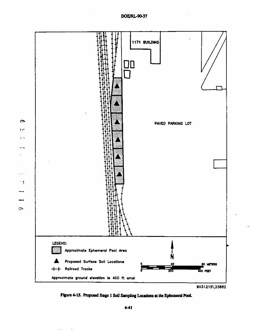
DOF/RL-9Q37
00
0
^7.
e e`
1171
PAVED PARKING LOT
LEGEND:
Q Approximate Ephemerol Pool Area
A Propossd Surtaoe Soil Locations
-F+ Railroad Tracks
No 40 so wctas
r¢r
Approximate ground elevation I. 400 ft amsl
9031215\33882
FiSare 4-1S. Proposed SnQe I So11 Smplin` I.ocadoos at dLe EpAemeral Pbd.
4-41
DOFJRLr9d37
Information collected and interviews conducted will be documented; all records soproduced shall be controlled in compliance with applicable procedures referenced in Table 2of the QAPP (see Appendix A).
SagSp +*+g Location and FreQuencv. No sampling will be required by this activity.
4.7.1.2 Activity lb-Surface Radiation Survey for the South Pit
ActiviEy Objective: The purpose of this activity is to locate any areas of radiation inthe surface soils within the South Pit
ActivityDescriDtion: An operable unit-specific background plot will first beestablished by conducting the survey on land surfaces where operable unit backgroundsoils were obtained. The surface of the operable subunit will be surveyed for alpha-, beta-,and gamma-radiation. A new activity will be created in Task 2 (Pedological Investigation) tocharacterize any surface areas identified with elevated radiation above background.
Procedures for conducting the surface radiation survey are referenced in Table 2 ofthe QAPP (see Appendix A).
^--.
Sample Locations. Freauencv and Analvjj: The background plots established for the' operable unit will be used for determining background surface radiation levels at the South
Pit This background radiation survey will be conducted in areas of the three backgroundsoil sampling locations that were established during the Phase I RI (see Figure 4-5) to thewest of the operable unit The three background plots will be approximately 23 m (75 ft) by23 m (75 ft). Sampling at the background plots will be conducted at intersecting points onapproximately an 8-m (25-ft) grid to obtain discrete readings at each point This gridspacing may be modified if it is determined that a closer spacing is required. Approximately48 total points will be sampled using this grid spacing. Such background measurementswill be obtained after the pit itself is surveyed, and only if detectable levels of radiation areencountered.
77. Sampling within the South Pit will be conducted along transects within the areashown in Figure 4-16 at approximately 8-m (15-ft) intervals to determine the location andthe extent of elevated radiation. This grid spacing may be modified if it is determined that adoser spacing is required. Where an elevated level of radiation (statistically greater thanbackground) is encountered along a tranaect, the survey will depart from the transect tolocate and quantify the source of the reading. Areas with elevated radiation will be stakedand flagged for subsequent geodetic surveying (see Section 4.2.3.1).
The surface radiation survey will be conducted for alpha-, beta-, and gamma-radiationusing a portable (vehide-mounted or hand-held) laboratory-quality alpha detector and asodium-iodide, betaJgamma detector that read in counts per minute. The survey will bedone in dry weather conditions to avoid the potential for water shielding alpha and lowerenergy beta sources.
Continuous recording equipment will be used to generate data along the grid linesduring the surface radiation survey. Records of all calibrations and procedure applicationswill be maintained in a field notebook in accordance with procedures referenced in Table 2of the QAPP (see Appendix A).
4-42
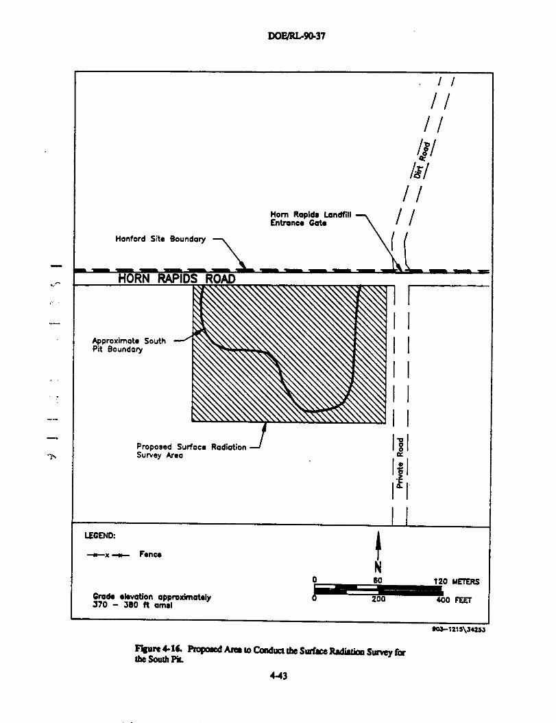
DOF/RI.9Q37
Nom Rapids LandfillEntrance Cate
Hanford Site Boundary
Approximate SouthPit Boundary
Proposed Surface RadiationSurvey Area
LEGEND:
^x^ Fence
Grade elevation approximately370 - 3e0 ft omsi
I I
I I
I I
I I
I I
ISI
I^I
I I
N0 so 120 METERS
200 {00 FEET
50a-1215\34253
the South PicPiaposed Ann to Condnct the Surfice Radiation Survey for
443
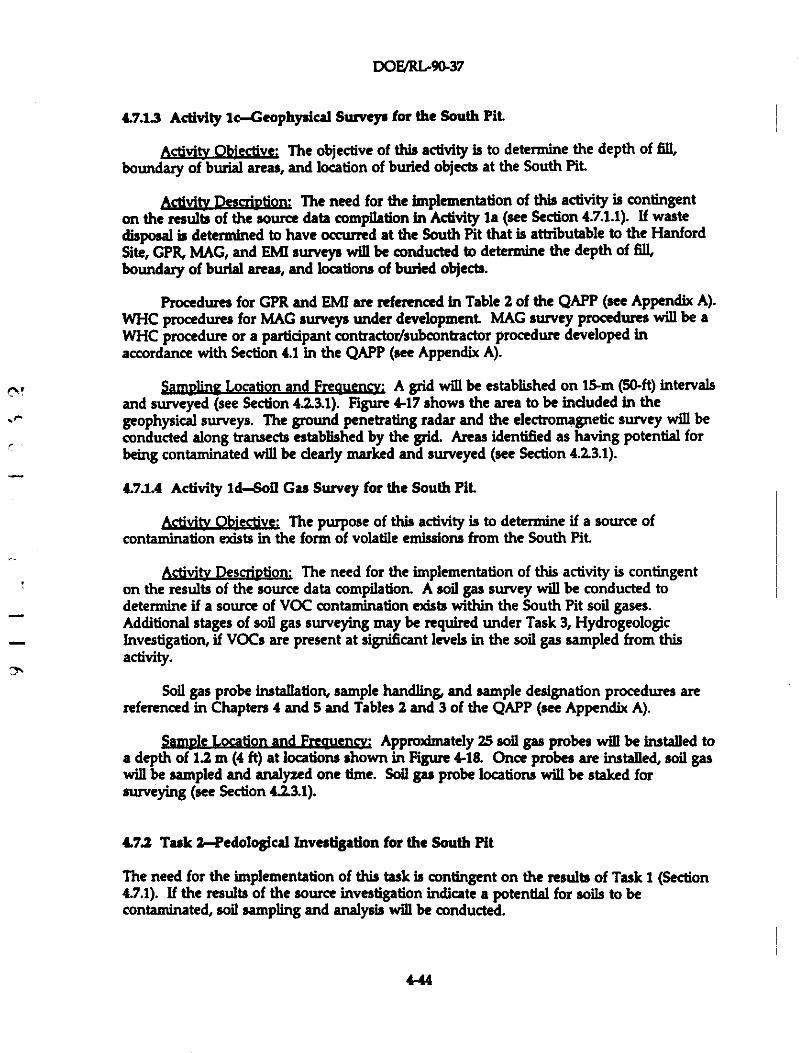
DOFJRL-90-37
4.7.1.3 Activity ic-Geophysical Surveys for the South Pit
Activity Objective: The objective of this activity is to determine the depth of fill,boundary of burial areas, and location of buried objects at the South Pit
Activi DescriDtion: The need for the implementation of this activity is contingenton the results of the source data compilation In Activity Is (see Section 4.7.1.1). If wastedisposal is determined to have occurred at the South Pit that is attributable to the HanfordSite, GPR, MAG, and BMI surveys will be conducted to determine the depth of fill,boundary of burial areas, and locations of buried objects.
Procedures for GPR and EMI are referenced in Table 2 of the QAPP (see Appendix A).WHC procedures for MAG surveys under development MAG survey procedures will be aWHC procedure or a partidpant contractor/subcontractor procedure developed inaccordance with Section 4.1 in the QAPP (see Appendix A).
SamvlinQ Location and Frequencv: A grid will be established on 15-m (50-ft) intervalsand surveyed (see Section 4.2.3.1). Figure 4-17 shows the area to be included In thegeophysical surveys. The ground penetrating radar and the electromagnetic survey will beconducted along transects established by the grid. Areas identified as having potentlal forbeing contaminated will be dearly marked and surveyed (see Section 4.2.3.1).
4.71.4 Activity id-Soil Gas Survey for the South Pit
Activity Objective: The purpose of this activity is to determine if a source ofcontamination exists in the form of volatile emissions from the South Pit
Activity Descrigtion: The need for the implementation of this activity is contingenton the results of the source data compilation. A soil gas survey will be conducted todetennine if a source of VOC contamination exists within the South Pit soil gases.Additional stages of soil gas surveying may be required under Task 3, HydrogeologicInvestigation, if VOCs are present at significant levels in the soil gas sampled from thisactivity.
Soil gas probe installation, sample handling, and sample designation procedures arereferenced in Chapters 4 and 5 and Tables 2 and 3 of the QAPP (see Appendix A).
Sample Location and Frequencv: Approximately 25 soil gas probes will be installed toa depth of 1.2 m (4 ft) at locations shown in Figure 4-18. Once probes are installed, soil gaswill be sampled and analyzed one time. Soil gas probe locations will be staked forsurveying (see Section 4.2.3.1).
4.7.2 Task 2-Pedological Investigation for the South Pit
The need for the implementation of this task is contingent on the results of Task 1(Section4.7.1). If the results of the source investigation indicate a potential for soils to becontaminated, soil sampling and analysis will be conducted.
4-14
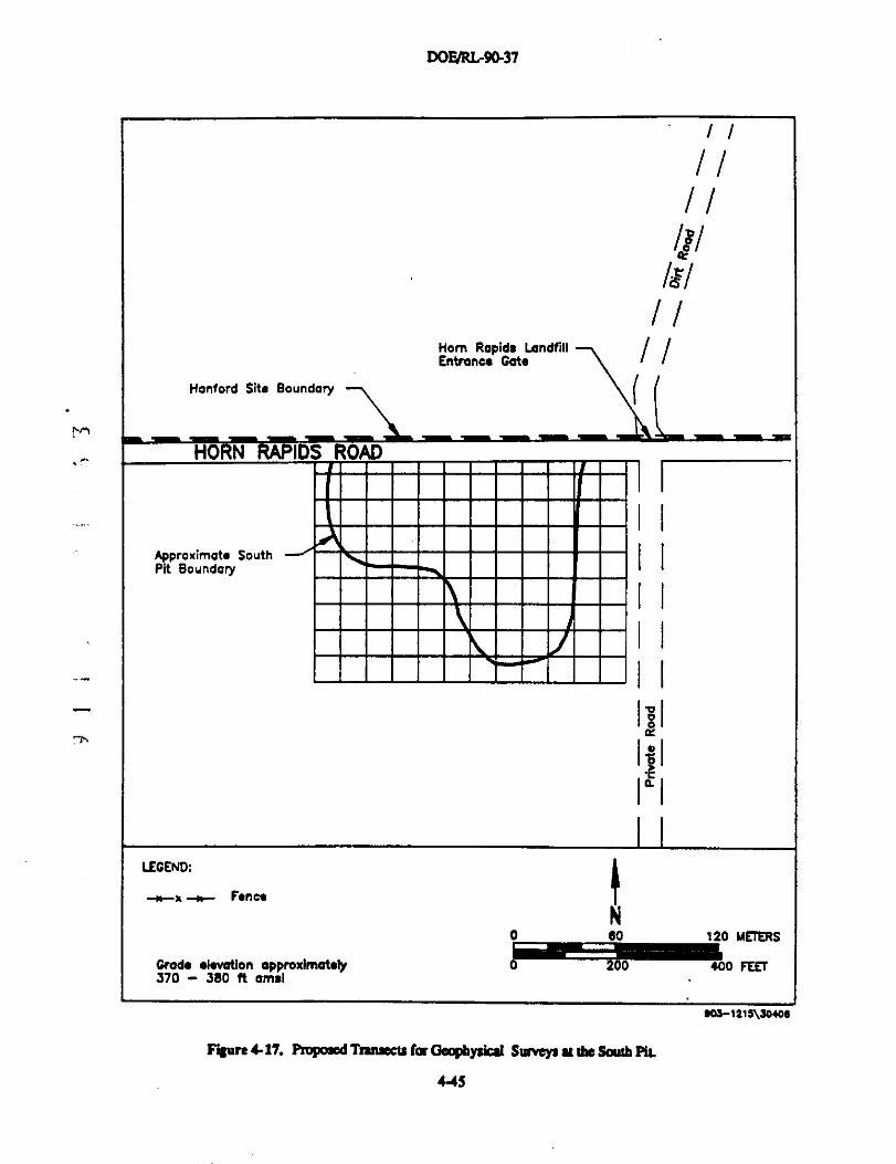
DOF/RL-9Q37
Horn Rapids LandfillEntrance Gate
Hanford Site Boundary
Nn
,r
'n
Approximate SouthPit Boundary
LEGEND:
--w-a --w-- Fence
Grade elevation approximately370 - 360 ft amsl
1^-IIil
I
I
I I
aol
^I
lal
^
N0 60 120 METERS
♦00 FEET
Fisun 1-17. Pmpoaed Tianseeu for Geophysical Smvays at tlie South PIL
"S
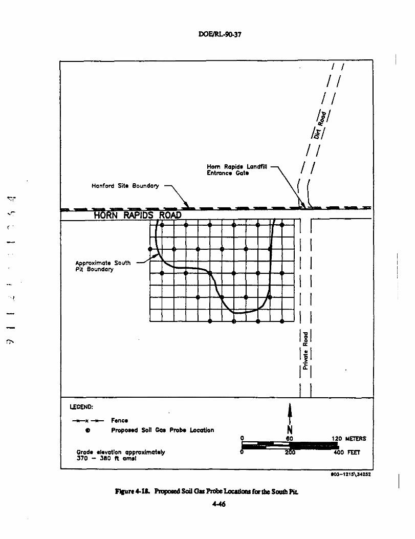
DOF/RL-90-37
Hom Rapids LandfillEntnance Gate
Hanford Site Boundary
IMy
1
f
Approximata SouthPit Boundary
IEGEND:
-«--x -+r- Fence
O Proposed Soil Gas Probe Location
Grade elevation opproximately370 - 380 ft amsl
Il
AF/
l^-1 I
I I
I I
I I
I I
Ibl
I^I
lal
IN
0 80 120 METERS
^^0 FEEi
e03-1216\74252
FiSare 4-ld. Pmpomd Soil Gs Probe Laadan: for the Sowb Pit
4-46
DOE/R1.90-37
4.7.21 Activity 2a-" Sampling and Analysis at the South Pit
Activi , Obiective: The purpose of this activity is to determine if any contaminationis present in South Pit soils and, if required, to delineate the lateral and vertical extent
&q&b* QLjgption: This activity will be conducted in stages. During Stage 1,surface and subsurface soil samples will be collected and analyzed to characterizecontamination in soils at the South Pit During Stage ?„ surface and subsurface soils will becollected to determine the extent of contamination If required by Stage 1 sampling andanalysis.
Surface and subsurface sampling, sampling equipment, sample handling, and sampledesignation procedures are referenced in Chapters 4 and 5 and Table 2 of the QAPP (seeAppendix A).
Sample Location. Freauencv, and Anal,yis: The Stage 1 soil sample locations will bedetermined by the results of the activities in Task 1(Section 4.8.1). Stage 1 soil samples willbe analyzed for TAL and TCI. parameters. Stage 2 sampling locations will be determinedupon results of Stage 1 sampling and analysis. Stage 2 samples will be analyzed forcontaminants of interest Such parameters will be determined from the results of the DataEvaluation and Baseline Risk Assessment Refinement Tasks (see Sections 4.9.2 and 4.11,respectively). Analytical procedures are referenced in Table 1 of the QAPP (seeAppendix A).
4.73 Task 3-Hydrogeological Investigation for the South Pit
The need for the implementation of this task is contingent on the results of Task Iand Task 2. If further hydrogeological investigation is required, the Horn Rapids Landfillhydrogeological investigation will be expanded to include the South Pit due to its dose
_ proximity.
,-,4.8 TREATABII.TTY STUDY TASKS
Some of the technologies selected for detailed analysis at the 1100-EM-1 operable unitin the Phase III FS may be sufficiently developed, proven, and documented such thatunit-specific characterization collected during the Phase 11 RI is adequate for evaluationwithout conducting treatability testing. However, some technologies may not besufficiently demonstrated to predict treatment performance or to estimate the size and costof treatment units. Some treatment processes, particularly innovative technologies, are notsufficiently understood for performance to be predicted, even with a completecharacterization of the wastes.
When treatment performance is difficult to predict, actual testing of the process, oneither a bench scale or pilot scale, may provide the most cost-effective means of obtainingthe necessary performance data. At the Hanford Site, some treatability investigations maybe performed on a Site-wide basis, rather than on an operable unit-specific basis. Any suchSite-wide treatability investigation results relevant to 1100-EM-i that are completed in time
4-47
DoF/Ri<9as7
to be applied to the operable unit will be Incorporated into the project through the normal
FS technology implementability evaluation processes.
The primary purpose of the treatability investigation is to provide sufficienttechnology performance infonaation and to reduce cost and performance uncertainties toacceptable levels, so that treatment altematives can be fully developed and evaluated duringthe Phase III FS. Secondarily, the treatability investtgation may generate Information usefulin conducting the detailed design of a treatment remedy, If the particular technologyinvestigated Is a component of the alternative selected to be the remedial action for1104EM-1. The allocation of time for a potential treatability investigation also provides amechanism through which to conduct further operable unit characterization activities in theevent that the need for such activities is identified.
If and when the need arises to Implement a treatability investigation, this portion ofthe work plan will be expanded by amendment to provide such details of the Phase II RIactivities.
4.8.1 Task 1-Treatability Investigation Work Plan Development
Treatability testing to support the Phase III FS can be performed by using either-- bench-scale or pilot-scale studies. An appropriate work plan for such studies will be
developed. If necessary, a literature survey supplementing those conducted during theinitial phases of the FS will be undertaken to Identify specific data needs for the treatabilityinvestigation.
° The survey will have the following objectives:
• Determine if the performances of treatment technologies under consideration. have been suffidently documented on similar wastes, taking into consideration
the scale of such documentation (e.g., bench, pilot, or full-scale)
^ • Determine the number of times the treatment technologies have beensuccessfully used
• Gather infonration on relative costs, applicability, removal efficiencies,operations and maintenance requirements, and implementability of thecandidate treatment technologies
• Determine specific testing requirements and appropriate scale for any requiredtreatability tests.
Any treatability studies will include the following steps:
• Preparation, review, and approval of a treatability investigation work plan forthe bench-scale or pilot-scale studies
• Performance of the bench-scale or pilot-scale testing
• Evaluation of data from bench-scale or pilot-scale testing
4-48
DoEJRL9a37
• Incorporation of the results of the testing into the final RI report
Bench-acale (laboratory) testing may be used to provide information to determine thefeasibility of waste treatment or destruction technologies, although cue must be taken inextrapolating laboratory data to full-scale perfornunce. Bench-acale tests can be used toevaluate a wide variety of operating conditions and to determine broad operating conditionsto allow optimization during additional bench- or pilot-scale tests. Bench-scale testing isusually a fast and low-cost process, relative to pilot-scale testing.
Potential objectives of bench-acale testing are to determine the following:
• The effectiveness of the treatment technology on the 1100-EM-1 wastes
• The differences in performance between competing manufacturers
• The differences in performance between alternative chemicals used in theP^ treatment process
• The sizing requirements for any pilot-scale studies
• The potential technologies to be pilot tested
• Sizing of those treatment units that would affect the cost of the technologysufficiently to affect the remedial action alternatives analysis process (Phase IIIFS)
• Compatibility of process materials with the operable unit wastes.
Before bench-scale treatability tests are initiated, the following information will becollected or developed:
-^ • Test procedures
n A waste sampling plan
• Waste characterization infonmation (Phase I RI data)
• Treatment goals (will be available, or can be derived, from corrective actionobjectives defined and refined during the initiai phases of the FS)
• Data requirements for estimating the technology cost within -30% to +50%accuracy
• Required test services, equipment, chemicals, and analytical services.
For a technology that is well developed and tested, bench-scale studies are usuallysufficient to evaluate performance on new wastes. For innovative technologies, however,pilot-scale tests may be required because necessary to conduct full-scale tests iseither limited or nonedstent
449
DOEJRL-9437
A pilot-scale test, as compared to a bench-scale test, is intended to more accuratelysimulate the operations of a full-scale process. However, pllot-scale tests require significanttime and can be quite costly. Therefore, the need for pilot-scale testing must be determinedby comparing the potential for improved performance or savings in time or money duringremedial action implementation against the additional time and expense needed for the testPflot-scale testing is often appropriate for innovative technologies, and such testmg will beconsidered if it offers the potential for more permanent waste treatment or destruction, orthe potential for signifieant savings in time or money required for a remedial action toachieve remedial action objectives.
Before the initiation of any pilot-scale testing, the following information, in additionto the items mentioned above with regard to bench-scale testing, will be collected ordeveloped:
• Unit-specific information impacting test requirements (waste characteristics,facility characteristics, and availability of services and equipment)
• Waste requirements for testing (volumes, need for any pretreatment, handling,transport, and disposal)
• Specific data requirements for technologies to be tested.
Two important considerations in developing each individual work plan are where andby whom the tests will be conducted. If the test is to be conducted offsite or at the 1100Area, special permits may be necessary for either constructing and operating equipment ortransporting wastes and residues offsite. Similarly, if the work is conducted by asubcontractor, equipment, test, and sample analyses will need to be negotiated with respectto the treatability investigation work plan.
° Quality assurance/quality control plans will be reviewed to determine any special_ quality-related requirements necessary for each individual treatability investigation. Special
consideration will be given to the ability to detect and reliably measure contaminants at the7% concentrations required by the criteria, as well as the potential for contamination of samples
during collection, storage, and analysis.
Health and safety plans will be reviewed to determine whether any special trainingor procedures will be needed. Health and safety considerations will be given to both waste-handling and test operations.
Recommended formats for bench-scale and pIIot-scale treatability investigation workplans, along with further details on the process, can be found in EPA's RJ/FS interim finalguidance (EPA 1988).
4.8.2 Task 2-Treatability Investigation Implementation
This task is reserved for the actual implementation of any treatability investigation.The results of this task will be integrated into the site characterization summary to createthe final Phase II RI report.
4-50
DoFJRL-90-37
4.9 DATA EVALUATION TASKS
Data generated during the Phase II RI will be evaluated in an ongoing manner Inorder to allow dedsions to be made regarding further characterization of the operable unitThe results of these evaluations will be incorporated into the monthly progress reports tomake them available to project decision makers.
Data evaluation will be undertaken in tasks corresponding to the varioussubcomponent investigationa:
• Contan3nant source data evaluation• Pedological data evaluation• Hydrogeologic data evaluation• Ecological data evaluation.
49.1 Task 1-Contaminant Source Data
Information compiled under the source data wmplation activity at the South Pit willbe used to determine the past operations, occurrence of waste disposal, and typea of wastedisposed of at the pit and if such disposal is related to the Hanford Site. Geophysicalsurvey results from the South Pit will be used to determine the boundaries, depth of fill,and locations of waste disposed of in the pit Results from additional geophysical surveysconducted at Hom Rapids Landfill will be used to determine the presence of 10 or more 55gallon drums.
Soil gas will be used at UN-1100-6 to determine if a source of the low levels of VOCsfound in the surface soils is present in the vadose zone or ground water. The quarterlyresults from permanent soil gas monitoring at the Horn Rapids Landfill will be used todetermine if a rupture has occuried in a suspected buried dnum of liquid solvent A soil gas
' survey will also be conducted at the South Pit to detenaine if a soura of VOCs is present^ in soil gas at the pit
eN A surface radiation survey at the UN-1100-6 will be used to determine if the surfacesoils of the operable subunit are contaminated with radioactivity. A surface radiationsurvey will also be conducted at the South Pit for health and safety. The results of thesurveys will be compared to background to determine if there is an elevated level ofradiation attributable to these facilities. Statistically significant levels will be determined byelevated levels above the 0.95/0.95 upper tolerance limits of the background distribution (seeSection 12 in the QAPP, Appendix A).
4.9.2 Task 2-Pedologieal Data
Results of soil sampling will be plotted to reveal the lateral and vertical distributionsof PCB at the Horn Rapids Landfill and the Ephemeral Poot Soil sampling may beconducted at the South Pit to determine if soils are contaminated at the pit. Ifcontamination is present in the soils at the South Pit the results will be plotted to determinethe lateral and vertical distributions. The soil sampling results will be compared tobackground to detennine If there are elevated levels of contaminants attributable to Horn
4-51
DOFJRL90-37
Rapids Landfill, and the South Pit Statistically significant levels will be determined byelevated levels above the 0.95/0.95 upper tolerance limits of the background distribution (seeSection 12 in the QAPP, Appendix A). Data will be used in baaeline risk assessmentrefinement
4.9.3 Task 3-Hydrogeologic Data
The ground-water sampling results will be compared to background to determine ifthere are elevated levels of contaminants attributable to the 1100-2 operable subunitStatistically significant levels will be determined by elevated levels above the uppertolerance limits of the backggound distribution (see Section 12 in the QAPP, Appendix A). Itis important to note, that ground-water flow data will be used in conjunction withstatistical data to evaluate ground-water contamination. Data will be used in baseline riskassessment refinement
^ Results from monitoring wells upgradient to the Horn Rapids Landfill will be used to^ evaluate encroaching contaminant plumes. Soil gas results from Horn Rapids Landfill will
be evaluated to assist in placement of ground-water monitoring wells. Results ofdowngradient monitoring wells will be used to determine the extent of contamination inground water that is attributable to the landfilL Statistically significant levels will be
° determined by elevated levels above the 0.95M.95 upper tolerance limits of the backgrounddistribution (see Section 12 in the QAPP, Appendix A). It is important to note that ground-water flow data will be used in conjunction with statistical data to evaluate ground-watercontamination. Data will be used in baseline risk assessment refinement Aquifer test datawill be evaluated for modeling ground-water characteristics.
The results of the operable-unit-wide ground-water monitoring interim report will beused to refine the list of contaminants of potential concern. Ground-water potentiometricmaps for the 1100 and 300 Areas will be used to observe fluctuations over the time period ofsampiing.
4.9.4 Task 4-Ecological Data
Data will be evaluated and used to refine RI base maps. Future land- and water-useprojections and ground-water receptor point data will be used in refining the baseline riskassessment
4.10 VERIFICATION OF CONTAMIIIANT- AND LOCATION-SPECIFIC LEGALLYAPPLICABLE OR RELEVANT AND APPROPRIATE ENVIRONMENTALSTANDARDS, REQUIREMENTS, CRITERIA, AND LII4STTATIONS TASK
This task will have EPA and Ecology verify the potential contaminant- and k>cation-spedfic ARARs for the contamination attributed to the operable unit Remedial actionobjectives for BEHP and PCB, based upon such considerations, were proposed in the PhaseI RI Report (DOE-RL 1990). The report gave no indication of the applicability of anylocation specific ARARa to 1100-EM-1. Any new regulations enacted or amended since the
4-52
DoF/RLr9487
Phase I RI will be evaluated. Project staff will work with the regulatory agendes and,taking unit-specific conditions into account, will dedde which promulgated environmentalstandards, requirements, criteria, and tfmitations are applicable or relevant and appropriateto 110QEM-1.
4.11 BASELINE RISK ASSESSMENT REFIIVEMENT TASKS
The purpose of these tasks is to refine the baseline risk assessment contained in thePhase I RI report (DOE-RL 1990). The baseline risk assessment provides an evaluation ofthe potential threats to human health and the environment in the absence of any remedialaction. It will provide the basis for determining whether or not remedial action is necessaryand the justification for determining dean-up levels. The Phase I RI risk assessment wasdeveloped according to EPA (1989) and EPA Region X (1990). Further refinement will beconducted according to the following tasks:
• Contaminant identification-' • Exposure assessment^ • Toxicity assessment
• Risk characterization.
4.11.1 Task 1-Contaminant Identification
This task will modify the list of contaminants identified in Phase I as Phase II RI dataare screened to determine the nature and extent of contamination and to identify targetsubstances for the risk assessment Target substances are selected on the basis of intrinsictoxicological properties, waste volumes, and environmental occurrence.
4.11.2 Task 2-Exposure Assessment Refinement
" This task will evaluate exposure pathways to better characterize the potentiallyexposed receptor (human and environmental) populations and to refine the extent of anyexposure determined in the Phase I RI report (DOE-RL 1990). Future land- and water-useprojection data (see Section 42.1.1) will be used to enhance the analyses of exposures thatmay occur in the future if no remedial action is undertaken.
The final step will be to revise the qualitative or quantitative estimate of totalexposure levels for each receptor popuiation based on refined exposure assessmentinformation. .
4.113 Task 3-Toxidty Assessment Refinement
This task will modify the toxicity assessment prepared during Phase I RI and used toassess the risks associated with releases of contaminants. Tmddty Information will beupdated to reflect revised values for skipe factors and reference doses, and to evaluate anyadditional target substances identified during the Phase II RI.
4-53
DOE/RL-90-37
4.11.4 Task 4-Risk Characterization Refinement
This task will modify the Phase I risk characterization contained in the Phase I RI
report (DOE-RL 1990). The refined risk characterization will be based on additional
contaminant identification, exposure assessment information, and toxddty assessment data.
A comparison will be performed between risks associated with actual contaminant levels
identi6ed in the exposure assessment and acceptable levels of contamination. Contaminant-
specific ARARs, when available, will be used to determine the acceptable levels. When
ARARs are not available, acceptable levels will be based on environmental concentrations
that will yield exposures no greater than (Note: the implementation of Section 4.10 may
result in a slight modification of these aiterla):
• The reference dose, for non-cardnogens• A 1E-06 to IE-04 excess lifetime cancer risk, for carcinogens.
Priority will be given to the acceptable environmental concentrations thus determined
in establishing contaminant-spedfic clean-up levels for the final remedial action.
4.12 PHASE II REMEDIAL INVESTIGATION REPORT TASK
A fina11100-EM-1 Operable Unit RI report will be prepared at the end of Phase II RI
activities.
4-54
DOE/RL-96-37
5.0 SCHEDULE
The anticipated schedule for completing the RI/pS for the 1100-EM-1 Operable Unit ispresented in Figure 5-1. This schedule is based on a staged approach as detailed in the taskdescriptions In Chapter 1 It is subject to modification as data are collected and evaluated,and the operable unit becomes better characterized. Directed actions by EPA may requirere-deftnition of tasks in the work plan which may effed the scheduk. The staged approachis utilized because it Is cost effective and the Phase I RI did not indicate the edstence of anyimminent and substantial endangerment to human health or the environment Theassumptions for this schedule are based on best engineering judgement
Major assumptions that were used in developing this schedule indude:
• One Stage 1 monitoring well, and two Stage 2 monitoring wells are installedat 1100-2 operable subunit
^' • The UN-1100-6 operable subunit is not a source of TCA contamination^
• Upper confined aquifers are not impacted at any operable subunit
^ • Eight to ten Stage 1 downgradient monitoring wells, and two upgradientmonitoring wells are installed at Horn Rapids Landfill
• Two stages of soil sampling are required to delineate the PCB contaminationin soils at the Horn Rapids Landfill
• One stage of EPA-directed subsurface soil sampling is planned at Horn RapidsLandfill
" • Three drill rigs are available at all times, and three weeks are required to_ complete the installation of a monitoring well per drill rig
^^ • Two stages of soil sampling are required to delineate the PCB contaminationat the Ephemeral Pool
• Phase II RI Report will be based on two confirming rounds of ground-watermonitoring
• Two and one-half months are required, after receipt of the last portion ofvalidated field and analytical data, to produce a preliminary draft Phase II RIReport for review.
5-1
DOFJRL-9437
This page left intentlonally blank
^
N
5-2
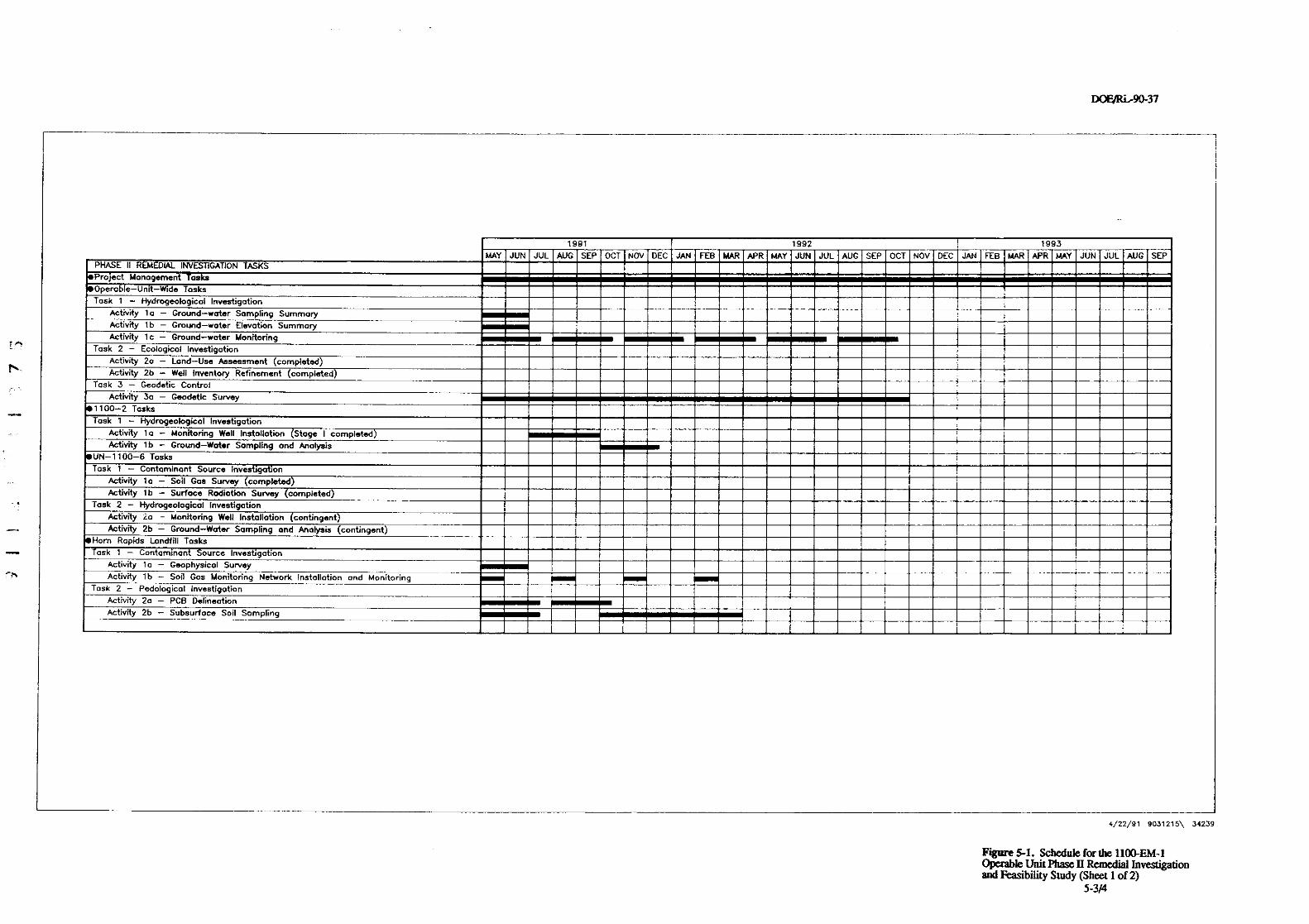
DOFJRi-90-37
.r.,
1991 1992 1993
MAY JUN JUL AUG SEP OCT NOV DEC JAN FEB MAR APR MAY JUN JUL AUG SEP OCT NOV DEC JAtJ FEB MAR APR MAY JUN JUl AUG SEPPHASE II REMEDIAL INVESTIGATION TASKSProject Management Tasks
Operable-Unit-Wide Tasks
Task 1 - Hydrogeological Investigation
Activity to - Ground-water Sampling Summary
Activity lb - Ground-wcter Elevation Summary
Activity 1 c - Ground-water MonitoringTask 2 - Ecological Investigation
Activity 2o - Lond-Use Assessment ( completed)
Activity 2b - Well Inventory Refinement (completed)
Task 3 - Geodetic Control
Activity 3a - Geodetic Survey
1100-2 Tasks
Task 1 - Hydrogeologicol Investigation
Activity 1a - Monitoring Well Installation (Stage I completed)
Activity lb - Ground-Water Sampling and Analysis
UN-1100-6 Tasks
Task 1 - Contaminant Source Investigation
Activity la - Soil Gas Survey (completed )Activity lb - Surface Radiation Survey (completed)
Task 2 - Hydrogeological Investigation
Activity ia - Monitoring Well Installation (contingent)
Activity 2b - Ground-Water Sampling and Analysis (contingent)
Hom Rapids Landfill Tasks
Task 1 - Contaminant Source Investigation
Activity 1 a - Geophysical Survey
Activity lb - Soil Gas Monitoring Network Installation and Monitoring
Task 2 - Pedalogical Investigation
Activity 2a - PCB Delineation
Activity 2b - Subsurface Soil Sampling
4/22/91 9031215\ 34239
Figure 5-1. Schedule for the 110(LEM-1Operable Unit Phace II Remedial lnvestigationand Feasibility Study (Sheet 1 of 2)
5-3/4
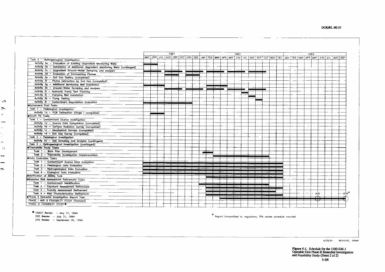
DOF/RL-90-37
N-
e?%
-- 1991 1992 7993MAY JUN JUL AUG SEP OCT NOV DEC JAN FEB MAR APR MAY JUN JUL AUG SEP OCT NOV DEC JAN FEB MAR APR MAY JUN JUL AUG SEP
Task 3 - Hydrogeolagicol Investigation
Activity 3a - Evaluation of Existing Upgrodient Monitoring Wells
. , ^
Activity 3b - Installation of Additional Upgrodient Monitoring Wells (contingent)Activity 3c - Upgradient Ground-Water Sampling and Analysis
Activity 3d - Evaluation of Encroaching PlumesActivity 3e - Soil Gas Testing (completed)
Activity 3f - Plume Delineation by Soil Gas (completed)
Activity 3g - Additional Monitoring Well Installation
Activity 3h - Ground-WOter Sampling and Analysis
Activity 3i - Hydraulic Pump Test Planning
Acti.ity 3j - Pumping Well Installation
Act'rvity 31, - Pump Testing
ActivRy 31 - Contaminant Degradation Evoluation6Ephemeral Pool Tasks
Task 1 - Pedological Investigation
Activity ia - PCB Delineotion (Stoga I completed)
•South Pit Tasks
Task 1- Contaminant Source Investigation
Activity ta - Source Data Compilation ( completed)
Activity lb - Surface Radiation Survey ( completed)
Activity To - Geophysical Surveys ( completed)
Activity td - Soil Gw Survey ( completad)Task 2 - Pedologiaal Inveatigotion
Activity 2a - Soil Sampling and Analysis (contingent)Task 3 - Hydrogeological Investigation (contingent)
*Treatobility Study Tosks
Task 1 - Work Plan Development
Task 2 - Treatability Investigation Implementation•Data Evaluation Tosks
Tosk 1 - Contominant Source Dota EvoluotionTask 2 - Pedologicol Data Evaluation
Task 3 - Hydrogeological Data Evaluation
Task 4 - Ecological Data Evaluation*Verificotion of ARARs Task
B li iase ne R• sk Assessment Refinement Tasks
Task 1 - Contominant Identification
Task 2 - Exposure Assessment Refinement
Task 3 - Toxicity Assessment Refinement
aek 4 - Risk Choracterizotion Refinement DOE EP*Phose II Remedial Investigation Repcrt Task
PHASE I AND 11 FEASIBILITY STUDY finolized) iPHASE III FEASIBILJTY STUDYO I
® USACE Review - May 31, 1994
DOE Review - July 31, 1994
EPA Review - September 30, 1994
*Report transmitted to regulotors; TPA review schedule enacted
\'k
/
4/23/91 9031215\ 34240
Figure 5-1. Schodule for the 1100-EM-1Operable Unit Phaee 11 Remedial Investigationand Feasibility Study (Sheet 2 of 2)
5-5l6
DOE/RIr9437
6.0
DOE-RL, 1990, Phase I Remedial Investigation Report for the Hanford Site 1100-EM-1Operable Unit, DOE-RL 90-18, U.S. Department of Energy, Richland Operations Office,Richland, Washingtoa
DOE-RL,1989, Remafial Inotstigation/FeatNity Study Work Plan for the 1100-EM-1 OperableUnit Hanford Site, Richland, Washington. DOWRL 88-23, U.S. Department of Energy,Richland Operations Office, Richland, Washington.
DOE-Ri., Ecology and EPA, 1990, Strategy for Handling and Dispasing of Purgeuxiter at theHanford Site, Washington, U.S. Department of Energy, Richland Operations Office,Richland, Washington, Washington State Department of Ecology, Olympia,Washington, and U.S. Environmental Protection Agency, Richland, Washington.
Ecology, EPA and DOE-RL, 1990a, Hanford Federal Facility Agreement and Consent Order,Washington State Department of Ecology, Olympia, Washington, U.S. Environmental
S^ Protection Agency, Region X, Seattle, Washington, and U.S. Department of Energy,Richland Operations Office, Richland, Washington
_ Ecology, EPA and DOE-RL, 1990b, Community Relations Plan for the Hanford Federal FacilityAgreement and Consent Order, Washington State Department of Ecology, Olympia,Washington, U.S. Environmental Protection Agency, Seattle, Washington and U.S.Department of Energy Richland Operations Office, Richland, Washington.
EPA, 1990, Aerial Photographic Analysis of Rockuxll Hanford Operations Area 1100 NW:Richland, Washington, TS-PIC-90754, U.S. Environmental Protection Agency,Environmental Monitoring Systems Laboratory, Las Vegas, Nevada.
° EPA, 1989, Risk Assessment Guidence for Superfund Volume 1: Human Health Evaluation Manual;_ Interim Final, OSWER 92B5.7-01a, U.S. Environmental Protection Agency, office of
Emergency and Remedial Response, Washington, D.C.rr
EPA, 1988, Guidance for Conducting Remedial Investigations and Feasibility Studies UnderCERCI.A: Interim Final, EPA/54Q/G-89/004, OSWER Directive 9355.3-01, U.S.Environmental Protection Agency, Office of Emergency and Remedial Response,Washington, D.C.
EPA, 1987a, Data Quality Objectiaes for Remedial Response Actiaities: Development Process,EPAr>M-87/003, OSWER Directive 9355.47B, U.S. Environmental Protection Agency,Washington, D.C.
EPA,1987b, Data Quality Objectiaes for Remedial Response Actiaitiex Example Saenario: RI/FSActivities at a Site with Contaminated Soils and Ground Water, EPA/50G-87/004, OSWERDirective 9355.478, U.S. Environmental Protection Agency, Washington, D.C.
EPA-Region X, 1990, Exposure Parameters, United States Environmental Protection Agency,Region X, Seattle, Washington.
6-1
DOE/RL-9a37
McCain, R.G. and W.L. Johnson, 1990, A Proposed Data Quality Strategy for Hanford SiteCharacteriration, WHC-SD-EN-AP-023, Westinghouse Hanford Company, Ricliland,Washington.
Runchal, A. and B. Sagar,1990, PORFLOW: A Model for Fluid Flow, Heat and Mass Tmnsport:MulhJluid, Multiphase Fractured or Porous Media: User's Manual, Version 210, Analyticaland Computational Research, Inc., West L= Angeles, California.
USGS,1978, Rfdi/andti Washington, Topographic map, Scale 1:24,000, U.S. Geological Survey,Denver, Colorado.
WHC, 1990, Industrial Safety Manual, WHC-CM4-3, Vol. 1-3, Westinghouse HanfordCompany, Richland, Washington
r ^N
6-2
APPENDDC A
QUALITY ASSURANCE PROJBCT PLAN
cs^
^
DOFJRL-9Q37
This page intentionally left blank
c"I
T
A-ii
DOF/RL-9a37
GLOSSARY
AccurM: Accuracy may be interpreted as the measure of the bias in a system. Sampling
accuracy is normally assessed through the evaluation of matrix spiked samples andreference samples.
&& Audits in environmental investigations are considered to be systematic checks toverify the quality of operation of one or more elements of the total measurement system.In this sense, audits may be of two'types: (1) performance audits, in which quantitativedata are Independently obtained for comparison with data routinely obtained in a mea-surement system, or (2) system audits, invoh+ing a qualitative onsite evaluation oflaboratories or other organizational elements of the measurement system for compliancewith established quality assurance program and procedure requirements.
Blind samvle : A blind sample refers to any type of sample routed to the primary laboratoryfor purposes of auditing performance relative to a particular sample matrix and analytical
- method. Blind samples are not specifically identified as such to the laboratory; they may bemade from traceable standards or may consist of sample material spiked with a knownconcentration of a known compound.
Comparabili : Comparability is an expression of the relative confidence with which onedata set may be compared with another.
Completeness : Completeness is the measure of the amount of valid data actually obtainedagainst the amount expected under normal correct conditions.
Confidence interval : Confidence intervals are applied to bound the value of a populationparameter within a specified degree of confidence (i.e., the confidence coefficient), usually90%, 95%, or 99%. The form of a confidence interval depends on the underlyingassumptions and intentions. It assumes different values for different random samples andrequires specification of the number of observations on which the interval is based.
Ueviation : For the purpose of environmental investigations, deviation refers to a planneddeparture from established criteria that may be required as a result of unforeseen fieldsituations or that may be required to correct ambiguities in procedures that may arise inpractical applications.
$quivment blanks : Equipment blanks consist of organic-free deionized, distilled waterwashed through decontaminated sampling equipment and placed in containers identical tothose used for actual field samples; they are used to verify the adequacy of samplingequipment decontamination procedures and are normally collected at the same frequenry asfield duplicate samples.
Field blanks : Field blanks consist of organic-free deionized, distilled water, transferred to asample container at the site and preserved with the reagent specified for the analytes ofinterest; they are used to check for possible oontamination originating with the reagent orthe sampling environment and are normally collected at the same frequency as fieldduplicate samples.
A-iii
DOF/RLr9Q37
Field duplicate samvle : Field duplicate samples are samples retrieved from the same
sampling location using the same equipment and sampling technique, placed in separate
identically prepared and preserved containers, and analyzed independently. Field duplicate
samples are generally used to verify the repeatability or reprodudbility of analytical data
and are normally analyzed with each analytical batch or every 20 samples, whichever is
greater.
Matrix spiked samvles : Matrix spiked samples are a type of laboratory quality control
sample; they are prepared by splitting a sample received from the field into two
homogenous aliquots (i.e., replicate samples) and adding a known quantity of arepresentative analyte of interest to one allquot to calculate percentage of recovery.
Nonconformance : A nonconformance is a deficiency in characteristic, documentation, or
procedure that renders the quality of material, equipment, services, or activitiesunacceptable or indeterminate. When the defidenry is of a minor nature, does not effect apermanent or significant change in quality if it is not corrected, and can be brought intoconformance with immediate corrective action, it shall not be categorized as anonconformance. However, if the nature of the condition is such that it cannot be
c° immediately and satisfactorily corrected, it shall be documented in compliance withapproved procedures and brought to the attention of management for disposition andappropriate corrective action.
Precision : Precision is a measure of the repeatability or reproducibility of specificmeasurements under a given set of conditions. Spedfically, it is a quantitative measure ofthe variability of a group of measurements compared to their average value. Precision isnormally expressed in terms of standard deviation, but may also be expressed as thecoefficient of variation ('i.e., relative standard deviation) and range (i.e., maximum valueminus minimum value). Precision is assessed by means of duplicate/replicate sampleanalysis.
Ouality assurance : Quality assurance refers to the total integrated quality planning, quality_ control, quality assessment, and corrective action activities that collectively ensure that the
data from monitoring and analysis meet all end user requirements and/or the intended enduse of the data.
Ouality Assurance Program Plan : The Quality Assurance program plan is an orderlyassemblage of management policies, objectives, principles, and general procedures by whichan agency or laboratory outlines how It intends to produce data of known and acceptedquality.
Qualily Assurance Proiect Plan: The Quality Assurance project plan is an orderlyassemblage of management policies, project objectives, methods, and procedures thatdefines how data of known quality will be produced for a particular project orinvestigation.
Ouality controL• Quality control refers to the routine application of procedures and definedmethods to the performance of sampling, measurement, and analytical processes.
A-iv
DoF/Rir9o-37
Reference samyles: Reference samples are a type of laboratory quality control sampleprepared from an independent, traceable standard at a concentration other than that usedfor analytical equipment calibration, but within the calibration range. Such referencesamples are required for every analytical batch or every 20 samples, whichever is greater.
ReDlicate samole : Replicate samples are two aliquots removed from the same samplecontainer in the laboratory and analyzed independently.
Rpresentativeness : Representativeness is the degree to which data accurately and preciselyrepresent a characteristic of a population parameter, variations at a sampling point, or anenvironmental condition. Representativeness is a qualitative parameter that is mostconcerned with the proper design of a sampling program.
$plit samvle : A split sample is produced through homogenizing a field sample andseparating the sample material into two equal aliquots. Field split samples are usuallyrouted to separate laboratories for independent analysis, generally for purposes of auditingthe performance of the primary laboratory relative to a particular sample matrix and
r-^ analytical method. See the glossary entry for AU& In the laboratory, samples aregenerally split to create matrix spiked samples; see the glossary entry for matrixed spikesamples, above.
'Tnp blanks : Trip blanks are a type of field quality control sample, consisting of pure--- deionized, distilled water in a clean, sealed sample container, accompanying each batch of
containers shipped to the sampling site and returned unopened to the laboratory. Tripblanks are used to identify any possible contamination originating from containerpreparation methods, shipment, handling, storage, or site conditions.
Validation : Validation is a systematic process of reviewing a body of data against a set ofcriteria to provide assurance that the data are acceptable for their intended use. Validationmethods may include review of verification activities, screening, cross-checking, or technicalreview.
- Verification : Verification is the process of determining whether procedures, processes, data,or documentation conform to specified requirements. Verification activities may includeinspections, audits, surveillances, or technical review.
A-v
DOFJRL-9437
This page intentionally left blank.
:31,
A-vi
DOE/RG90-37
CONTENTS
1.0 Project Description ................................................ A-i1.1 Project Objective . . . . . . . . . . . . . . . . . . . . . . . . . . . . . . . . . . . . . . . . . . . . . . . A-112 Background Infonmation . . . . . . . . . . . . . . . . . . . . . . . . . . . . . . . . . . . . . . . A-11.3 Quality Assurance Project Plan Scope and Relationship
to Westinghouse Hanford Quality Assurance Program . . . . . . . . . . . . . . . . . A-11.4 Task Descriptions .............................................. A-3
2.0 Project Organization and Responsibilities . . . . . . . . . . . . . . . . . . . . . . . . . . . . . . . A-32.1 Project Coordinator Responsibilities . . . . . . . . . . . . . . . . . . . . . . . . . . . . . . . . A-322 Analytical Laboratories . . . . . . . . . . . . . . . . . . . . . . . . . . . . . . . . . . . . . . . . . . A-32.3 Other Support Contractors . . . . . . . . . . . . . . . . . . . . . . . . . . . . . . . . . . . . . . . A-4
3.0 Quality Assurance Requirements for Measurements . . . . . . . . . . . . . . . . . . . . . . A4
4.0 Sampling Procedures . . . . . . . . . . . . . . . . . . . . . . . . . . . . . . . . . . . . . . . . . . . . . . A-54.1 Procedure Approvals and Control . . . . . . . . . . . . . . . . . . . . . . . . . . . . . . . A-5
4.1.1 Westinghouse Hanford Procedures . . . . . . . . . . . . . . . . . . . . . . . . . . . . A-54.12 Participant Contractor/Subcontractor Procedures . . . . . . . . . . . . . . . . . A-154.1.3 Procedure Change Control . . . . . . . . . . . . . . . . . . . . . . . . . . . . . . . . . . A-15
4.2 Sampling Procedures . . . . . . . . . . . . . . . . . . . . . . . . . . . . . . . . . . . . . . . . . . . A-154.2.1 Soil Sample Acquisition . . . . . . . . . . . . . . . . . . . . . . . . . . . . . . . . . . . . . A-1542.2 Water Sample Acquisition . . . . . . . . . . . . . . . . . . . . . . . . . . . . . . . . . . . A-154.2.3 Soil Gas Sample Acquisition . . . . . . . . . . . . . . . . . . . . . . . . . . . . . . . . . A-16
4.3 Sample Identification, Location, and Frequency . . . . . . . . . . . . . . . . . . . . . . . A-164.4 Sample Container Preparation, Handling, Preservation, and Shipping ..... A-1645 Sampling Equipment Decontamination . . . . . . . . . . . . . . . . . . . . . . . . . . . . . A-16
5.0 Sample Custody .................................................. A-16
6.0 Calibration Procedures ............................................. A-17
7.0 Analytical Procedures . . . . . . . . . . . . . . . . . . . . . . . . . . . . . . . . . . . . . . . . . . . . . . A-17
8.0 Data Reduction, Validation, and Reporting . . . . . . . . . . . . . . . . . . . . . . . . . . . . . . A-188.1 Data Reduction and Data Package Preparation . . . . . . . . . . . . . . . . . . . . . . . . A-188.2 Validation ................ ....... ......................... A-18
8.2.1 Screening Analyses - Verification and Report Preparation RequirementsA-188-12 Standard Analyses - Validation and Report Preparation Requirements A-1882.3 Special Analyses - Validation and Report Preparation Requirements .. A-18
8.3 Final review and records management considerations . . . . . . . . . . . . . . . . . . A-19
9.0 Internal Quality Control . . . . . . . . . . . . . . . . . . . . . . . . . . . . . . . . . . . . . . . . . . . . A-19
10.0 Performance and System Audits . . . . . . . . . . . . . . . . . . . . . . . . . . . . . . . . . . . . . . A-21
11.0 Preventive Maintenance . . . . . . . . . . . . . . . . . . . . . . . . . . . . . . . . . . . . . . . . . . . . A-22
A-vii
DOF/RL-90-37
CONTENTS(Continued)
120 Data Assessment Procedures . . . . . . . . . . . . . . . . . . . . . . . . . . . . . . . . . . . . . . A-22121 Tolerance Limit Calculations . . . . . . . . . . . . . . . . . . . . . . . . . . . . . . . . . . . . . A-2212.2 Confidence Limit Calculations . . . . . . . . . . . . . . . . . . . . . . . . . . . . . . . . . . . A-23
13.0 Corrective Action . . . . . . . . . . . . . . . . . . . . . . . . . . . . . . . . . . . . . . . . . . . . . . . . . A-23
14.0 Quality Assurance Reports . . . . . . . . . . . . . . . . . . . . . . . . . . . . . . . . . . . . . . . . . . A-23
15.0 References ....................................................... A-24
.n
A-viri
noFJRL-9a37
FIGURES
1. The Location of the 1100 Area at the Hanford Site . . . . . . . . . . . . . . . . . . . . A-2
TABLES
1. Analytical Methods, Analytes of Interest, Quantitation Limits, and Precisionand Accuracy Guidelines for the Phase II RI at 1100-EM-1 . . . . . . . . . . . . . . A-6
2. Supporting Procedures Matrix for Phase I[ of the 110QEM-1 RemedialInvestigation ................................................. A-9
^
A-ix
DOFJRL-9Q37
This page intentionally left blank.
I71%
A-x
DOE0-90-37
1.0 PROJECT DESCRIPTION
1.1 PROJECT OBJECTIVE
The primary objective of the Phase II Remedial Investigation (RI) for the 1100•EM-1operable unit is to further define the extent and location of sources of radioactive,inorganic, and other types of contaminants in the vadose zone and groundwater. Dataresulting from this investigation will be evaluated to determine the most feasible options fortreatability investigations, remediation, or closure.
1.2 BACKGROUND INFORMATION
The 1100-EM-1 Operable Unit is located partially outside the boundary at the HanfordSite, near its southeastern comer, as shown on Figure 1. Detailed background information
^v. regarding the history and present use of the unit is provided in Chapter 2.0 of the Phase IRI report (DOE-RL 1990); results of Phase I activities are also discussed in detail in thePhase I RI report.
13 QUALITY ASSURANCE PROJECT PLAN SCOPE AND RELATIONSHIPTO WESTINGHOUSE HANFORD QUALITY ASSURANCE PROGRAM
This Quality Assurance project plan (QAPP) is designed to support the supplementalwork plan for the Phase II characterization of the 1100-EM-1 Operable Unit. It is preparedin compliance with the Westinghouse Hanford Company (Westinghouse Hanford) QualityAssurance Program Plan for Comprehensiae Enoironmental Response, Compensation, and LiabilityAct Remedial Investigation/Feasibility StudyAttioities, WHC-SP-0447 (WHC 1989a), whichdescribes implementation of the overall quality assurance (QA) program requirementsdefined by the Westinghouse Hanford Company Quality Assurance Manual, WHC-CM4-2 (WHC1989b), as applicable to Comprdiensiot Environmental Response Compensation, and Liability Actof 1980 (CERCLA) remedial investigatioNfeasibility study (RUFS) environmentalinvestigations. WHC-SP-0447 (WHC 1990a) accommodates the specific requirements forproject plan format and content agreed upon in the Hanford Federal Facility Agreement andConsent Order (Ecology et aL 1990), and contains a matrix of procedural resources (fromWHC-CM-4-2 [WHC 1989b] and from the Westinghouse Hanford Environmental Investigationsand Site Characterization Manual, WHC-CM-7-7 [WHC 1989c]) that have been selected tosupport this QAPP. Distribution and revision control shall be performed in compliancewith quality requirement (QR) 6.0,'Docvment Control' from WHC-CM-42 (WHC 1989b).Interim changes to this QAPP or the supplemental work plan shall be documented,reviewed, and approved as required by Section 6.6 of Environmental InvestigationInstruction (Ell) 1.9, 'Work Plan Review' (WHC 1989c), and shall be documented in monthlyunit managers' meeting minutes. The distribution of the QAPP beyond that indicated bySection 65 of EII 1.9 shall be defined by the Westinghouse Hanford project coordinator. Allother plans or procedures referenced in the QAPP and shall be made available forregulatory review upon request, at the direction of the project coordinator.
A-1
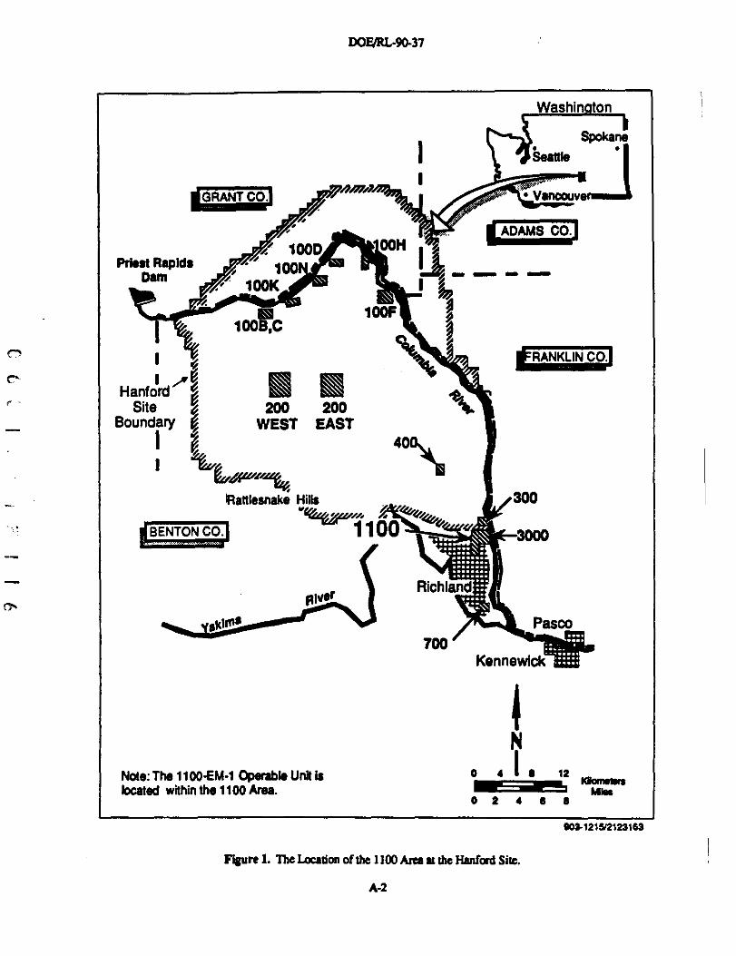
DOFlRL-90-37
,,.
Priest RapidsDam
1
HanfordSite
Boundary
1
200 200WEST EAST
40\
^1atUeanake Hills
BENTON CO.
Note: The 1100-EM-1 Operable Unit islocated within the 1100 Area.
700Kennewiok-M
IN
o 4 1 s 12Kim nip
^ MNs0 2 4 e a
9031216/21231W
Figure 1. The Loeaaon of the 1100 Area at the Hanford Site.
A-2
DOF/RIr90-37
1.4 TASK DESCRIPTIONS
The Phase U investigations at 1100-EM-1 are subdivided into nine individual tasks anda number of activitie:; Individual task scopes are described in detail in Chapter 4.0 of thesupplemental work plan, Sections 4.2 through 4.11. Procedures applicable to the tasksdescribed therein are identified in Chapter 4.0 and Table 2 of this QAPP.
2.0 PROJECT ORGANIZATION AND RESPONSIBILITIES
2.1 PROjECT COORDINATOR RESPONSIBII.ITIES
The Environmental Engineering and Technology function of Westinghouse Hanfordhas primary responsibilities for coordinating the performance of this investigation.Organizational charts are induded in the Project Management Plan (PMP) provided in
-- Chapter 3.0 of the Phase I work plan (DOE-RL 1989) that define personnel assignments andindividual Westinghouse Hanford Field Team structures applicable to the types of tasks
^ induded in this phase of the investigation.
External participant contractors or subcontractors may be evaluated and selected for-- certain portions of task activities at the direction of the project coordinator, in compliance
with Westinghouse Hanford procedures Quality Requirement (QR) 4.0, "ProcurementDocument Control"; Quality Instruction (QI) 4.1, "Procurement Document Control"; QI 4.2,"Extemal Service Control"; QR 7.0,'Control of Purchased Items and Services'; QI 7.1,"Procurement Planning and Control"; and QI 7.2,'Supplier Evaluation (WHC 1989b). The
- primary participant contractor and subcontractor resources for the Hanford Site are listed inFigure 3-2 of the PMP (DOE-RL 1989).
2.2 ANALYTICAL LABORATORIES
The Westinghouse Hanford field sampling team will be responsible for screening allsamples for radioactivity and separating samples Into two groups for further analysis.Samples with levels of radioactivity exceeding background, as detected by standard fieldsurvey equipment, will normally be routed to a Westinghouse Hanford or Hanford Siteparticipant contractor laboratory that is equipped and qualified to analyze radioactivesamples. Samples exhibiting levels of radioactivity exceeding background Will not bereleased to an offsite laboratory based on field measurements, but shall be routed to anappropriate laboratory, measured with laboratory radloanalytical equipment, and thenreleased in accordance with Westinghouse Hanford-approved procedunvs. All analyses shallbe coordinated through the Westinghouse Hanford Office of Sample Management (OSM)and shall be performed in compliance with Westinghouse Hanford-approved laboratory QAplans and analytical procedures. The surveillance controls Invoked by QI 7.3,'SourceSurveillance and Inspection" (WHC 1989b) are applicable to all offsite laboratory operations;QI 10.4,'SurveIDances" (WHC 19896) applies onsite. Applicable quality requirements forsubcontractors or participant contractors shall be Invoked as part of the approvedprocurement documentation or work order as noted in Section 4.1.2. Services of alternatequalified laboratories may be procured for radioactive sample analysis, if onsite laboratory
A-3
DOE/RI.90-37
capacity is not available, and for the performance of split (performance audit) sampleanalysis at the Westinghouse Hanford project coordinator's direction. If such alternatelaboratory services are required, the laboratory QA plan and applicable analyticalprocedures shall be approved.by Westinghouse Hanford before they are used.
2.3 OTHER SUPPORT CONTRACTORS
Procurements of all contracted field activities shall be in compliance with standardWestinghouse procurement procedures as discussed in Sections 2.1 and 4.1 All work shallbe performed in compliance with Westinghouse Hanford-approved QA plans and/orprocedures, subject to surveillance controls invoked by QI 7.3,'Source Surveillance andInspection" for offsite work, or by QI 10.4 "Survei0ances" (WHC 1989b) for onsite work.Applicable quality requirements shall be Invoked as part of the approved procurementdocumentation or work order.
nt
C' 3.0 QUALITY ASSURANCE REQUIREMENTS FOR MEASUREMENTS
- Additional analytical data from soi7 and groundwater sampling activities will beobtained during the Phase II RI at 1100-EM-i; these data shall be evaluated to furthercharacterize the extent and nature of radioactive and hazardous contamination and todetermine the most feasible options for corrective measures. In compliance with theguidelines provided in A Propoaad Data Quality Strategy for Hanford Site Characterization(McCain and Johnson 1990) (which interprets applicable portions of Data Quality Objectivesfor Rcmedial Responses Activities; Volume 1 Development Process (EPA 1987) for use at theHanford Site), two general types of analysis will be performed: (1) rapid response screening
_ analysis; and (2) confirmatory analyses with documentation appropriate to analytical levelsdescribed in the 1100-EM-1 Phase I work plan (DOE-RL 1989).
Screening analyses may involve both field or laboratory methods. Laboratory' methods used for screening purposes may be identical or similar to those later used for
confirmatory analysis, but with less rigorous method-specific QMQC requirements,documentation requirements, and validation requirements. As a consequence, screeningmethods are characterized by quick turnaround times and lower costs; however, they maynot be compound-specific, and the data may be qualitative or only semiquantitative. Datafrom screening analyses must be verified in compliance with Section 8.2.1 before use infocusing subsequent, more detailed stages of the sampling investigation For Phase IIinvestigations at 1100-EM-1, screening analyses will be confined to surface-based radiationsurveys and soil gas surveys using field methods, the results of which will be used to guidemore detailed sampling and laboratory-based analytical Investigations for radioactive andhazardous contaminants. All screening methods will be subject to review and approval byWestinghouse Hanford prior to use.
Fully validated analyses will employ standard EPA reference methods, other standardreference methods, or other methods developed or modified specifically to meet the needs ofthe Hanford Site. All such analyses shall be documented in compliance with Section 8.1and validated in compliance with sections 8.2.2 and 8.2.3, as appropriate for the method
A4
DOF/RIr90-37
concerned. For Phase II investigations at 1104EM-1, such analyses will be performed using
standard EPA reference methods as noted in Table 1. Table 1 identifies target values for
detection limits, precision, and accuracy that must be adjusted and/or confirmed and
accepted by Westinghouse Hanford and the proposed laboratory before final approval of
associated subcontracts or work orders. Once these values are established as contractualrequirements in compliance with standard procurement procedures (see Section 4.1), Table Ishall be updated to reference approved detection limit, precision, and accuracy criteria asproject requirements; all such changes shall be documented in monthly unft managers'meeting minutes as required by Section 6.6 of EII 1.9, "Work Plan Review" (WHC 1989c).
Goa1s for data representativeness are addressed qualitatively by the specification ofsampling locations and intervals within the Chapter 4.0 and Figures 4-1 through 4-18 of thesupplemental work p1an. Objectives for completeness for this investigation shall requirethat contractually or procedurally established requirements for precision and accuracy bemet for at least 90% of the total number of requested determinations. Failure to meet thiscriterion shall be evaluated in the data assessment process described in Chapter 12.0, andshall be subject to any necessary corrective action as discussed in Chapter 13.0. Approvedanalytical procedures shall require the use of reporting techniques and units specified in theEPA reference methods in Table I to facilitate the comparability of data sets in terms ofprecision and accuracy.
4.0 SAMPLING PROCEDURES
4.1 PROCEDURE APPROVALS AND CONTROL
4.1.1 Westinghouse Hanford Procedures
-- The Westinghouse Hanford procedures cited in this QAPP have been selected fromthe Quality Assurance Program Index induded in the WHC-SP-0447 (WHC 1989a). Selectedprocedures include EIIs from the Environmental Investfgativns and Site Chanutniratron Manual(WHC 1989c), QRs and Qls from the Weatinghouse Hanford Company Quality AssuranceManual (WHC 1989b), and procedures from the Operational Herdth Physics Practices Manual(WHC 1988). All procedures are listed In Table ?„ cross referenced to Individual subunitinvestigations by applicability. Procedure approval, revision, and distribution controlrequirements applicable to Ells are addressed in EII 1.2, "Preparation and Revision ofEnvironmental Investigations Instructions" (WHC 1989c); requirements applicable to QIsand QRs are addressed in QR 5.0,'7nstructions, Procedures, and Drawings"; QI 5.1,"Preparation of Quality Assurance Documents"; QR 6.0,'Doeument Control"; and QI 6.1,"Quality Assurance Document Control" (WHC 1989b). All procedures shall be madeavailable for regulatory review on request at the direction of the Westinghouse Hanfordproject coordinator.
A-5
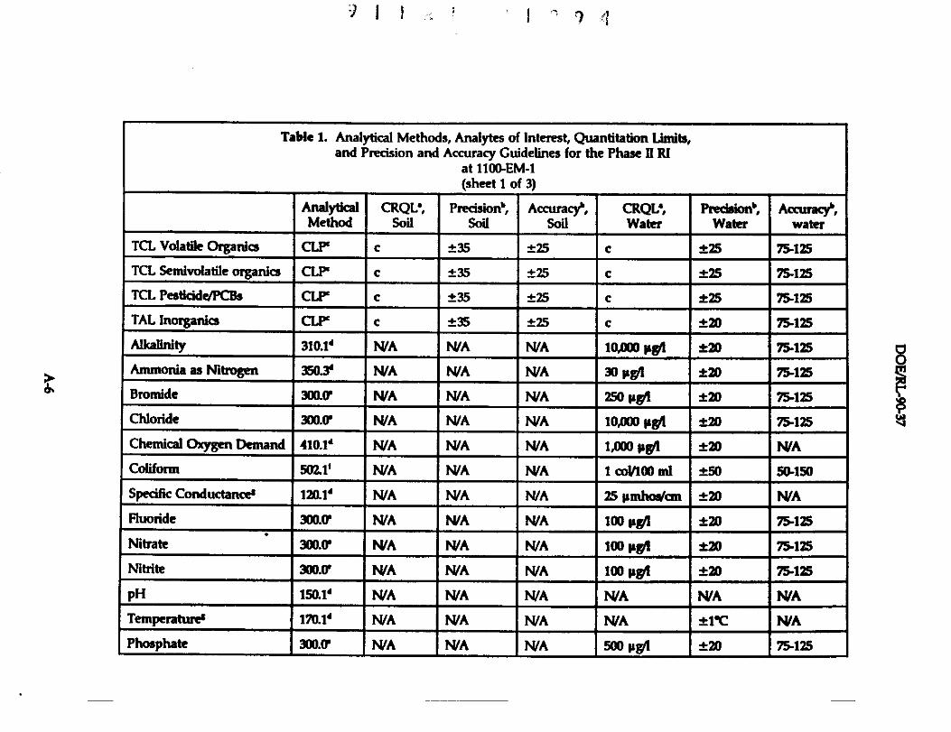
Table 1. Analytical Methods, Analytes of Interest, Quantitation Lindts,and Precision and Accuracy Guidelines for the Phase 11 RI
at 1100-EM-1(sheet 1 of 3)
AnalyticalMethod
CRQL',Soil
Pnecision',Soil
Accuracyr,Soi(
CRQL;Water
Pnecieionb,Water
Accvracy',water
TCL Volatile Organio CLP` c ±35 ±25 c ±25 75-125
TCL SemivolaHle organica CLP` c ±35 ±25 c t25 75-125
TCL PestiddelPCBs CLP` c ±35 ±25 c t25 75-125
TAL Inorganics CLP` c ±35 ±25 c ±20 75•125
Alkalinity 310.1' N/A N/A N/A 10,000 µgt ±20 75-125
Ammonia as Nitrogen 350.3' N/A N/A N/A 30 µg4 ±20 75-125
Bromide 3000 N/A WA N/A 250 µgf ±20 75-125
Chloride 300.0' N/A N/A N/A 10,000 pgl ±20 75-125
Chemical Oxygen Demand 410.1' N/A N/A N/A 1,000 p94 f20 WA
Coliform 5011' N/A N/A N/A 1 coV100 mt ±50 50-150
Specific Conductanee$ 120.1' N/A N/A NIA 25 µmhoa/mt ±20 WA
Fluoride 300.0' NIA N/A N/A 100 µg/1 ±20 75-125
Nitrate 300.0' NIA N/A N/A 100 µgl ±20 75r125
Nitrite 300.0' N/A N/A N/A 100 µgR ±20 7r125
pH 150.1' WA N/A N/A N/A N/A WA
Temperatures 1T0.1' WA N/A N/A WA ±1'C WA
Phosphate 300.01 NIA WA WA 500 µWI ±20 7r1Z5
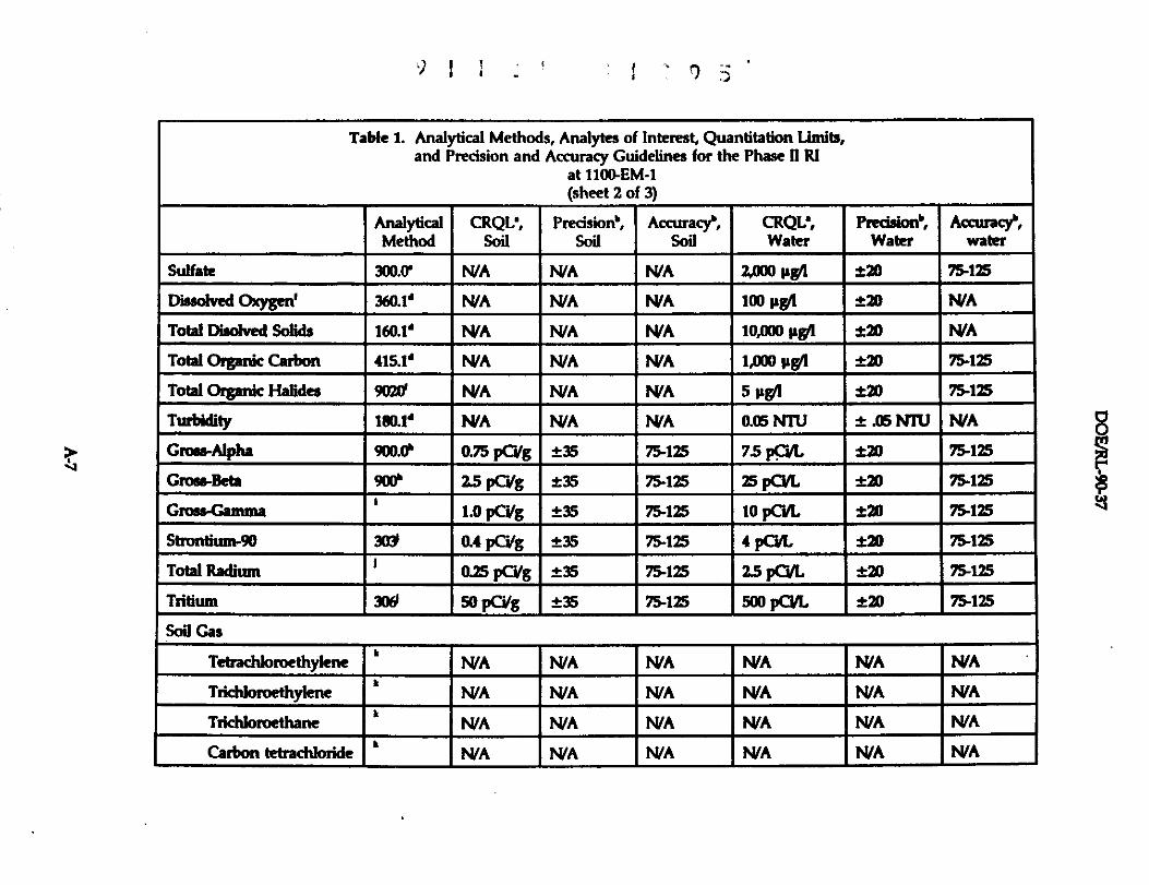
'^
•J/ ./ •
Table 1. Analytical Methods, Analytes of Interest, Quantitation Limits,and Precision and Accuracy Guidelines for the Phase II RI
at 110QEM-1(sheet 2 of 3)
AnalyticalMethod
CRQL',Soil
Pnedsion',Soil
Acauacy`,Soil
CRQL',Water
Predaion`,Water
Accvrac)^,water
Sulfate 300.0' WA WA WA $,000 pgyl ±20 75-125
Dissolved Oxygen' 360.14 WA N/A NA 100 µgA ±2D WA
Total Disolved Solids 160.1' WA WA WA 10,000 µwl ±20 WA
Total Otgar3c Carbon 415.1' WA WA WA 1,000 µwl ±20 75-125
Total Organic Halides 9020' WA NA N/A 5 µgA ±20 75-125
Turbidity 180.1d wA WA wA 0.05 NTU ±.O6 NIV NA
Grnss-Alpha 900.0' 0.75 pC/g ±35 75-125 7.5 pCil[, t20 75-125
Grose-Beh 900'' 2.5 pCdg ±35 75-125 25 pCYL t20 75-125
Grass-Gamma 1.0 pCi/g ±35 75-125 10 pC'ill. +20 75a125
Sttorttium-90 30Y 0.4 P6/g ±35 75-125 4 pCili, ±20 75-125
Total Radium 10.25 pCa/g ±35 75-125 25 pCUL ±20 75-125
Tritium 300 50 pCJg ±35 75-125 500 pCYL ±20 75-125
Sa7 Gas
Tetrachloroethylene ` WA WA WA WA NA WA
Trid+loroethylene N/A WA WA N/A WA WA
Triddoroethane ` IV/A N/A WA HUA NA WA
Carbon Mtrachloride ` N/A WA WA WA WA WA
S^^^

1 I I v' 1'q ^
Table 1. Analytical Methods, Analytes of Interest, Quantitation Limits,and Precision and Accuracy Guidelines for the Phase H RI
at 1100.EM-1(sheet' 3 of 3)
t
Analytical I CRQL', I Precision°, I Accuracy°, CRQL•, Predsion', I Accuracy',Method Soil Soil 9oil Water Water water
`CRQL = Contract required quantitation limit; values are to be considered requirements in the absence of known ofsuspected analytical interferences which may hinder achievement of the limit by the contract laboratory.°Precision is expressed as relative percent difference; accuracy is expressed as pencent recovery. These limits apply to
sample results greater than five times the CRQL and are to be considered requirements in the absence of known orsuspected analytical interferences which may hinder achievement of the limit by the contract laboratory.`CLP = methods contained in EPA 1988a and EPA 1986b.'Methods are from EPA 1979.Methods are from Lindahl 1984.Methods are from EPA 1986a.Warameter measured in the field."Methods are from Krieger and Whittaker 1980.Methods are from DOE 1987.Methods are from APHA 1985.`Methods and quantitation limits shall be developed in compliance with Westinghouse Hanford or Westinghouse
Hanford-approved participant contractor or subcontractor procedures.
O
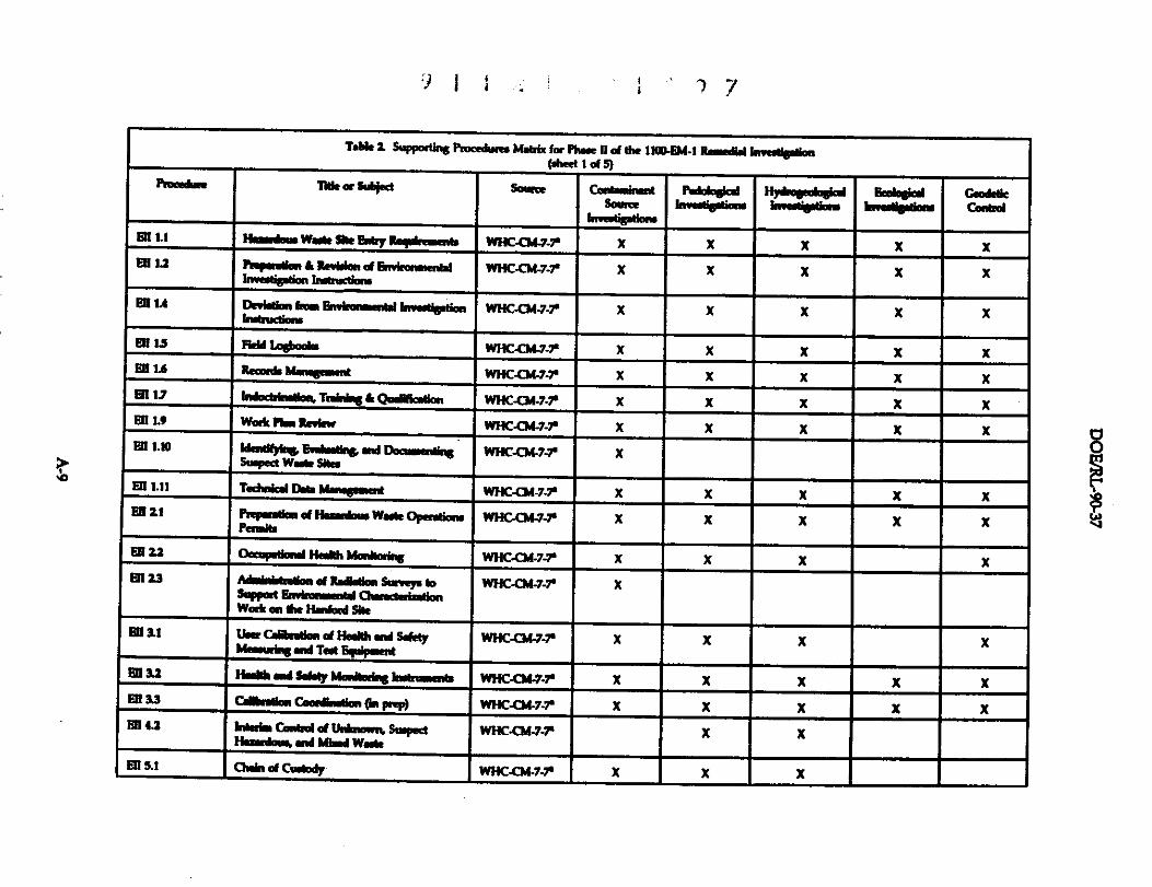
1) ! ; i ; -) -/
>̂
'd61e 2. Sappmtin6 Pmndwa MNr6r for Phue p of the 1100.6Md Rsedd 4naYptlm(Ahael 1 of 5)
~°°wwo Tltls«SijsR Somne CmMomLwt
^PedolnakdM^^
Hpiosedu@nlti^^
Beoy"^Mbn
GaaddkCanhd
w.b as ery I -.^5 wxc.cwa-r x x x x x®L2 P•p.WmkRe.rm d En.ronwAner
a."496on h.emeum.WHC-CM-7-r x x x x x
^^A Devfew BnoiarwnYl Nwbptiaebubwesma
WNC-CM-7-7- x x x x x
ER 13 Fam Ledboob WHCQW-r x x x x xEN I'6 R Mwugmmt WHC-CM-7-r x x x x xm v Idue4^TnWMk QuYlRotloe WHC-CM-7-r x x x x xEn 1•9 wO* Plan Rawkw WHC-CM-7-r x x x x x® 1.10 WedWyY* 6wlmdg% wd DonrMin
&rped WoAe SiOsWHGCM-7A' x
°1 1•11 T°^" DabM^ wMC-c]Aa-r x x x x x® 11 rRp..tlw u( w w.we opedia.
penwbwHG044-7' x x x x x
® u °a^ Ii MmAmins WHC-CM-7-r x x x xIM 2.3 A .r R.at.um sonvp to
sWpore bwhmmorr aw.aukasmwaek m the H.gona She
WHC-CM-7-r x
®&I oftb.xti.W s.ktytde.Wins «r T.e &pip.ene
wE+c43a-r x x x x
®&2 Hmkbm+SWds b--dlorbs^ wHcora.r x x x x x®M cambla"r,& OR rl* wHC43da-r x x x x x®u rw^+. cana of uww„,n, s=poa
F^a^w6 .ea Now w..kwxc.casa-r x x
®^1 Chai^ of CadDds wHGCTt-7-r x x x
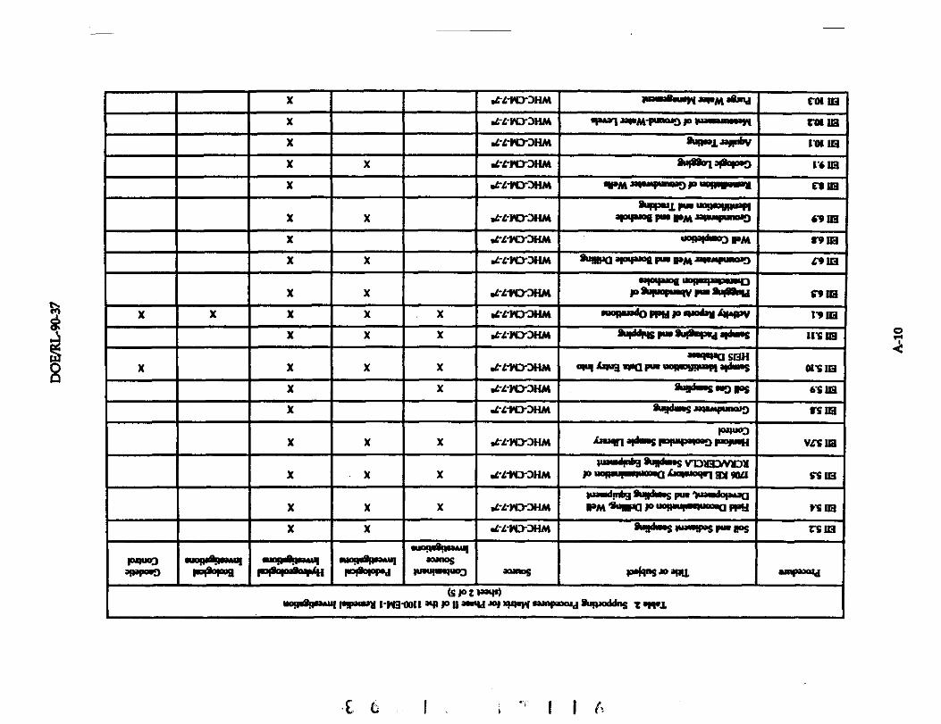
ren
^
^Q
G.]
X d-L-PD-JHM 7WmamMMIaNM+axN COl in
X .L-L-PL7JNM OPWI+'+PM-WKU'JP panumaYI TOl in
X 1-L-PD'3HM &Po1+WibY 1109 m
X X dY-Ml7'JHM ANn7 *°m 1*6 m
X d-L-YO'JHM 4PM japmpwApJ lB UPPlWANll Et m
X X .L-M'JHM94im1 Pw U0.qwqpwK
aPWmi PM PM JBMMFURDI'J 6'9 in
X d-L-PD-JHM vopvkooJ PM f'9 m
X X d-L-PD-JHM amm aNWwi PW PMMwmPmD C91Ci
X X d'L-WJ'Jm64OWmI UOREIMPaMOD
PSwoPm9VM20090Y 4'9A8
X X X X x d-LFO'JHM awlMwdO now p w O&'y LMaNiV 17 m
X X X .G-L-ND-JHM Soft FMEO+I&AVS tCi m
X X x xaOmPM SfdN
wyAwe .raww wowuman aomn asm
x x dY-NC7JHM &moonK go'J PS 6'4 in
x d-L-PO-JHM &•da=S m"mpmDjJ vs in
x x x .rc-r3-3mPJPW3
A=Mn 8OWW5 P"wW85 r4rwx vcs in
x x x 1•L-W7JHMwmdpft &Ro+m vv13ymn
Puopmpwpwma lwMmIrI Hx 9BLl S'S to
x x x dYrND-JHMWaNdlnb9 ARIWsPM 9NmPC1 Puop^ PpH Vc m
x x .c-L-wTJFiM Swhns P*RWS rr Ps zY m
pq^ wnpdq^.y ^eniw+.u^ .uon^wwP*wwa
*ppa!w.N^^Os
WN"04uoa M*es po(vn +oMnu ^a
(swzI^n)WIIAl" PTawX Ciq-ODl1 an P 0no9d +l miPW ti^Pwod &Rod&B t+w1
0
^. ^: ^,.^ ^ :- k ^^^ ^ ( E•
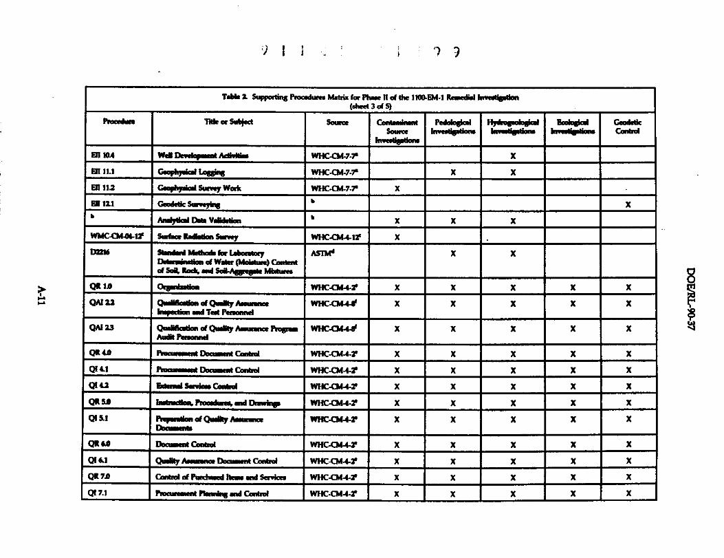
..
) I
T" i Sapportins PROad^ M.4ix (ur phre tl of the 1106GM-1 Rewednl hweitlptlon(shcel 3 of S)
Piooedme Tltle or Sub)ed Sanae CadrnrASowaa
h mdando
Pdabpd HrLo8dudialYn^tleMfon
Badnpdi^eAinlb^r
CaoilkConhd
Bll 1G4 Wd Dndqmrrt ktlvNis WHC-CMJ-T x
fill 11.1 CwopA)id 1aSOW WHC-CM-7-7a x x
F7111s Gooogiul $aewy Waak WHC.CM-7.r x
®121 Caadetla Sameying6
x
b aryud o.ee vdd.uon b x x x
WMC17A441r Suhae Raitlm Swvey WHGQi-41r x
D7216 8we.a M1Ma (ar (.eud"Ddemirtlm at WMQ (MdMre) Caeledof Sal. Ra'k ad SoY-AepegNe ANftrar
ASIM+ x x
QR IA Oepmbslbn WHC-O/a -r x x X x X
QAI 22 Q^ibatlen at QrIMy Arwmmeehrpection rd Tst Paoamd
WHC-Q" x x x x x
QAI 23 Qd'lltlon d QwWyAmMWna PMp^Aoit Pamard
WHC.Gt44 X X X X X
QR+o na._ oa,.ftt cont.a WHaa"r x x x x xQ( u RmmsmR Dnaumat Cawol WHC-CM+r x x x x x
Q( 4.1 &Mal Sa^kw Camd WHGWI-r x x X x x
QR sA naao,..rp Wxa4M4l-2' x x x x x
Q( S.1 PrwwMiuw of Qwft Awemoeoavew
WfC-CMJI-r x x x x x
QRU Duamart Conud WHC-Q44-r x X x x x
of a1 cmft e.^... o^.I cor*rd WHC-CM+r X X X x x
QR » cOMMA of ewa..a >«..aw sR.'m WHC-Cut+r x x x x xQ17•1 RoawsKnt rMeeY% wd C.oo6d WHC-C^ X X X X X
wV
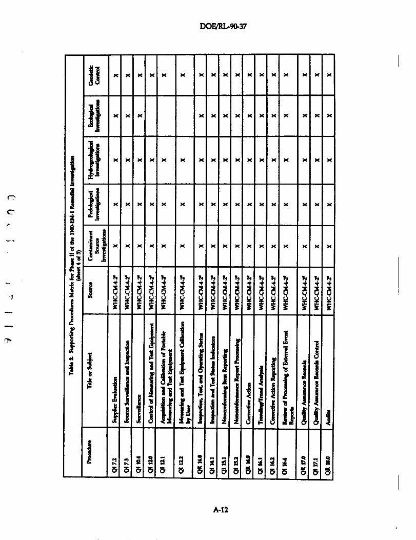
DOFJRIr9U-37
x x x x x x x x x x x x x x x x x
x x x x x x x x x x x x x x
^ x x x x x x x x x x x x x x
F i xx
x x x x x x x x x x x x x x x x x
^d^
x x x x x x x x x x x x x x x x x
h fV t^ !a t^ ta A ?^ T^ ta Ta H A f^ ^y ta A
^
lS
^ . .^^ fr I ^ ^
'a S S S S 'a S S S a S S S S ^
A-12
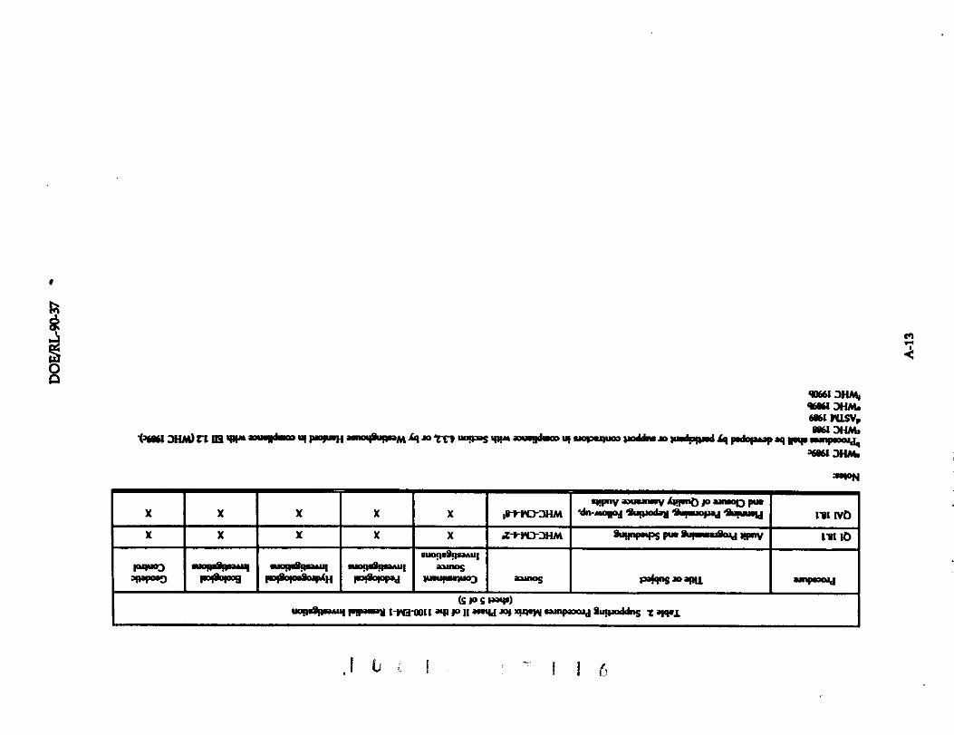
^^
90fi61 JHhy96Y61 JHA+.er" rasv,
i^fau ^HM) rt ® 4^w m^II^ y PmrH ^RwM^y m t^rr ^s 4^^iR^voadn. nvwdppwd ty P.a^a.ap aq wy.^
361" 3tu+.
4!wrvwuw^vAmnbw&^ormx x x x x ,rrrD-JHM Idw-ear %}1obM%qmwYM 'Arn=la l7[ rva
x x x x x stwrJHM A!I"PS PpM A'!mmaismM NPov l9l la
."aq^lww^o Amn+nWw awpwhpa" *^l a"ws342pos'J pm.9opM p*MmVa9AH P-.9WWd ww!m"po'J O=WS A49"WaIK1. &NWy°jd
(swsI-w)wRv9m^I FlP" t-W3-0011 an N 11 amW Jo1 x4+MW WAP300+d 9UP-ddnS s aIWt
^
DOE/RL-9Q37
This page intentionally left blank.
FnM1
T
A-14
DOE/RL.90-37
4.1.2 Participant Contractor/Subcontractor Procedures
As noted in Section 2.1, partidpant contractor and subcontractor services shall be
procured under the applicable Westinghouse Hanford procedures. Whenever such servicesfor Westinghouse Hanford are required, requirements for the review and approval of allapplicable procedures shall be induded in the procurement document or work order, asapplicable. In addition to the submittal of analytical procedures, analytical laboratories shallbe required to submit the current revision of their Internal QA program plans. Prior to use,all analytical laboratory plans and procedures shall be reviewed and approved by qualifiedpersonnel, as directed by the project coordinator; all reviewers shall be qualified under therequirements of EII 1.7, "Indochination, Training, and QuaNfication" (WHC 1989c). Allparticipant contractor or subcontractor procedures, plans, and/or manuals shall be retainedas project quality records In compliance with EII 1.6,'Records Management' (WHC 1989c);QR 17.0,'Quality Assurance Records"; and QI 17.1,'Quality Assurance Records Control"(WHC 1989b). All such documents shall be made available for regulatory review on requestat the direction of the Westinghouse Hanford project coordinator.
r" 4.13 Procedure Change Control
Deviations from established EIIs that may be required in response to unforseen fieldsituations may be authorized in compliance with Ell 1.4, "Deviation from EnvironmentalInvestigations Instructions'(WHC 1989c). Documentation, review, approval, and dispositionrequirements shall be as specified therein. Other types of change requests applicable toQRs and QIs shall be approved, as required, by QR 6.0, 'Document Control", and Ql 6.1,"Quality Assurance Document Control" (WHC 1989b). Deviations from established radiationsurveying and monitoring procedures shall be authorized only within applicable portions ofthe guidelines established by the Operational Health Physics Practices Manual, WHC-CM-412(WHC 1988). As noted in Section 1.4 above, interim changes to this QAPP, thesupplemental work plan, or other plan-level documents shall be documented, reviewed, andapproved in compliance with Section 6.6 of EII 1.9, "Work Plan Review" (WHC 1989c).
4.2 SAMPLING PROCEDURES
4.2.1 Soil Sample Acquisition
All soil sampling shall be conducted in compliance with Ell 5.2, "Soi1 and SedimentSampling' (WHC 1989c). Borehole drilling in support of soil sample acquisition shall be incompliance with ED 6.7, "Groundwater Well and Borehole Drilling"(WHC 1989c). Otherapplicable Elis and procedures related to soil sampling activities are sped8ed in Table 2.
4.22 Water Sample Acquisition
All water sampling shall be performed in compliance with EII 5.8, "GroundwaterSampling.' Other Ells and procedures related to water sampling, groundwater wellinstallation, development, and maintenance are specified in Table 2.
A-15
DO11RL.90-37
4.2.3 Soil Gas Sample Acquisition
All soil gas sampling shall be conducted in compliance with EII 5.9, "Soi1 GasSampling"; other supporting procedures and EIIa are specified in Table 2
4.3 SAMPLE IDENTIF'ICATION, LOCATION, AND FREQUENCY
The sample identification described in EII 5.10'Sample Identification and Data Entryinto HEIS Database" (WHC 1989c) which is in preparation, will be used to designatesamples obtained during the Phase II RL
Sample location and frequency shall be as defined in Chapter 4.0 of the supplementalwork plan (see Sections 4.2 through 4.8 and Figures 4-1 through 4-19). Field quality control(QC) sample frequendes shall meet the minimum requirements defined in Chapter 9.0below.
4.4 SAMPLE CONTAINER PREPARATION, HANDLING, PRESERVATION,AND SHIPPING
_ Sample container selection, preparation, and preservation shall be as specified in EII5.2, "Soil and Sediment Sampling"; EII 5.8, 'Groundwater Sampling"; or EII 5.9, "Soil GasSampling" (WHC 1989c), as appropriate for the type of sample involved. All samples shallbe packaged and shipped in compliance with the applicable requirements of Ell 5.11,"Sample Packaging and Shipping" (WHC 1989c), subject to the chain of custody controlsdescribed in Chapter 5.0 below.
4.5 SAMPLING EQUIPMENT DECONTA111Q1ATION
- Field support equipment and sample acquisition equipment shall be decontaminatedprior to use as required by EII 5.4, "Field Decontamination of Drilling, Well Development,
cr` and Sampling Equipment", and/or EII 5.5, "Decontamination of Equipment forRCRA/CERCLA Sampling" (WHC 1989c), as appropriate for the equipment type.
S.0 SAMPLE CUSTODY
All samples obtained during the course of this investigation shall be controlled, asrequired, by EII 5.1 'Chain of Custody" (WHC 1989c) from the point of origin to theanalytical laboratory. Laboratory chain-of-custody procedures shall be reviewed andapproved in compliance with the requirements of Section 4.1 above, as applicable, and shallensure the maintenance of sample integrity and identification throughout the analyticalprocess. At the direction of the Westinghouse Hanford project coordinator, requirementsfor the return of residual sample materials after completion of analysis shall be defined inaccordance with procedures defined in the procurement documentation to subcontractor orparticipant contractor laboratories. Chain-of-custody forms shall be initiated for returned
A-16
DOEIRL-90-37
residual samples, as required by the approved procedures applicable within the laboratory.
Results of analyses shall be traceable to original samples through the unique numerical
sample identifier discussed in Chapter 4.0 and Table 3 above. All analytical results shall becontrolled as permanent project quality records as required by QR 17.0, "Quality AssuranceRecords," (WHC 1989b) and EII 1.6,' Records Management,' (WHC 1989c).
6.0 CALIBRATION PROCEDURES
Calibration of all Westinghouse Hanford measuring and test equipment, whether inan odating inventory or purchased for this investtgation, shall be controlled as required byQR 12.0, "Control of Measuring Test Equipment; QI 1Z1, "Acquisition and Calibration ofPortable Measuring and Test Equipment' (WHC 1989b); QI 12.2, "Measuring and TestEquipment Calibration by Uset' (WHC 1989b); Ell 3.1, "User Calibration of Health andSafety MdsTE" (WHC 1989c); and/or WHC-CM-4-12 (WHC 1988). Routine operational
^ checks for Westinghouse Hanford field equipment shall be as defined within applicable Ells,^ procedures or governing manual sections; similar information shall be provided in
Westinghouse Hanford-approved participant contractor or subcontractor procedures.
Calibration of laboratory analytical equipment shall be as defined by WestinghouseHanford-approved laboratory QA project plans or the applicable reference methodsspecified in Table 1.
7.0 ANALYTICAL PROCEDURES
Analytical methods identified in Table 1 shall be selected or developed and approvedbefore they are used, in compliance with appropriate Westinghouse Hanford procedureand/or procurement control requirements. As noted in Section 3.0, Table I provides generalguidelines and reference sources for target contractual quantitation limits and target valuesfor precision and accuracy for each analyte of interest Once Individual laboratorystatements of work are negotiated, and procedures are approved in compliance with therequirements of Section 4.1.$ Table 1 shall be revised to include actual method references,approved contractual quantitation limit, precision, and accuracy criteria as projectrequirements; all such changes shall be documented as required by Section 6.6 of Ell 1.9"Work Plan Review" (WHC 1989c), and shall be documented as part of monthly unitmanagers' meeting minutes.
All analytical procedures approved for use in this investigation shall require the useof standard reporting techniques and units to facilitate the comparability of data sets interms of precision and accuracy. All approved procedures shall be retained in the projectquality records and shall be available for review upon request at the direction theWestinghouse Hanford project coordinator.
A-17
DOEIUr9a37
to DATA REDUCTION, VALIDATION, AND REPORTING
&1 DATA REDUCITON AND DATA PACKAGE PREPARATION
All subcontractor or participant contractor analytical laboratories shall be responsiblefor preparing a report summarizing the results of analysis and for preparing a detailed datapackage that includes identification of samples, sampling and analysis dates, raw analyticaldata, reduced data, data outliers, reduction formulae, recovery percentages, quality controlcheck data, equipment calibration data, supporting chromatograms or spectrograms, anddocumentation of any nonconformances affecting the measurement system in use duringsample analysis. Data reduction schemes shall be contained within individual laboratoryanalytical methods and/or QA project plans, subject to Westinghouse Hanford review andapproval as discussed in Section 4.1. The completed data package shall be reviewed andapproved by the analytical laboratory's QA manager before it is submitted to theWestinghouse Hanford Office of Sample Management (OSM) for validation. Therequirements of this section shall be included in procurement documentation or workorders, as appropriate, in compliance with standard Westinghouse Hanford procurement
`- control procedures noted in Section 4.1.
8.2 VALIDATION
Data validation shall be performed by the Westinghouse Hanford OSM in compliancewith procedures approved by the project coordinator. At a +++i*++*++um, OSM data validationprocedures shall meet the requirements of Sections 8.2.1, 8.12, and 8.2.3 below.
8.2.1 Screening Analyses - Verification and Report Preparation Requirements
- Screening analyses shall have been performed in compliance with Westinghouse_ Hanford-approved procedures, as noted in Section 4.1. Verification of screening data
quality shall be in compliance with applicable Westinghouse Hanford Ells; verification ofscreening data obtained using laboratory methods shall, at a minimum, be verified bycomparison with laboratory data validated in compliance with Sections 8.2.2 and 8.13below.
8.2.2 Standard Analyses - Validation and Report Preparation Requirements
All standard procedure analyses shall be validated in general compliance withWestinghouse Hanford Sampk Management Administration Manual WHC-CM-5-3 (WHC1990), Section 2.2, for organics analyses and Section 2.1 for inorganics analyses.
8.2.3 Special Analyses - Validation and Report Preparation Requirements
All validation of radionuclide analyses shall be performed in compliance with specificprocedures developed by the OSM; all such procedures shall be approved by the OperableUnit Technical Coordinator, and shall address the following minimum requirements:
A-18
DOF/RIr90-37
• review of calibration data for each
• review of verification data for determination of lower limit of detection (LLD)and/or minimum detectable activity (MDA)
• review of blank data
• review of spike sample recovery data
• review of detector efficiency calculations and data for each applicablegeometry
• review of counting error calculation data
• review of ingrowth correction factors, as applicable to sample resultcalculations
^" • review of duplicate analysis datar
• review of laboratory control sample data
• verification of receipt of all raw data for all instruments used to report sampledata, plus all routine QMQC data
• verification of receipt of all analytical results in compatible electronic format
• review of chain of custody records.
Validation of all organic and inorganic samples in radioactive matrices shall be incompliance with Section 8.2.2 above.
^ 8.3 FINAL REVIEW AND RECORDS MANAGEMENTc^ CONSIDERATIONS
At the discretion of the Westinghouse Hanford projed coordinator, all screeningverification reports, validation reports and supporting analytical data packages shall besubjected to a final technical review by a qualified reviewer before they are submitted to theregulatory agencies, or are induded in reports or technical memoranda. All reports, datapackages, and review comments shall be retained as permanent project quality records incompliance with EII 1.6, "Records Ivfanagement" (WHC 1989c), and QR 17.0,'QualityAssurance Recorda" (WHC 1989b).
9.0 INTERNAL QUALTTY CONTROL
All analytical samples shall be subject to in-process QC measures in both the field andthe laboratory. The following minimum field QC requirements apply for validated analyses.
A-19
DOF/ItL-9o-37
These requirements are adapted from Test Methads for Evaluating Solid Waste (EPA 1986b), asmodified by the proposed rule changes induded in the Federal Register, 1989, Volume 54,No. 13, pp 3212-3228, and 1990, Volume 55, No. 27, pp 44404445.
Field duplicate samples: For each shift of sampling activity under anindividual sampling subtask, a minimum of 5% of the total collected samplesshall be duplicated. Duplicate samples shall be retrieved using the sameequipment and sampling technique and shall be placed into two identicallyprepared and preserved containers. All field duplicates shall be analyzedindependently as an Indication of gross erron in sampling techniques.
• Split sample's: At the Westinghouse Hanford project coordinator's direction,field or field duplicate samples may be split in the field and sent to analternate laboratory as a performance audit of the primary laboratory.Frequency shall meet the minimum schedule requirements of Chapter 10.0.
r,,, • Blind samples: At the Westinghouse Hanford project coordinator's direction,blind or double-blind reference samples may be introduced into any sampling
C! round (in lieu of split samples) as a performance audit of primary laboratory.Blind sample type and frequency shall be as directed by the WestinghouseHanford project coordinator; frequency shall meet the minimum schedulerequirements for performance audits described in Chapter 10.0.
• Field blanks: Field blanks shall consist of pure deionized distilled water,transferred into a sample container at the site and preserved with the reagentspecified for the analytes of interest Field blanks are used as a check onreagent and environmental contamination and shall be collected at the samefrequency as field duplicate samples.
• Equipment blanks: Equipment blanks shall consist of pure deionized distilled- water washed through decontaminated sampling equipment and placed in
containers identical to those used for actual field samples. Equipment blanksare used to verify the adequacy of sampling equipment decontaminationprocedures and shall be collected at the same frequency as field duplicatesamples.
Trip blanks: Trip blanks consist of pure deionized distilled water added to onedean sample container, accompanying each batch of containers shipped to thesampling activity. Trip blanks shall be returned unopened to the laboratoryand are prepared as a check on possible contamination originating fromcontainer preparation methods, shipment, handling, storage, or site conditions.In compliance with standard Westinghouse Hanford procurement procedures,requirements for trip blank preparation shall be included in procurementdocuments of work orders to the sample container supplier and/or preparer.
Internal QC checks for fully validated analyses shall be as specified by thelaboratory's approved QA plan and shall meet the following minimum requirements:
• Matrix spike/matrix spike duplicate samples: Matrix spike and matrix spikeduplicate samples require the addition of a known quantity of a representative
A-20
DOF/RI.-90-37
analyte of interest to the sample as a measure of recovery percentage and as atest of analytical predsion The spike shall be made in a replicate of a fieldduplicate sample. Replicate samples are separate aliquots removed from thesame sample container in the laboratory. Spike compound selection,quantities, and concentrations shall be described in the laboratory's approvedanalytical methods. One sample shall be spiked for each analytical batch, oronce every 20 samples, whichever is greater.
• QC reference samples: A QC reference sample shall be prepared from anindependent standard at a concentration other than that used for calibration,but within the calibration range. Reference samples are required as anindependent check on analytical technique and methodology and shall be runwith every analytid batch, or every 20 samples, whichever is greater.
The minimum requirements of this section shall be invoked in procurementdocuments or work orders, in compliance with standard Westinghouse Hanford proceduresas noted in Section 4.1.
c^^
r
10.0 PERFORMANCE AND SYSTEM AUDTTS
Performance, system, and program audits are scheduled to begin early in theexecution of this work plan and continue through work plan completion. Collectively theaudits address quality affecting activities that include but are not limited to, measurementsystem accuracy, intramural and extramural analytical laboratory services, field activities,and data collection, processing, validation and management
Performance audits of the accuracy of laboratory analysis are implemented inaccordance with Standard Operating Procedure Ell 1.12 "Laboratory Analysis PerformanceAudits" (WHC 1989c) which is in preparation. System audit requirements are implementedin accordance with Standard Operating Procedure QI 10.4, "Surve9Ilance" (WHC 1989b).
r", Surveillances will be performed regularly throughout the course of the work plan activities.Additional performance and system "surveMances" may be scheduled as a consequence ofcorrective action requirements, or may be performed upon request All quality affectingactivities are subject to surveillance.
All aspects of inter-operable unit activities will also be evaluated as part of routineenvironmental restoration program-wide QA audits under the Standard OperatingProcedure requirements of WHC-CM-4-2 (WHC 1989b). Program audits shall be conductedin accordance with QR 18.0,'Audits; "Audit Programming and Scheduling (WHC 1989b),'and QAI 18.1,'Planning, Performing, Reporting, and Follow-up, and Ciosure of QualityAudits" by auditors qualified in accordance with QAI 2.3, "Qualification of QualityAssurance Program Audit Personnd" (WHC 1990b).
A-21
DOF/RL-90-37
11.0 PRBV6N11VE MAINTENANCE
All measurement and testing equipment used in the field and laboratory that directlyaffects the quality of the field and analytical data shall be subject to preventive maintenancemeasures that ensure minimization of measurement system downtime and correspondingschedule deLys. Laboratories shall be responsible for performing or managing themaintenance of their analytical equipment Maintenance requirements, spare parts list, andinstructlons shall be included in individual methods or in laboratory QA plans, subject toWestinghouse Hanford review and approvaL Westinghouse Hanford field equipment shallbe drawn from inventories subject to standard preventive maintenance procedures. Fieldprocedures submitted for Westinghouse Hanford approval by participant contractors orsubcontractors shall contain provisions for preventive maintenance, maintenance schedules,and spare parts lists to ensure minimization of equipment downtime.
c'a12.0 DATA ASSESSMENT PROCEDURES
As noted in Section 4.9 of the supplemental work plan, the data generated during the- Phase II RI will be monitored on an ongoing basis. Data evaluation summaries shall be
prepared and reported to the project coordinator on a monthly basis in order to facilitateany necessary redirection or emphasis of the characterization effort Where data aregenerated in sufficient quantity to warrant such analysis, the project coordinator may directthe application of specific statistical or probabilistic techniques in the process of datacomparison and analysis. Such techniques are likely to indude the calculation of tolerancelimits, and the calculation of confidence limits, as discussed in the following sections.
12.1 TOLERANCE LIIVIIT CALCULATIONS
Each hazardous substance has a certain background distribution in a given`' environmental medium. Before a substance can be regarded as a site-specific contaminant,
it must be found to occur at concentrations exceeding (or for pH, lying outside) the localbackground distribution. Site-specific tolerance limits will be calculated to make thesedeterminations in an objective manner.
All rnvironmental-medium-speoific background distributions will be assumed to benormal, unless non-normality can be demonstrated. One-sided tolerance limitscorresponding to the 95th percentile of the background distribution, with a degree ofconfidence of 95%, will be calculated in accordance with the methodology provided in EPA(1989a). Two-sided tolerance limits corresponding to the 5th and 95th percentiles of thebackground distn'bution, with a degree of confidence of 95%, will be calculated for pH inaccordance with the methodology provided in Miller and Freund (1965).
A-22
DOF/RLr90-37
12.2 CONFIDENCE LIMIT CALCULATIONS
During a baseline risk assessment, reasonable maxdmum exposures concentrations andother factors are estimated. In accordance with EPA (1989b), reasonable maxdmum riskassessment factors are calculated by substituting a mean value with a conservatively biasedestimate of the mean. Such estimates are obtained from the calculation of an upper orlower (whichever provides the conservative estimate) confidence limit of the distribution ofthe mean.
Mean value distributions used in exposure assessment will be assumed to be normal.One-sided, 95% confidence limits will be calculated in accordance with the methodologyprovided in Miller and Freund (1965).
13.0 CORRECTIVE ACTION
Corrective action requests required as a result of surveillance reports,nonconformance reports, or audit activity shall be documented and dispositio0ed asrequired by QR 16.0,'Correcflve Actfon"; QI 16.1,'Trending/Prend Analysis"; and QI 16.2,"Corrective Action Reporting" (WHC 1989b). Other measurement system procedure or plancorrections that may be required as a result of data assessment or routine review processesshall be resolved as required by governing procedures or shall be referred to theWestinghouse Hanford project coordinator for resolution. Copies of all surveillance,nonconformance, audit, and corrective action documentation shall be routed to the projectquality records upon completion or dosure.
-- 14.0 QUALTTY ASSURANCE REPORTS
As previously stated in Chapters 10.0 and 13.0, project activities shall be regularlyassessed by performance and system auditing and associated corrective action processes.Surveillance, nonconformance, audit, and corrective action documentation shall be muted tothe project quality records upon completion or dosure of the activity. A reportsummarizing all audit, surveillance, and Instruction change authorization activity (seeSection 4.4), as well as any associated corrective actions or trend analysis reports, shall beprepared for the Westinghouse Hanford project coordinator by the quality coordinator atthe completion of the South Pit investigation. Such information will be evaluated andintegrated into the evaluations addressed by the data evaluation and risk assessment tasks.The report shall indude an assessment of the overall adequacy of the total measurementsystem with regard to the data quality objectives of this phase of the investigation.
A-23
DOE/RL-90-37
15.0 REPERENCES
APHA,1985, Standard Methods for the Emmination of Water and Wasteroater, 16th Edition,
American Public Health Association, Washington, D.C.
ASTM,1989,1990 Annual Book ofASTM American Society for Testing and
Materials, Philadelphia.
DOE,1987, The Environmental Survey Manual, Appendix D, DOF/EH-0053, U.S. Department of
Energy, Office of Environment; Washington, D.C.
DOE-RL,1989, Remedial Inoestigation/Fens"ity Study Work Plan for the 1100-EM-1 OperableUnit Hanford Site, Richland, Washington DOF/RL 88-23; U.S. Department of Energy,Richland, Washington.
DOE-RL, 1990, Phase I Remedial Inoestigation Report for the Hanford Site 1100-EM-1 Operable
Unit, DOE-RL 90-18 U.S. Department of Energy, Richland Operations Office,Rictiland, Washington.
Ecology, EPA, and DOE-RL,1990, Hanford Federal Facility Agreement and Consent Order,Washington State Department of Ecology, Olympia, WA, U.S. EnvironmentalProtection Agency, Region X, Seattle, WA and U.S. Department of Energy, RichlandOperations Office, Richland, Washington.
EPA, 1989a, Statistical Analysis of Ground-Water Monitoring Data at RCRA Facilities, U.S.Environmental Protection Agency, Office of Solid Waste, Washington, D.C.
EPA, 1989b, Risk Assessment Guidance for Superfund, Volume 1: Human Health EvaluationManual, Part A, Interim Final, OSWER 9285.7-01a, U.S. Environmental ProtectionAgency, Office of Emergency and Remedial Response, Washington, D.C.
EPA, 1988a, USEPA Contract iaboratory Program Statement of Work for Organic Analysis: Multi-Media Concentration, U.S. Environmental Protection Agency, Sample ManagementLaboratory, Washington, D.C.
EPA, 1988b, USEPA Contract Laboratory Program Statement of Work for Inorganics Analysis:Multi-Media, Multi-Concentration, U.S. Environmental Protection Agency, SampleManagement Laboratory, Washington, D.C.
EPA,1987, Data Quality Objectives for Remedial Response Activities: Volume I, DevelopmentProcess, EPM540/6-87/003, U.S. Environmental Protection Agency, Office of Solid Wasteand Emergency Response and Office of Waste Programs Response, Washington, D.C.
EPA,1986a, Methods for the Determination of Organic Compounds in Finished Drinking Waterand Raw Source Water; U.S. Environmental Protection Agency, Washington, D.C.
EPA, 1986b, Test Methods for Evaluating Solid Wastt (SW-846), Third Edition; U.S.Environmental Protection Agency, Office of Solid Waste and Emergency Response,Washington, D.C.
A-24
DOE/RL-90-37
EPA, 1979, Methods for Chemical Analysis of water and Wastes, EPA-W4-79-020, U.S.Environmental Protection Agency, Environmental Monitoring and SupportLaboratory, Cincinnati, Ohfo.
Krieger, H.L., and E.4 Whittak.er,1980, Presaibed Procedures for Mtasurement of Radioactivityin Drinking Water, EPA-60(W-80-03$, U.S. Environmental Protection Agency, Office ofResearch and Dtvelopment, Cindnnati, Ohfo.
Lindahl, P.C.,198s, Ddermination of Inorganic Anions in Aqueous and Solid Samples of IonChromatography, EPA-60Q4-84-017, Argonne National Laboratory, Argonne, Illinois.
McCain R.G., and W.L. Johnson, 1990, A Propascl Data Quality Strategy for Hanford SiteCharacterization, WHC-SD-EN-AP-073, Rev. No. 0, Westinghouse Hanford Company,Richland, Washington.
Miller, I., and J.E. Freund,1965, Pro6nbility and Statistics for Engineers, Prentice-Hall, Inc.,Englewood Cliffs, New Jersey.
rnWHC, 1990a, Sample Management and Administration Manual, WHC-CM-5-3, Westinghouse
Hanford Company, Richland, Washington.^
WHC, 1990b, Quality Assurance Instructions, WHC-CM-4-8, Westinghouse HanfordCompany, Richland, Washington.
WHC, 1989a, Quality Assurance Program Plan for Comprehensive Environmental Response,Compensation, and Iaabilfty Act Remedial InaestigatinFaosibility Study Activities, WHC-SP-0447, Westinghouse Hanford Company, Richland, Washington.
WHC, 1989b, Quality Assurance Manual, WHC-CM4-2, Westinghouse Hanford Company,Richland, Washington.
- WHC, 1989c, Environmental Investigations and Site Characterizations Manual, WHC-CM-7-7,- Westinghouse Hanford Company, Richland, Washington.
WHC, 1988, Operational Hmlth Physics Practices Manual, WHC-CM-4-12, WestinghouseHanford Company, Richland, Washington.
A-25
UoF/RL.9o-37
This page Is intentionally left blank.
IZZ
A-26
DOE/RI.90-37
DISTRIBUTION
Onsite20 U.S. Deoartment of Enerev - Rchl9nd Office
R. K Stewart A6-95
56 Westinghouse Hanford Comganv
M. R. Adams H4-55D. J. Alexander R3-54S. W. Berglin B3-06R. J. Bliss B3-04J. W. Cammann 1-14-16G. D. Carpenter H4-15S. W. Clark (15) 1-14-55R. G. Dieffenbacher 1-14-16W. T. Dixon B2-20C. Edwards (10) B2-35K R. Fecht 1-14-56^J. M. Garcia X3•50C. J. Geier 1-14-57J. H. Kessner T6-08R. J. Landon B2-19M. J. Lauterbach H4-55W. H. Price S0-04D. T. Stafek B2-18D. S. Takasunri R3-27T. B. Veneziano B2-35T. M. Wintczak 112-15Central Files I.8-04Correspondence Control A3-01EDMC (5) 1-14-22ER File B2-15Presidents Office B3-02Publication Services (3) 1-14-17
Offsite4 U.S. Environmental Protection Aaencv
P. T. DayD. R. Einan (3)
10 U.S. Army CM of En eers
Washington State Department of Ecolo¢v
Distr.1

DoF/RLAO-37
This page ie intenttonally left blank.
.t^,
r•
3%
Related Documents