RELIANCE Inset Lights 8-inch (RC-RZ-RX-TC-SB) User Manual UM-0211, Rev. 4.0, 2022/02/08

Welcome message from author
This document is posted to help you gain knowledge. Please leave a comment to let me know what you think about it! Share it to your friends and learn new things together.
Transcript

RELIANCE Inset Lights8-inch (RC-RZ-RX-TC-SB)
User ManualUM-0211, Rev. 4.0, 2022/02/08


A.0 Disclaimer / Standard Warranty
CE certification
The equipment listed as CE certified means that the product complies with the essential requirements concerning safety andhygiene. The European directives that have been taken into consideration in the design are available on written request toADB SAFEGATE.
ETL certification
The equipment listed as ETL certified means that the product complies with the essential requirements concerning safety andFAA Airfield regulations. The FAA directives that have been taken into consideration in the design are available on writtenrequest to ADB SAFEGATE.
All Products Guarantee
ADB SAFEGATE will correct by repair or replacement per the applicable guarantee above, at its option, equipment or partswhich fail because of mechanical, electrical or physical defects, provided that the goods have been properly handled andstored prior to installation, properly installed and properly operated after installation, and provided further that Buyer givesADB SAFEGATE written notice of such defects after delivery of the goods to Buyer. Refer to the Safety section for moreinformation on Material Handling Precautions and Storage precautions that must be followed.
ADB SAFEGATE reserves the right to examine goods upon which a claim is made. Said goods must be presented in the samecondition as when the defect therein was discovered. ADB SAFEGATE furthers reserves the right to require the return of suchgoods to establish any claim.
ADB SAFEGATE's obligation under this guarantee is limited to making repair or replacement within a reasonable time afterreceipt of such written notice and does not include any other costs such as the cost of removal of defective part, installationof repaired product, labor or consequential damages of any kind, the exclusive remedy being to require such new parts to befurnished.
ADB SAFEGATE's liability under no circumstances will exceed the contract price of goods claimed to be defective. Any returnsunder this guarantee are to be on a transportation charges prepaid basis. For products not manufactured by, but sold byADB SAFEGATE, warranty is limited to that extended by the original manufacturer. This is ADB SAFEGATE's sole guarantee andwarranty with respect to the goods; there are no express warranties or warranties of fitness for any particular purpose or anyimplied warranties of fitness for any particular purpose or any implied warranties other than those made expressly herein. Allsuch warranties being expressly disclaimed.
Standard Products Guarantee
Products manufactured by ADB SAFEGATE are guaranteed against mechanical, electrical, and physical defects (excludinglamps) which may occur during proper and normal use for a period of two years from the date of ex-works delivery, and areguaranteed to be merchantable and fit for the ordinary purposes for which such products are made.
NoteSee your sales order contract for a complete warranty description.Replaced or repaired equipment under warranty falls into the warranty of the original delivery. No new warrantyperiod is started for these replaced or repaired products.
FAA Certified products manufactured by ADB SAFEGATE
ADB SAFEGATE L858 Airfield Guidance Signs are warranted against mechanical and physical defects in design or manufacturefor a period of 2 years from date of installation, per FAA AC 150/5345-44 (applicable edition).
ADB SAFEGATE LED products (with the exception of obstruction lighting) are warranted against electrical defects in design ormanufacture of the LED or LED specific circuitry for a period of 4 years from date of installation, per FAA EB67 (applicableedition). These FAA certified constant current (series) powered LED products must be installed, interfaced and powered withand through products certified under the FAA Airfield Lighting Equipment Program (ALECP) to be included in this 4 (four) yearwarranty. This includes, but is not limited to, interface with products such as Base Cans, Isolation Transformers, Connectors,Wiring, and Constant Current Regulators.
UM-0211, Rev. 4.0, 2022/02/08 iiiCopyright © ADB SAFEGATE, All Rights Reserved
NoteSee your sales order contract for a complete warranty description.Replaced or repaired equipment under warranty falls into the warranty of the original delivery. No new warrantyperiod is started for these replaced or repaired products.
Liability
WARNINGUse of the equipment in ways other than described in the catalog leaflet and the manual may result in personal injury,death, or property and equipment damage. Use this equipment only as described in the manual.
ADB SAFEGATE cannot be held responsible for injuries or damages resulting from non-standard, unintended uses of itsequipment. The equipment is designed and intended only for the purpose described in the manual. Uses not described in themanual are considered unintended uses and may result in serious personal injury, death or property damage.
Unintended uses, includes the following actions:
• Making changes to equipment that have not been recommended or described in this manual or using parts that are notgenuine ADB SAFEGATE replacement parts or accessories.
• Failing to make sure that auxiliary equipment complies with approval agency requirements, local codes, and all applicablesafety standards if not in contradiction with the general rules.
• Using materials or auxiliary equipment that are inappropriate or incompatible with your ADB SAFEGATE equipment.
• Allowing unskilled personnel to perform any task on or with the equipment.
© ADB SAFEGATE BV
This manual or parts thereof may not be reproduced, stored in a retrieval system, or transmitted, in any form or by any means,electronic, mechanical, photocopying, recording, nor otherwise, without ADB SAFEGATE BV's prior written consent.
This manual could contain technical inaccuracies or typographical errors. ADB SAFEGATE BV reserves the right to revise thismanual from time to time in the contents thereof without obligation of ADB SAFEGATE BV to notify any person of suchrevision or change. Details and values given in this manual are average values and have been compiled with care. They arenot binding, however, and ADB SAFEGATE BV disclaims any liability for damages or detriments suffered as a result of relianceon the information given herein or the use of products, processes or equipment to which this manual refers. No warranty ismade that the use of the information or of the products, processes or equipment to which this manual refers will not infringeany third party's patents or rights. The information given does not release the buyer from making their own experiments andtests.
RELIANCE Inset Lights
ivCopyright © ADB SAFEGATE, All Rights Reserved
TABLE OF CONTENTS
1.0 Safety ....................................................................................................................................................................................... 11.1 Safety Messages ........................................................................................................................................................................................................ 1
1.1.1 Introduction to Safety ................................................................................................................................................................................. 21.1.2 Intended Use .................................................................................................................................................................................................. 21.1.3 Material Handling Precautions: Storage .............................................................................................................................................. 31.1.4 Operation Safety ........................................................................................................................................................................................... 31.1.5 Maintenance Safety ..................................................................................................................................................................................... 31.1.6 Material Handling Precautions: Fasteners .......................................................................................................................................... 41.1.7 Material Handling Precautions, ESD ..................................................................................................................................................... 4
2.0 About this Manual ................................................................................................................................................................. 52.1 Abbreviations and Terms ........................................................................................................................................................................................ 5
3.0 Introduction ............................................................................................................................................................................ 73.1 Product Information ................................................................................................................................................................................................. 73.2 Dimensions and Weight ......................................................................................................................................................................................... 8
4.0 Installation ............................................................................................................................................................................ 114.1 Unpacking the Unit ................................................................................................................................................................................................ 114.2 Tools Required ......................................................................................................................................................................................................... 114.3 Installation and removal of the 8-inch light fixture ................................................................................................................................... 124.4 Toe-in .......................................................................................................................................................................................................................... 134.5 Light Emission Directions .................................................................................................................................................................................... 14
4.5.1 Definition of Light Emission Directions ............................................................................................................................................. 144.5.2 RELIANCE IQ0 and RELIANCE IQ1 Schematic Installation Example ....................................................................................... 154.5.3 8-inch Light Beam Types ......................................................................................................................................................................... 15
5.0 Operation .............................................................................................................................................................................. 17
6.0 Maintenance ......................................................................................................................................................................... 196.1 Basic Maintenance Program ............................................................................................................................................................................... 196.2 Workshop Maintenance ....................................................................................................................................................................................... 20
6.2.1 Open and close an 8‑inch Fixture ........................................................................................................................................................ 216.2.2 Check the Light Fixture for Water-tightness .................................................................................................................................... 236.2.3 Replace a Light Engine in an 8‑inch Fixture ..................................................................................................................................... 246.2.4 Replace a Prism and its Gasket in an 8‑inch Fixture ..................................................................................................................... 256.2.5 Replace the Bottom Cover and Converter ....................................................................................................................................... 276.2.6 Reset the Fail-Open Converter 2.3 ...................................................................................................................................................... 286.2.7 Reset the Fail-Open Converter 48010921 and 48011111 .......................................................................................................... 29
7.0 Ordering Codes and Spare Parts ........................................................................................................................................ 317.1 Ordering Code (RC-RZ-RX) ................................................................................................................................................................................. 327.2 Spare Parts (RC-RZ-RX) ........................................................................................................................................................................................ 347.3 Ordering Code (TC) ................................................................................................................................................................................................ 367.4 Spare Parts (TC) ....................................................................................................................................................................................................... 387.5 Ordering Code (SB) ................................................................................................................................................................................................ 407.6 Spare Parts (ICAO SB) ........................................................................................................................................................................................... 437.7 Spare Parts (FAA SB) .............................................................................................................................................................................................. 45
A.0 INTEROPERABILITY ............................................................................................................................................................. 47
B.0 POWER TABLE ...................................................................................................................................................................... 51
C.0 CABLE LOSS .......................................................................................................................................................................... 57
D.0 SUPPORT .............................................................................................................................................................................. 59D.1 ADB SAFEGATE Website ...................................................................................................................................................................................... 59D.2 Recycling .................................................................................................................................................................................................................... 59
D.2.1 Local Authority Recycling ....................................................................................................................................................................... 59
UM-0211, Rev. 4.0, 2022/02/08 vCopyright © ADB SAFEGATE, All Rights Reserved
D.2.2 ADB SAFEGATE Recycling ....................................................................................................................................................................... 60
RELIANCE Inset LightsTABLE OF CONTENTS
viCopyright © ADB SAFEGATE, All Rights Reserved
List of Figures
Figure 1: In an 8‑in base ....................................................................................................................................................................................................... 11
Figure 2: In a 12‑in base with adapter ring ................................................................................................................................................................... 11
Figure 3: Toe-in ........................................................................................................................................................................................................................ 13
Figure 4: Light emission directions .................................................................................................................................................................................. 14
Figure 5: Schematic installation example ...................................................................................................................................................................... 15
Figure 6: Fixture upside down ............................................................................................................................................................................................ 21
Figure 7: Lift up housing ...................................................................................................................................................................................................... 21
Figure 8: Remove gasket ...................................................................................................................................................................................................... 21
Figure 9: Converter with 1 connector .............................................................................................................................................................................. 22
Figure 10: Converter with 2 connectors ......................................................................................................................................................................... 22
Figure 11: Fixture facing down ........................................................................................................................................................................................... 22
Figure 12: Tighten screws .................................................................................................................................................................................................... 22
Figure 13: Remove the LED board holder ...................................................................................................................................................................... 24
Figure 14: Tighten screws .................................................................................................................................................................................................... 24
Figure 15: LED board ............................................................................................................................................................................................................. 24
Figure 16: Remove LED board holder ............................................................................................................................................................................. 25
Figure 17: Remove prism and gasket .............................................................................................................................................................................. 25
Figure 18: New prism into prism gasket ........................................................................................................................................................................ 25
Figure 19: Prism holder edge ............................................................................................................................................................................................. 26
Figure 20: Tighten screws in sequence ........................................................................................................................................................................... 26
Figure 21: Gasket ..................................................................................................................................................................................................................... 27
Figure 22: Converter with 1 connector ........................................................................................................................................................................... 27
Figure 23: Converter with 2 connectors ......................................................................................................................................................................... 27
Figure 24: 2-way electrical shunt/jumper ...................................................................................................................................................................... 28
Figure 25: Converter with 1 connector ........................................................................................................................................................................... 28
Figure 26: Converter with 2 connectors ......................................................................................................................................................................... 28
Figure 27: Converter with 1 connector ........................................................................................................................................................................... 29
Figure 28: Converter with 2 connectors ......................................................................................................................................................................... 29
Figure 29: Top cover versions ............................................................................................................................................................................................. 47
Figure 30: Shallow bases ...................................................................................................................................................................................................... 49
UM-0211, Rev. 4.0, 2022/02/08 viiCopyright © ADB SAFEGATE, All Rights Reserved

RELIANCE Inset LightsList of Figures
viiiCopyright © ADB SAFEGATE, All Rights Reserved

List of Tables
Table 1: Bidirectional light beam ....................................................................................................................................................................................... 15
Table 2: Unidirectional light beam .................................................................................................................................................................................... 16
Table 3: Manufactured before 2018-06 version 1 ...................................................................................................................................................... 48
Table 4: Manufactured after 2018-06 version 2 and 3 .............................................................................................................................................. 48
UM-0211, Rev. 4.0, 2022/02/08 ixCopyright © ADB SAFEGATE, All Rights Reserved

RELIANCE Inset LightsList of Tables
xCopyright © ADB SAFEGATE, All Rights Reserved
1.0 Safety
Introduction to Safety
This section contains general safety instructions for installing and using ADB SAFEGATE equipment. Some safety instructionsmay not apply to the equipment in this manual. Task- and equipment-specific warnings are included in other sections of thismanual where appropriate.
1.1 Safety Messages
HAZARD Icons used in the manual
For all HAZARD symbols in use, see the Safety section. All symbols must comply with ISO and ANSI standards.
Carefully read and observe all safety instructions in this manual, which alert you to safety hazards and conditions that mayresult in personal injury, death or property and equipment damage and are accompanied by the symbol shown below.
WARNINGFailure to observe a warning may result in personal injury, death or equipment damage.
DANGER - Risk of electrical shock or ARC FLASHDisconnect equipment from line voltage. Failure to observe this warning may result in personal injury, death, orequipment damage. ARC Flash may cause blindness, severe burns or death.
WARNING - Wear personal protective equipmentFailure to observe may result in serious injury.
WARNING - Do not touchFailure to observe this warning may result in personal injury, death, or equipment damage.
CAUTIONFailure to observe a caution may result in equipment damage.
Qualified Personnel
Important InformationThe term qualified personnel is defined here as individuals who thoroughly understand the equipment and its safeoperation, maintenance and repair. Qualified personnel are physically capable of performing the required tasks, familiarwith all relevant safety rules and regulations and have been trained to safely install, operate, maintain and repair theequipment. It is the responsibility of the company operating this equipment to ensure that its personnel meet theserequirements.Always use required personal protective equipment (PPE) and follow safe electrical work practice.
UM-0211, Rev. 4.0, 2022/02/08 1Copyright © ADB SAFEGATE, All Rights Reserved
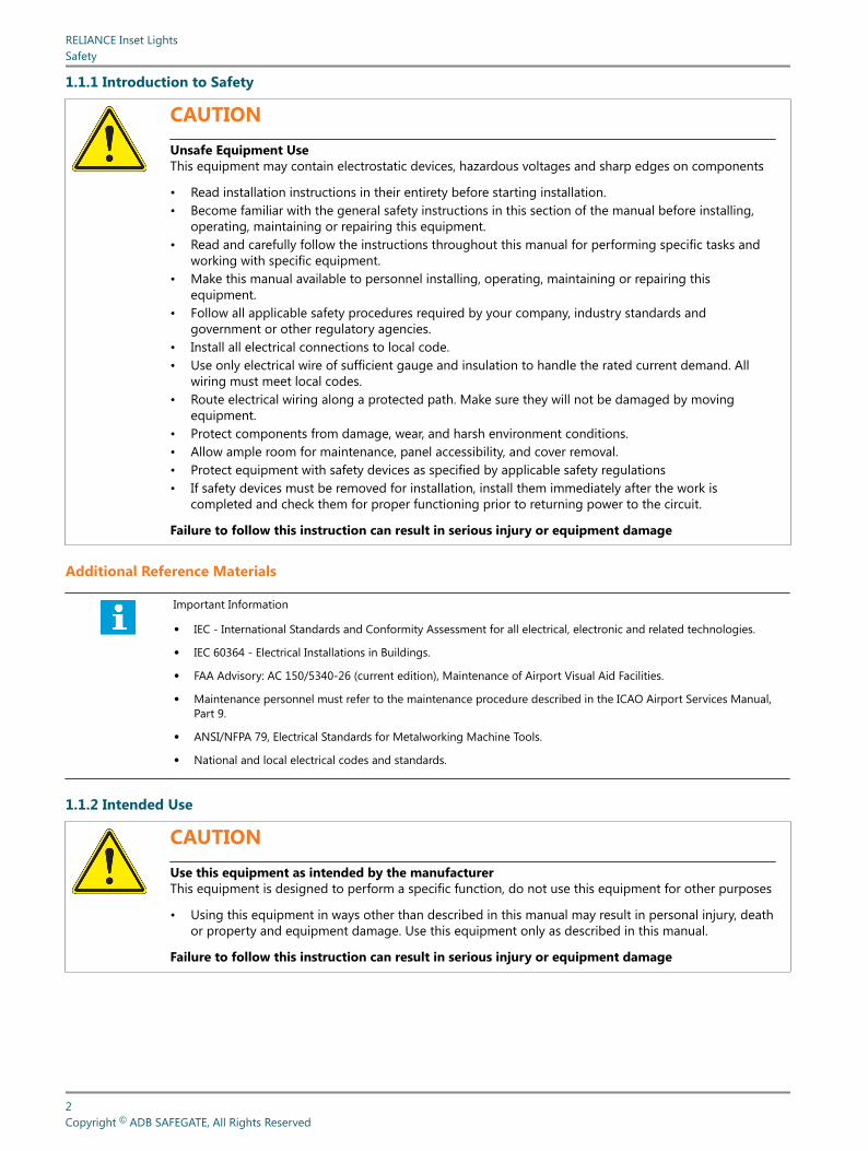
1.1.1 Introduction to Safety
CAUTIONUnsafe Equipment UseThis equipment may contain electrostatic devices, hazardous voltages and sharp edges on components
• Read installation instructions in their entirety before starting installation.• Become familiar with the general safety instructions in this section of the manual before installing,
operating, maintaining or repairing this equipment.• Read and carefully follow the instructions throughout this manual for performing specific tasks and
working with specific equipment.• Make this manual available to personnel installing, operating, maintaining or repairing this
equipment.• Follow all applicable safety procedures required by your company, industry standards and
government or other regulatory agencies.• Install all electrical connections to local code.• Use only electrical wire of sufficient gauge and insulation to handle the rated current demand. All
wiring must meet local codes.• Route electrical wiring along a protected path. Make sure they will not be damaged by moving
equipment.• Protect components from damage, wear, and harsh environment conditions.• Allow ample room for maintenance, panel accessibility, and cover removal.• Protect equipment with safety devices as specified by applicable safety regulations• If safety devices must be removed for installation, install them immediately after the work is
completed and check them for proper functioning prior to returning power to the circuit.
Failure to follow this instruction can result in serious injury or equipment damage
Additional Reference Materials
Important Information
• IEC - International Standards and Conformity Assessment for all electrical, electronic and related technologies.
• IEC 60364 - Electrical Installations in Buildings.
• FAA Advisory: AC 150/5340-26 (current edition), Maintenance of Airport Visual Aid Facilities.
• Maintenance personnel must refer to the maintenance procedure described in the ICAO Airport Services Manual,Part 9.
• ANSI/NFPA 79, Electrical Standards for Metalworking Machine Tools.
• National and local electrical codes and standards.
1.1.2 Intended Use
CAUTIONUse this equipment as intended by the manufacturerThis equipment is designed to perform a specific function, do not use this equipment for other purposes
• Using this equipment in ways other than described in this manual may result in personal injury, deathor property and equipment damage. Use this equipment only as described in this manual.
Failure to follow this instruction can result in serious injury or equipment damage
RELIANCE Inset LightsSafety
2Copyright © ADB SAFEGATE, All Rights Reserved

1.1.3 Material Handling Precautions: Storage
CAUTIONImproper StorageStore this equipment properly
• If equipment is to be stored prior to installation, it must be protected from the weather and kept freeof condensation and dust.
Failure to follow this instruction can result in equipment damage
1.1.4 Operation Safety
CAUTIONImproper OperationDo Not Operate this equipment other than as specified by the manufacturer
• Only qualified personnel, physically capable of operating the equipment and with no impairments intheir judgment or reaction times, should operate this equipment.
• Read all system component manuals before operating this equipment. A thorough understanding ofsystem components and their operation will help you operate the system safely and efficiently.
• Before starting this equipment, check all safety interlocks, fire-detection systems, and protectivedevices such as panels and covers. Make sure all devices are fully functional. Do not operate thesystem if these devices are not working properly. Do not deactivate or bypass automatic safetyinterlocks or locked-out electrical disconnects or pneumatic valves.
• Protect equipment with safety devices as specified by applicable safety regulations.• If safety devices must be removed for installation, install them immediately after the work is
completed and check them for proper functioning.• Route electrical wiring along a protected path. Make sure they will not be damaged by moving
equipment.• Never operate equipment with a known malfunction.• Do not attempt to operate or service electrical equipment if standing water is present.• Use this equipment only in the environments for which it is rated. Do not operate this equipment
in humid, flammable, or explosive environments unless it has been rated for safe operation in theseenvironments.
• Never touch exposed electrical connections on equipment while the power is ON.
Failure to follow these instructions can result in equipment damage
1.1.5 Maintenance Safety
DANGERElectric Shock HazardThis equipment may contain electrostatic devices
• Do not operate a system that contains malfunctioning components. If a component malfunctions,turn the system OFF immediately.
• Disconnect and lock out electrical power.• Allow only qualified personnel to make repairs. Repair or replace the malfunctioning component
according to instructions provided in its manual.
Failure to follow these instructions can result in death or equipment damage
UM-0211, Rev. 4.0, 2022/02/08 3Copyright © ADB SAFEGATE, All Rights Reserved

1.1.6 Material Handling Precautions: Fasteners
DANGERForeign Object Damage - FODThis equipment may contain fasteners that may come loose - torque properly.
• Only use fasteners of the same type as the one originally supplied with the equipment.• Use of incorrect combination of gaskets, bolts and nuts can create severe damages to the product
installation and create safety risk .• You need to know what base the light fixture will be installed in, in order to chose the correct gasket,
bolts and nuts.• Bolt type, length, and torque value are determined by type of base, height of spacers used, and clamp
force required in FAA Engineering Brief No 83 (latest revision).• Due to the risk of bolts vibrating loose, do not use any type of washer with the fixing bolts (such as
split lock washers) other than an anti-vibration washer. Anti-vibration washers as defined in FAA EB83 (latest edition) must be used. For installations other than FAA, use the base can manufacturer'srecommendations.
• Always tighten the fasteners to the recommended torque. Use a calibrated torque wrench and applythe recommended adhesive type.
• Obey the instructions of the adhesives necessary for the fasteners.
Failure to follow these warnings may cause the fasteners to loosen, damage the equipment,potentially to loosen the equipment. This can lead to a highly dangerous situation of FOD, withpotential lethal consequences.
NoteTo minimize the risk of errors, the ADB SAFEGATE Sales Representative will have information on which gasket goeswith which base. This information is also provided in the product Data sheets, the User Manuals and the Spare PartLists.
CAUTIONUse of incorrect combination of gaskets, bolts and nuts can create severe damages to the product installation andcreate multiple safety risks.To obtain a safe and watertight installation the O-ring and retaining bolt stated in the document must be used.You need to know what base the light fixture will be installed in, in order to choose the correct gasket, bolts and nuts.Failure to follow these cautions can result in equipment damage or aircraft FOD.
1.1.7 Material Handling Precautions, ESD
CAUTIONElectrostatic Sensitive DevicesThis equipment may contain electrostatic devices
• Protect from electrostatic discharge.• Electronic modules and components should be touched only when this is unavoidable e.g. soldering,
replacement.• Before touching any component of the cabinet you shall bring your body to the same potential as the
cabinet by touching a conductive earthed part of the cabinet.• Electronic modules or components must not be brought in contact with highly insulating materials
such as plastic sheets, synthetic fiber clothing. They must be laid down on conductive surfaces.• The tip of the soldering iron must be grounded.• Electronic modules and components must be stored and transported in conductive packing.
Failure to follow this instruction can result in equipment damage
RELIANCE Inset LightsSafety
4Copyright © ADB SAFEGATE, All Rights Reserved
2.0 About this Manual
This document includes RELIANCE™ inset light fixture information with a focus on safety, installation and maintenanceprocedures.
For more information, see www.adbsafegate.com.
NoteIt is very important to read this document before any work is started.
This manual covers the following 8-inch RELIANCE fixtures:
• Runway Centerline L-850A(L) (RC-I)
• Runway Touchdown Zone L-850B(L) (RZ-I)
• Rapid Exit Taxiway Indicator (RX-I)
• Taxiway Centerline Narrow L-852C(L) (TC-I)
• Taxiway Centerline Curve L-852K(L) (TC-I)
• Taxiway Centerline Wide (TC-I)
• Taxiway Centerline/Lead-On L-852D(L) (TC-I)
• ICAO Stop Bar (SB-I)
• FAA Stop Bar (L-852S(L)
2.1 Abbreviations and Terms
This document may include the abbreviations and terms listed below.
Abbreviation and term Description
A-SMGCS Advanced Surface Movement Guidance and Control System
CAA Civil Aviation Authority
CCR Constant Current Regulator
FAA Federal Aviation Administration
ICAO International Civil Aviation Organization
IEC International Electrotechnical Committee
ILCMS Individual Light Control and Monitoring System
LED Light Emitting Diode
NATO North Atlantic Treaty Organization
SMGCS Surface Movement Guidance and Control System
SSU System Switch Unit
STAC Service Technique de l'Aviation Civile (France)
STANAG Standardization Agreement (NATO)
UM-0211, Rev. 4.0, 2022/02/08 5Copyright © ADB SAFEGATE, All Rights Reserved
RELIANCE Inset LightsAbout this Manual
6Copyright © ADB SAFEGATE, All Rights Reserved

3.0 Introduction
RELIANCE - the all in one revolution
The RELIANCE inset light is a bi- or unidirectional low protrusion light-emitting diode (LED) fixture, available in three versions:
RELIANCE A LED light fixture with integrated fail open technology with CCR monitoringcompatibility
RELIANCE IQ A RELIANCE with additional and integrated intelligence (IQ) in a built-in converter forindividual monitoring and control, based on RELIANCE Intelligent Light Control andMonitor System (ILCMS)
RELIANCE IQ0 RELIANCE IQ light fixture with disabled IQ (ILCMS) functionality. Non-MON light fixturewith possibility to activate IQ at a later stage
NoteRELIANCE IQ light fixtures are not fail-open light fixtures. When IQ is activated the monitoring as well as the controlfunctionality is handled by the ILCMS system.
3.1 Product Information
Compliance and Standards
Compliance Description Application: RC-RZ-RX TC SB
Reference DS-XXXX: 0167 0209 0199
FAA AC 150/5345-46 and the FAA Engineering Brief No. 67 X X X
ICAO Annex 14 Volume 1 X X X
EASA CS-ADR-DSN X X X
Australia MOS 139 X X X
Canada TP 312 X X X
IEC 61827 X X X
NATO STANAG 3316 X X X
STAC PRO/STAC/SE/VIS X X X
X X X
Features and Benefits
Efficiency • Available in three versions:
• RELIANCE™ IQ with integrated intelligence
• RELIANCE with integrated fail-open (Mon) technology. Fuse resistors are part of the Mon-functionality and spares needsto be ordered separately.
• RELIANCE Non-MON, non-monitored lights
• Light Emitting Diode (LED) technology that offers a long-lasting light source with low power consumption
UM-0211, Rev. 4.0, 2022/02/08 7Copyright © ADB SAFEGATE, All Rights Reserved
• Compatibility between RELIANCE IQ version and RELIANCE Intelligent Lighting 2A system for further power savings andILCMS
• No visual flicker. PWM is used for some applications to optimize the LED performance and light fixtures show no visualflickering.
Sustainability • Fully encapsulated all-in-one electronics
• IP68 protected, aluminum housing designed for harsh weather environments, all fastenings in stainless steel
• Reinforced prism available as an option
• Operates on 3- or 5-step ferroresonant or thyristor CCRs designed in compliance with IEC or FAA requirements
• Easy handling and maintenance by modular design with few mechanical parts
• Compatible with existing infrastructure
Safety • Built-in voltage surge and lightning protection
• Fully dimmable lights, respecting the response curve of traditional halogen lights
• Low protrusion, high-intensity, Style 3 inset light fixtures
• No negative slope in front of the prisms
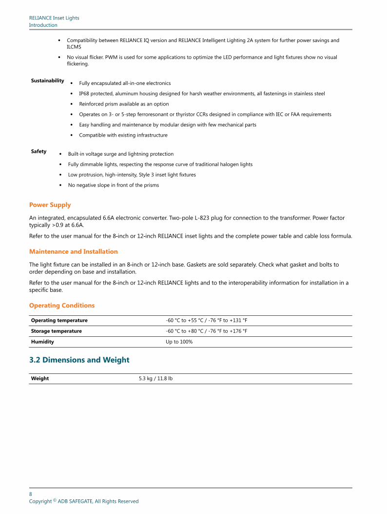
Power Supply
An integrated, encapsulated 6.6A electronic converter. Two-pole L-823 plug for connection to the transformer. Power factortypically >0.9 at 6.6A.
Refer to the user manual for the 8‑inch or 12‑inch RELIANCE inset lights and the complete power table and cable loss formula.
Maintenance and Installation
The light fixture can be installed in an 8‑inch or 12‑inch base. Gaskets are sold separately. Check what gasket and bolts toorder depending on base and installation.
Refer to the user manual for the 8‑inch or 12‑inch RELIANCE lights and to the interoperability information for installation in aspecific base.
Operating Conditions
Operating temperature -60 °C to +55 °C / -76 °F to +131 °F
Storage temperature -60 °C to +80 °C / -76 °F to +176 °F
Humidity Up to 100%
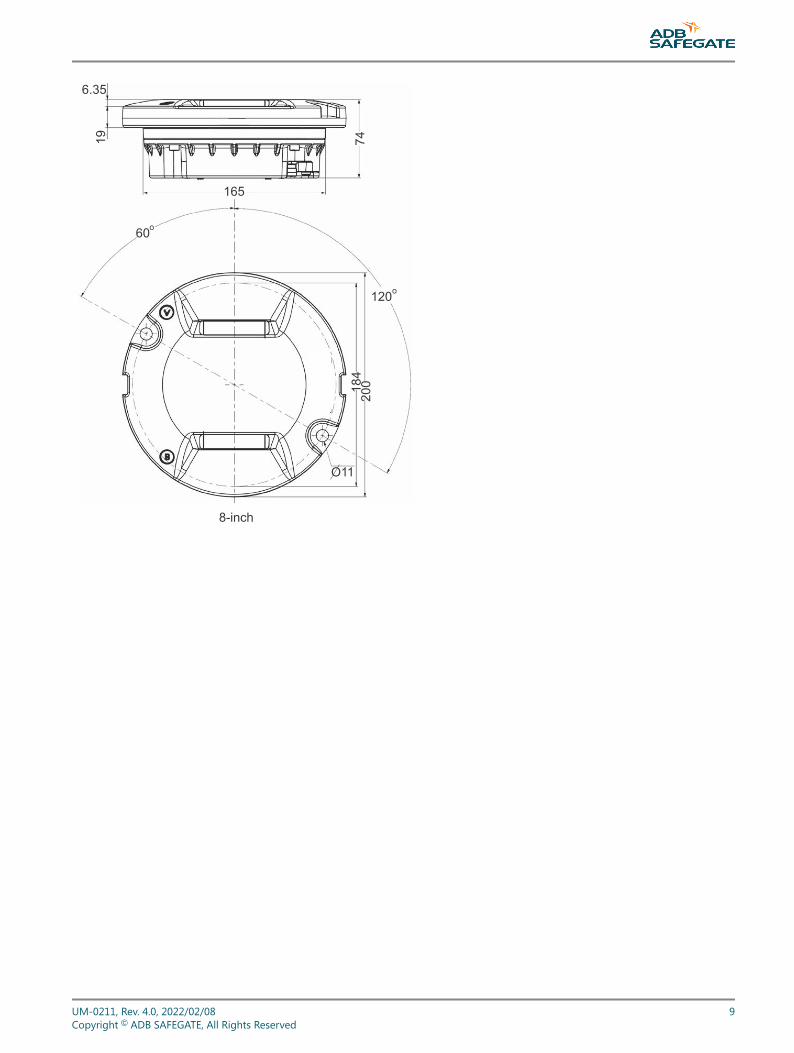
3.2 Dimensions and Weight
Weight 5.3 kg / 11.8 lb
RELIANCE Inset LightsIntroduction
8Copyright © ADB SAFEGATE, All Rights Reserved
196.35
74
165
60o
120o
O11
148
200
8-inch
UM-0211, Rev. 4.0, 2022/02/08 9Copyright © ADB SAFEGATE, All Rights Reserved
RELIANCE Inset LightsIntroduction
10Copyright © ADB SAFEGATE, All Rights Reserved
4.0 Installation
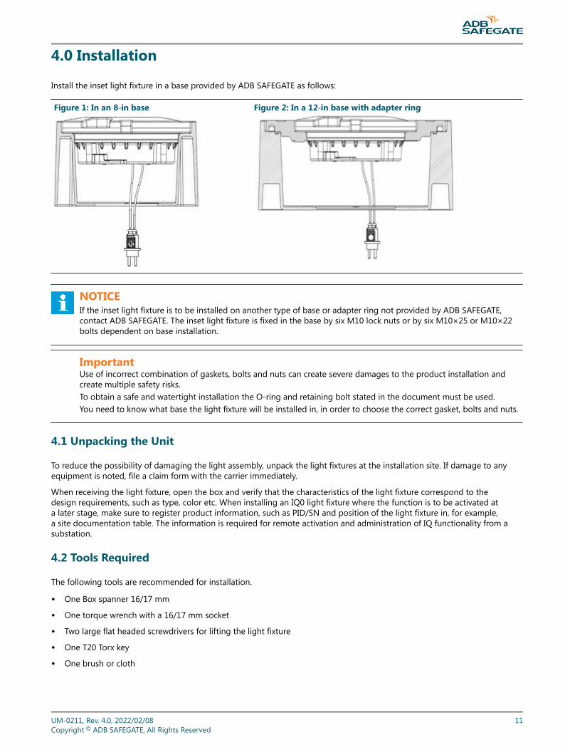
Install the inset light fixture in a base provided by ADB SAFEGATE as follows:
Figure 1: In an 8‑in base Figure 2: In a 12‑in base with adapter ring
NOTICEIf the inset light fixture is to be installed on another type of base or adapter ring not provided by ADB SAFEGATE,contact ADB SAFEGATE. The inset light fixture is fixed in the base by six M10 lock nuts or by six M10×25 or M10×22bolts dependent on base installation.
ImportantUse of incorrect combination of gaskets, bolts and nuts can create severe damages to the product installation andcreate multiple safety risks.To obtain a safe and watertight installation the O-ring and retaining bolt stated in the document must be used.You need to know what base the light fixture will be installed in, in order to choose the correct gasket, bolts and nuts.
4.1 Unpacking the Unit
To reduce the possibility of damaging the light assembly, unpack the light fixtures at the installation site. If damage to anyequipment is noted, file a claim form with the carrier immediately.
When receiving the light fixture, open the box and verify that the characteristics of the light fixture correspond to thedesign requirements, such as type, color etc. When installing an IQ0 light fixture where the function is to be activated ata later stage, make sure to register product information, such as PID/SN and position of the light fixture in, for example,a site documentation table. The information is required for remote activation and administration of IQ functionality from asubstation.
4.2 Tools Required
The following tools are recommended for installation.
• One Box spanner 16/17 mm
• One torque wrench with a 16/17 mm socket
• Two large flat headed screwdrivers for lifting the light fixture
• One T20 Torx key
• One brush or cloth
UM-0211, Rev. 4.0, 2022/02/08 11Copyright © ADB SAFEGATE, All Rights Reserved
NOTICEProvided that the base intended to receive the light fixture has been properly installed, no other specific tool isrequired.
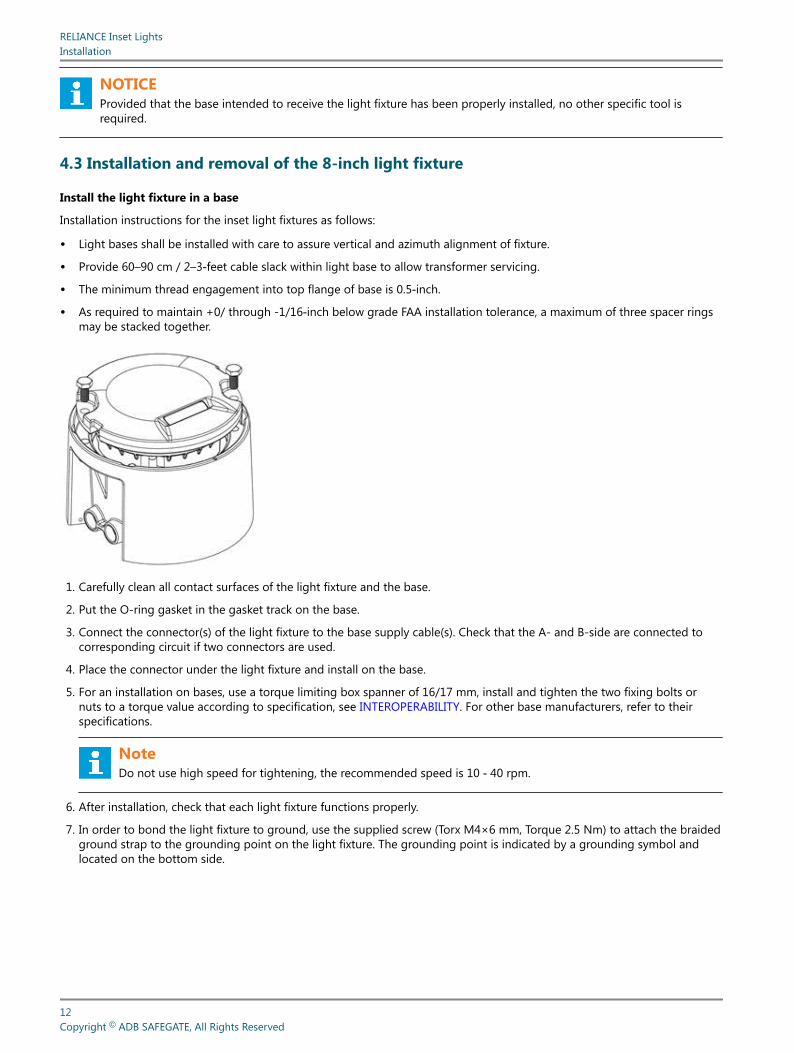
4.3 Installation and removal of the 8-inch light fixture
Install the light fixture in a base
Installation instructions for the inset light fixtures as follows:
• Light bases shall be installed with care to assure vertical and azimuth alignment of fixture.
• Provide 60–90 cm / 2–3‑feet cable slack within light base to allow transformer servicing.
• The minimum thread engagement into top flange of base is 0.5‑inch.
• As required to maintain +0/ through -1/16‑inch below grade FAA installation tolerance, a maximum of three spacer ringsmay be stacked together.
1. Carefully clean all contact surfaces of the light fixture and the base.
2. Put the O-ring gasket in the gasket track on the base.
3. Connect the connector(s) of the light fixture to the base supply cable(s). Check that the A- and B-side are connected tocorresponding circuit if two connectors are used.
4. Place the connector under the light fixture and install on the base.
5. For an installation on bases, use a torque limiting box spanner of 16/17 mm, install and tighten the two fixing bolts ornuts to a torque value according to specification, see INTEROPERABILITY. For other base manufacturers, refer to theirspecifications.
NoteDo not use high speed for tightening, the recommended speed is 10 ‑ 40 rpm.
6. After installation, check that each light fixture functions properly.
7. In order to bond the light fixture to ground, use the supplied screw (Torx M4×6 mm, Torque 2.5 Nm) to attach the braidedground strap to the grounding point on the light fixture. The grounding point is indicated by a grounding symbol andlocated on the bottom side.
RELIANCE Inset LightsInstallation
12Copyright © ADB SAFEGATE, All Rights Reserved

Remove the fitting from the base
CAUTIONFall- and trip hazard! When a light fixture has been removed, the base must be fitted with a cover designed for thispurpose or with a spare light fixture.
1. Remove the light fixture from the base using two large flat blade screwdrivers.
2. Disconnect the secondary supply connector.
3. Remove and check the gasket (O-ring or labyrinth).
NoteIt is recommended to change the gasket, lock nuts or bolts each time the light fixture is removed or dismounted fromthe base. For more information, see INTEROPERABILITY.
CAUTIONUse of incorrect combination of gaskets, bolts and nuts can create severe damages to the product installation andcreate multiple safety risks.Make sure to know what base the light fixture will be installed in, in order to chose the correct gasket, bolts and nuts.Failure to follow these cautions can result in equipment damage or aircraft FOD. For more information, seeINTEROPERABILITY.
4.4 Toe-in
Toe-in of light fixtures can be achieved in two ways:
1. By installing the light fixture in runway/taxiway parallel bases and use light fixtures with built in toe-in.
2. By installing the light fixture in bases installed at an angle relative the runway/taxiway and use light fixtures with no builtin toe-in.
If bases which are installed at an angle are used, provided that they are installed correctly, straight light fixtures (i.e. with notoe-in) should be used.
The following chapter only regards the case where light fixtures are installed in runway/taxiway parallel bases, i.e. where notoe-in is achieved by angled bases.
There are three major categories regarding the toe-in in light fixtures:
Straight light fixtures These light fixtures have a straight light beam
Light fixtures with optical toe-in These light fixtures have a reflector that reflects the light beam at an appropriate angle
Light fixtures with mechanical toe-in These light fixtures are installed at an angle with in its base due to the hole pattern for thebase screws. This results in an angled light beam relative to the runway/taxiway.
Figure 3: Toe-in
Straight Optical Toe-in Mechanical Toe-in
Prism direction
Lightbeamdirection
UM-0211, Rev. 4.0, 2022/02/08 13Copyright © ADB SAFEGATE, All Rights Reserved
The table below shows a summary of the light fixture types and their toe-in properties.
Light Fixture Toe-in options Toe-in type
L-850A(L) - Runway Centreline (RC-I) Straight N/A
L-850B(L) - Runway Touchdown Zone (RZ-I) Straight or Toe-in ±4° Mechanical
Rapid Exit Taxiway Indicator (RX-I) Straight N/A
L-852C(L) - Taxiway Centreline Narrow (TC-I) Straight N/A
L-852K(L) - Taxiway Centreline Curve (TC-I) ±15.75˚ Optical
Taxiway Centreline Wide (TC-I) Straight N/A
L-852D(L) - Taxiway Centreline/Lead-On (TC-I) Straight N/A
L-852S(L) & ICAO Stop Bar (SB-I) Straight or Toe-in ±15.75˚ Optical
4.5 Light Emission Directions
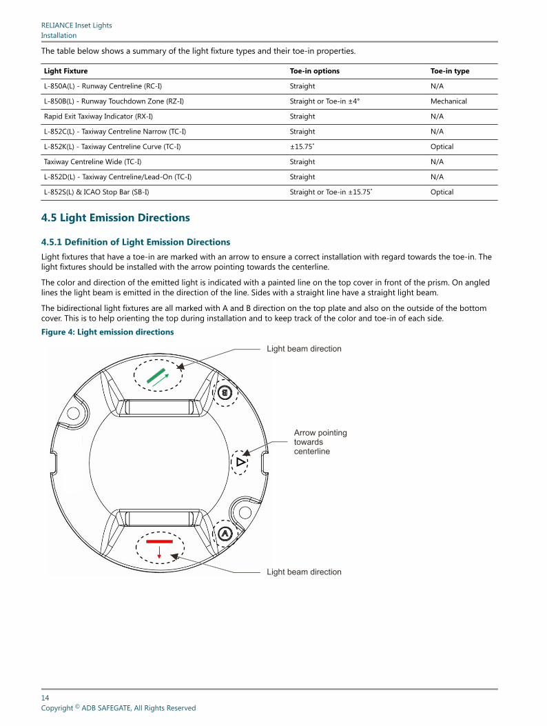
4.5.1 Definition of Light Emission DirectionsLight fixtures that have a toe-in are marked with an arrow to ensure a correct installation with regard towards the toe-in. Thelight fixtures should be installed with the arrow pointing towards the centerline.
The color and direction of the emitted light is indicated with a painted line on the top cover in front of the prism. On angledlines the light beam is emitted in the direction of the line. Sides with a straight line have a straight light beam.
The bidirectional light fixtures are all marked with A and B direction on the top plate and also on the outside of the bottomcover. This is to help orienting the top during installation and to keep track of the color and toe-in of each side.
Figure 4: Light emission directions
Light beam direction
Light beam direction
Arrow pointingtowardscenterline
RELIANCE Inset LightsInstallation
14Copyright © ADB SAFEGATE, All Rights Reserved

4.5.2 RELIANCE IQ0 and RELIANCE IQ1 Schematic Installation ExampleIt is important to keep track of the positioning of the RELIANCE IQ0 and RELIANCE IQ1 light fixtures in the bases in order toprogram the RELIANCE Intelligent Lighting parameters correctly.
Figure 5: Schematic installation example
A B A B A BA BA BA BA BB AB AB A
B B
B B
BB
BB
4.5.3 8-inch Light Beam TypesThe inset Taxiway centerline and Stop Bar light fixtures have different light beam characteristics depending on application. Thelight beam can be narrow, wide or curved. The drawings below show the different types of light beam, which correspond tothe different type of fitting.
NoteIn order to assist with the installation of the fitting in its base in curved sections, make sure that the top of the fittingmarked with an arrow always point to the center of the curve.
Table 1: Bidirectional light beamSTRAIGHT TOE-IN
Narrow Wide Wide Curved
ICAO Fig A2-13 ICAO Fig A2-12
FAA L852C(L) FAA L852D(L) FAA L852K(L)
UM-0211, Rev. 4.0, 2022/02/08 15Copyright © ADB SAFEGATE, All Rights Reserved
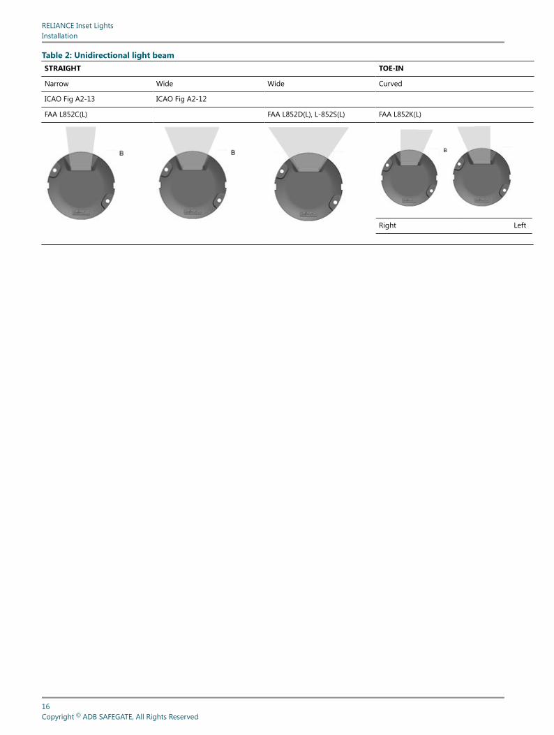
Table 2: Unidirectional light beamSTRAIGHT TOE-IN
Narrow Wide Wide Curved
ICAO Fig A2-13 ICAO Fig A2-12
FAA L852C(L) FAA L852D(L), L-852S(L) FAA L852K(L)
Right Left
RELIANCE Inset LightsInstallation
16Copyright © ADB SAFEGATE, All Rights Reserved
5.0 Operation
NoteRefer to the UM-0600 and other documentation related to RELIANCE IL I and listed with ordering numbers in Datasheet DS-0600 for further info.
UM-0211, Rev. 4.0, 2022/02/08 17Copyright © ADB SAFEGATE, All Rights Reserved

RELIANCE Inset LightsOperation
18Copyright © ADB SAFEGATE, All Rights Reserved

6.0 Maintenance
This section describes different steps for maintenance of the light fixture.
Before you start, make sure you have read and understand Safety instructions.
Find out the location of the light unit that needs maintenance. If the purpose is to replace an existing light unit with new one,make sure that corresponding unit is available. Find the type information on the identification tag with details of name.
Spare parts are available, if required. For more information, see www.adbsafegate.com and the Spare Parts List document, orcontact ADB SAFEGATE for assistance.
CAUTIONUse of incorrect combination of gaskets, bolts and nuts can create severe damages to the product installation andcreate multiple safety risks.You need to know what base the light fixture will be installed in, in order to chose the correct gasket, bolts and nuts.Failure to follow these cautions can result in equipment damage or aircraft FOD. For more information, seeINTEROPERABILITY.
CAUTIONWhen a light fixture has been removed from its base, the base must be either fitted with a cover or a spare light fixtureput in its place. It is recommended that only authorized personnel disassemble fittings with prior agreement fromADB SAFEGATE.
6.1 Basic Maintenance Program
There are recommended maintenance tasks to ensure that the equipment is in correct operating condition.
Maintenance tasks
Weekly • Visual inspection of the light fixture.
• Removal of dust from external surfaces of the light fixture.
Monthly • Check of the optical window, check for mechanical damage.
• Check for proper fixing of the light fixture in its base.
Yearly • Detailed inspection of the light fixture.
• Check of the body resistance, check for mechanical damage (for example cracks around prism windows).
• Clean of the optical windows.
A daily function check is referred to in the document:ICAO, Airport Services Manual Part 9, Airport Maintenance Practice and FAA AC 150/5340-26A,Maintenance of airport visual aids facilities.
The light fixture is designed for outdoor operation, however storing the light fixture outside without using it is a risk fordamage to light fixture components. For a longer storage time (more than a week), it is recommended to store the lightfixture indoors in a dry and dust free environment and at room temperature. Proper storage ensures trouble free replacementprocedures. It is strongly recommended not to store any electrical equipment outside.
UM-0211, Rev. 4.0, 2022/02/08 19Copyright © ADB SAFEGATE, All Rights Reserved
6.2 Workshop Maintenance
CAUTIONBefore you start, make sure you have read and understand Safety instructions.
The following standard tools and accessories are required for maintenance of the unit:
• One angled socket spanner of 16 or 17 mm 1
• One Torque limiting spanner with 16 or 17 mm socket 1
• One hexagonal key (Allen key) of 3, 4, and 5 mm
• Torx 10, 20, 25, and 30
• Two large flat blade screwdrivers
• Silicone grease
• CC-Patron grease
• One brush or cloth
• Non-alcohol based cleaner
NoteA compressor, or a manual car tire pump, equipped with a manometer is required to check the light fixture forwater-tightness.Design may differ from picture depending on application. Please follow described work flow and torque level specifiedas they are generic.
The workshop maintenance refers to following:
1. Replace a light fixture
2. Check the light fixture for water-tightness
3. Replace a light engine
4. Replace a prism and its gasket
5. Replace the bottom cover and converter
6. Reset the fail-open converter
1 Depending on type and size of nuts and bolts
RELIANCE Inset LightsMaintenance
20Copyright © ADB SAFEGATE, All Rights Reserved
6.2.1 Open and close an 8‑inch FixtureRemove
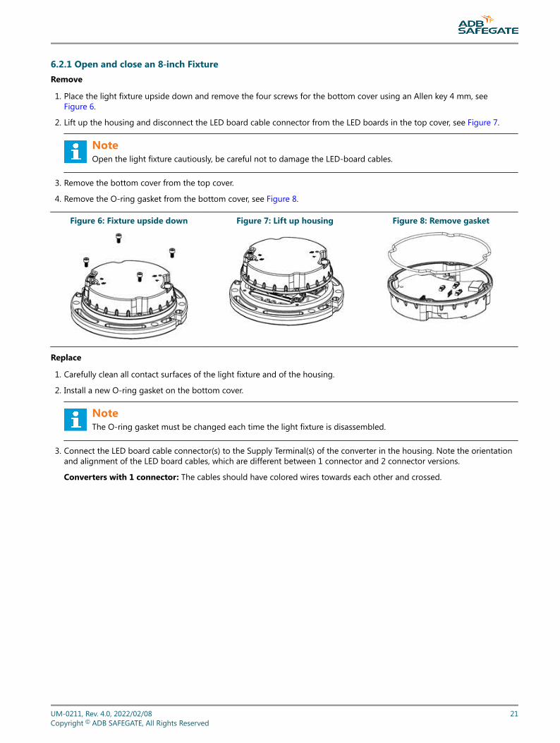
1. Place the light fixture upside down and remove the four screws for the bottom cover using an Allen key 4 mm, seeFigure 6.
2. Lift up the housing and disconnect the LED board cable connector from the LED boards in the top cover, see Figure 7.
NoteOpen the light fixture cautiously, be careful not to damage the LED-board cables.
3. Remove the bottom cover from the top cover.
4. Remove the O-ring gasket from the bottom cover, see Figure 8.
Figure 6: Fixture upside down Figure 7: Lift up housing Figure 8: Remove gasket
Replace
1. Carefully clean all contact surfaces of the light fixture and of the housing.
2. Install a new O-ring gasket on the bottom cover.
NoteThe O-ring gasket must be changed each time the light fixture is disassembled.
3. Connect the LED board cable connector(s) to the Supply Terminal(s) of the converter in the housing. Note the orientationand alignment of the LED board cables, which are different between 1 connector and 2 connector versions.
Converters with 1 connector: The cables should have colored wires towards each other and crossed.
UM-0211, Rev. 4.0, 2022/02/08 21Copyright © ADB SAFEGATE, All Rights Reserved
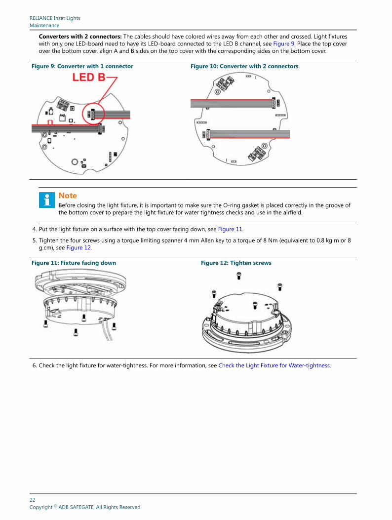
Converters with 2 connectors: The cables should have colored wires away from each other and crossed. Light fixtureswith only one LED-board need to have its LED-board connected to the LED B channel, see Figure 9. Place the top coverover the bottom cover, align A and B sides on the top cover with the corresponding sides on the bottom cover.
Figure 9: Converter with 1 connector Figure 10: Converter with 2 connectors
NoteBefore closing the light fixture, it is important to make sure the O-ring gasket is placed correctly in the groove ofthe bottom cover to prepare the light fixture for water tightness checks and use in the airfield.
4. Put the light fixture on a surface with the top cover facing down, see Figure 11.
5. Tighten the four screws using a torque limiting spanner 4 mm Allen key to a torque of 8 Nm (equivalent to 0.8 kg m or 8g.cm), see Figure 12.
Figure 11: Fixture facing down Figure 12: Tighten screws
6. Check the light fixture for water-tightness. For more information, see Check the Light Fixture for Water-tightness.
RELIANCE Inset LightsMaintenance
22Copyright © ADB SAFEGATE, All Rights Reserved

6.2.2 Check the Light Fixture for Water-tightnessIf maintenance is carried out in a workshop, check the water-tightness of the light.
Prepare
1. Remove the water-tightness test valve cap.
2. Fill up the light fixture with compressed air (test pressure = 130 kPa).
Test
1. Put the light fixture in water, wait 3 minutes and check if air leaks out of the light.
a. If air leaks out of the light fixture (between bottom cover and top plate or between prism and top plate or water-tightness valve and top plate), the light fixture is not watertight and must be repaired. Release the air from the light.Disassemble the light fixture and re-check the mating surfaces and gaskets. Assemble the light fixture and perform thewater-tightness test again.
b. If the light fixture is water tight, release the compressed air from the light fixture and assemble the cap on the testvalve.
2. The light fixture is ready to be reinstalled in the field.
DANGERNever exceed pressure of 150 kPa inside the light fixture as this may lead to personal injuries and damage the light.
UM-0211, Rev. 4.0, 2022/02/08 23Copyright © ADB SAFEGATE, All Rights Reserved
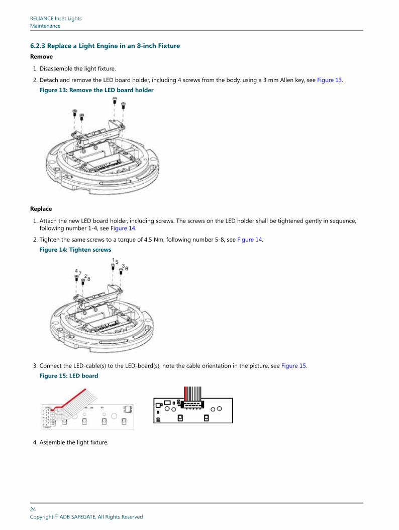
6.2.3 Replace a Light Engine in an 8‑inch FixtureRemove
1. Disassemble the light fixture.
2. Detach and remove the LED board holder, including 4 screws from the body, using a 3 mm Allen key, see Figure 13.
Figure 13: Remove the LED board holder
Replace
1. Attach the new LED board holder, including screws. The screws on the LED holder shall be tightened gently in sequence,following number 1-4, see Figure 14.
2. Tighten the same screws to a torque of 4.5 Nm, following number 5-8, see Figure 14.
Figure 14: Tighten screws
3. Connect the LED-cable(s) to the LED-board(s), note the cable orientation in the picture, see Figure 15.
Figure 15: LED board
4. Assemble the light fixture.
RELIANCE Inset LightsMaintenance
24Copyright © ADB SAFEGATE, All Rights Reserved

6.2.4 Replace a Prism and its Gasket in an 8‑inch FixtureRemove
1. Disassemble the light fixture.
2. Detach and remove the LED board holder, including 4 screws from the body, using a 3 mm Allen key. See Figure 16.
3. Remove the Teflon and steel protective plates from the LED board holder.
4. Remove the prism and its gasket, see Figure 17.
Figure 16: Remove LED board holder Figure 17: Remove prism and gasket
Replace
1. Lubricate the new prism gasket with CC Patron grease.
2. Place the prism gasket in the prism opening in the top cover.
3. Put the new prism into the new prism gasket, then push it all the way into the opening and hold for about a minute. SeeFigure 18.
Figure 18: New prism into prism gasket
4. Check that the O-ring of the prism gasket is even in the chambered area.
5. Place the new Teflon protective plate and steel plate over the prism and prism gasket and tighten the two M4 screws to atorque of 4.5 Nm.
UM-0211, Rev. 4.0, 2022/02/08 25Copyright © ADB SAFEGATE, All Rights Reserved

6. Looking from above, make sure the prism edge is parallel with the prism holder, see Figure 19.
Figure 19: Prism holder edge
7. Use alcohol based cleaner to remove any grease or dust from the prism.
8. Attach the LED board holder, including screws. The screws on the LED holder shall be tightened to a torque of 4.5 Nm, insequence 1-4. Tighten the same screws again to a torque of 4.5 Nm, in sequence 5-8. See Figure 20.
NoteThe torquing sequence must be respected as it ensures correct positioning of the prism.
Figure 20: Tighten screws in sequence
2
4 1
35
6
78
9. Re-tighten the two screws on the steel plate to 4.5 Nm. See Figure 20.
10. Assemble the light fixture.
11. Cut off any protruding prism gasket on the outside of the top cover.
RELIANCE Inset LightsMaintenance
26Copyright © ADB SAFEGATE, All Rights Reserved
6.2.5 Replace the Bottom Cover and ConverterRemove
1. Disassemble the light fixture.
2. From inside the housing, disconnect all cables from the LED board.
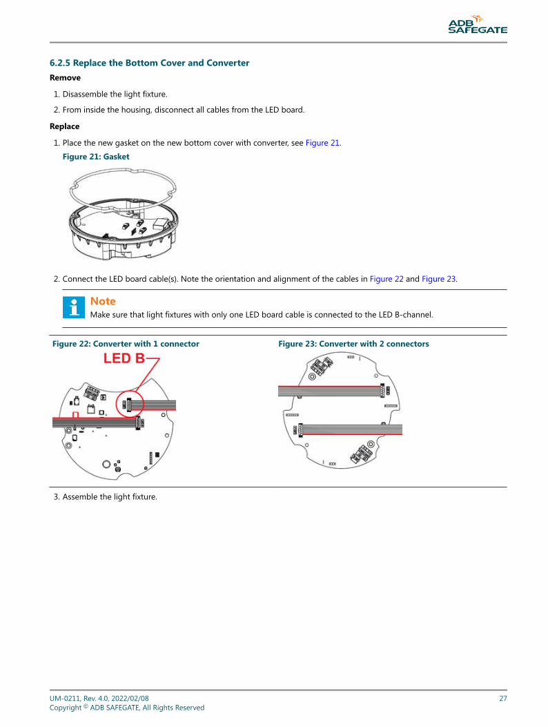
Replace
1. Place the new gasket on the new bottom cover with converter, see Figure 21.
Figure 21: Gasket
2. Connect the LED board cable(s). Note the orientation and alignment of the cables in Figure 22 and Figure 23.
NoteMake sure that light fixtures with only one LED board cable is connected to the LED B-channel.
Figure 22: Converter with 1 connector Figure 23: Converter with 2 connectors
3. Assemble the light fixture.
UM-0211, Rev. 4.0, 2022/02/08 27Copyright © ADB SAFEGATE, All Rights Reserved
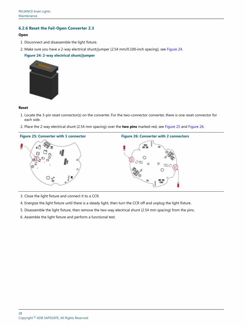
6.2.6 Reset the Fail-Open Converter 2.3Open
1. Disconnect and disassemble the light fixture.
2. Make sure you have a 2-way electrical shunt/jumper (2.54 mm/0.100‑inch spacing), see Figure 24.
Figure 24: 2-way electrical shunt/jumper
Reset
1. Locate the 3-pin reset connector(s) on the converter. For the two-connector converter, there is one reset connector foreach side.
2. Place the 2-way electrical shunt (2.54 mm spacing) over the two pins marked red, see Figure 25 and Figure 26.
Figure 25: Converter with 1 connector Figure 26: Converter with 2 connectors
3. Close the light fixture and connect it to a CCR.
4. Energize the light fixture until there is a steady light, then turn the CCR off and unplug the light fixture.
5. Disassemble the light fixture, then remove the two-way electrical shunt (2.54 mm spacing) from the pins.
6. Assemble the light fixture and perform a functional test.
RELIANCE Inset LightsMaintenance
28Copyright © ADB SAFEGATE, All Rights Reserved
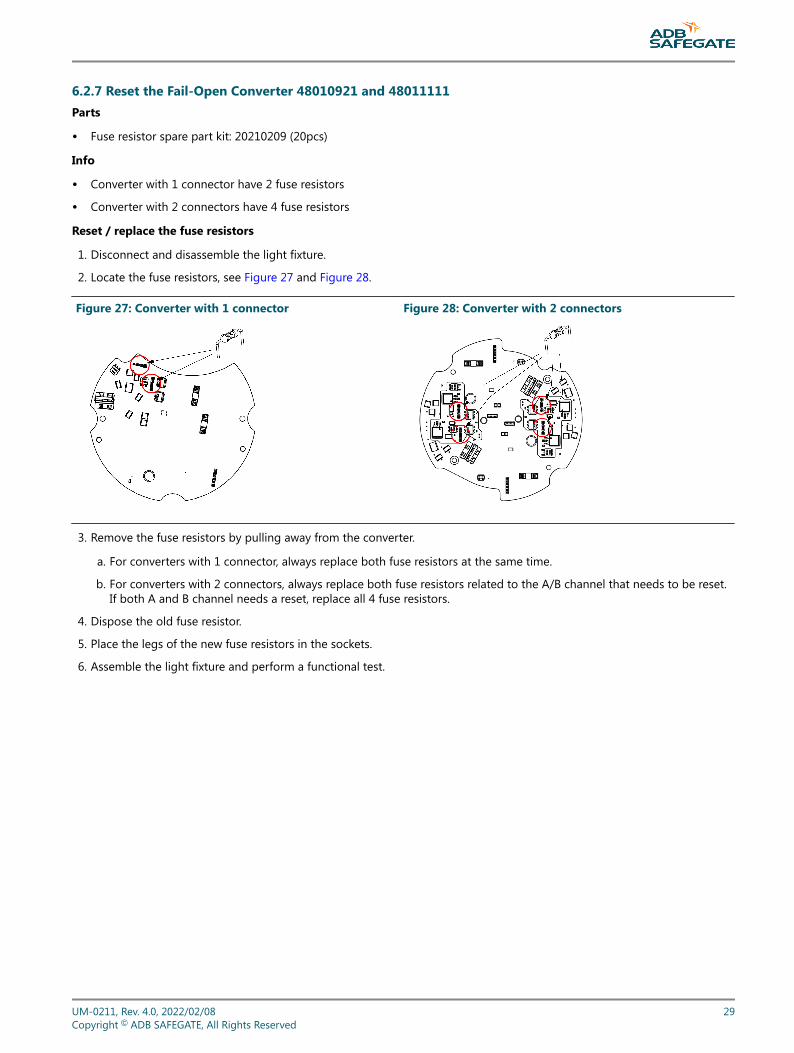
6.2.7 Reset the Fail-Open Converter 48010921 and 48011111Parts
• Fuse resistor spare part kit: 20210209 (20pcs)
Info
• Converter with 1 connector have 2 fuse resistors
• Converter with 2 connectors have 4 fuse resistors
Reset / replace the fuse resistors
1. Disconnect and disassemble the light fixture.
2. Locate the fuse resistors, see Figure 27 and Figure 28.
Figure 27: Converter with 1 connector Figure 28: Converter with 2 connectors
3. Remove the fuse resistors by pulling away from the converter.
a. For converters with 1 connector, always replace both fuse resistors at the same time.
b. For converters with 2 connectors, always replace both fuse resistors related to the A/B channel that needs to be reset.If both A and B channel needs a reset, replace all 4 fuse resistors.
4. Dispose the old fuse resistor.
5. Place the legs of the new fuse resistors in the sockets.
6. Assemble the light fixture and perform a functional test.
UM-0211, Rev. 4.0, 2022/02/08 29Copyright © ADB SAFEGATE, All Rights Reserved

RELIANCE Inset LightsMaintenance
30Copyright © ADB SAFEGATE, All Rights Reserved
7.0 Ordering Codes and Spare Parts
Spare parts are available for RELIANCE and RELIANCE IQ inset light fixtures. For more information, see www.adbsafegate.comand the spare part lists, or contact ADB SAFEGATE for assistance.
UM-0211, Rev. 4.0, 2022/02/08 31Copyright © ADB SAFEGATE, All Rights Reserved

7.1 Ordering Code (RC-RZ-RX)
Ordering Code ISApplicationRC = Runway Centerline L-850A(L)RZ = Touchdown zone L-850B (L)RX = RETILPrismS = Standard prismR = Reinforced prismDiameter1 = 8 in2 = 12 inTypeU = UnidirectionalB = BidirectionalToe-inS = StraightL = Left (for RZ only)R = Right (for RZ only)Options0 = No optionsColor – B SideW = WhiteR = RedY = YellowColor – A sideW = WhiteR = RedN = NonePower and MonitoringS = 2.8 - 6.6 A, without monitoring (Non-MON)M = 2.8 - 6.6 A, with monitoring (with fail-open)P = 2.8 - 6.6 A/ 2 A, IQ0 (IQ disabled)Q = 2.8 - 6.6 A/ 2 A, IQ1 (IQ enabled)StandardsI = ICAO only (RX)G = Global (RC, RZ)Cord set typeA = FAA Style 6 (2 - pin-) plugCable and connector2 = 1x 2-pin plug3 = 2x 2-pin plugsVersion3 = RELIANCE
RELIANCE Inset LightsOrdering Codes and Spare Parts
32Copyright © ADB SAFEGATE, All Rights Reserved
Note• Toe-in options only affect the touchdown zone L - 850B(L) fixtures
• The IQ functionality allows control and monitoring of the RELIANCE IQ. IQ1 fixtures are pre - configured for thespecific position at delivery. This function is disabled in IQ0 fixtures but could be enabled later. IQ light fixtures areonly available as a one connector option.
UM-0211, Rev. 4.0, 2022/02/08 33Copyright © ADB SAFEGATE, All Rights Reserved
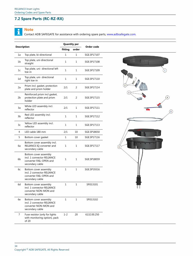
7.2 Spare Parts (RC-RZ-RX)
NoteContact ADB SAFEGATE for assistance with ordering spare parts, www.adbsafegate.com.
DescriptionQuantity per
Order codefitting order
1a Top plate, bi-directional 1 1 SGE.SP17107
1b Top plate, uni-directionalstraight 1 1 SGE.SP17108
1c Top plate, uni- directional lefttoe-in 1 1 SGE.SP17109
1d Top plate, uni- directionalright toe-in 1 1 SGE.SP17110
2a Prism incl. gasket, protectionplate and prism holder 2/1 2 SGE.SP17114
2bReinforced prism incl gasket,protection plate and prismholder
2/1 2 SGE.SP17115
3a White LED assembly incl.reflector 2/1 1 SGE.SP17111
3b Red LED assembly incl.reflector 1 1 SGE.SP17112
3c Yellow LED assembly incl.reflector 1 1 SGE.SP17113
4 LED cable 180 mm 2/1 10 SGE.SP18650
5 Bottom cover gasket 1 10 SGE.SP17116
6aBottom cover assembly incl.RELIANCE IQ converter andsecondary cable
1 1 SGE.SP17117
6b
Bottom cover assemblyincl. 1 connector RELIANCEconverter FAIL-OPEN andsecondary cable
1 1 SGE.SP18059
6c Bottom cover assemblyincl. 2 connector RELIANCEconverter FAIL-OPEN andsecondary cable
1 1 SGE.SP19316
6d Bottom cover assemblyincl. 1 connector RELIANCEconverter NON-MON andsecondary cable
1 1 SP.013101
6e Bottom cover assemblyincl. 2 connector RELIANCEconverter NON-MON andsecondary cable
1 1 SP.013102
7 Fuse resistor (only for lightswith monitoring option), packof 20
1-2 20 6132.00.250
RELIANCE Inset LightsOrdering Codes and Spare Parts
34Copyright © ADB SAFEGATE, All Rights Reserved
NoteAll screws for fastening are included.Component availability or design may be subject to change due to unforeseen circumstances. This document issubject to change or new information from ADB SAFEGATE, as and when available or if required, with reservation forerror or price changes.For more information contact ADB SAFEGATE, see www.adbsafegate.com.
UM-0211, Rev. 4.0, 2022/02/08 35Copyright © ADB SAFEGATE, All Rights Reserved
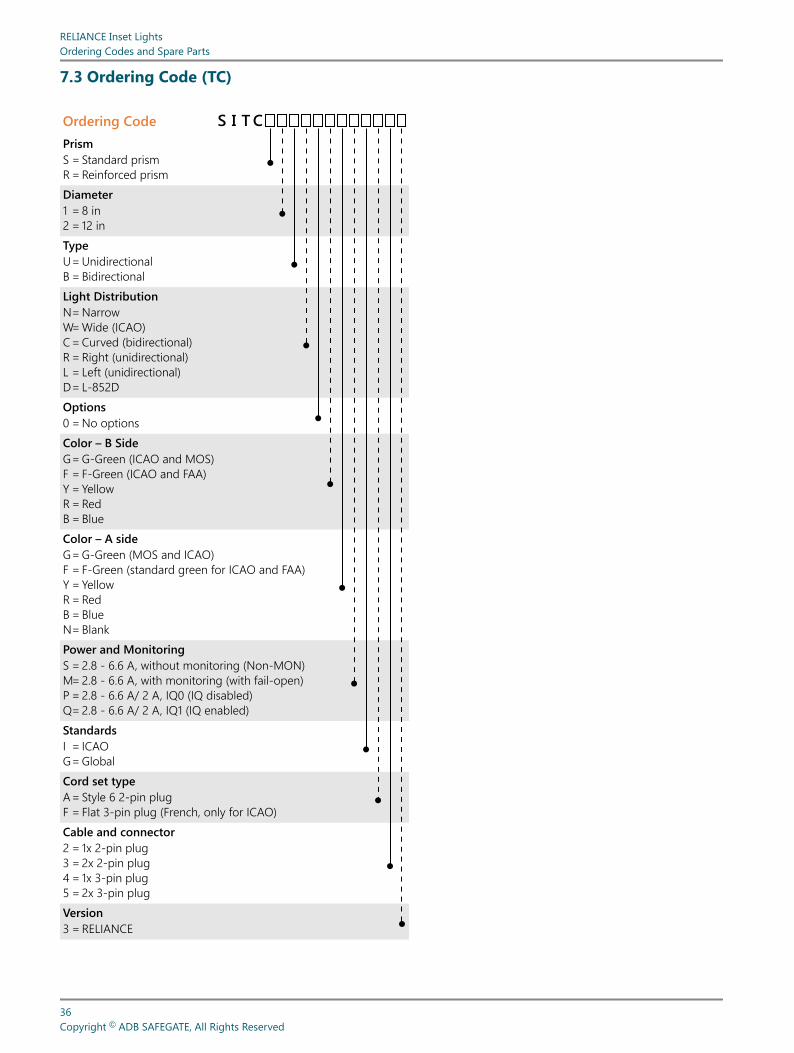
7.3 Ordering Code (TC)
Ordering Code CTISPrismS = Standard prismR = Reinforced prismDiameter1 = 8 in2 = 12 inTypeU = UnidirectionalB = BidirectionalLight DistributionN = NarrowW = Wide (ICAO)C = Curved (bidirectional)R = Right (unidirectional)L = Left (unidirectional)D = L-852DOptions0 = No optionsColor – B SideG = G-Green (ICAO and MOS)F = F-Green (ICAO and FAA)Y = YellowR = RedB = BlueColor – A sideG = G-Green (MOS and ICAO)F = F-Green (standard green for ICAO and FAA)Y = YellowR = RedB = BlueN = BlankPower and MonitoringS = 2.8 - 6.6 A, without monitoring (Non-MON)M = 2.8 - 6.6 A, with monitoring (with fail-open)P = 2.8 - 6.6 A/ 2 A, IQ0 (IQ disabled)Q = 2.8 - 6.6 A/ 2 A, IQ1 (IQ enabled)StandardsI = ICAOG = GlobalCord set typeA = Style 6 2-pin plugF = Flat 3-pin plug (French, only for ICAO)Cable and connector2 = 1x 2-pin plug3 = 2x 2-pin plug4 = 1x 3-pin plug5 = 2x 3-pin plugVersion3 = RELIANCE
RELIANCE Inset LightsOrdering Codes and Spare Parts
36Copyright © ADB SAFEGATE, All Rights Reserved
Note• Fixture is compatible with both shallow 8" and 12" and deep 12" bases, check base compatibility matrix.
• The IQ - functionality allows control and monitoring of the RELIANCE IQ. IQ1 fittings are pre - configured for thespecific position at delivery. This function is disabled in IQ0 fixtures but could be enabled later.
• IQ light fixtures are only available with connector option 2.
• Red is only available in 8 inch.
• Blue is only available in 8 inch.
• For global standard, the following color codes are used -
• Narrow color combinations : FF, FY, YF, YY, FN and YN
• Curved (C,R,L,D) color combinations : FF, YY, FN, and YN
• A 3-pin cable and connector are only available for the ICAO standard regardless of the color combination.
UM-0211, Rev. 4.0, 2022/02/08 37Copyright © ADB SAFEGATE, All Rights Reserved

7.4 Spare Parts (TC)
NoteContact ADB SAFEGATE for assistance with ordering spare parts, www.adbsafegate.com.
Description Quantity perOrder code
fitting order
1a Top plate bidirectional straight 1 1 SGE.SP17107
1b Top plate unidirectional straight 1 1 SGE.SP17108
2aPrism incl. prism gasket,protection plate and prismholder
1 2 SGE.SP17114
2bReinforced prism incl. prismgasket, protection plate andprism holder
1 2 SGE.SP17115
3 LED assembly incl. reflector, LED holder and cable
3a Curved Left Blue 1 1 SGE.SP19156
3b Curved Left F-Green L-852K(L) 1 1 SGE.SP19153
3c Curved Left G-Green 1 1 SGE.SP19152
3d Curved Left Red 1 1 SGE.SP19155
3e Curved Left Yellow L-852K(L) 1 1 SGE.SP19154
3f Curved Right Blue 1 1 SGE.SP19161
3g Curved Right F-Green L-852K(L) 1 1 SGE.SP19158
3h Curved Right G-Green 1 1 SGE.SP19157
3i Curved Right Red 1 1 SGE.SP19160
3j Curved Right Yellow L-852K(L) 1 1 SGE.SP19159
3k Narrow F-Green L-852C(L) 1 1 SGE.SP18929
3l Narrow G-Green 1 1 SGE.SP18928
3m Narrow Yellow L-852C(L) 1 1 SGE.SP18927
3n Wide Blue 1 1 SGE.SP19151
3o Wide F-Green 1 1 SGE.SP19148
3p Wide G-Green 1 1 SGE.SP19147
3q Wide Red 1 1 SGE.SP19150
3r Wide Yellow 1 1 SGE.SP19149
3s L-852D(L) Yellow 1 1 SGE.SP18952
3t L-852D(L) F-Green 1 1 SGE.SP18953
3u L-852D(L) Red 1 1 SGE.SP19162
4 LED Cable 180 mm 1 10 SGE.SP18650
5 Bottom cover gasket 1 10 SGE.SP17116
6aBottom cover assembly incl.RELIANCE IQ converter andsecondary cable
1 1 SGE.SP17117
6bBottom cover assembly incl. 1connector RELIANCE converterFAIL-OPEN and secondary cable
1 1 SGE.SP18059
RELIANCE Inset LightsOrdering Codes and Spare Parts
38Copyright © ADB SAFEGATE, All Rights Reserved

Description Quantity perOrder code
fitting order
6cBottom cover assembly incl. 2connector RELIANCE converterFAIL-OPEN and secondary cable
1 1 SGE.SP19316
6d Bottom cover assembly incl. 1connector RELIANCE converterNON-MON and secondarycable
1 1 SP.013101
6e Bottom cover assembly incl. 2connector RELIANCE converterNON-MON and secondarycable
1 1 SP.013102
7 Fuse resistor (only for lights withmonitoring option), pack of 20
1-2 20 6132.00.250
NoteAll screws for fastening are included.
NoteComponent availability or design may be subject to change due to unforeseen circumstances. This document issubject to change or new information from ADB SAFEGATE, as and when available or if required, with reservation forerror or price changes.For more information contact ADB SAFEGATE, see www.adbsafegate.com.
UM-0211, Rev. 4.0, 2022/02/08 39Copyright © ADB SAFEGATE, All Rights Reserved

7.5 Ordering Code (SB)
Ordering Code ICAO BSISPrismS = Standard prismR = Reinforced prismDiameter1 = 8 in2 = 12 inTypeU = UnidirectionalB = BidirectionalLight DistributionW = WideR = Right (unidirectional)L = Left (unidirectional)Options0 = No optionsColor – B SideR = RedColor – A sideR = RedN = BlankPower and MonitoringS = 2.8 - 6.6 A, without monitoring (Non-MON)M = 2.8 - 6.6 A, with monitoring (with fail-open)P = 2.8 - 6.6 A/ 2 A, IQ0 (IQ disabled)Q = 2.8 - 6.6 A/ 2 A, IQ1 (IQ enabled)StandardsI = ICAOCord set typeA = FAA Style 6 (2-pin) plugF = Flat 3-pin plugCable and connector2 = 1x 2-pin plug3 = 2x 2-pin plug4 = 1x 3-pin plug5 = 2x 3-pin plugVersion3 = RELIANCE
RELIANCE Inset LightsOrdering Codes and Spare Parts
40Copyright © ADB SAFEGATE, All Rights Reserved

Ordering Code FAA BSISPrismS = Standard prismR = Reinforced prismDiameter1 = 8 in2 = 12 inTypeU = UnidirectionalLight DistributionS = StraightOptions0 = No optionsColor – B SideR = RedColor – A sideN = BlankPower and MonitoringS = 2.8 - 6.6 A, without monitoring (Non-MON)M = 2.8 - 6.6 A, with monitoring (with fail-open)P = 2.8 - 6.6 A/ 2 A, IQ0 (IQ disabled)Q = 2.8 - 6.6 A/ 2 A, IQ1 (IQ enabled)StandardsF = FAA AC 150/5345-46ECord set typeA = Style 6 (2-pin) plugCable and connector2 = 1x 2-pin plugVersion3 = RELIANCE
UM-0211, Rev. 4.0, 2022/02/08 41Copyright © ADB SAFEGATE, All Rights Reserved
Note• Fixture compatible with both shallow 8 - inch and 12 - inch and deep 12 - inch bases, check base compatibility
matrix.
• The IQ - functionality allows control and monitoring of the RELIANCE IQ. IQ1 fittings are pre - configured for thespecific position at delivery. This function is disabled in IQ0 fixtures but could be enabled later.
• IQ light fixtures are only available with connector option 2.
• A 3-pin cable and connector are only available for the ICAO standard regardless of the color combination.
RELIANCE Inset LightsOrdering Codes and Spare Parts
42Copyright © ADB SAFEGATE, All Rights Reserved

7.6 Spare Parts (ICAO SB)
NoteContact ADB SAFEGATE for assistance with ordering spare parts, www.adbsafegate.com.
Description Quantity perOrder code
fitting order
1a Top plate bidirectional straight 1 1 SGE.SP17107
1b Top plate unidirectional straight 1 1 SGE.SP17108
2aPrism incl. prism gasket,protection plate and prismholder
1 2 SGE.SP17114
2bReinforced prism incl. prismgasket, protection plate andprism holder
1 2 SGE.SP17115
3 LED assembly incl. reflector, LED holder and cable
3a Curved Left Red 1 1 SGE.SP19155
3b Curved Right Red 1 1 SGE.SP19160
3c Wide Red 1 1 SGE.SP19150
4 LED Cable 180 mm 1 10 SGE.SP18650
5 Bottom cover gasket 1 10 SGE.SP17116
6aBottom cover assembly incl.RELIANCE IQ converter andsecondary cable
1 1 SGE.SP17117
6bBottom cover assembly incl. 1connector RELIANCE converterFAIL-OPEN and secondary cable
1 1 SGE.SP18059
6cBottom cover assembly incl. 2connector RELIANCE converterFAIL-OPEN and secondary cable
1 1 SGE.SP19316
6d Bottom cover assembly incl. 1connector RELIANCE converterNON-MON and secondarycable
1 1 SP.013101
6e Bottom cover assembly incl. 2connector RELIANCE converterNON-MON and secondarycable
1 1 SP.013102
7 Fuse resistor (only for lights withmonitoring option), pack of 20
1-2 20 6132.00.250
UM-0211, Rev. 4.0, 2022/02/08 43Copyright © ADB SAFEGATE, All Rights Reserved
NoteAll screws for fastening are included.
NoteComponent availability or design may be subject to change due to unforeseen circumstances. This document issubject to change or new information from ADB SAFEGATE, as and when available or if required, with reservation forerror or price changes.For more information contact ADB SAFEGATE, see www.adbsafegate.com.
RELIANCE Inset LightsOrdering Codes and Spare Parts
44Copyright © ADB SAFEGATE, All Rights Reserved
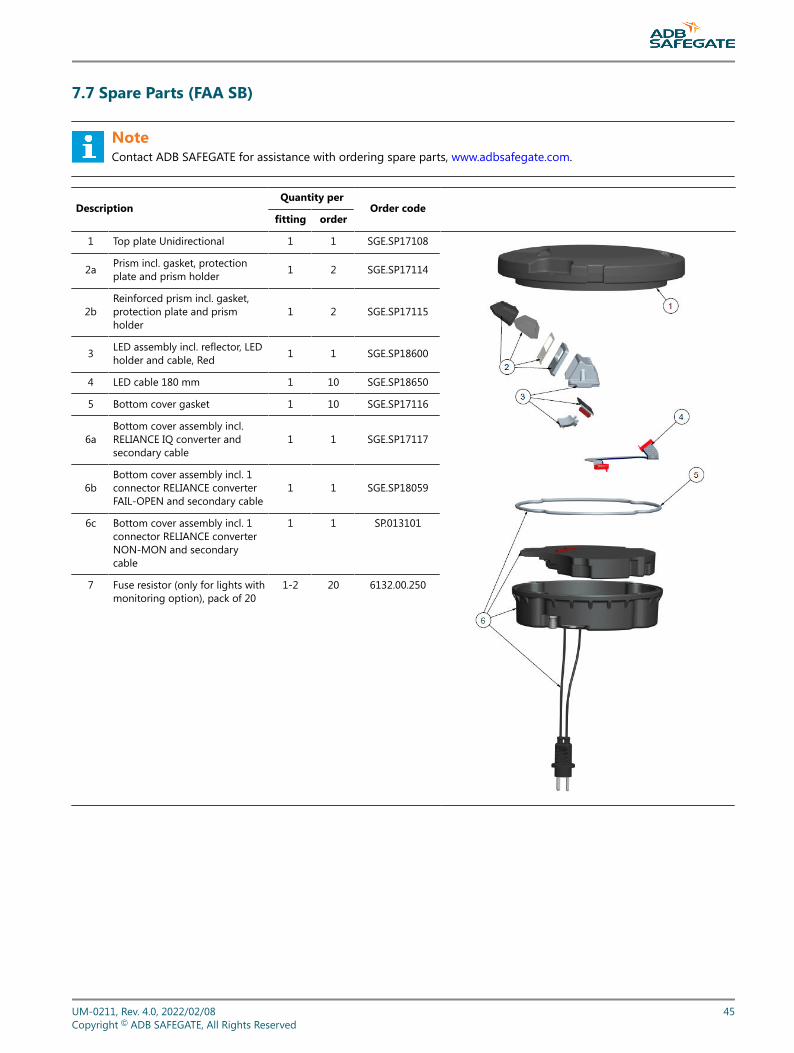
7.7 Spare Parts (FAA SB)
NoteContact ADB SAFEGATE for assistance with ordering spare parts, www.adbsafegate.com.
DescriptionQuantity per
Order codefitting order
1 Top plate Unidirectional 1 1 SGE.SP17108
2a Prism incl. gasket, protectionplate and prism holder 1 2 SGE.SP17114
2bReinforced prism incl. gasket,protection plate and prismholder
1 2 SGE.SP17115
3 LED assembly incl. reflector, LEDholder and cable, Red 1 1 SGE.SP18600
4 LED cable 180 mm 1 10 SGE.SP18650
5 Bottom cover gasket 1 10 SGE.SP17116
6aBottom cover assembly incl.RELIANCE IQ converter andsecondary cable
1 1 SGE.SP17117
6bBottom cover assembly incl. 1connector RELIANCE converterFAIL-OPEN and secondary cable
1 1 SGE.SP18059
6c Bottom cover assembly incl. 1connector RELIANCE converterNON-MON and secondarycable
1 1 SP.013101
7 Fuse resistor (only for lights withmonitoring option), pack of 20
1-2 20 6132.00.250
UM-0211, Rev. 4.0, 2022/02/08 45Copyright © ADB SAFEGATE, All Rights Reserved
NoteAll screws for fastening are included.Component availability or design may be subject to change due to unforeseen circumstances. This document issubject to change or new information from ADB SAFEGATE, as and when available or if required, with reservation forerror or price changes.For more information contact ADB SAFEGATE, see www.adbsafegate.com.
RELIANCE Inset LightsOrdering Codes and Spare Parts
46Copyright © ADB SAFEGATE, All Rights Reserved

Appendix A: INTEROPERABILITY
Top cover versions
NoteFor 8‑inch fixtures only.
Figure 29: Top cover versions
Manufactured after 2018-06Version 2 and 3
Manufactured before 2018-06
Base Installation - O-ring selection and retaining bolts
UM-0211, Rev. 4.0, 2022/02/08 47Copyright © ADB SAFEGATE, All Rights Reserved

Base installation – O-ring selection and retaining bolts
CAUTIONUse of incorrect combination of gaskets, bolts and nuts can create severe damages to the product installation andcreate multiple safety risks.To obtain a safe and watertight installation the O-ring and retaining bolt stated in the document must be used.You need to know what base the light fixture will be installed in, in order to choose the correct gasket, bolts and nuts.Failure to follow these cautions can result in equipment damage or aircraft FOD.
Table 3: Manufactured before 2018-06 version 1
Base type Required O-ring
Bolt installation Stud installation
Requireddimension
Recommendedtorque
Required nut Recommendedtorque
Base 8‑in-13X-.. SGE.SP13092 (black)10 pcs M10×25 40 Nm M10 40 Nm
Base MK2 8‑in SGE.SP13092 (black)10 pcs M10×25 40 Nm M10 40 Nm
IDM 6494 SGE.SP13092 (black)10 pcs M10×25 40 Nm M10 40 Nm
Table 4: Manufactured after 2018-06 version 2 and 3
Base type Required O-ring
Bolt installation Stud installation
Requireddimension
Recommendedtorque
Required nut Recommendedtorque
RELIANCE Base 8"-135 mm
Red O-RingSGE.SP24523/10pcSGE.SP24526/100pc
1411.20.522Metric screw kit
25 mm40 Nm + Loctite 638
1411.20.430Self-lockingnut kit H100
35 Nm + Loctite 638
ERNI 8-in EE08(150 mm)
Blue O-RingSGE.SP24521/10 pcSGE.SP24524/100 pc
1411.20.522Metric screw kit
25 mm40 Nm + Loctite 638
1411.20.430Self-lockingnut kit H100
35 Nm +Loctite 638
ERNI 8-in ED08(133 mm)
Blue O-RingSGE.SP24521/10 pcSGE.SP24524/100 pc
1411.20.522Metric screw kit
25 mm40 Nm + Loctite 638
1411.20.430Self-lockingnut kit H100
35 Nm + Loctite 638
Thorn 8-in 100 mm Red O-RingSGE.SP24523/10 pcSGE.SP24526/100 pc
1411.20.522Metric screw kit
25 mm40 Nm + Loctite 638
1411.20.430Self-lockingnut kit H100
35 Nm +Loctite 638
Thorn 8-in 133 mm Red O-RingSGE.SP24523/10 pcSGE.SP24526/100 pc
1411.20.522Metric screw kit
25 mm40 Nm + Loctite 638
1411.20.430Self-lockingnut kit H100
35 Nm + Loctite 638
Thorn 8-inMK2 133 mm
Red O-RingSGE.SP24523/10 pcSGE.SP24526/100 pc
1411.20.522Metric screw kit
25 mm40 Nm + Loctite 638
1411.20.430Self-lockingnut kit H100
35 Nm + Loctite 638
IDM 6494 (120 mm) Red O-RingSGE.SP24523/10 pcSGE.SP24526/100 pc
1411.20.522Metric screw kit
25 mm40 Nm + Loctite 638
1411.20.430Self-lockingnut kit H100
35 Nm + Loctite 638
ADB 8-in Eurobase Blue O-RingSGE.SP242521/10 pcSGE.SP24524/100 pc
1411.20.522Metric screw kit
25 mm
21 Nm +Loctite 2701 or 638
1411.20.430Self-lockingnut kit H100
No Loctite
RELIANCE Inset LightsINTEROPERABILITY
48Copyright © ADB SAFEGATE, All Rights Reserved

Table 4: Manufactured after 2018-06 version 2 and 3 (Continued)
Base type Required O-ring
Bolt installation Stud installation
Requireddimension
Recommendedtorque
Required nut Recommendedtorque
ADB 8-in HPI Grey O-RingSGE.SP24522/10 pcSGE.SP24525/100 pc
1411.20.522Metric screw kit
25 mm
21 Nm +Loctite 2701 or 638
1411.20.430Self-lockingnut kit H100
No Loctite
Adapter ring ADB8-in–12-in
Blue O-RingSGE.SP24521/10 pcSGE.SP24524/100 pc
1411.20.522Metric screw kit
25 mm
21 Nm +Loctite 2701 or 638
1411.20.430Self-lockingnut kit H100
No Loctite
Adapter ring SG/Thorn/ID8-in–12-in
Red O-RingSGE.SP24523/10 pcSGE.SP24526/100 pc
1411.20.522Metric screw kit
25 mm
40 Nm + Loctite 638 1411.20.430Self-lockingnut kit H100
35 Nm + Loctite 638
The pictures below show photos of the bases mentioned above and the frame show the color of the intended gasket.
Figure 30: Shallow bases
IDM 6494 Base 8”-13X-..
Base MK2 8” Base 8”-13X-..
HPI ERNI EE08 Eurobase
UM-0211, Rev. 4.0, 2022/02/08 49Copyright © ADB SAFEGATE, All Rights Reserved

RELIANCE Inset LightsINTEROPERABILITY
50Copyright © ADB SAFEGATE, All Rights Reserved
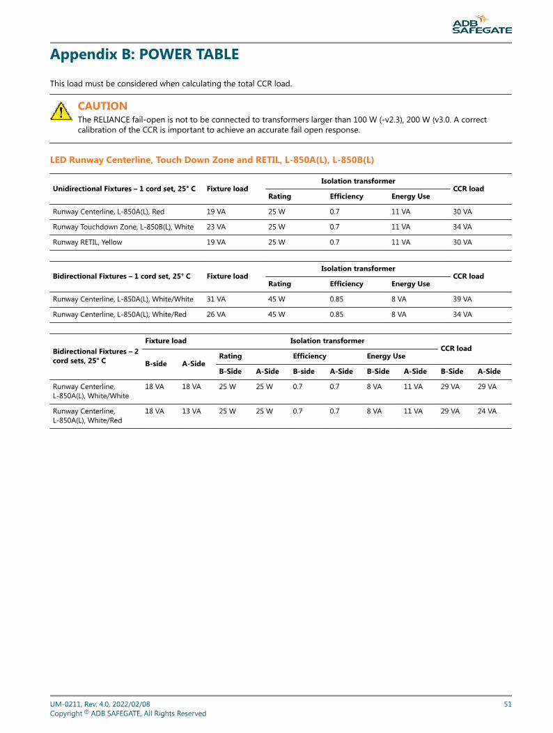
Appendix B: POWER TABLE
This load must be considered when calculating the total CCR load.
CAUTIONThe RELIANCE fail-open is not to be connected to transformers larger than 100 W (-v2.3), 200 W (v3.0. A correctcalibration of the CCR is important to achieve an accurate fail open response.
LED Runway Centerline, Touch Down Zone and RETIL, L-850A(L), L-850B(L)
Unidirectional Fixtures – 1 cord set, 25° C Fixture loadIsolation transformer
CCR loadRating Efficiency Energy Use
Runway Centerline, L-850A(L), Red 19 VA 25 W 0.7 11 VA 30 VA
Runway Touchdown Zone, L-850B(L), White 23 VA 25 W 0.7 11 VA 34 VA
Runway RETIL, Yellow 19 VA 25 W 0.7 11 VA 30 VA
Bidirectional Fixtures – 1 cord set, 25° C Fixture loadIsolation transformer
CCR loadRating Efficiency Energy Use
Runway Centerline, L-850A(L), White/White 31 VA 45 W 0.85 8 VA 39 VA
Runway Centerline, L-850A(L), White/Red 26 VA 45 W 0.85 8 VA 34 VA
Bidirectional Fixtures – 2cord sets, 25° C
Fixture load Isolation transformerCCR load
B-side A-SideRating Efficiency Energy Use
B-Side A-Side B-side A-Side B-Side A-Side B-Side A-Side
Runway Centerline,L-850A(L), White/White
18 VA 18 VA 25 W 25 W 0.7 0.7 8 VA 11 VA 29 VA 29 VA
Runway Centerline,L-850A(L), White/Red
18 VA 13 VA 25 W 25 W 0.7 0.7 8 VA 11 VA 29 VA 24 VA
UM-0211, Rev. 4.0, 2022/02/08 51Copyright © ADB SAFEGATE, All Rights Reserved
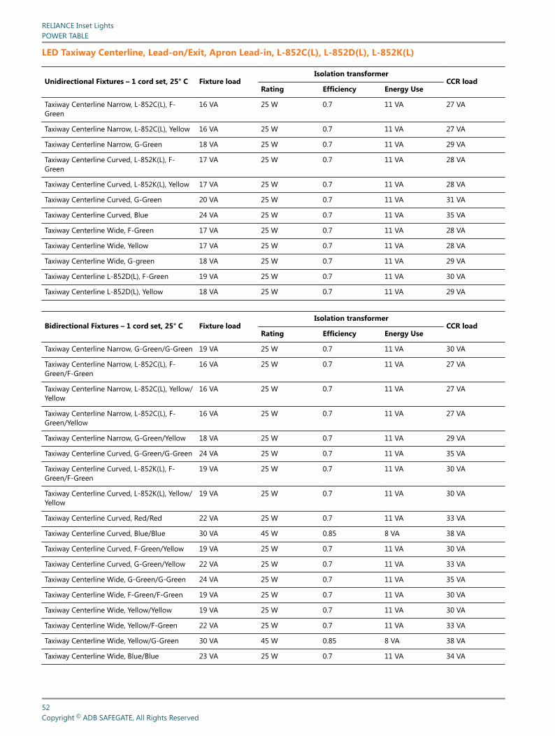
LED Taxiway Centerline, Lead-on/Exit, Apron Lead-in, L-852C(L), L-852D(L), L-852K(L)
Unidirectional Fixtures – 1 cord set, 25° C Fixture loadIsolation transformer
CCR loadRating Efficiency Energy Use
Taxiway Centerline Narrow, L-852C(L), F-Green
16 VA 25 W 0.7 11 VA 27 VA
Taxiway Centerline Narrow, L-852C(L), Yellow 16 VA 25 W 0.7 11 VA 27 VA
Taxiway Centerline Narrow, G-Green 18 VA 25 W 0.7 11 VA 29 VA
Taxiway Centerline Curved, L-852K(L), F-Green
17 VA 25 W 0.7 11 VA 28 VA
Taxiway Centerline Curved, L-852K(L), Yellow 17 VA 25 W 0.7 11 VA 28 VA
Taxiway Centerline Curved, G-Green 20 VA 25 W 0.7 11 VA 31 VA
Taxiway Centerline Curved, Blue 24 VA 25 W 0.7 11 VA 35 VA
Taxiway Centerline Wide, F-Green 17 VA 25 W 0.7 11 VA 28 VA
Taxiway Centerline Wide, Yellow 17 VA 25 W 0.7 11 VA 28 VA
Taxiway Centerline Wide, G-green 18 VA 25 W 0.7 11 VA 29 VA
Taxiway Centerline L-852D(L), F-Green 19 VA 25 W 0.7 11 VA 30 VA
Taxiway Centerline L-852D(L), Yellow 18 VA 25 W 0.7 11 VA 29 VA
Bidirectional Fixtures – 1 cord set, 25° C Fixture loadIsolation transformer
CCR loadRating Efficiency Energy Use
Taxiway Centerline Narrow, G-Green/G-Green 19 VA 25 W 0.7 11 VA 30 VA
Taxiway Centerline Narrow, L-852C(L), F-Green/F-Green
16 VA 25 W 0.7 11 VA 27 VA
Taxiway Centerline Narrow, L-852C(L), Yellow/Yellow
16 VA 25 W 0.7 11 VA 27 VA
Taxiway Centerline Narrow, L-852C(L), F-Green/Yellow
16 VA 25 W 0.7 11 VA 27 VA
Taxiway Centerline Narrow, G-Green/Yellow 18 VA 25 W 0.7 11 VA 29 VA
Taxiway Centerline Curved, G-Green/G-Green 24 VA 25 W 0.7 11 VA 35 VA
Taxiway Centerline Curved, L-852K(L), F-Green/F-Green
19 VA 25 W 0.7 11 VA 30 VA
Taxiway Centerline Curved, L-852K(L), Yellow/Yellow
19 VA 25 W 0.7 11 VA 30 VA
Taxiway Centerline Curved, Red/Red 22 VA 25 W 0.7 11 VA 33 VA
Taxiway Centerline Curved, Blue/Blue 30 VA 45 W 0.85 8 VA 38 VA
Taxiway Centerline Curved, F-Green/Yellow 19 VA 25 W 0.7 11 VA 30 VA
Taxiway Centerline Curved, G-Green/Yellow 22 VA 25 W 0.7 11 VA 33 VA
Taxiway Centerline Wide, G-Green/G-Green 24 VA 25 W 0.7 11 VA 35 VA
Taxiway Centerline Wide, F-Green/F-Green 19 VA 25 W 0.7 11 VA 30 VA
Taxiway Centerline Wide, Yellow/Yellow 19 VA 25 W 0.7 11 VA 30 VA
Taxiway Centerline Wide, Yellow/F-Green 22 VA 25 W 0.7 11 VA 33 VA
Taxiway Centerline Wide, Yellow/G-Green 30 VA 45 W 0.85 8 VA 38 VA
Taxiway Centerline Wide, Blue/Blue 23 VA 25 W 0.7 11 VA 34 VA
RELIANCE Inset LightsPOWER TABLE
52Copyright © ADB SAFEGATE, All Rights Reserved

Bidirectional Fixtures – 1 cord set, 25° C Fixture loadIsolation transformer
CCR loadRating Efficiency Energy Use
Taxiway Centerline L-852D(L), F-Green/F-Green
21 VA 25 W 0.7 11 VA 32 VA
Taxiway Centerline L-852D(L), Yellow/Yellow 22 VA 25 W 0.7 11 VA 33 VA
Taxiway Centerline L-852D(L), Yellow/F-Green 22 VA 25 W 0.7 11 VA 33 VA
Taxiway Centerline extra wide, Red/Yellow 22 VA 25 W 0.7 11 VA 33 VA
Taxiway Centerline L-852D(L), Red/Red 24 VA 25 W 0.7 11 VA 35 VA
Bidirectional Fixtures – 2cord sets, 25° C
Fixture load Isolation transformerCCR load
B-side A-SideRating Efficiency Energy Use
B-Side A-Side B-side A-Side B-Side A-Side B-Side A-Side
Taxiway Centerline Narrow,G-Green/G-Green
12 VA 12 VA 25 W 25 W 0.7 0.7 11 VA 11 VA 23 VA 23 VA
Taxiway CenterlineNarrow, L-852C(L), F-Green/F-Green
10 VA 10 VA 25 W 25 W 0.7 0.7 11 VA 11 VA 21 VA 21 VA
Taxiway Centerline Narrow,L-852C(L), Yellow/Yellow
10 VA 10 VA 25 W 25 W 0.7 0.7 11 VA 11 VA 21 VA 21 VA
Taxiway Centerline Narrow,L-852C(L), F-Green/Yellow
10 VA 10 VA 25 W 25 W 0.7 0.7 11 VA 11 VA 21 VA 21 VA
Taxiway Centerline Narrow,G-Green/Yellow
12 VA 10 VA 25 W 25 W 0.7 0.7 11 VA 11 VA 23 VA 21 VA
Taxiway Centerline Curved,G-Green/G-Green
14 VA 14 VA 25 W 25 W 0.7 0.7 11 VA 11 VA 25 VA 25 VA
Taxiway CenterlineCurved, L-852K(L), F-Green/F-Green
11 VA 11 VA 25 W 25 W 0.7 0.7 11 VA 11 VA 22 VA 22 VA
Taxiway Centerline Curved,L-852K(L), Yellow/Yellow
11 VA 11 VA 25 W 25 W 0.7 0.7 11 VA 11 VA 22 VA 22 VA
Taxiway Centerline Curved,Red/Red
13 VA 13 VA 25 W 25 W 0.7 0.7 11 VA 11 VA 24 VA 24 VA
Taxiway Centerline Curved,Blue/Blue
18 VA 18 VA 25 W 25 W 0.7 0.7 11 VA 11 VA 29 VA 29 VA
Taxiway Centerline Curved,F-Green/Yellow
11 VA 11 VA 25 W 25 W 0.7 0.7 11 VA 11 VA 22 VA 22 VA
Taxiway Centerline Curved,G-Green/Yellow
14 VA 11 VA 25 W 25 W 0.7 0.7 11 VA 11 VA 25 VA 22 VA
Taxiway Centerline Wide,G-Green/G-Green
14 VA 14 VA 25 W 25 W 0.7 0.7 11 VA 11 VA 25 VA 25 VA
Taxiway Centerline Wide,F-Green/F-Green
11 VA 11 VA 25 W 25 W 0.7 0.7 11 VA 11 VA 25 VA 25 VA
Taxiway Centerline Wide,Yellow/Yellow
11 VA 11 VA 25 W 25 W 0.7 0.7 11 VA 11 VA 22 VA 22 VA
Taxiway Centerline Wide,Yellow/F-Green
11 VA 11 VA 25 W 25 W 0.7 0.7 11 VA 11 VA 22 VA 22 VA
Taxiway Centerline Wide,Yellow/G-Green
14 VA 11 VA 25 W 25 W 0.7 0.7 11 VA 11 VA 22 VA 22 VA
UM-0211, Rev. 4.0, 2022/02/08 53Copyright © ADB SAFEGATE, All Rights Reserved

Bidirectional Fixtures – 2cord sets, 25° C
Fixture load Isolation transformerCCR load
B-side A-SideRating Efficiency Energy Use
B-Side A-Side B-side A-Side B-Side A-Side B-Side A-Side
Taxiway Centerline Wide,Blue/Blue
18 VA 18 VA 25 W 25 W 0.7 0.7 11 VA 11 VA 29 VA 29 VA
Taxiway CenterlineL-852D(L), F-Green/F-Green
13 VA 13 VA 25 W 25 W 0.7 0.7 11 VA 11 VA 24 VA 24 VA
Taxiway CenterlineL-852D(L), Yellow/Yellow
12 VA 12 VA 25 W 25 W 0.7 0.7 11 VA 11 VA 23 VA 23 VA
Taxiway CenterlineL-852D(L), Yellow/F-Green
13 VA 12 VA 25 W 25 W 0.7 0.7 11 VA 11 VA 24 VA 23 VA
Taxiway Centerline extrawide, Red/Yellow
14 VA 12 VA 25 W 25 W 0.7 0.7 11 VA 11 VA 25 VA 23 VA
Taxiway CenterlineL-852D(L), Red/Red
14 VA 14 VA 25 W 25 W 0.7 0.7 11 VA 11 VA 25 VA 25 VA
LED Stopbar
Unidirectional Fixtures – 1 cord set, 25° C Fixture loadIsolation transformer
CCR loadRating Efficiency Energy Use
Stopbar, Red 19 VA 25 W 0.7 11 VA 30 VA
Stopbar, L-852S(L), Red 23 VA 25 W 0.7 11 VA 34 VA
Bidirectional Fixtures – 1 cord set, 25° C Fixture loadIsolation transformer
CCR loadRating Efficiency Energy Use
Stopbar, Red/Red 24 VA 25 W 0.7 11 VA 35 VA
Bidirectional Fixtures – 2cord sets, 25° C
Fixture load Isolation transformerCCR load
B-side A-SideRating Efficiency Energy Use
B-Side A-Side B-side A-Side B-Side A-Side B-Side A-Side
Stopbar, Red/Red 14 VA 14 VA 25 W 25 W 0.7 0.7 11 VA 11 VA 25 VA 25 VA
RELIANCE Inset LightsPOWER TABLE
54Copyright © ADB SAFEGATE, All Rights Reserved
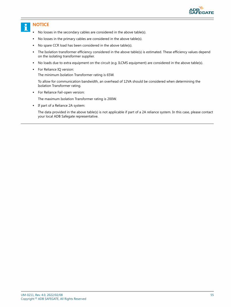
NOTICE• No losses in the secondary cables are considered in the above table(s).
• No losses in the primary cables are considered in the above table(s).
• No spare CCR load has been considered in the above table(s).
• The Isolation transformer efficiency considered in the above table(s) is estimated. These efficiency values dependon the isolating transformer supplier.
• No loads due to extra equipment on the circuit (e.g. ILCMS equipment) are considered in the above table(s).
• For Reliance IQ version:The minimum Isolation Transformer rating is 65W.
To allow for communication bandwidth, an overhead of 12VA should be considered when determining theIsolation Transformer rating.
• For Reliance Fail-open version:
The maximum Isolation Transformer rating is 200W.
• If part of a Reliance 2A system:
The data provided in the above table(s) is not applicable if part of a 2A reliance system. In this case, please contactyour local ADB Safegate representative.
UM-0211, Rev. 4.0, 2022/02/08 55Copyright © ADB SAFEGATE, All Rights Reserved

RELIANCE Inset LightsPOWER TABLE
56Copyright © ADB SAFEGATE, All Rights Reserved
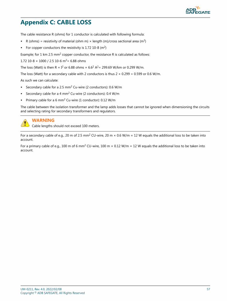
Appendix C: CABLE LOSS
The cable resistance R (ohms) for 1 conductor is calculated with following formula:
• R (ohms) = resistivity of material (ohm m) × length (m)/cross sectional area (m2)
• For copper conductors the resistivity is 1.72 10-8 (m2)
Example; for 1 km 2.5 mm2 copper conductor, the resistance R is calculated as follows:
1.72 10-8 × 1000 / 2.5 10-6 m2= 6.88 ohms
The loss (Watt) is then R × I2 or 6.88 ohms × 6.62 A2= 299.69 W/km or 0.299 W/m.
The loss (Watt) for a secondary cable with 2 conductors is thus 2 × 0.299 = 0.599 or 0.6 W/m.
As such we can calculate:
• Secondary cable for a 2.5 mm2 Cu-wire (2 conductors): 0.6 W/m
• Secondary cable for a 4 mm2 Cu-wire (2 conductors): 0.4 W/m
• Primary cable for a 6 mm2 Cu-wire (1 conductor): 0.12 W/m
The cable between the isolation transformer and the lamp adds losses that cannot be ignored when dimensioning the circuitsand selecting rating for secondary transformers and regulators.
WARNINGCable lengths should not exceed 100 meters.
For a secondary cable of e.g., 20 m of 2.5 mm2 CU-wire, 20 m × 0.6 W/m = 12 W equals the additional loss to be taken intoaccount.
For a primary cable of e.g., 100 m of 6 mm2 CU-wire, 100 m × 0.12 W/m = 12 W equals the additional loss to be taken intoaccount.
UM-0211, Rev. 4.0, 2022/02/08 57Copyright © ADB SAFEGATE, All Rights Reserved

RELIANCE Inset LightsCABLE LOSS
58Copyright © ADB SAFEGATE, All Rights Reserved
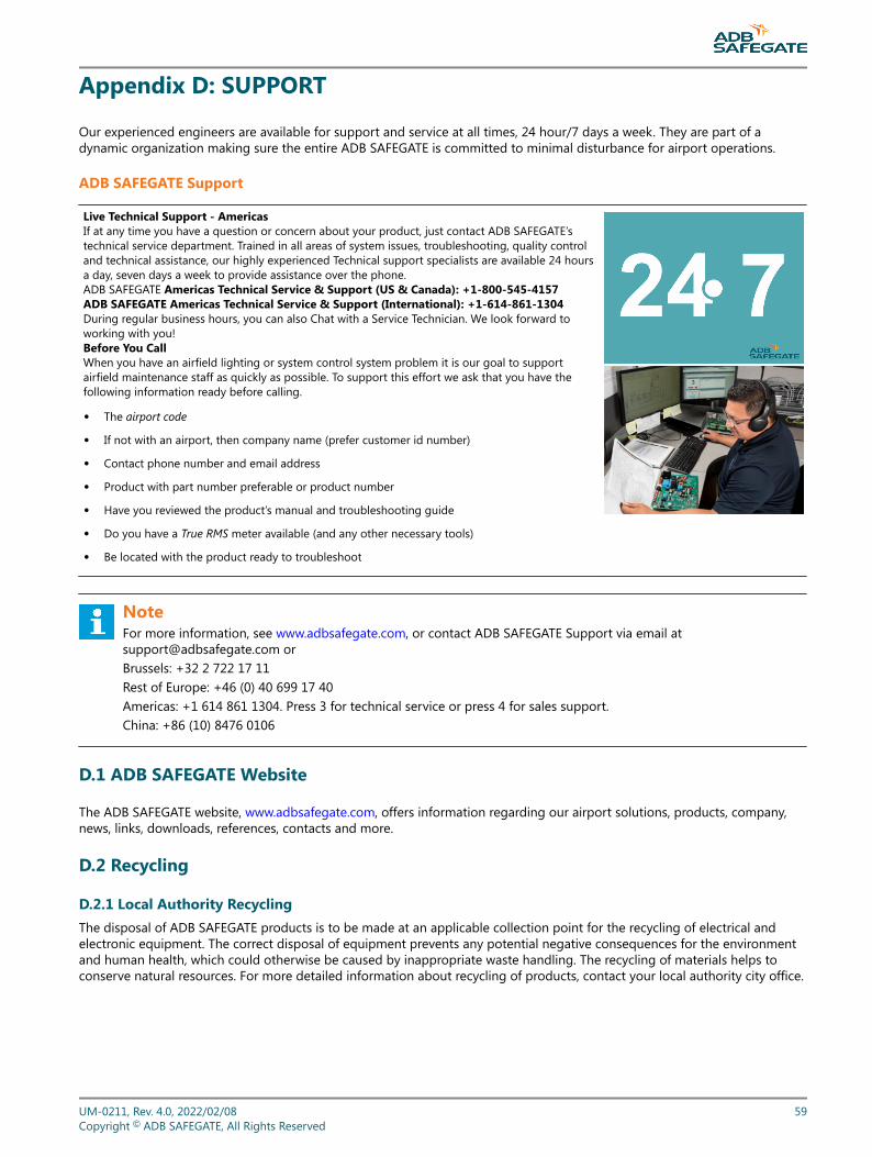
Appendix D: SUPPORT
Our experienced engineers are available for support and service at all times, 24 hour/7 days a week. They are part of adynamic organization making sure the entire ADB SAFEGATE is committed to minimal disturbance for airport operations.
ADB SAFEGATE Support
Live Technical Support - AmericasIf at any time you have a question or concern about your product, just contact ADB SAFEGATE’stechnical service department. Trained in all areas of system issues, troubleshooting, quality controland technical assistance, our highly experienced Technical support specialists are available 24 hoursa day, seven days a week to provide assistance over the phone.ADB SAFEGATE Americas Technical Service & Support (US & Canada): +1-800-545-4157ADB SAFEGATE Americas Technical Service & Support (International): +1-614-861-1304During regular business hours, you can also Chat with a Service Technician. We look forward toworking with you!Before You CallWhen you have an airfield lighting or system control system problem it is our goal to supportairfield maintenance staff as quickly as possible. To support this effort we ask that you have thefollowing information ready before calling.
• The airport code
• If not with an airport, then company name (prefer customer id number)
• Contact phone number and email address
• Product with part number preferable or product number
• Have you reviewed the product’s manual and troubleshooting guide
• Do you have a True RMS meter available (and any other necessary tools)
• Be located with the product ready to troubleshoot
NoteFor more information, see www.adbsafegate.com, or contact ADB SAFEGATE Support via email [email protected] orBrussels: +32 2 722 17 11Rest of Europe: +46 (0) 40 699 17 40Americas: +1 614 861 1304. Press 3 for technical service or press 4 for sales support.China: +86 (10) 8476 0106
D.1 ADB SAFEGATE Website
The ADB SAFEGATE website, www.adbsafegate.com, offers information regarding our airport solutions, products, company,news, links, downloads, references, contacts and more.
D.2 Recycling
D.2.1 Local Authority RecyclingThe disposal of ADB SAFEGATE products is to be made at an applicable collection point for the recycling of electrical andelectronic equipment. The correct disposal of equipment prevents any potential negative consequences for the environmentand human health, which could otherwise be caused by inappropriate waste handling. The recycling of materials helps toconserve natural resources. For more detailed information about recycling of products, contact your local authority city office.
UM-0211, Rev. 4.0, 2022/02/08 59Copyright © ADB SAFEGATE, All Rights Reserved

D.2.2 ADB SAFEGATE RecyclingADB SAFEGATE is fully committed to environmentally-conscious manufacturing with strict monitoring of our own processes aswell as supplier components and sub-contractor operations. ADB SAFEGATE offers a recycling program for our products to allcustomers worldwide, whether or not the products were sold within the EU.
ADB SAFEGATE products and/or specific electrical and electronic component parts which are fully removed/separated fromany customer equipment and returned will be accepted for our recycling program.
All items returned must be clearly labeled as follows:
• For ROHS/WEEE Recycling
• Sender contact information (Name, Business Address, Phone number).
• Main Unit Serial Number.
ADB SAFEGATE will continue to monitor and update according for any future requirements for EU directives as and when EUmember states implement new regulations and or amendments. It is our aim to maintain our compliance plan and assist ourcustomers.
RELIANCE Inset LightsSUPPORT
60Copyright © ADB SAFEGATE, All Rights Reserved
Company Addresses
ADB SAFEGATE ADB SAFEGATE, Belgium:Leuvensesteenweg 585,B-1930 ZaventemBelgium
Contact:Tel.: +32 2 722 17 11,Fax: +32 2 722 17 64
Email: [email protected]: www.adbsafegate.com
Americas LLC ADB SAFEGATE, Americas:977 Gahanna Parkway,Columbus, OH 43230USA
Contact:Tel.: +1 (614) 861 1304,Fax: +1 (614) 864 2069
Email: [email protected]: www.adbsafegate.com
ADB SAFEGATE Sweden AB ADB SAFEGATE, Sweden:Djurhagegatan 19SE-213 76 MalmöSweden
Contact:Tel.: +46 (0)40 699 17 00,Fax: +46 (0)40 699 17 30
Email: [email protected]: www.adbsafegate.com
ADB SAFEGATE Airfield Technologies Ltd. China ADB SAFEGATE, China:Unit 603, D Block,CAMIC International Convention Center,No 3, Hua Jia Di East road, ChaoYang district,Beijing 100102P.R. China
Contact:Tel.: +86 (10) 8476 0106,Fax: +86 (10) 8476 0090
Email: [email protected]: www.adbsafegate.com
ADB SAFEGATE Germany GmbH ADB SAFEGATE Germany GmbH, Mannheim:Konrad-Zuse-Ring 6,D-68163 MannheimGermany
Contact:Tel.: +49 (621) 87 55 76-0,Fax: +49 (621) 87 55 76-55
Email: [email protected]: www.adbsafegate.com
UM-0211, Rev. 4.0, 2022/02/08 61Copyright © ADB SAFEGATE, All Rights Reserved
Related Documents