Aircraft Engineering Reliability and Maintenance Management 2013 12002640 Page 1 Reliability and Maintenance Management: Landing Gear of Saab 340b: Rishab Anand (12002640) Department of Aircraft Engineering, Perth College, University of Highland and Island

Welcome message from author
This document is posted to help you gain knowledge. Please leave a comment to let me know what you think about it! Share it to your friends and learn new things together.
Transcript
Aircraft Engineering Reliability and Maintenance Management 2013
12002640 Page 1
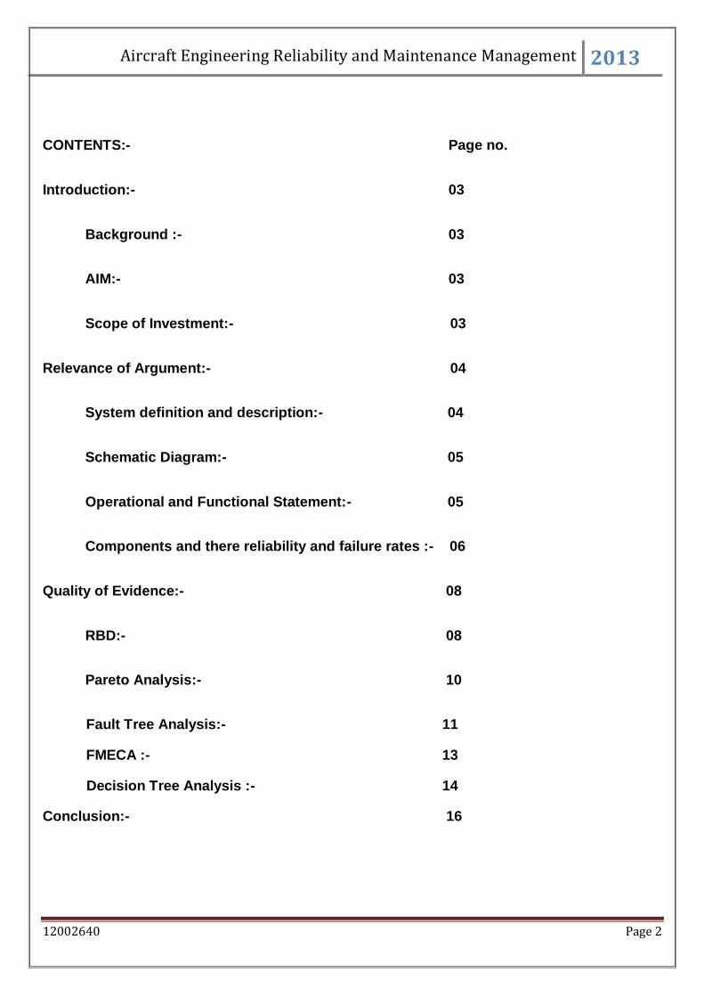
Reliability and Maintenance Management:
Landing Gear of Saab 340b:
Rishab Anand (12002640)
Department of Aircraft Engineering,
Perth College,
University of Highland and Island
Aircraft Engineering Reliability and Maintenance Management 2013
12002640 Page 2
CONTENTS:- Page no.
Introduction:- 03
Background :- 03
AIM:- 03
Scope of Investment:- 03
Relevance of Argument:- 04
System definition and description:- 04
Schematic Diagram:- 05
Operational and Functional Statement:- 05
Components and there reliability and failure rates :- 06
Quality of Evidence:- 08
RBD:- 08
Pareto Analysis:- 10
Fault Tree Analysis:- 11
FMECA :- 13
Decision Tree Analysis :- 14
Conclusion:- 16
Aircraft Engineering Reliability and Maintenance Management 2013
12002640 Page 3
Introduction:-
Background :-
Landing gear is the most important structure of an aircraft, as it is solely responsible for the
aircraft to do all the ground operations from taxing to take- off and landing, but it was found
that landing gear creates a massive drag when the aircraft is in air. So, in order to reduce
the drag and increase the efficiency of aircraft, landing gear is retracted when the aircraft is
in air and extended just before reaching ground. Now coming on to the other subject of this
report, Saab 340B is a twin turboprop engine aircraft, with a tricycle landing gear
configuration.
Aim :-
The main aim of this report is to see how reliable the landing gear extension and retraction
system is, for the Aircraft Saab 340B.
Scope of Investment:-
The Scope will be in the operation of extension and retraction of landing gear. MSG 3
analysis can be done on this to know about the different ways of feasible maintenance. It
will further provide ways to reduce the risk factors and failure rates. Analysis like FMECA,
Decision tree, and others gives us easy ways to fight with the risks associated with the
system.
RCM:-
RCM or Reliability Centred Maintenance is a basic process which ensures that the Landing
Gear extension and retraction is operating as perfectly as it is assigned to, and provide
answers to a few basic questions like “What is the item supposed to do and its associated
Aircraft Engineering Reliability and Maintenance Management 2013
12002640 Page 4
performance standards? In what ways can it fail to provide the required functions? What are
the events that cause each failure? What happens when each failure occurs? In what way
does each failure matter? What systematic task can be performed proactively to prevent, or
to diminish to a satisfactory degree, the consequences of the failure? What must be done if
a suitable preventive task cannot be found?” (Handle Consulting and Training, 2013)
Relevance of argument:-
System definition and description:-
Saab 340B has a conventional tricycle landing gear, with each gear having duel wheels. Its
nose gear is located in the fuselage and the main gear is located in the engine nacelles.
Retraction and extensions are basic necessities of an Aircraft. When the aircraft is airborne,
the landing gear has no basic role to play. So, it was found that the landing gear was
creating an awful amount of drag. In the crisis of sustainable energy, and the demand of the
market for making money, the extension and retraction system was initiated in aircrafts. It
was also found out that if the drag can be reduced, fuel burn will get reduced. It will get
reduced because of more thrust generation. More thrust will generate more Lift and more
velocity, and this is achieved by the same amount of engine power that was used before .
This will reduce the fuel usage, and will also reduce the time required for journey. And thus
it can boost the aviation sector by bringing cheap and environmental friendly aviation, and
can make lots of money as well for the airlines. It was after that the used of Landing gear
extension and retraction being implemented in the industry in all the aircrafts. In SAAB 340
B, all of the landing gears of the aircraft retract in forward direction. The gears can be
extended and retracted in normal mode, and can also be extended in emergency mode.
Aircraft Engineering Reliability and Maintenance Management 2013
12002640 Page 5
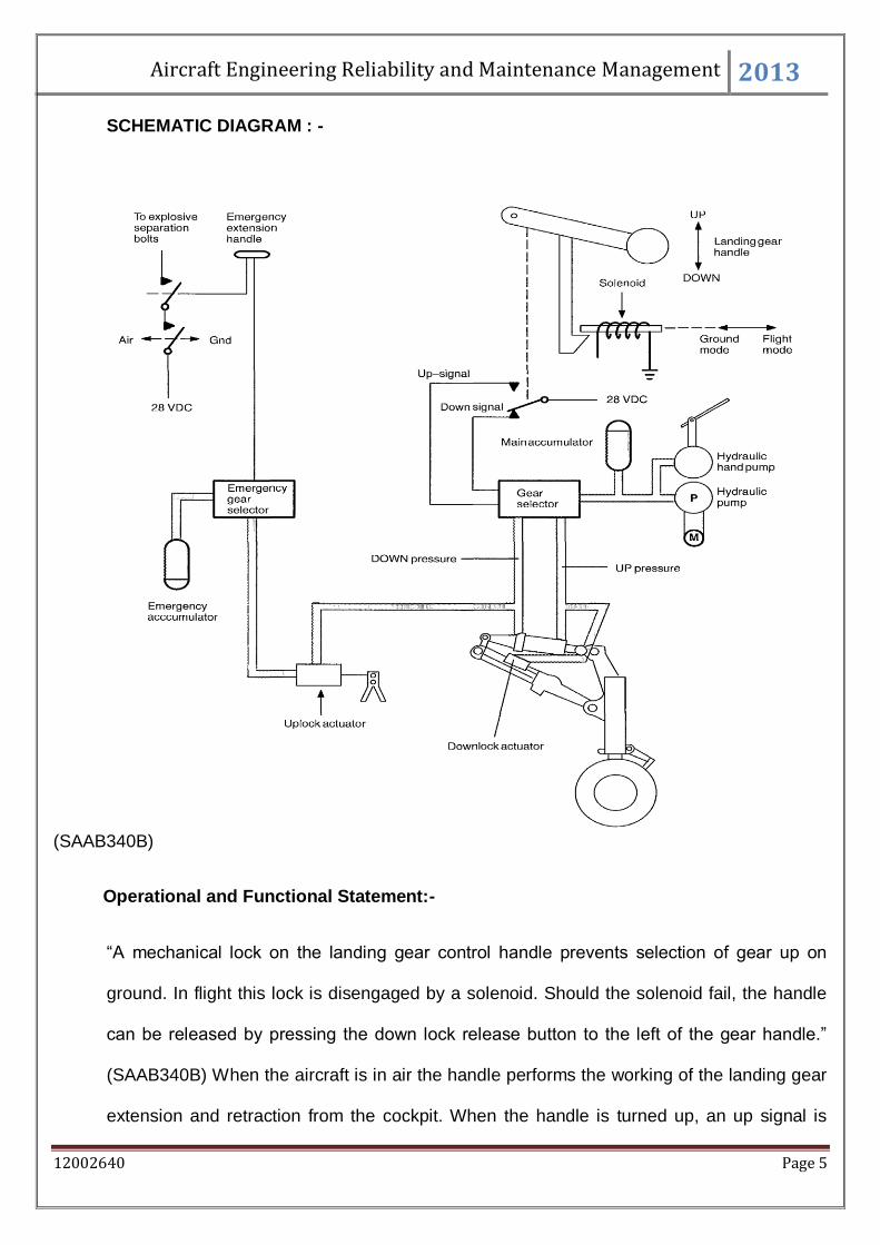
SCHEMATIC DIAGRAM : -
(SAAB340B)
Operational and Functional Statement:-
“A mechanical lock on the landing gear control handle prevents selection of gear up on
ground. In flight this lock is disengaged by a solenoid. Should the solenoid fail, the handle
can be released by pressing the down lock release button to the left of the gear handle.”
(SAAB340B) When the aircraft is in air the handle performs the working of the landing gear
extension and retraction from the cockpit. When the handle is turned up, an up signal is
Aircraft Engineering Reliability and Maintenance Management 2013
12002640 Page 6
transmitted to the gear selector, with the function of hydraulic pump and the accumulator, a
hydraulic pressure is ported to release the down lock and pressurize the hydraulic
actuators. When the landing gears are fully retracted, an up lock hook engages the rollers
on the landing gears and helps the gears to stabilize in their respective positions. When the
handle is selected in down position, the gears are selected down as well, and in the same
way the hydraulic pressure is ported to disengage the up locks and the actuators. Further,
when the landing gears are fully extended, the down locks engage the landing gears in their
respective position. If the normal way of extension fails for the landing gear, it can be
extended in emergency mode as well. Normal failure can be of two types. Failure in the
hydraulic pump, with other hydraulics working or a case of complete hydraulic failure. If
there is a normal failure, the extension can be processed by selecting the hand pump
instead of hydraulic pump in the centre position, and then selecting the handle down.
In the case of complete hydraulic failure, the gear can be extended by an emergency
system. This is a complete different system for extension and has no direct links with the
normal extension system. There is an emergency handle present in the floor of the cockpit.
When this handle is pulled, the gear actuator pressure line prevents the activation or
functioning of any hydraulic locks. Emergency accumulator ports hydraulic pressure which
releases the hydraulic up locks. Once the up lock is released, the landing gears will extend
because of gravity. Since the landing gear retracts foreword, the gears are locked back
because of drag.
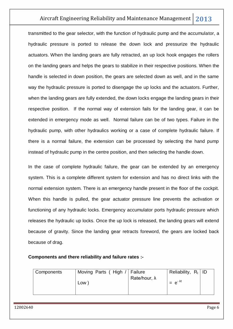
Components and there reliability and failure rates :-
Components Moving Parts ( High /
Low )
Failure
Rate/hour, λ
Reliability, Rt
= e- λt
ID
Aircraft Engineering Reliability and Maintenance Management 2013
12002640 Page 7
Solenoid V. Low 1 x 10⁻⁸ 0.99999999 1
Main Handle Low 1 x 10⁻⁶ 0.999900005 2
Gear Selector High 1 x 10⁻⁴ 0.9900498 3
Accumulator V. Low 1 x 10⁻⁸ 0.99999999 4
Hydraulic Pump High 1 x 10⁻⁴ 0.9900498 5
Hand Pump High 1 x 10⁻⁴ 0.9900498 6
Down lock and
hydraulic actuator
Moderate 3 x 10⁻⁵ 0.997000 7
Up locks and
hydraulic actuator
Moderate 3 x 10⁻⁵ 0.997000 8
Emergency
Extension handle
Low 1 x 10⁻⁶ 0.999900005 9
Emergency Gear
selector
High 1 x 10⁻⁴ 0.9900498 10
Emergency
accumulator
V. Low 1 x 10⁻⁸ 0.99999999 11
Emergency Pump High 1 x 10⁻⁴ 0.9900498 12
Landing Gear Moderate 3 x 10⁻⁵ 0.997000 13
Aircraft Engineering Reliability and Maintenance Management 2013
12002640 Page 8
ID is the identification number of each component used to describe the component for
further reference.
The reliability is calculated by the formulae Reliability, Rt = e- λt
The time is 100 hours, as more hours will give a closer value of reliability.
Quality of Evidence:-
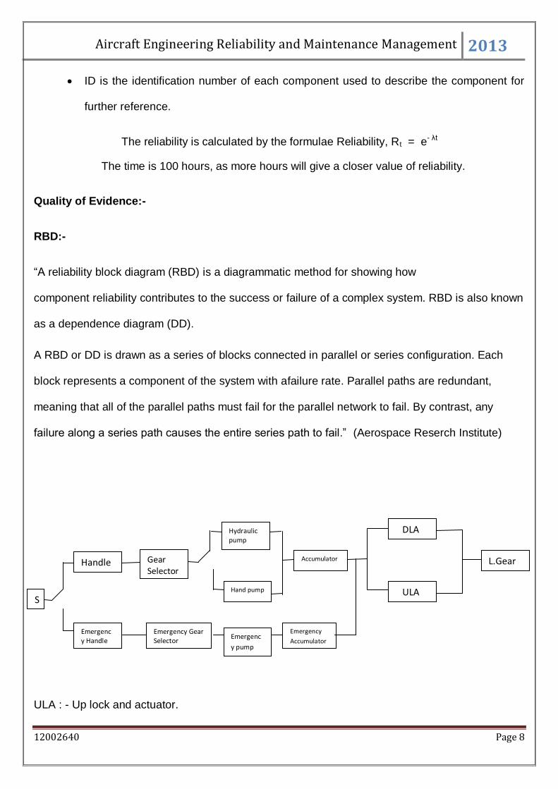
RBD:-
“A reliability block diagram (RBD) is a diagrammatic method for showing how
component reliability contributes to the success or failure of a complex system. RBD is also known
as a dependence diagram (DD).
A RBD or DD is drawn as a series of blocks connected in parallel or series configuration. Each
block represents a component of the system with afailure rate. Parallel paths are redundant,
meaning that all of the parallel paths must fail for the parallel network to fail. By contrast, any
failure along a series path causes the entire series path to fail.” (Aerospace Reserch Institute)
ULA : - Up lock and actuator.
Gear Selector
Handle
ULA
DLA
Accumulator
Hydraulic pump
Hand pump
L.Gear
Emergency Handle
Emergency Gear Selector
Emergency
Accumulator
S
Emergenc
y pump
Aircraft Engineering Reliability and Maintenance Management 2013
12002640 Page 9
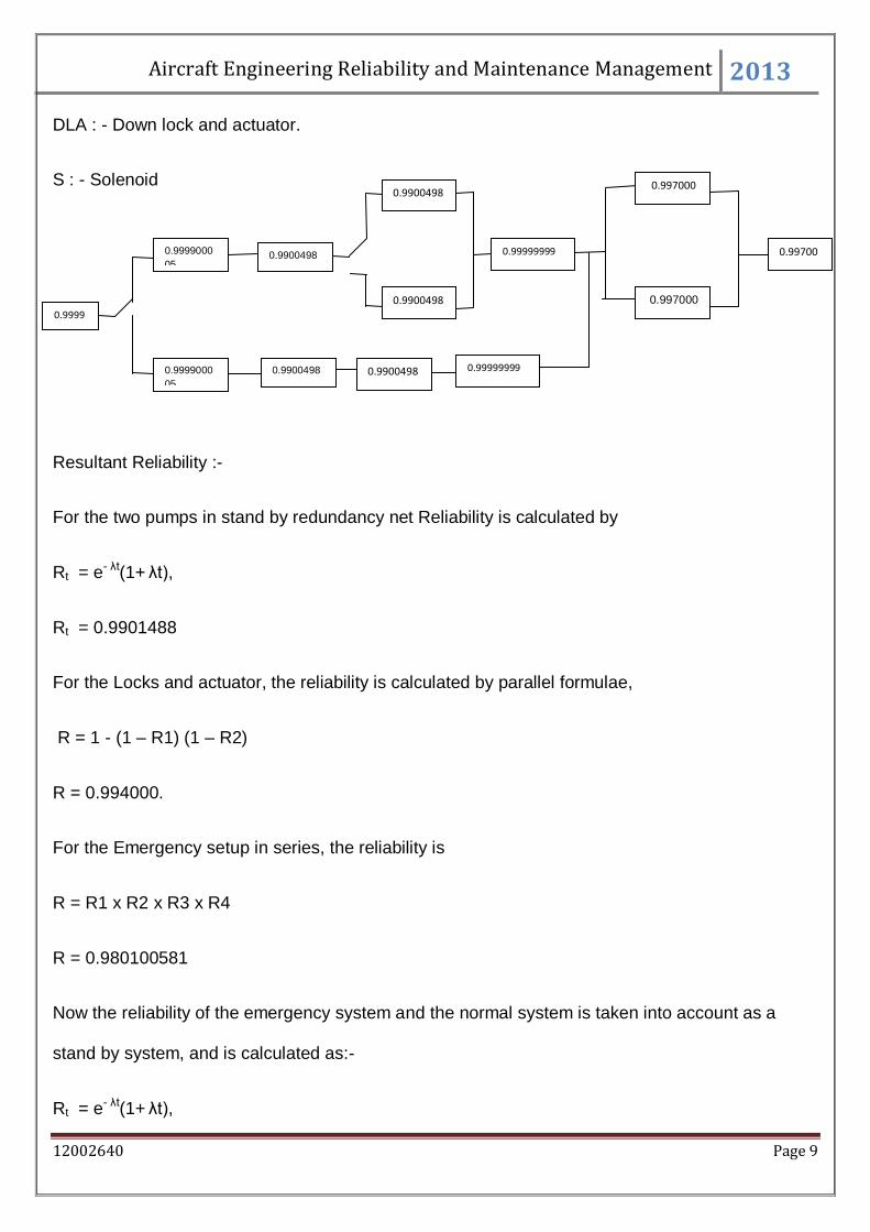
DLA : - Down lock and actuator.
S : - Solenoid
Resultant Reliability :-
For the two pumps in stand by redundancy net Reliability is calculated by
Rt = e- λt(1+ λt),
Rt = 0.9901488
For the Locks and actuator, the reliability is calculated by parallel formulae,
R = 1 - (1 – R1) (1 – R2)
R = 0.994000.
For the Emergency setup in series, the reliability is
R = R1 x R2 x R3 x R4
R = 0.980100581
Now the reliability of the emergency system and the normal system is taken into account as a
stand by system, and is calculated as:-
Rt = e- λt(1+ λt),
0.9900498 0.9999000
05
0.997000
0.997000
0.99999999
0.9900498
0.9900498
0.99700
0.9999000
05
0.9900498 0.99999999
0.9999
9999
0.9900498
Aircraft Engineering Reliability and Maintenance Management 2013
12002640 Page 10
R = 0.981080682
Now the complete can be taken in series and can be calculated by the formulae
R = R1 x R2 x R3 x ........... x Rn.
R = 0.972268605 .
Henceforth, the net resultant reliability of the normal extension and retraction is found to be
0.972268605.
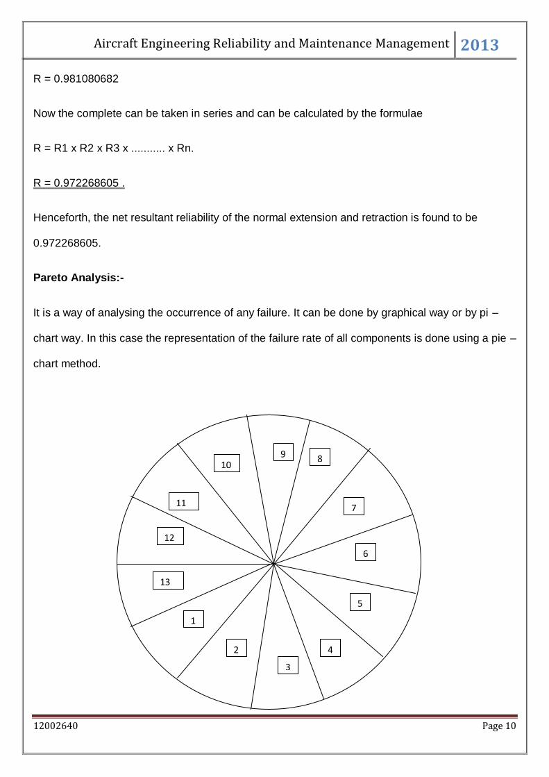
Pareto Analysis:-
It is a way of analysing the occurrence of any failure. It can be done by graphical way or by pi –
chart way. In this case the representation of the failure rate of all components is done using a pie –
chart method.
10 9 8
7 11
12
13
1
6
2
3
4
5
Aircraft Engineering Reliability and Maintenance Management 2013
12002640 Page 11
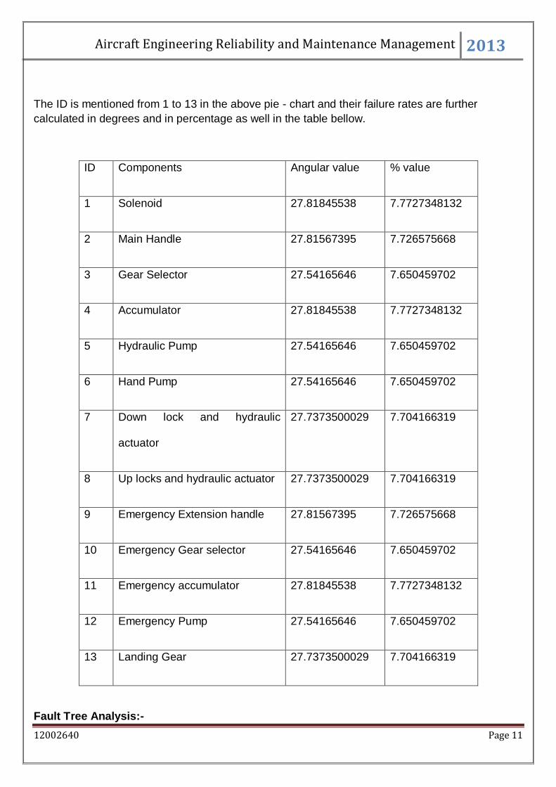
The ID is mentioned from 1 to 13 in the above pie - chart and their failure rates are further
calculated in degrees and in percentage as well in the table bellow.
ID Components Angular value % value
1 Solenoid 27.81845538 7.7727348132
2 Main Handle 27.81567395 7.726575668
3 Gear Selector 27.54165646 7.650459702
4 Accumulator 27.81845538 7.7727348132
5 Hydraulic Pump 27.54165646 7.650459702
6 Hand Pump 27.54165646 7.650459702
7 Down lock and hydraulic
actuator
27.7373500029 7.704166319
8 Up locks and hydraulic actuator 27.7373500029 7.704166319
9 Emergency Extension handle 27.81567395 7.726575668
10 Emergency Gear selector 27.54165646 7.650459702
11 Emergency accumulator 27.81845538 7.7727348132
12 Emergency Pump 27.54165646 7.650459702
13 Landing Gear 27.7373500029 7.704166319
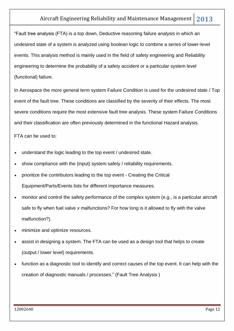
Fault Tree Analysis:-
Aircraft Engineering Reliability and Maintenance Management 2013
12002640 Page 12
“Fault tree analysis (FTA) is a top down, Deductive reasoning failure analysis in which an
undesired state of a system is analyzed using boolean logic to combine a series of lower-level
events. This analysis method is mainly used in the field of safety engineering and Reliability
engineering to determine the probability of a safety accident or a particular system level
(functional) failure.
In Aerospace the more general term system Failure Condition is used for the undesired state / Top
event of the fault tree. These conditions are classified by the severity of their effects. The most
severe conditions require the most extensive fault tree analysis. These system Failure Conditions
and their classification are often previously determined in the functional Hazard analysis.
FTA can be used to:
understand the logic leading to the top event / undesired state.
show compliance with the (input) system safety / reliability requirements.
prioritize the contributors leading to the top event - Creating the Critical
Equipment/Parts/Events lists for different importance measures.
monitor and control the safety performance of the complex system (e.g., is a particular aircraft
safe to fly when fuel valve x malfunctions? For how long is it allowed to fly with the valve
malfunction?).
minimize and optimize resources.
assist in designing a system. The FTA can be used as a design tool that helps to create
(output / lower level) requirements.
function as a diagnostic tool to identify and correct causes of the top event. It can help with the
creation of diagnostic manuals / processes.” (Fault Tree Analysis )
Aircraft Engineering Reliability and Maintenance Management 2013
12002640 Page 13
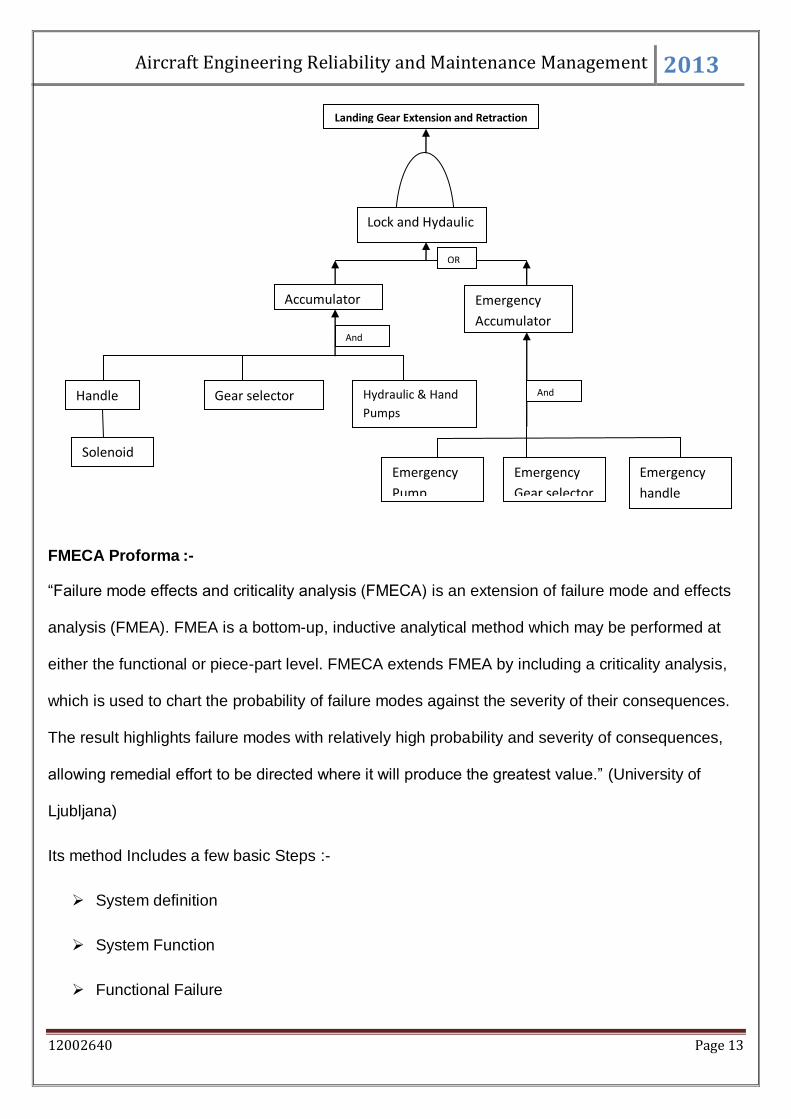
FMECA Proforma :-
“Failure mode effects and criticality analysis (FMECA) is an extension of failure mode and effects
analysis (FMEA). FMEA is a bottom-up, inductive analytical method which may be performed at
either the functional or piece-part level. FMECA extends FMEA by including a criticality analysis,
which is used to chart the probability of failure modes against the severity of their consequences.
The result highlights failure modes with relatively high probability and severity of consequences,
allowing remedial effort to be directed where it will produce the greatest value.” (University of
Ljubljana)
Its method Includes a few basic Steps :-
System definition
System Function
Functional Failure
Landing Gear Extension and Retraction
Lock and Hydaulic
Accumulator Emergency
Accumulator
Gear selector Hydraulic & Hand
Pumps
Emergency
Pump
Emergency
Gear selector
Emergency
handle
Handle
Solenoid
OR
And
And
Aircraft Engineering Reliability and Maintenance Management 2013
12002640 Page 14
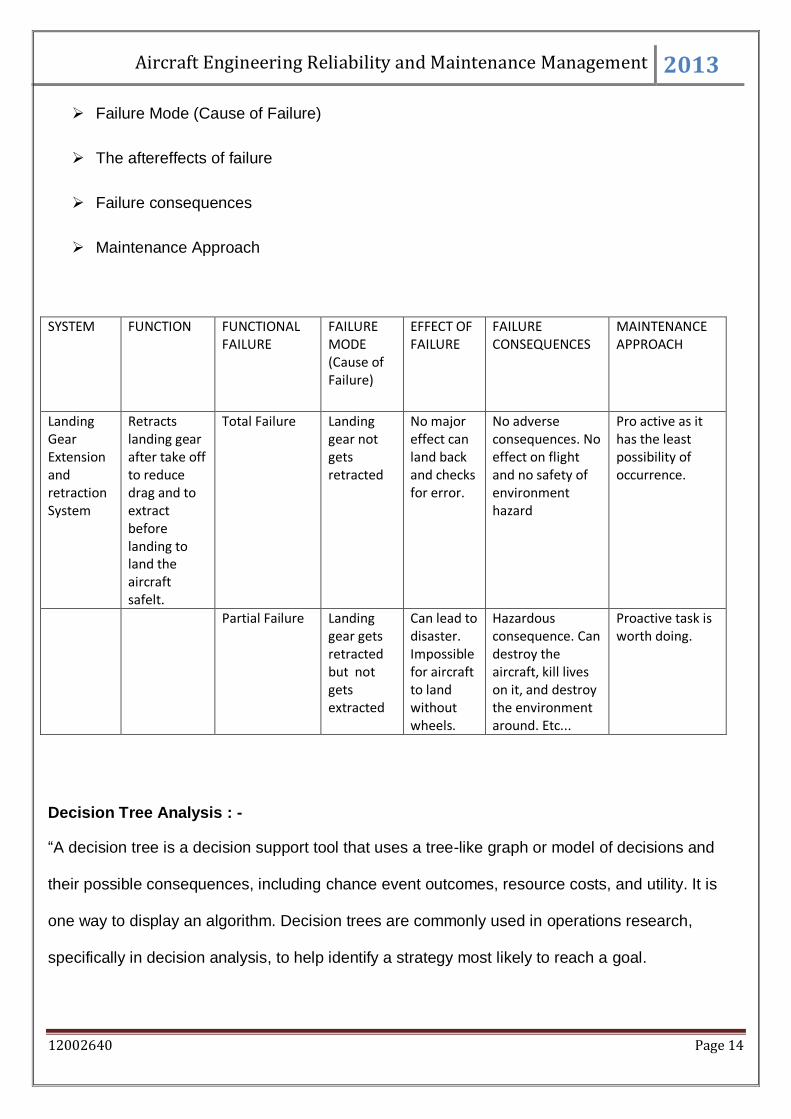
Failure Mode (Cause of Failure)
The aftereffects of failure
Failure consequences
Maintenance Approach
SYSTEM FUNCTION FUNCTIONAL FAILURE
FAILURE MODE (Cause of Failure)
EFFECT OF FAILURE
FAILURE CONSEQUENCES
MAINTENANCE APPROACH
Landing Gear Extension and retraction System
Retracts landing gear after take off to reduce drag and to extract before landing to land the aircraft safelt.
Total Failure Landing gear not gets retracted
No major effect can land back and checks for error.
No adverse consequences. No effect on flight and no safety of environment hazard
Pro active as it has the least possibility of occurrence.
Partial Failure Landing gear gets retracted but not gets extracted
Can lead to disaster. Impossible for aircraft to land without wheels.
Hazardous consequence. Can destroy the aircraft, kill lives on it, and destroy the environment around. Etc...
Proactive task is worth doing.
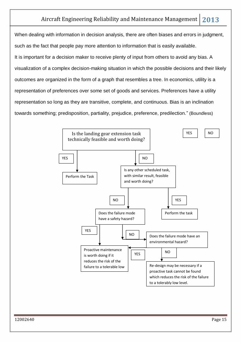
Decision Tree Analysis : -
“A decision tree is a decision support tool that uses a tree-like graph or model of decisions and
their possible consequences, including chance event outcomes, resource costs, and utility. It is
one way to display an algorithm. Decision trees are commonly used in operations research,
specifically in decision analysis, to help identify a strategy most likely to reach a goal.
Aircraft Engineering Reliability and Maintenance Management 2013
12002640 Page 15
When dealing with information in decision analysis, there are often biases and errors in judgment,
such as the fact that people pay more attention to information that is easily available.
It is important for a decision maker to receive plenty of input from others to avoid any bias. A
visualization of a complex decision-making situation in which the possible decisions and their likely
outcomes are organized in the form of a graph that resembles a tree. In economics, utility is a
representation of preferences over some set of goods and services. Preferences have a utility
representation so long as they are transitive, complete, and continuous. Bias is an inclination
towards something; predisposition, partiality, prejudice, preference, predilection.” (Boundless)
Is the landing gear extension task technically feasible and worth doing?
NO YES
Is any other scheduled task,
with similar result, feasible
and worth doing?
Perform the task
YES
YES
NO
NO
Perform the Task
YES
Does the failure mode
have a safety hazard?
Proactive maintenance
is worth doing if it
reduces the risk of the
failure to a tolerable low
level
Does the failure mode have an
environmental hazard?
Re-design may be necessary if a
proactive task cannot be found
which reduces the risk of the failure
to a tolerably low level.
YES
NO
NO
Aircraft Engineering Reliability and Maintenance Management 2013
12002640 Page 16
Conclusion : -
Evaluation of Reports Findings : -
On a simple and basic note, the objective of this report has been achieved. The Landing Gear
retraction and extension for the aircraft SAAB 340 B is highly reliable, and its reliability rate was
calculated to be 0.972268605. This also conveys about its failure rate as the failure and the
reliability adds up to 1. So the failure can be calculated by 1 – 0.972268605 = 0.027731395, and
the reliability and failure percentage being calculated as 97.2268 % and 2.7731 % respectively.
The Fault Tree Analysis explains the reason for the failure of landing gear extension and
retraction, depending on other components, and it is accomplished by use of logical gates. For
SAAB 340 B OR Gate and AND Gates are used. OR gate Fails means all of the options have
failed, whereas AND Gates fails even if one of the options have failed. The Landing Gear
Extension and Retraction fails if both the Locks and the Hydraulic Actuator fails. The Locks and
Hydraulic Actuator will fail if both the normal Accumulator and the emergency Accumulator fails,
basically it’s an OR Gate. Now the Normal Accumulator will fail, if any of the following fails : Gear
Selector; Hydraulic Pump and the Hand Pump; Handle. Further the Handle can fail if the solenoid
fails to disengage the locks. Now, Moving on to the Emergency Accumulator, it will fail if any of the
Emergency Handel or the Emergency Gear selector or the Emergency Pump fails. They are
connected via AND Gate.
FMECA is another technique use to pre determines the possible errors, the causes of it and the
after consequences. The name itself suggests about different failure modes, its effects and the
analysis of the failure, and that has been discussed in the table above. Decision Tree Analysis is
another tool which discus about the different maintenance procedures applicable for different
Failure Modes.
Maintenance Strategies : -
Aircraft Engineering Reliability and Maintenance Management 2013
12002640 Page 17
Although, the fault rate is very low, and the reliability is adjacently on a higher rate, proper
maintenance strategies should be implemented on a regular basis in order to attain the reliability
for a longer period of time. The maintenance strategies should be simple and should also be done
on a regular basis. Few of the strategies include like “All maintenance tasks must address a
specific failure mode. Use the least expensive and most effective task to maintain the asset. The
maintenance task interval will be such that it addresses the failure at the optimal point in that
asset’s failure cycle. The total cost of the failure must exceed the cost of the tasks to maintain the
asset. PM should ultimately be a time-based refurbishment, not an inspection. Failures created by
operating an asset outside of capability cannot be maintained. The assets must be redesigned.”
(reliable plant)
Wider Concept of Safety and Sustainability : -
Safety and Sustainability is the next bulls eye, the whole industry is aiming at. Sustainability is
required to bloom with one of the biggest R&D in this sector. Non sustainable form of Energy in
the form of fuel and other things are being used in an around the world in the aviation Industry.
The just don’t destroys the natural resources our green earth is having, but is also responsible for
the harmful gases that are being released in the environment. The landing gear even uses many
types of hydraulic fluids and many other day to day assets that are highly not sustainable. The
extension and retraction also produces lots of noise, by the moving parts in the gear system,
which transmits noise pollution in the environment. Be it in air, or in water, in land or in space there
is only one factor that can never be compromised, and that being the safety factor. The landing
gear extension is very necessary for the aircrafts and it is virtually and practically impossible to
land an aircraft over a paved runway. This can lead to loss of lives and property. Therefore, a few
emergency systems have been equipped in the aircraft. In case of normal Failure, Hand pump can
be used instead of Hydraulic pump, and secondly there is a complete different emergency system,
Aircraft Engineering Reliability and Maintenance Management 2013
12002640 Page 18
which comes into operation of hydraulic failure. The emergency system ensures a safety landing
of the aircraft in case of with passengers.
Related Documents
![Birdstrike involving SAAB 340B, VH-OLM, Moruya Airport, New … · ATSB Transport Safety Report [Insert Mode] Occurrence Investigation XX-YYYY-#### Final Investigation Birdstrike](https://static.cupdf.com/doc/110x72/5f33754d6c705f42b77f441f/birdstrike-involving-saab-340b-vh-olm-moruya-airport-new-atsb-transport-safety.jpg)