Reliability and Operability Committee The Connecticut Light and Power Company The United Illuminating Company Independent System Operator – New England Final Report to the Connecticut Siting Council December 20, 2004

Welcome message from author
This document is posted to help you gain knowledge. Please leave a comment to let me know what you think about it! Share it to your friends and learn new things together.
Transcript

Reliability and Operability Committee
The Connecticut Light and Power Company The United Illuminating Company
Independent System Operator – New England
Final Report to the
Connecticut Siting Council
December 20, 2004

TABLE OF CONTENTS
I. Executive Summary and Conclusion .......................................................................................1
A. Summary of Study Results ................................................................................................3
B. Summary of Evaluation of KEMA & ABB Suggestions ................................................8
C. Prior ROC Group Reports and Efforts .........................................................................10
D. Activity Since the Last Report ........................................................................................11 1. TNA Modeling and Evaluation ....................................................................................11 2, VSC HVDC Evaluation................................................................................................13 3. C-Type Filter Evaluation..............................................................................................13
II. Discussion................................................................................................................................14
A. The Uses and Limitations of Harmonic Screens and TNA Studies and Screens.......................................................................................................................14
B. Description of the ROC Study Effort and the Bases for its Determination ...............17
C. The ROC Group’s Approach to Evaluating Technological Feasibility of Underground Cable .........................................................................................................18 D. Analysis of Case 5 .............................................................................................................22
1. Description of Case 5 ...................................................................................................22 2. Analysis of Case 5 ........................................................................................................22 3. Consideration of the Potential for Additional Underground Cable..............................25
E. ABB VSC HVDC Proposal ..............................................................................................29
F. C-Type Filters ...................................................................................................................33 1. The KEMA Report......................................................................................................33 2. Analysis of KEMA Report ..........................................................................................34
III. Next Steps ..............................................................................................................................37
FINAL REPORT OF THE RELIABILITY AND OPERABILITY COMMITTEE
DECEMBER 20, 2004
2
I. Executive Summary and Conclusion
This final report of the Reliability and Operability Committee (“ROC” or “ROC
Group”) to the Connecticut Siting Council (“Council”) fulfills the goal that led to the
formation of the ROC Group by ISO New England (“ISO”), The Connecticut Light and
Power Company (“CL&P”) and The United Illuminating Company (“UI”) (CL&P and UI
are collectively referred to as “the Companies”): determining the maximum
technologically feasible use of 345-kiloVolt (“kV”) underground cable while still
enabling the Middletown to Norwalk Project (“Project”) to meet operability and
reliability requirements and electric system need for the bulk power system in Southwest
Connecticut (“SWCT”). The ROC Group has identified two configurations that it can (in
the words of the Siting Council Chairman) “stand behind.” Based upon the study results
and findings, after consultation with independent experts1, and their own experience and
judgment,, the ROC Group has identified “Case 2” and “Case 5” as technologically
feasible. Case 2 includes 13 linear miles of underground cable, between East Devon
Substation (in Milford) and Singer Substation (in Bridgeport) and Hawthorne Transition
station (in Fairfield). Case 5 includes 24 linear miles of underground cable from East
Devon Substation (in Milford) to Singer Substation (in Bridgeport), and then from Singer
Substation to the Norwalk Substation. Case 5 is technologically feasible, provided that
existing equipment is upgraded and other specific required actions occur. However, due
to the unpredictable nature of system transient response if more underground cable were
to be added between Beseck and East Devon, the ROC Group concludes that its extensive
1 The ROC Group’s principal consulting firms are GE (Schenectady, NY), PB Power (Newcastle, UK), EnerNex (Knoxville, TN); and K & R Consulting, LLC (Lenox, MA).

3
studies do not support further increments of 345-kV underground cable, beyond the 24
linear miles from East Devon to Norwalk, as technologically feasible.
A. Summary of Study Results
The report discusses the work undertaken by the ROC Group to achieve its goal.
The ROC Group considered the construction of the Project with the length of
underground cable as originally proposed (i.e., with 24 linear miles of underground
cable), and with the addition of 2, 5, 10 and 20 more miles of underground cable, up to a
total of 44 linear miles. As discussed below, the ROC Group has determined that 24
linear miles of underground 345-kV cable between East Devon and Singer, and Singer to
Norwalk, would be technologically feasible, if equipment upgrades and other mitigation
are implemented. However, the ROC Group cannot support incremental lengths of
underground cable beyond 24 miles due to the unpredictable nature of system transient
response.
In order to investigate the extent to which the Project could be constructed with
underground 345-kV cable, the ROC Group conducted extensive transient network
analyses (“TNAs”) to study the potential for temporary overvoltages (“TOVs”)2 that
could result from the introduction of such cable into the weak SWCT transmission
system. The ROC Group analyzed the results, and considered how the potential
overvoltages could be mitigated.
To expedite the review process, the ROC Group established “Cases” (i.e.,
modifications to the Project as initially proposed to the Council) with varying
combinations of overhead and underground transmission lines and varying cable and
electrical equipment technologies (e.g., synchronous condensers and C-Type filters). The 2 A TOV is a sustained overvoltage lasting more than two cycles.

4
total linear length of underground 345-kV cable in the TNA screening analyses ranged
from 4 to 44 miles.
Because the Council directed the ROC Group to determine the maximum linear
miles of underground that are technologically feasible, the studies began by focusing on
segments 3 and 4 (East Devon to Singer, and Singer to Norwalk). While the siting
process generally addresses “linear miles,” technological feasibility is affected by “circuit
miles.”3 Therefore, the ROC Group began its investigation with the locations where the
fewest circuits are required, with the intent of then moving on as the system’s tolerances
would allow. Because the Project segments west of East Devon require only two circuits,
while the Project segments east of East Devon require three circuits, maximizing linear
length of underground cable logically starts with the portion of the Project between East
Devon and Norwalk.
As discussed in this report, the ROC Group has made the following key
determinations in meeting the goal of maximizing the amount of underground cable that
is technologically feasible:
(1) The construction and operation of Alternatives A and B in the Companies’ October 2003 Application to the Council are technologically feasible, and the ROC Group would support the construction and operation of either of these configurations. In the list of studies undertaken by the ROC Group, the Alternative A route was studied in Case 2. Alternative A as studied includes the use of 13.3 linear miles (26.6 circuit miles) of underground cross-linked [?] polyethylene (“XLPE”) cable rather than high pressure fluid-filled (“HPFF”) cable as had originally been proposed. Alternative B includes the use of 4.2 linear miles4 (8.4 circuit miles) of underground XLPE cable.
(2) The Companies’ proposed route (with 24 linear miles of underground cable)
as set forth in the Companies’ October 8, 2003 Application to the Council, is
3 “Circuit miles” is the product of the number of 3-phase circuits between two points times the distance between the two points. 4 These 4.2 miles would be located in the same path – 2.1 miles from Seaview Transition Station to Singer Substation and 2.1 miles back from Singer to Seaview.
5
technologically feasible, and the ROC Group supports [?][Companies support] its construction and operation, provided that:
• XLPE cable is used rather than HPFF cable as had originally been
proposed; • replacement of approximately 1,200 surge arresters and upgrades of other
equipment are completed at about half of CL&P’s transmission substations and all of the UI transmission substations to improve the capability of the equipment to withstand TOVs; and
• more extensive changes are made to remedy local area problems (Rocky River Substation).
In the list of studies undertaken by the ROC Group, this route and technical configuration was studied as Case 5. It includes 24 linear miles (48 circuit miles) of underground cable.
Case 5 will meet the reliability objectives of the original Phase I and Phase II projects as defined in the Regional Transmission Expansion Plan (“RTEP”). While this configuration (Case 5) is more difficult to construct and operate and carries more risk than Case 2, the ROC Group supports the Case 5 configuration as that which is the maximum technologically feasible use of underground cable. Given what ISO and the Companies have learned about the impact that installing underground cable would have on the already weak system in SWCT (as discussed further below), from the standpoint of electric system design, ISO and the Companies would prefer a transmission design that contains more overhead transmission. Notwithstanding that preference, and in light of the Council’s directive, Case 5 can meet necessary reliability, operability and planning requirements.
(3) The potential for TOVs on the electric system that would exceed the withstand
capability of system elements limits the use of underground cable. An expanded SWCT system could not be considered reliable if TOVs exceeding the withstand capability of any of its elements were likely to occur under contingency conditions. The capacitance associated with underground cables increases the potential for TOVs. The ROC Group has looked carefully at the magnitude of TOVs in a number of cases, with varying combinations of overhead and underground transmission lines and varying cable and electrical equipment technologies (such as synchronous condensers and C-Type filters) and under varying operating scenarios. The linear length of underground cable in the TNA screening analyses ranged from 4 to 44 linear miles. Upon reviewing the TNA results, and considering the volatility of the system transient response and load composition variations, as well as various possible generator, capacitor, and reactor dispatches, the ROC Group has determined that the maximum length of underground cable that is technologically feasible for the Project is the 24 linear miles (48 circuit miles) of underground XLPE cable in Case 5. In the judgment of the ROC group, the addition of more

6
underground cable than the 48 circuit miles modeled in Case 5 would not enable the reliable operation of the SWCT electric system after the Bethel to Norwalk and Middletown to Norwalk Projects are complete, while still preserving some margin of operational safety to allow for present-day operations and future evolution of the SWCT system (which are likely to include generation retirements, re-powering or replacement, generator lead connections, capacitor bank installations to maintain local voltages, and 115-kV transmission line upgrades or 115-kV cable installation).
To make Case 5 technologically feasible, the Companies will have to make equipment changes on the existing system in order to increase the acceptable TOV level (measured on a “per unit” voltage basis). If TNA results indicate that a project configuration could expose the system to TOVs that exceed the capability of equipment to withstand TOVs, then that configuration would not provide adequate assurance of reliable operation of the electric system in SWCT.
In determining the limits of technological feasibility, the ROC Group relied on the
engineering and operational experience of ISO, the Companies, and their consultants5 to
model potential configurations and perform sophisticated TNA studies to predict TOV
conditions that the equipment in SWCT electric system would have to be able to
withstand, if the underground cable configurations under consideration were constructed.
The ROC Group, with the assistance of its consultants, considered the effects of the
TOVs on electric system equipment in SWCT, potential means of mitigation, and the
need to retain the ability to make future system additions.
This task was challenging, given the variability of results relating to the dynamics
of the system (capacitor dispatch, load level, etc.) and the inability to model load and
equipment characteristics precisely. Seemingly minor changes in these factors can have a
significant impact on the harmonic and transient behavior of the power system. This is a
5 The ROC Group’s consulting firms are GE (Schenectady, NY), EnerNex (Knoxville, TN), PB Power (Newcastle, UK), ABB (Raleigh, NC), EPRI Solutions, Inc., (Palo Alto, CA) Teshmont (Winnipeg, Canada); and K & R Consulting, LLC (Lenox, MA).

7
particular problem when resonances of low order harmonics can be excited by normal
system disturbances and can result in high and variable TOVs.
As discussed further in Section II of this report, the ROC Group believes that
Cases 2 and 5 do not contain any fatal flaws or insurmountable barriers that would
require major reconfiguration or project redesign in order to comply with Section 18.4 of
the Restated NEPOOL Agreement. Under Section 18.4, ISO, with the input of the
NEPOOL Reliability Committee6, conducts a review of (i) new or materially changed
plans for additions to, retirements of, or changes in the capacity of any supply and
demand-side resources or transmission facilities rated 69 kV or above, and (ii) any new
or materially changed plan for any other action to be taken that may have a significant
effect on the stability, reliability or operating characteristics of the system.
Case 2 would be the preferred alternative from an engineering viewpoint, but the
ROC Group is willing to accept the increased risks inherent in Case 5 as a matter of
compliance with Public Act 04-246. Case 5 contains increased risks that will have to be
considered by all NEPOOL Participants through the 18.4 process. While Case 5 presents
increased reliability risks, which put Case 5 at the limit of technological feasibility, the
risks can be mitigated to an extent and are considered to be manageable.
The collective conclusion of the ROC’s work is that Case 5 represents the limit of
technological feasibility. A project with additional underground cable, or cable
segments,7 beyond the 24 linear miles (48 circuit miles) between East Devon and
6 The stakeholders represented in the NEPOOL Reliability Committee are an important part of the process, as the project can affect these stakeholders’ equipment and the reliable operation of the New England electric system. The NEPOOL participants represent all the sectors of the electric industry (end users, public power, transmission owners, suppliers, and generators). 7 The risks of increased levels and volatility of TOVs as cable length is increased are compounded by increasing the number of segments of underground cable.
8
Norwalk in Case 5, would result in unacceptable reliability and operability risks. These
risks include unpredictable system responses during contingencies, which increase the
likelihood of exceeding the magnitude and duration of TOV limits of system equipment.
These issues would exist even after upgrades of existing equipment have been made to
make Case 5 acceptable.
B. Summary of Evaluation of KEMA & ABB Suggestions
In October of this year, the Council’s independent consultant, KEMA, had
preliminarily recommended the use of C-Type filters as a possible means of increasing
the amount of underground cable that could be installed. KEMA’s recommendation was
based upon harmonic screening studies that modeled an intact SWCT system operating
under normal conditions, with no contingency analysis. Accordingly, KEMA
recommended that TNAs would need to be performed to confirm that C-Type filters
would enable additional underground cable. As discussed in Section II.F of this report,
the ROC Group commissioned a TNA screening study of a system configuration with
underground cable, with and without C-Type filters tuned to the third harmonic as
suggested by KEMA. The study included contingency analysis. Although the addition
of C-Type filters could improve the performance characteristics of an intact system under
normal operating conditions, TOVs were worse under many contingent conditions with
C-Type filters added to the system than without them. It should be noted that virtually all
system fault events which can produce a TOV result in the system operating in contingent
situation with the faulted system element (e.g., line, cable, or transformer) necessarily
removed from the system. In addition, the C-Type filters can only be switched into the
system when the capacitive MVARs they produce are needed and can be accepted by the

9
system without excessively increasing the steady-state voltage. TNA results show that
high TOVs can also occur for light load conditions where the C-Type filters cannot be
used. Accordingly, the ROC Group does not support the use of C-Type filters as a
generic resolution to TOV problems.
Also in October, ABB proposed that the use of its voltage source converter high
voltage direct current (“VSC HVDC”) technology8 for underground cable between
Beseck Switching Station and Norwalk Substation. As discussed in Section II.E of this
report, the ROC Group has determined that the ABB proposal does not meet the electric
system criteria established for this Project. The use of VSC HVDC as proposed by ABB
would add unacceptable complexity to the system; require reliance on unproven
operating procedures and control technology; prohibit the installation of new merchant
generation unless VSC HVDC terminals were incorporated into the generator lead; limit
future expansion of the electric grid to serve customer load; and render the backbone of
the SWCT transmission system dependent on new technology available only from one
source – ABB, the consultant/manufacturer that recommends its use. Moreover, the ROC
Group estimates that the full cost of the ABB VSC HVDC proposal would be
approximately double the cost of the Companies’ proposed project alternative (Case 5
with XLPE). Finally, because HVDC operates differently than AC facilities, the ABB
proposal would face great challenges from NEPOOL Participants with respect to
receiving regional cost support.
8 The ABB proposal uses VSC HVDC and HVDC Light®, ABB’s trademarked name for VSC HVDC, interchangeably.

10
C. Prior ROC Group Reports and Efforts
The ROC Group was formed in June 2004 to identify and consider potential
Project modifications and transmission designs that would enable the maximum
technologically feasible use of underground cable for the Project, consistent with
operability and reliability requirements and electric system need.
The initial ROC report, submitted to the Council on August 16, 2004 (the “August
Report”), provided a summary of the ROC Group’s work to that date in considering
potential project modifications that would enable the maximum feasible use of 345-kV
underground cable for the Project consistent with operability and reliability requirements
and electric system need. It reported that of more than a dozen cases studied, only Case
7, involving the unprecedented use of multiple static synchronous compensators
(“STATCOMs”) in close electrical proximity to each other, had passed a preliminary
frequency scan analysis performed by the Companies’ consultant, GE Power Systems
Energy Consulting (“GE”). The August Report, while expressing reservations
concerning the technological and operational complexity of Case 7, recommended that it
be examined further.
On October 8, 2004 the ROC Group submitted an interim report to the Council
(the “October Report”). The October Report addressed three potential system additions:
Case 5, Case 7 and the use of VSC HVDC for the Project (as had been proposed by
ABB). The October Report reflected the ROC Group’s concerns that the modifications
that are part of Case 7 would be undesirably complex because, in part, control of a large
number of STATCOMs in close electrical proximity represents additional design,
reliability, and operational challenges, (October Report, page 5). The ROC Group also

11
stated that STATCOM technology is not a mature, reliable technology for this application
and reported that, based on further review, Case 7 would not result in a reliable solution
to the electric needs of SWCT. Id.
The October Report noted that the ROC Group had reinstituted the analysis of
Case 5 to look in further detail at its potential for overvoltages and that, while the
preliminary TNA results of Case 5 were troubling, further evaluation of Case 5 would be
conducted. Lastly, based on preliminary review of reports received from ABB promoting
the use of VSC HVDC,9 the October Report expressed serious concern regarding the
technical feasibility of ABB’s proposal for the unprecedented and unproven use of
complex control schemes and technology in combination with ABB’s VSC HVDC to
address the electric needs of SWCT. The October Report stated the ROC Group’s
intention to examine and evaluate the ABB reports further before reaching a final
conclusion regarding ABB’s VSC HVDC proposal (the “VSC HVDC Proposal”).
D. Activity Since the Last Report
1. TNA Modeling and Evaluation
The October Report indicated the ROC Group’s intention to continue its
evaluation of troubling TOV issues identified in Case 5 in order to understand better the
causes of the unacceptable voltage levels identified by GE in the initial Case 5 study
results, and to seek solutions to these causes with the goal of maximizing the amount of
underground cable used in the Project. To assist in its investigation of the problems
identified in GE’s preliminary Case 5 analysis, and to investigate the potential of
9 The ABB reports were attached to the October Report and consisted of a “Middletown – Norwalk Transmission Project Technical Description of VSC HVDC Converter and Cable Technology,” dated October 1, 2004, and a “Middletown – Norwalk Transmission Project VSC HVDC System Feasibility Study,” dated October 3, 2004.

12
additional underground cable beyond that in Case 5, the ROC Group retained additional
consulting firms to perform separate modeling analyses.
The first objective of these additional studies was to determine if the same or
similar problems could be replicated in a separate modeling analysis and then mitigated.
Retaining multiple teams of consultants was necessary due to the unprecedented nature of
the assignment resulting from P.A. 04-246: how to maximize the use of 345-kV
underground cable in a weak bulk power system, and how to conclude that analysis given
the immediate and pressing need for new transmission in SWCT.
• The ROC Group managed the consultants’ work so as to enable a comparison of each consultant team’s TNA work with that of the other teams. The ROC Group created a series of fault simulation cases that examined the following alternative scenarios: The Project as proposed, but with XLPE substituted for HPFF cables –(Case 5, which has 24 miles underground)
• Alternative A with XLPE substituted for HPFF cable between East Devon and Singer – (Case 2, which has13.3 miles underground)
• Alternative B ( Case 1, which has 4 miles of XLPE cable underground) • Case 5 plus an additional approximately 5 miles underground – Case 5B • Case 5 plus an additional approximately 10 miles underground – Case 5C • Case 5 plus an additional approximately 20 miles underground – Case 5A • Cases 5 and 5A with the addition of C-Type filters tuned to the third
harmonic, as suggested by KEMA
A large number of analyses were conducted to evaluate the TOV performance of
these various alternatives over a wide range of load level and system conditions. The
focus of this effort was to find a solution that had no fatal flaws from the perspective of
planning a reliable and operable system. A list of the TNA studies and screens upon
which the ROC Group relied in reaching the conclusions expressed in this report appears
at the end of the text of this report. The results of these studies are included as
Appendices D and E.

13
2. VSC HVDC Evaluation
The ROC Group has completed its further consideration of the proposal for a
complex control system in combination with ABB’s VSC HVDC technology. While
point to point VSC HVDC might address part of the load growth in SWCT, the ROC
Group has concluded that ABB’s VSC HVDC proposal does not meet the electric system
needs and would result in unacceptable reliability and operability risks.
3. C-Type Filter Evaluation
Finally, the ROC Group has studied KEMA’s suggestion that the substitution of
C-Type filters tuned to the third harmonic for capacitors at various SWCT substations
could expand the amount of underground cable that would be technologically feasible on
the SWCT system. KEMA supported this suggestion with harmonic screening studies
that showed improved harmonic conditions on an intact SWCT system under normal
operating conditions with the addition of C-Type filters. In order to try to understand
better KEMA’s suggestion, the ROC Group sought help from industry experts in several
countries (including two members of the IEEE Harmonics Working Group). None of
these experts could advise the ROC Group on the use of C-Type filters to maximize
underground cable, which they considered purely theoretical. However, the ROC Group
was able to model the results of incorporating C-Type filters tuned to the third harmonic
into the SWCT system at the locations identified by KEMA. The KEMA report, which
did not study the use of C-Type filters under contingency conditions, appropriately stated
that final answers on their proposal’s acceptability would depend on the results of
detailed transient analyses. The ROC’s consultants have completed those studies and
found the filters to be ineffective at mitigating TOVs under contingency conditions.
14
Indeed, under many contingencies, the TOVs were higher with the addition of C-Type
filters.
II. Discussion
A. The Uses and Limitations of Harmonic Screens and TNA Studies and Screens
Frequency domain screening (also called harmonic screening) studies are
designed to provide information about a system characteristic -- its impedance at each of
the harmonic frequencies -- that can result in overvoltages on substation and other
switching equipment when currents at those frequencies are produced.
These studies are concerned primarily with impedances at “harmonic”
frequencies. Power systems in North America are designed to operate at a frequency of
60 Hz, which is called the “fundamental frequency.” Current that is produced by
generators is delivered to the generator bus at that frequency. But currents also flow on
the system at other frequencies, which are multiples of the fundamental frequency. These
currents are called harmonic currents, or harmonics for short. Following system faults or
transformer energization, the largest magnitude of these frequencies occurs at low order
multiples of the power system frequency (120, 180, and 240 Hz, for example, also called
the second, third, and fourth harmonic frequencies).
Frequency domain screening can be used to analyze impedances both under
normal system operating conditions and in the event of contingencies such as the
unplanned loss of one or more system elements. They provide information as to the
likely impedance at different frequencies and can identify “resonances” – frequencies at
which the impedance is much higher than what would be expected without system
capacitance. Because the magnitude of harmonic currents during disturbances tends to be

15
greatest at the second and third order harmonics, resonances at and near those levels are a
concern.
The point of first resonance will be lower when there is more capacitance on the
system or when the system is weaker (less generation and/or less transmission capacity in
the area than “normal”). When system elements that increase the capacitance of the
system (cables and capacitors) are added, the primary resonance frequency moves lower.
Since the main source of disturbing current under fault conditions is due to transformer
saturation and the highest currents produced are at low frequencies, in general the highest
TOVs are created when the system resonance is lowest. This is the fundamental reason
why power engineers try to keep the primary resonance of the power system from getting
too low. It is also the reason why the introduction of a large source of capacitance – such
as underground cables – into a weak transmission system raises concerns related to
harmonic resonance of the system, and warrants investigation by harmonic screening
studies to identify impedances that could interact with low order harmonic currents.
SWCT has such an electrically weak system – there are relatively few generation
resources in the immediate vicinity of where the load is concentrated, and there are fewer
strong transmission paths from outside sources to the area of load concentration (hence
the need for this project).
However, harmonic screening studies do not model the actual voltages to which
system equipment will be subjected. They model impedances. As set forth in Ohm’s
law, voltage is equal to the current multiplied by the impedance of the system. There can
be high impedance at a specific frequency, but if there is not a significant source of
excitation current at that frequency, there will not be a high voltage concern. Similarly, if

16
the impedance at a given frequency is low enough, even if there is a large amount of
current at that frequency, the current does not produce an overvoltage of concern.
A TNA, also called a time domain analysis, is much more elaborate than a
harmonic screen. A TNA models transient events as they would evolve, and thus
considers the currents and impedances at all of the relevant frequencies, simultaneously,
under a wide array of system conditions and events. It thus provides detailed information
about the voltages that will be produced on a particular system by the modeled conditions
and events. Such studies are particularly concerned with very short term overvoltages
(TOVs) lasting from a few cycles (each cycle is one 60th of a second) to seconds. These
TOVs can cause system elements, primarily substation and switching equipment, to fail,
with serious consequences. In particular, transformer in-rush currents associated with
energization after fault clearing can inject high levels of harmonic currents into the
system, particularly since many transformers in an area can be energized simultaneously
after a fault.
However, it is impractical to model all of the potential system conditions (e.g., the
magnitude and characteristics of the load, the clearing times of breakers, the strength of
the system, the operating condition of capacitors and synchronous condensers or
STATCOMs, and the status of lines and generators) that could produce TOVs on the
system. Many contingent permutations can alter the system frequency response so that at
some point over the life of the design, the situation of high impedance and high current is
likely to occur.
Before the ROC Group was formed, GE performed several harmonic screening
studies of the SWCT system to determine the impedances of the intact system under
17
normal operating conditions. The studies performed by KEMA that modeled
underground cable and C-Type filters were of that type as well. The studies
commissioned by the ROC Group that this report reviews were primarily TNAs.
Because harmonic screens are less time consuming than TNAs, they are often
used as “gates” to identify system configurations that merit further analysis. System
configurations that appear to pass through the gate will still need to be analyzed further in
a TNA before they can be constructed. It is also possible that a TNA can show a
configuration to be acceptable if particular mitigation measures are adopted, even though
it appears in a harmonic screen to be on the borderline of unacceptable risk. That was the
case, for instance, with Case 5.
B. Description of the ROC Study Effort and the Bases for its Determination
In the summer of 2004, ISO contracted PB Power to develop an Electromagnetic
Transients Program (“EMTP”) model of SWCT in order to validate the results of the GE
testing. Concurrently, GE was continuing its evaluation of frequency scans and TNAs
for various system configurations as requested by the Companies. Once the ROC Group
began focusing on TNAs, the demands on the resources of the GE team increased
significantly. Therefore, the ROC Group began an international search for companies
with both the expertise and available staff to run the required simulations in accordance
with the ambitious schedule required to support the Project.
Model testing revealed changes that needed to be made to better represent the
SWCT system and each consulting firm modified its system models accordingly.
Additionally, since the Companies and ISO progressively refined the study conditions,
the required testing conditions were also refined. All of the consultants began submitting

18
results for various system configurations to the ROC Group for review. The ROC
Group’s own technical staff coordinated all of the studies and analyzed their results.
Because the various consultants were not testing similar configurations, it was initially
quite difficult to determine which differences were due to system configuration and
which were due to modeling differences. Two teams – Teshmont and EPRI Solutions -
showed significant and inexplicable differences in their results. In the case of Teshmont,
the results either showed extremely high voltages with no decay, or what would be
considered surprisingly low voltages. EPRI’s results also showed low voltages, many of
which would be indicative of a voltage collapse. Thus their results were not incorporated
in the final ROC Group report. In order to maximize the number of cases considered, the
ROC group decided to concentrate the work in the teams that first proved capable of
producing high quality results in relatively short times that could be meaningfully
analyzed along with one another.
The primary assignment of the ABB teams was to evaluate the Bethel to Norwalk
Project to provide an independent verification as to the acceptability of that design.
ABB’s work on the Project, was limited and not significant to the ROC Group’s
evaluation of Case 5 and additional underground cable.
C. The ROC Group’s Approach to Evaluating Technological Feasibility of Underground Cable
In order to maximize underground 345-kV construction, the ROC Group first
considered whether it could accept a very significant change from the Companies’ initial
proposal – the use of a new cable technology. In their application, the Companies
proposed to use HPFF underground cable, because of its proven reliability. As the
Council noted in Docket 217, XLPE cable is a newer and still maturing technology at the
19
345-kV voltage level. However, the capacitance of this cable is only about 60% of that
of HPFF cable. Since the capacitance of the system is a significant driver of TOVs,
XLPE cable can reduce the negative effect of capacitance compared to HPFF cable. The
harmonic screens and TNA studies that were performed before the ROC Group was
formed indicated that the Companies’ original proposal, with HPFF cable, would produce
unacceptable harmonic resonances. A change to XLPE cable could potentially preserve
the originally proposed underground route.
After considerable deliberation, the ROC Group made an engineering judgment
that, particularly in light of performance statistics that have become available since the
Docket 217 hearings, XLPE cable (although not as reliable as HPFF cable) will be
reliable enough for the use specified in Case 5, and that the greater risk of employing this
cable can be accepted in order to comply with the mandate of P.A. 04-246 to maximize
345-kV underground construction.
Attached as an Appendix to this report is a technical paper10 prepared by
Northeast Utilities Service Companies’ engineering staff explaining in detail the
considerations supporting the ROC Group’s engineering judgment to support the use of
345-kV XLPE cable.
The ROC Group analyzed the TOVs that appeared in the results of the TNA
studies of the various system configurations that included XLPE cable. Each piece of
electric transmission and distribution equipment has a capability to withstand a rated
range of overvoltages for a short period of time. In order to determine if the system
would withstand – or could be made to withstand – the overvoltage conditions of the kind
10 D.W. Forrest & R.I. Mosier, “Discussion Of Cross-Linked Polyethylene Insulated Cables For Underground Portions of The Middletown-Norwalk 345 kV Projects,” December 20, 2004.
20
the TNA studies show could occur, the Companies determined the withstand capabilities
of the equipment that is currently installed in the system and the withstand capabilities of
the equipment that is contemplated for the proposed project. This effort involved the
identification and rating of each piece of equipment in the SWCT substations and
switching stations, and the consideration of the withstand capabilities of each piece of
such equipment. The Companies then identified the equipment that had insufficient
capability to withstand the overvoltage conditions and considered whether that equipment
could be replaced with equipment that had a higher withstand capability without causing
problems elsewhere on the system. A paper entitled “Temporary Overvoltage Equipment
Limits – Summary Report” dated December 17, 2004, prepared by a ROC Group
consultant, K & R Consulting, LLC (the “Temporary Overvoltage Report”), explaining
this investigation of TOV limits and its results is included as Appendix B to this report.
It was clear that the existing equipment in SWCT could not tolerate the TOVs
shown in most of the TNA results – including those for Case 5. In considering how the
withstand capability of critical system elements could be upgraded to handle these TOVs,
the ROC Group was required to exercise engineering judgment, with the assistance of its
consultants. No system should be designed with an expectation that it will be operated
for an indefinite time at or near the limit of tolerance of new system equipment, since
equipment can degrade over time. Moreover, all of the TNA models incorporated
assumptions as to load characteristics that are necessarily based in part on engineering
judgment rather than definitive data. In any event, these load attributes will change over
time. Even after rigorous attempts to synchronize the modeling techniques and
assumptions using the same model base, there remained some variability among different

21
consultants’ results. Finally, system conditions will change, including the possible
addition of generators and substation capacitor banks. Perhaps most important, it is
impossible to be sure that the TNA studies and screens have definitively identified the
worst TOV cases that the system will be required to withstand. Some margin of safety is
prudent to account for system variability.
As explained in the paper prepared by K & R Consulting11, the Companies
determined that the limiting factors for TOVs to be as follows:
Table 1
Typical 84 kV MCOV and 235 kV MCOV Surge Arrester Temporary Overvoltage Limits 2 cycles 6 cycles 30 cycles 1 second
115 kV (84 kV MCOV) 2.03 1.98 1.92 1.89
345 kV (235 kV MCOV) 1.85 1.80 1.74 1.71
As illustrated in the table below, together with their consultants, the ROC Group
then identified an operating margin to account for the elements of system variability to
address sensitivities associated with additional substation capacitor banks, additional
generation, and loads. The ROC Group assessed the components of the required system
variability margin as follows12:
Table 2 - TOV Margins
Factor Margin Margin Squared Load levels and damping characteristics 0.2 0.04 Generation dispatch 0.1 0.01 Capacitor dispatch, and LV capacitors 0.1 0.01 Sum of Squares: 0.06 Total Margin: 0.25
11 See Appendix B, page 7. 12 See Appendix C.
22
The group then evaluated the TNA results according to these criteria. Cases with
substantial numbers of TOVs above or within the variability margin were deemed
unacceptable. Results of studies of TNA screens of configurations with additional cable
beyond that incorporated in Case 5 were evaluated in light of the recognition that the full
TNA study of Case 5 showed it to be at the margin of acceptable risk.
D. Analysis of Case 5
1. Description of Case 5
Case 5 is described as follows: Start with the proposed M-N Project, replace both 345-kV HPFF cables between East Devon and Singer with XLPE, replace both 345-kV HPFF cables between Singer and Norwalk with XLPE, and remove one of the 345-kV HPFF cables in the Bethel to Norwalk Project from service.
This description reflects an assumption that, under light and moderate load
conditions, the Bethel to Norwalk system will be operated with only one of its two 345-
kV HPFF cables in service, so as to reduce system capacitance. Both HPFF cables are
likely to be in operation under heavy generation conditions, and may be operated then
without a problem, since more local generation would be in service and far greater load
would be connected to the system, which acts to dampen transients and TOVs. Even
when only one cable is in operation during light load periods, the other will be able to be
switched into service following a system contingency.
2. Analysis of Case 5
In order to evaluate a maximum number of alternatives, ISO contracted with PB
Power to construct its own TNA model of the SWCT system and then benchmark Case 5
to confirm study results reported by GE. It took PB Power several months to build the
model and thoroughly document it for use by the ROC Group’s other consultants. PB

23
Power then re-ran Case 5 with results that were somewhat similar to GE’s, but had larger
than expected differences with respect to the degree and duration of TOVs.
The ROC Group reviewed all of the modeling assumptions (including, among
others, assumptions relating to transformer modeling, level and type of load
characteristics, and cable parameters). Assumptions relating to the load levels in SWCT
could have a significant impact on study results.13 The ROC Group determined that,
notwithstanding that any load assumption could be a poor predictor of loads that would
actually occur on the system, a load assumption should be included in the analysis, and
the ROC Group directed that Case 5 studies be re-examined with modified load
assumptions. The Case 5 studies were then run with the load representation changed to
40%, 50% and 70% of peak load levels. Limited testing was also done at a 30% load
level. GE results (under these load representations) and PB Power results are similar.
Concurrently with the consultants’ TNA studies, the Companies’ engineers
determined the relevant TOV withstand and duration limits that could be achieved with
massive equipment upgrades. These upgrades will probably include the replacement of
as many as 1,200 surge arresters at approximately 50% of the substations on the CL&P
transmission system, and at virtually all of the UI transmission substations. Other
substation equipment upgrades are also likely to be required. The ROC Group overlaid
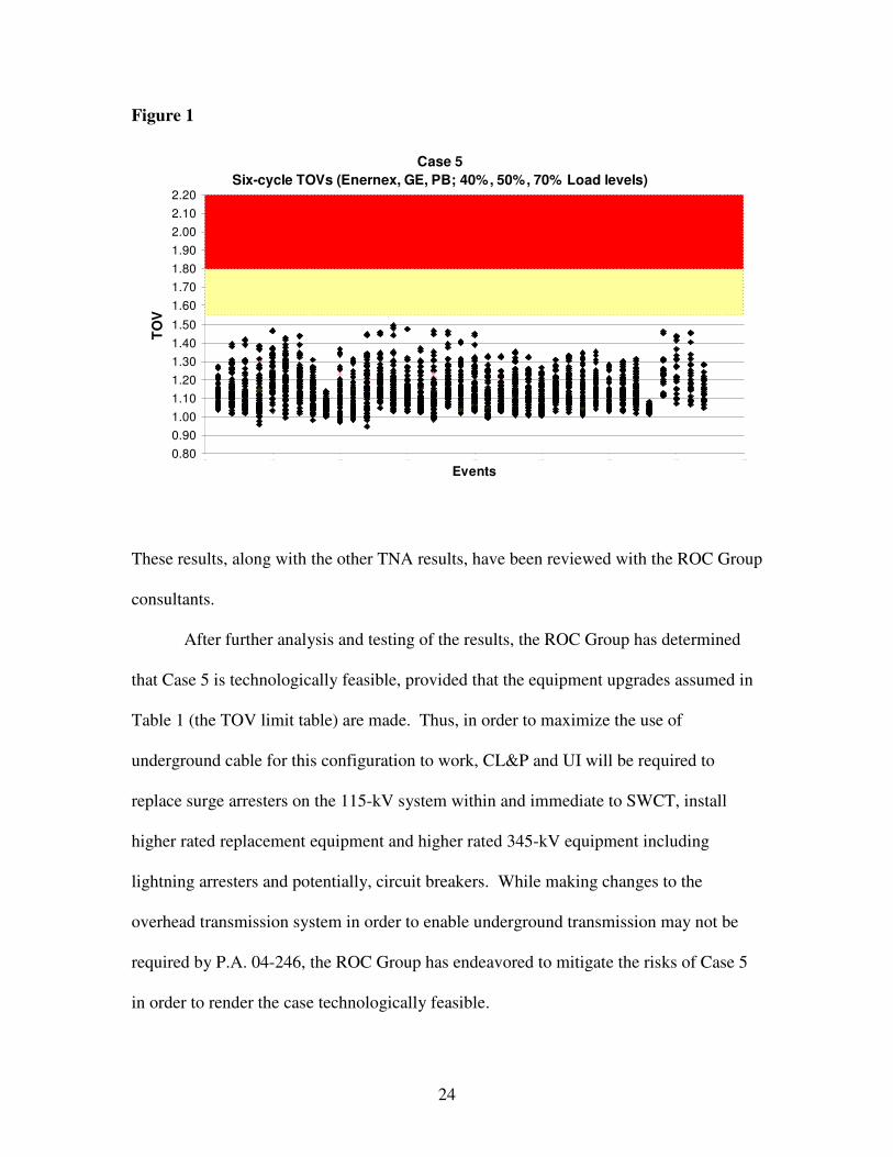
the results of the Case 5 TNAs on those limits with the following results:
13 GE advised that it conducts all of its TNA studies using an extremely low load level, and GE expressed its belief that such an approach provides the best study results. In support of this advice, GE referred to CIGRE paper 33-210 (1990), “Temporary Overvoltages: Causes, Effects, and Evaluation.” As that paper states, “Actual data on loads and their effect on TOV are scarce.” Therefore, the construction of a load component in a TNA model is arguably somewhat arbitrary, and the use of only a nominal load assumption produces the most conservative and therefore reliable result. The load modeling issue is discussed in an attachment to the GE report on Case 5, Appendix D to this report.
24
Figure 1
These results, along with the other TNA results, have been reviewed with the ROC Group
consultants.
After further analysis and testing of the results, the ROC Group has determined
that Case 5 is technologically feasible, provided that the equipment upgrades assumed in
Table 1 (the TOV limit table) are made. Thus, in order to maximize the use of
underground cable for this configuration to work, CL&P and UI will be required to
replace surge arresters on the 115-kV system within and immediate to SWCT, install
higher rated replacement equipment and higher rated 345-kV equipment including
lightning arresters and potentially, circuit breakers. While making changes to the
overhead transmission system in order to enable underground transmission may not be
required by P.A. 04-246, the ROC Group has endeavored to mitigate the risks of Case 5
in order to render the case technologically feasible.
Case 5Six-cycle TOVs (Enernex, GE, PB; 40%, 50%, 70% Load levels)
0.800.901.001.101.201.301.401.50
1.601.701.801.902.002.102.20
0 .0 0 5 .0 0 1 0 .0 0 1 5 .0 0 2 0 .0 0 2 5 .0 0 3 0 .0 0 3 5 .0 0 4 0 .0 0
Events
TOV

25
3. Consideration of the Potential for Additional Underground Cable
The ROC Group’s exhaustive examination of underground configurations
included studies, analyses and discussion of the 24 linear miles (48 circuit miles) of
XLPE cable from East Devon to Norwalk in Case 5. In order to analyze the potential for
additional underground cable, incremental to the cable in Case 5, the ROC Group asked
its core consultants14 to study Case 5 plus incremental underground lengths from East
Devon toward Beseck. The ROC Group has considered Case 5 with an additional 2, 5,
10 and 20 linear miles of underground cable from East Devon toward Beseck. Based
upon the study results of these additional cases, comparisons to the Case 5 results,
discussions with the consultants who modeled these cases, and the experience of the ROC
Group members and ISO staff, the ROC Group has concluded that Case 5 (with 48 circuit
miles of underground cable) is at the limit of technological feasibility, and that addition
of more cable to the Project from East Devon toward Beseck would impose unacceptable
risk.
Supporting data and analysis are included in the EnerNex report included as
Appendix C. It reviews the analysis of Case 5 (base case) and Case 5 + 5, 10, and 20
additional linear miles of underground cable. The GE report of Case 5 (base case) and
Case 5 + 2, 5 additional linear miles of underground is included as Appendix D. As
stated in the EnerNex report, analysis of the study results showed that:
• As more cable is added, the first resonant frequency of the system decreases. • As more cable segments are added with their associated shunt compensating
reactors, additional local resonances are created in addition to the main resonance point.
• More complicated dynamic behaviors occur as we add more capacitance.
14 GE, PB Power, and EnerNex.

26
• At key 345-kV and 115-kV buses throughout Southwest Connecticut, the worst TOVs increase as more cable is added.
• The impact of load, capacitor dispatch, and other topology changes seem to be more pronounced as more cable or capacitance is added (e.g. more variability in results – sometimes large reductions in TOVs, sometimes large increases in TOVs).
Certain TOV results relating to additional underground have been
counterintuitive, complex and difficult to understand. The ROC Group asked GE and
EnerNex, the consultants most familiar with the studies and results, to consider the results
further in order to advise the ROC Group. A cursory review of the results could lead one
to believe that the addition of more cable beyond the length of 5 miles between East
Devon and Beseck would actually result in improved system performance. These results
are counterintuitive and have been determined not to be representative of what could
happen to the transmission system in SWCT.
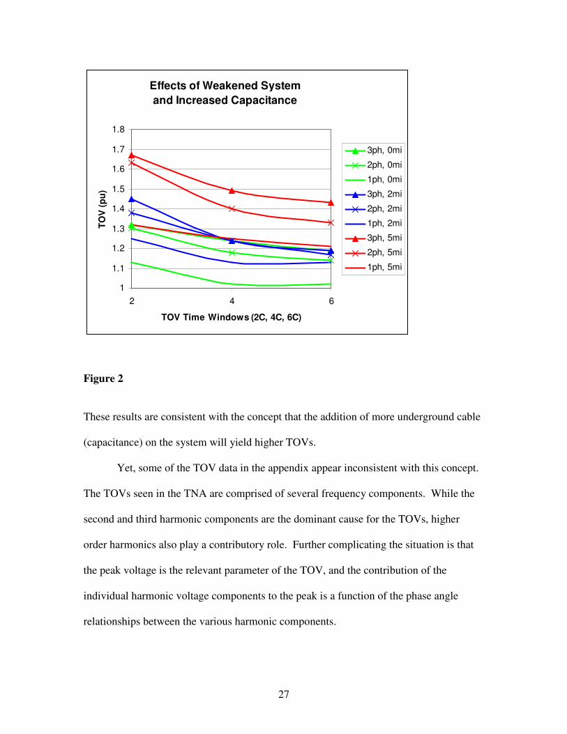
Further investigation began with a review of the GE data for the addition of small
amounts of cable between East Devon and Beseck. Figure 2 below shows the effect on
TOVs of faults on the Plumtree – Long Mountain line with the base case (Case 5 + 0) and
with the addition of 2 and 5 miles (linear length) of cable.
27
Effects of Weakened System and Increased Capacitance
1
1.1
1.2
1.3
1.4
1.5
1.6
1.7
1.8
2 4 6
TOV Time Windows (2C, 4C, 6C)
TOV
(pu)
3ph, 0mi
2ph, 0mi
1ph, 0mi
3ph, 2mi
2ph, 2mi
1ph, 2mi
3ph, 5mi
2ph, 5mi
1ph, 5mi
Figure 2
These results are consistent with the concept that the addition of more underground cable
(capacitance) on the system will yield higher TOVs.
Yet, some of the TOV data in the appendix appear inconsistent with this concept.
The TOVs seen in the TNA are comprised of several frequency components. While the
second and third harmonic components are the dominant cause for the TOVs, higher
order harmonics also play a contributory role. Further complicating the situation is that
the peak voltage is the relevant parameter of the TOV, and the contribution of the
individual harmonic voltage components to the peak is a function of the phase angle
relationships between the various harmonic components.

28
To further the ROC group’s understanding of the results, EnerNex performed
frequency scans at the Norwalk 345-kV bus for a given system condition with the
Plumtree to Long Mountain line out of service. These frequency scans demonstrate that
with five miles of cable added between Beseck and East Devon (i.e., Case 5 + 5), a
second resonance point begins to develop at around the fourth harmonic (240 Hz). The
creation of this second point of high resonance explains why high TOVs occur at 5 miles,
since the harmonic voltages are additive. However, the frequency scans also show that
the second resonance point still exists with 10 and 20 miles of additional cable, but is
shifting to a lower frequency for the conditions tested.
This is extremely troubling from the standpoint of system planning, operation and
reliability, since the TOV results demonstrate extreme volatility due to the frequency of
this second resonance point. Very small system changes (e.g., capacitors, generators,
load level and type) can cause this second resonance point to increase or decrease in
frequency. Therefore, the TOV results for Case 5 + ten and twenty miles, which
appeared to show lower TOVs, can be misleading. These are only a snapshot of a given
set of system conditions, and do not capture the full range of potential operating
situations.
Changes in operating conditions can readily shift the resonance points and result
in much higher TOVs. The addition of this second resonance point is seen when there
are additional amounts of cable incremental to the cable included in Case 5 (base case).
Because of the potential for extreme volatility, the ROC group believes that a system
with additional underground cable, beyond the 24 linear miles from East Devon to
Norwalk, would not be technologically feasible.

29
E. ABB VSC HVDC Proposal
In its October Report, the ROC Group provided preliminary comment on ABB’s
proposal to embed a VSC HVDC system into a small portion of New England’s
alternating current (“AC”) system. The October Report looked at whether the VSC
HVDC proposal, as set forth in the ABB technical feasibility report entitled “Middletown
– Norwalk Transmission Project Technical Description of VSC HVDC Converter and
Cable Technology,” met the 13 system criteria required to meet electric system needs in
SWCT.15 The October Report included the ROC Group’s initial conclusion that the ABB
proposal could not be made to work:
Utilizing VSC HVDC in a project of this type and scale would be the first of its kind. There is no significant or comparable experience with a VSC HVDC project of this magnitude, complexity and scope in the world which addresses even a fraction of the many aspects of system need that must be resolved in Southwest Connecticut. The use of VSC HVDC in Southwest Connecticut would require an unprecedented number of converter stations in one portion of a system, converter stations of a size not yet used anywhere, and control technologies that are still in their infancy and never employed in the middle of a 3,500 MW load center with limited transmission infrastructure and capacity. It would also demand extremely complex operating procedures that are not practical given the complexities of the AC system in Southwest Connecticut. (October Report, page 8)
After further study of the ABB VSC HVDC proposal and based on operating and
planning experience of the Companies and ISO personnel, the ROC Group’s evaluation
of the ABB proposal remains as expressed in the October Report.
The use of HVDC lines is well suited for the interconnection of two electric
systems (e.g., the inter-tie of New England and New York via the Cross Sound Cable, or
15 See October Report, pages 9-13. The 13 system criteria are set forth in the Application, Vol. I, page G-1.

30
the line that connects New England to hydroelectric energy from Hydro-Quebec). These
uses in New England are consistent with the use of HVDC outside of New England and
around the world, which is to link systems of different frequencies and for scheduled
point-to-point deliveries from one system to another. VSC HVDC systems are normally
scheduled for constant power flows over longer time periods.
The ABB proposal would require control technologies that are unproven and have
never been employed to mimic the robust, near instantaneous, self-equalizing nature of
AC systems. ABB’s proposal is thus a conceptual and theoretical proposal, the risk of
which cannot be justified for use in SWCT.
The unacceptable risks of the ABB proposal are due not only to its unprecedented
and unproven nature, but also to the complex operational burden imposed on human
operators by the fundamental difference between HVDC and AC technology. As noted
above, HVDC technology can work for applications such as power transfers between
regions, and works best to optimize a single factor. It has never been applied to address
multiple factors such as thermal, stability, voltage, short circuit and harmonic issues in
multiple locations within a sub-region in a practical and reliable manner. There has been
little, if any, integration of HVDC within AC systems, primarily because HVDC lines do
not automatically respond to changing system conditions. In contrast, AC lines will
respond to changing system conditions, and automatically support the system during
contingency events and load cycling without operator intervention. Due to their inherent
complexity and large number of components, HVDC facilities in general have lower
availability and reliability than AC facilities. Converter station failure modes can also be
quite extensive and result in lengthy outages. The VSC HVDC system as proposed

31
would be the first of its kind in its integration within an AC system, its capacity and the
number of converters that would need to be installed.16 It is important to note that no
VSCs of this size have ever been placed in commercial service. The VSC HVDC
terminals in the ABB proposal cannot be set to eliminate all potential thermal overloads.
Some overloads might need to be relieved after contingencies, probably by using a
Special Protection System (“SPS”) alteration of the VSC HVDC scheduled flows. There
is no indication of how many VSC HVDC terminals would have to be readjusted within a
very short time to eliminate the overloaded system elements. Therefore, SPS alteration
would add operational complexity and could make the system in SWCT less reliable.
Embedding a VSC HVDC facility within an AC system would burden or prevent
further system upgrades and expansion, and it would hinder the development of a
competitive market due to high generator interconnection costs. The additional cost of
generation interconnection (or the threat of such additional cost, given that no formal
determination could be made regarding the need for converters until a generator was
proposed) could result in no new generation of any significant size being proposed along
or near the Project route throughout SWCT. Moreover, neither ABB nor anyone else can
provide adequate assurance that system control scheme software programs, which would
need to be used to implement security-constrained dispatch, can be designed, engineered
and constructed with the ability to respond to outages on either the VSC HVDC or AC
system in a timely manner and effect changes to the system such that it is secure for any
possible subsequent event. The operational complexity is huge; the consequences of a
problem are significant; and the reliability risk to SWCT is too great.
16 VSC HVDC facilities have never won a competitive bidding process; they have always been installed under special arrangements.

32
The use of a VSC HVDC link as the “backbone” of a tightly integrated sub-
regional transmission system is also unprecedented. In almost all cases around the world,
the HVDC capacity provided to a bulk grid contributes a small percentage of the needed
capacity of the grid involved (e.g., the Hydro-Quebec Phase II HVDC line provides only
a 1400 MW impact to a 26,000 MW system peak). In this case, the HVDC link would be
expected to transfer between 30% and 50% of the SWCT load. Transfers into SWCT
would thus be highly dependent on the reliability of the HVDC system and its controls.
Compared to AC systems, HVDC systems generally have high unavailability
rates - about 2% to 3% per terminal. The industry has had insufficient operating
experience to develop well-established statistics for VSC HVDC reliability and
availability. However, the initial statistics tend to indicate similar values as have been
reported for conventional HVDC.
Moreover, it could be difficult to obtain replacement parts in the future. Certain
parts and sub-systems are uniquely manufactured for this equipment, and the limited
installed base of VSC HVDC may not sustain long-term availability of repair parts if this
emergent technology does not prove to be successful in the marketplace. The risks
associated with this technology are exacerbated by its limited availability. ABB’s
proposal is based on its proprietary VSC HVDC technology, of which it is the only
supplier.
As a final point, it should be noted that the ABB proposal would be much more
costly – more so than ABB has estimated. The Companies are currently preparing cost
estimates for Case 5 and for other configurations studied, including that incorporating
ABB’s VSC HVDC proposal. The Companies now expect that a Middletown to Norwalk

33
project incorporating the ABB proposal would be close to double the cost of Case 5. In
addition, the annual cost of losses from ABB’s HVDC proposal is estimated to exceed
that of Case 5 by $10 million per year (based on 5 cents / kWh). Finally, the increased
outages (forced and scheduled) of VSC HVDC, compared to AC, will have direct
incremental costs each year, as well as renewed exposure to market costs associated with
transmission congestion and limits on import capability.
In short, the ROC Group has determined for the foregoing reasons that it cannot
support the use of VSC HVDC from Beseck to Norwalk.
F. C-Type Filters
1. The KEMA Report
KEMA investigated the maximum length of the proposed Middletown-Norwalk
345-kV line that could be installed underground, based on technological feasibility, and it
investigated several mitigation schemes to assess whether the underground portion of the
Middletown-Norwalk Project could feasibly be extended by any such mitigation
measures. KEMA performed harmonic screening studies of the intact SWCT system,
operating under normal conditions, to measure harmonic impedances, using the
desirability of a first resonance point above the third harmonic as one measure of
acceptability in evaluating the study results obtained.
KEMA’s results for the Middletown-Norwalk Base Case are consistent with GE’s
harmonic scan results. KEMA’s study also demonstrated that the use of passive filtering
using C-Type filters would tend to mitigate the harmonic resonance performance of the
34
base case system17 and would enable the SWCT region to operate above the third
harmonic under normal operating conditions.
KEMA’s results confirm, with regard to the possibility of increased underground
cable between Devon and Beseck, that harmonic resonance peaks move lower as the
amount of underground cable increases, but KEMA suggests that passive filtering could
provide sufficient mitigation of these negative harmonic effects to allow for additional
underground cable in the 10-20 mile range. KEMA found that underground cable along
the entire Devon to Beseck corridor would be risky from a reliability perspective because
system resonance points below the third harmonic might occur.
The KEMA Report’s findings are based only on the results of harmonic resonance
study and only on normal operating conditions, and the KEMA Report itself suggests
subjecting the KEMA results to a TNAs based on a detailed system model of the selected
configuration to determine what overvoltage problems might be presented by additional
underground cable.
2. Analysis of KEMA Report
KEMA’s report was based on frequency domain screening of the intact system
operating under normal conditions, without consideration of system contingencies. As
such, it is not useable for an analysis of TOVs that the system may be required to
withstand after transformer energization following faults, which was the focus of the
TNA modeling performed by the ROC Group’s consultants.
17 KEMA also examined STATCOMs as a possible mitigation method and obtained harmonic resonance results for the STATCOM application similar to those of the Companies’ studies with respect to Case 7. As indicated in the October Report, however, the ROC Group has determined that Case 7, involving the use of multiple STATCOMs, is not a viable solution.

35
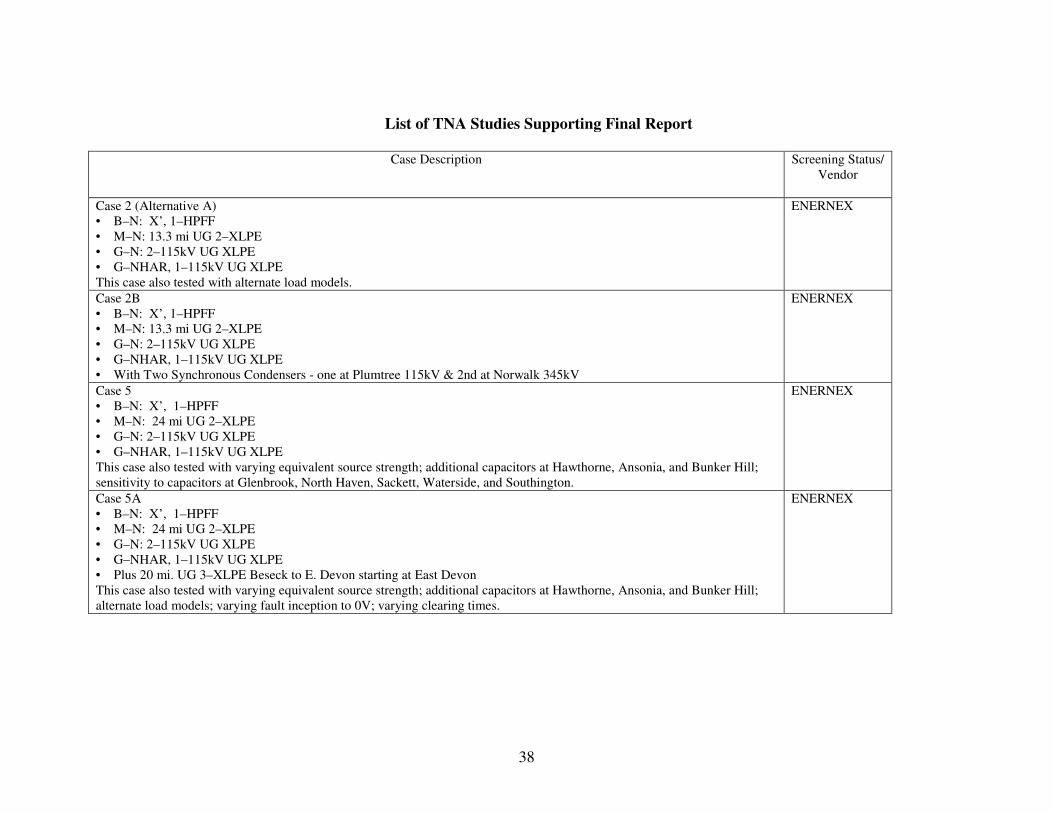
Figure 3
The Companies were interested in KEMA’s proposal to replace capacitor banks with C-
Type filters tuned to the third harmonic as a means of maximizing the underground
components. However, particularly since this is a novel concept not proven in similar
applications18, they considered that the results of frequency domain analyses of system
performance under normal conditions did not sufficiently justify the adoption of this
strategy without further analysis. Accordingly, the Companies further investigated the
potential of C-Type filters. They commissioned TNA studies that modeled system
performance under both normal and contingency conditions, assuming the replacement of
capacitor banks with C-Type filters tuned to the third harmonic, as suggested by KEMA.
These results showed that overvoltages were increased under many contingencies and
that the C-Type filters were found to be ineffective (under some system events they were
18 C-Type filters can be and are used to resolve specific frequency problems that may exist within an area, but have not been utilized as a generic solution for TOV problems.
PB Case 5 + 20 mile extra cable (50% Load)Impact of C Filters on Maximum TOV in 6 to 7 cycle Period
-0.50
-0.40
-0.30
-0.20
-0.10
0.00
0.10
0.20
0.30
0.40
0.50
0.00 5 .00 1 0.00 1 5 .00 2 0.00 2 5 .00 3 0.00 3 5 .00
Del
ta. T
OV
Performance
Performance improvement

36
helpful, but in a majority of the cases, they were harmful). The results for one of the
Cases including Type-C filters are shown in Figure 3.
The Companies and their consultants have considered why the C-Type filters do
not improve system performance under these contingency conditions. Under contingency
conditions, the SWCT 345-kV system resonance is close to the second harmonic without
the filters. Addition of the C-Type third harmonic filters does not damp this resonance
significantly, but actually tends to shift the resonance to a lower frequency. Additionally,
as shown in the KEMA study, the driving point impedance on the 345-kV system at the
third harmonic can be higher with the filters in service.
Two other items are of significant importance when evaluating the C-Type filters,
as suggested by KEMA. The first is that a significant portion of the filters are located at
Southington, Frost Bridge, and Berlin substations. When one considers system outages,
like the outage of a 345-kV line, these filters are electrically distant from the charging
associated with the 345-kV cables being considered. Of more significance is the fact that
in light load periods, very few capacitor banks (or C-Type filters) would be expected to
be in service. Yet, the GE testing has shown this system configuration to produce some
of the highest TOVs. The filters cannot be effective if they are not in service when they
are needed most. Thus, under many contingencies, overvoltages are exacerbated by the
C-Type filters, even though frequency scans for normal conditions imply a favorable
impact.
KEMA’s estimates of the incremental physical space required for converting
existing 115-kV capacitor banks to C-Type filters are that a doubling of space is required,
compared to the space required for the existing capacitor banks. The space required may

37
be greater than KEMA’s estimate when the unusual filter rating requirements for this
application are considered. In many cases, this space is not available within the
substations, and thus would require taking land from adjacent properties.
III. Next Steps
If a Certificate of Environmental Compatibility and Public Need is issued for the
Project, then the Project (once engineering design is final) will undergo review by ISO
and input from the NEPOOL Reliability Committee pursuant to Section 18.4 of the
Restated NEPOOL Agreement. While the support expressed for Cases 2 and 5 by ISO in
this report as part of the ROC Group is not a substitute for the 18.4 process and does not
guarantee approval, the ISO’s support represents a good faith belief that no
insurmountable barriers to 18.4 approval appear to exist.
38
List of TNA Studies Supporting Final Report
Case Description
Screening Status/
Vendor
Case 2 (Alternative A) • B–N: X’, 1–HPFF • M–N: 13.3 mi UG 2–XLPE • G–N: 2–115kV UG XLPE • G–NHAR, 1–115kV UG XLPE This case also tested with alternate load models.
ENERNEX
Case 2B • B–N: X’, 1–HPFF • M–N: 13.3 mi UG 2–XLPE • G–N: 2–115kV UG XLPE • G–NHAR, 1–115kV UG XLPE • With Two Synchronous Condensers - one at Plumtree 115kV & 2nd at Norwalk 345kV
ENERNEX
Case 5 • B–N: X’, 1–HPFF • M–N: 24 mi UG 2–XLPE • G–N: 2–115kV UG XLPE • G–NHAR, 1–115kV UG XLPE This case also tested with varying equivalent source strength; additional capacitors at Hawthorne, Ansonia, and Bunker Hill; sensitivity to capacitors at Glenbrook, North Haven, Sackett, Waterside, and Southington.
ENERNEX
Case 5A • B–N: X’, 1–HPFF • M–N: 24 mi UG 2–XLPE • G–N: 2–115kV UG XLPE • G–NHAR, 1–115kV UG XLPE • Plus 20 mi. UG 3–XLPE Beseck to E. Devon starting at East Devon This case also tested with varying equivalent source strength; additional capacitors at Hawthorne, Ansonia, and Bunker Hill; alternate load models; varying fault inception to 0V; varying clearing times.
ENERNEX

39
Case 5B • B–N: X’, 1–HPFF • M–N: 24 mi UG 2–XLPE • G–N: 2–115kV UG XLPE • G–NHAR, 1–115kV UG XLPE • Plus 5 mi. UG 3–XLPE Beseck to E. Devon starting at East Devon This case also tested with varying shunt reactors on East Devon to Beseck cables; varying fault inception to 0V; varying clearing times; varying equivalent source strength; additional capacitors at Hawthorne, Ansonia, and Bunker Hill; alternate load
model.
ENERNEX
Case 5C • B–N: X’, 1–HPFF • M–N: 24 mi UG 2–XLPE • G–N: 2–115kV UG XLPE • G–NHAR, 1–115kV UG XLPE • Plus 10 mi. UG 3–XLPE Beseck to E. Devon starting at East Devon This case also tested with varying equivalent source strength; additional capacitors at Hawthorne, Ansonia, and Bunker Hill; alternate load models; varying fault inception to 0V; varying clearing times.
ENERNEX
Case 5 • B–N: X’, 1–HPFF • M–N: 24 mi UG 2–XLPE • G–N: 2–115kV UG XLPE • G–NHAR, 1–115kV UG XLPE This case tested with and without C-Type filters, additional capacitors, and Norwalk Harbor 1 and Milford 1 generators in service.
PB
Case 5A • B–N: X’, 1–HPFF • M–N: 24 mi UG 2–XLPE • G–N: 2–115kV UG XLPE • G–NHAR, 1–115kV UG XLPE • Plus 20 mi. UG 3–XLPE Beseck to E. Devon starting at East Devon This case tested with and without C-Type filters.
PB
Case 5C • B–N: X’, 1–HPFF • M–N: 24 mi UG 2–XLPE • G–N: 2–115kV UG XLPE • G–NHAR, 1–115kV UG XLPE • Plus 10 mi. UG 3–XLPE Beseck to E. Devon starting at East Devon
PB

40
Case 5 • B–N: X’, 1–HPFF • M–N: 24 mi UG 2–XLPE • G–N: 2–115kV UG XLPE • G–NHAR, 1–115kV UG XLPE This case also tested varying clearing times; a synchronous condenser at Plumtree 115kV (1) and with a synchronous condenser at Plumtree 115kV and Norwalk 345kV (2).
GE
{N0725680}
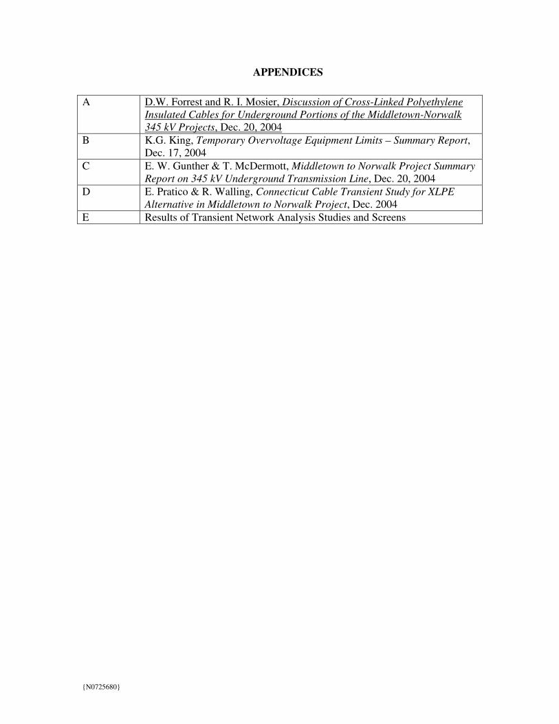
APPENDICES A D.W. Forrest and R. I. Mosier, Discussion of Cross-Linked Polyethylene
Insulated Cables for Underground Portions of the Middletown-Norwalk 345 kV Projects, Dec. 20, 2004
B K.G. King, Temporary Overvoltage Equipment Limits – Summary Report, Dec. 17, 2004
C E. W. Gunther & T. McDermott, Middletown to Norwalk Project Summary Report on 345 kV Underground Transmission Line, Dec. 20, 2004
D E. Pratico & R. Walling, Connecticut Cable Transient Study for XLPE Alternative in Middletown to Norwalk Project, Dec. 2004
E Results of Transient Network Analysis Studies and Screens
Related Documents