Release Note Release Note Release Date : June. 2014 Product Ver. : GTSNX 2014 (v2.1) Integrated Solver Optimized for the next generation 64-bit platform Finite Element Solutions for Geotechnical Engineering Enhancements 3. Post Processing 3.1 3D 2D Section (Save & Export to SoilWorks) 1. Pre Processing 1.1 Embedded Beam Element 3.2 3D PDF Report (Improvement in data summary) 3.3 Relative deformed shape for Dynamic analysis results 34I ti P b lt 1.2 Geological Parameters DB 1.3 Repair Shape (Topology Optimize) 1.4 Model Simplification (Remove small entity) 3.4 Improvement in Probe result * Appendix Creep / Shrinkage Function Group 2. Analysis 2.1 Hardening Soil (MMC Hardening) 2 2 Soft Soil Creep (Secondary Consolidation) Creep / Shrinkage Function Group 2.2 Soft Soil Creep (Secondary Consolidation) 2.3 Geometric Nonlinear Effects (Estimate Initial configuration) 2.4 Concrete Creep & Shrinkage (Time-dependent behavior) 2.5 General Contact Element (Contact Analysis) Integrated Solver Optimized for the next generation 64-bit platform Finite Element Solutions for Geotechnical Engineering

Welcome message from author
This document is posted to help you gain knowledge. Please leave a comment to let me know what you think about it! Share it to your friends and learn new things together.
Transcript
Release NoteRelease NoteRelease Date : June. 2014
Product Ver. : GTSNX 2014 (v2.1)
Integrated Solver Optimized for the next generation 64-bit platform
Finite Element Solutions for Geotechnical Engineering
Enhancements3. Post Processing
3.1 3D 2D Section (Save & Export to SoilWorks)
1. Pre Processing
1.1 Embedded Beam Element
3.2 3D PDF Report
(Improvement in data summary)
3.3 Relative deformed shape for Dynamic analysis results
3 4 I t i P b lt
1.2 Geological Parameters DB
1.3 Repair Shape (Topology Optimize)
1.4 Model Simplification (Remove small entity)
3.4 Improvement in Probe result
* Appendix
Creep / Shrinkage Function Group
2. Analysis
2.1 Hardening Soil (MMC Hardening)
2 2 Soft Soil Creep (Secondary Consolidation) Creep / Shrinkage Function Group2.2 Soft Soil Creep (Secondary Consolidation)
2.3 Geometric Nonlinear Effects
(Estimate Initial configuration)
2.4 Concrete Creep & Shrinkagep g
(Time-dependent behavior)
2.5 General Contact Element (Contact Analysis)
Integrated Solver Optimized for the next generation 64-bit platform
Finite Element Solutions for Geotechnical Engineering
GTSNX 2014 V2.1 Release NoteGTSNX 2014 Enhancement
1. Pre Processing
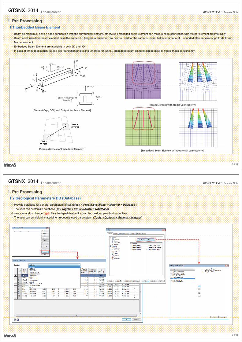
1.1 Embedded Beam Element
Beam element must have a node connection with the surrounded element, otherwise embedded beam element can make a node connection with Mother element automatically.
Beam and Embedded beam element have the same DOF(degree of freedom), so can be used for the same purpose, but even a node of Embedded element cannot protrude from
Mother element.
Embedded Beam Element are available in both 2D and 3D.
In case of embedded structures like pile foundation or pipeline umbrella for tunnel, embedded beam element can be used to model those conveniently.
ECS z−zM
ECS x−
A
B
ECS y−ECS z
xM
xxN
zQ
yM yQ
xxN
zM
zQ
A
xM
xx
yMyQ
C
DE
F
ECS z−
ECS y−
Stress recovery point (I-section)
[Beam Element with Nodal Connectivity]DE
[Element Csys, DOF, and Output for Beam Element]
[ y]
3 / 31
[Schematic view of Embedded Element] [Embedded Beam Element without Nodal connectivity]
GTSNX 2014 V2.1 Release NoteGTSNX 2014 Enhancement
1. Pre Processing
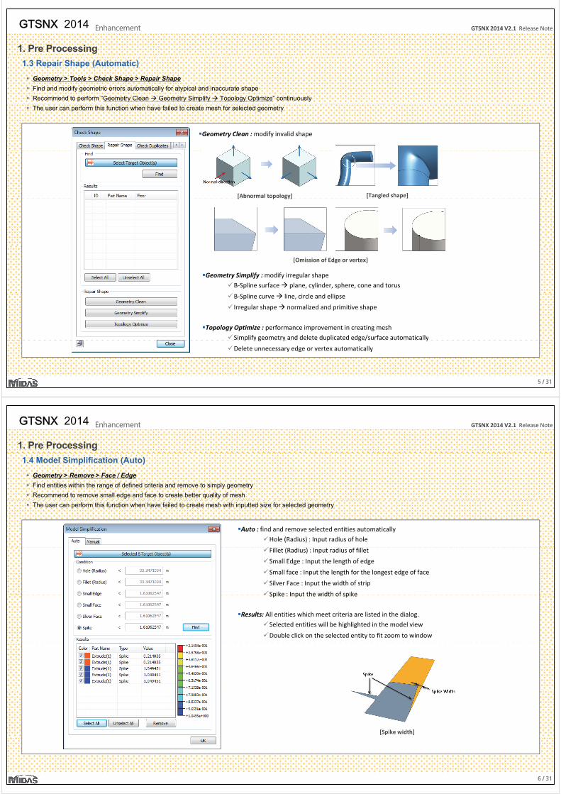
1.2 Geological Parameters DB (Database)
Provide database for general parameters of soil (Mesh > Prop./Csys./Func. > Material > Database )
The user can customize database (C:\Program Files\MIDAS\GTS NX\Dbase)
(Users can add or change *.gdb files. Notepad (text editor) can be used to open this kind of file)
The user can set default material for frequently used parameters. (Tools > Options > General > Material)
4 / 31
GTSNX 2014 V2.1 Release NoteGTSNX 2014 Enhancement
1. Pre Processing
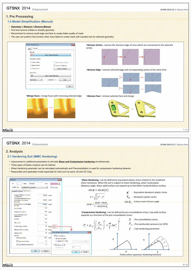
1.3 Repair Shape (Automatic)
Geometry > Tools > Check Shape > Repair Shape
Find and modify geometric errors automatically for atypical and inaccurate shape
Recommend to perform “Geometry Clean Geometry Simplify Topology Optimize” continuously
The user can perform this function when have failed to create mesh for selected geometry
Geometry Clean : modify invalid shape
[Abnormal topology] [Tangled shape][ p gy] [ g p ]
[Omission of Edge or vertex]
Geometry Simplify : modify irregular shape
B-Spline surface plane, cylinder, sphere, cone and torus
B-Spline curve line, circle and ellipse
Irregular shape normalized and primitive shape
Topology Optimize : performance improvement in creating meshSimplify geometry and delete duplicated edge/surface automatically
5 / 31
p y g y p g / y
Delete unnecessary edge or vertex automatically
GTSNX 2014 V2.1 Release NoteGTSNX 2014 Enhancement
1. Pre Processing
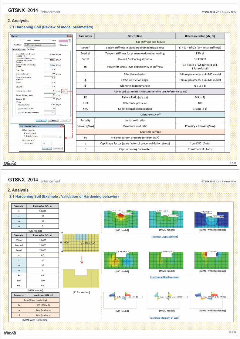
1.4 Model Simplification (Auto)
Geometry > Remove > Face / Edge
Find entities within the range of defined criteria and remove to simply geometry
Recommend to remove small edge and face to create better quality of mesh
The user can perform this function when have failed to create mesh with inputted size for selected geometry
Auto : find and remove selected entities automatically
Hole (Radius) : Input radius of hole
Fillet (Radius) : Input radius of fillet
Small Edge : Input the length of edge
Small face : Input the length for the longest edge of face
Silver Face : Input the width of strip
Spike : Input the width of spikeSpike : Input the width of spike
Results: All entities which meet criteria are listed in the dialog.
Selected entities will be highlighted in the model view
Double click on the selected entity to fit zoom to window
[Spike width]
6 / 31
GTSNX 2014 V2.1 Release NoteGTSNX 2014 Enhancement
1. Pre Processing
1.4 Model Simplification (Manual)
Geometry > Remove > Remove Manual
Find and remove entities to simplify geometry
Recommend to remove small edge and face to create better quality of mesh
The user can perform this function when have failed to create mesh with inputted size for selected geometry
Remove Vertex : remove the shortest edge of ones which are connected to the selected vertex
Remove Edge : remove selected edge and corresponding vertex at the same time
Remove Face : remove selected face and mergeMerge Faces : merge faces with removing selected edge
7 / 31
GTSNX 2014 V2.1 Release NoteGTSNX 2014 Enhancement
2. Analysis
2.1 Hardening Soil (MMC Hardening)
Improvement in additional parameters to simulate Shear and Compression hardening simultaneously
Three types of Elastic modulus can be defined
Shear hardening parameter can be calculated automatically and Preconsolidation is used for compression hardening behavior
Reasonable and applicable model especially for soils such as sand, silt and OC Clay.
Shear Hardening : can be defined by Equivalent plastic strain related to the mobilized shear resistance. When the soil is subject to shear hardening, solver recalculates dilatancy angle. Shear yield surface can expand up to the Mohr-Coulomb failure surface.dilatancy angle. Shear yield surface can expand up to the Mohr Coulomb failure surface.
2 :3
p pκ γ γ=
( )sin sinφ φ κ= κ : Equivalent deviatoric plastic strain
: Deviatoric plastic strain
: Critical state friction angle
pγ
sin sinφ φ sin φ gsin sinsin1 sin sin
cv
cv
φ φψφ φ−=
−
sin cvφ
Compression Hardening : can be defined by pre-consolidation stress. Cap yield surface expands as a function of the pre-consolidation stress
1 P1
0
m mpc
c ref vref
P mP pp
ε = + Δ Γ
: Pre-consolidation stress
: Pre-overburden pressure (or OCR)
: Cap hardening parameter
cP0cP
Γ
q q
8 / 31
p p[Yield surface expansion, Hardening behavior]
GTSNX 2014 V2.1 Release NoteGTSNX 2014 Enhancement
2. Analysis
2.1 Hardening Soil (Review of model parameters)
Parameter Description Reference value (kN, m)
Soil stiffness and failure
E50ref Secant stiffness in standard drained triaxial test Ei x (2 – Rf) /2 (Ei = Initial stiffness)
Eoedref Tangent stiffness for primary oedometer loading E50ref
Eurref Unload / reloading stiffness 3 x E50ref
0 5 ≤ ≤ 1 (0 5 f h d ilm Power for stress-level dependency of stiffness
0.5 ≤ m ≤ 1 (0.5 for hard soil, 1 for soft soil)
c Effective cohesion Failure parameter as in MC model
φ Effective friction angle Failure parameter as in MC model
ψ Ultimate dilatancy angle 0 ≤ ψ ≤ φ
Advanced parameters (Recommend to use Reference value)
Rf Failure Ratio (qf / qa) 0.9 (< 1)
Pref Reference pressure 100
KNC Ko for normal consolidation 1-sinφ (< 1)
Dilatancy cut-off
Porosity Initial void ratio -
i ( ) i id i i i ( )Porosity(Max) Maximum void ratio Porosity < Porosity(Max)
Cap yield surface
Pc Pre-overburden pressure (or from OCR) -
α Cap Shape Factor (scale factor of preconsolidation stress) from KNC (Auto)
9 / 31
β Cap Hardening Parameter from Eoedref (Auto)
GTSNX 2014 V2.1 Release NoteGTSNX 2014 Enhancement
2. Analysis
2.1 Hardening Soil (Example : Validation of Hardening behavior)
Parameter Input value (kN, m)
E 50,000
c 30
φ 36
ψ 5
[MC model] [MC model] [MMC model] [MMC with Hardening]
Parameter Input value (kN, m)
E50ref 25,000
Eoedref 25,000
Eurref 75,000
[Vertical Displacement]
γ = 20kN/m3H = 60m
m 0.5
c 30
φ 36
ψ 5 [MC model] [MMC model] [MMC with Hardening]
P t I t l (kN )
Rf 0.9
Pref 100
KNC 0.5
[MMC model]
[Horizontal Displacement]
[1st Excavation]Parameter Input value (kN, m)
Auto (Shear Hardening)
Pc 600 (OCR = 1)
α Auto (uncheck)
β A t ( h k)
[MC model] [MMC model] [MMC with Hardening]
10 / 31
β Auto (uncheck)
[MMC with Hardening][Bending Moment of wall]
GTSNX 2014 V2.1 Release NoteGTSNX 2014 Enhancement
2. Analysis( )log time
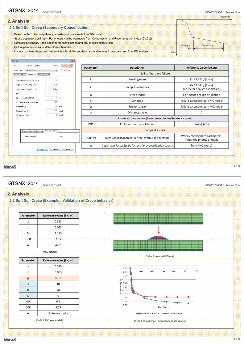
2.2 Soft Soil Creep (Secondary Consolidation)
Based on the 1D – creep theory, an extension was made to a 3D- model.
Stress-dependent stiffness ( Parameters can be estimated from Compression and Recompression index (Cc,Cs))
Consider Secondary (time-dependent) consolidation and pre-consolidation stressSecondarP i
Failure parameters as in Mohr-Coulomb model
In case that time-dependent behavior is critical, this model is applicable to estimate the creep from FE analysis. strain
SecondaryPrimary
Parameter Description Reference value (kN, m)
Soil stiffness and failure
λ Swelling index Cc / 2.303 / (1 + e)
C i i dCs / 2.303 / (1 + e)
κ Compression index/ / ( )
(Cc / 5 for a rough estimation)
μ Creep index Cc / 20 for a rough estimation
c Cohesion Failure parameter as in MC model
φ Friction angle Failure parameter as in MC modelφ Friction angle Failure parameter as in MC model
ψ Dilatancy angle 0
Advanced parameters (Recommend to use Reference value)
KNC Ko for normal consolidation 1-sinφ (< 1)
Cap yield surface
OCR / Pc Over Consolidation Ratio / Pre-overburden pressureWhen entering both parameters,
Pc has the priority of usage
α Cap Shape Factor (scale factor of preconsolidation stress) from KNC (Auto)
11 / 31
GTSNX 2014 V2.1 Release NoteGTSNX 2014 Enhancement
2. Analysis
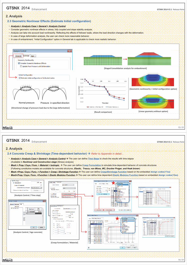
2.2 Soft Soil Creep (Example : Validation of Creep behavior)
Parameter Reference value (kN, m)
λ 0.313
κ 0.063
M 1.113
OCR 2 05
f l (k )
OCR 2.05
α Auto
[MCC model]
[Embankment with Time]
Parameter Reference value (kN, m)
λ 0.313
κ 0.063
μ 0.01
c 10
φ 28
ψ 0
KNC 0 5KNC 0.5
OCR 2.05
α Auto (uncheck)
[Soft Soil Creep model] [Result comparison : Secondary consolidation]
12 / 31
[ p ] [Result comparison : Secondary consolidation]
GTSNX 2014 V2.1 Release NoteGTSNX 2014 Enhancement
2. Analysis
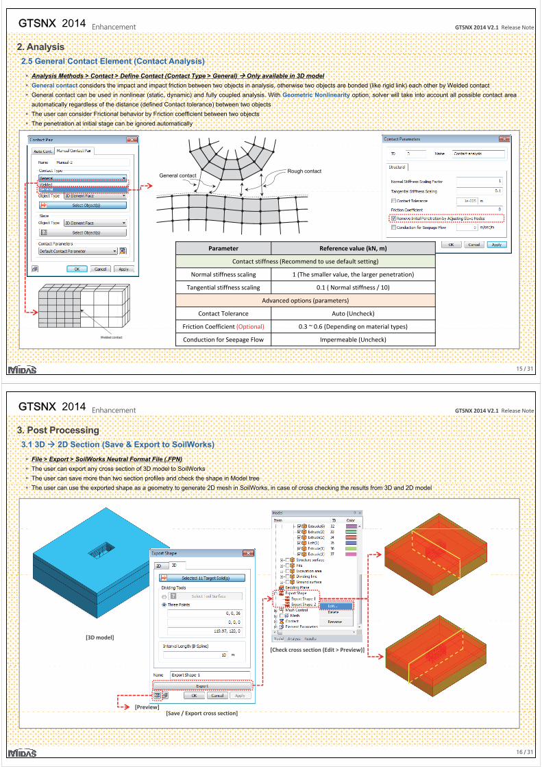
2.3 Geometric Nonlinear Effects (Estimate Initial configuration)
Analysis > Analysis Case > General > Analysis Control
Consider geometric nonlinear effects in stress, fully coupled and slope stability analysis.
Analysis can take into account load nonlinearity. Reflecting the effects of follower loads, where the load direction changes with the deformation.
In case of large deformation analysis, the user can check more reasonable behavior.
In case of embankment, “Initial Configuration” option in General tab is applicable to check more realistic behavior.
[Staged Consolidation analysis for embankment]
[Geometric nonlinearity + Initial configuration option]
Normal pressure Pressure in specified direction
[Directional change of pressure load due to the large deformation]
[Linear geometry without option][Result comparison]
13 / 31
GTSNX 2014 V2.1 Release NoteGTSNX 2014 Enhancement
2. Analysis
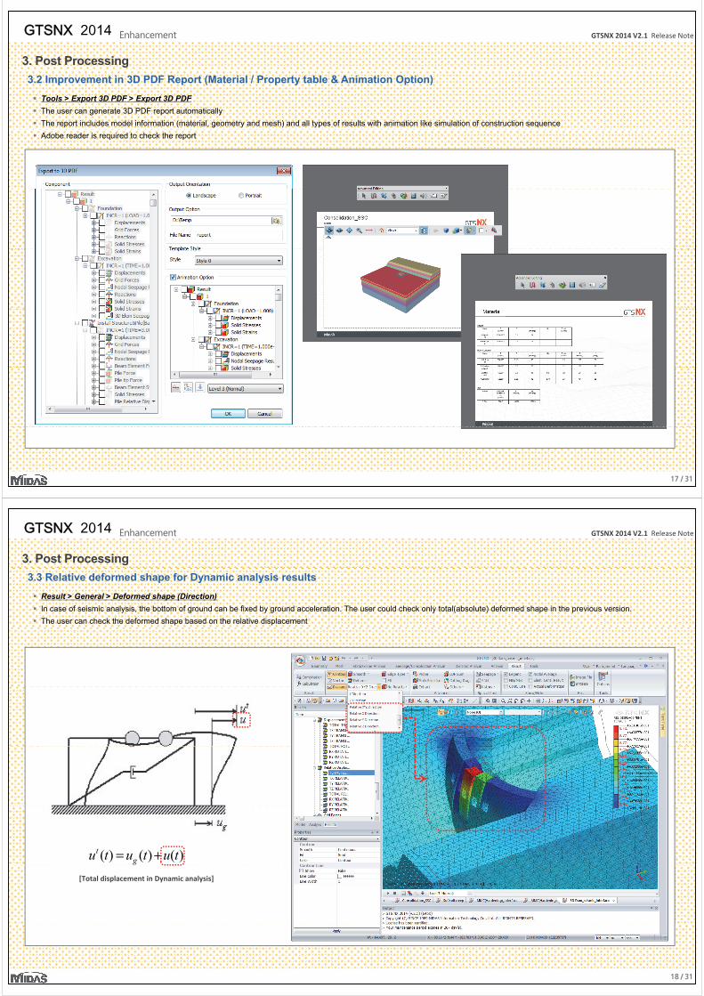
2.4 Concrete Creep & Shrinkage (Time-dependent behavior) Refer to Appendix in detail...
Analysis > Analysis Case > General > Analysis Control The user can define Time Steps to check the results with time elapse
(Available in Nonlinear and Construction stage (Stress) analysis)
Mesh > Prop./ Csys./ Func. > Material > Isotropic The user can define Creep Formulation to simulate time-dependent behavior of concrete structures
(Following constitutive models are available for concrete structures, Elastic, Tresca, von Mises, MC, Drucker Prager, and Hoek brown)
Mesh >Prop./ Csys./ Func. > Function > Creep / Shrinkage Function The user can define Creep/Shrinkage Function based on the embedded design codes(17ea)
Mesh>Prop./ Csys./ Func. >Function > Elastic Modulus Function The user can define time dependent Elastic Modulus Function based on embedded design codes(12ea)
[Analysis Control / Time step]
[Analysis Control / Age concrete]
[Creep Formulation / Material]
14 / 31
GTSNX 2014 V2.1 Release NoteGTSNX 2014 Enhancement
2. Analysis
2.5 General Contact Element (Contact Analysis)
Analysis Methods > Contact > Define Contact (Contact Type > General) Only available in 3D model
General contact considers the impact and impact friction between two objects in analysis, otherwise two objects are bonded (like rigid link) each other by Welded contact
General contact can be used in nonlinear (static, dynamic) and fully coupled analysis. With Geometric Nonlinearity option, solver will take into account all possible contact area
automatically regardless of the distance (defined Contact tolerance) between two objects
The user can consider Frictional behavior by Friction coefficient between two objects
The penetration at initial stage can be ignored automatically
Rough contactGeneral contact
Parameter Reference value (kN, m)
Contact stiffness (Recommend to use default setting)
Normal stiffness scaling 1 (The smaller value, the larger penetration)
Tangential stiffness scaling 0.1 ( Normal stiffness / 10)
Advanced options (parameters)
Contact Tolerance Auto (Uncheck)
Friction Coefficient (Optional) 0.3 ~ 0.6 (Depending on material types)
15 / 31
Welded contact
( p ) ( p g yp )
Conduction for Seepage Flow Impermeable (Uncheck)
GTSNX 2014 V2.1 Release NoteGTSNX 2014 Enhancement
3. Post Processing
3.1 3D 2D Section (Save & Export to SoilWorks)
File > Export > SoilWorks Neutral Format File (.FPN)
The user can export any cross section of 3D model to SoilWorks
The user can save more than two section profiles and check the shape in Model tree
The user can use the exported shape as a geometry to generate 2D mesh in SoilWorks, in case of cross checking the results from 3D and 2D model
[3D model]
[Check cross section (Edit > Preview)]
[S / E t ti ][Preview]
16 / 31
[Save / Export cross section]
GTSNX 2014 V2.1 Release NoteGTSNX 2014 Enhancement
3. Post Processing
3.2 Improvement in 3D PDF Report (Material / Property table & Animation Option)
Tools > Export 3D PDF > Export 3D PDF
The user can generate 3D PDF report automatically
The report includes model information (material, geometry and mesh) and all types of results with animation like simulation of construction sequence
Adobe reader is required to check the report
17 / 31
GTSNX 2014 V2.1 Release NoteGTSNX 2014 Enhancement
3. Post Processing
3.3 Relative deformed shape for Dynamic analysis results
Result > General > Deformed shape (Direction)
In case of seismic analysis, the bottom of ground can be fixed by ground acceleration. The user could check only total(absolute) deformed shape in the previous version.
The user can check the deformed shape based on the relative displacement
)()()( tututu gt +=
[Total displacement in Dynamic analysis]
18 / 31
GTSNX 2014 V2.1 Release NoteGTSNX 2014 Enhancement
3. Post Processing
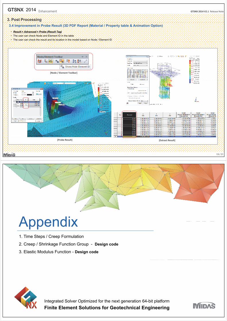
3.4 Improvement in Probe Result (3D PDF Report (Material / Property table & Animation Option)
Result > Advanced > Probe (Result Tag)
The user can check Node and Element ID in the table
The user can check the result and its location in the model based on Node / Element ID
[Node / Element Toolbar]
19 / 31
[Probe Result] [Extract Result]
AppendixAppendix1. Time Steps / Creep Formulation
2. Creep / Shrinkage Function Group - Design code
3. Elastic Modulus Function - Design code
Integrated Solver Optimized for the next generation 64-bit platform
Finite Element Solutions for Geotechnical Engineering
GTSNX 2014 V2.1 Release NoteGTSNX 2014 Enhancement
1. Time Steps / Creep Formulation
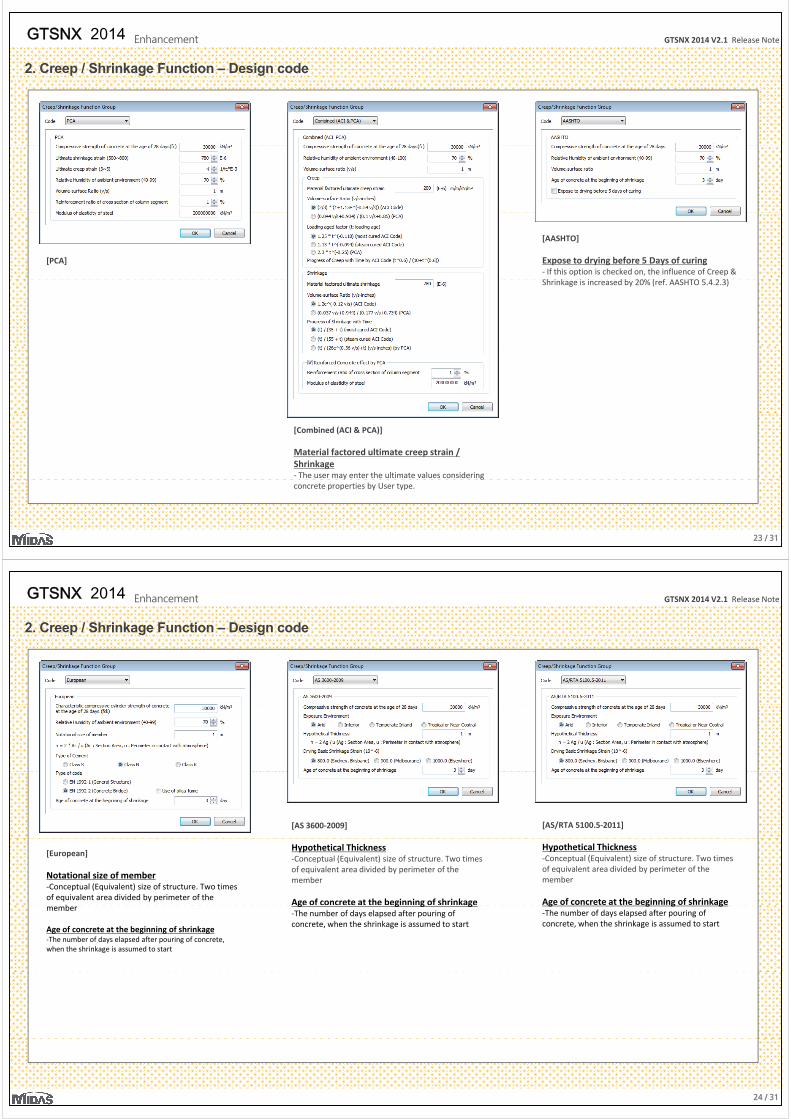
The user can define Total elapsed time and the number of increments to output results for each time step. Uniform and non-uniform time steps can be defined
In case of construction stage analysis, the user can take Age into account to consider creep/shrinkage effect generated in the previous stage. In general, the user can enter the
curing period of concrete
Two types of creep formulation are available to define Time-dependent behavior of material (Age Dependent and Age Independent)
[Age Dependent]
The stiffness of concrete changes with time, and the creep and shrinkage may cause unexpected deformation. And the creep strain of concrete d d th ti f t d th li d l d
[Analysis Control / Time step]
depends on the time of stress occurrence even under the same applied load.
GTSNX supports aging-Kelvin model and aging-Viscous model excluding the spring from Kelvin model.
·
1k 2k 3k 4k 5k
σ
[Age Independent]
k h h
1η 2η 3η 4η 5η
[Schematic view of aging-Kelvin creep model]
GTSNX can take into account the primary and secondary creep. The user can use two types of empirical law to define the creep behavior.
( )pk σ
PrimaryCreep
SecondaryCreep 1k 2k
2 or cprimarye ε 1 or c
totale ε
[Analysis Control / Age concrete]
[C F l ti / M t i l]
· · ·( )pc σ
( )sc σ
1( ) or stσ Δ
p y 1 total
[Kelvin-Maxwell creep model]
21 / 31
[Creep Formulation / Material] [Kelvin Maxwell creep model]
GTSNX 2014 V2.1 Release NoteGTSNX 2014 Enhancement
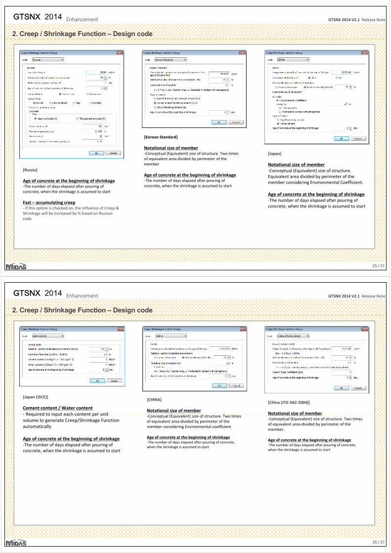
2. Creep / Shrinkage Function – Design code
[CEB-FIP(1990)] [CEB-FIP(1978)][ ( )]
Notational size of member-Conceptual (Equivalent) size of structure. Two times of equivalent area divided by perimeter of the member
[ACI]
Notational size of member-Conceptual (Equivalent) size of structure. Two times of equivalent area divided by perimeter of the member
Age of concrete at the beginning of shrinkage -The number of days elapsed after pouring of concrete, when the shrinkage is assumed to start
[ ]
Age of concrete at the beginning of shrinkage -The number of days elapsed after pouring of concrete, when the shrinkage is assumed to start
Material factored ultimate value
Age of concrete at the beginning of shrinkage -The number of days elapsed after pouring of concrete, when the shrinkage is assumed to start
- The user may enter the ultimate values considering concrete properties by ACI code or User type.
22 / 31
GTSNX 2014 V2.1 Release NoteGTSNX 2014 Enhancement
2. Creep / Shrinkage Function – Design code
[PCA]
[AASHTO]
Expose to drying before 5 Days of curing- If this option is checked on, the influence of Creep &
h k d b % ( f )Shrinkage is increased by 20% (ref. AASHTO 5.4.2.3)
[Combined (ACI & PCA)]
Material factored ultimate creep strain / Shrinkage - The user may enter the ultimate values considering
23 / 31
concrete properties by User type.
GTSNX 2014 V2.1 Release NoteGTSNX 2014 Enhancement
2. Creep / Shrinkage Function – Design code
[AS/RTA 5100.5-2011][AS 3600-2009]
Hypothetical Thickness-Conceptual (Equivalent) size of structure. Two times of equivalent area divided by perimeter of the member
Age of concrete at the beginning of shrinkage
[European]
Notational size of member-Conceptual (Equivalent) size of structure. Two times of equivalent area divided by perimeter of the
b
Hypothetical Thickness-Conceptual (Equivalent) size of structure. Two times of equivalent area divided by perimeter of the member
Age of concrete at the beginning of shrinkage g g g g-The number of days elapsed after pouring of concrete, when the shrinkage is assumed to start
member
Age of concrete at the beginning of shrinkage -The number of days elapsed after pouring of concrete, when the shrinkage is assumed to start
g g g g-The number of days elapsed after pouring of concrete, when the shrinkage is assumed to start
24 / 31
GTSNX 2014 V2.1 Release NoteGTSNX 2014 Enhancement
2. Creep / Shrinkage Function – Design code
[Korean Standard]
[Japan]
Notational size of member-Conceptual (Equivalent) size of structure
[Korean Standard]
Notational size of member-Conceptual (Equivalent) size of structure. Two times of equivalent area divided by perimeter of the member
[Russia] -Conceptual (Equivalent) size of structure. Equivalent area divided by perimeter of the member considering Environmental Coefficient.
Age of concrete at the beginning of shrinkage -The number of days elapsed after pouring of
Age of concrete at the beginning of shrinkage -The number of days elapsed after pouring of concrete, when the shrinkage is assumed to start
[Russia]
Age of concrete at the beginning of shrinkage -The number of days elapsed after pouring of concrete, when the shrinkage is assumed to start
Fast – accumulating creepconcrete, when the shrinkage is assumed to start
g p- If this option is checked on, the influence of Creep & Shrinkage will be increased by % based on Russian code
25 / 31
GTSNX 2014 V2.1 Release NoteGTSNX 2014 Enhancement
2. Creep / Shrinkage Function – Design code
[Japan (JSCE)]
Cement content / Water content- Required to input each content per unit
[CHINA]
Notational size of member
[China (JTG D62-2004)]
Notational size of member- Required to input each content per unit volume to generate Creep/Shrinkage Function automatically
Age of concrete at the beginning of shrinkage -The number of days elapsed after pouring of
-Conceptual (Equivalent) size of structure. Two times of equivalent area divided by perimeter of the member considering Environmental coefficient
Age of concrete at the beginning of shrinkage -The number of days elapsed after pouring of concrete, when the shrinkage is assumed to start
Notational size of member-Conceptual (Equivalent) size of structure. Two times of equivalent area divided by perimeter of the member.
Age of concrete at the beginning of shrinkage -The number of days elapsed after pouring of concrete,
concrete, when the shrinkage is assumed to startwhen the shrinkage is assumed to start
when the shrinkage is assumed to start
26 / 31
GTSNX 2014 V2.1 Release NoteGTSNX 2014 Enhancement
2. Creep / Shrinkage Function – Design code
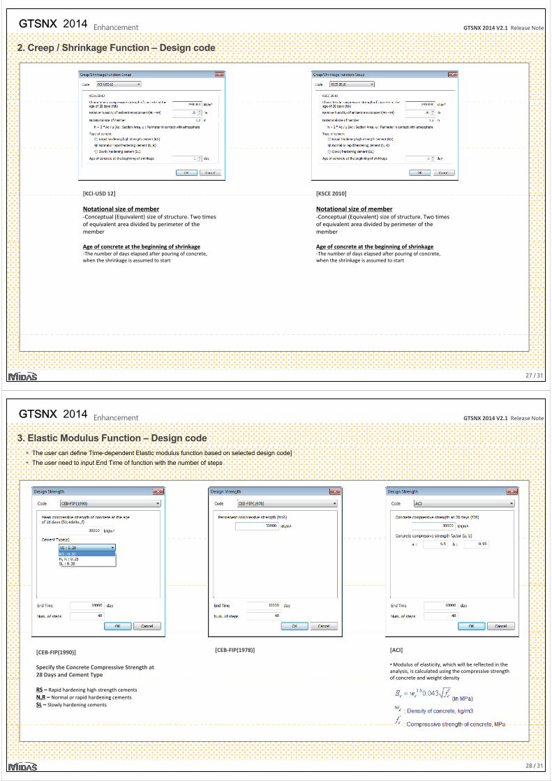
[KCI-USD 12] [KSCE 2010][KCI USD 12]
Notational size of member-Conceptual (Equivalent) size of structure. Two times of equivalent area divided by perimeter of the member
[KSCE 2010]
Notational size of member-Conceptual (Equivalent) size of structure. Two times of equivalent area divided by perimeter of the member
Age of concrete at the beginning of shrinkage -The number of days elapsed after pouring of concrete, when the shrinkage is assumed to start
Age of concrete at the beginning of shrinkage -The number of days elapsed after pouring of concrete, when the shrinkage is assumed to start
27 / 31
GTSNX 2014 V2.1 Release NoteGTSNX 2014 Enhancement
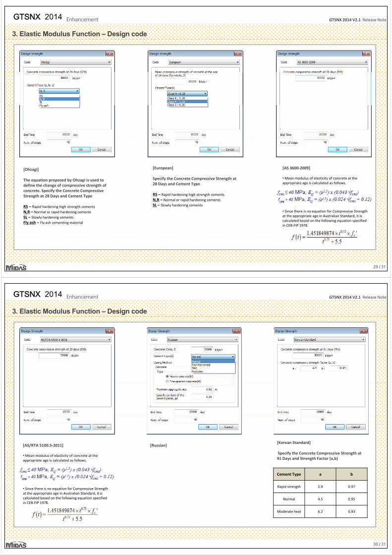
3. Elastic Modulus Function – Design code
The user can define Time-dependent Elastic modulus function based on selected design code]
The user need to input End Time of function with the number of steps
[CEB-FIP(1990)]
Specify the Concrete Compressive Strength at 28 Days and Cement Type
[CEB-FIP(1978)] [ACI]
• Modulus of elasticity, which will be reflected in the analysis, is calculated using the compressive strength of concrete and weight density
RS – Rapid hardening high strength cementsN,R – Normal or rapid hardening cementsSL – Slowly hardening cements
of concrete and weight density
28 / 31
GTSNX 2014 V2.1 Release NoteGTSNX 2014 Enhancement
3. Elastic Modulus Function – Design code
[Ohzagi] [European] [AS 3600-2009]
The equation proposed by Ohzagi is used to define the change of compressive strength of concrete. Specify the Concrete Compressive Strength at 28 Days and Cement Type
Specify the Concrete Compressive Strength at 28 Days and Cement Type
RS – Rapid hardening high strength cementsN,R – Normal or rapid hardening cementsSL Slowly hardening cements
• Mean modulus of elasticity of concrete at the appropriate age is calculated as follows.
RS – Rapid hardening high strength cementsN,R – Normal or rapid hardening cementsSL – Slowly hardening cementsFly ash – Fly ash cementing material
SL – Slowly hardening cements
• Since there is no equation for Compressive Strength at the appropriate age in Australian Standard, it is calculated based on the following equation specified in CEB-FIP 1978.
29 / 31
GTSNX 2014 V2.1 Release NoteGTSNX 2014 Enhancement
3. Elastic Modulus Function – Design code
[AS/RTA 5100.5-2011] [Russian][Korean Standard]
• Mean modulus of elasticity of concrete at the appropriate age is calculated as follows.
Specify the Concrete Compressive Strength at 91 Days and Strength Factor (a,b)
Cement Type a b
• Since there is no equation for Compressive Strength at the appropriate age in Australian Standard, it is calculated based on the following equation specified in CEB-FIP 1978.
Rapid strength 2.9 0.97
Normal 4.5 0.95
Moderate heat 6.2 0.93
30 / 31
GTSNX 2014 V2.1 Release NoteGTSNX 2014 Enhancement
3. Elastic Modulus Function – Design code
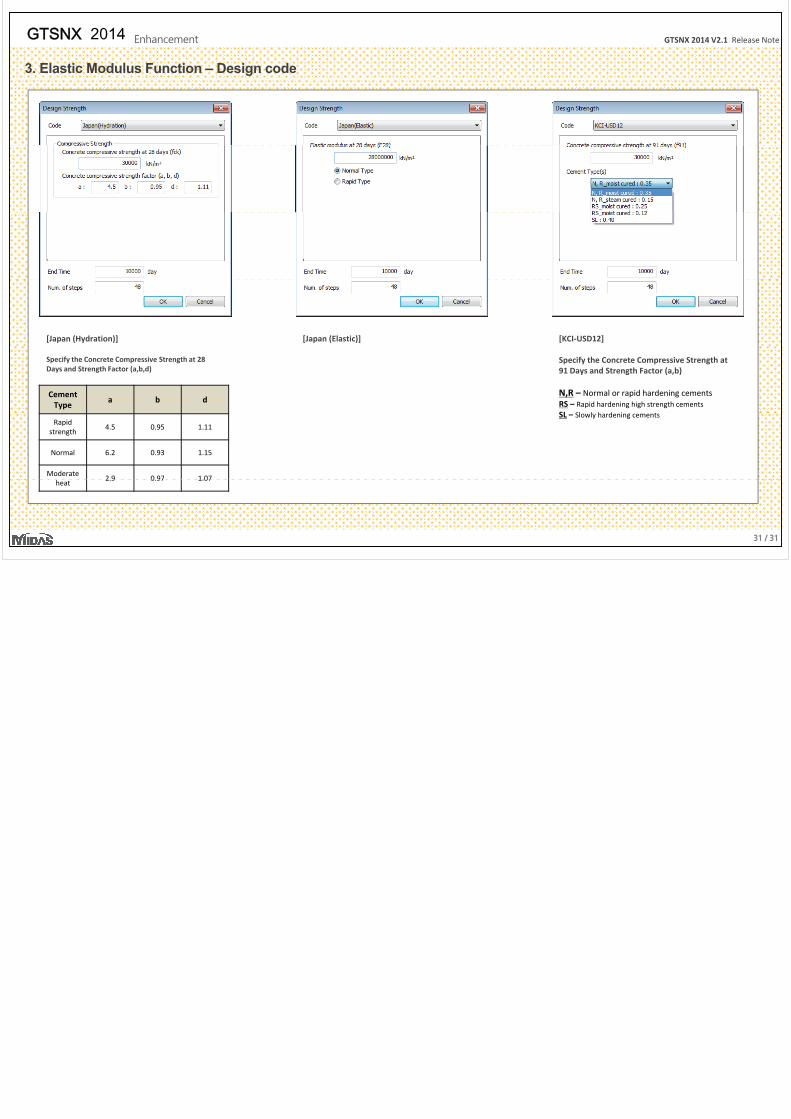
[Japan (Hydration)] [Japan (Elastic)] [KCI-USD12]
Specify the Concrete Compressive Strength at 28 Days and Strength Factor (a,b,d)
CementType
a b d
Specify the Concrete Compressive Strength at 91 Days and Strength Factor (a,b)
N,R – Normal or rapid hardening cementsRS – Rapid hardening high strength cementsSL Sl l h d i t
Rapid strength
4.5 0.95 1.11
Normal 6.2 0.93 1.15
Moderate 2 9 0 97 1 07
SL – Slowly hardening cements
31 / 31
heat2.9 0.97 1.07
Related Documents