Fwa,Anupam&Ong RELATIVE EFFECTIVENESS OF GROOVES IN TIRE AND PAVEMENT IN REDUCING VEHICLE HYDROPLANING RISK T. F. Fwa 1 , Kumar Anupam 2 and G. P. Ong 3 1 Professor, 2 Graduate Research Assistant Department of Civil Engineering National University of Singapore 10 Kent Ridge Crescent Republic of Singapore, 119260 3 Postdoctoral Research Associate School of Civil Engineering Purdue University Civil Engineering Building 550 Stadium Mall Drive West Lafayette, IN, 47907-2051 Total Number of Words Number of words in text: = 4304 words equivalent Number of tables: 5 (5*250) = 1250 words equivalent Number of figures: 5 (5*250) = 1250 words equivalent ------------------------------------- ------------------------------- Total number of words = 6804 words equivalent Corresponding author: Professor T.F. Fwa Dept of Civil Engineering National University of Singapore 10 Kent Ridge Crescent Republic of Singapore, 119260 E-mail: [email protected] Fax: 65-6779-1635 Revised November 2009 TRB 2010 Annual Meeting CD-ROM Paper revised from original submittal.

Welcome message from author
This document is posted to help you gain knowledge. Please leave a comment to let me know what you think about it! Share it to your friends and learn new things together.
Transcript

Fwa,Anupam&Ong
RELATIVE EFFECTIVENESS OF GROOVES IN TIRE AND PAVEMENT IN REDUCING VEHICLE HYDROPLANING RISK
T. F. Fwa1, Kumar Anupam2 and G. P. Ong3
1 Professor, 2 Graduate Research Assistant Department of Civil Engineering National University of Singapore
10 Kent Ridge Crescent Republic of Singapore, 119260
3 Postdoctoral Research Associate School of Civil Engineering
Purdue University Civil Engineering Building
550 Stadium Mall Drive West Lafayette, IN, 47907-2051
Total Number of Words
Number of words in text: = 4304 words equivalent Number of tables: 5 (5*250) = 1250 words equivalent Number of figures: 5 (5*250) = 1250 words equivalent ------------------------------------- ------------------------------- Total number of words = 6804 words equivalent Corresponding author: Professor T.F. Fwa
Dept of Civil Engineering National University of Singapore 10 Kent Ridge Crescent Republic of Singapore, 119260 E-mail: [email protected] Fax: 65-6779-1635
Revised November 2009
TRB 2010 Annual Meeting CD-ROM Paper revised from original submittal.

Fwa,Anupam&Ong 1
RELATIVE EFFECTIVENESS OF GROOVES IN TIRE AND PAVEMENT
IN REDUCING VEHICLE HYDROPLANING RISK
by
T. F. Fwa, Kumar Anupam and G. P. Ong
ABSTRACT
Grooving of pavement surface and tire tread has been accepted as a good practice to enhance road travel safety against wet-weather skidding and hydroplaning. There have been many guidelines on their use in practice, basically derived from findings of experimental studies and field experience. There is a lack of theoretical studies to provide insights into the factors and mechanisms involved. This paper presents an attempt to apply a theoretically derived analytical simulation model to study the relative effectiveness of pavement grooving and tire grooving in reducing vehicle hydroplaning risk. Three basic grooving configurations were considered: ungrooved, longitudinally grooved, and transversely grooved. Altogether there are nine different combinations of grooving configurations. To form a common basis for comparison, constant values of groove width, groove spacing and water film thickness were considered in the computation of hydroplaning speeds for different groove depths. Overall, the analysis shows that transverse grooves perform better than longitudinal grooves in raising hydroplaning speed (i.e. reducing hydroplaning risk), and that pavement grooving is a more effective measure than grooving tire tread in reducing hydroplaning risk. Further detailed examinations of the results were conducted to study the practical implications of the findings. It was found that for longitudinal grooving which is commonly adopted in highways, pavement and tire grooving are of equal importance in their contributions towards reducing hydroplaning risk. In the case of runways where transverse grooving is the standard practice, pavement grooving is the dominating component in guarding against hydroplaning.
TRB 2010 Annual Meeting CD-ROM Paper revised from original submittal.

Fwa,Anupam&Ong 2
RELATIVE EFFECTIVENESS OF GROOVES IN TIRE AND PAVEMENT IN REDUCING VEHICLE HYDROPLANING RISK
INTRODUCTION
Statistics from various parts of the world indicate that approximately 20% of all road traffic accidents occur in wet weather conditions (1-3). Although there are no detailed statistics on the exact causes of the wet-weather accidents, it is believed that low skid resistance and hydroplaning are major factors leading to the accidents (1-2, 4). Hydroplaning refers to a situation in which the presence of water film in the tire-and-pavement contact region significantly reduces the frictional resistance at the interface, and results in the loss of skid resistance and vehicle steering control.
On a road surface with a known thickness of water film, the factors that influence vehicle hydroplaning speed (i.e. vehicle speed at which hydroplaning occurs) include tire related factors and pavement related factors. The main tire related factors are tire inflation pressure, wheel load, tread depth and tire type. For instance, increasing tire inflation pressure, wheel load or tire tread depth will raise the hydroplaning speed, hence reducing hydroplaning risk (5-8). The main pavement related factors that affect hydroplaning speed are surface microtexture, macrotexture, and pavement cross-slope. Increasing pavement cross-slope facilitates drainage, resulting in thinner water film thickness on the pavement surface and higher hydroplaning speed (9). Pavement macrotexture including pavement grooving) is known to be another factor (10) that has a major impact on hydroplaning speed. All other factors being equal, deeper mean texture depths or pavement grooves help to raise hydroplaning speed (11).
In normal highway operations, common measures that are available to highway authorities for the purpose of reducing the risk of hydroplaning can be broadly grouped under two main categories: traffic operation control measures and pavement management measures. Traffic operation control measures include speed control measures, and enforcement of legal minimum tire tread groove depth. The common pavement management measures are pavement grooving and pavement resurfacing to improve surface macrotexture. It is of interest to highway engineers and agencies to know the relative effectiveness of different measures in reducing the hydroplaning risk of vehicles on the highway. In this paper, the relative effectiveness of two measures, namely grooving of pavement surface and maintaining sufficient groove depth in tire tread, is studied. For this comparative study, identical groove patterns are considered for both pavement surface and tire tread. To facilitate the analysis, two basic forms of groove patterns, longitudinal grooves and transverse grooves, are examined for a standard ASTM automobile tire. The case of smooth tire sliding on a smooth pavement surface is taken as the basis of reference to evaluate the benefits of introducing tire or pavement grooves.
METHOD OF ANALYSIS Analytical Model Adopted
A numerical 3-dimensional finite-element hydroplaning simulation model developed by the authors earlier (12) is adopted to evaluate the hydroplaning speed of a vehicle. The
TRB 2010 Annual Meeting CD-ROM Paper revised from original submittal.

Fwa,Anupam&Ong 3
model simulates hydroplaning of a vehicle with locked wheels sliding on a wet (or flooded) pavement surface. It is a theoretical model derived from hydrodynamics theory and solid mechanics principles. The vehicle hydroplaning problem is solved as a coupled fluid-structure-interaction problem with contact modeling.
Figure 1 shows the finite element hydroplaning simulation model. There are three main components of the model, namely the pneumatic tire sub-model, the pavement surface sub-model, and the fluid sub-model. The solution procedure involves an iterative process dealing with solving interactions between these models, i.e. tire-pavement contact modeling, fluid-tire-interaction, and fluid-pavement interaction. Hydroplaning is defined to have occurred when the total hydrodynamic uplift force becomes equal to the tire load. The final converged solution would yield the following results: tire deformation profile, fluid drag and uplift forces, tire-pavement normal reaction and traction forces. Details of the theoretical formulation of the simulation model can be found in the reference (12).
The input data necessary for the simulation analysis using the model are: • Tire dimensions – tire radius and width • Tire inflation pressure • Tire elastic properties – modulus of elasticity and Poisson’s ratio of each of the
following three components: tire rim, tire sidewalls, and tire tread • Wheel load – magnitude of applied wheel load • Physical properties of water – temperature, density, dynamic viscosity,
kinematic viscosity • Water film thickness on pavement surface
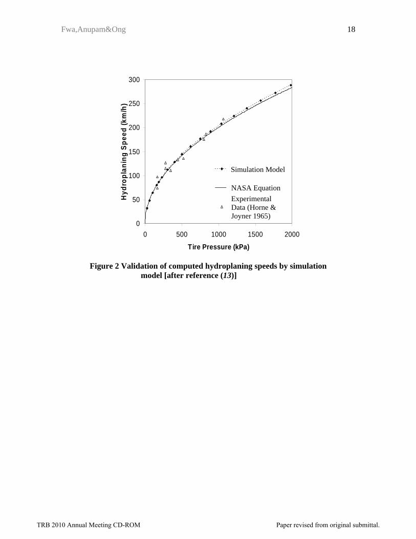
Validation of Model
The validation of the hydroplaning speed simulation model has been performed by the authors against past experimental data on hydroplaning on smooth pavement surfaces (13-14) and on grooved pavement surfaces (15). An example of validation is shown in Figure 2 in which computer simulation results of hydroplaning speeds of a smooth tire sliding on a smooth pavement surface are plotted against recorded data from experiments conducted by NASA on aircraft braking (6). The authors have also validated the applicability of the simulation model for analyzing hydroplaning speeds of vehicles with rib tires (14).
Scope of Analysis
The aim of this study is to evaluate the relative effectiveness of two grooving measures, namely grooving of pavement surface and maintaining sufficient groove depth in tire tread, in reducing the hydroplaning risk of automobiles. The relative vehicular hydroplaning risks of two pavement sections can be assessed by computing their respective hydroplaning speeds. The pavement section that has a lower vehicular hydroplaning risk is the one with the higher hydroplaning speed. The relative effectiveness of the two measures in reducing hydroplaning risk can thus be assessed by comparing their respective hydroplaning speeds.
For easy interpretation in the current comparative study, identical groove patterns are considered for both pavement surface and tire tread. To facilitate the analysis, two basic
TRB 2010 Annual Meeting CD-ROM Paper revised from original submittal.
Fwa,Anupam&Ong 4
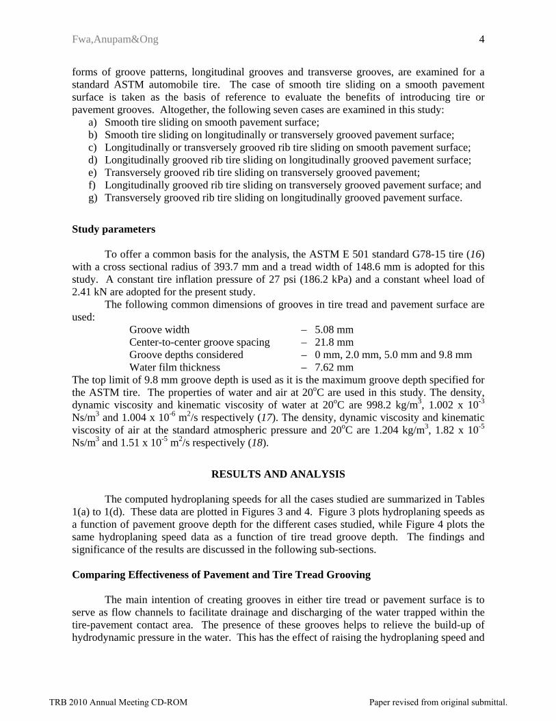
forms of groove patterns, longitudinal grooves and transverse grooves, are examined for a standard ASTM automobile tire. The case of smooth tire sliding on a smooth pavement surface is taken as the basis of reference to evaluate the benefits of introducing tire or pavement grooves. Altogether, the following seven cases are examined in this study:
a) Smooth tire sliding on smooth pavement surface; b) Smooth tire sliding on longitudinally or transversely grooved pavement surface; c) Longitudinally or transversely grooved rib tire sliding on smooth pavement surface; d) Longitudinally grooved rib tire sliding on longitudinally grooved pavement surface; e) Transversely grooved rib tire sliding on transversely grooved pavement; f) Longitudinally grooved rib tire sliding on transversely grooved pavement surface; and g) Transversely grooved rib tire sliding on longitudinally grooved pavement surface.
Study parameters
To offer a common basis for the analysis, the ASTM E 501 standard G78-15 tire (16) with a cross sectional radius of 393.7 mm and a tread width of 148.6 mm is adopted for this study. A constant tire inflation pressure of 27 psi (186.2 kPa) and a constant wheel load of 2.41 kN are adopted for the present study.
The following common dimensions of grooves in tire tread and pavement surface are used:
Groove width – 5.08 mm Center-to-center groove spacing – 21.8 mm Groove depths considered – 0 mm, 2.0 mm, 5.0 mm and 9.8 mm Water film thickness – 7.62 mm
The top limit of 9.8 mm groove depth is used as it is the maximum groove depth specified for the ASTM tire. The properties of water and air at 20oC are used in this study. The density, dynamic viscosity and kinematic viscosity of water at 20oC are 998.2 kg/m3, 1.002 x 10⁻³ Ns/m3 and 1.004 x 10⁻⁶ m2/s respectively (17). The density, dynamic viscosity and kinematic viscosity of air at the standard atmospheric pressure and 20oC are 1.204 kg/m3, 1.82 x 10⁻⁵ Ns/m3 and 1.51 x 10⁻⁵ m2/s respectively (18).
RESULTS AND ANALYSIS
The computed hydroplaning speeds for all the cases studied are summarized in Tables 1(a) to 1(d). These data are plotted in Figures 3 and 4. Figure 3 plots hydroplaning speeds as a function of pavement groove depth for the different cases studied, while Figure 4 plots the same hydroplaning speed data as a function of tire tread groove depth. The findings and significance of the results are discussed in the following sub-sections.
Comparing Effectiveness of Pavement and Tire Tread Grooving
The main intention of creating grooves in either tire tread or pavement surface is to serve as flow channels to facilitate drainage and discharging of the water trapped within the tire-pavement contact area. The presence of these grooves helps to relieve the build-up of hydrodynamic pressure in the water. This has the effect of raising the hydroplaning speed and
TRB 2010 Annual Meeting CD-ROM Paper revised from original submittal.

Fwa,Anupam&Ong 5
reducing hydroplaning risk. This effect is clearly depicted in the upward trends of the curves plotted in Figures 3 and 4. For the purpose of evaluating the relative effectiveness of pavement and tire tread grooving in reducing hydroplaning risk, the rates of increase of hydroplaning speed with pavement groove depth given by Figure 3 can be compared with the corresponding rates of hydroplaning speed increase with tire groove depth obtained from Figure 4.
In Table 2, the average rates of hydroplaning speed increase per unit pavement groove depth are shown with the corresponding average rates of hydroplaning speed increase per unit tire groove depth. The rates for Conditions A1 and A4 refer to the sole beneficial effects of introducing longitudinal and transverse pavement grooves, respectively. They are computed as the average hydroplaning speed increase per mm groove depth for the range of pavement groove depths up to 9.8 mm. The rates for Conditions B1 and B4 are computed in a similar manner, and they represent the sole beneficial effects of introducing longitudinal and transverse tire tread grooves, respectively. Conditions A2, A3, A5 and A6 give the average rates of hydroplaning speed increase for the three top curves in Figure 3(a), 3(c), 3(d) and 3(b) respectively. They represent the beneficial effects of increasing pavement groove depth under the condition of constant tire groove depth. Similarly, Conditions B2, B3, B5 and B6 give the average rates of hydroplaning speed increase for the three top curves in Figure 4(a), 4(c), 4(d) and 4(b) respectively, and they represent the beneficial effects of increasing tire tread groove depth under the condition of constant pavement groove depth.
The following observations can be made from the computed rates in Table 2:
(1) Pavement grooving is more effective than tire tread grooving in reducing hydroplaning risk. A higher value of the computed rate in Table 2 means that the hydroplaning speed will be raised by a larger value for each mm increase in groove depth. In other word, a higher rate means a better ability in reducing hydroplaning risk. Comparison of the rate for Condition A1 with that for Condition B1, and the rate for Condition A4 with that for B4, offers the most direct assessment of the relative effectiveness of the forms of grooving in reducing hydroplaning risk. The results show that while the longitudinal pavement grooving is only marginally more effective than longitudinal tire tread grooving (1.93 versus 1.68 km/h per mm groove depth), transverse pavement grooving is substantially superior to tire tread grooving in reducing hydroplaning risk (12.86 versus 4.39 km/h per mm groove depth). One likely reason for the difference is in the magnitude of cross-sectional area available for flow discharge at the boundary of the tire-pavement contact area. The cross-sectional flow area for the case of tire grooving is equal to that of the surface water. For the case of pavement grooving, it is equal to the cross-sectional area of the surface water plus the cross-sectional areas of the pavement grooves. This difference in cross-sectional flow area is more substantial for transverse grooving because there are more number of transverse grooves than longitudinal grooves due to the oblong shape of the tire-pavement contact area.
(2) Increasing groove depth gives additive incremental benefits to existing condition. Figure 3 shows that increasing pavement groove depth will raise the hydroplaning speed, regardless of the existing pavement and tire tread condition. This is supported by the computed rates in Table 2 that the rates of Conditions A1, A2 and A3 for longitudinal pavement grooves are of similar order of magnitude, and those rates of Conditions A4, A5 and A6 for transverse pavement grooves are
TRB 2010 Annual Meeting CD-ROM Paper revised from original submittal.

Fwa,Anupam&Ong 6
similar in magnitude. The same observation and comments can be made for the results of Conditions B1, B2 and B3, and the results of Conditions B4, B5 and B6 for tire tread grooving. These described observations can be roughly detected by examining Figures 3 and 4 that the series of curves in each sub-plot of the two figures are more or less parallel.
(3) Transverse grooving is more effective than longitudinal grooving. The computed rates in Table 2 indicate that transverse grooving is more effective than longitudinal grooving in raising hydroplaning speed (i.e. reducing hydroplaning risk). This can be seen by comparing the rates of Condition A4, A5 and A6 with those of Conditions A1, A2 and A3; and comparing the rates of Condition B4, B5 and B6 with those of Conditions B1, B2 and B3. The following three reasons are the likely causes to this difference: (i) Transverse grooves have shorter drainage paths than longitudinal grooves; (ii) Because of the usual oblong shape of tire-pavement contact area, the number of drainage paths is higher in the case of transversely grooved surface; (iii) Both ends of a transverse groove are equally effective in discharging water, but this is not the case for longitudinal grooves. The upstream end of a longitudinal groove receives incoming flow, and it will not be as effective in relieving hydrodynamic pressure as the downstream end that discharges water.
Relative Effectiveness of Grooving Measures Overall, as shown in Table 3, there are nine possible combinations of grooving
configurations. The relative effectiveness of these nine different grooving configurations in reducing hydroplaning risk can be assessed by examining the magnitudes of the hydroplaning speeds calculated. Table 3 arranges the nine grooving configurations in ascending order of their hydroplaning speeds. The hydroplaning speeds listed for grooved pavement or tire are those computed for the groove depth of 9.8 mm. The order of ranking remains unchanged if any other groove depth is used. This ranking is also the ranking of hydroplaning risk. The lower the hydroplaning speed of a pavement section, the higher is the risk of vehicle hydroplaning. Hence, according to the ranking of Table 3, the case of vehicles with smooth tires traveling on a smooth pavement surface (i.e. Case C1) has the highest hydroplaning risk; and the case of vehicles with transversely grooved tires traveling on transversely grooved pavement surface (i.e. Case C9) has the lowest hydroplaning risk.
According to the magnitudes of their hydroplaning speeds, the nine grooving configurations can be divided into 4 sub-groups as shown in Table 4. Sub-groups I, II, III and IV are designated in the order of increasing effectiveness of their ability to reduce hydroplaning risk. The following observations can be made:
• Sub-group I -- This group has the lowest hydroplaning speed (i.e. with the highest hydroplaning risk) is the baseline case of smooth tire sliding on smooth pavement surface.
• Sub-group II -- With the use of longitudinal grooves in either pavement or tire tread, this group achieves an increase of about 20 to 30% in hydroplaning speed over the baseline case.
TRB 2010 Annual Meeting CD-ROM Paper revised from original submittal.

Fwa,Anupam&Ong 7
• Sub-group III – The performance of this group indicates that better results of about 50 to 80% increase in hydroplaning speed can be achieved if transverse tire tread grooves are used.
• Sub-group IV -- The best results are obtained in this group with the use of transverse pavement grooves, where a total increase of about 150 to 180% over the baseline case can be obtained.
The relative effectiveness ranking identified in Table 4 is consistent with the assessment made earlier based on the analysis of the rates of hydroplaning speed rise per unit groove depth (see Table 2 and corresponding discussion). The following are the two main common findings: (i) Both longitudinal and transverse grooves, in either tire tread or pavement surface, help to reduce hydroplaning risk; but transverse grooves are more effective than longitudinal grooves. (ii) Pavement grooves are more effective than tire tread grooves in reducing hydroplaning risk.
The likely reasons that lead to the above-described differences under the two findings have been given earlier. For the differences between the performances of tire tread and pavement grooves, a further explanation can be given by analyzing their different capacities in discharging water. A simplified analysis is illustrated in Figure 5. The tire-pavement contact area is assumed to be circular and a hydraulic head difference of 1 mm (i.e. difference between H1 and H2 in Figure 5) is considered. The computed results presented in Table 5 show that, with identical groove dimensions, pavement grooves have higher water discharge capacity than tire tread grooves. Although this analysis is too simplistic to represent the actual flow conditions, it does help to explain the different hydroplaning risk reduction effectiveness of tire and pavement grooves.
Comments on Use of Grooving for Reducing of Hydroplaning Risk The analysis presented in this study offer some insight into vehicular hydroplaning
performance when grooved tires and grooved pavements are involved. The results of the analysis enable one to make some comments related to the use of tire or pavement grooving for the purpose of reducing vehicular hydroplaning risk. Comments can be made in the following three aspects:
(1) Choice of tire tread grooving pattern. Most tread grooving patterns of car tires are basically dominated by longitudinal grooves with some secondary transverse or inclined grooves. It appears to contradict the finding of this study that transverse grooving is a more effective form of tire tread pattern for hydroplaning risk control. However, it should be noted that when it comes to negotiating horizontal curves, the hydroplaning prevention effectiveness of longitudinal and transverse grooves become reverse. Longitudinal grooves would be more effective in meeting the demand for skid resistance and hydroplaning prevention during cornering movements. There are also other considerations that are important in the choice of tire tread grooving pattern, such as wear and tear, durability and noise. Ge et al. (19) and Tetsuo et al. (20) mentioned that transverse grooves are rarely used in practice because of tire noise problems.
(2) Choice of pavement grooving pattern. Longitudinal grooves are usually used in highways if pavement grooving is adopted as the skid resistance enhancement and
TRB 2010 Annual Meeting CD-ROM Paper revised from original submittal.

Fwa,Anupam&Ong 8
hydroplaning prevention measure. On the other hand, transverse grooving is commonly employed for runway pavements. Besides being easier to construct and maintain, longitudinal grooves also have the important role in providing the needed skidding and hydroplaning resistance during cornering maneuvers. It is noted that the hydroplaning speeds achievable with the use of longitudinal grooves are normally sufficient for highway operations. In contrast, the much higher landing speeds of aircraft make transverse grooves a logical choice for runway grooving (21).
(3) Choice of measures to reduce hydroplaning risk. The results of this study present a clear message that grooving in either tire or pavement is effective in reducing vehicular hydroplaning risk. When longitudinal grooving is the measure to be adopted, as is normally the case for highway pavements, pavement grooving and tire tread grooving are about equally effective (although there is a very slight advantage in favor of pavement grooving). This means that pavement grooving by the responsible road agency is as important as the conscious action of vehicle owners to maintain a good tire tread depth. However, if transverse grooving is to be used (as is the case for airport runways), then pavement grooving is clearly the preferred measure as it is far more effective than tire tread grooving in reducing hydroplaning risk.
CONCLUSION
This paper has presented a study to analyze the relative effectiveness of grooved tire tread and grooved pavement surface in reducing hydroplaning risk. Three basic grooving configurations were considered for the tire and pavement respectively: ungrooved, longitudinally grooved, and transversely grooved. This gives rise to nine different combinations of grooving configurations. An analytical 3-dimensional finite element model was adopted for the study. To form a common basis for comparison, constant values of groove width, groove spacing and water film thickness were considered in the computation of hydroplaning speeds for different groove depths.
The final results were analyzed with respect to the hydroplaning speeds associated with each grooving configuration, as well as their respective rate of hydroplaning speed increase for each additional of groove depth provided. In both aspects, the results show that transverse grooves performed better than longitudinal grooves, and pavement grooving was more effective than tire tread grooving in reducing hydroplaning risk. However, based on other operational considerations such as wear and tear, durability, noise, ease of construction and maintenance, and the need to offer adequate resistance to skidding and hydroplaning for lateral or cornering movements, longitudinal pavement grooves and longitudinally grooved tires are usually used in practice for highway operations. Though not as effective as transverse grooves, they are found adequate for the range of highway operating speeds. On the other hand, the much higher aircraft operating speeds necessitate the use of transverse grooves in runway pavements.
It was found that in the case of longitudinal grooving, the difference between the effectiveness of tire and pavement grooving was relatively small. Since longitudinal grooving is the common form of grooving measure used for highways and vehicular tires, the results implies that both the measure of pavement grooving by road agencies and the practice of maintaining good tire tread depth by motorists are actions of equal importance in reducing
TRB 2010 Annual Meeting CD-ROM Paper revised from original submittal.

Fwa,Anupam&Ong 9
hydroplaning risk. For transverse grooves as in the case of runways, the provision of pavement grooving will be of key importance as its contribution towards reducing hydroplaning risk is much higher than the corresponding contribution from grooved tires.
REFERENCES 1. Murad, M. M. and Abaza, K. A. Pavement friction in a program to reduce wet weather
traffic accidents at the network level. In Transportation Research Record: Journal of the Transportation Research Board, No. 1949, TRB, National Research Council, Washington D.C., 2006, pp. 126-136.
2. World Health Organisation (WHO), Road Safety is no accident, Website: http://www.paho.org/English/DD/PIN/whd04_features.htm, 2004,
(accessed on 22-07- 09) 3. Organisation for Economic Cooperation and Development (OECD). Road Surface
Characteristics: Their Interaction and Their Optimisation, Paris, 1984. 4. Wambold, J.C., Henry, J.J. and Hegmon, R.R. Skid Resistance of Wet-Pavement Accident
Sites. In the Tire Pavement Interface, ASTM STP 929, ed. by M. G. Pottinger, and T.J.Yager, Philaeldelphia: American Society of Testing and Materials, 1986, pp. 47-60.
5. Horne, W. B. and R. C. Dreher. Phenomena of Pneumatic Tire Hydroplaning. NASA TN D-2056, NASA, USA, 1963.
6. Horne, W. B. and U. T. Joyner. Pneumatic Tire Hydroplaning and Some Effects on Vehicle Performance. In SAE International Automotive Engineering Congress, 11-15 Jan, Detroit, Michigan, USA. 1965.
7. Yager, T. J. Comparative braking performance of various aircraft on grooved and ungrooved pavements at the landing research runway, NASA Wallops Station: Pavement grooving and traction studies. NASA SP-5073, National Aeronautics and Space Administration, Washington, D.C., 1969.
8. Mosher, L. G. Results from studies of highway grooving and texturing by several state highway departments: Pavement traction and grooving studies. NASA SP-5073, National Aeronautics and Space Administration, Washington, D.C., 1969.
9. Gallaway, B.M., and Rose, Jerry G., The Effects of Rainfall Intensity, Pavement Cross Slope, Surface Texture, and Drainage Length on Pavement Water Depths, Texas Transportation Institute, Research Report No. 138-5, 1971.
10. Pelloli, R. Road surface characteristics and hydroplaning. Transportation Research Record: Transportation Research Board, No. 624, Washington, D.C., 1977, 27–32.
11. Rose, J. G. and B. M. Gallaway. Water Depth Influence on Pavement Friction. ASCE Journal of Transportación Engineering, 103(4), 1977, pp. 491-506.
12. Ong, G.P., T.F. Fwa. Prediction of Wet-Pavement Skid Resistance and Hydroplaning Potential. In Transportation Research Record: Journal of the Transportation Research Board, No. 2005, TRB, National Research Council, Washington D.C., 2007, pp. 160-171.
13. Ong, G.P., T.F. Fwa and J. Guo. Modeling Hydroplaning and the Effects of Pavement Micro-Texture. In Transportation Research Record: Journal of the Transportation Research Board, No. 1905, TRB, National Research Council, Washington D.C., 2005, pp. 166-176.
14. Fwa, T. F., Santosh S. Kumar, Ong, G. P. and Huang, C. J. H. Study Of Effect Of Rib Tire On Hydroplaning by Analytical Modeling, In Transportation Research Record:
TRB 2010 Annual Meeting CD-ROM Paper revised from original submittal.

Fwa,Anupam&Ong 10
Journal of the Transportation Research Board, No. 2068, TRB, National Research Council, Washington D.C., 2008, pp. 109-118.
15. Ong, G. P. and T. F. Fwa. Wet-Pavement Hydroplaning Risk and Skid Resistance I: Modeling. ASCE Journal of Transportation Engineering, No. 132, 2006, pp. 441-448.
16. American Society for Testing and Materials (ASTM). ASTM Standard E 501-94. Standard Specification for Standard Rib Tire for Pavement Skid-Resistance Tests. ASTM Standards Sources (CD-ROM),ASTM, Philadelphia. 2006.
17. Chemical Rubber Company. Handbook of Chemistry and Physics, 69th Edition, CRC Press, Cleveland, Ohio, 1988.
18. Blevins, R. D. Applied Fluid Dynamics Handbook, Van Nostrand Reinhold Co. Inc., New York, 1984.
19. Ge J., Z. Wang, Y. Long and R. Gall. Application of Tire/Road Noise in Tire Design. Paper 2002-01-1237, Proceedings of SAE 2002 World Congress & Exhibition, SAE International, Detroit, MI., 2002.
20. Tatsuo F., K. Hiroshi and O. Yasuo. Tread Groove Design to Reduce Tire/Road Noise. Journal of Japan Automobile Research Institute, Vol. 22, No. 12, pp. 598-601, 2000.
21. Federal Aviation Administration (FAA). Measurement, construction and maintenance of skid-resistant airport pavement surfaces, FAA Advisory Circular AC 150/5320-12C, U.S. Department of Transportation, Washington, D.C., 1997.
TRB 2010 Annual Meeting CD-ROM Paper revised from original submittal.

Fwa,Anupam&Ong
11
LIST OF TABLES AND FIGURES: Table 1: Summary of hydroplaning speeds for cases analyzed Table 2: Average rates of increase in hydroplaning speed per unit increase in pavement
groove depth or tire groove depth Table 3: Relative effectiveness of measures in reducing hydroplaning risk Table 4: Effectiveness grouping of measures Table 5: Simplified analysis of difference in water discharge capacities of tire tread grooves
and pavement grooves Figure 1: 3-dimensional finite element hydroplaning simulation model Figure 2: Validation of computed hydroplaning speeds by simulation model Figure 3: Hydroplaning speed and pavement groove depth at different tire groove depth Figure 4: Hydroplaning speed and tire groove depth at different pavement groove depth Figure 5: Simplified comparisons of discharge capacities of tire and pavement grooves
TRB 2010 Annual Meeting CD-ROM Paper revised from original submittal.
Fwa,Anupam&Ong 12
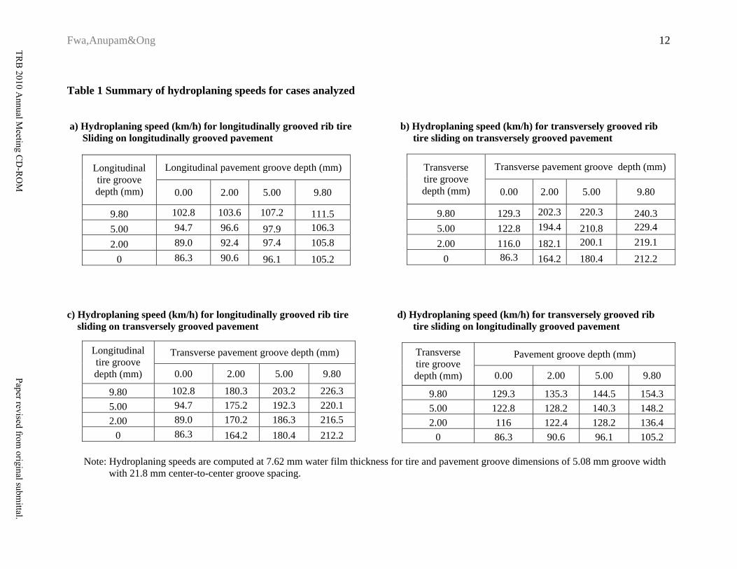
Table 1 Summary of hydroplaning speeds for cases analyzed a) Hydroplaning speed (km/h) for longitudinally grooved rib tire b) Hydroplaning speed (km/h) for transversely grooved rib Sliding on longitudinally grooved pavement tire sliding on transversely grooved pavement
Transverse pavement groove depth (mm) Transverse tire groove depth (mm) 0.00 2.00 5.00 9.80
9.80 129.3 202.3 220.3 240.3 5.00 122.8 194.4 210.8 229.4 2.00 116.0 182.1 200.1 219.1
0 86.3 164.2 180.4 212.2
Longitudinal pavement groove depth (mm) Longitudinal tire groove depth (mm) 0.00 2.00 5.00 9.80
9.80 102.8 103.6 107.2 111.5 5.00 94.7 96.6 97.9 106.3 2.00 89.0 92.4 97.4 105.8
0 86.3 90.6 96.1 105.2
c) Hydroplaning speed (km/h) for longitudinally grooved rib tire d) Hydroplaning speed (km/h) for transversely grooved rib sliding on transversely grooved pavement tire sliding on longitudinally grooved pavement
Transverse pavement groove depth (mm) Longitudinal tire groove depth (mm) 0.00 2.00 5.00 9.80
9.80 102.8 180.3 203.2 226.3 5.00 94.7 175.2 192.3 220.1 2.00 89.0 170.2 186.3 216.5
0 86.3 164.2 180.4 212.2
Pavement groove depth (mm) Transverse tire groove depth (mm) 0.00 2.00 5.00 9.80
9.80 129.3 135.3 144.5 154.3 5.00 122.8 128.2 140.3 148.2 2.00 116 122.4 128.2 136.4
0 86.3 90.6 96.1 105.2
Note: Hydroplaning speeds are computed at 7.62 mm water film thickness for tire and pavement groove dimensions of 5.08 mm groove width with 21.8 mm center-to-center groove spacing.
TRB
2010 Annual M
eeting CD
-RO
MPaper revised from
original submittal.

Fwa,Anupam&Ong 13
Table 2 Average rates of increase in hydroplaning speed per unit increase in pavement groove depth or tire groove depth
Hydroplaning Speed Increase per unit Increase in Pavement Groove Depth
Hydroplaning Speed Increase per unit Increase in Tire Groove Depth
Condition km/h per mm depth
km/h per mm depth Condition
(A1) Longitudinally grooved pavement & smooth tire 1.93 1.68 (B1) Longitudinally grooved tire
tread & smooth pavement
(A2) Longitudinally grooved pavement & longitudinally grooved tire
1.26 1.03 (B2) Longitudinally grooved tire
tread & longitudinally grooved pavement
(A3) Longitudinally grooved pavement & transversely grooved tire
2.41 1.80 (B3) Longitudinally grooved tire
tread & transversely grooved pavement
(A4) Transversely grooved pavement & smooth tire 12.86 4.39 (B4) Transversely grooved tire
tread & smooth pavement
(A5) Transversely grooved pavement & longitudinally grooved tire
12.80 4.84 (B5) Transversely grooved tire
tread & longitudinally grooved pavement
(A6) Transversely grooved pavement & transversely grooved tire
10.91 3.61 (B6) Transversely grooved tire
tread & transversely grooved pavement
Note: Hydroplaning speeds are computed at 7.62 mm water film thickness for tire and pavement groove dimensions of 5.08 mm groove width with 21.8 mm center-to-center groove spacing.
TRB 2010 Annual Meeting CD-ROM Paper revised from original submittal.

Fwa,Anupam&Ong 14
Table 3 Relative effectiveness of measures in reducing hydroplaning risk
Description of
Measure
Pavement Grooving*
Tire Tread Grooving*
Hydroplaning Speed (km/h)
Hydroplaning Risk
Ranking** (C1) Smooth tire on smooth pavement
surface 0 0 86.3 1
(C2) Longitudinally grooved tire on smooth pavement 0 L 102.8 2
(C3) Smooth tire on longitudinally grooved pavement L 0 105.2 3
(C4) Longitudinally grooved tire on longitudinally grooved pavement
L L 111.5 4
(C5) Transversely grooved tire on smooth pavement 0 T 129.3 5
(C6) Transversely grooved tire on longitudinally grooved pavement
L T 154.3 6
(C7) Smooth tire on transversely grooved pavement T 0 212.2 7
(C8) Longitudinally grooved tire on transversely grooved pavement T L 226.3 8
(C9) Transversely grooved tire on transversely grooved pavement T T 240.3 9
Note: Hydroplaning speeds are computed at 7.62 mm water film thickness for the following tire and pavement groove dimensions: 5.08 mm groove width, 21.8 mm center-to-center groove spacing, 9.8 mm groove depth.
TRB 2010 Annual Meeting CD-ROM Paper revised from original submittal.

Fwa,Anupam&Ong 15
Table 4 Effectiveness grouping of measures
Grouping Description of Measure
Hydroplaning Speed (km/h) Key Grooving Feature
I (C1) Smooth tire on smooth pavement surface 86.3 Ungrooved tire and
ungrooved pavement
(C2) Longitudinally grooved tire on smooth pavement 102.8
(C3) Smooth tire on longitudinally grooved pavement
105.2 II
(C4) Longitudinally grooved tire on longitudinally grooved pavement
111.5
Longitudinally grooved tire or longitudinally grooved pavement
(C5) Transversely grooved tire on smooth pavement 129.3
III (C6) Transversely grooved tire on longitudinally grooved pavement
154.3
Transversely grooved tire
(C7) Smooth tire on transversely grooved pavement 212.2
(C8) Longitudinally grooved tire on transversely grooved pavement
226.3 IV
(C9) Transversely grooved tire on transversely grooved pavement
240.3
Transversely grooved pavement
Note: Hydroplaning speeds are computed at 7.62 mm water film thickness for the following tire and pavement groove dimensions: 5.08 mm groove width, 21.8 mm center-to-center groove spacing, and 9.8 mm groove depth.
TRB 2010 Annual Meeting CD-ROM Paper revised from original submittal.

Fwa,Anupam&Ong 16
Table 5 Simplified analysis of difference in water discharge capacities of
tire tread grooves and pavement grooves
Groove depth (mm)
Discharge capacity of simulated grooved tire on smooth pavement (m3/s)
Discharge capacity of simulated smooth tire on grooved pavement (m3/s)
5 1.26E-04 1.98E-04 3 6.80E-05 8.43E-05 2 5.15E-05 6.72E-05
0.5 4.94E-07 6.13E-07 Note: All grooves have identical plan dimensions of 5.08 mm in width and 21.8 mm in center-to-center groove spacing.
TRB 2010 Annual Meeting CD-ROM Paper revised from original submittal.

Fwa,Anupam&Ong 17
(a) Pneumatic Tire Model
Tire Inflation Pressure on Inside Walls of
Aircraft Tire, pt Aircraft Wheel
Load, P
Speed, v Pavement Surface (Rigid)
Fluid-Structure Interface
(See Figure 1(b) for details)
Pavement Surface (Moving wall with
speed v)
Water Velocity inlet with speed v
Tire Tread Face (Fluid-Structure
Interface)
Pressure outlet at atmospheric pressure
(b) Fluid Model
Figure 1 3-dimensional finite element hydroplaning simulation
model [after reference (12)]
TRB 2010 Annual Meeting CD-ROM Paper revised from original submittal.
Fwa,Anupam&Ong
18
0
50
100
150
200
250
300
0 500 1000 1500 2000
Tire Pressure (kPa)
Hyd
ropl
anin
g Sp
eed
(km
/h)
Proposed Model
NASA equation
Experiment (Horneand Joyner, 1965)
Simulation Model
NASA Equation Experimental Data (Horne & Joyner 1965)
Figure 2 Validation of computed hydroplaning speeds by simulation
model [after reference (13)]
TRB 2010 Annual Meeting CD-ROM Paper revised from original submittal.

Fwa,Anupam&Ong
19
60
85
110
135
160
185
210
235
260
0 2 4 6 8 10
60
85
110
135
160
185
210
235
260
0 2 4 6 8 10
b) For transversely grooved pavement and tire
Hyd
ropl
anin
g sp
eed
(km
/h)
60
75
90
105
120
0 2 4 6 8 10
a) For longitudinally grooved tire and pavement
60
85
110
135
160
185
210
235
0 2 4 6 8 10
c) For longitudinally grooved tire on transversely grooved pavement
d) For transversely grooved tire on longitudinally grooved pavement
Pavement groove depth (mm) Pavement groove depth (mm)
Pavement groove depth (mm) Pavement groove depth (mm)
Hyd
ropl
anin
g sp
eed
(km
/h)
Hyd
ropl
anin
g sp
eed
(km
/h)
Hyd
ropl
anin
g sp
eed
(km
/h)
9.8 mm 5.0 mm 2.0 mm 0.0 mm
Tire groove depth9.8 mm 5.0 mm 2.0 mm 0.0 mm
Tire groove depth
9.8 mm 5.0 mm 2.0 mm 0.0 mm
Tire groove depth
9.8 mm 5.0 mm 2.0 mm 0.0 mm
Tire groove depth
Figure 3 Hydroplaning speed and pavement groove depth at different tire groove depth
TRB
2010 Annual M
eeting CD
-RO
MPaper revised from
original submittal.

Fwa,Anupam&Ong
20
60
85
110
135
160
185
210
235
260
0 2 4 6 8 10
60
85
110
135
160
185
210
235
260
0 2 4 6 8 10
60
85
110
135
160
185
210
235
260
0 2 4 6 8 10
60
75
90
105
120
0 2 4 6 8 10
a) For Longitudinally grooved tire and pavement b) For transversely grooved pavement and tire H
ydro
plan
ing
spee
d (k
m/h
)
Hyd
ropl
anin
g sp
eed
(km
/h)
Pavement groove depth9.8 mm 5.0 mm 2.0 mm 0.0 mm
9.8 mm Pavement groove depth
5.0 mm 2.0 mm 0.0 mm
Tire groove depth (mm) Tire groove depth (mm) c) For Longitudinally grooved tire on transversely
grooved pavement d) For transversely grooved tire on longitudinally
grooved pavement
Hyd
ropl
anin
g sp
eed
(km
/h)
Hyd
ropl
anin
g sp
eed
(km
/h)
9.8 mm Pavement groove depth
5.0 mm 2.0 mm 0.0 mm
9.8 mm Pavement groove depth
5.0 mm 2.0 mm 0.0 mm
Tire groove depth (mm) Tire groove depth (mm)
Figure 4 Hydroplaning speed and tire groove depth at different pavement groove depth
TRB
2010 Annual M
eeting CD
-RO
MPaper revised from
original submittal.

Fwa,Anupam&Ong
21
Pavement groove depth
Cylinder
Pavement top surface
H1 H2
Water level at atmospheric pressure
H2
Cylinder
Pavement top surface
H1
Tire groove depth
Pavement top surface
Water level at atmospheric pressure
a) Smooth tire on grooved pavement surface b) Grooved tire on plane pavement surface
Figure 5 Simplified comparisons of discharge capacities of tire and pavement grooves
TRB
2010 Annual M
eeting CD
-RO
MPaper revised from
original submittal.
Related Documents