1 | Page | INTERNSHIP REPORT | RCC BOX FOR A ROAD UNDER BRIDGE A. INTRODUCTION It is well known that railway tracks have to cross through the roads in and around highly populated, well-built cities and towns so a level crossing is provided in those points but these level crossings may be manned or unmanned, and further causes a traffic jam when a train has to pass by. As both population and traffic are increasing day by day delays and the risk of accidents at the level crossings are also increasing, on Indian Railways. About 30% of consequential train accidents were at level crossings, in terms of causalities it contributes 60%. So Indian Railways has decided to go for road over bridges (ROB’s) and road under bridges (RUB’s) where ever necessary in populated cities. As the cities are well built the land acquisition for construction of ROB is difficult and sometimes not possible, so under such cases engineers go for RUB’s. Sometimes the railway lines or the roads are constructed in embankment which comes in the way of natural flow of storm water (from existing drainage channels) or city sewages, as such flow cannot be obstructed and some kind of cross drainage works are required to be provided to allow water to pass across the embankment. Culverts are provided to accomplish such flow across the rail lines and roadways; small and major bridges depending on their span which in turn depends on the discharge, if span is small engineers go for box or slab bridges. To construct RUB’s with minimum disruption to train services and road traffic is a challenge to the Engineers. Methods adopted for construction of these structures are 1. Cut and cover method 2. Box pushing method 3. Restricted Height Girder method Box pushing technique is most widely used because of its numerous advantages over the other conventional method i.e. cut and cover method, box pushing technique is safer to construct in a busy junction of rail and road over conventional method. In Box pushing technique, R.C.C. boxes in segments are cast outside and pushed through the heavy embankments of Rail or Road by Jacking. The required thrust is generated through thrust bed, as well as line and level of precast boxes is also controlled. This underpass RCC Bridge is pushed into embankment by means of hydraulic equipment which is detailed explained in this report, since the availability of land in the city is less, such type of bridge utilizes less space for its construction. Hence constructing Underpass Bridge is a better option where there is a constraint of space or Land. In this report a detailed explanation of a RCC Box RUB construction project through an embankment of a rail line located in Mettuguda, Secunderabad.

Welcome message from author
This document is posted to help you gain knowledge. Please leave a comment to let me know what you think about it! Share it to your friends and learn new things together.
Transcript
1 | P a g e | INTERNSHIP REPORT |
RCC BOX FOR A ROAD UNDER BRIDGE
A. INTRODUCTION
It is well known that railway tracks have to cross through the roads in and around highly
populated, well-built cities and towns so a level crossing is provided in those points but these
level crossings may be manned or unmanned, and further causes a traffic jam when a train has
to pass by. As both population and traffic are increasing day by day delays and the risk of
accidents at the level crossings are also increasing, on Indian Railways. About 30% of
consequential train accidents were at level crossings, in terms of causalities it contributes 60%.
So Indian Railways has decided to go for road over bridges (ROB’s) and road under bridges
(RUB’s) where ever necessary in populated cities. As the cities are well built the land acquisition
for construction of ROB is difficult and sometimes not possible, so under such cases engineers
go for RUB’s.
Sometimes the railway lines or the roads are constructed in embankment which comes in the
way of natural flow of storm water (from existing drainage channels) or city sewages, as such
flow cannot be obstructed and some kind of cross drainage works are required to be provided
to allow water to pass across the embankment. Culverts are provided to accomplish such flow
across the rail lines and roadways; small and major bridges depending on their span which in
turn depends on the discharge, if span is small engineers go for box or slab bridges. To construct
RUB’s with minimum disruption to train services and road traffic is a challenge to the Engineers.
Methods adopted for construction of these structures are
1. Cut and cover method
2. Box pushing method
3. Restricted Height Girder method
Box pushing technique is most widely used because of its numerous advantages over the other
conventional method i.e. cut and cover method, box pushing technique is safer to construct in a
busy junction of rail and road over conventional method. In Box pushing technique, R.C.C. boxes
in segments are cast outside and pushed through the heavy embankments of Rail or Road by
Jacking. The required thrust is generated through thrust bed, as well as line and level of precast
boxes is also controlled. This underpass RCC Bridge is pushed into embankment by means of
hydraulic equipment which is detailed explained in this report, since the availability
of land in the city is less, such type of bridge utilizes less space for its construction. Hence
constructing Underpass Bridge is a better option where there is a constraint of space or
Land.
In this report a detailed explanation of a RCC Box RUB construction project through an
embankment of a rail line located in Mettuguda, Secunderabad.
2 | P a g e | INTERNSHIP REPORT |
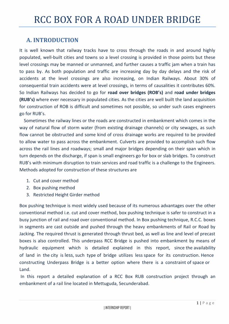
B. DETAILED REPORT
In this report a detailed explanation of a RCC Box RUB construction project under a railway
embankment in Mettuguda (Secundrabad, India) is given. This report is divided into following
parts
Site selection and description
Design
Construction and Execution
Time and progress of work
Safety and precautionary measures
Advantages and Limitations
References

3 | P a g e | INTERNSHIP REPORT |
1. SITE SELECTION AND DESCRIPTION
Secundrabad (Hyderabad, India) is a highly populated, well-built city. It is the capital of state of
Telangana, headquarters for many government organizations, MNCs, industries and many other
businesses, so it is a center of attraction for a large work force. So there is a prevailing need of
an efficient road system. Secunderabad is also headquarters of south central railways, so
Secundrabad railway station is busiest station in this region. So a need for RUB’s and ROB’s for
all its level crossings is must.
The site chosen for this RUB construction had a long pending need of rail crossing as road
width extension was being carried by state government to accommodate the increasing traffic
volume. Construction of ROB is highly impractical as land acquisition is difficult and ROB is too
costly. Also there is also an active metro rail project under construction in that place and as the
current rail line is on elevated portion engineers chose to go for a road under bridge (RUB)
construction using box pushing technique which causes minimum disruption to train services
and road traffic
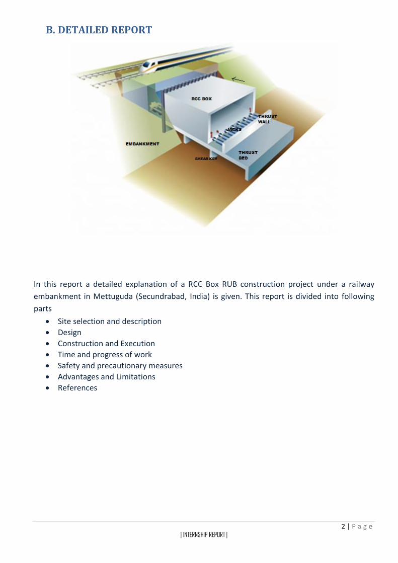
As you can see in this satellite image of construction site below, how well built is the area
around the location of the project is, so the construction of a RUB was must. Executive Engineer
stated that there was a lot demand from political side and the local authorities & public.
Satellite image of RUB construction site connecting Boiguda-Mettuguda in Secundrabad, courtesy google maps
4 | P a g e | INTERNSHIP REPORT |
Satellite map of RUB construction site connecting Boiguda-Mettuguda in Secundrabad, courtesy google maps
5 | P a g e | INTERNSHIP REPORT |
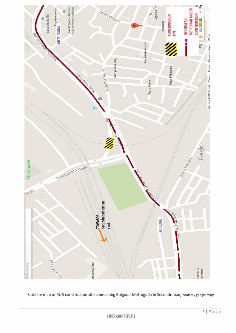
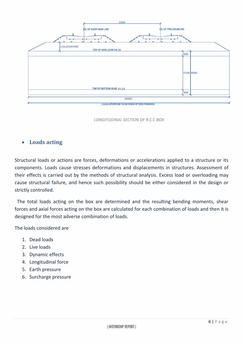
2. DESIGN OF THE RCC BOX
Design data
Size of the box 10.5 m X 5.15 m
Length of the box 24 m
Thickness of top slab 0.9 m
Thickness of bottom slab 0.9 m
Thickness of end vertical walls 0.9 m
R.L of Rail level 100.1 m
R.L of formation level 99.39 m
R.L of invert level 92.33 m
Grade of concrete M40
Grade of steel Fe415
Clear cover to reinforcement 50 mm
Density of soil 1.9 T/m3
Angle of internal friction 30o
Unit weight of ballast 19.2 T/m3
Assumptions
1. Density of concrete = 2.5 T/cubic meter
2. Density of Soil = 1.9 T/cubic meter
3. Loading standard = 25T - 2008 LOAD As per (Indian rail code standards)
6 | P a g e | INTERNSHIP REPORT |
LONGITUDINAL SECTION OF R.C.C BOX
Loads acting
Structural loads or actions are forces, deformations or accelerations applied to a structure or its
components. Loads cause stresses deformations and displacements in structures. Assessment of
their effects is carried out by the methods of structural analysis. Excess load or overloading may
cause structural failure, and hence such possibility should be either considered in the design or
strictly controlled.
The total loads acting on the box are determined and the resulting bending moments, shear
forces and axial forces acting on the box are calculated for each combination of loads and then it is
designed for the most adverse combination of loads.
The loads considered are
1. Dead loads
2. Live loads
3. Dynamic effects
4. Longitudinal force
5. Earth pressure
6. Surcharge pressure

7 | P a g e | INTERNSHIP REPORT |
DEAD LOADS
Dead loads are those that are constant in magnitude and fixed in location throughout the lifetime
of the structure. Usually the major part of the dead load is the self-weight of the structure. The
dead load can be calculated accurately from the design configuration, dimension of the structure
and density of the material, rail load, sleeper load, ballast load. The load due to weight of earth
above box (earth cushion) also contributes to dead weight it is called cushion load.
Superimposed load
Tracks
One track = 2 rails = 2*60 kg/m = 120 kg/m
For two tracks = 2*120 = 240 kg/m
Sleeper
Spacing = 0.66 m
For 1 m = 0.23∗0.3∗2.75
0.66= 0.287 m3
For two tracks = 2*0.287 = 0.574 m3
Hence load due to sleeper = 0.574*2.5 =1.435
T/m
Total load = track load + sleeper load = 0.24 + 1.435 =1.675 T/m
Dispersion width due to track load, assuming 1H: 2V slope
Dispersion width for one track = 2.75 + 1.01 + 0.3 (depth of ballast) = 4.06 m
Dispersion width for two tracks = 2*4.06 = 8.12 m
Load due to track (LT) = 1.675
8.12 = 0.206 T/m2
Ballast
Cushion thickness = 400 mm
Bottom width of ballast = 2.75 + 0.7 + 0.7 + 2*0.15 = 4.45 m
Volume of ballast = [3.05+4.45]∗0.7
2 *1- 0.287 (volume of sleeper) = 2.34 m3
Volume of ballast for two tracks = 2*2.34 = 4.68 m3
CROSS SECTION OF TRACK
8 | P a g e | INTERNSHIP REPORT |
Load due to ballast = 4.68*1.92(unit weight of ballast) = 9 T
Dispersion width due to ballast load, assuming 1H: 2V slope
Dispersion width = 4.45 + 1.01 = 5.46 m
Dispersion width for two tracks = 5.46 + 5.3 =10.76 m
Load due to ballast (BL) = 9
10.76∗1 = 0.836 T/m2
Superimposed load = LT + BL = 0.206 + 0.836 = 1.042 T/m2
As per standard books of railways, the superimposed load on each track should be 6.75 T/m
For two tracks superimposed load = 2*6.75 =13.5 T/m
Superimposed load = 13.5
10.76 = 1.255 T/m2
Superimposed load is the greater value of the above
∴ Superimposed load (SL) = 1.255 T/m2
Weight of earth fill (WE) = 1.01 X 1.9 = 1.919 T/m2
Weight of top slab (WTS) = 0.9 X 2.5 = 2.25 T/m2
Weight of vertical walls (WV) = 6.05∗1.8∗2.5
11.4= 2.39 T/m2
Weight of wearing course (WW) = 10.5∗0.5∗1
11.4∗1= 0.46 T/M2
From clause 2.3.2.1 of Indian railway bridge rule
Assume weight of decking for roadway and weight of footpath (WF) = 0.5 T/m2
Therefore dead load on top slab = SL + WE + WTS = 1.255 + 1.919 +2.25
= 5.424 T/m2
Therefore dead load on bottom slab = SL + WE + WTS + WV + WW + WF
= 1.255 + 1.919 + 2.25 + 2.39 + 0.46 + 0.5 = 8.774 T/m2
9 | P a g e | INTERNSHIP REPORT |
LIVE LOAD
Live loads are consists of occupancy loads in buildings and traffic loads on bridges. They may be
fully or partially in place or not present at all and may change its location. Human, chair, table,
computer, bed, furniture, train etc are live loads. Live loads may change its present location as
they are not lifetime part of a structure. So, in structural design live loads are provided a larger
safety factor than the others.
Effective span of the box = 11.4 m
Effective span for shear force = 12.3 m
From appendix XXIII of bridge rules,
Maximum load for Bending moment = 130.7+ 140.4−130.7
1∗ 0.4 =134.57 T
Maximum load for Shear Force = 162+ 170.3−162
1∗ 0.3 = 164.49 T
Depth of fill = 1.01+ 0.3 (depth of ballast) =1.31 m
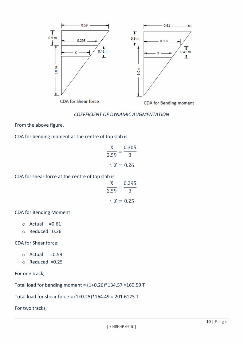
DYNAMIC EFFECT
For Broad Gauge (BG) and Meter Gauge (MG) Railway:
The augmentation in load due to dynamic effects should be considered by adding a load Equivalent
to a Coefficient of Dynamic Augment (CDA) multiplied by the live load giving the maximum stress
in the member under consideration. The CDA should be obtained as follows and shall be applicable
up to 160 km/h on BG and 100 km/h on MG.
For single track spans:
CDA= 0.15 +8
6+L
Where, L is the loaded length of span in metres for the position of the train giving the maximum
stress in the member under consideration.
Depth of fill= 1.31 m
From clause 2.4.2.1 (b) of Indian railway bridge rules
10 | P a g e | INTERNSHIP REPORT |
COEFFICIENT OF DYNAMIC AUGMENTATION
From the above figure,
CDA for bending moment at the centre of top slab is
X
2.59=
0.305
3
∴ 𝑋 = 0.26
CDA for shear force at the centre of top slab is
X
2.59=
0.295
3
∴ 𝑋 = 0.25
CDA for Bending Moment:
o Actual =0.61
o Reduced =0.26
CDA for Shear force:
o Actual =0.59
o Reduced =0.25
For one track,
Total load for bending moment = (1+0.26)*134.57 =169.59 T
Total load for shear force = (1+0.25)*164.49 = 201.6125 T
For two tracks,
11 | P a g e | INTERNSHIP REPORT |
Total load for bending moment = 2*169.59 = 339.18 T
Total load for shear force = 2*201.6125 =403.225 T
As total load due to shear force is maximum.
We consider, total load for shear force = 403.225 T
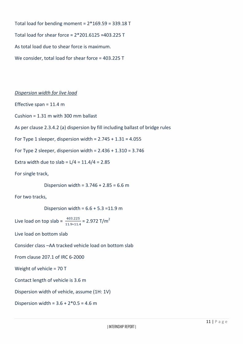
Dispersion width for live load
Effective span = 11.4 m
Cushion = 1.31 m with 300 mm ballast
As per clause 2.3.4.2 (a) dispersion by fill including ballast of bridge rules
For Type 1 sleeper, dispersion width = 2.745 + 1.31 = 4.055
For Type 2 sleeper, dispersion width = 2.436 + 1.310 = 3.746
Extra width due to slab = L/4 = 11.4/4 = 2.85
For single track,
Dispersion width = 3.746 + 2.85 = 6.6 m
For two tracks,
Dispersion width = 6.6 + 5.3 =11.9 m
Live load on top slab = 403.225
11.9∗11.4 = 2.972 T/m2
Live load on bottom slab
Consider class –AA tracked vehicle load on bottom slab
From clause 207.1 of IRC 6-2000
Weight of vehicle = 70 T
Contact length of vehicle is 3.6 m
Dispersion width of vehicle, assume (1H: 1V)
Dispersion width = 3.6 + 2*0.5 = 4.6 m

12 | P a g e | INTERNSHIP REPORT |
Live load on bottom slab = 70
12.3∗4.6 = 1.24 T/m2
∴ Live load on top slab is 2.972 T/m2
∴ Live load on bottom slab is 1.24 T/m2
LONGITUDINAL FORCE
Where a structure carries railway track, provision as under shall be made for the longitudinal loads
arising from any one or more of the following causes:
a) The tractive effort of the driving wheels of locomotives;
b) The braking force resulting from the application of the brakes to all braked wheels;
c) Resistance to the movement of the bearings due to change of temperature and
deformation of the bridge girder. Roller, PTFE or elastomeric bearings may preferably be
provided to minimize the longitudinal force arising on this account.
d) Forces due to continuation of LWR/CWR over the bridges.
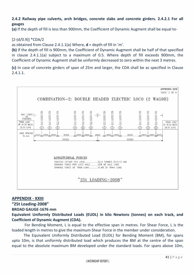
From appendix XXII sheet 2/4 of Indian railway bridge rules
Tractive effort per loco on track =52 T
For two tracks, tractive effort =2*52=104 ~ 105 T
Dispersion width for longitudinal load
At top slab centre level,
For single tack,
Dispersion width = 3 + 1.01 + 0.45 = 4.46 m
For two tracks,
Dispersion width = 4.46 + 5.3 = 9.76 m
Hence horizontal force per meter at the top slab centre = 105
9.76 = 10.758 T
EARTH PRESSURE
Lateral earth pressure is the pressure that soil exerts in the horizontal direction. The lateral earth
pressure is important because it affects the consolidation behavior and strength of the soil and
because it is considered in the design of geotechnical engineering structures such as retaining
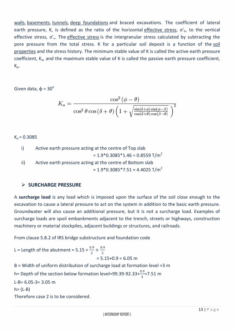
13 | P a g e | INTERNSHIP REPORT |
walls, basements, tunnels, deep foundations and braced excavations. The coefficient of lateral
earth pressure, K, is defined as the ratio of the horizontal effective stress, σ’h, to the vertical
effective stress, σ’v. The effective stress is the intergranular stress calculated by subtracting the
pore pressure from the total stress. K for a particular soil deposit is a function of the soil
properties and the stress history. The minimum stable value of K is called the active earth pressure
coefficient, Ka, and the maximum stable value of K is called the passive earth pressure coefficient,
Kp.
Given data, φ = 30o
Ka = 0.3085
i) Active earth pressure acting at the centre of Top slab
= 1.9*0.3085*1.46 = 0.8559 T/m2
ii) Active earth pressure acting at the centre of Bottom slab
= 1.9*0.3085*7.51 = 4.4025 T/m2
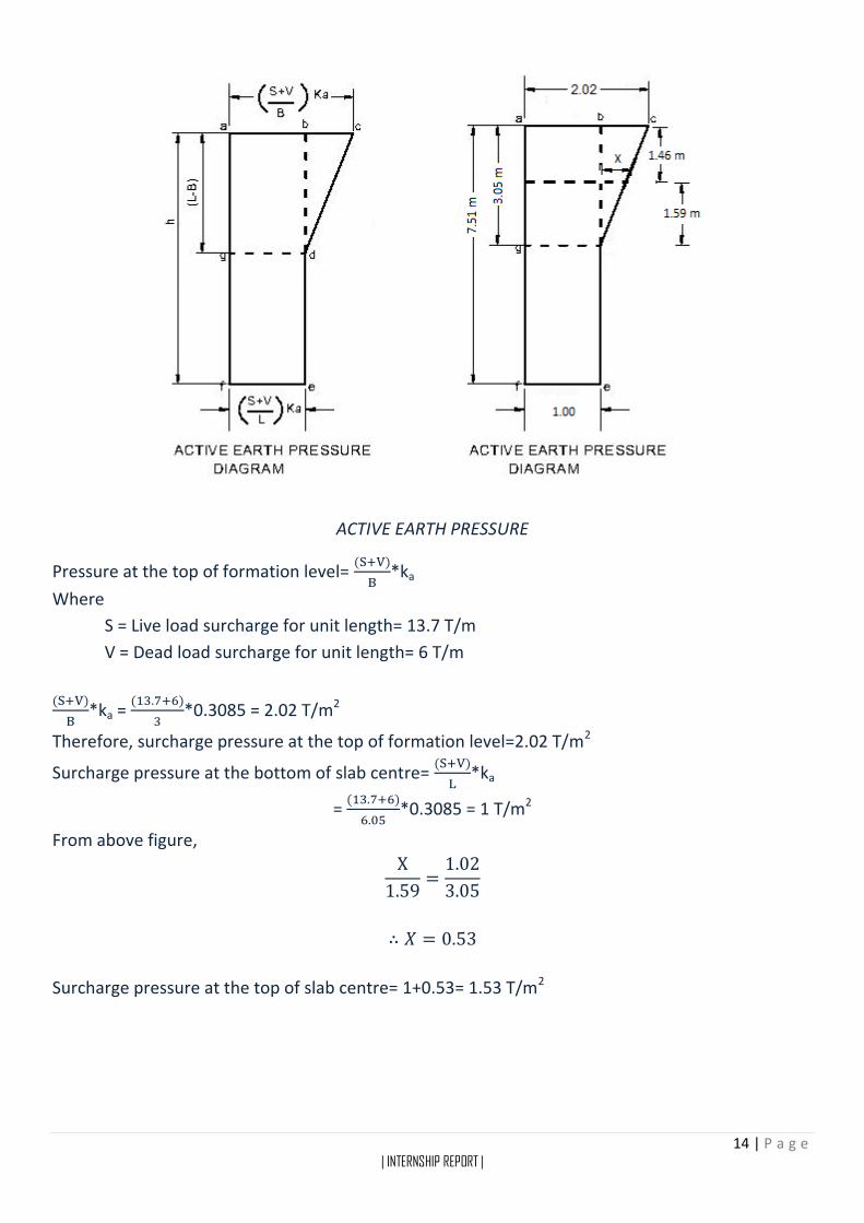
SURCHARGE PRESSURE
A surcharge load is any load which is imposed upon the surface of the soil close enough to the
excavation to cause a lateral pressure to act on the system in addition to the basic earth pressure.
Groundwater will also cause an additional pressure, but it is not a surcharge load. Examples of
surcharge loads are spoil embankments adjacent to the trench, streets or highways, construction
machinery or material stockpiles, adjacent buildings or structures, and railroads.
From clause 5.8.2 of IRS bridge substructure and foundation code
L = Length of the abutment = 5.15 + 0.9
2+
0.9
2
= 5.15+0.9 = 6.05 m
B = Width of uniform distribution of surcharge load at formation level =3 m
h= Depth of the section below formation level=99.39-92.33+0.9
2=7.51 m
L-B= 6.05-3= 3.05 m
h> (L-B)
Therefore case 2 is to be considered.
14 | P a g e | INTERNSHIP REPORT |
ACTIVE EARTH PRESSURE
Pressure at the top of formation level= (S+V)
B*ka
Where
S = Live load surcharge for unit length= 13.7 T/m
V = Dead load surcharge for unit length= 6 T/m
(S+V)
B*ka =
(13.7+6)
3*0.3085 = 2.02 T/m2
Therefore, surcharge pressure at the top of formation level=2.02 T/m2
Surcharge pressure at the bottom of slab centre= (S+V)
L*ka
= (13.7+6)
6.05*0.3085 = 1 T/m2
From above figure,
X
1.59=
1.02
3.05
∴ 𝑋 = 0.53
Surcharge pressure at the top of slab centre= 1+0.53= 1.53 T/m2
15 | P a g e | INTERNSHIP REPORT |
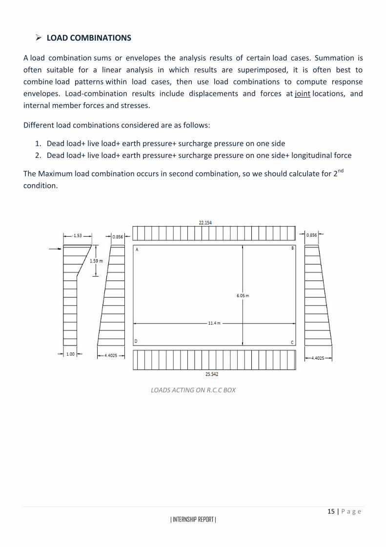
LOAD COMBINATIONS
A load combination sums or envelopes the analysis results of certain load cases. Summation is
often suitable for a linear analysis in which results are superimposed, it is often best to
combine load patterns within load cases, then use load combinations to compute response
envelopes. Load-combination results include displacements and forces at joint locations, and
internal member forces and stresses.
Different load combinations considered are as follows:
1. Dead load+ live load+ earth pressure+ surcharge pressure on one side
2. Dead load+ live load+ earth pressure+ surcharge pressure on one side+ longitudinal force
The Maximum load combination occurs in second combination, so we should calculate for 2nd
condition.
LOADS ACTING ON R.C.C BOX
16 | P a g e | INTERNSHIP REPORT |
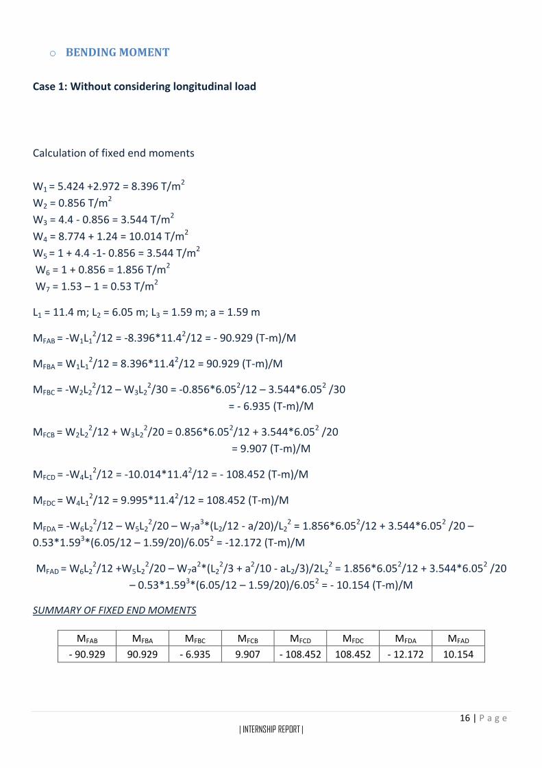
o BENDING MOMENT
Case 1: Without considering longitudinal load
Calculation of fixed end moments
W1 = 5.424 +2.972 = 8.396 T/m2
W2 = 0.856 T/m2
W3 = 4.4 - 0.856 = 3.544 T/m2
W4 = 8.774 + 1.24 = 10.014 T/m2
W5 = 1 + 4.4 -1- 0.856 = 3.544 T/m2
W6 = 1 + 0.856 = 1.856 T/m2
W7 = 1.53 – 1 = 0.53 T/m2
L1 = 11.4 m; L2 = 6.05 m; L3 = 1.59 m; a = 1.59 m
MFAB = -W1L12/12 = -8.396*11.42/12 = - 90.929 (T-m)/M
MFBA = W1L12/12 = 8.396*11.42/12 = 90.929 (T-m)/M
MFBC = -W2L22/12 – W3L2
2/30 = -0.856*6.052/12 – 3.544*6.052 /30
= - 6.935 (T-m)/M
MFCB = W2L22/12 + W3L2
2/20 = 0.856*6.052/12 + 3.544*6.052 /20
= 9.907 (T-m)/M
MFCD = -W4L12/12 = -10.014*11.42/12 = - 108.452 (T-m)/M
MFDC = W4L12/12 = 9.995*11.42/12 = 108.452 (T-m)/M
MFDA = -W6L22/12 – W5L2
2/20 – W7a3*(L2/12 - a/20)/L22 = 1.856*6.052/12 + 3.544*6.052 /20 –
0.53*1.593*(6.05/12 – 1.59/20)/6.052 = -12.172 (T-m)/M
MFAD = W6L22/12 +W5L2
2/20 – W7a2*(L22/3 + a2/10 - aL2/3)/2L2
2 = 1.856*6.052/12 + 3.544*6.052 /20
– 0.53*1.593*(6.05/12 – 1.59/20)/6.052 = - 10.154 (T-m)/M
SUMMARY OF FIXED END MOMENTS
MFAB MFBA MFBC MFCB MFCD MFDC MFDA MFAD
- 90.929 90.929 - 6.935 9.907 - 108.452 108.452 - 12.172 10.154

17 | P a g e | INTERNSHIP REPORT |
Bending moment at mid span
Assuming each member as simply supported
MAB = W1L12/8 = 8.396*11.42/8 = 136.393 (T-m)/M
MCD = W4L12/8 = 10.014*11.42/8 = 162.677 (T-m)/M
MBC = W2L22/8 + W3L2
2/16 = 0.856*6.052/8 + 3.544*6.052/16 = 12.024 (T-m)/M
MDA = W6L22/8 + W5L2
2/16 + W7a2/12 – W [-a-0.5L2]3/6a = 1.856*6.052/8 + 3.544*6.052/16 +
0.53*1.592/12 – 0.53(-1.59-0.5*6.05)3/ (6*1.59)
= 22.162 (T-m)/M
BENDING MOMENT AT MID SPAN
MAB MBC MCD MDA 136.393 12.024 162.677 22.162
Calculation of distribution factor
KAB = I
L =
I
11.4
KAB = KBA = KDC = KCD
KAD = I
L =
I
6.05
KAD = KDA = KBC = KCB
DISTRIBUTION FACTOR
JOINT MEMBER RELATIVE STIFFNESS
SUMMATION DISTRIBUTION
FACTOR
A AD I/6.05
0.253I 0.653
AB I/11.4 0.347
B BA I/11.4
0.253I 0.347
BC I/6.05 0.653
C CB I/6.05
0.253I 0.653
CD I/11.4 0.347
D DC I/11.4
0.253I 0.347
DA I/6.05 0.653

18 | P a g e | INTERNSHIP REPORT |
MOMENT DISTRIBUTION METHOD 1
JOINT
MEMBER AD AB BA BC CB CD DC DA
D.F 0.653 0.347 0.347 0.653 0.653 0.347 0.347 0.653
F.E.M 10.154 -90.929 90.929 -6.935 9.907 -108.452 108.452 -12.172
Balancing 52.746 28.029 -29.389 -55.305 64.35 34.195 -33.409 -62.871
Carry over -31.436 -14.694 14.014 32.175 -27.652 -16.704 17.098 26.373
Balancing 30.123 16.007 -16.028 -30.161 28.964 15.391 -15.084 -28.386
Carry over -14.193 -8.014 8.004 14.482 -15.08 -7.542 7.7 15.062
Balancing 14.501 7.706 -7.803 -14.683 14.772 7.85 -7.898 -14.864
Carry over -7.432 -3.902 3.853 7.386 -7.342 -3.949 3.925 7.25
Balancing 7.401 3.933 -3.9 -7.339 7.373 3.918 -3.878 -7.297
Carry over -3.649 -1.95 1.966 3.686 -3.67 -1.939 1.959 3.7
Balancing 3.656 1.943 -1.961 -3.691 3.663 1.946 -1.964 -3.695
Carry over -1.848 -0.98 0.972 1.832 -1.846 -0.982 0.973 1.828
Balancing 1.847 0.981 -0.973 -1.831 1.847 0.981 -0.972 -1.829
Total 61.87 -61.87 60 -60 75.286 -75.287 76.902 -76.901
A B C D
BENDING MOMENT
MAD MAB MBA MBC MCB MCD MDC MDA
61.87 -61.87 60 -60 75.286 -75.286 76.901 -76.901
Case 2: considering only longitudinal load
LONGITUDINAL LOAD
Since there is no loading on spans and loading is acting only at joint A, fixed
moments due to loading are zero. There will be sway of the frame and moments will be
only due to the sway of the frame. The frame will sway towards right.
MFAD = -6EIδ/L22 = MFDA
MFBC = -6EIδ/L22 = MFCB
MFAD/ MFBC = 1
Assume, MFAD = -100 (T-m)/M
MFDA = -100 (T-m)/M
MFBC = -100 (T-m)/M = MFCB = -100 (T-m)/M
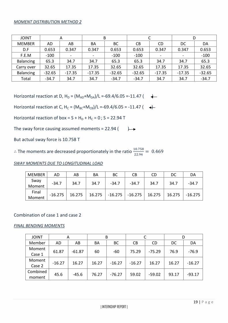
19 | P a g e | INTERNSHIP REPORT |
MOMENT DISTRIBUTION METHOD 2
JOINT A B C D
MEMBER AD AB BA BC CB CD DC DA
D.F 0.653 0.347 0.347 0.653 0.653 0.347 0.347 0.653
F.E.M -100 - - -100 -100 - - -100
Balancing 65.3 34.7 34.7 65.3 65.3 34.7 34.7 65.3
Carry over 32.65 17.35 17.35 32.65 32.65 17.35 17.35 32.65
Balancing -32.65 -17.35 -17.35 -32.65 -32.65 -17.35 -17.35 -32.65
Total -34.7 34.7 34.7 -34.7 -34.7 34.7 34.7 -34.7
Horizontal reaction at D, HD = (MAD+MDA)/L =-69.4/6.05 =-11.47 ( )
Horizontal reaction at C, HC = (MBC+MCB)/L =-69.4/6.05 = -11.47 ( )
Horizontal reaction of box = S + HD + HC = 0 ; S = 22.94 T
The sway force causing assumed moments = 22.94 ( )
But actual sway force is 10.758 T
∴ The moments are decreased proportionately in the ratio 10.758
22.94= 0.469
SWAY MOMENTS DUE TO LONGITUDINAL LOAD
MEMBER AD AB BA BC CB CD DC DA
Sway Moment
-34.7 34.7 34.7 -34.7 -34.7 34.7 34.7 -34.7
Final Moment
-16.275 16.275 16.275 -16.275 -16.275 16.275 16.275 -16.275
Combination of case 1 and case 2
FINAL BENDING MOMENTS
JOINT A B C D
Member AD AB BA BC CB CD DC DA
Moment Case 1
61.87 -61.87 60 -60 75.29 -75.29 76.9 -76.9
Moment Case 2
-16.27 16.27 16.27 -16.27 -16.27 16.27 16.27 -16.27
Combined moment
45.6 -45.6 76.27 -76.27 59.02 -59.02 93.17 -93.17
20 | P a g e | INTERNSHIP REPORT |
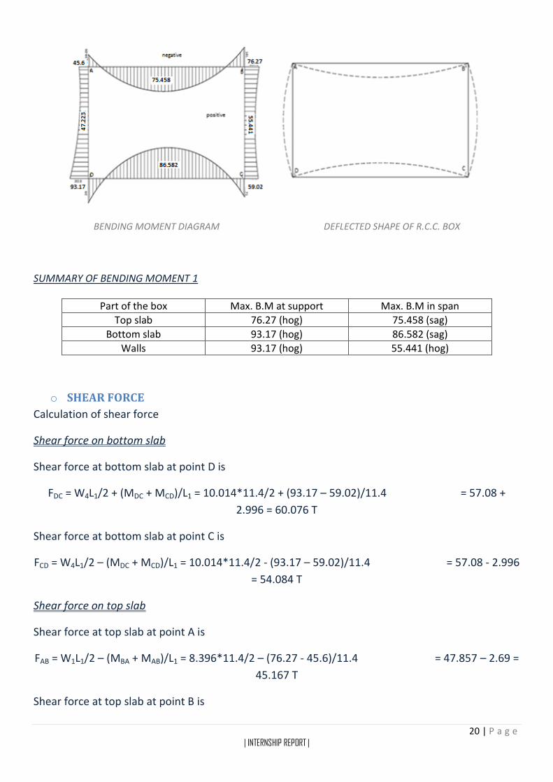
BENDING MOMENT DIAGRAM DEFLECTED SHAPE OF R.C.C. BOX
SUMMARY OF BENDING MOMENT 1
Part of the box Max. B.M at support Max. B.M in span
Top slab 76.27 (hog) 75.458 (sag)
Bottom slab 93.17 (hog) 86.582 (sag)
Walls 93.17 (hog) 55.441 (hog)
o SHEAR FORCE
Calculation of shear force
Shear force on bottom slab
Shear force at bottom slab at point D is
FDC = W4L1/2 + (MDC + MCD)/L1 = 10.014*11.4/2 + (93.17 – 59.02)/11.4 = 57.08 +
2.996 = 60.076 T
Shear force at bottom slab at point C is
FCD = W4L1/2 – (MDC + MCD)/L1 = 10.014*11.4/2 - (93.17 – 59.02)/11.4 = 57.08 - 2.996
= 54.084 T
Shear force on top slab
Shear force at top slab at point A is
FAB = W1L1/2 – (MBA + MAB)/L1 = 8.396*11.4/2 – (76.27 - 45.6)/11.4 = 47.857 – 2.69 =
45.167 T
Shear force at top slab at point B is

21 | P a g e | INTERNSHIP REPORT |
FBA = W1L1/2 + (MBA + MAB)/L1 = 8.396*11.4/2 + (76.27 – 45.6)/11.4
= 47.857 + 2.69 = 50.547 T
Shear force on wall AD
Shear force at wall AD at point D is
FD = - (MDA + MAD)/L2 + W6L2/2 + W5L2/3 + W7a2/ (6L2)
= - (-93.17 + 45.6)/6.05 + 1.856*6.05/2 + 3.544*6.05/3 + 0.53*1.592/ (6*6.05)
= 7.863 + 5.614 + 7.147 + 0.037 = 20.661 T
Shear force at wall AD at point A is
FA = (MDA + MAD)/L2 + W6L2/2 + W5L2/6 + W7a (L-a/3)/ (2L2)
= (-93.17 + 45.6)/6.05 + 1.856*6.05/2 + 3.544*6.05/3 + 0.53*1.59*(6.05 –
1.59/3)/ (2*6.05)
= - 7.863 + 5.614 + 7.147 + 0.384 = 5.282 T
Shear force on wall BC
Shear force at wall BC at point C is
FC = (MCB + MBC)/L2 + W2L2/2 + W3L2/3 = (59.02 – 76.27)/6.05 + 0.856*6.05/2 + 3.544*6.05/3
= - 2.851 + 2.589 + 7.147 = 6.885 T
Shear force at wall BC at point B is
FB = - (MCB + MBC)/L2 + W2L2/2 + W5L2/6 = - (59.02 – 76.27)/6.05 + 0.856*6.05/2 + 3.544*6.05/3
= 2.851 + 2.589 + 7.147 = 12.587 T
22 | P a g e | INTERNSHIP REPORT |
o AXIAL FORCE
An axial force is any force that directly acts on the centre axis of an object. These forces are
typically stretching force or compression force, depending on direction. In addition, when the
force load is even across the form’s geometric centre, it is concentric, and when it is uneven, it is
eccentric.
Calculation for Axial Force
Axial force on top slab
Axial force on top slab at A = shear force at wall at AD at A
∴ AFA = 5.282 T
Axial force on top slab at B = shear force at wall at BC at B
∴ AFB = 12.587 T
Axial force on top slab, AFAB = (AFA + AFB)/2 = (5.282 + 12.587)/2 = 8.934
∴AFAB =8.934 T
Axial force on bottom slab
Axial force on bottom slab at D = shear force at wall at AD at D
∴ AFD = 20.661 T
Axial force on bottom slab at C = shear force at wall at BC at C
∴ AFC = 6.885 T
Axial force on bottom slab, AFCD = (AFC + AFD)/2 = (20.661 + 6.885)/2 = 13.773
∴AFCD =13.773 T
Axial force on wall AD
Axial force on wall AD at A = shear force on top slab at A
∴ AFA = 45.167 T
Axial force on wall AD at D = shear force on bottom slab at D
∴ AFD =60.076 T
Axial force on wall AD, AFAD = (AFA + AFD)/2 = (45.167 + 60.076)/2 =52.622
∴AFAB =52.622 T

23 | P a g e | INTERNSHIP REPORT |
Axial force on wall BC
Axial force on wall BC at B = shear force on top slab at B
∴ AFB = 50.547 T
Axial force on wall BC at C = shear force on bottom slab at C
∴ AFC =54.084 T
Axial force on wall BC, AFBC = (AFB + AFC)/2 = (50.547 + 54.084)/2 = 52.316
∴AFBC = 52.316 T
DESIGN LOADS AND MOMENTS
Portion of box Maximum B.M
at support Maximum B.M
on span Axial Force Shear Force
Top Member 76.27 (hog) 75.458 (sag) 8.934 50.547
Bottom Member 93.17 (hog) 86.582 (sag) 13.773 60.076
Walls 93.17 (hog) 55.441 (hog) 52.622 20.661
REINFORCEMENTS PROVIDED AND CROSS-SECTIONS
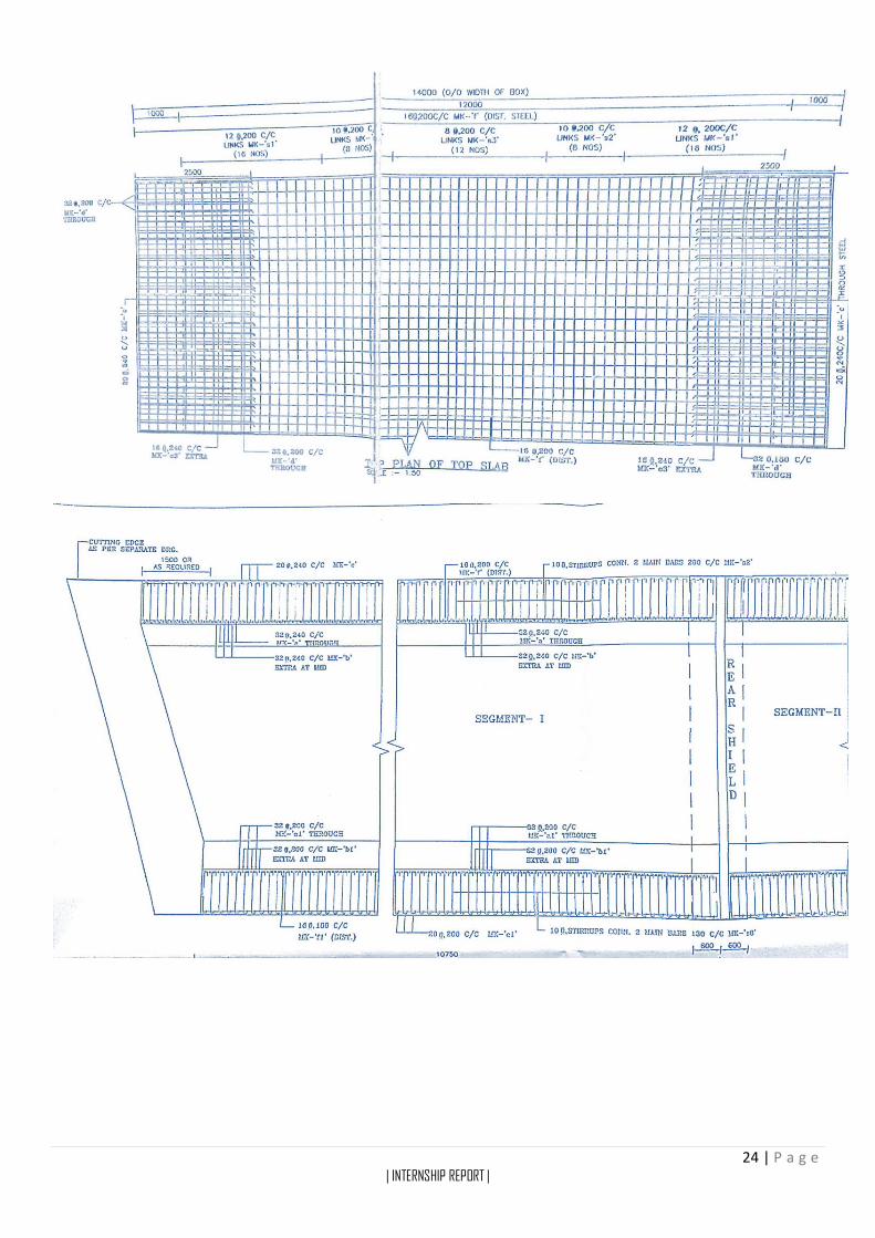
24 | P a g e | INTERNSHIP REPORT |
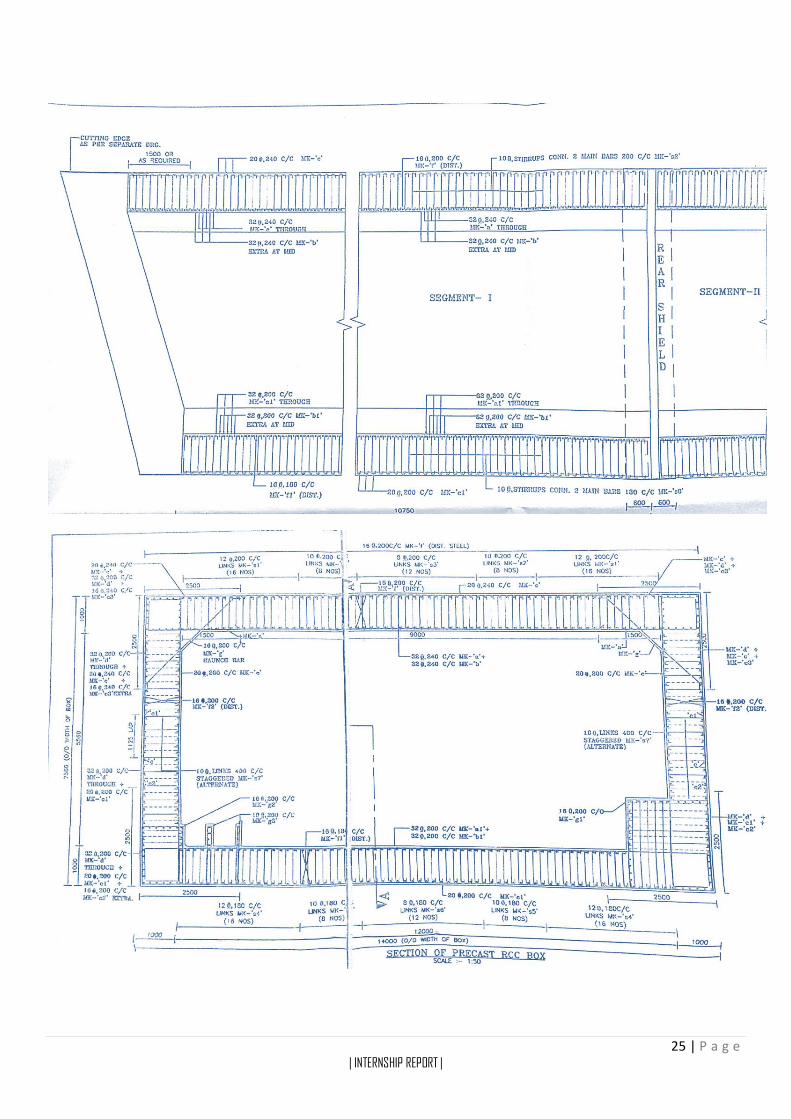
25 | P a g e | INTERNSHIP REPORT |
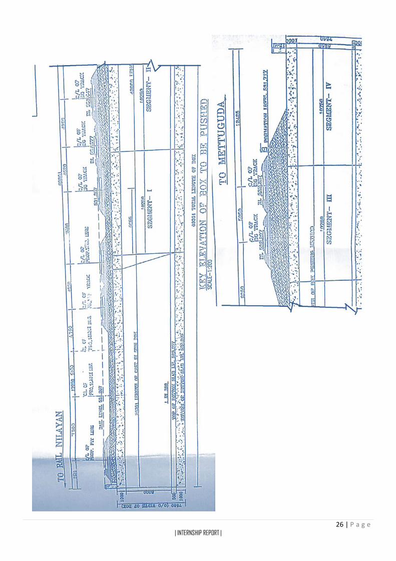
26 | P a g e | INTERNSHIP REPORT |
27 | P a g e | INTERNSHIP REPORT |
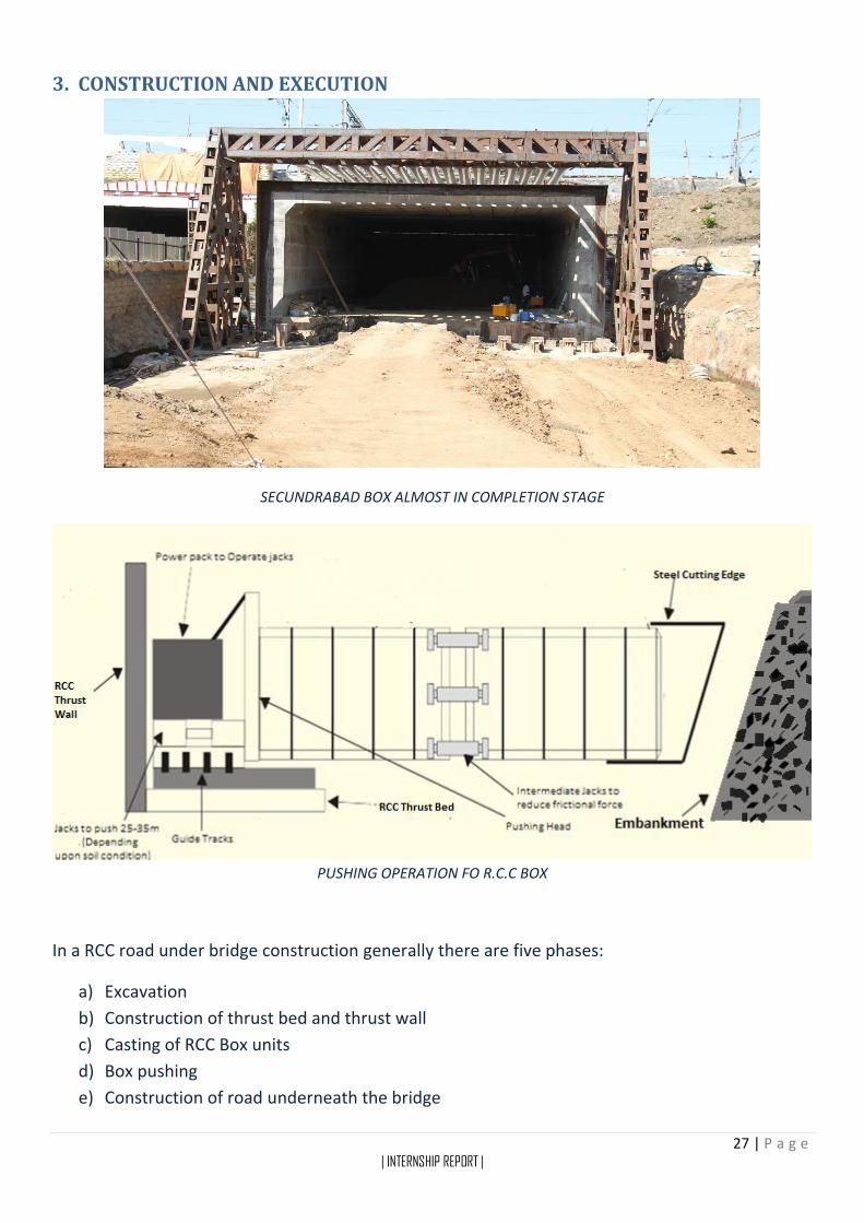
3. CONSTRUCTION AND EXECUTION
SECUNDRABAD BOX ALMOST IN COMPLETION STAGE
PUSHING OPERATION FO R.C.C BOX
In a RCC road under bridge construction generally there are five phases:
a) Excavation
b) Construction of thrust bed and thrust wall
c) Casting of RCC Box units
d) Box pushing
e) Construction of road underneath the bridge
28 | P a g e | INTERNSHIP REPORT |
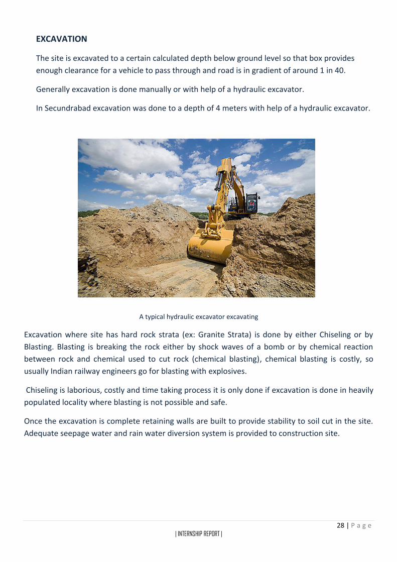
EXCAVATION
The site is excavated to a certain calculated depth below ground level so that box provides
enough clearance for a vehicle to pass through and road is in gradient of around 1 in 40.
Generally excavation is done manually or with help of a hydraulic excavator.
In Secundrabad excavation was done to a depth of 4 meters with help of a hydraulic excavator.
A typical hydraulic excavator excavating
Excavation where site has hard rock strata (ex: Granite Strata) is done by either Chiseling or by
Blasting. Blasting is breaking the rock either by shock waves of a bomb or by chemical reaction
between rock and chemical used to cut rock (chemical blasting), chemical blasting is costly, so
usually Indian railway engineers go for blasting with explosives.
Chiseling is laborious, costly and time taking process it is only done if excavation is done in heavily
populated locality where blasting is not possible and safe.
Once the excavation is complete retaining walls are built to provide stability to soil cut in the site.
Adequate seepage water and rain water diversion system is provided to construction site.
29 | P a g e | INTERNSHIP REPORT |
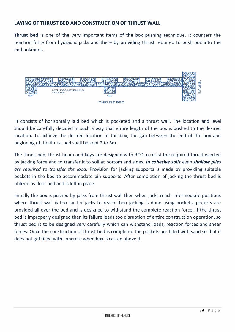
LAYING OF THRUST BED AND CONSTRUCTION OF THRUST WALL
Thrust bed is one of the very important items of the box pushing technique. It counters the
reaction force from hydraulic jacks and there by providing thrust required to push box into the
embankment.
It consists of horizontally laid bed which is pocketed and a thrust wall. The location and level
should be carefully decided in such a way that entire length of the box is pushed to the desired
location. To achieve the desired location of the box, the gap between the end of the box and
beginning of the thrust bed shall be kept 2 to 3m.
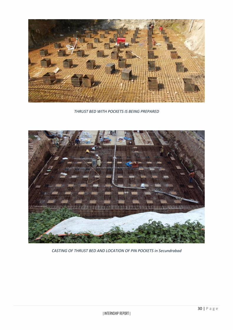
The thrust bed, thrust beam and keys are designed with RCC to resist the required thrust exerted
by jacking force and to transfer it to soil at bottom and sides. In cohesive soils even shallow piles
are required to transfer the load. Provision for jacking supports is made by providing suitable
pockets in the bed to accommodate pin supports. After completion of jacking the thrust bed is
utilized as floor bed and is left in place.
Initially the box is pushed by jacks from thrust wall then when jacks reach intermediate positions
where thrust wall is too far for jacks to reach then jacking is done using pockets, pockets are
provided all over the bed and is designed to withstand the complete reaction force. If the thrust
bed is improperly designed then its failure leads too disruption of entire construction operation, so
thrust bed is to be designed very carefully which can withstand loads, reaction forces and shear
forces. Once the construction of thrust bed is completed the pockets are filled with sand so that it
does not get filled with concrete when box is casted above it.
30 | P a g e | INTERNSHIP REPORT |
THRUST BED WITH POCKETS IS BEING PREPARED
CASTING OF THRUST BED AND LOCATION OF PIN POCKETS in Secundrabad
31 | P a g e | INTERNSHIP REPORT |
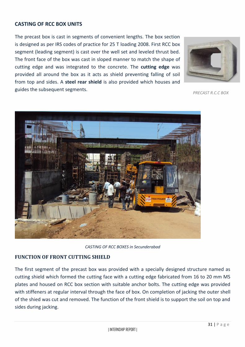
CASTING OF RCC BOX UNITS
The precast box is cast in segments of convenient lengths. The box section
is designed as per IRS codes of practice for 25 T loading 2008. First RCC box
segment (leading segment) is cast over the well set and leveled thrust bed.
The front face of the box was cast in sloped manner to match the shape of
cutting edge and was integrated to the concrete. The cutting edge was
provided all around the box as it acts as shield preventing falling of soil
from top and sides. A steel rear shield is also provided which houses and
guides the subsequent segments.
CASTING OF RCC BOXES in Secunderabad
FUNCTION OF FRONT CUTTING SHIELD
The first segment of the precast box was provided with a specially designed structure named as
cutting shield which formed the cutting face with a cutting edge fabricated from 16 to 20 mm MS
plates and housed on RCC box section with suitable anchor bolts. The cutting edge was provided
with stiffeners at regular interval through the face of box. On completion of jacking the outer shell
of the shied was cut and removed. The function of the front shield is to support the soil on top and
sides during jacking.
PRECAST R.C.C BOX

32 | P a g e | INTERNSHIP REPORT |
FUNCTION OF REAR JACKING SHIELD
The rear jacking shield was provided by anchoring steel plate on the face of
the bottom slab of RCC box suitably designed to distribute the jacking load
uniformly on concrete area. The function of rear shield is to house and
guide the following segments. It also functions as a hood for supporting the
soil on top and sides between the two units.
INTERMEDIATE JACKING STATION
As total length of box is cast in segments, each segment is pushed turn by turn with necessary
jacking force. Necessary intermediate jacking stations are provided with jacking pockets in bed &
walls.
COUPLING
Coupling units, this mechanism is provided to join two segments of Boxes
A TYPICAL BOX IS BEING CASTED, THE COUPLING UNIT IS CLEARLY SEEN
CUTTING SHEILD

33 | P a g e | INTERNSHIP REPORT |
PUSHING OPERATION OF THE BOX
To reduce the frictional resistance, a thin film of grease and
thick gauge plastic sheets are provided between the top of
the thrust bed & bottom of the box. This is done before
casting of the bottom slab of the box. A glossy epoxy layer
is also provided to reduce friction on the top and prevent
the distribution to the earth and ballast mass over box
during pushing operation. Average rate of pushing is
maximum 1 meter in 24 hours to ensure safety.
DRAG SHEET ARRANGEMENT OVER BOX in Secunderabad
ARRANGEMENT OF A WORKING PIN IN POCKET

34 | P a g e | INTERNSHIP REPORT |
Where mass of embankment is less or the soil is of poor quality drag sheet system is also
considered for least resistance of friction and disturbance to the mass above box.
Auxiliary beds are also provided for casting of the other segments with thin film of grease and
plastic. Segments are then brought in alignment of pushing as and when required as pushing
progresses. With the progress of jacking, the front unit with shield penetrates into the
embankment. There after excavation within the shield is done either manually or mechanically and
the excavated stuff is transported outside the working area.
The progress of pushing is kept continuous and the system of shifting of remaining box segments
from auxiliary bed and bringing them into alignment is adopted till total length is pushed.
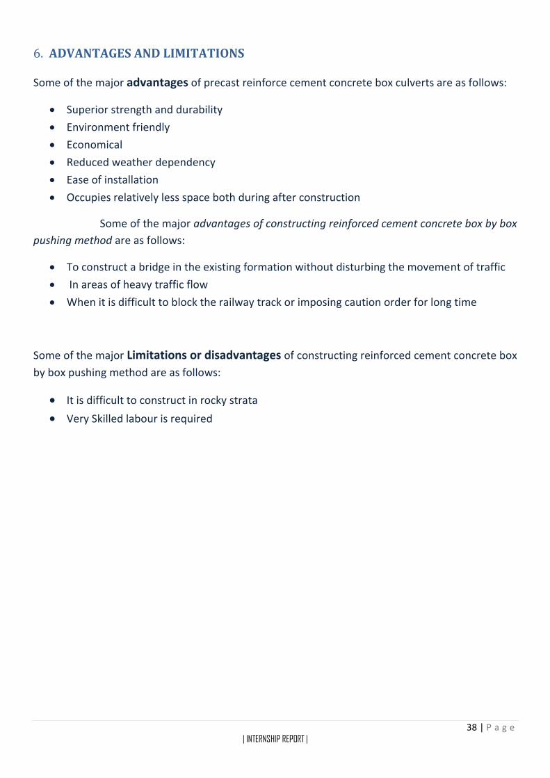
HYDRAULIC EQUIPMENT
Sufficient numbers of Jack units are provided in series for distribution of pushing load evenly on
the face of the concrete, and all jacks are operated simultaneously with a common power pack,
which supplies uniform flow of pressure through network of hydraulic pipes commencing from
front unit to rear unit. Jacking force is applied in sequence. The pushing cycles are repeated till
total pushing is completed.
TYPICAL HYDRAULIC EQUIPMENT PUSHING BOX USING INTERMEDIATE POCKET AS SUPPORT
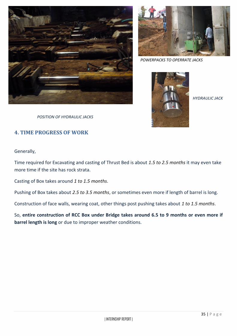
35 | P a g e | INTERNSHIP REPORT |
POWERPACKS TO OPERRATE JACKS
HYDRAULIC JACK
POSITION OF HYDRAULIC JACKS
4. TIME PROGRESS OF WORK
Generally,
Time required for Excavating and casting of Thrust Bed is about 1.5 to 2.5 months it may even take
more time if the site has rock strata.
Casting of Box takes around 1 to 1.5 months.
Pushing of Box takes about 2.5 to 3.5 months, or sometimes even more if length of barrel is long.
Construction of face walls, wearing coat, other things post pushing takes about 1 to 1.5 months.
So, entire construction of RCC Box under Bridge takes around 6.5 to 9 months or even more if
barrel length is long or due to improper weather conditions.

36 | P a g e | INTERNSHIP REPORT |
KEY PLAN

37 | P a g e | INTERNSHIP REPORT |
5. SAFTEY AND PRECAUTIONARY MEASURES
Cutting edge of front shield is fabricated with adequate thickness of steel plate and the
front edges of the steel plate are sharpened to facilitate penetration into the soil.
Cutting edge shall be projected more at the top with respect to bottom slab to prevent
falling of earth from top during excavation.
Leading segment shall be pushed at least 10cm less than the length of the rear shield in one
operation.
To prevent caving of earth during excavation quantity of earth shall be removed to barest
minimum duly following the slop of cutting edge.
Guide channels to be provided in the thrust bed to guide the segments to ensure straight
alignment.
Support is provided under the rail sleepers so that if the cushion under ballast collapses
suddenly due to loose soil or coaly soil present under earth cushion collapses suddenly
while pushing the box.
SUPPORT PROVIDED UNDER THE RAILS AND SLEEPERS TO AVOID SUDDEN COLLAPSE DURING PUSHING
Average rate of pushing should not be more than one meter in 24 hours.
Measures should be taken to restrict the passage of trains over the bridge while the work is
carried on.
The concerned personnel must be present in the field during all the operations.
Care must be taken so that the workers don't get hurt during the work.
Rail tracks must be aligned to their original positions under the guidelines of the concerned
officer after the work is completed.
38 | P a g e | INTERNSHIP REPORT |
6. ADVANTAGES AND LIMITATIONS
Some of the major advantages of precast reinforce cement concrete box culverts are as follows:
Superior strength and durability
Environment friendly
Economical
Reduced weather dependency
Ease of installation
Occupies relatively less space both during after construction
Some of the major advantages of constructing reinforced cement concrete box by box
pushing method are as follows:
To construct a bridge in the existing formation without disturbing the movement of traffic
In areas of heavy traffic flow
When it is difficult to block the railway track or imposing caution order for long time
Some of the major Limitations or disadvantages of constructing reinforced cement concrete box
by box pushing method are as follows:
It is difficult to construct in rocky strata
Very Skilled labour is required
39 | P a g e | INTERNSHIP REPORT |
7. REFERENCES
CODES AND REGULATIONS
Indian railway bridge rules
IRS bridge substructure and foundation code
Loading: 25T – 2008 loading
IS 456 – 2000
ONLINE REFERNCES
https://www.wiki.iricen.gov.in
http://www.jainspunpipes.com/precast-concrete-box-colverts.html
www.ravibuilders.com/RCC_Box_Jacking.html
http://iricen.indianrailways.gov.in
www.nemiket.com/Completed.html
Bridge Engineering , Second Edition By S Ponnuswamy
www.wikipedia.com
www.mathalino.com
C. CONCLUSION
The box pushing method adopted for this Level Crossing is found suitable and convenient as per
the site conditions. Number of construction of joints in this method is reduced compare to cut and
cover method. Requirement of Mega Line Block could also be avoided by adopting this technique.
Though the cost of construction in this method is more, it is adopted mainly due to non-availability
of Mega Line Block and due to non-availability of longer temporary girders (R. H. Girders). The box
pushing work has been successfully completed without disturbance to track as Drag Sheet has
facilitated for smooth insertion of Box through formation.
40 | P a g e | INTERNSHIP REPORT |
APPENDICES
INDIAN RAILWAY BRIDGE RULES
2.3.2.1. The live load due to pedestrian traffic shall be treated as uniformly distributed over the
footway. For the design of footbridges or footpaths on railway bridges the live load including
dynamic effects shall be taken as 4.8 kPa (490 kg/m2) of the footpath area. For the design of foot-
path on a road bridge or road rail bridge, the live load including dynamic effects may be taken as
4.07 kPa (415 kg/m2) except that, where crowd loading is likely, this may be increased to 4.8 kPa
(490 kg/m2).
2.3.4.2 Dispersion of railway live loads shall be as follows:
(a) Distribution through sleepers and ballast: The sleeper may be assumed to distribute the live load uniformly on top of the ballast over the area of contact given below:
TYPE 1 TYPE 2
Under each rail seat
BG 2745mm X 254mm 760mm X 330mm
MG 1830mm X 203 mm 610mm X 270mm
2.4 DYNAMIC EFFECT 2.4.1 Railway Bridges (Steel) 2.4.1.1 For Broad and Metre Gauge Railway: The augmentation in load due to dynamic effects should be considered by adding a load Equivalent to a Coefficient of Dynamic Augment (CDA) multiplied by the live load giving the maximum stress in the member under consideration. The CDA should be obtained as follows and shall be applicable upto 160 km/h on BG and 100 km/h on MG – (a) For single track spans:
CDA= 0.15 +8
6+L
Where, L is the loaded length of span in metres for the position of the train giving the maximum
stress in the member under consideration.
41 | P a g e | INTERNSHIP REPORT |
2.4.2 Railway pipe culverts, arch bridges, concrete slabs and concrete girders. 2.4.2.1 For all gauges (a) If the depth of fill is less than 900mm, the Coefficient of Dynamic Augment shall be equal to- [2-(d/0.9)] *CDA/2 as obtained from Clause 2.4.1.1(a) Where, d = depth of fill in ‘m’. (b) If the depth of fill is 900mm, the Coefficient of Dynamic Augment shall be half of that specified in clause 2.4.1.1(a) subject to a maximum of 0.5. Where depth of fill exceeds 900mm, the Coefficient of Dynamic Augment shall be uniformly decreased to zero within the next 3 metres.
(c) In case of concrete girders of span of 25m and larger, the CDA shall be as specified in Clause 2.4.1.1.
APPENDIX - XXIII “25t Loading-2008” BROAD GAUGE-1676 mm Equivalent Uniformly Distributed Loads (EUDL) in kilo Newtons (tonnes) on each track, and Coefficient of Dynamic Augment (CDA). For Bending Moment, L is equal to the effective span in metres. For Shear Force, L is the loaded length in metres to give the maximum Shear Force in the member under consideration. The Equivalent Uniformly Distributed Load (EUDL) for Bending Moment (BM), for spans upto 10m, is that uniformly distributed load which produces the BM at the centre of the span equal to the absolute maximum BM developed under the standard loads. For spans above 10m,
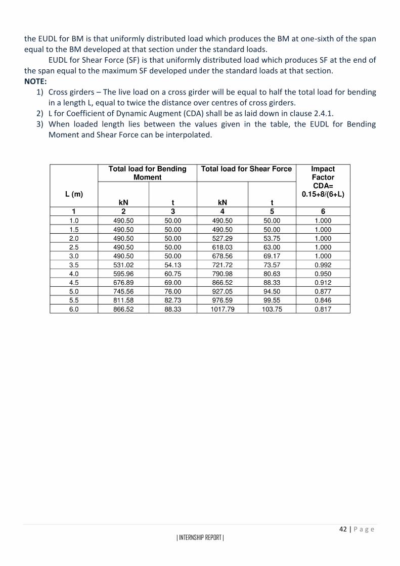
42 | P a g e | INTERNSHIP REPORT |
the EUDL for BM is that uniformly distributed load which produces the BM at one-sixth of the span equal to the BM developed at that section under the standard loads. EUDL for Shear Force (SF) is that uniformly distributed load which produces SF at the end of the span equal to the maximum SF developed under the standard loads at that section. NOTE:
1) Cross girders – The live load on a cross girder will be equal to half the total load for bending in a length L, equal to twice the distance over centres of cross girders.
2) L for Coefficient of Dynamic Augment (CDA) shall be as laid down in clause 2.4.1. 3) When loaded length lies between the values given in the table, the EUDL for Bending
Moment and Shear Force can be interpolated.

43 | P a g e | INTERNSHIP REPORT |
44 | P a g e | INTERNSHIP REPORT |
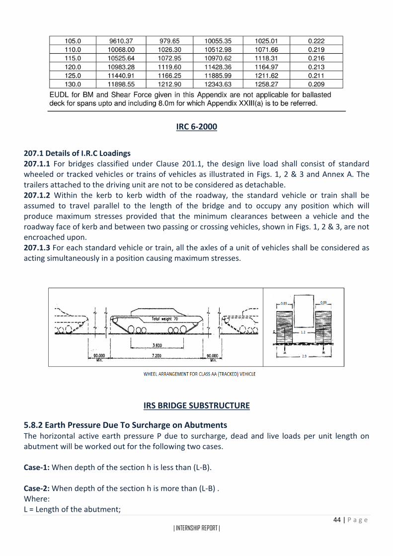
IRC 6-2000
207.1 Details of I.R.C Loadings 207.1.1 For bridges classified under Clause 201.1, the design live load shall consist of standard wheeled or tracked vehicles or trains of vehicles as illustrated in Figs. 1, 2 & 3 and Annex A. The trailers attached to the driving unit are not to be considered as detachable. 207.1.2 Within the kerb to kerb width of the roadway, the standard vehicle or train shall be assumed to travel parallel to the length of the bridge and to occupy any position which will produce maximum stresses provided that the minimum clearances between a vehicle and the roadway face of kerb and between two passing or crossing vehicles, shown in Figs. 1, 2 & 3, are not encroached upon. 207.1.3 For each standard vehicle or train, all the axles of a unit of vehicles shall be considered as acting simultaneously in a position causing maximum stresses.
IRS BRIDGE SUBSTRUCTURE
5.8.2 Earth Pressure Due To Surcharge on Abutments The horizontal active earth pressure P due to surcharge, dead and live loads per unit length on abutment will be worked out for the following two cases. Case-1: When depth of the section h is less than (L-B). Case-2: When depth of the section h is more than (L-B) . Where: L = Length of the abutment;
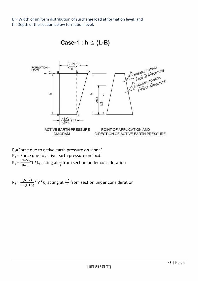
45 | P a g e | INTERNSHIP REPORT |
B = Width of uniform distribution of surcharge load at formation level; and h= Depth of the section below formation level.
P1=Force due to active earth pressure on ‘abde’ P2 = Force due to active earth pressure on ‘bcd.
P1 = (S+V)
B+h*h*ka acting at
h
2 from section under consideration
P2 = (S+V)
2B(B+h)*h2*ka acting at
2h
3 from section under consideration

46 | P a g e | INTERNSHIP REPORT |
P1 = Force due to active earth pressure on ‘’abdefg’’ P2 = Force due to active earth pressure on “bcd”
P1 = (S+V)
L*h*ka acting at
h
2 from section under consideration
P2 = (S+V)
2BL*(L-B) 2*ka acting at [h -
L−B
3] from section under consideration
Where, S = Live load surcharge for unit length. V = Dead load surcharge for unit length. h = Height of fill. This is assumed to act at a height of h/2 from base of the section under consideration. Surcharge due to live load and dead load may be assumed to extend upto the front face of the ballast wall.
47 | P a g e | INTERNSHIP REPORT |
ABOUT FEW OTHER R.U.B. BOX SITES VISITED
I. BOX PUSHING IN RAICHUR (Karnataka, India)
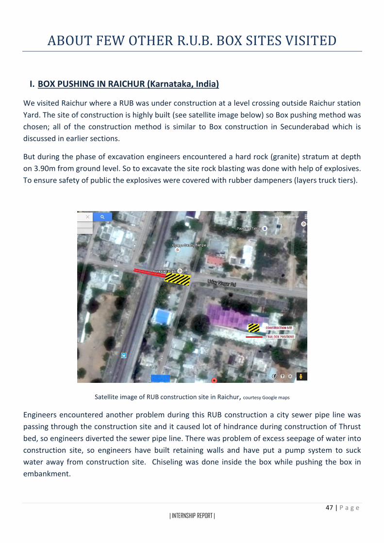
We visited Raichur where a RUB was under construction at a level crossing outside Raichur station
Yard. The site of construction is highly built (see satellite image below) so Box pushing method was
chosen; all of the construction method is similar to Box construction in Secunderabad which is
discussed in earlier sections.
But during the phase of excavation engineers encountered a hard rock (granite) stratum at depth
on 3.90m from ground level. So to excavate the site rock blasting was done with help of explosives.
To ensure safety of public the explosives were covered with rubber dampeners (layers truck tiers).
Satellite image of RUB construction site in Raichur, courtesy Google maps
Engineers encountered another problem during this RUB construction a city sewer pipe line was
passing through the construction site and it caused lot of hindrance during construction of Thrust
bed, so engineers diverted the sewer pipe line. There was problem of excess seepage of water into
construction site, so engineers have built retaining walls and have put a pump system to suck
water away from construction site. Chiseling was done inside the box while pushing the box in
embankment.

48 | P a g e | INTERNSHIP REPORT |
Pictures of RUB Box construction site in Raichur
49 | P a g e | INTERNSHIP REPORT |
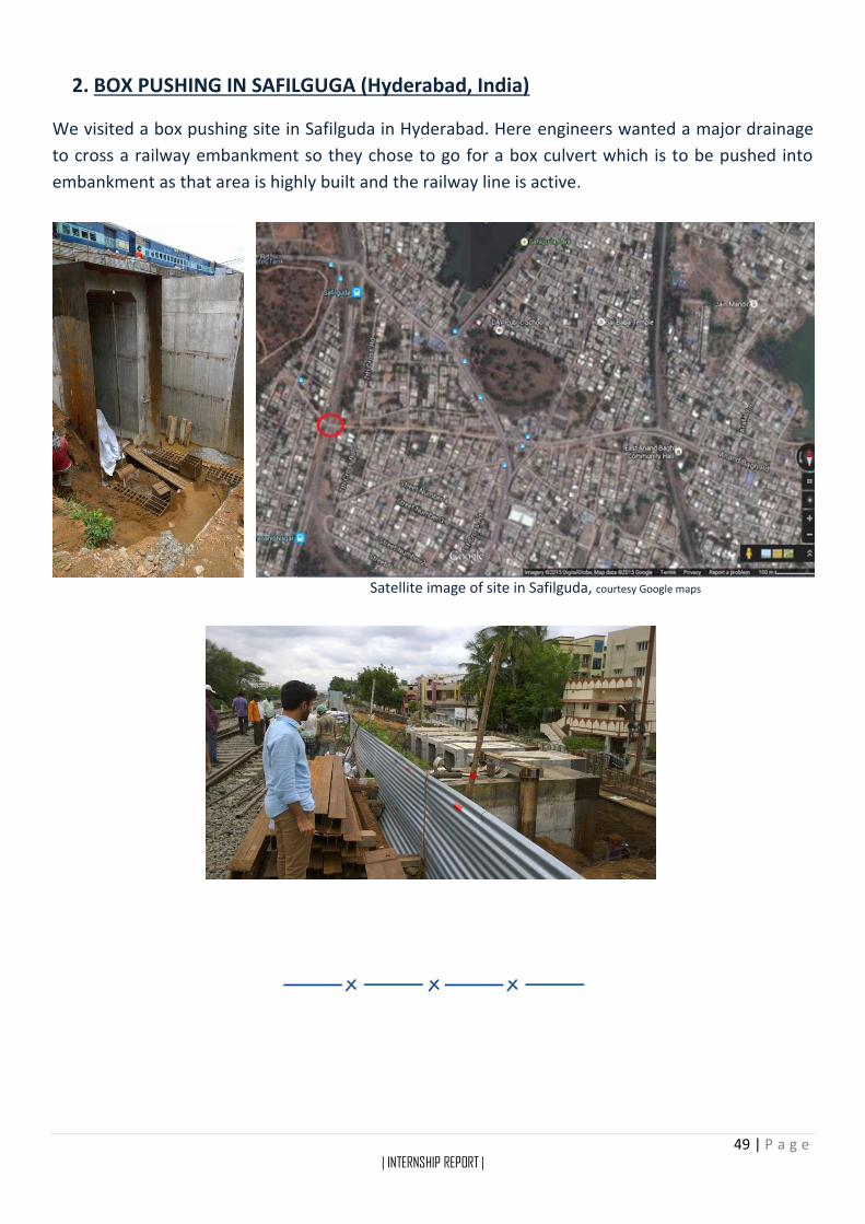
2. BOX PUSHING IN SAFILGUGA (Hyderabad, India)
We visited a box pushing site in Safilguda in Hyderabad. Here engineers wanted a major drainage
to cross a railway embankment so they chose to go for a box culvert which is to be pushed into
embankment as that area is highly built and the railway line is active.
Satellite image of site in Safilguda, courtesy Google maps
Related Documents