
Registers & Counters M. Önder Efe [email protected].
Dec 27, 2015
Welcome message from author
This document is posted to help you gain knowledge. Please leave a comment to let me know what you think about it! Share it to your friends and learn new things together.
Transcript


Registers• Registers are clocked sequential circuits• A register is a group of flip-flops– Each flip-flop capable of storing one bit of information– An n-bit register • consists of n flip-flops• capable of storing n bits of information
– besides flip-flops, a register usually contains combinational logic to perform some simple tasks
– In summary• flip-flops to hold information• combinational logic to control the state transition

Counters• A counter is essentially a register that goes through a predetermined
sequence of states• “Counting sequence”
RegisterFF0 FF1 FFn-1
Combinational logic

Uses of Registers and Counters• Registers are useful for storing and manipulating
information– internal registers in microprocessors to manipulate data
• Counters are extensively used in control logic– PC (program counter) in microprocessors

4-bit Register (Parallel)
REG
Q3
Q2
Q1
Q0
D3
D2
D1
D0
clear
D Q
clock
CR
D Q
CR
D Q
CR
D Q
CR
clear
D0
D1
D2
D3
Q0
Q1
Q2
Q3

4-bit Register (Parallel)module parallel_reg(Q3,Q2,Q1,Q0,D3,D2,D1,D0,clock,clear);output Q3,Q2,Q1,Q0;input D3,D2,D1,D0,clock,clear;reg Q3,Q2,Q1,Q0;
always @(posedge clock or negedge clear) if(~clear) {Q3,Q2,Q1,Q0}<=4'b0000; else begin Q3 <= D3; Q2 <= D2; Q1 <= D1; Q0 <= D0; endendmodule

Register with Parallel LoadLoad
D Q
CR
Q0
D Q
CR
Q1
D Q
CR
Q2
D Q
CR
Q3
clockclear
D1
D2
D3
D0

4-bit Parallel Register with Load module parallel_reg(Q3,Q2,Q1,Q0,D3,D2,D1,D0,clock,clear,Load);output Q3,Q2,Q1,Q0;input D3,D2,D1,D0,clock,clear,Load;reg Q3,Q2,Q1,Q0;always @(posedge clock or negedge clear) if(~clear) {Q3,Q2,Q1,Q0}<=4'b0000; else
if(Load) begin Q3 <= D3; Q2 <= D2; Q1 <= D1; Q0 <= D0; endendmodule

Shift Registers• A register capable of shifting its content in one or
both directions – Flip-flops in cascade
serial input
serial outputD Q
C
SID Q
C
D Q
C
D Q
C
SO
clock
• The current of n-bit shift register state can be transferred in n clock cycles
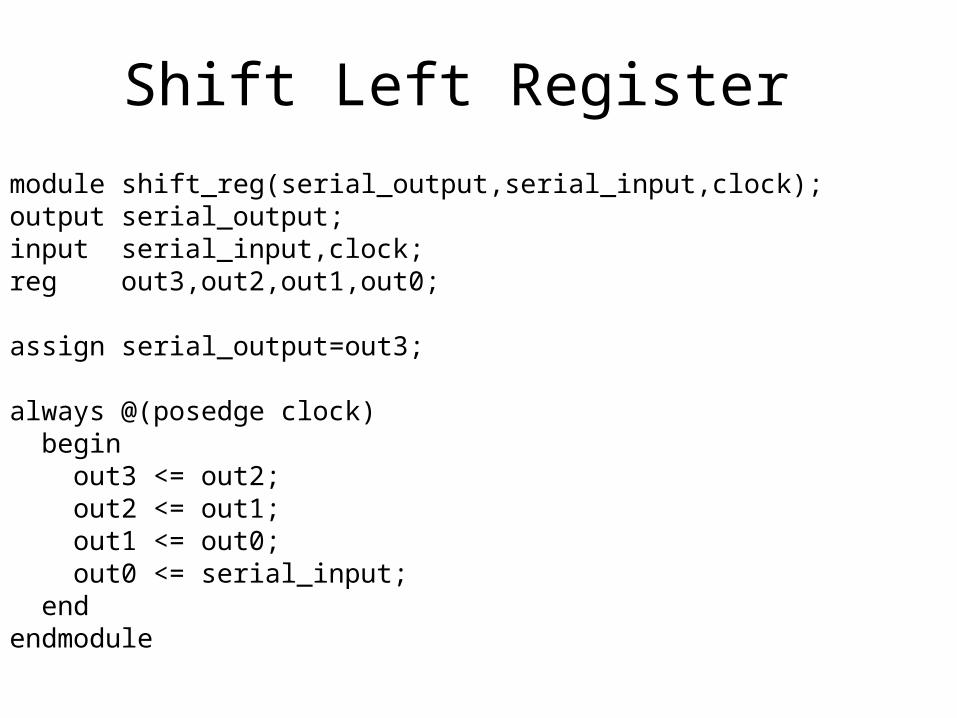
Shift Left Registermodule shift_reg(serial_output,serial_input,clock);output serial_output;input serial_input,clock;reg out3,out2,out1,out0; assign serial_output=out3; always @(posedge clock) begin out3 <= out2; out2 <= out1; out1 <= out0; out0 <= serial_input; endendmodule

Universal Shift Register
• Capabilities:1. A “clear” control to set the register to 0.2. A “clock” input3. A “shift-right” control4. A “shift-left” control5. n input lines & a “parallel-load” control6. n parallel output lines

Universal Shift Register
Mode Control
Register operations1 s0
0 0 No change
0 1 Shift right
1 0 Shift left
1 1 Parallel load
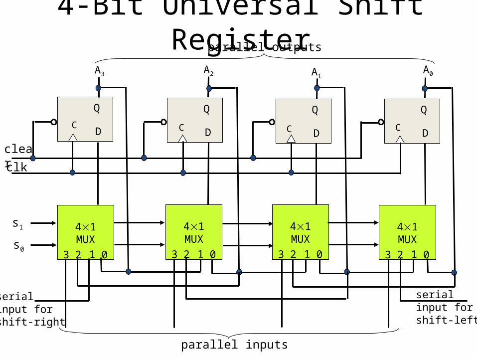
4-Bit Universal Shift Register
D
Q
CD
Q
CD
Q
CD
Q
C
A0A1A2A3
parallel outputs
clear
clk
41MUX
0123
41MUX
0123
41MUX
0123
41MUX
0123
s1
s0
serialinput for shift-right
serial input for shift-left
parallel inputs

Verilog Code – v1// Behavioral description of a 4-bit universal shift registermodule Shift_Register_4_beh ( // V2001, 2005output reg [3: 0] O_par, // Register outputinput [3: 0] I_par, // Parallel inputinput s1, s0, // Select inputsMSB_in, LSB_in, // Serial inputsCLK, // Clock Clear); // Clearalways @ ( posedge CLK, negedge Clear) // V2001, 2005
if (Clear== 0) O_par <= 4'b0000;
elsecase ({s1, s0})
2'b00: O_par <= O_par; // No change2'b01: O_par <= {MSB_in, O_par[3: 1]}; // Shift right2'b10: O_par <= {O_par[2: 0], LSB_in}; // Shift left2'b11: O_par <= I_par; // Parallel load of input
endcaseendmodule

Verilog Code – v2// Behavioral description of a 4-bit universal shift registermodule Shift_Register_4_beh ( // V2001, 2005output reg [3: 0] O_par, // Register outputinput [3: 0] I_par, // Parallel inputinput s1, s0, // Select inputsMSB_in, LSB_in, // Serial inputsCLK, // Clock Clear); // Clearalways @ ( posedge CLK, negedge Clear) // V2001, 2005
if (Clear== 0) O_par <= 4'b0000;
elsecase ({s1, s0})
// 2'b00: O_par <= O_par; // No change2'b01: O_par <= {MSB_in, O_par[3: 1]}; // Shift right2'b10: O_par <= {O_par[2: 0], LSB_in}; // Shift left2'b11: O_par <= I_par; // Parallel load of input
endcaseendmodule

D Q D Q D Q D QIN
OUT1 OUT2 OUT3 OUT4
CLK
OUT
Pattern Recognizer
• Combinational function of input samples– In this case, recognizing the pattern 1001 on the
single input signal
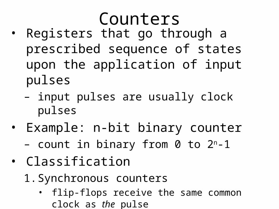
Counters• Registers that go through a prescribed sequence
of states upon the application of input pulses– input pulses are usually clock pulses
• Example: n-bit binary counter– count in binary from 0 to 2n-1
• Classification1. Synchronous counters• flip-flops receive the same common clock as the pulse
2. Ripple counters (Asynchronous)• flip-flop output transition serves as the pulse to trigger
other flip-flops

Binary Ripple Counter
0 0 0 0
1 0 0 1
2 0 1 0
3 0 1 1
4 1 0 0
5 1 0 1
6 1 1 0
7 1 1 1
0 0 0 0
3-bit binary ripple counter
• Idea:– to connect the output of one flip-flop to
the C input of the next high-order flip-flop
• We need “complementing” flip-flops– We can use T flip-flops to obtain
complementing flip-flops or– JK flip-flops with its inputs are tied
together or– D flip-flops with complement output
connected to the D input.

4-bit Binary Ripple CounterT Q
CR
A0
T Q
CR
A1
T Q
CR
A2
T Q
CR
A3
clear
count
logic-1
D Q
CR
A0
D Q
CR
A1
D Q
CR
A2
D Q
CR
A3
clear
count0 0 0 0 0
1 0 0 0 1
2 0 0 1 0
3 0 0 1 1
4 0 1 0 0
5 0 1 0 1
6 0 1 1 0
7 0 1 1 1
8 1 0 0 0
9 1 0 0 1
10 1 0 1 0
11 1 0 1 1
12 1 1 0 0
13 1 1 0 1
14 1 1 1 0
15 1 1 1 1
0 0 0 0 0
Discouraged
• Know it exists
• Don’t use it

4-bit Binary Ripple CounterT Q
CR
A0
T Q
CR
A1
T Q
CR
A2
T Q
CR
A3
clear
count
logic-1

D Q D Q D Q D Q
OUT1 OUT2 OUT3 OUT4
CLK
"1"
4-bit Binary Synchronous Counter• Logic between registers (not just multiplexer)– XOR decides when bit should be toggled– Always for low-order bit, only when first bit is true
for second bit, and so on
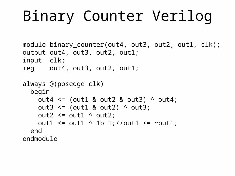
Binary Counter Verilog
module binary_counter(out4, out3, out2, out1, clk);output out4, out3, out2, out1;input clk;reg out4, out3, out2, out1;
always @(posedge clk) begin out4 <= (out1 & out2 & out3) ^ out4; out3 <= (out1 & out2) ^ out3; out2 <= out1 ^ out2; out1 <= out1 ^ 1b'1;//out1 <= ~out1; endendmodule

Binary Counter Verilog
module binary_counter(out, clk);output [3:0] out;input clk;reg [3:0] out;
always @(posedge clk) out <= out + 1; endmodule

Synchronous Counters• There is a common clock– that triggers all flip-flops simultaneously– If T = 0 or J = K = 0 the flip-flop
does not change state.– If T = 1 or J = K = 1 the flip-flop
does change state.• Design procedure is so simple– no need for going through sequential
logic design process– A0 is always complemented
– A1 is complemented when A0 = 1
– A2 is complemented when A0 = 1 and A1 = 1 – so on
0 0 0 0
1 0 0 1
2 0 1 0
3 0 1 1
4 1 0 0
5 1 0 1
6 1 1 0
7 1 1 1
0 0 0 0

4-bit Binary Synchronous CounterJ Q
CA0
J QC
A1
J QC
A2
J QC
A3
K
K
K
K
clock
Count_enable
to next stage

Other Counters• Ring Counter– A ring counter is a circular shift register with only one
flip-flop being set at any particular time, all others are cleared.
shift right Q3 Q2 Q1 Qo
initial value1000
• Usage– Timing signals control the sequence of operations in a digital system
In this case, 1000, 0100, 0010, 0001If one of the patterns is its initial state (by loading or set/reset)

Ring Counter• Sequence of timing signals
clock
Q3
Q2
Q1
Q0
Ring Counter
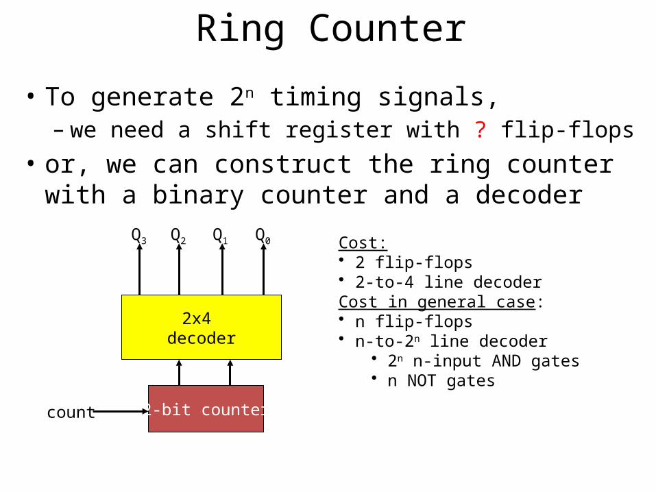
• To generate 2n timing signals, – we need a shift register with ? flip-flops
• or, we can construct the ring counter with a binary counter and a decoder
2x4 decoder
Q3 Q2 Q1 Q0
2-bit countercount
Cost:• 2 flip-flops• 2-to-4 line decoderCost in general case: • n flip-flops• n-to-2n line decoder
• 2n n-input AND gates• n NOT gates

Ring Counter Verilogmodule ring_counter(Q,Clock,Resetn);input Clock,Resetn;output [3:0] Q;reg [3:0] Q;
always @(posedge Clock or negedge Resetn) if(!Resetn) Q <= 4'b1000; else Q <= {Q[0],Q[3:1]};
//Q[3]<=Q[0];
//Q[2]<=Q[3];
//Q[1]<=Q[2];
//Q[0]<=Q[1];endmodule

Johnson Counter• A k-bit ring counter can generate k
distinguishable states• The number of states can be doubled if the shift
register is connected as a switch-tail ring counter
clock
D Q
C
D Q
C
D Q
C
D Q
C
X
X’
Y
Y’
Z
Z’
T
T’
In this case, 0000, 1000, 1100, 1110, 1111, 0111, 0011, 0001

Johnson Counter Verilog
module johnson_counter(X,Y,Z,T,clock,Resetn);input clock,Resetn;output X,Y,Z,T;reg X,Y,Z,T;
always @(posedge clock or negedge Resetn) if(!Resetn) {X,Y,Z,T} <= 4'b0000; else X <= ~T;
Y <= X;
Z <= Y;
T <= Z;
endmodule

Rising Edge Detector ("0" to "1" transition)
Verilog Kodu?

Falling Edge Detector ("1" to "0" transition)
Verilog Kodu?

Edge Detector(Rising or Falling Edge Detector)
("1" to "0" or "0" to "1" transition)
?
Related Documents


