Multi-touch Meter / Analyser EN Refs. 596101, 596111 User manual www.televes.com

Welcome message from author
This document is posted to help you gain knowledge. Please leave a comment to let me know what you think about it! Share it to your friends and learn new things together.
Transcript

Multi-touch Meter / AnalyserEN
Refs. 596101, 596111
User manual
www . t e l e v e s . c o m


EN
GLI
SH
EN
Index
Safety requirements 4Symbols and safety labels 4
Introducing the MOSAIQ6 5Key features 5General Specifications 6Technical Specifications 7Description of equipment components 9
Connectors and controls 9
Keyboard 9Power supply 10
About the battery 10
Separately battery charge 11Gestures 12Before starting 12Icons on the screen 14
Bottom bar: 14
Top bar: 15Menus 16
Top Menu 16
Main Menu 16
Options context menu 16Top menu 16
Inputs/Outputs: 16
Powering: 17
Settings: 17Main menu 19
1. Settings 19
2. User profiles 21
3. Optical attenuation 23
4. Satellite identification 24
5. LTE check 25
6. TV Analyser 26
7. Spectrum analyser 42
8. Radio Analyser 44
9. Wi-Fi Analyser 48
10. Network Tools 51
11. Drive Test 53
13. LOGS 55Web application 57
1.- Measurements 57
2. Plans 58
3. SCR 60
4. Quality profiles 60
5. User profiles 61
6. Antenna profile 61
7. Clone 61
8. Licenses 62
9. Remote control 62
10. Configuration 62MOSAIQ6 Cloud 63
Error messages 64
Technical support 65Warranty 65

MOSAIQ6 Multi-touch Meter/Analyser4
Servicing- There are no user serviceable parts except the battery pack. Do not attempt to service this product or remove covers. Refer all servicing to qualified service personnel. Follow the instructions in this manual when replacing the battery.
Heat
- The product should be situated away from heat sources such as radiators, heat registers, stoves, or other products that produce heat..
- Do not place naked flame sources on the meter, such as lighted candles.
Battery pack - Battery must be replaced by the battery pack
supplied by the manufacturer (ref. 596210) only. In no case the battery pack cover can be opened.
- This product should be operated only from the type of power source specified (12VDC - 4A).
- Ensure that the voltage applied to the power connector does not exceed 15V. Higher voltages could damage the equipment
- May explode if damaged or disposed of in fire or water
Class - Operation of this equipment in a residential
environment may cause radio interference.
Symbols and safety labels
Recycle or dispose of used electronic devices properly.
The equipment contains a recyclable battery. Before depositing the equipment in the container of electrical and electronic equipment, you must remove the battery pack and deposit it separately for proper management
Battery can only be replaced by the battery pack supplied by the manufacturer (ref. 596210)
Input power / Alimentación: 12V ; 2A, 24W
0916
Ref. 593304
Recycle or dispose of used electrical andelectronic devices properly.
H30Flex
100% Designed, Developed, andManufactured by Televes Corporation
Replace the batteries only with the same type. Reemplace las baterías sólo por el tiporecomendado.
Deposite los residuos de aparatos eléctricos yelectrónicos en los contenedores al efecto.
S.N.- 09169999900011
Made in Spain
DVB-S/S2 + DVB-T/T2 + DVB-CA00383
Connector / Conector: P1J
Sample. Not for sale
Safety requirements
Product inspection - Inspect the equipment for shipping damage.
Should any damage be discovered, immediately file a claim with the carrier.
Read and Follow All Instructions - All the safety and operating instructions should
be read prior to and followed while operating this product.
Do not obstruct the ventilation slots
Cleaning - Follow the cleaning instructions contained in
the Maintenance section of this manual. Attachments
- Do not use attachments that are not approved by the product manufacturer
Water and Moisture - This product is splash water resistant but is not
submersible.- Do not place objects filled with liquids on or near the meter, such as glasses. Power Sources
- This product should be operated only from the type of power source specified (12VDC - 4A).
-Ensure that the voltage applied to the power connector does not exceed 15V. Higher voltages could damage the equipment- Maximum consumed current: 4A Grounding or Polarization
- Do not bypass or defeat electrical plug polarization or grounding. Doing so will violate the warranty and may pose a risk of fire or electrocution.
Wire Protection- Ensure all connected wiring is routed correctly to avoid damage including pinching, excessive bends, or compression.
Electrical Supply, Grounding, and Surge Protection
- Ensure that all local or national electrical codes are followed.
Power Lines - Always use caution and avoid operating this
or any connected equipment near uninsulated power lines or any other hazards.

EN
5
Overview
Introducing the MOSAIQ6
MOSAIQ6 is the new high-performance portable meter, with advanced features and high measurement accuracy. And all in the most automatic and intuitive way in the market, thanks to its intuitive interface and gestural commands.
With MOSAIQ6, technicians have a tool to measure, analyse and diagnose radio and TV signals in any scenario, no matter how complex.
MOSAIQ6 has an ultra-fast spectrum analyser with high accuracy, together with the echoes analysis features, allows to detect any important issue of the signal.
Key features
High performance portable meter
Intuitive. Thanks to its novel interface, designed to get the most out of its multi-touch 8” screen.
All the information about the signal in one screen. Mosaiq feature, with up to 6 widgets configurable by the user.
Powerful digital spectrum analyser (scanning < 10ms.) 5MHz - 3.3GHz range.
Easily updateable
Spectrum analyser with selectable span
Specific measurements over IP (TSoIP)
PASS/FAIL indicators: Icons indicate if a measurement is good, bad or in the warning zone for quick and easy status check. Reduce installer entry errors and improve decision making.
Field-swappable and separately rechargeable battery
User profiles customization
Automatic channel scan
Automatic satellite identification
GPS for drive test and automatic saving of measurements
LTE interferences detection and simulation

MOSAIQ6 Multi-touch Meter/Analyser6
General Specifications
Display 8” Touch Screen TFT 1024x768 Full Colour
Weight 2150g
Dimensions 250x210x60 mm (H x W x D)
Power supply Input: 100-240V~ 50-60HzOutput: 24VDC, 4A
Battery Li-ion (7,2VDC, 9000mAh). Field-swappable
Operating time > 4 hours
Operating temperature -5ºC to 45ºC (23ºF to 104ºF)
Storage temperature -20ºC to 70ºC (-4ºF to 158ºF )
Humidity 5% to 95% without condensation
Interfaces ETH, USB, HDMI, Audio Out (Jack), FC/APC optical fibre connector, GPS antenna connector
Storage 32 Gb

EN
7
FrequencyRange 5 - 3300 MHzAccuracy 1 kHzTuning Frequency or channelInputImpedance 75 OhmSpectrum Analyzer
Span100 KHz, 1, 5, 10, 20, 50, 100, 200, 500 MHz, 1.0, 2.0 and 3.3 GHz. Other (any value between 100 KHz and 3.3 GHz)
RBW 500 Hz, 1, 3, 5, 10, 30, 50, 100, 300, 500 KHz, 1, 3, 5 MHz
Marks Up to 6, with delta featureRelative marksEvent triggerWaterfallHold feature Maximum and minimumReference level Automatic and manualDigital measurements DVB-TModulations COFDM (QPSK, 16QAM, 64QAM)Power 20 - 128dBuVCBER 1.0E-2 - 1.0E-6VBER 1.0E-2 - 1.0E-8MER Up to 40dBC/N Up to 52dBEchoesMER by carrierConstellationUncorrected packetsTILTAttenuationDigital measurements DVB-T2Modulations COFDM (QPSK, 16QAM, 64QAM and 256QAM)Power 20 - 128dBµVLDPCBER 1.0E-2 - 1.0E-6 (Pre LDPCBER)BCHBER 1.0E-2 - 1.0E-8 (Pre BCHBER or Post LDPCBER)Link Margin Up to 30dBMER Up to 40dBC/N Up to 52dBEchoesMER by carrierConstellationUncorrected packetsTILT
AttenuationMultiple PLPDigital measurements QAM (Annex A/B/C)Modulations 4QAM, 16QAM, 32QAM, 64QAM and 256QAMPower 20 - 128dBµVPre-BER 1.0E-2 – 1.0E-8Post-BER 1.0E-2 – 1.0E-9MER Up to 40dBC/N Up to 52dBConstellationUncorrected packetsTILTAttenuationDigital measurements ISDB-T/TbModulations DQPSK, QPSK, 16QAM and 64QAMPower -100 dBm to 20 dBmC/N Up to 50 dBMER Up to 40dBPre-BER (by layer) 1.0E-2 – 1.0E-6Post-BER (by layer) 1.0E-2 – 1.0E-8EchoesConstellationUncorrected packetsTILTAttenuation
Digital measurements DVB-SWideband(only compatible HW) 250-2400 MHz
Power 20 - 128dBµVCBER 1.0E-2 - 1.0E-6VBER 1.0E-2 - 1.0E-8MER Up to 20dBC/N Up to 30dBConstellationUncorrected packetsTILTAttenuationDigital measurements DVB-S2X Wideband(only compatible HW) 250-2400 MHz
Modulations QPSK, 8PSKPower 20 - 128dBµVLink Margin Up to 10dBMER Up to 20dBC/N Up to 30dB
Specifications are subject to change without notice.
Technical Specifications

MOSAIQ6 Multi-touch Meter/Analyser8
MPEG2, MPEG4 Full HD Channels visualization
4K visualization Option 596205
Info MPEG SID, VID, AID, Resolution, Profile , Audio Bitrate, Video Bitrate, Resolution info
IPTV AnalyzerWifi Analyser 2,4 GHz and 5 GHz (Option 596202)Units dBµV, dBmV, dBmNetwork ToolsPreamp powering
Preamp powering 5,13, 18, 24Vdc and other (any value between 5 and 24V)
Maximum supplied power 12 W
Maximum supplied current 900 mA
LNB Tone 22 KHzDiSEqCSCR | dCSS(EN 50494 | EN 50607)
LDPCBER 1.0E-2 - 1.0E-6 (Pre LDPCBER)BCHBER 1.0E-2 - 1.0E-8 (Pre BCHBER or Post LDPCBER)ConstellationUncorrected packetsTILTAttenuationMulti TSPLS scramblingDigital measurements DVB-S2Wideband(only compatible HW) 250-2400 MHz
Modulations QPSK, 8PSK, 8APSK, 16 APSK & 32 APSKPower 20 - 128dBµVLink Margin Up to 10dBMER Up to 20dBC/N Up to 30dBLDPCBER 1.0E-2 - 1.0E-6 (Pre LDPCBER)BCHBER 1.0E-2 - 1.0E-8 (Pre BCHBER or Post LDPCBER)ConstellationUncorrected packetsTILTAttenuationMulti TSFM MeasurementsLevelC/N Up to 52dBRDSDAB/DAB+ Measurements (Option 596204)Power De 20 - 128 dBµV MER Up to 20 dBC/N Up to 30 dBBER 9.9E-2 – 1.0E-6Analog Measurements (Option 596203)Level 20 - 128dBµVV/A Up to 52dBC/N Up to 30dBFeaturesUp to 6 widgets user-customizableSystem Scan with measurements and learning plan
LTE check (4G/5G)
FO (-40, 7 dBm) Option 596101FO Selective (-40, 7 dBm) Option 596111
GPS Drive Test Option 596201

EN
9
Description of equipment components
Connectors and controls
1. Touch screen 8” 2. Connectors
3. Keyboard and LED indicators 4. Battery (on the back)
1. F.O. 5. CAM 8. HDMI
2. Power connector 6. A/V 9. USB
3. ETHERNET 7. RF Input 10. GPS
4. USB-C (future use)
CAUTION: the USB ports are only for data transmission, not for device
charging
4
13
2
7
5
810
1 2 3
6
4
9
Keyboard
1. Device ON/OFF button: To turn the equipment off, press and hold for approximately 3 seconds. Short press to lock/unlock the screen.
2. Menu button: First press-features menu is shown. Second press-context menu is shown. Third press-all menus are hidden.
3. Up/Down buttons: Changes channel.
4. Left/Right buttons: Changes screen in multi-screen features.
5. Powering LED: Indicates if the equipment is powering an external load.
6. OK button: Short press to accept an option, and press and hold for more than 10 seconds to reset the device.
1
2
3
4
56

MOSAIQ6 Multi-touch Meter/Analyser10
Power supplyA DC adapter is provided to power and charge the meter. Plug the adapter into a properly grounded electrical supply and the power connector on the side of the unit.
When external power is supplied, the battery management system automatically controls the charging process.
A battery icon indicates the charge status of the battery.
When the battery is fully charged, the battery icon is completely filled. As the battery discharges, the amount the icon is filled decreases in steps.
From a fully discharged state, a full charge takes approximately between 3 and 4 hours. And a 1 hour charge will provide battery for around two working hours.
The charge management system will detect various conditions preventing charging, such as a battery that is over a safe temperature.
About the battery
Important:
If the equipment is going to be stored for a while, it is recommended to take the battery off and store them both separately.
To maximize battery life:
Allow fully discharging the battery.
The battery can be charged correctly attached to de device and using the supplied DC adapter. Or separately using the DC adapter supplied with the MOSAIQ6.
For long term storage, take the battery pack off, and keep the device and the battery pack separately at room temperature, or about 25º C. Start with a charged battery and re-charge the battery every 2 to 3 months.
Battery replacement:
It is recommended to use only the battery packs supplied by the manufacturer to replace the battery, following these instructions:
Disconnect the meter from the power supply:
Turn the MOSAIQ6 off:

EN
11
Separately battery charge
The battery can be charged separately from the meter using the DC adaptor supplied with the MOSAIQ6. Plug the adapter into a properly grounded electrical supply and the power connector on the side of the unit.
The flashing light indicates that the battery is being charged.If the battery charge is less than 30% the light is red.If the battery charge is between 30% and 60% the light is yellow.If the battery charge is greater than 60% the light is green.
The battery pack is placed in the botton-back side
Lift the fixings washers and rotate them 90º. You’ll notice that the fixings get out automatically allowing to remove the battery pack
Put the new battery pack and rotate the fixings washers again until the fixings fit into the device
Turn you MOSAIQ6 on
Important: never remove the battery as long as your meter is on

MOSAIQ6 Multi-touch Meter/Analyser12
GesturesMOSAIQ6 has an innovative interface, exclusively designed to get the most out of its 8” multi-touch display. To do this, MOSAIQ6 uses some gestural commands that are explained below:
Tap: one fast touch with one finger.
Double tap: two fast consecutive touches with one finger.
Swipe: short swipe with one finger.
Drag: drag with one finger.
Pinch/Spread: pinch/spread two fingers on the screen.
Drag and drop.
Before startingThe first time you turn you MOSAIQ6 on, please follow the next steps for a proper registration. To do that, you must be registered on the Televes website (www.televes.com).In addition, you need internet connection (Ethernet or Wi-Fi). Then, please follow the next steps that will be shown on the screen :
1.- Choose the language
2.- Select the internet connection (Ethernet or Wi-Fi):
Tap to continue
Scroll the bar to see all the languages
Tap to choose the language

EN
13
3.1- If you select Ethernet, all the parameters will appear on the screen: you can enable DHCP mode (the meter will select all the parameters automatically), or disable it (then you must enter all the network parameters)
Tap to select
Skip: cancel the registration. If you skip, you will be prompted to register your meter each time
you turn it onBack: back to previous stepNext: goes to the next step
Network parameters
Tap to enable/disable DHCP mode
Skip: cancel the registration. If you skip, you will be prompted to register your meter each time you turn it on
Back: back to previous step
Indicates that your internet connection
works well
3.2.- If you select Wi-Fi, a list with all the Wi-Fi networks will appear on the screen. You must select one of them to access the internet.
4.- When your MOSAIQ6 is connected to the internet, you have to enter you Televes account data (e-mail and password).
5.- Your MOSAIQ6 is registered!:
Skip: cancel the registration. If you skip, you will be prompted to register your meter each time
you turn it onBack: back to previous stepNext: goes to the next step
Enter your Televes account data
Skip: cancel the registration. If you skip, you will be prompted to register your meter each time
you turn it onNext: goes to the next step

MOSAIQ6 Multi-touch Meter/Analyser14
Icons on the screen There are always two bars on the screen : one on the top and one on the bottom. The icons in them will be explained bellow.
Bottom bar:
• Direct access to TV Analyser feature: see section 6.- TV Analyser.• Change channel/frequency: allows you to select another channel (if it is selected channel tuning model) from the channel plan corresponding to the selected user profile, or another frequency (if it is selected frequency tuning mode). See section 2.- User profiles.If it is selected the channel tuning mode, a pop-up window will show all the channels of the channel plan of the user profile (if you haven´t do a sccan -see section 6.1.- Scan-) or a list with the channels found after having made a scan and saved the plan. In the top right side of the channel list, you can see a pencil icon, if you tan on it you can edit the channel list of channels (add or remove channels).• Change selected service: it allows the user to select any other service locked previously. This feature shows a pop up window with all the services that the user has selected previously in any channel.
Tap to direct access to TV Analyser feature
Tap to change channel-tuning frequency tuning
Tap to change tuned
Channel/frequency
Tap to change selected service
Tap to change Band
Tap to change selected profile
Tap to create MACROLOG
Tap to save LOG
If the selected service is in a channel different from the tuned, the
MOSAIQ6 will tune the new channel and select the service automatically
Delete a service from the list
Tap on the star to bookmark your favorite services. The favourite services
are allways in the top of the list
Sort the list by name or by LCN
6.- The last step is to enter an alias for your MOSAIQ6, this name will be saved in our database:
Skip: cancel the registration. If you skip, you will be prompted to register your meter each time you turn
it onNext: goes to the next step
Enter an alias for your meter

EN
15
Top bar:
• Connection to the network: indicated that the meter is connected to the network by Ethernet. See section Settings-Network in Top Muenu
- No icon->No cable connected- White icon->Cable connected-Green icon->Connected to the internet
• Wi-Fi: indicates that the meter is connected to a Wi-Fi network. See section Settings-Wi-Fi in Top Menu
- No icon->Wi-Fi disabled- White blinking icon->Wi-Fi stablishing connection-White icon->Wi-Fi connected-Grey icon->Wi-Fi error-Green icon->Connected to the internet
• GPS: indicates that the GPS is active. While the satellite data is not received, the icon blinks. See section Settings-GPS in Top menu. To perform a Drive-Test the GPS must be active, and then schedule a MacroLOG (see icons in the Bottom bar). The results of the Drive Test are shown in the web application. See section 1.- Measurements in Web application.• LNB and DiSEqC information: shows information about the LNB band (only if real frequency is selected -see section 1.2.- Measurements of the menu 1.- Settings-), as well as about DiSEqC if it is active. See section 2.- User profiles• Quality profile: indicates the selected quality profile. To select another quality profile, access the options context menu of the feature. See section Options context menu in Menus. To add new quality profiles see section 5.- Quality profiles in Web
LNB and DiSEqC information
Power supply
Current feature
Wi-Fi
Quality profile Time
Headphones
Meter modelActive input
Battery charge indication
GPS
Mute
Ethernet connection
Connection to the cloud
• Change tuned frequency: if the meter is in frequency mode, you can change the tuned frequency:
• Change band: see section 2.- User profiles• Change profile: changes the user profile. See section 2.- User profiles• MacroLOG: allows you to schedule repetitive measures in time intervals selected by the user. See section 9.- LOGs• LOG: saves the measurements and the screenshot at that moment. See section 9.- LOGs
When terrestrial band is selected and the meter is in TV Analyser function, allows to select between video carrier
freq. or central freq.
Icons on the screen There are always two bars on the screen : one on the top and one on the bottom. The icons in them will be explained bellow.
Bottom bar:
• Direct access to TV Analyser feature: see section 6.- TV Analyser.• Change channel/frequency: allows you to select another channel (if it is selected channel tuning model) from the channel plan corresponding to the selected user profile, or another frequency (if it is selected frequency tuning mode). See section 2.- User profiles.If it is selected the channel tuning mode, a pop-up window will show all the channels of the channel plan of the user profile (if you haven´t do a sccan -see section 6.1.- Scan-) or a list with the channels found after having made a scan and saved the plan. In the top right side of the channel list, you can see a pencil icon, if you tan on it you can edit the channel list of channels (add or remove channels).• Change selected service: it allows the user to select any other service locked previously. This feature shows a pop up window with all the services that the user has selected previously in any channel.
Tap to direct access to TV Analyser feature
Tap to change channel-tuning frequency tuning
Tap to change tuned
Channel/frequency
Tap to change selected service
Tap to change Band
Tap to change selected profile
Tap to create MACROLOG
Tap to save LOG
If the selected service is in a channel different from the tuned, the
MOSAIQ6 will tune the new channel and select the service automatically
Delete a service from the list
Tap on the star to bookmark your favorite services. The favourite services
are allways in the top of the list
Sort the list by name or by LCN
MOSAIQ6 Multi-touch Meter/Analyser16
application.• Enabled input: See section Inputs/Outputs in Top menu.• Time: see section Regional in the feature 1.- Settings• Connection to the cloud: See section Before Starting to register you and your Mosaiq6, so you will access to the cloud.
- Crossed out icon->No internet connection or cloud connection- White icon->There is connection to the cloud, but the Mosaiq6 is not registered-Green icon->Connected to the cloud and Mosaiq6 registered
MenusThe MOSAIQ6 has 3 different menus. These menus will be explained in this section briefly, as well as their locations. All their features will be explained in the sections below.
Top Menu
To access this menu you must do a short swipe in the top central part of the screen.The features of this menu allows us to set up certain aspects of the meter in a fast way and from any feature.
Main Menu
To access this menu you must do a short swipe in the right central part of the screen.The main menu is wheel with all the features of the meter.Doing long swipe on the wheel, the user can access every features. To select a feature, you must tap on the corresponding icon.
Options context menu
Most of the features of the main menu have a menu with some options that pertain exclusively to that feature. These options are in a context menu that appears when the user does short swipe in the left central part of the screen.
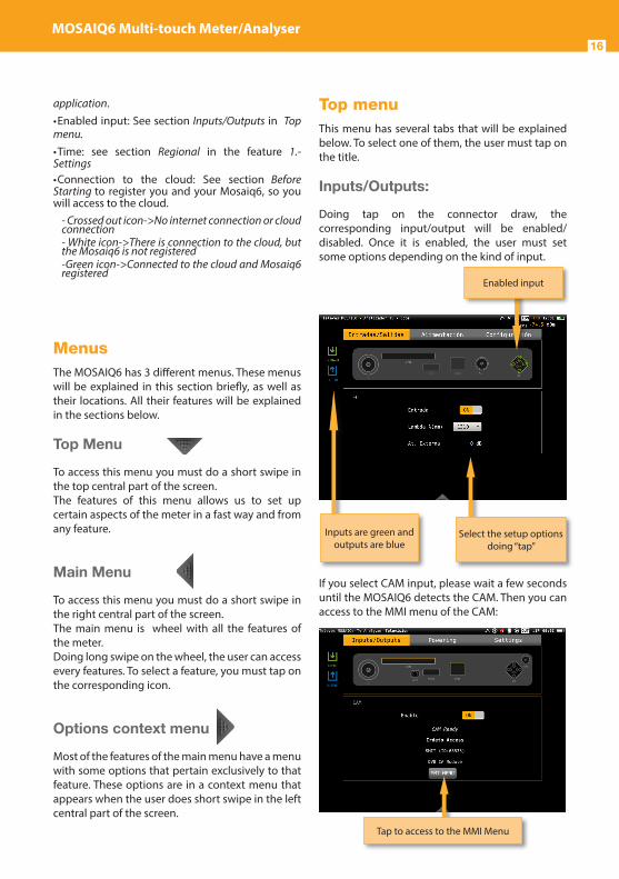
Top menuThis menu has several tabs that will be explained below. To select one of them, the user must tap on the title.
Inputs/Outputs:
Doing tap on the connector draw, the corresponding input/output will be enabled/disabled. Once it is enabled, the user must set some options depending on the kind of input.
If you select CAM input, please wait a few seconds until the MOSAIQ6 detects the CAM. Then you can access to the MMI menu of the CAM:
Inputs are green and outputs are blue
Select the setup options doing “tap”
Enabled input
Tap to access to the MMI Menu

EN
17
Powering:
Allows setup the preamplifiers powering.
Settings:
The user can set the following parameter from this menu:
• Brightness: increase/decrease the display brightness
•
•
•
•
Select doing “tap” Consumption information
Increase/decrease doing “drag”
Select the parameter doing “tap”
• Volume: increases/decreases the volume
• Touch: increases/decreases the touch control sensitivity
Increases/Decreases doing “drag”
Select parameter doing “tap”
Drag to increase/decrease
Tap to select

MOSAIQ6 Multi-touch Meter/Analyser18
• Headphones: enables/disables audio A/V output
• GPS: Enables/disables the GPS feature. When it is enabled, the corresponding icon appears on the top bar of the screen. While the MOSAIQ6 does not receive the satellite signal, the GPS icon will blink.
• Network: Allows to set up the equipment network connection. If the user selects the DHCP
Enables/Disables doing “tap”
Select parameter doing “tap”
Enables/Disables doing “tap”
Select the parameter doing “tap”
mode (DHCP ON), the network parameters will be configures automatically. If the DHCP mode is off, the user must type all the network parameters (IP, Gateway, Mask and DNS), and the do tap in “Apply”.
• Wi-Fi: enables/disables the equipment Wi-Fi connection.
Select doing “tap”
Select the parameter doing “tap”
Select the options doing “tap”
Select the parameter doing “tap”
When you “tap” on the magnifying a list with all the Wi-Fi networks will
be shown

EN
19
Main menuAll the MOSAIQ6 features are contained in this menu, and they will be explained in the following sections.
1. Settings
Allows set all the global parameters of the meter. This feature has several tabs that will be explained below:
1.1.- RegionalSets the language, the date and the time.
1.2.- MeasuresAllows to set up those parameter that are commons to all the measurements: units, frequency (if real frequency is nos checked, the meter will use IF) and LNB.
Both the measurements and the GPS coordinates will be shown in the units selected in this menu.
Tap to change date and
time
Dropdown the list doing “tap”
Check to display the date in the top bar
Check to get the network time
Select time zone
You can also select between Center or Video Carrier in the Analog Frequency dropdown list. So, when the meter is in TV Analyser function, terrestrial band, and in frequency mode, when the user enters a new frequency using the keyboard, it will correspond to the central frequency of the analog channel, or the video carrier frequency, according to the user’s selection.
1.3.- EnergyAllows set the energy-saving modes. Select the downtime until equipment auto suspension, and the downtime until auto shutdown.
Select/Deselect real frequency tapping
Dropdown tapping
Information about battery
Drag to select

MOSAIQ6 Multi-touch Meter/Analyser20
1.4.- UpdateWhen the MOSAIQ6 is connected to the internet (via Ethernet or Wi-Fi) it is automatically detected if a new firmware version is available. If so, tap on the Update button and your MOSAIQ6 will be automatically updated.
Be aware that the meter must be connected to the external powering to be updated.
This menu allows to configure the synchronization between the MOSAIQ6 and the cloud (see section MOSAIQ6 Cloud)
You can also update your device using an USB stick. To do that, save the update file in an USB stick and insert the USB stick into the USB connector of your MOSAIQ6. A message appears automatically indicating that an update is available on the USB. When you go to the Update menu, the following screen will appear:
Tap on the restore button to restore the
factory settings
Tap on the update button
to begin the proccess
Applies to the MOSAIQ6the changes synchronized
from the cloud
Allows to synchronize the
device with the cloud
1.5.- LicensesShows a list with all the licenses of your MOSAIQ6.
1.6.- AboutShows all the information about your equipment, both hardware and software.
It is also possible to open the user manual and read it in the the MOSAIQ6 screen (only compatible HW)
Tap on Update button to start updating

EN
21
.
2.1.- SetGoes to the setting feature of the main menu (see section 1.- Settings)
2.2.- AddAdds a new user profile. When you tap on this button, a popup window will open where the user must set all the required parameters.
First of all, you must type the profile’s name. Then you must select the bands you want to include in that profile and set up the parameters.
To select a band, you must select the corresponding check box. The first step is the terrestrial band, then tap on “Next” button pass to the satellite band, and finally the radio band.
Once you have finished the radio band configuration, tap on “add” button to save the user profile.
Tap to select the action
List of profilesTap to select Selected profile setting
1.5.- LicensesShows a list with all the licenses of your MOSAIQ6.
1.6.- AboutShows all the information about your equipment, both hardware and software.
It is also possible to open the user manual and read it in the the MOSAIQ6 screen (only compatible HW)
Tap on Update button to start updating
2. User profiles
Your MOSAIQ6 allows to define as many user profiles as you need. For each user profile, you must indicate what band(s) is going to measure that user profile and the main parameters.
If you select terrestrial band for a profile, you must select the channel plan, the preamplifiers powering and the norm.
If you select satellite band for a profile, you must select the channel plan, polarity, powering, SCR and DiSEqC.
If you select the radio band, you must select the DAB channel plan.

MOSAIQ6 Multi-touch Meter/Analyser22
If you include the satellite band in the profile, you must select how many satellites you want to include in that profile. Then you must set all the parameters for each one.
Each satellite plan is automatically associated with a DiSEqC command (fisrt plan with SAT A, second pland wit SAT B, and so on). So, the powering is always ON and automatically set to AUTO, but the user can select any other value.
Tap to dropdown the list and select the parameter from it
Tap to select/deselect the band
Type the new profile name
Tap to continue to the next band
Tap to cancel
2.3.- EditAllows changes in the selected profile of the list.
The process is similar to add a new profile.
2.4.- DeleteDeletes the selected profile from the list.
Configure all the necessary parameters for each satellite
Tap to select/deselect the band
Select the number of satellites
Tap to continue to the next band
Tap to cancel

EN
23
3. Optical attenuation
This feature allows to measure the optical attenuation in the fibre network in three wavelengths: 1310nm, 1490nm and 1550nm.When the user selects this features, the optical fibre input is automatically enabled.Please, see section Top Menu->Inputs/Outputs to learn how to enable the optical input.
3.1.- Main window:
3.2.- Options context menu:
List with the measurements in each wavelegth: attenuation, power and reference
Tap to select
Bar graph that represents the attenuation of each
wavelegth Enabled O.F. input icon
• Calibrate: select the wavelength (tap on the graphic or on the list) and tap on this button to calibrate it.
• Units: mW/µW, dBm.
• Auto lambda (OPS3L): OFF/ON. If ON is selected, the Hexylon synchronizes with the Televes OPS3L light source, whenever it is in auto lambda mode too, so the Hexylon gets the measurements over the three lambdas simultaneously.

MOSAIQ6 Multi-touch Meter/Analyser24
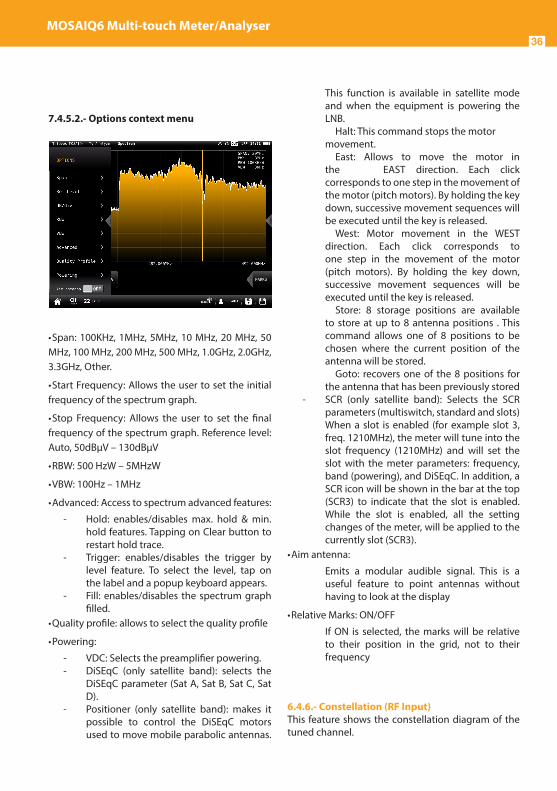
possible to control the DiSEqC motors used to move mobile parabolic antennas. This function is available in satellite mode and when the equipment is powering the LNB.
Halt: This command stops the motor movement.
East: Allows to move the motor in the EAST direction. Each click corresponds to one step in the movement of the motor (pitch motors). By holding the key down, successive movement sequences will be executed until the key is released. West: Motor movement in the WEST direction. Each click corresponds to one step in the movement of the motor (pitch motors). By holding the key down, successive movement sequences will be executed until the key is released. Store: 8 storage positions are available to store at up to 8 antenna positions . This command allows one of 8 positions to be chosen where the current position of the antenna will be stored. Goto: recovers one of the 8 positions for the antenna that has been previously stored
- SCR (only satellite band): Selects the SCR parameters (multiswitch, standard and slots) When a slot is enabled (for example slot 3, freq. 1210MHz), the meter will tune into the slot frequency (1210MHz) and will set the slot with the meter parameters: frequency, band (powering), and DiSEqC. In addition, a SCR icon will be shown in the bar at the top (SCR3) to indicate that the slot is enabled. While the slot is enabled, all the setting changes of the meter, will be applied to the currently slot (SCR3).
• Aim antenna:
Emits a modular audible signal. This is a useful feature to point antennas without having to look at the display
4. Satellite identification
This feature is able to detect automatically the satellite the input signal belongs to.
4.1.- Main window
4.2.- Options context menu
• Powering:
- VDC: Selects the preamplifier powering. - DiSEqC (only satellite band): selects the
DiSEqC parameter (Sat A, Sat B, Sat C, Sat D).
- Positioner (only satellite band): makes it
Once the satellite is identified, the name is shown in the display
The Mosaiq6 adjusts automatically all the paramenters of the spectrum
EN
25
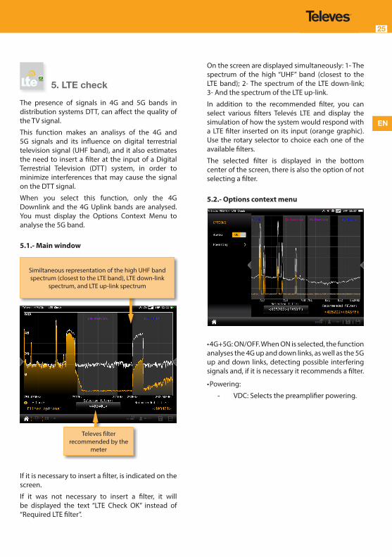
5. LTE check
The presence of signals in 4G and 5G bands in distribution systems DTT, can affect the quality of the TV signal.
This function makes an analisys of the 4G and 5G signals and its influence on digital terrestrial television signal (UHF band), and it also estimates the need to insert a filter at the input of a Digital Terrestrial Television (DTT) system, in order to minimize interferences that may cause the signal on the DTT signal.
When you select this function, only the 4G Downlink and the 4G Uplink bands are analysed. You must display the Options Context Menu to analyse the 5G band.
5.1.- Main window
If it is necessary to insert a filter, is indicated on the screen.
If it was not necessary to insert a filter, it will be displayed the text “LTE Check OK” instead of “Required LTE filter”.
Televes filter recommended by the
meter
Similtaneous representation of the high UHF band spectrum (closest to the LTE band), LTE down-link
spectrum, and LTE up-link spectrum
On the screen are displayed simultaneously: 1- The spectrum of the high “UHF” band (closest to the LTE band); 2- The spectrum of the LTE down-link; 3- And the spectrum of the LTE up-link.
In addition to the recommended filter, you can select various filters Televés LTE and display the simulation of how the system would respond with a LTE filter inserted on its input (orange graphic). Use the rotary selector to choice each one of the available filters.
The selected filter is displayed in the bottom center of the screen, there is also the option of not selecting a filter.
5.2.- Options context menu
• 4G+5G: ON/OFF. When ON is selected, the function analyses the 4G up and down links, as well as the 5G up and down links, detecting possible interfering signals and, if it is necessary it recommends a filter.
• Powering:
- VDC: Selects the preamplifier powering.
MOSAIQ6 Multi-touch Meter/Analyser26
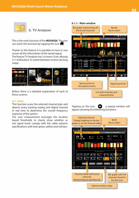
6.1.1.- Main window
Tapping on the icon a popup window will appear showing the following functions:
:
Tap to access to the options menu
Bar graph representing all the found channels
BandaTap to select
List with channels and measurements
Signal spectrum
Channel table with found channels
Vertical drag to see them all
Selected channelChange tapping on the bar
graph or on the channel tableBand
Tap to select
Options buttons (tap)
Bar graph with the channels found in
the last scan
6. TV Analyser
This is the main function of the MOSAIQ6. The user can reach this function by tapping the icon .
Thanks to this feature it is possible to have in one screen all the information of the tuned signal.The feature TV Analyser has 3 screens: Scan, Mosaiq 3+1 & Mosaiq 6. To switch between screens do long swipe.
Bellow there is a detailed explanation of each of these screens:
6.1.- ScanThis function scans the selected channel plan and detects every existing analog and digital channel in real time to determine the overall frequency response of the system. The scan measurement leverages the location based thresholds to clearly show whether or not signal levels comply with the cable system’s specifications with their green, yellow and red bars.

EN
27
• Start: Starts a new system scan
• Options:
- Fast: ON/OFF. When the fast scan is enabled (ON), the meter will not make CBER and VBER measurements for digital channels, neither V/A measurements for analog channels. So, only power and level measurements will be shown.
- Wide outlet: ON/OFF. Enable this option when the outlet in your installation has both terrestrial and satellite bands. So, both bands will be scanned consecutively. If this options is disabled, only the selected band will be scanned.Note: Note that if the selected user profile does not allow to make measurements in some bands, the scan will not be done in that band.
• Edit: Allows to add/delete channels from the plan. If the channel is selected (orange coloured), when you tap on it, it will be deselected. Otherwise, if the channel is unselected (grey coloured), when you tap on it, it will be selected.
• Save: Saves a new plan with the found channels.
• Cancel: Closes the options window.
6.1.2.- Options context menu
• Fast: ON/OFF. When the fast scan is enabled (ON), the meter will not make CBER and VBER measurements for digital channels, neither V/A measurements for analog channels. So, only power and level measurements will be shown.
• Wide outlet: ON/OFF. Enable this option when the outlet in your installation has both terrestrial and satellite bands. So, both bands will be scanned consecutively. If this options is disabled, only the selected band will be scanned.
Note: Note that if the selected user profile does not allow to make measurements in some bands, the scan will not be done in that band.
• Show all: ON/OFF. When show all is ON, all the measurements of all the channels are shown. When it is OFF, you can only see the measurements of the channel that is being measured in that moment.
• Span full: ON/OFF. When Span full ins ON you can see all the bars corresponding to all the found channels. When this option is OFF, only 24 bars are shown, so it is necessary to scroll to see them all.
• Tilt: ON/OFF. When the tilt option is ON, this function measures the tilt between the channels indicated in the labels CH A and CH B. Then you can see a white line between these two channels and the tilt measurement on it.
• Attenuation: ON/OFF. When the attenuation option is ON, the MOSAIQ6 measures the attenuation of the installation relative to a reference point, usually the head-end output. So, the first thing you must do is connect the meter to the reference point and tap on the Calibrate button. In this way, the equipment will measure and save the level of all the channels.
Then you must go to all the pints of the installation where we want to measure and connect the meter, taking care to have this function ON. The MOSAIQ6 will measure the levels of all the channels comparing them with the reference ones.
When this option is ON, the bars of the graphic don’t represent the level or the power of the channels, but the attenuation of each one of them. The list shows power (or level) and C/N. In addition, a green trace is shown in the spectrum. This trace indicates the levels in the reference point.
• Quality profile: allows to select the quality profile .
• Powering:
- VDC: Selects the preamplifier powering.

MOSAIQ6 Multi-touch Meter/Analyser28
- DiSEqC (only satellite band): selects the DiSEqC parameter (Sat A, Sat B, Sat C, Sat D).
- Positioner (only satellite band): makes it possible to control the DiSEqC motors used to move mobile parabolic antennas. This function is available in satellite mode and when the equipment is powering the LNB.
Halt: This command stops the motor movement.
East: Allows to move the motor in the EAST direction. Each click corresponds to one step in the movement of the motor (pitch motors). By holding the key down, successive movement sequences will be executed until the key is released. West: Motor movement in the WEST direction. Each click corresponds to one step in the movement of the motor (pitch motors). By holding the key down, successive movement sequences will be executed until the key is released. Store: 8 storage positions are available to store at up to 8 antenna positions . This command allows one of 8 positions to be chosen where the current position of the antenna will be stored. Goto: recovers one of the 8 positions for the antenna that has been previously stored
- SCR (only satellite band): Selects the SCR parameters (multiswitch, standard and slots) When a slot is enabled (for example slot 3, freq. 1210MHz), the meter will tune into the slot frequency (1210MHz) and will set the slot with the meter parameters: frequency, band (powering), and DiSEqC. In addition, a SCR icon will be shown in the bar at the top (SCR3) to indicate that the slot is enabled. While the slot is enabled, all the setting changes of the meter, will be applied to the currently slot (SCR3).
6.2.- Mosaiq 3+1This screen has 4 widgets, 3 in the top of the screen and one in the lower part of the screen. Theses widgets ares user-configurable, that is, the user can select the the function he or she wants to visualize in each widget.
6.2.1.- Main window
All the available features are explained in section 6.4.- Features.
6.2.2.- Options context menu:
• Quality profile: allows to select the quality profile
• Powering:
- VDC: Selects the preamplifier powering. - DiSEqC (only satellite band): selects the
DiSEqC parameter (Sat A, Sat B, Sat C, Sat D). - Positioner (only satellite band): makes it
possible to control the DiSEqC motors used
Swipe on the spectrum to chage the channel
Tap on the title bar of the widget to change the
function
Double tap to see the function in full screen

EN
29
to move mobile parabolic antennas. This function is available in satellite mode and when the equipment is powering the LNB.
Halt: This command stops the motor movement.
East: Allows to move the motor in the EAST direction. Each click corresponds to one step in the movement of the motor (pitch motors). By holding the key down, successive movement sequences will be executed until the key is released. West: Motor movement in the WEST direction. Each click corresponds to one step in the movement of the motor (pitch motors). By holding the key down, successive movement sequences will be executed until the key is released. Store: 8 storage positions are available to store at up to 8 antenna positions . This command allows one of 8 positions to be chosen where the current position of the antenna will be stored. Goto: recovers one of the 8 positions for the antenna that has been previously stored.
- SCR (only satellite band): Selects the SCR parameters (multiswitch, standard and slots) When a slot is enabled (for example slot 3, freq. 1210MHz), the meter will tune into the slot frequency (1210MHz) and will set the slot with the meter parameters: frequency, band (powering), and DiSEqC. In addition, a SCR icon will be shown in the bar at the top (SCR3) to indicate that the slot is enabled. While the slot is enabled, all the setting changes of the meter, will be applied to the currently slot (SCR3).
6.3.- Mosaiq 6
This screen has 6 widgets. Theses widgets ares user-configurable, that is, the user can select the function he or she wants to visualize in each widget.
6.3.1.- Main window
All the available features are explained in section 6.4.- Features.
6.3.2.- Options context menu
• Quality profile: allows to select the quality profile
• Powering:
- VDC: Selects the preamplifier powering.
Swipe on the spectrum to chage the channel
Tap on the title bar of the widget to change the
function
Double tap to see the function in full screen

MOSAIQ6 Multi-touch Meter/Analyser30
- DiSEqC (only satellite band): selects the DiSEqC parameter (Sat A, Sat B, Sat C, Sat D).
- Positioner (only satellite band): makes it possible to control the DiSEqC motors used to move mobile parabolic antennas. This function is available in satellite mode and when the equipment is powering the LNB.
Halt: This command stops the motor movement.
East: Allows to move the motor in the EAST direction. Each click corresponds to one step in the movement of the motor (pitch motors). By holding the key down, successive movement sequences will be executed until the key is released. West: Motor movement in the WEST direction. Each click corresponds to one step in the movement of the motor (pitch motors). By holding the key down, successive movement sequences will be executed until the key is released. Store: 8 storage positions are available to store at up to 8 antenna positions . This command allows one of 8 positions to be chosen where the current position of the antenna will be stored. Goto: recovers one of the 8 positions for the antenna that has been previously stored
- SCR (only satellite band): Selects the SCR parameters (multiswitch, standard and slots) When a slot is enabled (for example slot 3, freq. 1210MHz), the meter will tune into the slot frequency (1210MHz) and will set the slot with the meter parameters: frequency, band (powering), and DiSEqC. In addition, a SCR icon will be shown in the bar at the top (SCR3) to indicate that the slot is enabled. While the slot is enabled, all the setting changes of the meter, will be applied to the currently slot (SCR3).
6.4.- FeaturesThis section explains all the features available to visualize in the widgets of the Mosaiq 3+1 and Mosaiq 6 modes.
Note: If the ASI input is selected, only Television
and Services features will be available.
6.4.1.- TelevisionThis feature allows to visualize the selected service ‘s image of the tuned channel.
Note: When the image is not available, one of these icons will be shown:
• Only audio service
• Encrypted channel
• Data service
6.4.1.1.- Main window
Tap on the service’s name to see all the information about it
Tap to see the list of services

EN
31
Tapping on the screen, it appears a popup window with the list of the channel’s services:
Next to the name of the service, the icons indicating the transports are shown (image, one or more audio transports). To change the audio, tap again on the screen and select the same service in the list, then a new pop-up window will appear showind the available audios.
Tapping on the service’s name, it appears a popup window with the information about it:
Tap on the service to select it
Tap to close the popup window
6.4.1.2.- Options context menu
• Quality profile: allows to select the quality profile
• Powering:
- VDC: Selects the preamplifier powering. - DiSEqC (only satellite band): selects the
DiSEqC parameter (Sat A, Sat B, Sat C, Sat D).
- Positioner (only satellite band): makes it possible to control the DiSEqC motors used to move mobile parabolic antennas. This function is available in satellite mode and when the equipment is powering the LNB.
Halt: This command stops the motor movement.
East: Allows to move the motor in the EAST direction. Each click corresponds to one step in the movement of the motor (pitch motors). By holding the key down, successive movement sequences will be executed until the key is released. West: Motor movement in the WEST direction. Each click corresponds to one step in the movement of the motor (pitch motors). By holding the key down, successive movement sequences will be executed until the key is released. Store: 8 storage positions are available to store at up to 8 antenna positions . This command allows one of 8 positions to be chosen where the current position of the antenna will be stored. Goto: recovers one of the 8 positions for the antenna that has been previously stored

MOSAIQ6 Multi-touch Meter/Analyser32
- SCR (only satellite band): Selects the SCR parameters (multiswitch, standard and slots) When a slot is enabled (for example slot 3, freq. 1210MHz), the meter will tune into the slot frequency (1210MHz) and will set the slot with the meter parameters: frequency, band (powering), and DiSEqC. In addition, a SCR icon will be shown in the bar at the top (SCR3) to indicate that the slot is enabled. While the slot is enabled, all the setting changes of the meter, will be applied to the currently slot (SCR3).
6.4.2.- ServicesThis features shows a graph with the distribution of the services os the channel. Tapping on one of the sections of the graph, you can see the name of the corresponding service.If you see this feature in full screen, you will have more detailed information.
6.4.2.1.- Main window
Distribution and bitrates of the service
PIDs
Graph with the distribution of the channels services
List of services with ID, the LCN (for DVB channels)or the Virtual
Channel (for ISDB-T channels), the service name, and bitrates. The
color of the squares corresponds to the color of the section in the
graph
Service PIDs. The colors of the squares indicate the
PID type
6.4.2.2.- Options context menu
• Quality profile: allows to select the quality profile
• Powering:
- VDC: Selects the preamplifier powering. - DiSEqC (only satellite band): selects the
DiSEqC parameter (Sat A, Sat B, Sat C, Sat D). - Positioner (only satellite band): makes it
possible to control the DiSEqC motors used to move mobile parabolic antennas. This function is available in satellite mode and when the equipment is powering the LNB.
Halt: This command stops the motor movement.
East: Allows to move the motor in the EAST direction. Each click corresponds to one step in the movement of the motor (pitch motors). By holding the key down, successive movement sequences will be executed until the key is released. West: Motor movement in the WEST direction. Each click corresponds to one step in the movement of the motor (pitch motors). By holding the key down, successive movement sequences will be executed until the key is released. Store: 8 storage positions are available to store at up to 8 antenna positions . This command allows one of 8 positions to be chosen where the current position of the antenna will be stored. Goto: recovers one of the 8 positions for the antenna that has been previously stored.
- SCR (only satellite band): Selects the SCR parameters (multiswitch, standard and slots)

EN
33
When a slot is enabled (for example slot 3, freq. 1210MHz), the meter will tune into the slot frequency (1210MHz) and will set the slot with the meter parameters: frequency, band (powering), and DiSEqC. In addition, a SCR icon will be shown in the bar at the top (SCR3) to indicate that the slot is enabled. While the slot is enabled, all the setting changes of the meter, will be applied to the currently slot (SCR3).
6.4.3.-ParametersThis feature shows the parameters of the locked signal.
6.4.3.1.- Main Window
List of parameters
Tap on the pencil to edit the standard, the BW, and the
PLS n or root
6.4.3.2.- Options context menu
• Powering:
- VDC: Selects the preamplifier powering. - DiSEqC (only satellite band): selects the
DiSEqC parameter (Sat A, Sat B, Sat C, Sat D)
- Positioner (only satellite band): makes it possible to control the DiSEqC motors used to move mobile parabolic antennas. This function is available in satellite mode and when the equipment is powering the LNB.
Halt: This command stops the motor movement.
East: Allows to move the motor in the EAST direction. Each click corresponds to one step in the movement of the motor (pitch motors). By holding the key down, successive movement sequences will be executed until the key is released. West: Motor movement in the WEST direction. Each click corresponds to one step in the movement of the motor (pitch motors). By holding the key down, successive movement sequences will be executed until the key is released. Store: 8 storage positions are available to store at up to 8 antenna positions . This command allows one of 8 positions to be chosen where the current position of the antenna will be stored. Goto: recovers one of the 8 positions for the antenna that has been previously stored
- SCR (only satellite band): Selects the SCR
MOSAIQ6 Multi-touch Meter/Analyser34
parameters (multiswitch, standard and slots) When a slot is enabled (for example slot 3, freq. 1210MHz), the meter will tune into the slof frequency (1210MHz) and will set the slot with the meter parameters: frequency, band (powering), and DiSEqC. In addition, a SCR icon will be shown in the bar at the top (SCR3) to indicate thar the slot is enabled. While the slot is enabled, all the setting changes of the meter, will be applied to the currently slot (SCR3).
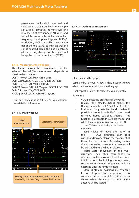
6.4.4.- Measurements (RF input)This feature shows the measurements of the selected channel. The measurements depends on the signal modulation:DVB-S: Power, C/N, MER, CBER, VBER DVB-S2: Power, C/N, MER, LDPCBER, BCHBER DVB-T: Power, C/N, MER, CBER, VBER DVB-T2: Power, C/N, Link Margin, LDPCBER, BCHBER DVB-C: Power, C/N, CBER, MER Analog: Level, C/N, V/A, HUM, CTB, CSO
If you see this feature in full screen, you will have more detailed information.
6.4.4.1.- Main window
History of the measurements during an interval selected by the user. Drag to move the blue mark
List of measurements Listof signal parameters
6.4.4.2.- Options context menu
• Clear: restarts the graph.
• Last: 5 min, ½ hour, ½ day, 1 day, 1 week. Allows select the time interval shown in the graph
• Quality profile: allows to select the quality profile
• Powering:
- VDC: Selects the preamplifier powering. - DiSEqC (only satellite band): selects the
DiSEqC parameter (Sat A, Sat B, Sat C, Sat D). - Positioner (only satellite band): makes it
possible to control the DiSEqC motors used to move mobile parabolic antennas. This function is available in satellite mode and when the equipment is powering the LNB.
Halt: This command stops the motor movement.
East: Allows to move the motor in the EAST direction. Each click corresponds to one step in the movement of the motor (pitch motors). By holding the key down, successive movement sequences will be executed until the key is released. West: Motor movement in the WEST direction. Each click corresponds to one step in the movement of the motor (pitch motors). By holding the key down, successive movement sequences will be executed until the key is released. Store: 8 storage positions are available to store at up to 8 antenna positions . This command allows one of 8 positions to be chosen where the current position of the antenna will be stored.

EN
35
Goto: recovers one of the 8 positions for the antenna that has been previously stored
- SCR (only satellite band): Selects the SCR parameters (multiswitch, standard and slots) When a slot is enabled (for example slot 3, freq. 1210MHz), the meter will tune into the slot frequency (1210MHz) and will set the slot with the meter parameters: frequency, band (powering), and DiSEqC. In addition, a SCR icon will be shown in the bar at the top (SCR3) to indicate that the slot is enabled. While the slot is enabled, all the setting changes of the meter, will be applied to the currently slot (SCR3).
- CTB (only analog channels): Turns ON/OFF the CTB measuremnt. If you select CTB ON, a popup window will be displayed asking you to turn the signal off. CTB can only be made with the service disabled, because it is a measurement made in the frequency of the video carrier of the TV signal. Turn the signal ON again to measure CTB and all other measurements properly.
- CSO Offsets (only analog channels): The CSO measure is carried out in different frequencies (at different distances from the video carrier) within the selected channel. Using this menu you can select the offset where you want to measure the CSO, and you can save up to 6 offset values, that can be the default values or user-selected ones.
6.4.5.- Spectrum (RF Input)This feature shows the spectrum of the signal.
6.4.5.1.-Main window
If you tap to enable marks:
Power or C/N measurement.Tap to change
Spectrum parameters
Swipe to tune next/previous channelDrag to tune any channel
Spread/Pinch to change span
Tap to enable/disable marks
Drag to move the active mark
Tap to activate a mark+ adds a new mark (max. 6). - removes the active mark
Delta: measures the level difference between two marks
MOSAIQ6 Multi-touch Meter/Analyser36
7.4.5.2.- Options context menu
• Span: 100KHz, 1MHz, 5MHz, 10 MHz, 20 MHz, 50 MHz, 100 MHz, 200 MHz, 500 MHz, 1.0GHz, 2.0GHz, 3.3GHz, Other.
• Start Frequency: Allows the user to set the initial frequency of the spectrum graph.
• Stop Frequency: Allows the user to set the final frequency of the spectrum graph. Reference level: Auto, 50dBµV – 130dBµV
• RBW: 500 HzW – 5MHzW
• VBW: 100Hz – 1MHz
• Advanced: Access to spectrum advanced features:
- Hold: enables/disables max. hold & min. hold features. Tapping on Clear button to restart hold trace.
- Trigger: enables/disables the trigger by level feature. To select the level, tap on the label and a popup keyboard appears.
- Fill: enables/disables the spectrum graph filled.
• Quality profile: allows to select the quality profile
• Powering:
- VDC: Selects the preamplifier powering. - DiSEqC (only satellite band): selects the
DiSEqC parameter (Sat A, Sat B, Sat C, Sat D).
- Positioner (only satellite band): makes it possible to control the DiSEqC motors used to move mobile parabolic antennas.
This function is available in satellite mode and when the equipment is powering the LNB.
Halt: This command stops the motor movement.
East: Allows to move the motor in the EAST direction. Each click corresponds to one step in the movement of the motor (pitch motors). By holding the key down, successive movement sequences will be executed until the key is released. West: Motor movement in the WEST direction. Each click corresponds to one step in the movement of the motor (pitch motors). By holding the key down, successive movement sequences will be executed until the key is released. Store: 8 storage positions are available to store at up to 8 antenna positions . This command allows one of 8 positions to be chosen where the current position of the antenna will be stored. Goto: recovers one of the 8 positions for the antenna that has been previously stored
- SCR (only satellite band): Selects the SCR parameters (multiswitch, standard and slots) When a slot is enabled (for example slot 3, freq. 1210MHz), the meter will tune into the slot frequency (1210MHz) and will set the slot with the meter parameters: frequency, band (powering), and DiSEqC. In addition, a SCR icon will be shown in the bar at the top (SCR3) to indicate that the slot is enabled. While the slot is enabled, all the setting changes of the meter, will be applied to the currently slot (SCR3).
• Aim antenna:
Emits a modular audible signal. This is a useful feature to point antennas without having to look at the display
• Relative Marks: ON/OFF
If ON is selected, the marks will be relative to their position in the grid, not to their frequency
6.4.6.- Constellation (RF Input)This feature shows the constellation diagram of the tuned channel.

EN
37
6.4.6.1.- Main window
6.4.6.2.- Options context menu
• Grid: ON/OFF. Shows/hide the grid.
• Carrier (only DVB-T/T2): All, TPS+continual (only DVB-T), Other. Allows you to select the constelation of the selected carrier(s).• Layer (only ISDB-T/Tb): Allows to select the layer whose constellation must be displayed.
• Quality profile: allows to select the quality profile
• Powering:
Constellation diagramSpread/Pinch to zoom in/out
List of measurements of the channelTap on i to see the parameters of the signal
- VDC: Selects the preamplifier powering. - DiSEqC (only satellite band): selects the
DiSEqC parameter (Sat A, Sat B, Sat C, Sat D).
- Positioner (only satellite band): makes it possible to control the DiSEqC motors used to move mobile parabolic antennas. This function is available in satellite mode and when the equipment is powering the LNB.
Halt: This command stops the motor movement.
East: Allows to move the motor in the EAST direction. Each click corresponds to one step in the movement of the motor (pitch motors). By holding the key down, successive movement sequences will be executed until the key is released. West: Motor movement in the WEST direction. Each click corresponds to one step in the movement of the motor (pitch motors). By holding the key down, successive movement sequences will be executed until the key is released. Store: 8 storage positions are available to store at up to 8 antenna positions . This command allows one of 8 positions to be chosen where the current position of the antenna will be stored. Goto: recovers one of the 8 positions for the antenna that has been previously stored -SCR (only satellite band): Selects the SCR
parameters (multiswitch, standard and slots) When a slot is enabled (for example slot 3, freq. 1210MHz), the meter will tune into the slot frequency (1210MHz) and will set the slot with the meter parameters: frequency, band (powering), and DiSEqC. In addition, a SCR icon will be shown in the bar at the top (SCR3) to indicate that the slot is enabled. While the slot is enabled, all the setting changes of the meter, will be applied to the currently slot (SCR3).
6.4.7.- Echoes (RF Input)This feature you allows to visualize the echoes of the received signal, helping the installer to minimize them as much as possible for optimal signal reception.

MOSAIQ6 Multi-touch Meter/Analyser38
6.4.7.1.- Main window
6.4.7.2.- Options context menu:
• Min. Level: allows to indicate the level from which the meter must take account of the echoes. You can also change this level by dragging the horizontal orange level.• Zoom: OFF, 2x, 4x, 8x, 16x. You can also Spread/pinch on the screen.• Units: us, Km.
List of measurements of the channel
Tap on i to see the parameters of the signal
The blue mark indicates the delay and the level of
the signalDrag to move
Orange mark indicates the minimun level of the
echoesDrag to move
List of echoes with the delay
and level of each one
• Quality profile: allows to select the quality profile
• Powering:
- VDC: Selects the preamplifier powering. - DiSEqC (only satellite band): selects the
DiSEqC parameter (Sat A, Sat B, Sat C, Sat D). - Positioner (only satellite band): makes it
possible to control the DiSEqC motors used to move mobile parabolic antennas. This function is available in satellite mode and when the equipment is powering the LNB.
Halt: This command stops the motor movement.
East: Allows to move the motor in the EAST direction. Each click corresponds to one step in the movement of the motor (pitch motors). By holding the key down, successive movement sequences will be executed until the key is released. West: Motor movement in the WEST direction. Each click corresponds to one step in the movement of the motor (pitch motors). By holding the key down, successive movement sequences will be executed until the key is released. Store: 8 storage positions are available to store at up to 8 antenna positions . This command allows one of 8 positions to be chosen where the current position of the antenna will be stored. Goto: recovers one of the 8 positions for the antenna that has been previously stored
- SCR (only satellite band): Selects the SCR parameters (multiswitch, standard and slots) When a slot is enabled (for example slot 3, freq. 1210MHz), the meter will tune into the slot frequency (1210MHz) and will set the slot with the meter parameters: frequency, band (powering), and DiSEqC. In addition, a SCR icon will be shown in the bar at the top (SCR3) to indicate that the slot is enabled. While the slot is enabled, all the setting changes of the meter, will be applied to the currently slot (SCR3).
6.4.8.- MER/carrier (RF Input)This feature represents MER value for each carrier of the DVB-T signal. This is pretty useful to detect if there is any interference inside the channel that makes the

EN
39
quality signal to get worse and that is invisible for a traditional spectral analysis.
6.4.8.1.- Main window
• MER RMS: Average MER of the DVB-T signal.
• MER max: Maximum MER value of the DVB-T signal. In parentheses the number of carrier with this maximum valuer of MER. If you tap on this measurement, the blue mark will move to the carrier with the maximum MER, and will be moving searching the carrier with maximum MER each time.
• MER min: Minimum MER value of the DVB-T signal. In parentheses the number of carrier with this minimum valuer of MER. If you tap on this measurement, the blue mark will move to the carrier with the minimum MER, and will be moving searching the carrier with minimum MER each time.
List of measurements of the selected channel
Tap on i to see the parameters
The blue mark indicates the MER of the carrier where
the mark is placed
The orange mark indicates the average
MER of the carriers
Average, maximum and minimum MER
values
6.4.8.2.- Options context menu
• Carrier: Allows to select the carrier where the user wants to measure the MER.
• Quality profile: allows to select the quality profile
• Powering:
- VDC: Selects the preamplifier powering. • Min. Carrier: Allows you to select the minimum carrier to be shown in the graph.
• Max. Carrier: Allows you to select the maximum carrier to be shown in the graph.
• Reset Positions: Sets the minimum and maximum carriers shown in the graph to the maximum and minimum carriers of the channel.
6.4.9.- Uncorrected packets (RF Input)This feature makes an uncorrected packet analysis during a timer interval selected by the user.

MOSAIQ6 Multi-touch Meter/Analyser40
6.4.9.1.- Main window
Total analysis: Start and end time of the analysis, and number of uncorrected packets in all the intervals analysed.Current interval: Start and end time of the current interval, and number of uncorrected packets.Previous interval: Start and end time of the previous interval and number of uncorrected packets.Worst interval: Start and end time of the interval with more uncorrected packets, and number of uncorrected packets in the worst interval of analysis since it was started.
Locked: Time gone by since the demodulator locked to the digital signal the last time, longest time the digital signal was locked, and number of locking.Unlocked: Time gone by since the demodulator unlocked to the digital signal the last time, longest time the digital signal was unlocked, and number of unlocking.Error-free: Time gone by since last uncorrected packet, and longest time gone by since last uncorrected packet.
Data about unlockings
Data of the uncorrected packets analysis
6.4.9.2.- Options context menu:
• Restart: restart the uncorrected packets analysis
• Interval: Change the analysis interval time. The interval is configurable between 1 minute and 1 hour.
• Powering:
- VDC: Selects the preamplifier powering. - DiSEqC (only satellite band): selects the
DiSEqC parameter (Sat A, Sat B, Sat C, Sat D). - Positioner (only satellite band): makes it
possible to control the DiSEqC motors used to move mobile parabolic antennas. This function is available in satellite mode and when the equipment is powering the LNB.
Halt: This command stops the motor movement.
East: Allows to move the motor in the EAST direction. Each click corresponds to one step in the movement of the motor (pitch motors). By holding the key down, successive movement sequences will be executed until the key is released. West: Motor movement in the WEST direction. Each click corresponds to one step in the movement of the motor (pitch motors). By holding the key down, successive movement sequences will be executed until the key is released. Store: 8 storage positions are available to store at up to 8 antenna positions . This command allows one of 8 positions to be chosen where the current position of the antenna will be stored. Goto: recovers one of the 8 positions for the antenna that has been previously stored
- SCR (only satellite band): Selects the SCR
EN
41
parameters (multiswitch, standard and slots) When a slot is enabled (for example slot 3, freq. 1210MHz), the meter will tune into the slot frequency (1210MHz) and will set the slot with the meter parameters: frequency, band (powering), and DiSEqC. In addition, a SCR icon will be shown in the bar at the top (SCR3) to indicate that the slot is enabled. While the slot is enabled, all the setting changes of the meter, will be applied to the currently slot (SCR3).
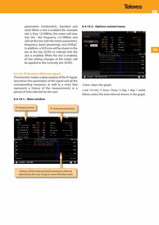
6.4.10.-IP Analysis (Ethernet Input)This function makes a deep analysis of the IP signal, and shows the parameters of the signal and all the corresponding measures, as well as a chart that represents a history of the measurements in a period of time selected by the user.
6.4.10.1.- Main window
IP channel parametersIP measurements
History of the measurements during an interval selected by the user. Drag to move the blue mark
6.4.10.2.- Options context menu
•
• Clear: clears the graph.
• Last: 10 min, ½ hour, 1hour, ½ day, 1 day, 1 week. Allows select the time interval shown in the graph.
MOSAIQ6 Multi-touch Meter/Analyser42
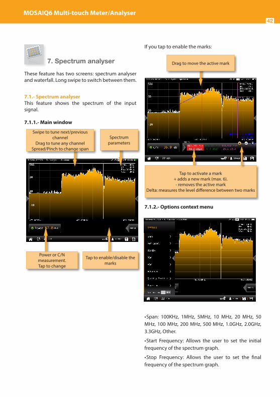
7. Spectrum analyser
These feature has two screens: spectrum analyser and waterfall. Long swipe to switch between them.
7.1.- Spectrum analyserThis feature shows the spectrum of the input signal.
7.1.1.- Main window
Power or C/N measurement.Tap to change
Spectrum parameters
Swipe to tune next/previous channel
Drag to tune any channelSpread/Pinch to change span
Tap to enable/disable the marks
If you tap to enable the marks:
7.1.2.- Options context menu
• Span: 100KHz, 1MHz, 5MHz, 10 MHz, 20 MHz, 50 MHz, 100 MHz, 200 MHz, 500 MHz, 1.0GHz, 2.0GHz, 3.3GHz, Other.
• Start Frequency: Allows the user to set the initial frequency of the spectrum graph.
• Stop Frequency: Allows the user to set the final frequency of the spectrum graph.
Drag to move the active mark
Tap to activate a mark+ adds a new mark (max. 6). - removes the active mark
Delta: measures the level difference between two marks

EN
43
• Reference level: Auto, 50dBµV – 130dBµV
• RBW: 500 HzW – 5MHzW
• VBW: 100Hz – 1MHz
• Advanced: Access to spectrum advanced features:
- Hold: enables/disables max. hold & min. hold features. Tapping on Clear button to restart hold trace.
- Trigger: enables/disables the trigger by level feature. To select the level, tap on the label and a popup keyboard appears.
- Fill: enables/disables the spectrum graph filled.
• Quality profile: allows to select the quality profile
• Powering:
- VDC: Selects the preamplifier powering. - DiSEqC (only satellite band): selects the
DiSEqC parameter (Sat A, Sat B, Sat C, Sat D).
- Positioner (only satellite band): makes it possible to control the DiSEqC motors used to move mobile parabolic antennas. This function is available in satellite mode and when the equipment is powering the LNB.
Halt: This command stops the motor movement.
East: Allows to move the motor in the EAST direction. Each click corresponds to one step in the movement of the motor (pitch motors). By holding the key down, successive movement sequences will be executed until the key is released. West: Motor movement in the WEST direction. Each click corresponds to one step in the movement of the motor (pitch motors). By holding the key down, successive movement sequences will be executed until the key is released. Store: 8 storage positions are available to store at up to 8 antenna positions . This command allows one of 8 positions to be chosen where the current position of the antenna will be stored. Goto: recovers one of the 8 positions for the antenna that has been previously stored
- SCR (only satellite band): Selects the SCR parameters (multiswitch, standard and slots) When a slot is enabled (for example
slot 3, freq. 1210MHz), the meter will tune into the slot frequency (1210MHz) and will set the slot with the meter parameters: frequency, band (powering), and DiSEqC. In addition, a SCR icon will be shown in the bar at the top (SCR3) to indicate that the slot is enabled. While the slot is enabled, all the setting changes of the meter, will be applied to the currently slot (SCR3).
• Aim antenna:
Emits a modular audible signal. This is a useful feature to point antennas without having to look at the display
• Relative Marks: ON/OFF
If ON is selected, the marks will be relative to their position in the grid, not to their frequency.
7.2.- WaterfallThe waterfall diagram is a three-dimensional representation of the signal spectrum. Signal levels are converted to colours and displayed along a time axis.
7.2.1.- Main window
Waterfall time axis is the vertical one and frequency axis is the horizontal one, while level is converted to colour
through the colour scale in the top right side
Spectrum parameters
Swipe to tune next/previous channel
Drag to tune any channelSpread/Pinch to change span

MOSAIQ6 Multi-touch Meter/Analyser44
Every spectrum trace in the top half generates a new waterfall line in the bottom half.
7.2.2.- Options context menu:
• Clear: It clears the waterfall display.
• Reference: it changes the level of the highest colour in the colour scale. Signal levels above this reference will be displayed in this colour.
• Range: it changes difference in dB between the highest and the lowest colour of the colour scale on the waterfall display.
• Colours: it changes the colour palette. Different colour combinations can be selected for the waterfall representation (Jet, Hot and BlueHot).
• Frame beep: when this option is ON, a beep sounds each time the waterfall screen fully refreshes, so there is no need to look at the screen continuously. Looking at the screen just when the beep sounds guarantees not missing any waterfall information.
• Spectrum: accesses to the spectrum options context menu (see section 7.1.- Spectrum analyser).
8. Radio Analyser
This feature is similar to TV Analysis in the radio band. So it has two screens: scan and mosaiq 3+1. Long swipe to switch between them.
8.1.- Scan RadioThis features scans the FM and DAB band.
The scan measurement leverages the location based thresholds to clearly show whether or not signal levels comply with the cable system’s specifications with their green, yellow and red bar.
8.3.1.- Main window
Tap to access to the options menu
Bar graph representing all the found channels
Band.Tap to change
List of channels and measurements
Signal spectrum

EN
45
Tapping on icon a popup window will appear:
• Start: Starts a new system scan
• Options:
- Fast: ON/OFF. When the fast scan is enabled (ON), the meter will not make CBER and MER measurements for DAB channels. So, only power and C/N measurements will be shown.
- Wide outlet: ON/OFF. Enable this option when the outlet in your installation has both terrestrial and satellite bands. So, both bands will be scanned consecutively. If this options is disabled, only the selected band will be scanned.Note: Note that if the selected user profile does not allow to make measurements in some bands, the scan will not be done in that band.
• Edit: Allows to add/delete channels from the plan. If the channel is selected (orange coloured), when you tap on it, it will be deselected. Otherwise, if the channel is unselected (grey coloured), when you tap on it, it will be selected.
• Save: Saves a new plan with the found channels.
Table with found channelsScroll to see them all
Selected channelChange tapping on the bar
graph or on the channel table
Options buttons
Bar graph with the channels found in
the last scan
• Cancel: Closes the options window
8.3.2.- Options context menu
• Fast: ON/OFF. When the fast scan is enabled (ON), the meter will not make CBER and MER measurements for DAB channels. So, only power and C/N measurements will be shown.
• Show all: ON/OFF. When show all is ON, all the measurements of all the channels are shown. When it is OFF, you can only see the measurements of the channel that is being measured in that moment.
• Span full: ON/OFF. When Span full ins ON you can see all the bars corresponding to all the found channels. When this option is OFF, only 24 bars are shown, so it is necessary to scroll to see them all.
• Tilt: ON/OFF. When the tilt option is ON, this function measures the tilt between the channels indicated in the labels CH A and CH B. Then you can see a white line between these two channels and the tilt measurement on it.
• Attenuation: ON/OFF. When the attenuation option is ON, the MOSAIQ6 measures the attenuation of the installation relative to a reference point, usually the head-end output. So, the first thing you must do is connect the meter to the reference point and tap on the Calibrate button. In this way, the equipment will measure and save the level of all the channels.
Then you must go to all the pints of the installation where we want to measure and connect the meter, taking care to have this function ON. The MOSAIQ6 will measure the levels of all the channels comparing them with the reference ones.

MOSAIQ6 Multi-touch Meter/Analyser46
When this option is ON, the bars of the graphic don’t represent the level or the power of the channels, but the attenuation of each one of them. The list shows power (or level) and C/N. In addition, a green trace is shown in the spectrum. This trace indicates the levels in the reference point.
• Quality profile: allows to select the quality profile .
• Powering:
- VDC: Selects the preamplifier powering.
8.2.- Mosaiq 3+1This screen has 4 widgets, 3 in the top of the screen and one in the lower part of the screen. Theses widgets ares user-configurable, that is, the user can select the function he or she wants to visualize in each widget.
8.2.1.- Main Window
The available features are explained in section 8.3.- Radio features.
Short swap on the spectrum to change to previous/next
channel
Tap on the title bar of the widget to change the
function
Double tap to see the feature in full screen
8.2.2.- Options context menu
• Quality profile: allows to select the quality profile .
• Powering:
- VDC: Selects the preamplifier powering. • Filter (only for FM): Allows to select the filter to demodulate the FM signal
8.3.- Radio featuresThis section explains all the features available to visualize in the widgets of the Mosaiq 3+1 mode.
8.3.1.- Info radioThis feature shows the information of the tuned channel.
If it is a FM channel, the information shown is: RDS, PS name, PTY, PI, TP & radio text.
If it is a DAB channel, the information shown is: Ensemble, PTY, Service, Mode, Audio.
8.3.1.1.- Main Window

EN
47
8.3.1.2.- Options context menu
• Quality profile: allows to select the quality profile .
• Powering:
- VDC: Selects the preamplifier powering.
8.3.2.- Services (only for DAB channels)This feature shows a graph representing the services distribution. Tapping on a section, you can see the name of the corresponding service.
8.3.2.1.- Main Window
Distribution of the service’s PIDs and
bitrates
Graph with the distribution of the
chanel services
List of services with IDs and bitrates. The colour of each square corresponds to the colour of the
graph section
Service’s PIDs. The colors indicate the type of PID
8.3.2.2.- Options context menu
• Quality profile: allows to select the quality profile .
• Powering:
- VDC: Selects the preamplifier powering.
8.3.3.- MeasurementsThis feature shows the measurements of the selected channel. The measurements depends on the type of channel:
FM: Level, C/N
DAB: Power, C/N, BER and MER
8.3.3.1.- Main window
History of the measurements during an interval selected by the user. Drag to move the blue mark
List of measurements of
the channel List of signal parameters

MOSAIQ6 Multi-touch Meter/Analyser48
8.3.3.2.- Options context menu
• Clear: restarts the graph.• Last: 5 min, ½ hour, ½ day, 1 day, 1 week. Allows select the time interval shown in the graph• Quality profile: allows to select the quality profile• Powering:
- VDC: Selects the preamplifier powering.
9. Wi-Fi Analyser
The MOSAIQ6 is able to perform a full analysis of the Wi-Fi band in both 2,4GHz, and 5GHz bands. To change the band selection, tap on the corresponding icon placed in the bottom bar.When you access to this feature, the MOSAIQ6 activates the Wi-Fi automatically and, if it has been connected to an available Wi-Fi network before, the MOSAIQ6 has saved the password, so it will connect to the same network again automatically.The default selected Wi-Fi network is the first in the Wi-Fi list, in addition, this Wi-Fi is highlighted in the channel map of the widget in the bottom of the screen. The selected Wi-Fi does not have to match the Wi-Fi the MOSAIQ6 is connected to. The screen corresponding to this feature is Mosaiq3+1 type. This configuration has 4 widgets, 3 square ones in the top and a rectangular in the botton. The top widgets are user-configurable.
9.1.- Main window
9.2.- FeaturesThis section explains all the features available to visualize in Wi-Fi analyser function.
The rectangular widget shows the channel map feature
Tap on the top bar to select the widget feature
Double-tap to see the feature screen in full
screen

EN
49
9.2.1- Wi-Fi List
This feature shows a list with all the Wi-Fi networks detected by the MOSAIQ6.In this list, the user can select the Wi-Fi network whose measurements he wants to view by tapping on it.Note: to minimize this widget, the user must tap twice on the line corresponding to the selected Wi-Fi, otherwise another Wi-Fi will be selected.The list can be ordered by SSID, BSSID, channel name, frequency, encryptation type or signal level, the user just has to tap on the header of the corresponding column.
9.2.2.1.- Main window
9.2.1- Wi-Fi measurementsThis feature shows all the measurements of the Wi-Fi network selected by the user.The default selected Wi-Fi network is the first in the Wi-Fi list. To select another Wi-Fi, you must maximize the Wi-Fi List widget (see section 10.2.1.- Wi-Fi List), or the Channel Map widget (see section 10.2.4.- Channel Map)
Tap on the column header to order the list according to
that parameter
Tap on the Wi-Fi to select it
9.2.1.1.- Main window
9.2.1.2.- Contextual options menu
• Clear: resets the chart.• Last: 10 min, ½ hour, ½ day, 1 day, 1 week. Allows you to select the time interval shown in the chart.
9.2.3- Time graph
This feature shows a graph with the level measuremet historical of all he Wi-Fi networks detected by the MOSAIQ6.
Level measurement historial during a time interval selected by the user.
Drag to move the blue marker
Status and level measurement
Wi-Fi network parameters

MOSAIQ6 Multi-touch Meter/Analyser50
9.2.3.1.- Main window
9.2.3.2.- Contextual options menu
• Clear: resets the graph.• Last: 10 min, ½ hour, ½ day, 1 day, 1 week. Allows select the time interval shown in the graph.
9.2.4- Channel map
This feature shows a graph with the distribution of all the Wi-Fi networks detected byt the MOSAIQ6.
When this feature is maximized, the user can select
History of the level measurement during an interval selected by the user
You can select the Wi-Fi networks that you want to
see in the graphSelect/unselect all the
networks
a Wi-Fi using the “up” and “down” arrow buttons of the device. The selected Wi-Fi will be shown in the foreground.
9.2.4.1.- Main window
Parameters and level of the carrier of the selected Wi-Fi
Graph with the distribution of all the Wi-Fi networks and the levels of the carriers

EN
51
10. Network Tools
In this menu are grouped all the features that allow to check the network.
The screen corresponding to this feature is Mosaic4 type. This configuration has 4 widgets. All the widgets are user-configurable.
10.1.- Main window
10.2.- FeaturesThis section explains all the features available to visualize in Network Tools function.
10.2.1- PingThis function attempts to connect to the server selected by the user. If the conection is stablished, the MOSAIQ6 makes a successive pings to the server and shows the delay times.
Tap on the top bar to select the widget feature
Double-tap to see the feature screen in full
screen
10.2.1.1.- Main window
10.2.2- ARP Scan
The ARP (Address Resolution Protocol) Scan feature scans the devices in the network and returns the IP, the MAC and the manufacturer of each one.
List of the successive pings
MOSAIQ6 network
parameters
IP address of the server.
Tap to change.
And packets loss measure
Orange icon if the ping is stopped
Green icon if the ping is running
Red icon if the conection to the server can not be
stablished
Tap to Start/Stop the ping

MOSAIQ6 Multi-touch Meter/Analyser52
10.2.2.1.- Main window
10.2.4- Speed Test
This function attempts to connect to the server, checks the DHCP protocol and the connection to the Internet.Then, the MOSAIQ6 makes a download and upload speed test.
List of ports with the state and the service of each one
Tap to edit the destination IPTap to start
the scan
10.2.2.1.- Main window
10.2.3- NMAP Scan
The NMAP (Network Mapper) Scan feature and gets information of the enabled ports and services of the device with the IP selected by the user.
List of devices with IP, MAC and manufacturer of each one
Number of devices founded
Tap to start the scan

EN
53
10.2.3.1.- Main window
Type of conecction
Orange icon while the test is running
Green icon if the speed is ok
Red icon if the speed is too low
Measures of down and upstream speeds
Tap to start test
11. Drive Test
The Drive Test feature activates the GPS automatically.This is a suitable function to detect possible signal coverage problems in a specific area and find out what’s causing it.
The screen corresponding to this feature is Mosaic3+1 type. This configuration has 4 widgets. All the widgets are user-configurable.
11.1.- Main window
When you tap on “Sel Channels”, a pop-up window will show all the plans of the selected channel plan, so you can select those that you want to check in the drive test:
Pause/Run the test
Stop the test
Tap on the top bar to select the widget feature
Double-tap to see the feature screen in full
screen
Select channels to measure

MOSAIQ6 Multi-touch Meter/Analyser54
Once you tap on the Run button, you must select the name of the Drive Test File and the interval between two consecutive measurements (you can choose between time or distance interval):
Note that, if the time necessary to perform the measurements on all the selected channels is
Select/Unselect all the channels
Tap to select the channels to measure
Save in a new directory
Edit file name
Start Drive Test
Select the type of interval
Select the interval
greater than the time interval, the time between one iteration and the next one will be the minimum necessary to perform the measurements in all the selected channels.
11.2.- FeaturesThis section explains all the features available to visualize in Network Tools function.
11.2.1- StatusThis function shows the current status of the test.
11.2.1.1.- Main window
11.2.2- GPSThis function shows all the information of the GPS.
Number of channels: is the number of channels selected by the user to be measured in each iterationIterations: number of iterations of the test made from
the start to nowInitial date: date when the test began
Elapsed time: time elapsed from the start date to now
Orange icon if the test is pausedGreen icon if the test is runningRed icon if the test is stopped

EN
55
11.2.2.1.- Main window
11.2.3.- LastThis function shows the current measurements obtained by the MOSAIQ6 during the drive test.
11.2.3.1.- Main window
Number of satellites is the number of locked satellitesLatitude, Longitude, Altitude: GPS measures
Locked: is the time elapsed since the last time the GPS is locked
Green icon if the GPS is lockedRed icon if the GPS is unlocked
List of measurements Listof signal parameters
11.2.4- Evolution
This function shows the time evolution of the selected channel measuremets obtained by the MOSAIQ6 during the drive test, as well as the current measurements in all the channels. The window is similar to the one of the section 6.4.3.- Measurements
11.2.4.1.- Main window
13. LOGS
The MOSAIQ6 saves two types of measurements files: LOGs and MacroLOGs.
A LOG saves all the measurements on the screen , as well as a screenshot. To save a LOG, tap on the icon in the bottom bar.
History of the measurements of the selected channel. Drag to move the blue mark
List of channels with the corresponding
measurements
Tap to select the channel (in blue)

MOSAIQ6 Multi-touch Meter/Analyser56
A MacroLOG is a scheduled measurement that the meter repeats automatically in a time interval selected by the user. To schedule a MacroLOG tap on icon in the bottom bar.
Then a popup window will be open, where you can select the time interval. Then tap on the Start button:
The meter makes and saves the measurements in each specified time interval until the user taps on Stop button.
The LOGs feature allow us to see all the LOGs and MacroLOGs stored in the meter.
Tap on Stop to stop the MacroLOG
13.1.- Main window
For each LOG, there are two views:• Measurement: shows a list with all the measurements
• Screenshot: shows a screenshot of the meter exactly as it is at the measurement time.
If you select a MacroLOG, you can also select the measurement iteration:
Creates a new directory
Stored LOGsTap to select
Renames LOG
Two views: Measurement and
screenshot
Deletes LOG
Allows to select several logs in a directory
Saves LOG in USB memory
Drag to see the scheduled measurement
iteration

EN
57
Web applicationTo access you MOSAIQ6 web application, you must type the IP of you meter in the address bar of your web browser (Chrome recommended).
To know the IP of your meter, you must access to the top menu and select Network feature (see section Settings in Top menu).
The first time that you access to the web application you must use the following user and password:
User: admin
Password: admin
Then the web application will be open, showing the Resume window:
1.- Measurements
This feature shows all the LOGs and MacroLOGs stores in the meter.There are two display modes: • Calendar: the measurements are shown grouped by date in a calendar:
Tap to change password or logout
Menu Meter information • List:
Once the LOG is selected, we see a window with all the information:
Using the buttons placed at the top right os the screen, you can remove the selected LOGs or download them to your computer in .xls format (it will be generated a .xls file for each LOG and they all will be downloaded together in a .zip file).
Change display mode LOGs
Click to see the LOG
Change display mode List of LOGs
Click to see the LOG
Download/Delete LOG
Select LOG
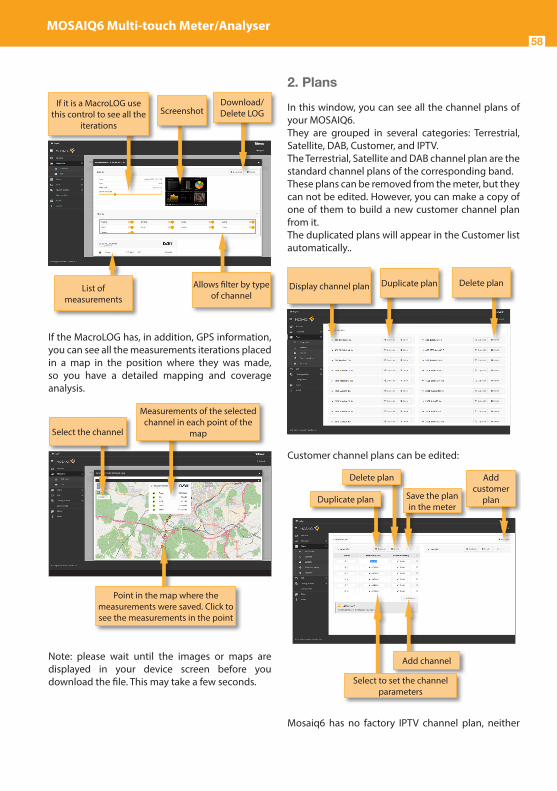
MOSAIQ6 Multi-touch Meter/Analyser58
2. Plans
In this window, you can see all the channel plans of your MOSAIQ6.They are grouped in several categories: Terrestrial, Satellite, DAB, Customer, and IPTV.The Terrestrial, Satellite and DAB channel plan are the standard channel plans of the corresponding band.These plans can be removed from the meter, but they can not be edited. However, you can make a copy of one of them to build a new customer channel plan from it.The duplicated plans will appear in the Customer list automatically..
Customer channel plans can be edited:
Mosaiq6 has no factory IPTV channel plan, neither
Display channel plan Duplicate plan Delete plan
Duplicate plan
Delete plan Add customer
plan
Add channel
Select to set the channel parameters
Save the plan in the meter
If the MacroLOG has, in addition, GPS information, you can see all the measurements iterations placed in a map in the position where they was made, so you have a detailed mapping and coverage analysis.
Note: please wait until the images or maps are displayed in your device screen before you download the file. This may take a few seconds.
If it is a MacroLOG use this control to see all the
iterations
Screenshot
List of measurements
Download/Delete LOG
Allows filter by type of channel
Select the channel
Measurements of the selected channel in each point of the
map
Point in the map where the measurements were saved. Click to see the measurements in the point

EN
59
FM plan. The user must create his own IPTV or FM channel plans. To create a new channel plan, click on the Add button. As you can see in the image below, you must select the type of channel plan: terrestrial, satellite, FM, DAB or IPTV:
You can add the IPTV channels one by one, or importing it from a .m3u file.A .m3u file is a plain text file that specifies the locations of one or more media files. Each media file must have the following structure: #EXTINF:-1,Das Erste HD rtp://@239.228.245.1:10000 rtp://@239.228.245.58:10000
Each media file must begin with the “#EXTINF:” label.“-1” indicates that it is a streaming file.“,” indicated that the next field is the channel name (in ths case Das Erste HD) . If there is no name for a channel, a default name will be assigned.At last it must appear the protocol and the address of the source. MOSAIQ6 only admits udp and rtp protocols.If a channel does not meet some of these specifications, it will not be included in the plan.
When the user select to import an IPTV channel plan from a .m3u file, the web app will ask you to select the file:
In this section, the user can also update the channel plans to the latest version saved in our server.
The application also allows to configure the channel plans according to the geographic area you will use the meter.
Display to see the channels
Save the channel plan in the meter
Duplicate plan
Delete planAdd new channel
IPTV channel parameters
Save the plan in the meter
Import IPTV channel plan from
.m3u file

MOSAIQ6 Multi-touch Meter/Analyser60
The user can select the channel plans using the feature Repository. In this window you can see all the channel plan grouped by zones.
You can also upload to your meter the channel plans of a geographical zone automatically. To do that use the feature Set zone. In this window you can see a map of the world, and you can select the area where you will use the meter by clicking on it. With this and considering the language selected in your meter, the MOSAIQ6 will select automatically the channel plans both in terrestrial and satellite bands.
Display to see the channels
Select the plans you wanto to save in your meter
Save the channel plan in the meter
Click on the area where you will use your meter
3. SCR
In this window, you can setup the multiswitches. The Mosaiq6 includes a list of multiswitches by default, but you can add more or edit any of the existing ones.
4. Quality profiles
Using the web application you can add new quality profiles. The MOSAIQ6 has two predefined quality profiles (head-end and outlet) that can not be edited, but they can be duplicated. The duplicated quality profiles are saved in the custom quality profiles, and the custom quality profiles can be edited.
Duplicate multiswitch
Select the parameters to edit them
Add new multiswitch
Delete multiswitchSave
multiswitch in the meter
Display to see all the values
Duplicate quality profile
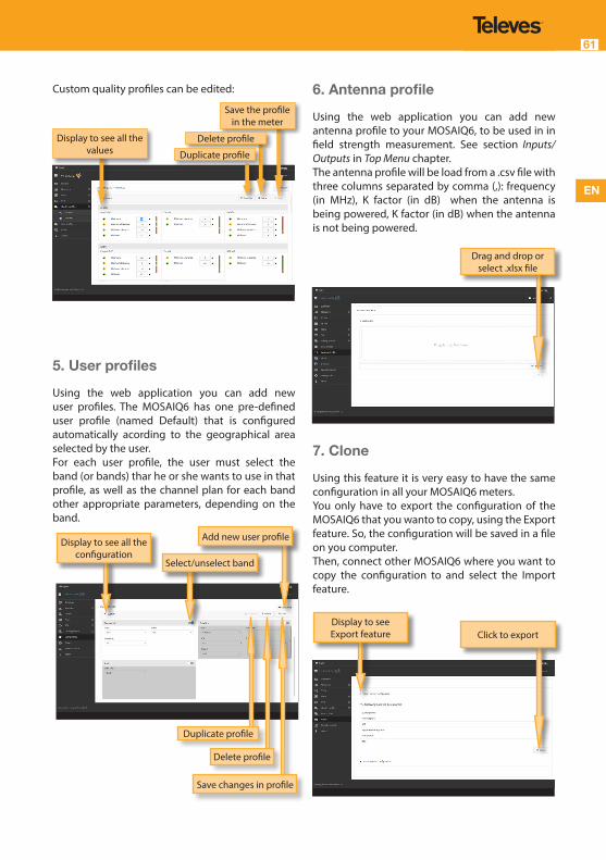
EN
61
Custom quality profiles can be edited:
5. User profiles
Using the web application you can add new user profiles. The MOSAIQ6 has one pre-defined user profile (named Default) that is configured automatically acording to the geographical area selected by the user.For each user profile, the user must select the band (or bands) thar he or she wants to use in that profile, as well as the channel plan for each band other appropriate parameters, depending on the band.
Display to see all the values
Save the profile in the meter
Delete profile
Duplicate profile
Display to see all the configuration
Add new user profile
Select/unselect band
Save changes in profile
Delete profile
Duplicate profile
6. Antenna profile
Using the web application you can add new antenna profile to your MOSAIQ6, to be used in in field strength measurement. See section Inputs/Outputs in Top Menu chapter.The antenna profile will be load from a .csv file with three columns separated by comma (,): frequency (in MHz), K factor (in dB) when the antenna is being powered, K factor (in dB) when the antenna is not being powered.
7. Clone
Using this feature it is very easy to have the same configuration in all your MOSAIQ6 meters.You only have to export the configuration of the MOSAIQ6 that you wanto to copy, using the Export feature. So, the configuration will be saved in a file on you computer.Then, connect other MOSAIQ6 where you want to copy the configuration to and select the Import feature.
Drag and drop or select .xlsx file
Display to see Export feature Click to export

MOSAIQ6 Multi-touch Meter/Analyser62
8. Licenses
Please contact the agents of our comercial network to purchase the license you wisht at any moment.You will receive an e-mail with an attached file that you must save in yur computer.Then select this feature to activate the license by dragging the file into the corresponding box that is shown on the screen, or find the file in your computer.Finally click on the Update button, the license will be activated in your MOSAIQ6.
9. Remote control
Using this feature you can control your MOSAIQ6 remotely. For this to work, it is necessary that the MOSAIQ6 and the computer are connected to the same LAN.To access to this feature you must enter the password admin in the right top part of the window. Then you will see the screen of the MOSAIQ6 in your computer:
Using the mouse you can control the MOSAIQ6 as with the hands, except the pinch/spread gestures.
10. Configuration
This feature allows you to restore the factory settings of your MOSAIQ6.When you do that, all the measurements, TS recordings, channel plans, quelity and user profiles stored in your meter will be deleted.
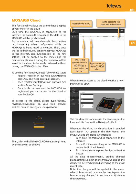
EN
63
MOSAIQ6 CloudThis functionality allows the user to have a replica of your meter in the cloud.Each time the MOSAIQ6 is connected to the internet, the data in the cloud and the data in the MOSAIQ6 will be synchronized.So, the user can add new channels plans, profiles, or change any other configuration while the MOSAIQ6 is being used to measure. Then, once the job is finished, you can connect your MOSAIQ6 to the internet, and automatically all the new settings will be applied to the meter, and the measurements saved during the workday will be saved in the cloud to be easily reviewed without having the MOSAIQ6 in the office.
To use this functionality, please follow these steps:• Register yourself in our web (www.televes.
com). You only need an e-mail account. • Then register your MOSAIQ6 in our web (See
section Before Starting)• Once both the user and the MOSAIQ6 are
registered, you can access to the cloud of your MOSAIQ6
To access to the cloud, please type “https://mycloud.televes.com” on your web browser address bar, and enter your user/password:
Then, a list with all the MOSAIQ6 meters registered by the user will be shown:
When the user access to the cloud website, a new page will be open:
The cloud website operates in the same way as the local website (see section Web Application).
Whenever the cloud synchronization is enabled (see section 1.4.- Update in the Main Menu) , the MOSAIQ6 and the cloud synchronizes:• Each time the MOSAIQ6 is connected to the
internet• Every 60 minutes (as long as the MOSAIQ6 is
connected to the internet)• Each time the user taps on the Syncronization
buttonAll the data (measurements, profiles, channel plans, settings...), both on the MOSAIQ6 and on the cloud, will be synchronized attending to the most recent date.Note: the changes will be applied to the meter when it is rebooted, or when the user taps on the button “Apply changes” in section 1.4.- Update in the Main Menu.
Hides/Shows menuTap to access to the
device cloud website
The icon is green when the
MOSAIQ6 is connected to the
internet
Type to change de MOSAIQ6
alias
MOSAIQ6 Multi-touch Meter/Analyser64
Error messagesLOW BATTERYIndicates that the battery is about to finish. The battery icon is red now. It is recommended to connect the meter to the external power source.
LOW BATTERYShutting down Some time after the LOW BATTERY message appears (time varies depending on the functions used), it will appear this message. If the meter is not connected to the external power source, it will switch off.
BAD POWERUnplug power source This message appears when the meter is connected to an external power source that does not supply it the right power. Please, use only the power source provided with the Mosaiq6.
SHORT-CIRCUITCheck installation This message appears when the meter detects a short-circuit at the RF input. It is recommended to check the installation to find out why the short circuit is produced.
DC OUTPUT LIMIT EXCEEDSwitch DC OUTPUT off This message appears when the meter detects an excessive consumption from the device that is being powered. It is recommended to turn off the powering feature of the MOSAIQ6.
DC AT RF INPUTCheck installationThis message appears when the meter detects DC at the RF input that is not generated by the MOSAIQ6. It is recommended to check the installation.
Maintenance
Always disconnect the unit before cleaning. Use only a mild solution of detergent and water applied with a soft damp cloth. Dry thoroughly before use.
Do not use aromatic hydrocarbons or chlorinated solvents. These products may damage the unit.
Do not use alcohol or alcohol based products on the front panel, especially the display.
These products may damage the unit.

EN
65
Technical supportFor any questions, contact Technical Support at
www.televes.com
Before contacting Technical Support for repair, read the manual to ensure proper use and attempt to RESET the unit to clear any problems.
Repair service
Do not return the unit without first contacting Televes Technical Support.
If the unit needs to be returned, Televes will arrange for free shipping. The unit will need to be appropriately packed for shipping.
In compliance with IATA Regulations, when using our shipping service follow these instructions:
• Label the package.
• The equipment should fit as snugly as possible in the box. It is recommended to use the original packing materials.
• Attach the precaution label to the package.
��������
����������
������������������������������������������
��������������������������������� �������
�� ��������� ���
Failure to comply with these shipping requirements may result in the shipping agent rejecting the package.
Warranty Televes warrants, only to the original Purchaser, for a period of one (1) year from the date of original purchase, unless otherwise specified.
For the battery, due to the nature of the product, the warranty period is six (6) months.
Keep the purchase invoice to determine the warranty start date.
During the warranty period, Televes S.A. assumes any defect in materials or workmanship.
This warranty excludes any inoperability resulting from improper use, wear, service or repair performed by any third party not authorized, catastrophes or any cause unrelated to Televes S.A.

MOSAIQ6 Multi-touch Meter/Analyser66
DECLARACIÓN DE CONFORMIDAD DECLARATION OF CONFORMITY DECLARAÇÃO DE CONFORMIDADE DECLARATION DE CONFORMITE DICHIARAZIONE DI CONFORMITÀ DEKLARACJA ZGODNOŚCI
KONFORMITÄTSERKLÄRUNG ΠΙΣΤΟΠΟΙΗΤΙΚΟ ΣΥΜΜΟΡΦΩΣΗΣ FÖRSÄKRAN OM ÖVERENSSTÄMMELSE ДЕКЛАРАЦИЯ СООТВЕТСТВИЯ www.doc.televes.com ةقباطملا نايب

596101_596111_1.38_EN
Related Documents