Paper ID #28404 Refrigeration Cycle Educational Training Unit Development Dr. Maher Shehadi, Purdue Polytechnic Institute Dr. Shehadi is an Assistant Professor in the School of Engineering Technology at Purdue University. His academic experience has focused on learning and discovery in areas related to HVAC, indoor air quality, human thermal comfort, and energy conservation. While working in industry, he oversaw maintenance and management programs for various facilities including industrial plants, high rise residential and com- mercial buildings, energy audits and condition surveys for various mechanical and electrical and systems. He has conducted several projects to reduce CO2 fingerprint of buildings. His current work focuses on sustainable energy resources. c American Society for Engineering Education, 2020

Welcome message from author
This document is posted to help you gain knowledge. Please leave a comment to let me know what you think about it! Share it to your friends and learn new things together.
Transcript
Paper ID #28404
Refrigeration Cycle Educational Training Unit Development
Dr. Maher Shehadi, Purdue Polytechnic Institute
Dr. Shehadi is an Assistant Professor in the School of Engineering Technology at Purdue University. Hisacademic experience has focused on learning and discovery in areas related to HVAC, indoor air quality,human thermal comfort, and energy conservation. While working in industry, he oversaw maintenanceand management programs for various facilities including industrial plants, high rise residential and com-mercial buildings, energy audits and condition surveys for various mechanical and electrical and systems.He has conducted several projects to reduce CO2 fingerprint of buildings. His current work focuses onsustainable energy resources.
c©American Society for Engineering Education, 2020

Refrigeration Cycle Educational Training Unit Development
ABSTRACT
Refrigeration cycles are vital in today’s industrial and domestic life. Many applications including, but not limited to, residential air conditioning, shopping malls heating ventilation and air conditioning, and food and liquid refrigeration operate with refrigeration cycles. Students graduating with a mechanical engineering technology degree, such as associate, bachelor, or technical certificate need to have sufficient hands on experience with refrigeration cycle operation, trouble shooting, analysis and optimization.
An ASHRAE grant was awarded to modify a 12,000 BTU “TRIPP LITE” portable air-conditioning unit to setup a teaching laboratory experiment related to refrigeration cycles. The experiment was equipped with pressure and temperature sensing apparatus to help in analyzing, troubleshooting, and operating various refrigeration cycles
Thermodynamics and heat transfer principles are applied to evaluate cycle efficiency, compressor power, and temperature rise and drop though the evaporator and condenser. The relative working pressures are plotted on pressure-enthalpy diagram of R410A refrigerant which was used inside the refrigeration cycle. Experimental informational outcomes will help students to understand theoretical principles in an experimental environment besides learning how to use some other equipment such as sensors, pressure gages, mass flow meter, and multi-meters. This paper presents thermodynamic refrigeration equations, experimental setup and a case study with different input variables.
Students in different courses would apply thermodynamics and heat transfer principles to evaluate cycle efficiency, compressor power, and temperature rise and drop across the evaporator, condenser, compressor, and throttling valve. The experiment not only will help the students visualize the cycle on a P-h diagram but will also provide an opportunity to compare the theoretical values, such as power consumed, EER, COP of the cycle, to the actual values obtained by the running unit.
INTRODUCTION
Experimental design and testing of theoretical aspects in a lab oriented class is an effective approach used in technological applications and research and development. Some applications

include design and development of electric motors [1], medical devices, and technological processes [2-4], aircraft engines [5] and bike-frames [6].
Thermodynamic refrigeration cycles are widely used in many applications such as air conditioning systems, thermal storage systems, supermarkets, district cooling, industrial refrigeration, domestic fridges, bottle coolers, heat pumps, and automotive air conditioning systems. The basic elements of a refrigeration cycle are shown in Figure 1 while operating under summer conditions providing cold air to an enclosed space and rejecting hot air to the surrounding environment. This cycle could be reversed to supply hot air to the same enclosed space during winter season when hot air is required. The later is called a heat pump.
Figure 1. Refrigeration cycle basic elements operating in summer season providing cool air to an enclosed space
Relation between the cycle performance and air temperatures going through the evaporator and condenser is of interest for designers and application engineers when selecting a cooling unit for a specific place. Changing a single control parameter while keeping the others fixed is usually used although it does not provide the most accurate results. This one-factor approach usually provides advantages only under specific condition [7].
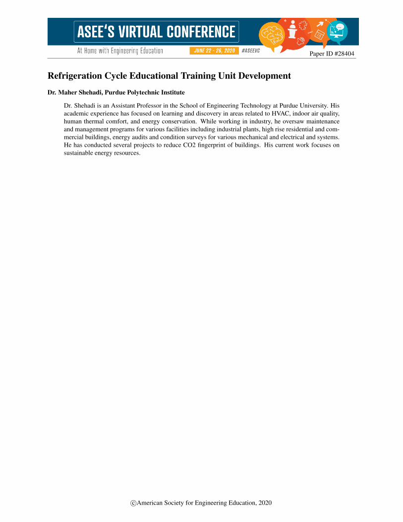
The different thermodynamic properties of the refrigerant operating the cycle are usually plotted on a P-h (pressure-enthalpy), P-T (pressure-temperature) diagrams and charts or T-s (temperature-entropy) as shown in Figure 2. Students usually work an in-class example during their course work and most of the cycles that they analyze are theoretical.
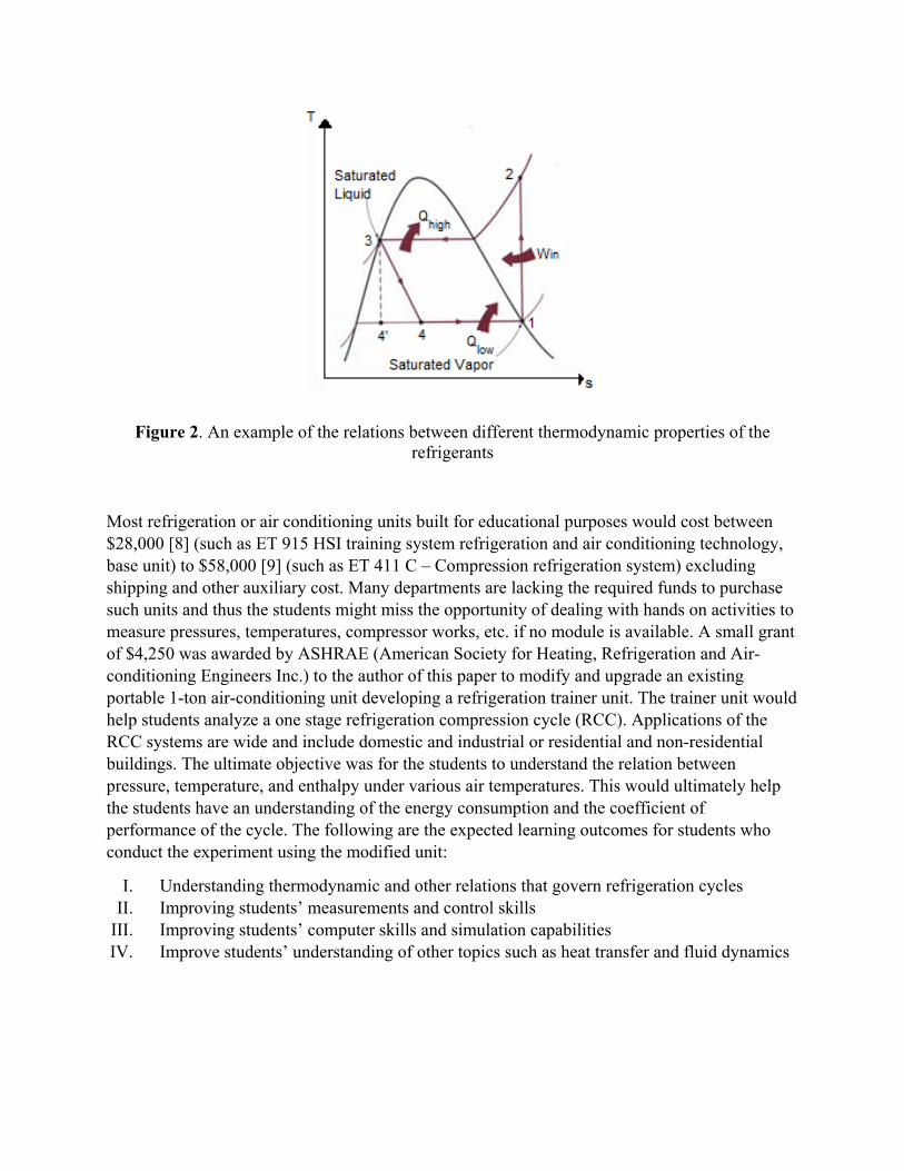
Figure 2. An example of the relations between different thermodynamic properties of the refrigerants
Most refrigeration or air conditioning units built for educational purposes would cost between $28,000 [8] (such as ET 915 HSI training system refrigeration and air conditioning technology, base unit) to $58,000 [9] (such as ET 411 C – Compression refrigeration system) excluding shipping and other auxiliary cost. Many departments are lacking the required funds to purchase such units and thus the students might miss the opportunity of dealing with hands on activities to measure pressures, temperatures, compressor works, etc. if no module is available. A small grant of $4,250 was awarded by ASHRAE (American Society for Heating, Refrigeration and Air-conditioning Engineers Inc.) to the author of this paper to modify and upgrade an existing portable 1-ton air-conditioning unit developing a refrigeration trainer unit. The trainer unit would help students analyze a one stage refrigeration compression cycle (RCC). Applications of the RCC systems are wide and include domestic and industrial or residential and non-residential buildings. The ultimate objective was for the students to understand the relation between pressure, temperature, and enthalpy under various air temperatures. This would ultimately help the students have an understanding of the energy consumption and the coefficient of performance of the cycle. The following are the expected learning outcomes for students who conduct the experiment using the modified unit:
I. Understanding thermodynamic and other relations that govern refrigeration cycles II. Improving students’ measurements and control skills
III. Improving students’ computer skills and simulation capabilities IV. Improve students’ understanding of other topics such as heat transfer and fluid dynamics

EXPERIMENTAL SETUP
A portable air-conditioning unit with a 12000 Btu capacity, brand Tripp Lite and model SRCOOL12K was used as the testing unit as shown in Figure 3. The following are the brands and models for the main units inside the AC unit: compressor model is LR3 – KA-C115ABBC-E (115 V – 50 A), fans are LIAN DA, Evaporator is MD781AL and condenser is MD711AL.
Figure 3. Portable AC unit modified to build the air-conditioning trainer
Seven thermocouples were initially installed after removing the outer shell of the unit (Figure 4a and 4b). The thermocouples were connected into a 24-channel omega thermocouple temperature reader in Figure 4c.
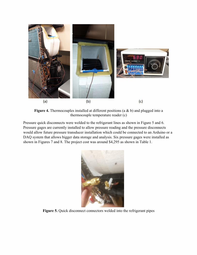
Figure 4. Thermocouples installed at different positions (a & b) and plugged into a thermocouple temperature reader (c)
Pressure quick disconnects were welded to the refrigerant lines as shown in Figure 5 and 6. Pressure gages are currently installed to allow pressure reading and the pressure disconnects would allow future pressure transducer installation which could be connected to an Arduino or a DAQ system that allows bigger data storage and analysis. Six pressure gages were installed as shown in Figures 7 and 8. The project cost was around $4,295 as shown in Table 1.
Figure 5. Quick disconnect connectors welded into the refrigerant pipes

Figure 6. Pressure gage with quick disconnect welded into its inlet connection
Figure 7. Pressure gage locations with reference indexing to be used in the analysis equations
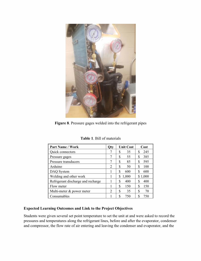
Figure 8. Pressure gages welded into the refrigerant pipes
Table 1. Bill of materials
Part Name / Work Qty Unit Cost Cost Quick connectors 7 $ 35 $ 245 Pressure gages 7 $ 55 $ 385 Pressure transducers 7 $ 85 $ 595 Arduino 2 $ 50 $ 100 DAQ System 1 $ 600 $ 600 Welding and other work 1 $ 1,000 $ 1,000 Refrigerant discharge and recharge 1 $ 400 $ 400 Flow meter 1 $ 150 $ 150 Multi-meter & power meter 2 $ 35 $ 70
Consumables 1 $ 750 $ 750
Expected Learning Outcomes and Link to the Project Objectives
Students were given several set point temperature to set the unit at and were asked to record the pressures and temperatures along the refrigerant lines, before and after the evaporator, condenser and compressor, the flow rate of air entering and leaving the condenser and evaporator, and the

power consumed by the compressor and the unit. The following are more specific learning outcomes categorized as per the objectives listed in the “Introduction” section of this paper.
1) Objective # I: Understanding thermodynamic and other relations that govern refrigeration cycles
a. Reading pressures and temperatures b. Plotting the points on p-h diagram c. Estimating the cooling load by applying energy balance across the evaporator
q m C , T T 𝜌 Q C , ∆T (1) where qevp is the evaporator heat transfer rate, m is the refrigerant mass flow rate, C is the specific heat, T T is the temperature difference across the evaporator as
defined in Figure 7, 𝜌 is the density of air, Q is the volumetric flow rate of air entering and leaving the evaporator, and ∆T is the temperature difference of air across the evaporator. The later temperature difference was measured by taking the average of several temperature readings across the evaporator inlet surface and by measuring the temperature at the air supply outlet as shown in Figure 4b. The volumetric flow rate was measured by taking multiple air speed measurements using a digital anemometer and multiplying it by the corresponding area as shown in equation (2).
Q A. V (2)
where A is the cross sectional area of the evaporator unit or the supply air duct and V is the velocity. Since the velocity changes between the center of the evaporator cross section and the cross section, it was recommended to measured it at different points and then average the readings (meets Objective II as well: Measurements Skills)
d. Evaluating the coefficient of performance COP of the cycle using equation (3).
COP (3)
where Win is the total power consumed by the unit and is measured using a power meter plugged directly to the power inlet or using a multi-meter and measuring the voltage and current at different points (meets Objective II as well: Measurements Skills)

2) Objective # II: Improving students’ measurements and control skills a. Measuring pressures and temperatures and installing pressure transducers to be all
connected to an Arduino and storing the data. b. Measuring voltage, current and power at different points. c. Estimating the airflow rate entering and leaving each of the condenser and
evaporator.
3) Objective # III: Improving students’ computer skills and simulation capabilities a. Plotting the COP versus load and set temperature: Simulation can be then done by
changing the evaporator air outlet and inlet temperatures and checking on the COP change of the cycle. This would give the students an understanding of the cycle efficiency. At the same time, the students would evaluate the work into the compressor, the load removed by the evaporator, the load rejected by the condenser and enthalpy drop in the capillary tube using the P-h diagram.
b. Assigning projects to connect the thermocouples into ARDUINO unit and connecting it to a computer to download the data.
4) Objective # IV: Improve students’ understanding of other topics such as heat transfer a. Reading the enthalpies from P-h diagram b. Repeating the above procedures while setting the unit set temperature to different
set points and comparing the COP and making observations and conclusions. c. Setting the unit to a higher set temperature than the actual surrounding
temperature while in cooling mode and analyzing the performance of the compressor.
d. Applying heat balance for the compressor, evaporator, and condenser. i. Evaporator: reading the enthalpies h7 and h6 and comparing the answer
using equation (4) to that in equation (1), the refrigerant mass flow rate would be determined. The State subscripts for each enthalpy is as indicated in Figure 7. q m h h (4)
ii. Compressor: Reading the two enthalpies before and after the compressor from the plotted p-h diagram and using it in equation (5), the work done by the compressor could be determined. Subtracting the total power from the compressor power would indicate the remaining power being consumed by the fans and other auxiliary components.
Wcompressor = m (h2 – h1) (5)

iii. Fans: using a multi-meter, the voltage, current and power across each auxiliary fan could be measured. A total power consumption could be done using the measured power for each fan and for that by the compressor and compared to the power being pulled by the unit using a power meter plugged to the power inlet into the AC unit main power cord.
iv. Condenser: similar to the evaporator, an energy balance across the condenser could be done as shown in equations (6) and (7).
q m C , T T 𝜌 Q , C , ∆T , (6)
q m (h2 – h1) (7)
where Q , is the air volumetric flow rate passing through the condenser unit or leaving through the exhaust out from the unit and ∆T , is the air temperature different between the inlet at the condenser face and the exhaust port from the unit.

Numerical Example
The following data was recorded using the modified unit. Voltage and amperes across different components would need to be measured and compared to the system measurements for further analysis.
Compressor Measure
Volumetric Flow Rate 0.12 m3/hr
Tem
pera
ture
s
T1 62.8 F Inlet Pressure (P1) 180 psi T2 150 F Outlet Pressure (P2) 230 psi T3 120 F Inlet Temperature (T1) 62.8 F T4 72.1 F Outlet Temperature (T2) 150 F T5 75.2 F
Watts T6 47.6 F Amp (A) T7 53.2 F
Pre
ssur
es P1 180 psi
Evaporator P2 230 psi Ref. Flow Rate 0.12 m3/hr P4 230 psi Inlet Pressure (P6) 180 psi P6 180 psi Inlet Temperature (T6) 47.6 F
Outlet Temperature (T7) 53.2 F System
volts Air Flow Rate 372 CFM Amps
Fan V 520 Watt Amp (A)
Condenser
Ref. Flow Rate 0.12 m3/hr
Outlet Pressure (P4) 230 psi
Inlet Temperature (T3) 120 F
Outlet Temperature (T4) 72.1 F
Air Flow Rate 418 CFM
Fan V
Amp (A)
After measuring the different temperatures and pressures, the enthalpy at different states were read and recorded in Table 2.
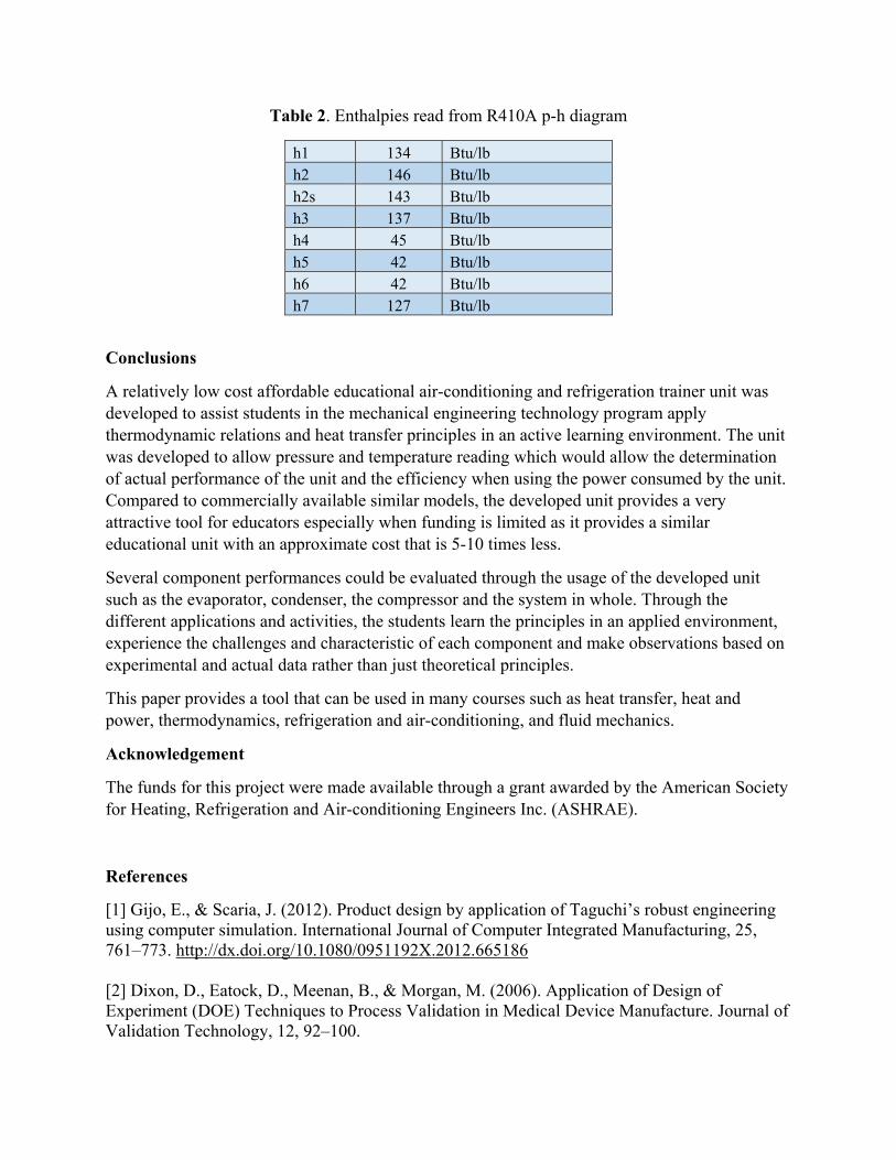
Table 2. Enthalpies read from R410A p-h diagram
h1 134 Btu/lb h2 146 Btu/lb h2s 143 Btu/lb h3 137 Btu/lb h4 45 Btu/lb h5 42 Btu/lb h6 42 Btu/lb h7 127 Btu/lb
Conclusions
A relatively low cost affordable educational air-conditioning and refrigeration trainer unit was developed to assist students in the mechanical engineering technology program apply thermodynamic relations and heat transfer principles in an active learning environment. The unit was developed to allow pressure and temperature reading which would allow the determination of actual performance of the unit and the efficiency when using the power consumed by the unit. Compared to commercially available similar models, the developed unit provides a very attractive tool for educators especially when funding is limited as it provides a similar educational unit with an approximate cost that is 5-10 times less.
Several component performances could be evaluated through the usage of the developed unit such as the evaporator, condenser, the compressor and the system in whole. Through the different applications and activities, the students learn the principles in an applied environment, experience the challenges and characteristic of each component and make observations based on experimental and actual data rather than just theoretical principles.
This paper provides a tool that can be used in many courses such as heat transfer, heat and power, thermodynamics, refrigeration and air-conditioning, and fluid mechanics.
Acknowledgement
The funds for this project were made available through a grant awarded by the American Society for Heating, Refrigeration and Air-conditioning Engineers Inc. (ASHRAE).
References
[1] Gijo, E., & Scaria, J. (2012). Product design by application of Taguchi’s robust engineering using computer simulation. International Journal of Computer Integrated Manufacturing, 25, 761–773. http://dx.doi.org/10.1080/0951192X.2012.665186 [2] Dixon, D., Eatock, D., Meenan, B., & Morgan, M. (2006). Application of Design of Experiment (DOE) Techniques to Process Validation in Medical Device Manufacture. Journal of Validation Technology, 12, 92–100.

[3] Steinberg, D., & Bursztyn, D. (2010). Response surface methodology in biotechnology. Quality Engineering, 22, 78–87. http://dx.doi.org/10.1080/08982110903510388 [4] Vlachogiannis, J. (2003). Taguchi's technique: An effective method for improving X-ray medical radiographic screen performance. Proceedings of the Institution of Mechanical Engineers, Part H: Journal of Engineering in Medicine, 217, 375–384. http://dx.doi.org/10.1243/095441103770802540 [5] Tappeta, R., Nagendra, S., & Renaud, J. (1999). A multidisciplinary design optimization approach for high temperature aircraft engine components. Structural Optimization, 18, 134–145. http://dx.doi.org/10.1007/BF01195988 [6] Jeang, A., Liang, F., & Chung, C. (2008). Robust product development for multiple quality characteristics using computer experiments and an optimization technique. International Journal of Production Research, 46, 3415–3439. http://dx.doi.org/10.1080/00207540601139963 [7] Frey, D., & Wang, H. (2006). Adaptive one-factor-at-a-time experimentation and expected value of improvement. Technometrics, 48, 418–431. http://dx.doi.org/10.1198/004017006000000075 [8] Gunt Hamburg. ET 915 HIS training refrigeration and air conditioning technology, base unit. Accessed 2016. https://www.gunt.de/en/products/refrigeration/fundamentals-of-refrigeration/hsi-training-system-refrigeration-and-air-conditioning-technology-base-unit/061.91500/et915/glct-1:pa-148:ca-714:pr-302 [9] Gunt Hamburg. ET 411C Compression Refrigeration System. Accessed 2016. https://www.gunt.de/en/products/refrigeration/fundamentals-of-refrigeration/compression-refrigeration-system/061.411C0/et411c/glct-1:pa-148:ca-714:pr-206
Authors’ Bio:
Dr. Shehadi is an Assistant Professor in the School of Engineering Technology at Purdue University. His academic experience has focused on learning and discovery in areas related to HVAC, indoor air quality, human thermal comfort, and energy conservation. While working in industry, he oversaw maintenance and management programs for various facilities including industrial plants, high rise residential and commercial buildings, energy audits and condition surveys for various mechanical and electrical and systems. He has conducted several projects to reduce CO2 fingerprint of buildings. His current work focuses on sustainable energy resources.
Related Documents