1 REFLECTIVE COMMUNICATIONS FRAMEWORK: AN APPROACH TO RAPID DEPLOYMENT OF COMMUNICATIONS ARCHITECTURES IN DISTRIBUTED SYSTEMS By JEAN-FRANÇOIS A. KAMATH A DISSERTATION PRESENTED TO THE GRADUATE SCHOOL OF THE UNIVERSITY OF FLORIDA IN PARTIAL FULFILLMENT OF THE REQUIREMENTS FOR THE DEGREE OF DOCTOR OF PHILOSOPHY UNIVERSITY OF FLORIDA 2009

Welcome message from author
This document is posted to help you gain knowledge. Please leave a comment to let me know what you think about it! Share it to your friends and learn new things together.
Transcript

1
REFLECTIVE COMMUNICATIONS FRAMEWORK: AN APPROACH TO RAPID DEPLOYMENT OF COMMUNICATIONS ARCHITECTURES
IN DISTRIBUTED SYSTEMS
By
JEAN-FRANÇOIS A. KAMATH
A DISSERTATION PRESENTED TO THE GRADUATE SCHOOL OF THE UNIVERSITY OF FLORIDA IN PARTIAL FULFILLMENT
OF THE REQUIREMENTS FOR THE DEGREE OF DOCTOR OF PHILOSOPHY
UNIVERSITY OF FLORIDA
2009

2
© 2009 Jean-François A. Kamath

3
ACKNOWLEDGEMENTS
I would like to thank Dr. Carl Crane for his support and guidance throughout my graduate
education. He has been an excellent advisor and mentor for many years. I would also like to
thank Dr. Douglas D. Dankel in CISE at the University of Florida for his help. Dr. John K.
Schueller (co-chair), Dr. Gloria Wiens, Dr. Gary K. Matthew, and Dr. A. Antonio Arroyo have
provided great support over the years. The Air Force Research Laboratory, at Tyndall Air Force
Base, is responsible for making this project possible.
It is important to also acknowledge one colleague and close friend in particular at the
Center for Intelligent Machines and Robotics; Steven J. Velat has been an invaluable resource
and partner in development of this project. His comments and ideas throughout are a major
reason JAUS .NET has gotten where it is today.

4
TABLE OF CONTENTS page
ACKNOWLEDGEMENTS ................................................................................................................. 3
LIST OF TABLES................................................................................................................................ 7
LIST OF FIGURES .............................................................................................................................. 8
ABSTRACT ........................................................................................................................................ 10
CHAPTER
1 INTRODUCTION....................................................................................................................... 12
Motivation.................................................................................................................................... 12 Research Solution ........................................................................................................................ 12
2 BACKGROUND ......................................................................................................................... 16
Considerations for Distributed Systems .................................................................................... 18 Web-Based Communications ..................................................................................................... 20 Example Architectures ................................................................................................................ 23
Microsoft Robotics Studio .................................................................................................. 23 Windows Communication Foundation ............................................................................... 26
Joint Architecture for Unmanned Systems ................................................................................ 27
3 APPROACH ................................................................................................................................ 30
Overview ...................................................................................................................................... 30 Primary Architecture ........................................................................................................... 31 Data Flow and Logic ........................................................................................................... 32
Reflection and Dynamic Reconfiguration ................................................................................. 34 Communications Interface .......................................................................................................... 37 Message Handler ......................................................................................................................... 41
Dynamic Message Set ......................................................................................................... 43 Interpreter ............................................................................................................................. 44 Message Routing.................................................................................................................. 46
Generalized Serialization and Message Structuring ................................................................. 48 Recursive Serialization/Deserialization ............................................................................. 49
Packer design ................................................................................................................ 50 Targeted implementation example: BytePacker......................................................... 54
Custom Data Types ............................................................................................................. 58 Field attribute................................................................................................................ 60 Processing method attributes ....................................................................................... 62 Inheritance .................................................................................................................... 64
Final Comments on Approach .................................................................................................... 65
5
4 JAUS .NET .................................................................................................................................. 67
Overview of the JAUS Reference Architecture ........................................................................ 67 Node Manager Interface / JausComponent Object ................................................................... 69
Messaging............................................................................................................................. 70 State Machine....................................................................................................................... 72 Application Integration........................................................................................................ 72
Design and Implementation of the JAUS Message Set ............................................................ 73 General Message Format ..................................................................................................... 73 Custom Attributes and the Message Handler ..................................................................... 75 Raw Messages ...................................................................................................................... 76 Example Message Definitions ............................................................................................ 77
JausHeader .................................................................................................................... 78 ReportGlobalPose......................................................................................................... 79 Service connections ...................................................................................................... 80
Implementation of the JAUS Message Handler ........................................................................ 81 Interface Message Handler & Message Set ............................................................................... 85 Service Connection Manager ..................................................................................................... 86 Final Comments .......................................................................................................................... 88
5 PERFORMANCE OPTIMIZATIONS & DESIGN CHALLENGES ..................................... 90
Inner Working of .NET ............................................................................................................... 90 Reflection ............................................................................................................................. 91 Methods and Microsoft Intermediate Language ................................................................ 92
Reflective Optimizations ............................................................................................................ 95 Storing Message Structure .................................................................................................. 95 Dynamic Methods ................................................................................................................ 96
BytePacker Optimizations .......................................................................................................... 99
6 RESULTS AND CONCLUSIONS .......................................................................................... 101
Major Features ........................................................................................................................... 101 Performance ............................................................................................................................... 103 Final Comments ........................................................................................................................ 106
APPENDIX
A REFLECTIVE COMMUNICATIONS FRAMEWORK PACKER DOCUMENTATION ............................................................................................................... 109
Introduction ............................................................................................................................... 109 Required Overrides and Design Considerations ..................................................................... 109
PackNew............................................................................................................................. 111 Deserialization Methods .................................................................................................... 113
FromSourceType ........................................................................................................ 114 FromSourceObject ..................................................................................................... 115
GetFinal .............................................................................................................................. 116
6
AddNewValue.................................................................................................................... 117 Internal Storage .................................................................................................................. 117 Final Comments ................................................................................................................. 118 Example Non-Serial Message Format and Packer .......................................................... 120
B JAUS .NET COMPONENT CREATION ............................................................................... 122
Introduction ............................................................................................................................... 122 JAUS .NET Overview .............................................................................................................. 122
Component Structure ......................................................................................................... 123 JausComponent .......................................................................................................... 124 Message handlers ....................................................................................................... 126 Message processors and message structure .............................................................. 129 State machine.............................................................................................................. 130 Service connections .................................................................................................... 131
Major Namespaces............................................................................................................. 132 Jaus.Nmi ..................................................................................................................... 133 Jaus.Nmi.Services. ..................................................................................................... 133 Jaus.Messages ............................................................................................................. 133 Jaus.InterfaceMessages .............................................................................................. 133 Rcf.Utilities.Threading .............................................................................................. 133
Example Components ............................................................................................................... 134 SimpleComponent ............................................................................................................. 134 ConsoleComponent ........................................................................................................... 138 GPoseProvider ................................................................................................................... 139
Custom messages ...................................................................................................................... 143 JausContents Attribute ...................................................................................................... 143 Serialization Attributes ...................................................................................................... 144
LIST OF REFERENCES ................................................................................................................. 146
BIOGRAPHICAL SKETCH ........................................................................................................... 149

7
LIST OF TABLES
Table page 6-1 Serialization performance of native vs. managed environments....................................... 105
8
LIST OF FIGURES
Figure page 2-1 Message arbitration layer in MSRS. Image taken from [Jackson 2007]. .......................... 25
2-2 Communications layer in MSRS. Image taken from [Jackson 2007]. ............................... 25
3-1 Relationship between RCF components and end user components. ................................... 31
3-2 Inbound data. .......................................................................................................................... 33
3-3 Outbound data. ....................................................................................................................... 33
3-4 Structure of a .NET assembly................................................................................................ 35
3-5 Communications interface structuring. ................................................................................. 38
3-6 Data types and send functionality for UDP com interface. ................................................. 39
3-7 Receive thread flowchart. ...................................................................................................... 40
3-8 Data structure for the message handler. ................................................................................ 42
3-9 Handler access of message library and processing methods. .............................................. 42
3-10 Data type hashtable update. ................................................................................................... 44
3-11 Serialization/Deserialization flowchart................................................................................. 51
3-12 Serialization process for member fields and special processing methods. ......................... 52
3-13 Deserialization process for member fields and processing methods. ................................. 52
3-14 Serialization of data in BytePacker class. ............................................................................. 57
3-15 Deserialization routines by simple data type and by pre-allocated type............................. 58
3-16 Memory layout of inherited messages. ................................................................................. 65
4-1 Overall layout of Node Manager Interface. .......................................................................... 70
4-2 Inheritance and structure of RawJausMessage. ................................................................... 76
4-3 Memory layout of JausHeader including optional header string. ...................................... 78
4-4 Send method for JAUS messages. ........................................................................................ 83
4-5 Deserialization of a JAUS message. ..................................................................................... 84

9
4-6 Message routing using the processor list. BeginInvoke is an ansynchronous invocation in .NET. ................................................................................................................ 85
5-1 Stack operations during method calls. .................................................................................. 93
6-1 Simplified speed testing for a JAUS message. ................................................................... 107
6-2 Simulated packing as performed by the message handler. ................................................ 107
6-3 Simulated unpacking operations. ........................................................................................ 108
A-1 Typical implementation for PackNew. ............................................................................... 111
A-2 FromSourceType layout. ...................................................................................................... 115
A-3 Targeted PackNew method. ................................................................................................. 119
A-4 Example message format. .................................................................................................... 120
A-5 Internal storage layout post-serialization. ........................................................................... 121
B-1 General component structure. .............................................................................................. 123
B-2 JausComponent inheritance and primary features. ............................................................ 124
B-3 JausMessage structure. ........................................................................................................ 129
B-4 States and state enumerations. ............................................................................................. 131
B-5 SimpleComponent form. ...................................................................................................... 135
B-6 ConsoleComponent user interface....................................................................................... 139
B-7 GPoseProvider main form................................................................................................... 140
B-8 PackableMember attribute members. ................................................................................. 144
10
Abstract of Dissertation Presented to the Graduate School of the University of Florida in Partial Fulfillment of the Requirements for the Degree of Doctor of Philosophy
REFLECTIVE COMMUNICATIONS FRAMEWORK:
AN APPROACH TO RAPID DEPLOYMENT OF COMMUNICATIONS ARCHITECTURES IN DISTRIBUTED SYSTEMS
By
Jean-François A. Kamath
April 2009 Chair: Carl Crane III Cochair: John K. Schueller Major: Mechanical Engineering
The Reflective Communications Framework (RCF) is a novel approach to distributed
system development that enables rapid deployment of a wide range of communications
architectures. It generalizes the core components common to most distributed systems and is
designed in a highly modular fashion. The RCF includes several key features:
• Generalized message structuring that is format independent. • Decoupling of the low-level communications from the high-level application logic. • Automated tracking and processing of the modular components. • Cross-platform compatibility. • Rapid application development.
Architectures developed with this framework are naturally event-driven and are capable of
dynamic reconfiguration. They can be easily modified and updated due to the modular design.
An implementation of the Joint Architecture for Unmanned Systems (JAUS) has been created
with this framework to demonstrate feasibility and to provide an example of how the components
interact.
A great focus has been placed on performance of the underlying framework. The result is
a generalized and highly flexible architecture that approaches the performance of native code in

11
many areas while still leveraging the conveniences of a managed, object-oriented environment.
This enables far more rapid and reliable application development than would be possible in many
existing systems. While the toolset that has been developed and demonstrated using the .NET
framework, the architectural design could easily be implemented in any environment that
supports similar features. The standardization of development tools represents a major
advancement in the creation of distributed systems.

12
CHAPTER 1 INTRODUCTION
Motivation
Modern developers face many challenges in the deployment of distributed systems such as
multi-processor robotic platforms. One of the major issues they face is how to implement
communications amongst the various modules. Communications architectures in distributed
systems tend to fall into two categories: compatibility driven and performance driven.
Compatibility driven architectures are geared towards enabling the widest range of environments
to easily exchange information while performance driven systems are more interesting in
optimizing the efficiency of data exchange.
While many architectures have been developed in both areas, compatibility driven systems
have become predominant for a number of reasons that will be discussed in the next section. As
a result, most tools for enabling communications have been targeted at these architectures while
generally ignoring performance targeted messaging. The lack of generally available tools makes
implementation of high-performance messaging difficult. This dissertation addresses some of
the main issues that hamper rapid deployment of communications in performance based
applications.
Research Solution
The communications framework in a distributed system requires three primary components
to function effectively. The first is the defined message set that is used by the applications to
represent information. In effect, this can be viewed as the high-level language in which the
applications talk. The second major component is the transport layer used to actually send the
data between modules. Many low-level communications protocols have been developed to meet
a wide variety of needs and often share little in common. The third component handles

13
arbitration, conversion, and interpretation of message data as its travels between the main
application level and the low-level communications sections. This component is critical for two
primary reasons. First, it is responsible for converting application meaningful data to a format
that can be transported and back. Without this, it would be nearly impossible to create human-
readable applications. Second, the arbitration aspect of the framework is used to determine
which parts of an application are given access to communications data. A close analogue to the
entire architecture would be the telephone system used daily. People communicate via a
common language that is used to represent various types of information. When a person speaks
into the telephone, his/her voice is converted into electrical signals that are routed by the
network. The network determines where the signals should be sent, and when they arrive at the
other end, are converted back into sounds that can be understood.
A Reflective Communications Framework (RCF) has been developed to tackle the major
hurdles to rapid deployment of a communications architecture while still providing a structured
and maintainable toolset. It utilizes a three tiered system:
• Generalized low-level transport that hides the specifics of the transport from the developer.
• Pre-processing and interpretation layer that deals with arbitration and data conversion.
• Highly customizable message representation that provides a high level of control of message structuring regardless of the low-level communications format.
These components are designed to interact through a set of interfaces and attributes that
allow easy reconfiguration of program behavior while maintaining tight control over the
structure of the communications framework. It operates on an event driven model to separate the
low-level functionality from the high-level application behavior while minimizing the amount of
specialized programming required.

14
A reflective programming model was chosen due to the inherent flexibility that can be
built into the application. Reflective programming is the ability of application components to
describe themselves and determine traits at runtime. As used in this project, reflection allows a
developer to define dynamically reconfigurable message sets that provide a great degree of
control over structuring as well as the ability to modify application behavior at runtime, all of
which can be accomplished with relatively little code overhead.
Aspects of the Reflective Communications Framework are similar to those used in
Microsoft Robotics Studio (MSRS), which is an attempt by Microsoft to provide a toolset for
rapidly deploying robotics systems using the .NET environment. The arbiters and message
structure in MSRS are attempts to provide an easy means for a developer to define application
behavior. However, all of the tools in the environment are meant only to be used in MSRS
services, effectively preventing communication with other non-MSRS applications. The
environment also lacks the flexibility to control exact message structure, fine-application
behavior, and even the exact low-level communications layer. The proprietary nature of MSRS
makes it too rigid for effective distributed system development. This is discussed in much
greater detail in the Background chapter.
The Reflective Communications Framework provides ease of application development
while also giving much greater control over exact program behavior and message structuring
with few limitations on communications format. With minimal effort on the users’ part, a
compact messaging architecture can be easily implemented while providing performance,
flexibility, and safety. Use of this framework has the added benefit of creating a highly
maintainable communications system with a highly modular design that can be modified rapidly
and implemented in a wide range of applications.

15
Throughout this text, it will be necessary to provide code examples to help explain the
logic and usage of many components of the RCF. Since the framework was developed entirely
in C#, the examples will be presented as a mixture of C# and Backus-Naur Form (BNF) code to
provide a compact and complete description. It is assumed that readers are familiar with an
object oriented language such as C++ or Java and have a basic understanding of BNF notation.
However, one important deviation from standard BNF notation is the use of ‘$’ to indicate
optional elements rather than the standard square brackets. This is to avoid confusion when
reading the mixed C# code that naturally uses square brackets. Appendix A provides more
detailed examples of how to use the RCF.

16
CHAPTER 2 BACKGROUND
Application complexity has increased dramatically over the years, requiring the
development of higher level languages and new approaches solve the programming challenges.
A radical shift in design was the conception of distributed systems to perform complex or
asynchronous tasks. Distributed systems have a number of advantages over single cells:
• Reduced cost of development. It can be cheaper to break a problem into smaller pieces each of which can be solved easily.
• Better flexibility in both design and ability to adapt to changing situations. A system composed of many smaller pieces can be more easily modified or adapted to new tasks than a single dedicated solution to a particular problem.
• Improved performance. At times it is more efficient to have multiple agents working on different aspects of a task.
Many high-performance applications benefit from deployment as distributed systems such
as cooperative or multi-processors robotics and supercomputing clusters. Some notable
examples are the autonomous vehicles developed for the DARPA Grand Challenge and the
Folding @ Home project run by Stanford. Both of these have accomplished tasks that would
simply be impossible by running single applications. However, it is also important to note that
these are targeted solutions to very specific problems and tasks that utilize proprietary and highly
customized communications protocols.
Another major driving force behind the development of distributed applications has been
the rise of information technology. As people have become more interconnected, the need for
systems that can distribute information has grown. This is a very different type of distributed
environment that is more focused on the exchange of human-interpretable data rather than
accomplishing a specific goal. As such, the communications infrastructure is quite different

17
from the high-performance, targeted systems, requiring instead a much broader class of
communications implementations to provide the flexibility and robustness needed.
One of the challenges that developers continue to face is how to easily and efficiently
exchange data in a massively heterogeneous environment. Unfortunately, these goals tend to be
mutually exclusive for a number of reasons, not the least of which is underlying complexity.
Efficient communications tend to involve minimizing the amount of data transported to improve
throughput and processing times. On the other hand, communications designed to easily work
across a wide variety of environments require increased complexity in data structure to provide
the additional information needed for proper interpretation of the data. This subsequently
increases the size of the data exchange, increasing processing overhead and reducing throughput
capabilities.
A divide in communications technologies has formed as a result of two very different
camps of thought: those that want to ease development at any cost and those who want to
maximize performance at any cost. On one side are the systems that provide great flexibility and
interoperability at a noticeable expense in performance. These enable developers to rapidly
deploy applications that can function in a wide variety of environments, but not necessarily run
efficiently. On the other are the systems that are focused purely on performance, but provide
very little amenities for ease of development or flexibility. Ironically, the former technology has
flourished despite the extreme complexity of the problem due in large part to a desire to
homogenize communications, leaving the performance focused community to continue isolated
development of their proprietary methodologies. It is necessary to discuss some of the history of
distributed systems to understand why this divide has occurred and how it affects modern
developers of performance-based applications.

18
Considerations for Distributed Systems
A distributed system is any grouping of at least two applications that interact and exchange
information with each other but do not share the same memory space, necessitating more
advanced forms of communication. In 1994, Jeff Kramer performed a very thorough analysis of
the state of distributed computing and its development. His review highlighted a number of key
requirements for successful deployment of distributed systems and discussed the approaches that
had been developed to address the challenges involved.
The rise of modern distributed computing is due in large part to the advent of standardized
serial networks. These led to the creation of “Networked Systems” that consisted of distinct
computers exchanging information across these networks. Distributed computing was developed
as a direct logical extension of these networked systems, bringing the level of interaction much
closer to the application level [Kramer 1994]. This early adoption of a networked architecture
laid the foundation for the design of modern systems, which tend to follow the same structure.
The vast majority of systems continue to use the client-server model developed for early
networked systems. The service-oriented architecture has several distinct advantages including
reduced cost of deployment, flexibility and extensibility, robustness in design, and potential
performance benefits over dedicated single systems. As a result, due as much to familiarity as to
ease of development, the client-server model rapidly became standardized across a wide variety
of platforms which often need to request special processing methods from remote sites in
addition to usable data. Alternatively called Remote Method Invocation (RMI) or Remote
Procedure Call (RPC) depending on environment, the exchange is used to request processing of
data on remote systems. A number of standards have been developed explicitly for this purpose
including CORBA, GIOP, GLADE [Pautet/Tardieu 2000], POEMS [Jie et al. 2002], Java RMI,
DCOM, and .NET remoting. These approaches have met with greater or lesser success with
19
some (CORBA) able to perform exchanges across a wide range of platforms while others
(DCOM) are tied to specific environments.
Kramer’s review highlights the two key features common to all distributed systems. The
first is that all software components need to be highly modular so that they can be deployed in
the environment with minimal effort. Each component must completely encapsulate its
functionality. Second and most important, all components need to implement some form of
standardized communications interface to provide access to the rest of the system. The choice of
communications primitives and messaging architecture is paramount to the design and
implementation of the systems.
Many communications architectures have been created to address these needs, almost
always focused on the client-server model. Several of them attempt to generalize the messaging
implementation to make application development easier and more intuitive. ED-AMI [Fallah et
al. 2007], RSCA [Hong et al. 2006], and IPC SAP [Schmidt 1992] were all developed in an
attempt to standardize and simplify communications in complex distributed systems. The
common feature amongst all of them is the abstraction of the low-level communications layer.
By hiding the implementation details within common wrappers, these approaches allow
developers to focus their efforts on the main program logic. In fact, the vast majority of
advanced communications architectures abstract the communications layer to a greater or lesser
extent for exactly this reason. However, most of them tend to arrest a large amount of control
from developers, essentially locking them into a very particular messaging scheme. This
implementation has worked well for most distributed systems as even they tend to be isolated,
but it has led to some major challenges when disparate systems that use different messaging
architectures need to communicate. As a result, there has been a push recently create more

20
flexible messaging protocols that can be used across these heterogeneous environments. The
largest and most widely used is in so-called “web-based communications” which provide the
flexibility needed at the expense of performance.
Web-Based Communications
The term web-based communications is being used here to refer to a wide class of
architectures that encompasses a large variety of systems designed to provide easy access to
human-interpretable information. This is used by well known systems like the World Wide Web
and many databases. The main objective in developing web-based communications has been to
maximize compatibility between systems with performance being a minor secondary issue. The
only performance limitation that has been placed is that the systems communicate quickly
enough for humans to feel that the behavior is “responsive”, which is still extremely slow.
A wide variety of protocols have been created to address the issue of application
compatibility. Two early attempts at document standardization were RTF and LaTeX, both of
which are known as markup languages. They provide data tags to describe the data embedded in
the document which provides the information necessary for any system to properly interpret the
data given certain guidelines. Realizing the potential power of markup languages, ISO
standardized the IBM developed the Standard Generalized Markup Language (SGML)
specification that provides a generalized, self-describing document format. It met with some
success and can be considered the grandfather of modern markup languages such as HTML,
XML, and SOAP. Markup languages have the distinct advantage of being able to describe a
wide variety of information that is interpretable by a large number of systems. This is
accomplished through the use of document tags that identify regions and provide specific
information about those sections. This allows any system with a basic understanding of how to
parse these documents to extract useful information regardless of the sender.

21
Markup languages have come into widespread use due to their inherent flexibility. As a
result, most major high-level languages now have built-in features that specifically target the
most common forms including XML and SOAP. The advanced features that target distributed
communications in many programming languages are specifically designed for client-server
architectures for reasons discussed in the previous section. For example, both Java and .NET
provide a robust toolset for object serialization, enabling a developer to easily store and transport
complex data types over a wide variety of formats. However, these tools completely control the
serialization process and only produce two major representations. The first type is markup
language based, typically serializing data to either general XML or the more specific SOAP
format. The second form that either provides is a proprietary binary format that is only
interpretable in its originating environment. In either case, the most control that a developer has
when using these tools is specifying which pieces of a message object need to be represented.
Fundamentally, limiting the toolsets to a couple of flexible formats is not a problem as
long as a programmer is only concerned with speed of development and compatibility. It makes
sense for the creators of these programming languages to create tools that target the most
commonly used formats that were agreed upon during the early development of networked
systems. However, markup languages are less than ideal for particular type of applications as
they have two major flaws that hamper performance:
• They are usually text-based, often requiring a huge amount of memory to represent very little information.
• They are verbose and need special processing for proper interpretation. Parsing of data can take a lot of time and processing power.
The flexibility of markup languages is not needed in many situations, and the performance
penalty can be prohibitive. Some applications have very restrictive bandwidth limitations while
others have processing restrictions. For example, many robotic systems use proprietary data

22
representations that are designed to reduce both processing time and network requirements,
allowing them to focus more resources on sensor processing and logic algorithms. A notable
example that is finding widespread use in the military sector is the Joint Architecture for
Unmanned Vehicles (JAUS), which defines specific messaging structure and communication
protocols. This architecture is discussed in detail later in this chapter. Another field that uses
proprietary, compact data formats is the world of multiplayer gaming. These applications have
to run on systems that may have moderate processing limitations and communicate over
pipelines with extremely low bandwidth. This latter restriction is the driving force behind the
optimizations and custom formats used by each of the developers in the industry.
In robotics and gaming as well as other fields, the focus is on maximizing performance, not
compatibility. Applications in each of these systems assume that other applications have prior
knowledge of the data formats being used, and therefore do not need additional information
beyond the bare minimum. To actually create and interpret these messages requires very
specialized processing methods that maintain control over virtually every step. As previously
discussed, this level of control is simply not possible with the tools built into current
programming languages, which forces developers to write custom tools for the purpose. Since
each development group uses their own proprietary formats, there has been little drive to
standardize the process in most fields, perpetuating the current rift in language toolsets. Creation
of these custom toolsets takes time and effort that could be better spent on other aspects of
application development. A good toolset would allow a developer to rapidly deploy a
customized, performance-oriented messaging architecture with relatively little work. Ideally it
would give complete control over all aspects of message creation and interpretation while still
providing the flexibility to easily modify structure and exchange formats.
23
Example Architectures
Very recently Microsoft developed two architectures that attempt to address the needs of
distributed systems while providing a toolset that allows developers to rapidly deploy
applications based on the technology. These architectures are Microsoft Robotics Studio
(MSRS) and Windows Communication Foundation (WCF). The following sections will discuss
the merits of both approaches as well as the disadvantages that prevent them from being viable
methods for proprietary, performance targeted application development. These share some
similarities with the approach presented in this proposal, but it will be shown that they lack the
flexibility and robustness needed for more generalized applications.
Microsoft Robotics Studio
Robotics Studio is an attempt by Microsoft to provide a simple programming and
simulation environment that allows easy creation of complex, multi-agent robotic systems. One
of the key features of MSRS is its service oriented architecture. Every application module acts
as a service that subscribes to or publishes to other services, creating a highly flexible
environment. Communications between services are highly abstracted, hiding the
implementation details from the developer. This serves to provide a common interface that
simplifies communications to basic send and receive operations, making the services transport
layer independent. Message sets are easily defined using code tags that identify message
structure. The data is automatically serialized and passed by the abstracted transport system,
ensuring that developers only need to concern themselves with the details of processing and
interpreting the message objects themselves. This essentially allows a developer to write an
MSRS service as if it were a regular multi-threaded application and still have full access to
networked communications.

24
MSRS services are run by what are called Decentralized Software Services (DSS) nodes
that serve two purposes:
• They provide all of the low-level implementations needed for services to communicate.
• They actually allocate and run the service objects themselves. Each service is an object whose methods are invoked by the node under which it is running.
DSS nodes are responsible for transporting messages between services, even on remote
nodes. These nodes know how to communicate with each other, hiding the actual process from
the services. A service will see the same form of communications with another service whether
it is running on the same node or on another node located halfway around the world. This is
accomplished through a three-tiered system. The lowest level is the actual transport layer that
moves data between services. The middle level is run by the node and is responsible for sending
and receiving messages as well as routing them to the application layer. The application level is
written by the end developer and contains the actual implementation for the service. This
includes any relevant behaviors, sensor processing, etc. While the use of DSS nodes is
extremely convenient, it takes a large level of control away from developers, limiting them to the
MSRS environment for all forms of communication. Enabling communication with external
entities becomes extremely difficult as it requires a bypass of the built-in system and a build
from the ground up of the relevant messaging architecture.
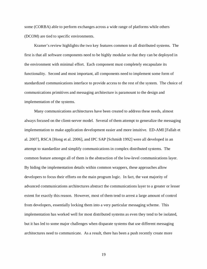
Figures 2-1 and 2-2 show the underlying architecture for message processing and data
transfer. The use of Message Port and Arbiter objects serves as the middle level in the MSRS
messaging architecture. The Message Port is responsible for receiving messages and sending
them via the communications layer. The arbiters distribute messages received on a port to the
various handlers that have been attached. This bears some similarity to the pre-processing and
interpretation layer of the Reflective Communications Framework in that they both send and

25
receives message and distribute them amongst processing methods. However, the Message Ports
and Arbiters used in MSRS are very tightly defined and do not enable a developer to customize
their behavior beyond how the messages are distributed amongst handlers. This inherently limits
the flexibility of MSRS in developing systems that use very specific messaging architectures.
Figure 2-1. Message arbitration layer in MSRS. Image taken from [Jackson 2007].
Figure 2-2. Communications layer in MSRS. Image taken from [Jackson 2007].

26
Figure 2-2 shows the low-level communications layer that is responsible for actually
moving the data between services and nodes. MSRS uses three modes of transportation: shared
memory for services on the same node, proprietary binary encoding for TCP-based
communications between nodes, and finally SOAP encoding for HTTP-based communications.
The mode and encoding scheme is determined by the relative locations of the services in
question. The end user has absolutely no control over the final representation of data being
transported over the pipe. This means that even with custom modifications to the serialization
scheme, developers using MSRS currently have no way to target other messaging formats,
effectively isolating the system. Needless to say, this is less than desirable in distributed system
deployment.
Windows Communication Foundation
The other approach developed by Microsoft to aid in distributed application deployment is
called the Windows Communication Foundation and has been directly built into .NET 3.0 and
later to aid in its distribution and use. To quote Andrew Troelson on the advantages of WCF:
“WCF provides a single, unified, and extendable programming object model that can be used to interact with a number of previously diverse distributed technologies.” [Troelson 2007]
In other words, it encapsulates a wide variety of APIs and processing capabilities that
enable a developer to rapidly create an application with minimal concern over implementation
details of the communications layer. By standardizing and abstracting the communications level,
WCF allows a programmer to focus on the logic behind a program rather than the often complex
messaging system. However, WCF is specifically designed for service-oriented architectures
that use one of several standard communications pipes; these are HTTP, TCP, and MSMQ. This
means that a developer can only easily create a WCF application that talks to other WCF

27
applications or Microsoft developed systems that support the particular service-contract model
implemented.
As with MSRS, WCF automatically handles serialization of messages as well as all of the
low-level communications and message distribution. While this is extremely convenient for
rapid application deployment, it is again very limiting in flexibility. Developers cannot easily
implement custom messaging architectures, rather having to develop the low-level
implementations themselves. The level of abstraction for the WCF messaging architecture is too
high for many developers to be able to use it for particular classes of distributed systems. The
primary reason for this lack of control is that the WCF messaging system is built directly on the
serialization toolset in .NET, inheriting all of its limitations.
Joint Architecture for Unmanned Systems
While the main networked systems community standardized their communications formats
early on, it is only relatively recently that the robotics community has attempted to develop a
common communications architecture. Sponsored by the Office of the Secretary Defense, the
JAUS Working Group defined a set of rules and guidelines that govern the creation of
compatible applications. The key features defined include communications protocols, an
extensible message set, and the exact format and structure of the serialized messages. By
implementing this architecture, a JAUS “component” can communicate with any other
component without additional configuration. Needless to say, this has been a boon to developers
as it guarantees compatibility between individual systems of vastly different behaviors and
implementations.
A JAUS system is service-oriented with components subscribing or supplying information
to others, either locally or remotely. A good way to view a JAUS network is as a virtualized
UDP network with the components communicating via nodes. The actual transport layer has
28
been abstracted, presenting the same interface for sending and receiving data. This allows
communications to occur across a wide range of protocols including UDP, TCP, serial,
Bluetooth, radio, and anything else that supports byte-formatted data transfer. In fact, the
general structuring of a JAUS message is virtually identical to that of a UDP message with both
a header and a contents section. The header describes source and destination addresses in the
JAUS network as well as size and type information about the contents. The contents themselves
are the serialized representation of the messages as defined by the Reference Architecture (RA).
The serialized form of the messages is designed to minimize the amount of data being
transported. Since JAUS applications have prior knowledge of the message sets, a very compact
representation can be used.
The virtualization of the JAUS network on top of the transport layer provides great
flexibility. However, deployment of a JAUS system is still a very complicated process. The
JAUS RA only specifies the final formats and protocols for data exchange but not the
implementation, which is left up to the developer. Unfortunately, this requires the creation of a
huge code base to handle the hundreds of messages as well as supporting methods. Properly
formatting messages for transport requires byte-level control of the serialization process. As has
been discussed earlier, since no toolsets enabling this are readily available in current
programming languages, developers are left to implement custom approaches that can take
inordinate amounts of time. Sometimes it takes years to finish a complete JAUS code base,
which is then very difficult to update due to the methods used.
The complexities involved in following the JAUS RA makes it an ideal candidate to
deploy as a reference implementation of the Reflective Communications Framework. The

29
details of its development are discussed in Chapter 3. It illustrates the proper approach to
development using the RCF and highlights the key features.

30
CHAPTER 3 APPROACH
This section discusses the implementation details of the Reflective Communications
Framework developed for this project. While the framework was implemented in .NET, it can
easily be deployed in any other environment that supports reflective programming.
Overview
As previously discussed, the framework consists of three tiers that isolate the functionality
of the various levels of communication. Figure 3.1 shows the relationship between components
of the RCF and those of the end user applications. This will be discussed in more detail later.
The lowest layer is the generalized communications interface that encapsulates all low-level
communications. These could include UDP, TCP/IP, serial, or any number of other interfaces
that are used to actually move the data from one application module to another. The second
layer, dubbed the message handler, performs pre-processing and interpretation of data being
routed through the communications interface. It also fulfills an arbitration roll that determines
where data should be routed in the application. The final level is the message definitions and
processing. This is used for conversions from application specific data to a low-level serialized
representation and back.
In large part, the system uses an event driven model giving developers maximum
flexibility in application design. They can combine or separate processing functionality as
appropriate, creating highly maintainable code with a native communications architecture. It is
also possible to dynamically change application behavior, providing extraordinary flexibility in
design. In addition, it is possible to completely separate the processing and management
framework from the application layer, enabling a developer to create a communications module
that can be easily dropped into any application with virtually no configuration required.

31
For demonstration, several abstract modules were created to form the foundation of the
framework. They provide all of the core functionality needed to enable communications routing
and processing. Developers using these base classes need only implement certain architecture
specific features to reach full functionality. The JAUS .NET reference implementation discussed
in the future work section will illustrate the ease and speed with which a communications
framework can be deployed.
Primary Architecture
Figure 3-1. Relationship between RCF components and end user components.
As can be seen in Figure 3-1, The RCF encapsulates three core components, the transport
layer, the base message handler, and the serialization library. The transport layer is abstracted to
provide a common communications interface between the operating system level I/O and the
message handler. The serialization library provides the functionality needed for automated

32
message conversions to and from a specified transport format, such as an array of bytes
commonly used in networking for UDP or TCP.
The message handler acts as the bridge between the RCF core functionality and that of the
application. It is responsible for interpretation and conversion of data and messages as well as
routing these messages to the appropriate parts of the application. The base message handler was
designed with all of the pieces needed to track the message definitions and processing methods
while also making it easy to route the data. It even incorporates a fully multi-threaded model to
separate the I/O interactions from the routing logic while avoiding potential lockups at runtime.
As such, it is the responsibility of the end user who is implementing a communications
architecture to add the logic needed for proper interpretation and routing of data. This is easily
accomplished through inheritance as the entire RCF is built in an object oriented language. This
is explained in greater detail in a later section.
The message definitions live in the user layer of the framework, but are directly accessed
by both the message handler as well as the serialization library. Thanks to reflection in .NET,
the ability of an application to determine information about itself, the serialization library is able
to dynamically process the messages based on information that the developers build into them.
At the same time, both the message handler and the application layer are able to access the same
definitions for their own use. The primary advantage of this approach is that the message library
can be written in a very compact and portable form without the need for large amounts of
customized code for simple I/O.
Data Flow and Logic
While the previous section gives a high level overview of the RCF and its use, it becomes
necessary to provide a more detailed explanation of the data flow through the system during
operation. Both sending and receiving of data follow similar patterns involving interaction

33
between the message handler, the serialization library, and the transport layer. Figures 3-2 and
3-3 illustrate the primary data flow in an RCF based system.
Figure 3-2. Inbound data.
Figure 3-3. Outbound data.

34
When processing an inbound message, several steps occur. First, the raw data is received
by the low level operating system protocols and then retrieved by whatever transport layer has
been selected. Next, the raw data is handed to the derived message handler for interpretation and
conversion. During conversion, information is pulled from the base message handler class to
determine how to properly invoke the serialization library. When the serialization process is run,
it retrieves specific information about the message types it is handling from the developer created
message definitions. The raw data is then converted into usable message objects that are
returned to the message handler. At that point, the message handler determines where to route
the newly received message in the application.
Sending an outbound message is essentially a reversal of the receiving logic. First, the
application passes a message to the message handler which then retrieves conversion information
from the base class. The serialization library is invoked, reading the message definitions from
the developer libraries. The converted message is then passed to either the message handler for
further processing or directly to the transport layer for final routing and delivery.
The main developer challenge is implementing the interpretation logic as it governs the
conversion of data to and from transport format. The operation of the serialization library,
transport layer, and base message handler are all predefined, but it is necessary to define when
and how the serialization process should be invoked. The design and implementation of a
derived message handler will be discussed in detail in later sections.
Reflection and Dynamic Reconfiguration
At the core of the framework is the reflection oriented model used to describe and
indentify all of the dynamic components. These include the message set definitions, processing
functions, and the structuring of the messages themselves. All of this information is extracted at
runtime to determine the program behavior.

35
The Microsoft .NET environment used to develop the framework defines several
constructs that enable reflective programming. Assemblies are the core of all .NET applications
as they contain all information regarding a compiled code library. These include executables and
libraries which encapsulate all functionality for a program. These assemblies can contain object
definitions, methods, references to other assemblies, and most importantly specific information
about each of these in the form of ‘attributes’. These descriptors can describe a wide range of
factors such as publicly visible names and interpretation methodology. Figure 3-4 shows the
abstract layout of a .NET assembly.
Assembly
object
object
method
methodmethod
attributeattribute
attributeattribute
Figure 3-4. Structure of a .NET assembly.
Using a combination of built-in and custom created attributes, assemblies can be created
that are fully self-descriptive to applications that know how to interpret them. This ability is
leveraged by the Reflective Communications Framework to dynamically gather information

36
needed for program execution. Developers can create message and processing libraries that
contain all information needed for full operation with minimal addition to the code base by
added short tags to the code that do not interfere with the structuring or readability. This allows
the developer to create an application with virtually no restrictions and to even adapt existing
applications to the new framework with minimal effort.
Three classes of custom attributes were specified to aid framework development. The first
group identifies methods that are used to process messages that have arrived. The second group
acts as an identifier for the individual messages in a message set. This is used to dynamically
determine which objects need to be allocated at runtime during interpretation of data. The final
attribute group describes the actual message structuring. This is used by the generalized
serialization scheme to control which components of a message are serialized, how they are
interpreted, and the exact processing order. The implementation of the serializer determines the
final representation of messages being transported.
Attribute usage in .NET: A .NET attribute is an object definition that stores information
about the piece of code to which it has been attached. They can store virtually any type of
information that can be processed at compile time, making them very useful for storing generally
accessible data about application modules. This data is stored in internal fields and can be
accessed by a number of means, the most common of which is ‘properties’. Properties are a
.NET construct for code readability that encapsulates method access to fields while providing an
interface that still looks like direct field access.
Attributes are very easy to utilize in .NET assemblies. They are added to code in a manner
similar to comments. The code layout remains unchanged save for an extra line that is processed
by the compiler when generating the assembly. The proper form of attribute usage is as follows:

37
BNF: <attribute> ::= “[“ <name> “(“ <argList> “) ]” <targetCode> <argList> ::= λ | <value> | <value> “,” <argList>
| <arglist> “,” <propList> <propList> ::= <property> | <property> “,” <propList> <property> ::= <name> “=” <value> C#: [<name>(<argList>)] <targetCode>
One will notice that the argument list provided to an attribute constructor can contain
multiple property assignments of the form <name> = <value>. This is a .NET specific
feature that allows a developer to assign additional values to an object at creation time without
having to write extra lines of code. For example, the RCF defines an attributes for specifying
fields to process name PackableMember. This attribute stores several pieces of data regarding
the order and nature of processing. A pseudo-C# form of its usage might be:
[PackableMember(0, true, Optional=true, DependencyIndex=5)] int number;
The above example shows all of the elements of the BNF description. Two values are
passed in as part of the argument list, followed by a property list containing two elements. This
associates four pieces of data with the immediately following number field. Note that the single
line of attribute code does not affect the functionality of the object itself, instead attaching data to
it that can be processed separately. As such, an application can be rapidly converted to
compatibility with the Reflective Communications Framework. More detailed examples of
attribute usage are presented in the section on message structuring.
Communications Interface
At the core, all communications between computer systems occur on a low-level interface
that is used purely to move data from point to point. While the actual implementation is heavily
dependent on the particular interface, all of them share one common trait: they are used to send

38
and receive data that represents information meaningful to the application. Therefore, it is
possible to encapsulate virtually any communications interface in a more general form that
simply provides access to the base functionality needed.
This has the distinct advantage of hiding the low-level, implementation specific details
from the developer who is only interested in the data travelling over the pipe, not how it is
actually transported. This also enables higher levels of abstraction because other application
pieces can easily send or be notified of the arrival of new data. The communications interface
exposes two features to the outside, a method to send data and a tie-in to pass newly received
data. Figure 3-5 shows the abstraction of the communications interfaces. All interfaces have the
same access points publicly visible. Specific transport types will also require hidden custom
implementation to process the data routed through the exposed access points.
Communications Interface
Hidden Implementation Publicly Visible
Send
Data Received
Transport Specific Implementation
Initialization
Figure 3-5. Communications interface structuring.
The actual implementation of the Send function has not been specified as it depends
heavily on the transport layer requirements. However, all program elements that utilize a
communications interface will see a method that accepts an object to be converted and sent over
the pipe. The Data Received access point is used to notify an application when new data has
arrived on the low-level layer. This is accomplished by attaching one or more methods to the

39
notifier that are invoked when new data is available. The details of when the methods are
invoked are transport layer specific. An example implementation using simple UDP sockets is
presented in the next section.
UDP communications interface: The UDP communications interface is very simple in
structure, utilizing many existing objects in .NET. The three main components are a UDP
socket, an IP address that represents the destination for the send operations, and a receive thread
that is responsible for pulling information from the socket. The send and data received
functionality are publicly visible while the receive thread that actually grabs the data is
completely hidden and managed by the class. Figure 3-6 shows the data type encapsulation of
the UDP interface as well as the general structure of the send functionality. Notice that Send is
very simple in form because the serialization process is automated and only needs to be invoked.
Figure 3-7 shows the layout of the receive thread that is responsible for asynchronous storage of
data that will be processed by another part of the framework.
UDP Communications Interface
Socket
Destination IP
Receive Thread
Send
serialize the object data to byte array
representation
send via the socket to the destination
Figure 3-6. Data types and send functionality for UDP com interface.

40
Receive Thread
Start
End
allocate buffer
listen on socket
read data from socket into buffer
run thread?
invoke Data Received methods
yes
no
Figure 3-7. Receive thread flowchart.
When the send method is invoked, it is responsible for serializing the message object and
sending the information to the predefined destination via the internal socket. The actual
serialization is performed by a specific implementation of the generalized serialization object
that is targeted at generating packed byte array representations of the messages. This will be
discussed in detail in a later section. The receive thread is also a relatively simple construct. The
thread monitors the socket for new data then invokes the Data Received methods, passing the
newly arrived array of bytes as the sole parameter. These methods have no knowledge of the
inner workings of the UDP communications object and could just as easily be used to process
data from any other wrapper.

41
Message Handler
While the communications interface is responsible for getting data to and from application
modules, the message handler is performs several critical functions related to processing of that
data. First and foremost, it acts as the primary interface to the communications interface in an
application. It performs the appropriate final operations needed for proper interpretation of raw
data coming off the pipe. Derived handlers can also control aspects of sending of data on these
interfaces if deemed appropriate. Second, it has knowledge of the currently supported messages
that it uses in the interpretation of the data. This knowledge store can be dynamically changed.
Third, the handler acts as the final message router for the application. Portions of the application
can be dynamically linked to the message handler along with information about the types of data
that they wish to process. This approach allows the developer to dynamically change the
message set and processing capabilities of the application with relatively little effort. The usage
is the same regardless of structuring.
Figure 3-8 shows the data structure for the base message handler while Figure 3-9
illustrates the relationship between the message handler and both the message libraries and
processing methods. Message types and processors are tracked in much the same way. Lists of
objects are maintained that can be used to rebuild the hashtables at any time. Hashtable elements
are lists that contain the actual information of either message types or methods to invoke. This
approach provides the flexibility for the message handler to dynamically update its knowledge
base and perform error checking, adding an element of safety to the configuration. Note that
processing methods can be added and tracked either as part of an object or individually via
encapsulation.

42
Message Handler
Message Processing Info
Object
List of Methods
Method
List of Message Processors
Hashtable of Processing Methods
List of Methods
Message Type Info
Assembly
List of Data Types
Data Type
List of Assemblies
Hashtable of Data Types
List of Data Types
Figure 3-8. Data structure for the message handler.
Figure 3-9. Handler access of message library and processing methods.
In addition to the tracking capabilities, the base message handler definition is built as a
multi-threaded module to allow asynchronous, non-blocking processing of messages and data.
Data will typically be received by a method that is attached to the communications interface
being used by the handler while processing is performed in a specific method run by the stand-
alone thread. Since the threading setup is already provided, it is only necessary for a developer

43
to override the threaded method to gain its benefits. The chapter describing the JAUS .NET
reference implementation will show in greater detail how these pieces interact.
Dynamic Message Set
Much of the information regarding known message types and processors is gathered using
the reflective capabilities of the .NET environment. A message handler is always created with
knowledge of the specific tag used to identify message types for the communications framework
being used. When an assembly is attached to a message handler, the handler filters the assembly
information for all data types that have been marked with the matching attribute. This is used to
build a hashtable of known message types. For example, the JAUS .NET framework uses a
JausContents attribute to mark data types as usable for messaging. This is used in conjunction
with another attribute that identifies the message as being processable by the serialization library.
The code would look similar to this:
General: [Packable] [<IDtag>(<GUID>)] <messageDefinition> JAUS: [Packable] [JausContents(<GUID>)] <messageDefinition>
The table of known types is organized by globally unique identifiers (GUIDs) that are
specific to each message type that serves two purposes. First, data types can be quickly pulled
using the known GUID. Since a GUID is a unique identifier, this can be used to rapidly filter the
known data types based on information passed during messaging. Secondly, error checking can
be performed to look for duplicate or conflicting type definitions. If one or more assemblies
assigns the same GUID to multiple data types, the ability to differentiate and process the

44
messages properly will be lost. Figure 3-10 shows the process for populating the table of known
data types.
At any time during operation, an assembly can be attached or unlinked from a message
handler, triggering a refactoring of the data type hashtable with full error checking. The entire
process is automated in the base class only requiring knowledge of the attribute type to extract
from the assembly. An important note is that the hashtable is meant to be used in conjunction
with the interpretation aspect of the message handler, providing it with information about the
types of data that can be processed. It is left up to the developer how this is used, but a
suggested structure is presented in the next section.
Get assembly from list
Retrieve message identifier attributes foreach identifier Get matching list in
hashtable
Check for lists with multiple entries(i.e. duplicates definitions)
Add identifier to list
Figure 3-10. Data type hashtable update.
The creation of the hashtable is a two-step process involving collecting and sorting of the
attributes and then checking for duplicate definitions. Attribute information is sorted into lists of
common GUIDs. As previously discussed, each GUID should be unique, so lists containing
more than one entry indicate a conflict in definitions. An exception is thrown to signal the
problem, though this does not have to break the program execution. It is possible for the
developer to account for situations that break the design intent with proper exception handling.
This will often be performed in the interpretation portion of the message handler.
Interpreter
The interpretation aspect of the message handler is the part that allows the developer to
customize the behavior of the derived class to properly implement a messaging architecture.
45
While the abstract message handler class provides all of the functionality needed for automated
management of the message type and processor knowledge base, the interpreter is far too
complex to effectively generalize without overly restricting developers. Rather, the interpreter is
a targeted implementation that ties the abstract management aspects to the specific configuration
needed for a custom messaging architecture. Typically, a developer will want to create an
interpreter with several core pieces.
First is a method used to receive data updates from the communications interface. This
method can be used to asynchronously accumulate serialized message data for later processing.
Properly implemented, this allows the application to accept relatively high message traffic
without loss of information, though this is also dependent on how the communications interface
is written. This method can also be used to monitor connection health.
Second is a processing thread that is used to deserialize the raw messages as they are made
available by the update method just mentioned. To aid in development, the base message
handler class has been pre-built as a multi-threaded object. Any message handler that derives
from this class only needs to provide implementation for the ThreadFunction method to gain
access to the multi-threaded capabilities. The deserialization scheme used is core to the
messaging architecture as it determines how to interpret the raw data. The generalized serializer
will be used here to process portions of the data, but the final creation of message objects still
needs to be controlled by this thread. For example, a message might contain a header and a
body, with the header describing the nature of the body, such as the data type identified by a
GUID. The thread would create and interpret the header to determine the type of body to
deserialize. The data type can be retrieved from the hashtable of known types and if present,
used to deserialize the body.
46
Third is a section that is responsible for passing reconstructed messages to the various
application pieces. As previously mentioned, a second hashtable of known message processing
methods is maintained by the message handler. This enables the interpreter to easily determine
where a particular message needs to be routed. The next section discusses how this information
is made available.
While this is the recommended approach to implementing the interpretation aspect of a
message handler using the Reflective Communications Framework, it is by no means the only
way. Some architectures might only use a very limited message set or might place great
restrictions on the interfaces to which particular message types are routed. They would not need
such a complex setup for smooth functioning, and in fact might even be able to completely
ignore the data type hashtable, potentially improving performance. Then again, there may be far
more complex architectures which require a more involved implementation. It is left up to the
developer to determine the optimal approach for the particular communications framework being
created.
Message Routing
The final service that the abstract message handler provides is maintenance of a table of
methods that are meant to be used as message processors. As with the table of message types,
this information is updated dynamically, allowing addition and removal of message processors
on the fly. This is accomplished by two means, both involving the use of reflection. The first
automatically gathers the information from an object that may contain processing methods. The
second allows more explicit addition of methods.
For the automated approach, an object is added to the list of message processors.
Attributes are then extracted in much the same way as with message types, allowing the handler
to update the table. The attribute used to identify processing methods is aptly named

47
MessageProcessor. It contains the GUID of the message type that the method can process,
which is meant to be used in conjunction with the message types table. Multiple
MessageProcessor attribute tags can be applied to a single method if desired to allow a single
method to process a variety of data types. Once a method has been identified as a message
processor, it is added to the appropriate list(s) in the hashtable for later retrieval during message
routing. Proper syntax for specifying a processor is:
[MessageProcessor(<GUID>)] void <methodName>(<argList>) { ... } <argList> ::= λ | <type> <argName>
| <type> <argName> “,” <argList>
The argument list is determined by the architecture and the exact form of a processing
method needs to be explicitly defined for the message handler. This allows the handler to ensure
that a method marked with a MessageProcessor attribute is structured properly, thereby avoiding
invocation errors. The form is expressed using a delegate, a .NET construct that acts as a handle
to a method. For a message handlers, the proper structure for a delegate is:
delegate void <delegateName>(<argList>); <argList> ::= λ | <type> <argName>
| <type> <argName> “,” <argList>
A message handler initialized with a delegate type will only process methods that exactly match
the format given and have been marked as message processors. Any other methods are ignored.
The second approach for added message processors allows a developer to explicitly specify
a method to act as a processor and the associated GUID of the message type that it should be
passed. While the automated approach will be the most widely used, this alternate method can
be useful in situations where the exact data type that needs to be handled may not be known until
runtime. Certain service oriented architectures may make use of this feature as they tend to be
highly dynamic in nature with a continuously changing structure. Dynamically added methods

48
still have to follow the same structure as the delegate used by the message handler. Adding them
follows the form:
<handlerName>.AddMessageProcessor( new <delegateName>(<instance>.<methodName>), <GUID>);
Notice that the message GUID will be associated with the instance method, guaranteeing that
only messages matching that ID will be routed to the method. If one method in an object is
supposed to process several messages with different GUID’s it will have to be added multiple
times as only one ID can be associated at a time.
Message routing is accomplished by retrieving the list of processing methods from the
table associated with the GUID of the message that has been received. These methods can then
be invoked as deemed appropriate by the interpreter without prior knowledge of exactly which
parts of the application have requested the information. Properly implemented, this allows
flexible asynchronous processing of the data.
Generalized Serialization and Message Structuring
While the message processor will act as the important middle layer between low-level
transport and the main application, the capacity to implement a messaging architecture would be
very limited without the ability to convert messages to and from transportable formats. This is
where the generalized serialization design becomes important as it needs to provide a very
flexible, yet easily utilized interface for defining message structuring and interpretation. This
can be accomplished via a combination of attributes that identify the parts of the messages that
need to be handled along with a set of functions that recursively processes these pieces, a
necessary feature to allow nesting of data types. It is very likely that at least some messages in
any architecture will require the use of custom types that need to be handled in a very particular
manner. While the conversion of standard data types such as integers can be pre-specified in the
49
serializer, any non-standard types need to be explicitly described. The following sections discuss
the components necessary to provide the flexibility and robustness to implement a wide range of
message structures. These include the class that performs the serialization steps and the
attributes used to define message structure.
Recursive Serialization/Deserialization
The core of the RCF lies in the serialization class that is responsible for all data type
conversions. Dubbed a Packer, this object must be able to dynamically gather the information
from the data types being processed, sort and organize this information, then work sequentially
through the collected instructions to perform the conversions. In addition, it needs to be able to
recognize and handle both standard and non-standard data types as well as performing recursive
operations to handle any nested objects.
Fortunately, the process can be split into two distinct layers, one providing the overall
framework for data extraction and iterative behavior while the other provides implementations
specific to the particular data representation being targeted. This translates to an abstract base
class that defines the common processes required for all serialization and deserialization along
with a set of derived classes that contain functionality for specific conversions and data storage.
For example, a BytePacker class was derived from the base Packer class to handle conversions
of messages to and from byte arrays using many of the standard tools built into the .NET
environment. While this might address the needs of many developers, they can create their own
custom packing objects to target other formats or representations if desired.
A distinct advantage of separating the functionality into two layers is that a message object
will be processed in the same way during general conversions, maintaining its overall structure
regardless of the targeted communications format. This processing will not change under any
derived framework. The exact representation of the data can be precisely controlled by the

50
derived packing object giving the developer virtually unlimited flexibility in transport
implementation. In fact, using multiple derived objects, an application could use the same
design and message set and still be able to communicate with a number of other architectures.
The derived packing classes, combined with properly structured message handlers, would be able
to target these architectures dynamically, greatly improving interoperability.
Packer design
The base Packer class implements the overall architecture for serialization and
deserialization processes. This includes retrieval of packing information, invocation of
specialized processes, and invocation of conversion and storage processes. The information
required for proper operation is supplied in large part through the use of attributes placed in the
message definitions, essentially providing an instruction set for the Packer to follow. These
attributes are discussed in detail in a later section. The system has been designed to keep a
logical separation of the format specific conversion processes and the more generalized flow
common to all packing operations. Figure 3-11 lays out the logic flow for the serialization and
deserialization methods. The structure is virtually identical with the primary difference being
how results from the associated processing methods are handled. Figures 3-12 and 3-13 show in
greater detail the layout of serialization, deserialization, and special processing methods.
The base Packer class defines five methods to handle processing of data. These functions
handle several key services:
• Serialization of data. This is the conversion function that handles all supported data types and provides recursion.
• Storage of the serialized data. Once converted, the data needs to be stored until the rest of the data has been processed, at which point all of the data will be collected and returned.

51
• Final collection and organization of the serialized data. After all of the component parts of a message have been processed, it is necessary to take the various pieces and combine them into a single representation of the object.
• Deserialization based on data type. This is where deserialization occurs for all data types that can be dynamically allocated via reflection.
• Deserialization of pre-allocated objects.
It is necessary for the developer to override these methods to provide implementation specific to
the targeted format. For example, the supplied BytePacker defines methods specific to handling
and conversion of data in byte array form. By the same token, one could easily create a derived
packer definition that instead targets strings of characters or even an XML-based serializer. The
data handled by the conversion routines would be the same regardless of target format thanks to
the abstraction of the base Packer class and the attribute-based message structure.
Figure 3-11. Serialization/Deserialization flowchart.

52
Specialized MethodsSerialization of Member
Invoke Method
ConvertReturn Value
Store Result
Retrieve Value
Convert Value
Store Result
Figure 3-12. Serialization process for member fields and special processing methods.
Specialized MethodsDeserialization of Member
Invoke MethodRetrieve Raw Data
Convert Value
Store Resultin Member
Figure 3-13. Deserialization process for member fields and processing methods.
The first step in any packing process is the retrieval of relevant packing information by
reflection. This provides a collection of member fields to be converted as well as several
collections of specialized processing methods that have been defined in a message definition.
These collections are sorted by index as discussed in a previous section to ensure correct order of
handling. All of this information is encapsulated in a construct known as PackingInfo to allow
ease of transport and data access. Both packing and unpacking operations, which perform
serialization and deserialization respectively, follow the same flow. After obtaining the packing
information, they invoke the pre-processing methods followed by an iterative handling of

53
member fields and mid-processing methods. Finally, the post-processing methods are invoked
and the operation is completed. In the case of packing, the serialized representation is compiled
and returned, while unpacking returns an object containing the deserialized data.
The handling of fields versus specialized methods during serialization is very similar. In
both cases data is retrieved, whether directly from the field or as the return from a method, then it
is sent to a conversion method in the derived class. The return value is the serialized
representation of the data that is then added to the overall store for the object. The conversion
function is responsible for handling both standard and non-standard data types. If a non-standard
type (i.e. a nested, Packable object) is encountered, an identical packing process is invoked, in
effect a recursive operation. This will occur to any depth as each packing process only considers
the current data type.
Deserialization of fields is somewhat different from the way in which the unpacking
methods are handled. While serialization could use virtually identical processes for data
handling in both situations, deserialization requires a more specialized approach. When
processing a field, the raw data is handed to the unpacking function in the derived class along
with the data type or object to target. The appropriate section of raw data is converted and the
result returned to be assigned to the field. In the case of standard data types, data conversions are
relatively straightforward. Non-standard types require another unpacking process to be invoked,
behaving in a recursive manner much like the serialization process. Again, this recursion will
occur to any depth as long as the raw data can be interpreted properly. It is also important to
note that unlike the packing conversion method that always received an object to handle, the
unpacking method can be given either a data type or an object to target. The reason for this was
mentioned in a previous section when discussing the need for pre-allocated objects in some

54
situations. Here, the object which should store the deserialized data is retrieved from the
member field and passed to the unpacking method. The method then assigns data to the
appropriate components as deserialization occurs. Finally, the fully unpacked object is
reassigned to the member field which provided it originally.
Specialized methods that have been invoked during deserialization do not return data, but
rather are given the raw serialized data and a reference to the packing object itself. This allows
them to invoke unpacking operations themselves if needed without breaking the generalized
model for message structuring. The reason for this is that the methods only see the packing
object, but not the specific data representation nor any of the underlying processing. While this
feature will be rarely used, there may exist situations where a generalized message structure
would be impossible to implement without it.
So far only the base implementation of the packing object has been discussed. However,
for a packer to be useful, it needs more than the core iterative processing methods. These
methods call upon functions in the derived classes that handle specific conversions to and from
the representative data type and format. One of the most common formats used in distributed
systems is byte array representations of the data as this is extremely easy to implement and
network communications utilize the same format for their packets. The next section presents a
derived packing object that specifically targets conversions to and from arrays of bytes. This is
both a useful tool that will likely be used in many messaging architectures as well as a
demonstration of how to implement a custom serialization object.
Targeted implementation example: BytePacker
When deriving a customized serialization processor, the developer must consider a couple
of key points. The first is what standard data types and formats will be supported by the
architecture and which ones require pre-allocation. As previously discussed, certain data types

55
may be best handled as pre-allocated objects to maintain a generalized message structure and
implementation. While the exact types that require pre-allocation is up to the developer, the
example implementation presented in this section will highlight which types are best suited for
particular approaches. Typically a derived packer object will support all of the standard types
such as integers and doubles as non-allocated types while more complex representation like
multi-dimensional arrays will require pre-allocation.
The second consideration is how to handle errors in data processing. There exist situations
where raw data coming in has been corrupted, cut short, or somehow damaged in such a way as
to make proper deserialization impossible. Also, a message may be created that contains a non-
supported data type in one of its member fields; for example, an object not marked with
Packable. However, a developer should also consider the performance ramifications of error
handling. For example, many languages support exceptions, which allow a piece of the
application to signal that an error has occurred and provide specific information about it. While
extremely useful, this feature is also computationally expensive and has the unfortunate
drawback of interrupting the application at that point. It is up to the developer then to decide
whether the potential performance hit is acceptable for the added safety or if more direct
approaches to error handling are more appropriate for the targeted implementation.
Development of the BytePacker class targeted all of the standard data types and took a
simpler approach to error handling. Like all objects derived from the ‘Packer’ class, it was
necessary to override the five methods to handle processing of data:
• Serialization of data. This handled conversion of data into byte array representations, essentially the in-memory storage of the data.
• Storage of the serialized data. The converted data is dynamically added to an internal array of bytes in order of processing. The order is determined by the numbering of the PackableMember attributes in any particular data object.

56
• Final collection and organization of the serialized data. The valid data from the internal array is copied to an array of appropriate size and returned. This is a very fast operation using an optimized approach that is discussed in the next chapter.
• Deserialization based on data type. This method handles the standard data types that can be dynamically allocated by the reflective runtime.
• Deserialization of pre-allocated objects. This handles the data types that require special pre-processing by the developer due to specific format restrictions.
In the BytePacker implementation, storage and compilation of the serialized data is the
simplest of steps. The class contains an internal list of bytes used to store serialized data as it
becomes available. As the arrays of bytes are received from the serialization method, they are
appended to the list; when serialization is complete, the list is converted to a single array of
bytes. These steps are automatically handled by the functionality built into .NET and should be
available in any language that supports generics or templates.
The serialization method is relatively simple, yet lengthy due to the number of explicit
types that it compares against. These include the standard booleans, characters, bytes, several
types of integers, and several types of floating point numbers, all of which can be processed by
environmental tools. Arrays, lists, and other collections share a common trait in that they
provide the ability to iterate over their elements, known as IEnumerable. This has allowed
development of a general loop that processed the individual elements. For efficiency and
control, the data type is first checked for the ‘Packable’ attribute. If matched, the data is
processed by a Packer object, otherwise it is sent to the other routines for analysis. This process
is repeated indefinitely until all the data has been processed. Figure 3-14 shows the general
process for serialization. Three main regions handle simple types, iterative types like arrays, and
finally unrecognized types. These unrecognized types may be nested data types as discussed
previously.

57
The deserialization routines are very similar in layout to the packing method. The main
difference is that the method that operates based on data types alone handles the simple types and
dynamically allocated Packable types whereas the method that handles pre-allocated objects
deals with the more complex types like arrays, lists, and strings as well as Packable objects.
This is akin to splitting the flow of the packing routine after the processing of simple types and
creating two methods. The layout of these methods is shown in Figure 3-15.
Pack Data
Check for Simple Types(byte, char, int, float, etc.)
Check for Iterator
foreach Element
Pack Data
return byte
Convert Data
conversions
Packer.Pack()
Not Simple Type
IteratorNot
Is ‘Packable’?
Return Result
Return null
Return Total Packed Data
Return Converted Value
Simple Type
Figure 3-14. Serialization of data in BytePacker class.

58
Unpack by Type
Check for Simple Types(byte, char, int, float, etc.)
return byte
Convert Data
conversions
Packer.Pack()
Unpack Pre-Allocated
Packer.Pack()
Check for Complex Types(arrays, lists, etc.)
Process Array
other
conversions
Figure 3-15. Deserialization routines by simple data type and by pre-allocated type.
Due to limitations of the .NET environment, complex types other than arrays, lists, and
strings are difficult to handle in a general sense as just about any custom object could be
designated IEnumerable, meaning that it contains custom implementations for iterating over its
elements, but not assigning values to them. However, this is not an issue as a developer would
designate this object as Packable and could take control of the serialization process, bypassing
the issues of unknown data types.
Custom Data Types
When attempting to address the issue of custom data types in a generalized messaging
framework, it becomes necessary to identify the common traits amongst the myriad
representations available. Any data type used for messaging is likely to store the information in
internal fields. The order in which these fields are processed during serialization determines the
final message structuring. However, simply converting the individual fields in the correct order
will be insufficient to handle more complex messages. There may be messages with mutable

59
structures that depend on various factors at runtime, requiring intermediate processing to
determine which fields need to be handled.
Taking these factors into account, a set of common features can be compiled that together
should address the needs of a large number of messaging architectures:
• Specify which fields should be processed during serialization/deserialization. Note that the term ‘field’ is used to represent any construct that can be used to both set and retrieve a piece of data.
• Indicate optional fields and their dependencies. There may exist situations where a field should only be processed if one or more conditions are met. This will allow the developer to easily create a changing message format.
• Specify methods for custom handling of data at different stages of processing. Some messages may require highly specialized routines to appropriately handle conversion to and from the transportable format.
The attributes that have been developed to address these needs fall into two categories:
those attached to fields that represent the data and those that are attached to methods used for
specialized processing. Following is a complete pseudo-code example of a message definition to
illustrate the primary features and usage. The details of each part will be discussed in detail in
later sections.
BNF: <messageDef> ::= “[Packable]” <messageCode> <messageCode> ::= <modifiers> <name> “{“ <bodyCode> “}” <bodyCode> ::= ( λ | <memberAttribute> (<field> | <property>) | <methodAttribute> <methodCode> | (<field> | <property> | <methodCode>)
) <bodyCode> <memberAttribute> ::= “[PackableMember(“ <argList> “)]” <methodAttribute> ::= “[DependencySpecifier(“ <argList> “)]” | <specialName>
C#: [Packable] public Message { [PackableMember(0)] int _id;
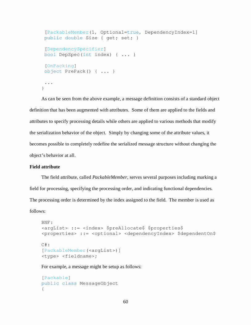
60
[PackableMember(1, Optional=true, DependencyIndex=1] public double Size { get; set; } [DependencySpecifier] bool DepSpec(int index) { ... } [OnPacking] object PrePack() { ... } ... }
As can be seen from the above example, a message definition consists of a standard object
definition that has been augmented with attributes. Some of them are applied to the fields and
attributes to specify processing details while others are applied to various methods that modify
the serialization behavior of the object. Simply by changing some of the attribute values, it
becomes possible to completely redefine the serialized message structure without changing the
object’s behavior at all.
Field attribute
The field attribute, called PackableMember, serves several purposes including marking a
field for processing, specifying the processing order, and indicating functional dependencies.
The processing order is determined by the index assigned to the field. The member is used as
follows:
BNF: <argList> ::= <index> $preAllocate$ $properties$ <properties> ::= <optional> <dependencyIndex> $dependentOn$ C#: [PackableMember(<argList>)] <type> <fieldname>;
For example, a message might be setup as follows:
[Packable] public class MessageObject {

61
[PackableMember(0)] int field1; [PackableMember(1)] int field2; }
When processed, field1 would be handled first followed by field2 because its index value
of 0 is less than that of field2. However, if the developer needed to reverse the order of handling,
then the only change would be to swap the index numbers of the fields. This effectively
separates data type design from the representation in the messaging architecture, requiring
minimal modifications by the developer to completely change the behavior. The only restriction
on use of the PackableMember attribute is that it cannot be applied multiple times to a single
field. As mentioned previously, the field attribute can also be used to indicate dependencies. It
can contain information about whether or not a field is ‘optional’ as well as specifying
dependency on a method that will determine if the field should be processed. The usage of said
method will be discussed in more detail later in the proposal.
One final feature of the PackableMember attribute is the ability to specify pre-allocated
fields. While this might seem like an unusual or restrictive flag, it is necessary for proper
processing of more complex data types. This results from the way in which the Packer class
leverages the reflective allocation of data types. It is possible to allocate an object of a type that
is only known at runtime, allowing a program to dynamically create objects as needed. The RCF
attempts to generalize the process, which inherently limits the allocation to being type-based
only. Unfortunately, specifying the data type alone is not always sufficient to properly allocate
the object. As a result, it becomes necessary for the targeted type to be processed as a pre-
allocated object that itself contains the information needed for proper processing.
Looking at arrays as an example again, one will realize that for an array to be deserialized
properly its size must be known ahead of time. A pre-allocated array can provide its size

62
information to the environment, allowing a generalized approach to be taken in deserialization.
However, if the array has to be dynamically allocated by the deserializer, the general nature of
the process would be broken as specific constructs would be required to pass the size information
through the various levels of processing. Strings and lists face similar problems in that they too
contain multiple elements with the added complexity of variable length. As a result, the
following three data types must be pre-allocated by the developer: arrays, lists, and strings. In
each case, the deserialization process uses the pre-allocated sizes of the specialized data types to
iterate over their elements and populate them. The JAUS .NET chapter illustrates the proper use
of pre-allocated elements with several sample messages that require the added complexity.
However, do note that beyond these three special cases, it is highly unlikely that a developer will
need to pre-allocate other elements.
Processing method attributes
The collection of attributes used to specify specialized processing methods contains a
number of members, none of which are particularly complex in design. They address the issues
of dependencies and intermediate processing that might become necessary in some message
implementations. These attributes have features similar to the field attribute that allows the
developer to specify processing order and identification information.
As previously mentioned, optional fields indicate a method that will determine whether or
not the field should be processed. This method is identified by a GUID and is passed the ID of
the field that should be analyzed. The GUID is attached to the method via and attribute named
DependencySpecifier that is used to identify and invoke the method at runtime. Since each
dependency method is assigned a unique ID, it is possible to have an unlimited number of such
processors if needed. The proper usage of the Dependency specifier is:
[DependencySpecifier(<methodIndex>)]
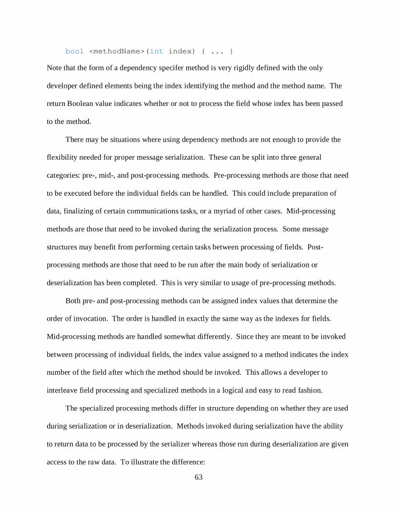
63
bool <methodName>(int index) { ... }
Note that the form of a dependency specifer method is very rigidly defined with the only
developer defined elements being the index identifying the method and the method name. The
return Boolean value indicates whether or not to process the field whose index has been passed
to the method.
There may be situations where using dependency methods are not enough to provide the
flexibility needed for proper message serialization. These can be split into three general
categories: pre-, mid-, and post-processing methods. Pre-processing methods are those that need
to be executed before the individual fields can be handled. This could include preparation of
data, finalizing of certain communications tasks, or a myriad of other cases. Mid-processing
methods are those that need to be invoked during the serialization process. Some message
structures may benefit from performing certain tasks between processing of fields. Post-
processing methods are those that need to be run after the main body of serialization or
deserialization has been completed. This is very similar to usage of pre-processing methods.
Both pre- and post-processing methods can be assigned index values that determine the
order of invocation. The order is handled in exactly the same way as the indexes for fields.
Mid-processing methods are handled somewhat differently. Since they are meant to be invoked
between processing of individual fields, the index value assigned to a method indicates the index
number of the field after which the method should be invoked. This allows a developer to
interleave field processing and specialized methods in a logical and easy to read fashion.
The specialized processing methods differ in structure depending on whether they are used
during serialization or in deserialization. Methods invoked during serialization have the ability
to return data to be processed by the serializer whereas those run during deserialization are given
access to the raw data. To illustrate the difference:

64
[<packingAttribute>($index$)] object <packMethodName>() { ... } [<unpackingAttribute>($index$)] void <unpackingMethodName>(Packer packer, object rawData) { ... }
Notice that “packing methods” are designed to return data for processing by the packer
whereas “unpacking methods” are given access to the packer and raw data for specialized
processing. The structure was designed to maximize the flexibility of message implementation
by providing developers more direct access to the underlying message conversion should they
need it. During serialization, this effectively allows them to dynamically add data that cannot be
effectively stored in message fields and in deserialization provides tools to directly work with the
compact representation of the message. While this might seem like a very complicated set of
tools, one must realize that the vast majority of message architectures can be implemented
without many of them. They are provided to improve the flexibility of the framework to handle
some of the more obscure or difficult designs that may be encountered.
Inheritance
One last feature built into the messaging definitions is the ability to carry structure through
the chain of inheritance. This allows a core object to be defined that contains all of the fields and
structure common to a wide range of messages. Each of these messages can then build on the
single base object, reducing code complexity and volume while centralizing the design for
common objects. Inheritance is automatically handled by the system, so no special
considerations are needed when defining derived messages. The only stipulation is that the
indexing of the new packable members and processing methods in the derived classes not
conflict with those of the base class. For example:
[Packable] class BaseMessage
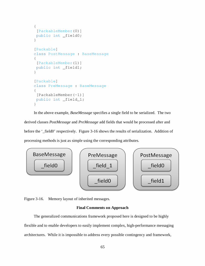
65
{ [PackableMember(0)] public int _field0; } [Packable] class PostMessage : BaseMessage { [PackableMember(1)] public int _field1; } [Packable] class PreMessage : BaseMessage { [PackableMember(-1)] public int _field_1; }
In the above example, BaseMessage specifies a single field to be serialized. The two
derived classes PostMessage and PreMessage add fields that would be processed after and
before the ‘_field0’ respectively. Figure 3-16 shows the results of serialization. Addition of
processing methods is just as simple using the corresponding attributes.
Figure 3-16. Memory layout of inherited messages.
Final Comments on Approach
The generalized communications framework proposed here is designed to be highly
flexible and to enable developers to easily implement complex, high-performance messaging
architectures. While it is impossible to address every possible contingency and framework,

66
analysis of the traits common to all communications systems identified the key aspects that
needed to be handled. This chapter presented a very high-level view of the reflective framework
and its underpinnings while discussing the key features that give it the flexibility required.

67
CHAPTER 4 JAUS .NET
The JAUS .NET reference implementation demonstrates how to deploy a communications
architecture using the Reflective Communications Framework. It builds off of all of the pieces
and finally integrates them into an easily used platform for component development. This
chapter will discuss the details of how the JAUS architecture maps to the RCF and show detailed
examples of how to extend and utilize the framework properly.
Overview of the JAUS Reference Architecture
The background chapter presented a brief overview of the JAUS RA. However, to be able
to effectively explain how JAUS was implemented using the RCF, it is necessary to inspect how
the architecture matches with parts of the RCF. As previously discussed, the JAUS RA is similar
to a virtualized TCP/UDP network, complete with a client-server model, that overlays the actual
communications layer. It uses a very rigid communications protocol that defines exact message
structure as well as the protocol for creation and maintenance of service connections. A piece of
central routing software called a node manager is a requirement for operation of the framework,
but the form and structure are not defined. To simplify deployment in the lab, a currently
existing version of the node manager is used for the actual data routing. However, a completely
new manager could be developed easily with the JAUS .NET implementation discussed in this
chapter as it would use all of the core pieces regardless. The next section discusses how the
JAUS RA implementation was partitioned to work effectively using the RCF.
Mapping to the RCF: Two core components form the minimal set to implement a
communications architecture using the RCF: the message library and the derived message
handler. The JAUS implementation used by CIMAR actually consists of two separate
architectures, one of which targets the actual JAUS RA while the other handles basic setup with
68
the node manager. This results from the lack of protocol definitions for JAUS components to
identify themselves to the network. As a result, when implementing JAUS .NET it became
necessary to create four pieces consisting of two message handlers and two message libraries.
These message handlers are responsible for the high-level routing and interpretation logic. For
example, JAUS messages can be split into multiple pieces for transport, requiring special
processing for both the division as well as reassembly upon receipt. The message handlers act as
the primary interface to the network since they contain the interpretation and routing logic. The
current JAUS implementation used is completely UDP based, allowing a simple, direct interface
between the message handlers and the transport layer. Transport is accomplished via the UDP
interface provided by the RCF.
JAUS is a service-oriented architecture and as such requires a manager to oversee all
aspects of service processing, including creation and maintenance. While the Service
Connection Manager (SCM) does not represent or extend a distinct piece of the RCF, it does
directly interact with the core pieces. Since the RCF is a dynamic, event driven system, the SCM
acts a separate, multi-threaded module that simply plugs into the existing framework using the
dynamic hooks provided by the message handlers. It uses statically attached, predefined
methods for creation and destruction of service connections as well as dynamically attached
methods that specifically handle connection health monitoring. This second class of methods is
only possible thanks to the dynamic nature of the message handlers. The Service Connection
Manager is essentially an application layer implementation common to all JAUS components,
making its inclusion in JAUS .NET a matter of practicality and convenience.
The final main piece of JAUS .NET is an encapsulation of the parts mentioned above.
Again an application layer implementation, this Node Manager Interface (NMI) is meant to
69
simplify the use of these components by automating many of the architecture specific processes.
Like the SCM, the Node Manager Interface interacts with the network via the message handlers,
essentially injecting itself as a collection of message processors. This maintains an event-driven,
asynchronous architecture that can be reconfigured easily. The next section discusses the
implementation and features of the NMI.
Node Manager Interface / JausComponent Object
As with any communications architecture, JAUS .NET has several distinct pieces which
must work closely together. Since every JAUS component will use the same parts for
communications, it was decided to encapsulate the core functionality in an overarching
management object called a Node Manager Interface (NMI). It serves two purposes: to provide
easy, consolidated access to all parts of the communications system and to automate many of the
processes, such as signing into the network. Both of the message handlers, their associated
communications interfaces, and the service connection manager are monitored and managed by
the NMI. It also provides a full state-machine implementation and hooks for an application to
attach itself. In fact, the NMI itself uses the state machine for connection management.
The NMI defines two message handlers, two UDP communications interfaces, a service
connection manager, and a number of methods for monitoring various processes in the
architecture. Figure 4-1 illustrates the interactions between the various components, many of
which are automated. The most important function the NMI performs is setup and initialization
of these component parts. It is responsible for making the various calls to attach message
processors to the message handlers, connecting the communications interfaces to the message
handlers, and providing clean operations such as startup and shutdown procedures.
Note that the NMI both directly and indirectly interacts with the two message handlers.
They automatically route messages to the appropriate parts of the interface, which then processes

70
the data to determine appropriate actions. The NMI performs all of its networked
communications through these handlers as well as starting, stopping, and reinitializing them as
needed.
Figure 4-1. Overall layout of Node Manager Interface.
Messaging
The message processing performed by the NMI serves several purposes. First, it handles
the communications necessary for basic connections with the node manager itself. This includes
initial login, address assignment, connection health tasks, and checking out of the network.
Second, it handles major messages from the node manager pertaining to service queries, state
changes, and component control changes. All of these messages are made available to the NMI
because it attaches itself to the two message handlers.
Due to the event-driven nature of the RCF, multi-step processing and behaviors require a
highly non-linear programming model. Rather than writing a single method that performs
blocking send and receive operations in a specific order, it is necessary to split the tasks into
71
multiple distinct pieces which can be invoked individually. Synchronization and restrictive
elements can be incorporated if necessary to prevent improper execution of methods. However,
it is important to never create blocking methods as this will potentially lock the execution of the
rest of the application. As an example, signing a component into the JAUS network requires
several steps that would normally be written into a single method:
• Component application announces itself to node manager.
• Node manager assigns and reports an address to the component.
• Component stores the address and starts sending heartbeat messages to maintain connection health.
• Node manager queries service information from the component.
• Component reports its supported services to the node manager.
The sequence above was divided into four methods, two of which process the messages from the
node manager:
• CheckIn: Builds and sends the initial login message. Invocation starts the login sequence.
• AssignAddress: Receives the newly assigned address and starts the heartbeat.
[MessageProcessor((byte)EInterfaceMessageType.REPORT_ADDRESS)] protected void AssignAddress(InterfaceMessage msg) { ... }
• _heartbeatTimer_Elapsed: Creates and sends a heartbeat message to the node manager. This maintains the connection to the network.
• ProcessQueryServices: Receives the services query and sends the response message.
[MessageProcessor((int)EJausMessageType.QUERY_SERVICES)] public void ProcessQueryServices(JausMessage msg) { ... }
Notice that both AssignAddress and ProcessQueryServices are identified as message
processors to the message handlers. One is tracked by the Interface Message Handler and the
other is processed by the JausMessageHandler. These message handlers automatically
72
determine which methods they can use based on the form of the method as discussed in Chapter
3. As a result, it is acceptable to have multiple methods coexisting that process different types of
messages. It is important to note that the use of two separate communications architectures in
JAUS .NET is unusual, resulting from certain deficiencies in the JAUS RA specification.
State Machine
The NMI incorporates a simple state machine to address the state-based behavior of JAUS
components. State machines are useful for applications where the behavior can be clearly
separated. Each ‘state’ determines which behavior the application should use and what actions
are necessary for transitions between states. Including the state machine in JAUS .NET serves
two purposes. First, it simplifies use for the end developers as they can simply rely on the
machine to track changes for them and instead focus their efforts on program logic. Secondly,
the implemented state machine handles certain basic tasks, such as signing into the network and
signaling connection problems. This further reduces the complexity of the end components and
can dramatically speed up the development. A component can directly cause state transitions
and perform maintenance tasks as required. Essentially, the state machine automatically handles
core behaviors pertaining to initialization, startup, shutdown, and failure states while leaving the
actual application behavior to the developer.
Application Integration
Creating a fully compliant JAUS component using the NMI is extremely easy, requiring as
little as twenty lines of user-written code. The following pieces need to be implemented to fully
integrate the NMI into an application:
• Allocation of an NMI object. The NMI instance encapsulates all of the parts needed for core component operation and must be created and initialized first.

73
• Define and attach any message processors. Methods to process received messages will often be defined in the main application object. Attachment of these methods is usually accomplished by passing the object to the message handlers.
• Define and attach methods for events, such as state transitions. This allows the NMI to signal the application of important events that it has been managing or monitoring. While this is not absolutely required, it is generally a good idea to attach these methods to gain access to the more advanced management features.
• Add service information to the internal store. Each JAUS component lists which services it supports. This is specific to each application and must be manually defined.
Very few steps are required to actually develop a JAUS component using the NMI and
JAUS .NET since so much functionality has been built into the core implementation. The NMI
encapsulates the core parts of JAUS .NET and itself uses many features of the RCF to operate
cleanly and efficiently. In many ways, the NMI behaves like a simplified application that uses
the RCF for communications, providing hooks for applications to interact. This flexibility in
design would be very difficult to accomplish without the RCF at its core. The next section
discusses how the message set for JAUS .NET was designed and implemented.
Design and Implementation of the JAUS Message Set
At the core of any communications architecture is the data that is being moved between
various parts of the system. Everything else revolves around creation and delivery of this data,
so message design becomes critical to efficient operation. This section investigates how the
message set for JAUS .NET was analyzed and then implemented using the RCF. Performance
considerations will be discussed along with common traits that were identified to simplify
development of the message library.
General Message Format
In designing a message structure, one must first determine what common features all
messages in the architecture will have. JAUS messages have a format very similar to UDP and
TCP packets, consisting of a header sequence and a body. The header identifies the sender,
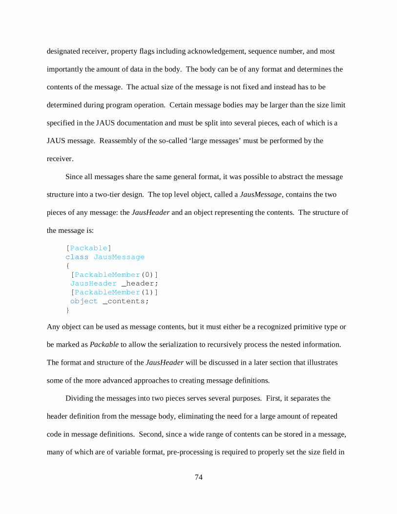
74
designated receiver, property flags including acknowledgement, sequence number, and most
importantly the amount of data in the body. The body can be of any format and determines the
contents of the message. The actual size of the message is not fixed and instead has to be
determined during program operation. Certain message bodies may be larger than the size limit
specified in the JAUS documentation and must be split into several pieces, each of which is a
JAUS message. Reassembly of the so-called ‘large messages’ must be performed by the
receiver.
Since all messages share the same general format, it was possible to abstract the message
structure into a two-tier design. The top level object, called a JausMessage, contains the two
pieces of any message: the JausHeader and an object representing the contents. The structure of
the message is:
[Packable] class JausMessage { [PackableMember(0)] JausHeader _header; [PackableMember(1)] object _contents; }
Any object can be used as message contents, but it must either be a recognized primitive type or
be marked as Packable to allow the serialization to recursively process the nested information.
The format and structure of the JausHeader will be discussed in a later section that illustrates
some of the more advanced approaches to creating message definitions.
Dividing the messages into two pieces serves several purposes. First, it separates the
header definition from the message body, eliminating the need for a large amount of repeated
code in message definitions. Second, since a wide range of contents can be stored in a message,
many of which are of variable format, pre-processing is required to properly set the size field in

75
the header. This would be very difficult to accomplish if the header was directly integrated into
the definitions. These messages were designed to function with the associated
JausMessageHandler which is responsible for certain aspects of advanced message processing.
Third, encapsulating the two pieces in an overarching object simplifies data passing and message
definitions because everything will be view as a JausMessage. This helps to reduce the
inheritance complexities that could arise from having a large number of separate formats. The
next section discusses how the definitions integrate with the message handler.
Custom Attributes and the Message Handler
Transport of messages requires conversion to and from a transport format. While this is
largely performed by the serialization library, it is still necessary to provide a specialized handler
that is responsible for overseeing the serialization process. Recall from Chapter 3 that a message
handler needs to be initialized with information that allows it to identify message objects. This
takes the form of a custom attribute that provides information about the particular message
definition to which it is attached. JAUS .NET defines an attribute called ‘JausContents’ that
stores the command code associated with the message body. Proper use looks like:
[Packable, JausContents((int)<commandCode>)] <messageDefinition>
Notice that the definition is both marked as Packable as well as being identified as contents for a
JausMessage. The JausMessageHandler uses this latter attribute to determine which data type to
process based on command code. The order and method for processing will be discussed in a
later section on the message handler.
Recall that the base message handler class automatically identifies all available message
definitions through the specified custom attribute. It checks for duplicate and conflicting
definitions using the command code information which acts as a GUID, ensuring that when the

76
derived message handler queries for a data type, it will only receive one value. In JAUS .NET,
the GUID for a message is its command code. This was selected for convenience since any
complete message begins with a header that identifies the contents by command code.
Raw Messages
One of the critical considerations in message design was how to handle the incoming
serialized representations of the data. Recognizing that all transport in JAUS is performed using
byte arrays, it was determined that the best approach was to create an intermediate message
format that bridged the gap between raw data and usable object. This object is called a
RawJausMessage and inherits directly from a JausMessage as illustrated in Figure 4-2. The only
difference between the two is that the raw form is specifically designed to use a byte array as the
message contents rather than a general object.
Figure 4-2. Inheritance and structure of RawJausMessage.
This change in format was made possible through an override of the property for header
access where the set functionality was changed to also pre-allocate the byte array during
deserialization. The following code snippet shows the implementation with the change boxed:
[PackableMember(0)] public override JausHeader Header { get { ... } set { base.Header = value; base.Contents = new byte[value.DataSize];}

77
}
The addition of a single line of code guarantees that the array for the contents of the message will
be large enough to hold the remainder of the data from the buffer. This knowledge is gathered
from the deserialized header and shows the standard way in which a pre-allocated array of
unknown length should be handled using the RCF.
This intermediate format simplifies processing of incoming messages. Since all messages
begin with a header of known format, that header can be deserialized safely every time. The
body is of variable length, so the raw data representing it must first be extracted from the
incoming buffer. Then this raw data can be deserialized once the message handler has
determined the actual data type that needs to be allocated. Storing the data for the contents in an
intermediate buffer allows error checking and additional processing to occur without having to
process the entire message. One additional benefit is that processing and reassembly of large
messages becomes extremely straightforward. As each piece of a large message arrives, it can
be stored along with the others until all of the pieces have arrived, at which point the message
can be reconstructed. RawJausMessage objects demonstrate only one aspect of message
definition in a very simplistic fashion. The next section shows several more detailed examples
that highlight various approaches to defining and handling complex data types.
Example Message Definitions
Many messages can be created using just the PackableMember attribute in the RCF, but
their format and contents would be inherently limited. Dealing with more flexible formats
whose size or contents may vary requires the use of more advanced features to control the order
and method of processing. This section presents a number of JAUS messages and data types
commonly used in these messages to illustrate how to develop more complex message

78
definitions. These same principles would apply to any architecture that requires flexibility in
message design.
JausHeader
Briefly discussed in the section on the development of the general message format, the
JausHeader data type is central to all messaging in JAUS .NET. It consists of sixteen byes of
specially formatted data that indicate features of the message, with an optional leading character
sequence. Figure 4-3 shows the memory order of the header segments. The “UDP Header” is a
fixed character sequence that is used to identify the following data as belonging to a JAUS
message. It is optional due to legacy implementation of JAUS in the lab where some messages
may not be preceded by the opening sequence. As a result, the implementation of the
JausHeader must accommodate processing of a string of known length. Discussion of the
approach used to solve this problem highlights not only how to handle strings, but also how to
deal with a particularly difficult issue arising from ill-formed message definitions.
Figure 4-3. Memory layout of JausHeader including optional header string.
The optional leading string is handled using a pair of pre-processing methods that are
invoked before any of the fields are processed by the serialization library. Since the leading
sequence may or may not exist, it is necessary to inspect the raw data without advancing the
source indexing. This is accomplished by shallow cloning the data source, attempting to unpack
just the string, and then actually unpacking the string if it exists. A shallow clone is a fast
operation that requires no copying of the source data and allows operations to be performed on
the copy without damaging the original. The code for determining the existence of the header
string looks like:

79
[OnUnpacking] void PreUnpack(Packer packer, object src) { string UDP_EXTRA = “JAUS01.0”; object tmpSrc = ((ICloneable)src).Clone(); string sniff = packer.Unpack(UDP_EXTRA, tmpSrc) as string; if (sniff != null && sniff.StartsWith(UDP_EXTRA)) {
packer.Unpack(UDP_EXTRA, src); _udpHeader = true; } else _udpHeader = false;
}
The string is being unpacked as a pre-allocated object, providing the packer with length
information in the process; all strings must be unpacked in this way as discussed previously. The
contents of the pre-allocated string do not matter, only the number of characters.
ReportGlobalPose
One of the most commonly used messages for vehicular operations, the ReportGlobalPose
message is used to report global positioning information. An interesting feature that also makes
this message ideal for performance testing is the large number of optional fields. Of the ten
fields present, only the first is required as its value determines which of the following members
need to be processed. Implementation requires the use of a dependency specification method
that accesses the data from the first field. The overall structure of the message is:
[Packable] [JausContents((int) EJausMessageType.REPORT_GLOBAL_POSE)] class ReportGlobalPose { [PackableMember(1)] JausPresenceVector _pVector; [PackableMember(2, Optional=true, DependencyIndex=0)] double _latitudeDegrees; <additionalFields> [DependencySpecifier] bool DepSpec(int index) { return _pVector[index]; }
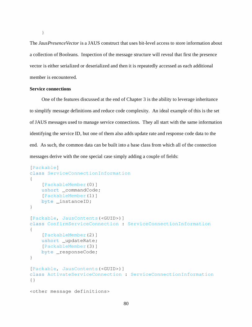
80
}
The JausPresenceVector is a JAUS construct that uses bit-level access to store information about
a collection of Booleans. Inspection of the message structure will reveal that first the presence
vector is either serialized or deserialized and then it is repeatedly accessed as each additional
member is encountered.
Service connections
One of the features discussed at the end of Chapter 3 is the ability to leverage inheritance
to simplify message definitions and reduce code complexity. An ideal example of this is the set
of JAUS messages used to manage service connections. They all start with the same information
identifying the service ID, but one of them also adds update rate and response code data to the
end. As such, the common data can be built into a base class from which all of the connection
messages derive with the one special case simply adding a couple of fields:
[Packable] class ServiceConnectionInformation { [PackableMember(0)] ushort _commandCode; [PackableMember(1)] byte _instanceID; } [Packable, JausContents(<GUID>)] class ConfirmServiceConnection : ServiceConnectionInformation { [PackableMember(2)] ushort _updateRate; [PackableMember(3)] byte _responseCode; } [Packable, JausContents(<GUID>)] class ActivateServiceConnection : ServiceConnectionInformation {} <other message definitions>

81
Only the ConfirmServiceConnection message requires additional code to add the special
fields. Every other message simply inherits from the base ServiceConnectionInformation class
and is immediately ready for serialization without the repetition of the field code. Not only does
the use of inheritance produce much cleaner code, but it also makes modifications easier. For
example, if the message definitions changed to also include a timestamp preceding the command
code, the only change required would be to add the appropriate field definition to the base class.
Implementation of the JAUS Message Handler
While the message definitions in the JAUS library allow data to be represented and
manipulated easily, the actual conversions and routing of these messages is performed by the
message handler. This section discusses the implementation details of the JausMessageHandler
and illustrates how to properly create a derived handler for system management using the RCF.
Three main areas require explanation: interfacing with the communications layer, processing of
messages and raw data both before and after transport, and finally the routing of messages either
to processing methods in the application or through the communications layer. It is important to
note that a message handler could be implemented in a different fashion from that described
here. The approach used in JAUS .NET was selected for its asynchronous abilities and is simply
a recommended design.
The JAUS message handler interacts with the transport layer in via two methods. The first
receives data from the communications interface; this is the raw, serialized data that was
received by the low-level communications. This data is processed by a dedicated thread that will
be discussed in the next section. The second method is used to process and send outbound
messages via the transport layer. The DataReceived method serves one purpose, to store a newly
received packet in a queue for processing by the internal thread that is running the
ThreadFunction discussed in Chapter 3. Once data have been enqueued, the thread is triggered

82
and allowed to proceed, following a standard multi-threaded synchronization approach. Both of
these methods are attached to the communications interface by the NMI.
Message processing an routing: Sending of messages is a two-step process that involves
pre-processing the data to determine the size and division parameters and then passing modified
versions of the messages to the communications interface for dispatch. Figure 4-4 shows the
overall sending process. The first step is the serialization of the message contents to determine
its size. Recall that the header specifies how much data follows in the buffer, a value that can
only be known by performing the conversion. If the serialized contents are small enough to fit
within the maximum packet size, a RawJausMessage is created from the header and newly
serialized contents and is sent to the communications interface for final dispatch.
If the message will be too large, the serialized contents are split into pieces each of which
will fit in the buffer and multiple raw messages will be sent instead. Each of these messages
consists of a modified version of the header and the section of the contents buffer to be sent. The
modified header contains information indicating the sequence number of the message piece and
whether it is a leading or trailing section. These flags will be used by the recipient component to
reassemble the large message in the correct order.
When sending, the communications interface creates a serialization packer and converts
the raw message into its final transport format, then sends it via the underlying low-level
connection. It is important to note that the JausMessageHandler has been completely geared
towards byte array format communications since the JAUS RA only specifies the byte
formatting.

83
Figure 4-4. Send method for JAUS messages.
Processing received messages is similar to the sending operation. Raw data is retrieved
from the message queue, the header is deserialized, then the appropriate action for the contents is
determined. If the message is not part of a large message (i.e. it is not one of several pieces) then
the contents are immediately deserialized using the type information retrieved from the internal
table. Recall that all message handlers have a hashtable of known message types built from the
assemblies and modules with which it was initialized. These types are stored by GUID and can
be rapidly retrieved at which point the message contents can be unpacked by type. If the
message is part of a large message, a raw message is created where the contents consist of the

84
last part of the buffer, still stored as a byte array. Once all of the pieces have arrived, the large
message is reassembled by first concatenating all of the buffer pieces together, then deserializing
the contents just like a normal sized message. Once the contents of a message have been fully
deserialized, the processing thread assembles a final message using the header and the new
contents. It then retrieves the list of message processors by GUID from the second hashtable and
asynchronously invokes each one. Figure 4-5 shows the process for unpacking messages while
Figure 4-6 illustrates the routing logic.
Figure 4-5. Deserialization of a JAUS message.
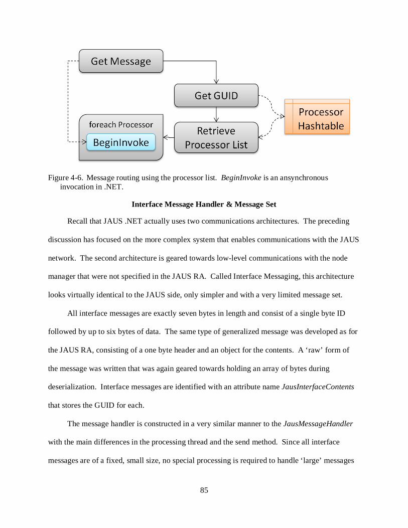
85
Figure 4-6. Message routing using the processor list. BeginInvoke is an ansynchronous invocation in .NET.
Interface Message Handler & Message Set
Recall that JAUS .NET actually uses two communications architectures. The preceding
discussion has focused on the more complex system that enables communications with the JAUS
network. The second architecture is geared towards low-level communications with the node
manager that were not specified in the JAUS RA. Called Interface Messaging, this architecture
looks virtually identical to the JAUS side, only simpler and with a very limited message set.
All interface messages are exactly seven bytes in length and consist of a single byte ID
followed by up to six bytes of data. The same type of generalized message was developed as for
the JAUS RA, consisting of a one byte header and an object for the contents. A ‘raw’ form of
the message was written that was again geared towards holding an array of bytes during
deserialization. Interface messages are identified with an attribute name JausInterfaceContents
that stores the GUID for each.
The message handler is constructed in a very similar manner to the JausMessageHandler
with the main differences in the processing thread and the send method. Since all interface
messages are of a fixed, small size, no special processing is required to handle ‘large’ messages

86
or even to set the message size like in JAUS. As a result, sending a message simply involves
handing the object to the communications interface.
Service Connection Manager
JAUS is a service-oriented architecture, so it relies heavily on the ability to create and
control the message flow between components. To this end, the Service Connection Manager
(SCM) was developed, enabling a component to easily add and remove connections to others
while simultaneously dispatching messages at variable rates. It also provides basic maintenance
features and the ability to monitor a connection’s health. The SCM is attached to both the JAUS
message handler and the interface message handler of the NMI so that it can receive connection
messages. It also dynamically adds and removes message processing methods on the JAUS
message handler to aid in monitoring of connections health. It is important to note that the health
monitoring is not the same as the component receiving the message for processing. It is still the
responsibility of the developer to ensure that one or more methods in the main application have
been marked as message processors for the particular type of message supplied. The SCM is
simply using the event-driven, asynchronous nature of the message handlers to monitor the
connections without interfering with application function.
Two kinds of connections exist, inbound and outbound. Inbound connections are those on
the subscriber side and are used to receive data from another component. Outbound connections
are those in a provider component and allow the application to send periodic updates to its
subscribers. Connections are tracked via two internal lists of time-stamped objects called Service
Connection Objects (SCO), one for inbound and one for outbound. These objects contain
information pertaining to service identification and the associated JAUS address, whether the
supplier or consumer.

87
Two threads monitor the connections and are only active if connections have been made.
To aid this, an event is attached to each service connection object that is used to signal
connection health. This event consists of one or more methods in the main application that will
receive error information. The inbound monitor iterates over the list of active inbound
connections and checks the timestamp of the last received message against the current time and
expected update rate. If too much time has passed since the last update, a warning message is
sent to the main application via the previously mentioned event. This allows a developer to
check the status himself and determine whether or not action is needed to correct the issue.
Outbound connections are monitored by a thread that checks the timestamp of the last sent
message against the current time. If enough time has passed, the current outbound message is
sent to the address specified in the time-stamped object. It is the responsibility of the developer
to update this message as appropriate. The SCM is simply responsible for sending messages on
time at set rates, not ensuring that the application is actually updating the information. This
behavior was selected since forcing the application to update at a particular rate could
unnecessarily tie a developers hands with respect to timing and operation.
Creation of a connection is an event driven process very much like the check-in ability of
the components. Inbound connections require a three-step process that involves first querying
the node manager for component information, then sending a connection request to the
component, and finally adding the connection to the list of connections and starting the inbound
monitor. A method named CreateInboundServiceConnection sends a request to the node
manager for the address of a component that can supply a particular kind of message. The
response sent back, called LookupAddressResponse, is processed by the AddressResponse
method that has been attached to the interface message handler. If a connection can be
88
established, this method sends a request to the target component and processes the response with
the ConfirmedConnection method that is attached to the JAUS message handler. This last
method is responsible for adding the new connection information to the inbound list, adding the
connection to the message handler, and finally starting the inbound monitor.
Adding an SCO to the message handler requires the use of the dynamic add feature
discussed in Chapter 3. Each SCO has a method named ProcessMessage that follows the form
needed to receive JAUS messages. It is added by creating a delegate called a
JausMessageProcessorCallback using the target method and attaching the command code for the
particular message type to be received. While it might seem that this approach is unnecessarily
difficult and that one could just add the MessageProcessor tag to the method, the dynamic nature
of the SCM prohibits it. An SCO needs to be able to monitor any JAUS message and the
MessageProcessor attribute only allows one message type to be specified for a method.
Therefore, the only way to ensure that data gets routed to the appropriate processors is to
dynamically add them to the message handler as the GUIDs become available.
Outbound connections are created when the ProcessConnectionRequest method receives a
CreateServiceConnection message. It determines if it can supply the message type at the desired
rate and then sends a response either confirming or denying the connection request. If the
request was accepted, a new SCO containing the destination address is created and activated.
When the outbound monitoring thread runs, it will check the timestamp on this SCO to
determine whether or not to send the current outbound message to the destination via the NMI.
Final Comments
The RCF provides the framework needed for easy deployment of a message-based
communications architecture. JAUS .NET implements architecture specific behaviors and
tightly integrates them using a combination of message handlers, low-level communications

89
interfaces, and a flexible message set. The derived handler was relatively simple to create
because it only needed to define two main methods that performed final conversions and routing
of data using the built-in information tables. The message set was easily designed and created
thanks to the flexible nature of the serialization core in the RCF. The code base is relatively
small when compared to other JAUS implementations and shows admirable performance. A
more complete comparison is made in the Results & Conclusions chapter. Overall, JAUS .NET
was extremely quick and easy to deploy and has great flexibility and modularity in design. Not
only does this make the architecture highly maintainable, but it makes end-developer usage
exceedingly simple. Thanks to the design of the RCF, a developer can rapidly deploy an
asynchronous, multi-threaded, event-driven JAUS component with only twenty lines of code.
This sort of development speed is rarely seen, but can be easily accomplished building off of the
RCF. The next chapter discusses some of the optimizations and design challenges faced when
developing the RCF for high efficiency and flexibility.

90
CHAPTER 5 PERFORMANCE OPTIMIZATIONS & DESIGN CHALLENGES
One of the biggest challenges in software development is producing high efficiency code
that can provide good performance while still being maintainable and easy to use. Proof of
concept implementations are commonly used to test the feasibility of an approach as was done
with the RCF. However, after the serialization routines were verified and tested, it became clear
that vast improvements could be made to the performance. This chapter presents the primary
optimizations that were made and the logic behind their development.
During development of the RCF it quickly became apparent that using the standard
reflective calls for data manipulation resulted in less than optimal performance. In fact, it was
determined that using a purely reflective approach could be as much as two orders of magnitude
slower than targeted, optimized code. This led to further investigation into how to circumvent
the costly aspects of the reflective environment while still benefitting from its inherent
flexibility. Eventually a combination of methods were used to drastically improve performance
over the original implementation. These included modified data structures for repetitive access,
a custom developed data format for rapid collection and retrieval of data, and dynamically
generated, targeted methods for data manipulation that outperformed the reflective calls by
nearly a hundred fold. To understand how these modifications work and why they provide such
an improvement to performance, it is first necessary to look at how the .NET Framework
actually functions at its lowest level.
Inner Working of .NET
Any .NET application runs inside the Common Language Runtime (CLR), which is
essentially a virtual machine responsible for the memory management and operation of the
environment. A .NET assembly is actually comprised of binary code called the Common

91
Intermediate Language (CIL). This is a compiled version of whatever language in which the
original application was written. In a very real sense, the CIL is the true language in which .NET
operates. C#, VB .NET, C++ .NET, and other languages are simply higher level languages that
are interpreted by the compiler and converted into CIL. At runtime, the CLR interprets and
compiles the CIL assembly to generate binary instructions targeted at the particular operating
system, hardware combination in which the environment is operating. This is called Just In
Time compilation (JIT) and is very similar to how the Java Virtual Machine operates and is the
reason for which a .NET assembly can be used with any .NET language. Thankfully, virtually
any application can be written using one of the high level languages, such as C#. Attempting to
write a full assembly using CIL would be like developing a native library using assembly code.
Reflection
As a managed environment, .NET imposes a certain amount of overhead on operation with
the memory management, JITs, and scanning of assemblies. In general this has a relatively small
impact on performance, but for certain operations the cost can be quite high. The two major
areas that can suffer in performance are pure reflective calls and certain array operations. This
section discusses the nature of reflective calls and investigates the overhead involved.
Reflective calls are any method invocations of the reflective environment that are used to
retrieve information about an object or to modify properties of the object. These include
retrieving the data type, inspecting custom attributes that have been attached, and obtaining
information about members of the object including methods and fields. It is even possible to
access the members via reflective calls, allowing a developer to manipulate an object without
prior knowledge of its behavior. This is how the RCF is able to generalize the message routing
and serialization of messages.

92
Certain commonly used reflective calls, such as data type retrieval, have been heavily
optimized to minimize the performance impact. However, many others have not and instead rely
on a large amount of background processing to operate. These include:
• Custom attribute retrieval. • Field/Property access. This includes setting and retrieval of values. • Method invocation. Any method can be invoked if given the proper arguments.
For many of the non-optimized calls, the application relies on the reflective environment to
read data from the assembly, find a match based on the particular call, then determine what data
needs to be routed and how to do it. Needless to say, this is extremely computationally
expensive and results in terrible performance. The best way to avoid this penalty is to minimize
the number of calls to costly methods. This proved to be a challenge as the only information
about message and application structure came from reflective information. However, it was
possible to circumvent the problem by dynamically generating optimized, pure CIL methods at
runtime. The next section discusses the true form of .NET methods and the basics of operation
in the CIL to provide the basis for discussion of the actual optimizations performed in the RCF.
Methods and Microsoft Intermediate Language
Like most other environments, the CLR uses a call stack for program operation. Data is
pushed onto the stack to make it accessible to methods that are called. These methods pop the
elements off of the stack then perform their own processing using a stack. This means that all
methods are of the same form. As shown in Figure 5-1, typical operation follows these steps:
• Data is loaded onto the stack in the order in which it should be processed. • A method is called. • The arguments are popped from the stack and passed to the method. • The method runs. • Arguments and other data are loaded onto the stack as needed. • Other methods are called. • If the method has a return value, that data is pushed onto the stack.

93
Figure 5-1. Stack operations during method calls.
Two types of methods exist in standard .NET languages: static and instance. Instance
methods are those that can be called from an instance of an object and have direct access to its
data. Static methods are only associated by name for organizational purposes, so they cannot
directly manipulate the data within an instance. This logical separation is designed for
operational safety and is only restricted to the high-level languages like C#. However, inspection
of the CIL code for an instance versus a static method will reveal nearly identical structure.
While an instance method is invoked using a direct call associated with an object, the actual form
is differs in memory. The general form and usage of instance methods are:
C# Definition: <type> <instMethodName>(<argList>) <methodBody> C# Usage: <objectName>.<instMethodName>(<argList>); CIL Definition: <type> <instMethodName>(<object>, <argList>) <methodBody> CIL Usage: <instMethodName>(<objectName>, <argList>);
Looking closely at the C# and CIL versions of the same method, one will notice that the
only difference lies in the positioning of the object whose method is being invoked. In other

94
words, the compiled CIL version of an instance method is actually a method that is passed a
reference to the instance object as well as the defined argument list. By contrast, a standard
static method is not passed a reference to an instance object, denying it access to the object’s data
and features. The format looks like this:
C# Definition: <type> <staticMethodName>(<argList>) <methodBody> C# Usage: <objectType>.<staticMethodName>(<argList>); CIL Definition: <type> <staticMethodName>(<argList>) <methodBody> CIL Usage: <objectType>.<staticMethodName>(<argList>);
Overall, the structure of static and instance methods are very similar with the only
difference being the actual parameter lists being used. However, there exists another special
form of static methods that take on an identical form to the instance methods. Extension
methods are static methods that can be used in the same way as instance methods.
C# Definition: <type> <extMethodName>(<argList>) <methodBody> C# Usage: <objectName>.<extMethodName>(<argList>); CIL Definition: <type> <extMethodName>(<object>, <argList>) <methodBody> CIL Usage: <extMethodName>(<objectName>, <argList>);
Notice that the form and usage of an extension method is indistinguishable from that of an
instance method. The restriction on data access is imposed by the compiler, not the environment.
This means that in reality, any static method could be used for data access and manipulation in
an object instance if properly created. This can be accomplished using what are known as
dynamic methods, runtime generated CIL code that can then be interpreted and JITTED by the
CLR. This is equivalent to dynamically generating assembly code to modify an application’s

95
behavior at runtime and is possible thanks to the ‘Emit’ capability of the reflective runtime in
.NET. The next section describes in detail how a combination of revised data structures and
dynamic methods were used to drastically speed up the serialization routines in the RCF.
Reflective Optimizations
As discussed in a previous section, several reflective calls are extremely costly to use due
to the overhead and the only way to avoid this penalty is to minimize their usage. These
methods can be split into two general categories: those that retrieve structural information and
those used to access data and functionality in objects. One will recall that during serialization in
the RCF, the first step is to determine the structure of the object that is to be processed. It is
highly likely during operation that the same type of object will be processed many times. As a
result, storing structural information about known object types would alleviate the need for
repeated calls to attribute retrieval methods. The other set of methods are used to access data in
objects and to invoke instance methods. As was discussed in the previous section, it is possible
to create targeted methods that perform the same functionality but far more efficiently.
Storing Message Structure
The first big step towards an efficient serialization implementation involved the storage of
information about previously encountered message types. Since the structure of messages will
not change during operation, it was reasoned that the structure only needed to be collated once.
Repeated processing of any particular data type could then be performed on this compiled
information rather than gathering it each time. The most efficient form of storage for this
approach was to use a hashtable whose keys were the data types and values were a custom object
containing structural information. Named PackingInfo, the storage object contains information
about any member fields that need to be processed along with the special processing methods.
These include the pre, mid, and post-processing methods along with any dependency specifiers.

96
When the serialization library processes an object, retrieves the packing info associated
with that data type from the hashtable. If the data type is being encountered for the first time,
reflective calls are made to retrieve the structure of the object based on member type and
attribute. This is the only time during program operation that the expensive reflective calls are
made. The structural information is then stored in one of several collections and sorted based on
the indexing values in the attributes. This combined data is added to the hashtable for quick
reference when the data type is encountered again. The PackingInfo class includes eight
collections of specialized methods:
• Packable members. These provide access to the raw data in an object.
• Specialized packing/unpacking methods. These are the pre, mid, and post-processing methods discussed previously. Six collections, one each for the different types.
• Dependency specifiers. These are the methods for processing optional fields.
Once the packing info for a data type has been retrieved, the packer processes the data as
described in Chapter 2. Access to member fields and methods is performed through the info
objects stored in the packing info which provides easy centralized access to all custom features
of an object. Originally, access to members was made via reflective calls using the information
in the packing info objects. However, as previously discussed, these are extremely slow methods
and suffer a large performance impact. As a result, is was determined that a more efficient
approach was needed that still provided the flexibility to handle any structure. The answer came
in the form of targeted dynamic methods.
Dynamic Methods
As previously discussed, methods all have the same basic form and usage in CIL, differing
only in argument lists. A generalized dynamic method that provides access to members of an
object will take one of three forms depending on whether it is to be used for field access or

97
method invocation. Field access has two possibilities, getting a value and setting the member.
The dynamic methods for field access will look like the following where ‘arg0’ is always the
object whose member is being accessed:
Get: object <methodName>(<arg0>) ldarg.0 ldfld <fieldInfo> ret Set: void <methodName>(<arg0>, <arg1>) ldarg.0 ldarg.1 stfld <fieldInfo> ret
Notice that in both methods, the first step is to load the target object onto the stack
providing direct access to its members. If the field data is being retrieved, the next step is to load
the field using the FieldInfo stored in the PackingInfo class. This value is then returned by the
method. If the field is having a value assigned, the second argument ‘arg1’ is loaded onto the
stack and then set, again using the FieldInfo. While the above example is not exactly
syntactically correct, it shows the necessary structure for any get/set methods. In fact, if one
were to create two C# functions GetField() and SetField(value), the disassembled forms of these
methods would look virtually identical. As a result, the above approach is literally the fastest
way to perform field access via a method.
By the same token, dynamic methods used to invoke other methods, such as those used for
special processing by the RCF, follow a similar structure:
object <methodName>(<arg0>, $methodArgs$) ldarg.0 $load the ‘methodArgs’$ call <targetMethod> ret

98
The method loads the target object onto the stack, followed by any additional arguments that
must be passed to the target method. This forms the exact argument list needed to invoke the
target. The target is then called and any result is returned. This is exactly equivalent to:
object WrapperMethod(object source, <argList>) { return TargetMethod(source, <argList>); }
It should be clear now how targeted, dynamic methods can be dramatically more efficient
than reflective calls. They are comprised of the absolute minimum, optimized instruction set
possible in .NET, completely avoiding the overhead of the reflective environment. The only
remaining questions are where these methods are stored and how they are invoked. The answer
to the first question is that each dynamic method is stored in the same object as the packing
information for the member it targets. For example, the methods to retrieve and set a field are
encapsulated in an object that also contains the FieldInfo and PackableMember attribute for that
field. In this way, all of the data is consolidated into one location and is easily accessible. The
methods are automatically created when the descriptor object is created, isolating the conversion
logic from the rest of the system. This has the added benefit of great flexibility in use since the
Packer class does not require any special routines to gain access to this functionality.
Utilization of dynamic methods is accomplished through the use of delegates, which were
mentioned in Chapter 2. Delegates were defined for field access, property access, packing
method invokes, unpacking invokes, and dependency specifiers. The allocated delegate objects
were made publicly visible, allowing them to be called using the same syntax as regular method
calls. For example, setting a field would look like:
<fieldAttribute>.SetValue(<object>, <value>);

99
where SetValue is actually the delegate pointing to the dynamic method generated specifically
for the object and field in question. Also note that the code is extremely clean and simple to use
which results in more maintainable source.
BytePacker Optimizations
The use of dynamic methods and persistent storage of message structures removed the
major bottlenecks on serialization performance. However, one last modification was made that
further improved the performance of object serialization with regards to byte-based
communications. Since the BytePacker is a targeted implementation of the base ‘Packer’ class,
testing was performed early on to determine the best method for storing and retrieving the raw
data that it was handling. It was quickly determined that the best .NET object to use was a list of
bytes which had two major advantages over other approaches. First, it was self-regulating,
making it extremely simple to use without concern for unhandled exceptions and memory issues.
Second, it was at least an order of magnitude faster than any other data structure available.
After the other optimizations were made, the raw data storage question was revisited to see
if a new approach couldn’t improve on the .NET implementation. As such, the replacement
storage needed to be faster to use than the list while still being as safe and easy to use in the
limited context of serialization. The main reason that the lists in .NET do not operate as quickly
as might be expected is that they are still fully managed objects. Any operations they perform
must still be monitored and policed by the garbage collector and memory manger in the
framework. Even so, they are still highly optimized and extremely fast. The only way to
effectively improve on the performance is to bypass the garbage collector.
It is possible to run unmanaged code in .NET applications by declaring a region as ‘unsafe’
which tells the environment that the marked section is responsible for its own memory
management. When combined with direct memory access, unmanaged code in .NET can run

100
nearly as fast as a pure unmanaged equivalent. A hybrid data object was developed that used
managed memory for storage and scaling logic, but used unmanaged memory copies to provide
faster operation. The object still has the ability to increase storage capacity as a list does and can
efficiently provide access to the data inside. Also, it is completely self-regulating, allowing the
user to simply add new data during operation. Other features of lists, such as sorting and
removal of data, were not included as they were deemed unnecessary for the task at hand. In the
end, the new data store operates six to ten times faster than its list counterpart while requiring
virtually no change to usage.
101
CHAPTER 6 RESULTS AND CONCLUSIONS
The Reflective Communications Framework was designed to address the needs of
distributed system development and provide a core toolset to rapidly design and deploy any
communications architecture. It defines tools to create the three major pieces common to all
distributed systems: low-level transport protocols, data routing and interpretation, and the data
set used for communications. Together, these advancements in the field of robotics and
distributed system design enable a developer to easily implement a communications system in a
highly modular fashion. This has the added benefit of making the final product simple to modify
and update while maintaining performance levels.
Major Features
Standardizing the low-level transport provides a level of abstraction needed to simplify and
generalize system design, effectively separating the complexities of communications from those
of architectural logic. Properly used, an architecture built on the RCF can be designed to operate
on a wide range of communications layers. Most other distributed systems are tightly integrated
with only one or two communications protocols, requiring massive modifications to move to a
new format. An RCF-based architecture has the potential to avoid this common pitfall and the
associated additional costs.
The second feature of the RCF, generalizing the data routing and interpretation, has a
number of benefits in distributed system design. First, the final implementation can be extremely
easy to use, enabling rapid development of applications and reducing development time and
costs. This is well demonstrated in the JAUS .NET reference implementation which allows a
developer to create a fully JAUS compliant component in a matter of minutes. Second,
centralizing the core logic makes modifications and maintenance much simpler. Rather than

102
having a large number of pieces interacting to perform data routing tasks, everything can be built
into one location with very little code. For example, the core message routing and conversion
code for JAUS .NET is only about three hundred lines including comments. Third, a great deal
of flexibility is inherent to the RCF message routing system, allowing a derived system to
automatically modify its behavior and knowledge set during operation. Whereas most
distributed systems only reorganize themselves on the client or application level, an RCF-based
system can just as easily rearrange itself at the sub-component level with individual applications
redefining their behavior.
The third major piece of the RCF, the reflective message set, brings a new level of control
over serialization processes that has not been seen before. While other systems use standardized
serialization techniques that target only one or two formats, the RCF allows a developer to create
a single message definition that can be converted into virtually any format. All that is required is
to properly develop a serialization class that targets the particular format desired. This class is
simply an extension of the core that provides the standardized interpretation of message
structuring. RCF-based messages do not require the large amounts of additional processing code
so common to other systems, reducing their complexity and making them easier to use and
maintain.
The core library of JAUS .NET has been written in less than 14,500 lines of code, of which
approximately 2700 were the architectural behavior. The rest is comprised of definitions for
over 150 separate messages. The resulting product is easy to use, allowing a simple JAUS
component to be deployed in minutes rather than hours. Previous implementations of JAUS
have been difficult to maintain and modify and even more difficult to utilize effectively. The

103
RCF itself is only about 2750 lines of code, yet it defines the core features needed for any
distributed system.
Performance
Not only is the RCF extremely compact, but a great emphasis was also placed on the
system performance. This includes both the serialization processes as well as the multi-threaded
aspects. A number of pieces of the RCF are multi-threaded or asynchronous in nature, often to
avoid potential dead-locks and other slowdowns. This is necessary for responsive behavior as
any distributed system will need to deal with multiple streams of data simultaneously. Since the
asynchronous and event-driven model is built into the RCF, a developer can instead focus on
getting the best performance out of each individual section, rather than trying to streamline a
single process. The event-driven model also simplifies application development as they can be
written as highly modular components with extremely flexible structure. This is directly related
to the centralized data routing and interpretation discussed earlier.
The serialization library is the component that received the greatest attention to
optimization as data conversion is generally the slowest and most costly operation in any
communications system. The resulting implementation is highly streamlined and extremely
efficient, imposing very little overhead on application performance. Both serialization and
deserialization were tested thoroughly to determine and remove the bottlenecks. Since JAUS
.NET acted as a demonstration of the RCF’s capabilities, one of the most common messages was
used for testing.
The ReportGlobalPose message was selected for two reasons. First, it is a common
message used in JAUS systems and contains potentially time-sensitive data. Second and more
importantly, it contains a large number of optional fields as previously discussed. As such, it
makes an ideal candidate for testing mid-process method invocation as well as numerous small

104
conversions. Three separate classes of tests were performed as illustrated in Figures 6-1 through
6-3 at the end of the chapter. These included simplified packing to verify proper message
conversion, more complete packing operations as would be performed by the message handler,
and finally unpacking operations. The last two tests closely approximate the speed at which the
JausMessageHandler would operate without heavy system load and show the best-case
performance. All tests were performed on an Intel Core 2 Duo 2.13 GHz machine with 4 GB of
RAM.
When the RCF was first implemented, it used a number of inefficient approaches that were
discussed in detail. During the early stages this was of little concern since the focus was on
implementing the serialization algorithm properly. However, after the first speed tests were
performed, further development shifted to optimizing the performance. Initially serialization of a
global pose message required approximately 2.5 ms to complete. Addition of the internal
hashtable for known data types and the introduction of dynamic methods reduced this drastically
to an average of about 40 µs. The final step of implementing a high efficiency data structure to
hold the raw data further reduced this time to only 22 µs, yielding a net performance increase of
110 fold. Under optimal conditions this number has dropped as low as 19 µs, though this is
highly dependent on current system load.
Deserialization with the RCF is also extremely fast, though it is somewhat slower than the
serialization. This is likely due to the higher cost of bit conversions back into the original data
types. Even so, deserialization of a global pose message still averages only 52 µs.
The test shown in Figure 6-1 was introduced to help quantify the additional overhead of
the intermediate packing operations required for JAUS messages. Notice that it eliminates the
intermediate step of packing just the message contents and creating a raw message. This reduces

105
the processing time to just that required for serialization of the header and contents without the
overhead of copying the raw contents into the final buffer. Average serialization time for this
slightly reduced test averaged 20-21 µs, a miniscule difference when compared to the more
complete approach. The time difference is essentially a measure of how long it takes for the
custom high efficiency data buffer to copy the intermediate contents into the final buffer. The
data buffer is extremely fast and introduces very little overhead to standard conversion
operations.
One of the concerns expressed by many developers is the performance impact of a
managed environment such as .NET. To investigate this issue, serialization of several messages
was tested using both JAUS .NET and an older, native implementation that has been in use for
several years. Table 6-1 shows the average time for processing of ten thousand of each message.
Table 6-1. Serialization performance of native vs. managed environments. Message JAUS .NET (µs) Native (µs) Ratio ReportGlobalPose 21.64 3.69 5.86 ReportWrenchEffort 21.44 4.44 4.83 ReportCameraCapabilities 24.17 4.39 5.51 ReportCameraPose 22.40 4.17 5.37
It comes as no surprise that the processing time in the managed .NET environment is
consistently slower than its native counterpart. However, closer inspection of the data reveals
that the on average, the managed implementation is only 5-6 times slower than the native
libraries. Considering that the times are relatively low in both environments, the performance
impact of serialization is nearly negligible in many systems. When weighed against the ease of
development using the Reflective Communications Framework and the greatly improved
flexibility of design, the slight overhead required to run in a managed environment becomes a
non-issue for most systems.

106
Final Comments
Overall, the optimizations to the RCF produced incredible performance gains. Even
though the system runs in the managed .NET framework, it shows speed on par with or faster
than native code systems. However, it has the advantage of being a highly flexible and usable
framework with capabilities that would be extremely difficult or even impossible to implement
in native languages.
The Reflective Communications Framework provides a powerful toolset that can be used
to develop a wide range of communications architectures and distributed systems. It addresses
the needs common to all distributed systems in a compact, high efficiency package that has the
additional benefit of being cross-platform. The .NET framework is available on all operating
systems either as .NET in windows or as Mono in Linux and Mac systems. In the same way that
Java applications have long been easily deployed on a wide range of systems, RCF-based
applications will show the same level of flexibility. The RCF is a unique and novel approach to
the problem of rapidly developing distributed systems that can run on a wide range of platforms,
yet remain maintainable and show good performance. It is now possible to easily meet all of
these requirements.

107
Figure 6-1. Simplified speed testing for a JAUS message.
Figure 6-2. Simulated packing as performed by the message handler.
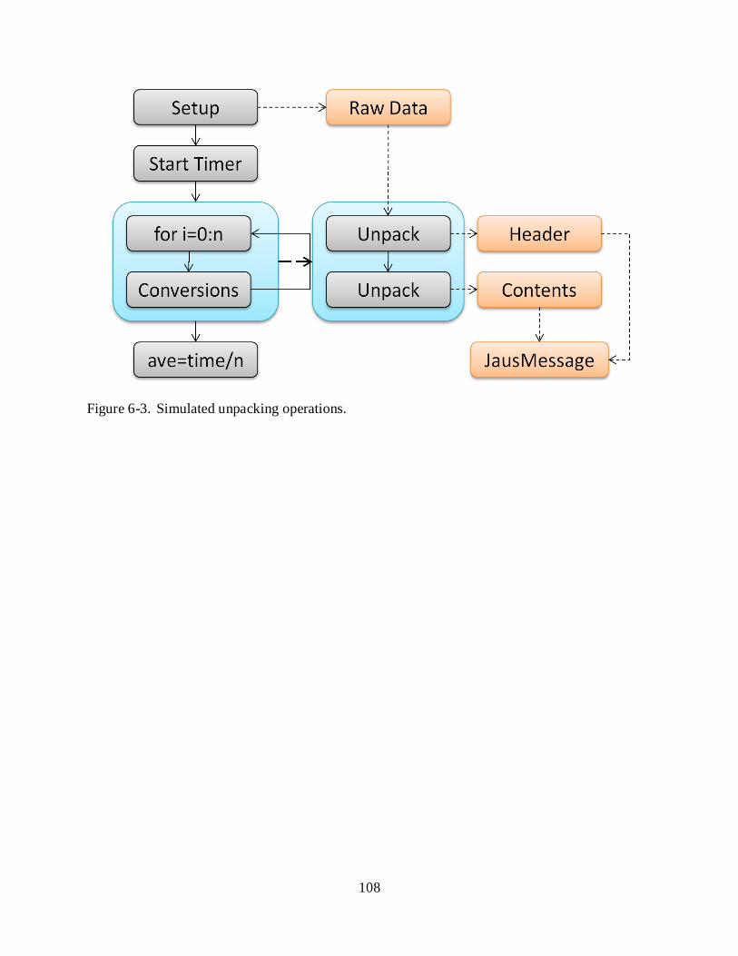
108
Figure 6-3. Simulated unpacking operations.
109
APPENDIX A REFLECTIVE COMMUNICATIONS FRAMEWORK PACKER DOCUMENTATION
Introduction
One of the key features of the Reflective Communications Framework (RCF) is the
generalized serialization protocol that it defines. It allows a single message object with specific
formatting needs to be processed to and from virtually any format. This is accomplished with
serialization objects that derive from a common abstract base class which defines the general
serialization protocol. The main dissertation presents a very thorough discussion of the packer
design, serialization protocol, and the implementation of a derived class called BytePacker. This
document is meant to discuss in greater detail certain considerations and requirements when
implementing a customized derived packer. Several issues could not be covered in the main
dissertation and are presented here as supplemental material for developers.
Required Overrides and Design Considerations
The base Packer class defines the overall serialization algorithm and is responsible for
invoking mid-processing methods and retrieving or setting member data. The packing algorithm
is meant to be recursive, but the main implementation only handles processing of one level of an
object. The actual conversion and storage processes must be defined by the derived classes
along with the recursive calls themselves. It might seem counter-intuitive that the recursion
would be separated into the derived class, but later explanation will make clear why this is a
desirable and in many cases necessary trait.
Parts of the BytePacker implementation and will be discussed to illustrate certain design
decisions and their impact on performance. These include recursion, type versus object
processing, how to handle complex data types, and an optimized internal storage mechanism.
All together, the optimizations increased processing speed by up to fifty fold.

110
Five methods must be overridden to fully implement a packer: AddNewValue, PackNew,
FromSourceType, FromSourceObject, and GetFinal. Each of these is responsible for different
aspects of the conversion process and each needs to be carefully written. PackNew,
FromSourceType, and FromSourceObject perform conversions during serialization and
deserialization and determine the recursive behavior of the packing. They determine what data
types can be handled and exactly how they are converted. As a result, these three methods are
highly sensitive to processing order and must be very carefully designed. Also note that while
most packing classes will only handle standard data types, it is possible to create a packer that
only interprets custom types. While this would break the general nature of the packer, certain
extremely complex problems can be solved that would otherwise be impossible to tackle. A
theoretical example will be discussed later.
The performance of the base class has been heavily optimized. The serialization process is
usually the most costly and time-consuming part of communications, so it is imperative that the
derived methods be written in as efficient a manner as possible to ensure fast operation. Another
performance consideration is the internal storage of the serialized data. Efficient storage and
retrieval of processed data is as important as the conversion processes themselves and can have
an enormous impact on performance. Each of these issues will be discussed in detail in the
following sections.

111
PackNew
Figure A-1. Typical implementation for PackNew.
PackNew is called by the base packing class for every single member conversion during
serialization. As a result, it must be written to handle every single data type that the packer will
need to process. Figure A-1 shows a typical implementation for PackNew that considers both
standard and iterable data types. Unless an unusual packer design is required, it is highly
recommended to follow this structure. It guarantees proper recursion and proper handling of the
most common types that will be encountered. Several steps are performed in this method.
First, the method needs to check if the data type has been marked as Packable, indicating a
custom definition. If a custom type is detected, a new packer should be allocated and used to

112
serialize the data. This creates recursion in the processing as the new sub-packer will perform
operations on the members of this nested object. It is important that this be the first check in the
method as it is possible to create a custom type that is also iterable. This potential conflict will
be discussed later.
Conversion of standard data types, such as integers and doubles, will likely be performed
using environmental tools. For example, the BytePacker implementation uses the BitConverter
class built into .NET. A string based packer might use the ToString method. Other formats
might need to implement custom converters.
The final section of PackNew will likely be processing of iterable data types, such as arrays
and lists. These derive from the IEnumerable interface and allow an application to easily iterate
over their elements. Notice that the process for converting an enumerable type is very similar to
the general packing implementation. It involves creating a local buffer like that of the main
packer, performing a PackNew on each element, storing this result in the local buffer, and finally
assembling the serialized representation of the whole object. It is possible to have an enumerable
collection of Packable objects, so this call to PackNew causes recursion that allows processing to
any depth.
IEnumerable Conflicts: It was briefly mentioned that the check for a Packable object
should be performed before any others to avoid potential conflicts with an enumerable type.
Suppose that an object has been marked as Packable but also allows iteration over its elements.
If it were to be processed as an enumerable type, then each element individually would be
packed. Two possible problems could occur. First, suppose that the object contains a number of
members that need to packed in addition to the iterable elements. These members will never be

113
processed, so the serialization will be incorrect. Second, even if the conversion is technically
correct, deserialization will encounter issues.
The packer will deserialize the raw data in the same order that data was packed using the
known types from the super class. This means that when the section of the array corresponding
to the object is encountered, the packer will attempt one of two approaches depending on the
implementation of the FromSourceType and FromSourceObject methods. One, it may try to use
the packing information for the object to deserialize each of its members, which may not have
even been packed. Two, it may try to allocate an IEnumerable data type, which is technically
impossible. This means that no object will be allocated, the data will not be deserialized, and
finally that position in the raw data buffer will be offset, preventing the rest of the deserialization
from proceeding correctly.
While PackNew handles serialization of all data types, two separate methods are required
for deserialization. The next two sections discuss the requirements for FromSourceType and
FromSourceObject.
Deserialization Methods
The current implementation of the Unpack method in the base Packer class has two forms.
One defines the actual unpacking algorithm and operates on an instance of an object. The other
one attempts to allocate an instance of a data type using Assembly.CreateInstance then passes
this object to the main Unpack method. However, it does not support passing of parameters to
the constructors, requiring that any data type have a dimensionless constructor. While this may
seem like an inconvenience, it was necessary for several reasons.
Consider three commonly used data types: arrays, strings, and lists. Each of these are
multi-element types, but they require dramatically different methods of initialization. An array’s
length (or lengths for multi-dimensional arrays) must be specified at creation. A string can be

114
created with no elements or many depending on the constructor used. A list is simply created but
contains no elements unless it was initialized with an IEnumerable object of matching type.
Recall that both the packing and unpacking processes use the data type of the member to
perform conversion. This data type, as retrieved by reflection, does not contain any information
about the length of a multi-element object. The only way for this information to be known
would be if another part of the message object in question could supply it when needed.
Generalizing the passing of these parameters would actually complicate message design as
developers would be required to understand how to use the CreateInstance method.
In addition, the code required to handle simple data types, such as a list, would be more
complicated than the current pre-allocation approach as extra methods and temporary storage
members would have to be included. Testing of both approaches has been performed and using
pre-allocation is actually three times faster than passing constructor arguments and invoking
additional methods, which may be related to the cost of invoking Assembly.CreateInstance.
In the interest of performance and maintainability, the current approach was selected that
requires certain data types to be pre-allocated. This has the distinct advantage of directly
providing the size and format information for a member via the object itself. The packer can
then iterate over the individual elements, extracting and assigning values using recursive calls to
the Unpack method. To accommodate deserialization both by type as well as by pre-allocated
object, two methods must be implemented by derived packing classes: FromSourceType and
FromSourceObject.
FromSourceType
FromSourceType is called when a member has not been marked as a pre-allocated object.
It will likely only handle the most basic data types, such as floats, and non-allocated members
that are Packable. Figure A-2 shows the recommended layout for the method.

115
Figure A-2. FromSourceType layout.
FromSourceObject
FromSourceObject is called for members that are marked as pre-allocated including arrays,
strings, and lists. Other data types can be processed here as well if required by the specific
format. Strings can likely be handled using conversion methods in .NET, such as
Encoding.ASCII.GetString. Lists require simple iteration, unpacking each element and assigning
it to the appropriate location. Nested lists are not a concern as the base unpacking method has
error checking built in to accommodate pre-allocated, non-packable objects. Arrays are the only
common data type that require special consideration since they can be many levels deep.
However, they can be handled with a simple recursive algorithm as follows:
// Call this method to start processing. void UnpackArray(object src, Array objArray, Type elementType) { int[] indexes = new int[objArray.Rank]; UnpackArray(src, objArray, elementType, 0, indexes); } // This method handles the various levels. void UnpackArray(object src, Array objArray, Type elementType,
int dim, int[] indexes) { // Iterate over this level’s elements. for (int i = objArray.GetLowerBound(dim);
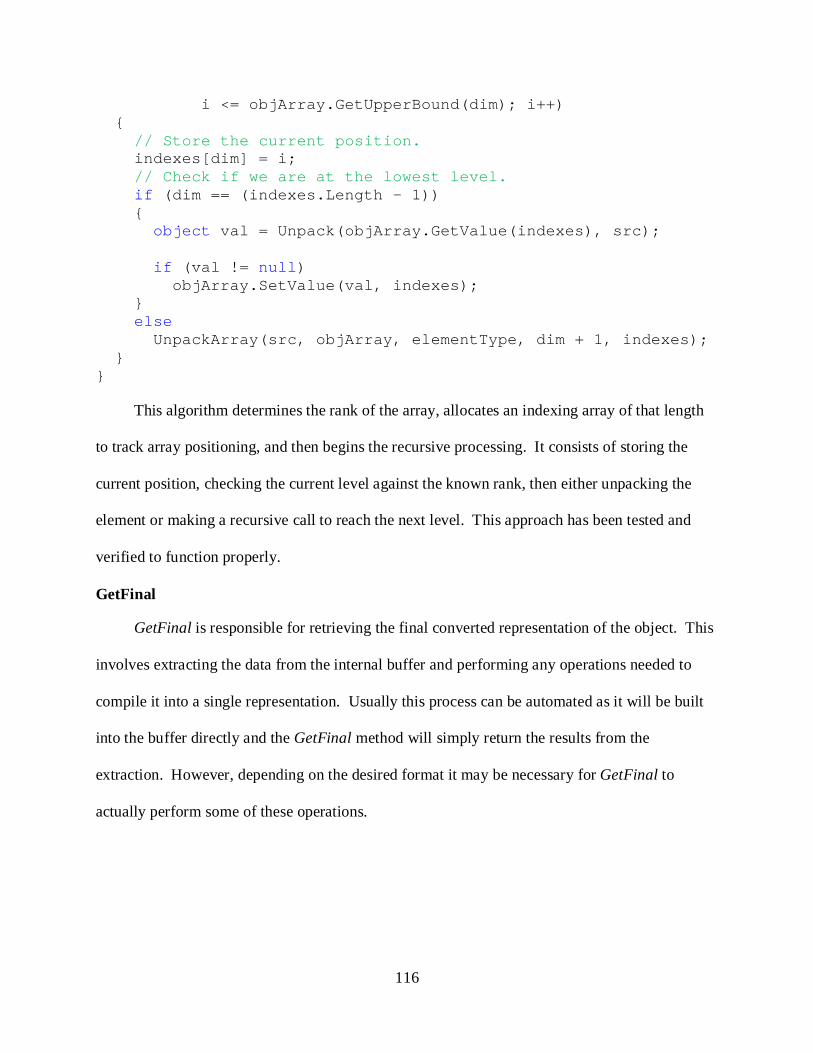
116
i <= objArray.GetUpperBound(dim); i++) { // Store the current position. indexes[dim] = i; // Check if we are at the lowest level. if (dim == (indexes.Length - 1)) { object val = Unpack(objArray.GetValue(indexes), src); if (val != null) objArray.SetValue(val, indexes); } else UnpackArray(src, objArray, elementType, dim + 1, indexes); } }
This algorithm determines the rank of the array, allocates an indexing array of that length
to track array positioning, and then begins the recursive processing. It consists of storing the
current position, checking the current level against the known rank, then either unpacking the
element or making a recursive call to reach the next level. This approach has been tested and
verified to function properly.
GetFinal
GetFinal is responsible for retrieving the final converted representation of the object. This
involves extracting the data from the internal buffer and performing any operations needed to
compile it into a single representation. Usually this process can be automated as it will be built
into the buffer directly and the GetFinal method will simply return the results from the
extraction. However, depending on the desired format it may be necessary for GetFinal to
actually perform some of these operations.

117
AddNewValue
AddNewValue is responsible for copying serialized data to the internal buffer. It is called
after the packer has processed and converted a member of a message object. Typically this will
be a very simple method that passes the data to the buffer for final storage.
Internal Storage
Optimizations to the internal storage should be the last step in packer implementation. It is
vital to optimize the rest of the conversion processes and thoroughly test stability before
modifying or even replacing the buffer. During serialization, the processed data needs to be
stored until such time as the packer must return the overall results in the GetFinal method. The
most important feature of the internal storage needs to be speed of data movement. The faster
data can be added to and finally retrieved from the buffer, the more efficiently the rest of the
serializer will run. It is impossible to present a general approach that will answer the need of all
serialized formats, but certain common questions can be considered.
First and foremost is the question of internal format itself. Ideally this should be as close
to the final serialized representation as possible. Not only does this simplify final conversions,
but it also reduces the amount of additional processing required to assemble the final output. It
may not always be possible to avoid a segmented representation, but it is preferable to use a
continuous buffer to which data added linearly.
The second issue is how the data is actually copied to the buffer. For initial
implementations it may be desirable to use the data types supplied by .NET. They are relatively
fast and extremely easy to use, allowing the developer to focus on the stability and performance
of the rest of the implementation. This approach has the added benefit of allowing the developer
to identify the features that are most convenient or necessary for a buffer. Only this minimal

118
feature set needs to be written for the replacement buffer, reducing the complexity and time
required for the changeover.
The BytePacker implementation in the RCF is an excellent example of how this process
was applied. When the class was first implemented, basic speed testing was performed to
determine the fastest .NET data type to use for dynamically building an array of bytes. It quickly
became clear that the best approach was to use a List<byte>, which was nearly thirty times faster
than other types. It had the additional advantage of being extremely simple to use, allowing an
array of bytes to be directly added. Generation of a final array was possible through a single
method call. When the time came to replace the list implementation, it was desirable to create an
object that had the basic conveniences that made the list easy to use. A solution was created that
used a combination of fast memory copies with a management class that resized an internal array
as needed.
Final Comments
A number of features and considerations have been discussed regarding creation of a
packing class. These have all addressed the need to handle standard data types and proper setup
of recursion for packable objects, allowing a packer to process any message that can be serialized
in a serial manner. However, certain data formats exist that are not conducive to direct
serialization. For example, TIFF images use internal indexing to mark the memory locations of
data blocks. These indexing lists are located at the beginning of the file, but cannot be populated
until the image contents have been stored. This is in essence a non-serial format and cannot be
directly handled by a single packer class. However, it may be possible to develop a nested
packer design that could actually process these types of objects. The next section discusses a
theoretical approach to addressing this situation.

119
NON-STANDARD PACKER DESIGN
Creating a customized packer to handle non-serial message formats can be quite a
challenge. It is highly likely that the packer will lack flexibility and generality, but this sacrifice
is necessary. However, when one considers that a highly targeted packer will only need to
process a few message types at the most, the problem becomes much simpler to solve.
The first step in designing a non-standard packer is to determine what parts of the message
structure are not conducive to direct serialization. Everything else can be processed by a
standard packer, allowing the custom implementation to focus only on the logic required to
serialize the non-serial portions. Figure A-3 shows a potential layout for the PackNew method
that could address these needs. If a non-targeted type is encountered during packing, the method
can run the data through a standard packer, such as a BytePacker. However, if the object is a
targeted type, then the method will either recurse if the object can be processed immediately, or
the object itself will be returned for later processing.
Figure A-3. Targeted PackNew method.
For the suggested implementation of a targeted PackNew method to function properly, it is
necessary to setup the internal storage to match the requirements. The most feasible candidate
for storage is a list of objects. As members are either processed or returned, the results can be

120
stored individually and in order in this list. Once all members have been either converted or
stored, the GetFinal method can perform post-processing to finally assemble the serialized
message. The exact form that post-processing will take is highly dependent on message structure
and desired format, so it is difficult to present a general solution.
Unpacking would follow a similar format to the packing methodology, first checking for a
targeted data type, then either using a standard packer to deserialize the member or performing
custom processing tasks. It is important to note that certain messages may need to be built with
mid-processing methods to perform proper allocation of required elements. The packer
implementation can provide the framework for message reconstruction, but not all of the
specialized data handling. An example of how this could be accomplished is presented in the
next section. Please keep in mind that this is only a theoretical example and has not been tested.
Example Non-Serial Message Format and Packer
Suppose that a message consists of two pieces, an array of packable data objects and a list
of objects that identify the memory offset of each object in the final packed array. The packed
format for the message would look like Figure A-4. Since the index list precedes the object list,
it cannot be packed until the index values have been assigned, but these must be determined after
the data objects have been serialized. The only way to handle this message format is to create a
customized packer that delays serialization of the index list until after the object array has been
processed.
Figure A-4. Example message format.
The delayed packer would be designed to select a list of objects as a targeted type. This
list would be temporarily stored as an element in the internal storage for the packer and later

121
populated and serialized by the GetFinal method. The internal storage would look like Figure A-
5 just before GetFinal is called. Notice that the list length and each object has already been
serialized and are stored as byte arrays while the index list, which has been delayed, is still intact.
GetFinal would populate the index list based on the size of each byte array and the known length
of the list. The entire internal storage list could then be passed to a BytePacker for final
serialization into a single byte array.
Figure A-5. Internal storage layout post-serialization.
Unpacking the data would be relatively simple in comparison to packing. Both the index
and object lists would have to be pre-allocated, possibly by mid-processing methods in the
message object itself. As a result, the packer would automatically have access to the data types
and could determine whether to use the standard BytePacker or to recurse on a nested message
object.
This simple example shows the basics of one theoretical approach to handling message
formats that are not directly serializable. Notice that the packer and the message implementation
had to be designed to directly complement each other. Other methods of building a packer to
handle non-serializable messages could be developed, but they would still involve specialized
processing that has at least some prior knowledge of message format. However, due to the added
complexity and potential inconvenience, it is highly recommended that message formats be
designed in a truly serial format if at all possible.

122
APPENDIX B JAUS .NET COMPONENT CREATION
Introduction
JAUS .NET is an implementation of the JAUS RA 3.3 in the .NET framework. This
document is meant to explain the use of JAUS .NET for deployment of JAUS compliant
components. It is assumed that the reader is already familiar with the JAUS RA and the basics
of state machine operation. It is also assumed that the reader understands the basics of .NET
development and is familiar with at least one of its languages, preferably C#.
JAUS .NET is built on the Reflective Communications Framework (RCF) and uses many
of its features. Familiarity with the RCF is not required to develop JAUS components. A couple
of elements from the RCF are commonly used in JAUS .NET applications and are explained in
detail in this document. However, more complex aspects that are used to extend the
functionality, such as the development of custom messages, do require a detailed understanding
of how the RCF operates. For the latter situations, please refer to the documentation for the
Reflective Communications Framework. Please note that compiled help files are available for
both the RCF as well as JAUS .NET. These follow MSDN style documentation and provide
detailed information about the method formats and usage.
The current build is designed to work in conjunction with the OpenJAUS node manager.
This can be found at http://www.openjaus.com/ and is required for functional network
communications. The website provides all of documentation needed to compile, configure, and
run the node manager. It is available for both Windows and Linux operating systems.
JAUS .NET Overview
JAUS .NET was designed to allow a developer to rapidly create a JAUS component with
relatively little code. The resulting components are multi-threaded and event-driven and follow a
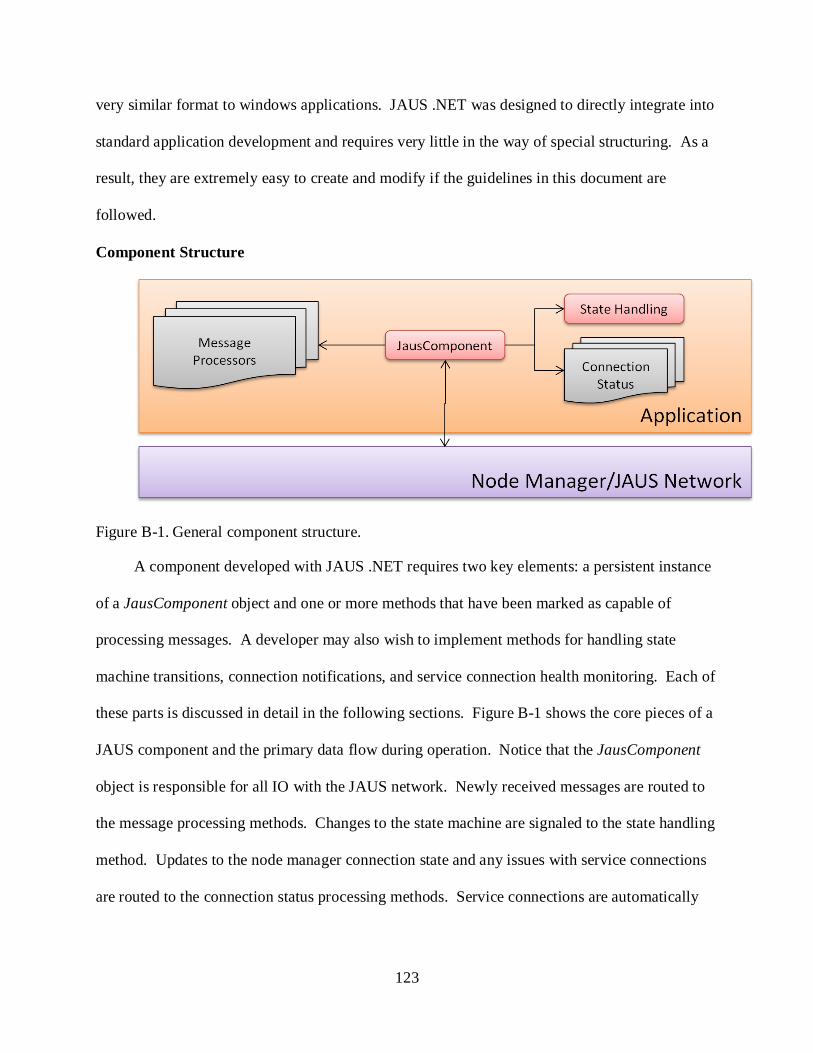
123
very similar format to windows applications. JAUS .NET was designed to directly integrate into
standard application development and requires very little in the way of special structuring. As a
result, they are extremely easy to create and modify if the guidelines in this document are
followed.
Component Structure
Figure B-1. General component structure.
A component developed with JAUS .NET requires two key elements: a persistent instance
of a JausComponent object and one or more methods that have been marked as capable of
processing messages. A developer may also wish to implement methods for handling state
machine transitions, connection notifications, and service connection health monitoring. Each of
these parts is discussed in detail in the following sections. Figure B-1 shows the core pieces of a
JAUS component and the primary data flow during operation. Notice that the JausComponent
object is responsible for all IO with the JAUS network. Newly received messages are routed to
the message processing methods. Changes to the state machine are signaled to the state handling
method. Updates to the node manager connection state and any issues with service connections
are routed to the connection status processing methods. Service connections are automatically

124
managed, created, and monitored by JAUS .NET, only requiring a developer to start the
connection process for inbound services.
JausComponent
At the core of any JAUS .NET application is the JausComponent object. Figure B-2
shows the major elements of the JausComponent and its base class. It handles everything from
network IO to message routing and state transitions. It is necessary for an application to have
one and only one persistent instance of a JausComponent. This object is self-regulating, so a
developer only needs to initialize it once. After this, all regulation is performed with the state
machine. The component is already designed to perform certain tasks in particular states,
meaning the end application simply needs to force a state transition to cause the appropriate
behavior. The structure and handling of the state machine are discussed later.
Figure B-2. JausComponent inheritance and primary features.
JausComponent and the base NMI class define a number of methods, properties, and
events that provide access to critical features. The most important methods are Send, SetState,
and CreateInboundServiceConnection. Send is used to send JAUS messages over the network

125
while SetState allows the developer to manually transition the state machine. The other class
members give access to the message handlers, service connection manager, general component
information, and finally the events that notify of connection and state changes. Each of these
elements will be discussed in detail in later sections.
Initialization of the JausComponent requires several steps. First, the object must be
allocated with the desired component ID and the UDP ports for JAUS and interface
communications. It is important to note that since JAUS .NET was designed to work with the
OpenJAUS node manager, it actually uses two types of messages. JAUS messages are those
defined in the JAUS RA and are common to all JAUS components, regardless of build.
However, interface messages are specific constructs defined by OpenJAUS to address the need
for basic interactions with the node manager such as check-in processes.
The second step to initialization is to attach the message processors to the component.
This allows newly received message to be passed to the appropriate sections of the application.
All messages are routed in the application via MessageHandler objects. These are discussed in
detail in the RCF and the derived handlers used in JAUS .NET are described in the next section.
Also note that as described in the RCF documentation, it is possible to dynamically attach
additional message processors while the component is running. While this technique will rarely
be used, there exist some situations where it can be quite convenient.
The third step is to attach the methods for state and connection processing. While optional,
it is generally recommended to attach these methods as they can provide better control of and
information about application behavior. The most important method to define is for state
handling as most of the behavioral transitions will occur when the state changes.

126
The final step is to define the service information for the component, composed of the lists
of supported input and output messages. The internal service connection manager uses this
information to determine what services can be handled and requires at least proper definition of
the outbound services. The manager is discussed in detail in a later section.
Once the JausComponent has been initialized, the application is ready for operation.
Starting the component is as simple as forcing the state machine into STARTUP. Then the
component will automatically check into the node manager, start the heartbeat, and begin routing
messages to the attached processors. The next section discusses the operation and use of the
message handlers.
Message handlers
JAUS .NET defines two message handlers that are responsible for all message routing and
communications in the application: the JausMessageHandler and the InterfaceMessageHandler.
They are accessed via the JMH and IMH properties respectively of the JausComponent. Since
both are derived from the RCF defined MessageHandler class, they provide methods for
attaching message processing objects and specifying additional message libraries.
The JausComponent automatically adds the core messages for the JAUS RA, but there
may be situations where experimental messages are used. Message libraries can be added to the
handlers via two methods, AddMessageAssembly and AddMessageModule. The key difference is
in the definition of .NET assemblies and modules. An assembly in .NET is a collection of
compiled modules that are logically connected. It can consist of multiple libraries and
executables, but is often only one file. A module is a single library file that is part of an
assembly. The ability to add a single module as a source of message definitions is available in
case a developer wishes to add a single library file rather than all files associated with an
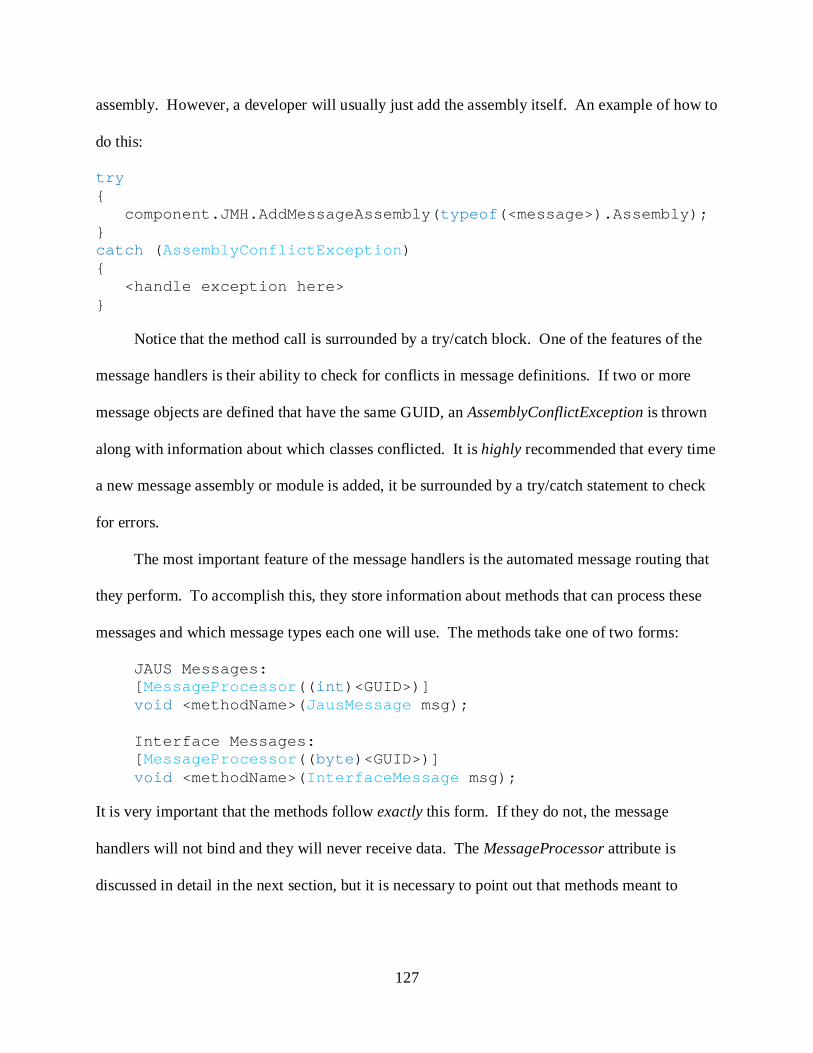
127
assembly. However, a developer will usually just add the assembly itself. An example of how to
do this:
try { component.JMH.AddMessageAssembly(typeof(<message>).Assembly); } catch (AssemblyConflictException) { <handle exception here> }
Notice that the method call is surrounded by a try/catch block. One of the features of the
message handlers is their ability to check for conflicts in message definitions. If two or more
message objects are defined that have the same GUID, an AssemblyConflictException is thrown
along with information about which classes conflicted. It is highly recommended that every time
a new message assembly or module is added, it be surrounded by a try/catch statement to check
for errors.
The most important feature of the message handlers is the automated message routing that
they perform. To accomplish this, they store information about methods that can process these
messages and which message types each one will use. The methods take one of two forms:
JAUS Messages: [MessageProcessor((int)<GUID>)] void <methodName>(JausMessage msg); Interface Messages: [MessageProcessor((byte)<GUID>)] void <methodName>(InterfaceMessage msg);
It is very important that the methods follow exactly this form. If they do not, the message
handlers will not bind and they will never receive data. The MessageProcessor attribute is
discussed in detail in the next section, but it is necessary to point out that methods meant to

128
process JAUS messages must initialize the attribute with an integer while interface message
methods always use a byte GUID.
Attaching these processing methods can be accomplished in two ways using the
AddMessageProcessor method. Either the methods will be tagged pre-compile with the
MessageProcessor attribute, or they will be dynamically added to the message handler along
with GUID info. The two approaches look like:
Processing class: class ExampleClass { // This method will be added automatically. [MessageProcessor((int)<GUID>)] void Predefined(JausMessage msg) { ... } // This method will be added dynamically. void Dynamic(JausMessage msg) { ... } } Adding the methods: void SomeFunction(JausComponent component, ExampleClass example) { // Adds any methods that were pre-tagged to the message // handler. Predefined gets added here. component.JMH.AddMessageProcessor(example); // Adds a single method to the handler and associates the // message GUID with it. The method ‘Dynamic’ from // ExampleClass gets added here. component.JMH.AddMessageProcessor( new JausMessageProcessorCallback(example.Dynamic), (int)<GUID>); }
The second approach of dynamically adding a non-tagged method will rarely be used. A
developer will instead mark all of the processing methods with the MessageProcessor attribute
and then simply pass an instance of the encapsulating class to the AddMessageProcessor method.
The latter approach is only used in situations where the message type is unknown until runtime

129
or to add static methods. The next section discusses the MessageProcessor attribute in greater
detail along with the structure of a JAUS message in this framework.
Message processors and message structure
As discussed previously, the MessageProcessor attribute is used to tag methods as capable
of receiving a message object and the specific message type or types desired. The attribute can
be applied multiple times to a single method with each specifying a different message type. Its
inheritance flag has also been set to true, allowing the message processing methods from a class
to be retrieved from a derived class. An example of this is the JausComponent object which
itself inherits from the NMI class. The NMI defines the actual message processors while the
JausComponent class simply adds some specific functionality to simplify use of the NMI.
JAUS message structure: All JAUS messages passed to processing methods follow the
same format; the JausMessage object consists of a header and a contents object as shown in
Figure B-3. The contents can be any data type and must be cast by the receiving method.
Figure B-3. JausMessage structure.
The JausHeader class contains all of the elements of the header specified in the JAUS RA.
The main properties that a developer will use are Source and Destination that specify the JAUS
addresses used for message routing. The destination address must be manually set on outbound

130
messages for standard communications. However, the service connection manager will
automatically set the destination address for any outbound connections. The JausAddress class
stores the information for subsystem, node, component, and instance IDs. Several constructors
are available that allow creation using numbers as well as strings.
Interface message structure: The main interaction that a JAUS component will have with
interface messages is monitoring specific events, such as an update to the component’s address.
Interface messages are similar in form to their JAUS counterparts. They consist of a one byte
header and a contents object that needs to be cast by the receiving method. It is highly
recommended that a developer never send interface messages as these have very specific
functionality. At most a handful of methods may be created to listen for particular messages to
update the application display.
State machine
A number of states are defined under the EComponentState enumeration as shown in
Figure B-4. State changes are signaled to the application via the OnStateChanged event and
indicate which state to which the machine has transitioned. The code for the current state and the
previous state can be accessed directly through the CurrentState and PreviousState properties of
the NMI. An application can force a state transition by calling the SetState method and
specifying the enumeration for the desired end state. It is important to note that the current state
machine implementation does not impose guard conditions on the transitions as these are not
specified in the JAUS RA. Therefore, if certain conditions must be met beforehand, it is up to
the developer to impose these restrictions in his code.
Three states are automatically handled by the JausComponent and have very particular
meanings. STARTUP causes the component object to reinitialize itself, begin the check-in
process to the node manager, and start all of its internal threads and timers. Once check-in has

131
completed, the component automatically transitions to INITIALIZE, which performs timer
cleanup. SHUTDOWN causes the component to perform a check-out and shut down all internal
threads and timers. Proper procedure for component startup is to perform a SetState to
STARTUP and wait for it to transition to INITIALIZE. Then the application can operate
normally. When the application is to be shutdown or restarted, it is vital to perform a SetState to
SHUTDOWN to ensure that the threading is cleaned up properly and that the component logs
out of the node manager. If this is not done, either the application will not shut down due to
orphaned threads or the component will be unable to log in due to ID and port conflicts with its
previous instance.
Figure B-4. States and state enumerations.
Service connections
Since JAUS is a service oriented architecture, a management class has been built into the
JausComponent. It is responsible for creating, monitoring, updating, and destroying service
connections. Most of the process is automated and requires very little input from the end
application. The service connection manager (SCM) is accessed through the SCM property of
the JausComponent and provides three events to signal connection status. The events

132
OnNewServiceConnection and OnDestroyedServiceConnection can be used to signal the
application when both inbound and outbound connections are created or terminated. The
OnBadConnection event allows a developer to set one or more methods that will be signaled if a
service connection is having problems such as timing out. The service connection manager itself
does not fire this callback but rather internal objects used for monitoring perform this function.
Please refer to the compiled help file for JAUS .NET for more details on the use of these
callbacks.
The service connection manager automatically sends update messages to each of the
outbound addresses from an internal hashtable of messages. These are identified by command
code and can be added and accessed by the AddOutboundMessage and GetOutboundMessage
methods respectively. It is important to note that while the SCM sends messages according to
the subscribers’ schedules, it is remains the responsibility of the developer to make sure that
these messages are current and are refreshed at the proper rate.
Major Namespaces
JAUS .NET and the RCF are comprised of numerous namespaces to separate functionality.
The primary namespaces that will be used in every application are discussed in this section.
Please note that this is by no means a complete overview of the namespaces and available
constructs, but rather a quick summary of the most commonly used features and objects. To
access these namespaces, it is necessary to add references to the following three libraries:
GenericSerialization, ComUtilities, and JausLib. Another library named CimarLib may also be
referenced for certain experimental messages specific to the CIMAR lab.

133
Jaus.Nmi
The Jaus.Nmi namespace contains the definitions for JausComponent and
EComponentState. It is highly recommended that every component application include this
namespace in the using statements.
Jaus.Nmi.Services.
The Jaus.Nmi.Services namespace contains definitions for a service type enumeration and
two objects that can be used to define supported services and messages. It may be desirable to
reference this namespace in the file that defines component initialization.
Jaus.Messages
The Jaus.Messages namespace contains the definitions for JausMessage, JausHeader,
JausAddress, JausPresenceVector, and EJausMessageType, all of which are heavily used.
Numerous sub namespaces are also present that provide specific message definitions. To handle
scaled representations as per the JAUS RA, look at Jaus.Messages.Utils.
Jaus.InterfaceMessages
The Jaus.InterfaceMessages namespace contains the definition for InterfaceMessage as
well as all of the actual interface messages. This namespace is only needed if the application
needs access to interface messaging.
Rcf.Utilities.Threading
While the RCF defines many namespaces and tools, the only namespace that will regularly
be directly used by JAUS components is Rcf.Utilities.Threading. It contains the definition for
the MessageProcessor attribute used to indicate processing methods. It also contains an abstract
class called ThreadControl that greatly simplifies the creation of a threaded object. This may be
extremely useful to certain developers.

134
Example Components
This section presents several examples of how to create a JAUS component application
using the tools previously described. These include a simple forms application, a console
application that subscribes to a service provider, and finally a service provider to complement the
previous two examples. The explanations here do not present all aspects of application
development, but rather focus on the key areas needed to integrate the JausComponent.
However, the source code and projects as well as compiled help files for each example have been
provided along with this document. They are thoroughly commented and well organized to
make them easy to follow.
SimpleComponent
The most common type of JAUS component that will be created with .NET is a Windows
Forms application that has a persistent main form and possibly several children. Typically the
application behavior will be defined in the main form as a number of processing methods. The
form itself will contain, as a member, the JausComponent object and will attach itself to this
object during initialization. Message processing methods as well as the various event and status
update methods will all be defined in form. In this example, the process of developing a very
simple form component will be discussed.
Figure B-5 shows the main form design and layout. The application has four buttons for
basic actions and several labels to display information as it is updated. The x,x,x label will be
used to display data from the service connection while the status strip at the bottom will show
state and address information. The Startup and Check Out buttons are used to check-in and
check-out of the network. The Connect and Disconnect buttons are used to establish and
terminate an inbound service connection. These will be discussed in detail later.
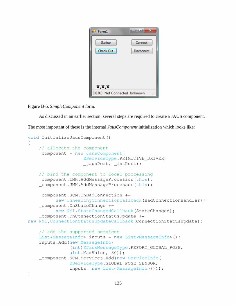
135
Figure B-5. SimpleComponent form.
As discussed in an earlier section, several steps are required to create a JAUS component.
The most important of these is the internal JausComponent initialization which looks like:
void InitializeJausComponent() { // allocate the component _component = new JausComponent(
EServiceType.PRIMITIVE_DRIVER, _jausPort, _intPort);
// bind the component to local processing _component.IMH.AddMessageProcessor(this); _component.JMH.AddMessageProcessor(this); _component.SCM.OnBadConnection +=
new UnhealthyConnectionCallback(BadConnectionHandler); _component.OnStateChange +=
new NMI.StateChangedCallback(StateChanged); _component.OnConnectionStatusUpdate += new NMI.ConnectionStatusUpdateCallback(ConnectionStatusUpdate); // add the supported services List<MessageInfo> inputs = new List<MessageInfo>(); inputs.Add(new MessageInfo(
(int)EJausMessageType.REPORT_GLOBAL_POSE, uint.MaxValue, 30));
_component.SCM.Services.Add(new ServiceInfo( EServiceType.GLOBAL_POSE_SENSOR, inputs, new List<MessageInfo>()));
}

136
Several things are happening in this method. First, the internal component is allocated followed
by attachment of the form to the message handlers. The AddMessageProcessor methods accept
the form object, identified by the this keyword, and extract all of the methods that have
MessageProcessor tags on them. The only reason both message handlers are used is to simplify
display of the component address once it has been assigned. It is not necessary to attach the
form to the interface message handler at all if the only interest is in reception of JAUS messages.
Next, specific events are attached to handle state changes and other notifications. The methods
in this example only perform updates to the form display when they are signaled, but more
complex implementations are perfectly reasonable.
The final step in the initialization method is the addition of supported services information
to the manager. Individual supported messages are identified with MessageInfo objects and lists
of these form the input and output sets. The lists are further encapsulated in a ServiceInfo object
that attaches a GUID to the entire service. This complexity is due to the design in the JAUS RA
and cannot be avoided. In this example, the component is only meant to act as a subscriber, so a
list of input messages is populated while an empty list is created for the output set.
In this example, only two message processing methods are defined. One handles the
interface message assigning the component address while the other updates the form with the
latest global pose message data. These methods are:
[MessageProcessor((byte)EInterfaceMessageType.REPORT_ADDRESS)] void AddressAssigned(InterfaceMessage msg) { ReportAddress addressMsg = msg.Data as ReportAddress; if (addressMsg != null) _addressLabel.Text = addressMsg.Address.ToString(); } [MessageProcessor((int)EJausMessageType.REPORT_GLOBAL_POSE)] void GPoseUpdate(JausMessage msg) {

137
ReportGlobalPose gpose = msg.Contents as ReportGlobalPose; UpdateLabel(_gposeLabel, gpose.Latitude.ToString() + ", "
+ gpose.Longitude.ToString() + ", " + gpose.Elevation.ToString());
}
Notice the different GUIDs used for the two types of processors. The method receiving interface
messages uses a byte GUID whereas the JAUS message processor uses integers as discussed
previously. Since these methods are part of the form object, when it is passed to the
AddMessageProcessor method, they are identified and bound to the message handlers.
The final set of methods to inspect are those attached to the buttons on the form. The
Startup button begins the check-in process by pushing the component into STARTUP using:
_component.SetState(EComponentState.STARTUP);
Remember that the JausComponent state processing automates the process, so this is the
recommended approach for starting the component. The Check Out button simply pushes the
component into SHUTDOWN to stop the component and perform cleanup:
_component.SetState(EComponentState.SHUTDOWN);
The Connect and Disconnect buttons are responsible for creating and terminating an
inbound service connection to a global pose provider. Creation of the connection is relatively
simple, though it does require a fairly long line of code:
JausAddress searchAddress = new JausAddress(0, 0, (int)EServiceType.GLOBAL_POSE_SENSOR, 0); _component.SCM.CreateInboundServiceConnection(searchAddress, (int)EJausMessageType.REPORT_GLOBAL_POSE, _gposeSupport, 2);
The call to CreateInboundServiceConnection requires a JausAddress that identifies the
component to search for in addition to the desired message type, fields, and update rate. The
requirement for a partially defined address is a limitation of the current OpenJAUS node
manager and cannot be avoided. Later builds may address this issue.

138
While creation of a service connection can be somewhat confusing, fortunately termination
is extremely simple. The SCM contains several methods for connection management and the
easiest way to terminate the connections is:
_component.SCM.TerminateAllInboundConnections();
This method systematically closes each service connection for the user, avoiding potential
cleanup issues. It is also possible to manage each connection individually, but the easiest and
safest approach is to perform a general shutdown. Refer to the help file for information on some
of the other management methods.
This simple component example shows the basics of creating a JAUS component using the
tools in JAUS .NET. The important parts to understand are component initialization and
attachment and definition of message processing methods. The basic state handling covers all of
the critical functions, so once the internal component object has been initialized, the application
is ready for operation. The next section discusses another component that performs similar
functions to this example with a very different interface.
ConsoleComponent
While many applications in .NET are Windows Forms, creating a console component is
essentially the same process. All applications consist of a Program class that contains a static
Main method that acts as the entry point. In the case of Windows Forms, the Main method will
create an instance of the main form and display it to the user. This form typically contains much
of the functionality and UI elements needed for operation and in the case of JAUS components
will often encapsulate the JausComponent object and any processing methods. For a console
application a similar approach is used, except instead of creating a form that defines the
behavior, a more general class will be created. It will still contain the message processing
elements previously discussed, only without the UI elements.

139
Figure B-6. ConsoleComponent user interface.
A processing class called ReceiverClass performs most of the functions of the main form
from the SimpleComponent example. It contains the JausComponent, message processing
methods, and event handlers. The JausComponent is initialized in the same way as the
SimpleComponent. The only major difference between the two applications is the user interface.
The Main method of the Program class allocates a new instance of the receiver class then
begins the loop to process user inputs; the interface is shown in Figure B-6. Depending on the
user selection, the main method performs one of several tasks. If login is selected, then the
component is pushed to STARTUP while logout and quit cause a transition to SHUTDOWN.
The options connect and disconnect call methods in ReceiverClass that create and terminate
service connections just like the SimpleComponent. The rest of the methods in ReceiverClass
are used to update the display with connection information.
GPoseProvider
The previous two examples dealt with how to create components that can subscribe to
services. However, it is highly likely that actual component will also need to act as service

140
providers. This example shows how to create a simple application to which the previous
components can subscribe. Figure B-7 shows the form displayed when the application is run.
Notice that user interaction is not possible. Instead, this component is fully automated, from
check-in to updating of message information, to cleanup and shutdown.
Figure B-7. GPoseProvider main form.
As with SimpleComponent, the main form for GPoseProvider contains the necessary
JausComponent and performs initialization. The two differences in initialization are that the
supported service has a populated outbound list rather than an inbound list and that an outbound
message is added to the SCM:
_component.SCM.OutboundMessage = new JausMessage(new JausHeader(), new ReportGlobalPose());
_component.SCM.AddOutboundMessage( (int)EJausMessageType.REPORT_GLOBAL_POSE, new ReportGlobalPose());
List<MessageInfo> outboundMessages = new List<MessageInfo>(); outboundMessages.Add(
new MessageInfo((int)EJausMessageType.REPORT_GLOBAL_POSE, new ReportGlobalPose().PresenceVector, 30));
ServiceInfo info = new ServiceInfo( EServiceType.GLOBAL_POSE_SENSOR, new List<MessageInfo>(), outboundMessages);
_component.SCM.RegisterSupportedServices(info);
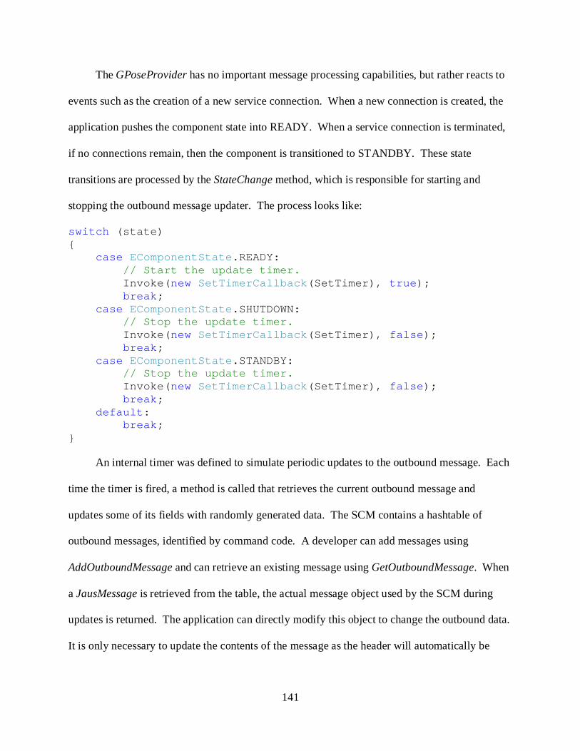
141
The GPoseProvider has no important message processing capabilities, but rather reacts to
events such as the creation of a new service connection. When a new connection is created, the
application pushes the component state into READY. When a service connection is terminated,
if no connections remain, then the component is transitioned to STANDBY. These state
transitions are processed by the StateChange method, which is responsible for starting and
stopping the outbound message updater. The process looks like:
switch (state) { case EComponentState.READY: // Start the update timer. Invoke(new SetTimerCallback(SetTimer), true); break; case EComponentState.SHUTDOWN: // Stop the update timer. Invoke(new SetTimerCallback(SetTimer), false); break; case EComponentState.STANDBY: // Stop the update timer. Invoke(new SetTimerCallback(SetTimer), false); break; default: break; }
An internal timer was defined to simulate periodic updates to the outbound message. Each
time the timer is fired, a method is called that retrieves the current outbound message and
updates some of its fields with randomly generated data. The SCM contains a hashtable of
outbound messages, identified by command code. A developer can add messages using
AddOutboundMessage and can retrieve an existing message using GetOutboundMessage. When
a JausMessage is retrieved from the table, the actual message object used by the SCM during
updates is returned. The application can directly modify this object to change the outbound data.
It is only necessary to update the contents of the message as the header will automatically be

142
populated during send operations. However, if particular flags need to be changed, such as
ACK/NAK, these can be modified at any time. The update method is:
JausMessage outboundMsg = _component.SCM.GetOutboundMessage(
(int)EJausMessageType.REPORT_GLOBAL_POSE); if (outboundMsg != null) { ReportGlobalPose gPose =
outboundMsg.Contents as ReportGlobalPose; lock (gPose) { gPose.Latitude = <generate random value> gPose.Longitude = <generate random value> gPose.Elevation = <generate random value> } }
Startup and shutdown processes have been automated as well. The MainForm_Load and
MainForm_Closing methods force the component into STARTUP and SHUTDOWN
respectively. This means that when the application runs, once the form displays, the component
attempts to perform a check-in and when the form is closed, the component does a check-out and
cleanup to free all resources and threads. Since the entire application is event-driven, it simply
needs to be run to act as a service provider. External components cause the changes in its
behavior through standard messaging.

143
Custom messages
While most components can be fully implemented using the tools provided in JAUS .NET,
there may be situations in which custom experimental messages are required. This section
discusses some of the steps needed for custom message creation. However, it does not provide a
full explanation of message structure and how to properly use all of the tools. There is simply
too much information to effectively discuss in a brief help document such as this. A full
explanation of how to develop message object is presented in the main dissertation on the RCF
and the JAUS .NET reference implementation. The chapter on JAUS .NET provides several
very detailed examples of how to create new message types.
For an object to be usable as the contents of a JausMessage, two features must be included.
First, the data type must be marked with an attribute that provides its associated command code.
This is necessary for the JausMessageHandler to properly determine which data type to use
when processing the message during communications. Second, the data type has to be marked
with serialization attributes that identify the parts that must be processed during conversion by
the message handler and network interface.
JausContents Attribute
The JausContents attribute is used to attach the command code for the data type. Its
constructor accepts a single integer that represents the command code. Proper usage is:
[JausContents((int)<commandCode>)] class <typeName> { ... }
At runtime, the command code will be checked against those of other known data types and any
conflicts will raise an exception that identify the offending data types and assemblies. It is up to
the developer to ensure that a non-conflicting command code is selected. Also note that only one
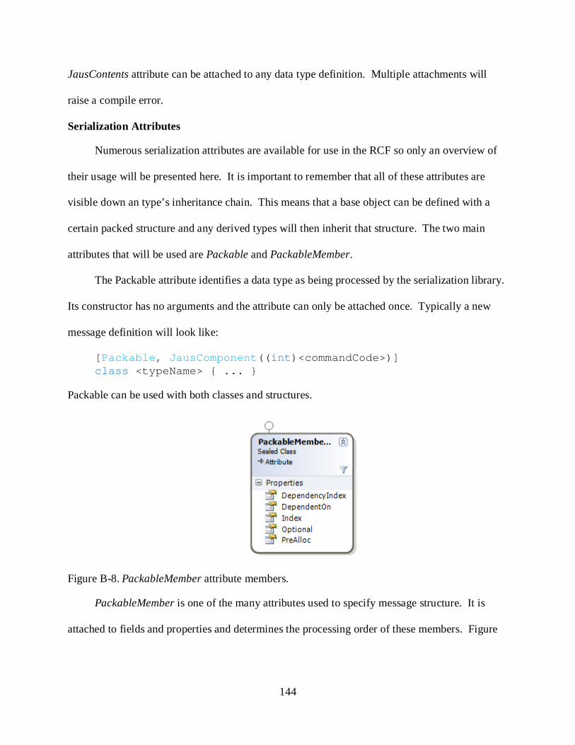
144
JausContents attribute can be attached to any data type definition. Multiple attachments will
raise a compile error.
Serialization Attributes
Numerous serialization attributes are available for use in the RCF so only an overview of
their usage will be presented here. It is important to remember that all of these attributes are
visible down an type’s inheritance chain. This means that a base object can be defined with a
certain packed structure and any derived types will then inherit that structure. The two main
attributes that will be used are Packable and PackableMember.
The Packable attribute identifies a data type as being processed by the serialization library.
Its constructor has no arguments and the attribute can only be attached once. Typically a new
message definition will look like:
[Packable, JausComponent((int)<commandCode>)] class <typeName> { ... }
Packable can be used with both classes and structures.
Figure B-8. PackableMember attribute members.
PackableMember is one of the many attributes used to specify message structure. It is
attached to fields and properties and determines the processing order of these members. Figure

145
B-8 shows the properties available for the attribute. The most commonly used property is Index;
members with a smaller index are processed before those with a larger index.
A large number of messages can be defined using nothing more than the PackableMember
attribute and index property. For example, a simple message might contain two fields:
[Packable, JausContents(0xFF02)] public class ExampleMessage { [PackableMember(Index=0)] int firstValue; [PackableMember(Index=1)] double secondValue; }
The command code for the message above is 0xFF02 and the two fields would be processed in
the order: firstValue, secondValue. Reversing the indices would reverse the order of processing.
More complex message structures require the use of the other properties of
PackableMember as well as the attributes DependencySpecifier, OnPacking, OnMidPacking,
OnPacked, OnUnpacking, OnMidUnpacking, and OnUnpacked. These latter seven attributes are
used to mark specialized processing methods that may be required for certain message structures.
It is imperative that the full explanation of how to design and implement message objects be read
before any attempt is made to use these tools. While improper use will not break the application,
it is almost certain that unexpected results will be produced without a full understanding of the
serialization process.

146
LIST OF REFERENCES
[Abu-Ghazaleh et al. 2004] N. Abu-Ghazaleh, M.J. Lewis, M. Govindaraju: “Differential Serialization for Optimized SOAP Performance” High performance Distributed Computing, 2004. Proceedings. 13th IEEE International Symposium on, 4-6 June 2004 Page(s):55 – 64
[Abu-Ghazaleh et al. 2005] N. Abu-Ghazaleh, M.J. Lewis: “Differential Deserialization for Optimized SOAP Performance” Supercomputing, 2005. Proceedings of the ACM/IEEE SC 2005 Conference, 12-18 Nov. 2005 Page(s):21 - 21
[Baehni et al. 2003] S. Baehni, P. Eugster, R. Guerraoui, P. Altherr: “Pragmatic Type Interoperability” Distributed Computing Systems, 2003. Proceedings. 23rd International Conference on, 19-22 May 2003 Page(s):404 - 411
[Barron 2001] T. Barron: “Multiplayer Game Programming”, Prima Publishing, CA 2001
[Brose et al. 1997] G. Brose, L. Lohr, A. Spiegel: “Java Resists Transparent Distribution” Object Magazine, December 1997
[Calvert/ Donahoo 2001] K. Calvert, M. Donahoo: “TCP/IP Sockets in C Practical Guide for Programmers”, Morgan Kaufmann Publishers, CA 2001
[Cao et al. 1997] Y. Cao, A. Fukunaga, A. Kahng: “Cooperative Mobile Robotics: Antecedents and Directions” Autonomous Robots, 4, 1-23 1997
[Davis/Parashar 2002] D. Davis, M.P. Parashar: “Latency Performance of SOAP Implementations” Cluster Computing and the Grid, 2002. 2nd IEEE/ACM International Symposium on, 21-24 May 2002 Page(s):407 – 407
[Davis/Zhang 2002] A. Davis, D. Zhang: “A Comparative Study of DCOM and SOAP” Multimedia Software Engineering, 2002. Proceedings. Fourth International Symposium on, 11-13 Dec. 2002 Page(s):48 – 55
[Fallah et al. 2007] S. Fallah, E. Moghaddam, A. Parsa: “An Event-Driven Pattern for Asynchronous Invocation in Distributed Systems” IJCSNS International Journal of Computer Science and Network Security, Vol.7 No.4, April 2007
[Flanagan 2005] D. Flanagan: “Java in a Nutshell, Fifth Edition”, O’Reilly Media, Inc., CA 2005
[Hong et al. 2006] S. Hong, J. Lee, H. Eom, G. Jeon: “The Robot Software Communications Architecture (RSCA): Embedded Middleware for Networked Service Robots” Parallel and Distributed Processing Symposium, 2006. IPDPS 2006. 20th International, 25-29 April 2006 Page(s):8 pp.
[Jackson 2007] J. Jackson: “Microsoft Robotics Studio: A Technical Introduction” Robotics & Automation Magazine, IEEE Volume 14, Issue 4, Dec. 2007 Page(s):82 - 87

147
[Jie et al. 2002] W. Jie, W. Cai, S. Turner: “POEMS: A Parallel Object-oriented Environment for Multi-computer Systems” The Computer Journal, Vol. 45, No. 5, 2002
[Johns/Taylor 2008] K. Johns, T. Taylor: “Professional Microsoft Robotics Developer Studio”, Wiley Publishing, Inc., ID 2008
[JWG 2007] JAUS: “JAUS Reference Architecture, version 3.3” JAUS Working Group
[Kim et al. 2007] S. Kim, S. Kim, J. Sung, T. Lopez: “Template based High Performance ALE-TSOAP Message Communication” Software Engineering Research, Management & Applications, 2007. SERA 2007. 5th ACIS International Conference on, 20-22 Aug. 2007 Page(s):534 – 544
[Kramer 1994] J. Kramer: “Distributed Software Engineering” Software Engineering, 1994. Proceedings. ICSE-16., 16th International Conference on, 16-21 May 1994 Page(s):253 - 263
[Micucci et al. 2004] D. Micucci, S. Ruocco, F. Tisato: “Time Sensitive Architectures: a Reflective Approach” Object-Oriented Real-Time Distributed Computing, 2004. Proceedings. Seventh IEEE International Symposium on, 14-14 May 2004 Page(s):189 – 196
[Newkirk/Voronstov 2002] J. Newkirk, A.A. Vorontsov: “How .NET’s Custom Attributes Affect Custom Design” Software, IEEE Volume 19, Issue 5, Sept.-Oct. 2002 Page(s):18 - 20
[Niemeyer/Knudsen 2005] P. Niemeyer, P. Knudsen: “Learning Java, Third Edition”, O’Reilly Media, Inc., CA 2005
[Oprychal/Prakash 1999] L. Opyrchal, A. Prakash: “Efficient object serialization in Java” Electronic Commerce and Web-based Applications/Middleware, 1999. Proceedings. 19th IEEE International Conference on Distributed Computing Systems Workshops on, 31 May-4 June 1999 Page(s):96 - 101
[Pautet/Tardieu 2000] L. Pautet, S. Tardieu: “GLADE: a Framework for Building Large Object-Oriented Real-time Distributed Systems” Object-Oriented Real-Time Distributed Computing, 2000. (ISORC 2000) Proceedings. Third IEEE International Symposium on, 15-17 March 2000 Page(s):244 - 251
[Payrits et al. 2006] S. Payrits, P. Dornback, I. Zolyomi: “Metadata-Based XML Serialization for Embedded C++” Web Services, 2006. ICWS '06. International Conference on, Sept. 2006 Page(s):347 - 356
[Platt 2003] D. Platt: “Introducing Microsoft .NET”, Third Edition, Microsoft Press, WA 2003
[Purtilo 1994] J. Purtilo: “The Polylith Software Bus” ACM Transactions on Programming Languages and Systems, Vol. 16, 1994, Page(s):151 – 174
[Schmelzer 2002] R. Schmelzer: “XML and Web Services Unleashed”, Sams Publishing 2002

148
[Schmidt 1992] D. Schmidt: “IPC SAP C++ Wrappers for Efficient, Portable, and Flexible Network Programming” C++ Report, November/December 1992
[Schwarzkopf et al. 2008] R. Schwarzkopf, M. Mathes, S. Heinzl, B. Freisleben, H. Dohmann: “Java RMI versus .NET Remoting Architectural Comparison and Performance Evaluation” Networking, 2008. ICN 2008. Seventh International Conference on, 13-18 April 2008 Page(s):398 – 407
[Smeda et al. 2005] A. Smeda, T. Khammaci, M. Oussalah: “Meta Architecting: Toward a New Generation of Architecture Description Languages” Journal of Computer Science 1 (4): 454-460, 2005
[Touchton et al. 2006] B. Touchton, T. Galluzzo, D. Kent, C. Crane: “Perception Planning Architecture for Autonomous Ground Vehicles” Computer, Volume 39, Issue 12, Dec. 2006 Page(s):40 - 47
[Troelson 2007] A. Troelson: “Pro C# 2008 and the .NET 3.5 Platform, Fourth Edition”, Springer-Verlag New York, Inc., NY 2007

149
BIOGRAPHICAL SKETCH
Jean-Francois A. Kamath holds a BS in mechanical engineering (2002) and a Masters in
mechanical engineering (2005) from the University of Florida. He completed his doctoral degree
from the University of Florida at the Center for Intelligent Machines and Robotics (2009). He
intends to continue his career in applied research and advanced systems development.
Related Documents


