212 Estonian Journal of Engineering, 2013, 19, 3, 212–238 doi: 10.3176/eng.2013.3.04 Refined models and control solutions for mechatronics design of mobile robotic platforms Farhan A. Salem a,b a Mechatronics program, Department of Mechanical Engineering, Faculty of Engineering, Taif University, 888 Taif, Saudi Arabia; [email protected] b Alpha Center for Engineering Studies and Technology Researches, Amman, Jordan Received 13 February 2013, in revised form 23 May 2013 Abstract. This paper presents new refined mathematical, Simulink and function block models for mobile robots, and some considerations regarding mechatronics design and control solutions. The presented models are mainly intended to be used to help in facing the two top challenges in developing mechatronic mobile robotic systems: firstly, early identifying system level problems and ensuring that all design requirements are met, and secondly, to be used for research purposes and application in educational process. The presented models, blocks and designs were created and verified using MATLAB/Simulink software. Testing models for achieving desired design specifica- tions shows the applicability and accuracy of the design. The results also show that PID, PI and PI with deadbeat response are applicable for achieving desired smooth speed of a given mobile robot with acceptable stability and fastness of response. Key words: mechatronics system, mobile platform, motion control, control strategy, function block. 1. INTRODUCTION Mobile robot is a platform with a large mobility within its environment (air, land, underwater), it is not fixed to one physical location. Mobile robots have potential application in industrial and domestic applications; in exploration, industry, military, security and entertainment like special needs robots, fire and security robots, office robots, etc. Accurate designing and control of a mobile robot is not a simple task, in that operation of the mobile robot is essentially time-variant, where the operation parameters of the mobile robot, environment and the road conditions are always varying. Therefore, the mobile robot as a whole, as well as the controller should be designed to make the system robust and adaptive, improving the system on both dynamic and steady state per-

Welcome message from author
This document is posted to help you gain knowledge. Please leave a comment to let me know what you think about it! Share it to your friends and learn new things together.
Transcript

212
Estonian Journal of Engineering, 2013, 19, 3, 212–238 doi: 10.3176/eng.2013.3.04
Refined models and control solutions for mechatronics design of mobile robotic platforms
Farhan A. Salema,b
a Mechatronics program, Department of Mechanical Engineering, Faculty of Engineering, Taif
University, 888 Taif, Saudi Arabia; [email protected] b Alpha Center for Engineering Studies and Technology Researches, Amman, Jordan Received 13 February 2013, in revised form 23 May 2013 Abstract. This paper presents new refined mathematical, Simulink and function block models for mobile robots, and some considerations regarding mechatronics design and control solutions. The presented models are mainly intended to be used to help in facing the two top challenges in developing mechatronic mobile robotic systems: firstly, early identifying system level problems and ensuring that all design requirements are met, and secondly, to be used for research purposes and application in educational process. The presented models, blocks and designs were created and verified using MATLAB/Simulink software. Testing models for achieving desired design specifica-tions shows the applicability and accuracy of the design. The results also show that PID, PI and PI with deadbeat response are applicable for achieving desired smooth speed of a given mobile robot with acceptable stability and fastness of response. Key words: mechatronics system, mobile platform, motion control, control strategy, function block.
1. INTRODUCTION Mobile robot is a platform with a large mobility within its environment (air,
land, underwater), it is not fixed to one physical location. Mobile robots have potential application in industrial and domestic applications; in exploration, industry, military, security and entertainment like special needs robots, fire and security robots, office robots, etc. Accurate designing and control of a mobile robot is not a simple task, in that operation of the mobile robot is essentially time-variant, where the operation parameters of the mobile robot, environment and the road conditions are always varying. Therefore, the mobile robot as a whole, as well as the controller should be designed to make the system robust and adaptive, improving the system on both dynamic and steady state per-

213
formances [1]. Different aspects of mobile robots have been studied. In [1], modelling, simulation and dynamics analysis of an electric motor for mecha-tronics applications are studied and analysed. In [2], mechatronics design of a mobile robot system with overall system modelling, controller selection and design are introduced. In [3], modelling and control of a mobile robot is pro-posed. In [4], computer aided design of a mobile robotic system, controlled remotely by computer, is studied. In [5], design and control issues of a simple two degrees of freedom (2-DOF) positioning device has been investigated. In [6], design and implementation of a PC-based DC motor velocity system, using both special optimal control and PID, has been described. In [7], a control design of a nonholonomic mobile robot with a differential drive is presented. In [8], architecture, characteristics and principle of a mobile immune-robot model are discussed. In [9], software implementation of obstacle detection and for the wheeled mobile robot the avoidance system is introduced.
A general purpose model that can be used to simplify and accelerate overall mechatronics design and evaluation processes of mobile robots and can be used to improve the mobile system on both dynamic and steady state per-formances is desired. This paper proposes such a model; we are going to develop mathematical and Simulink models that can be applied in mechatronics design of a required mobile robotic platform of a specific application, considering all dynamics, with corresponding optimal control strategy for achieving desired system behaviour. The proposed mobile robotic platform can be used to assemble upon it any mobile robot application with corresponding robot chassis.
Mobile robot systems use electric machines (motors) as motion generators, the system takes input voltage as electric motor input, and outputs the rotational speed of electric motor or the motion of the mobile robot. Electric motors are characterized with excellent performance in motion control, due to simple principle of work, and quick instantaneous and accurate torque generation. They are also capable of generating high torque at low speed and can operate efficiently over a great range of speeds. One should also mention the ease of designing and implementing the controller to achieve optimal instantaneous, precise, comfortable, smooth and safe motion control performance with low cost. In most cases they are reversible. DC motor and its features can be tested and analysed both by control system design calculation and by MATLAB software. Also a simple controller of PIC micro, with a corresponding program for the rotation of the DC motor, that is the motion of mobile robotic platform, can be controlled easily and smoothly. The electric machines, most used for mobile robots, are DC motors. Based on this, the mobile robot motion control can be simplified to a DC motor motion control that may or not include a gear system.
A mobile robotic platform can be designed and built using the following components: two in-line with each other DC motors, two H-bridge control circuits, sensors, a microcontroller, embedded on the robot and capable of inputting sensors readings, using readings in its program and making decision of the next movement by controlling the two drive channels. Usually, mobile

214
platforms are supported by two driving rear wheels. The stability is augmented by one or two front caster wheel(s). The two rear wheels are responsible of mov-ing the robot, and are used to turn the robot in any required direction depending on the difference of speed of wheels’ rotation (differential drive style).
2. MODELLING OF THE MOBILE ROBOTIC PLATFORM In this paper, three mathematical and Simulink models for mechatronics
mobile platform design are to be proposed. First, a simplified model; the second model with moderate accuracy and the third refined model, considering all dynamics. Each of the derived models has its advantages, disadvantages and applications. The simplified model can be applied for small mobile robotic applications and prototypes, where the dynamics has small effect on the mobile system performance and can be ignored. For medium and big mobile robotic applications, it is desired to consider major or all the acting dynamics.
The equations of motion for the robot will consider the simple case of the single-degree-of-freedom motion of the mobile platform, moving forward and reverse. A simplified model of mobile platform components and symmetric half of the mobile platform is constructed as shown in Fig. 1 and used to write the equivalent models of every actuator device independently from the other.
(a)
Diff. styleDriveBattery
Control
Ref.
El.MotorVolt.Reg.
Tacho.Sensor
(b) (c)
Gear
DriveBattery
Control
Ref.
El.MotorWheel
Tacho.V.R.
Fig. 1. (a) Mobile platform and circuit, top view; (b) a simple model of half of the mobile platform; (c) gear ratio, pulley or gear train.

215
2.1. Modelling of the electric machine The actuating machines, most used in mechatronics motion control applica-
tions, are DC machines. Therefore the mobile platform motion control can be simplified to a DC motor motion control. In modelling DC motors and in order to obtain a linear model, the hysteresis and the voltage drop across the motor brushes is neglected. The motor input voltage, inV may be applied to the field or armature terminals [10]; in this paper we will consider a PMDC motor as an electric actuator. In [2], a detailed derivation of a mobile robotic platform model, Simulink model and function block with its parameters’ window are introduced. Considering that system dynamics and disturbance torques depend on the platform shape and dimensions, the mechanical DC motor part will have the form given as
,t a load fK i T T T Tα ω= + + + (1)
where tK is the torque constant, ai is the armature current, loadT is load torque, Tα is torque due to acceleration 2 2( d d ),mT J tα θ= Tω is torque due to velocity ( d d ).mT b tω θ= The coulomb friction fT can be found at steady state as
.f t aT K i bω= − (2)
The open loop transfer function of the mobile robot platform is simplified to DC motor open loop transfer function. The PMDC motor open loop transfer function without any load attached, relating the input voltage, ( )inV s to the shaft angular velocity, ( ),sω is given as
( )( )( ) [( )( ) ]
tspeed
in a a m m t b
KsG sV s L s R J s b K Kω= =
+ + +
2 ,[( ) ( ) ( )]
t
a m a m m a a m t b
KL J s R J b L s R b K K
=+ + + +
(3)
where aL is armature inductance, aR is armature resistance, mJ is motor inertia and mb is motor viscous damping. The equivalent mobile robot system open loop transfer function with load and gears attached, in terms of the input voltage,
( )inV s and angular velocity, ( ),robot sω is given as
2( )( ) .
( ) [( ) ( ) ( )]robot t
speedin a equiv a equiv equiv a a equiv t b
s K nG sV s L J s R J b L s R b K K
ω= =
+ + + + (4)
The geometry of the mechanical part determines the moment of inertia. The mobile platform can be considered to be of the cuboid or cubic shape, with the inertia calculated as shown below, where the total equivalent inertia, ,equivJ and total equivalent damping, ,equivb at the armature of the motor with gears attaches, are expressed as
216
2 21 1
2 2
232 1
2
,
( ) .12
equiv m load equiv m load
load equiv motor gear wheel
N Nb b b J J JN N
NbhJ J J J J mrN
= + ⇔ = +
= ⇔ = + + +
(5)
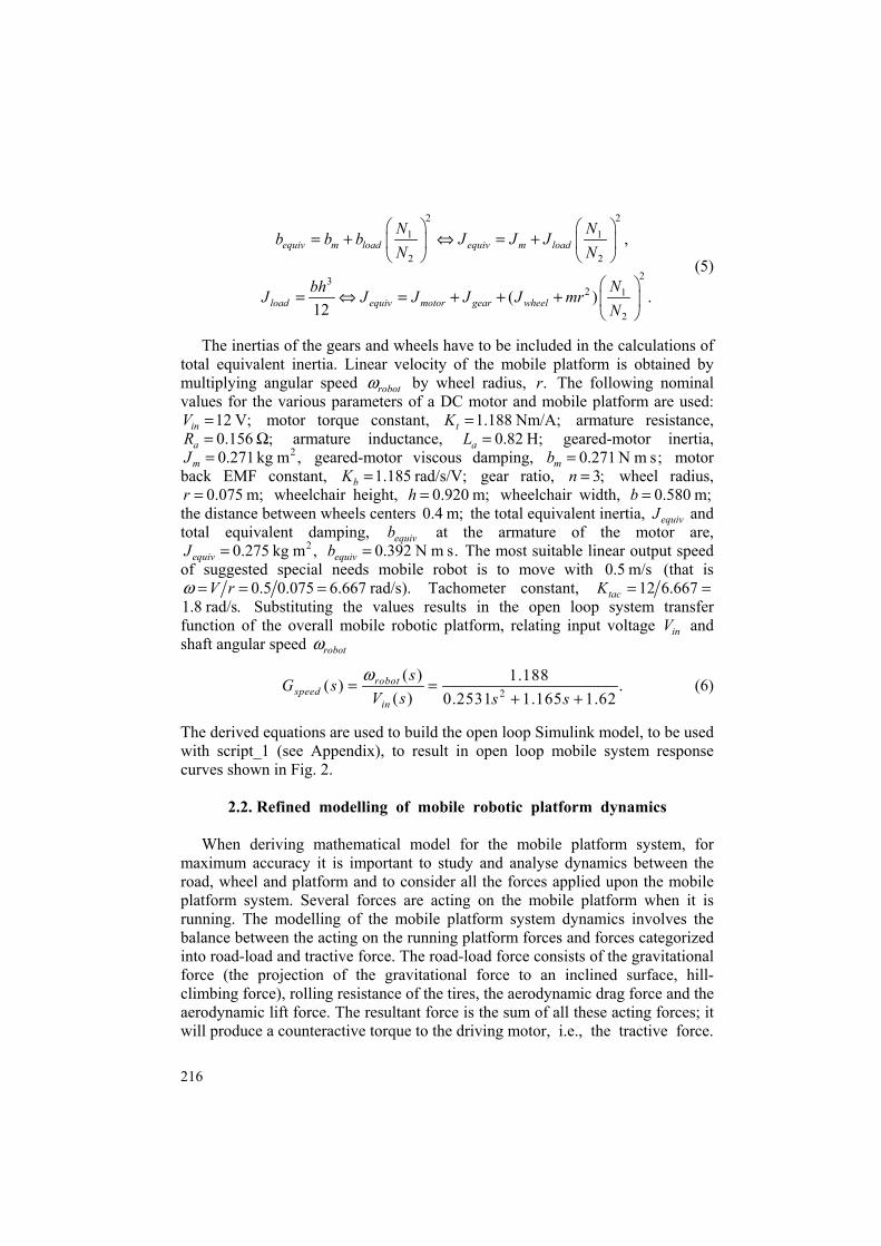
The inertias of the gears and wheels have to be included in the calculations of total equivalent inertia. Linear velocity of the mobile platform is obtained by multiplying angular speed robotω by wheel radius, .r The following nominal values for the various parameters of a DC motor and mobile platform are used:
12 V;inV = motor torque constant, 1.188 Nm/A;tK = armature resistance, 0.156 ;aR = Ω armature inductance, 0.82 H;aL = geared-motor inertia,
20.271 kg m ,mJ = geared-motor viscous damping, 0.271 N m s;mb = motor back EMF constant, 1.185 rad/s/V;bK = gear ratio, 3;n = wheel radius,
0.075 m;r = wheelchair height, 0.920 m;h = wheelchair width, 0.580 m;b = the distance between wheels centers 0.4 m; the total equivalent inertia, equivJ and total equivalent damping, equivb at the armature of the motor are,
20.275 kg m ,equivJ = 0.392 N m s.equivb = The most suitable linear output speed of suggested special needs mobile robot is to move with 0.5 m/s (that is
0.5 0.075 6.667 rad/s).V rω = = = Tachometer constant, 12 6.667tacK = = 1.8 rad/s. Substituting the values results in the open loop system transfer function of the overall mobile robotic platform, relating input voltage inV and shaft angular speed robotω
2( ) 1.188( )
0.2531 1.165 1.62.
( )robot
speedin
sG sss sV
ω+ +
= = (6)
The derived equations are used to build the open loop Simulink model, to be used with script_1 (see Appendix), to result in open loop mobile system response curves shown in Fig. 2.
2.2. Refined modelling of mobile robotic platform dynamics When deriving mathematical model for the mobile platform system, for
maximum accuracy it is important to study and analyse dynamics between the road, wheel and platform and to consider all the forces applied upon the mobile platform system. Several forces are acting on the mobile platform when it is running. The modelling of the mobile platform system dynamics involves the balance between the acting on the running platform forces and forces categorized into road-load and tractive force. The road-load force consists of the gravitational force (the projection of the gravitational force to an inclined surface, hill-climbing force), rolling resistance of the tires, the aerodynamic drag force and the aerodynamic lift force. The resultant force is the sum of all these acting forces; it will produce a counteractive torque to the driving motor, i.e., the tractive force.

217
0 5 100
2
4
6
Time, s
Rad
/s
Angular speed/time
0 5 100
0.1
0.2
0.3
0.4
Time, s
m/s
Linear speed/time
0 5 100 2 4 6 8
Time, s
Amp
Current/time
0 5 100 2 4 6 8
Time, s
Nm
Torque/time
Fig. 2. Open loop mobile robot system: torque/time, angular speed/time, current/time and linear speed/time, response curves for 12 V input.
α
Mg
Road incl.
r =ν/ω
Fig. 3. Forces acting on the moving mobile robotic platform.
Figure 3 shows that changes in the road surface inclination angle, ,α is a disturbance introduced to the system. Therefore controller to be designed is to be robust and should have a disturbance rejection. The disturbance torque to mobile platform is the total resultant torque, generated by the acting forces, and can be expressed as
Lin_a ang_a ,T a R cF F F F F F= + + + + (7)
where RF is the rolling resistance force, aF is the aerodynamic drag force, cF is the hill-climbing resistance force. The driving force comes from the powertrain shaft torque, which can be written as the wheel torque
,wheel shaftT n Tη= (8)

218
where n is the gearing ratio, η is the transmission efficiency and shaftT is the torque, produced by the driving motor. This wheel torque provides the resultant driving, tractive force, TF to the platform, and referring to Fig. 3, the relation-ship between the resultant tractive force and the torque produced by the motor
,sT can be obtained as shown in Eq. (9). The platform inertia torque can be defined by Eq. (10). It is required to couple the mobile platform with the wheel rotational velocity via characteristics of the electric motor and surface such as the traction force, the torque, etc. The relationship between the linear velocity of the platform, ,v and the angular velocity of the electric motor, is given by Eq. (11):
,shaftwheeltotal shaft total
n TT rF T Fr r n
ηη
= = ⇒ = (9)
d,
dvehicle
vehicleT Jt
ω= (10)
,rnωυ = (11)
where r is the tire radius of the mobile platform, υ is the velocity of the platform, ω is the angular velocity of the motor. We are now going to derive expressions for the acting forces, to calculate required torque and power that are to be used to build the Simulink models. 2.2.1. Rolling resistance force, RF
Rolling resistance force is produced by flattening of the tire at the contact surface of the roadway. The rolling resistance force is conservative force with the possibility to partly recover, it depends on the platform’s speed and it is proportional to the platform weight. It is given by
_ cos ,R n f r rF F C Mg C α= = (12)
where M is the mass of the electric platform and cargo ( ),Kg g is the gravity acceleration (m/s2), υ is the platform linear speed, rC is the rolling resistance coefficient (it is the force needed to push or tow a wheeled platform forward, can be determined experimentally) and rC is calculated by the following expression:
3.60.01 1 .100r robotC υ = +
The rolling resistance torque is given by
( cos ) .R rT MgC rα= (13)
219
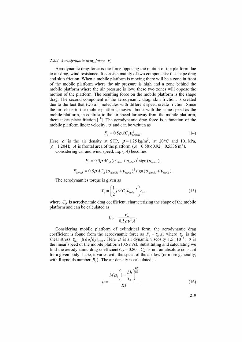
2.2.2. Aerodynamic drag force, aF
Aerodynamic drag force is the force opposing the motion of the platform due to air drag, wind resistance. It consists mainly of two components: the shape drag and skin friction. When a mobile platform is moving there will be a zone in front of the mobile platform where the air pressure is high and a zone behind the mobile platform where the air pressure is low; these two zones will oppose the motion of the platform. The resulting force on the mobile platform is the shape drag. The second component of the aerodynamic drag, skin friction, is created due to the fact that two air molecules with different speed create friction. Since the air, close to the mobile platform, moves almost with the same speed as the mobile platform, in contrast to the air speed far away from the mobile platform, there takes place friction [11]. The aerodynamic drag force is a function of the mobile platform linear velocity, υ and can be written as
20.5 .a d vehicleF ACρ υ= (14)
Here ρ is the air density at STP, 31.25 kg/m ,ρ = at 20 °C and 101 kPa, 1.2041;ρ = A is frontal area of the platform 2( 0.58 0.92 0.5336 m ).A = × =
Considering car and wind speed, Eq. (14) becomes
20.5 ( ) sign ( ),a d robot wind robotF ACρ υ υ υ= +
20.5 ( ) sign ( ).aerod d vehicle wind vehicle windF ACρ υ υ υ υ= + +
The aerodynamics torque is given as
21 ,2a d robot wT AC rρ υ =
(15)
where dC is aerodynamic drag coefficient, characterizing the shape of the mobile platform and can be calculated as
2 .0.5
ad
FCAρυ
=
Considering mobile platform of cylindrical form, the aerodynamic drag coefficient is found from the aerodynamic force as ,a mF Aτ= where mτ is the shear stress m 0d d | .yu yτ µ == Here µ is air dynamic viscosity 51.5 10 ,−× υ is the linear speed of the mobile platform (0.5 m/s). Substituting and calculating we find the aerodynamic drag coefficient 0.80.dC = dC is not an absolute constant for a given body shape, it varies with the speed of the airflow (or more generally, with Reynolds number ).eR The air density is calculated as
00
1
gmRLLhM
TRT
ρρ
−
= , (16)

220
where 0 101325 Pa,ρ = sea level standard atmospheric pressure, 0 288.15 KT = (sea level standard temperature), 29.81 m/sG = is the earth-surface gravitational acceleration, 0.0065 K/mL = is the temperature lapse rate, R = 8.31447 J/(mol K)⋅ universal gas constant, 0.0289644 kg/molM = molar mass of dry air.
2.2.3. The aerodynamics lift force, LF
It is caused by pressure difference between the mobile platform’s roof and underside, and is expressed as
20.5 ,L L robotF C Bρ υ= (17)
where B is the mobile platform’s reference area, LC is the coefficient of lift, ( LC is 0.10 or 0.16), and can be calculated using the following expression:
2 ,0.5L
LCAρυ
=
where L is lift and ρ is the air density at STP, 1.2041.ρ = While the mobile platform is moving up or down the hill, the weight of the
mobile platform will create a hill-climbing resistance force directed downward. This force will oppose or contribute to the motion. It is a conservative force, with the possibility to partly recover. The component of gravity in the dimension of travel is the hill-climbing resistance force
sin ,CF Mg α= (18)
where M is the mass of the mobile platform (mobile robot) and cargo (Kg) g, α is the road or the hill climbing angle, road slope (rad.). The hill-climbing resistance, slope torque, is given by:
= ( sin ) .C slope wT T Mg rα= (19)
2.2.4. The normal force normF
normF is the force exerted by the road on the mobile platform’s tires, the magnitude of nF equals the magnitude of the accF in the direction normal to the road. The normal force normF can be found as
2( sin ) (0.5 ).norm climb lift LF F F Mg C Bα ρ υ= − = − (20)
2.2.5. The linear acceleration force accF
accF is the force required to increase the speed of the mobile platform and can be described as a linear motion given by:

221
2d d ,d d
wheelacc
JF Ma M M
t trυ υ = = = +
(21)
d ,dacc
TF Ma M M
t Jω= = = ∑
where M is the mass of the mobile platform (mobile robot and cargo), a is acceleration experienced as a result of the force exerted by the motors or as a rotational movement, T∑ is the resultant torque acting on the wheels (Nm), J is the total inertia of the mobile platform (kgM
2), wheelJ is the inertia of the wheel (kgM
2). 2.2.6. The angular acceleration force _acc angleF
It is the force required by the wheels to make angular acceleration and is given by
2
_ 2 .acc anglew
GF J ar
= (22)
The angular acceleration torque is expressed as
2 2
_ 2 .acc angle wheelw w
G GF r J a J ar r
= = (23)
The needed energy of the mobile platform, the requested power in kW that mobile platform must develop at stabilized speed, can be determined by multiplying the total force with the velocity of the platform:
( ) .total totalP Fυ υ= =Σ (24)
Substituting derived force equations as well as torque terms equations into Eq. (1), and applying the total torque to electric motor equation, will result in a mathematical model of mobile platform dynamics. Based on the equations that describe the DC motor, system dynamics and sensor modelling, the next open loop transfer function, relating the armature input terminal voltage, ( )inV s to the output terminal voltage of the tachometer ( ),tachV s with most corresponding load torques applied, is
( )( ) ,
( ) ( )( ) ( )in s t
opentach a a m m a a b t
V s K KG s
V s L s R J s b L s R T K K=
+ + + + +
where T is the disturbance torque. The transfer function of torques including coulomb friction is

222
2 2 2
( )
2 .2 2 2 2 2
open
s t
equiv a a equiv a a r a equiv a b t r a equiv a
G s
K Kb L s r ML s b R s r MR s C L s J L s K K C R J R
=
+ + + + + + + +
(25)
3. CONTROLLER SELECTION, DESIGN AND TESTING
The most basic design requirements of a given electric DC motor are to rotate at desired angular speed d dtω θ= and to achieve desired angular position, ,θ at the minimum possible steady-state error ;sse also the motor must accelerate to its steady-state speed, 2 2d dtα θ= as soon as it turns on. Different resources introduce different methodologies and approaches for mobile robot modelling and controller selection and design. For instant, in [3] modelling and control of a mobile robot using deadbeat response is introduced. In [11], different control strategies are used and tested for modelling and controller design of a DC motor. Suggested model allows user to select most used speed controllers of a mobile robot, separate PID, PI, and PD also as well as PI, PID and PI with deadbeat response control strategies to control the suggested models and function block.
3.1. Sensor modelling
Tachometer is a sensor used to measure the actual output angular speed, .Lω
Dynamics of a tachometer can be represented using the expression
d ( )( ) ( ) ( ) ( ).dout s out s s out
tV t K V t K K V s st
θ ω ω= ⇒ = ⇒ =
We are to drive our robotic platform system with linear velocity of 0.5 and 1 m/s. The angular speed is obtained as
0.5 16.6667 rad/s 13.3333 rad/s.0.075 0.075
Vr
ω ω= = = ⇔ = =
Therefore, the tachometer constants, for 6.6667ω = and 13.3333, are given as
12 12 1.8 0.9.6.6667 13.3333s sK K= = ⇔ = =
3.2. Controller selection and design for the simplified model
3.2.1. Applying PID controller PID controllers are ones of most used to achieve the desired time-domain
behaviour of many different types of dynamic plants. The sign of the controller’s output will determine the direction in which the motor will turn. PID controller transfer function can be written as

223
22
.
P ID
D DI D P IPID P D
K KK s sK KK K s K s KG K K
s s s
+ + + + = + + = =
The Simulink model of the closed loop mobile robotic platform, applying PID controller with gains ( 36.5147914490382,PK = 3.9993103795440289,IK =
8.72627529001082,DK = 75),N = is shown in Fig. 4. Running this model will result in response curves shown in Fig. 5. Based on these response curves, several observations can be made. For 12 V input, the mobile platform will smoothly reach desired output linear speed of 0.5 m/s in 1.5 s, without overshoot, with linear max acceleration of 1.7 m/s2. The mobile platform system draws current about 7.9 A peak and about 7.7 A continuous in operation.
Fig. 4. Closed loop mobile platform with tachometer and PID controller.
0 2 4 6-1
0
1
2
Time, s
m/s
Linear acceleration α
0 2 4 60
0.2 0.4 0.6 0.8
Time, s
M
Linear speed ν
0 2 4 60 2 4 6 8
Time, s
A
Current/time
0 2 4 60
5
10
Time, s
Nm
Torque/time
0 2 4 60
2
4
6
8
Time, s
Rad
/s
Angular speed ω
0 2 4 6-20
0
20
40
60
Time, s
Control signal
Fig. 5. Time dependence of the linear speed, linear acceleration, angular speed, current, torque and control signal of the simplified model of close loop mobile platform with PID controller.
224
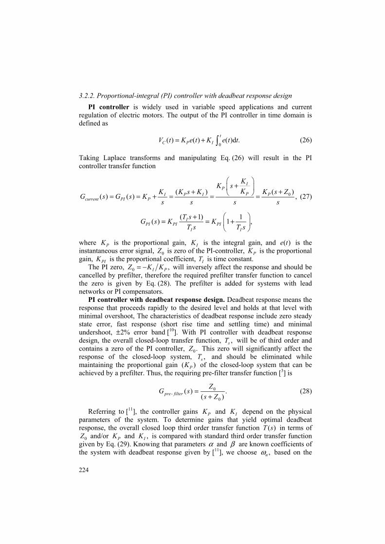
3.2.2. Proportional-integral (PI) controller with deadbeat response design PI controller is widely used in variable speed applications and current
regulation of electric motors. The output of the PI controller in time domain is defined as
0( ) ( ) ( )d .
tC P IV t K e t K e t t= + ∫ (26)
Taking Laplace transforms and manipulating Eq. (26) will result in the PI controller transfer function
0( )( )( ) ( ) ,
IP
P PI P Icurrent PI P
KK sK K s ZK K s KG s G s K
s s s s
+ ++ = = + = = = (27)
( 1) 1( ) 1 ,IPI PI PI
I I
T sG s K KT s T s
+= = +
where PK is the proportional gain, IK is the integral gain, and ( )e t is the instantaneous error signal, 0Z is zero of the PI-controller, PK is the proportional gain, PIK is the proportional coefficient, IT is time constant.
The PI zero, 0 ,I PZ K K= − will inversely affect the response and should be cancelled by prefilter, therefore the required prefilter transfer function to cancel the zero is given by Eq. (28). The prefilter is added for systems with lead networks or PI compensators.
PI controller with deadbeat response design. Deadbeat response means the response that proceeds rapidly to the desired level and holds at that level with minimal overshoot, The characteristics of deadbeat response include zero steady state error, fast response (short rise time and settling time) and minimal undershoot, ± 2% error band [10]. With PI controller with deadbeat response design, the overall closed-loop transfer function, ,sT will be of third order and contains a zero of the PI controller, 0.Z This zero will significantly affect the response of the closed-loop system, ,sT and should be eliminated while maintaining the proportional gain ( )PK of the closed-loop system that can be achieved by a prefilter. Thus, the requiring pre-filter transfer function [3] is
0
0
( ) .( )pre- filter
ZG s
s Z=
+ (28)
Referring to [11], the controller gains PK and IK depend on the physical parameters of the system. To determine gains that yield optimal deadbeat response, the overall closed loop third order transfer function ( )T s in terms of
0Z and/or PK and ,IK is compared with standard third order transfer function given by Eq. (29). Knowing that parameters α and β are known coefficients of the system with deadbeat response given by [11], we choose ,nω based on the

225
desired settling time or rise time. This way we obtain the optimal values of 0Z and/or PK and IK that yield optimal deadbeat response (for third-order system
1.9α = and 2.2):β =
3
3 2 2 3( ) .nstandard
n n n
G ss s s
ωαω βω ω
=+ + +
(29)
Simulink model of the PI controller with deadbeat response is shown in Fig. 6. Replacing PI block with PID controller block, given in model shown in Fig. 3, and adding prefilter (with 2.1932,PK = 4.5154IK = and 0 2.0588)Z = and running the model will result in response curves, shown in Fig. 7. Based on these response curves, several observations can be made, first, for 12 V input, the
Fig. 6. Simulink block of PI controller with deadbeat response.
0 5 10-0.5
0
0.5
1
Time, s
m/s
Linear acceleration α
0 5 10-0.2
0 0.2 0.4 0.6
Time, s
M
Linear speed ν
0 5 100
5
10
Time, s
A
Current/time
0 2 4 60
5
10
Time, s
Nm
Torque/time
0 5 10 0
5
10
Time, s
Rad
/se
Angular speed ω
0 5 10 0
5
10
15
Time, s
Control signal
Fig. 7. Time dependence of the linear speed, linear acceleration, angular speed, current, torque and control signal of the simplified model of close loop mobile platform with PI controller with deadbeat response.
226
mobile platform will smoothly reach desired output linear speed of 0.5 m/s in 2.5 s, without overshoot with linear max acceleration of 0.7 m/s2. Second, the mobile platform system draws about 8.5 A peak and about 7.64 A continuous in operation.
3.3. Controlling medium size model application of the mobile platform with moderate accuracy considering main dynamics
By increasing mobile robot’s dimensions and corresponding parameters, the
following acting forces can affect the performance of its motion: the hill-climbing resistance force, ,climbF aerodynamic drag force, ,aerodF and the linear acceleration force, .accF These forces can be included in the mathematical model (see Eq. (29)) and corresponding Simulink model as shown in Fig. 8:
2 d0.5 sin( ) .dDF AC Mg m
tυρ υ α= + + (30)
Simulink model of PI controller with deadbeat response is shown in Fig. 8, running model will result in response curves, shown in Fig. 9. Based on these response curves, several observations can be made. For 12 V input, the mobile platform will reach desired output linear speed of 0.5 m/s in 2.5 s, with some overshoot, the mobile platform system draws about 7.5 A continuous in operation.
3.4. Controlling the refined model; most dynamics considered
3.4.1. PID controller A closed loop Simulink model of the mobile robotic platform, considering all
dynamics (forces and corresponding torques, ,RF ,aF ,LF ,CF nF and ).accF Simulink model of closed loop system with mobile platform, tachometer and PID controller with gains 0.623624252918818,PK = 1.15839303547577,IK =
0.0353790380687044,DK = − and filter coefficient 17.626942024477,N = is shown in Fig. 10. Running this model will result in response curves shown in Fig. 11, the PID gains can be adjusted using PID tuning block. Several observations can be made. First, for 12 V input, the mobile platform will reach output angular speed of 6.67 rad/s in 3.6 s, that is 0.5 m/s. Second, the mobile robot system draws about 3.5 A peak and about 3.5 A continuous in operation.

227
Fig.
8. M
odel
for c
ontro
lling
the
mod
el fo
r med
ium
mob
ile ro
bots
.

228
0 5 10 0
2
4
6
8
Time, s
Rad
/s
Angular speed/time
0 5 10 0
0.2
0.4
0.6
0.8
Time, s
m/s
Linear speed/time
0 5 10-5
0
5
10
Time, s
A
Current/time
0 5 10-5
0
5
10
Time, s
Nm
Torque/time
Fig. 9. Time dependence of the torque, angular speed, current and linear speed of medium mobile robots model with PI controller with deadbeat response.
3.4.2. Proportional-integral (PI) controller with deadbeat response design
Replacing PID blocks, given in Fig. 6, with deadbeat response block, shown in Fig. 10, running the Simulink model with PI controller and pre-filter with deadbeat response characteristics, for 0 1.9Z = and 1.1,pK = will result in response curves shown in Fig. 12. By adjusting 0Z and ,pK any such desired deadbeat response can be obtained. Several observations can be made. First, for 12 V input, the mobile robot will reach output angular speed of 6.67 rad/s in 2.8 s, that is 0.5 m/s. Second, the mobile robot system draws about 6.2 A peak and about 6.2 A continuous in operation.
4. SUGGESTED FUNCTION BLOCK MODEL To simplify and accelerate the mechatronics design process of mobile robots,
including the physical system, control system and components, as well as to improve the mobile system on both dynamic and steady state performances, a function block model with its function block parameters window for mechatronics mobile robotic platform modelling, testing, validating and controller selection and design (using three controller strategies PID, PI and PI or PI with deadbeat response) is shown in Figs 13 and 14. This model can be modified to include other control strategies. The model has manual switches to switch the model to the required control strategy and input signal. By selecting and defining parameters and values of each DC motor, control strategy, gains, gear ratio, mobile robot dimensions and form (platform and chassis) and running the model will result in
corresponding linear speed/time, angular speed/time, torque/time and current/time

229
Fig.
10.
Ref
ined
Sim
ulin
k m
odel
, of m
obile
robo
tic p
latfo
rm w
ith P
ID c
ontro
ller.

230
response curves as well as visual readings of final steady state values. That all can be used for testing, validating and controller design of the most suitable and desired mobile robot chassis form, dimensions and controller selection.
0 2 4 6 8 0
2
4
6
8
Time, sR
ad/s
Angular speed/time
0 2 4 6 8 0
0.2
0.4
0.6
0.8
Time, s
m/s
Linear speed/time
0 2 4 6 80 1 2 3 4
Time, s
A
Current/time
0 2 4 6 80
2
4
6
Time, s
Nm
Torque/time
Fig. 11. Time dependence of torque, angular speed, current and linear speed of the refined close loop mobile robotic platform model with PID controller.
0 2 4 60 2 4 6 8
Time, s
A
Current/time
0 2 4 6 0
0.2
0.4
0.6
0.8
Time, s
m/s
Linear speed/time
0 2 4 6 0
2
4
6
8
Time, s
Rad
/s
Angular speed/time
0 2 4 60 2 4 6 8
Time, s
Nm
Torque/time
Fig. 12. Time dependence of torque, angular speed, current and linear speed of the refined close loop mobile robotic platform model with Proportional-integral (PI) controller with deadbeat response.

231
Fig.
13.
Ele
ctric
mot
or su
bsys
tem
.

232
Fig.
14.
Sug
gest
ed g
ener
al fu
nctio
n bl
ock
mod
el fo
r mec
hatro
nics
mob
ile p
latfo
rm d
esig
n.

233
0 0.5 1 -5
0
5
10
Time, s
Rad
/s
Angular speed/time
0 0.5 1 -0.2
0
0.2
0.4
0.6
Time, s
m/s
Linear speed/time
0 0.5 10
20
40
60
Time, s
A
Current/time
0 0.5 10
20
40
60
Time, s
Nm
Torque/time
Fig. 15. Time dependence of torque, angular speed, current and linear speed of the refined close loop mobile robotic platform function block model with PID for desired output linear speed of 1 m/s.
To run the suggested model, it is required first to define in MATLAB work-
space the designed mobile platform, dimensions and used DC motor parameters, maximum allowed input voltage and desired output linear speed of the mobile platform. MATLAB Script_1 (see Appendix) can be used to defined the required data. That also will result in open loop transfer function of DC motor used and mobile platform, and calculates the platform total inertia and damping properties. Running the model for desired output linear speed of 0.5 with PID controller, then for desired output linear speed of 1 m/s with PI with deadbeat response will result in response curves shown in Figs 15 and 16.
4.1. Comparing the results Based on the obtained response curves, quantitative comparison of three
mathematical models is made (Table 1). The results show the applicability and accuracy of designs and that, depending on the desired accuracy, PID, PI and PI with deadbeat response are applicable for achieving desired smooth speed of a given mobile robot in suitable time without or with minimum possible overshoot. The controllers’ parameters can be tuned to achieve the desired smooth response.

234
0 2 4 6 -5
0
5
10
15
Time, s
Rad
/s
Angular speed/time
0 2 4 6 -0.5
0
0.5
1
Time, s
m/s
Linear speed/time
0 2 4 60 5
10 15 20
Time, s
A
Current/time
0 2 4 60 5
10 15 20
Time, s
Nm
Torque/time
Fig. 16. Time dependence of torque, angular speed, current and linear speed of the refined close loop mobile robotic platform function block model with PI, with deadbeat response for desired output linear speed of 1 m/s.
Table 1. Comparison of the mathematical models
Simplified model Moderate model Refined model
PID PI-dead PI-dead beat PID
Overshoot – – Minimum 0.02 – Undershoot – – – – TR 1.2 1 1.1 2.5 5T 1.5 1.4 2.5 4.2 Current (peak) 7.9 8.5 7.5 6.5
5. CONCLUSIONS New mathematical, Simulink and function block models for mobile robots
and some considerations regarding mechatronics design and control solutions, are introduced. The presented models are to be used to help in facing the two top challenges in developing mechatronic mobile robots systems, early identifying system level problems and ensuring that all design requirements are met. Testing models for different mobile robots applications for achieving desired response, specification shows the applicability and accuracy of design. Depending on the desired accuracy and size of the designed mobile robot, results show that all the proposed models and the applied three controllers, PID, PI and PI with deadbeat

235
response are applicable for response analysis and evaluation of achieving desired smooth speed in suitable time without or with minimum overshoot.
The proposed models are mainly intended to be used for research purposes in mechatronics design and verification of mobile robots’ design and motion control, but also can be used in motion control systems design verification as well as for the application in educational process. In the future work, it is planned to build a cuboid form mobile robotic platform and perform experimental measurements for the purpose of validating the simulated model.
APPENDIX Script_1: Code for plotting open loop platform system response >> Vin=12 ;Ra=0.1557; La=0.82; Jm=0.271; bm=0.271; b=1.185; Kt=1.1882; n=1;Jm=0.271; bm=0.271; r=0.075; m=100; g=1.98; platform_height=0.920;platform_wedth=0.580; Dist_wheels=0.40;%m, distance between wheels JLoad =(platform_wedth* (platform_height)^3)/12; bLoad = 1.091 ; Jequiv = Jm+ JLoad/(n)^2; bequiv = bm + bLoad/(n)^2; desired_linear_speed=1;% m/s desired_angular_speed= (desired_linear_speed)/r; Ktach =Vin/ desired_angular_speed ; num=[Kt/n]; den=[La*Jequiv (Ra*Jequiv+bequiv*La) (Ra*bequiv+Kt*Kb)]; G_robot_open= tf(num,den), step(12*G_robot_open), sisotool(G_robot_open)
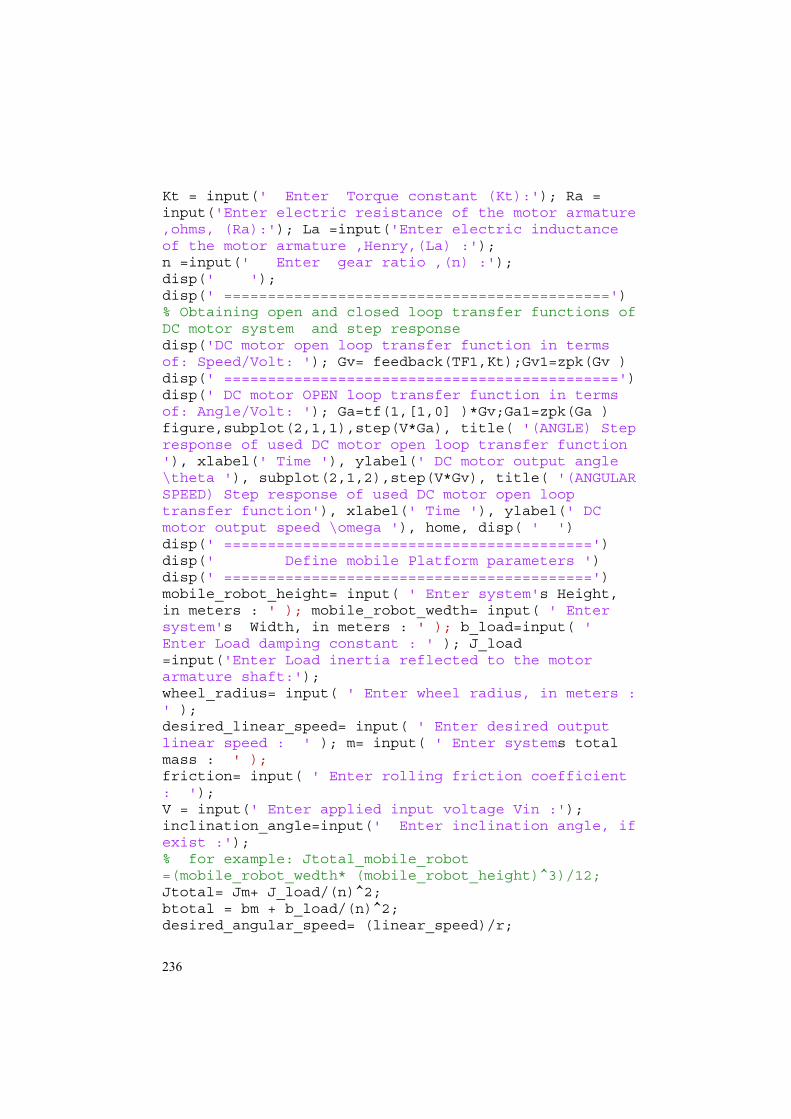
Script_2: Code for defining mobile platform, dimensions, used DC motor parameters, maximum allowed input voltage and desired output linear speed of mobile platform
clc, close all, format short disp( ' ') disp(' ==========================================') disp(' Please define PMDC parameters ') disp(' ==========================================') Jm = input(' Enter Motor armature moment of inertia (Jm) :'); bm = input(' Enter damping constant of the motor system (bm):');Kb = input(' Enter ElectroMotive Force constant (Kb):');
236
Kt = input(' Enter Torque constant (Kt):'); Ra = input('Enter electric resistance of the motor armature ,ohms, (Ra):'); La =input('Enter electric inductance of the motor armature ,Henry,(La) :'); n =input(' Enter gear ratio ,(n) :'); disp(' '); disp(' ============================================') % Obtaining open and closed loop transfer functions of DC motor system and step response disp('DC motor open loop transfer function in terms of: Speed/Volt: '); Gv= feedback(TF1,Kt);Gv1=zpk(Gv ) disp(' =============================================') disp(' DC motor OPEN loop transfer function in terms of: Angle/Volt: '); Ga=tf(1,[1,0] )*Gv;Ga1=zpk(Ga ) figure,subplot(2,1,1),step(V*Ga), title( '(ANGLE) Step response of used DC motor open loop transfer function '), xlabel(' Time '), ylabel(' DC motor output angle \theta '), subplot(2,1,2),step(V*Gv), title( '(ANGULAR SPEED) Step response of used DC motor open loop transfer function'), xlabel(' Time '), ylabel(' DC motor output speed \omega '), home, disp( ' ') disp(' ==========================================') disp(' Define mobile Platform parameters ') disp(' ==========================================') mobile_robot_height= input( ' Enter system's Height, in meters : ' ); mobile_robot_wedth= input( ' Enter system's Width, in meters : ' ); b_load=input( ' Enter Load damping constant : ' ); J_load =input('Enter Load inertia reflected to the motor armature shaft:'); wheel_radius= input( ' Enter wheel radius, in meters : ' ); desired_linear_speed= input( ' Enter desired output linear speed : ' ); m= input( ' Enter systems total mass : ' ); friction= input( ' Enter rolling friction coefficient : '); V = input(' Enter applied input voltage Vin :'); inclination_angle=input(' Enter inclination angle, if exist :'); % for example: Jtotal_mobile_robot =(mobile_robot_wedth* (mobile_robot_height)^3)/12; Jtotal= Jm+ J_load/(n)^2; btotal = bm + b_load/(n)^2; desired_angular_speed= (linear_speed)/r;

237
Ktach =Vin/ desired_angular_speed ;%tachometer constant disp(' =============================================') disp( ' --------------------------------------------') Jtotal= Jm+ J_load/(n)^2; btotal = bm + b_load/(n)^2; desired_angular_speed= (linear_speed)/r; Ktach =Vin/ desired_angular_speed ;%tachometer constant % mobile platform open loop TF num_mobile =Kt*n; den_mobile =[La*Jtotal, (Ra*Jtotal+btotal*La),(Ra* btotal+Kt*Kb)]; mobile_open_tf=tf(num_mobile,den_mobile);
REFERENCES
1. Mahfouz, A. A., Mohammed, M. K. and Salem, F. A. Modeling, simulation and dynamics
analysis issues of electric motor, for mechatronics applications, using different approaches and verification by MATLAB/Simulink (I). Int. J. Intell. Syst. Appl., 2013, 5, 39–57.
2. Mahfouz, A. A., Ayman, A. A. and Salem, F. A. Mechatronics design of a mobile robot system. Int. J. Intell. Syst. Appl., 2013, 5, 23–36.
3. Nouri, B. M. Y. Modeling and control of mobile robot. In Proc. First International Conference on Modeling, Simulation and Applied Optimization. Sharjah, U.A.E., 2005.
4. Hanzell, J., Jurišica, L., Kľúčik, M., Vitko, A. and Strigáč, M. Experimental mobile robotic systems. In Proc. 4th International Conference “Modeling of Mechanical and Mechatronics Systems”. Košice, Slovak Republic, 2011, 20–22.
5. Dezky-Kardoss, E. S. and Kiss, B. L. Design and control of a 2-DOF positioning robot. In Methods and Models in Automation and Robotics. Miedzyzdroje, Poland, 2004, 18–26.
6. Sharifian, M. B. B., Rahnavard, R. and Delavari, H. Velocity control of DC motor based intelligent methods and optimal integral state feedback controller. Int. J. Computer Theory Eng., 2009, 1, 1793–8201.
7. Klančar, G., Matko, D. and Blažič, S. Mobile robot control on a reference path. In Proc. 13th Mediterranean Conference on Control and Automation. Limassol, Cyprus, 2005, 1343–1348.
8. Tao Gong and Zixing Cai. Mobile immune-robot model. In Proc. International Conference on Robotics, Intelligent Systems and Signal Processing. Changsha, China, 2003, vol. 2, 1091–1096.
9. Nwe, A. A., Aung, W. P. and Myint, Y. M. Software implementation of obstacle detection and for wheeled mobile robot avoidance system. World Academy of Science, Engineering and Technology, 2008, 42, 572–577.
10. Dorf, R. C. and Bishop, R. H. Modern Control Systems, 9th ed. Prentice-Hall, New Jersey, 2001.
11. Salem, F. A. and Mahfouz, A. A. Modeling and controller design for PMDC motor, using different control strategies and verification using MATLAB/Simulink (II). Forthcoming.
12. Alasooly, H. Control of DC motor using different control strategies. Global J. Technol. Optimization, 2011, 2, 21–28.
13. Aung, W. P. Analysis on modeling and Simulink of DC motor and its driving system used for wheeled mobile robot. World Academy of Science, Engineering and Technology, 2007, 32, 299–306
14. Shah, B. Field Oriented Control of Step Motors. MSc. Thesis, SVMITB Haruch, India, 2004.

238
15. Gao, D. W. and Emadi, A. Modeling and simulation of electric and hybrid vehicles. Proc. IEEE, 2007, 95, 729–745.
16. Kurfess, T. R. Robotic and Automation Handbook. Washington, D.C., US, 2005. 17. Shahinpoor, M. A Robot Engineering Textbook. Happer & Row Publishers, NY, 1987. 18. MathWorks, 2001. Introduction to MATLAB, the MathWorks, Inc. Control System Toolbox,
MathWorks, Inc.
Täiustatud mudel mobiilse robotplatvormi arendamiseks
Farhan A. Salem On välja töötatud mehhatroonika kontseptsioonid ja täiustatud matemaatiline
mudel mobiilse roboti arendamiseks. Mudel on loodud eesmärgiga pakkuda lahendus kahele peamisele väljakutsele mobiilse robotsüsteemi arenduses: süs-teemi tasemel esinevate probleemide varajane kindlakstegemine ja kõigi nõuete ning kitsenduste täitmise tagamine. Koostatud mudeli realiseerimiseks ja testimi-seks on kasutatud Simulinki tarkvara. Testmudelite käivitamistel saadud tulemusi on võrreldud lihtsamate ja vähem täpsete üldtuntud mudelitega (PID, PI). Kokkuvõttes võib öelda, et töö autori koostatud mudel on rakendatav nagu ka PID- või PI-mudelid, kuid on täpsem.
Related Documents