REFERENCE MANUAL OF WORKER SWITCH (WSW) Confidential Ver.4

Welcome message from author
This document is posted to help you gain knowledge. Please leave a comment to let me know what you think about it! Share it to your friends and learn new things together.
Transcript

REFERENCE MANUAL OFWORKER SWITCH (WSW)
Confidential
Ver.4
i Confidential
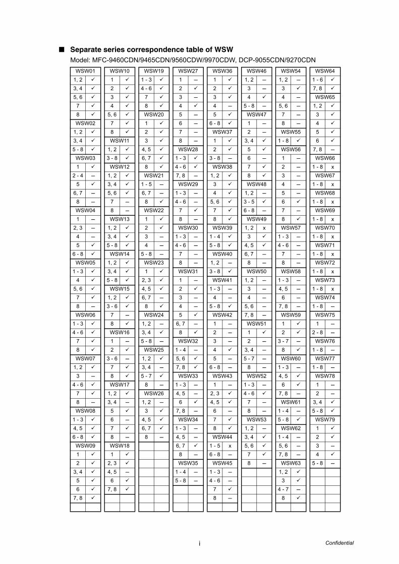
Separate series correspondence table of WSWModel: MFC-9460CDN/9465CDN/9560CDW/9970CDW, DCP-9055CDN/9270CDN
WSW01 WSW10 WSW19 WSW27 WSW36 WSW46 WSW54 WSW641, 2 1 1 - 3 1 - 1 1, 2 - 1, 2 - 1 - 63, 4 2 4 - 6 2 2 3 - 3 7, 85, 6 3 7 3 - 3 4 4 - WSW65
7 4 8 4 4 - 5 - 8 - 5, 6 - 1, 28 5, 6 WSW20 5 - 5 WSW47 7 - 3WSW02 7 1 6 - 6 - 8 1 - 8 - 4
1, 2 8 2 7 - WSW37 2 - WSW55 53, 4 WSW11 3 8 - 1 3, 4 1 - 8 65 - 8 1, 2 4, 5 WSW28 2 5 WSW56 7, 8 -
WSW03 3 - 8 6, 7 1 - 3 3 - 8 - 6 - 1 - WSW661 WSW12 8 4 - 6 WSW38 7 2 - 1 - 8 x
2 - 4 - 1, 2 WSW21 7, 8 - 1, 2 8 3 - WSW675 3, 4 1 - 5 - WSW29 3 WSW48 4 - 1 - 8 x
6, 7 - 5, 6 6, 7 - 1 - 3 - 4 1, 2 - 5 - WSW688 - 7 - 8 4 - 6 - 5, 6 3 - 5 6 1 - 8 xWSW04 8 - WSW22 7 7 6 - 8 - 7 - WSW691 - WSW13 1 8 - 8 WSW49 8 1 - 8 x
2, 3 - 1, 2 2 WSW30 WSW39 1, 2 x WSW57 WSW704 - 3, 4 3 - 1 - 3 - 1 - 4 3 1 - 3 - 1 - 8 x5 5 - 8 4 - 4 - 6 - 5 - 8 4, 5 4 - 6 - WSW71
6 - 8 WSW14 5 - 8 - 7 - WSW40 6, 7 - 7 - 1 - 8 xWSW05 1, 2 WSW23 8 - 1, 2 - 8 - 8 - WSW72
1 - 3 3, 4 1 WSW31 3 - 8 WSW50 WSW58 1 - 8 x4 5 - 8 2, 3 1 - WSW41 1, 2 - 1 - 3 - WSW73
5, 6 WSW15 4, 5 2 1 - 3 - 3 - 4, 5 - 1 - 8 x7 1, 2 6, 7 - 3 - 4 - 4 - 6 - WSW748 - 3 - 6 8 4 - 5 - 8 5, 6 - 7, 8 - 1 - 8 -WSW06 7 - WSW24 5 WSW42 7, 8 - WSW59 WSW75
1 - 3 8 1, 2 - 6, 7 - 1 - WSW51 1 1 -4 - 6 WSW16 3, 4 8 2 - 1 2 2 - 8 -
7 1 - 5 - 8 - WSW32 3 - 2 - 3 - 7 - WSW768 2 WSW25 1 - 4 - 4 3, 4 - 8 1 - 8 -WSW07 3 - 6 - 1, 2 5, 6 5 - 5 - 7 - WSW60 WSW77
1, 2 7 3, 4 - 7, 8 6 - 8 - 8 - 1 - 3 - 1 - 8 -3 - 8 5 - 7 WSW33 WSW43 WSW52 4, 5 WSW78
4 - 6 WSW17 8 - 1 - 3 - 1 - 1 - 3 - 6 1 -7 1, 2 WSW26 4, 5 - 2, 3 4 - 6 7, 8 - 2 -8 - 3, 4 - 1, 2 - 6 4, 5 7 - WSW61 3, 4WSW08 5 3 7, 8 - 6 - 8 - 1 - 4 - 5 - 8
1 - 3 6 - 4, 5 WSW34 7 WSW53 5 - 8 WSW794, 5 7 6, 7 1 - 3 - 8 1, 2 - WSW62 16 - 8 8 - 8 - 4, 5 - WSW44 3, 4 1 - 4 - 2
WSW09 WSW18 6, 7 1 - 5 x 5, 6 5, 6 - 3 -1 1 8 - 6 - 8 - 7 7, 8 - 42 2, 3 WSW35 WSW45 8 - WSW63 5 - 8 -
3, 4 4, 5 - 1 - 4 - 1 - 3 - 1, 25 6 5 - 8 - 4 - 6 - 36 7, 8 7 4 - 7 -
7, 8 8 - 8
ii Confidential
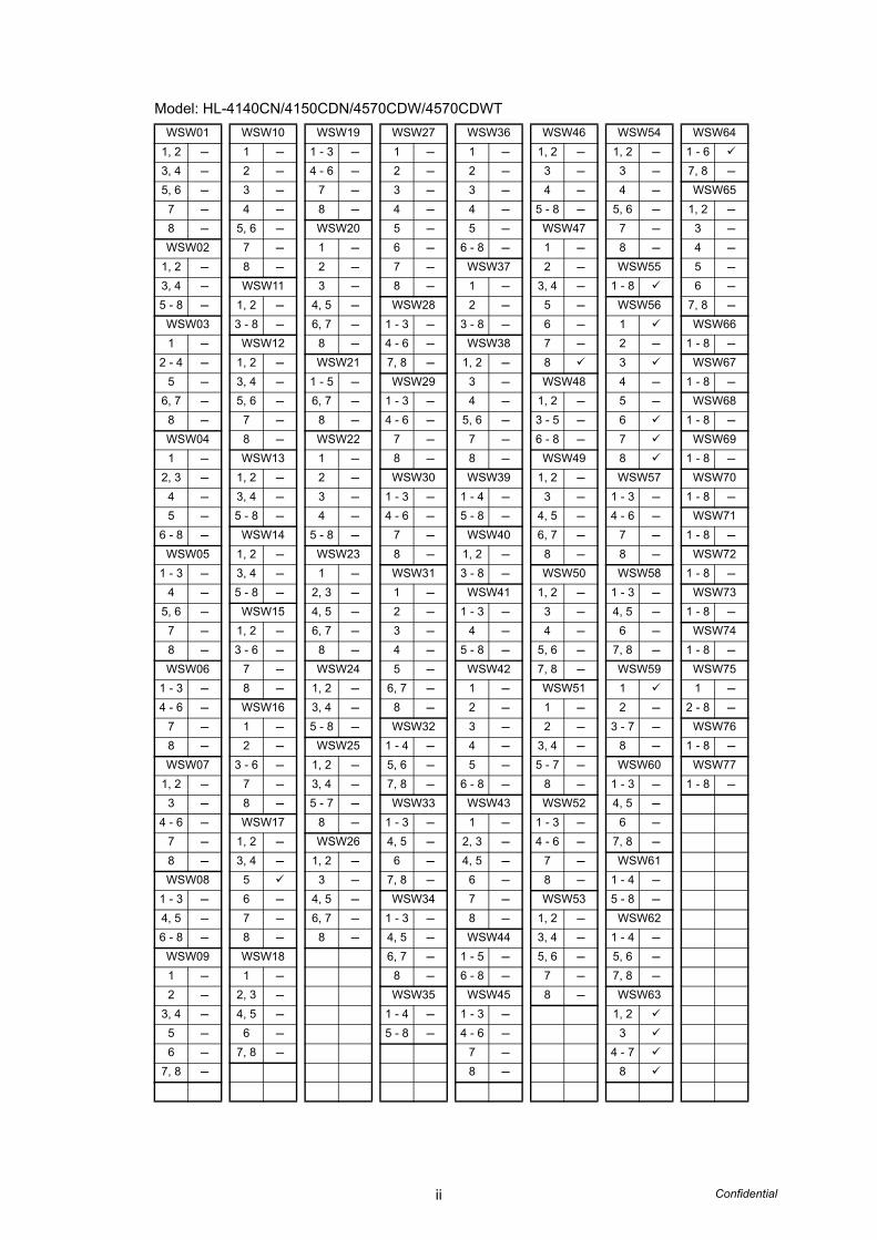
Model: HL-4140CN/4150CDN/4570CDW/4570CDWT WSW01 WSW10 WSW19 WSW27 WSW36 WSW46 WSW54 WSW64
1, 2 - 1 - 1 - 3 - 1 - 1 - 1, 2 - 1, 2 - 1 - 63, 4 - 2 - 4 - 6 - 2 - 2 - 3 - 3 - 7, 8 -5, 6 - 3 - 7 - 3 - 3 - 4 - 4 - WSW65
7 - 4 - 8 - 4 - 4 - 5 - 8 - 5, 6 - 1, 2 -8 - 5, 6 - WSW20 5 - 5 - WSW47 7 - 3 -WSW02 7 - 1 - 6 - 6 - 8 - 1 - 8 - 4 -
1, 2 - 8 - 2 - 7 - WSW37 2 - WSW55 5 -3, 4 - WSW11 3 - 8 - 1 - 3, 4 - 1 - 8 6 -5 - 8 - 1, 2 - 4, 5 - WSW28 2 - 5 - WSW56 7, 8 -
WSW03 3 - 8 - 6, 7 - 1 - 3 - 3 - 8 - 6 - 1 WSW661 - WSW12 8 - 4 - 6 - WSW38 7 - 2 - 1 - 8 -
2 - 4 - 1, 2 - WSW21 7, 8 - 1, 2 - 8 3 WSW675 - 3, 4 - 1 - 5 - WSW29 3 - WSW48 4 - 1 - 8 -
6, 7 - 5, 6 - 6, 7 - 1 - 3 - 4 - 1, 2 - 5 - WSW688 - 7 - 8 - 4 - 6 - 5, 6 - 3 - 5 - 6 1 - 8 -WSW04 8 - WSW22 7 - 7 - 6 - 8 - 7 WSW691 - WSW13 1 - 8 - 8 - WSW49 8 1 - 8 -
2, 3 - 1, 2 - 2 - WSW30 WSW39 1, 2 - WSW57 WSW704 - 3, 4 - 3 - 1 - 3 - 1 - 4 - 3 - 1 - 3 - 1 - 8 -5 - 5 - 8 - 4 - 4 - 6 - 5 - 8 - 4, 5 - 4 - 6 - WSW71
6 - 8 - WSW14 5 - 8 - 7 - WSW40 6, 7 - 7 - 1 - 8 -WSW05 1, 2 - WSW23 8 - 1, 2 - 8 - 8 - WSW72
1 - 3 - 3, 4 - 1 - WSW31 3 - 8 - WSW50 WSW58 1 - 8 -4 - 5 - 8 - 2, 3 - 1 - WSW41 1, 2 - 1 - 3 - WSW73
5, 6 - WSW15 4, 5 - 2 - 1 - 3 - 3 - 4, 5 - 1 - 8 -7 - 1, 2 - 6, 7 - 3 - 4 - 4 - 6 - WSW748 - 3 - 6 - 8 - 4 - 5 - 8 - 5, 6 - 7, 8 - 1 - 8 -WSW06 7 - WSW24 5 - WSW42 7, 8 - WSW59 WSW75
1 - 3 - 8 - 1, 2 - 6, 7 - 1 - WSW51 1 1 -4 - 6 - WSW16 3, 4 - 8 - 2 - 1 - 2 - 2 - 8 -
7 - 1 - 5 - 8 - WSW32 3 - 2 - 3 - 7 - WSW768 - 2 - WSW25 1 - 4 - 4 - 3, 4 - 8 - 1 - 8 -WSW07 3 - 6 - 1, 2 - 5, 6 - 5 - 5 - 7 - WSW60 WSW77
1, 2 - 7 - 3, 4 - 7, 8 - 6 - 8 - 8 - 1 - 3 - 1 - 8 -3 - 8 - 5 - 7 - WSW33 WSW43 WSW52 4, 5 -
4 - 6 - WSW17 8 - 1 - 3 - 1 - 1 - 3 - 6 -7 - 1, 2 - WSW26 4, 5 - 2, 3 - 4 - 6 - 7, 8 -8 - 3, 4 - 1, 2 - 6 - 4, 5 - 7 - WSW61WSW08 5 3 - 7, 8 - 6 - 8 - 1 - 4 -
1 - 3 - 6 - 4, 5 - WSW34 7 - WSW53 5 - 8 -4, 5 - 7 - 6, 7 - 1 - 3 - 8 - 1, 2 - WSW626 - 8 - 8 - 8 - 4, 5 - WSW44 3, 4 - 1 - 4 -
WSW09 WSW18 6, 7 - 1 - 5 - 5, 6 - 5, 6 -1 - 1 - 8 - 6 - 8 - 7 - 7, 8 -2 - 2, 3 - WSW35 WSW45 8 - WSW63
3, 4 - 4, 5 - 1 - 4 - 1 - 3 - 1, 25 - 6 - 5 - 8 - 4 - 6 - 36 - 7, 8 - 7 - 4 - 7
7, 8 - 8 - 8

iii Confidential
Model: MFC-J6310W/J6510DW/J6710DW/J6910DW WSW01 WSW10 WSW18 WSW27 WSW36 WSW46 WSW54 WSW64
1, 2 1 1 1 - 1 - 1, 2 - 1, 2 1 - 6 -3, 4 2 2, 3 2 2 - 3 - 3 7, 8 -5, 6 3 4, 5 - 3 - 3 - 4 4 WSW65
7 4 6 4 4 - 5 - 8 5, 6 1, 2 -8 5, 6 7, 8 5 - 5 WSW47 7 3 -WSW02 7 WSW19 6 6 - 8 1 8 - 4 -
1, 2 8 1 - 3 7 WSW37 2 WSW55 5 -3, 4 WSW11 4 - 6 8 1 3, 4 1 - 8 - 6 -5 - 8 1, 2 7 WSW28 2 5 WSW56 7, 8 -
WSW03 3 - 8 8 1 - 3 3 - 8 - 6 - 1 - WSW661 WSW12 WSW20 4 - 6 WSW38 7 2 - 1 - 8 -
2 - 4 1, 2 1 7, 8 1, 2 8 3 - WSW675 3, 4 2 WSW29 3 WSW48 4 1 - 8 -
6, 7 5, 6 3 1 - 3 4 1, 2 5 WSW688 - 7 4, 5 4 - 6 5, 6 3 - 5 6 1 - 8 -WSW04 8 6, 7 7 7 6 - 8 - 7 - WSW691 - WSW13 8 8 8 WSW49 8 - 1 - 8 -
2, 3 - 1, 2 WSW21 WSW30 WSW39 1, 2 - WSW57 WSW704 - 3, 4 1 - 5 1 - 3 1 - 4 3 - 1 - 3 1 - 8 -5 5 - 8 6, 7 4 - 6 - 5 - 8 4, 5 4 - 6 WSW71
6 - 8 WSW14 8 7 WSW40 6, 7 - 7 1 - 8 -WSW05 1, 2 WSW22 8 1 8 8 WSW72
1 - 3 3, 4 1 WSW31 2 - WSW50 WSW58 1 - 8 -4 5 - 8 2 1 - 3 - 8 1, 2 1 - 3 WSW73
5, 6 WSW15 3 2 WSW41 3 4 1 - 8 -7 1, 2 4 - 3 - 1 - 3 - 4 5 WSW748 - 3 - 6 5 - 8 - 4 - 4 - 5, 6 6 1 - 8 -WSW06 7 WSW23 5 5 - 8 7, 8 7, 8 - WSW75
1 - 3 8 1 6, 7 WSW42 WSW51 WSW59 1 -4 - 6 WSW16 2, 3 8 - 1 1 1 2 - 8 -
7 1 - 4, 5 WSW32 2 2 2 WSW768 2 6, 7 - 1 - 4 3 - 3, 4 3 - 7 1 - 8 -WSW07 3 8 5, 6 4 5 - 7 8 WSW77
1, 2 4 - WSW24 7, 8 5 - 8 WSW60 1 - 8 -3 5 1, 2 WSW33 6 - 8 - WSW52 1 - 3
4 - 6 6 - 3, 4 1 - 3 WSW43 1 - 3 4, 57 7 5 - 8 4, 5 - 1 - 4 - 6 68 - 8 WSW25 6 2, 3 7 - 7, 8WSW08 WSW17 1, 2 7, 8 4, 5 8 WSW61
1 - 3 1, 2 3, 4 - WSW34 6 - WSW53 1 - 4 -4, 5 3, 4 - 5 - 7 1 - 3 7 1, 2 5 - 8 -6 - 8 5 8 - 4, 5 8 3, 4 WSW62
WSW09 6 - WSW26 6, 7 WSW44 5, 6 1 - 4 -1 7 1, 2 - 8 1 - 5 7 5, 6 -2 8 - 3 WSW35 6 - 8 - 8 - 7, 8 -
3, 4 4, 5 1 - 4 WSW45 WSW635 6, 7 5 - 8 - 1 - 3 - 1, 2 -6 8 - 4 - 6 - 3
7, 8 7 - 4 - 78 8 -

iv Confidential
Model: DCP-J525W/J725DW/J925DW, MFC-J280W/J425W/J430W/J435W/J625DW/J825DW/J835DW WSW01 WSW10 WSW18 WSW27 WSW36 WSW45 WSW54 WSW64
1, 2 1 - 1 1 - 1 1 - 3 1, 2 1 - 6 -3, 4 2 2, 3 2 2 4 - 6 3 7, 8 -5, 6 3 4, 5 - 3 - 3 7 4 - WSW65
7 4 6 4 4 - 8 - 5, 6 1, 2 -8 5, 6 7, 8 5 - 5 WSW46 7 3 -WSW02 7 WSW19 6 - 6 - 8 1, 2 8 - 4 -
1, 2 8 1 - 3 7 - WSW37 3 WSW55 5 -3, 4 WSW11 4 - 6 8 - 1 4 1 - 8 - 6 -5 - 8 1, 2 7 WSW28 2 5 - 8 - WSW56 7, 8 -
WSW03 3, 4 8 1 - 3 3 - 8 - WSW47 1 - WSW661 5, 6 WSW20 4 - 6 WSW38 1 2 - 1 - 8 -
2 - 4 7, 8 - 1 7, 8 - 1, 2 2 - 3 - WSW675 WSW12 2 WSW29 3 3, 4 - 4 1 - 8 -
6, 7 - 1, 2 3 1 - 3 - 4 5 - 5 - WSW688 - 3, 4 4, 5 4 - 6 - 5, 6 6 - 6 - 1 - 8 -WSW04 5, 6 6, 7 7 - 7 7 - 7 - WSW691 - 7 - 8 8 - 8 8 8 - 1 - 8 -
2, 3 - 8 - WSW21 WSW30 WSW39 WSW48 WSW57 WSW704 - WSW13 1 - 5 - 1 - 3 - 1 - 4 1, 2 - 1, 2 1 - 8 -5 1, 2 6, 7 - 4 - 6 - 5 - 8 3 - 5 3 - 6 - WSW71
6 - 8 - 3, 4 8 7 - WSW40 6 - 8 - 7 1 - 8 -WSW05 5 - 8 WSW22 8 - 1 - WSW49 8 - WSW72
1 - 3 WSW14 1 WSW31 2 - 1, 2 - WSW58 1 - 8 -4 1, 2 2 1 - 3 - 6 3 - 1 - 3 - WSW73
5, 6 3, 4 3 2 7 - 4, 5 4 - 1 - 8 -7 5 - 8 4 - 3 - 8 6, 7 - 5 - WSW748 - WSW15 5 - 8 - 4 WSW41 8 6 1 - 8 -WSW06 1, 2 WSW23 5 1 - 3 WSW50 7, 8 - WSW75
1 - 3 3 - 6 1 6, 7 - 4 - 1, 2 WSW59 1 -4 - 6 7 - 2, 3 8 - 5 - 8 3 1 2 - 8 -
7 8 4, 5 WSW32 WSW42 4 2 WSW768 WSW16 6, 7 - 1 - 4 - 1 5, 6 3 - 7 1 - 8 -WSW07 1 - 8 5, 6 2 - 7, 8 8 WSW77
1, 2 2 WSW24 7, 8 3 - WSW51 WSW60 1 - 8 -3 - 3 1, 2 - WSW33 4 - 1 1 - 3 -
4 - 6 4 - 3, 4 1 - 3 - 5 - 2 4, 5 -7 5 - 5 - 8 - 4, 5 - 6 - 8 - 3, 4 - 68 - 6 - WSW25 6 WSW43 5 - 7 - 7, 8WSW08 7 1, 2 7, 8 - 1 - 8 - WSW61
1 - 3 8 3, 4 - WSW34 2, 3 WSW52 1 - 4 -4, 5 WSW17 5 - 7 1 - 3 - 4, 5 1 - 3 - 5 - 8 -6 - 8 1, 2 8 - 4, 5 - 6 - 4 - 6 - WSW62
WSW09 3, 4 - WSW26 6, 7 7 7 1 - 4 -1 5 1, 2 - 8 - 8 8 5, 6 -2 6 - 3 WSW35 WSW44 WSW53 7, 8 -
3, 4 7 - 4, 5 1 - 4 - 1 - 5 - 1, 2 WSW635 8 - 6, 7 5 - 8 - 6 - 8 3, 4 - 1, 2 -6 8 - 5, 6 - 3, 4
7, 8 7 5 - 7 -8 - 8

v Confidential
Model: MFC-J5910 WSW01 WSW10 WSW18 WSW27 WSW36 WSW45 WSW54 WSW63
1, 2 1 - 1 1 - 1 1 - 3 1, 2 1, 2 -3, 4 2 2, 3 2 2 4 - 6 3 3, 45, 6 3 4, 5 - 3 - 3 7 4 - 5
7 4 6 4 4 - 8 - 5, 6 6, 7 -8 5, 6 7, 8 5 - 5 WSW46 7 8WSW02 7 WSW19 6 - 6 - 8 1, 2 8 - WSW64
1, 2 8 1 - 3 7 - WSW37 3 WSW55 1 - 6 -3, 4 WSW11 4 - 6 8 - 1 4 1 - 8 - 7, 8 -5 - 8 1, 2 7 WSW28 2 5 - 8 - WSW56 WSW65
WSW03 3 - 8 8 1 - 3 3 - 8 - WSW47 1 - 1, 2 -1 WSW12 WSW20 4 - 6 WSW38 1 2 - 3 -
2 - 4 1, 2 1 7, 8 - 1, 2 2 - 3 - 4 -5 3, 4 2 WSW29 3 3, 4 - 4 5 -
6, 7 - 5, 6 3 1 - 3 - 4 5 - 5 - 6 -8 - 7 - 4, 5 4 - 6 - 5, 6 6 - 6 7, 8 -WSW04 8 - 6, 7 7 - 7 7 - 7 - WSW661 - WSW13 8 8 - 8 8 8 - 1 - 8 -
2, 3 - 1, 2 WSW21 WSW30 WSW39 WSW48 WSW57 WSW674 - 3, 4 1 - 5 - 1 - 3 - 1 - 4 1, 2 - 1, 2 1 - 8 -5 5 - 8 6, 7 - 4 - 6 - 5 - 8 3 - 5 3 - 6 - WSW68
6 - 8 - WSW14 8 7 - WSW40 6 - 8 - 7 1 - 8 -WSW05 1, 2 WSW22 8 - 1 - WSW49 8 WSW69
1 - 3 3, 4 1 WSW31 2 - 1, 2 - WSW58 1 - 8 -4 5 - 8 2 1 - 3 - 6 3 - 1 - 3 - WSW70
5, 6 WSW15 3 2 7 - 4, 5 4 - 1 - 8 -7 1, 2 4 - 3 - 8 6, 7 5 - WSW718 - 3 - 6 5 - 8 - 4 WSW41 8 6 1 - 8 -WSW06 7 - WSW23 5 1 - 3 WSW50 7, 8 - WSW72
1 - 3 8 1 6, 7 - 4 - 1, 2 WSW59 1 - 8 -4 - 6 WSW16 2, 3 8 - 5 - 8 3 1 WSW73
7 1 - 4, 5 WSW32 WSW42 4 2 1 - 8 -8 2 6, 7 - 1 - 4 - 1 5, 6 3 - 7 WSW74WSW07 3 - 8 5, 6 2 - 7, 8 8 1 - 8 -
1, 2 4 - WSW24 7, 8 3 - WSW51 WSW60 WSW753 - 5 - 1, 2 - WSW33 4 - 1 1 - 3 - 1 -
4 - 6 6 - 3, 4 1 - 3 - 5 - 2 - 4, 5 - 2 - 8 -7 7 5 - 8 - 4, 5 - 6 - 8 - 3, 4 - 6 WSW768 - 8 WSW25 6 WSW43 5 - 7 - 7, 8 1 - 8 -WSW08 WSW17 1, 2 7, 8 - 1 - 8 - WSW61 WSW77
1 - 3 1, 2 3, 4 - WSW34 2, 3 WSW52 1 - 4 - 1 - 8 -4, 5 3, 4 - 5 - 7 1 - 3 - 4, 5 1 - 3 - 5 - 8 -6 - 8 5 8 - 4, 5 - 6 - 4 - 6 - WSW62
WSW09 6 - WSW26 6, 7 7 7 1 - 4 -1 7 - 1, 2 - 8 - 8 8 5, 6 -2 8 - 3 WSW35 WSW44 WSW53 7, 8 -
3, 4 4, 5 1 - 4 - 1 - 5 - 1, 25 6, 7 5 - 8 - 6 - 8 3, 4 -6 8 - 5, 6
7, 8 78 -
vi Confidential
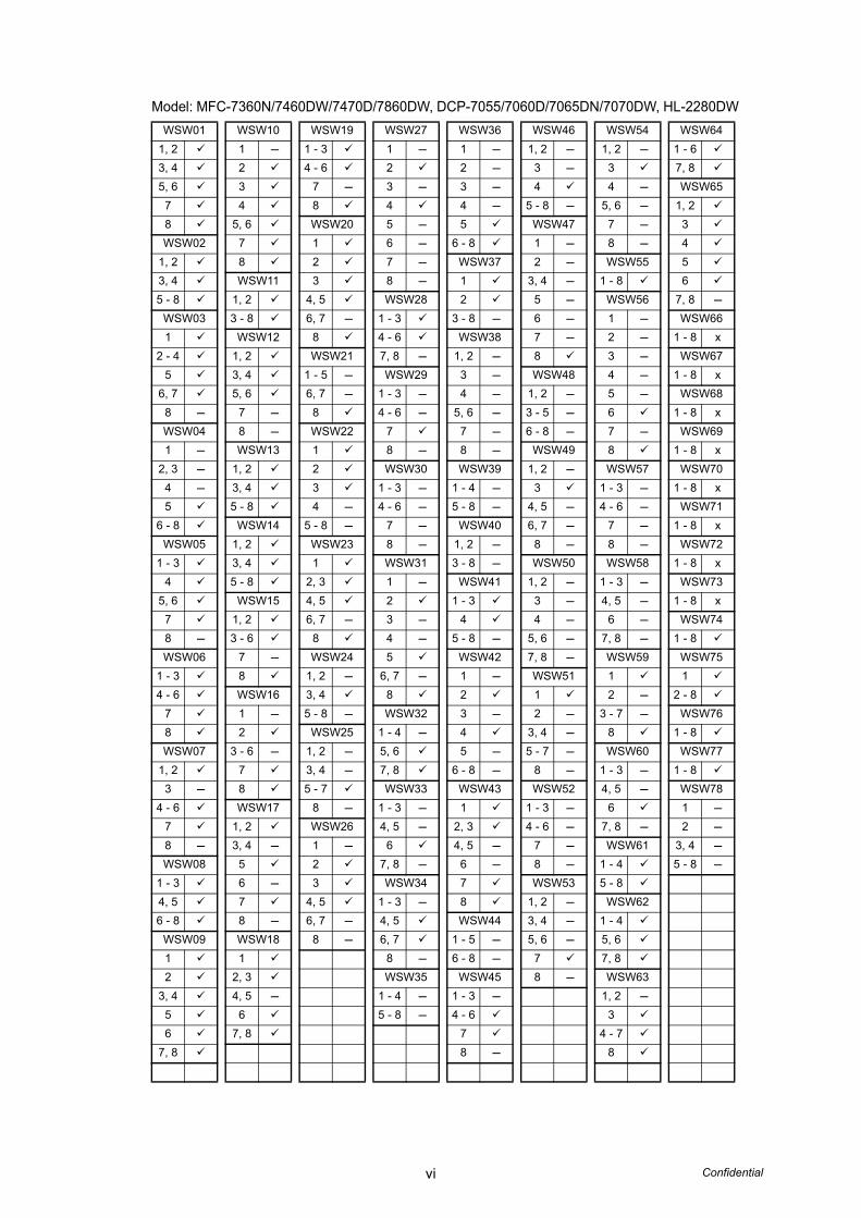
Model: MFC-7360N/7460DW/7470D/7860DW, DCP-7055/7060D/7065DN/7070DW, HL-2280DW WSW01 WSW10 WSW19 WSW27 WSW36 WSW46 WSW54 WSW64
1, 2 1 - 1 - 3 1 - 1 - 1, 2 - 1, 2 - 1 - 63, 4 2 4 - 6 2 2 - 3 - 3 7, 85, 6 3 7 - 3 - 3 - 4 4 - WSW65
7 4 8 4 4 - 5 - 8 - 5, 6 - 1, 28 5, 6 WSW20 5 - 5 WSW47 7 - 3WSW02 7 1 6 - 6 - 8 1 - 8 - 4
1, 2 8 2 7 - WSW37 2 - WSW55 53, 4 WSW11 3 8 - 1 3, 4 - 1 - 8 65 - 8 1, 2 4, 5 WSW28 2 5 - WSW56 7, 8 -
WSW03 3 - 8 6, 7 - 1 - 3 3 - 8 - 6 - 1 - WSW661 WSW12 8 4 - 6 WSW38 7 - 2 - 1 - 8 x
2 - 4 1, 2 WSW21 7, 8 - 1, 2 - 8 3 - WSW675 3, 4 1 - 5 - WSW29 3 - WSW48 4 - 1 - 8 x
6, 7 5, 6 6, 7 - 1 - 3 - 4 - 1, 2 - 5 - WSW688 - 7 - 8 4 - 6 - 5, 6 - 3 - 5 - 6 1 - 8 xWSW04 8 - WSW22 7 7 - 6 - 8 - 7 - WSW691 - WSW13 1 8 - 8 - WSW49 8 1 - 8 x
2, 3 - 1, 2 2 WSW30 WSW39 1, 2 - WSW57 WSW704 - 3, 4 3 1 - 3 - 1 - 4 - 3 1 - 3 - 1 - 8 x5 5 - 8 4 - 4 - 6 - 5 - 8 - 4, 5 - 4 - 6 - WSW71
6 - 8 WSW14 5 - 8 - 7 - WSW40 6, 7 - 7 - 1 - 8 xWSW05 1, 2 WSW23 8 - 1, 2 - 8 - 8 - WSW72
1 - 3 3, 4 1 WSW31 3 - 8 - WSW50 WSW58 1 - 8 x4 5 - 8 2, 3 1 - WSW41 1, 2 - 1 - 3 - WSW73
5, 6 WSW15 4, 5 2 1 - 3 3 - 4, 5 - 1 - 8 x7 1, 2 6, 7 - 3 - 4 4 - 6 - WSW748 - 3 - 6 8 4 - 5 - 8 - 5, 6 - 7, 8 - 1 - 8WSW06 7 - WSW24 5 WSW42 7, 8 - WSW59 WSW75
1 - 3 8 1, 2 - 6, 7 - 1 - WSW51 1 14 - 6 WSW16 3, 4 8 2 1 2 - 2 - 8
7 1 - 5 - 8 - WSW32 3 - 2 - 3 - 7 - WSW768 2 WSW25 1 - 4 - 4 3, 4 - 8 1 - 8WSW07 3 - 6 - 1, 2 - 5, 6 5 - 5 - 7 - WSW60 WSW77
1, 2 7 3, 4 - 7, 8 6 - 8 - 8 - 1 - 3 - 1 - 83 - 8 5 - 7 WSW33 WSW43 WSW52 4, 5 - WSW78
4 - 6 WSW17 8 - 1 - 3 - 1 1 - 3 - 6 1 -7 1, 2 WSW26 4, 5 - 2, 3 4 - 6 - 7, 8 - 2 -8 - 3, 4 - 1 - 6 4, 5 - 7 - WSW61 3, 4 -WSW08 5 2 7, 8 - 6 - 8 - 1 - 4 5 - 8 -
1 - 3 6 - 3 WSW34 7 WSW53 5 - 84, 5 7 4, 5 1 - 3 - 8 1, 2 - WSW626 - 8 8 - 6, 7 - 4, 5 WSW44 3, 4 - 1 - 4
WSW09 WSW18 8 - 6, 7 1 - 5 - 5, 6 - 5, 61 1 8 - 6 - 8 - 7 7, 82 2, 3 WSW35 WSW45 8 - WSW63
3, 4 4, 5 - 1 - 4 - 1 - 3 - 1, 2 -5 6 5 - 8 - 4 - 6 36 7, 8 7 4 - 7
7, 8 8 - 8
1 Confidential
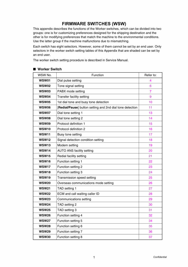
FIRMWARE SWITCHES (WSW)This appendix describes the functions of the Worker switches, which can be divided into two groups: one is for customizing preferences designed for the shipping destination and the other is for modifying preferences that match the machine to the environmental conditions. Use the latter group if the machine malfunctions due to mismatching.
Each switch has eight selectors. However, some of them cannot be set by an end user. Only selectors in the worker switch setting tables of this Appendix that are shaded can be set by an end user.
The worker switch setting procedure is described in Service Manual.
Worker Switch
WSW No. Function Refer to:
WSW01 Dial pulse setting 4
WSW02 Tone signal setting 6
WSW03 PABX mode setting 7
WSW04 Transfer facility setting 9
WSW05 1st dial tone and busy tone detection 10
WSW06 [Redial/Pause] button setting and 2nd dial tone detection 11
WSW07 Dial tone setting 1 13
WSW08 Dial tone setting 2 14
WSW09 Protocol definition 1 15
WSW10 Protocol definition 2 16
WSW11 Busy tone setting 17
WSW12 Signal detection condition setting 18
WSW13 Modem setting 19
WSW14 AUTO ANS facility setting 20
WSW15 Redial facility setting 21
WSW16 Function setting 1 22
WSW17 Function setting 2 23
WSW18 Function setting 3 24
WSW19 Transmission speed setting 25
WSW20 Overseas communications mode setting 26
WSW21 TAD setting 1 27
WSW22 ECM and call waiting caller ID 28
WSW23 Communications setting 29
WSW24 TAD setting 2 30
WSW25 TAD setting 3 31
WSW26 Function setting 4 32
WSW27 Function setting 5 34
WSW28 Function setting 6 35
WSW29 Function setting 7 36
WSW30 Function setting 8 37
2 Confidential
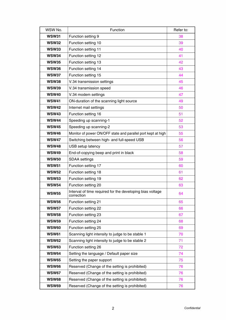
WSW31 Function setting 9 38
WSW32 Function setting 10 39
WSW33 Function setting 11 40
WSW34 Function setting 12 41
WSW35 Function setting 13 42
WSW36 Function setting 14 43
WSW37 Function setting 15 44
WSW38 V.34 transmission settings 45
WSW39 V.34 transmission speed 46
WSW40 V.34 modem settings 47
WSW41 ON-duration of the scanning light source 49
WSW42 Internet mail settings 50
WSW43 Function setting 16 51
WSW44 Speeding up scanning-1 52
WSW45 Speeding up scanning-2 53
WSW46 Monitor of power ON/OFF state and parallel port kept at high 55
WSW47 Switching between high- and full-speed USB 56
WSW48 USB setup latency 57
WSW49 End-of-copying beep and print in black 58
WSW50 SDAA settings 59
WSW51 Function setting 17 60
WSW52 Function setting 18 61
WSW53 Function setting 19 62
WSW54 Function setting 20 63
WSW55 Interval of time required for the developing bias voltage correction 64
WSW56 Function setting 21 65
WSW57 Function setting 22 66
WSW58 Function setting 23 67
WSW59 Function setting 24 68
WSW60 Function setting 25 69
WSW61 Scanning light intensity to judge to be stable 1 70
WSW62 Scanning light intensity to judge to be stable 2 71
WSW63 Function setting 26 72
WSW64 Setting the language / Default paper size 74
WSW65 Setting the paper support 75
WSW66 Reserved (Change of the setting is prohibited) 76
WSW67 Reserved (Change of the setting is prohibited) 76
WSW68 Reserved (Change of the setting is prohibited) 76
WSW69 Reserved (Change of the setting is prohibited) 76
WSW No. Function Refer to:
3 Confidential
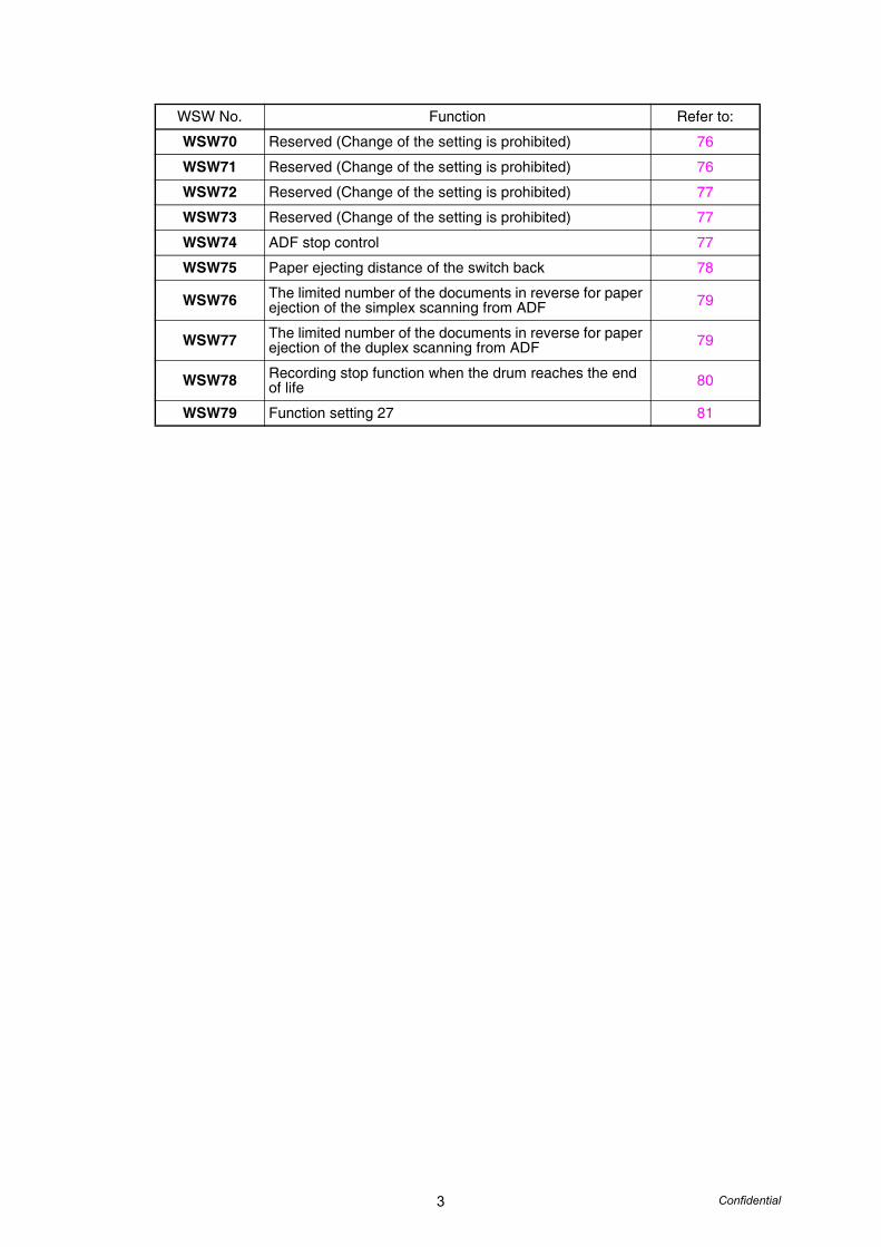
WSW70 Reserved (Change of the setting is prohibited) 76
WSW71 Reserved (Change of the setting is prohibited) 76
WSW72 Reserved (Change of the setting is prohibited) 77
WSW73 Reserved (Change of the setting is prohibited) 77
WSW74 ADF stop control 77
WSW75 Paper ejecting distance of the switch back 78
WSW76 The limited number of the documents in reverse for paper ejection of the simplex scanning from ADF 79
WSW77 The limited number of the documents in reverse for paper ejection of the duplex scanning from ADF 79
WSW78 Recording stop function when the drum reaches the end of life 80
WSW79 Function setting 27 81
WSW No. Function Refer to:
4 Confidential
The functions and settings for each worker switch (WSW) are described below;
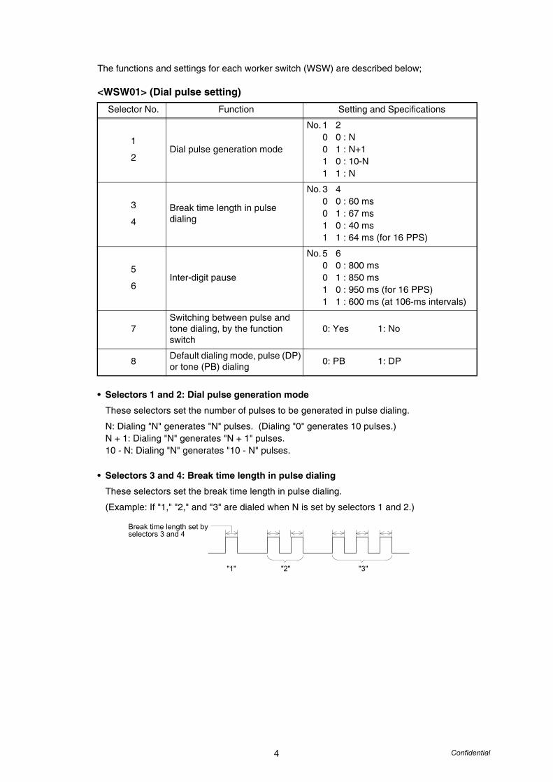
<WSW01> (Dial pulse setting)
• Selectors 1 and 2: Dial pulse generation mode
These selectors set the number of pulses to be generated in pulse dialing.
N: Dialing "N" generates "N" pulses. (Dialing "0" generates 10 pulses.)N + 1: Dialing "N" generates "N + 1" pulses.10 - N: Dialing "N" generates "10 - N" pulses.
• Selectors 3 and 4: Break time length in pulse dialing
These selectors set the break time length in pulse dialing.
(Example: If "1," "2," and "3" are dialed when N is set by selectors 1 and 2.)
Selector No. Function Setting and Specifications
1
2Dial pulse generation mode
No. 1 20 0 : N0 1 : N+11 0 : 10-N1 1 : N
3
4Break time length in pulse dialing
No. 3 40 0 : 60 ms0 1 : 67 ms1 0 : 40 ms 1 1 : 64 ms (for 16 PPS)
5
6Inter-digit pause
No. 5 60 0 : 800 ms0 1 : 850 ms1 0 : 950 ms (for 16 PPS)1 1 : 600 ms (at 106-ms intervals)
7Switching between pulse and tone dialing, by the function switch
0: Yes 1: No
8 Default dialing mode, pulse (DP) or tone (PB) dialing 0: PB 1: DP
"1" "2" "3"
Break time length set by selectors 3 and 4
5 Confidential
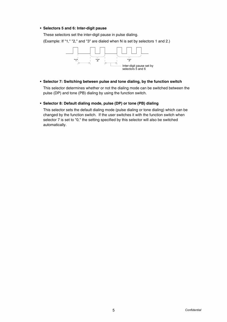
• Selectors 5 and 6: Inter-digit pause
These selectors set the inter-digit pause in pulse dialing.
(Example: If "1," "2," and "3" are dialed when N is set by selectors 1 and 2.)
• Selector 7: Switching between pulse and tone dialing, by the function switch
This selector determines whether or not the dialing mode can be switched between the pulse (DP) and tone (PB) dialing by using the function switch.
• Selector 8: Default dialing mode, pulse (DP) or tone (PB) dialing
This selector sets the default dialing mode (pulse dialing or tone dialing) which can be changed by the function switch. If the user switches it with the function switch when selector 7 is set to "0," the setting specified by this selector will also be switched automatically.
"1" "2" "3"
Inter-digit pause set by selectors 5 and 6
6 Confidential
<WSW02> (Tone signal setting)
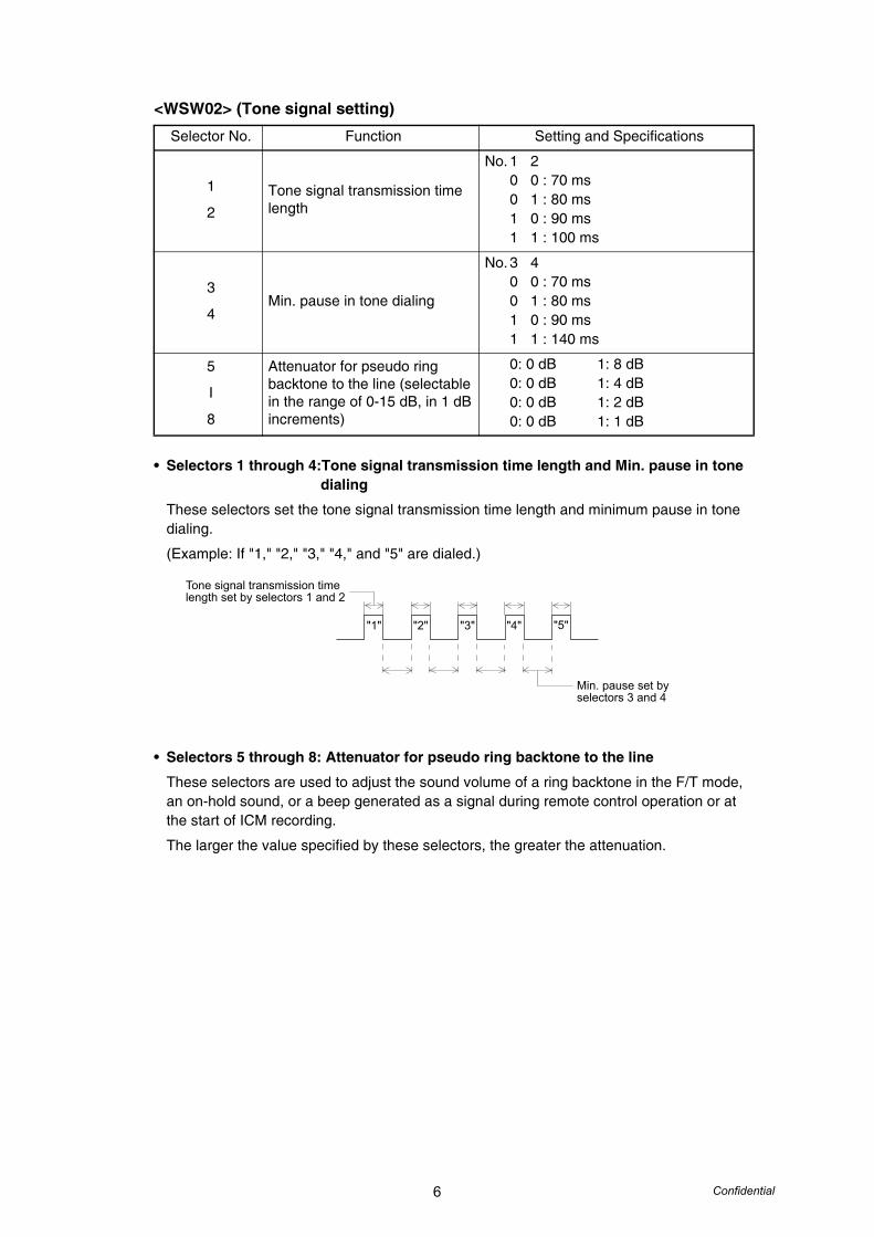
• Selectors 1 through 4:Tone signal transmission time length and Min. pause in tone dialing
These selectors set the tone signal transmission time length and minimum pause in tone dialing.
(Example: If "1," "2," "3," "4," and "5" are dialed.)
• Selectors 5 through 8: Attenuator for pseudo ring backtone to the line
These selectors are used to adjust the sound volume of a ring backtone in the F/T mode, an on-hold sound, or a beep generated as a signal during remote control operation or at the start of ICM recording.
The larger the value specified by these selectors, the greater the attenuation.
Selector No. Function Setting and Specifications
1
2Tone signal transmission time length
No. 1 20 0 : 70 ms0 1 : 80 ms1 0 : 90 ms1 1 : 100 ms
3
4Min. pause in tone dialing
No. 3 40 0 : 70 ms0 1 : 80 ms1 0 : 90 ms1 1 : 140 ms
5
I
8
Attenuator for pseudo ring backtone to the line (selectable in the range of 0-15 dB, in 1 dB increments)
0: 0 dB 1: 8 dB0: 0 dB 1: 4 dB0: 0 dB 1: 2 dB0: 0 dB 1: 1 dB
"1" "2" "3" "4" "5"
Min. pause set by selectors 3 and 4
Tone signal transmission time length set by selectors 1 and 2
7 Confidential
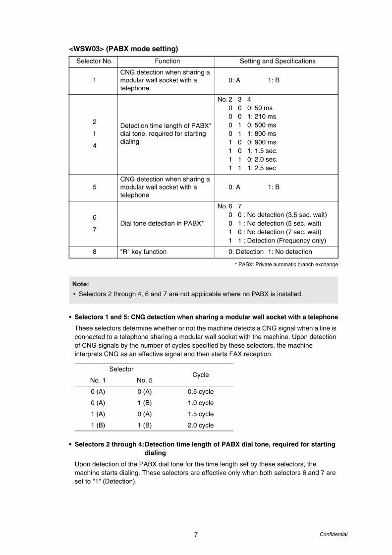
<WSW03> (PABX mode setting)
* PABX: Private automatic branch exchange
• Selectors 1 and 5: CNG detection when sharing a modular wall socket with a telephone
These selectors determine whether or not the machine detects a CNG signal when a line is connected to a telephone sharing a modular wall socket with the machine. Upon detection of CNG signals by the number of cycles specified by these selectors, the machine interprets CNG as an effective signal and then starts FAX reception.
• Selectors 2 through 4:Detection time length of PABX dial tone, required for starting dialing
Upon detection of the PABX dial tone for the time length set by these selectors, the machine starts dialing. These selectors are effective only when both selectors 6 and 7 are set to "1" (Detection).
Selector No. Function Setting and Specifications
1CNG detection when sharing a modular wall socket with a telephone
0: A 1: B
2
I
4
Detection time length of PABX* dial tone, required for starting dialing
No. 2 3 40 0 0: 50 ms0 0 1: 210 ms0 1 0: 500 ms0 1 1: 800 ms1 0 0: 900 ms1 0 1: 1.5 sec.1 1 0: 2.0 sec.1 1 1: 2.5 sec
5CNG detection when sharing a modular wall socket with a telephone
0: A 1: B
6
7Dial tone detection in PABX*
No. 6 70 0 : No detection (3.5 sec. wait)0 1 : No detection (5 sec. wait)1 0 : No detection (7 sec. wait)1 1 : Detection (Frequency only)
8 "R" key function 0: Detection 1: No detection
Note:• Selectors 2 through 4, 6 and 7 are not applicable where no PABX is installed.
SelectorCycle
No. 1 No. 5
0 (A) 0 (A) 0.5 cycle
0 (A) 1 (B) 1.0 cycle
1 (A) 0 (A) 1.5 cycle
1 (B) 1 (B) 2.0 cycle
8 Confidential
• Selectors 6 and 7: Dial tone detection in PABX*
These selectors activate or deactivate the dial tone detection function which detects a dial tone when a line is connected to the PABX.
Setting both of these selectors to "1" activates the dial tone detection function so that the machine starts dialing upon detection of a dial tone when a line is connected.
Other setting combinations deactivate the dial tone detection function so that the machine starts dialing after the specified WAIT (3.5, 5.0, or 7.0 sec.) without detection of a dial tone when a line is connected.
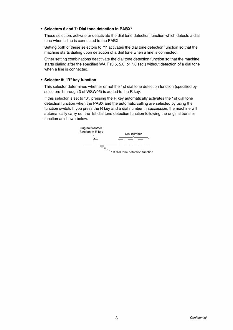
• Selector 8: "R" key function
This selector determines whether or not the 1st dial tone detection function (specified by selectors 1 through 3 of WSW05) is added to the R key.
If this selector is set to "0", pressing the R key automatically activates the 1st dial tone detection function when the PABX and the automatic calling are selected by using the function switch. If you press the R key and a dial number in succession, the machine will automatically carry out the 1st dial tone detection function following the original transfer function as shown below.
Original transferfunction of R key
1st dial tone detection function
Dial number
9 Confidential
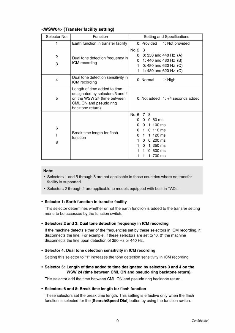
<WSW04> (Transfer facility setting)
• Selector 1: Earth function in transfer facility
This selector determines whether or not the earth function is added to the transfer setting menu to be accessed by the function switch.
• Selectors 2 and 3: Dual tone detection frequency in ICM recording
If the machine detects either of the frequencies set by these selectors in ICM recording, it disconnects the line. For example, if these selectors are set to "0, 0" the machine disconnects the line upon detection of 350 Hz or 440 Hz.
• Selector 4: Dual tone detection sensitivity in ICM recording
Setting this selector to "1" increases the tone detection sensitivity in ICM recording.
• Selector 5: Length of time added to time designated by selectors 3 and 4 on the WSW 24 (time between CML ON and pseudo ring backtone return).
This selector add the time between CML ON and pseudo ring backtone return.
• Selectors 6 and 8: Break time length for flash function
These selectors set the break time length. This setting is effective only when the flash function is selected for the [Search/Speed Dial] button by using the function switch.
Selector No. Function Setting and Specifications
1 Earth function in transfer facility 0: Provided 1: Not provided
2
3Dual tone detection frequency in ICM recording
No. 2 30 0: 350 and 440 Hz (A)0 1: 440 and 480 Hz (B)1 0: 480 and 620 Hz (C)1 1: 480 and 620 Hz (C)
4 Dual tone detection sensitivity in ICM recording 0: Normal 1: High
5
Length of time added to time designated by selectors 3 and 4 on the WSW 24 (time between CML ON and pseudo ring backtone return).
0: Not added 1: +4 seconds added
6
I
8
Break time length for flash function
No. 6 7 80 0 0: 80 ms0 0 1: 100 ms0 1 0: 110 ms0 1 1: 120 ms1 0 0: 200 ms1 0 1: 250 ms1 1 0: 500 ms1 1 1: 700 ms
Note:• Selectors 1 and 5 through 8 are not applicable in those countries where no transfer
facility is supported.
• Selectors 2 through 4 are applicable to models equipped with built-in TADs.
10 Confidential
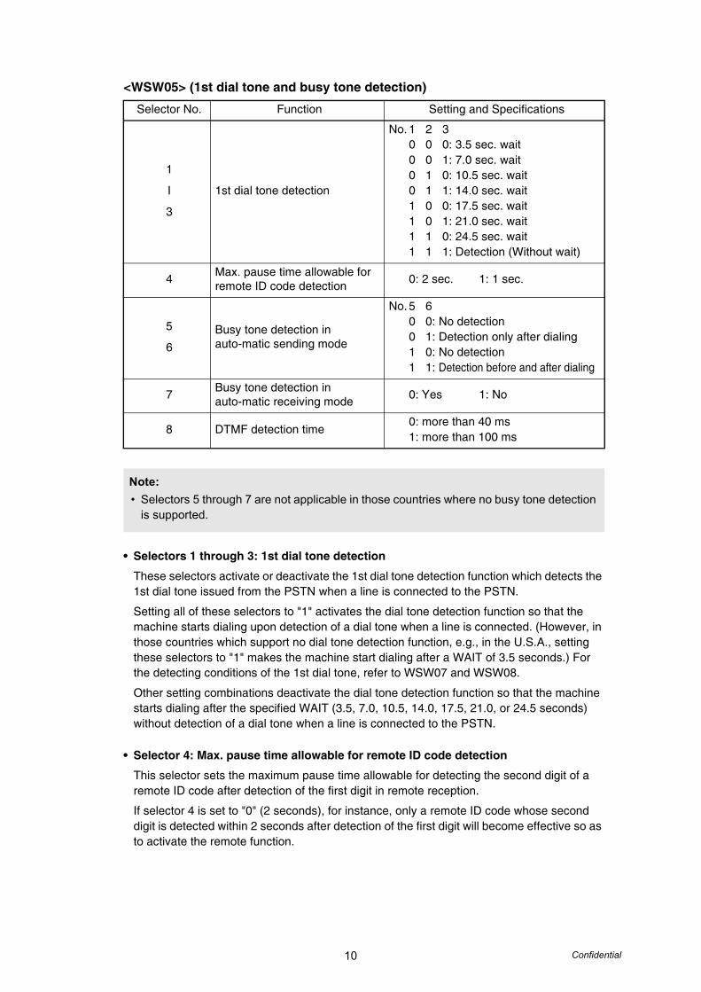
<WSW05> (1st dial tone and busy tone detection)
• Selectors 1 through 3: 1st dial tone detection
These selectors activate or deactivate the 1st dial tone detection function which detects the 1st dial tone issued from the PSTN when a line is connected to the PSTN.
Setting all of these selectors to "1" activates the dial tone detection function so that the machine starts dialing upon detection of a dial tone when a line is connected. (However, in those countries which support no dial tone detection function, e.g., in the U.S.A., setting these selectors to "1" makes the machine start dialing after a WAIT of 3.5 seconds.) For the detecting conditions of the 1st dial tone, refer to WSW07 and WSW08.
Other setting combinations deactivate the dial tone detection function so that the machine starts dialing after the specified WAIT (3.5, 7.0, 10.5, 14.0, 17.5, 21.0, or 24.5 seconds) without detection of a dial tone when a line is connected to the PSTN.
• Selector 4: Max. pause time allowable for remote ID code detection
This selector sets the maximum pause time allowable for detecting the second digit of a remote ID code after detection of the first digit in remote reception.
If selector 4 is set to "0" (2 seconds), for instance, only a remote ID code whose second digit is detected within 2 seconds after detection of the first digit will become effective so as to activate the remote function.
Selector No. Function Setting and Specifications
1
I
3
1st dial tone detection
No. 1 2 30 0 0: 3.5 sec. wait0 0 1: 7.0 sec. wait0 1 0: 10.5 sec. wait0 1 1: 14.0 sec. wait1 0 0: 17.5 sec. wait1 0 1: 21.0 sec. wait1 1 0: 24.5 sec. wait1 1 1: Detection (Without wait)
4 Max. pause time allowable for remote ID code detection 0: 2 sec. 1: 1 sec.
5
6Busy tone detection in auto-matic sending mode
No. 5 60 0: No detection0 1: Detection only after dialing1 0: No detection1 1: Detection before and after dialing
7 Busy tone detection in auto-matic receiving mode 0: Yes 1: No
8 DTMF detection time0: more than 40 ms1: more than 100 ms
Note:• Selectors 5 through 7 are not applicable in those countries where no busy tone detection
is supported.

11 Confidential
• Selectors 5 and 6: Busy tone detection in automatic sending mode
These selectors determine whether or not the machine automatically disconnects a line upon detection of a busy tone in automatic sending mode.
Setting selector 6 to "0" ignores a busy tone so that the machine does not disconnect the line. Setting selectors 5 and 6 to "0" and "1," respectively, makes the machine detect a busy tone only after dialing and disconnect the line.
Setting both of selectors 5 and 6 to "1" makes the machine detect a busy tone before and after dialing and then disconnect the line.
• Selector 7: Busy tone detection in automatic receiving mode
This selector determines whether or not the machine automatically disconnects the line upon detection of a busy tone in automatic receiving mode.
• Selector 8:
<WSW06> ([Redial/Pause] button setting and 2nd dial tone detection)
Selector No. Function Setting and Specifications
1
I
3
[Redial/Pause] button setting and 2nd dial tone detection
No. 1 2 30 0 0: No pause0 0 1: 3.5 sec. wait0 1 0: 7 sec. wait0 1 1: 10.5 sec. wait1 0 0: 2.8 sec. wait1 0 1: 2nd dial tone detection both
in DP and push-button (PB) dialing system
1 1 0: 2nd dial tone detection only in pulse dialing (DP) system
1 1 1: 2nd dial tone detection both in DP and push-button (PB) dialing system
4
I
6
Detection of 2nd dial tone
No. 4 5 60 0 0: 50 ms0 0 1: 250 ms0 1 0: 500 ms0 1 1: 620 ms1 0 0: 800 ms1 0 1: 1.5 sec.1 1 0: 2.0 sec.1 1 1: 2.5 sec.
7 No. of 2nd dial tone detection cycles 0: 1 cycle 1: 2 cycles
8Allowable instantaneous interrupt during reception of 2nd dial tone
0: 30 ms 1: 50 ms
Note:• Selectors 4 through 8 are not applicable in those countries where no dial tone detection
is supported, e.g., U.S.A.
12 Confidential
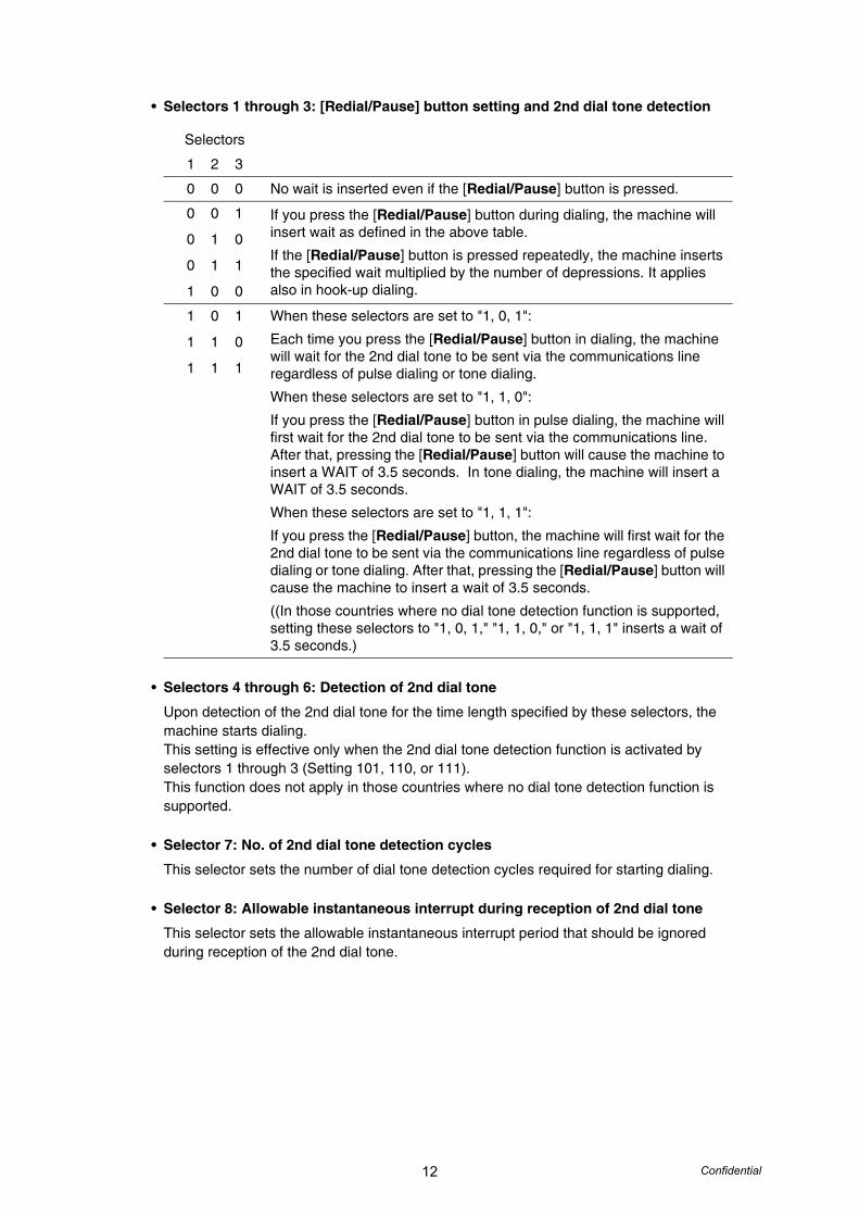
• Selectors 1 through 3: [Redial/Pause] button setting and 2nd dial tone detection
• Selectors 4 through 6: Detection of 2nd dial tone
Upon detection of the 2nd dial tone for the time length specified by these selectors, the machine starts dialing.This setting is effective only when the 2nd dial tone detection function is activated by selectors 1 through 3 (Setting 101, 110, or 111).This function does not apply in those countries where no dial tone detection function is supported.
• Selector 7: No. of 2nd dial tone detection cycles
This selector sets the number of dial tone detection cycles required for starting dialing.
• Selector 8: Allowable instantaneous interrupt during reception of 2nd dial tone
This selector sets the allowable instantaneous interrupt period that should be ignored during reception of the 2nd dial tone.
Selectors
1 2 3
0 0 0 No wait is inserted even if the [Redial/Pause] button is pressed.
0 0 1
0 1 0
0 1 1
1 0 0
If you press the [Redial/Pause] button during dialing, the machine will insert wait as defined in the above table.
If the [Redial/Pause] button is pressed repeatedly, the machine inserts the specified wait multiplied by the number of depressions. It applies also in hook-up dialing.
1 0 1
1 1 0
1 1 1
When these selectors are set to "1, 0, 1":
Each time you press the [Redial/Pause] button in dialing, the machine will wait for the 2nd dial tone to be sent via the communications line regardless of pulse dialing or tone dialing.
When these selectors are set to "1, 1, 0":
If you press the [Redial/Pause] button in pulse dialing, the machine will first wait for the 2nd dial tone to be sent via the communications line. After that, pressing the [Redial/Pause] button will cause the machine to insert a WAIT of 3.5 seconds. In tone dialing, the machine will insert a WAIT of 3.5 seconds.
When these selectors are set to "1, 1, 1":
If you press the [Redial/Pause] button, the machine will first wait for the 2nd dial tone to be sent via the communications line regardless of pulse dialing or tone dialing. After that, pressing the [Redial/Pause] button will cause the machine to insert a wait of 3.5 seconds.
((In those countries where no dial tone detection function is supported, setting these selectors to "1, 0, 1," "1, 1, 0," or "1, 1, 1" inserts a wait of 3.5 seconds.)
13 Confidential
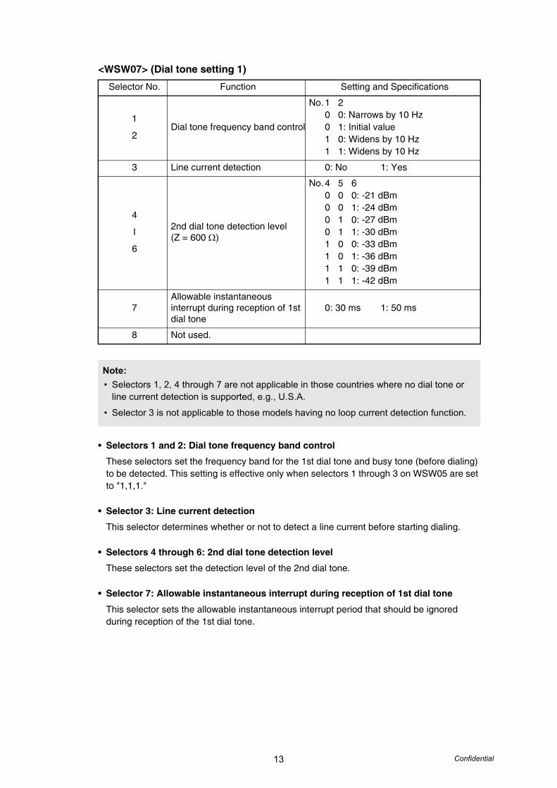
<WSW07> (Dial tone setting 1)
• Selectors 1 and 2: Dial tone frequency band control
These selectors set the frequency band for the 1st dial tone and busy tone (before dialing) to be detected. This setting is effective only when selectors 1 through 3 on WSW05 are set to "1,1,1."
• Selector 3: Line current detection
This selector determines whether or not to detect a line current before starting dialing.
• Selectors 4 through 6: 2nd dial tone detection level
These selectors set the detection level of the 2nd dial tone.
• Selector 7: Allowable instantaneous interrupt during reception of 1st dial tone
This selector sets the allowable instantaneous interrupt period that should be ignored during reception of the 1st dial tone.
Selector No. Function Setting and Specifications
1
2Dial tone frequency band control
No. 1 20 0: Narrows by 10 Hz0 1: Initial value1 0: Widens by 10 Hz1 1: Widens by 10 Hz
3 Line current detection 0: No 1: Yes
4
I
6
2nd dial tone detection level(Z = 600 Ω)
No. 4 5 60 0 0: -21 dBm0 0 1: -24 dBm0 1 0: -27 dBm0 1 1: -30 dBm1 0 0: -33 dBm1 0 1: -36 dBm1 1 0: -39 dBm1 1 1: -42 dBm
7Allowable instantaneous interrupt during reception of 1st dial tone
0: 30 ms 1: 50 ms
8 Not used.
Note:• Selectors 1, 2, 4 through 7 are not applicable in those countries where no dial tone or
line current detection is supported, e.g., U.S.A.
• Selector 3 is not applicable to those models having no loop current detection function.
14 Confidential
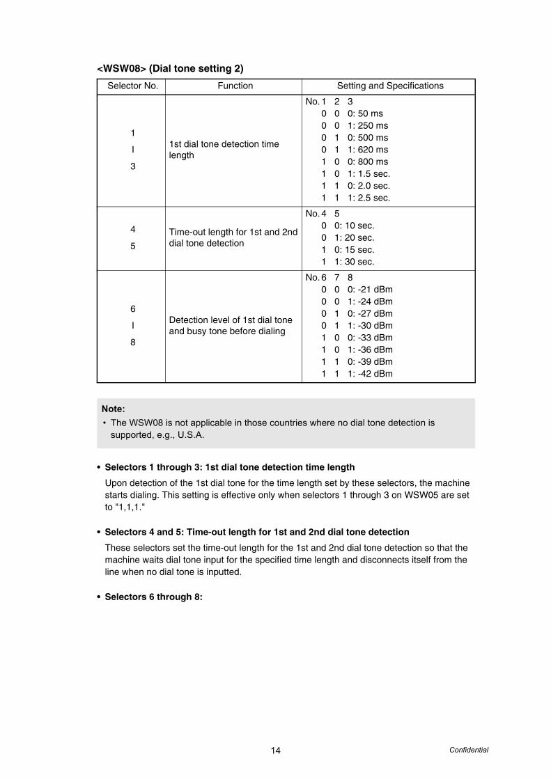
<WSW08> (Dial tone setting 2)
• Selectors 1 through 3: 1st dial tone detection time length
Upon detection of the 1st dial tone for the time length set by these selectors, the machine starts dialing. This setting is effective only when selectors 1 through 3 on WSW05 are set to "1,1,1."
• Selectors 4 and 5: Time-out length for 1st and 2nd dial tone detection
These selectors set the time-out length for the 1st and 2nd dial tone detection so that the machine waits dial tone input for the specified time length and disconnects itself from the line when no dial tone is inputted.
• Selectors 6 through 8:
Selector No. Function Setting and Specifications
1
I
3
1st dial tone detection time length
No. 1 2 30 0 0: 50 ms0 0 1: 250 ms0 1 0: 500 ms0 1 1: 620 ms1 0 0: 800 ms1 0 1: 1.5 sec.1 1 0: 2.0 sec.1 1 1: 2.5 sec.
4
5Time-out length for 1st and 2nd dial tone detection
No. 4 50 0: 10 sec.0 1: 20 sec.1 0: 15 sec.1 1: 30 sec.
6
I
8
Detection level of 1st dial tone and busy tone before dialing
No. 6 7 80 0 0: -21 dBm0 0 1: -24 dBm0 1 0: -27 dBm0 1 1: -30 dBm1 0 0: -33 dBm1 0 1: -36 dBm1 1 0: -39 dBm1 1 1: -42 dBm
Note:• The WSW08 is not applicable in those countries where no dial tone detection is
supported, e.g., U.S.A.

15 Confidential
<WSW09> (Protocol definition 1)
• Selector 1: Frame length selection
Usually a single frame consists of 256 octets (1 octet = 8 bits). For communications lines with higher bit error rate, however, set selector 1 to "1" so that the machine can divide a message into 64-octet frames.Remarks: The error correction mode (ECM) is a facsimile transmission manner in which
the machine divides a message into frames for transmission so that if any data error occurs on the transmission line, the machine retransmits only those frames containing the error data.
• Selector 2: Use of non-standard commands
If this selector is set to "0," the machine can use non-standard commands (the machine's native-mode commands, e.g., NSF, NSC, and NSS) for communications. If it is set to "1," the machine will use standard commands only.
• Selectors 3 and 4: No. of retries
These selectors set the number of retries in each specified modem transmission speed.
• Selector 5: T5 timer
This selector sets the time length for the T5 timer.
• Selector 6: T1 timer
This selector sets the time length for the T1 timer.
• Selectors 7 and 8: Timeout for response from the called station in automatic sending mode
If the machine (calling station) receives no response (no G3 command) from the called terminal in automatic sending mode for the period specified by these selectors, it disconnects the line.
Selector No. Function Setting and Specifications
1 Frame length selection 0: 256 octets 1: 64 octets
2 Use of non-standard commands 0: Allowed 1: Prohibited
3
4No. of retries
No. 3 40 0: 4 times0 1: 3 times1 0: 2 times1 1: 1 times
5 T5 timer 0: 300 sec. 1: 60 sec.
6 T1 timer 0: 35 sec. 1: 40 sec.
7
8
Timeout for response from the called station in automatic sending mode
No. 7 80 0: 55 sec. (in U.S.A., Canadian,
Chile, Brazil and South Africa models)
60 sec. (in other models)0 1: 140 sec.1 0: 90 sec.1 1: 35 sec.
Note:• Selectors 1 through 5 are not applicable in those models which do not support ECM.

16 Confidential
<WSW10> (Protocol definition 2)
• Selector 1: Switching of DPS, following the CML ON/OFF
Setting this selector to "1" automatically switches DPS following the CML ON/OFF operation.
• Selector 2: Time length from transmission of the last dial digit to CML ON
This selector sets the time length from when the machine transmits the last dial digit until the CML relay comes on.
• Selector 3: Time length from CML ON to CNG transmission
This selector sets the time length until the machine transmits a CNG after it turns on the CML relay.
• Selector 4: Time length from CML ON to CED transmission
This selector sets the time length until the machine transmits a CED after it turns on the CML relay. This setting does not apply to switching between facsimile and telephone.
• Selectors 5 and 6: No. of training retries
These selectors set the number of training retries to be repeated before automatic fallback.
• Selectors 7 and 8: Encoding system (Compression)
This selector determines whether or not to allow the use of the MR/MMR coding system.
Selector No. Function Setting and Specifications
1 DPS switching interfacing with CML 0: No 1: Yes
2 Time length from transmission of the last dial digit to CML ON 0: 100 ms 1: 50 ms
3 Time length from CML ON to CNG transmission 0: 2 sec. 1: 4 sec.
4Time length from CML ON to CED transmission (except for facsimile-to-telephone switching)
0: 0.5 sec. 1: 2 sec.
5
6No. of training retries
No. 5 60 0: 1 time0 1: 2 times1 0: 3 times1 1: 4 times
7 Encoding system(Compression)
MR 0: Allowed 1: Not allowed
8 MMR 0: Allowed 1: Not allowed
17 Confidential
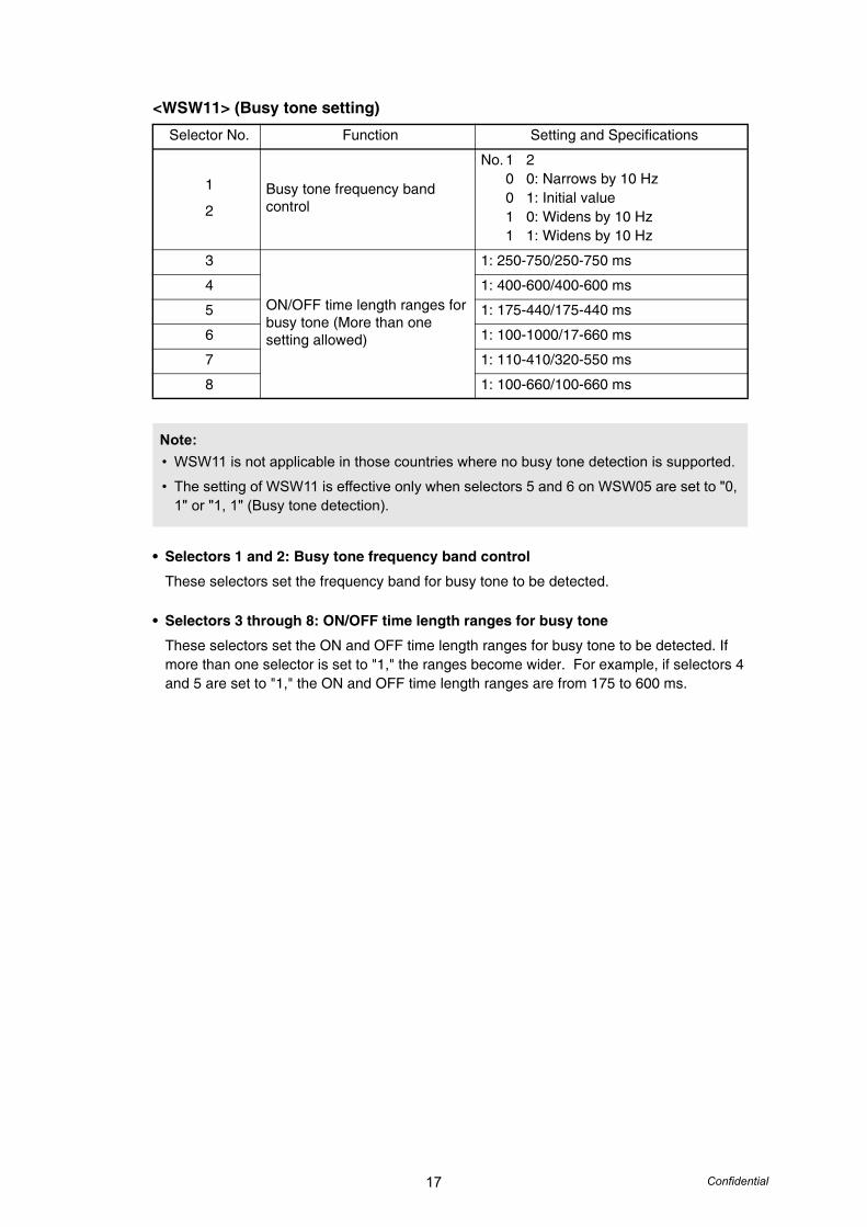
<WSW11> (Busy tone setting)
• Selectors 1 and 2: Busy tone frequency band control
These selectors set the frequency band for busy tone to be detected.
• Selectors 3 through 8: ON/OFF time length ranges for busy tone
These selectors set the ON and OFF time length ranges for busy tone to be detected. If more than one selector is set to "1," the ranges become wider. For example, if selectors 4 and 5 are set to "1," the ON and OFF time length ranges are from 175 to 600 ms.
Selector No. Function Setting and Specifications
1
2Busy tone frequency band control
No. 1 20 0: Narrows by 10 Hz0 1: Initial value1 0: Widens by 10 Hz1 1: Widens by 10 Hz
3
ON/OFF time length ranges for busy tone (More than one setting allowed)
1: 250-750/250-750 ms
4 1: 400-600/400-600 ms
5 1: 175-440/175-440 ms
6 1: 100-1000/17-660 ms
7 1: 110-410/320-550 ms
8 1: 100-660/100-660 ms
Note:• WSW11 is not applicable in those countries where no busy tone detection is supported.
• The setting of WSW11 is effective only when selectors 5 and 6 on WSW05 are set to "0, 1" or "1, 1" (Busy tone detection).
18 Confidential
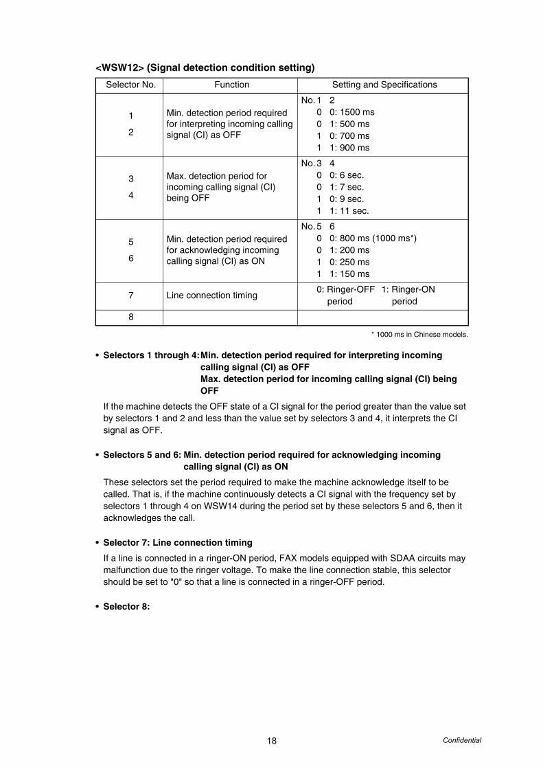
<WSW12> (Signal detection condition setting)
* 1000 ms in Chinese models.
• Selectors 1 through 4:Min. detection period required for interpreting incoming calling signal (CI) as OFFMax. detection period for incoming calling signal (CI) being OFF
If the machine detects the OFF state of a CI signal for the period greater than the value set by selectors 1 and 2 and less than the value set by selectors 3 and 4, it interprets the CI signal as OFF.
• Selectors 5 and 6: Min. detection period required for acknowledging incoming calling signal (CI) as ON
These selectors set the period required to make the machine acknowledge itself to be called. That is, if the machine continuously detects a CI signal with the frequency set by selectors 1 through 4 on WSW14 during the period set by these selectors 5 and 6, then it acknowledges the call.
• Selector 7: Line connection timing
If a line is connected in a ringer-ON period, FAX models equipped with SDAA circuits may malfunction due to the ringer voltage. To make the line connection stable, this selector should be set to "0" so that a line is connected in a ringer-OFF period.
• Selector 8:
Selector No. Function Setting and Specifications
1
2
Min. detection period required for interpreting incoming calling signal (CI) as OFF
No. 1 20 0: 1500 ms0 1: 500 ms1 0: 700 ms1 1: 900 ms
3
4
Max. detection period for incoming calling signal (CI) being OFF
No. 3 40 0: 6 sec.0 1: 7 sec.1 0: 9 sec.1 1: 11 sec.
5
6
Min. detection period required for acknowledging incoming calling signal (CI) as ON
No. 5 60 0: 800 ms (1000 ms*)0 1: 200 ms1 0: 250 ms1 1: 150 ms
7 Line connection timing0: Ringer-OFF 1: Ringer-ON period period
8
19 Confidential
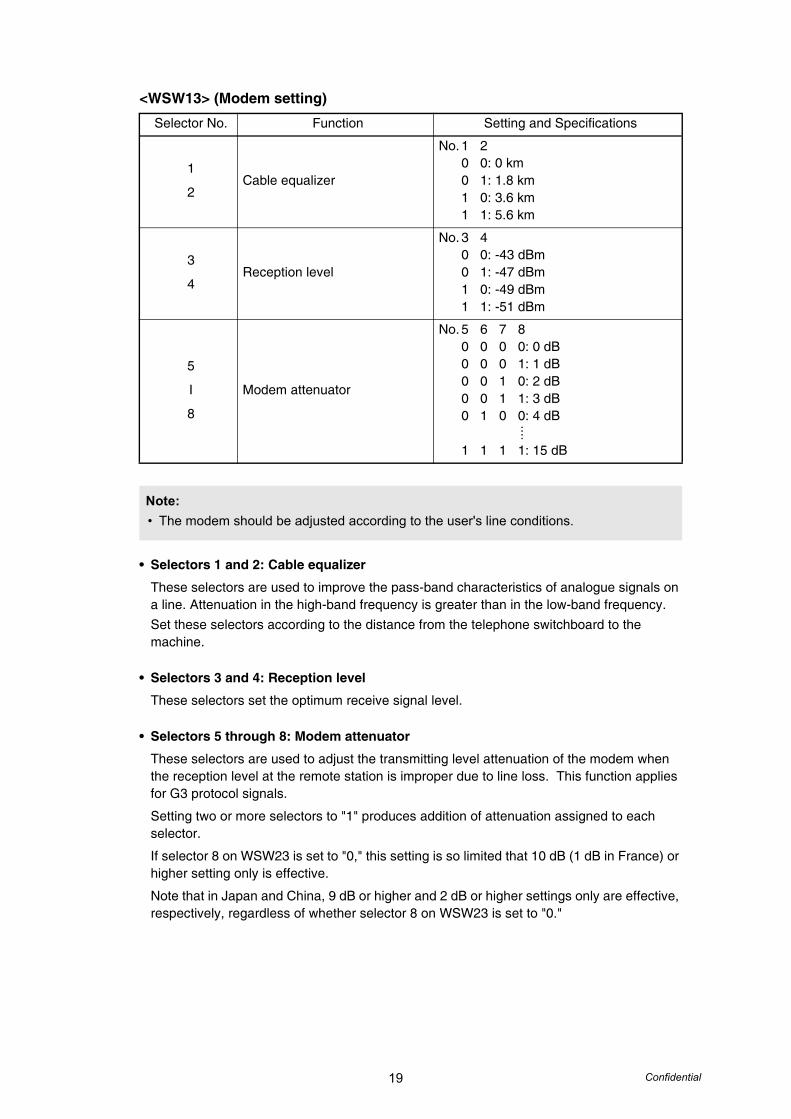
<WSW13> (Modem setting)
• Selectors 1 and 2: Cable equalizer
These selectors are used to improve the pass-band characteristics of analogue signals on a line. Attenuation in the high-band frequency is greater than in the low-band frequency.Set these selectors according to the distance from the telephone switchboard to the machine.
• Selectors 3 and 4: Reception level
These selectors set the optimum receive signal level.
• Selectors 5 through 8: Modem attenuator
These selectors are used to adjust the transmitting level attenuation of the modem when the reception level at the remote station is improper due to line loss. This function applies for G3 protocol signals.
Setting two or more selectors to "1" produces addition of attenuation assigned to each selector.
If selector 8 on WSW23 is set to "0," this setting is so limited that 10 dB (1 dB in France) or higher setting only is effective.
Note that in Japan and China, 9 dB or higher and 2 dB or higher settings only are effective, respectively, regardless of whether selector 8 on WSW23 is set to "0."
Selector No. Function Setting and Specifications
1
2Cable equalizer
No. 1 20 0: 0 km0 1: 1.8 km1 0: 3.6 km1 1: 5.6 km
3
4Reception level
No. 3 40 0: -43 dBm0 1: -47 dBm1 0: -49 dBm1 1: -51 dBm
5
I
8
Modem attenuator
No. 5 6 7 80 0 0 0: 0 dB0 0 0 1: 1 dB0 0 1 0: 2 dB0 0 1 1: 3 dB0 1 0 0: 4 dB
1 1 1 1: 15 dB
Note:• The modem should be adjusted according to the user's line conditions.
....
20 Confidential
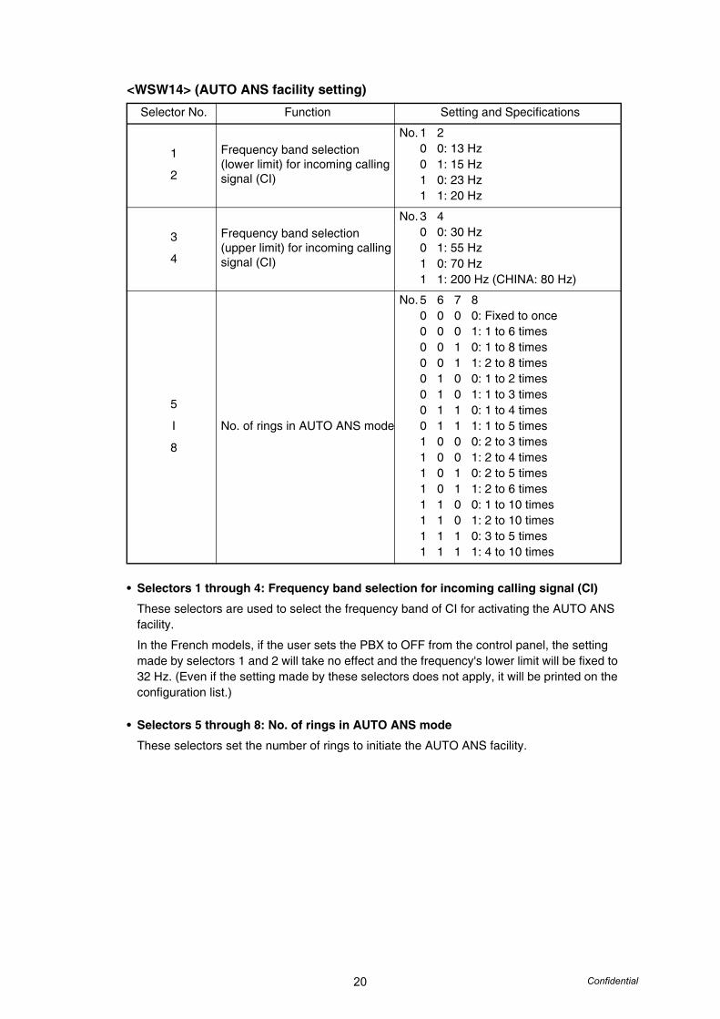
<WSW14> (AUTO ANS facility setting)
• Selectors 1 through 4: Frequency band selection for incoming calling signal (CI)
These selectors are used to select the frequency band of CI for activating the AUTO ANS facility.
In the French models, if the user sets the PBX to OFF from the control panel, the setting made by selectors 1 and 2 will take no effect and the frequency's lower limit will be fixed to 32 Hz. (Even if the setting made by these selectors does not apply, it will be printed on the configuration list.)
• Selectors 5 through 8: No. of rings in AUTO ANS mode
These selectors set the number of rings to initiate the AUTO ANS facility.
Selector No. Function Setting and Specifications
1
2
Frequency band selection (lower limit) for incoming calling signal (CI)
No. 1 20 0: 13 Hz0 1: 15 Hz1 0: 23 Hz1 1: 20 Hz
3
4
Frequency band selection (upper limit) for incoming calling signal (CI)
No. 3 40 0: 30 Hz0 1: 55 Hz1 0: 70 Hz1 1: 200 Hz (CHINA: 80 Hz)
5
I
8
No. of rings in AUTO ANS mode
No. 5 6 7 80 0 0 0: Fixed to once0 0 0 1: 1 to 6 times0 0 1 0: 1 to 8 times0 0 1 1: 2 to 8 times0 1 0 0: 1 to 2 times0 1 0 1: 1 to 3 times0 1 1 0: 1 to 4 times0 1 1 1: 1 to 5 times1 0 0 0: 2 to 3 times1 0 0 1: 2 to 4 times1 0 1 0: 2 to 5 times1 0 1 1: 2 to 6 times1 1 0 0: 1 to 10 times1 1 0 1: 2 to 10 times1 1 1 0: 3 to 5 times1 1 1 1: 4 to 10 times
21 Confidential
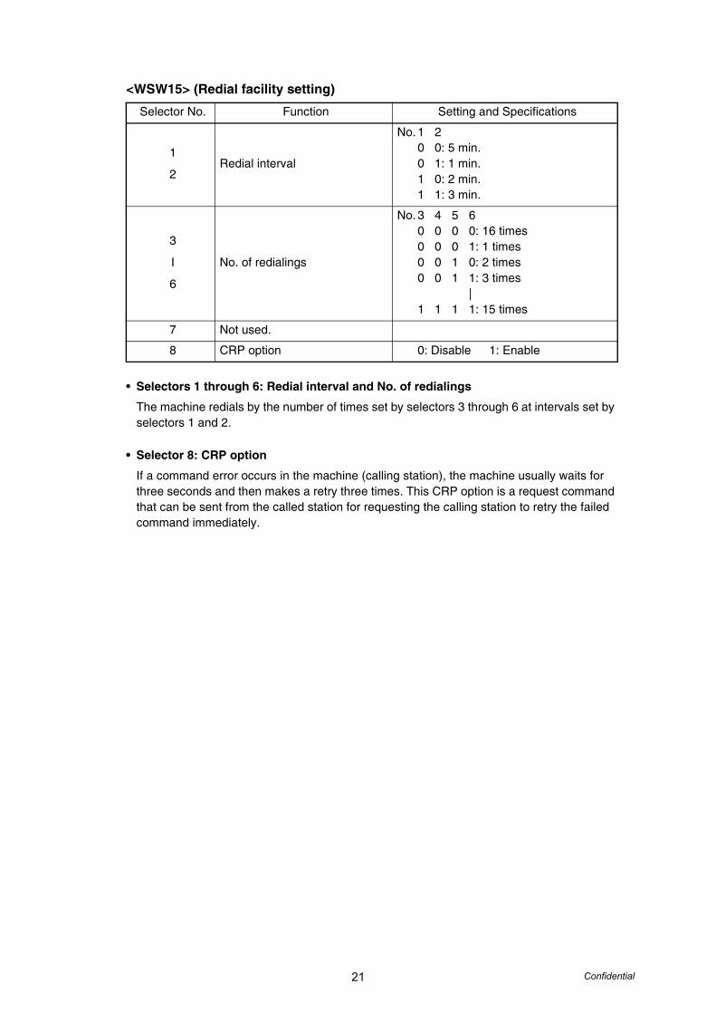
<WSW15> (Redial facility setting)
• Selectors 1 through 6: Redial interval and No. of redialings
The machine redials by the number of times set by selectors 3 through 6 at intervals set by selectors 1 and 2.
• Selector 8: CRP option
If a command error occurs in the machine (calling station), the machine usually waits for three seconds and then makes a retry three times. This CRP option is a request command that can be sent from the called station for requesting the calling station to retry the failed command immediately.
Selector No. Function Setting and Specifications
1
2Redial interval
No. 1 20 0: 5 min.0 1: 1 min.1 0: 2 min.1 1: 3 min.
3
I
6
No. of redialings
No. 3 4 5 60 0 0 0: 16 times0 0 0 1: 1 times0 0 1 0: 2 times0 0 1 1: 3 times
|1 1 1 1: 15 times
7 Not used.
8 CRP option 0: Disable 1: Enable
22 Confidential
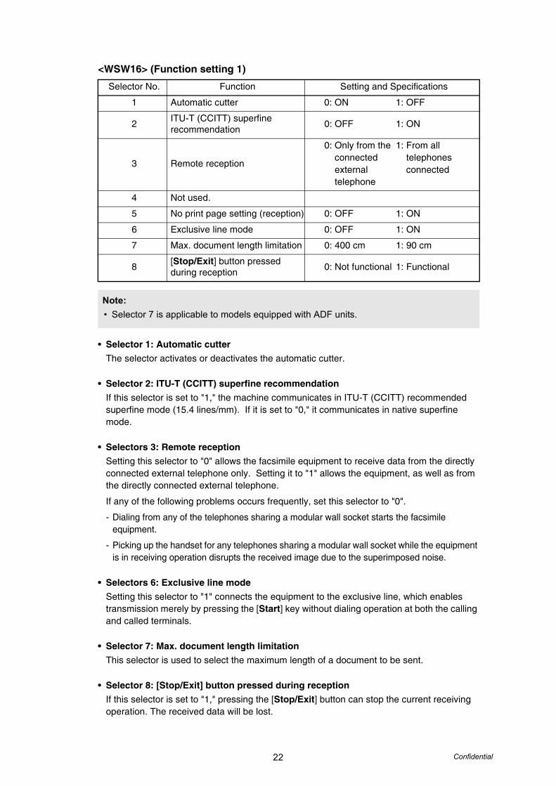
<WSW16> (Function setting 1)
• Selector 1: Automatic cutterThe selector activates or deactivates the automatic cutter.
• Selector 2: ITU-T (CCITT) superfine recommendationIf this selector is set to "1," the machine communicates in ITU-T (CCITT) recommended superfine mode (15.4 lines/mm). If it is set to "0," it communicates in native superfine mode.
• Selectors 3: Remote receptionSetting this selector to "0" allows the facsimile equipment to receive data from the directly connected external telephone only. Setting it to "1" allows the equipment, as well as from the directly connected external telephone.
If any of the following problems occurs frequently, set this selector to "0".
- Dialing from any of the telephones sharing a modular wall socket starts the facsimile equipment.
- Picking up the handset for any telephones sharing a modular wall socket while the equipment is in receiving operation disrupts the received image due to the superimposed noise.
• Selectors 6: Exclusive line modeSetting this selector to "1" connects the equipment to the exclusive line, which enables transmission merely by pressing the [Start] key without dialing operation at both the calling and called terminals.
• Selector 7: Max. document length limitationThis selector is used to select the maximum length of a document to be sent.
• Selector 8: [Stop/Exit] button pressed during receptionIf this selector is set to "1," pressing the [Stop/Exit] button can stop the current receiving operation. The received data will be lost.
Selector No. Function Setting and Specifications
1 Automatic cutter 0: ON 1: OFF
2 ITU-T (CCITT) superfine recommendation 0: OFF 1: ON
3 Remote reception
0: Only from the 1: From all connected telephones external connected telephone
4 Not used.
5 No print page setting (reception) 0: OFF 1: ON
6 Exclusive line mode 0: OFF 1: ON
7 Max. document length limitation 0: 400 cm 1: 90 cm
8 [Stop/Exit] button pressed during reception 0: Not functional 1: Functional
Note:• Selector 7 is applicable to models equipped with ADF units.
23 Confidential
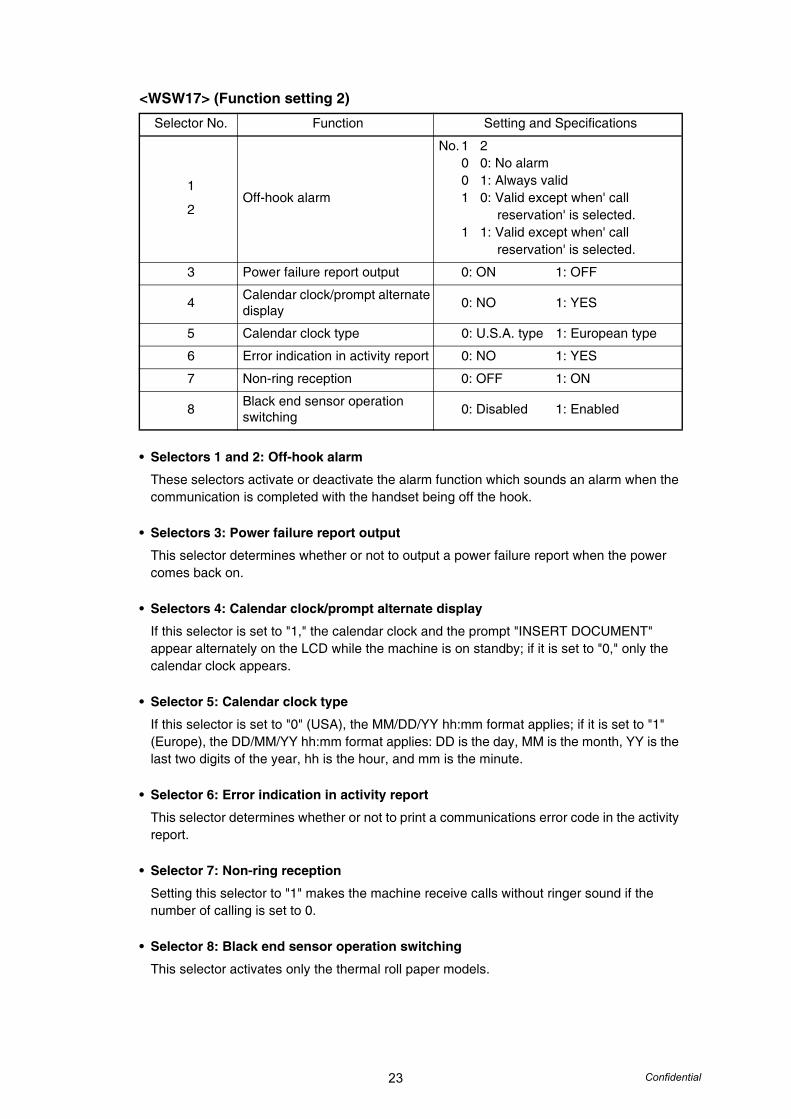
<WSW17> (Function setting 2)
• Selectors 1 and 2: Off-hook alarm
These selectors activate or deactivate the alarm function which sounds an alarm when the communication is completed with the handset being off the hook.
• Selectors 3: Power failure report output
This selector determines whether or not to output a power failure report when the power comes back on.
• Selectors 4: Calendar clock/prompt alternate display
If this selector is set to "1," the calendar clock and the prompt "INSERT DOCUMENT" appear alternately on the LCD while the machine is on standby; if it is set to "0," only the calendar clock appears.
• Selector 5: Calendar clock type
If this selector is set to "0" (USA), the MM/DD/YY hh:mm format applies; if it is set to "1" (Europe), the DD/MM/YY hh:mm format applies: DD is the day, MM is the month, YY is the last two digits of the year, hh is the hour, and mm is the minute.
• Selector 6: Error indication in activity report
This selector determines whether or not to print a communications error code in the activity report.
• Selector 7: Non-ring reception
Setting this selector to "1" makes the machine receive calls without ringer sound if the number of calling is set to 0.
• Selector 8: Black end sensor operation switching
This selector activates only the thermal roll paper models.
Selector No. Function Setting and Specifications
1
2Off-hook alarm
No. 1 20 0: No alarm0 1: Always valid1 0: Valid except when' call
reservation' is selected.1 1: Valid except when' call
reservation' is selected.
3 Power failure report output 0: ON 1: OFF
4 Calendar clock/prompt alternate display 0: NO 1: YES
5 Calendar clock type 0: U.S.A. type 1: European type
6 Error indication in activity report 0: NO 1: YES
7 Non-ring reception 0: OFF 1: ON
8 Black end sensor operation switching 0: Disabled 1: Enabled
24 Confidential
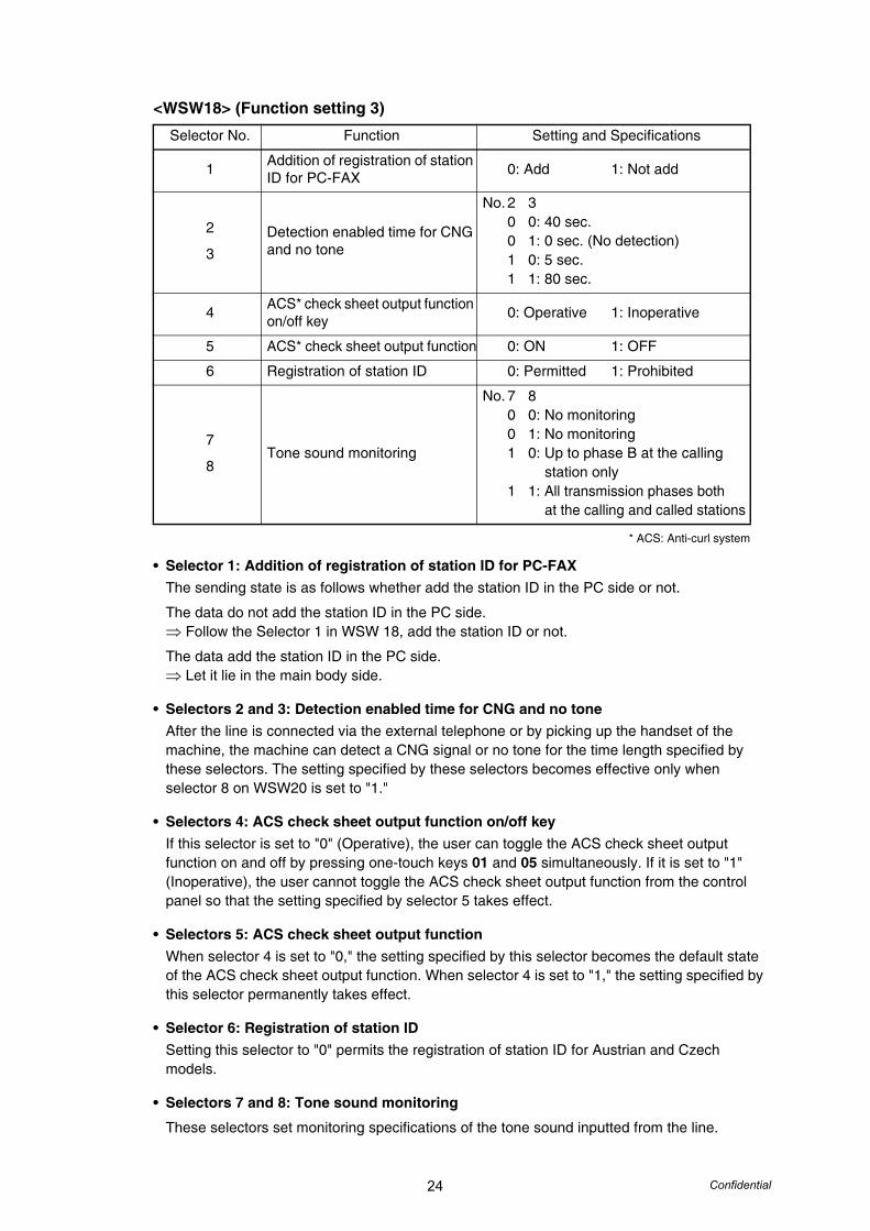
<WSW18> (Function setting 3)
* ACS: Anti-curl system
• Selector 1: Addition of registration of station ID for PC-FAXThe sending state is as follows whether add the station ID in the PC side or not.
The data do not add the station ID in the PC side.⇒ Follow the Selector 1 in WSW 18, add the station ID or not.
The data add the station ID in the PC side.⇒ Let it lie in the main body side.
• Selectors 2 and 3: Detection enabled time for CNG and no toneAfter the line is connected via the external telephone or by picking up the handset of the machine, the machine can detect a CNG signal or no tone for the time length specified by these selectors. The setting specified by these selectors becomes effective only when selector 8 on WSW20 is set to "1."
• Selectors 4: ACS check sheet output function on/off keyIf this selector is set to "0" (Operative), the user can toggle the ACS check sheet output function on and off by pressing one-touch keys 01 and 05 simultaneously. If it is set to "1" (Inoperative), the user cannot toggle the ACS check sheet output function from the control panel so that the setting specified by selector 5 takes effect.
• Selectors 5: ACS check sheet output functionWhen selector 4 is set to "0," the setting specified by this selector becomes the default state of the ACS check sheet output function. When selector 4 is set to "1," the setting specified by this selector permanently takes effect.
• Selector 6: Registration of station IDSetting this selector to "0" permits the registration of station ID for Austrian and Czech models.
• Selectors 7 and 8: Tone sound monitoring
These selectors set monitoring specifications of the tone sound inputted from the line.
Selector No. Function Setting and Specifications
1 Addition of registration of station ID for PC-FAX 0: Add 1: Not add
2
3Detection enabled time for CNG and no tone
No. 2 30 0: 40 sec.0 1: 0 sec. (No detection)1 0: 5 sec.1 1: 80 sec.
4 ACS* check sheet output function on/off key 0: Operative 1: Inoperative
5 ACS* check sheet output function 0: ON 1: OFF
6 Registration of station ID 0: Permitted 1: Prohibited
7
8Tone sound monitoring
No. 7 80 0: No monitoring0 1: No monitoring1 0: Up to phase B at the calling
station only1 1: All transmission phases both
at the calling and called stations
25 Confidential
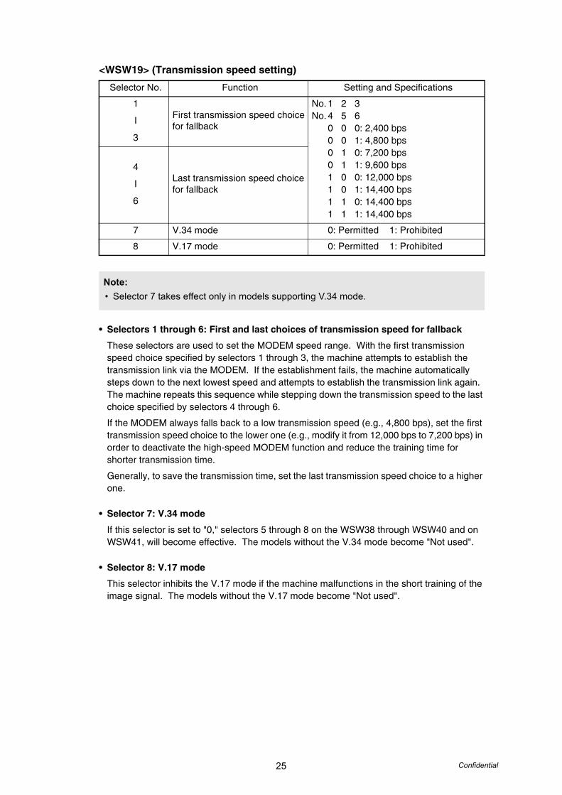
<WSW19> (Transmission speed setting)
• Selectors 1 through 6: First and last choices of transmission speed for fallback
These selectors are used to set the MODEM speed range. With the first transmission speed choice specified by selectors 1 through 3, the machine attempts to establish the transmission link via the MODEM. If the establishment fails, the machine automatically steps down to the next lowest speed and attempts to establish the transmission link again. The machine repeats this sequence while stepping down the transmission speed to the last choice specified by selectors 4 through 6.
If the MODEM always falls back to a low transmission speed (e.g., 4,800 bps), set the first transmission speed choice to the lower one (e.g., modify it from 12,000 bps to 7,200 bps) in order to deactivate the high-speed MODEM function and reduce the training time for shorter transmission time.
Generally, to save the transmission time, set the last transmission speed choice to a higher one.
• Selector 7: V.34 mode
If this selector is set to "0," selectors 5 through 8 on the WSW38 through WSW40 and on WSW41, will become effective. The models without the V.34 mode become "Not used".
• Selector 8: V.17 mode
This selector inhibits the V.17 mode if the machine malfunctions in the short training of the image signal. The models without the V.17 mode become "Not used".
Selector No. Function Setting and Specifications
1
I
3
First transmission speed choice for fallback
No. 1 2 3No. 4 5 6
0 0 0: 2,400 bps0 0 1: 4,800 bps0 1 0: 7,200 bps0 1 1: 9,600 bps1 0 0: 12,000 bps1 0 1: 14,400 bps1 1 0: 14,400 bps1 1 1: 14,400 bps
4
I
6
Last transmission speed choice for fallback
7 V.34 mode 0: Permitted 1: Prohibited
8 V.17 mode 0: Permitted 1: Prohibited
Note:• Selector 7 takes effect only in models supporting V.34 mode.
26 Confidential
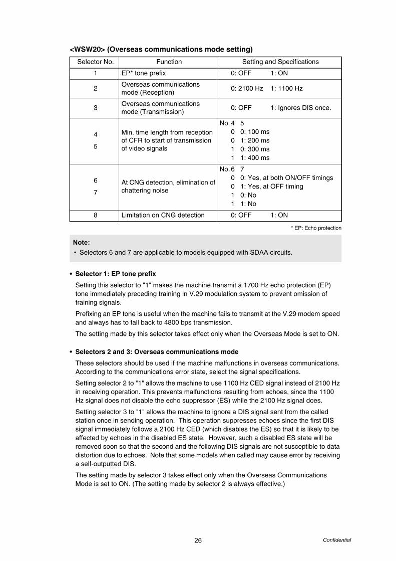
<WSW20> (Overseas communications mode setting)
* EP: Echo protection
• Selector 1: EP tone prefix
Setting this selector to "1" makes the machine transmit a 1700 Hz echo protection (EP) tone immediately preceding training in V.29 modulation system to prevent omission of training signals.
Prefixing an EP tone is useful when the machine fails to transmit at the V.29 modem speed and always has to fall back to 4800 bps transmission.
The setting made by this selector takes effect only when the Overseas Mode is set to ON.
• Selectors 2 and 3: Overseas communications mode
These selectors should be used if the machine malfunctions in overseas communications. According to the communications error state, select the signal specifications.
Setting selector 2 to "1" allows the machine to use 1100 Hz CED signal instead of 2100 Hz in receiving operation. This prevents malfunctions resulting from echoes, since the 1100 Hz signal does not disable the echo suppressor (ES) while the 2100 Hz signal does.
Setting selector 3 to "1" allows the machine to ignore a DIS signal sent from the called station once in sending operation. This operation suppresses echoes since the first DIS signal immediately follows a 2100 Hz CED (which disables the ES) so that it is likely to be affected by echoes in the disabled ES state. However, such a disabled ES state will be removed soon so that the second and the following DIS signals are not susceptible to data distortion due to echoes. Note that some models when called may cause error by receiving a self-outputted DIS.
The setting made by selector 3 takes effect only when the Overseas Communications Mode is set to ON. (The setting made by selector 2 is always effective.)
Selector No. Function Setting and Specifications
1 EP* tone prefix 0: OFF 1: ON
2 Overseas communications mode (Reception) 0: 2100 Hz 1: 1100 Hz
3 Overseas communications mode (Transmission) 0: OFF 1: Ignores DIS once.
4
5
Min. time length from reception of CFR to start of transmission of video signals
No. 4 50 0: 100 ms0 1: 200 ms1 0: 300 ms1 1: 400 ms
6
7At CNG detection, elimination of chattering noise
No. 6 70 0: Yes, at both ON/OFF timings0 1: Yes, at OFF timing1 0: No1 1: No
8 Limitation on CNG detection 0: OFF 1: ON
Note:• Selectors 6 and 7 are applicable to models equipped with SDAA circuits.
27 Confidential
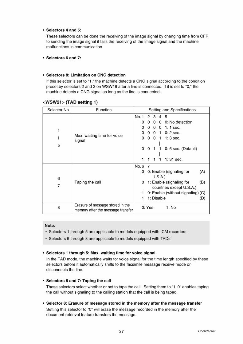
• Selectors 4 and 5: These selectors can be done the receiving of the image signal by changing time from CFR to sending the image signal if fails the receiving of the image signal and the machine malfunctions in communication.
• Selectors 6 and 7:
• Selectors 8: Limitation on CNG detectionIf this selector is set to "1," the machine detects a CNG signal according to the condition preset by selectors 2 and 3 on WSW18 after a line is connected. If it is set to "0," the machine detects a CNG signal as long as the line is connected.
<WSW21> (TAD setting 1)
• Selectors 1 through 5: Max. waiting time for voice signalIn the TAD mode, the machine waits for voice signal for the time length specified by these selectors before it automatically shifts to the facsimile message receive mode or disconnects the line.
• Selectors 6 and 7: Taping the callThese selectors select whether or not to tape the call. Setting them to "1, 0" enables taping the call without signaling to the calling station that the call is being taped.
• Selector 8: Erasure of message stored in the memory after the message transferSetting this selector to "0" will erase the message recorded in the memory after the document retrieval feature transfers the message.
Selector No. Function Setting and Specifications
1
I
5
Max. waiting time for voice signal
No. 1 2 3 4 50 0 0 0 0: No detection0 0 0 0 1: 1 sec.0 0 0 1 0: 2 sec.0 0 0 1 1: 3 sec.
|0 0 1 1 0: 6 sec. (Default)
|1 1 1 1 1: 31 sec.
6
7Taping the call
No. 6 70 0: Enable (signaling for (A) U.S.A.)0 1: Enable (signaling for (B) countries except U.S.A.)1 0: Enable (without signaling) (C)1 1: Disable (D)
8 Erasure of message stored in the memory after the message transfer 0: Yes 1: No
Note:• Selectors 1 through 5 are applicable to models equipped with ICM recorders.
• Selectors 6 through 8 are applicable to models equipped with TADs.
28 Confidential
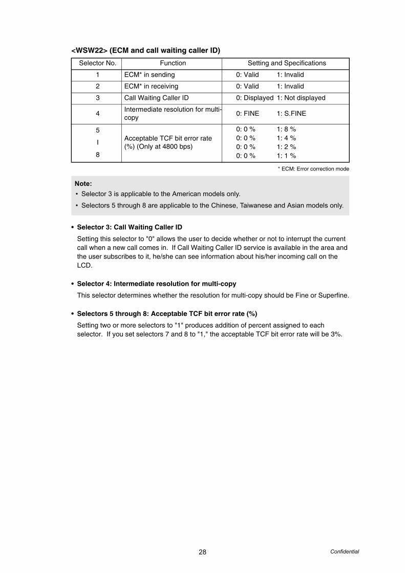
<WSW22> (ECM and call waiting caller ID)
* ECM: Error correction mode
• Selector 3: Call Waiting Caller ID
Setting this selector to "0" allows the user to decide whether or not to interrupt the current call when a new call comes in. If Call Waiting Caller ID service is available in the area and the user subscribes to it, he/she can see information about his/her incoming call on the LCD.
• Selector 4: Intermediate resolution for multi-copy
This selector determines whether the resolution for multi-copy should be Fine or Superfine.
• Selectors 5 through 8: Acceptable TCF bit error rate (%)
Setting two or more selectors to "1" produces addition of percent assigned to each selector. If you set selectors 7 and 8 to "1," the acceptable TCF bit error rate will be 3%.
Selector No. Function Setting and Specifications
1 ECM* in sending 0: Valid 1: Invalid
2 ECM* in receiving 0: Valid 1: Invalid
3 Call Waiting Caller ID 0: Displayed 1: Not displayed
4 Intermediate resolution for multi-copy 0: FINE 1: S.FINE
5
I
8
Acceptable TCF bit error rate (%) (Only at 4800 bps)
0: 0 % 1: 8 %0: 0 % 1: 4 %0: 0 % 1: 2 %0: 0 % 1: 1 %
Note:• Selector 3 is applicable to the American models only.
• Selectors 5 through 8 are applicable to the Chinese, Taiwanese and Asian models only.

29 Confidential
<WSW23> (Communications setting)
• Selector 1: Starting point of training check (TCF)
At the training phase of receiving operation, the called station detects for 1.0 second a training check (TCF) command, a series of zeros which is sent from the calling station for 1.5 seconds to verify training and give the first indication of the acceptability of the line.
This selector sets the starting point from which the called station should start counting those zeros. If this selector is set to "0," the called station starts counting zeros 100 ms after the head of a series of zeros is detected.
If it is set to "1," the called station starts counting zeros upon detection of 10-ms successive zeros 50 ms after the head of a series of zeros is detected. In this case, if the detection of 10-ms successive zeros is too late, the data counting period will become less than 1.0 second, making the called station judge the line condition unacceptable.
• Selectors 2 and 3: Allowable training error rate
The called station checks a series of zeros gathered in training (as described in Selector 1) according to the allowable training error rate set by these selectors. If the called station judges the line condition to be accepted, it responds with CFR; if not, it responds with FTT.
• Selectors 4 and 5: Decoding error rate for transmission of RTN
The machine checks the actual decoding errors and then transmits an RTN according to the decoding error rate (Number of lines containing an error per page ÷ Total number of lines per page) set by these selectors.
• Selectors 6: Issue of RTN at the occurrence of a pagination error
If this selector is set to "0," the machine transmits an RTN when a pagination error occurs due to recording lag relative to receiving.
Selector No. Function Setting and Specifications
1 Starting point of training check (TCF)
0: 0 From the head of a series of zeros1: From any arbitrary point
2
3Allowable training error rate
No. 2 30 0: 0 %0 1: 0.5 %1 0: 1 %1 1: 2 %
4
5Decoding error rate for transmission of RTN
No. 4 50 0: 16 %0 1: 14%1 0: 10 %1 1: 8 %
6 Issue of RTN at the occurrence of a pagination error 0: Yes 1: No
7 Limitation of received resolution at the return from sleep 0: Yes 1: No
8 Limitation of attenuation level 0: Yes 1: No
Note:• Selector 8 is not applicable to the French/Japan/China models.

30 Confidential
• Selectors 7: Limitation of received resolution at the return from sleep
If this selector is set to "Yes," the resolution is set down 1 dpi.
• Selector 8: Limitation of attenuation level
Setting this selector to "0" limits the transmitting level of the modem to -10 dB. This setting has priority over the settings selected by WSW02 (selectors 5 through 8) and WSW13 (selectors 5 through 8).
<WSW24> (TAD setting 2)
• Selectors 1 and 2: Maximum OGM recording time
These selectors set the allowable maximum recording time for an OGM.
• Selectors 3 and 4:Time length from CML ON to start of pseudo ring backtone transmission
These selectors set the length of time from CML-ON up to the start of pseudo ring backtone transmission.
In models with OGM facilities, the settings made by these selectors also apply to the length of time from CML-ON up to the start of OGM transmission.
• Selectors 5 through 8: Attenuator for playback of ICM/OGM to the line
Setting two or more selectors to "1" produces addition of attenuation assigned to each selector.
This setting is not limited by selector 8 on WSW23.
Selector No. Function Setting and Specifications
1
2Maximum OGM recording time
No. 1 20 0: 15 sec.0 1: 20 sec.1 0: 30 sec.1 1: 50 sec.
3
4
Time length from CML ON to start of pseudo ring backtone transmission
No. 3 40 0: 4 sec.0 1: 3 sec.1 0: 2 sec.1 1: 1 sec.
5
I
8
Attenuator for playback of ICM/OGM to the line
0: 0 dB 1: 8 dB0: 0 dB 1: 4 dB0: 0 dB 1: 2 dB0: 0 dB 1: 1 dB
31 Confidential
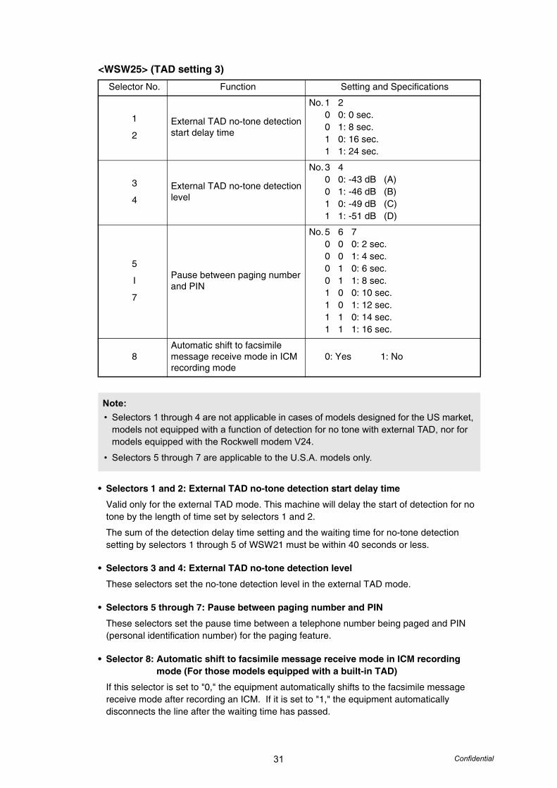
<WSW25> (TAD setting 3)
• Selectors 1 and 2: External TAD no-tone detection start delay time
Valid only for the external TAD mode. This machine will delay the start of detection for no tone by the length of time set by selectors 1 and 2.
The sum of the detection delay time setting and the waiting time for no-tone detection setting by selectors 1 through 5 of WSW21 must be within 40 seconds or less.
• Selectors 3 and 4: External TAD no-tone detection level
These selectors set the no-tone detection level in the external TAD mode.
• Selectors 5 through 7: Pause between paging number and PIN
These selectors set the pause time between a telephone number being paged and PIN (personal identification number) for the paging feature.
• Selector 8: Automatic shift to facsimile message receive mode in ICM recording mode (For those models equipped with a built-in TAD)
If this selector is set to "0," the equipment automatically shifts to the facsimile message receive mode after recording an ICM. If it is set to "1," the equipment automatically disconnects the line after the waiting time has passed.
Selector No. Function Setting and Specifications
1
2External TAD no-tone detection start delay time
No. 1 20 0: 0 sec.0 1: 8 sec.1 0: 16 sec.1 1: 24 sec.
3
4External TAD no-tone detection level
No. 3 40 0: -43 dB (A)0 1: -46 dB (B)1 0: -49 dB (C)1 1: -51 dB (D)
5
I
7
Pause between paging number and PIN
No. 5 6 70 0 0: 2 sec.0 0 1: 4 sec.0 1 0: 6 sec.0 1 1: 8 sec.1 0 0: 10 sec.1 0 1: 12 sec.1 1 0: 14 sec.1 1 1: 16 sec.
8Automatic shift to facsimile message receive mode in ICM recording mode
0: Yes 1: No
Note:• Selectors 1 through 4 are not applicable in cases of models designed for the US market,
models not equipped with a function of detection for no tone with external TAD, nor for models equipped with the Rockwell modem V24.
• Selectors 5 through 7 are applicable to the U.S.A. models only.
32 Confidential
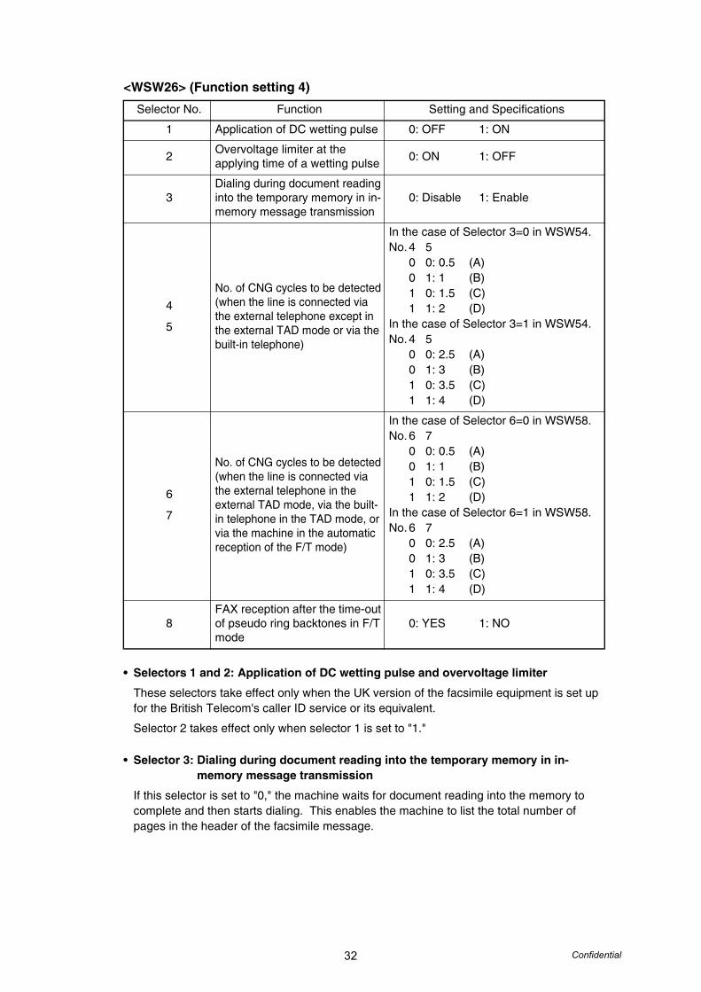
<WSW26> (Function setting 4)
• Selectors 1 and 2: Application of DC wetting pulse and overvoltage limiter
These selectors take effect only when the UK version of the facsimile equipment is set up for the British Telecom's caller ID service or its equivalent.
Selector 2 takes effect only when selector 1 is set to "1."
• Selector 3: Dialing during document reading into the temporary memory in in-memory message transmission
If this selector is set to "0," the machine waits for document reading into the memory to complete and then starts dialing. This enables the machine to list the total number of pages in the header of the facsimile message.
Selector No. Function Setting and Specifications
1 Application of DC wetting pulse 0: OFF 1: ON
2 Overvoltage limiter at the applying time of a wetting pulse 0: ON 1: OFF
3Dialing during document reading into the temporary memory in in-memory message transmission
0: Disable 1: Enable
4
5
No. of CNG cycles to be detected (when the line is connected via the external telephone except in the external TAD mode or via the built-in telephone)
In the case of Selector 3=0 in WSW54.No. 4 5
0 0: 0.5 (A)0 1: 1 (B)1 0: 1.5 (C)1 1: 2 (D)
In the case of Selector 3=1 in WSW54.No. 4 5
0 0: 2.5 (A)0 1: 3 (B)1 0: 3.5 (C)1 1: 4 (D)
6
7
No. of CNG cycles to be detected (when the line is connected via the external telephone in the external TAD mode, via the built-in telephone in the TAD mode, or via the machine in the automatic reception of the F/T mode)
In the case of Selector 6=0 in WSW58.No. 6 7
0 0: 0.5 (A)0 1: 1 (B)1 0: 1.5 (C)1 1: 2 (D)
In the case of Selector 6=1 in WSW58.No. 6 7
0 0: 2.5 (A)0 1: 3 (B)1 0: 3.5 (C)1 1: 4 (D)
8FAX reception after the time-out of pseudo ring backtones in F/T mode
0: YES 1: NO
33 Confidential
• Selectors 4 and 5:No. of CNG cycles to be detected (when the line is connected via the external telephone except in the external TAD mode or via the built-in telephone)
The machine interprets a CNG as an effective signal if it detects the CNG by the number of cycles specified by these selectors when the line is connected via the external telephone except in the external TAD mode or via the built-in telephone.
• Selectors 6 and 7:No. of CNG cycles to be detected (when the line is connected via the external telephone in the external TAD mode, via the built-in telephone in the TAD mode, or via the machine in the automatic reception of the F/T mode)
The machine interprets a CNG as an effective signal if it detects the CNG by the number of cycles specified by these selectors when the line is connected via the external telephone in the external TAD mode, via the built-in telephone in the TAD mode, or via the machine in the automatic reception of the F/T mode.
• Selector 8: FAX reception after the time-out of pseudo ring backtones in F/T mode
If this selector is set to "0," the equipment enters the facsimile receive mode after issuing pseudo ring backtones. If it is set to "1," the equipment disconnects the line after issuing pseudo ring backtones.

34 Confidential
<WSW27> (Function setting 5)
• Selector 1: Definition of programmable key
This selector defines a programmable key as a TEL key or TEL/POLLING key.
Setting this selector to "1" allows the programmable key to function as either a TEL or POLLING key if pressed when the handset is off or on the hook, respectively.
This setting is effective only for those models having a programmable key.
• Selector 2: Ringer OFF setting
This selector determines whether or not the ringer can be set to OFF.
• Selector 3: Automatic playback of OGM when switched to the TAD mode
This selector determines whether or not to automatically play back an OGM the moment the machine switches to the TAD mode.
• Selector 4: Detection of distinctive ringing pattern
If this selector is set to "1," the machine detects only the number of rings; if it is set to "0," the machine detects the number of rings and the ringing time length to compare the detected ringing pattern with the registered distinctive one.
• Selector 5: Automatic erasure of voice alarm
This selector determines whether or not the voice alarm should be erased from the memory after it is issued.
• Selector 6: Recording quality
This selector determines the recording quality for the OGM and ICM. Selecting "1" (High) increases the quality, sacrificing the recording time.
Selector No. Function Setting and Specifications
1 Definition of programmable key 0: TEL key 1: TEL/POLLING key
2 Ringer OFF setting 0: Yes 1: No
3 Automatic playback of OGM when switched to the TAD mode 0: No 1: Yes
4 Detection of distinctive ringing pattern 0: Yes 1: No
5 Automatic erasure of voice alarm 0: Yes 1: No
6 Recording quality 0: Normal 1: High
7 Recording time for high recording quality 0: Short (9.6 kbps) 1: Long (8.8 kbps)
8Suppression of FAX data reception when the recording head is overheated
0: No 1: Yes
Note:• Selectors 4 and 5 are applicable to the U.S.A. models only.
35 Confidential
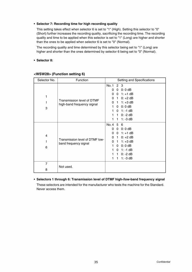
• Selector 7: Recording time for high recording quality
This setting takes effect when selector 6 is set to "1" (High). Setting this selector to "0" (Short) further increases the recording quality, sacrificing the recording time. The recording quality and time to be applied when this selector is set to "1" (Long) are higher and shorter than the ones to be applied when selector 6 is set to "0" (Normal).
The recording quality and time determined by this selector being set to "1" (Long) are higher and shorter than the ones determined by selector 6 being set to "0" (Normal).
• Selector 8:
<WSW28> (Function setting 6)
• Selectors 1 through 6: Transmission level of DTMF high-/low-band frequency signal
These selectors are intended for the manufacturer who tests the machine for the Standard. Never access them.
Selector No. Function Setting and Specifications
1
I
3
Transmission level of DTMF high-band frequency signal
No. 1 2 30 0 0: 0 dB0 0 1: +1 dB0 1 0: +2 dB0 1 1: +3 dB1 0 0: 0 dB1 0 1: -1 dB1 1 0: -2 dB1 1 1: -3 dB
4
I
6
Transmission level of DTMF low-band frequency signal
No. 4 5 60 0 0: 0 dB0 0 1: +1 dB0 1 0: +2 dB0 1 1: +3 dB1 0 0: 0 dB1 0 1: -1 dB1 1 0: -2 dB1 1 1: -3 dB
7
8Not used.

36 Confidential
<WSW29> (Function setting 7)
• Selectors 1 through 6:Compression threshold level for voice signals inputted via the telephone line and handset in the built-in TAD operation
If voice signals inputted via the telephone line are below the level specified by these selectors, the TAD interprets those received voice signals as no signal, compressing the recording time.
• Selector 8: Prompt beep for activity report
This selector determines whether or not to beep if the memory area for the activity report becomes full, for prompting you to print out the report. (Printing it out will clear the memory area.)
Selector No. Function Setting and Specifications
1
I
3
Compression threshold level for voice signals inputted via the telephone line in the built-in TAD operation
No. 1 2 30 0 0: -47.0 dBm (A)0 0 1: -48.5 dBm (B)0 1 0: -50.0 dBm (C)0 1 1: -51.5 dBm (D)1 0 0: -53.0 dBm (E)1 0 1: -54.5 dBm (F)1 1 0: -56.0 dBm (G)1 1 1: OFF (H)
4
I
6
Compression threshold level for voice signals inputted via the handset in the built-in TAD operation
No. 4 5 60 0 0: -44.0 dBm (A)0 0 1: -45.5 dBm (B)0 1 0: -47.0 dBm (C)0 1 1: -48.5 dBm (D)1 0 0: -50.0 dBm (E)1 0 1: -51.5 dBm (F)1 1 0: -53.0 dBm (G)1 1 1: OFF (H)
7 Impedance switching control in pulse dialing 0: OFF 1: ON
8Prompt beep when the memory area for the activity report becomes full
0: No 1: Yes
Note:• Selectors 1 through 6 are applicable to models equipped with built-in TADs.
• Selectors 7 and 8 are applicable only to the European versions.
37 Confidential
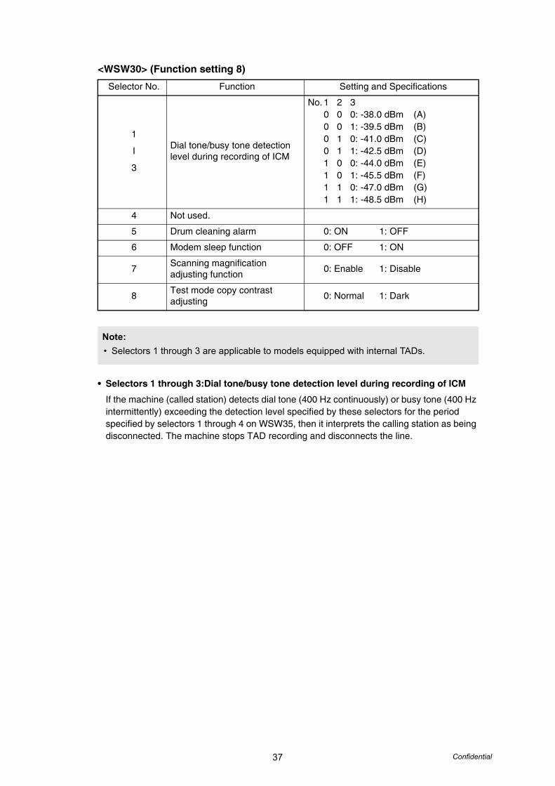
<WSW30> (Function setting 8)
• Selectors 1 through 3:Dial tone/busy tone detection level during recording of ICM
If the machine (called station) detects dial tone (400 Hz continuously) or busy tone (400 Hz intermittently) exceeding the detection level specified by these selectors for the period specified by selectors 1 through 4 on WSW35, then it interprets the calling station as being disconnected. The machine stops TAD recording and disconnects the line.
Selector No. Function Setting and Specifications
1
I
3
Dial tone/busy tone detection level during recording of ICM
No. 1 2 30 0 0: -38.0 dBm (A)0 0 1: -39.5 dBm (B)0 1 0: -41.0 dBm (C)0 1 1: -42.5 dBm (D)1 0 0: -44.0 dBm (E)1 0 1: -45.5 dBm (F)1 1 0: -47.0 dBm (G)1 1 1: -48.5 dBm (H)
4 Not used.
5 Drum cleaning alarm 0: ON 1: OFF
6 Modem sleep function 0: OFF 1: ON
7 Scanning magnification adjusting function 0: Enable 1: Disable
8 Test mode copy contrast adjusting 0: Normal 1: Dark
Note:• Selectors 1 through 3 are applicable to models equipped with internal TADs.

38 Confidential
<WSW31> (Function setting 9)
• Selector 2: Default reduction rate for failure of automatic reduction during recording
This selector sets the default reduction rate to be applied if the automatic reduction function fails to record one-page data sent from the calling station in a single page of the current recording paper.
If it is set to "0," the machine records one-page data at full size (100%) without reduction; if it is set to "1," the machine records it at 70% size.
• Selector 5: Minimum ON and OFF duration of ringer signals effective in distinctive ringing
The ringer pattern consists of short and long rings, e.g., short-short-long rings. This selector sets the minimum ON and OFF duration of ringer signals that are required for the machine to interpret ringer signals as being ON or OFF. This is to prevent components of a ringer pattern from being misinterpreted due to chattering in distinctive ringing.
The machine monitors ringer signals at 10-ms intervals. If the signal is ON, the machine counts +1; if it is OFF, it counts -1. If the counter increments up to +5 or +13 when this selector is set to "1" (90 ms) or "0" (130 ms), respectively, the machine interprets the current signal as being ON.
If the counter returns to zero, the machine interprets the signal as being OFF.If the Distinctive Ring is set to OFF, this selector is not effective.
• Selector 8: Drum life indication
This selector selects whether display the LCD message at the "Drum life end soon," or not.
Selector No. Function Setting and Specifications
1 Not used.
2Default reduction rate for failure of automatic reduction during recording
0: 100 % 1: 75 %
3 Not used.
4 (Do not disturb this selector.)
5Minimum ON and OFF duration of ringer signals effective in distinctive ringing
0: 130 ms 1: 90 ms
6
7Not used.
8 Drum life indication 0: No 1: Yes
Note:• Selector 5 is applicable only to the U.S.A. models.
39 Confidential
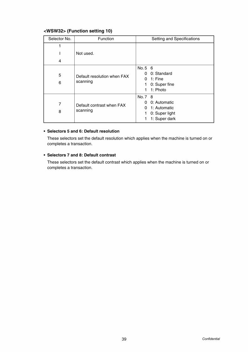
<WSW32> (Function setting 10)
• Selectors 5 and 6: Default resolution
These selectors set the default resolution which applies when the machine is turned on or completes a transaction.
• Selectors 7 and 8: Default contrast
These selectors set the default contrast which applies when the machine is turned on or completes a transaction.
Selector No. Function Setting and Specifications
1
I
4
Not used.
5
6Default resolution when FAX scanning
No. 5 60 0: Standard0 1: Fine1 0: Super fine1 1: Photo
7
8Default contrast when FAX scanning
No. 7 80 0: Automatic0 1: Automatic1 0: Super light1 1: Super dark
40 Confidential
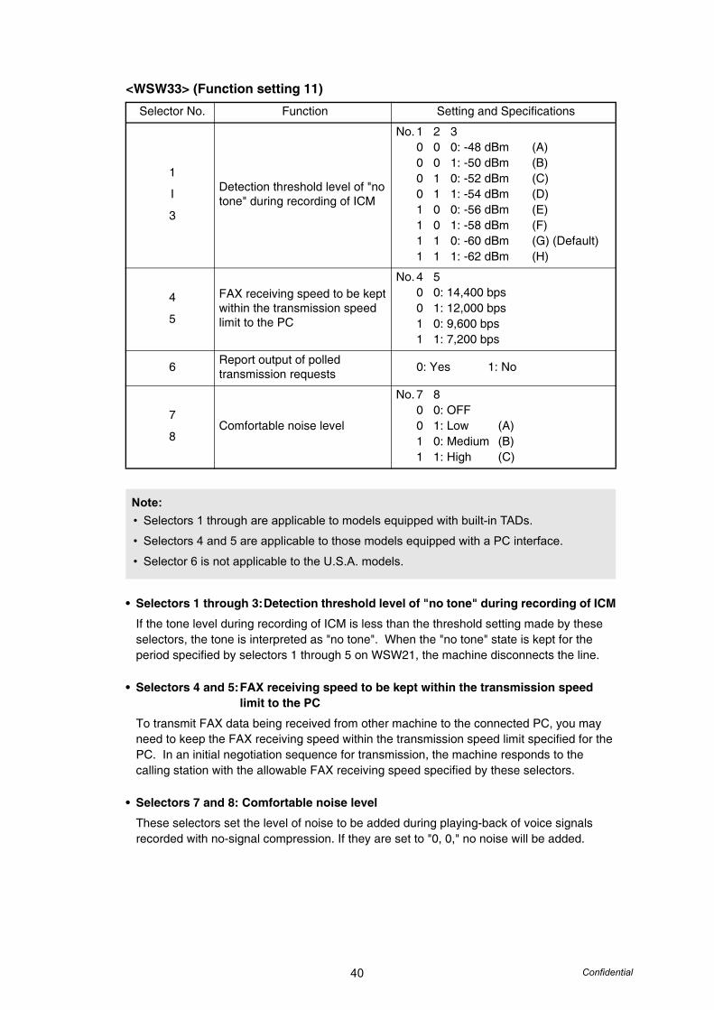
<WSW33> (Function setting 11)
• Selectors 1 through 3:Detection threshold level of "no tone" during recording of ICM
If the tone level during recording of ICM is less than the threshold setting made by these selectors, the tone is interpreted as "no tone". When the "no tone" state is kept for the period specified by selectors 1 through 5 on WSW21, the machine disconnects the line.
• Selectors 4 and 5:FAX receiving speed to be kept within the transmission speed limit to the PC
To transmit FAX data being received from other machine to the connected PC, you may need to keep the FAX receiving speed within the transmission speed limit specified for the PC. In an initial negotiation sequence for transmission, the machine responds to the calling station with the allowable FAX receiving speed specified by these selectors.
• Selectors 7 and 8: Comfortable noise level
These selectors set the level of noise to be added during playing-back of voice signals recorded with no-signal compression. If they are set to "0, 0," no noise will be added.
Selector No. Function Setting and Specifications
1
I
3
Detection threshold level of "no tone" during recording of ICM
No. 1 2 30 0 0: -48 dBm (A)0 0 1: -50 dBm (B)0 1 0: -52 dBm (C)0 1 1: -54 dBm (D)1 0 0: -56 dBm (E)1 0 1: -58 dBm (F)1 1 0: -60 dBm (G) (Default)1 1 1: -62 dBm (H)
4
5
FAX receiving speed to be kept within the transmission speed limit to the PC
No. 4 50 0: 14,400 bps0 1: 12,000 bps1 0: 9,600 bps1 1: 7,200 bps
6 Report output of polled transmission requests 0: Yes 1: No
7
8Comfortable noise level
No. 7 80 0: OFF0 1: Low (A)1 0: Medium (B)1 1: High (C)
Note:• Selectors 1 through are applicable to models equipped with built-in TADs.
• Selectors 4 and 5 are applicable to those models equipped with a PC interface.
• Selector 6 is not applicable to the U.S.A. models.
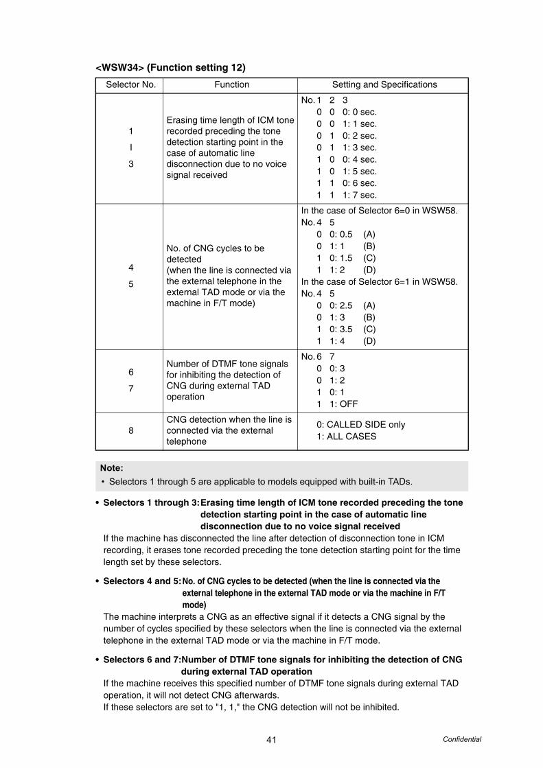
41 Confidential
<WSW34> (Function setting 12)
• Selectors 1 through 3:Erasing time length of ICM tone recorded preceding the tone detection starting point in the case of automatic line disconnection due to no voice signal received
If the machine has disconnected the line after detection of disconnection tone in ICM recording, it erases tone recorded preceding the tone detection starting point for the time length set by these selectors.
• Selectors 4 and 5:No. of CNG cycles to be detected (when the line is connected via the external telephone in the external TAD mode or via the machine in F/T mode)
The machine interprets a CNG as an effective signal if it detects a CNG signal by the number of cycles specified by these selectors when the line is connected via the external telephone in the external TAD mode or via the machine in F/T mode.
• Selectors 6 and 7:Number of DTMF tone signals for inhibiting the detection of CNG during external TAD operation
If the machine receives this specified number of DTMF tone signals during external TAD operation, it will not detect CNG afterwards.If these selectors are set to "1, 1," the CNG detection will not be inhibited.
Selector No. Function Setting and Specifications
1
I
3
Erasing time length of ICM tone recorded preceding the tone detection starting point in the case of automatic line disconnection due to no voice signal received
No. 1 2 30 0 0: 0 sec.0 0 1: 1 sec.0 1 0: 2 sec.0 1 1: 3 sec.1 0 0: 4 sec.1 0 1: 5 sec.1 1 0: 6 sec.1 1 1: 7 sec.
4
5
No. of CNG cycles to be detected (when the line is connected via the external telephone in the external TAD mode or via the machine in F/T mode)
In the case of Selector 6=0 in WSW58.No. 4 5
0 0: 0.5 (A)0 1: 1 (B)1 0: 1.5 (C)1 1: 2 (D)
In the case of Selector 6=1 in WSW58.No. 4 5
0 0: 2.5 (A)0 1: 3 (B)1 0: 3.5 (C)1 1: 4 (D)
6
7
Number of DTMF tone signals for inhibiting the detection of CNG during external TAD operation
No. 6 70 0: 30 1: 21 0: 11 1: OFF
8CNG detection when the line is connected via the external telephone
0: CALLED SIDE only1: ALL CASES
Note:• Selectors 1 through 5 are applicable to models equipped with built-in TADs.
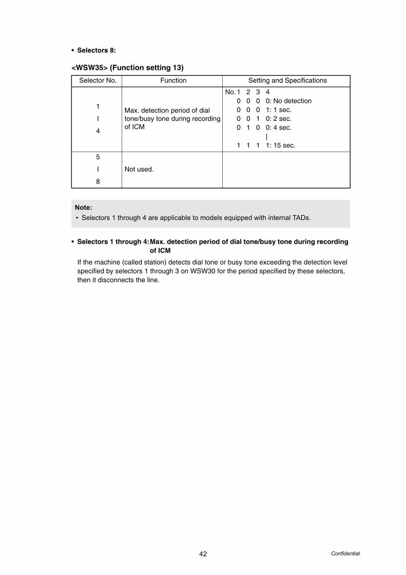
42 Confidential
• Selectors 8:
<WSW35> (Function setting 13)
• Selectors 1 through 4:Max. detection period of dial tone/busy tone during recording of ICM
If the machine (called station) detects dial tone or busy tone exceeding the detection level specified by selectors 1 through 3 on WSW30 for the period specified by these selectors, then it disconnects the line.
Selector No. Function Setting and Specifications
1
I
4
Max. detection period of dial tone/busy tone during recording of ICM
No. 1 2 3 40 0 0 0: No detection0 0 0 1: 1 sec.0 0 1 0: 2 sec.0 1 0 0: 4 sec.
|1 1 1 1: 15 sec.
5
I
8
Not used.
Note:• Selectors 1 through 4 are applicable to models equipped with internal TADs.
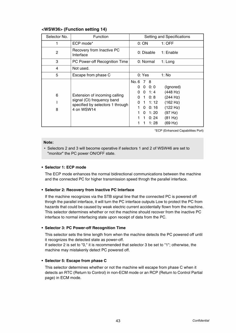
43 Confidential
<WSW36> (Function setting 14)
*ECP (Enhanced Capabilities Port)
• Selector 1: ECP mode
The ECP mode enhances the normal bidirectional communications between the machine and the connected PC for higher transmission speed throgh the parallel interface.
• Selector 2: Recovery from Inactive PC Interface
If the machine recognizes via the STB signal line that the connected PC is powered off throgh the parallel interface, it will turn the PC interface outputs Low to protect the PC from hazards that could be caused by weak electric current accidentally flown from the machine.This selector determines whether or not the machine should recover from the inactive PC interface to normal interfacing state upon receipt of data from the PC.
• Selector 3: PC Power-off Recognition Time
This selector sets the time length from when the machine detects the PC powered off until it recognizes the detected state as power-off.If selector 2 is set to "0," it is recommended that selector 3 be set to "1"; otherwise, the machine may mistakenly detect PC powered off.
• Selector 5: Escape from phase C
This selector determines whether or not the machine will escape from phase C when it detects an RTC (Return to Control) in non-ECM mode or an RCP (Return to Control Partial page) in ECM mode.
Selector No. Function Setting and Specifications
1 ECP mode* 0: ON 1: OFF
2 Recovery from Inactive PC Interface 0: Disable 1: Enable
3 PC Power-off Recognition Time 0: Normal 1: Long
4 Not used.
5 Escape from phase C 0: Yes 1: No
6
I
8
Extension of incoming calling signal (CI) frequency band specified by selectors 1 through 4 on WSW14
No. 6 7 80 0 0: 0 (Ignored)0 0 1: 4 (448 Hz)0 1 0: 8 (244 Hz)0 1 1: 12 (162 Hz)1 0 0: 16 (122 Hz)1 0 1: 20 (97 Hz)1 1 0: 24 (81 Hz)1 1 1: 28 (69 Hz)
Note:• Selectors 2 and 3 will become operative if selectors 1 and 2 of WSW46 are set to
"monitor" the PC power ON/OFF state.
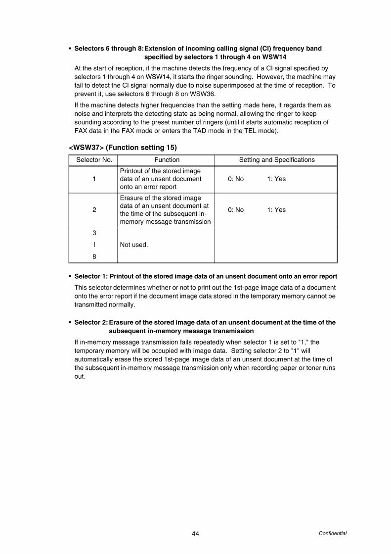
44 Confidential
• Selectors 6 through 8:Extension of incoming calling signal (CI) frequency band specified by selectors 1 through 4 on WSW14
At the start of reception, if the machine detects the frequency of a CI signal specified by selectors 1 through 4 on WSW14, it starts the ringer sounding. However, the machine may fail to detect the CI signal normally due to noise superimposed at the time of reception. To prevent it, use selectors 6 through 8 on WSW36.
If the machine detects higher frequencies than the setting made here, it regards them as noise and interprets the detecting state as being normal, allowing the ringer to keep sounding according to the preset number of ringers (until it starts automatic reception of FAX data in the FAX mode or enters the TAD mode in the TEL mode).
<WSW37> (Function setting 15)
• Selector 1: Printout of the stored image data of an unsent document onto an error report
This selector determines whether or not to print out the 1st-page image data of a document onto the error report if the document image data stored in the temporary memory cannot be transmitted normally.
• Selector 2:Erasure of the stored image data of an unsent document at the time of the subsequent in-memory message transmission
If in-memory message transmission fails repeatedly when selector 1 is set to "1," the temporary memory will be occupied with image data. Setting selector 2 to "1" will automatically erase the stored 1st-page image data of an unsent document at the time of the subsequent in-memory message transmission only when recording paper or toner runs out.
Selector No. Function Setting and Specifications
1Printout of the stored image data of an unsent document onto an error report
0: No 1: Yes
2
Erasure of the stored image data of an unsent document at the time of the subsequent in-memory message transmission
0: No 1: Yes
3
I
8
Not used.

45 Confidential
<WSW38> (V.34 transmission settings)
• Selectors 1 and 2: Setting of the equalizerThese selectors set the equalizer's training level to be applied if the machine fails to send training due to weak line connection. If these selectors are set to "0, X," the modem will automatically set the appropriate training level.
• Selector 3: Sending level of guard tone at phase 2This selector sets the sending level of guard tone for 1800 Hz to be sent at Phase 2 in the V. 34 mode.
• Selector 4: Stepping down the transmission speed at fallback eachThis selector determines how much the modem steps down the transmission speed at fallback when called by the remote station. If this selector is set to "1," the modem may step down the transmission speed from 33600 bps to 28800 bps by one-time fallback.
• Selectors 5 and 6:Automatic control of modem's EQM gain for proper transmission speed choiceThese selectors determine how the modem controls the EQM (Eye Quality Monitor) gain for proper choice of the transmission speed, which applies if the modem selects higher transmission speed than the possible speed so that it always repeats falling back.
• Selector 8: Detection of CED for stopping CNGIf this selector is set to "0," the detection time of CED specified by WSW43, selectors 4 and 5 will apply.
Selector No. Function Setting and Specifications
1
2Setting of the equalizer
No. 1 20 0: Automatic0 1: Automatic1 0: Fixed to 4 points1 1: Fixed to 16 points
3 Sending level of guard tone at phase 2 0: Normal - 7 db 1: Normal
4 Stepping down the transmission speed at fallback each 0: 2,400 bps 1: 4,800 bps
5
6
Automatic control of modem's EQM gain for proper transmission speed choice
No. 5 60 0: For higher transmission speed
than the current setting0 1: No change from the current
setting1 0: For lower transmission speed
than the current setting1 1: For further lower transmission
than the setting made by 1, 0
7 Redialing when a communications error occurs 0: ON 1: OFF
8 Detection of CED for stopping CNG 0: ON 1: OFF
Note:• WSW38 takes effect only when the V.34 mode is permitted (WSW19, selector 7) in
models supporting V.34 mode.
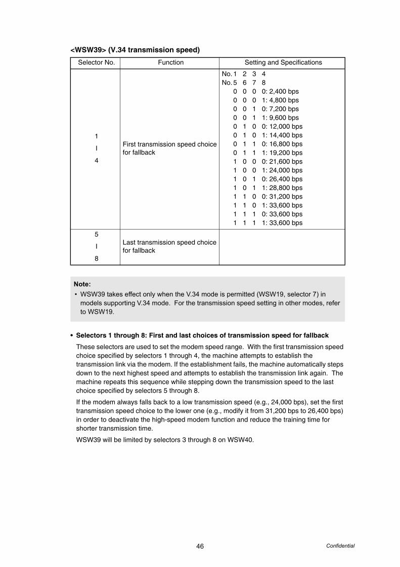
46 Confidential
<WSW39> (V.34 transmission speed)
• Selectors 1 through 8: First and last choices of transmission speed for fallback
These selectors are used to set the modem speed range. With the first transmission speed choice specified by selectors 1 through 4, the machine attempts to establish the transmission link via the modem. If the establishment fails, the machine automatically steps down to the next highest speed and attempts to establish the transmission link again. The machine repeats this sequence while stepping down the transmission speed to the last choice specified by selectors 5 through 8.
If the modem always falls back to a low transmission speed (e.g., 24,000 bps), set the first transmission speed choice to the lower one (e.g., modify it from 31,200 bps to 26,400 bps) in order to deactivate the high-speed modem function and reduce the training time for shorter transmission time.
WSW39 will be limited by selectors 3 through 8 on WSW40.
Selector No. Function Setting and Specifications
1
I
4
First transmission speed choice for fallback
No. 1 2 3 4No. 5 6 7 8
0 0 0 0: 2,400 bps0 0 0 1: 4,800 bps0 0 1 0: 7,200 bps0 0 1 1: 9,600 bps0 1 0 0: 12,000 bps0 1 0 1: 14,400 bps0 1 1 0: 16,800 bps0 1 1 1: 19,200 bps1 0 0 0: 21,600 bps1 0 0 1: 24,000 bps1 0 1 0: 26,400 bps1 0 1 1: 28,800 bps1 1 0 0: 31,200 bps1 1 0 1: 33,600 bps1 1 1 0: 33,600 bps1 1 1 1: 33,600 bps
5
I
8
Last transmission speed choice for fallback
Note:• WSW39 takes effect only when the V.34 mode is permitted (WSW19, selector 7) in
models supporting V.34 mode. For the transmission speed setting in other modes, refer to WSW19.

47 Confidential
<WSW40> (V.34 modem settings)
• Selectors 3 through 8: Masking of symbol rate(s)
These selectors allow you to limit the transmission speed range in V.34 mode by masking the desired symbol rate(s). Transmission speeds assigned to the symbol rates are listed on the next page. The setting made by these selectors will limit the setting made by selectors 1 through 4 on WSW39.
If selector 3 is set to "1" to mask the 3429 symbols/second when the first transmission speed choice is 33600 bps (specified by selectors 1 through 4 of WSW39), for example, then the allowable maximum transmission speed will be limited to 31200 bps. If selector 8 is set to "1" to mask the 2400 symbols/second when the first transmission speed choice is 33600 bps, then the allowable maximum transmission speed remains 33600 bps.
If selector 8 is set to "1" to mask the 2400 symbols/second when the first transmission speed choice is 21600 bps (specified by selectors 1 through 4 on WSW39), then the allowable maximum transmission speed remains 21600 bps but the minimum transmission speed will be limited to 4800 bps.
Selector No. Function Setting and Specifications
1 Busy / Ring Feature 0: OFF 1: ON
2 Not used.
3
I
8
Masking of symbol rate(s)
Not masking MaskingNo. 3 0 1 3429 symbols/secNo. 4 0 1 3200 symbols/secNo. 5 0 1 3000 symbols/secNo. 6 0 1 2800 symbols/secNo. 7 - - Not used.No. 8 0 1 2400 symbols/sec
Note:• WSW40 takes effect only when the V.34 mode is permitted (WSW19, selector 7) in
models supporting V.34 mode.
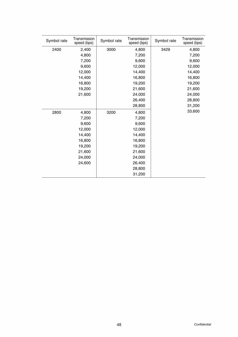
48 Confidential
Symbol rate Transmission speed (bps) Symbol rate Transmission
speed (bps) Symbol rate Transmission speed (bps)
2400 2,4004,8007,2009,600
12,00014,40016,80019,20021,600
3000 4,8007,2009,600
12,00014,40016,80019,20021,60024,00026,40028,800
3429 4,8007,2009,600
12,00014,40016,80019,20021,60024,00028,80031,20033,6002800 4,800
7,2009,600
12,00014,40016,80019,20021,60024,00024,600
3200 4,8007,2009,600
12,00014,40016,80019,20021,60024,00026,40028,80031,200
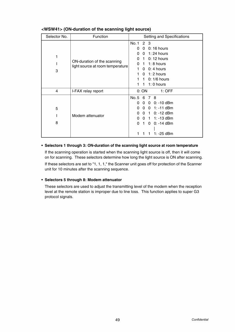
49 Confidential
<WSW41> (ON-duration of the scanning light source)
• Selectors 1 through 3: ON-duration of the scanning light source at room temperature
If the scanning operation is started when the scanning light source is off, then it will come on for scanning. These selectors determine how long the light source is ON after scanning.
If these selectors are set to "1, 1, 1," the Scanner unit goes off for protection of the Scanner unit for 10 minutes after the scanning sequence.
• Selectors 5 through 8: Modem attenuator
These selectors are used to adjust the transmitting level of the modem when the reception level at the remote station is improper due to line loss. This function applies to super G3 protocol signals.
Selector No. Function Setting and Specifications
1
I
3
ON-duration of the scanning light source at room temperature
No. 1 2 30 0 0: 16 hours0 0 1: 24 hours0 1 0: 12 hours0 1 1: 8 hours1 0 0: 4 hours1 0 1: 2 hours1 1 0: 1/6 hours1 1 1: 0 hours
4 I-FAX relay report 0: ON 1: OFF
5
I
8
Modem attenuator
No. 5 6 7 80 0 0 0: -10 dBm0 0 0 1: -11 dBm0 0 1 0: -12 dBm0 0 1 1: -13 dBm0 1 0 0: -14 dBm
|1 1 1 1: -25 dBm

50 Confidential
<WSW42> (Internet mail settings)
• Selector 4: JBIG encoding system
This selector eliminates the malfunction by setting to "0" (the sending the DIS of the FIF set to 6 bytes from 7 bytes) if the machine malfunctions in the sending the DIS of the FIF.
• Selector 5: Drum discharge detection
Laser model only
Selector No. Function Setting and Specifications
1Access to the incoming mail (POP3) server (Periodical or on-demand)
0: OFF 1: ON
2 Access to the outgoing mail (SMTP) server 0: OFF 1: ON
3 I-FAX relay 0: OFF 1: ON
4 JBIG encoding system 0: Not allowed 1: Allowed
5 Drum discharge detection 0: ON 1: OFF
6
I
8
Not used.

51 Confidential
<WSW43> (Function setting 16)
• Selector 1: Header for sent mail (Station ID)
This selector set whether add the header (Station ID) to the image data of the reading sent mail. (only with LAN model)
• Selectors 4 and 5: Detection time of 2100 Hz CED or ANSam
These selectors are effective only V.34 model.
• Selector 8: JPEG coding
Setting this selector to "0" disables the machine from sending/receiving JPEG color images and from receiving JPEG monochrome images.
Selector No. Function Setting and Specifications
1 Header for sent mail (Station ID) 0: Yes 1: No
2
3
Wait time for PC-Fax reception (Class 2) and FPTS command transmission
No. 2 30 0: 50 ms0 1: 100 ms1 0: 150 ms1 1: 0 ms
4
5Detection time of 2100 Hz CED or ANSam
No. 4 50 0: 200 ms0 1: 300 ms1 0: 400 ms1 1: 500 ms
6 Not used.
7 Automatic start of remote maintenance 0: No 1: Yes
8 JPEG coding 0: Disable 1: Enable

52 Confidential
<WSW44> (Speeding up scanning-1)
• Selectors 6 through 8:Effective time length of the white level compensation data obtained beforehand
These selectors determine how long compensation data obtained beforehand will keep effective.
Selector No. Function Setting and Specifications
1
I
5
Copying speed control
No. 1 2 3 4 50 0 0 0 0: Max.0 0 0 0 1: 1ppm
|1 1 1 1 1: 31ppm
6
I
8
Effective time length of the white level compensation data obtained beforehand
No. 6 7 80 0 0: Obtained compensation
data ineffective0 0 1: 1 min.0 1 0: 3 min.0 1 1: 5 min.1 0 0: 10 min.1 0 1: 15 min.1 1 0: 20 min.1 1 1: 30 min.
Note:• Selectors 6 through 8 are applicable to flat head-type models only.
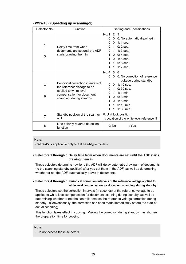
53 Confidential
<WSW45> (Speeding up scanning-2)
• Selectors 1 through 3:Delay time from when documents are set until the ADF starts drawing them in
These selectors determine how long the ADF will delay automatic drawing-in of documents (to the scanning standby position) after you set them in the ADF, as well as determining whether or not the ADF automatically draws in documents.
• Selectors 4 through 6:Periodical correction intervals of the reference voltage applied to white level compensation for document scanning, during standby
These selectors set the correction intervals (in seconds) of the reference voltage to be applied to white level compensation for document scanning during standby, as well as determining whether or not the controller makes the reference voltage correction during standby. (Conventionally, the correction has been made immediately before the start of actual scanning)
This function takes effect in copying. Making the correction during standby may shorten the preparation time for copying.
Selector No. Function Setting and Specifications
1
I
3
Delay time from when documents are set until the ADF starts drawing them in
No. 1 2 30 0 0: No automatic drawing-in0 0 1: 1 sec.0 1 0: 2 sec.0 1 1: 3 sec.1 0 0: 4 sec.1 0 1: 5 sec.1 1 0: 6 sec.1 1 1: 7 sec.
4
I
6
Periodical correction intervals of the reference voltage to be applied to white level compensation for document scanning, during standby
No. 4 5 60 0 0: No correction of reference
voltage during standby0 0 1: 10 sec.0 1 0: 30 sec.0 1 1: 1 min.1 0 0: 3 min.1 0 1: 5 min.1 1 0: 10 min.1 1 1: 30 min.
7 Standby position of the scanner unit
0: Unit lock position1: Location of the white-level reference film
8 Line polarity reverse detection function 0: No 1: Yes
Note:• WSW45 is applicable only to flat head-type models.
Note:• Do not access these selectors.

54 Confidential
• Selector 7: Standby position of the scanner unit
This selector determines whether the standby position of the scanner unit should be the unit lock position or the location of the white-level reference film (attached to the inside of the scanner top cover). If the location of the reference film is selected, the scanner unit will not return to the home position so as to shorten the travel time, decreasing the preparation time for copying.
• Selector 8: Line polarity reverse detection function
Line polarity will be reversed if the phone is hung up at the other end of the line. If this selector is set to "1," the machine will detect the reverse polarity during an answering machine operation and thereby determine that the phone has been hung up.
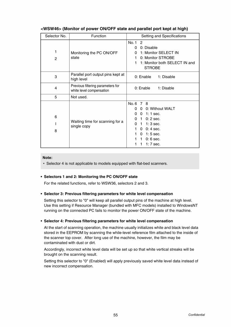
55 Confidential
<WSW46> (Monitor of power ON/OFF state and parallel port kept at high)
• Selectors 1 and 2: Monitoring the PC ON/OFF state
For the related functions, refer to WSW36, selectors 2 and 3.
• Selector 3: Previous filtering parameters for white level compensation
Setting this selector to "0" will keep all parallel output pins of the machine at high level. Use this setting if Resource Manager (bundled with MFC models) installed to WindowsNT running on the connected PC fails to monitor the power ON/OFF state of the machine.
• Selector 4: Previous filtering parameters for white level compensation
At the start of scanning operation, the machine usually initializes white and black level data stored in the EEPROM by scanning the while-level reference film attached to the inside of the scanner top cover. After long use of the machine, however, the film may be contaminated with dust or dirt.
Accordingly, incorrect white level data will be set up so that white vertical streaks will be brought on the scanning result.
Setting this selector to "0" (Enabled) will apply previously saved white level data instead of new incorrect compensation.
Selector No. Function Setting and Specifications
1
2Monitoring the PC ON/OFF state
No. 1 20 0: Disable0 1: Monitor SELECT IN1 0: Monitor STROBE1 1: Monitor both SELECT IN and
STROBE
3 Parallel port output pins kept at high level 0: Enable 1: Disable
4 Previous filtering parameters for white level compensation 0: Enable 1: Disable
5 Not used.
6
I
8
Waiting time for scanning for a single copy
No. 6 7 80 0 0: Without WALT0 0 1: 1 sec.0 1 0: 2 sec.0 1 1: 3 sec.1 0 0: 4 sec.1 0 1: 5 sec.1 1 0: 6 sec.1 1 1: 7 sec.
Note:• Selector 4 is not applicable to models equipped with flat-bed scanners.

56 Confidential
<WSW47> (Switching between high- and full-speed USB)
• Selector 1: Handling paper at the occurrence of a paper feed timing error
When feeding paper to the print start position, the machine might cause a feed timing error so that the registration sensor goes ON signaling the presence of paper. This selector determines whether the machine prints on the current paper or ejects the current paper without printing and prints on the next paper.
• Selector 2: Reducing to B4 from A4 and sending at the real time sending
Setting this selector to "1" reduces the document size from B4 to A4 in real-time transmission.
• Selectors 3 and 4: Delay of FAX line disconnection when switching to the pseudo-ringing external telephone
When the machine receives a phone call, it can make the connected external telephone ring (so called pseudo-ringing). During pseudo-ringing, if you pick up the handset of the external telephone, the line might be disconnected due to cut-off of the line current. To hold the line, the machine may supply line current by making use of the pulse generator circuit that forms a parallel loop. This way the FAX line disconnection may be delayed. These selectors determine the delay period.
Selector No. Function Setting and Specifications
1Handling paper at the occurrence of a paper feed timing error
0: Eject paper w/o print1: Print on the current paper
2 Reducing to B4 from A4 and sending at the real time sending 0: No 1: Yes
3
4
Delay of FAX line disconnection when switching to the pseudo-ringing external telephone
No. 3 40 0: 200 ms0 1: 400 ms1 0: 700 ms1 1: 1000 ms
5 Disable the ringer of external telephone at non-ring reception 0: No 1: Yes
6 Not used.
7Disable the ringer of external telephone with CAR signal when caller ID service is available
0: No 1: Yes
8 Switching between high-speed USB and full-speed USB
0: Auto switching between high-speed USB (ver. 2.0) and full-speed USB (ver. 1.1)
1: Fixed to full-speed USB (ver. 1.1)
Note:• Selector 1 is applicable only to models equipped with flat-bed scanners.
• Selectors 3 and 4 are applicable only to models supporting pseudo-ringing of a connected external telephone.
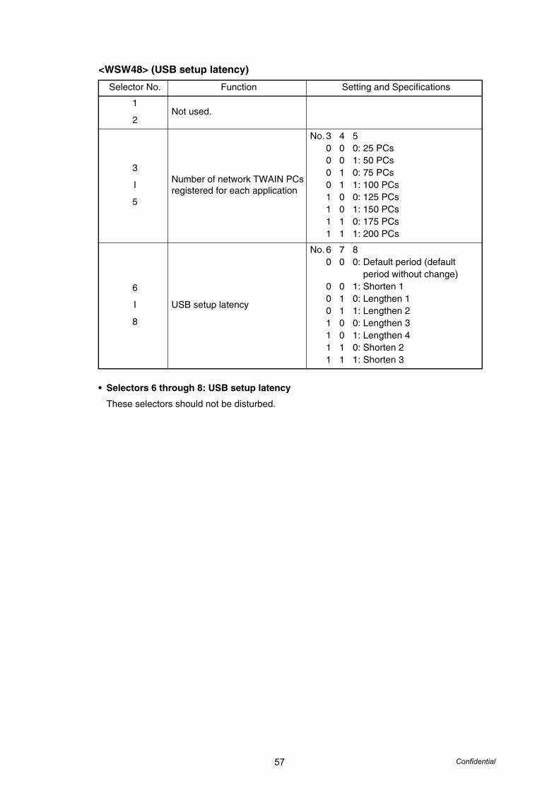
57 Confidential
<WSW48> (USB setup latency)
• Selectors 6 through 8: USB setup latency
These selectors should not be disturbed.
Selector No. Function Setting and Specifications
1
2Not used.
3
I
5
Number of network TWAIN PCs registered for each application
No. 3 4 50 0 0: 25 PCs0 0 1: 50 PCs0 1 0: 75 PCs0 1 1: 100 PCs1 0 0: 125 PCs1 0 1: 150 PCs1 1 0: 175 PCs1 1 1: 200 PCs
6
I
8
USB setup latency
No. 6 7 80 0 0: Default period (default
period without change)0 0 1: Shorten 10 1 0: Lengthen 10 1 1: Lengthen 21 0 0: Lengthen 31 0 1: Lengthen 41 1 0: Shorten 21 1 1: Shorten 3
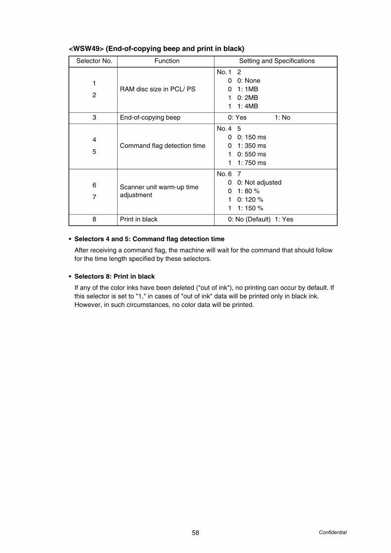
58 Confidential
<WSW49> (End-of-copying beep and print in black)
• Selectors 4 and 5: Command flag detection time
After receiving a command flag, the machine will wait for the command that should follow for the time length specified by these selectors.
• Selectors 8: Print in black
If any of the color inks have been deleted ("out of ink"), no printing can occur by default. If this selector is set to "1," in cases of "out of ink" data will be printed only in black ink. However, in such circumstances, no color data will be printed.
Selector No. Function Setting and Specifications
1
2RAM disc size in PCL/ PS
No. 1 20 0: None0 1: 1MB1 0: 2MB1 1: 4MB
3 End-of-copying beep 0: Yes 1: No
4
5Command flag detection time
No. 4 50 0: 150 ms0 1: 350 ms1 0: 550 ms1 1: 750 ms
6
7Scanner unit warm-up time adjustment
No. 6 70 0: Not adjusted0 1: 80 %1 0: 120 %1 1: 150 %
8 Print in black 0: No (Default) 1: Yes
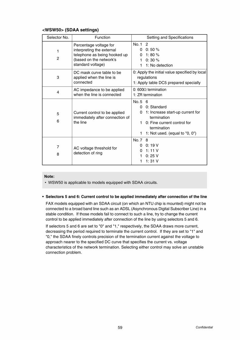
59 Confidential
<WSW50> (SDAA settings)
• Selectors 5 and 6: Current control to be applied immediately after connection of the line
FAX models equipped with an SDAA circuit (on which an NTU chip is mounted) might not be connected to a broad band line such as an ADSL (Asynchronous Digital Subscriber Line) in a stable condition. If those models fail to connect to such a line, try to change the current control to be applied immediately after connection of the line by using selectors 5 and 6.
If selectors 5 and 6 are set to "0" and "1," respectively, the SDAA draws more current, decreasing the period required to terminate the current control. If they are set to "1" and "0," the SDAA finely controls precision of the termination current against the voltage to approach nearer to the specified DC curve that specifies the current vs. voltage characteristics of the network termination. Selecting either control may solve an unstable connection problem.
Selector No. Function Setting and Specifications
1
2
Percentage voltage for interpreting the external telephone as being hooked up(based on the network's standard voltage)
No. 1 20 0: 50 %0 1: 80 %1 0: 30 %1 1: No detection
3DC mask curve table to be applied when the line is connected
0: Apply the initial value specified by local regulations1: Apply table DC5 prepared specially
4 AC impedance to be applied when the line is connected
0: 600Ω termination1: ZR termination
5
6
Current control to be applied immediately after connection of the line
No. 5 60 0: Standard0 1: Increase start-up current for
termination1 0: Fine current control for
termination1 1: Not used. (equal to "0, 0")
7
8AC voltage threshold for detection of ring
No. 7 80 0: 19 V0 1: 11 V1 0: 25 V1 1: 31 V
Note:• WSW50 is applicable to models equipped with SDAA circuits.
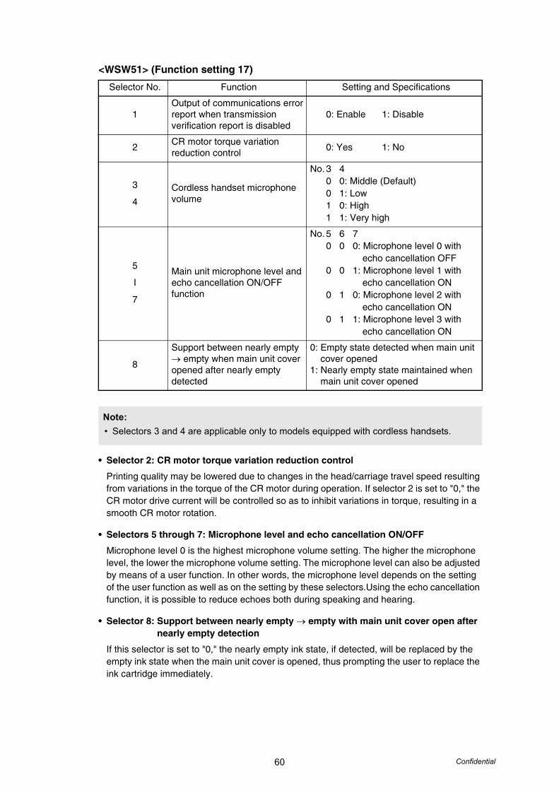
60 Confidential
<WSW51> (Function setting 17)
• Selector 2: CR motor torque variation reduction control
Printing quality may be lowered due to changes in the head/carriage travel speed resulting from variations in the torque of the CR motor during operation. If selector 2 is set to "0," the CR motor drive current will be controlled so as to inhibit variations in torque, resulting in a smooth CR motor rotation.
• Selectors 5 through 7: Microphone level and echo cancellation ON/OFF
Microphone level 0 is the highest microphone volume setting. The higher the microphone level, the lower the microphone volume setting. The microphone level can also be adjusted by means of a user function. In other words, the microphone level depends on the setting of the user function as well as on the setting by these selectors.Using the echo cancellation function, it is possible to reduce echoes both during speaking and hearing.
• Selector 8: Support between nearly empty → empty with main unit cover open after nearly empty detection
If this selector is set to "0," the nearly empty ink state, if detected, will be replaced by the empty ink state when the main unit cover is opened, thus prompting the user to replace the ink cartridge immediately.
Selector No. Function Setting and Specifications
1Output of communications error report when transmission verification report is disabled
0: Enable 1: Disable
2 CR motor torque variation reduction control 0: Yes 1: No
3
4Cordless handset microphone volume
No. 3 40 0: Middle (Default)0 1: Low1 0: High1 1: Very high
5
I
7
Main unit microphone level and echo cancellation ON/OFF function
No. 5 6 70 0 0: Microphone level 0 with
echo cancellation OFF0 0 1: Microphone level 1 with
echo cancellation ON0 1 0: Microphone level 2 with
echo cancellation ON0 1 1: Microphone level 3 with
echo cancellation ON
8
Support between nearly empty → empty when main unit cover opened after nearly empty detected
0: Empty state detected when main unit cover opened1: Nearly empty state maintained when main unit cover opened
Note:• Selectors 3 and 4 are applicable only to models equipped with cordless handsets.
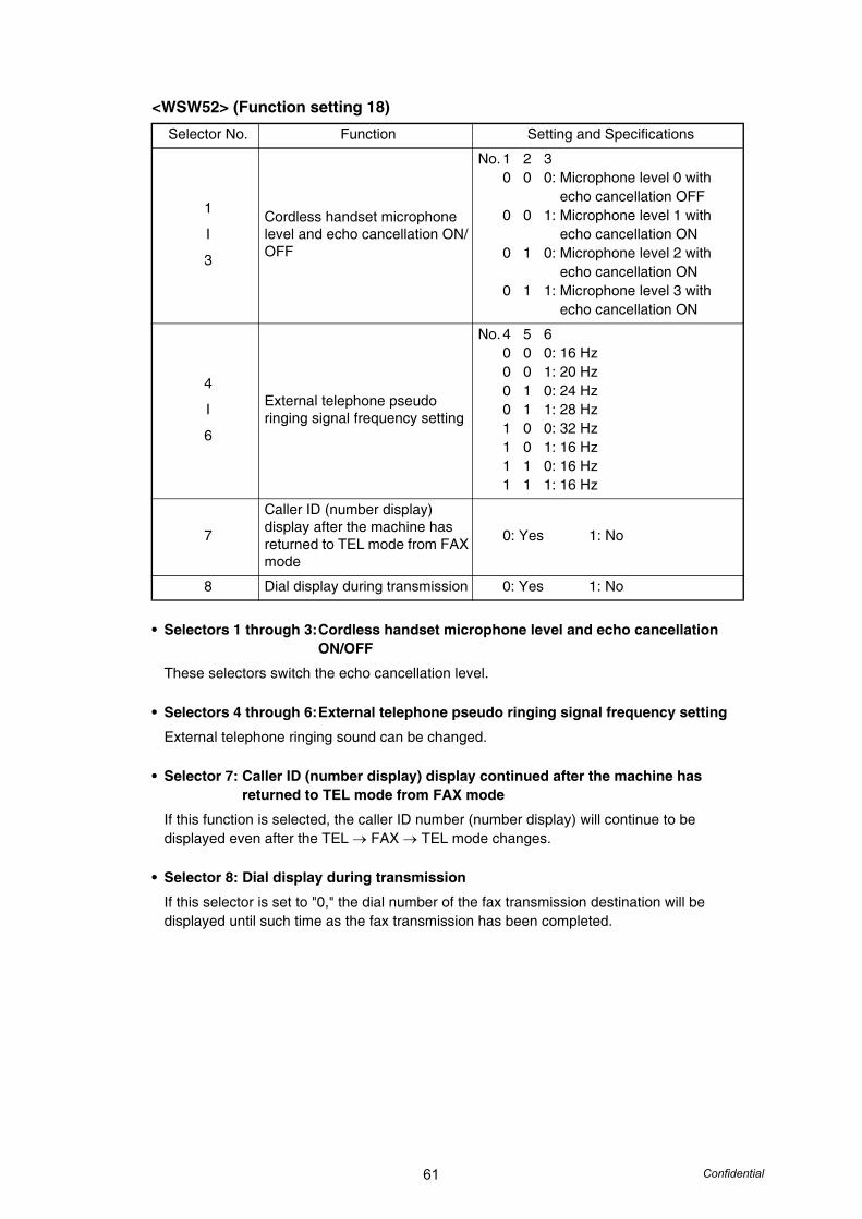
61 Confidential
<WSW52> (Function setting 18)
• Selectors 1 through 3:Cordless handset microphone level and echo cancellation ON/OFF
These selectors switch the echo cancellation level.
• Selectors 4 through 6:External telephone pseudo ringing signal frequency setting
External telephone ringing sound can be changed.
• Selector 7: Caller ID (number display) display continued after the machine has returned to TEL mode from FAX mode
If this function is selected, the caller ID number (number display) will continue to be displayed even after the TEL → FAX → TEL mode changes.
• Selector 8: Dial display during transmission
If this selector is set to "0," the dial number of the fax transmission destination will be displayed until such time as the fax transmission has been completed.
Selector No. Function Setting and Specifications
1
I
3
Cordless handset microphone level and echo cancellation ON/OFF
No. 1 2 30 0 0: Microphone level 0 with
echo cancellation OFF0 0 1: Microphone level 1 with
echo cancellation ON0 1 0: Microphone level 2 with
echo cancellation ON0 1 1: Microphone level 3 with
echo cancellation ON
4
I
6
External telephone pseudo ringing signal frequency setting
No. 4 5 60 0 0: 16 Hz0 0 1: 20 Hz0 1 0: 24 Hz0 1 1: 28 Hz1 0 0: 32 Hz1 0 1: 16 Hz1 1 0: 16 Hz1 1 1: 16 Hz
7
Caller ID (number display) display after the machine has returned to TEL mode from FAX mode
0: Yes 1: No
8 Dial display during transmission 0: Yes 1: No

62 Confidential
<WSW53> (Function setting 19)
• Selectors 3 through 6:Caller ID (number display) FSK receiving timing delay setting and instantaneous interrupt detection time setting
If a call error occurs during use of caller ID (number display), it may be possible for the error to be corrected by adjustment these selectors. If the error cannot be thus corrected, try adjusting selectors 5 and 6.
• Selector 8: Decompression of JPEG compressed file
Decompress JPEG compressed files stored on the inserted memory card. (ASIC: application specified integrated circuit)., JPEG compressed files can be decompressed with an ASIC. If an image fails to be replayed correctly due to a decompression error, set this selector to "1" and use other proven decompression software instead.
Selector No. Function Setting and Specifications
1
2Not used.
3
4Caller ID (number display) FSK receiving timing delay setting
No. 3 40 0: 0 ms0 1: 100 ms1 0: 150 ms1 1: 200 ms
5
6
Caller ID (number display) instantaneous interrupt detection time setting
No. 5 60 0: 20 ms0 1: 10 ms1 0: 30 ms1 1: 0 ms
7 CNG detection retry after invalid CNG detected 0: Yes 1: No
8 Decompression of JPEG compressed file
0: ASIC 1: Software (Default)
Note:• Selector 8 is applicable only to models equipped with photo media capture.
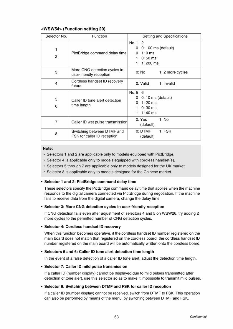
63 Confidential
<WSW54> (Function setting 20)
• Selector 1 and 2: PictBridge command delay time
These selectors specify the PictBridge command delay time that applies when the machine responds to the digital camera connected via PictBridge during negotiation. If the machine fails to receive data from the digital camera, change the delay time.
• Selector 3: More CNG detection cycles in user-friendly reception
If CNG detection fails even after adjustment of selectors 4 and 5 on WSW26, try adding 2 more cycles to the permitted number of CNG detection cycles.
• Selector 4: Cordless handset ID recovery
When this function becomes operative, if the cordless handset ID number registered on the main board does not match that registered on the cordless board, the cordless handset ID number registered on the main board will be automatically written onto the cordless board.
• Selectors 5 and 6: Caller ID tone alert detection time length
In the event of a false detection of a caller ID tone alert, adjust the detection time length.
• Selector 7: Caller ID mild pulse transmission
If a caller ID (number display) cannot be displayed due to mild pulses transmitted after detection of tone alert, use this selector so as to make it impossible to transmit mild pulses.
• Selector 8: Switching between DTMF and FSK for caller ID reception
If a caller ID (number display) cannot be received, switch from DTMF to FSK. This operation can also be performed by means of the menu, by switching between DTMF and FSK.
Selector No. Function Setting and Specifications
1
2PictBridge command delay time
No. 1 20 0: 100 ms (default)0 1: 0 ms1 0: 50 ms1 1: 200 ms
3 More CNG detection cycles in user-friendly reception 0: No 1: 2 more cycles
4 Cordless handset ID recovery future 0: Valid 1: Invalid
5
6Caller ID tone alert detection time length
No. 5 60 0: 10 ms (default)0 1: 20 ms1 0: 30 ms1 1: 40 ms
7 Caller ID wet pulse transmission0: Yes 1: No (default)
8 Switching between DTMF and FSK for caller ID reception
0: DTMF 1: FSK (default)
Note:• Selectors 1 and 2 are applicable only to models equipped with PictBridge.• Selector 4 is applicable only to models equipped with cordless handset(s).• Selectors 5 through 7 are applicable only to models designed for the UK market.• Selector 8 is applicable only to models designed for the Chinese market.
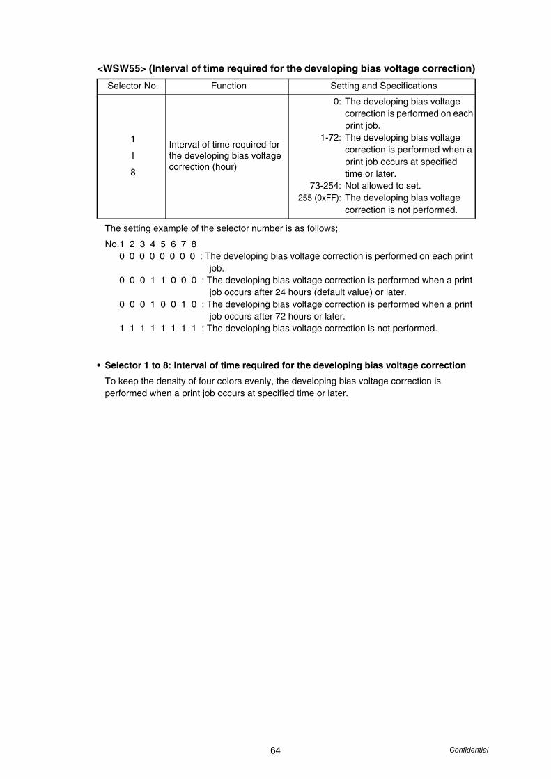
64 Confidential
<WSW55> (Interval of time required for the developing bias voltage correction)
The setting example of the selector number is as follows;
No.1 2 3 4 5 6 7 80 0 0 0 0 0 0 0 : The developing bias voltage correction is performed on each print
job.0 0 0 1 1 0 0 0 : The developing bias voltage correction is performed when a print
job occurs after 24 hours (default value) or later.0 0 0 1 0 0 1 0 : The developing bias voltage correction is performed when a print
job occurs after 72 hours or later.1 1 1 1 1 1 1 1 : The developing bias voltage correction is not performed.
• Selector 1 to 8: Interval of time required for the developing bias voltage correction
To keep the density of four colors evenly, the developing bias voltage correction is performed when a print job occurs at specified time or later.
Selector No. Function Setting and Specifications
1
I
8
Interval of time required for the developing bias voltage correction (hour)
0:
1-72:
73-254:255 (0xFF):
The developing bias voltage correction is performed on each print job.The developing bias voltage correction is performed when a print job occurs at specified time or later.Not allowed to set.The developing bias voltage correction is not performed.

65 Confidential
<WSW56> (Function setting 21)
• Selector 3: "Last Job Reprint" function setting
Setting this selector to "0" makes the machine not to reprint the "Last Job Print" data such as confidential document in order to prevent the misuse.
• Selector 4: Wireless LAN function
To disable the wireless LAN (WLAN) functions, set this selector to "1" and turn the machine power off and then on.
• Selector 5: Switching of the echo suppression improvement during calling
To suppress the echo during calling, set this selector to "0". The default value is "0:Enable".
• Selector 6: Switching of the display for the coverage of toner cartridge
This selector specifies the display for the coverage of toner cartridge. Setting this selector to "0", the machine displays the coverage only for the current toner cartridge. If this selector sets to "1", the machine displays the coverage for all toner cartridge which had been consumed.
• Selector 7: PCL emulation function setting
This selector is applicable to models equipped without PCL emulation.
• Selector 8: Switching of the CPU sleep mode
This selector specifies the CPU sleep mode ON or OFF.
Selector No. Function Setting and Specifications
1 PS emulation function setting 0: Invalid 1: Valid
2 Switching of the PPT setting 0: Invalid 1: Valid
3 "Last Job Reprint" function setting 0: Invalid 1: Valid
4 Wireless LAN function0: Enable(default)1: Disable
5Switching of the echo suppression improvement during calling
0: Enable 1: Disable
6 Switching of the display for the coverage of toner cartridge
0: The coverage only for the current toner cartridge
1: The coverage for all toner cartridges which had been consumed
7 PCL emulation function setting 0: Invalid 1: Valid
8 Switching of the CPU sleep mode 0: Invalid 1: Valid

66 Confidential
<WSW57> (Function setting 22)
• Selectors 1 through 3: Caller ID judgment voltage (to be distinguished from rings)
If caller IDs cannot be displayed because of confusion with rings due to variations in the voltage, increase the judgment voltage.However, do make sure that the voltage value set by selectors 1 through 3 of this switch is equal to, or greater than, the value set by selectors 4 through 6 of the same switch.
• Selectors 4 through 6: Caller ID judgment voltage (to be distinguished from reverse polarity voltages)
If caller IDs cannot be displayed because reverse polarities cannot be detected due to a large difference between line voltages in a reverse polarity condition and in a steady condition, increase the judgment voltage.However, do make sure that the voltage value set by selectors 1 through 3 of this switch is equal to, or greater than, the value set by selectors 4 through 6 of the same switch.
• Selector 8: Base unit [Start] button after cordless handset dialing
Even if the base unit [Start] button is pressed to start a FAX transmission during calling when this selector is in its default state, no FAX transmission will occur. By using this selector, it is possible to make the base unit [Start] button operative after cordless handset dialing.
Selector No. Function Setting and Specifications
1
I
3
Caller ID judgment voltage(to be distinguished from rings)
No. 1 2 30 0 0: 0 V0 0 1: 5 V (Default)0 1 0: 10 V0 1 1: 15 V1 0 0: 20 V1 0 1: 25 V1 1 0: 30 V1 1 1: Max.
4
I
6
Caller ID judgment voltage(to be distinguished from reverse polarity voltages)
No. 4 5 60 0 0: 0 V0 0 1: 5 V (Default)0 1 0: 10 V0 1 1: 15 V1 0 0: 20 V1 0 1: 25 V1 1 0: 30 V1 1 1: Max.
7 Not used.
8 Base unit [Start] button after cordless handset dialing 0: Invalid (Default) 1: Valid
Note:• Selectors 1 through 6 are applicable only to models designed for the European market.

67 Confidential
<WSW58> (Function setting 23)
• Selectors 1 through 3:Prevention of line interrupt during ICM recording (ratio of guard tone response time to call end tone ON time)If an ICM tone is detected as a call end tone by error, this machine will release the line even during ICM recording. To avoid this problem, change the setting for the ratio of guard tone response time to the call end tone ON detection time.
If the actual percentage of guard tone response time is greater than the percentage set by selectors 1 through 3, this machine will judge that the call end tone has not yet been detected and will continue ICM recording.
• Selector 4: Operation of cordless handset R key with PBX setting OFF
This selector can be set the PBX setting, and this selector is applicable only to models equipped with cordless handset.
Selector No. Function Setting and Specifications
1
I
3
Prevention of line interrupt during ICM recording (ratio of guard tone response time to call end tone ON time)
No. 1 2 30 0 0: Invalid0 0 1: 10 %0 1 0: 20 %0 1 1: 30 % (Default)1 0 0: 40 %1 0 1: 50 %1 1 0: 60 %1 1 1: 70 %
4 Operation of cordless handset R key with PBX setting OFF 0: Flush 1: Not flush
5Call transfer to cordless handset from telephone connected in parallel
0: Yes 1: No
6
Extension of the “No. of CNG cycles to be detected” (which allows two cycles to be added to the cycles specified by selectors 6 and 7 on WSW26 and selectors 4 and 5 on WSW34)
0: No1: +2 cycles
7
8No. of busy tone detection cycles
No. 7 80 0: -1 cycle0 1: +0 cycles (default)1 0: +1 cycle1 1: +2 cycles
Note:• Selectors 1 through 3 are applicable only to models equipped with built-in TADs.
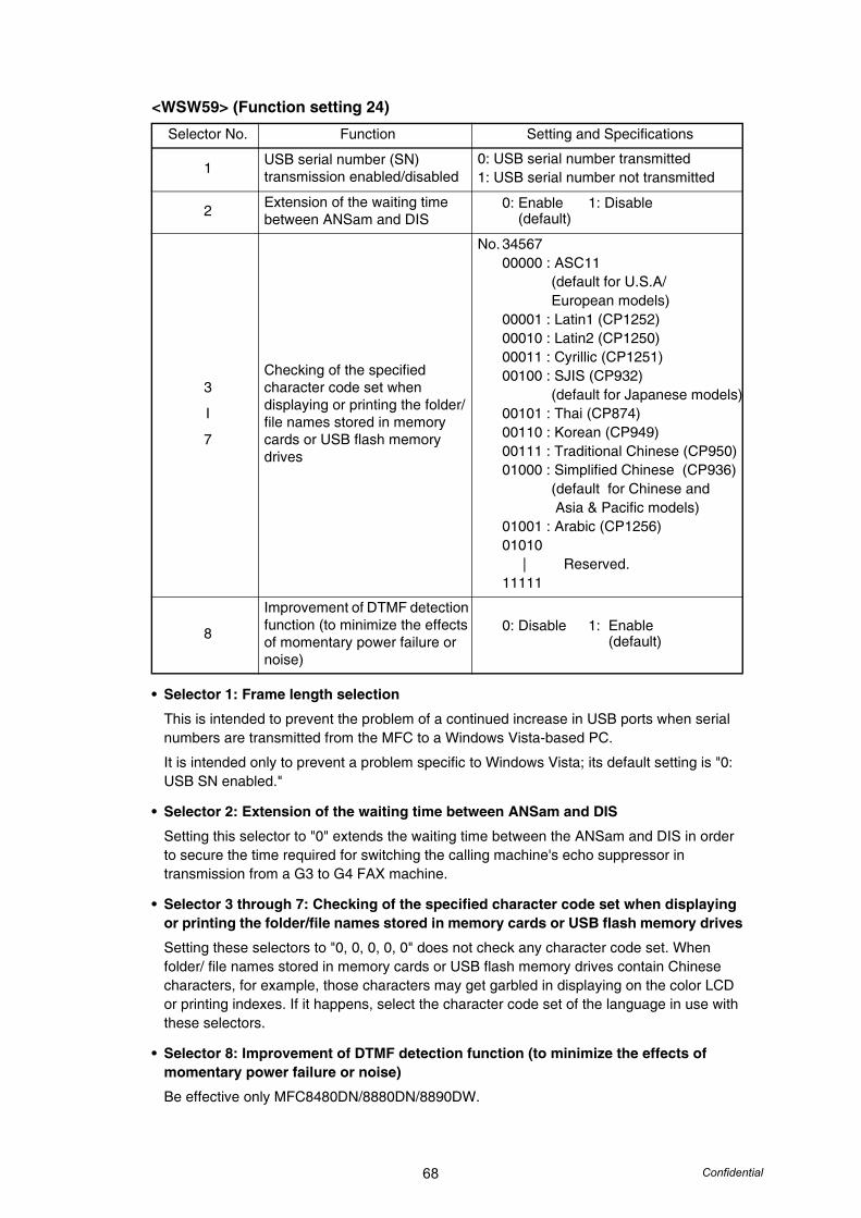
68 Confidential
<WSW59> (Function setting 24)
• Selector 1: Frame length selection
This is intended to prevent the problem of a continued increase in USB ports when serial numbers are transmitted from the MFC to a Windows Vista-based PC.
It is intended only to prevent a problem specific to Windows Vista; its default setting is "0: USB SN enabled."
• Selector 2: Extension of the waiting time between ANSam and DIS
Setting this selector to "0" extends the waiting time between the ANSam and DIS in order to secure the time required for switching the calling machine's echo suppressor in transmission from a G3 to G4 FAX machine.
• Selector 3 through 7: Checking of the specified character code set when displaying or printing the folder/file names stored in memory cards or USB flash memory drives
Setting these selectors to "0, 0, 0, 0, 0" does not check any character code set. When folder/ file names stored in memory cards or USB flash memory drives contain Chinese characters, for example, those characters may get garbled in displaying on the color LCD or printing indexes. If it happens, select the character code set of the language in use with these selectors.
• Selector 8: Improvement of DTMF detection function (to minimize the effects of momentary power failure or noise)
Be effective only MFC8480DN/8880DN/8890DW.
Selector No. Function Setting and Specifications
1 USB serial number (SN) transmission enabled/disabled
0: USB serial number transmitted1: USB serial number not transmitted
2 Extension of the waiting time between ANSam and DIS
0: Enable 1: Disable (default)
3
I
7
Checking of the specified character code set when displaying or printing the folder/file names stored in memory cards or USB flash memory drives
No. 3456700000 : ASC11
(default for U.S.A/ European models)
00001 : Latin1 (CP1252)00010 : Latin2 (CP1250)00011 : Cyrillic (CP1251)00100 : SJIS (CP932)
(default for Japanese models)00101 : Thai (CP874)00110 : Korean (CP949)00111 : Traditional Chinese (CP950)01000 : Simplified Chinese (CP936)
(default for Chinese and Asia & Pacific models)
01001 : Arabic (CP1256)01010
| Reserved.11111
8
Improvement of DTMF detection function (to minimize the effects of momentary power failure or noise)
0: Disable 1: Enable (default)
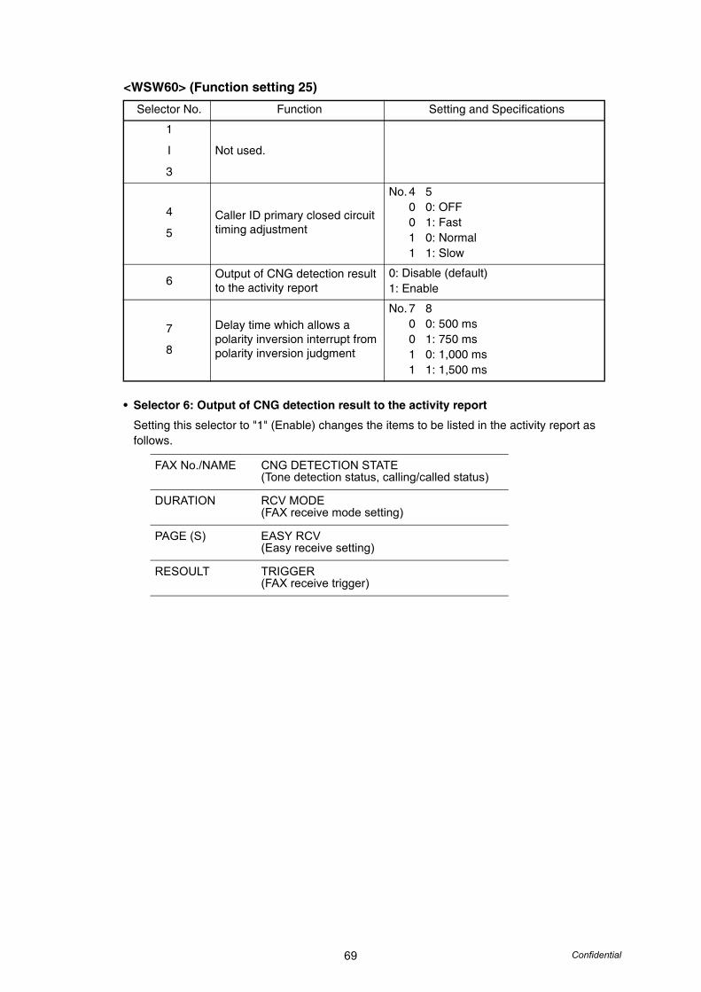
69 Confidential
<WSW60> (Function setting 25)
• Selector 6: Output of CNG detection result to the activity report
Setting this selector to "1" (Enable) changes the items to be listed in the activity report as follows.
Selector No. Function Setting and Specifications
1
I
3
Not used.
4
5Caller ID primary closed circuit timing adjustment
No. 4 50 0: OFF0 1: Fast1 0: Normal1 1: Slow
6 Output of CNG detection result to the activity report
0: Disable (default)1: Enable
7
8
Delay time which allows a polarity inversion interrupt from polarity inversion judgment
No. 7 80 0: 500 ms0 1: 750 ms1 0: 1,000 ms1 1: 1,500 ms
FAX No./NAME CNG DETECTION STATE(Tone detection status, calling/called status)
DURATION RCV MODE(FAX receive mode setting)
PAGE (S) EASY RCV(Easy receive setting)
RESOULT TRIGGER(FAX receive trigger)
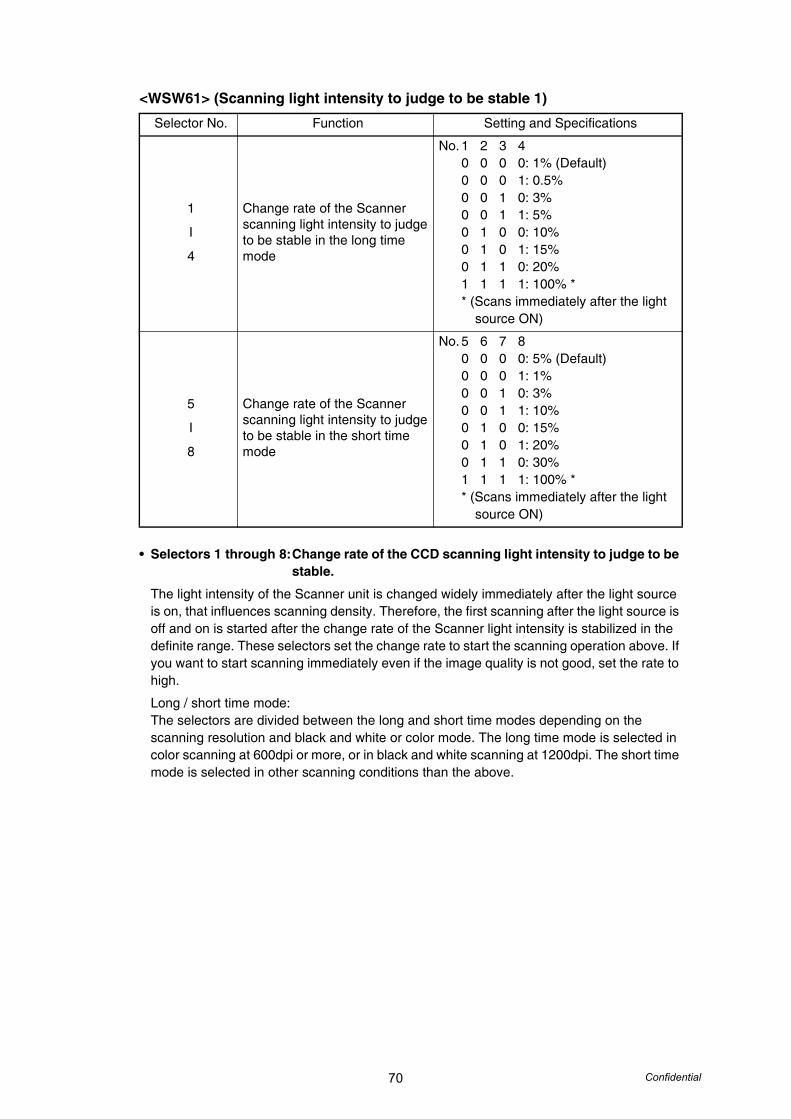
70 Confidential
<WSW61> (Scanning light intensity to judge to be stable 1)
• Selectors 1 through 8:Change rate of the CCD scanning light intensity to judge to be stable.
The light intensity of the Scanner unit is changed widely immediately after the light source is on, that influences scanning density. Therefore, the first scanning after the light source is off and on is started after the change rate of the Scanner light intensity is stabilized in the definite range. These selectors set the change rate to start the scanning operation above. If you want to start scanning immediately even if the image quality is not good, set the rate to high.
Long / short time mode:The selectors are divided between the long and short time modes depending on the scanning resolution and black and white or color mode. The long time mode is selected in color scanning at 600dpi or more, or in black and white scanning at 1200dpi. The short time mode is selected in other scanning conditions than the above.
Selector No. Function Setting and Specifications
1
I
4
Change rate of the Scanner scanning light intensity to judge to be stable in the long time mode
No. 1 2 3 40 0 0 0: 1% (Default)0 0 0 1: 0.5%0 0 1 0: 3%0 0 1 1: 5%0 1 0 0: 10%0 1 0 1: 15%0 1 1 0: 20%1 1 1 1: 100% ** (Scans immediately after the light source ON)
5
I
8
Change rate of the Scanner scanning light intensity to judge to be stable in the short time mode
No. 5 6 7 80 0 0 0: 5% (Default)0 0 0 1: 1%0 0 1 0: 3%0 0 1 1: 10%0 1 0 0: 15%0 1 0 1: 20%0 1 1 0: 30%1 1 1 1: 100% ** (Scans immediately after the light source ON)
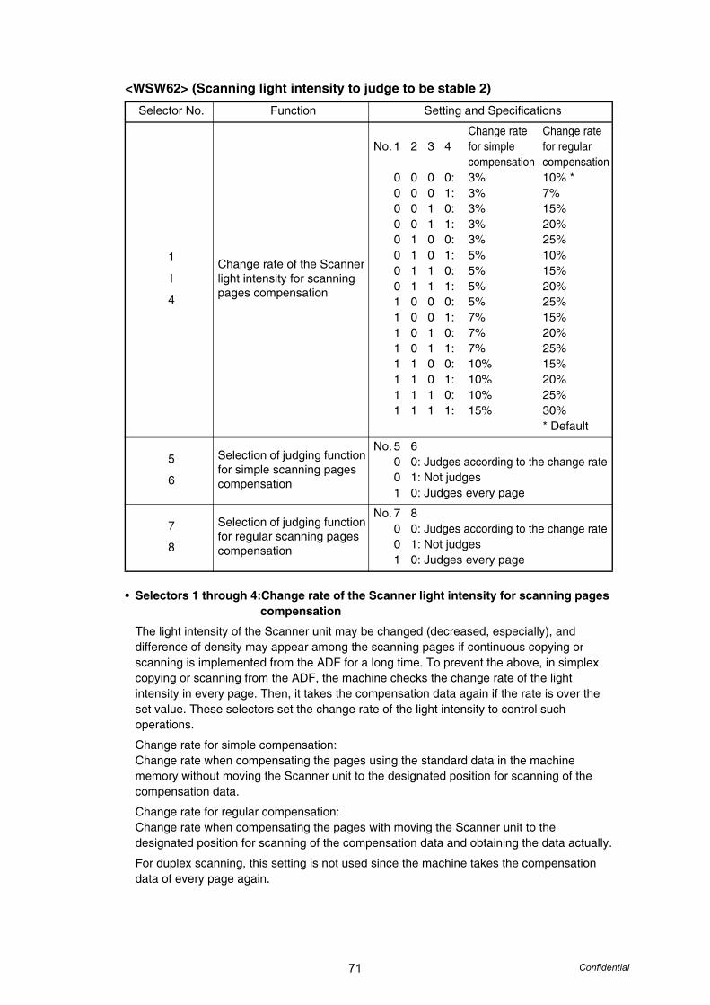
71 Confidential
<WSW62> (Scanning light intensity to judge to be stable 2)
• Selectors 1 through 4:Change rate of the Scanner light intensity for scanning pages compensation
The light intensity of the Scanner unit may be changed (decreased, especially), and difference of density may appear among the scanning pages if continuous copying or scanning is implemented from the ADF for a long time. To prevent the above, in simplex copying or scanning from the ADF, the machine checks the change rate of the light intensity in every page. Then, it takes the compensation data again if the rate is over the set value. These selectors set the change rate of the light intensity to control such operations.
Change rate for simple compensation:Change rate when compensating the pages using the standard data in the machine memory without moving the Scanner unit to the designated position for scanning of the compensation data.
Change rate for regular compensation:Change rate when compensating the pages with moving the Scanner unit to the designated position for scanning of the compensation data and obtaining the data actually.
For duplex scanning, this setting is not used since the machine takes the compensation data of every page again.
Selector No. Function Setting and Specifications
1
I
4
Change rate of the Scanner light intensity for scanning pages compensation
Change rate Change rateNo. 1 2 3 4 for simple for regular
compensation compensation0 0 0 0: 3% 10% *0 0 0 1: 3% 7%0 0 1 0: 3% 15%0 0 1 1: 3% 20%0 1 0 0: 3% 25%0 1 0 1: 5% 10%0 1 1 0: 5% 15%0 1 1 1: 5% 20%1 0 0 0: 5% 25%1 0 0 1: 7% 15%1 0 1 0: 7% 20%1 0 1 1: 7% 25%1 1 0 0: 10% 15%1 1 0 1: 10% 20%1 1 1 0: 10% 25%1 1 1 1: 15% 30%
* Default
5
6
Selection of judging function for simple scanning pages compensation
No. 5 60 0: Judges according to the change rate0 1: Not judges1 0: Judges every page
7
8
Selection of judging function for regular scanning pages compensation
No. 7 80 0: Judges according to the change rate0 1: Not judges1 0: Judges every page
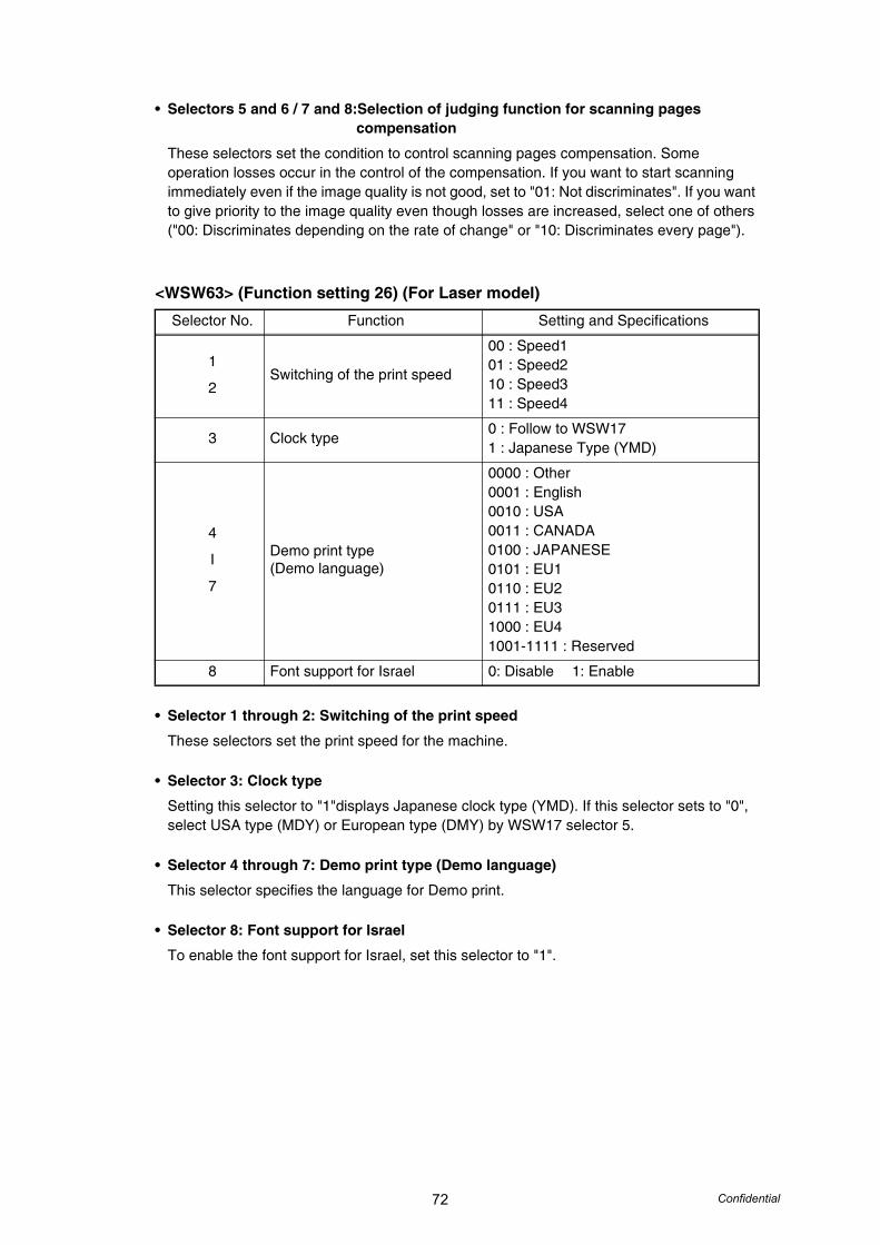
72 Confidential
• Selectors 5 and 6 / 7 and 8:Selection of judging function for scanning pages compensation
These selectors set the condition to control scanning pages compensation. Some operation losses occur in the control of the compensation. If you want to start scanning immediately even if the image quality is not good, set to "01: Not discriminates". If you want to give priority to the image quality even though losses are increased, select one of others ("00: Discriminates depending on the rate of change" or "10: Discriminates every page").
<WSW63> (Function setting 26) (For Laser model)
• Selector 1 through 2: Switching of the print speed
These selectors set the print speed for the machine.
• Selector 3: Clock type
Setting this selector to "1"displays Japanese clock type (YMD). If this selector sets to "0", select USA type (MDY) or European type (DMY) by WSW17 selector 5.
• Selector 4 through 7: Demo print type (Demo language)
This selector specifies the language for Demo print.
• Selector 8: Font support for Israel
To enable the font support for Israel, set this selector to "1".
Selector No. Function Setting and Specifications
1
2Switching of the print speed
00 : Speed101 : Speed210 : Speed311 : Speed4
3 Clock type0 : Follow to WSW171 : Japanese Type (YMD)
4
I
7
Demo print type (Demo language)
0000 : Other0001 : English0010 : USA0011 : CANADA0100 : JAPANESE0101 : EU10110 : EU20111 : EU31000 : EU41001-1111 : Reserved
8 Font support for Israel 0: Disable 1: Enable
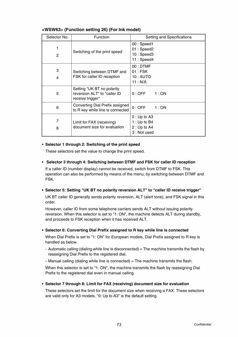
73 Confidential
<WSW63> (Function setting 26) (For Ink model)
• Selector 1 through 2: Switching of the print speed
These selectors set the value to change the print speed.
• Selector 3 through 4: Switching between DTMF and FSK for caller ID reception
If a caller ID (number display) cannot be received, switch from DTMF to FSK. This operation can also be performed by means of the menu, by switching between DTMF and FSK.
• Selector 5: Setting "UK BT no polarity reversion ALT" to "caller ID receive trigger"
UK BT caller ID generally sends polarity reversion, ALT (alert tone), and FSK signal in this order.
However, caller ID from some telephone carriers sends ALT without issuing polarity reversion. When this selector is set to "1: ON", the machine detects ALT during standby, and proceeds to FSK reception when it has received ALT.
• Selector 6: Converting Dial Prefix assigned to R key while line is connected
When Dial Prefix is set to "1: ON" for European models, Dial Prefix assigned to R key is handled as below.
- Automatic calling (dialing while line is disconnected) = The machine transmits the flash by reassigning Dial Prefix to the registered dial.
- Manual calling (dialing while line is connected) = The machine transmits the flash.
When this selector is set to "1: ON", the machine transmits the flash by reassigning Dial Prefix to the registered dial even in manual calling.
• Selector 7 through 8: Limit for FAX (receiving) document size for evaluation
These selectors set the limit for the document size when receiving a FAX. These selectors are valid only for A3 models. "0: Up to A3" is the default setting.
Selector No. Function Setting and Specifications
1
2Switching of the print speed
00 : Speed101 : Speed210 : Speed311 : Speed4
3
4Switching between DTMF andFSK for caller ID reception
00 : DTMF01 : FSK10 : AUTO11 : N/A
5Setting "UK BT no polarity reversion ALT" to "caller ID receive trigger"
0 : OFF 1 : ON
6 Converting Dial Prefix assigned to R key while line is connected 0 : OFF 1 : ON
7
8Limit for FAX (receiving) document size for evaluation
0 : Up to A31 : Up to B42 : Up to A43 : Not used
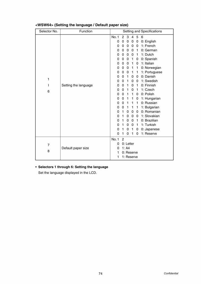
74 Confidential
<WSW64> (Setting the language / Default paper size)
• Selectors 1 through 6: Setting the language
Set the language displayed in the LCD.
Selector No. Function Setting and Specifications
1
I
6
Setting the language
No. 1 2 3 4 5 60 0 0 0 0 0: English0 0 0 0 0 1: French0 0 0 0 1 0: German0 0 0 0 1 1: Dutch0 0 0 1 0 0: Spanish0 0 0 1 0 1: Italian0 0 0 1 1 0: Norwegian0 0 0 1 1 1: Portuguese0 0 1 0 0 0: Danish0 0 1 0 0 1: Swedish0 0 1 0 1 0: Finnish0 0 1 0 1 1: Czech0 0 1 1 0 0: Polish0 0 1 1 0 1: Hungarian0 0 1 1 1 0: Russian0 0 1 1 1 1: Bulgarian0 1 0 0 0 0: Romanian0 1 0 0 0 1: Slovakian0 1 0 0 1 0: Brazilian0 1 0 0 1 1: Turkish0 1 0 1 0 0: Japanese0 1 0 1 0 1: Reserve
7
8Default paper size
No. 1 20 0: Letter0 1: A41 0: Reserve1 1: Reserve
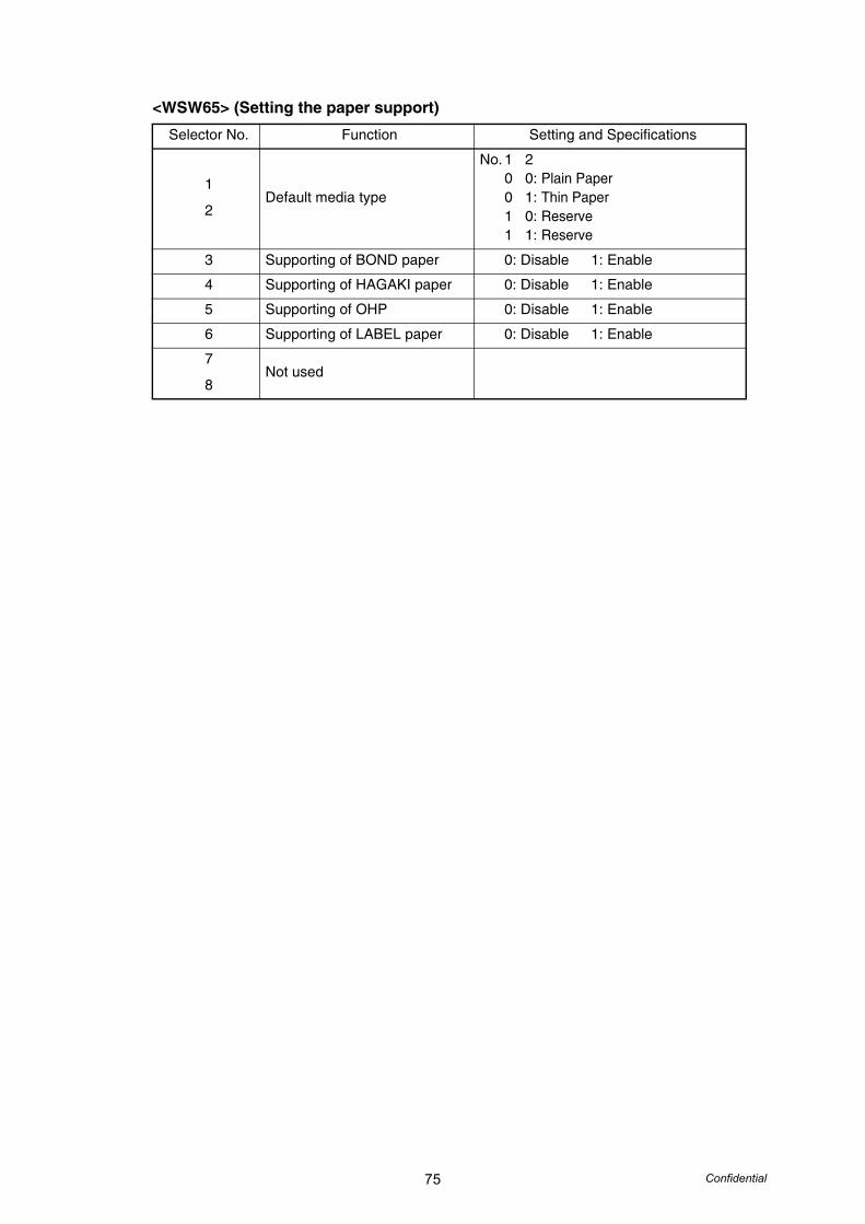
75 Confidential
<WSW65> (Setting the paper support)
Selector No. Function Setting and Specifications
1
2Default media type
No. 1 20 0: Plain Paper0 1: Thin Paper1 0: Reserve1 1: Reserve
3 Supporting of BOND paper 0: Disable 1: Enable
4 Supporting of HAGAKI paper 0: Disable 1: Enable
5 Supporting of OHP 0: Disable 1: Enable
6 Supporting of LABEL paper 0: Disable 1: Enable
7
8Not used
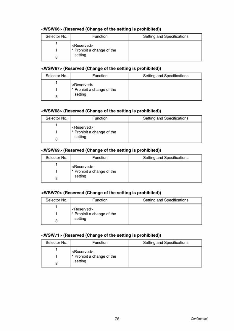
76 Confidential
<WSW66> (Reserved (Change of the setting is prohibited))
<WSW67> (Reserved (Change of the setting is prohibited))
<WSW68> (Reserved (Change of the setting is prohibited))
<WSW69> (Reserved (Change of the setting is prohibited))
<WSW70> (Reserved (Change of the setting is prohibited))
<WSW71> (Reserved (Change of the setting is prohibited))
Selector No. Function Setting and Specifications
1
I
8
<Reserved>* Prohibit a change of the
setting
Selector No. Function Setting and Specifications
1
I
8
<Reserved>* Prohibit a change of the
setting
Selector No. Function Setting and Specifications
1
I
8
<Reserved>* Prohibit a change of the
setting
Selector No. Function Setting and Specifications
1
I
8
<Reserved>* Prohibit a change of the
setting
Selector No. Function Setting and Specifications
1
I
8
<Reserved>* Prohibit a change of the
setting
Selector No. Function Setting and Specifications
1
I
8
<Reserved>* Prohibit a change of the
setting

77 Confidential
<WSW72> (Reserved (Change of the setting is prohibited))
<WSW73> (Reserved (Change of the setting is prohibited))
<WSW74> (ADF stop control)
• Selectors 1 through 8:The limited number of the documents in order for paper ejection of the simplex scanning from ADF
These selectors are used to set the limited number of the paper ejection under the following condition.
- The machine takes action simplex scanning from the ADF.
- The documents which are stacked on the ADF are ejected in order of the documents which has been scanned.
There is a possibility that loading problem or dog-ear problem occurs if the limited number is over a maximum number which machine can paper feeding.
Selector No. Function Setting and Specifications
1
I
8
<Reserved>* Prohibit a change of the
setting
Selector No. Function Setting and Specifications
1
I
8
<Reserved>* Prohibit a change of the
setting
Selector No. Function Setting and Specifications
1
I
8
The limited number of the documents in order for paper ejection of the simplex scanning from ADF
No. 1 2 3 4 5 6 7 80 0 0 0 0 0 0 0: 00 0 0 0 0 0 0 1: 10 0 0 0 0 0 1 0: 20 0 0 0 0 0 1 1: 30 0 0 0 0 1 0 0: 4
|0 1 1 0 0 0 1 1: 990 1 1 0 0 1 0 0 or later: Invalidity

78 Confidential
<WSW75> (Paper ejecting distance of the switch back)
• Selector 1: Adjustment for the paper feeding distance for turning the document counter when the machine takes action duplex scanning
This selector is used to adjust the timing that the switch back roller is turned counter (the paper feeding distance for the document which has already passed through the switch back sensor) after scanning the first page when the machine takes action duplex scanning from ADF by using selectors from 2 to 8.
It is available to choose the direction "+" or "-" from the standard position of the paper feeding distance for the document which you have selected by using selectors from 2 to 8.
• Selectors 2 through 8: Paper feeding parameter for turning the document counter when the machine takes action duplex scanning
These selectors are used to adjust the paper feeding distance from the standard position that the timing of the switch back roller is turned counter after scanning the first page when the machine takes action duplex scanning from ADF. The value is parameter, so it is not actual.
Selector No. Function Setting and Specifications
1
Adjustment for the paper feeding distance for turning the document counter when the machine takes action duplex scanning
0: +1: -
2
I
8
Paper feeding parameter for turning the document counter when the machine takes action duplex scanning
No. 2 3 4 5 6 7 80 0 0 0 0 0 0: 00 0 0 0 0 0 1: 10 0 0 0 0 1 0: 2
|1 1 1 1 1 1 1: 127
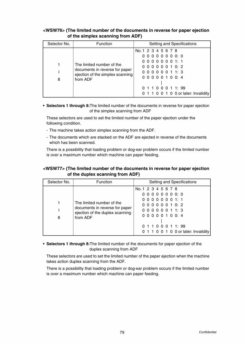
79 Confidential
<WSW76> (The limited number of the documents in reverse for paper ejection of the simplex scanning from ADF)
• Selectors 1 through 8:The limited number of the documents in reverse for paper ejection of the simplex scanning from ADF
These selectors are used to set the limited number of the paper ejection under the following condition.
- The machine takes action simplex scanning from the ADF.
- The documents which are stacked on the ADF are ejected in reverse of the documents which has been scanned.
There is a possibility that loading problem or dog-ear problem occurs if the limited number is over a maximum number which machine can paper feeding.
<WSW77> (The limited number of the documents in reverse for paper ejection of the duplex scanning from ADF)
• Selectors 1 through 8:The limited number of the documents for paper ejection of the duplex scanning from ADF
These selectors are used to set the limited number of the paper ejection when the machine takes action duplex scanning from the ADF.
There is a possibility that loading problem or dog-ear problem occurs if the limited number is over a maximum number which machine can paper feeding.
Selector No. Function Setting and Specifications
1
I
8
The limited number of the documents in reverse for paper ejection of the simplex scanning from ADF
No. 1 2 3 4 5 6 7 80 0 0 0 0 0 0 0: 00 0 0 0 0 0 0 1: 10 0 0 0 0 0 1 0: 20 0 0 0 0 0 1 1: 30 0 0 0 0 1 0 0: 4
|0 1 1 0 0 0 1 1: 990 1 1 0 0 1 0 0 or later: Invalidity
Selector No. Function Setting and Specifications
1
I
8
The limited number of the documents in reverse for paper ejection of the duplex scanning from ADF
No. 1 2 3 4 5 6 7 80 0 0 0 0 0 0 0: 00 0 0 0 0 0 0 1: 10 0 0 0 0 0 1 0: 20 0 0 0 0 0 1 1: 30 0 0 0 0 1 0 0: 4
|0 1 1 0 0 0 1 1: 990 1 1 0 0 1 0 0 or later: Invalidity
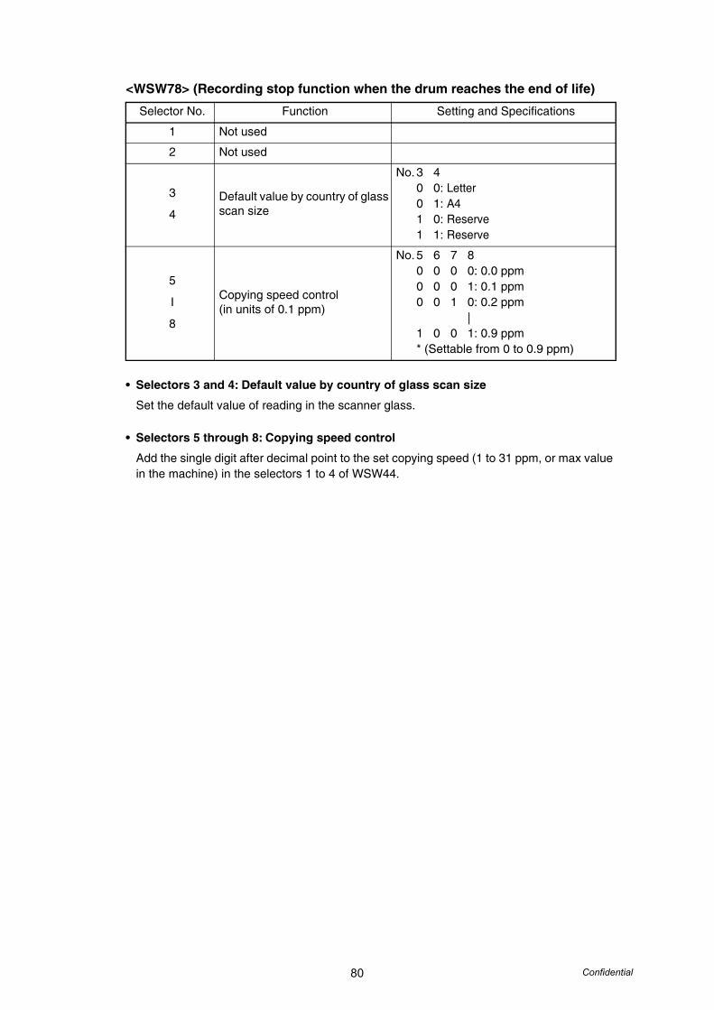
80 Confidential
<WSW78> (Recording stop function when the drum reaches the end of life)
• Selectors 3 and 4: Default value by country of glass scan size
Set the default value of reading in the scanner glass.
• Selectors 5 through 8: Copying speed control
Add the single digit after decimal point to the set copying speed (1 to 31 ppm, or max value in the machine) in the selectors 1 to 4 of WSW44.
Selector No. Function Setting and Specifications
1 Not used
2 Not used
3
4Default value by country of glass scan size
No. 3 40 0: Letter0 1: A41 0: Reserve1 1: Reserve
5
I
8
Copying speed control(in units of 0.1 ppm)
No. 5 6 7 80 0 0 0: 0.0 ppm0 0 0 1: 0.1 ppm0 0 1 0: 0.2 ppm
|1 0 0 1: 0.9 ppm* (Settable from 0 to 0.9 ppm)
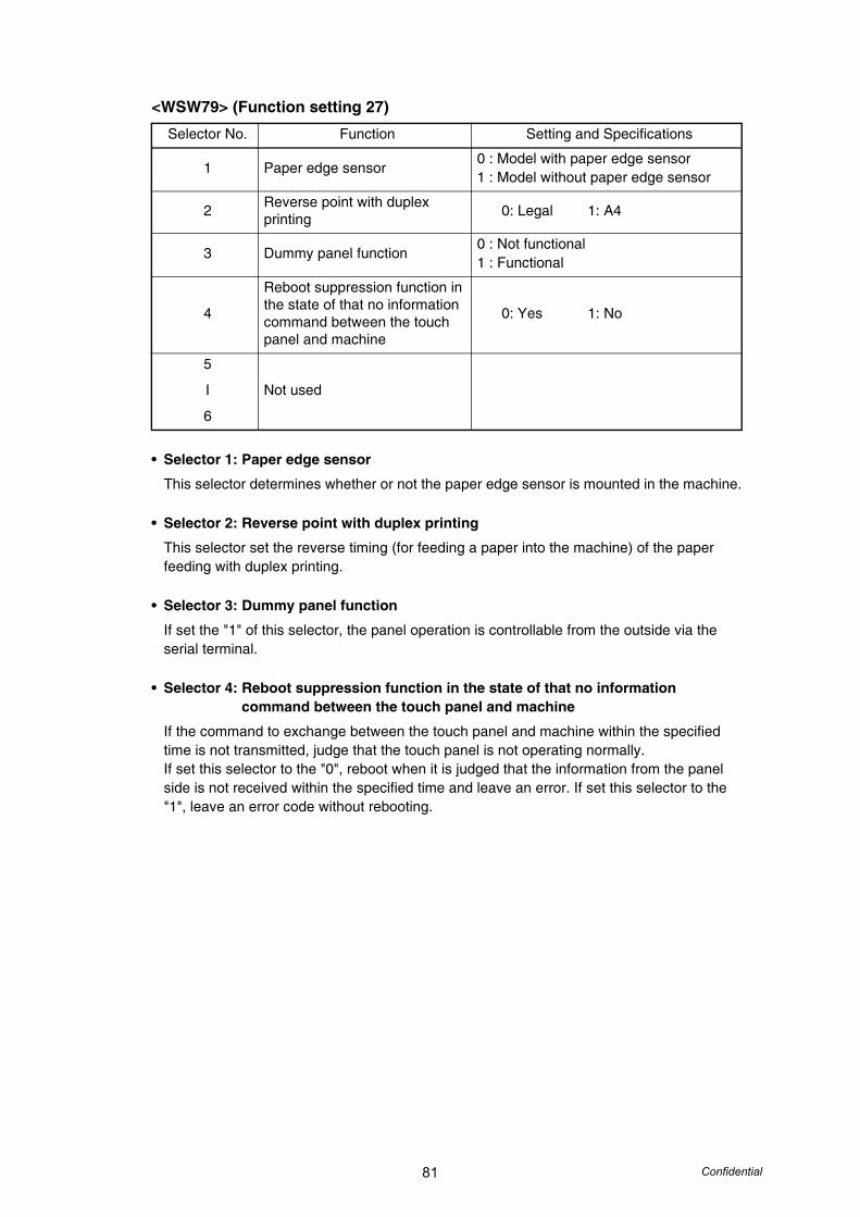
81 Confidential
<WSW79> (Function setting 27)
• Selector 1: Paper edge sensor
This selector determines whether or not the paper edge sensor is mounted in the machine.
• Selector 2: Reverse point with duplex printing
This selector set the reverse timing (for feeding a paper into the machine) of the paper feeding with duplex printing.
• Selector 3: Dummy panel function
If set the "1" of this selector, the panel operation is controllable from the outside via the serial terminal.
• Selector 4: Reboot suppression function in the state of that no information command between the touch panel and machine
If the command to exchange between the touch panel and machine within the specified time is not transmitted, judge that the touch panel is not operating normally.If set this selector to the "0", reboot when it is judged that the information from the panel side is not received within the specified time and leave an error. If set this selector to the "1", leave an error code without rebooting.
Selector No. Function Setting and Specifications
1 Paper edge sensor0 : Model with paper edge sensor1 : Model without paper edge sensor
2 Reverse point with duplex printing 0: Legal 1: A4
3 Dummy panel function0 : Not functional1 : Functional
4
Reboot suppression function in the state of that no information command between the touch panel and machine
0: Yes 1: No
5
I
6
Not used
Related Documents