COMBIMASTER MICROMASTER Integrated COMBIMASTER and MICROMASTER Integrated Reference Manual 1999

Welcome message from author
This document is posted to help you gain knowledge. Please leave a comment to let me know what you think about it! Share it to your friends and learn new things together.
Transcript
COM
BIM
ASTE
RM
ICRO
MAS
TER
Inte
grat
ed
COMBIMASTER andMICROMASTER Integrated
Reference Manual 1999

COMBIMASTER & MICROMASTER IntegratedREFERENCE MANUAL
© Siemens plc. 1999 | G85139-H1731-U300-D2 1
CONTENTS
1. Safety and CE Compliance 3
2. Overview 7
3. Mechanical Installation 93.1 Mechanical Installation I COMBIMASTER .............................................................................9
3.2 Mechanical Installation I MICROMASTER Integrated..........................................................10
4. Electrical Installation 114.1 General Wiring Guidelines....................................................................................................11
4.2 Electrical Installation I MICROMASTER Integrated..............................................................11
4.3 Electrical Installation I COMBIMASTER and MICROMASTER Integrated...........................12
4.4 Mains Cable Connections.....................................................................................................12
4.5 Control Cable Connections...................................................................................................15
5. Operating Information 175.1 General .................................................................................................................................17
5.2 Basic Operation ....................................................................................................................17
5.3 Operation – External Analogue Control................................................................................18
5.4 Operation – Digital Control ...................................................................................................18
5.5 Stopping the Motor................................................................................................................19
5.6 If the Motor Does Not Start Up .............................................................................................19
5.7 Local and Remote Control ....................................................................................................19
5.8 Closed Loop Control .............................................................................................................20
6. System Parameters 216.1 System Parameters Table ....................................................................................................21
6.2 Fault Codes...........................................................................................................................39
7. Options and Accessories 417.1 Clear Text Display Module (OPm2)......................................................................................41
7.2 Profibus CB155....................................................................................................................43
7.3 Control and Commissioning with SIMOVIS ..........................................................................47
7.4 Brake Options .......................................................................................................................50
7.5 Fan Assembly Options..........................................................................................................51
7.6 Motor Interface Plate Options ...............................................................................................52
8. Specifications 538.1 Mechanical Data – Dimensional Drawings ...........................................................................53
8.2 Electrical Data.......................................................................................................................59
8.3 De-rating Information ............................................................................................................60
8.4 Technical Data - COMBIMASTER.......................................................................................61
8.5 Technical Data - MICROMASTER Integrated .....................................................................63
8.6 Output Current Ratings - MICROMASTER Integrated ........................................................65

COMBIMASTER & MICROMASTER IntegratedREFERENCE MANUAL
© Siemens plc. 1999 | G85139-H1731-U300-D22
9. Supplementary Information 679.1 Application Example .............................................................................................................67
9.2 Motor Interface Plates...........................................................................................................68
9.3 Electro-Magnetic Compatibility (EMC)..................................................................................73
9.4 Environmental Aspects .........................................................................................................74
9.5 Users Parameter Settings.....................................................................................................75
Technical data, selection and ordering data (order numbers), accessories and availability are subjectto change.

COMBIMASTER & MICROMASTER IntegratedREFERENCE MANUAL
© Siemens plc. 1999 | G85139-H1731-U300-D2 3
1. SAFETY AND CE COMPLIANCE
Before installing and operating this equipment read these safety instructions and warningscarefully. Also read and obey all the warning signs attached to the equipment. Make sure that thewarning labels are kept in a legible condition and replace any missing or damaged labels.
WARNING
This equipment must be installed, operated and maintained by suitably qualifiedpersonnel only.
Use only permanently-wired input power connections. The equipment must be grounded(IEC 536 Class 1, NEC and other applicable standards).
Wait at least five minutes after the power has been turned off, before opening theequipment. The dc-link capacitor remains charged to dangerous voltages even when thepower is removed. When working on open equipment, note that live parts are exposedand do not touch these parts.
Some parameter settings can start the motor automatically when power is restored aftera mains failure.
Do not connect machines with a three-phase power supply, fitted with EMC filters, to asupply via an ELCB (Earth Leakage Circuit Breaker - see EN50178, section 6.5).
Obey all general and regional installation and safety regulations relating to work on highvoltage installations, as well as regulations covering correct use of tools and personalprotective equipment.
Note that the following terminals can carry dangerous voltages even when the inverter isstopped:Power supply terminals L1, L2 and L3Motor terminals U, V and W.
When using the analogue input, the jumpers must be correctly set and the analogue inputtype selected (P023) before enabling the analogue input with P006. If this is not done themotor may start inadvertently.
This equipment is capable of providing internal motor overload protection in accordancewith UL508C section 42.
This equipment is suitable for use in a circuit capable of delivering not more than 10,000symmetrical amperes (rms), for a maximum voltage of 240V/480V/500V when protectedby a time delay fuse (see Electrical Data for details).
Do not operate the equipment in direct sunlight.
This equipment must not be used as an ‘emergency stop’ mechanism (see EN 60204,9.2.5.4).

COMBIMASTER & MICROMASTER IntegratedREFERENCE MANUAL
© Siemens plc. 1999 | G85139-H1731-U300-D24
WARNING
Take note of the general and regional installation and safety regulations regarding workon high voltage installations (e.g. VDE). Adhere to relevant regulations regarding correctuse of tools and protective gear.
Use the lifting eyes provided if a motor is to be lifted. Do not lift machine sets bysuspending the individual machines! Always check the capacity of the hoist before liftingany equipment.
Do not paint over the black case finish of the inverter as this will affect the units thermalperformance.
CAUTION
Do not allow children or the general public to access or approach this equipment.
Do not install the inverter where ambient conditions exceed the specified protectionrating. IP ratings: COMBIMASTER – IP55; MICROMASTER Integrated – IP65.
Keep operating instructions within easy reach and give them to all users.
Use this equipment only for the purpose specified by the manufacturer. Do not carry outany modifications, or fit any spare parts which are not sold or recommended by themanufacturer; this could cause fires, electric shock or other injuries.
EUROPEAN LOWVOLTAGE & EMCDIRECTIVES
The COMBIMASTERproduct complies with therequirements of the LowVoltage Directive73/23/EEC and the EMCDirective 89/336/EEC.
The units are certified for compliance withthe following standards:
EN 60204-1 Safety of machinery -Electrical equipment of machines
EN 60146-1-1 Semiconductor converters -General requirements and line commutatedconverters
BS EN50081-2 1995 General EmissionStandard - Industrial Environment
BS EN50082-2 1995 General ImmunityStandard - Industrial Environment.
The MICROMASTER Integrated productcomplies with the requirements of the LowVoltage Directive 73/23/EEC.
The units are certified for compliance withthe following standards:
EN 60204-1 Safety of machinery -Electrical equipment of machines
EN 60146-1-1 Semiconductor converters -General requirements and line commutatedconverters.
EUROPEAN MACHINERY DIRECTIVE
The MICROMASTER Integrated /COMBIMASTER products are suitable forincorporation into machinery.
The MICROMASTER Integrated /COMBIMASTER must not be put intoservice until the machinery into which it isincorporated has been certified to be incompliance with the provisions of theEuropean Directive 89/392/EEC.
Only valid for machinery tobe operated in the EuropeanCommunity.

COMBIMASTER & MICROMASTER IntegratedREFERENCE MANUAL
© Siemens plc. 1999 | G85139-H1731-U300-D2 5
COMBIMASTER – UL CERTIFICATION
UL cUL listed power conversion equipmenttype 5B33 in accordance with UL508C.
For use in pollution degree 2 environment.
(Applies to the Inverter only)
MICROMASTER Integrated – URCERTIFICATION
UR cUR recognised power conversionequipment in accordance with UL508C.
For use in pollution degree 2 environment.
This equipment must be externally cooled bya fan, the rating of which depends on the unitCase Size. For Case Sizes A and B, the fanmust provide 0.42m3/min and 1.25m3/minrespectively.
BSI
R
EGIST ERED
ISO 9001
Siemens plc operates a quality management system which complies with therequirements of ISO 9001.

COMBIMASTER & MICROMASTER integratedREFERENCE MANUAL
© Siemens plc. 1999 | G85139-H1731-U300-D26
Intentionally Left Blank

COMBIMASTER & MICROMASTER IntegratedREFERENCE MANUAL
© Siemens plc. 1999 | G85139-H1731-U300-D2 7
2. OVERVIEW
The COMBIMASTER and MICROMASTERIntegrated (MMI) are integratedmotor/inverters for variable speedapplications.
The inverter is microprocessor controlledand uses state of the art IGBT(InsulatedGate Bipolar Transistor) technology forreliability and flexibility. A special pulse-width modulation method with ultrasonicpulse frequency permits extremely quietmotor operation. Inverter and motorprotection is provided by comprehensiveprotective functions.
Key design features include:
•••• Easy to install and commission.
•••• Closed loop control using a proportional,Integral (PI) control loop function.
•••• High starting torque with programmablestarting boost.
•••• Remote control capability via RS485 seriallink using the USS protocol.
•••• Ability to control up to 31COMBIMASTERS via the USS protocol.
•••• Optional remote control capability viaRS485 serial link using PROFIBUS-DP.
•••• Factory default parameter settings pre-programmed for European and NorthAmerican requirements.
•••• Output frequency (and hence motorspeed) can be controlled by one of fourmethods:
1 Built in potentiometer.
2 High resolution analogue setpoint(voltage or current input).
3 Fixed frequencies via binary inputs.
4 Serial interface.
•••• Built-in dc injection braking.
•••• Acceleration/deceleration times withprogrammable smoothing.
•••• Single signal relay output incorporated.
•••• External connection for optional Clear TextDisplay (OPm2) or for use as externalRS485 interface.
•••• Fast Current Limit (FCL) for reliable trip-free operation.
•••• Optional factory-fitted resistive braking unit–Case Size B only (also available as aseparate post-sale option).
•••• Optional motor brake and interface.
•••• Integral class A or class B filter options.
Reference Literature:
• Variable frequency inverters for AC motorsup to 90kW.– Catalogue DA64 98/99.– E20002-K4064-A101-A2-7600.
• LV three phase motors.– Squirrel Cage Motors catalogue M11-1999.– E20002-K1711-A101-A3-7600.
• MMI Motor Adaptation Guidelines (English)– (Available August 99).– G85139-H1731-U500-A.
• COMBIMASTER & MICROMASTERIntegrated Operating Instructions (English).– 6SE9996-0XA36
• COMBIMASTER & MICROMASTERIntegrated Brake Options OperatingInstructions (English).– G85139-H1731-U450-D1
(Available August 99)

COMBIMASTER & MICROMASTER IntegratedREFERENCE MANUAL
© Siemens plc. 1999 | G85139-H1731-U300-D28
Intentionally Left Blank

COMBIMASTER & MICROMASTER IntegratedREFERENCE MANUAL
© Siemens plc. 1999 | G85139-H1731-U300-D2 9
3. MECHANICAL INSTALLATION
WARNING
Take note of the general and regional installation and safety regulations regarding workon high voltage installations (e.g. VDE). Adhere to relevant regulations regarding correctuse of tools and protective gear.
Use the lifting eyes provided if a motor is to be lifted. Do not lift machine sets bysuspending the individual machines! Always check the capacity of the hoist before liftingany equipment.
Do not paint over the black case finish of the inverter as this will affect the units thermalperformance.
Take suitable precautions to prevent transmission elements from being touched. If theCOMBIMASTER is started up without a transmission element attached, the featherkeymust be secured in position to prevent it from flying off while the shaft is rotating.
3.1 Mechanical Installation I COMBIMASTER
Tighten down screw-in lifting eyes prior tousing the COMBIMASTER.
Stable foundations or mounting conditionsand a well balanced transmission elementare essential for quiet, vibration-freerunning. It may be necessary to balancethe whole rotor and transmission element.
The rotors are dynamically balanced with afull featherkey inserted as standard. Since1991 the type of balance has been markedon the drive end of the shaft (shaft endface). F denotes balanced with fullfeatherkey; H denotes balanced with halffeatherkey. Bear in mind the type ofbalance when fitting the transmissionelement.
Poor running characteristics can arise incases where the transmission elementshave a length ratio of hub length to shaftend length < 0.8 and they run at speedsgreater than 1500 rpm. In such casesrebalancing may be necessary, e.g. byreducing the distance by which thefeatherkey protrudes from the transmissionelement and the shaft surface.
Please check the following prior tocommissioning :
• The rotor turns freely without rubbing.
• The motor is assembled and alignedproperly.
• The transmission elements are adjustedcorrectly (e.g. belt tension) and thetransmission element is suitable for thegiven operating conditions.
• All electrical connections, mounting screwsand connecting elements are tightenedand fitted correctly.
• All protective conductors are installedproperly.
• Any auxiliary equipment that might befitted (e.g. mechanical brake) is in workingorder.
• Protection guards are installed around allmoving and live parts.
• The maximum speed is not exceeded.The maximum speed is the highestoperating speed permitted. Rememberthat motor noise and vibration are worse atthis speed and bearing life is reduced.
• The above list is not meant to beexhaustive - additional checks may also berequired.

COMBIMASTER & MICROMASTER IntegratedREFERENCE MANUAL
© Siemens plc. 1999 | G85139-H1731-U300-D210
3.2 Mechanical Installation I MICROMASTER Integrated
The motor / MICROMASTER Integratedcombination should be installed accordingto guidelines similar to those given for theCOMBIMASTER.
First fit the Motor Interface Plate (MIP) tothe motor. In most cases the MIP makesuse of the existing motor gasket.
Refer to MMI Motor AdaptationGuidelines(Ref. G85139-H1731-U500)
Available August 1999
WARNING
Cooling of the inverter must be provided, either via a cut-out in the motor Fan Cowl or byusing the inverter fan option M41
CS A: 6SE9996-0XA01
CS B: 6SE9996-0XA02

COMBIMASTER & MICROMASTER IntegratedREFERENCE MANUAL
© Siemens plc. 1999 | G85139-H1731-U300-D2 11
4. ELECTRICAL INSTALLATION
WARNING
Take note of the general and regional installation and safety regulations regarding workon high voltage installations (e.g. VDE). Adhere to relevant regulations regarding correctuse of tools and protective gear.
4.1 General Wiring Guidelines
The Case size A (CS A) and Case Size B(CS B) COMBIMASTER is designed tooperate in an industrial environment wherea high level of Electro-MagneticInterference (EMI) can be expected.Usually, good installation practices willensure safe and trouble-free operation.However, if problems are encountered, thefollowing guidelines may prove useful. Inparticular, grounding of the system 0V atthe inverter, as described below, may proveeffective.
1 All equipment must be well earthed usingshort, thick earthing cable connected to acommon star point or busbar. It isparticularly important that any controlequipment connected to the inverter (suchas a PLC) is connected to the same earthor star point as the inverter via a short,thick link. Flat conductors (e.g. metalbrackets) are preferred as they have lowerimpedance at high frequencies.
2 Use screened leads for connections to thecontrol circuitry. Terminate the ends of thecable neatly, ensuring that long strands ofunscreened wire are not left visible.
3 Separate the control cables from thepower connections as much as possible,using separate trunking, etc. If control andpower cables cross, arrange the cables sothat they cross at 90°.
4 Ensure that contactors are suppressed,either with R-C suppressers for ACcontactors or ‘flywheel’ diodes for DCcontactors, fitted to the coils. Varistorsuppressers are also effective.
Safety regulations must not becompromised when installing theCOMBIMASTER or MICROMASTERIntegrated !
4.2 Electrical Installation I MICROMASTER Integrated
The motor wires should be connected ineither star or delta configuration on the MIP(check motor rating plate).
Star Connection
Wire Terminal
U2/V2/W2 NU1 UV1 VW1 W
Delta Connection
Wire Terminal
U1/W2 U
U2/V1 V
V2/W1 W

COMBIMASTER & MICROMASTER IntegratedREFERENCE MANUAL
© Siemens plc. 1999 | G85139-H1731-U300-D212
W
V U
NTB1
W
V U
NTB1
U1
U2
V1
V2
W1
W2
PTCwires
Earth connection
Star connection Delta connection
Earth connection
Figure 1 Motor Wire Connection.
WARNING
It is essential that the MIP is correctly earthed to the motor. This is usually achievedusing a short earth cable connected between the MIP and a suitable connection point onthe motor. Death or severe injury can result if the motor is not correctly earthed.Incorrect earthing can also prevent any MICROMASTER Integrated built-in EMC filterfrom operating correctly.
4.3 Electrical Installation I COMBIMASTER and MICROMASTER Integrated
Procedure
Remove the four cross-head screws on theinverter's cover to access the electricalterminals.
For details of cable sizes, referto the Electrical Data (section8.4) of this document.
A ‘drip loop’ is recommendedwhen connecting the mains andcontrol cables (see Fig. 6).
CAUTION
The printed circuit boards contain CMOS components that are particularly sensitive tostatic electricity. For this reason avoid touching the boards or components with your barehands or metal objects.
4.4 Mains Cable Connections
Ensure that the power source supplies thecorrect voltage and is designed for therated current. Use the appropriate circuit-breakers with the specified current ratingbetween the power supply and inverter.
Use Class 1 60/75oC copper wire only. Usea 4-core screened cable. If crimp terminalsare used they must be insulated. If crimpsare not used, the strip length must notexceed 5mm.
Feed the power cable into the inverter viathe gland hole nearest to the motor shaft.Connect the power leads to terminals L1,L2, L3 (L1, L2 for single phase units) andthe separate earth.
Use a 4 - 5 mm cross-tip screwdriver totighten the terminal screws

COMBIMASTER & MICROMASTER IntegratedREFERENCE MANUAL
© Siemens plc. 1999 | G85139-H1731-U300-D2 13
JP 305 connectsPI- to 0V
Earthconnection
JP 303
Jumpers forPI input typeDefault = V
JP 302
Note: Jumper in 'V' position = voltage input (default)Jumper in 'I' position = current input
V
I
JP 304 connectsAIN- to 0V
JP 301
Jumpers forAnalogue input type
Default = V
JP 300
V
I
Mainsconnection
Control cableconnector(PL800)
OPm2connector(SK200)
LED(green)
LED(yellow)
ControlPotentiometer
(R314)
IMPORTANT
Ensure that the following tightening torques are used:
Access cover retaining screws 4.0 Nm
Gland hole covers 1.0 NM
Main connector screws 1.0 Nm
Earth connection 1.5 Nm.
Figure 2 Electrical Connection (CS B)
Check that the supply voltage iscorrect for the inverter used byreferring to the rating label.
Cable Glands: (Case Size B)
PG21 – MainsPG16 - Signal

COMBIMASTER & MICROMASTER IntegratedREFERENCE MANUAL
© Siemens plc. 1999 | G85139-H1731-U300-D214
Earthconnection
JP 300
Jumpers forAnalogue input type
Default = V
JP 301V
I
JP 304connectsAIN- to 0V
JP 305connectsPI- to 0V
JP 303
Jumpers forPI input typeDefault = V
JP 302
V
I
Mainsconnection
Note: Jumper in 'V' position = voltage input (default)Jumper in 'I' position = current input
Control cable connector(PL700)
OPm2 connector(SK200)
LED(green)
LED(yellow)
Control Potentiometer(R314)
IMPORTANT
Ensure that the following tightening torques are used:
Access cover retaining screws 4.0 Nm
Gland hole covers 1.0 NM
Main connector screws 1.0 Nm
PL700 screws 0.5 Nm
Earth connection 1.5 Nm.
Figure 3 Electrical Connection (CS A)
Check that the supply voltage iscorrect for the inverter used byreferring to the rating label.
Cable Glands : (Case Size A)
PG16 – Mains & Signal

COMBIMASTER & MICROMASTER IntegratedREFERENCE MANUAL
© Siemens plc. 1999 | G85139-H1731-U300-D2 15
4.5 Control Cable Connections
CAUTION
The control and power supply cables must be laid separately. They must not be fed throughthe same cable conduit / trunking.
Use screened cable for the control lead.
Feed the control cable into the inverter viathe appropriate gland hole. Connect thecontrol wires in accordance with theinformation in Figures 4, 5 and 6, having firstunplugged connector block PL800 from thePCB (CS B only).
IMPORTANT: A wire link must be fittedbetween control terminals 5 (DIN1) and 1(P10+) if it is required to start the inverterfrom the control potentiometer R314, or theanalogue input.. The wire link must beremoved when operation via a run/stopswitch is required.
COMBIMASTER Control TerminalCabling Information
CS A (PL700): CS B (PL800)
Cable AWG 22 – 18 28 – 20
= approx. mm2 0.35 – 0.82 0.08 – 0.50
Strip Length (mm) 5 – 6 5 – 6
Strip Length (inch) 0.22 0.22
Note that the optionalpotentiometer fitted as ananalogue set point shown inFigure 4 & 5 assumes thatjumper JP304 is connecting 0V(pin 2) to AIN- (pin 4).
+15V can be used as analternative to P10+ for thedigital inputs.
Plug the connector block back into the PCB(CS B only), refit the cover and tighten thefour securing screws.
12 11 10 9 8 7 6 5
5
44
3
3
22
1
1
PI+ PI- +15V
JP305 JP304
1 - +5V (250mA max.)2 - N (-)3 - 0V4 - P (+)5 - no connection
PI Power Supply(+15V,
max. 50mA)
PI +ve Input(0 - 10V
or 0 - 20mA)
RLB(NO)
RLC(COM)
Relay (RL1)(30V dc. 1.0 A max.)
Digital Inputs(7.5 - 33V, max. 5mA)
PL800 (CS B) / PL700 (CS A) SK200 Socket
DIN3 DIN2 DIN1 AIN- AIN+ 0V P10+
Analogue Input(0/2 - 10V,
or 0/4 - 20mA)
Power Supplyfor Digital and
AnalogueInputs
(+10V, max. 10mA)
PI -ve Input
Figure 4 Control Terminal Connections

COMBIMASTER & MICROMASTER IntegratedREFERENCE MANUAL
© Siemens plc. 1999 | G85139-H1731-U300-D216
1.8mm max. screwdriver
Figure 6 Cable Connections with Drip Loop
3 ~
M
C PU
A /D
SI
G R
ZK
W R
A/D Analogue to Digital ConverterCPU MicroprocessorGR RectifierM MotorRS485 Serial InterfaceSI Mains FuseWR InverterZK DC Link Capacitor
2
3
4
5
6
3
1
2
PE
Nominal:1/3 AC 208-240V3 AC 380 - 500 V
L1, L2, L3
PEU, V, W
1P10+ (10 m A ) m ax.)
0V
PE
4
-
+
24 V
OR
ORV :0-10 V2-10 V
I: 0-20m A4-20m A
A IN +
A IN -
D IN 1
D IN 2
PE
+5V
N(-)
PL700 CS APL800 CS B
SK200
0V
P(+)
11
12
8
9
Power supply for PIfeedback transduceror other load
~
3 ~
RLBRLC
RS485
RelayConnections
Connections forSerial Link or OPm2
7D IN 3
+15V
10
PI-
PI+
Figure 7 Block Diagram
Figure 5 Connecting Control Wires to PL800

COMBIMASTER & MICROMASTER IntegratedREFERENCE MANUAL
© Siemens plc. 1999 | G85139-H1731-U300-D2 17
5. OPERATING INFORMATION
WARNING
The equipment must not be switched on until after its cover has been fitted and the coverscrews have been tightened to the correct torque.
After the power has been turned off, you must always wait five minutes so that the dc linkcapacitors can discharge. Do not remove the cover until this time has elapsed.
All settings must only be entered by qualified personnel, paying particular attention to thesafety precautions and warnings.
5.1 General
For basic operation of COMBIMASTER &MICROMASTER Integrated, no additionalequipment is required. However, for morecomplex operation, Opm2 – Clear TextDisplay is required (Opm2 is available asan option, but must be ordered separately).
The inverter does not have a mains powerswitch and is therefore live when the mainssupply is connected.
When delivered, the inverter has a frequencysetpoint range of between 0 Hz and 50 Hz.Regardless of its initial position, internalpotentiometer R314 must be turned fullycounter-clockwise before it can be used tostart the COMBIMASTER.
R314 can be accessed by removing theright-hand gland hole cover (see Fig. 2 &3).
Connecting a serial link or the OPm2 to theserial interface is made using the circularconnector SK200 (see fig. 2 & 3)
Parameter settings can only be changed byusing either the serial interface (SK200) oran optional Clear Text Display (OPm2).Refer to the parameter list section in thisdocument for a full description of eachavailable parameter.
Analogue input type is selected by jumpersJP300 and JP301. JP300 closed selectscurrent input, JP301 closed (default) selectsvoltage input. These jumpers can only beaccessed when the cover is removed (seeFig. 2 & 3).
If the motor is run unloaded(e.g. for test purposes) andvibration or trip conditionsoccur, change P077 from 0 to3 (requires OPm2).
5.2 Basic Operation
There are two basic modes of operation forthe inverter.
1 Using the internal potentiometer only:
a For forward rotation, ensure that alink is fitted between DIN1 (pin 5)and P10+ (pin 1) on PL800/PL700(see Fig. 4). For reverse rotation,connect the link to DIN2 (pin 6)instead of DIN1.
b Apply mains power. The green andyellow LEDs will illuminate to showthat power is applied. Turnpotentiometer R314 fully counter-
clockwise. Turn the potentiometerclockwise until the yellow LEDextinguishes. This indicates thatpower is now applied to the motor.Continue turning clockwise toincrease the speed of the motor.
c Turn the potentiometer counter-clockwise to reduce the speed ofthe motor. Turning thepotentiometer fully counter-clockwise causes the motor to slowto a complete stop. Check that bothLEDs are illuminated (STANDBYmode).

COMBIMASTER & MICROMASTER IntegratedREFERENCE MANUAL
© Siemens plc. 1999 | G85139-H1731-U300-D218
2 Using a combination of the internalpotentiometer and a run/stop switch:
a Connect a run/stop switch betweenDIN1 (pin 5) and P10+ (pin 1) onPL700 (see Fig. 4) if forwardrotation is required. If reverserotation is required instead, connectthe switch to DIN2 (pin 6) instead ofDIN1 (pin 5).
IMPORTANT: Remove the link, if fitted,between pins 5 and 1 before the run/stopswitch is fitted.
b Apply mains power. The green andyellow LEDs will illuminate to show thatpower is applied.
c Set the external run/stop switch to ON.
d Turn potentiometer R314 clockwise toset the required motor speed.
e Stop the motor by setting the externalon/off switch to OFF. When the switch isset to ON again, it will run at the speedpreviously set using the potentiometer.
5.3 Operation – External Analogue Control
1 Connect a 4.7 kΩ potentiometer to thecontrol terminals as shown in Fig.4 orapply a 0 - 10 V signal between pin 2(0V) and pin 3 (AIN+). In both cases,position jumper JP304 to connect 0V toAIN-.
2 Ensure that a link is fitted between pin 5(DIN1) and pin 1 (P10+).
3 Check that voltage input is selected byensuring that the jumper is fitted toJP301.
4 Refit the cover, tighten the coverscrews to the correct torque and thenapply mains power to the inverter.
5 Turn the external potentiometer (oradjust the analogue control voltage)until the desired frequency is achieved.The unit will not switch on until aminimum of 2 V has been applied.
The frequency set by theexternal voltage is added tothe frequency set by theinternal potentiometer. Refer toParameter P331 , Section 6.
As with Basic Operation, a run/stop switchcan be used to start and stop the motor, orthe direction of rotation can be changed byconnecting the link to DIN2 instead of DIN1.
5.4 Operation – Digital Control
This method of operation requires either aClear Text Display (OPm2) or a serial linkconnection. The use of the Clear TextDisplay module is described in the Optionssection of this document. For a basic start-up configuration using digital control,proceed as follows:
1 Remove the link that connects controlterminal 5 to terminal 1 (if one has beenfitted).
2 Connect control terminal 5 to terminal 1via a simple on/off switch. This sets upthe inverter for clockwise rotation(default). If counter-clockwise operationis required, connect a switch betweencontrol terminals 6 and 1.
3 Connect the OPm2 or serial link toSK200. Refit the cover, tighten thecover screws to the correct torque andthen apply mains power to the inverter.
4 Set parameter P006 to 0 to specifydigital setpoint(see Section 6).
5 Set parameter P005 to the desiredfrequency setpoint.
6 Set the external on/off switch to ON orpress the ON button on the OPm2 (setP007 = 001 to use the OPm2). Theinverter will now run at the frequencyset by P005.

COMBIMASTER & MICROMASTER IntegratedREFERENCE MANUAL
© Siemens plc. 1999 | G85139-H1731-U300-D2 19
5.5 Stopping the Motor
Via the external on/off switch:
Setting the switch to OFF overrides thesetting on the potentiometer and causes themotor to come to a controlled stop.
Via the potentiometer:
Turning the potentiometer counter-clockwise until the input voltage dropsbelow 2 V causes the motor to slow to astop. If an external potentiometer isapplied, the input voltage must also bebelow 2V to stop.
5.6 If the Motor Does Not Start Up
Check the LEDs on the side of the inverter:
LED State COMBIMASTER / MICROMASTER Integrated Status
Green Yellow
ON ON Mains power on, inverter not running (STANDBY)ON OFF Inverter running, as per control commands (ON)Flashing Flashing Current limit warningFlashing ON Inverter overtemperatureON Flashing Motor overtemperatureOFF ON Other fault (e.g. tripped)OFF Flashing Mains undervoltageOFF OFF Mains supply fault (e.g. faulty external switch)
If a fault occurs:
Switch off, disconnect and then reconnectthe power, and then switch on again.Switch off if the fault condition persists.Trips can be reset by using DIN3.
If a warning occurs:
Switch off, disconnect and reconnect thepower and then switch on again.
If the fault/warning persists, furtherinvestigation requires an OPm2 or a seriallink connection.
5.7 Local and Remote Control
The inverter can be controlled either locally(default), or remotely via a USS data lineconnected to the RS485 connector(SK200).
When local control is used (P910 = 0), themotor can only be controlled via the internalpotentiometer or the control terminals.Control commands, setpoints or parameterchanges received via the RS485 interfacehave no effect.
For remote control, the serial interface isdesigned as a 2-wire connection for bi-directional data transmission. Refer toparameter P910 in System Parameters forthe available remote control options.
When operating via remote control theinverter will not accept control commandsfrom the terminals. Exception: OFF2 orOFF3 can be activated via parameter P051to P053 (refer to parameters P051 to P053in System Parameters).
31 COMBIMASTERS can be connected toan external control unit at the same timeand can be addressed individually.

COMBIMASTER & MICROMASTER IntegratedREFERENCE MANUAL
© Siemens plc. 1999 | G85139-H1731-U300-D220
5.8 Closed Loop Control
Closed loop control is only possible when anOPm2 or a serial link is connected to theCOMBIMASTER.
5.8.1 General Description
The COMBIMASTER provides aProportional/Integral (PI) control function forclosed loop control (see Figure 8). PI control isideal for temperature or pressure control, orother applications where the controlled variablechanges slowly or where transient errors arenot critical. This control loop is not suitable foruse in systems where fast response times arerequired.
Note: The closed loop function is notdesigned for speed control, but can beused for this provided that fastresponse times are not required.
When closed loop PI control is enabled (P201= 002), all setpoints are calibrated betweenzero and 100%, i.e. a setpoint of 50.0 = 50%.This allows general purpose control of anyprocess variable that is actuated by motorspeed and for which a suitable transducer isavailable.
S etpo in t
S ca ling
P 211, P 212
Feedback
S am pleRP 205
LowP ass
P 206
P
P 202
I
P 203, P 207
A cce lera tion/
D ece lera tionR
P 002, P 003
M otor
MP rocesse.g . fan
T ransduce
P 20
+
P 201 =
Feedback(e .g . duc tpressure)
P 201 =
C losed Loop M ode
C losed Loop M ode
P 21
Feedback
Figure 8: Closed Loop Control
5.8.2 Hardware SetupConnect the signal wire from the externalfeedback transducer to control terminal 10. Setjumper JP303 if voltage input type is required(default) or set JP302 if current input type isrequired.
15 V dc power for the feedback transducercan be supplied from control terminal 8.
5.8.2 Parameter Settings
Closed loop control cannot be used unlessP201 is first set to 002. Most of theparameters associated with closed loopcontrol are shown in Figure 8. Otherparameters which are also associated withclosed loop control are as follows:
P001 (value = 007)P061 (value = 012 or 013)P210P220.

COMBIMASTER & MICROMASTER IntegratedREFERENCE MANUAL
© Siemens plc. 1999 | G85139-H1731-U300-D2 21
6. SYSTEM PARAMETERS
6.1 Systems Parameters Table
The parameters listed here can only beaccessed via the OPm2 or a serial link to theCOMBIMASTER. (see Section 7.1 for details)
If the COMBIMASTER is to be operated onlyusing analogue control within the 0 - 50 Hzfrequency range then access to theseparameters is not required.
The control buttons on the OPm2(RUN, REVERSE and JOG) aredisabled by default and cannot beused until P007 has been set to ‘1’.
Access to parameters is determined by the valueset in P009. Check that the key parametersnecessary for your application have beenprogrammed.
P009 options are:• 0 = Only the parameters from P001 to
P009 can be read and set.• 1 = Parameters P001 to P009 can be set
and all other parameters can only be read.• 2 = All parameters can be set, but P009
resets to 0 the next time power is removedfrom the inverter.
• 3 = All programmed parameters canalways be set.
In the following parameter table:
Software Versions : Where indicated, some parameter descriptions are dependent onthe software version installed, which can be checked using Parameter P922.
- V 3.00 is planned for release 2nd Quarter 1999.
- Includes references to CANbus– not available at time of writing (05.99)
‘• ' Indicates parameters that can be changed during operation.
‘**’ fmax This value is software version dependent.
V2.37: COMBIMASTER – fmax = 120Hz; MMI – fmax = 120Hz
V 3.00: COMBIMASTER – Motor dependent; MMI – fmax = 400Hz
[!!!] Indicates that the value of this factory setting depends on the rating of the motor.
Parameter Function Range[Default]
Description / Notes
P000 Operating display - This displays the output selected in P001 on the second lineof the LCD screen.
If output frequency has been selected (P001 = 0) and theinverter is OFF, the display alternates between the currentfrequency (F) and the frequency that the inverter will run atwhen the RUN button is pressed (S). If P001 is set to anyother value then only the actual value is displayed on thisline of the display.
In the event of a fault, the relevant fault code (Fxxx) isdisplayed (see section 6.3). In the event of a warning thedisplay flashes.
P001 •••• Display mode 0 - 8[0]
Display selection:
0 = Output frequency (Hz)1 = Frequency setpoint (i.e. speed at which
inverter is set to run) (Hz)2 = Motor current (A)3 = DC-link voltage (V)4 = Motor torque (% nominal)5 = Motor speed (RPM)6 = Not used7 = Closed loop control setpoint (% of full scale)8 = Output voltage

COMBIMASTER & MICROMASTER IntegratedREFERENCE MANUAL
© Siemens plc. 1999 | G85139-H1731-U300-D222
Parameter Function Range[Default]
Description / Notes
P002 •••• Ramp up time(seconds)
0.50-650.00[10.00]
-- -- -- -- --
(SWVersion :
3.00onwards)
0.10 -650.00[10.00]
This is the time taken for the motor to accelerate fromstandstill to the maximum frequency as set in P013.
Setting the ramp down time too short can cause the inverterto trip (fault code F001 – overvoltage, or F002 -overcurrent).
F re q u e n c yfm ax
0 H zT im eR a m p u p
tim e(0 - 6 5 0 s )
P003 •••• Ramp down time(seconds)
0.00–650.00[25.00]
This is the time taken for the motor to decelerate frommaximum frequency (P013) to standstill.
Setting the ramp down time too short can cause the inverterto trip (fault code F001 – overvoltage, or F002 -overcurrent).
This is also the period for which DC injection braking isapplied (see P073).
F re q u e n cyfm ax
0 H zT im eR a m p d o w n
tim e(0 - 6 5 0 s )
P004 •••• Smoothing (seconds) 0 - 40.0[0.0]
Used to smooth the acceleration/deceleration of the motor(useful in applications where it is important to avoid ‘jerking’,e.g. conveyor systems, textiles, etc.).Smoothing is only effective if the ramp up/down timeexceeds 0.3 s.Frequency
fmax
(P013)
0 HzTime
Total acceleration time= 15 s
P002 = 10 s
P004= 5 s
P004= 5 s
The smoothing curve for deceleration is based on the rampup gradient (P002) and is added to the ramp down time setby P003. Therefore, the ramp down time is affected bychanges to P002.

COMBIMASTER & MICROMASTER IntegratedREFERENCE MANUAL
© Siemens plc. 1999 | G85139-H1731-U300-D2 23
Parameter Function Range[Default]
Description / Notes
P005 •••• Digital frequencysetpoint (Hz)
0 – fmax**
[50.00]
Sets the frequency that the inverter will run at whenoperated in digital mode. Only effective if P006 set to ‘0’.
Actual limit: CM: 120 Hz. MMI: 120Hz
-- -- -- -- -- -- -- -- -- -- -- -- -- -- -- -- -- -- -- -- -- -- -- -- -- -- -- --
SW Version : 3.00 onwards:
OPM display will be 650.00. Actual limit: CM: 90 – 140 Hz(power rating dependent). MMI: 400Hz.
P006 Frequency setpointsource selection
0 - 2[1]
Sets the control mode of the inverter.
0 = Digital. The inverter runs at the frequency set inP005.
If P007 is set to zero, the frequency may be adjusted bysetting any two of digital inputs P051 - P053 to values of11 and 12.
1 = Analogue. The frequency is set via an analogueinput signal or the internal potentiometer.
2 = Fixed frequency or motor potentiometer.one binary input (P051 - P053) = 6, 17 or 18.
If P006 = 1 and the inverter is set up for remote controloperation, the analogue inputs remain active (added to theserial setpoint).
Motor potentiometer setpoints via digital inputs are storedwhen P011 = 1.
P007 Keypad control 0 – 1[0]
0 = The RUN, REVERSE and JOG buttons aredisabled. Control is via digital inputs (seeparameters P051 - P053). ∆ and ∇ may still be usedto control frequency provided that P124 = 1 and adigital input has not been selected to perform thisfunction.
1 = OPm2 buttons are enabled (can be individuallydisabled depending on the setting of parametersP121 - P124). The digital inputs for RUN, JOG and∆ / ∇ are disabled. If P121 – P123 are disabled,digital inputs for RUN, JOG and REVERSE areenabled.
P009 •••• Parameter protectionsetting
0 - 3[0]
Determines which parameters can be adjusted:
0 = Only parameters from P001 to P009 can beread/set.
1 = Parameters from P001 to P009 can be set and allother parameters can only be read.
2 = All parameters can be read/set but P009automatically resets to 0 when power is removed.
3 = All parameters can be read/set.
P011 Frequency setpointmemory
0 - 1[0]
0 = Disabled.
1 = Enabled. The setpoint alterations made with the∆ / ∇ buttons or digital inputs are stored even whenpower has been removed from the inverter.
P012 •••• Minimum motorfrequency (Hz)
0 - 400.00[0.00]
Sets the minimum motor frequency (must be less than thevalue of P013).
P013 •••• Maximum motorfrequency (Hz)
0 – fmax**[50.00]
Sets the maximum motor frequency.

COMBIMASTER & MICROMASTER IntegratedREFERENCE MANUAL
© Siemens plc. 1999 | G85139-H1731-U300-D224
Parameter Function Range[Default]
Description / Notes
P014 •••• Skip frequency 1 (Hz) 0 – fmax**[0.00]
A skip frequency can be set with this parameter to avoid theeffects of mechanical resonance. Frequencies within +/-(value of P019) of this setting are suppressed. Stationaryoperation is not possible within the suppressed frequencyrange - the range is just passed through.
P015 •••• Automatic restartafter mains failure
0 - 1[0]
Setting this parameter to ‘1’ enables the inverter to restartautomatically after a mains break or ‘brownout’, provided therun/stop switch is still closed or the link is fitted,P007 = 0 and P910 = 0, 2 or 4.
0 = Disabled.
1 = Automatic restart.
P016 •••• Start on the fly 0 - 2[0]
Allows the inverter to start onto a spinning motor.
Under normal circumstances the inverter runs the motor upfrom 0 Hz. However, if the motor is still spinning or is beingdriven by the load, it will undergo braking before runningback up to the setpoint - this can cause an overvoltage trip.By using a flying restart, the inverter ramps up the outputvoltage at the setpoint for the period defined by P020.
0 = Normal restart.
1 = Flying restart after power up, fault or OFF2(if P018 = 1).
2 = Flying restart every time (useful in circumstanceswhere the motor can be driven by the load).
-- -- -- -- -- -- -- -- -- -- -- -- -- -- -- -- -- -- -- -- -- -- -- -- -- -- --(SW Version : 3.00 onwards) -Current Limit is defined byP845
P017 •••• Smoothing type 1 - 2[1]
1 = Continuous smoothing (as defined by P004).
2 = Discontinuous smoothing. This provides a fastunsmoothed response to STOP commands andrequests to reduce frequency.
P004 must be set to a value > 0.0 for this parameter to haveany effect.
P018 •••• Automatic restartafter fault
0 - 1[0]
Automatic restart after fault:
0 = Disabled.
1 = The inverter will attempt to restart up to 5 times aftera fault. If the fault is not cleared after the 5thattempt, the inverter will remain in the fault stateuntil reset.
There is an increasing time delay between each restartattempt.
P019 •••• Skip frequencybandwidth (Hz)
0 - 10.00 [2.00]
+/- the value of P019 centred on frequencies set by P014,P027, P028 or P029 are suppressed.
P020 Flying start ramp time(seconds)
0.50-650.00[25.00]
-- -- -- -- --
(SWVersion :
3.00onwards)
0.1-650.00[25.00]
Used in conjunction with P016 (set longer times if persistentF002 trips occur).

COMBIMASTER & MICROMASTER IntegratedREFERENCE MANUAL
© Siemens plc. 1999 | G85139-H1731-U300-D2 25
Parameter Function Range[Default]
Description / Notes
P021 •••• Minimum analoguefrequency (Hz)
0-fmax**
[0.00]
Frequency corresponding to the lowest analogue inputvalue, i.e. 0 V / 0 mA or 2 V / 4 mA. This can be set to ahigher value than P022 to give an inverse relationshipbetween analogue input and frequency output (see diagramin P022).
P022 •••• Maximum analoguefrequency (Hz)
0-fmax**[50.00]
Frequency corresponding to the highest analogue inputvalue, i.e. 10 V / 20 mA, determined by P023. This can beset to a lower value than P021 to give an inverserelationship between analogue input and frequency output.
i.e.
The output frequency is limited by values entered forP012/P013.
P023 •••• Analogue input type 0 - 2[2]
Selects analogue input type according to the setting ofjumpers JP300/JP301:
JP301 closed OR JP300 closed0 = 0 V to 10 V 0 mA to 20 mA1 = 2 V to 10 V 4 mA to 20 mA2 = [2 V* to 10 V] 4 mA* to 20 mA
* The inverter will come to a controlled stop ifV < 1 V or I < 2 mA.
The motor can automatically run without a potentiometer orvoltage source connected between pins 3 and 4.
With P023=2, the motor will automatically start when Vexceeds 2 V. This equally applies to analogue and digitalcontrol (i.e. P006 = 0 or 1).
P024 •••• Analogue setpointaddition
0 – 2[0]
If the inverter is not in analogue mode (P006 = 0 or 2),setting this parameter to ‘1’ causes the analogue input valueto be added.
0 = No addition.
1 = Addition of the analogue setpoint (defined by P023)to the fixed frequency or the motor potentiometerfrequency.
2 = Scaling of digital/fixed setpoint by analogue input(P023) in the range 0 - 100%.
By selecting a combination of reversed negative fixedfrequency settings and analogue setpoint addition, it ispossible to configure the inverter for ‘centre zero’ operationwith a 0 - 10 V potentiometer so that the output frequencycan be 0 Hz at any position, including the centre position.
P027 •••• Skip frequency 2 (Hz) 0 – fmax**[0.00]
See P014.
P028 •••• Skip frequency 3 (Hz) 0 - fmax**[0.00]
See P014.
P029 •••• Skip frequency 4 (Hz) 0- fmax**[0.00]
See P014.
f
V / I
P021
P021
P022
P022

COMBIMASTER & MICROMASTER IntegratedREFERENCE MANUAL
© Siemens plc. 1999 | G85139-H1731-U300-D226
Parameter Function Range[Default]
Description / Notes
P031 •••• Jog frequency right(Hz)
0 - fmax**[5.00]
Jogging is used to advance the motor by small amounts. It iscontrolled via the JOG button or with a non-latching switchon one of the digital inputs (P051 to P053).
If jog right is enabled (DINn=7), this parameter controls thefrequency at which the inverter will run when the switch isclosed. Unlike other setpoints , it can be set lower than theminimum frequency.
P032 •••• Jog frequency left(Hz)
0 - fmax**[5.00]
If jog left is enabled (DINn=8), this parameter controls thefrequency at which the inverter will run when the switch isclosed. Unlike other setpoints , it can be set lower than theminimum frequency.
P033 Jog ramp up time(seconds)
(SW Version : 3.00onwards)
0.00 –650.00
[10]
This is the time taken to accelerate from 0Hz to maximumfrequency (P013) for jog functions. It is not the time taken toaccelerate from 0Hz to the jog frequency. If DINn =16 (seeP051 to P053) then this parameter can be used to override thnormal Ramp-up time set by P002.
P034 Jog ramp down time(seconds)
(SW Version : 3.00onwards)
0.00 –650.00
[10]
This is the time taken to decelerate from maximum frequency 0Hz to (P013) for jog functions. It is not the time taken todecelerate from the jog frequency to 0Hz. If DINn =16 (seeP051 to P053) then this parameter can be used to override thnormal Ramp-down time set by P003.
P035 Reverse motordirection
0 – 1[0]
0 = Normal direction control.1 = Direction control is reversed.
P041 •••• Fixed frequency 1(Hz)
0 - fmax**[5.00]
Valid if P006 = 2 and P053 = 6 or 18or P051 = P052 = P053 = 17.
P042 •••• Fixed frequency 2(Hz)
0 - fmax**[10.00]
Valid if P006 = 2 and P052 = 6 or 18or P051 = P052 = P053 = 17.
P043 •••• Fixed frequency 3(Hz)
0 - fmax**[15.00]
Valid if P006 = 2 and P051 = 6 or 18or P051 = P052 = P053 = 17.
P044 •••• Fixed frequency 4(Hz)
0 - fmax**[20.00]
Valid if P006 = 2 and P051 = P052 = P053 = 17.
P045 Inversion fixedsetpoints forfixed frequencies1 - 4
0 - 7[0]
Sets the direction of rotation for the fixed frequency.
FF1 FF2 FF3 FF4
P045 = 0 ⇒ ⇒ ⇒ ⇒P045 = 1 ⇐ ⇒ ⇒ ⇒P045 = 2 ⇒ ⇐ ⇒ ⇒P045 = 3 ⇒ ⇒ ⇐ ⇒P045 = 4 ⇒ ⇒ ⇒ ⇐P045 = 5 ⇐ ⇐ ⇒ ⇒P045 = 6 ⇐ ⇐ ⇐ ⇒P045 = 7 ⇐ ⇐ ⇐ ⇐
⇒ Fixed setpoints not inverted. ⇐ Fixed setpoints inverted.
P046 •••• Fixed frequency 5(Hz)
0 - fmax**[25.00]
Valid if P006 = 2 and P051 = P052 = P053 = 17.
P047 •••• Fixed frequency 6(Hz)
0 - fmax**[30.00]
Valid if P006 = 2 and P051 = P052 = P053 = 17.

COMBIMASTER & MICROMASTER IntegratedREFERENCE MANUAL
© Siemens plc. 1999 | G85139-H1731-U300-D2 27
Parameter Function Range[Default]
Description / Notes
P048 •••• Fixed frequency 7(Hz)
0 - fmax**[35.00]
Valid if P006 = 2 and P051 = P052 = P053 = 17.
P050 Inversion fixedsetpoints for fixedfrequencies 5 – 7
0 - 7[0]
Sets the direction of rotation for the fixed frequency:
FF5 FF6 FF7
P050 = 0 ⇒ ⇒ ⇒P050 = 1 ⇐ ⇒ ⇒P050 = 2 ⇒ ⇐ ⇒P050 = 3 ⇒ ⇒ ⇐P050 = 4 ⇒ ⇒ ⇒P050 = 5 ⇐ ⇐ ⇒P050 = 6 or 7 ⇐ ⇐ ⇐
⇒ Fixed setpoints not inverted. ⇐ Fixed setpoints inverted.

COMBIMASTER & MICROMASTER IntegratedREFERENCE MANUAL
© Siemens plc. 1999 | G85139-H1731-U300-D228
Parameter Function Range[Default]
Description / Notes
Value Function ofP051 to P053
Functionlow state
Functionhigh state
0 Input disabled - -
1 ON right Off On Right
P051 Selection controlfunction, DIN 1(terminal 5), fixedfrequency 3 or binaryfixed frequency bit 0
0-19[1]
2 On Left Off On Left
3 Reverse Normal Reverse
4 OFF 2 OFF 2 On
5 OFF 3 Off 3 On
6 Fixed Frequencies1 – 3
Off On
7 Jog Right Off Jog right
P052 Selection controlfunction, DIN 2(terminal 6), fixedfrequency 2 or binaryfixed frequency bit 1
0-19[2]
8 Jog left Off Jog left
9 Remote operation Local Remote
10 Fault code reset Off Reset onrising edge
11 Increase frequency * Off Increase
12 Decrease frequency* Off Decrease
13 Disable analogue input(setpoint is 0.0 Hz)
Analogueon
Analoguedisabled
14 Disable the ability tochange parameters
‘P’ Enabled ‘P’ disabled
15 Enable dc brake Off Brake on
16 Use jog ramp timesinstead of normal ramptimes(SW Version : 3.00onwards)
Normal Jog RampTimes
17 Binary fixed frequencycontrol (fixedfrequencies1-7)
Off On
P053 Selection controlfunction, DIN 3(terminal 7), fixedfrequency 1 or binaryfixed frequency bit 2
0-19[10]
18 As 6, but input high willalso request RUN
Off On
19 External trip / PTC Trip (F012) No Trip
* Only effective when P007 = 0.
Binary Coded Fixed Frequency Mapping(P051, P052, P053 = 17)
DIN3(P053)
DIN2(P052)
DIN1(P051)
STOP 0 0 0
Run to FF1 (P041) 0 0 1
Run to FF2 (P042) 0 1 0
Run to FF3 (P043) 0 1 1
Run to FF4 (P044) 1 0 0
Run to FF5 (P046) 1 0 1
Run to FF6 (P047) 1 1 0
Run to FF7 (P048) 1 1 1

COMBIMASTER & MICROMASTER IntegratedREFERENCE MANUAL
© Siemens plc. 1999 | G85139-H1731-U300-D2 29
Parameter Function Range[Default]
Description / Notes
P056 Digital input debouncetime
0 – 2[0]
Use a fast response time only when a ‘clean’ input signal isused, e.g. from a PLC. Use a slow response time to allowfiltering of the signal if a noisy input (e.g. a switch) is used.
0 = 12.5 ms1 = 7.5 ms2 = 2.5 ms
P058 • RUN command delay(seconds)
0.0 -650.0[0.0]
Sets a time delay before the RUN command takes effect.This parameter affects run commands from all sourcesexcept the RUN button on the OPm2 (this starts the driveimmediately).
Value Relay Function Active4P061 Selection relay outputRL1
0 - 13[6] 0 No function assigned (relay not
active)Low
1 Inverter is running High
2 Inverter Frequency 0.0 Hz Low
3 Motor run right has been selected High
4 External brake on (see parametersP063/064)1
Low
5 Inverter Frequency less than orequal to minimum frequency
Low
6 Fault indication² Low
7 Inverter frequency greater than orequal to setpoint
High
8 Warning active³ Low
9 Output current greater than or equaltoP065
High
10 Motor current limit (warning)³ Low
11 Motor over temperature (warning)³ Low
12 Closed loop, motor LOW speed limit High
13 Closed loop, motor HIGH speed limit High
1 External brake requires 24 V (max.) dc slave relay.
2 Inverter switches off (see parameter P930)
3 Inverter does not switch off (see parameter P931).
4 ‘Active low’ = relay OPEN. ‘Active high’ = relay CLOSED.
P062 Electro-mechanicalbrake option control
0 - 4[0]
This enables or disables the electro-mechanical brakeoption.
Operation is the same as for P061 = 4, except that thebrake control voltage is supplied directly.
0 = Disabled1 - 3 = Do not use4 = Enabled
P063 External brake releasedelay (seconds)
0 - 20.0[1.0]
Only effective if the relay output is set to control an externalbrake (P061 = 4) or the electro-mechanical brake option isused (P062 = 4). In this case when the inverter is switchedon, it will run at the minimum frequency for the time set by thisparameter before releasing the brake control relay andramping up (see illustration in P064).

COMBIMASTER & MICROMASTER IntegratedREFERENCE MANUAL
© Siemens plc. 1999 | G85139-H1731-U300-D230
Parameter Function Range[Default]
Description / Notes
P064 External brakestopping time(seconds)
0 - 20.0[1.0]
As P063, only effective if the relay output is set to control anexternal brake (P061 = 4) or the electro-mechanical brakeoption is used (P062 = 4). This defines the period for whichthe inverter continues to run at the minimum frequency afterramping down and while the external brake is applied.
ON OFF
tP063 A
tP064 AB
A = Brake appliedB = Brake removed
Settings for P063 and P064 should be slightly longer thanthe actual time taken for the external brake to apply andrelease respectively.
Setting P063 or P064 to too high a value, especially withP012 set to a high value, can cause an overcurrent warningor trip as the inverter attempts to move a locked motor shaft.
P065 Current threshold forrelay (A)
0 - 99.9[1.0]
This parameter is used when P061 = 9. The relay switcheson when the motor current is greater than the value of P065and switches off when the current falls to 90% of the valueof P065 (hysteresis).
P066 Do not use!
P071 •••• Slip compensation (%) 0 - 200[0]
The inverter can estimate the amount of slip in anasynchronous motor at varying loads and increase its outputfrequency to compensate. This parameter `fine tunes' thecompensation for different motors in the range0 - 200% of the inverter's nominal estimate.
P072 •••• Slip limit (%) 0 - 500[500]
This limits the slip of the motor to prevent `pull-out' (stalling),which can occur if slip is allowed to increase indefinitely.When the slip limit is reached, the inverter reduces thefrequency until the level of slip is acceptable.
P073 •••• DC injection braking(%)
0 - 150[0]
This stops the motor by applying a DC current. This causesheat to be generated in the motor rather than the inverterand holds the shaft stationary until the end of the brakingperiod. Braking is effective for the period of time set byP003.
CAUTION: If a start signal is given during this time, themotor will restart at the end of the braking period.
The DC brake can be activated using DIN1 - DIN3 (brakingis active for as long as the DIN is high - see P051 - P053).
Frequent use of long periods of dc injection braking cancause the motor to overheat.
If DC injection braking is enabled via a digital input then DCcurrent is applied for as long as the digital input is high. Thiscauses heat in the motor.

COMBIMASTER & MICROMASTER IntegratedREFERENCE MANUAL
© Siemens plc. 1999 | G85139-H1731-U300-D2 31
Parameter Function Range[Default]
Description / Notes
P074 •••• I2t motor de-rating 0 - 1[0]
0 = Disabled1 = Enabled. Causes an F074 trip if the motor I2t calculationreaches its limit. The time taken to trip is dependent on thedifference between the overload current and the nominal motorcurrent rating stored in P083 - typically a 150% overload willresult in a switch-off in 1-2 minutes.
For safety-critical applications, it is recommended that a motorPTC is used to protect the motor from overheating.
P076 •••• Pulse frequency 0 – 3[0 or 2]
[2]
Sets the pulse frequency (from 8 to 16kHz). If silentoperation is not absolutely necessary, the losses in theinverter can be reduced by selecting lower pulsefrequencies.0 & 1 = 16 kHz (- Default for 230 V inverters)2 & 3 = 8 kHz (- Default for 400V inverters).
Derating required and EMC performance is affected onselection of non-default frequency
P077 Control mode 0- 3[0]
Controls the relationship between the speed of the motorand the voltage supplied by the inverter.
0 = Linear voltage/frequency.
1 = Flux current control(FCC)
2 = Quadratic voltage/frequency relationship.This is suitable for centrifugal pumps and fans.
3 = Linear voltage/frequency with energy saving. Outputvoltage is reduced at low load (not recommended fordynamic loads).
P078 •••• Continuous boost (%) 0 - 250[50]
Operates continuously over the whole frequency range.
For many applications it is necessary to increase lowfrequency torque. This parameter sets the start-up voltageat 0 Hz to adjust the available torque for low frequencyoperation. 100% setting will produce rated motor current atlow frequencies.
If P078 is set too high, overheating of the motor and/or anovercurrent trip (F002) can occur.
P079 •••• Starting boost (%) 0 - 250[0]
For drives which require a high initial starting torque, it ispossible to set an additional current (added to the setting inP078) during ramping. This is only effective during initialstart up and until the frequency setpoint is reached.
This increase is in addition to P078, but the total is limitedto 250%.
VN
fN (P081)
VN
f
0/1/3
2
Vmains

COMBIMASTER & MICROMASTER IntegratedREFERENCE MANUAL
© Siemens plc. 1999 | G85139-H1731-U300-D232
Parameter Function Range[Default]
Description / Notes
P081 Nominal frequency formotor (Hz)
0 -fmax**[!!!]
P082 Nominal speed formotor (RPM)
0 - 9999[!!!]
P083 Nominal current formotor (A)
0.1 - 99.9[!!!]
COMBIMASTER: These parameters are set in the factoryand should not be changed under normal circumstances.
MMI : Motor data should be entered here
P084 Nominal voltage formotor (V)
0 – 1000[!!!]
P085 Nominal power formotor (kW/hp)
0-100.0[!!!]
.
P086 •••• Motor current limit (%) 0 - 250[150]
The motor current can be limited with this parameter. If theset value is exceeded, the output frequency is reduced untilthe current falls to this limit. During this process, both LEDswill flash (see Operating Information, Section 5).
P087 Motor PTC enable 0 - 1[0]
Change this parameter only when the PTC option is fitted.0 = Disabled1 = Motor PTC enabled
If P087 = 1 and the Motor PTC input goes high then theinverter will trip (fault code F004). Note that if the internalPTC gets too hot, the inverter will trip (fault code F005).
PTC Thresholds : Not tripped :<1k5Ω
Typical Trip : >9kΩ
Guaranteed trip : >25kΩ
P089 •••• Stator resistance (Ω) 0.01-100.00[!!!]
COMBIMASTER :Set in the factory. Do not adjust!
MMI : Set for value for Siemens motor. Adjust if required forother motors
P091 •••• Serial link slaveaddress
0 - 30[0]
Up to 31 COMBIMASTERS can be connected via the seriallink and controlled by a computer or PLC using the USSprotocol. This parameter sets a unique address for theinverter.
Motor Current Limit - Overload Time to trip
160
150
140
130
120
115113
100
105
110
115
120
125
130
135
140
145
150
155
160
165
0 30 60 90 120 150 180 210 240 270 300 330
Time/Seconds
Ove
rlo
ad/%
110% and below will run forever
150% and above will trip in one minute
At 111% the drive will trip after 28 minutes

COMBIMASTER & MICROMASTER IntegratedREFERENCE MANUAL
© Siemens plc. 1999 | G85139-H1731-U300-D2 33
Parameter Function Range[Default]
Description / Notes
P092 •••• Serial link baud rate 3 – 7[6]
Sets the baud rate of the RS485 serial interface (USSprotocol):
3 = 1200 baud4 = 2400 baud5 = 4800 baud6 = 9600 baud7 = 19200 baud
Some RS232 to RS485 converters are not capable of baudrates higher than 4800.
P093 •••• Serial link timeout(seconds)
0 - 240[0]
This is the maximum permissible period between twoincoming data telegrams. This feature is used to turn off theinverter in the event of a communications failure.
Timing starts after a valid data telegram has been receivedand if a further data telegram is not received within thespecified time period, the inverter will trip and display faultcode F008.
Setting the value to zero switches off the control.
P094 •••• Serial link nominalsystem setpoint (Hz)
0 -fmax**[50.00]
Setpoints are transmitted to the inverter via the serial link aspercentages. The value entered in this parameterrepresents 100% (HSW = 4000H). – refer to USS referencedocument (see Section 5.7)
P095 •••• USS compatibility 0 - 2[0]
0 = Compatible with 0.1 Hz resolution1 = Enable 0.01 Hz resolution2 = HSW is not scaled but represents the actual
frequency value to a resolution of 0.01 Hz (e.g. 5000 = 50 Hz).
Note : Unit will only output 0.05Hz resolution
P099 •••• Communicationadapter type
0 - 2[0]
0 = Option module not present 1 = PROFIBUS module (enables parameters relating to PROFIBUS) 2 = CANBUS (SW Version : 3.00 onwards)
P101 •••• Operation for Europeor USA
0 - 1[0]
This changes the power display between kW and HP:
0 = Europe (kW)1 = USA (HP)
P111 Inverter power rating(kW/hp)
0.0-10.00[!!!]
Read-only parameter that indicates the power rating of theinverter in kW. e.g. 0.55 = 550 W
If P101 = 1 then the rating is displayed in hp.
P112 Inverter type 1 - 8[8]
Read-only parameter.1 = MICROMASTER series 2 (MM2)2 = COMBIMASTER3 = MIDIMASTER4 = MICROMASTER Junior (MMJ)5 = MICROMASTER series 3 (MM3)6 = MICROMASTER Vector (MMV)7 = MIDIMASTER Vector (MDV)8 = COMBIMASTER/MMI series 2
Read only parameterP113 COMBIMASTER / MMI
model
10-29[-] 10 = CM12(/2)
11 = CM25(/2)12 = CM37(/2)13 = CM55(/2)14 = CM75(/2)
20 = CM37/321 = CM55/322 = CM75/323 = CM110/324 = CM150/3
25 = CM220/326 = CM300/327 = CM400/328 = CM550/329 = CM750/3
P121 Enable/disable RUNbutton
0 - 1[1]
0 = RUN button disabled.1 = RUN button enabled (only possible if
P007=1).

COMBIMASTER & MICROMASTER IntegratedREFERENCE MANUAL
© Siemens plc. 1999 | G85139-H1731-U300-D234
Parameter Function Range[Default]
Description / Notes
P122 Enable/disableFORWARD/REVERSEbutton
0 - 1[1]
0 = FORWARD/REVERSE button disabled.1 = FORWARD/REVERSE button enabled (only
possible if P007 = 1).
P123 Enable/disable JOGbutton
0 - 1[1]
0 = JOG button disabled.1 = JOG button enabled (only possible if P007=1).
P124 Enable/disable ∆ and∇ buttons
0 - 1[1]
0 = ∆ and ∇ buttons disabled.1 = ∆ and ∇ buttons enabled (only possible if P007
= 1).
This applies for frequency adjustment only. The buttons canstill be used to change parameter values.
P125 Reverse directioninhibit
0 - 1
[1]
0 = Reverse direction disabled. Inhibits reverse commands from ALL sources (reverse RUN commands result in forward rotation)
1 = Normal operation (FORWARD/REVERSE operation allowed)
P131 Frequency setpoint(Hz)
0.0-fmax[-]
P132 Motor current (A) 0.0 - 99.9[-]
P133 Motor torque(%nominal torque)
0-250
[-]
P134 DC link voltage (V) 0 - 1000[-]
P135 Motor RPM 0 - 40000[-]
P137 Output voltage (V) 0 - 1000[-]
P140 Most recent fault code 0 - 9999[-]
The last recorded fault code (see section 5) is stored in thisparameter. It is cleared when the inverter is reset (P944 =1).This is a copy of the code stored in P930.
P141 Most recent fault code-1
0 - 9999[-]
This parameter stores the last recorded fault code prior tothat stored in P140/P930.
P142 Most recent fault code-2
0 - 9999[-]
This parameter stores the last recorded fault code prior tothat stored in P141.
P143 Most recent fault code-3
0 - 9999[-]
This parameter stores the last recorded fault code prior tothat stored in P142.
P151 •••• Green LED function 0 - 5[4]
0 = Off1 = On2 = Fault mode: On = Tripped
Flashing = Warning3 = Running mode: On = Motor running
Flashing = Inverter on but motor stationary
4 = Default mode (see table in Operating Information,Section 5).5 = Not used
Read-only parameters. These are copies of the valuesselected by P001 but can be accessed directly via theserial link.

COMBIMASTER & MICROMASTER IntegratedREFERENCE MANUAL
© Siemens plc. 1999 | G85139-H1731-U300-D2 35
Parameter Function Range[Default]
Description / Notes
P152 •••• Yellow LED function 0 - 5[5]
0 = Off1 = On2 = Fault mode: On = Tripped
Flashing = Warning3 = Running mode: On = Motor running
Flashing = Inverter on but motor stationary
4 = Not used5 = Default mode (see table in Operating
Information Section 5).
P201 PI closed loop mode 0 - 2[0]
0 = Normal operation (closed loop control disabled).
1 = Not used2 = Closed loop control using PI input for
transducer feedback.
P202 •••• P gain 0.0-999.9[1.0]
Proportional gain.
P203 •••• I gain 0.00 -99.99[0.00]
Integral gain.0.01 corresponds to the longest integral response time.
P205 •••• Sample interval (x 25ms)
1 - 2400[1]
Sampling interval of feedback sensor.
P206 •••• Transducer filtering 0 - 255[0]
0 = Filter off.1-255 = Low pass filtering applied to transducer.
P207 •••• Integral capture range(%)
0 - 100[100]
Percentage error above which integral term is reset to zero.
P208 Transducer type 0 - 1[0]
0 = An increase in motor speed causes an increase insensor voltage/current output.
1 = An increase in motor speed causes a decrease insensor voltage/current output.
P210 Transducer reading(%)
0.0 -100.0
[-]
Read only. Value is a percentage of full scale of the PI input.(eg.: 100 = 10V / 20mA)
P211 •••• 0% setpoint 0.00-100.00[0.00]
Value of P210 to be maintained for 0% setpoint.
P212 •••• 100% setpoint 0.00-100.00[100.00]
Value of P210 to be maintained for 100% setpoint.
P220 •••• PI frequency cut-off 0 - 1[0]
0 = Normal operation1 = Switch off inverter at or below minimum
frequency.
P331 Analogue mode 0 - 4[2]
0 = Internal potentiometer only1 = External analogue input only2 = Internal potentiometer + external analogue input3 = Internal potentiometer fine, external input coarse4 = Internal potentiometer coarse, external input fine
P332 Fine adjustment (%) 0 - 100[10]
Percentage of fine tuning adjustment for P331 = 3 or 4.
P700
P701 ••••P702
Specific to PROFIBUS-DP. See PROFIBUS Handbookfor further details. (Access only possible with P099 = 1.)

COMBIMASTER & MICROMASTER IntegratedREFERENCE MANUAL
© Siemens plc. 1999 | G85139-H1731-U300-D236
Parameter Function Range[Default]
Description / Notes
P723 State of digital inputs 0 - 7[-]
DIN3 DIN2 DIN10 = 0 0 01 = 0 0 12 = 0 1 03 = 0 1 14 = 1 0 05 = 1 0 16 = 1 1 07 = 1 1 1
P845 Motor current limit forFlying Start (%)
0 - 250[50]
(SWVersion :
3.00onwards)
The motor current can be limited with this parameter. Ifthe set value is exceeded during flying start, the outputfrequency is reduced until the current falls below this limit.During this process, both LEDs will flash (see OperatingInformation section). If trip occurs during flying start, thisvalue should be reduced.
P880 Specific to PROFIBUS-DP. See PROFIBUS Handbook forfurther details. (Access only possible with P099 = 1.)
P910 •••• Local/Remote mode 0 - 4[0]
Sets the inverter for local control or remote control over theserial link:
0 = Local control1 = Remote control (and setting of parameter values)2 = Local control (but remote control of frequency)3 = Remote control (but local control of frequency)4 = Local control (but remote read and write access to
parameters and facility to reset trips)
When operating the inverter via remote control (P910 = 1 or3), the analogue input remains active when P006 = 1 and isadded to the setpoint.
P918 •••• Drive Address 0 - 255
[0]
Specific to PROFIBUS-DP/CAN. See PROFIBUS / CANHandbooks for further details. (Access only possiblewith P099 = 1 or 2).
Each communications object is defined as a combination ofbase address and offset whereby the offset is referred to thevalue in P918.
P922 Software version 0.00 –99.99
[-]
Contains the software version number and cannot bechanged.
P923 •••• Equipment systemnumber
0 – 255[0]
You can use this parameter to allocate a unique referencenumber to the inverter. It has no operational effect.
P927 •••• Local or RemoteAccess for Parameters
0 – 1
[0]
Specific to PROFIBUS-DP/CAN. See PROFIBUS / CANHandbooks for further details. (Access only possiblewith P099 = 1 or 2).
Determines which parameter access interface can write toparameters. Note that read access is always allowed.
0 = Parameter write access via keypad.
1 = Parameter write access via Comms module.

COMBIMASTER & MICROMASTER IntegratedREFERENCE MANUAL
© Siemens plc. 1999 | G85139-H1731-U300-D2 37
Parameter Function Range[Default]
Description / Notes
P928 •••• Local or Remotecontrol of drive
0 – 3
[0]
Specific to PROFIBUS-DP/CAN. See PROFIBUS / CANHandbooks for further details. (Access only possiblewith P099 = 1 or 2).
Determines which interface has control of the drive. Notethat the drive status can always be monitored.
0 = Drive control and setpoint source is local.
1 = Drive control and setpoint source is via CommsModule.
2 = Drive control is local and setpoint source is viaComms Module.
3 Drive control is via Comms Module and setpointsource is local.
P930 Most recent fault code 0 – 9999[-]
The last recorded fault code (see Section 6.3) is stored inthis parameter. It is cleared when the inverter isreset(P944=1).
P931 Most recent warningtype
0 – 9999[-]
The last recorded warning is stored in this parameter untilpower is removed from the inverter:
002 = Current limit active
004 = Slip limit exceeded005 = Inverter over temperature (internal PTC)006 = Motor overtemperature(I²T)007 = Undervoltage010..=..P10+/P15V/SK200 +5V Power Supply Fault
018 = Auto restart after fault(P018) is pending. The inverter may start at any time.
P944 Reset to factory defaultsettings
0 – 1[0]
Set to ‘1’ and then press P to reset all parameters exceptP101 to the factory default settings.
P947 Specific to PROFIBUS-DP. See PROFIBUS Handbook forfurther details. (Access only possible with P099 = 1).
P958 Specific to PROFIBUS-DP. See PROFIBUS Handbook forfurther details. (Access only possible with P099 = 1).
P960 Protocol Type 0 – 3[0]
(SWVersion :
3.00onwards)
Specific to PROFIBUS-DP/CAN. See PROFIBUS / CANHandbooks for further details. (Access only possiblewith P099 = 1 or 2).
Selects the CANbus protocol.
0 = CAN communication disabled.1 = CANopen communication enabled.2 =CAN masterdrive commmunication enabled
(future).3 = DeviceNet communication enabled (future).
P962 (SWVersion :
3.00onwards)
Specific to CAN. (Access only possible with P099 = 2).
P963 (SWVersion :
3.00onwards)
Specific to CAN (Access only possible with P099 = 2).
P964 (SWVersion :
3.00onwards)
Specific to CAN (Access only possible with P099 = 2).

COMBIMASTER & MICROMASTER IntegratedREFERENCE MANUAL
© Siemens plc. 1999 | G85139-H1731-U300-D238
Parameter Function Range[Default]
Description / Notes
P965 Special Baud Rate 2 0 – 255
(SWVersion :
3.00onwards)
Specific to CAN (Access only possible with P099 = 2).
P966 PZD Send IntervalTime
0 –65535
[0]
(SWVersion :
3.00onwards)
Specific to CAN (Access only possible with P099 = 2).
The rate in ms at which PZD is sent is set.
0 = Values sent only after a remote request1…65534 = Values sent after a preset time (in ms)
or after a remote request.65535 = Values sent whenever the PZD changes
or after a remote request.
P967 Last Received ControlWord
0 – FFFFHex
Specific to PROFIBUS-DP/CAN. See PROFIBUS / CANHandbooks for further details. (Access only possiblewith P099 = 1 or 2).
This is the control word which was most recently receivedand is currently active within the drive.
P968 Last Sent Status Word 0 – FFFFHex
Specific to PROFIBUS-DP/CAN. See PROFIBUS / CANHandbooks for further details. (Access only possiblewith P099 = 1 or 2).
This is the status word which currently represents theoperating state of the drive and which is returned ondemand to the requestor.
P969 (SWVersion :
3.00onwards)
Specific to CAN (Access only possible with P099 = 2).
P971 •••• EEPROM storagecontrol
0 – 1[1]
0 = Changes to parameter settings (including P971are lost when power is removed.1 = Changes to parameter settings are retained duringperiods when power is removed.
IMPORTANTTake care not to exceed the EEPROM write cycle limit of50,000/parameter (approx.) when using the serial link toupdate parameters, otherwise data loss or corruption mayoccur. Read cycles are unlimited.
P986 Relay Output 0 – 3
[0]
(SWVersion :
3.00onwards)
Relay 1 = Fault Relay (RL1)
Relay 2 = Brake Relay
0 = Relay 1 & 2 - open.1 = Relay 1 – closed
2 = Relay 2 – closed
3 = Relay 1 & 2 - closed

COMBIMASTER & MICROMASTER IntegratedREFERENCE MANUAL
© Siemens plc. 1999 | G85139-H1731-U300-D2 39
6.2 Fault Codes
Fault codes are only available when an OPm2 is connected to the COMBIMASTER.
In the event of a failure, the COMBIMASTER switches off and a fault code appears on the LCDscreen. The last fault that occurred is stored in parameter P930. e.g. ‘0003' indicates that the lasterror was F003.
FaultCode
Cause Corrective Action
F001 Overvoltage Check whether supply voltage is within the limitsindicated on the rating plate.Increase the ramp down time (P003).Check whether the required braking power is within thespecified limits.
F002 Overcurrent Check motor lead and motor for short-circuits and earthfaults.Increase the ramp-up time (P002).
Increase the ramp down time (P003)Reduce the boost set in P078 and P079.Check whether the motor is obstructed or overloaded.
F003 Overload Check whether the motor is overloaded.
F004 Overheating of motor(monitoring with PTC)
Check if motor is overloaded.Check the connections to the PTC.Has P087 been set to 1 without a PTC beingconnected?
F005 Inverter overtemperature(Heatsink PTC)
Check that the ambient temperature is not too high.The motor speed may be too low for a given load.
F008 USS protocol timeout Check the serial interface.Check the settings of the bus master and P091 - P093.Check whether the timeout interval is too short (P093).
F009 Undervoltage Check that the power supply is supplying enoughvoltage to the inverter.
F010 Initialisation fault / Parameter loss * Check the entire parameter set. Set P009 to `0000'before power down.
F011 Internal interface fault * Switch off power and switch on again.
F012 External trip Source of trip is digital input (configured as an externaltrip input) going low - check the external source.
F013 Programme fault * Switch off power and switch on again.
F030 PROFIBUS link failure Check the integrity of the link.
F031 Option module link failure Check the integrity of the link.
F033 PROFIBUS configuration error Check the PROFIBUS configuration.
F036 PROFIBUS module watchdog trip Replace PROFIBUS module
F074 Motor overtemperature by I2tcalculation
Check that the motor current does not exceed the valueset in P083.
F105 COMBIMASTER internalovertemperature (electronics PTC)
Check that the ambient temperature is not too high.The motor speed may be too low for a given load.
F106 Parameter fault P006 Programme one or more Digital Inputs to be fixedfrequencies.
Change P006 to 0 or 1.
F112 Parameter fault P012/P013 Set parameter P012 < P013.
F212 Parameter fault P211/P212 Set parameter P211 < P212.
* Ensure that the wiring guidelines described in Electrical Installation have been complied with.
When the fault has been corrected, restart the inverter and the motor will run if the fault has been cleared.

COMBIMASTER & MICROMASTER IntegratedREFERENCE MANUAL
© Siemens plc. 1999 | G85139-H1731-U300-D240
Intentionally Left Blank
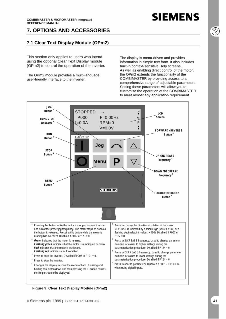
COMBIMASTER & MICROMASTER IntegratedREFERENCE MANUAL
© Siemens plc. 1999 | G85139-H1731-U300-D2 41
7. OPTIONS AND ACCESSORIES
7.1 Clear Text Display Module (OPm2)
This section only applies to users who intendusing the optional Clear Text Display module(OPm2) to control the operation of the inverter.
The OPm2 module provides a multi-languageuser-friendly interface to the inverter.
The display is menu-driven and providesinformation in simple text form. It also includesbuilt-in context-sensitive Help screens.As well as enabling direct control of the motor,the OPm2 extends the functionality of theCOMBIMASTER by providing access to acomprehensive range of adjustable parameters.Setting these parameters will allow you tocustomise the operation of the COMBIMASTERto meet almost any application requirement.
LCDScreen
FORWARD / REVERSEButton 6RUN
Button 3
STOPButton 4
RUN / STOPInducator 2
JOGButton 1
UP / INCREASEFrequency 7
DOWN / DECREASEFrequency 8
Parameterisation
Button 9
1 Pressing this button while the motor is stopped causes it to startand run at the preset jog frequency. The motor stops as soon asthe button is released. Pressing this button while the motor isrunning has no effect. Disabled if P007 or 123 = 0.
2 Green indicates that the motor is running.Flashing green indicates that the motor is ramping up or down.Red indicates that the motor is stationary.Flashing red indicates a fault condition.
3 Press to start the inverter. Disabled if P007 or P121 = 0.4 Press to stop the inverter.5 Changes the display to show the menu options. Pressing and
holding this button down and then pressing the ∇ button causesthe Help screen to be displayed.
6 Press to change the direction of rotation of the motor.REVERSE is indicated by a minus sign (values <100) or aflashing decimal point (values > 100). Disabled if P007 orP122 = 0.
7 Press to INCREASE frequency. Used to change parameternumbers or values to higher settings during theparameterisation procedure. Disabled if P124 = 0.
8 Press to DECREASE frequency. Used to change parameternumbers or values to lower settings during theparameterisation procedure. Disabled if P124 = 0.
9 Press to access parameters. Disabled if P051 - P053 = 14when using digital inputs.
P
Jog
Menu
RUN STOP
MENUButton 5
STOPPED → P000 F=0.00HzI=0.0A RPM=0 V=0.0V
M
M
P
Figure 9 Clear Text Display Module (OPm2)

COMBIMASTER & MICROMASTER IntegratedREFERENCE MANUAL
© Siemens plc. 1999 | G85139-H1731-U300-D242
The user is offered a text-driven format forcommissioning, parameterising, configuring andoperating the inverter. The following features areincluded:
• Illuminated high resolution LCD screenwith adjustable contrast.
• 7 languages.
• Central device for up to 31 inverters whichare networked together via USS.
• Up to 10 parameter sets can be stored innon-volatile memory for uploading anddownloading between the clear textoperator panel and the drive.
• Help texts for diagnosing faults.
• Isolated RS232 interface for connecting toa PC.
Dimensions H x W x D 130 mm x 73 mm x 40 mm
Current drain at 5 V 250 mA
Degree of protection IP 54
Maximum cable length 5m
Table 1: Technical Data
LCDDisplay
FORWARD / REVERSEButton 6
RUNButton 3
STOPButton 4
RUN / STOPInducator 2
JOGButton 1
UP / INCREASEFrequency 7
DOWN / DECREASEFrequency 8
ParameterisationButton 9
P
Jog
Menu
RUN STOP
MENUButton 5
P000 RUNNING →RPM=1250F=50.00HzI=1.5A M=125% P
Indications as to which keys to use are shown inthe right hand column of the screen.
All the main functions are accessible from themain menu screen:
OPERATE UPREAD MDIAG. DOWNLOAD PARAMS LANGUAGE PMODE CONFIG.
Operating display
Diagnosis ofdrive faults
Parameterisedrive
Mode selection for module:Local, Master, Internal, RS232-RS485 convert
Upread parameter setsfrom drive to module
Download parameter setsfrom module to drive
Language selection
Configure module features:Backlight, Contrast, LargeNumbers, Cursor, Help, Reset
Main Menu Screen
Pressing the Menu and " keys simultaneouslycauses a help screen, displaying the key featuresof the Clear Text display module, to appear.
On power-up, unless configured otherwise, thepanel will show the Operating Display.
STOPPED M P000 S=50.00Hz I=0.0A RPM=0 P
V=0.0V
Drive status:Stopped, Running,Fault, Warning
Direction of motor rotation
Output frequency(alternating with setpointwhen drive stopped)
Actual motor speed
Motor voltageMotorcurrent
Operating Display when in Local mode.
M BRUNNING PF=50.00Hz
Drive status:Stopped, Running,Fault, Warning
Output frequency(alternating with setpointwhen drive stopped)
Direction of motor rotation
Drives present on the USS Busin this case 0, 7 and 16, selectablewith arrow keys
Enable broadcast functionto start and stop all driveson bus
Operating Display when in Master mode.
The status LED indicates whether the drive isrunning. When the LED is green, the drive isrunning and when it is red the drive is stopped.When accessing drive parameters, help texts areassociated with the parameter and the parametervalues.
Shows that internallystored parameter setis being accessed
Text describingselected parameter
I PARAMS All M P051=1 M SELECT DIG I/P 1 P run right h
Parameternumber
Indicates that higher and lowerparameter values are available
Text describingselected value
Parameteraccess
Parameter group:All, General, Motor Plate,Ramping, PID, Setpoint, Freq.I/O, Comms. User Interface,Setup, Changed from default

COMBIMASTER & MICROMASTER IntegratedREFERENCE MANUAL
©Siemens plc. 1999 | G85139-H1731-U300-D2 43
RS232 Interface
The Clear text Display is fitted with an RS232interface to allow the drive to be connected to aPC.
1 2 3 4 5
+6V
0V
Figure 10: Pin Layout of the RS232 EdgeConnector
Terminal Function, information
1 NC (not connected)
2 External TxD
3 External RxD
4 External RTS
5 Isolated 0V
Table 2: Terminal functions of the RS232connector
Table 3 gives the ordering information for theOPM2 Clear Text Display Module.
The RS232 interface requires an external powersupply to operate. The specification of the powersupply interface is as follows:
• Voltage tolerance 6V ! 0.5V
• Max Supply Current when connected todrive 50mA, when not connected to drive250mA
• Connecting Plug
• - Outside diameter 3.5mm
• - Inside diameter 1.35mm
Designation Order No.
OPM2 Clear TextDisplay Module
6SE 3290-0XX87-8BF0
Connecting cable OPM3m
6SE 9996-0XA31
Table 3: Ordering Information
7.2 PROFIBUS CB155
This option allows the COMBIMASTER to becontrolled via a PROFIBUS-DP serial bus(SINEC L2-DP).
PROFIBUS-DP is a cost-effective high speedserial communication system optimised for theactuator/sensor area where very short systemreaction times are critical. It operates as adecentralised I/O system whereby thetraditional wiring to the sensors and actuatorsis replaced by an RS485 serial bus systemlinking the stations together.
The suitability of the system for suchapplications has been recently enhanced bythe extension of the bus speed up to 12MBd.The protocol is defined as DIN19245 and alsoas EN50170 guaranteeing open, multi-vendorcommunications between PROFIBUS-DPstations.
Up to 125 stations can be networked togetherusing this single bus system and a very flexibledata structure allows the system to beoptimised to exactly match the requirements ofeach device.
PROFIBUS-DP lies at the heart of the newgeneration of SIMATIC S7 automation systemsoffered by Siemens. Using this single bussystem, all engineering, visualisation and PLCcontrol operations can be integrated. Toconfigure a SIMATIC based automationsystem, all that is required is the associatedSTEP7 configuration tool running on a PC. Busconfiguration is performed by using a drag anddrop technique in a graphically displayedPROFIBUS-DP network.

COMBIMASTER & MICROMASTER IntegratedREFERENCE MANUAL
© Siemens plc. 1999 | G85139-H1731-U300-D244
Below are listed some of the advantages ofautomating a system with PROFIBUS-DP:
• Only one single network for operatorpanels, drives, sensors, actuators,PLCs.
• Cost savings in installation time andcabling.
• Ease of commissioning with theSIMATIC S7 PLC system and STEP7software.
Flexibility to expand or modify the automationsystem at a later date.Simple integration into higher level processvisualisation systems such as PCS7.Remote diagnostics reduce the down-time inthe event of a problem.
Features of CB 155 PROFIBUS Option:
• Permits fast cyclic communications viaa PROFIBUS connection.
• Supports all PROFIBUS baud rates upto 12MBd.
• Control of up to 125 inverters usingPROFIBUS-DP protocol (withrepeaters).
• Conforms with the relevant parts of DIN19245 and EN50170 guaranteeing opencommunications on a serial bus system.It can be used with other PROFIBUS-DP/SINEC L2-DP peripheral devices onthe serial bus. Data format conforms tothe VDI/VDE directive 3689 “PROFIBUSProfile for Variable Speed Drives”.
• Can be easily configured usingSiemens COM ET 200, COM ETWindows or S7 Manager software.
• Simple integration into a SIMATIC S5or S7 PLC system using speciallydesigned functional blocks (S5) andsoftware modules (S7).
• Simply fits to the side of theCOMBIMASTER inverter using twoscrews.
• No separate power supply necessary.
• Digital and analogue inputs can be readand the digital output controlled via theserial bus.
• Approx. 5 ms response time to processdata.
• Output frequency (and therefore motorspeed) can be controlled locally on thedrive or over the serial bus.
• Multi-mode operation possible, wherebycontrol data can be input via the terminalblock (digital inputs) and set point overthe serial bus. Alternatively, the set pointcan be from a local source (analogueinput) with the drive control over theserial bus.
• All drive parameters are accessibleover the serial link.
The PROFIBUS module fits to the side of theCOMBIMASTER using two screws.
COMBIMASTER PROFIBUS Accessories
• The following PROFIBUS accessoriesare available for COMBIMASTER. Allare rated IP65 minimum.
• CM PROFIBUS T Connector - This fitsto the PROFIBUS module, and allowsin/out PROFIBUS cables to beconnected. It also contains thenecessary terminating network for 12Mbaud operation. It is fitted with twofemale circular connectors, and thecable to the CB155
• CM PROFIBUS Terminator - Thishouses the resistive terminating devicesrequired at each end of a PROFIBUSlink. It can be fitted to the lastCOMBIMASTER T piece in the link.
• CM PROFIBUS Cable 1m - 1 metrePROFIBUS cable fitted with two malecircular connectors.
• CM PROFIBUS Cable 5m - 5 metrePROFIBUS cable fitted with two malecircular connectors.
• CM PROFIBUS Cable 10m - 10 metrePROFIBUS cable fitted with two malecircular connectors.
• CM PROFIBUS cable link (10cm) -10cm of PROFIBUS cable fitted with 2female circular connectors, forconnecting two lengths of cable.

COMBIMASTER & MICROMASTER IntegratedREFERENCE MANUAL
©Siemens plc. 1999 | G85139-H1731-U300-D2 45
COMBIMASTER
CB155
T CONNECTOR
COMBIMASTER
CB155
T CONNECTOR
COMBIMASTER
CB155
T CONNECTOR
TERMINATOR
BUS MASTER
INTERCONNECTING CABLES - One ormore cables joined by cable links.
Cable A
Cable B
Cable C
SK200 SK200 SK200
Figure 11 Typical PROFIBUS Installation, Showing Use Of Accessories
PROFIBUS Component Order Number Drawing Reference
CM PROFIBUS module CB155
Note: For CS B Issue A units :-
6SE9996-0XA18
6SE9996-0XA20
Includes Cable A
CM PROFIBUS T connector 6SE9996-0XA21 Includes Cable B
CM PROFIBUS terminator 6SE9996-0XA22
CM PROFIBUS cable 1m 6SE9996-0XA23 Cable C
CM PROFIBUS cable 5m 6SE9996-0XA24 Cable C
CM PROFIBUS cable 10m 6SE9996-0XA25 Cable C
CM PROFIBUS cable link 6SE9996-0XA26 Used for joining lengths of cable C
1. A clear text operator panel(OPM2) is required to set theCOMBIMASTER parametersprior to connecting thePROFIBUS module.
2. The PROFIBUS Module may onlybe connected or disconnectedfrom the drive when the drive ispowered off.
3. The PROFIBUS module must onlybe connected to the drive with thecable supplied for the purpose.
4. The PROFIBUS module cannot beused simultaneously with theClear Text Display module.
The data structure for communication overPROFIBUS-DP can be either PPO type 1 orPPO type 3 as specified in VDI/VDE 3689.This means in practice that process data(control words, set-point in the transmittedtelegram and status words, actual values in thereceived telegram) is always sent.
Parameter data exchange may, however, beblocked if bus or PLC memory space is at apremium. The data structure and thus thePPO type is normally specified by the busmaster. If no PPO type is specified (e.g. if acombined DP/FMS bus master is used), thenthe default PPO type is type 1 (parameter dataenabled). Parameter write access over theserial link can be enabled or blocked asrequired.
For more detailed Information ,refer to Profibus Manual

COMBIMASTER & MICROMASTER IntegratedREFERENCE MANUAL
© Siemens plc. 1999 | G85139-H1731-U300-D246
Parameter read access is permanentlyenabled, allowing continuous read out of drivedata, diagnostics, fault messages etc. Avisualisation system can thus be realised withminimal effort.
The PROFIBUS cable is connected to the 5-way miniature circular socket on the side of thePROFIBUS Module, via a special ‘T’ connectorwhich fits to the edge of the module. This Tconnector allows the PROFIBUS module to bedisconnected from the bus in the event of afault, without breaking the PROFIBUS link.The pin designation of the circular connectorsis given below.
1
2
3
4
51
2
3
4
5
Socket (Pins) Plug (Holes)
Figure 12 Pin Arrangement For The 5-WayCircular PROFIBUS Connector
Note that the socket is used on the PROFIBUSmodule, and the cable links. The plug is usedon the interconnecting cables.
Terminal Function, information
1 +5V
2 N (-)
3 0V
4 P (+)
5 No connection
Table 4: Pin Assignment for the 5-wayCircular PROFIBUS Connector
Data transfer rate(Kbit/s)
Max. cable lengthof a segment (m)
9.619.2
93.75187.5
5001500
12000
1200120012001000 400 200 100
Table 5: Cable Lengths
A segment can be extended by using RS485 repeaters.
Recommendation: RS 485 repeater(Order No.: 6ES7 972-0AA00-0XA0).
For reliable operation of the serial bus system,the cable must be terminated at both endsusing terminating resistors. For operation at12MBd, cables must be terminated inconnectors with a built-in damping network(built into T Connector). Additionally, for12MBd operation, no stub length from the mainbus cable is allowed.Suitable SINEC-L2 DP connectors and cablefor reliable operation up to 12MBd are detailedabove.A floppy disk is supplied with the PROFIBUSmodule containing the handbook and two datafiles for configuring the relevant PLC system.
Quick Guide to Setting Up PROFIBUSCommunications
• The bus cable between the master deviceand the drive must be connected correctly.This includes the necessary terminationresistors and (for 12MBd) the terminatingnetwork.
• The bus cable must be screened and thescreen must be connected to the housing ofthe cable connector.
• The PROFIBUS master must be configuredcorrectly so that communications can berealized with a DP slave using PPO type 1or PPO type 3 (only PPO type 1, if the PPOtype cannot be configured via remoteoperator control).
• When using COM ET software with aSIMATIC S5, the correct type descriptionfile must be used, so that an IM 308B/C canbe configured as bus master. When usingthe Simatic Manager for an S7, the ObjectManager must be loaded.
• The bus must be operational (for aSIMATIC module, the operator controlpanel switch must be set to RUN).
• The bus baud rate must not exceed 12MBd.
• The PROFIBUS Module must be correctlyfitted to the inverter and the inverter mustbe powered up.
• The slave address for the drive (parameterP918) must be set so that it corresponds tothe slave address configured at thePROFIBUS master, and must be uniquelydefined on the bus.

COMBIMASTER & MICROMASTER IntegratedREFERENCE MANUAL
©Siemens plc. 1999 | G85139-H1731-U300-D2 47
Installation should be in conformance withEMC directives and regulations (this isdescribed in section 4 and in the operatingmanuals for the PLC).
DimensionsH x W x D
115 mm x 90 mm x30 mm
Degree of protection IP 65
Maximum busspeed
12MBd
Table 6: Technical Data
7.3 Control and Commissioning withSIMOVIS
The SIMOVIS drive commissioning softwareoperates under Windows 95 or NT and can beused to configure the COMBIMASTER,MICROMASTER, MICROMASTER Vector andMIDIMASTER Vector drives.
SIMOVIS offers the following benefits:• Access from the same PC to one or
several drives connected to the sameserial bus.
• Storage of parameter sets on the PC.
• Control and monitoring of the drives.
• Simplified, text driven, access to allparameters within the drive.
• Upread and download of entireparameter sets.
• Off-line configuration for alteringparameter sets stored on the PC harddisk drive without a connection to thedrive.
• Interface to the S7 Manager to allowconfiguring of drives on a PROFIBUSDP* link within an automation system.
* Requires a communication board tooperate via PROFIBUS –Ref No.6GK1541-1AA00 PROFIBUS CP5411.
The minimum recommended PCspecification for operation ofSIMOVIS is a 90MHz Pentiumwith 32MB of RAM, 200MB harddrive and WINDOWS95 or NT4.0
Designation Order No.
SIMOVIS StandaloneVersion
6SE3290-0XX87-8SA2
Block package forSIMATIC S7 includingDVA_S7 and ObjectManager
6SX7005-0CB00
Table 7: SIMOVIS Ordering Information
Standalone Operation of SIMOVIS
For direct configuration of one or more drives,SIMOVIS communicates over the PC serialport, COM1 or COM2. An RS232/485converter must be connected between the PCand the drive. The Clear Text Display moduleis suitable for this purpose – refer to section7.1.
Following installation, the Buskon programmust be called to define whether one or moredrives is connected to the PC. For eachconnected drive, the drive type must beselected from the hardware directory and thebus address must match the valueprogrammed into P091 in the drive.
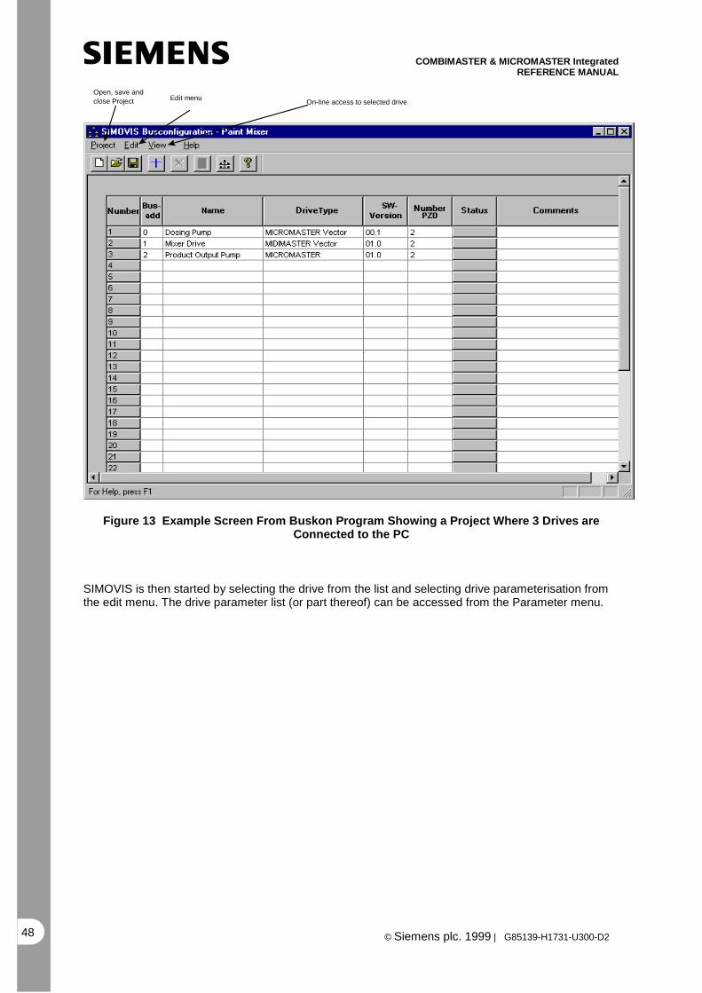
COMBIMASTER & MICROMASTER IntegratedREFERENCE MANUAL
© Siemens plc. 1999 | G85139-H1731-U300-D248
Open, save andclose Project On-line access to selected drive
Edit menu
Figure 13 Example Screen From Buskon Program Showing a Project Where 3 Drives areConnected to the PC
SIMOVIS is then started by selecting the drive from the list and selecting drive parameterisation fromthe edit menu. The drive parameter list (or part thereof) can be accessed from the Parameter menu.

COMBIMASTER & MICROMASTER IntegratedREFERENCE MANUAL
©Siemens plc. 1999 | G85139-H1731-U300-D2 49
On/Off Control for Drive Drives found on Bus
Drive data (parametersets) save, open,upload, download
Parameter set inRAM, EEPROMor PC drive
Parameter screen view,full list or specificparameter groups
Direct Accessto drive processdata
Figure 14 Example Screen From SIMOVIS Where Access to the Whole Parameter List Has BeenSelected
Operation of SIMOVIS within an Automation System
SIMOVIS can access the drives on aPROFIBUS DP system when run on a PC orPG with Step 7 V3.2 or higher. In this case theBuskon program is not used and SIMOVIS canbe called directly by selecting the requireddrive from the Step7 HWConfig program oncethe PROFIBUS network has been configured.
Access to the drive parameters is identical tothe standalone case. Details on how toconfigure the automation system are to befound in the relevant Step7 documentation.The hardware requirement for SIMOVIS isidentical to that for Step 7.

COMBIMASTER & MICROMASTER IntegratedREFERENCE MANUAL
© Siemens plc. 1999 | G85139-H1731-U300-D250
7.4 Brake Options
Pulse Resistor Braking Unit(Only available for CS B Inverters)
The pulse resistor braking unit gives theCOMBIMASTER increased immunity to overvoltage trips, and can also be used to provideup to 7kW (peak) of braking power for stoppingthe system more quickly than would otherwisebe possible.
The braking unit fits in place of the standardcover for the inverter unit. It houses the brakingcontrol electronics, and a 7kW (peak) brakingresistor with heat sink. Full IP65 environmentalprotection is maintained.
Technical Overview
The electronics operates completelyindependently of the inverter electronics,monitoring the DC link voltage. During braking,the motor will regenerate, causing the DC linkvoltage to rise. When a set threshold isreached, the unit switches the resistor onto theDC link, causing the regenerated energy to bedissipated as heat in the resistor, andpreventing an over voltage trip.
While the resistor is switched on, itstemperature will rise. When a thresholdtemperature (Tmax) is reached, the unit willlimit the power in the resistor to approximately5% of the peak power. (350W). If thetemperature continues to rise, the resistor willbe disabled completely, until the temperaturehas reduced. The following diagrams show therelationship between braking power, andresistor temperature with time.
P1
P2
T2T1
T2T1
Tmax
Figures given below are for a 7kW (peak)braking unit. T1 and T2 are variable,depending on ambient temperature. Howevertypical figures are given.
P1 - 7kWP2 - 350WT1 - 5 Seconds typicalT2 - 100 Seconds typical
Protection
In the event of a braking unit fault, it is possiblefor the resistor to become permanentlyconnected, and to overheat. The resistortemperature is monitored by an internal circuit,and if it becomes too hot , this is indicated by afault relay. This relay should be used to controlan external contactor, to remove power fromthe COMBIMASTER. See the braking unitinstallation instructions for more information.

COMBIMASTER & MICROMASTER IntegratedREFERENCE MANUAL
© Siemens plc. 1999 | G85139-H1731-U300-D2 51
Electromechanical Brake Control
The electromechanical brake control, allowsthe COMBIMASTER to directly control anelectromechanical brake.The brake control fits in place of the standardcover for the inverter unit. Full IP65environmental protection is maintained.The unit provides an output to drive the coil ofa DC electromechanical brake. It can beconfigured for both fast, and slow operation ofthe coil. The unit is set up using theparameters P062, P063 and P064, whichallows full control of the brake release time,and brake stopping time.
Brake coil voltage output will be 180VDC for400V mains input, and 205VDC for 230Vmains input.
Note that the coil voltage for 400V units of180VDC is not suitable for the standardSiemens electromechanical brake option G26.(refer to Siemens Catalogue M11)
For other mains voltages, the coil voltage willbe:
0.9*Vmains for Vmains = 208V to 240V0.45*Vmains for Vmains = 380V to 500V.
Designation Order No.
Pulse Resistor BrakingUnit (including E-Mbrake control)
-CS B only
6SE9996 –0XA11
ElectromechanicalBrake Control Unit
-CS B
6SE9996 –0XA10
ElectromechanicalBrake Control Unit
-CS A*
6SE9996 –0XA07
Table 8: Brake Options OrderingInformation
* Product release date expected August 1999,please contact your local Siemens sales officefor further information.
7.5 Fan Assembly Options
Fan Assemblies are only required for theMICROMASTER Integrated Inverters.
A fan assembly unit is only required when themotor associated with the MMI unit does notinclude a special cutout in the Motor Fan Cowl(with the inverter heatsink positioned justabove this cutout).
The following fan options can be ordered usingeither the Order Reference Number or addedto the MICROMASTER Integrated OrderNumber using the option short code.
The fan assemblies can be customer fitted ifrequired.
Designation Order No.
Fan assembly
-for CS B
6SE9996 –0XA02
(Short Code - forordering: M41)
Fan assembly
-for CS A
6SE9996 –0XA01
(Short Code - forordering: M41)

COMBIMASTER & MICROMASTER IntegratedREFERENCE MANUAL
© Siemens plc. 1999 | G85139-H1731-U300-D252
7.6 Motor Interface Plate Options
The Motor Interface Plate (MIP) arrangements differ between motor types and inverter case sizes. Fora full description of the MIP options, please refer to section 9.2 of this document.
Ordering Information - Motor Interface Plates
Inverter Case Size Motor type MIP Type Motor Order NumberFrame Size
CS A 1LA7(Siemens) Specific 56 to 71 6SE9996-0XA51
CS A 1LA7 Specific 80 to 90 6SE9996-0XA52
CS B 1LA5 Specific 90 to 132 6SE9996-0XA40
CS B 1LA7 Specific 90 *
CS B 1LA7 Specific 100 to 112 6SE9996-0XA41
CS B 1LA7 Specific 132 6SE9996-0XA42
CS A Any ‘Universal’ ** 6SE9996-0XA44
CS B Any ‘Universal’ ** *
* Not available at time of writing.
**The above Universal MIPs will usually need additional simple ‘base plates’ to customise for aspecific motor - refer to the Section 9.2 for description.

COMBIMASTER & MICROMASTER IntegratedREFERENCE MANUAL
© Siemens plc. 1999 | G85139-H1731-U300-D2 53
8. SPECIFICATIONS
8.1 Mechanical Data – Dimensional Drawings
COMBIMASTER - Case Size A
CGUW
TH
UL
SF
TL
SG
3SLS
PSG
2SG
1
MG
DIM
EN
SIO
N min
10 10 10 10 10180 187 178 239 268157 164 155 216 245134 141 132 193 222108 115 106 167 19676 83 74 135 164199 206 224 247 265160 160 160 160 16048 55 46 107 136205 244 269 303 361122 122 122 122 122 66 66 66 66 66230 237 255 278 296
LCSG3SLSPSG2SG1MGULSFTLUWCGTH
56 63 71 80 90MOTOR FRAME SIZE
Dimensions in mm
For detailed Motor Dimension drawings, please refer to Siemens Catalogue M11 (ref.: E20002-K1711-A101-A3-7600), Section 8 Dimension Drawings.

COMBIMASTER & MICROMASTER IntegratedREFERENCE MANUAL
© Siemens plc. 1999 | G85139-H1731-U300-D254
COMBIMASTER - Case Size B
MG2
CG
UW
TH
UL
SF
TL
LC
SG
3SLSPS
G2SG
1
MG2
MG1
213 262 262 298 10 10 10 10
MOTOR FRAME SIZE
361 424 445 506
THCG
TLUW
min
UL
SG1
MG1
SF
DIM
EN
SIO
N
SLSP
LCSG3
SG2
90 100 112 132 317 333 357 396
171 171 171 171
243 243 243 243 249 265 289 323
120 169 169 205156 205 205 241181 230 230 266193 242 242 278
90 139 139 175
86 86 86 86
269 285 309 348
Dimensions in mm.
For detailed Motor Dimension drawings, please refer to Siemens Catalogue M11 (ref.: E20002-K1711-A101-A3-7600), Section 8 Dimension Drawings.

COMBIMASTER & MICROMASTER IntegratedREFERENCE MANUAL
© Siemens plc. 1999 | G85139-H1731-U300-D2 55
COMBIMASTER - Case Size A - Deep CoverDeep Cover – used for Electromechanical Brake Control Unit & Class B Filter (400V only)
(for Dimension TH for Case Size A , please refer to table on Page 53)
TH
+22
COMBIMASTER - Case Size B – Deep Covers
Deeper Covers:i) Resistor Brake (incl. Heatsink)ii) Mechanical Brake
(for Dimension TH for Case Size B , please refer to table on Page 54)
For detailed Motor Dimension drawings, please refer to Siemens Catalogue M11 (ref.: E20002-K1711-A101-A3-7600), Section 8 Dimension Drawings.
TH
+30
TH
+77
Dimensions in mm.For detailed Motor Dimension drawings, please refer to Siemens Catalogue M11 (ref.: E20002-K1711-A101-A3-7600), Section 8 Dimension Drawings.

COMBIMASTER & MICROMASTER IntegratedREFERENCE MANUAL
© Siemens plc. 1999 | G85139-H1731-U300-D256
MICROMASTER Integrated - Case Size A
122
66
133
28
60
111
66
122
10
80
160
13210
9
86
Note : Deep Cover (used for Electromechanical With Normal Cover Brake Control unit
& Class B Filter – 400V only)
Dimensions in mm.

COMBIMASTER & MICROMASTER IntegratedREFERENCE MANUAL
© Siemens plc. 1999 | G85139-H1731-U300-D2 57
MICROMASTER Integrated - Case Size B
86
171
211
86
171
164
123
10.0
10391
66
30
83
63
134
86
171
243
With Pulse Resistor With Electromechanical With Normal CoverBrake Unit Cover Brake Unit Cover
(also used for :4kw,5.5kW & 7.5kWclass B filter units)
Dimensions in mm.

COMBIMASTER & MICROMASTER IntegratedREFERENCE MANUAL
© Siemens plc. 1999 | G85139-H1731-U300-D258
COMBIMASTER Option – Profibus Module CB155
171
126
190
150
90
30
120
107
Dimensions in mm

COMBIMASTER & MICROMASTER IntegratedREFERENCE MANUAL
© Siemens plc. 1999 | G85139-H1731-U300-D2 59
8.2 Electrical Data
GeneralFeature Specification
COMBIMASTER MICROMASTER Integrated208-240V ± 10% 1/3 Phase380-500V ± 10% 3 Phase *
208-240V±10% 1/3 Ph.380-500V±10% 3 Ph. *
Mains voltageTorque derating required for < 380Vrms
* In case of unearthed mains please contact Siemens
Power Ranges 1AC 208-240V3AC 208-240V3AC 380-500V
0.12kW – 0.75kW0.12kW – 0.75kW0.37kW – 7.5kW
Control Method V/fInput frequency: 47 Hz to 63 HzOutput frequency : CM : 0 Hz to 140 Hz (motor
dependent)MMI: 0 Hz to 400 Hz
Setpoint resolution: 0.05 HzOverload capability: 150% for 60 s, related to nominal currentProtection against: Inverter overtemperature, Motor overtemperature
Overvoltage , UndervoltageLocked Rotor, Motor pull-out
Standard Functions DC Injection braking, also when motor stationary4 quadrant operation
Programmable auto-restart following mains break or faultFlying start for already spinning motor
2 programmable ramp generators (0-650s) each with S-curvecapability
Local Setpoint Built – in potentiometerDigital Inputs 3Analogue Input: 0/2 - 10 V
0 - 20 mA/4 - 20 mAPI Input: 0 - 10 V
0 - 20 mAAnalogue setpoint resolution: 10-bitSetpoint stability: Analogue < 1%
Digital < 0.02%Motor temperature monitoring: l2t control
PTC inputRamp times: 0 - 650 s
1 relay 30 V DC / 1 AControl outputs:
WARNING
External inductive loads must be suppressed in an appropriatemanner (see Section 4.1 Electrical Installation – GeneralWiring Guidelines – Paragraph. 4).
Serial Interface: RS485Inverter efficiency: 97% typicalOperating temperature: -10oC to +40oC -10oC to +50oCStorage/transport temperature: -40oC to +70oCHumidity: 99% non-condensingInstallation height above sea level: < 1000 mDegree of protection: IP55 IP65Protective separation of circuits: Double insulation or protective screeningElectro-magnetic compatibility (EMC): Optional EMC Filters to EN55011 Class A or B
See section 9.3 - EMCWeights CS A: ca 3.5 Kg (depending on options selected)
CS B: ca 5.6 Kg (depending on options selected)

COMBIMASTER & MICROMASTER IntegratedREFERENCE MANUAL
© Siemens plc. 1999 | G85139-H1731-U300-D260
8.3 De-rating Information
De-rating with altitude
500 1000 2000 3000 4000
100
90
80
70
60
Maximum rated input voltage%
Installation Altitudein m above sea level
500 1000 2000 3000 4000
100
90
80
70
60
Maximum rated continuoustorque. (M/Mn) %.
Installation Altitudein m above sea level
De-rating with switching frequency De-rating with mains input voltage
100
90
80
70
60Pulse FrequencykHz
4 8 16
230V Input units400V Input units
Maximum rated continuoustorque. (M/Mn) %.
345 350 360 370 380 390 400 400V Units195 200 210 220 230 240 230V Units
100
90
80
70
60
Mains input voltageV
Maximum rated continuoustorque. (M/Mn) %
De-rating with temperature De-rating with inverter frequency
35 40 50 60 70
100
80
60
40
20
Ambient Temperature
Maximum rated continuoustorque. (M/Mn) %
CM
MMI
5 10 20 30 40 50 60
100
90
80
70
60
Inverter FrequencyHz
Maximum rated continuoustorque. (M/Mn) %
Temperature Class F
Force Cooled Motors

COMBIMASTER & MICROMASTER IntegratedREFERENCE MANUAL
© Siemens plc. 1999 | G85139-H1731-U300-D2 61
8.4 Technical Data - COMBIMASTER
CS A Low Voltage Single Phase Units
Model: CM12 CM25 CM37 CM55 CM75Order Number: *
2 pole
4 pole
1UA7053-2B[z]0.
1UA7060-4B[z]0.
1UA7063-2B[z]0.
1UA7070-4B[z]0.
1UA7070-2B[z]0.
1UA7073-4B[z]0.
1UA7073-2B[z]0.
1UA7080-4B[z]0.
1UA7080-2B[z]0.
1UA7083-4B[z]0.
Frame size:
2 pole
4 pole
56
63
63
71
71
71
71
80
80
80
Motor OutputRating:
0.12kW
0.16hp
0.25kW
0.33hp
0.37kW
0.49hp
0.55kW
0.73hp
0.75kw
1.0hp
Operating InputVoltage: 1∅ AC 208 – 240 Vrms ± 10%
Operating InputFrequency: 47 – 63 Hz
OutputFrequency: 0 – 50Hz
Output Frequencywith Opm2 orserial link:
2 pole
4 pole0 – 100Hz
0 – 140Hz
0 – 100Hz
0 – 140Hz
0 – 100Hz
0 – 140Hz
0 – 100Hz
0 – 140Hz
0 – 100Hz
0 – 140Hz
Input Current: 1.8 A rms 3.2 A rms 4.6 A rms 6.2 A rms 8.2 A rms
Mains fuse: 10 A 16 A
Mains Lead cross-section 1mm2 1.5mm2
* [z] = filter option: U = Unfiltered, A = Class A filter, B = Class B filter.
Position 12 (shown as “.”) is for the construction type from the Siemens catalogue, M11 (Ref. No.E2002-K1711-A201-A2-7600).
CS A Low Voltage Three Phase Units
Model: CM12/2 CM25/2 CM37/2 CM55/2 CM75/2Order Number: *
2 pole
4 pole
1UA7053-2BU1.
1UA7060-4BU1.
1UA7063-2BU1.
1UA7070-4BU1.
1UA7070-2BU1.
1UA7073-4BU1.
1UA7073-2BU1.
1UA7080-4BU1.
1UA7080-2BU1.
1UA7083-4BU1.
Frame size:
2 pole
4 pole
56
63
63
71
71
71
71
80
80
80
Motor OutputRating:
0.12kW
0.16hp
0.25kW
0.33hp
0.37kW
0.49hp
0.55kW
0.73hp
0.75kw
1.0hp
Operating InputVoltage: 3∅ AC 208 – 240 Vrms ± 10%
Operating InputFrequency: 47 – 63 Hz
Output Frequency: 0 – 50Hz
Output Frequencywith Opm2 orserial link:
2 pole
4 pole0 – 100Hz
0 – 140Hz
0 – 100Hz
0 – 140Hz
0 – 100Hz
0 – 140Hz
0 – 100Hz
0 – 140Hz
0 – 100Hz
0 – 140Hz
Input Current: 1.1 A rms 1.9 A rms 2.7 A rms 3.6 A rms 4.7 A rms
Mains fuse: 10 A
Mains Lead cross-section 1mm2
* Note that these units are available Unfiltered only.
Position 12 (shown as “.”) is for the construction type from the Siemens catalogue, M11 (Ref. No.E2002-K1711-A201-A2-7600).
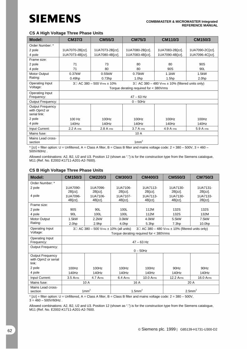
COMBIMASTER & MICROMASTER IntegratedREFERENCE MANUAL
© Siemens plc. 1999 | G85139-H1731-U300-D262
CS A High Voltage Three Phase Units
Model: CM37/3 CM55/3 CM75/3 CM110/3 CM150/3Order Number: *
2 pole
4 pole
1UA7070-2B[zz].
1UA7073-4B[zz].
1UA7073-2B[zz].
1UA7080-4B[zz].
1UA7080-2B[zz].
1UA7083-4B[zz].
1UA7083-2B[zz].
1UA7090-4B[zz].
1UA7090-2C[zz].
1UA7096-4C[zz].
Frame size:
2 pole
4 pole
71
71
73
80
80
80
80
90S
90S
90L
Motor OutputRating:
0.37kW
0.49hp
0.55kW
0.73hp
0.75kW
1.0hp
1.1kW
1.5hp
1.5kW
2.0hp
Operating InputVoltage:
3∅ AC 380 – 500 Vrms ± 10% 3∅ AC 380 – 480 Vrms ± 10% (filtered units only)
Torque derating required for < 380Vrms
Operating InputFrequency: 47 – 63 Hz
Output Frequency: 0 – 50Hz
Output Frequencywith Opm2 orserial link:
2 pole
4 pole100 Hz
140Hz
100Hz
140Hz
100Hz
140Hz
100Hz
140Hz
100Hz
140Hz
Input Current: 2.2 A rms 2.8 A rms 3.7 A rms 4.9 A rms 5.9 A rms
Mains fuse: 10 A
Mains Lead cross-section 1mm2
* [zz] = filter option: U = Unfiltered, A = Class A filter, B = Class B filter and mains voltage code: 2 = 380 – 500V, 3 = 460 –500V/60Hz .
Allowed combinations: A2, B2, U2 and U3. Position 12 (shown as “.”) is for the construction type from the Siemens catalogue,M11 (Ref. No. E2002-K1711-A201-A2-7600).
CS B High Voltage Three Phase Units
Model: CM150/3 CM220/3 CM300/3 CM400/3 CM550/3 CM750/3Order Number: *
2 pole
4 pole
1UA7090-2B[zz].
1UA7096-4B[zz].
1UA7096-2B[zz].
1UA7106-4B[zz].
1UA7106-2B[zz].
1UA7107-4B[zz].
1UA7113-2B[zz].
1UA7113-4B[zz].
1UA7130-2B[zz].
1UA7130-4B[zz].
1UA7131-2B[zz].
1UA7133-2B[zz].
Frame size:
2 pole
4 pole
90S
90L
90L
100L
100L
100L
112M
112M
132S
132S
132S
132M
Motor OutputRating:
1.5kW
2.0hp
2.2kW
2.9hp
3.0kW
4.0hp
4.0kW
5.3hp
5.5kW
7.3hp
7.5kW
10.0hp
Operating InputVoltage:
3∅ AC 380 – 500 Vrms ± 10% (all units) 3∅ AC 380 – 480 Vrms ± 10% (filtered units only)
Torque derating required for < 380Vrms
Operating InputFrequency: 47 – 63 Hz
Output Frequency:0 – 50Hz
Output Frequencywith Opm2 or seriallink:
2 pole
4 pole100Hz
140Hz
100Hz
140Hz
100Hz
140Hz
100Hz
140Hz
90Hz
140Hz
90Hz
140Hz
Input Current: 3.5 Arms 4.7 Arms 6.4 Arms 10.0 Arms 12.2 Arms 16.0 Arms
Mains fuse: 10 A 16 A 20 A
Mains Lead cross-section 1mm2 1.5mm2 2.5mm2
* [zz] = filter option: U = Unfiltered, A = Class A filter, B = Class B filter and mains voltage code: 2 = 380 – 500V,3 = 460 – 500V/60Hz .
Allowed combinations: A2, B2, U2 and U3. Position 12 (shown as “.”) is for the construction type from the Siemens catalogue,M11 (Ref. No. E2002-K1711-A201-A2-7600.

COMBIMASTER & MICROMASTER IntegratedREFERENCE MANUAL
© Siemens plc. 1999 | G85139-H1731-U300-D2 63
8.5 Technical Data - MICROMASTER Integrated
CS A Low Voltage Single Phase Units
Model: MI12 MI25 MI37 MI55 MI75Order Number: * 6SE9610-
7BF[y]0-Z=C876SE9611-
5BF[y]0-Z=C876SE9612-
0BF[y]0-Z=C876SE9612-
6BF[y]0-Z=C876SE9613-4BF[y]0-
Z=C87
Motor OutputRating:
0.12kW
0.16hp
0.25kW
0.33hp
0.37kW
0.49hp
0.55kW
0.73hp
0.75kw
1.0hp
Operating InputVoltage: 1∅ AC 208 – 240 Vrms ± 10%
Operating InputFrequency: 47 – 63 Hz
Output Frequency: 0 – 50Hz
Output Frequencywith Opm2 or seriallink:
2 pole & 4 pole0 – 400Hz
Input Current: 1.8 A rms 3.2 A rms 4.6 A rms 6.2 A rms 8.2 A rms
Mains Fuse: 10 A 16 A
Mains Lead cross-section 1mm2 1.5mm2
* [y] = filter option: 1 = Unfiltered, 5 = Class A filter, 6 = Class B filter.
CS A Low Voltage Three Phase Units
Model: MI12/2 MI25/2 MI37/2 MI55/2 MI75/2Order Number: * 6SE9610-7CF10-
Z=C876SE9611-5CF10-
Z=C876SE9612-0CF10-
Z=C876SE9612-6CF10-
Z=C876SE9613-4CF10-
Z=C87
Motor OutputRating:
0.12kW
0.16hp
0.25kW
0.33hp
0.37kW
0.49hp
0.55kW
0.73hp
0.75kw
1.0hp
Operating InputVoltage: 3∅ AC 208 – 240 Vrms ± 10%
Operating InputFrequency: 47 – 63 Hz
OutputFrequency: 0 – 50Hz
Output Frequencywith Opm2 orserial link:
2 pole & 4 pole0 – 400Hz
Input Current: 1.1 A rms 1.9 A rms 2.7 A rms 3.6 A rms 4.7 A rms
Mains Fuse: 10 A
Mains Lead cross-section 1mm2
* Note that these units are available Unfiltered only.

COMBIMASTER & MICROMASTER IntegratedREFERENCE MANUAL
© Siemens plc. 1999 | G85139-H1731-U300-D264
CS A High Voltage Three Phase Units
Model: MI37/3 MI55/3 MI75/3 MI110/3 MI150/3Order Number: * 6SE9611-
1DF[y]0-Z=C876SE9611-
4DF[y]0-Z=C876SE9611-
8DF[y]0-Z=C876SE9612-
7DF[y]0-Z=C876SE9613-
7DF[y]0-Z=C87
Motor OutputRating:
0.37kW
0.49hp
0.55kW
0.73hp
0.75kW
1.0hp
1.1kW
1.5hp
1.5kW
2.0hp
Operating InputVoltage: 3∅ AC 380 – 500 Vrms ± 10% (all units) 3∅ AC 380 – 480 Vrms ± 10% (filtered units only)
Operating InputFrequency: 47 – 63 Hz
OutputFrequency: 0 – 50Hz
Output Frequencywith Opm2 orserial link:
2 pole & 4 pole 0-400Hz
Input Current: 2.2 A rms 2.8 A rms 3.7 A rms 4.9 A rms 5.9 A rms
Mains Fuse: 10 A
Mains Lead cross-section 1mm2
* [y] = filter option: 1 = Unfiltered, 5 = Class A filter, 6 = Class B filter
CS B High Voltage Three Phase Units
Model: MI150/3 MI220/3 MI300/3 MI400/3 MI550/3 MI750/3Order Number:*
6SE9613-7DD[y]0-Z=C87
6SE9615-8DD[y]0-Z=C87
6SE9617-3DD[y]0-Z=C87
6SE9621-1DD[y]0-Z=C87
6SE9621-3DD[y]0-Z=C87
6SE9621-7DD[y]0-Z=C87
Motor OutputRating:
1.5kW
2.0hp
2.2kW
2.9hp
3.0kW
4.0hp
4.0kW
5.3hp
5.5kW
7.3hp
7.5kW
10.0hp
OperatingInput Voltage: 3∅ AC 380 – 500 Vrms ± 10% (all units) 3∅ AC 380 – 480 Vrms ± 10% (filtered units only)
OperatingInputFrequency:
47 – 63 Hz
OutputFrequency: 0 – 50Hz
OutputFrequencywith Opm2 orserial link:
2 pole & 4 pole 0-400Hz
Input Current: 3.5 A rms 4.7 A rms 6.4 A rms 10.0 A rms 12.2 A rms 16.0 A rms
Mains Fuse: 10 A 16 A 20 A
Mains Leadcross-section 1mm2 1.5mm2 2.5mm2
*[y] = filter option: 1 = Unfiltered, 5 = Class A filter, 6 = Class B filter.

COMBIMASTER & MICROMASTER IntegratedREFERENCE MANUAL
© Siemens plc. 1999 | G85139-H1731-U300-D2 65
8.6 Output Current Ratings - MICROMASTER Integrated
The MICROMASTER Integrated is designed to be fitted to a motor, and in most cases, to useair from the motor fan for cooling of the inverter. For this reason it is not possible to specifycontinuous current ratings which will be achieved under all circumstances. This sectionprovides information about the designed current ratings, and explains the factors which effectthe continuous ratings achievable when the inverter is installed on a motor.
IntroductionThere are two factors in the design of aninverter which define what current can bedelivered the motor :The first factor is the selection of electroniccomponents. For example, the current rating ofthe transistors in the output stage of theinverter. This factor normally limits the peak(short time) current that the inverter canprovide.
The second factor is the method of cooling ofthe inverter. Whenever current flows through aconductor, or an electronic component, heat isgenerated. The cooling method chosen for theinverter must be able to remove enough heatso that when the inverter is run at its maximumcurrent rating continuously then
none of the components in the inverter exceedtheir rated operating temperatures.With a standard inverter, the cooling method ispart of the design of the inverter, therefore it ispossible to specify the continuous currentratings of the inverter when it is correctlyinstalled.
The cooling efficiency for MICROMASTERIntegrated is dependant upon the motor towhich it is fitted, and therefore the continuouscurrent rating must be determined by thermaltests, when the inverter is fitted to the targetmotor.
Designed Current Ratings.The following table gives the designed currentratings for the MICROMASTER Integrated. Allthe inverters are capable of short-termoverload up to 150% of the values shown.
Power RatingsVoltage Class 208 - 240V 380 - 500V
Type P(kW) P(Hp) I (A) KVA P(kW) P(Hp) I (A) KVAMI12 0.12 0.16 0.8 0.32MI25 0.25 0.33 1.7 0.67MI37 0.37 0.50 2.3 0.91 0.37 0.50 1.1 0.76MI55 0.55 0.75 3.0 1.2 0.55 0.75 1.4 0.97MI75 0.75 1.00 3.9 1.5 0.75 1.00 1.9 1.3MI110 1.10 1.50 2.7 1.9MI150 CS A Inverter 1.50 2.00 3.75 2.6MI150 CS B Inverter 1.50 2.00 4.0 2.8MI220 2.20 3.00 5.9 4.0MI300 3.00 4.00 7.7 5.2MI400 4.00 5.30 10.2 7.0MI550 5.50 7.30 13.2 9.0MI750 7.50 10.0 17.0 12.0

COMBIMASTER & MICROMASTER IntegratedREFERENCE MANUAL
© Siemens plc. 1999 | G85139-H1731-U300-D266
Continuous Current Ratings.As explained above, the continuous ratingdepends on the amount of cooling available forthe inverter from the motor fan. This can beaffected by one or more of the following:
Size of Motor Fan Cover CutoutThere must be a hole cut in the motor fancover to allow air from the motor fan to bedirected onto the inverter heatsink. The sizeand shape of this hole affects the airflow to theinverter.
Position of the InverterIdeally, the inverter should be positioned sothat the hole in the motor fan cover is centereddirectly beneath the inverter heatsink. Inaddition, the vertical distance from the fancover to the inverter heatsink should be assmall as possible.
Motor SpeedWhen the motor fan is driven by the motorshaft, then a slower motor will have less airflow to the inverter.
Mains VoltageWhen the 380 to 500V inverters are operatedon a high mains voltage, there is normallymore heat generated in the inverter. This willresult in a lower continuous current rating. Thisis not normally a problem, because a motoroperated at the higher voltage will require lesscurrent to deliver the same shaft power.

COMBIMASTER & MICROMASTER IntegratedREFERENCE MANUAL
© Siemens plc. 1999 | G85139-H1731-U300-D2 67
9. SUPPLEMENTARY INFORMATION
9.1 Application Example
Set-up Procedure for a Simple Application
Application requirements: Normal operating frequency set within range 15 - 50 Hz via anexternal potentiometer. Counter-clockwise rotation required.
COMBIMASTER used: Any model.
Procedure: 1. Remove the link (if fitted) between control terminals 5 and 8.
2. Connect a simple on/off switch to control terminals 6 and 8 forreverse rotation.
3. Connect a 4.7 kΩ potentiometer to the control terminals (seeFigure 4).
4. Set jumper JP301 (‘V’ - voltage) - see Fig.3(CS A), Fig.2 (CS B).
5. Set the internal and external potentiometers fully counter-clockwise and then apply mains power and switch on.
6. Turn the internal potentiometer clockwise until the motor rotates ata speed that approximates to 15 Hz.
7. The external potentiometer now has a range of between 15 Hz atits lowest setting and 50 Hz at its highest setting.

COMBIMASTER & MICROMASTER IntegratedREFERENCE MANUAL
© Siemens plc. 1999 | G85139-H1731-U300-D268
9.2 Motor Interface Plates
Since approximately 01/99 all 1LA5 motors used with COMBIMASTER & MICROMASTER Integratedhave been replaced with the 1LA7 equivalents. This has resulted in changes to the motor interfaceplates (MIP) used with Siemens Motors.
For each inverter case size there are now 3 basic types of motor interface plate:
1LA51LA7‘Universal’
The 1LA5 and 1LA7 interface plates are for use with the Siemens motors.
The ‘Universal’ plate has been designed to simplify adapting the COMBIMASTER for other motors. Inmost cases, the ‘Universal’ motor interface plate can be used with a simple flat metal ‘Base Plate’ andno tooling is required.
The following pages describe the MIPs.

COMBIMASTER & MICROMASTER IntegratedREFERENCE MANUAL
© Siemens plc. 1999 | G85139-H1731-U300-D2 69
Siemens 1LA5 MotorCase Size A Inverter
Topside
Underside
Description
Availability
Variants
Standard MIP for 1LA5 Motors and CS Ainverters.
Discontinued
1 for all motor frame sizes – 6SE9996-0XA43
Siemens 1LA5 MotorCase Size B Inverter
Topside
Description
Variants
Standard MIP for 1LA5 motors and CS B Inverters
1 For all motor frame sizes – 6SE9996-0XA40

COMBIMASTER & MICROMASTER IntegratedREFERENCE MANUAL
© Siemens plc. 1999 | G85139-H1731-U300-D270
Siemens 1LA7 MotorCase Size A Inverter
Topside
Underside
Variant with base plate (MotorFrame Size 80,90)
Description
Variants
Standard MIP for 1LA7 Motors and CS A inverters.
The variant for Motor frames 80 and 90 uses a baseplate (shown)
Motor Frame 56 to 71 – 6SE9996-0XA51Motor Frame 80 to 90 – 6SE9996-0XA52
Siemens 1LA7 MotorCase Size B Inverter
Topside
Description
Variants
Standard MIP for 1LA7 Motors and CS B inverters.
Motor frame 90 -not available at time of writing
Motor Frame 100 & 112 – 6SE9996-0XA41Motor Frame 132 – 6SE9996-0XA42

COMBIMASTER & MICROMASTER IntegratedREFERENCE MANUAL
© Siemens plc. 1999 | G85139-H1731-U300-D2 71
‘Universal’ MIPCase Size A Inverter
Topside
Description
Variants
‘Universal’ MIP for non-Siemens motors, and CS AInverters. It will normally be used with a simple flatmetal base plate to adapt the MIP to the specificmotor.
MIP Assembly – 6SE9996-0XA44
‘Universal’ MIPCase Size B Inverter
Topside
Description
Availability
Variants
‘Universal’ MIP for non-Siemens motors, and CS BInverters. It will normally be used with a simple flatmetal base plate to adapt the MIP to the specificmotor.
From August 1999
MIP Assembly : 6SE9996-0XA53.
Example base plate
Additional description available – please look atpage 7

COMBIMASTER & MICROMASTER IntegratedREFERENCE MANUAL
© Siemens plc. 1999 | G85139-H1731-U300-D272
MIP PCB AssemblyDescription
Variants
The motor interface plate PCB’s have been madeavailable for customers who have designed their ownMIP. They are supplied in order quantities of 50.
PCB for CS A inverters – 6SE9996-0XA47PCB for CS B inverters – 6SE9996-0XA48
Order numbers are for 50 pieces.

COMBIMASTER & MICROMASTER IntegratedREFERENCE MANUAL
© Siemens plc. 1999 | G85139-H1731-U300-D2 73
9.3 Electro-Magnetic Compatibility (EMC)
All manufacturers / assemblers of electricalapparatus which performs a completeintrinsic function which is placed on themarket as a single unit intended for the enduser must comply with the EMC directiveEEC/89/336 after January 1996. There arethree routes by which themanufacturer/assembler can demonstratecompliance:
1. Self-CertificationThis is a manufacturer's declaration that theEuropean standards applicable to theelectrical environment for which theapparatus is intended have been met. Only
standards which have been officiallypublished in the Official Journal of theEuropean Community can be cited in themanufacturer's declaration.
2. Technical Construction FileA technical construction file can be preparedfor the apparatus describing its EMCcharacteristics. This file must be approved bya ‘Competent Body’ appointed by theappropriate European governmentorganisation. This approach allows the use ofstandards which are still in preparation.
3. EC Type-Examination CertificateThis approach is only applicable to radiocommunication transmitting apparatus.
The MICROMASTER Integrated units do not have an intrinsic function until connected with other components(e.g. a motor). Therefore, the basic units are not allowed to be CE marked for compliance with the EMC directive.However, full details are provided below of the EMC performance characteristics of the products when they areinstalled in accordance with the wiring recommendations in section 4.1 of this document.
Class 2: Filtered Industrial (Class A)
This level of performance will allow the manufacturer/assembler to self-certify their apparatus forcompliance with the EMC directive for the industrial environment as regards the EMC performancecharacteristics of the power drive system. Performance limits are as specified in the GenericIndustrial Emissions and Immunity standards EN 50081-2 and EN 50082-2.
EMC Phenomenon Standard Level
Emissions: (CM)
Radiated Emissions EN 55011 Level A1
Conducted Emissions EN 55011 Level A1
Immunity: (CM & MMI)
Supply Voltage Distortion IEC 1000-2-4 (1993)
Voltage Fluctuations, Dips, Unbalance,Frequency Variations
IEC 1000-2-1
Magnetic Fields EN 61000-4-8 50 Hz, 30 A/m
Electrostatic Discharge EN 61000-4-2 8 kV air discharge
Burst Interference EN 61000-4-4 2 kV power cables, 2 kVcontrol
Radio Frequency ElectromagneticField, amplitude modulated
ENV 50 140 27-1000 MHz, 10 V/m,80% AM, power andsignal lines

COMBIMASTER & MICROMASTER IntegratedREFERENCE MANUAL
© Siemens plc. 1999 | G85139-H1731-U300-D274
Class 3: Filtered - for residential, commercial and light industry (Class B)
This level of performance will allow the manufacturer / assembler to self-certify compliance of theirapparatus with the EMC directive for the residential, commercial and light industrial environment asregards the EMC performance characteristics of the power drive system. Performance limits are asspecified in the generic emission and immunity standards EN 50081-1 and EN 50082-1.
EMC Phenomenon Standard Level
Emissions: (CM)
Radiated Emissions EN 55022 Level B1
Conducted Emissions EN 55022 Level B1
Immunity: (CM & MMI)
Electrostatic Discharge EN 61000-4-2 8 kV air discharge
Burst Interference EN 61000-4-4 1 kV power cables, 0.5kV control
The COMBIMASTER is intended exclusively for professional applications.Therefore, it does not fall within the scope of the harmonics emissions specificationEN 61000-3-2.
9.4 Environmental Aspects
Transport and Storage
Protect the COMBIMASTER/MMI againstphysical shocks and vibration duringtransport and storage. The unit must alsobe protected against water (rainfall) andexcessive temperatures (see section 6).
The packaging is re-usable. Retain thepackaging or return it to the manufacturerfor future use.
Dismantling and Disposal
The component parts can be recycled,disposed of in accordance with localrequirements or returned to themanufacturer.
Documentation
This handbook is printed on chlorine-freepaper which has been produced frommanaged sustainable forests. No solventshave been used in the printing or bindingprocess.

COMBIMASTER & MICROMASTER IntegratedREFERENCE MANUAL
© Siemens plc. 1999 | G85139-H1731-U300-D2 75
9.5 Users Parameter Settings
Parameter Default Your settingP000 -
P001 0
P002 10.00
P003 25.00
P004 0.0
P005 50.00
P006 1
P007 0
P009 0
P011 0
P012 0.00
P013 50.00
P014 0.00
P015 0
P016 0
P017 1
P018 0
P019 2.00
P020 25.00
P021 0.00
P022 50.00
P023 2
P024 0
P027 0.00
P028 0.00
P029 0.00
P031 5.00
P032 5.00
P033 10.00
P034 10.00
P035 0
P041 5.00
P042 10.00
P043 15.00
P044 20.00
P045 0
P046 25.00
P047 30.00
P048 35.00
P050 0
P051 1
P052 2
P053 10
P056 0
P058 0.0
P061 6
P062 0
P063 1.0
P064 1.0
P065 1.0
P071 0
P072 500
P073 0
P074 0
P076 0 or 2
Parameter Default Your settingP077 0
P078 50
P079 0
P081 ###
P082 ###
P083 ###
P084 ###
P085 ###
P086 150
P087 0
P089 ###
P091 0
P092 6
P093 0
P094 50.00
P095 0
P099 0
P101 0
P111 ###
P112 8
P113 -
P121 1
P122 1
P123 1
P124 1
P125 1
P131 -
P132 -
P133 -
P134 -
P135 -
P137 -
P140 -
P141 -
P142 -
P143 -
P151 4
P152 5
P201 0
P202 1.0
P203 0.00
P205 1
P206 0
P207 100
P208 0
P210 -
P211 0.00
P212 100.00
P220 0
P331 2
P332 10
P700 See PROFIBUShandbook
P701 See PROFIBUShandbook

COMBIMASTER & MICROMASTER IntegratedREFERENCE MANUAL
© Siemens plc. 1999 | G85139-H1731-U300-D276
Parameter Default Yoursetting
P702 See PROFIBUShandbook
P723 -
P845 50
P880 See PROFIBUShandbook
P910 0
P918 See PROFIBUS /CANhandbook [0]
P922 -
P923 0
P927 See PROFIBUS /CANhandbook [0]
P928 See PROFIBUS /CANhandbook [0]
P930 -
P931 -
P944 0
P947 See PROFIBUShandbook
P958 See PROFIBUShandbook
Parameter Default Yoursetting
P960 See PROFIBUS /CANhandbook [0]
P962 See CAN handbook
P963 See CAN handbook
P964 See CAN handbook
P965 See CAN handbook
P966 See CAN handbook [0]
P967 See PROFIBUShandbook
P968 See PROFIBUShandbook
P969 See CAN handbook
P971 1
P986 0
### - Value depends on rating of the inverter

For Technical Support Information,and to submit your suggestionsfor improvements,
see our Web Site:http://www.con.siemens.co.uk
Herausgegeben vomBereich Automatisierungs-und Antriebstechnik (A&D)Geschäftsgebiet Standard DrivesPostfach 3269, D-91050 Erlangen
Issued bySiemens plcDrives and Standard Products GroupSiemens HouseVarey RoadCongletonCheshire CW12 1PHEngland
G85139-H1731-U300-D2August 1999English
Änderungen vorbehaltenOrder Number: 6SE 9996-0XA35 Specification subject to change without prior notice
Excellence inAutomation & Drives:
Siemens
Related Documents