FACTORY AUTOMATION REFERENCE & BUYER'S GUIDE AS-INTERFACE PRODUCTS Edition 6.0

Welcome message from author
This document is posted to help you gain knowledge. Please leave a comment to let me know what you think about it! Share it to your friends and learn new things together.
Transcript
FACTORY AUTOMATION
REFERENCE & BUYER'S GUIDEAS-INTERFACE PRODUCTS
Subject to modifications • © 2012 PEPPERL+FUCHS, INC. • Printed in USA • Part No. 910247 01/12
www.pepperl-fuchs.us
Reference & Buyer's Guide
Pepperl+Fuchs sets the standard in quality and innovative technology for the world of automation. Our expertise, dedication, and heritage of innovation have driven us to develop the largest and most versatile line of industrial sensor technologies and interface components in the world. With our global presence, reliable service, and flexible production facilities, Pepperl+Fuchs delivers complete solutions for your automation requirements—wherever you need us.
FACTORY AUTOMATION – SENSING YOUR NEEDS
AS-Interface Products
Worldwide HeadquartersPepperl+Fuchs GmbH · Mannheim · GermanyE-mail: [email protected]
USA HeadquartersPepperl+Fuchs Inc. · Twinsburg · USAE-mail: [email protected]
Asia Pacific HeadquartersPepperl+Fuchs Pte Ltd · SingaporeCompany Registration no. 199003130EE-mail: [email protected]
ContactPepperl+Fuchs Inc.1600 Enterprise ParkwayTwinsburg, Ohio 44087 · USATel. +1 330 486-0001 · Fax +1 330 405-4710E-mail: [email protected]
Edition 6.0
Edition 6.0
SPOTLIGHT on AS-Interface
Visit us at www.pepperl-fuchs.us or call us at 330-486-0001
SPOTLIGHT on Identification Products
Visit us at www.pepperl-fuchs.us or call us at 330-486-0001
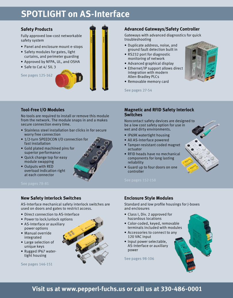
Safety ProductsFully approved low-cost networkable safety system • Panel and enclosure mount e-stops • Safety modules for gates, light
curtains, and perimeter guarding • Approved by NFPA, UL, and OSHA • Safe to Cat 4/ SIL 3
See pages 125-162
Advanced Gateways/Safety ControllerGateways with advanced diagnostics for quick troubleshooting • Duplicate address, noise, and
ground fault detection built in • RS232 port for diagnostic
monitoring of network • Advanced graphical display • Ethernet/IP support allows direct
integration with modern Allen-Bradley PLCs
• Removable memory card
See pages 27-54
Tool-Free I/O Modules No tools are required to install or remove this module from the network. The module snaps in and a makes secure connection every time.• Stainless steel installation bar clicks in for secure
worry free connection • 1/2-turn SPEEDCON I/O connection for
fast installation • Gold plated machined pins for
superior performance • Quick change top for easy
module swapping • Outputs with RED
overload indication right at each connector
See pages 78-81
New Safety Interlock SwitchesAS-Interface mechanical safety interlock switches are used on doors and gates to restrict access.• Direct connection to AS-Interface • Power to lock/unlock options • AS-Interface or auxiliary
power options • Manual override
integrated • Large selection of
unique keys• Rugged IP67 water-
tight housing
See pages 146-151
Enclosure Style ModulesStandard and low profile housings for J-boxes and enclosures • Class I, Div. 2 approved for
hazardous locations • Color-coded, keyed, removable
terminals included with modules • Accessories to connect to any
120 VAC input • Input power selectable,
AS-Interface or auxiliary power
See pages 98-106
Applications In:• Material handling, warehousing, and inventory control• Printing, labeling, sorting, bulk mailing, and inserting• Automotive and allied industries• Pharmaceutical & medical instrumentation• Factory automation & electronics
Handheld SolutionsPepperl+Fuchs handheld solutions are rugged, light weight, and feature full graphical displays. They are often used for inventory management, offline write stations and cordless tracking systems.• Read/write data to any P+F
or ISO standard RFID tag• Wireless• Full graphical display with
keyboard• Will read 1-D or 2-D bar codes• Includes RS-232 / PS2 / USB support
IDENTControl SolutionsPepperl+Fuchs offers a wide selection of RFID readers for factory automation. IDENTControl is unique because of it's metal housing, graphical display, and universal connectivity to low frequency, high frequency and microwave type read heads.• Metal housing IP67• Over 50 different tags available• 14 different read head styles• EtherNet/IP and DeviceNet connectivity • Modbus/TCP, TCP/IP, PROFINET,
PROFIBUS, RS-232 supported• Email notification / web page configuration• IDENTControl compact 1- and 2-channel
versions available
Need Help Solving a Tough Application?Pepperl+Fuchs wants to ensure that you receive the service and support you need when you need it, 24 hours every day. You can find CAD drawings, download product data sheets, or request free literature. Get it all on the web at www.pepperl-fuchs.us.
Need More? Ask an Expert.With a click of the mouse, you can get advice from engineers who are experts in AS-Interface technology, who are familiar with a wide range of applications, and who can help you solve your most challenging production requirements. For reliable advice, visit www.pepperl-fuchs.us/askfa and ask an expert.
Magnetic and RFID Safety Interlock SwitchesNoncontact safety devices are designed to be a low cost safety option for use in wet and dirty environments.• IP69K watertight housing • All AS-Interface powered • Tamper-resistant coded magnet
actuator• RFID heads have no mechanical
components for long lasting reliability
• Guard up to four doors on one controller
See pages 152-158

1
Introduction .............................................. 17Gateways and Scanners ............................ 27Power Supplies and Repeaters .................. 55I/O Modules .............................................. 71Safety Solutions ..................................... 125Intelligent Sensors .................................. 163Cordsets ................................................. 197Accessories ............................................ 211Appendix ................................................ 227
REFERENCE & BUYER'S GUIDEAS-INTERFACE PRODUCTS
Pepperl+Fuchs has been providing the highest-quality industrial sensors for nearly 60 years. We are the world’s largest sensor manufacturer, and we continue to set the standard by offering sensors that cover a vast range of applications, from the most basic to the most challenging. Pepperl+Fuchs’ sensors are crafted using state-of-the-art components and the latest technologies to ensure precision, reliability, and functionality.
Singapore: +65 6779 [email protected]
USA: +1 330 486 [email protected]
Germany: +49 621 [email protected]
Pepperl+Fuchs Groupwww.pepperl-fuchs.com
Subject to modifications without notice Copyright Pepperl+Fuchs
2
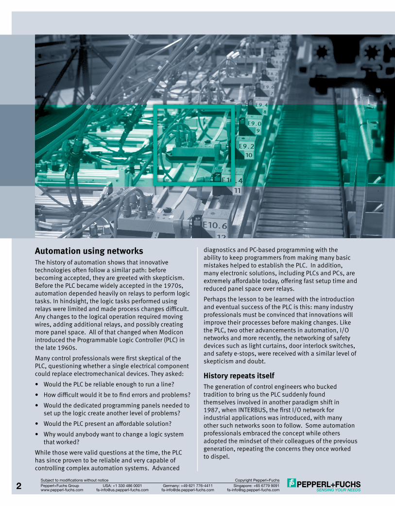
Automation using networksThe history of automation shows that innovative technologies often follow a similar path: before becoming accepted, they are greeted with skepticism. Before the PLC became widely accepted in the 1970s, automation depended heavily on relays to perform logic tasks. In hindsight, the logic tasks performed using relays were limited and made process changes difficult. Any changes to the logical operation required moving wires, adding additional relays, and possibly creating more panel space. All of that changed when Modicon introduced the Programmable Logic Controller (PLC) in the late 1960s.Many control professionals were first skeptical of the PLC, questioning whether a single electrical component could replace electromechanical devices. They asked:• Would the PLC be reliable enough to run a line?• How difficult would it be to find errors and problems?• Would the dedicated programming panels needed to
set up the logic create another level of problems?• Would the PLC present an affordable solution?• Why would anybody want to change a logic system
that worked?While those were valid questions at the time, the PLC has since proven to be reliable and very capable of controlling complex automation systems. Advanced
diagnostics and PC-based programming with the ability to keep programmers from making many basic mistakes helped to establish the PLC. In addition, many electronic solutions, including PLCs and PCs, are extremely affordable today, offering fast setup time and reduced panel space over relays.Perhaps the lesson to be learned with the introduction and eventual success of the PLC is this: many industry professionals must be convinced that innovations will improve their processes before making changes. Like the PLC, two other advancements in automation, I/O networks and more recently, the networking of safety devices such as light curtains, door interlock switches, and safety e-stops, were received with a similar level of skepticism and doubt.
History repeats itselfThe generation of control engineers who bucked tradition to bring us the PLC suddenly found themselves involved in another paradigm shift in 1987, when INTERBUS, the first I/O network for industrial applications was introduced, with many other such networks soon to follow. Some automation professionals embraced the concept while others adopted the mindset of their colleagues of the previous generation, repeating the concerns they once worked to dispel.
Singapore: +65 6779 [email protected]
USA: +1 330 486 [email protected]
Germany: +49 621 [email protected]
Pepperl+Fuchs Groupwww.pepperl-fuchs.com
Subject to modifications without notice Copyright Pepperl+Fuchs
2
3
• Would networked I/O be reliable enough to run a line?• How difficult would it be to find errors and problems?• Would the additional electronics needed to set up
the network just create another level of problems?• Would it be an affordable solution?• Why would anybody want to change an I/O system
that worked?Not only are these the same questions asked previously, but so are the answers. Of course, not every I/O network proposed at the time was able to address reliability concerns adequately, and some poorly designed solutions disappeared. Now, twenty years later, we know that well-designed I/O networks offer excellent reliability, and increased setup flexibility: the same features that aided the transition to PLCs. History had repeated itself.
Networks in the New MillenniumToday, a few networks stand out in terms of features and flexibility: PROFIBUS, CC-Link, DeviceNet, Ethernet, and AS-Interface. Those familiar with networks know that this network quintet dominates the world market with a combined strength of close to 40 million installed nodes! However, it is less well-known that AS-Interface stands out in a very important way: AS-Interface was designed not to compete with the others, but rather to enhance them. To understand how AS-Interface can work to improve these higher-level networks, it helps to compare automation networks with another movement system we are familiar with: human transportation systems.
Optimizing FlowMoving data is comparable to moving people around the country using various transportation systems. Traveling cross country might include: driving to the airport, boarding a plane, flying to another airport, and finally using another car to reach the destination. While some people prefer driving the entire distance, nobody expects an airline to pick them up at home and drop them off at their final destination. Therefore, we have become accustomed to being "repackaged" in various vehicles, and with other travelers. In other words: the traveler starts out on a system that allows small units to be transported quickly to a consolidator. Here units, arriving from all different directions are repackaged into larger packets, moved at high speed to another consolidator, and again taken apart and sent on their final leg of the trip. Clearly, this structured approach optimizes flow, reduces the time it takes to reach a destination, and increases efficiency.AS-Interface is the road system connecting highly distributed I/O to a data consolidator, handing it over to an upper-level network designed to handle
large amounts of data, which moves it to the PLC for processing and analysis. AS-Interface enhances networks such as DeviceNet because it collects I/O data to create large bundles, ensuring that it does not lose efficiency by transmitting a few data bits in its multibyte-size cargo space. PROFIBUS also works better because AS-Interface removes the stringent requirement of adhering to a single topology (daisy chain), allowing I/O to be placed anywhere needed. We call this topology-free networking. In its 15 year history, AS-Interface has become the accepted universal feeder system for data. With over 13 million field nodes, AS-Interface is well past the initial acceptance phase, having proven its effectiveness in a wide variety of applications. This Reference & Buyer’s Guide focuses on the many reasons for its success, including its flexibility and simplicity, exceptional noise immunity, availability of a full electromechanical installation system, and its low price point.
Networking SafetyToday, another relatively new and revolutionary idea in automation concerns the way safety devices are connected. The concept of transmitting safety data over a network, while technologically a huge step, is ultimately just another example of technological innovation in automation. PLCs replaced relay logic, networks replaced hardwired I/O, and networking safety devices will most certainly make hardwired safety a relic of our times. Again AS-Interface stands out, as the I/O network enhancing the functionality of upper level solutions. With AS-Interface Safety at Work–the base technology that allows AS-Interface to transmit safety data in applications up to Category 4 or Safety Integrity Level (SIL) 3–DeviceNet, PROFIBUS, CC-Link, and any industrial Ethernet can now benefit in more ways than ever from the flexibility and simplicity of AS-Interface.
The FutureIt is very difficult to predict what technological advances will shape the world of automation over the next decade. It is certainly not too early to recognize Ethernet as one of the technologies that will significantly influence the way control systems are designed and built. But irrespective of what the automation and networking future will hold, AS-Interface will surely be a part of it. As the only true, universal I/O level network, working flawlessly with all important upper-level solutions, addressing the most important demands of the automation market (broad support worldwide, excellent troubleshooting features, flexible installation, and low cost, to name just a few), it has all the great features needed to be the preferred partner for today’s and tomorrow’s automation networks.
Singapore: +65 6779 [email protected]
USA: +1 330 486 [email protected]
Germany: +49 621 [email protected]
Pepperl+Fuchs Groupwww.pepperl-fuchs.com
Subject to modifications without notice Copyright Pepperl+Fuchs
3
Singapore: +65 6779 [email protected]
USA: +1 330 486 [email protected]
Germany: +49 621 [email protected]
Pepperl+Fuchs Groupwww.pepperl-fuchs.com
Subject to modifications without notice Copyright Pepperl+Fuchs4
AS-INTERFACE
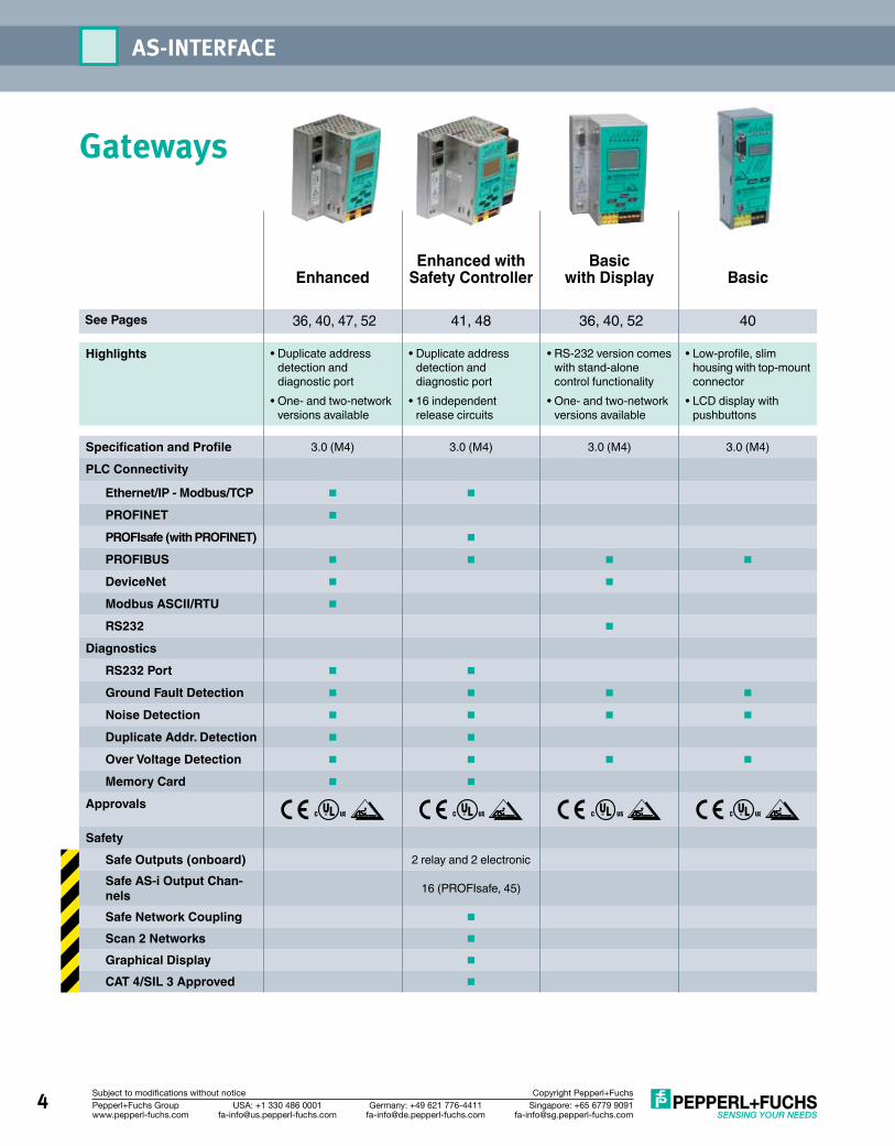
Gateways
EnhancedEnhanced with
Safety ControllerBasic
with Display Basic
See Pages 36, 40, 47, 52 41, 48 36, 40, 52 40
Highlights • Duplicate address detection and diagnostic port
• One- and two-network versions available
• Duplicate address detection and diagnostic port
• 16 independent release circuits
• RS-232 version comes with stand-alone control functionality
• One- and two-network versions available
• Low-profile, slim housing with top-mount connector
• LCD display with pushbuttons
Specification and Profile 3.0 (M4) 3.0 (M4) 3.0 (M4) 3.0 (M4)
PLC Connectivity
Ethernet/IP - Modbus/TCP n n
PROFINET n
PROFIsafe (with PROFINET) n
PROFIBUS n n n n
DeviceNet n n
Modbus ASCII/RTU n
RS232 n
DiagnosticsRS232 Port n n
Ground Fault Detection n n n n
Noise Detection n n n n
Duplicate Addr. Detection n n
Over Voltage Detection n n n n
Memory Card n n
Approvals
SafetySafe Outputs (onboard) 2 relay and 2 electronic
Safe AS-i Output Chan-nels 16 (PROFIsafe, 45)
Safe Network Coupling n
Scan 2 Networks n
Graphical Display n
CAT 4/SIL 3 Approved n
Singapore: +65 6779 [email protected]
USA: +1 330 486 [email protected]
Germany: +49 621 [email protected]
Pepperl+Fuchs Groupwww.pepperl-fuchs.com
Subject to modifications without notice Copyright Pepperl+Fuchs 5
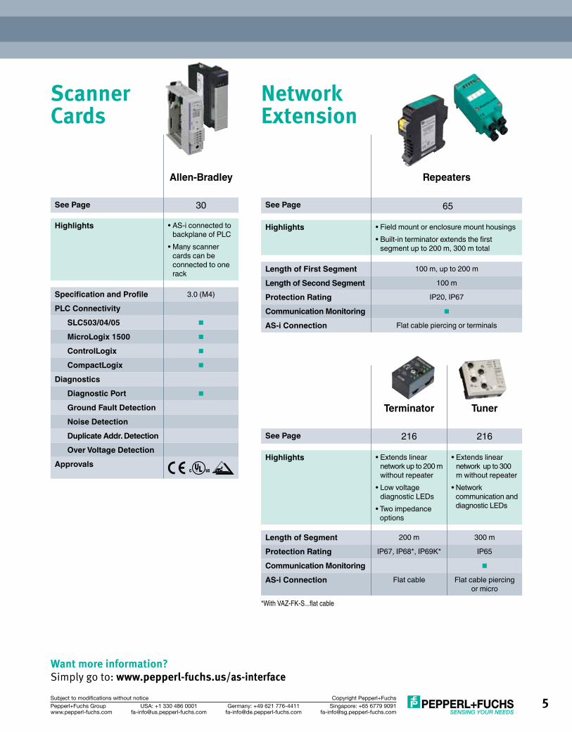
Scanner Cards
Network Extension
Want more information? Simply go to: www.pepperl-fuchs.us/as-interface
Allen-Bradley
See Page 30
Highlights • AS-i connected to backplane of PLC
• Many scanner cards can be connected to one rack
Specification and Profile 3.0 (M4)
PLC ConnectivitySLC503/04/05 n
MicroLogix 1500 n
ControlLogix n
CompactLogix n
DiagnosticsDiagnostic Port n
Ground Fault DetectionNoise DetectionDuplicate Addr. DetectionOver Voltage Detection
Approvals
Repeaters
See Page 65
Highlights • Field mount or enclosure mount housings• Built-in terminator extends the first
segment up to 200 m, 300 m total
Length of First Segment 100 m, up to 200 m
Length of Second Segment 100 m
Protection Rating IP20, IP67
Communication Monitoring n
AS-i Connection Flat cable piercing or terminals
Terminator Tuner
See Page 216 216
Highlights • Extends linear network up to 200 m without repeater
• Low voltage diagnostic LEDs
• Two impedance options
• Extends linear network up to 300 m without repeater
• Network communication and diagnostic LEDs
Length of Segment 200 m 300 m
Protection Rating IP67, IP68*, IP69K* IP65
Communication Monitoring n
AS-i Connection Flat cable Flat cable piercing or micro
*With VAZ-FK-S...flat cable
Singapore: +65 6779 [email protected]
USA: +1 330 486 [email protected]
Germany: +49 621 [email protected]
Pepperl+Fuchs Groupwww.pepperl-fuchs.com
Subject to modifications without notice Copyright Pepperl+Fuchs6
AS-INTERFACE
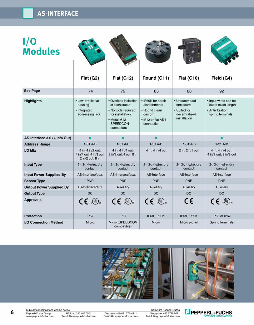
I/O Modules
Flat (G2)
Flat (G12)
Round (G11) Flat (G10) Field (G4)
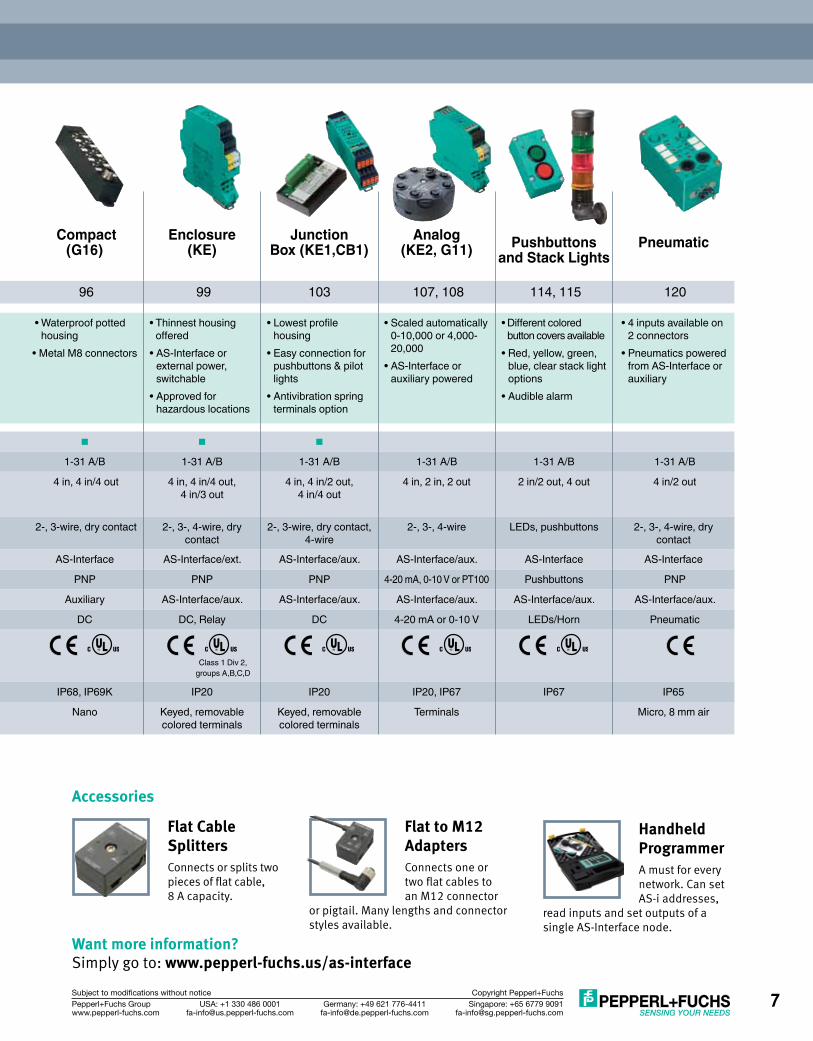
Compact (G16)
Enclosure (KE)
Junction Box (KE1,CB1)
Analog (KE2, G11)
Pushbuttons
and Stack LightsPneumatic
See Page 74 79 83 88 92 96 99 103 107, 108 114, 115 120
Highlights • Low-profile flat housing
• Integrated addressing jack
• Overload indication at each output
• No tools required for installation
• Metal M12 SPEEDCON connectors
• IP69K for harsh environments
• Round clean design
• M12 or flat AS-i connection
• Ultracompact enclosure
• Suited for decentralized installation
• Input wires can be cut to exact length
• Antivibration spring terminals
• Waterproof potted housing
• Metal M8 connectors
• Thinnest housing offered
• AS-Interface or external power, switchable
• Approved for hazardous locations
• Lowest profile housing
• Easy connection for pushbuttons & pilot lights
• Antivibration spring terminals option
• Scaled automatically 0-10,000 or 4,000-20,000
• AS-Interface or auxiliary powered
• Different colored button covers available
• Red, yellow, green, blue, clear stack light options
• Audible alarm
• 4 inputs available on 2 connectors
• Pneumatics powered from AS-Interface or auxiliary
AS-Interface 3.0 (4 In/4 Out) n n n n n n n
Address Range 1-31 A/B 1-31 A/B 1-31 A/B 1-31 A/B 1-31 A/B 1-31 A/B 1-31 A/B 1-31 A/B 1-31 A/B 1-31 A/B 1-31 A/B
I/O Mix 4 in, 4 in/2 out, 4 in/4 out, 4 in/3 out,
2 in/2 out, 8 in
4 in, 4 in/4 out, 2 in/2 out, 4 out, 8 in
4 in, 4 in/4 out 2 in, 2in/1 out 4 in, 4 in/4 out, 4 in/3 out, 2 in/2 out
4 in, 4 in/4 out 4 in, 4 in/4 out, 4 in/3 out
4 in, 4 in/2 out, 4 in/4 out
4 in, 2 in, 2 out 2 in/2 out, 4 out 4 in/2 out
Input Type 2-, 3-, 4-wire, dry contact
2-, 3-, 4-wire, dry contact
2-, 3-, 4-wire, dry contact
2-, 3-, 4-wire, dry contact
2-, 3-, 4-wire, dry contact
2-, 3-wire, dry contact 2-, 3-, 4-wire, dry contact
2-, 3-wire, dry contact, 4-wire
2-, 3-, 4-wire LEDs, pushbuttons 2-, 3-, 4-wire, dry contact
Input Power Supplied By AS-Interface/aux. AS-Interface/aux. AS-Interface AS-Interface AS-Interface AS-Interface AS-Interface/ext. AS-Interface/aux. AS-Interface/aux. AS-Interface AS-Interface
Sensor Type PNP PNP PNP PNP PNP PNP PNP PNP 4-20 mA, 0-10 V or PT100 Pushbuttons PNP
Output Power Supplied By AS-Interface/aux. Auxiliary Auxiliary Auxiliary Auxiliary Auxiliary AS-Interface/aux. AS-Interface/aux. AS-Interface/aux. AS-Interface/aux. AS-Interface/aux.
Output Type DC DC DC DC DC DC DC, Relay DC 4-20 mA or 0-10 V LEDs/Horn Pneumatic
Approvals
Class 1 Div 2, groups A,B,C,D
Protection IP67 IP67 IP68, IP69K IP68, IP69K IP65 or IP67 IP68, IP69K IP20 IP20 IP20, IP67 IP67 IP65
I/O Connection Method Micro Micro (SPEEDCON compatible)
Micro Micro pigtail Spring terminals Nano Keyed, removable colored terminals
Keyed, removable colored terminals
Terminals Micro, 8 mm air
Singapore: +65 6779 [email protected]
USA: +1 330 486 [email protected]
Germany: +49 621 [email protected]
Pepperl+Fuchs Groupwww.pepperl-fuchs.com
Subject to modifications without notice Copyright Pepperl+Fuchs 7
Flat (G2)
Flat (G12)
Round (G11) Flat (G10) Field (G4)
Compact (G16)
Enclosure (KE)
Junction Box (KE1,CB1)
Analog (KE2, G11)
Pushbuttons
and Stack LightsPneumatic
See Page 74 79 83 88 92 96 99 103 107, 108 114, 115 120
Highlights • Low-profile flat housing
• Integrated addressing jack
• Overload indication at each output
• No tools required for installation
• Metal M12 SPEEDCON connectors
• IP69K for harsh environments
• Round clean design
• M12 or flat AS-i connection
• Ultracompact enclosure
• Suited for decentralized installation
• Input wires can be cut to exact length
• Antivibration spring terminals
• Waterproof potted housing
• Metal M8 connectors
• Thinnest housing offered
• AS-Interface or external power, switchable
• Approved for hazardous locations
• Lowest profile housing
• Easy connection for pushbuttons & pilot lights
• Antivibration spring terminals option
• Scaled automatically 0-10,000 or 4,000-20,000
• AS-Interface or auxiliary powered
• Different colored button covers available
• Red, yellow, green, blue, clear stack light options
• Audible alarm
• 4 inputs available on 2 connectors
• Pneumatics powered from AS-Interface or auxiliary
AS-Interface 3.0 (4 In/4 Out) n n n n n n n
Address Range 1-31 A/B 1-31 A/B 1-31 A/B 1-31 A/B 1-31 A/B 1-31 A/B 1-31 A/B 1-31 A/B 1-31 A/B 1-31 A/B 1-31 A/B
I/O Mix 4 in, 4 in/2 out, 4 in/4 out, 4 in/3 out,
2 in/2 out, 8 in
4 in, 4 in/4 out, 2 in/2 out, 4 out, 8 in
4 in, 4 in/4 out 2 in, 2in/1 out 4 in, 4 in/4 out, 4 in/3 out, 2 in/2 out
4 in, 4 in/4 out 4 in, 4 in/4 out, 4 in/3 out
4 in, 4 in/2 out, 4 in/4 out
4 in, 2 in, 2 out 2 in/2 out, 4 out 4 in/2 out
Input Type 2-, 3-, 4-wire, dry contact
2-, 3-, 4-wire, dry contact
2-, 3-, 4-wire, dry contact
2-, 3-, 4-wire, dry contact
2-, 3-, 4-wire, dry contact
2-, 3-wire, dry contact 2-, 3-, 4-wire, dry contact
2-, 3-wire, dry contact, 4-wire
2-, 3-, 4-wire LEDs, pushbuttons 2-, 3-, 4-wire, dry contact
Input Power Supplied By AS-Interface/aux. AS-Interface/aux. AS-Interface AS-Interface AS-Interface AS-Interface AS-Interface/ext. AS-Interface/aux. AS-Interface/aux. AS-Interface AS-Interface
Sensor Type PNP PNP PNP PNP PNP PNP PNP PNP 4-20 mA, 0-10 V or PT100 Pushbuttons PNP
Output Power Supplied By AS-Interface/aux. Auxiliary Auxiliary Auxiliary Auxiliary Auxiliary AS-Interface/aux. AS-Interface/aux. AS-Interface/aux. AS-Interface/aux. AS-Interface/aux.
Output Type DC DC DC DC DC DC DC, Relay DC 4-20 mA or 0-10 V LEDs/Horn Pneumatic
Approvals
Class 1 Div 2, groups A,B,C,D
Protection IP67 IP67 IP68, IP69K IP68, IP69K IP65 or IP67 IP68, IP69K IP20 IP20 IP20, IP67 IP67 IP65
I/O Connection Method Micro Micro (SPEEDCON compatible)
Micro Micro pigtail Spring terminals Nano Keyed, removable colored terminals
Keyed, removable colored terminals
Terminals Micro, 8 mm air
Want more information? Simply go to: www.pepperl-fuchs.us/as-interface
Accessories
Flat Cable SplittersConnects or splits two pieces of flat cable, 8 A capacity.
Flat to M12 AdaptersConnects one or two flat cables to an M12 connector
or pigtail. Many lengths and connector styles available.
Handheld ProgrammerA must for every network. Can set AS-i addresses,
read inputs and set outputs of a single AS-Interface node.
Singapore: +65 6779 [email protected]
USA: +1 330 486 [email protected]
Germany: +49 621 [email protected]
Pepperl+Fuchs Groupwww.pepperl-fuchs.com
Subject to modifications without notice Copyright Pepperl+Fuchs8
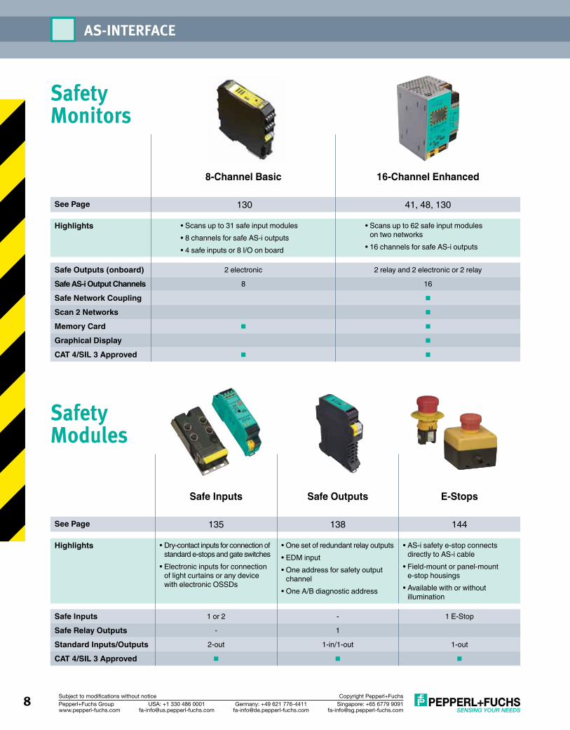
Safe Inputs Safe Outputs E-Stops
See Page 135 138 144
Highlights • Dry-contact inputs for connection of standard e-stops and gate switches
• Electronic inputs for connection of light curtains or any device with electronic OSSDs
• One set of redundant relay outputs• EDM input• One address for safety output
channel• One A/B diagnostic address
• AS-i safety e-stop connects directly to AS-i cable
• Field-mount or panel-mount e-stop housings
• Available with or without illumination
Safe Inputs 1 or 2 - 1 E-Stop
Safe Relay Outputs - 1
Standard Inputs/Outputs 2-out 1-in/1-out 1-out
CAT 4/SIL 3 Approved n n n
8-Channel Basic 16-Channel Enhanced
See Page 130 41, 48, 130
Highlights • Scans up to 31 safe input modules• 8 channels for safe AS-i outputs• 4 safe inputs or 8 I/O on board
• Scans up to 62 safe input modules on two networks
• 16 channels for safe AS-i outputs
Safe Outputs (onboard) 2 electronic 2 relay and 2 electronic or 2 relay
Safe AS-i Output Channels 8 16
Safe Network Coupling n
Scan 2 Networks n
Memory Card n n
Graphical Display n
CAT 4/SIL 3 Approved n n
Safety Modules
Safety Monitors
AS-INTERFACE
Singapore: +65 6779 [email protected]
USA: +1 330 486 [email protected]
Germany: +49 621 [email protected]
Pepperl+Fuchs Groupwww.pepperl-fuchs.com
Subject to modifications without notice Copyright Pepperl+Fuchs 9
Want more information? Simply go to: www.pepperl-fuchs.us/as-interface
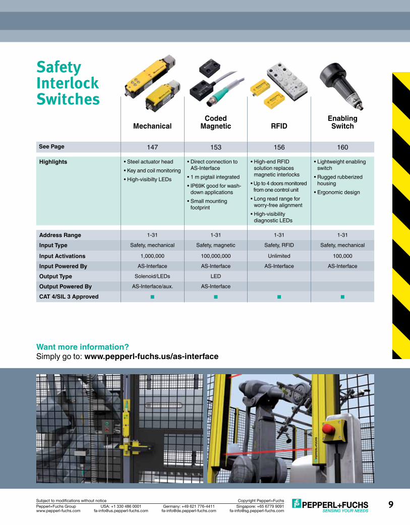
Safety Interlock Switches
Mechanical
Coded Magnetic
RFID
Enabling Switch
See Page 147 153 156 160
Highlights • Steel actuator head• Key and coil monitoring• High-visibilty LEDs
• Direct connection to AS-Interface
• 1 m pigtail integrated• IP69K good for wash-
down applications• Small mounting
footprint
• High-end RFID solution replaces magnetic interlocks
• Up to 4 doors monitored from one control unit
• Long read range for worry-free alignment
• High-visibility diagnostic LEDs
• Lightweight enabling switch
• Rugged rubberized housing
• Ergonomic design
Address Range 1-31 1-31 1-31 1-31
Input Type Safety, mechanical Safety, magnetic Safety, RFID Safety, mechanical
Input Activations 1,000,000 100,000,000 Unlimited 100,000
Input Powered By AS-Interface AS-Interface AS-Interface AS-Interface
Output Type Solenoid/LEDs LED
Output Powered By AS-Interface/aux. AS-Interface
CAT 4/SIL 3 Approved n n n n
Singapore: +65 6779 [email protected]
USA: +1 330 486 [email protected]
Germany: +49 621 [email protected]
Pepperl+Fuchs Groupwww.pepperl-fuchs.com
Subject to modifications without notice Copyright Pepperl+Fuchs10
AS-INTERFACE
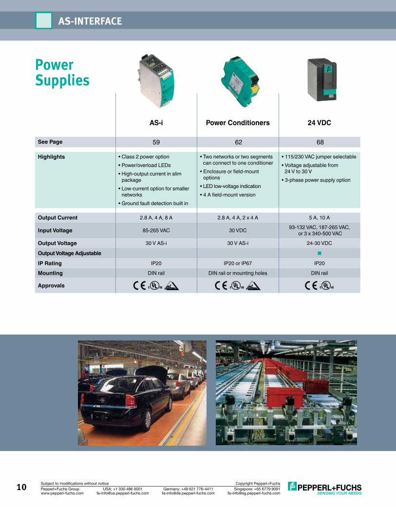
Power Supplies
AS-i Power Conditioners 24 VDC
See Page 59 62 68
Highlights • Class 2 power option• Power/overload LEDs• High-output current in slim
package• Low-current option for smaller
networks• Ground fault detection built in
• Two networks or two segments can connect to one conditioner
• Enclosure or field-mount options
• LED low-voltage indication• 4 A field-mount version
• 115/230 VAC jumper selectable• Voltage adjustable from
24 V to 30 V• 3-phase power supply option
Output Current 2.8 A, 4 A, 8 A 2.8 A, 4 A, 2 x 4 A 5 A, 10 A
Input Voltage 85-265 VAC 30 VDC 93-132 VAC, 187-265 VAC, or 3 x 340-500 VAC
Output Voltage 30 V AS-i 30 V AS-i 24-30 VDC
Output Voltage Adjustable n
IP Rating IP20 IP20 or IP67 IP20
Mounting DIN rail DIN rail or mounting holes DIN rail
Approvals
Singapore: +65 6779 [email protected]
USA: +1 330 486 [email protected]
Germany: +49 621 [email protected]
Pepperl+Fuchs Groupwww.pepperl-fuchs.com
Subject to modifications without notice Copyright Pepperl+Fuchs 11
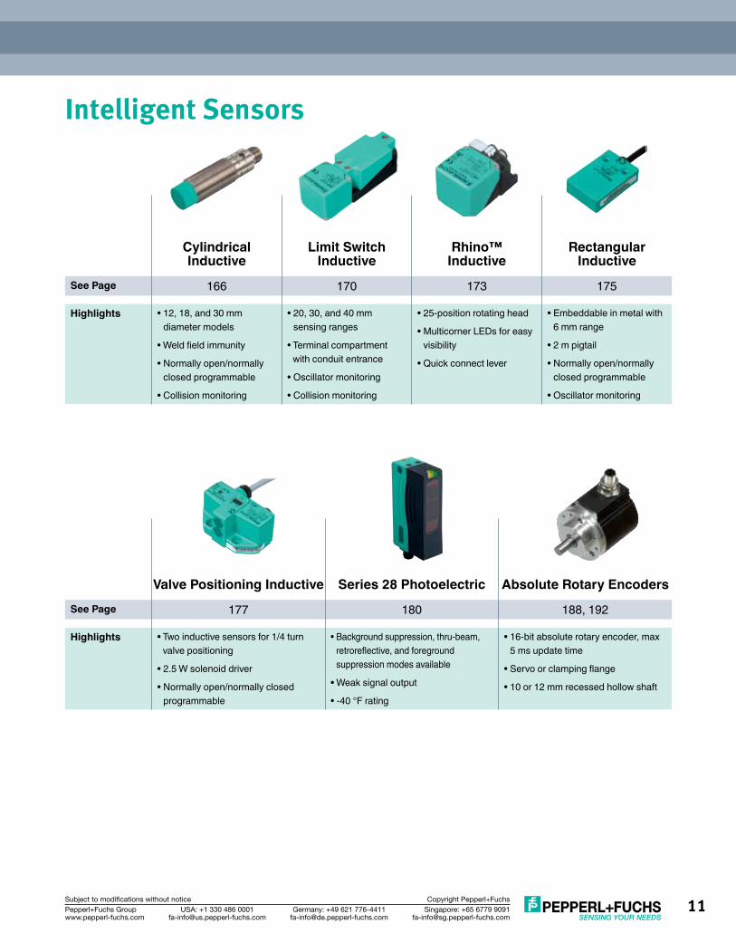
Intelligent Sensors
Cylindrical Inductive
Limit Switch Inductive
Rhino™ Inductive
Rectangular Inductive
See Page 166 170 173 175
Highlights • 12, 18, and 30 mm diameter models
• Weld field immunity
• Normally open/normally closed programmable
• Collision monitoring
• 20, 30, and 40 mm sensing ranges
• Terminal compartment with conduit entrance
• Oscillator monitoring
• Collision monitoring
• 25-position rotating head
• Multicorner LEDs for easy visibility
• Quick connect lever
• Embeddable in metal with 6 mm range
• 2 m pigtail
• Normally open/normally closed programmable
• Oscillator monitoring
Valve Positioning Inductive Series 28 Photoelectric Absolute Rotary EncodersSee Page 177 180 188, 192
Highlights • Two inductive sensors for 1/4 turn valve positioning
• 2.5 W solenoid driver
• Normally open/normally closed programmable
• Background suppression, thru-beam, retroreflective, and foreground suppression modes available
• Weak signal output
• -40 °F rating
• 16-bit absolute rotary encoder, max 5 ms update time
• Servo or clamping flange
• 10 or 12 mm recessed hollow shaft
Singapore: +65 6779 [email protected]
USA: +1 330 486 [email protected]
Germany: +49 621 [email protected]
Pepperl+Fuchs Groupwww.pepperl-fuchs.com
Subject to modifications without notice Copyright Pepperl+Fuchs12
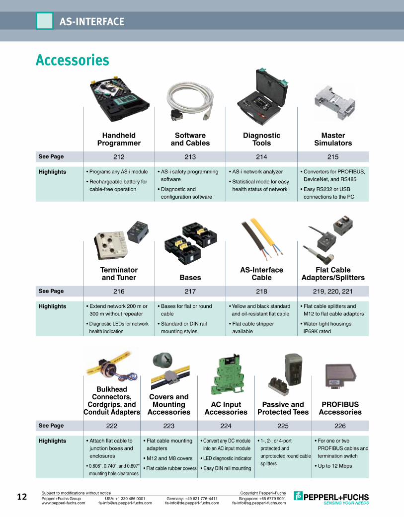
Accessories
Handheld Programmer
Software and Cables
Diagnostic Tools
Master Simulators
See Page 212 213 214 215
Highlights • Programs any AS-i module
• Rechargeable battery for cable-free operation
• AS-i safety programming software
• Diagnostic and configuration software
• AS-i network analyzer
• Statistical mode for easy health status of network
• Converters for PROFIBUS, DeviceNet, and RS485
• Easy RS232 or USB connections to the PC
Terminator and Tuner Bases
AS-Interface Cable
Flat Cable Adapters/Splitters
See Page 216 217 218 219, 220, 221
Highlights • Extend network 200 m or 300 m without repeater
• Diagnostic LEDs for network health indication
• Bases for flat or round cable
• Standard or DIN rail mounting styles
• Yellow and black standard and oil-resistant flat cable
• Flat cable stripper available
• Flat cable splitters and M12 to flat cable adapters
• Water-tight housings IP69K rated
Bulkhead Connectors,
Cordgrips, and Conduit Adapters
Covers and Mounting
AccessoriesAC Input
AccessoriesPassive and
Protected TeesPROFIBUS
AccessoriesSee Page 222 223 224 225 226
Highlights • Attach flat cable to junction boxes and enclosures
• 0.606", 0.740", and 0.807" mounting hole clearances
• Flat cable mounting adapters
• M12 and M8 covers
• Flat cable rubber covers
• Convert any DC module into an AC input module
• LED diagnostic indicator
• Easy DIN rail mounting
• 1-, 2-, or 4-port protected and unprotected round cable splitters
• For one or two PROFIBUS cables and termination switch
• Up to 12 Mbps
AS-INTERFACE

Singapore: +65 6779 [email protected]
USA: +1 330 486 [email protected]
Germany: +49 621 [email protected]
Pepperl+Fuchs Groupwww.pepperl-fuchs.com
Subject to modifications without notice Copyright Pepperl+Fuchs 13
MARKETS AND APPLICATIONS
Material handling applications demand fast and reliable networks. AS-Interface is a fast and dependable discrete I/O network designed to help you stay competitive and increase profitability in the new global economy. AS-Interface reduces the total cost of ownership for OEMs, as well as increasing productivity and safety for end users.
AS-Interface for the Material Handling Industry
n Reduced cable cost and enclosure size n Reduced installation and wiring time n Communication through slip ringsn Faster machine commissioning/post commissioningn Easy field system expansionn Networking safety components and devices on one cable

Singapore: +65 6779 [email protected]
USA: +1 330 486 [email protected]
Germany: +49 621 [email protected]
Pepperl+Fuchs Groupwww.pepperl-fuchs.com
Subject to modifications without notice Copyright Pepperl+Fuchs14
AS-Interface for the Automotive Industry
The automotive industry demands equipment that supports lean, flexible manufacturing. Pepperl-Fuchs’ AS-Interface meets this challenge by providing speed, simplicity, and reliability in I/O networking.
n Reduced cost (smaller PLC rack, less wire, smaller panel, and fewer I/O cards)
n Fast I/O exchange on robots and end effectorsn Increased system availability and safety
system uptimen Reduced installation and maintenance time
MARKETS AND APPLICATIONS

Singapore: +65 6779 [email protected]
USA: +1 330 486 [email protected]
Germany: +49 621 [email protected]
Pepperl+Fuchs Groupwww.pepperl-fuchs.com
Subject to modifications without notice Copyright Pepperl+Fuchs 15
PackagingChangeover and uptime maximization are the name of the game in packaging. AS-Interface keeps networks simple, versatile, and ready to respond to changing demands. From flow wrappers to palletizers, AS-Interface connects all modular components together. In the dynamic world of packaging, AS-Interface just makes sense.
AS-Interface for the Packaging and Printing Industries
n Simplified machine guarding (Safety at Work: SaW)
n Fast modular machine setup and changeover
n Superior diagnostics enable efficient and fast troubleshooting
n Fast I/O updates support high-speed packaging
n Rugged housings hold up to messy packaging materials
PrintingThe printing/converting industries require heavy-duty, flexible equipment to get the job done right and on time. If your application requires high-speed operation, excellent diagnostic features, optimum cost-effectiveness, and safety device monitoring, you simply won’t find a better solution than Pepperl+Fuchs’ AS-Interface discrete I/O system.
n Reduced wiring saves time and cabinet space n Diagnostic monitoring decreases downtimen Simplified safety device monitoring via
Safety at Work (SaW)
Singapore: +65 6779 [email protected]
USA: +1 330 486 [email protected]
Germany: +49 621 [email protected]
Pepperl+Fuchs Groupwww.pepperl-fuchs.com
Subject to modifications without notice Copyright Pepperl+Fuchs16
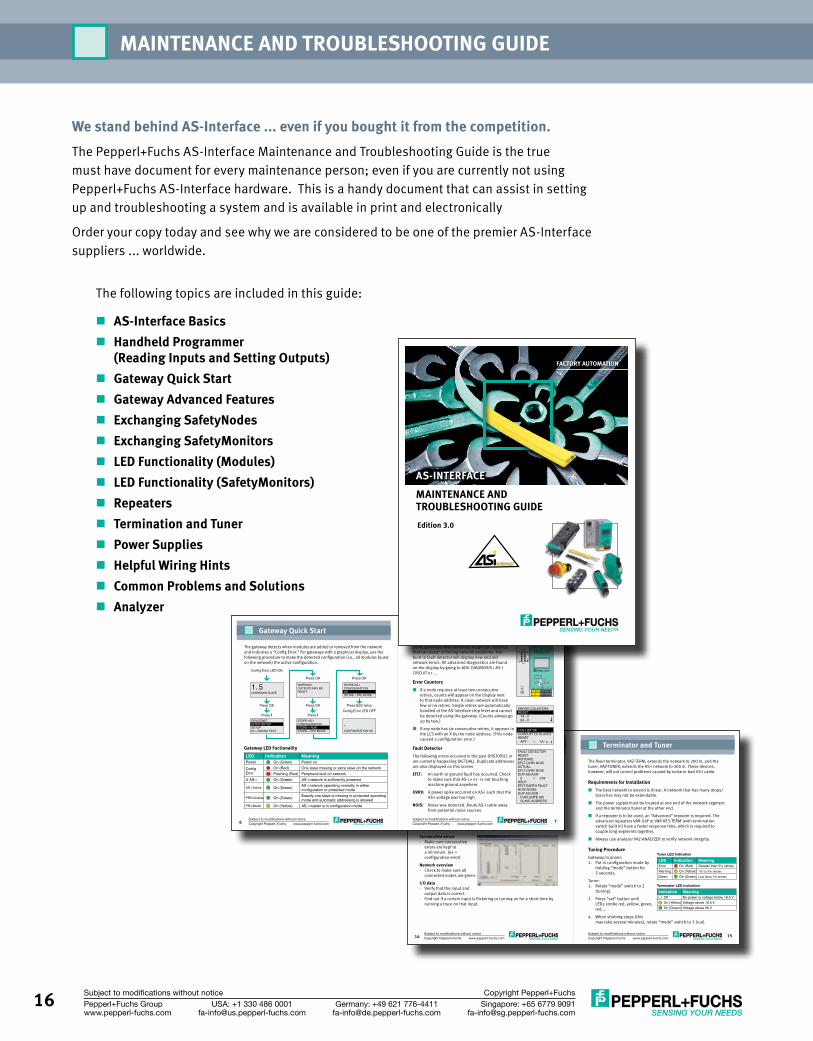
We stand behind AS-Interface ... even if you bought it from the competition.The Pepperl+Fuchs AS-Interface Maintenance and Troubleshooting Guide is the true must have document for every maintenance person; even if you are currently not using Pepperl+Fuchs AS-Interface hardware. This is a handy document that can assist in setting up and troubleshooting a system and is available in print and electronically
Order your copy today and see why we are considered to be one of the premier AS-Interface suppliers ... worldwide.
The following topics are included in this guide:
n AS-Interface Basicsn Handheld Programmer
(Reading Inputs and Setting Outputs)n Gateway Quick Startn Gateway Advanced Featuresn Exchanging SafetyNodesn Exchanging SafetyMonitorsn LED Functionality (Modules)n LED Functionality (SafetyMonitors)n Repeatersn Termination and Tunern Power Suppliesn Helpful Wiring Hintsn Common Problems and Solutionsn Analyzer
MAINTENANCE AND TROUBLESHOOTING GUIDE
www.pepperl-fuchs.comSubject to modifications without noticeCopyright Pepperl+Fuchs www.pepperl-fuchs.com
Subject to modifications without noticeCopyright Pepperl+Fuchs14 15
Analyzer
The network analyzer, VAZ-ANALYZER, provides information about network stability and allows detailed analysis of protocol-specific communication detail.
There are two modes of operation. The first is online statistics where the overall health of the network is read. The second is trace mode where individual AS-i telegrams are recorded, filtered, and viewed for later analysis. This mode is often used to track down specific input, output or timing problems.
Online StatisticsAdvance statistics (check for)- Little or no missing telegrams- No slave telegrams without master call
Consecutive errors- Make sure consecutive
errors are kept to a minimum. (6x = configuration error)
Network overview- Check to make sure all
connected nodes are green.
I/O data- Verify that the input and
output data is correct.- Find out if a certain input is flickering or turning on for a short time by
running a trace on that input.
Terminator and Tuner
The fixed terminator, VAZ-TERM, extends the network to 200 m, and the tuner, VAZ-TUNER, extends the AS-i network to 300 m. These devices, however, will not correct problems caused by noise or bad AS-i cable.
Requirements for Installation¢ The best network to extend is linear. A network that has many drops/
branches may not be extendable.
¢ The power supply must be located at one end of the network segment and the terminator/tuner at the other end.
¢ If a repeater is to be used, an “Advanced” repeater is required. The advanced repeaters VAR-G4F or VAR-KE3-TERM (with termination switch built in) have a faster response time, which is required to couple long segments together.
¢ Always use analyzer VAZ-ANALYZER to verify network integrity.
Tuning ProcedureGateway/scanner:1. Put in configuration mode by
holding “mode” button for 5 seconds.
Tuner:1. Rotate “mode” switch to 2
(tuning).
2. Press “set” button until LEDs strobe red, yellow, green, red....
4. When strobing stops (this may take several minutes), rotate “mode” switch to 3 (run).
Tuner LED Indication
LED Indication MeaningError On (Red) Greater than 5% retriesWarning On (Yellow) 1% to 5% retries
Green On (Green) Less than 1% retries
Terminator LED Indication
Indication MeaningOff No power or voltage below 18.5 VOn (Yellow) Voltage above 18.5 VOn (Green) Voltage above 26 V
www.pepperl-fuchs.comSubject to modifications without noticeCopyright Pepperl+Fuchs www.pepperl-fuchs.com
Subject to modifications without noticeCopyright Pepperl+Fuchs6 7
Gateway Quick Start
Gateway LED FuctionalityLED Indication MeaningPower On (Green) Power onConfig Error
On (Red) One slave missing or extra slave on the networkFlashing (Red) Peripheral fault on network
U AS-i On (Green) AS-i network is sufficiently powered
AS-i Active On (Green) AS-i network operating normally in either configuration or protected mode
PRG Enable On (Green) Exactly one slave is missing in protected operating mode and automatic addressing is allowed
PRJ Mode On (Yellow) AS-i master is in configuration mode
DEVICENETQUICK SETUPSETUPIO + PARAM. TEST
1. 5 WARNING:OUTPUTS MAY BE RESET
STORE AS-ICONFIGURATIONSTORE + RUNSTORE + PRJ MODE
STORE AS-ICONFIGURATIONOKSTORE + PRJ MODE
CONFIGURATION OK
.
Press OK
Press
Press OK
Press OK
Press
Press OK
Press ESC twice
Config Error LED ON
Config Error LED OFF
The gateway detects when modules are added or removed from the network and indicates a “Config Error.” For gateways with a graphical display, use the following procedure to make the detected configuration (i.e., all modules found on the network) the active configuration.
Gateway Advanced Features
Some gateways have advanced diagnostic features that can assist in finding network problems. The built-in fault detector will display new and old network errors. All advanced diagnostics are found on the display by going to ADV. DIAGNOSIS > AS-I CIRCUIT x > ...
Error Counters¢ If a node requires at least two consecutive
retries, counts will appear on the display next to that node address. A clean network will have few or no retries. Single retries are automatically handled at the AS-Interface chip level and cannot be detected using the gateway. (Counts always go up by two.)
¢ If any node has six consecutive retries, it appears in the LCS with an X by the node address. (This node caused a configuration error.)
Fault DetectorThe following errors occurred in the past (HISTORIC) or are currently happening (ACTUAL). Duplicate addresses are also displayed on this screen.
EFLT: An earth or ground fault has occurred. Check to make sure that AS-i + or - is not touching machine ground anywhere.
OVRV: A power spike occurred on AS-i such that the AS-i voltage was too high.
NOIS: Noise was detected. Route AS-i cable away from potential noise sources.
ERROR COUNTERSRESET
1A - 02A - 0
LCS LIST OFCORRUPTED SLAVESRESET
APF - I 1A - x
FAULT DETECTORRESETHISTORIC:EFLT OVRV NOISACTUAL:EFLT OVRV NOISDUP ASI ADR:
0 I 31BHELP:EFLT EARTH FAULTNOIS NOISEDUP ASI ADR
DUPLICATE ASISLAVE ADDRESS
POWERMNS
CONFIG ERR
U AS-iAS-i A
CTIVE
PRG ENABLE
PRJ MODE
RS 232
+ASI- +ASI- NC NC+PWR-ASI
OKESCMode
Set
UNKNOWN SLAVE
MAINTENANCE AND TROUBLESHOOTING GUIDEEdition 3.0
FACTORY AUTOMATION
AS-INTERFACE
17Singapore: +65 6779 [email protected]
USA: +1 330 486 [email protected]
Germany: +49 621 [email protected]
Pepperl+Fuchs Groupwww.pepperl-fuchs.com
Subject to modifications without notice Copyright Pepperl+Fuchs
Introduction AS-Interface
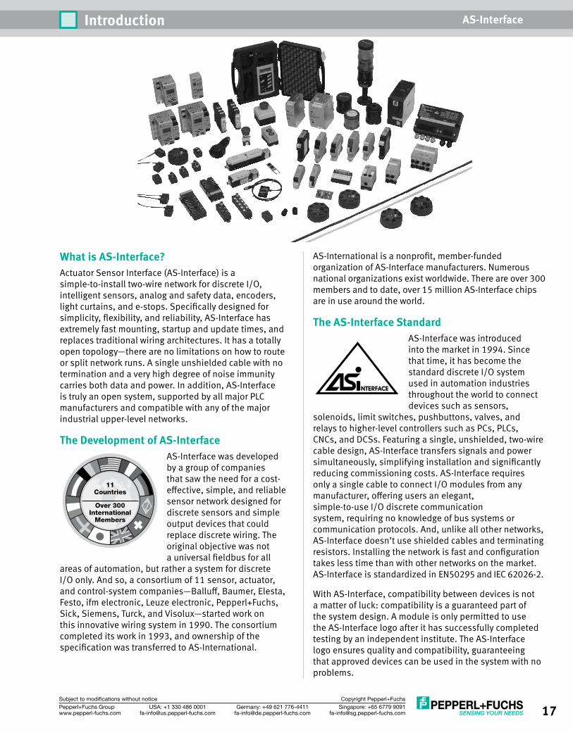
AS-International is a nonprofit, member-funded organization of AS-Interface manufacturers. Numerous national organizations exist worldwide. There are over 300 members and to date, over 15 million AS-Interface chips are in use around the world.
The AS-Interface StandardAS-Interface was introduced into the market in 1994. Since that time, it has become the standard discrete I/O system used in automation industries throughout the world to connect devices such as sensors,
solenoids, limit switches, pushbuttons, valves, and relays to higher-level controllers such as PCs, PLCs, CNCs, and DCSs. Featuring a single, unshielded, two-wire cable design, AS-Interface transfers signals and power simultaneously, simplifying installation and significantly reducing commissioning costs. AS-Interface requires only a single cable to connect I/O modules from any manufacturer, offering users an elegant, simple-to-use I/O discrete communication system, requiring no knowledge of bus systems or communication protocols. And, unlike all other networks, AS-Interface doesn’t use shielded cables and terminating resistors. Installing the network is fast and configuration takes less time than with other networks on the market. AS-Interface is standardized in EN50295 and IEC 62026-2.
With AS-Interface, compatibility between devices is not a matter of luck: compatibility is a guaranteed part of the system design. A module is only permitted to use the AS-Interface logo after it has successfully completed testing by an independent institute. The AS-Interface logo ensures quality and compatibility, guaranteeing that approved devices can be used in the system with no problems.
What is AS-Interface?Actuator Sensor Interface (AS-Interface) is a simple-to-install two-wire network for discrete I/O, intelligent sensors, analog and safety data, encoders, light curtains, and e-stops. Specifically designed for simplicity, flexibility, and reliability, AS-Interface has extremely fast mounting, startup and update times, and replaces traditional wiring architectures. It has a totally open topology—there are no limitations on how to route or split network runs. A single unshielded cable with no termination and a very high degree of noise immunity carries both data and power. In addition, AS-Interface is truly an open system, supported by all major PLC manufacturers and compatible with any of the major industrial upper-level networks.
The Development of AS-InterfaceAS-Interface was developed by a group of companies that saw the need for a cost-effective, simple, and reliable sensor network designed for discrete sensors and simple output devices that could replace discrete wiring. The original objective was not a universal fieldbus for all
areas of automation, but rather a system for discrete I/O only. And so, a consortium of 11 sensor, actuator, and control-system companies—Balluff, Baumer, Elesta, Festo, ifm electronic, Leuze electronic, Pepperl+Fuchs, Sick, Siemens, Turck, and Visolux—started work on this innovative wiring system in 1990. The consortium completed its work in 1993, and ownership of the specification was transferred to AS-International.
Over 300International
Members
11Countries
18 Singapore: +65 6779 [email protected]
USA: +1 330 486 [email protected]
Germany: +49 621 [email protected]
Pepperl+Fuchs Groupwww.pepperl-fuchs.com
Subject to modifications without notice Copyright Pepperl+Fuchs
Introduction AS-Interface
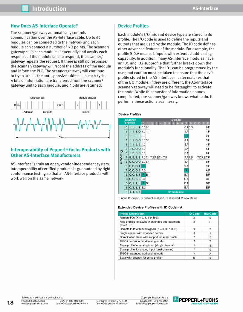
How Does AS-Interface Operate?The scanner/gateway automatically controls communication over the AS-Interface cable. Up to 62 modules can be connected to the network and each module can connect a number of I/O points. The scanner/gateway calls each module sequentially and awaits each response. If the module fails to respond, the scanner/gateway repeats the request. If there is still no response, the scanner/gateway will record the address of the module and inform the PLC. The scanner/gateway will continue to try to access the unresponsive address. In each cycle, 4 bits of information are transferred from the scanner/gateway unit to each module, and 4 bits are returned.
Interoperability of Pepperl+Fuchs Products with Other AS-Interface Manufacturers
AS-Interface is truly an open, vendor-independent system. Interoperability of certified products is guaranteed by rigid conformance testing so that all AS-Interface products will work well on the same network.
0 I, I, I, I1 I, I, I, O2 I, I, I, B3 I, I, O, O4 I, I, B, B5 I, O, O, O6 I, B, B, B7 B, B, B, B8 O, O, O, O9 O, O, O, IA O, O, O, BB O, O, I, IC O, O, B, BD O, I, I, I E O, B, B, BF T, T, T, T
Scannerprofiles
ID code
for future use
I: input, O: output, B: bidirectional port, R: reserved, V: new status
00.0 0.1 0.A
1.AR
3.A4.A5.A6.A7.A 7.B 7.D 7.E8.A9.AR
B.AC.AD.AE.A
1.F2.F3.F4.F5.F6.F7.F8.F9.FA.FB.FC.FD.FE.F
0.B 0.F1.02.03.04.05.06.07.0 7.1 7.2 7.3 7.4 7.58.0 8.1R
A.0R B.1
D.1C.0R
E.0
3.1
1.1
1 2 3 4 5 6 7 8 9 A B C D E F
IOCODE
Device Profiles
153 ms
Scanner call
– Address– Outputs Inputs
0 SB PB 1 10
Module answer
Extended Device Profiles with ID Code = A
Profile Description IO Code ID2 CodeRemote I/Os (X = 0, 1, 3-9, B-E) X 0Free profiles for slaves in extended address mode (X = 0 ... E)
X E
Remote I/Os with dual signals (X = 0, 3, 7, 8, B) X 2Single sensor with extended control 3 1Combination slave with support for serial profile 7 54I/4O in extended addressing mode 7 7Slave profile for analog input (single channel) 7 8Slave profile for analog input (dual channel) 7 98I/8O in extended addressing mode 7 ASlave with support for serial profile B 5
Device Profiles
Each module’s I/O mix and device type are stored in its profile. The I/O code is used to define the inputs and outputs that are used by the module. The ID code defines other advanced features of the module. For example, the profile S-0.A means 4 inputs with extended addressing capability. In addition, many AS-Interface modules have an ID1 and ID2 subprofile that further breaks down the module’s functionality. The ID1 can be programmed by the user, but caution must be taken to ensure that the device profile stored in the AS-Interface master matches that of the I/O module. If they are different, the AS-Interface scanner/gateway will need to be “retaught” to activate the node. While this transfer of information sounds complicated, the scanner/gateway knows what to do. It performs these actions seamlessly.
19Singapore: +65 6779 [email protected]
USA: +1 330 486 [email protected]
Germany: +49 621 [email protected]
Pepperl+Fuchs Groupwww.pepperl-fuchs.com
Subject to modifications without notice Copyright Pepperl+Fuchs
Introduction AS-Interface
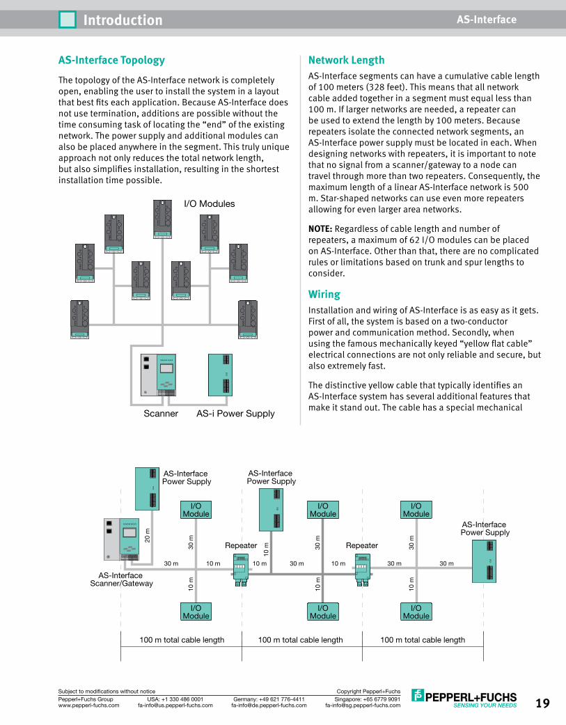
AS-Interface Topology
The topology of the AS-Interface network is completely open, enabling the user to install the system in a layout that best fits each application. Because AS-Interface does not use termination, additions are possible without the time consuming task of locating the “end” of the existing network. The power supply and additional modules can also be placed anywhere in the segment. This truly unique approach not only reduces the total network length, but also simplifies installation, resulting in the shortest installation time possible.
Scanner
I/O Modules
AS-i Power Supply
Network LengthAS-Interface segments can have a cumulative cable length of 100 meters (328 feet). This means that all network cable added together in a segment must equal less than 100 m. If larger networks are needed, a repeater can be used to extend the length by 100 meters. Because repeaters isolate the connected network segments, an AS-Interface power supply must be located in each. When designing networks with repeaters, it is important to note that no signal from a scanner/gateway to a node can travel through more than two repeaters. Consequently, the maximum length of a linear AS-Interface network is 500 m. Star-shaped networks can use even more repeaters allowing for even larger area networks.
NOTE: Regardless of cable length and number of repeaters, a maximum of 62 I/O modules can be placed on AS-Interface. Other than that, there are no complicated rules or limitations based on trunk and spur lengths to consider.
WiringInstallation and wiring of AS-Interface is as easy as it gets. First of all, the system is based on a two-conductor power and communication method. Secondly, when using the famous mechanically keyed “yellow flat cable” electrical connections are not only reliable and secure, but also extremely fast.
The distinctive yellow cable that typically identifies an AS-Interface system has several additional features that make it stand out. The cable has a special mechanical
I/OModule
I/OModule
I/OModule
I/OModule
I/OModule
I/OModule
Repeater Repeater
AS-Interface Power Supply
AS-Interface Scanner/Gateway
AS-Interface Power Supply
AS-Interface Power Supply
100 m total cable length
30 m 10 m 10 m 30 m 10 m 30 m 30 m
20 m
30 m
30 m
30 m
10 m
10 m
10 m
10 m
100 m total cable length 100 m total cable length
20 Singapore: +65 6779 [email protected]
USA: +1 330 486 [email protected]
Germany: +49 621 [email protected]
Pepperl+Fuchs Groupwww.pepperl-fuchs.com
Subject to modifications without notice Copyright Pepperl+Fuchs
Introduction AS-Interface
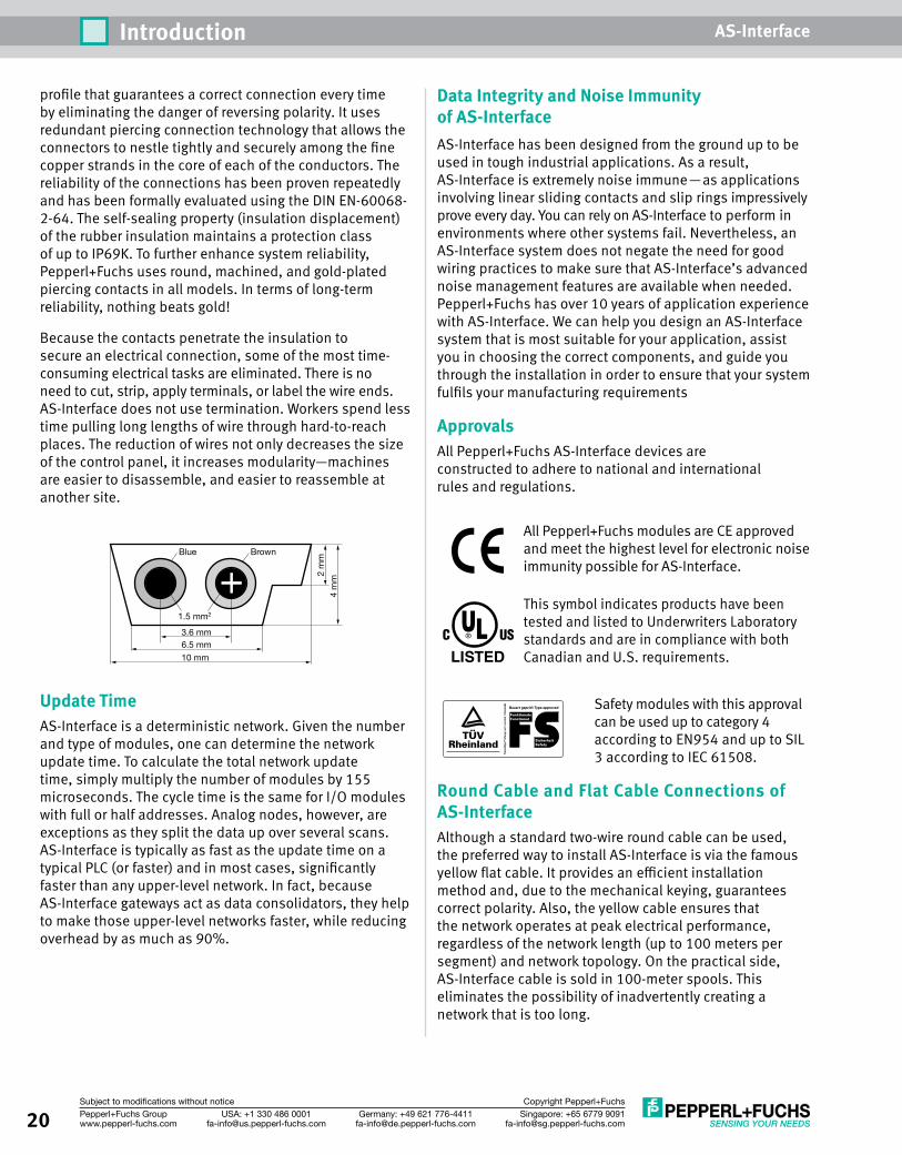
profile that guarantees a correct connection every time by eliminating the danger of reversing polarity. It uses redundant piercing connection technology that allows the connectors to nestle tightly and securely among the fine copper strands in the core of each of the conductors. The reliability of the connections has been proven repeatedly and has been formally evaluated using the DIN EN-60068-2-64. The self-sealing property (insulation displacement) of the rubber insulation maintains a protection class of up to IP69K. To further enhance system reliability, Pepperl+Fuchs uses round, machined, and gold-plated piercing contacts in all models. In terms of long-term reliability, nothing beats gold!
Because the contacts penetrate the insulation to secure an electrical connection, some of the most time-consuming electrical tasks are eliminated. There is no need to cut, strip, apply terminals, or label the wire ends. AS-Interface does not use termination. Workers spend less time pulling long lengths of wire through hard-to-reach places. The reduction of wires not only decreases the size of the control panel, it increases modularity—machines are easier to disassemble, and easier to reassemble at another site.
Update TimeAS-Interface is a deterministic network. Given the number and type of modules, one can determine the network update time. To calculate the total network update time, simply multiply the number of modules by 155 microseconds. The cycle time is the same for I/O modules with full or half addresses. Analog nodes, however, are exceptions as they split the data up over several scans. AS-Interface is typically as fast as the update time on a typical PLC (or faster) and in most cases, significantly faster than any upper-level network. In fact, because AS-Interface gateways act as data consolidators, they help to make those upper-level networks faster, while reducing overhead by as much as 90%.
Data Integrity and Noise Immunity of AS-InterfaceAS-Interface has been designed from the ground up to be used in tough industrial applications. As a result, AS-Interface is extremely noise immune—as applications involving linear sliding contacts and slip rings impressively prove every day. You can rely on AS-Interface to perform in environments where other systems fail. Nevertheless, an AS-Interface system does not negate the need for good wiring practices to make sure that AS-Interface’s advanced noise management features are available when needed. Pepperl+Fuchs has over 10 years of application experience with AS-Interface. We can help you design an AS-Interface system that is most suitable for your application, assist you in choosing the correct components, and guide you through the installation in order to ensure that your system fulfils your manufacturing requirements
ApprovalsAll Pepperl+Fuchs AS-Interface devices are constructed to adhere to national and international rules and regulations.
All Pepperl+Fuchs modules are CE approved and meet the highest level for electronic noise immunity possible for AS-Interface.
This symbol indicates products have been tested and listed to Underwriters Laboratory standards and are in compliance with both Canadian and U.S. requirements.
Safety modules with this approval can be used up to category 4 according to EN954 and up to SIL 3 according to IEC 61508.
Round Cable and Flat Cable Connections of AS-Interface Although a standard two-wire round cable can be used, the preferred way to install AS-Interface is via the famous yellow flat cable. It provides an efficient installation method and, due to the mechanical keying, guarantees correct polarity. Also, the yellow cable ensures that the network operates at peak electrical performance, regardless of the network length (up to 100 meters per segment) and network topology. On the practical side, AS-Interface cable is sold in 100-meter spools. This eliminates the possibility of inadvertently creating a network that is too long.
Blue
1.5 mm2
3.6 mm6.5 mm
2 m
m4
mm
10 mm
Brown
LISTED
21Singapore: +65 6779 [email protected]
USA: +1 330 486 [email protected]
Germany: +49 621 [email protected]
Pepperl+Fuchs Groupwww.pepperl-fuchs.com
Subject to modifications without notice Copyright Pepperl+Fuchs
Introduction AS-Interface
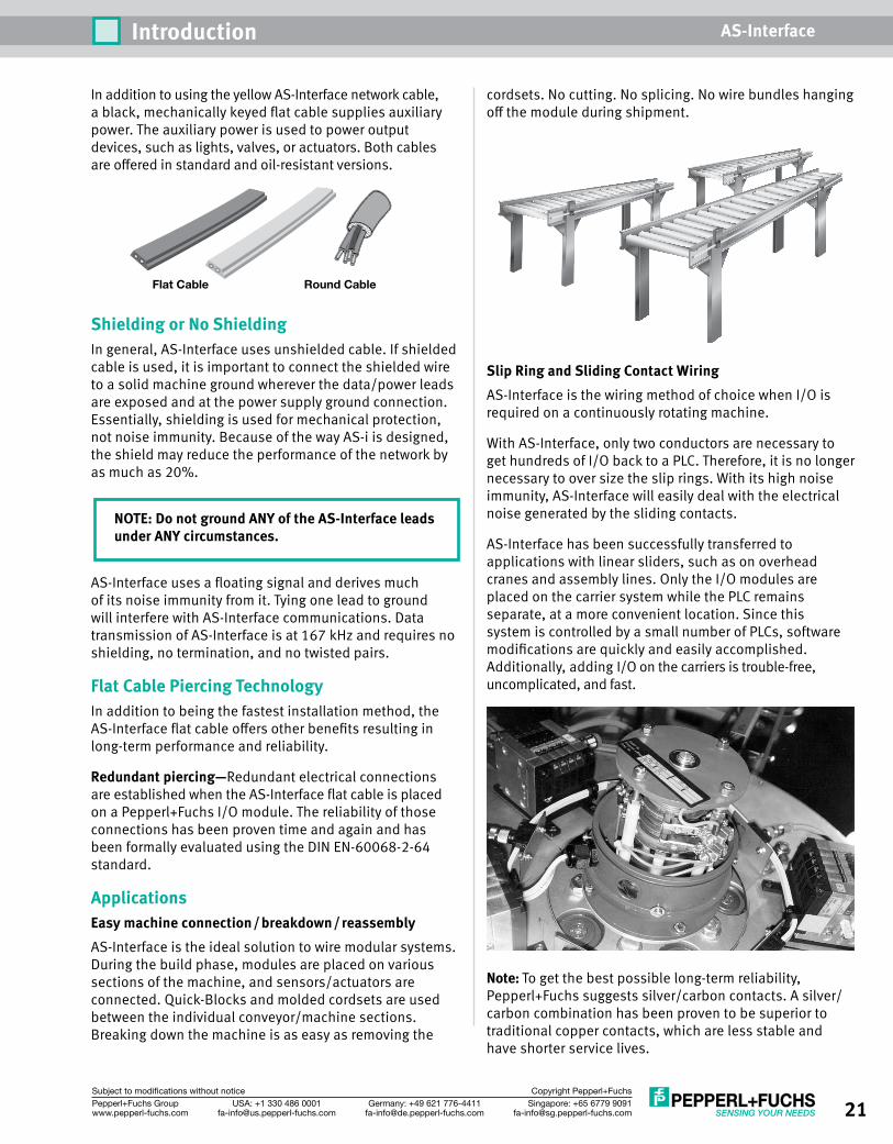
In addition to using the yellow AS-Interface network cable, a black, mechanically keyed flat cable supplies auxiliary power. The auxiliary power is used to power output devices, such as lights, valves, or actuators. Both cables are offered in standard and oil-resistant versions.
Shielding or No ShieldingIn general, AS-Interface uses unshielded cable. If shielded cable is used, it is important to connect the shielded wire to a solid machine ground wherever the data/power leads are exposed and at the power supply ground connection. Essentially, shielding is used for mechanical protection, not noise immunity. Because of the way AS-i is designed, the shield may reduce the performance of the network by as much as 20%.
NOTE: Do not ground ANY of the AS-Interface leads under ANY circumstances.
AS-Interface uses a floating signal and derives much of its noise immunity from it. Tying one lead to ground will interfere with AS-Interface communications. Data transmission of AS-Interface is at 167 kHz and requires no shielding, no termination, and no twisted pairs.
Flat Cable Piercing TechnologyIn addition to being the fastest installation method, the AS-Interface flat cable offers other benefits resulting in long-term performance and reliability.
Redundant piercing—Redundant electrical connections are established when the AS-Interface flat cable is placed on a Pepperl+Fuchs I/O module. The reliability of those connections has been proven time and again and has been formally evaluated using the DIN EN-60068-2-64 standard.
ApplicationsEasy machine connection/breakdown/reassemblyAS-Interface is the ideal solution to wire modular systems. During the build phase, modules are placed on various sections of the machine, and sensors/actuators are connected. Quick-Blocks and molded cordsets are used between the individual conveyor/machine sections. Breaking down the machine is as easy as removing the
cordsets. No cutting. No splicing. No wire bundles hanging off the module during shipment.
Slip Ring and Sliding Contact WiringAS-Interface is the wiring method of choice when I/O is required on a continuously rotating machine.
With AS-Interface, only two conductors are necessary to get hundreds of I/O back to a PLC. Therefore, it is no longer necessary to over size the slip rings. With its high noise immunity, AS-Interface will easily deal with the electrical noise generated by the sliding contacts.
AS-Interface has been successfully transferred to applications with linear sliders, such as on overhead cranes and assembly lines. Only the I/O modules are placed on the carrier system while the PLC remains separate, at a more convenient location. Since this system is controlled by a small number of PLCs, software modifications are quickly and easily accomplished. Additionally, adding I/O on the carriers is trouble-free, uncomplicated, and fast.
Note: To get the best possible long-term reliability, Pepperl+Fuchs suggests silver/carbon contacts. A silver/carbon combination has been proven to be superior to traditional copper contacts, which are less stable and have shorter service lives.
Flat Cable Round Cable
22 Singapore: +65 6779 [email protected]
USA: +1 330 486 [email protected]
Germany: +49 621 [email protected]
Pepperl+Fuchs Groupwww.pepperl-fuchs.com
Subject to modifications without notice Copyright Pepperl+Fuchs
Introduction AS-Interface
Safety
It is also possible to route safety data (from door interlocks, e-stops, light curtains) over AS-Interface. AS-Interface Safety at Work allows networking of safety devices using a standard AS-Interface network. With the Safety at Work system, safety devices benefit from all of the advantages that AS-Interface offers. Safety input status is directly available to the PLC without the need for additional wiring to auxiliary contacts. The safe outputs on the SafetyMonitor (roughly equivalent to the safety relay in a hardwired system) can also be retrieved by the PLC without the need for additional wiring.
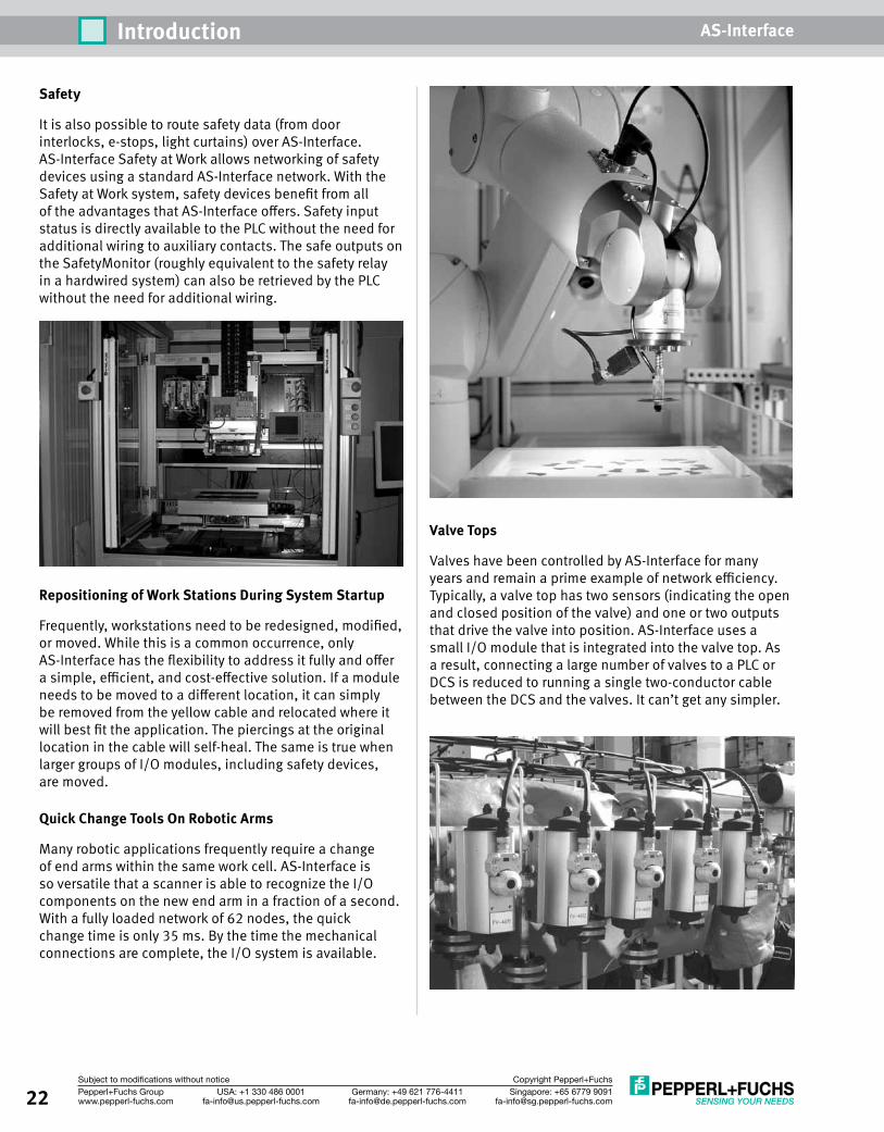
Repositioning of Work Stations During System Startup
Frequently, workstations need to be redesigned, modified, or moved. While this is a common occurrence, only AS-Interface has the flexibility to address it fully and offer a simple, efficient, and cost-effective solution. If a module needs to be moved to a different location, it can simply be removed from the yellow cable and relocated where it will best fit the application. The piercings at the original location in the cable will self-heal. The same is true when larger groups of I/O modules, including safety devices, are moved.
Quick Change Tools On Robotic Arms
Many robotic applications frequently require a change of end arms within the same work cell. AS-Interface is so versatile that a scanner is able to recognize the I/O components on the new end arm in a fraction of a second. With a fully loaded network of 62 nodes, the quick change time is only 35 ms. By the time the mechanical connections are complete, the I/O system is available.
Valve Tops
Valves have been controlled by AS-Interface for many years and remain a prime example of network efficiency. Typically, a valve top has two sensors (indicating the open and closed position of the valve) and one or two outputs that drive the valve into position. AS-Interface uses a small I/O module that is integrated into the valve top. As a result, connecting a large number of valves to a PLC or DCS is reduced to running a single two-conductor cable between the DCS and the valves. It can’t get any simpler.
23Singapore: +65 6779 [email protected]
USA: +1 330 486 [email protected]
Germany: +49 621 [email protected]
Pepperl+Fuchs Groupwww.pepperl-fuchs.com
Subject to modifications without notice Copyright Pepperl+Fuchs
Introduction AS-Interface
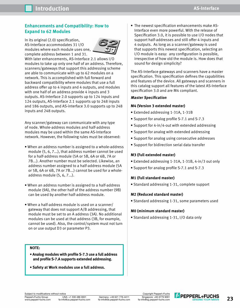
Enhancements and Compatibility: How to Expand to 62 Modules
In its original (2.0) specification, AS-Interface accommodates 31 I/O modules where each module uses one, complete address between 1 and 31. With later enhancements, AS-Interface 2.1 allows I/O modules to take up only one half of an address. Therefore, scanners/gateways that support this addressing scheme are able to communicate with up to 62 modules on a network. This is accomplished with full forward and backward compatibility where modules that use a full address offer up to 4 inputs and 4 outputs, and modules with one half of an address provide 4 inputs and 3 outputs. AS-Interface 2.0 supports up to 124 inputs and 124 outputs, AS-Interface 2.1 supports up to 248 inputs and 186 outputs, and AS-interface 3.0 supports up to 248 inputs and 248 outputs.
Any scanner/gateway can communicate with any type of node. Whole-address modules and half-address modules may be used within the same AS-Interface network. However, the following rules must be observed:
• When an address number is assigned to a whole-address module (5, 6, 7...), that address number cannot be used for a half-address module (5A or 5B, 6A or 6B, 7A or 7B...). Another number must be selected. Likewise, an address number assigned to a half-address module (5A or 5B, 6A or 6B, 7A or 7B...) cannot be used for a whole-address module (5, 6, 7...).
• When an address number is assigned to a half-address module (9A), the other half of the address number (9B) can be used by another half-address module.
• When a half-address module is used on a scanner/gateway that does not support A/B addressing, that module must be set to an A address (3A). No additional modules can be used at that address (3B, for example, cannot be used). Also, the control/system must not turn on or use output D3 or parameter P3.
NOTE: • Analog modules with profile S-7.3 use a full address
and profile S-7.A supports extended addressing.
• Safety at Work modules use a full address.
• The newest specification enhancements make AS-Interface even more powerful. With the release of Specification 3.0, it is possible to use I/O nodes that support half-addresses and still offer 4 inputs and 4 outputs. As long as a scanner/gateway is used that supports this newest specification, selecting an I/O module is easy: any configuration is possible, irrespective of how old the module is. How does that sound for design simplicity?
The AS-Interface gateways and scanners have a master specification. This specification defines the capabilities and features of the device. All gateways and scanners in this catalog support all features of the latest AS-Interface specification 3.0 and are M4 compliant.
Master Specification
M4 (Version 3 extended master)• Extended addressing 1-31A, 1-31B• Support for analog profile S-7.1 and S-7.3• Support for 4-in/4-out with extended addressing• Support for analog with extended addressing• Support for analog using consecutive addresses• Support for bidirection serial data transfer
M3 (Full extended master)• Extended addressing 1-31A, 1-31B, 4-in/3 out only• Support for analog profile S-7.1 and S-7.3
M1 (Full standard master)• Standard addressing 1-31, complete support
M2 (Reduced standard master)• Standard addressing 1-31, some parameters used
M0 (minimum standard master)• Standard addressing 1-31, I/O data only
24 Singapore: +65 6779 [email protected]
USA: +1 330 486 [email protected]
Germany: +49 621 [email protected]
Pepperl+Fuchs Groupwww.pepperl-fuchs.com
Subject to modifications without notice Copyright Pepperl+Fuchs
Introduction AS-Interface
AS-i Power Supply
24 VDCPower Supply
I/O Module Output Module
Splitter
Splitter
InputModule
Input Module
AS-i Gateway
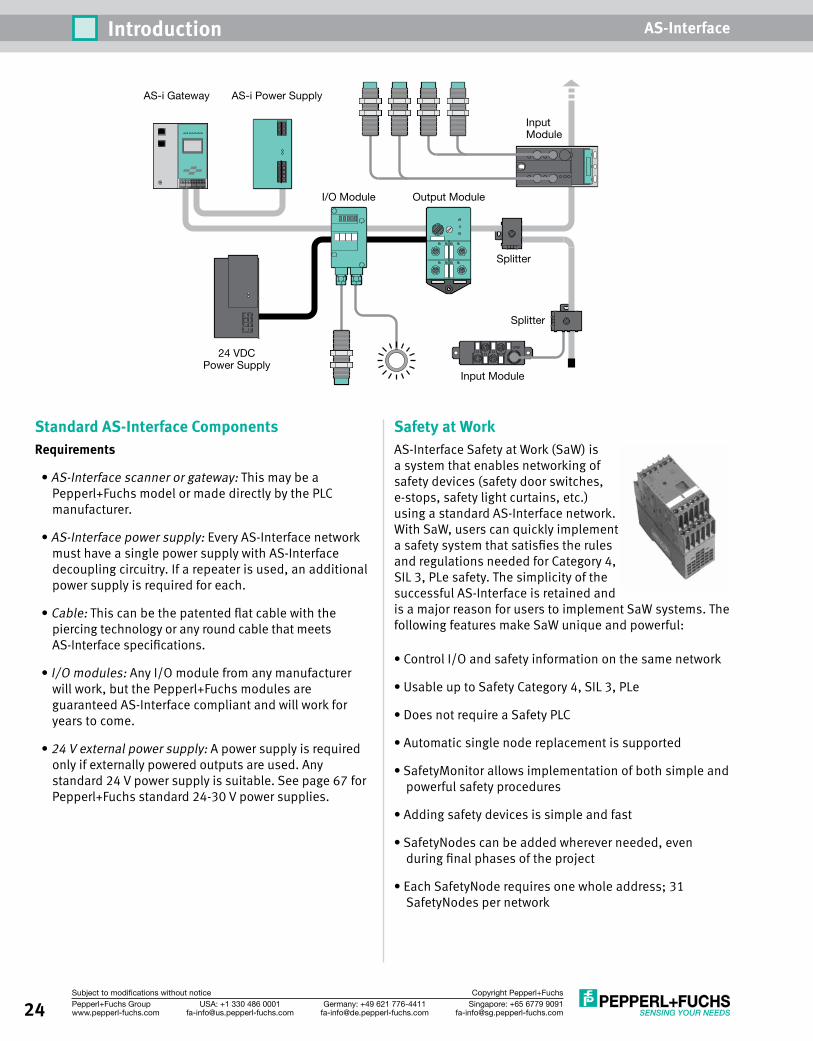
Standard AS-Interface ComponentsRequirements
• AS-Interface scanner or gateway: This may be a Pepperl+Fuchs model or made directly by the PLC manufacturer.
• AS-Interface power supply: Every AS-Interface network must have a single power supply with AS-Interface decoupling circuitry. If a repeater is used, an additional power supply is required for each.
• Cable: This can be the patented flat cable with the piercing technology or any round cable that meets AS-Interface specifications.
• I/O modules: Any I/O module from any manufacturer will work, but the Pepperl+Fuchs modules are guaranteed AS-Interface compliant and will work for years to come.
• 24 V external power supply: A power supply is required only if externally powered outputs are used. Any standard 24 V power supply is suitable. See page 67 for Pepperl+Fuchs standard 24-30 V power supplies.
Safety at Work AS-Interface Safety at Work (SaW) is a system that enables networking of safety devices (safety door switches, e-stops, safety light curtains, etc.) using a standard AS-Interface network. With SaW, users can quickly implement a safety system that satisfies the rules and regulations needed for Category 4, SIL 3, PLe safety. The simplicity of the successful AS-Interface is retained and is a major reason for users to implement SaW systems. The following features make SaW unique and powerful:
• Control I/O and safety information on the same network
• Usable up to Safety Category 4, SIL 3, PLe
• Does not require a Safety PLC
• Automatic single node replacement is supported
• SafetyMonitor allows implementation of both simple and powerful safety procedures
• Adding safety devices is simple and fast
• SafetyNodes can be added wherever needed, even during final phases of the project
• Each SafetyNode requires one whole address; 31 SafetyNodes per network
25Singapore: +65 6779 [email protected]
USA: +1 330 486 [email protected]
Germany: +49 621 [email protected]
Pepperl+Fuchs Groupwww.pepperl-fuchs.com
Subject to modifications without notice Copyright Pepperl+Fuchs
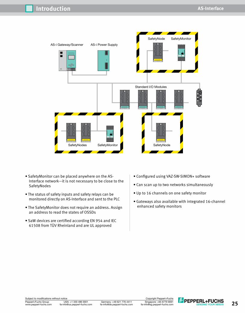
Introduction AS-Interface
• SafetyMonitor can be placed anywhere on the AS-Interface network—it is not necessary to be close to the SafetyNodes
• The status of safety inputs and safety relays can be monitored directly on AS-Interface and sent to the PLC
• The SafetyMonitor does not require an address. Assign an address to read the states of OSSDs
• SaW devices are certified according EN 954 and IEC 61508 from TÜV Rheinland and are UL approved
• Configured using VAZ-SW-SIMON+ software
• Can scan up to two networks simultaneously
• Up to 16 channels on one safety monitor
• Gateways also available with integrated 16-channel enhanced safety monitors
AS-i Power SupplyAS-i Gateway/Scanner
SafetyNode SafetyMonitor
SafetyNodes SafetyMonitor SafetyNode
Standard I/O Modules

26 Singapore: +65 6779 [email protected]
USA: +1 330 486 [email protected]
Germany: +49 621 [email protected]
Pepperl+Fuchs Groupwww.pepperl-fuchs.com
Subject to modifications without notice Copyright Pepperl+Fuchs
Introduction AS-Interface
Notes
27Singapore: +65 6779 [email protected]
USA: +1 330 486 [email protected]
Germany: +49 621 [email protected]
Pepperl+Fuchs Groupwww.pepperl-fuchs.com
Subject to modifications without notice Copyright Pepperl+Fuchs
Gat
eway
s an
d Sc
anne
rsPo
wer
Sup
plie
s an
d Re
peat
ers
I/O M
odul
esSa
fety
at W
ork
Sens
ors
Cord
sets
Acce
ssor
ies
Singapore: +65 6779 [email protected]
USA: +1 330 486 [email protected]
Germany: +49 621 [email protected]
Pepperl+Fuchs Groupwww.pepperl-fuchs.com
Subject to modifications without notice Copyright Pepperl+Fuchs
Gateways and Scanners
Gateways and
Scanners
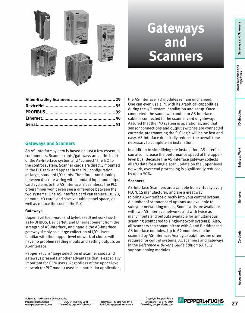
Gateways and Scanners An AS-Interface system is based on just a few essential components. Scanner cards/gateways are at the heart of the AS-Interface system and “connect” the I/O to the control system. Scanner cards are directly mounted in the PLC rack and appear in the PLC configuration as large, standard I/O cards. Therefore, transitioning between discrete wiring with standard input and output card systems to the AS-Interface is seamless. The PLC programmer won’t even see a difference between the two systems. One AS-Interface card can replace 10, 20, or more I/O cards and save valuable panel space, as well as reduce the cost of the PLC.
GatewaysUpper-level (i.e., word- and byte-based) networks such as PROFIBUS, DeviceNet, and Ethernet benefit from the strength of AS-Interface, and handle the AS-Interface gateway simply as a large collection of I/O. Users familiar with their upper-level network of choice will have no problem reading inputs and setting outputs on AS-Interface.
Pepperl+Fuchs’ large selection of scanner cards and gateways presents another advantage that is especially important for OEM users. Regardless of the upper-level network (or PLC model) used in a particular application,
the AS-Interface I/O modules remain unchanged. One can even use a PC with its graphical capabilities during the I/O system installation and setup. Once completed, the same two-conductor AS-Interface cable is connected to the scanner card or gateway. Assured that the I/O system is operational, and that sensor connections and output switches are connected correctly, programming the PLC logic will be be fast and easy. AS-Interface drastically reduces the overall time necessary to complete an installation.
In addition to simplifying the installation, AS-Interface can also increase the performance speed of the upper-level bus. Because the AS-Interface gateway collects all I/O data for a single scan update on the upper-level network, overhead processing is significantly reduced, by up to 90%.
ScannersAS-Interface Scanners are available from virtually every PLC/DCS manufacturer, and are a great way to bring AS-Interface directly into your control system. A number of scanner card options are available to suit your networking needs. Some cards are available with two AS-Interface networks and with twice as many inputs and outputs available for simultaneous scanning (compared to single-network systems). Also, all scanners can communicate with A and B addressed AS-Interface modules. Up to 62 modules can be scanned by AS-Interface. Analog capabilities are often required for control systems. All scanners and gateways in the Reference & Buyer’s Guide Edition 6.0 fully support analog modules.
Allen-Bradley Scanners ...................................29DeviceNet .......................................................35PROFIBUS .......................................................39Ethernet..........................................................46Serial ..............................................................51
28 Singapore: +65 6779 [email protected]
USA: +1 330 486 [email protected]
Germany: +49 621 [email protected]
Pepperl+Fuchs Groupwww.pepperl-fuchs.com
Subject to modifications without notice Copyright Pepperl+Fuchs
Gateways and Scanners AS-InterfaceG
atew
ays
and
Scan
ners
Pow
er S
uppl
ies
and
Repe
ater
sI/O
Mod
ules
Safe
ty a
t Wor
kSe
nsor
sCo
rdse
tsAccessories
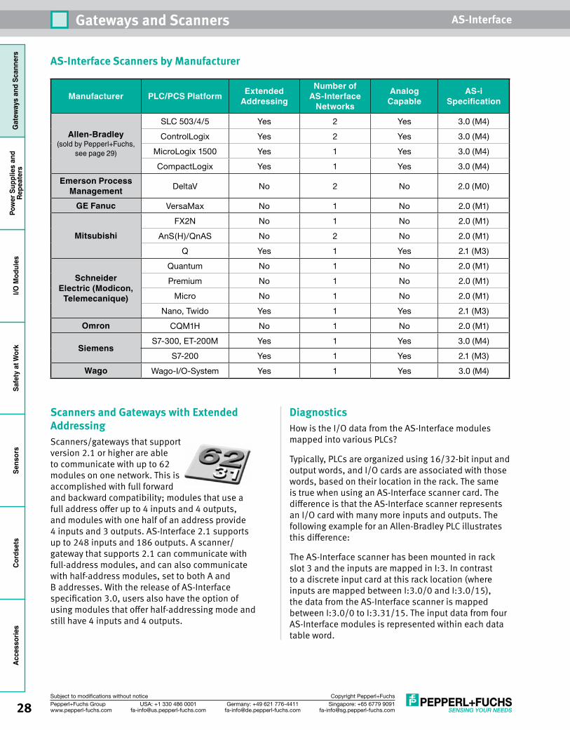
Scanners and Gateways with Extended AddressingScanners/gateways that support version 2.1 or higher are able to communicate with up to 62 modules on one network. This is accomplished with full forward and backward compatibility; modules that use a full address offer up to 4 inputs and 4 outputs, and modules with one half of an address provide 4 inputs and 3 outputs. AS-Interface 2.1 supports up to 248 inputs and 186 outputs. A scanner/gateway that supports 2.1 can communicate with full-address modules, and can also communicate with half-address modules, set to both A and B addresses. With the release of AS-Interface specification 3.0, users also have the option of using modules that offer half-addressing mode and still have 4 inputs and 4 outputs.
AS-Interface Scanners by Manufacturer
DiagnosticsHow is the I/O data from the AS-Interface modules mapped into various PLCs?
Typically, PLCs are organized using 16/32-bit input and output words, and I/O cards are associated with those words, based on their location in the rack. The same is true when using an AS-Interface scanner card. The difference is that the AS-Interface scanner represents an I/O card with many more inputs and outputs. The following example for an Allen-Bradley PLC illustrates this difference:
The AS-Interface scanner has been mounted in rack slot 3 and the inputs are mapped in I:3. In contrast to a discrete input card at this rack location (where inputs are mapped between I:3.0/0 and I:3.0/15), the data from the AS-Interface scanner is mapped between I:3.0/0 to I:3.31/15. The input data from four AS-Interface modules is represented within each data table word.
Manufacturer PLC/PCS Platform Extended Addressing
Number of AS-Interface
Networks
Analog Capable
AS-i Specification
Allen-Bradley(sold by Pepperl+Fuchs,
see page 29)
SLC 503/4/5 Yes 2 Yes 3.0 (M4)
ControlLogix Yes 2 Yes 3.0 (M4)
MicroLogix 1500 Yes 1 Yes 3.0 (M4)
CompactLogix Yes 1 Yes 3.0 (M4)
Emerson Process Management DeltaV No 2 No 2.0 (M0)
GE Fanuc VersaMax No 1 No 2.0 (M1)
MitsubishiFX2N No 1 No 2.0 (M1)
AnS(H)/QnAS No 2 No 2.0 (M1)
Q Yes 1 Yes 2.1 (M3)
Schneider Electric (Modicon,
Telemecanique)
Quantum No 1 No 2.0 (M1)
Premium No 1 No 2.0 (M1)
Micro No 1 No 2.0 (M1)
Nano, Twido Yes 1 Yes 2.1 (M3)
Omron CQM1H No 1 No 2.0 (M1)
SiemensS7-300, ET-200M Yes 1 Yes 3.0 (M4)
S7-200 Yes 1 Yes 2.1 (M3)
Wago Wago-I/O-System Yes 1 Yes 3.0 (M4)
29Singapore: +65 6779 [email protected]
USA: +1 330 486 [email protected]
Germany: +49 621 [email protected]
Pepperl+Fuchs Groupwww.pepperl-fuchs.com
Subject to modifications without notice Copyright Pepperl+Fuchs
Gateways and Scanners AS-Interface
Gat
eway
s an
d Sc
anne
rsPo
wer
Sup
plie
s an
d Re
peat
ers
I/O M
odul
esSa
fety
at W
ork
Sens
ors
Cord
sets
Acce
ssor
ies
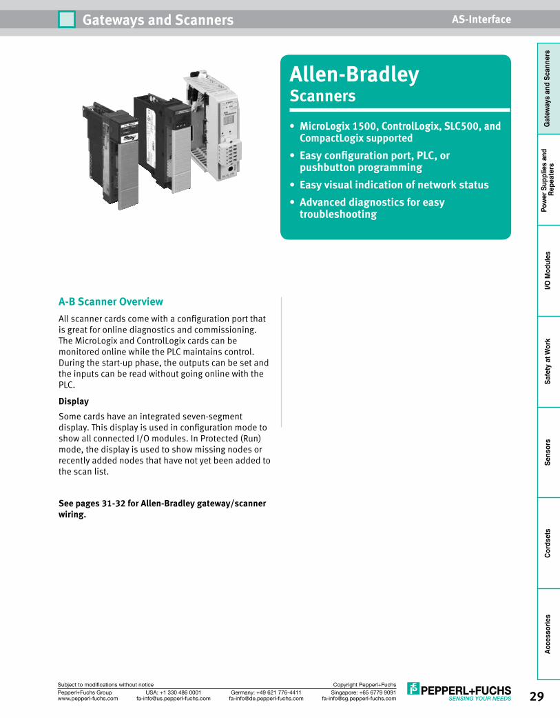
Allen-BradleyScanners• MicroLogix1500,ControlLogix,SLC500,andCompactLogixsupported
• Easyconfigurationport,PLC,orpushbuttonprogramming
• Easyvisualindicationofnetworkstatus• Advanceddiagnosticsforeasy
troubleshooting
A-B Scanner OverviewAll scanner cards come with a configuration port that is great for online diagnostics and commissioning. The MicroLogix and ControlLogix cards can be monitored online while the PLC maintains control. During the start-up phase, the outputs can be set and the inputs can be read without going online with the PLC.
DisplaySome cards have an integrated seven-segment display. This display is used in configuration mode to show all connected I/O modules. In Protected (Run) mode, the display is used to show missing nodes or recently added nodes that have not yet been added to the scan list.
Seepages31-32forAllen-Bradleygateway/scannerwiring.
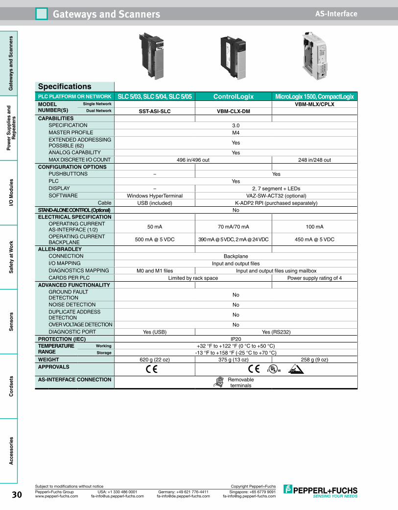
30 Singapore: +65 6779 [email protected]
USA: +1 330 486 [email protected]
Germany: +49 621 [email protected]
Pepperl+Fuchs Groupwww.pepperl-fuchs.com
Subject to modifications without notice Copyright Pepperl+Fuchs
Gateways and Scanners AS-InterfaceG
atew
ays
and
Scan
ners
Pow
er S
uppl
ies
and
Repe
ater
sI/O
Mod
ules
Safe
ty a
t Wor
kSe
nsor
sCo
rdse
tsAccessories
SpecificationsPLC PLATFORM OR NETWORK SLC 5/03, SLC 5/04, SLC 5/05 ControlLogix MicroLogix 1500, CompactLogixMODEL NUMBER(S)
Single Network VBM-MLX/CPLXDual Network SST-ASI-SLC VBM-CLX-DM
CAPABILITIESSPECIFICATION 3.0MASTER PROFILE M4 EXTENDED ADDRESSING POSSIBLE (62) Yes
ANALOG CAPABILITY YesMAX DISCRETE I/O COUNT 496 in/496 out 248 in/248 out
CONFIGURATION OPTIONSPUSHBUTTONS – Yes PLC Yes DISPLAY – 2, 7 segment + LEDs SOFTWARE Windows HyperTerminal VAZ-SW-ACT32 (optional)
Cable USB (included) K-ADP2 RPI (purchased separately)STAND-ALONE CONTROL (Optional) NoELECTRICAL SPECIFICATION
OPERATING CURRENT AS-INTERFACE (1/2) 50 mA 70 mA/70 mA 100 mA
OPERATING CURRENT BACKPLANE 500 mA @ 5 VDC 390 mA @ 5 VDC, 2 mA @ 24 VDC 450 mA @ 5 VDC
ALLEN-BRADLEYCONNECTION BackplaneI/O MAPPING Input and output files DIAGNOSTICS MAPPING M0 and M1 files Input and output files using mailbox CARDS PER PLC Limited by rack space Power supply rating of 4
ADVANCED FUNCTIONALITYGROUND FAULT DETECTION No
NOISE DETECTION NoDUPLICATE ADDRESS DETECTION No
OVER VOLTAGE DETECTION NoDIAGNOSTIC PORT Yes (USB) Yes (RS232)
PROTECTION (IEC) IP20TEMPERATURE RANGE
Working +32 °F to +122 °F (0 °C to +50 °C)Storage -13 °F to +158 °F (-25 °C to +70 °C)
WEIGHT 620 g (22 oz) 375 g (13 oz) 258 g (9 oz)APPROVALS
AS-INTERFACE CONNECTION Removable terminals
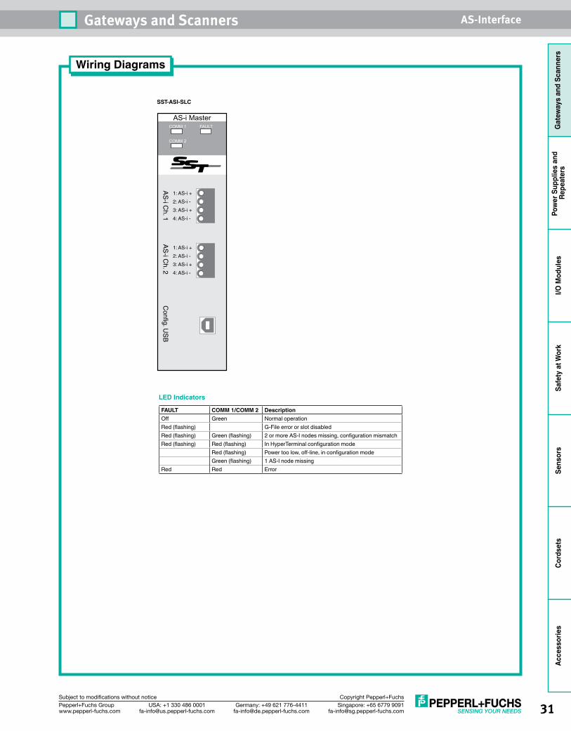
31Singapore: +65 6779 [email protected]
USA: +1 330 486 [email protected]
Germany: +49 621 [email protected]
Pepperl+Fuchs Groupwww.pepperl-fuchs.com
Subject to modifications without notice Copyright Pepperl+Fuchs
Gateways and Scanners AS-Interface
Gat
eway
s an
d Sc
anne
rsPo
wer
Sup
plie
s an
d Re
peat
ers
I/O M
odul
esSa
fety
at W
ork
Sens
ors
Cord
sets
Acce
ssor
ies
SST-ASI-SLC
Config. U
SB
AS
-i Ch. 1
1: AS-i +
2: AS-i -
3: AS-i +
4: AS-i -
1: AS-i +
2: AS-i -
3: AS-i +
4: AS-i -
AS
-i Ch. 2
Wiring Diagrams
LED Indicators
FAULT COMM 1/COMM 2 DescriptionOff Green Normal operationRed (flashing) G-File error or slot disabledRed (flashing) Green (flashing) 2 or more AS-I nodes missing, configuration mismatchRed (flashing) Red (flashing) In HyperTerminal configuration mode
Red (flashing) Power too low, off-line, in configuration modeGreen (flashing) 1 AS-I node missing
Red Red Error
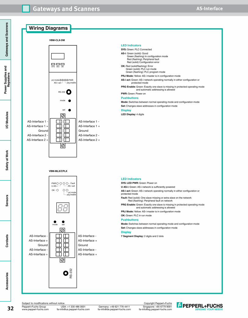
32 Singapore: +65 6779 [email protected]
USA: +1 330 486 [email protected]
Germany: +49 621 [email protected]
Pepperl+Fuchs Groupwww.pepperl-fuchs.com
Subject to modifications without notice Copyright Pepperl+Fuchs
Gateways and Scanners AS-InterfaceG
atew
ays
and
Scan
ners
Pow
er S
uppl
ies
and
Repe
ater
sI/O
Mod
ules
Safe
ty a
t Wor
kSe
nsor
sCo
rdse
tsAccessories
VBM-CLX-DM
VBM-MLX/CPLX
set
mode
RS-232
prj modeprg enable
PWR
SYS AS-i OK
AS-i act
AS-Interface 1 -
AS-Interface 1 +
AS-Interface 2 -
AS-Interface 2 +
Ground
AS-Interface 1 -
AS-Interface 1 +
AS-Interface 2 -
AS-Interface 2 +
Ground
Fault
setmode
prj modeprg enable
PWR
OK
AS-i act
AS-Interface -
AS-Interface +
AS-Interface -
AS-Interface +
RS
-232
Ground
AS-Interface -
AS-Interface +
AS-Interface -
AS-Interface +
Ground
U AS-i
Wiring Diagrams
LED IndicatorsSYS: Green: PLC ConnectedAS-i: Green (solid): Good
Green (flashing) In configuration mode Red (flashing): Peripheral fault Red (solid) Configuration error
OK: Red (solid/flashing): Error Green (solid): PLC run mode Green (flashing): PLC program mode
PRJ Mode: Yellow: AS-i master is in configuration modeAS-i act: Green: AS-i network operating normally in either configuration or
protected modePRG Enable: Green: Exactly one slave is missing in protected operating mode
and automatic addressing is allowedPWR: Green: Power on
PushbuttonsMode: Switches between normal operating mode and configuration modeSet: Changes slave addresses in configuration mode
DisplayLED Display: 4 digits
LED IndicatorsSYS: LED PWR: Green: Power onU AS-i: Green: AS-i network is sufficiently poweredAS-i act: Green: AS-i network operating normally in either configuration or protected modeFault: Red (solid): One slave missing or extra slave on the network
Red (flashing): Peripheral fault on networkPRG Enable: Green: Exactly one slave is missing in protected operating mode
and automatic addressing is allowedPRJ Mode: Yellow: AS-i master is in configuration modeOK: Green: PLC in run mode
PushbuttonsMode: Switches between normal operating mode and configuration modeSet: Changes slave addresses in configuration mode
Display7 Segment Display: 2 digits and 2 dots
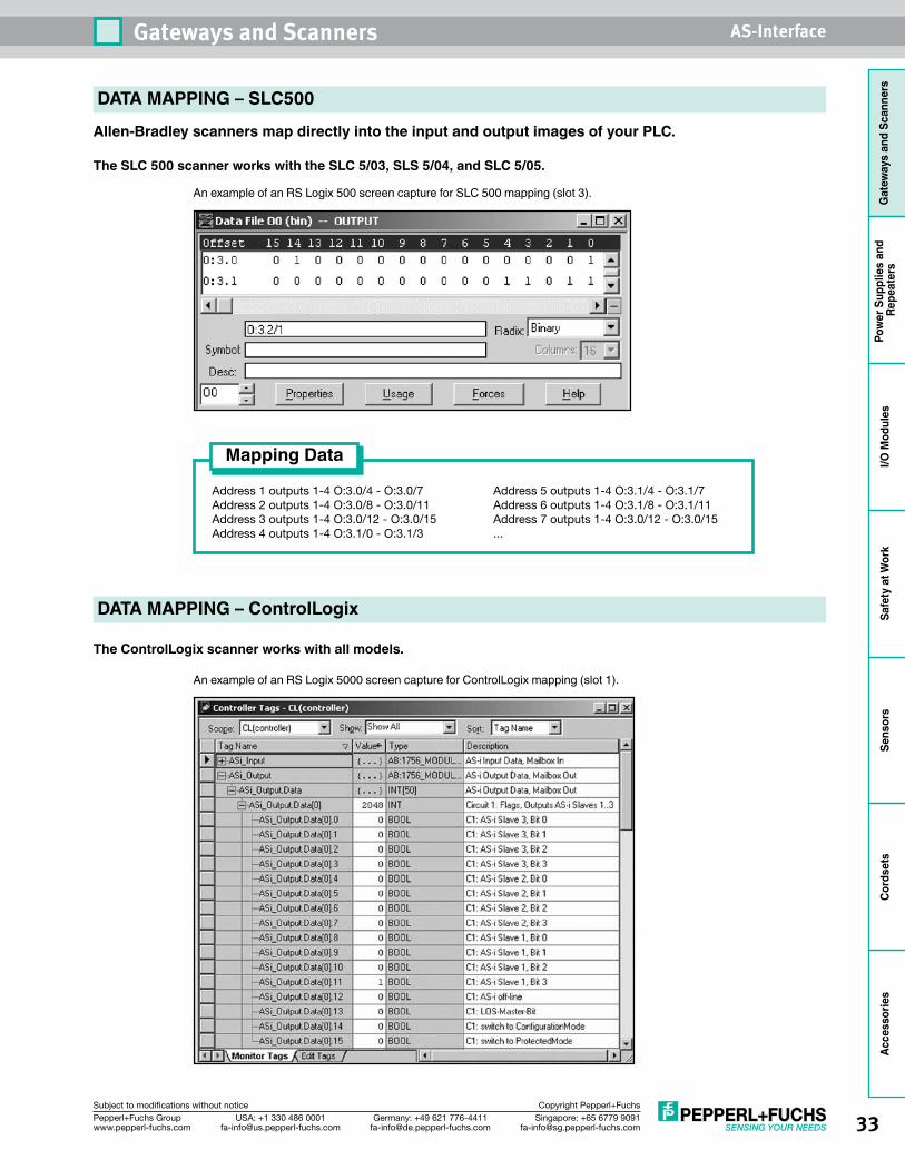
33Singapore: +65 6779 [email protected]
USA: +1 330 486 [email protected]
Germany: +49 621 [email protected]
Pepperl+Fuchs Groupwww.pepperl-fuchs.com
Subject to modifications without notice Copyright Pepperl+Fuchs
Gateways and Scanners AS-Interface
Gat
eway
s an
d Sc
anne
rsPo
wer
Sup
plie
s an
d Re
peat
ers
I/O M
odul
esSa
fety
at W
ork
Sens
ors
Cord
sets
Acce
ssor
ies
DATA MAPPING – SLC500
Allen-Bradley scanners map directly into the input and output images of your PLC.
The SLC 500 scanner works with the SLC 5/03, SLS 5/04, and SLC 5/05.
An example of an RS Logix 500 screen capture for SLC 500 mapping (slot 3).
Address 1 outputs 1-4 O:3.0/4 - O:3.0/7 Address 5 outputs 1-4 O:3.1/4 - O:3.1/7 Address 2 outputs 1-4 O:3.0/8 - O:3.0/11 Address 6 outputs 1-4 O:3.1/8 - O:3.1/11 Address 3 outputs 1-4 O:3.0/12 - O:3.0/15 Address 7 outputs 1-4 O:3.0/12 - O:3.0/15 Address 4 outputs 1-4 O:3.1/0 - O:3.1/3 ...
Mapping Data
The ControlLogix scanner works with all models.
An example of an RS Logix 5000 screen capture for ControlLogix mapping (slot 1).
DATA MAPPING – ControlLogix
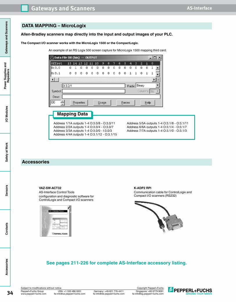
34 Singapore: +65 6779 [email protected]
USA: +1 330 486 [email protected]
Germany: +49 621 [email protected]
Pepperl+Fuchs Groupwww.pepperl-fuchs.com
Subject to modifications without notice Copyright Pepperl+Fuchs
Gateways and Scanners AS-InterfaceG
atew
ays
and
Scan
ners
Pow
er S
uppl
ies
and
Repe
ater
sI/O
Mod
ules
Safe
ty a
t Wor
kSe
nsor
sCo
rdse
tsAccessories
DATA MAPPING – MicroLogix
Allen-Bradley scanners map directly into the input and output images of your PLC.
The Compact I/O scanner works with the MicroLogix 1500 or the CompactLogix.
An example of an RS Logix 500 screen capture for MicroLogix 1500 mapping third card.
Address 1/1A outputs 1-4 O:3.0/8 - O:3.0/11 Address 5/5A outputs 1-4 O:3.1/8 - O:3.1/11 Address 2/2A outputs 1-4 O:3.0/4 - O:3.0/7 Address 6/6A outputs 1-4 O:3.1/4 - O:3.1/7 Address 3/3A outputs 1-4 O:3.0/0 - I:3.0/3 Address 7/7A outputs 1-4 O:3.1/0 - O:3.1/3 Address 4/4A outputs 1-4 O:3.1/12 - O:3.1/15
Mapping Data
Accessories
VAZ-SW-ACT32AS-Interface Control Tools configuration and diagnostic software for ControlLogix and Compact I/O scanners
K-ADP2 RPICommunication cable for ControlLogix and Compact I/O scanners (RS232)
See pages 211-226 for complete AS-Interface accessory listing.
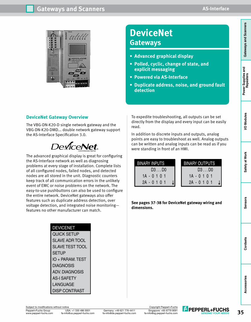
35Singapore: +65 6779 [email protected]
USA: +1 330 486 [email protected]
Germany: +49 621 [email protected]
Pepperl+Fuchs Groupwww.pepperl-fuchs.com
Subject to modifications without notice Copyright Pepperl+Fuchs
Gateways and Scanners AS-Interface
Gat
eway
s an
d Sc
anne
rsPo
wer
Sup
plie
s an
d Re
peat
ers
I/O M
odul
esSa
fety
at W
ork
Sens
ors
Cord
sets
Acce
ssor
ies
DeviceNet Gateway OverviewThe VBG-DN-K20-D single network gateway and the VBG-DN-K20-DMD... double network gateway support the AS-Interface Specification 3.0.
The advanced graphical display is great for configuring the AS-Interface network as well as diagnosing problems at every stage of installation. Complete lists of all configured nodes, failed nodes, and detected nodes are all stored in the unit. Diagnostic counters keep track of all communication errors in the unlikely event of EMC or noise problems on the network. The easy-to-use pushbuttons can also be used to configure the entire network. DeviceNet gateways also offer features such as duplicate address detection, over voltage detection, and integrated noise monitoring—features no other manufacturer can match.
To expedite troubleshooting, all outputs can be set directly from the display and every input can be easily read.
In addition to discrete inputs and outputs, analog points are easy to troubleshoot as well. Analog outputs can be written and analog inputs can be read as if you were standing in front of an HMI.
Seepages37-38forDeviceNetgatewaywiringanddimensions.
DEVICENETQUICK SETUPSLAVE ADR TOOLSLAVE TEST TOOLSETUPIO + PARAM. TESTDIAGNOSISADV. DIAGNOSISAS-I SAFETYLANGUAGEDISP CONTRAST
BINARY INPUTS D3 . . . D0 1A - 0 1 0 1 2A - 0 1 0 1
BINARY OUTPUTS D3 . . . D0 1A - 0 1 0 1 2A - 0 1 0 1
DeviceNetGateways• Advancedgraphicaldisplay• Polled,cyclic,changeofstate,andexplicitmessaging
• PoweredviaAS-Interface• Duplicateaddress,noise,andgroundfault
detection
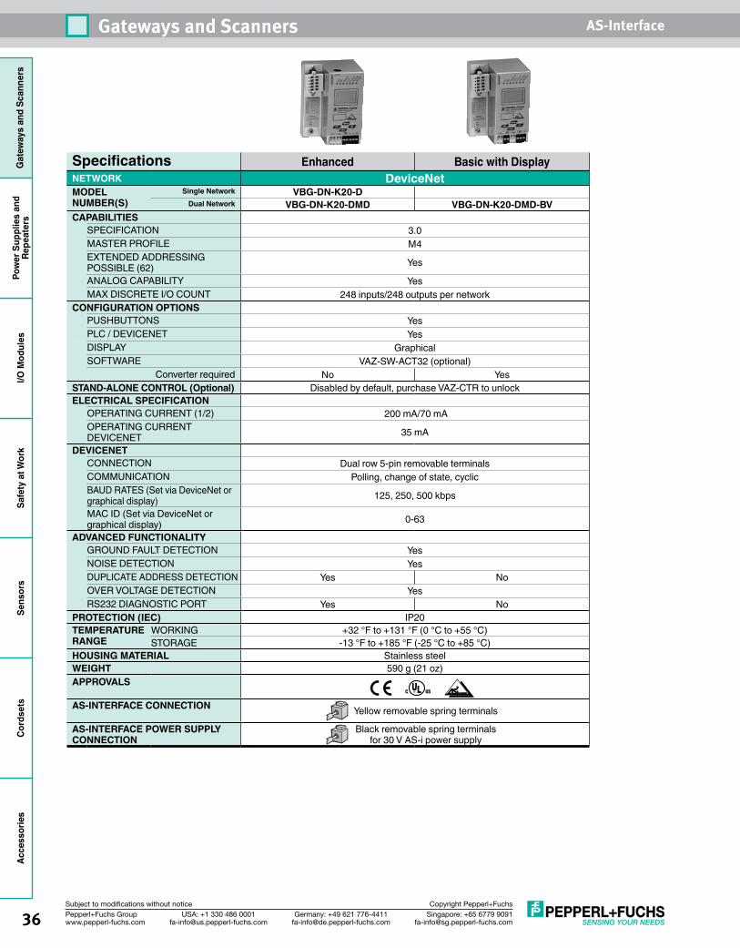
36 Singapore: +65 6779 [email protected]
USA: +1 330 486 [email protected]
Germany: +49 621 [email protected]
Pepperl+Fuchs Groupwww.pepperl-fuchs.com
Subject to modifications without notice Copyright Pepperl+Fuchs
Gateways and Scanners AS-InterfaceG
atew
ays
and
Scan
ners
Pow
er S
uppl
ies
and
Repe
ater
sI/O
Mod
ules
Safe
ty a
t Wor
kSe
nsor
sCo
rdse
tsAccessories
Specifications Enhanced Basic with DisplayNETWORK DeviceNetMODEL NUMBER(S)
Single Network VBG-DN-K20-DDual Network VBG-DN-K20-DMD VBG-DN-K20-DMD-BV
CAPABILITIESSPECIFICATION 3.0MASTER PROFILE M4EXTENDED ADDRESSING POSSIBLE (62) Yes
ANALOG CAPABILITY YesMAX DISCRETE I/O COUNT 248 inputs/248 outputs per network
CONFIGURATION OPTIONS PUSHBUTTONS YesPLC / DEVICENET YesDISPLAY GraphicalSOFTWARE VAZ-SW-ACT32 (optional)
Converter required No YesSTAND-ALONE CONTROL (Optional) Disabled by default, purchase VAZ-CTR to unlockELECTRICAL SPECIFICATION
OPERATING CURRENT (1/2) 200 mA/70 mAOPERATING CURRENT DEVICENET 35 mA
DEVICENETCONNECTION Dual row 5-pin removable terminalsCOMMUNICATION Polling, change of state, cyclicBAUD RATES (Set via DeviceNet or graphical display) 125, 250, 500 kbps
MAC ID (Set via DeviceNet or graphical display) 0-63
ADVANCED FUNCTIONALITYGROUND FAULT DETECTION YesNOISE DETECTION YesDUPLICATE ADDRESS DETECTION Yes NoOVER VOLTAGE DETECTION YesRS232 DIAGNOSTIC PORT Yes No
PROTECTION (IEC) IP20TEMPERATURE RANGE
WORKING +32 °F to +131 °F (0 °C to +55 °C)STORAGE -13 °F to +185 °F (-25 °C to +85 °C)
HOUSING MATERIAL Stainless steelWEIGHT 590 g (21 oz)APPROVALS
AS-INTERFACE CONNECTION Yellow removable spring terminals
AS-INTERFACE POWER SUPPLY CONNECTION
Black removable spring terminals for 30 V AS-i power supply
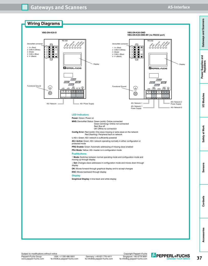
37Singapore: +65 6779 [email protected]
USA: +1 330 486 [email protected]
Germany: +49 621 [email protected]
Pepperl+Fuchs Groupwww.pepperl-fuchs.com
Subject to modifications without notice Copyright Pepperl+Fuchs
Gateways and Scanners AS-Interface
Gat
eway
s an
d Sc
anne
rsPo
wer
Sup
plie
s an
d Re
peat
ers
I/O M
odul
esSa
fety
at W
ork
Sens
ors
Cord
sets
Acce
ssor
ies
Wiring Diagrams
VBG-DN-K20-D VBG-DN-K20-DMDVBG-DN-K20-DMD-BV (no RS232 port)
Functional Ground
AS-i Network AS-i Power Supply
POWERMNS
CONFIG ERR
U AS-iAS-i A
CTIVE
PRG ENABLE
PRJ MODE
RS 232
Display
+ASI- +ASI- NC NC+PWR-ASI
OKESCMode
Set
DeviceNet connector
1 V+ (Red)2 CAN H (White)3 Shield4 CAN L (Blue)5 V- (Black)
POWERMNS
CONFIG ERR
U AS-iAS-i A
CTIVE
PRG ENABLE
PRJ MODE
RS 232
Display
+ASI- +PWR- +ASI2- +PWR-ASI2
OKESCMode
SetASI1Functional Ground
AS-i Network 1
AS-i Network 1Power Supply
AS-i Network 2 Power Supply
AS-i Network 2
DeviceNet connector
1 V+ (Red)2 CAN H (White)3 Shield4 CAN L (Blue)5 V- (Black)
LED IndicatorsPower: Green: Power onMNS: DeviceNet Status: Green (solid): Online connected
Green (brinking): Online not connected Red: Bus off Off: Offline no connection
Config Error: Red (solid): One slave missing or extra slave on the network Red (flashing): Peripheral fault on network
U AS-i: Green: AS-i network is sufficiently poweredAS-i Active: Green: AS-i network operating normally in either configuration or protected modePRG Enable: Green: Automatic addressing of missing slave enabledPRJ Mode: Yellow: AS-i master is in configuration mode
Pushbuttons↑ Mode: Switches between normal operating mode and configuration mode and moving up through display↓ Set: Changes slave addresses in configuration mode and moves down through displayOK: Moves forward through graphical display and to accept changesESC: Moves backward through display
DisplayGraphical Display: 4-line black and white display
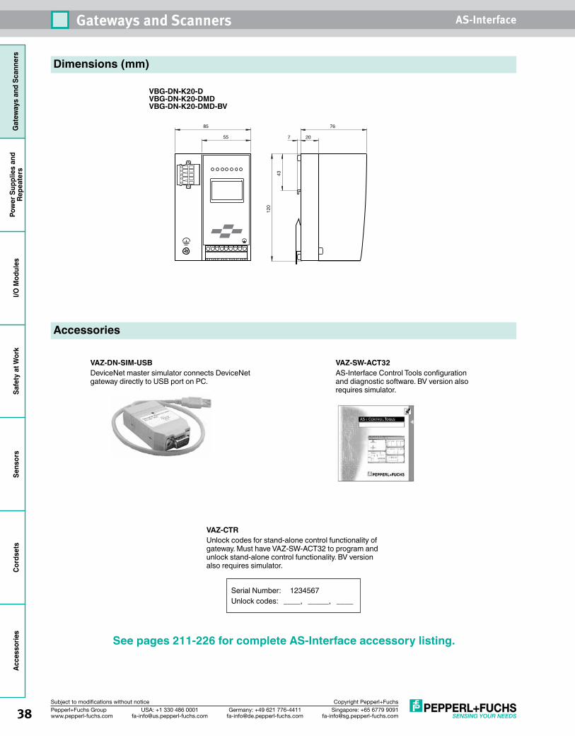
38 Singapore: +65 6779 [email protected]
USA: +1 330 486 [email protected]
Germany: +49 621 [email protected]
Pepperl+Fuchs Groupwww.pepperl-fuchs.com
Subject to modifications without notice Copyright Pepperl+Fuchs
Gateways and Scanners AS-InterfaceG
atew
ays
and
Scan
ners
Pow
er S
uppl
ies
and
Repe
ater
sI/O
Mod
ules
Safe
ty a
t Wor
kSe
nsor
sCo
rdse
tsAccessories
Dimensions (mm)
VBG-DN-K20-DVBG-DN-K20-DMDVBG-DN-K20-DMD-BV
43
120
7 20
76
55
85
Accessories
VAZ-SW-ACT32AS-Interface Control Tools configuration and diagnostic software. BV version also requires simulator.
VAZ-DN-SIM-USBDeviceNet master simulator connects DeviceNet gateway directly to USB port on PC.
See pages 211-226 for complete AS-Interface accessory listing.
VAZ-CTRUnlock codes for stand-alone control functionality of gateway. Must have VAZ-SW-ACT32 to program and unlock stand-alone control functionality. BV version also requires simulator.
Serial Number: 1234567Unlock codes: ____, _____, ____
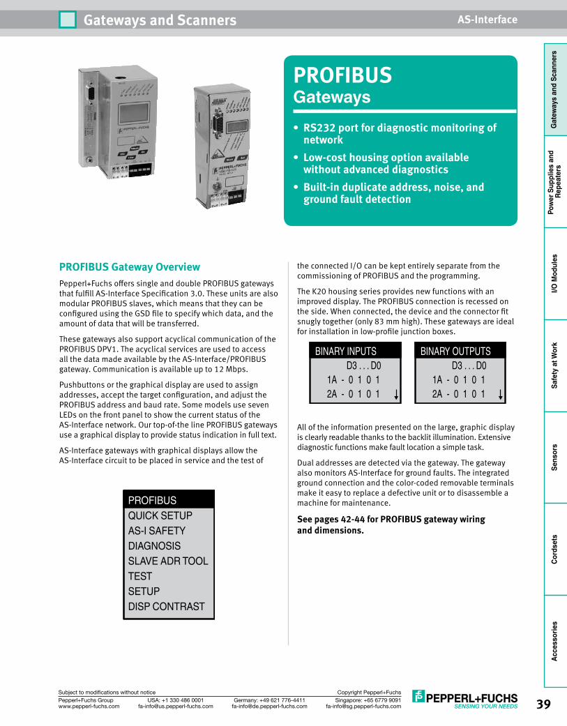
39Singapore: +65 6779 [email protected]
USA: +1 330 486 [email protected]
Germany: +49 621 [email protected]
Pepperl+Fuchs Groupwww.pepperl-fuchs.com
Subject to modifications without notice Copyright Pepperl+Fuchs
Gateways and Scanners AS-Interface
Gat
eway
s an
d Sc
anne
rsPo
wer
Sup
plie
s an
d Re
peat
ers
I/O M
odul
esSa
fety
at W
ork
Sens
ors
Cord
sets
Acce
ssor
ies
PROFIBUSGateways• RS232portfordiagnosticmonitoringofnetwork
• Low-costhousingoptionavailablewithout advanced diagnostics
• Built-induplicateaddress,noise,andground fault detection
PROFIBUS Gateway OverviewPepperl+Fuchs offers single and double PROFIBUS gateways that fulfill AS-Interface Specification 3.0. These units are also modular PROFIBUS slaves, which means that they can be configured using the GSD file to specify which data, and the amount of data that will be transferred.
These gateways also support acyclical communication of the PROFIBUS DPV1. The acyclical services are used to access all the data made available by the AS-Interface/PROFIBUS gateway. Communication is available up to 12 Mbps.
Pushbuttons or the graphical display are used to assign addresses, accept the target configuration, and adjust the PROFIBUS address and baud rate. Some models use seven LEDs on the front panel to show the current status of the AS-Interface network. Our top-of-the line PROFIBUS gateways use a graphical display to provide status indication in full text.
AS-Interface gateways with graphical displays allow the AS-Interface circuit to be placed in service and the test of
the connected I/O can be kept entirely separate from the commissioning of PROFIBUS and the programming.
The K20 housing series provides new functions with an improved display. The PROFIBUS connection is recessed on the side. When connected, the device and the connector fit snugly together (only 83 mm high). These gateways are ideal for installation in low-profile junction boxes.
All of the information presented on the large, graphic display is clearly readable thanks to the backlit illumination. Extensive diagnostic functions make fault location a simple task.
Dual addresses are detected via the gateway. The gateway also monitors AS-Interface for ground faults. The integrated ground connection and the color-coded removable terminals make it easy to replace a defective unit or to disassemble a machine for maintenance.
Seepages42-44forPROFIBUSgatewaywiring anddimensions.
BINARY INPUTS D3 . . . D0 1A - 0 1 0 1 2A - 0 1 0 1
BINARY OUTPUTS D3 . . . D0 1A - 0 1 0 1 2A - 0 1 0 1
PROFIBUSQUICK SETUPAS-I SAFETYDIAGNOSISSLAVE ADR TOOLTESTSETUPDISP CONTRAST
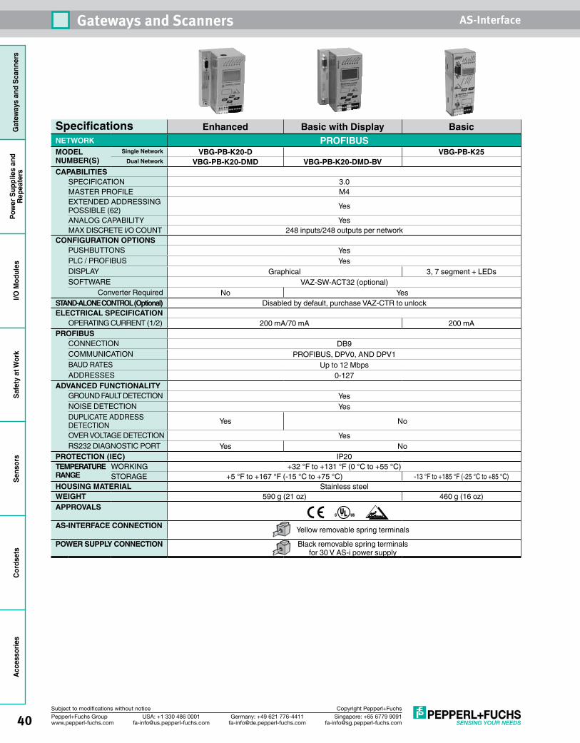
40 Singapore: +65 6779 [email protected]
USA: +1 330 486 [email protected]
Germany: +49 621 [email protected]
Pepperl+Fuchs Groupwww.pepperl-fuchs.com
Subject to modifications without notice Copyright Pepperl+Fuchs
Gateways and Scanners AS-InterfaceG
atew
ays
and
Scan
ners
Pow
er S
uppl
ies
and
Repe
ater
sI/O
Mod
ules
Safe
ty a
t Wor
kSe
nsor
sCo
rdse
tsAccessories
Specifications Enhanced Basic with Display Basic NETWORK PROFIBUSMODEL NUMBER(S)
Single Network VBG-PB-K20-D VBG-PB-K25Dual Network VBG-PB-K20-DMD VBG-PB-K20-DMD-BV
CAPABILITIESSPECIFICATION 3.0MASTER PROFILE M4EXTENDED ADDRESSING POSSIBLE (62) Yes
ANALOG CAPABILITY YesMAX DISCRETE I/O COUNT 248 inputs/248 outputs per network
CONFIGURATION OPTIONS PUSHBUTTONS YesPLC / PROFIBUS YesDISPLAY Graphical 3, 7 segment + LEDsSOFTWARE VAZ-SW-ACT32 (optional)
Converter Required No Yes STAND-ALONE CONTROL (Optional) Disabled by default, purchase VAZ-CTR to unlockELECTRICAL SPECIFICATION
OPERATING CURRENT (1/2) 200 mA/70 mA 200 mAPROFIBUS
CONNECTION DB9COMMUNICATION PROFIBUS, DPV0, AND DPV1BAUD RATES Up to 12 MbpsADDRESSES 0-127
ADVANCED FUNCTIONALITYGROUND FAULT DETECTION YesNOISE DETECTION Yes DUPLICATE ADDRESS DETECTION Yes No
OVER VOLTAGE DETECTION YesRS232 DIAGNOSTIC PORT Yes No
PROTECTION (IEC) IP20TEMPERATURE RANGE
WORKING +32 °F to +131 °F (0 °C to +55 °C)STORAGE +5 °F to +167 °F (-15 °C to +75 °C) -13 °F to +185 °F (-25 °C to +85 °C)
HOUSING MATERIAL Stainless steelWEIGHT 590 g (21 oz) 460 g (16 oz)APPROVALS
AS-INTERFACE CONNECTION Yellow removable spring terminals
POWER SUPPLY CONNECTION Black removable spring terminals for 30 V AS-i power supply
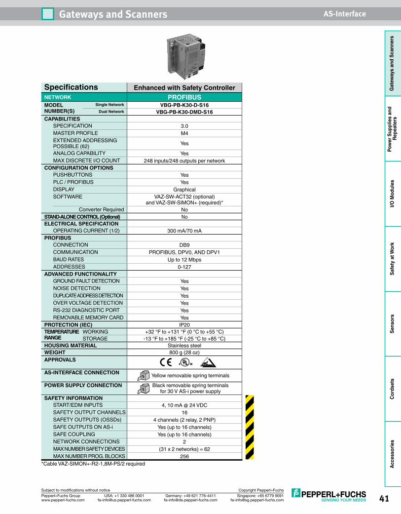
41Singapore: +65 6779 [email protected]
USA: +1 330 486 [email protected]
Germany: +49 621 [email protected]
Pepperl+Fuchs Groupwww.pepperl-fuchs.com
Subject to modifications without notice Copyright Pepperl+Fuchs
Gateways and Scanners AS-Interface
Gat
eway
s an
d Sc
anne
rsPo
wer
Sup
plie
s an
d Re
peat
ers
I/O M
odul
esSa
fety
at W
ork
Sens
ors
Cord
sets
Acce
ssor
ies
Specifications Enhanced with Safety ControllerNETWORK PROFIBUSMODEL NUMBER(S)
Single Network VBG-PB-K30-D-S16Dual Network VBG-PB-K30-DMD-S16
CAPABILITIESSPECIFICATION 3.0MASTER PROFILE M4EXTENDED ADDRESSING POSSIBLE (62) Yes
ANALOG CAPABILITY YesMAX DISCRETE I/O COUNT 248 inputs/248 outputs per network
CONFIGURATION OPTIONS PUSHBUTTONS YesPLC / PROFIBUS YesDISPLAY GraphicalSOFTWARE VAZ-SW-ACT32 (optional)
and VAZ-SW-SIMON+ (required)* Converter Required No
STAND-ALONE CONTROL (Optional) NoELECTRICAL SPECIFICATION
OPERATING CURRENT (1/2) 300 mA/70 mAPROFIBUS
CONNECTION DB9COMMUNICATION PROFIBUS, DPV0, AND DPV1BAUD RATES Up to 12 MbpsADDRESSES 0-127
ADVANCED FUNCTIONALITYGROUND FAULT DETECTION YesNOISE DETECTION YesDUPLICATE ADDRESS DETECTION YesOVER VOLTAGE DETECTION YesRS-232 DIAGNOSTIC PORT YesREMOVABLE MEMORY CARD Yes
PROTECTION (IEC) IP20TEMPERATURE RANGE
WORKING +32 °F to +131 °F (0 °C to +55 °C)STORAGE -13 °F to +185 °F (-25 °C to +85 °C)
HOUSING MATERIAL Stainless steelWEIGHT 800 g (28 oz)APPROVALS
AS-INTERFACE CONNECTION Yellow removable spring terminals
POWER SUPPLY CONNECTION Black removable spring terminals for 30 V AS-i power supply
SAFETY INFORMATION START/EDM INPUTS 4, 10 mA @ 24 VDCSAFETY OUTPUT CHANNELS 16 SAFETY OUTPUTS (OSSDs) 4 channels (2 relay, 2 PNP)SAFE OUTPUTS ON AS-i Yes (up to 16 channels) SAFE COUPLING Yes (up to 16 channels) NETWORK CONNECTIONS 2 MAX NUMBER SAFETY DEVICES (31 x 2 networks) = 62 MAX NUMBER PROG. BLOCKS 256
*Cable VAZ-SIMON+-R2-1,8M-PS/2 required
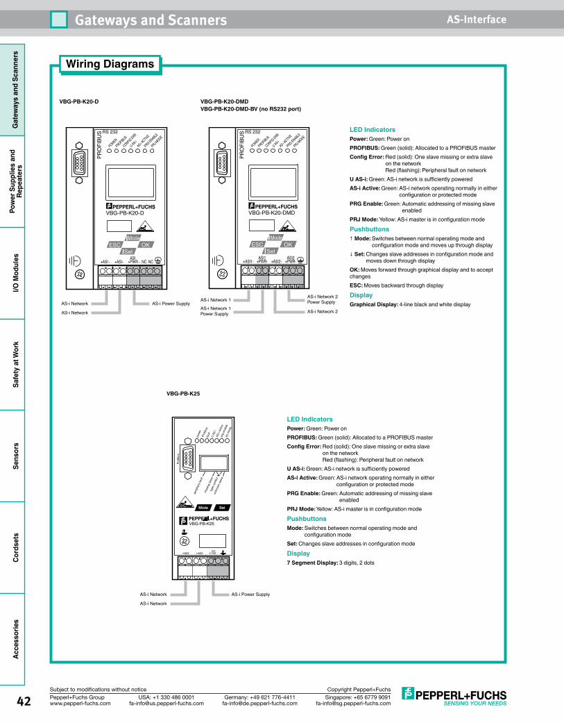
42 Singapore: +65 6779 [email protected]
USA: +1 330 486 [email protected]
Germany: +49 621 [email protected]
Pepperl+Fuchs Groupwww.pepperl-fuchs.com
Subject to modifications without notice Copyright Pepperl+Fuchs
Gateways and Scanners AS-InterfaceG
atew
ays
and
Scan
ners
Pow
er S
uppl
ies
and
Repe
ater
sI/O
Mod
ules
Safe
ty a
t Wor
kSe
nsor
sCo
rdse
tsAccessories
VBG-PB-K20-D VBG-PB-K20-DMD VBG-PB-K20-DMD-BV (no RS232 port)
POWERPROFIB
US
CONFIG ERR
U AS-iAS-i A
CTIVE
PRG ENABLE
PRJ MODE
VBG-PB-K20-DMD
RS 232
+ASI1- +PWR-ASI1
+ASI2- +PWR-ASI2
PRO
FIBU
SOKESC
Mode
Set
AS-i Network 1
AS-i Network 1Power Supply
AS-i Network 2 Power Supply
AS-i Network 2
POWERPROFIB
US
CONFIG ERR
U AS-iAS-i A
CTIVE
PRG ENABLE
PRJ MODE
VBG-PB-K20-D
RS 232
+ASI - +ASI- NC NC+PWR -ASI
PRO
FIBU
S
OKESCMode
Set
AS-i Network
AS-i Network
AS-i Power Supply
Wiring Diagrams
VBG-PB-K25
faul
tU
AS-i
powe
rPr
ofib
us
AS-
i act
ivepr
g en
able
prj m
ode
perip
hery
faul
tm
issin
g sla
veun
know
n sla
ve
type
con
flict
ASI+ - ASI+ -ASIPWR+ -
Prof
ibus
VBG-PB-K25
Mode Set
AS-i Power SupplyAS-i Network
AS-i Network
LED IndicatorsPower: Green: Power onPROFIBUS: Green (solid): Allocated to a PROFIBUS masterConfig Error: Red (solid): One slave missing or extra slave
on the network Red (flashing): Peripheral fault on network
U AS-i: Green: AS-i network is sufficiently poweredAS-i Active: Green: AS-i network operating normally in either
configuration or protected modePRG Enable: Green: Automatic addressing of missing slave
enabledPRJ Mode: Yellow: AS-i master is in configuration mode
PushbuttonsMode: Switches between normal operating mode and
configuration modeSet: Changes slave addresses in configuration mode
Display7 Segment Display: 3 digits, 2 dots
LED IndicatorsPower: Green: Power onPROFIBUS: Green (solid): Allocated to a PROFIBUS masterConfig Error: Red (solid): One slave missing or extra slave
on the network Red (flashing): Peripheral fault on network
U AS-i: Green: AS-i network is sufficiently poweredAS-i Active: Green: AS-i network operating normally in either
configuration or protected modePRG Enable: Green: Automatic addressing of missing slave
enabledPRJ Mode: Yellow: AS-i master is in configuration mode
Pushbuttons↑ Mode: Switches between normal operating mode and
configuration mode and moves up through display↓ Set: Changes slave addresses in configuration mode and
moves down through displayOK: Moves forward through graphical display and to accept changesESC: Moves backward through display
DisplayGraphical Display: 4-line black and white display
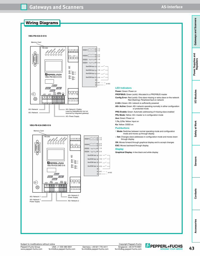
43Singapore: +65 6779 [email protected]
USA: +1 330 486 [email protected]
Germany: +49 621 [email protected]
Pepperl+Fuchs Groupwww.pepperl-fuchs.com
Subject to modifications without notice Copyright Pepperl+Fuchs
Gateways and Scanners AS-Interface
Gat
eway
s an
d Sc
anne
rsPo
wer
Sup
plie
s an
d Re
peat
ers
I/O M
odul
esSa
fety
at W
ork
Sens
ors
Cord
sets
Acce
ssor
ies
VBG-PB-K30-D-S16
+ASI1- +ASI1- +PWR-ASI1
24V 0V
AS-i Power Supply
VBG-PB-K30-D-S16
OKESCMode
Set
POWERPROFIB
US
CONFIG ERR
U AS-iAS-i A
CTIVE
PRG ENABLE
PRJ MODE
Aux
1.Y1
2.Y11.Y2
2.Y2
K1
K4K3
K2
1.13 0V 24V 2.13
1.14 3.14 4.14 2.14
2.Y2 + 2.Y1 +
+ 1.Y1 + 1.Y2
AS-i Network 2 Safety(used by SafetyMonitor but not scanned by integrated gateway)
RS 232
Memory Card
AS-i Network
AS-i Network
+ASI2-
Wiring Diagrams
LED IndicatorsPower: Green: Power onPROFIBUS: Green (solid): Allocated to a PROFIBUS masterConfig Error: Red (solid): One slave missing or extra slave on the network
Red (flashing): Peripheral fault on networkU AS-i: Green: AS-i network is sufficiently poweredAS-i Active: Green: AS-i network operating normally in either configuration
or protected modePRG Enable: Green: Automatic addressing of missing slave enabledPRJ Mode: Yellow: AS-i master is in configuration modeAux: Green: Power on 1.Yx, 2.Yx: Yellow: Input on Kx: Yellow: OSSD on
Pushbuttons↑ Mode: Switches between normal operating mode and configuration
mode and moves up through display↓ Set: Changes slave addresses in configuration mode and moves down
through displayOK: Moves forward through graphical display and to accept changesESC: Moves backward through display
DisplayGraphical Display: 4-line black and white display
1.131.14
2.132.14
1.Y2
Start/EDM Input
Start/EDM Input
Start/EDM Input
Start/EDM Input
1.Y1
2.Y2
2.Y1
OSSD1
1.13
2.13
OSSD2
OSSD3
OSSD4
+
24 V
0 V24 VDC
+
–
VBG-PB-K30-DMD-S16
+ASI1- +PWR-ASI1
+ASI2- +PWR-ASI2
VBG-PB-K30-DMD-S16
AS-i Network 1
AS-i Network 1Power Supply
AS-i Network 2 Power Supply
AS-i Network 2
OKESCMode
Set
POWERPROFIB
US
CONFIG ERR
U AS-iAS-i A
CTIVE
PRG ENABLE
PRJ MODE
Aux
1.Y1
2.Y11.Y2
2.Y2
K1
K4K3
K2
1.13 0V 24V 2.13
1.14 3.14 4.14 2.14
2.Y2 + 2.Y1 +
+ 1.Y1 + 1.Y2
RS 232
Memory Card
1.131.14
2.132.14
1.Y2
Start/EDM Input
Start/EDM Input
Start/EDM Input
Start/EDM Input
1.Y1
2.Y2
2.Y1
OSSD1
1.13
2.13
OSSD2
OSSD3
OSSD4
+
24 V
0 V24 VDC
+
–
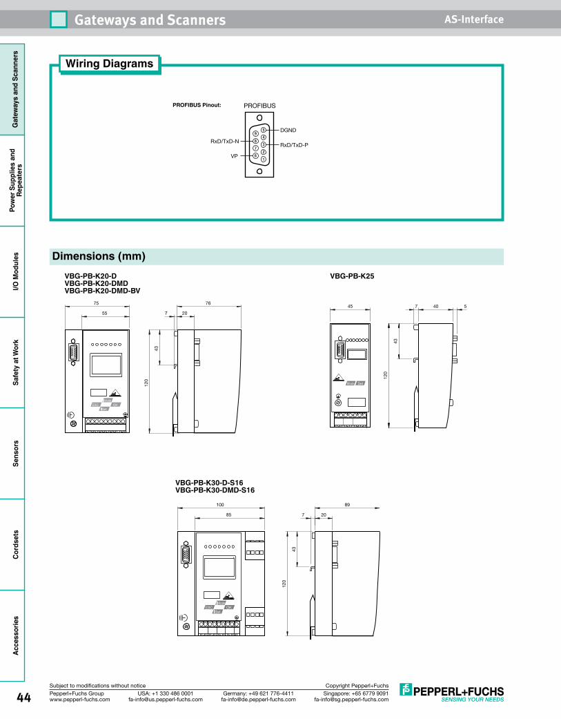
44 Singapore: +65 6779 [email protected]
USA: +1 330 486 [email protected]
Germany: +49 621 [email protected]
Pepperl+Fuchs Groupwww.pepperl-fuchs.com
Subject to modifications without notice Copyright Pepperl+Fuchs
Gateways and Scanners AS-InterfaceG
atew
ays
and
Scan
ners
Pow
er S
uppl
ies
and
Repe
ater
sI/O
Mod
ules
Safe
ty a
t Wor
kSe
nsor
sCo
rdse
tsAccessories
VBG-PB-K25VBG-PB-K20-DVBG-PB-K20-DMDVBG-PB-K20-DMD-BV
VBG-PB-K30-D-S16VBG-PB-K30-DMD-S16
Dimensions (mm)
43
120
7 20
76
55
75
OKESCMode
Set
43
120
7 40 545
Mode Set
OKESCMode
Set
85
100
20
89
7
43
120
Wiring Diagrams
PROFIBUS Pinout: PROFIBUS
5
4
3
2
1
9
8
7
6
RxD/TxD-P
VP
RxD/TxD-N
DGND
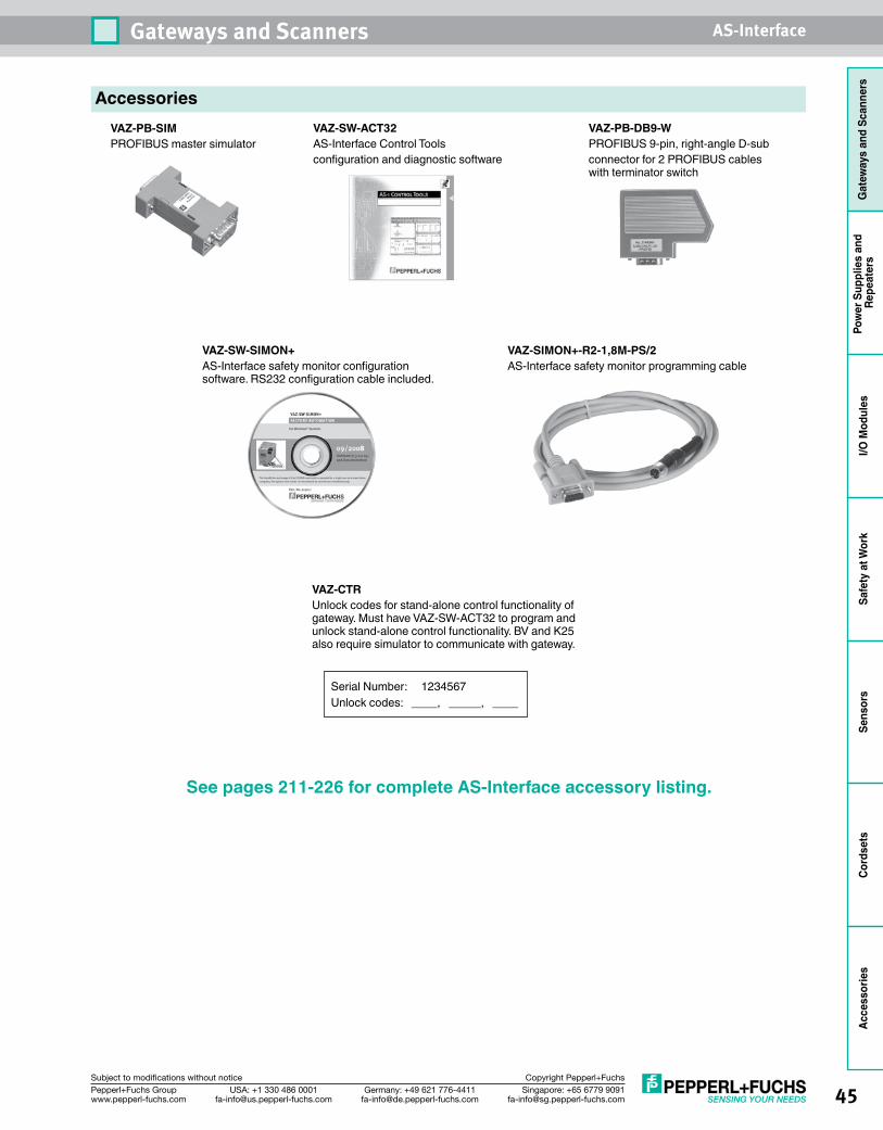
45Singapore: +65 6779 [email protected]
USA: +1 330 486 [email protected]
Germany: +49 621 [email protected]
Pepperl+Fuchs Groupwww.pepperl-fuchs.com
Subject to modifications without notice Copyright Pepperl+Fuchs
Gateways and Scanners AS-Interface
Gat
eway
s an
d Sc
anne
rsPo
wer
Sup
plie
s an
d Re
peat
ers
I/O M
odul
esSa
fety
at W
ork
Sens
ors
Cord
sets
Acce
ssor
ies
AccessoriesVAZ-PB-SIMPROFIBUS master simulator
VAZ-SW-ACT32AS-Interface Control Tools configuration and diagnostic software
VAZ-SW-SIMON+AS-Interface safety monitor configuration software. RS232 configuration cable included.
VAZ-PB-DB9-WPROFIBUS 9-pin, right-angle D-subconnector for 2 PROFIBUS cables with terminator switch
VAZ-CTRUnlock codes for stand-alone control functionality of gateway. Must have VAZ-SW-ACT32 to program and unlock stand-alone control functionality. BV and K25 also require simulator to communicate with gateway.
See pages 211-226 for complete AS-Interface accessory listing.
Serial Number: 1234567Unlock codes: ____, _____, ____
VAZ-SIMON+-R2-1,8M-PS/2AS-Interface safety monitor programming cable

46 Singapore: +65 6779 [email protected]
USA: +1 330 486 [email protected]
Germany: +49 621 [email protected]
Pepperl+Fuchs Groupwww.pepperl-fuchs.com
Subject to modifications without notice Copyright Pepperl+Fuchs
Gateways and Scanners AS-InterfaceG
atew
ays
and
Scan
ners
Pow
er S
uppl
ies
and
Repe
ater
sI/O
Mod
ules
Safe
ty a
t Wor
kSe
nsor
sCo
rdse
tsAccessories
EthernetGateways• RS232portfordiagnosticmonitoringofnetwork• Advancedgraphicaldisplay• Duplicateaddress,noise,andgroundfault
detection built in• 10/100MbpsEthernetconnection,IPaddresssetusingdisplayorDHCP
• Removablememorycard• Ethernet/IPsupportallowsdirectintegrationwithmodernAllen-BradleyPLCs
• IntegratedPROFINETandModbus/TCPprotocols• SafedatatransfertoPROFIsafe
OverviewPepperl+Fuchs offers gateways that function as complete AS-Interface networks and also as servers to the upper-level Ethernet networks. In configuration mode, all AS-Interface modules detected are displayed on the LCD. There are seven LEDs on the front panel available for diagnostics. Pushbuttons are used to program the addresses of the AS-Interface modules and to store the network configuration.
Each Ethernet gateway is supplied with a unique MAC-ID. An IP address can be assigned to the gateway using the graphical display or DHCP. All the information presented on the large, graphical display is clearly readable thanks to the backlit illumination. Extensive diagnostic functions make fault location a simple task.
Duplicate addresses are detected via the gateway. The gateway also monitors AS-Interface for ground faults. The integrated ground connection and the color-coded removable
terminals make it easy to replace a defective unit or disassemble a machine.
With direct Ethernet/IP, support integration of our Ethernet gateways into an Allen-Bradley ControlLogix or Compact I/O environment is easy and convenient. Once the gateway is inserted into the configuration, all I/O data is directly mapped and immediately available for use. The native implementations guarantee fast data updates. PROFINET is another Ethernet-based protocol predominately supported by many, including Siemens PLCs.
If Ethernet is used, Modbus/TCP is uniquely qualified to allow multiple users to log on simultaneously. This function enables one control program to be used alongside data acquisition, diagnostic, and monitoring software.
Seepages49-50forEthernetgatewaywiringanddimensions.
BINARY INPUTS D3 . . . D0 1A - 0 1 0 1 2A - 0 1 0 1
BINARY OUTPUTS D3 . . . D0 1A - 0 1 0 1 2A - 0 1 0 1
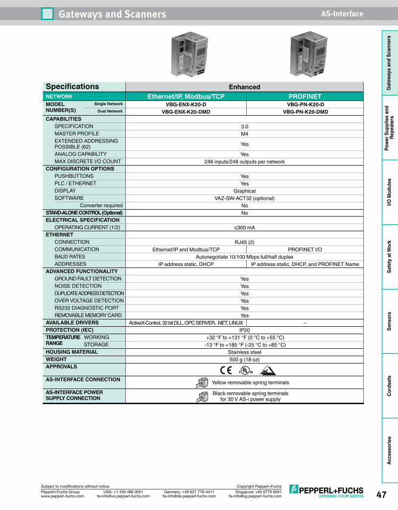
47Singapore: +65 6779 [email protected]
USA: +1 330 486 [email protected]
Germany: +49 621 [email protected]
Pepperl+Fuchs Groupwww.pepperl-fuchs.com
Subject to modifications without notice Copyright Pepperl+Fuchs
Gateways and Scanners AS-Interface
Gat
eway
s an
d Sc
anne
rsPo
wer
Sup
plie
s an
d Re
peat
ers
I/O M
odul
esSa
fety
at W
ork
Sens
ors
Cord
sets
Acce
ssor
ies
Specifications EnhancedNETWORK Ethernet/IP, Modbus/TCP PROFINETMODEL NUMBER(S)
Single Network VBG-ENX-K20-D VBG-PN-K20-DDual Network VBG-ENX-K20-DMD VBG-PN-K20-DMD
CAPABILITIESSPECIFICATION 3.0MASTER PROFILE M4EXTENDED ADDRESSING POSSIBLE (62) Yes
ANALOG CAPABILITY YesMAX DISCRETE I/O COUNT 248 inputs/248 outputs per network
CONFIGURATION OPTIONS PUSHBUTTONS YesPLC / ETHERNET YesDISPLAY GraphicalSOFTWARE VAZ-SW-ACT32 (optional)
Converter required NoSTAND-ALONE CONTROL (Optional) NoELECTRICAL SPECIFICATION
OPERATING CURRENT (1/2) ≤300 mAETHERNET
CONNECTION RJ45 (2)COMMUNICATION Ethernet/IP and Modbus/TCP PROFINET I/OBAUD RATES Autonegotiate 10/100 Mbps full/half duplexADDRESSES IP address static, DHCP IP address static, DHCP, and PROFINET Name
ADVANCED FUNCTIONALITYGROUND FAULT DETECTION YesNOISE DETECTION YesDUPLICATE ADDRESS DETECTION YesOVER VOLTAGE DETECTION YesRS232 DIAGNOSTIC PORT YesREMOVABLE MEMORY CARD Yes
AVAILABLE DRIVERS ActiveX-Control, 32 bit DLL, OPC SERVER, .NET, LINUX –PROTECTION (IEC) IP20TEMPERATURE RANGE
WORKING +32 °F to +131 °F (0 °C to +55 °C)STORAGE -13 °F to +185 °F (-25 °C to +85 °C)
HOUSING MATERIAL Stainless steelWEIGHT 500 g (18 oz)APPROVALS
AS-INTERFACE CONNECTION Yellow removable spring terminals
AS-INTERFACE POWER SUPPLY CONNECTION
Black removable spring terminals for 30 V AS-i power supply
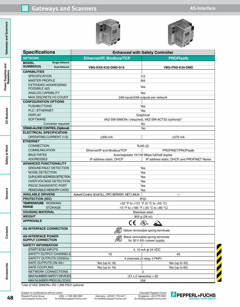
48 Singapore: +65 6779 [email protected]
USA: +1 330 486 [email protected]
Germany: +49 621 [email protected]
Pepperl+Fuchs Groupwww.pepperl-fuchs.com
Subject to modifications without notice Copyright Pepperl+Fuchs
Gateways and Scanners AS-InterfaceG
atew
ays
and
Scan
ners
Pow
er S
uppl
ies
and
Repe
ater
sI/O
Mod
ules
Safe
ty a
t Wor
kSe
nsor
sCo
rdse
tsAccessories
Specifications Enhanced with Safety ControllerNETWORK Ethernet/IP, Modbus/TCP PROFIsafeMODEL NUMBER(S)
Single Network Dual Network VBG-ENX-K30-DMD-S16 VBG-PNS-K30-DMD
CAPABILITIESSPECIFICATION 3.0 MASTER PROFILE M4 EXTENDED ADDRESSING POSSIBLE (62) Yes
ANALOG CAPABILITY Yes MAX DISCRETE I/O COUNT 248 inputs/248 outputs per network
CONFIGURATION OPTIONS PUSHBUTTONS Yes PLC / ETHERNET Yes DISPLAY Graphical SOFTWARE VAZ-SW-SIMON+ (required), VAZ-SW-ACT32 (optional)*
Converter required No STAND-ALONE CONTROL (Optional) NoELECTRICAL SPECIFICATION
OPERATING CURRENT (1/2) ≤300 mA ≤370 mAETHERNET
CONNECTION RJ45 (2)COMMUNICATION Ethernet/IP and Modbus/TCP PROFINET/PROFIsafe BAUD RATES Autonegotiate 10/100 Mbps full/half duplex ADDRESSES IP address static, DHCP IP address static, DHCP, and PROFINET Name
ADVANCED FUNCTIONALITYGROUND FAULT DETECTION Yes NOISE DETECTION Yes DUPLICATE ADDRESS DETECTION Yes OVER VOLTAGE DETECTION Yes RS232 DIAGNOSTIC PORT Yes REMOVABLE MEMORY CARD Yes
AVAILABLE DRIVERS ActiveX-Control, 32 bit DLL, OPC SERVER, .NET, LINUX — PROTECTION (IEC) IP20TEMPERATURE RANGE
WORKING +32 °F to +131 °F (0 °C to +55 °C)STORAGE -13 °F to +185 °F (-25 °C to +85 °C)
HOUSING MATERIAL Stainless steelWEIGHT 800 g (28 oz)APPROVALS
AS-INTERFACE CONNECTION Yellow removable spring terminals
AS-INTERFACE POWER SUPPLY CONNECTION
Black removable spring terminals for 30 V AS-i power supply
SAFETY INFORMATION START/EDM INPUTS 4, 10 mA @ 24 VDCSAFETY OUTPUT CHANNELS 16 45SAFETY OUTPUTS (OSSDs) 4 channels (2 relay, 2 PNP)SAFE OUTPUTS ON AS-i Yes (up to 16) Yes (up to 45)SAFE COUPLING Yes (up to 16) Yes (up to 62)NETWORK CONNECTIONS 2 MAX NUMBER SAFETY DEVICES (31 x 2 networks) = 62 MAX NUMBER PROG BLOCKS 256
*Use of VAZ-SIMON+-R2-1,8M-PS/2 optional
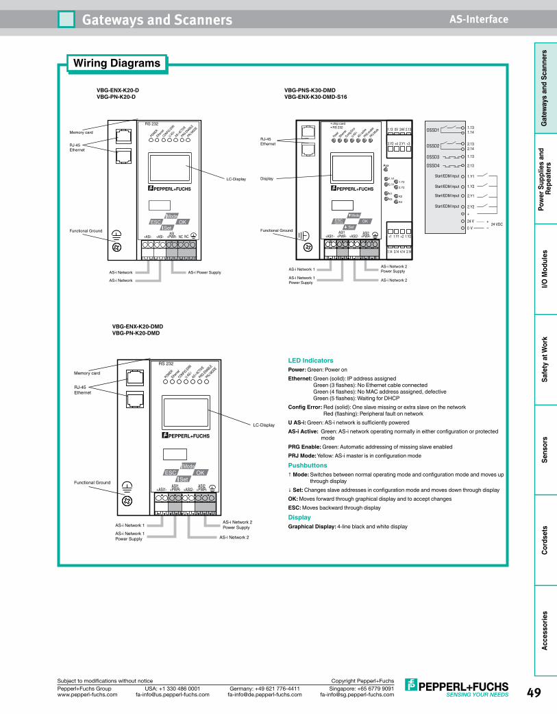
49Singapore: +65 6779 [email protected]
USA: +1 330 486 [email protected]
Germany: +49 621 [email protected]
Pepperl+Fuchs Groupwww.pepperl-fuchs.com
Subject to modifications without notice Copyright Pepperl+Fuchs
Gateways and Scanners AS-Interface
Gat
eway
s an
d Sc
anne
rsPo
wer
Sup
plie
s an
d Re
peat
ers
I/O M
odul
esSa
fety
at W
ork
Sens
ors
Cord
sets
Acce
ssor
ies
Wiring Diagrams
VBG-ENX-K20-D VBG-PN-K20-D
VBG-PNS-K30-DMD VBG-ENX-K30-DMD-S16
VBG-ENX-K20-DMD VBG-PN-K20-DMD
Memory card
Functional Ground
AS-i Network
AS-i Network
AS-i Power Supply
POWER
Etherne
t
CONFIG ERR
U AS-iAS-i A
CTIVE
PRG ENABLE
PRJ MODE
RS 232
RJ-45Ethernet
LC-Display
+ASI- +ASI- NC NC+PWR-ASI
OKESCMode
Set Functional Ground
RJ-45Ethernet
Display
+ASI1- +PWR- +ASI2- +PWR-ASI2
AS-i Network 1AS-i Network 2Power Supply
AS-i Network 1Power Supply
AS-i Network 2
ASI1
OKESCMode
Set
PowerEthernet
Config Error
U AS-iAS-i a
ctive
PRG enable
PRJ Mode
Aux
1.Y1
2.Y11.Y2
2.Y2
K1
K4K3
K2
Service
• chip card• RS 232
1.13 0V 24V 2.13
1.14 3.14 4.14 2.14
2.Y2 +4 2.Y1 +3
+1 1.Y1 +2 1.Y2
AS-i Network 1
AS-i Network 1Power Supply
AS-i Network 2 Power Supply
AS-i Network 2
+ASI1- +ASI2-+PWR-ASI1
+PWR-ASI2
POWER
Etherne
t
CONFIG ERR
U AS-iAS-i A
CTIVE
PRG ENABLE
PRJ MODE
RS 232
RJ-45Ethernet
LC-Display
OKESCMode
Set
Memory card
Functional Ground
LED IndicatorsPower: Green: Power onEthernet: Green (solid): IP address assigned
Green (3 flashes): No Ethernet cable connected Green (4 flashes): No MAC address assigned, defective Green (5 flashes): Waiting for DHCP
Config Error: Red (solid): One slave missing or extra slave on the network Red (flashing): Peripheral fault on network
U AS-i: Green: AS-i network is sufficiently poweredAS-i Active: Green: AS-i network operating normally in either configuration or protected modePRG Enable: Green: Automatic addressing of missing slave enabledPRJ Mode: Yellow: AS-i master is in configuration mode
Pushbuttons↑ Mode: Switches between normal operating mode and configuration mode and moves up
through display↓ Set: Changes slave addresses in configuration mode and moves down through displayOK: Moves forward through graphical display and to accept changesESC: Moves backward through display
DisplayGraphical Display: 4-line black and white display
1.131.14
2.132.14
1.Y2
Start/EDM Input
Start/EDM Input
Start/EDM Input
Start/EDM Input
1.Y1
2.Y2
2.Y1
OSSD1
1.13
2.13
OSSD2
OSSD3
OSSD4
+
24 V
0 V24 VDC
+
–
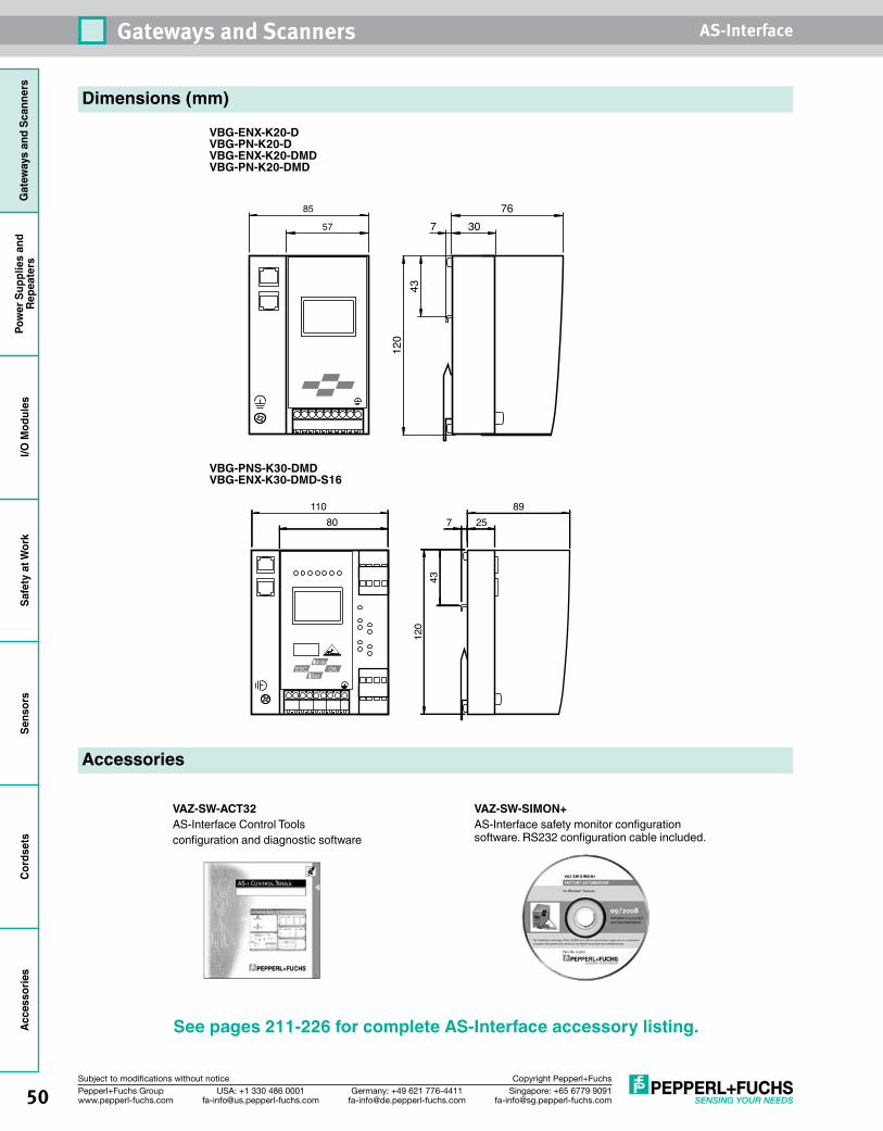
50 Singapore: +65 6779 [email protected]
USA: +1 330 486 [email protected]
Germany: +49 621 [email protected]
Pepperl+Fuchs Groupwww.pepperl-fuchs.com
Subject to modifications without notice Copyright Pepperl+Fuchs
Gateways and Scanners AS-InterfaceG
atew
ays
and
Scan
ners
Pow
er S
uppl
ies
and
Repe
ater
sI/O
Mod
ules
Safe
ty a
t Wor
kSe
nsor
sCo
rdse
tsAccessories
VBG-ENX-K20-DVBG-PN-K20-D VBG-ENX-K20-DMDVBG-PN-K20-DMD
Dimensions (mm)
43
120
7 30
76
57
85
See pages 211-226 for complete AS-Interface accessory listing.
Accessories
VAZ-SW-ACT32AS-Interface Control Tools configuration and diagnostic software
OKESCMode
Set
80110
2589
7
4312
0
VBG-PNS-K30-DMDVBG-ENX-K30-DMD-S16
VAZ-SW-SIMON+AS-Interface safety monitor configuration software. RS232 configuration cable included.
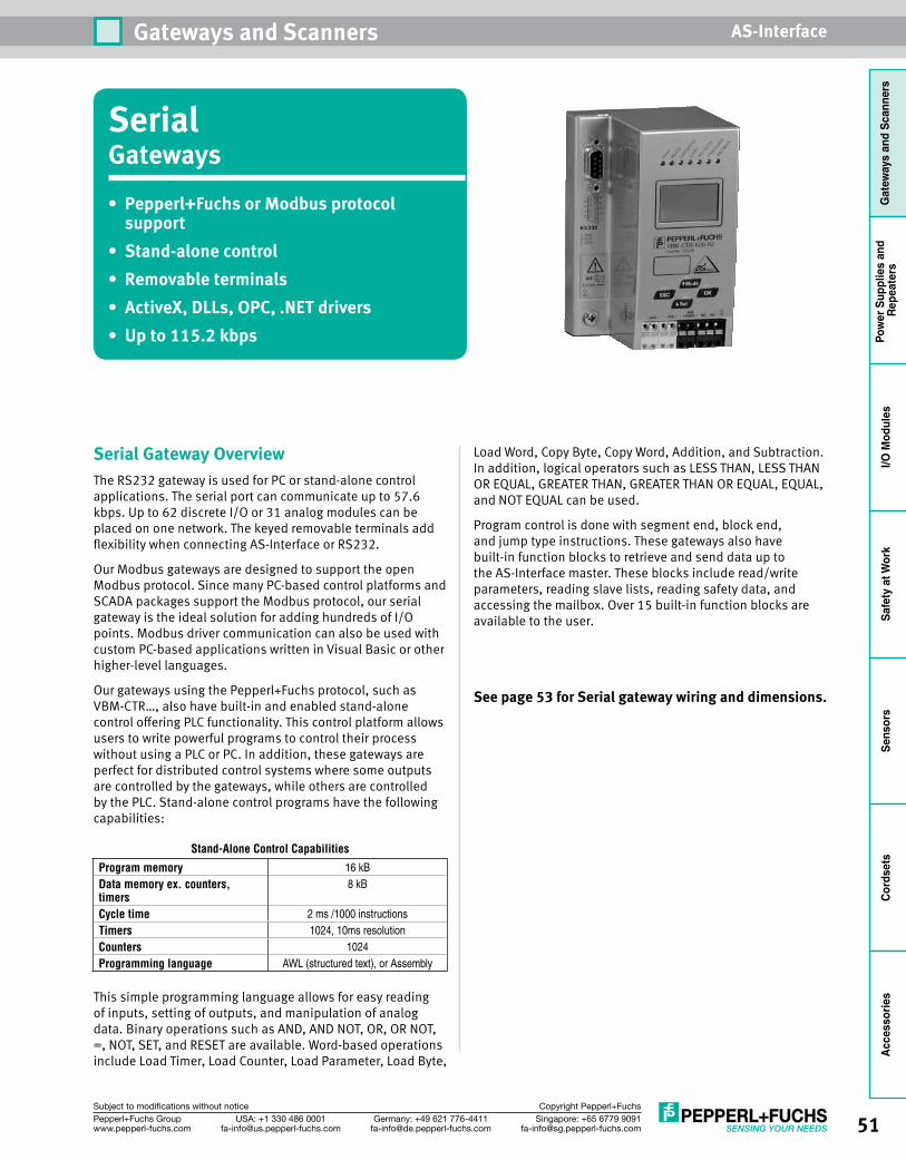
51Singapore: +65 6779 [email protected]
USA: +1 330 486 [email protected]
Germany: +49 621 [email protected]
Pepperl+Fuchs Groupwww.pepperl-fuchs.com
Subject to modifications without notice Copyright Pepperl+Fuchs
Gateways and Scanners AS-Interface
Gat
eway
s an
d Sc
anne
rsPo
wer
Sup
plie
s an
d Re
peat
ers
I/O M
odul
esSa
fety
at W
ork
Sens
ors
Cord
sets
Acce
ssor
ies
SerialGateways• Pepperl+FuchsorModbusprotocolsupport
• Stand-alonecontrol• Removableterminals• ActiveX,DLLs,OPC,.NETdrivers• Upto115.2kbps
Serial Gateway OverviewThe RS232 gateway is used for PC or stand-alone control applications. The serial port can communicate up to 57.6 kbps. Up to 62 discrete I/O or 31 analog modules can be placed on one network. The keyed removable terminals add flexibility when connecting AS-Interface or RS232.
Our Modbus gateways are designed to support the open Modbus protocol. Since many PC-based control platforms and SCADA packages support the Modbus protocol, our serial gateway is the ideal solution for adding hundreds of I/O points. Modbus driver communication can also be used with custom PC-based applications written in Visual Basic or other higher-level languages.
Our gateways using the Pepperl+Fuchs protocol, such as VBM-CTR…, also have built-in and enabled stand-alone control offering PLC functionality. This control platform allows users to write powerful programs to control their process without using a PLC or PC. In addition, these gateways are perfect for distributed control systems where some outputs are controlled by the gateways, while others are controlled by the PLC. Stand-alone control programs have the following capabilities:
Stand-Alone Control Capabilities
Program memory 16 kBData memory ex. counters, timers
8 kB
Cycle time 2 ms /1000 instructionsTimers 1024, 10ms resolutionCounters 1024Programming language AWL (structured text), or Assembly
This simple programming language allows for easy reading of inputs, setting of outputs, and manipulation of analog data. Binary operations such as AND, AND NOT, OR, OR NOT, =, NOT, SET, and RESET are available. Word-based operations include Load Timer, Load Counter, Load Parameter, Load Byte,
Load Word, Copy Byte, Copy Word, Addition, and Subtraction. In addition, logical operators such as LESS THAN, LESS THAN OR EQUAL, GREATER THAN, GREATER THAN OR EQUAL, EQUAL, and NOT EQUAL can be used.
Program control is done with segment end, block end, and jump type instructions. These gateways also have built-in function blocks to retrieve and send data up to the AS-Interface master. These blocks include read/write parameters, reading slave lists, reading safety data, and accessing the mailbox. Over 15 built-in function blocks are available to the user.
Seepage53forSerialgatewaywiringanddimensions.
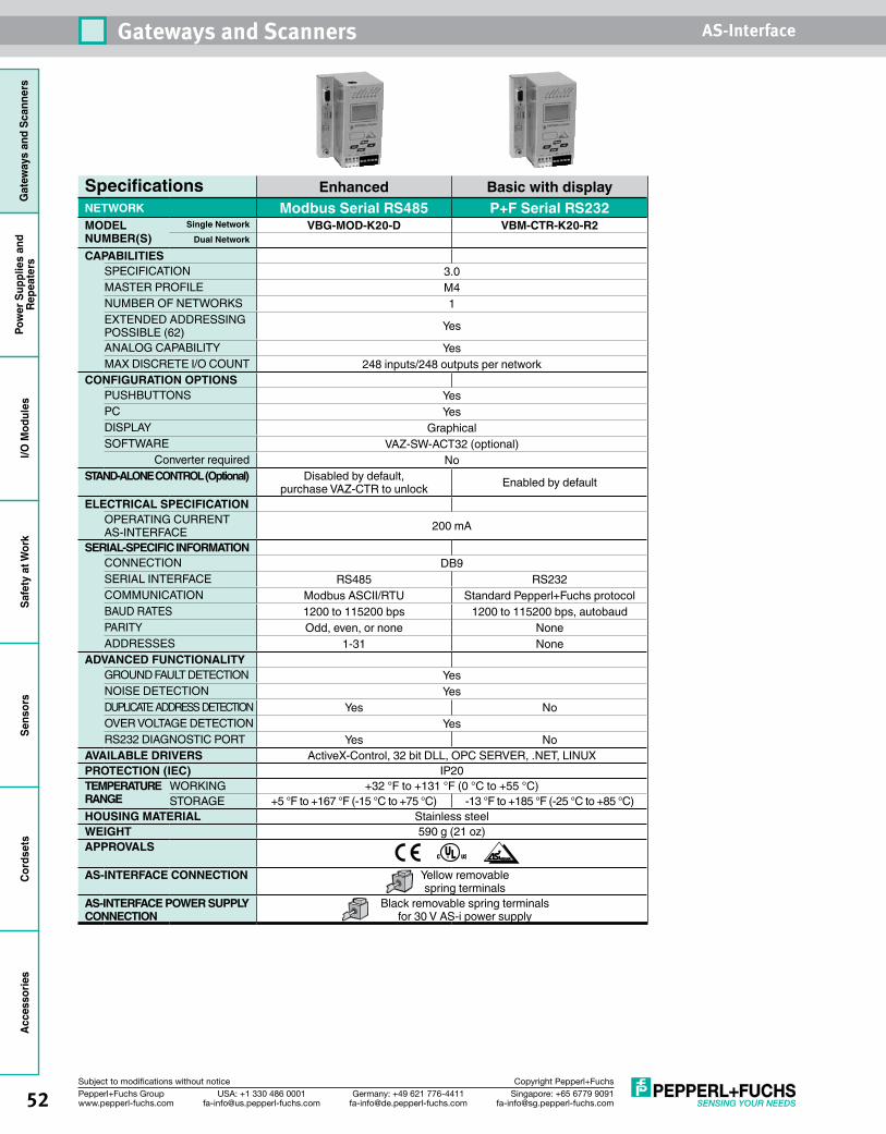
52 Singapore: +65 6779 [email protected]
USA: +1 330 486 [email protected]
Germany: +49 621 [email protected]
Pepperl+Fuchs Groupwww.pepperl-fuchs.com
Subject to modifications without notice Copyright Pepperl+Fuchs
Gateways and Scanners AS-InterfaceG
atew
ays
and
Scan
ners
Pow
er S
uppl
ies
and
Repe
ater
sI/O
Mod
ules
Safe
ty a
t Wor
kSe
nsor
sCo
rdse
tsAccessories
Specifications Enhanced Basic with displayNETWORK Modbus Serial RS485 P+F Serial RS232MODEL NUMBER(S)
Single Network VBG-MOD-K20-D VBM-CTR-K20-R2Dual Network
CAPABILITIESSPECIFICATION 3.0MASTER PROFILE M4NUMBER OF NETWORKS 1EXTENDED ADDRESSING POSSIBLE (62) Yes
ANALOG CAPABILITY YesMAX DISCRETE I/O COUNT 248 inputs/248 outputs per network
CONFIGURATION OPTIONS PUSHBUTTONS YesPC YesDISPLAY GraphicalSOFTWARE VAZ-SW-ACT32 (optional)
Converter required NoSTAND-ALONE CONTROL (Optional) Disabled by default,
purchase VAZ-CTR to unlock Enabled by default
ELECTRICAL SPECIFICATIONOPERATING CURRENT AS-INTERFACE 200 mA
SERIAL-SPECIFIC INFORMATIONCONNECTION DB9SERIAL INTERFACE RS485 RS232COMMUNICATION Modbus ASCII/RTU Standard Pepperl+Fuchs protocolBAUD RATES 1200 to 115200 bps 1200 to 115200 bps, autobaudPARITY Odd, even, or none NoneADDRESSES 1-31 None
ADVANCED FUNCTIONALITYGROUND FAULT DETECTION YesNOISE DETECTION YesDUPLICATE ADDRESS DETECTION Yes NoOVER VOLTAGE DETECTION YesRS232 DIAGNOSTIC PORT Yes No
AVAILABLE DRIVERS ActiveX-Control, 32 bit DLL, OPC SERVER, .NET, LINUXPROTECTION (IEC) IP20TEMPERATURE RANGE
WORKING +32 °F to +131 °F (0 °C to +55 °C)STORAGE +5 °F to +167 °F (-15 °C to +75 °C) -13 °F to +185 °F (-25 °C to +85 °C)
HOUSING MATERIAL Stainless steelWEIGHT 590 g (21 oz)APPROVALS
AS-INTERFACE CONNECTION Yellow removable spring terminals
AS-INTERFACE POWER SUPPLY CONNECTION
Black removable spring terminals for 30 V AS-i power supply
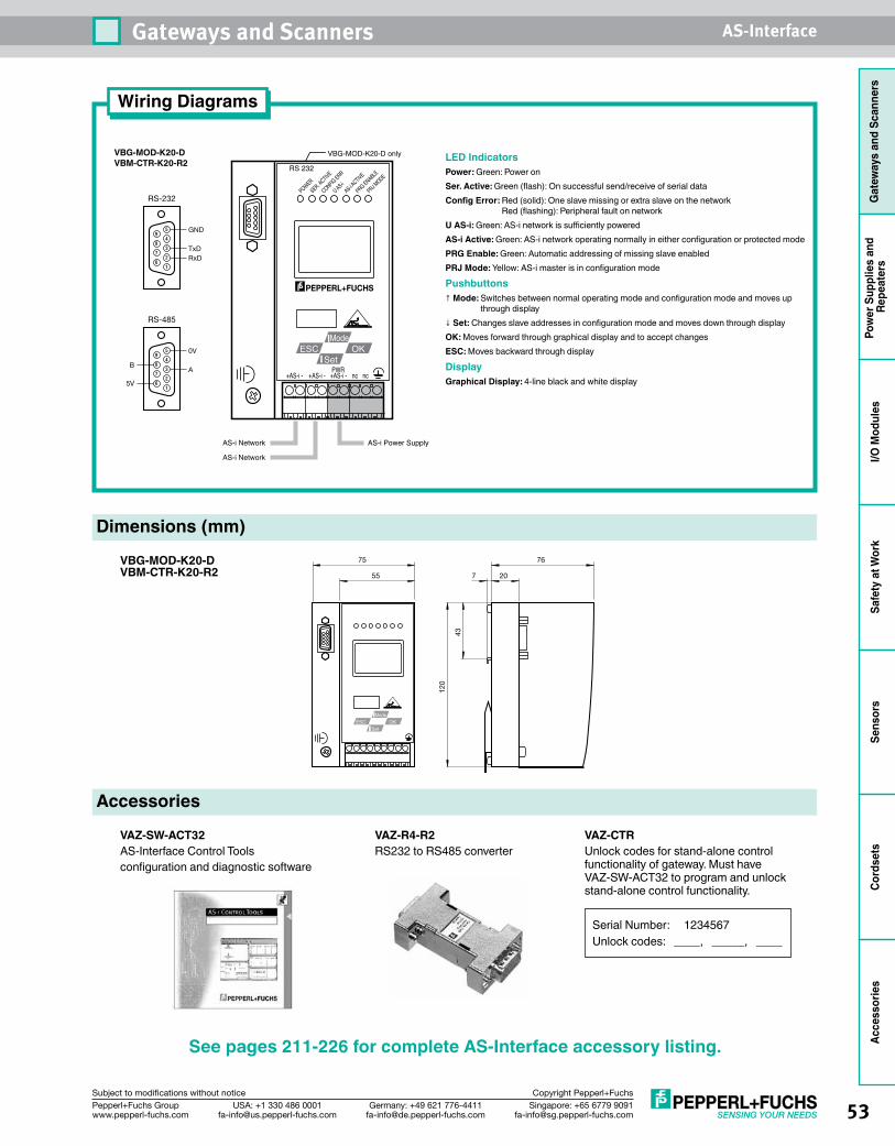
53Singapore: +65 6779 [email protected]
USA: +1 330 486 [email protected]
Germany: +49 621 [email protected]
Pepperl+Fuchs Groupwww.pepperl-fuchs.com
Subject to modifications without notice Copyright Pepperl+Fuchs
Gateways and Scanners AS-Interface
Gat
eway
s an
d Sc
anne
rsPo
wer
Sup
plie
s an
d Re
peat
ers
I/O M
odul
esSa
fety
at W
ork
Sens
ors
Cord
sets
Acce
ssor
ies
Wiring Diagrams
VBG-MOD-K20-D VBM-CTR-K20-R2
Dimensions (mm)
Accessories
43
120
7 20
76
55
75
OKESCMode
Set
POWERSER. ACTIV
E
CONFIG ERR
U AS-iAS-i A
CTIVE
PRG ENABLE
PRJ MODE
RS 232
+AS-i - +AS-i - nc nc+AS-i -PWR
OKESCMode
Set
AS-i Network
VBG-MOD-K20-D only
AS-i Power Supply
AS-i Network
VBG-MOD-K20-D VBM-CTR-K20-R2
LED IndicatorsPower: Green: Power onSer. Active: Green (flash): On successful send/receive of serial dataConfig Error: Red (solid): One slave missing or extra slave on the network
Red (flashing): Peripheral fault on networkU AS-i: Green: AS-i network is sufficiently poweredAS-i Active: Green: AS-i network operating normally in either configuration or protected modePRG Enable: Green: Automatic addressing of missing slave enabledPRJ Mode: Yellow: AS-i master is in configuration mode
Pushbuttons↑ Mode: Switches between normal operating mode and configuration mode and moves up
through display↓ Set: Changes slave addresses in configuration mode and moves down through displayOK: Moves forward through graphical display and to accept changesESC: Moves backward through display
DisplayGraphical Display: 4-line black and white display
RS-232
5
4
3
2
1
9
8
7
6
TxDRxD
GND
RS-485
5
4
3
2
1
9
8
7
6
A
0V
5V
B
See pages 211-226 for complete AS-Interface accessory listing.
VAZ-SW-ACT32AS-Interface Control Tools configuration and diagnostic software
VAZ-R4-R2 RS232 to RS485 converter
VAZ-CTRUnlock codes for stand-alone control functionality of gateway. Must have VAZ-SW-ACT32 to program and unlock stand-alone control functionality.
Serial Number: 1234567Unlock codes: ____, _____, ____
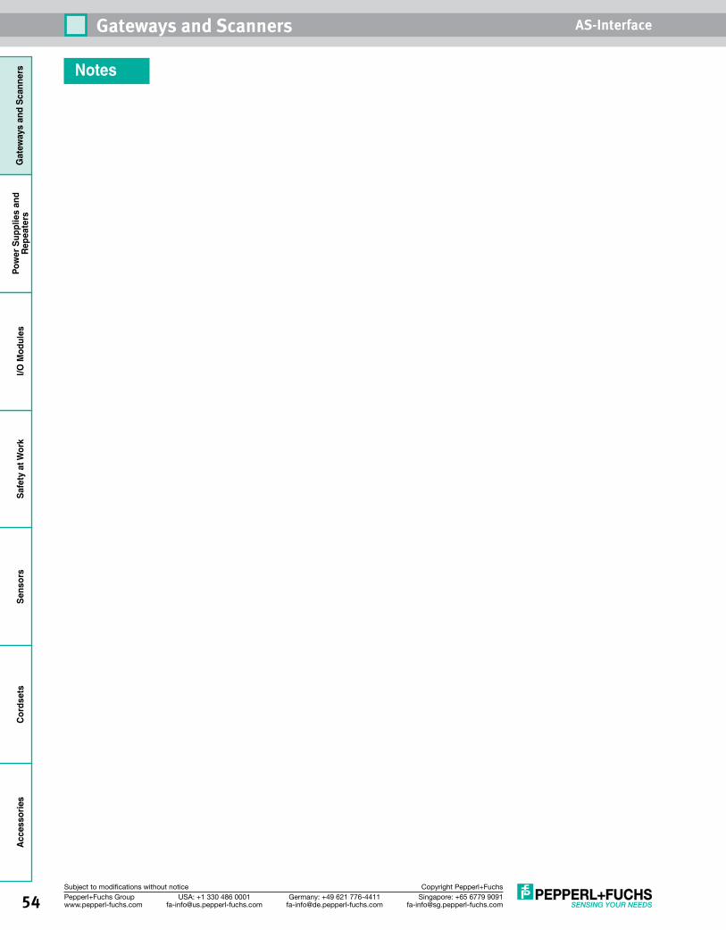
54 Singapore: +65 6779 [email protected]
USA: +1 330 486 [email protected]
Germany: +49 621 [email protected]
Pepperl+Fuchs Groupwww.pepperl-fuchs.com
Subject to modifications without notice Copyright Pepperl+Fuchs
Gateways and Scanners AS-InterfaceG
atew
ays
and
Scan
ners
Pow
er S
uppl
ies
and
Repe
ater
sI/O
Mod
ules
Safe
ty a
t Wor
kSe
nsor
sCo
rdse
tsAccessories
Notes
55Singapore: +65 6779 [email protected]
USA: +1 330 486 [email protected]
Germany: +49 621 [email protected]
Pepperl+Fuchs Groupwww.pepperl-fuchs.com
Subject to modifications without notice Copyright Pepperl+Fuchs
Power Supplies and Repeaters AS-Interface
Gat
eway
s an
d Sc
anne
rsPo
wer
Sup
plie
s an
d Re
peat
ers
I/O M
odul
esSa
fety
at W
ork
Sens
ors
Cord
sets
Acce
ssor
ies
Singapore: +65 6779 [email protected]
USA: +1 330 486 [email protected]
Germany: +49 621 [email protected]
Pepperl+Fuchs Groupwww.pepperl-fuchs.com
Subject to modifications without notice Copyright Pepperl+Fuchs
Power Supplies
and Repeaters
Power Supplies and RepeatersAS-Interface power supplies are an integral part of the AS-Interface network. On AS-Interface, data and power are transmitted on the same cable. The data signal is transferred using amplitude pulse modulation and rides on top of 30 VDC that powers the modules. Because both DC and high-frequency communication components are present on AS-Interface, power conditioning circuitry is required.
Features of AS-Interface Power SuppliesStartup and overload protectionAn overload can last for an indefinite amount of time without damaging the power supply. Removing the overload will allow the power supply to come back automatically to the the full-rated current.
Power specificationsThe output voltage of the power supply is between 29.5 VDC and 31.6 VDC over the entire load range.
Power interruptionsPower interruption of 10 ms or less on the primary side will not affect AS-Interface.
Power-on delayThe power-on delay is less than 2 s.
Rated Operating CurrentThe rated operating current can be exceeded by a maximum of 0.4 A to meet the expectations of the modules requiring extra current during power up.
AC input and AS-Interface output connections
Primary L Single phase N Neutral PE Protected earth ground AS-i+ AS-Interface Power + AS-i– AS-Interface Power – GND Machine ground and shield connection
Ground Fault DetectionAS-Interface (+) and AS-Interface (–) must never be grounded. In addition, they can never be connected to any load other than the appropriate terminals on AS-Interface I/O modules, AS-Interface intelligent sensors, or other loads. Standard PNP sensors are connected to AS-Interface through I/O modules. Grounding will reduce the noise immunity of the network. For this reason, ground fault detection supplies have been developed and will ensure that the AS-Interface network runs properly. This feature is also built into a number of AS-Interface gateways. Pepperl+Fuchs recommends using a power supply with ground fault detection when the scanner or gateway does not have integrated ground fault detection. We also recommend using these supplies in network segments after a repeater.
Choosing the Correct Power SupplyAS-Interface power supplies feature short-circuit and overload protection. In addition to providing power to the AS-Interface scanner/gateway, the AS-Interface power supply provides power to the electronics of the I/O modules and most inputs on the network. Modules
Primary
GND (screen)(PE)
PLV
AS-i +
AS-i –
CsCs
DCPowerSupply
PowerConditioning
Circuit
AS-Interface Power Supplies ........................... 58Power Conditioners ......................................... 61Repeaters ....................................................... 64Standard 24-30 VDC Power Supplies................ 67
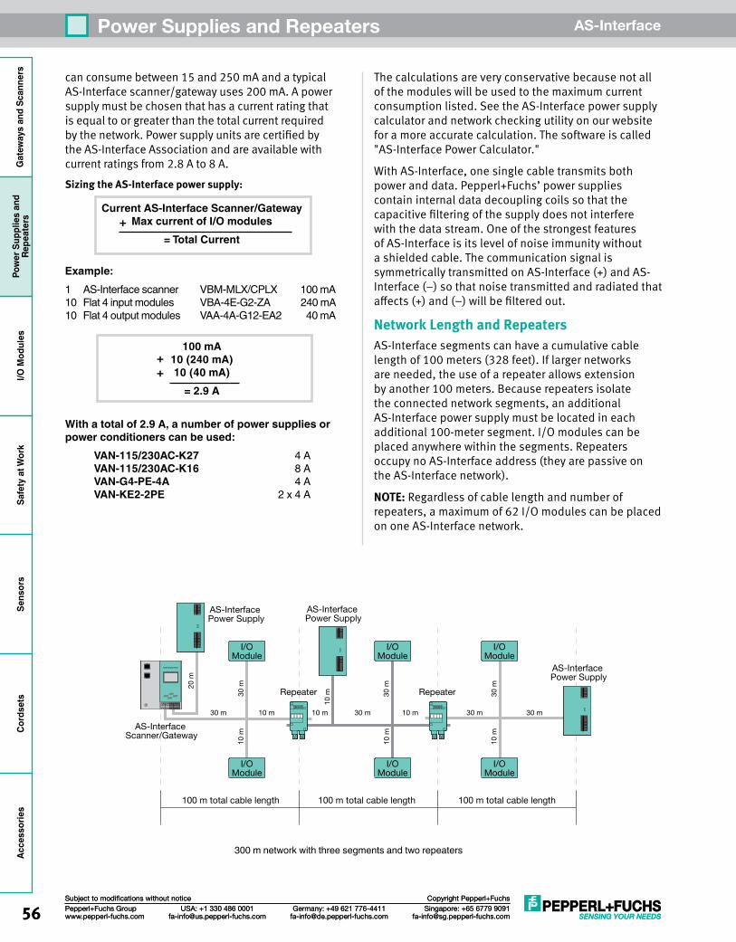
56 Singapore: +65 6779 [email protected]
USA: +1 330 486 [email protected]
Germany: +49 621 [email protected]
Pepperl+Fuchs Groupwww.pepperl-fuchs.com
Subject to modifications without notice Copyright Pepperl+Fuchs
Power Supplies and Repeaters AS-InterfaceG
atew
ays
and
Scan
ners
Pow
er S
uppl
ies
and
Repe
ater
sI/O
Mod
ules
Safe
ty a
t Wor
kSe
nsor
sCo
rdse
tsAc
cess
orie
s
56 Singapore: +65 6779 [email protected]
USA: +1 330 486 [email protected]
Germany: +49 621 [email protected]
Pepperl+Fuchs Groupwww.pepperl-fuchs.com
Subject to modifications without notice Copyright Pepperl+Fuchs
Power Supplies and Repeaters AS-Interface
can consume between 15 and 250 mA and a typical AS-Interface scanner/gateway uses 200 mA. A power supply must be chosen that has a current rating that is equal to or greater than the total current required by the network. Power supply units are certified by the AS-Interface Association and are available with current ratings from 2.8 A to 8 A.Sizing the AS-Interface power supply:
Current AS-Interface Scanner/Gateway Max current of I/O modules
= Total Current
Example:1 AS-Interface scanner VBM-MLX/CPLX 100 mA 10 Flat 4 input modules VBA-4E-G2-ZA 240 mA 10 Flat 4 output modules VAA-4A-G12-EA2 40 mA
100 mA 10 (240 mA) 10 (40 mA)
= 2.9 A
With a total of 2.9 A, a number of power supplies or power conditioners can be used:
VAN-115/230AC-K27 4 AVAN-115/230AC-K16 8 AVAN-G4-PE-4A 4 AVAN-KE2-2PE 2 x 4 A
The calculations are very conservative because not all of the modules will be used to the maximum current consumption listed. See the AS-Interface power supply calculator and network checking utility on our website for a more accurate calculation. The software is called "AS-Interface Power Calculator."
With AS-Interface, one single cable transmits both power and data. Pepperl+Fuchs’ power supplies contain internal data decoupling coils so that the capacitive filtering of the supply does not interfere with the data stream. One of the strongest features of AS-Interface is its level of noise immunity without a shielded cable. The communication signal is symmetrically transmitted on AS-Interface (+) and AS-Interface (–) so that noise transmitted and radiated that affects (+) and (–) will be filtered out.
Network Length and RepeatersAS-Interface segments can have a cumulative cable length of 100 meters (328 feet). If larger networks are needed, the use of a repeater allows extension by another 100 meters. Because repeaters isolate the connected network segments, an additional AS-Interface power supply must be located in each additional 100-meter segment. I/O modules can be placed anywhere within the segments. Repeaters occupy no AS-Interface address (they are passive on the AS-Interface network).
NOTE: Regardless of cable length and number of repeaters, a maximum of 62 I/O modules can be placed on one AS-Interface network.
I/OModule
I/OModule
I/OModule
I/OModule
I/OModule
I/OModule
Repeater Repeater
AS-Interface Power Supply
AS-Interface Scanner/Gateway
AS-Interface Power Supply
AS-Interface Power Supply
100 m total cable length
30 m 10 m 10 m 30 m 10 m 30 m 30 m
20 m
30 m
30 m
30 m
10 m
10 m
10 m
10 m
100 m total cable length 100 m total cable length
300 m network with three segments and two repeaters
+
++
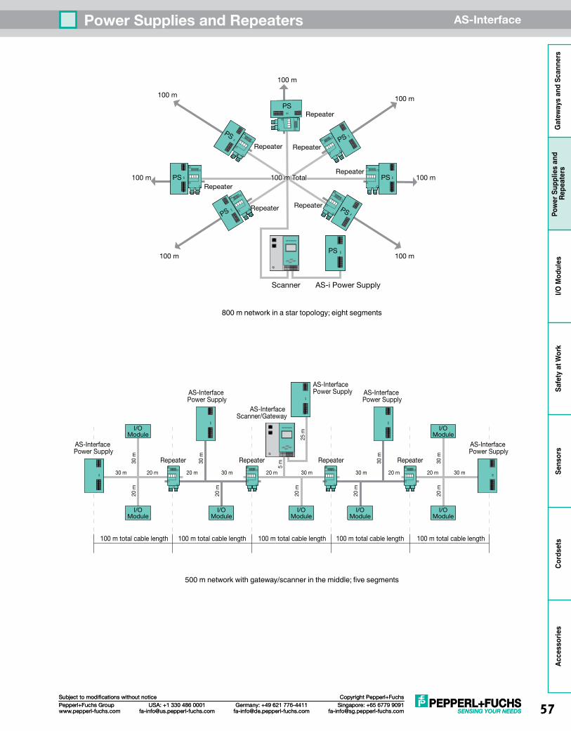
57Singapore: +65 6779 [email protected]
USA: +1 330 486 [email protected]
Germany: +49 621 [email protected]
Pepperl+Fuchs Groupwww.pepperl-fuchs.com
Subject to modifications without notice Copyright Pepperl+Fuchs
Power Supplies and Repeaters AS-Interface
Gat
eway
s an
d Sc
anne
rsPo
wer
Sup
plie
s an
d Re
peat
ers
I/O M
odul
esSa
fety
at W
ork
Sens
ors
Cord
sets
Acce
ssor
ies
57Singapore: +65 6779 [email protected]
USA: +1 330 486 [email protected]
Germany: +49 621 [email protected]
Pepperl+Fuchs Groupwww.pepperl-fuchs.com
Subject to modifications without notice Copyright Pepperl+Fuchs
Power Supplies and Repeaters AS-Interface
PS
RepeaterRepeater
RepeaterRepeater
Repeater100 m 100 m
100 m
100 m
100 m
100 m 100 m
Repeater
PSPS
PSPS
PS PS
Scanner AS-i Power Supply
100 m Total
RepeaterPS
PS
800 m network in a star topology; eight segments
I/OModule
I/OModule
I/OModule
I/OModule
I/OModule
I/OModule
I/OModule
AS-Interface Power Supply
AS-Interface Power Supply AS-Interface
Power SupplyAS-Interface Power Supply
AS-Interface Power Supply
AS-Interface Scanner/Gateway
30 m 30 m
30 m
30 m
30 m
5 m
20 m
30 m
20 m
20 m
20 m
20 m
25 m
20 m 20 m20 m 20 m30 m 30 m20 m 30 m
100 m total cable length100 m total cable length 100 m total cable length 100 m total cable length 100 m total cable length
Repeater Repeater Repeater Repeater
500 m network with gateway/scanner in the middle; five segments
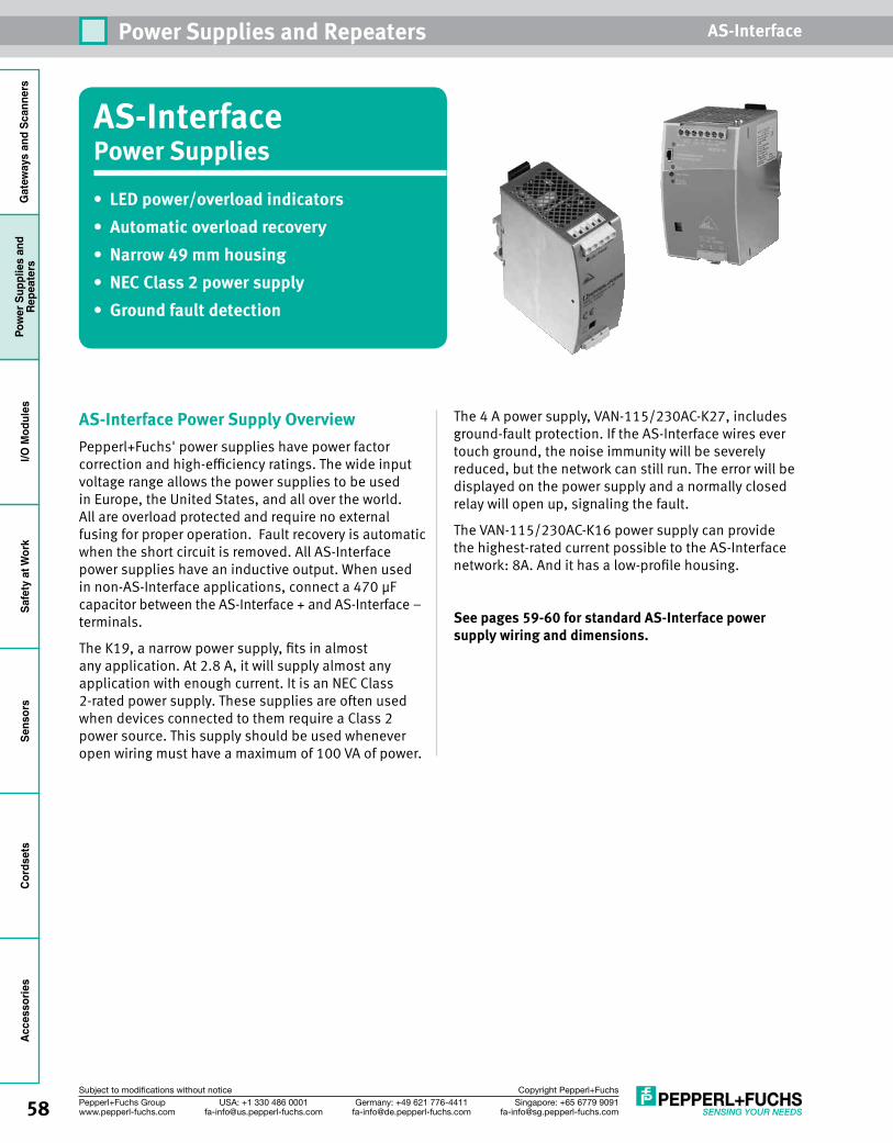
58 Singapore: +65 6779 [email protected]
USA: +1 330 486 [email protected]
Germany: +49 621 [email protected]
Pepperl+Fuchs Groupwww.pepperl-fuchs.com
Subject to modifications without notice Copyright Pepperl+Fuchs
Power Supplies and Repeaters AS-InterfaceG
atew
ays
and
Scan
ners
Pow
er S
uppl
ies
and
Repe
ater
sI/O
Mod
ules
Safe
ty a
t Wor
kSe
nsor
sCo
rdse
tsAc
cess
orie
s
AS-InterfacePower Supplies • LED power/overload indicators• Automatic overload recovery• Narrow 49 mm housing• NEC Class 2 power supply• Ground fault detection
AS-Interface Power Supply OverviewPepperl+Fuchs' power supplies have power factor correction and high-efficiency ratings. The wide input voltage range allows the power supplies to be used in Europe, the United States, and all over the world.All are overload protected and require no external fusing for proper operation. Fault recovery is automatic when the short circuit is removed. All AS-Interface power supplies have an inductive output. When used in non-AS-Interface applications, connect a 470 μF capacitor between the AS-Interface + and AS-Interface – terminals.
The K19, a narrow power supply, fits in almost any application. At 2.8 A, it will supply almost any application with enough current. It is an NEC Class 2-rated power supply. These supplies are often used when devices connected to them require a Class 2 power source. This supply should be used whenever open wiring must have a maximum of 100 VA of power.
The 4 A power supply, VAN-115/230AC-K27, includes ground-fault protection. If the AS-Interface wires ever touch ground, the noise immunity will be severely reduced, but the network can still run. The error will be displayed on the power supply and a normally closed relay will open up, signaling the fault.
The VAN-115/230AC-K16 power supply can provide the highest-rated current possible to the AS-Interface network: 8A. And it has a low-profile housing.
See pages 59-60 for standard AS-Interface power supply wiring and dimensions.
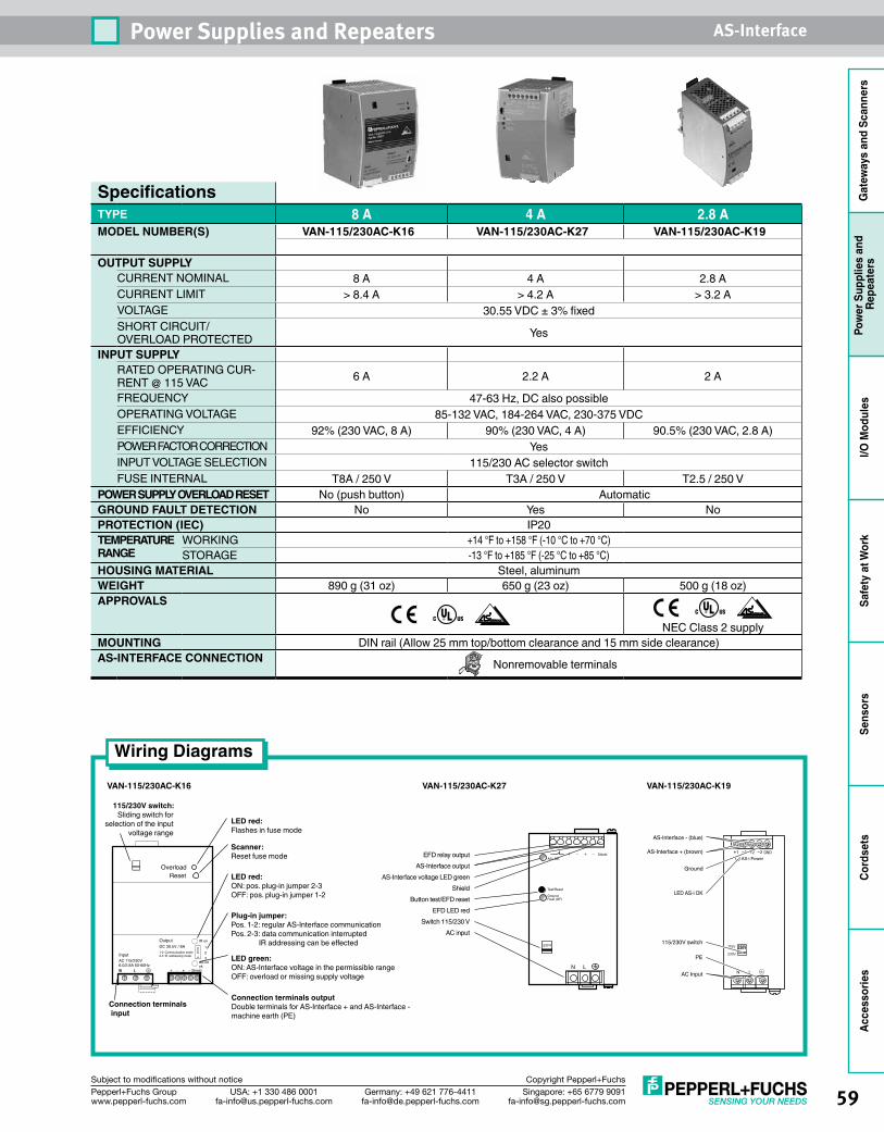
59Singapore: +65 6779 [email protected]
USA: +1 330 486 [email protected]
Germany: +49 621 [email protected]
Pepperl+Fuchs Groupwww.pepperl-fuchs.com
Subject to modifications without notice Copyright Pepperl+Fuchs
Power Supplies and Repeaters AS-Interface
Gat
eway
s an
d Sc
anne
rsPo
wer
Sup
plie
s an
d Re
peat
ers
I/O M
odul
esSa
fety
at W
ork
Sens
ors
Cord
sets
Acce
ssor
ies
SpecificationsTYPE 8 A 4 A 2.8 AMODEL NUMBER(S) VAN-115/230AC-K16 VAN-115/230AC-K27 VAN-115/230AC-K19
OUTPUT SUPPLYCURRENT NOMINAL 8 A 4 A 2.8 ACURRENT LIMIT > 8.4 A > 4.2 A > 3.2 AVOLTAGE 30.55 VDC ± 3% fixedSHORT CIRCUIT/ OVERLOAD PROTECTED Yes
INPUT SUPPLYRATED OPERATING CUR-RENT @ 115 VAC 6 A 2.2 A 2 A
FREQUENCY 47-63 Hz, DC also possibleOPERATING VOLTAGE 85-132 VAC, 184-264 VAC, 230-375 VDCEFFICIENCY 92% (230 VAC, 8 A) 90% (230 VAC, 4 A) 90.5% (230 VAC, 2.8 A)POWER FACTOR CORRECTION YesINPUT VOLTAGE SELECTION 115/230 AC selector switchFUSE INTERNAL T8A / 250 V T3A / 250 V T2.5 / 250 V
POWER SUPPLY OVERLOAD RESET No (push button) AutomaticGROUND FAULT DETECTION No Yes NoPROTECTION (IEC) IP20TEMPERATURE RANGE
WORKING +14 °F to +158 °F (-10 °C to +70 °C)STORAGE -13 °F to +185 °F (-25 °C to +85 °C)
HOUSING MATERIAL Steel, aluminumWEIGHT 890 g (31 oz) 650 g (23 oz) 500 g (18 oz)APPROVALS
NEC Class 2 supply
MOUNTING DIN rail (Allow 25 mm top/bottom clearance and 15 mm side clearance)AS-INTERFACE CONNECTION Nonremovable terminals
Wiring Diagrams
VAN-115/230AC-K16 VAN-115/230AC-K19
115/230V switch:Sliding switch for
selection of the input voltage range
Connection terminals input
LED red:Flashes in fuse mode
Scanner:Reset fuse mode
LED red:ON: pos. plug-in jumper 2-3OFF: pos. plug-in jumper 1-2
Plug-in jumper:Pos. 1-2: regular AS-Interface communicationPos. 2-3: data communication interrupted IR addressing can be effected
LED green:ON: AS-Interface voltage in the permissible rangeOFF: overload or missing supply voltage
Connection terminals outputDouble terminals for AS-Interface + and AS-Interface - machine earth (PE)
OverloadReset
IR on123
AS-intok
Shield+ - + -N L
1-2 Communication mode2-3 IR addressing mode
DC 30.5V / 8AOutput
AC 115/230V6.0/2.8A 50-60Hz
Input
VAN-115/230AC-K27
AC inputSwitch 115/230 V
EFD LED redButton test/EFD reset
AS-Interface voltage LED greenAS-Interface output
EFD relay output
Shield
AS-i OK
Test/Reset
GroundFault (GF)
Shield+ +- -
N L
230 V
LED AS-i OK
AS-Interface - (blue)
AS-Interface + (brown)
Ground
PE
AC Input
115/230V switch230V
2-2+1-
115V
230V
N
AS-i Power
L
GND1+
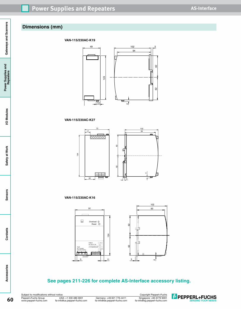
60 Singapore: +65 6779 [email protected]
USA: +1 330 486 [email protected]
Germany: +49 621 [email protected]
Pepperl+Fuchs Groupwww.pepperl-fuchs.com
Subject to modifications without notice Copyright Pepperl+Fuchs
Power Supplies and Repeaters AS-InterfaceG
atew
ays
and
Scan
ners
Pow
er S
uppl
ies
and
Repe
ater
sI/O
Mod
ules
Safe
ty a
t Wor
kSe
nsor
sCo
rdse
tsAc
cess
orie
s
VAN-115/230AC-K16
VAN-115/230AC-K19
Dimensions (mm)
VAN-115/230AC-K27
10294
6262
4
530
7317
124
See pages 211-226 for complete AS-Interface accessory listing.
94102 549
13
4212
4
4
6262
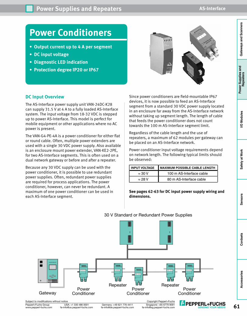
61Singapore: +65 6779 [email protected]
USA: +1 330 486 [email protected]
Germany: +49 621 [email protected]
Pepperl+Fuchs Groupwww.pepperl-fuchs.com
Subject to modifications without notice Copyright Pepperl+Fuchs
Power Supplies and Repeaters AS-Interface
Gat
eway
s an
d Sc
anne
rsPo
wer
Sup
plie
s an
d Re
peat
ers
I/O M
odul
esSa
fety
at W
ork
Sens
ors
Cord
sets
Acce
ssor
ies
DC Input OverviewThe AS-Interface power supply unit VAN-24DC-K28 can supply 31.5 V at 4 A to a fully loaded AS-Interface system. The input voltage from 18-32 VDC is stepped up to power AS-Interface. This model is perfect for mobile equipment or other applications where no AC power is present.
The VAN-G4-PE-4A is a power conditioner for either flat or round cable. Often, multiple power extenders are used with a single 30 VDC power supply. Also available is an enclosure mount power extender, VAN-KE2-2PE, for two AS-Interface segments. This is often used on a dual network gateway or before and after a repeater.
Because any 30 VDC supply can be used with the power conditioner, it is possible to use redundant power supplies. Often, redundant power supplies are required for process applications. The power conditioner, however, can never be redundant. A maximum of one power conditioner can be used in each AS-Interface segment.
Since power conditioners are field-mountable IP67 devices, it is now possible to feed an AS-Interface segment from a standard 30 VDC power supply located in an enclosure far away from the AS-Interface network without taking up segment length. The length of cable that feeds the power conditioner does not count towards the 100 m AS-Interface segment limit.
Regardless of the cable length and the use of repeaters, a maximum of 62 modules per gateway can be placed on an AS-Interface network.
Power conditioner input voltage requirements depend on network length. The following typical limits should be observed:
INPUT VOLTAGE MAXIMUM POSSIBLE CABLE LENGTH
≈ 30 V 100 m AS-Interface cable≈ 28 V 80 m AS-Interface cable
See pages 62-63 for DC input power supply wiring and dimensions.
Gateway
Repeater
30 V Standard or Redundant Power Supplies
PowerConditioner
PowerConditioner
RepeaterPower
Conditioner
Power Conditioners• Output current up to 4 A per segment• DC input voltage• Diagnostic LED indication• Protection degree IP20 or IP67
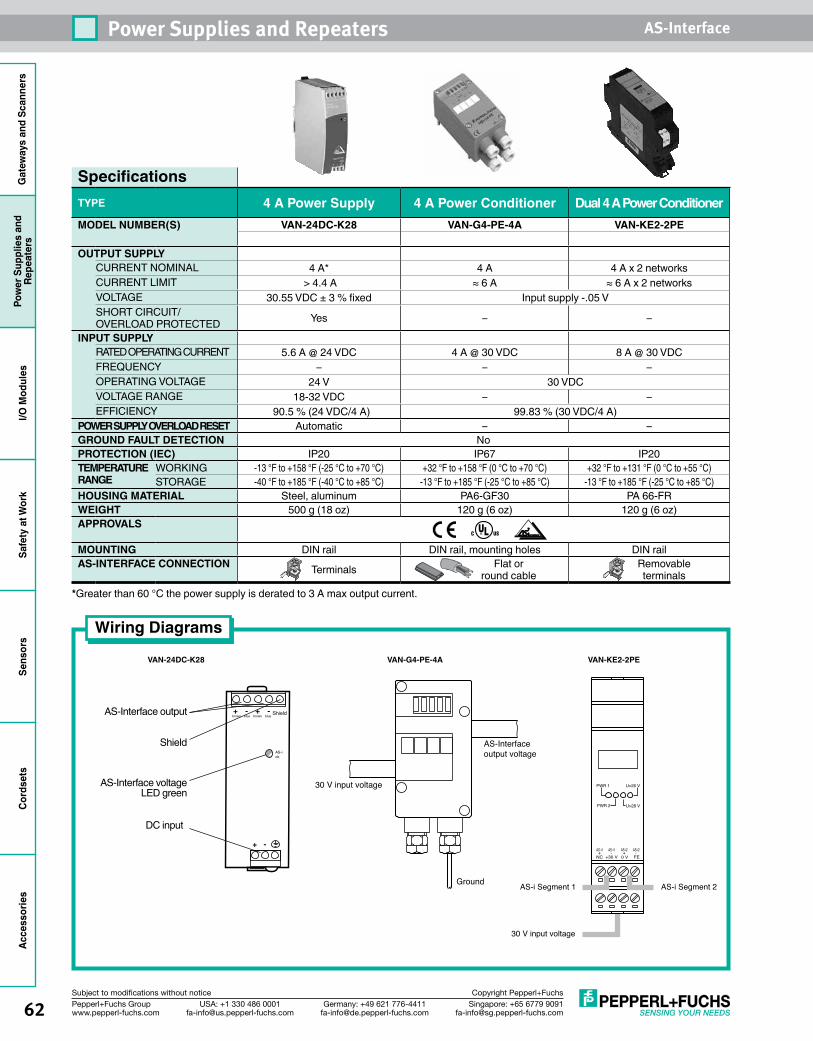
62 Singapore: +65 6779 [email protected]
USA: +1 330 486 [email protected]
Germany: +49 621 [email protected]
Pepperl+Fuchs Groupwww.pepperl-fuchs.com
Subject to modifications without notice Copyright Pepperl+Fuchs
Power Supplies and Repeaters AS-InterfaceG
atew
ays
and
Scan
ners
Pow
er S
uppl
ies
and
Repe
ater
sI/O
Mod
ules
Safe
ty a
t Wor
kSe
nsor
sCo
rdse
tsAc
cess
orie
s
SpecificationsTYPE 4 A Power Supply 4 A Power Conditioner Dual 4 A Power ConditionerMODEL NUMBER(S) VAN-24DC-K28 VAN-G4-PE-4A VAN-KE2-2PE
OUTPUT SUPPLYCURRENT NOMINAL 4 A* 4 A 4 A x 2 networksCURRENT LIMIT > 4.4 A ≈ 6 A ≈ 6 A x 2 networksVOLTAGE 30.55 VDC ± 3 % fixed Input supply -.05 VSHORT CIRCUIT/ OVERLOAD PROTECTED Yes – –
INPUT SUPPLYRATED OPERATING CURRENT 5.6 A @ 24 VDC 4 A @ 30 VDC 8 A @ 30 VDCFREQUENCY – – –OPERATING VOLTAGE 24 V 30 VDCVOLTAGE RANGE 18-32 VDC – –EFFICIENCY 90.5 % (24 VDC/4 A) 99.83 % (30 VDC/4 A)
POWER SUPPLY OVERLOAD RESET Automatic – –GROUND FAULT DETECTION NoPROTECTION (IEC) IP20 IP67 IP20TEMPERATURE RANGE
WORKING -13 °F to +158 °F (-25 °C to +70 °C) +32 °F to +158 °F (0 °C to +70 °C) +32 °F to +131 °F (0 °C to +55 °C)STORAGE -40 °F to +185 °F (-40 °C to +85 °C) -13 °F to +185 °F (-25 °C to +85 °C) -13 °F to +185 °F (-25 °C to +85 °C)
HOUSING MATERIAL Steel, aluminum PA6-GF30 PA 66-FRWEIGHT 500 g (18 oz) 120 g (6 oz) 120 g (6 oz)APPROVALS
MOUNTING DIN rail DIN rail, mounting holes DIN railAS-INTERFACE CONNECTION Terminals Flat or
round cableRemovable terminals
*Greater than 60 °C the power supply is derated to 3 A max output current.
VAN-24DC-K28 VAN-G4-PE-4A VAN-KE2-2PE
AS-Interfaceoutput voltage
30 V input voltage
Ground
DC input
AS-Interface voltage LED green
AS-Interface output
Shield
+ -
+ - + - Shieldbrown bluebrownblue
AS-iok
Wiring Diagrams
AS-i2 AS-i2-+-+
FE0 V+30 VNCAS-i1AS-i1
PWR 1
PWR 2
U>26 V
U>28 V
30 V input voltage
AS-i Segment 1 AS-i Segment 2
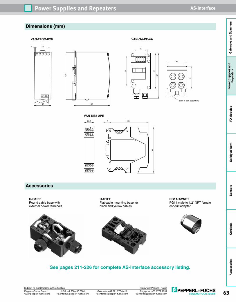
63Singapore: +65 6779 [email protected]
USA: +1 330 486 [email protected]
Germany: +49 621 [email protected]
Pepperl+Fuchs Groupwww.pepperl-fuchs.com
Subject to modifications without notice Copyright Pepperl+Fuchs
Power Supplies and Repeaters AS-Interface
Gat
eway
s an
d Sc
anne
rsPo
wer
Sup
plie
s an
d Re
peat
ers
I/O M
odul
esSa
fety
at W
ork
Sens
ors
Cord
sets
Acce
ssor
ies
Dimensions (mm)
VAN-24DC-K28 VAN-G4-PE-4A
4015.7 19.1
324
124
102Base is sold separately
31
66 8010
2
51
45
Accessories
U-G1FFFlat cable mounting base for black and yellow cables
U-G1PPRound cable base with external power terminals
PG11-1/2NPTPG11 male to 1/2" NPT female conduit adapter
See pages 211-226 for complete AS-Interface accessory listing.
VAN-KE2-2PE22.5 857
99
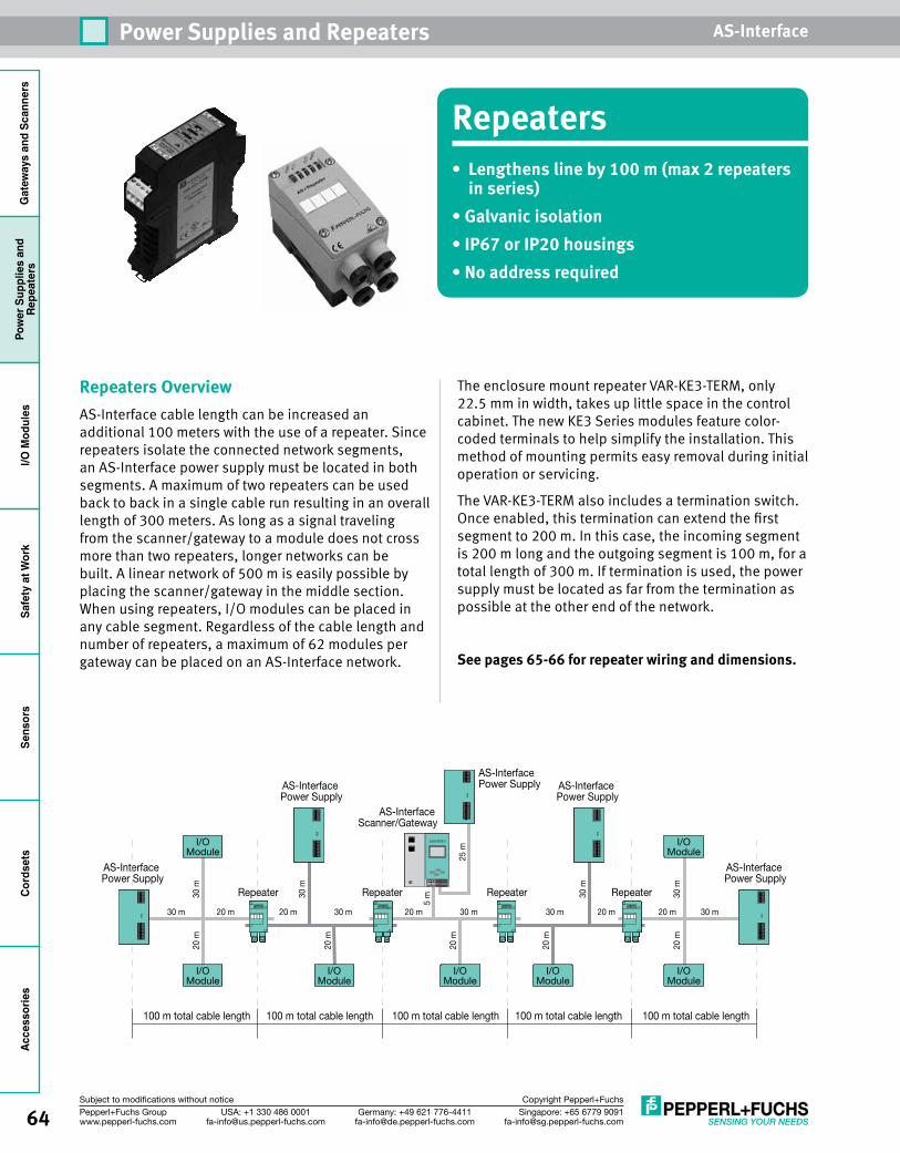
64 Singapore: +65 6779 [email protected]
USA: +1 330 486 [email protected]
Germany: +49 621 [email protected]
Pepperl+Fuchs Groupwww.pepperl-fuchs.com
Subject to modifications without notice Copyright Pepperl+Fuchs
Power Supplies and Repeaters AS-InterfaceG
atew
ays
and
Scan
ners
Pow
er S
uppl
ies
and
Repe
ater
sI/O
Mod
ules
Safe
ty a
t Wor
kSe
nsor
sCo
rdse
tsAc
cess
orie
s
Repeaters• Lengthens line by 100 m (max 2 repeaters
in series)• Galvanic isolation • IP67 or IP20 housings • No address required
Repeaters OverviewAS-Interface cable length can be increased an additional 100 meters with the use of a repeater. Since repeaters isolate the connected network segments, an AS-Interface power supply must be located in both segments. A maximum of two repeaters can be used back to back in a single cable run resulting in an overall length of 300 meters. As long as a signal traveling from the scanner/gateway to a module does not cross more than two repeaters, longer networks can be built. A linear network of 500 m is easily possible by placing the scanner/gateway in the middle section. When using repeaters, I/O modules can be placed in any cable segment. Regardless of the cable length and number of repeaters, a maximum of 62 modules per gateway can be placed on an AS-Interface network.
The enclosure mount repeater VAR-KE3-TERM, only 22.5 mm in width, takes up little space in the control cabinet. The new KE3 Series modules feature color-coded terminals to help simplify the installation. This method of mounting permits easy removal during initial operation or servicing.
The VAR-KE3-TERM also includes a termination switch. Once enabled, this termination can extend the first segment to 200 m. In this case, the incoming segment is 200 m long and the outgoing segment is 100 m, for a total length of 300 m. If termination is used, the power supply must be located as far from the termination as possible at the other end of the network.
See pages 65-66 for repeater wiring and dimensions.
I/OModule
I/OModule
I/OModule
I/OModule
I/OModule
I/OModule
I/OModule
AS-Interface Power Supply
AS-Interface Power Supply AS-Interface
Power SupplyAS-Interface Power Supply
AS-Interface Power Supply
AS-Interface Scanner/Gateway
30 m 30 m
30 m
30 m
30 m
5 m
20 m
30 m
20 m
20 m
20 m
20 m
25 m
20 m 20 m20 m 20 m30 m 30 m20 m 30 m
100 m total cable length100 m total cable length 100 m total cable length 100 m total cable length 100 m total cable length
Repeater Repeater Repeater Repeater
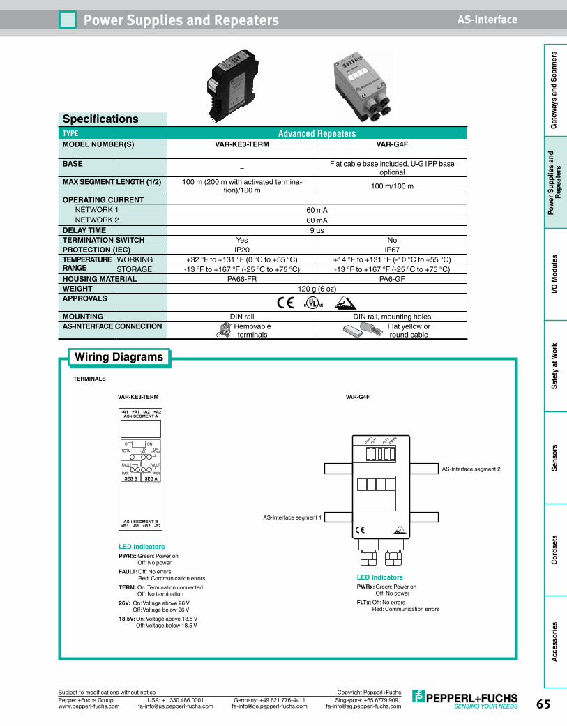
65Singapore: +65 6779 [email protected]
USA: +1 330 486 [email protected]
Germany: +49 621 [email protected]
Pepperl+Fuchs Groupwww.pepperl-fuchs.com
Subject to modifications without notice Copyright Pepperl+Fuchs
Power Supplies and Repeaters AS-Interface
Gat
eway
s an
d Sc
anne
rsPo
wer
Sup
plie
s an
d Re
peat
ers
I/O M
odul
esSa
fety
at W
ork
Sens
ors
Cord
sets
Acce
ssor
ies
SpecificationsTYPE Advanced RepeatersMODEL NUMBER(S) VAR-KE3-TERM VAR-G4F
BASE – Flat cable base included, U-G1PP base optional
MAX SEGMENT LENGTH (1/2) 100 m (200 m with activated termina-tion)/100 m 100 m/100 m
OPERATING CURRENTNETWORK 1 60 mANETWORK 2 60 mA
DELAY TIME 9 µs TERMINATION SWITCH Yes NoPROTECTION (IEC) IP20 IP67TEMPERATURE RANGE
WORKING +32 °F to +131 °F (0 °C to +55 °C) +14 °F to +131 °F (-10 °C to +55 °C)STORAGE -13 °F to +167 °F (-25 °C to +75 °C) -13 °F to +167 °F (-25 °C to +75 °C)
HOUSING MATERIAL PA66-FR PA6-GFWEIGHT 120 g (6 oz)APPROVALS
MOUNTING DIN rail DIN rail, mounting holesAS-INTERFACE CONNECTION Removable
terminalsFlat yellow or round cable
VAR-KE3-TERM VAR-G4F
AS-Interface segment 1
AS-Interface segment 2
PWR1FLT
1PWR2
FLT2
Wiring Diagrams
TERMINALS
LED IndicatorsPWRx: Green: Power on
Off: No powerFAULT: Off: No errors
Red: Communication errorsTERM: On: Termination connected
Off: No termination26V: On: Voltage above 26 V
Off: Voltage below 26 V18.5V: On: Voltage above 18.5 V
Off: Voltage below 18.5 V
LED IndicatorsPWRx: Green: Power on
Off: No powerFLTx: Off: No errors
Red: Communication errors
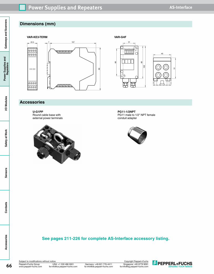
66 Singapore: +65 6779 [email protected]
USA: +1 330 486 [email protected]
Germany: +49 621 [email protected]
Pepperl+Fuchs Groupwww.pepperl-fuchs.com
Subject to modifications without notice Copyright Pepperl+Fuchs
Power Supplies and Repeaters AS-InterfaceG
atew
ays
and
Scan
ners
Pow
er S
uppl
ies
and
Repe
ater
sI/O
Mod
ules
Safe
ty a
t Wor
kSe
nsor
sCo
rdse
tsAc
cess
orie
s
Dimensions (mm)
VAR-KE3-TERM VAR-G4F31
66 8010
2
51
45
Accessories
U-G1PPRound cable base with external power terminals
PG11-1/2NPTPG11 male to 1/2" NPT female conduit adapter
See pages 211-226 for complete AS-Interface accessory listing.
22.5 7 107
99
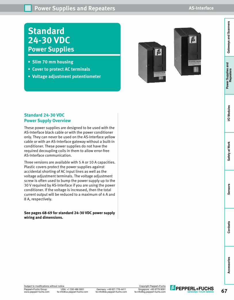
67Singapore: +65 6779 [email protected]
USA: +1 330 486 [email protected]
Germany: +49 621 [email protected]
Pepperl+Fuchs Groupwww.pepperl-fuchs.com
Subject to modifications without notice Copyright Pepperl+Fuchs
Power Supplies and Repeaters AS-Interface
Gat
eway
s an
d Sc
anne
rsPo
wer
Sup
plie
s an
d Re
peat
ers
I/O M
odul
esSa
fety
at W
ork
Sens
ors
Cord
sets
Acce
ssor
ies
Standard 24-30 VDCPower Supplies • Slim 70 mm housing• Cover to protect AC terminals• Voltage adjustment potentiometer
Standard 24-30 VDC Power Supply OverviewThese power supplies are designed to be used with the AS-Interface black cable or with the power conditioner only. They can never be used on the AS-Interface yellow cable or with an AS-Interface gateway without a built-in conditioner. These power supplies do not have the required decoupling coils in them to allow error-free AS-Interface communication.
Three versions are available with 5 A or 10 A capacities. Plastic covers protect the power supplies against accidental shorting of AC input lines as well as the voltage adjustment terminals. The voltage adjustment screw is often used to bump the power supply up to the 30 V required by AS-Interface if you are using the power conditioner. If the voltage is increased, then the total current output will be reduced to a maximum of 4 A and 8 A, respectively.
See pages 68-69 for standard 24-30 VDC power supply wiring and dimensions.
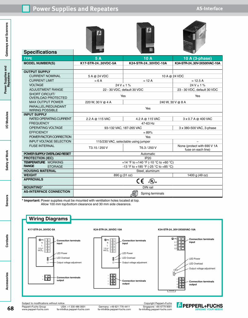
68 Singapore: +65 6779 [email protected]
USA: +1 330 486 [email protected]
Germany: +49 621 [email protected]
Pepperl+Fuchs Groupwww.pepperl-fuchs.com
Subject to modifications without notice Copyright Pepperl+Fuchs
Power Supplies and Repeaters AS-InterfaceG
atew
ays
and
Scan
ners
Pow
er S
uppl
ies
and
Repe
ater
sI/O
Mod
ules
Safe
ty a
t Wor
kSe
nsor
sCo
rdse
tsAc
cess
orie
s
SpecificationsTYPE 5 A 10 A 10 A (3-phase)MODEL NUMBER(S) K17-STR-24..30VDC-5A K24-STR-24..30VDC-10A K34-STR-24..30V-3X500VAC-10A
OUTPUT SUPPLYCURRENT NOMINAL 5 A @ 24 VDC 10 A @ 24 VDCCURRENT LIMIT ≈ 6 A ≈ 12 A ≈ 12.5 AVOLTAGE 24 V ± 1 % 24 V ± 1 %ADJUSTMENT RANGE 22 - 30 VDC, default 30 VDC 23 - 30 VDC, default 30 VDCSHORT CIRCUIT/ OVERLOAD PROTECTED Yes Yes
MAX OUTPUT POWER 220 W, 30 V @ 4 A 240 W, 30 V @ 8 APARALLEL/REDUNDANT WIRING POSSIBLE Yes
INPUT SUPPLYRATED OPERATING CURRENT 2.2 A @ 115 VAC 4.2 A @ 115 VAC 3 x 0.7 A @ 400 VACFREQUENCY 47-63 HzOPERATING VOLTAGE 93-132 VAC, 187-265 VAC 3 x 380-500 VAC, 3-phaseEFFICIENCY ≈ 89%POWER FACTOR CORRECTION YesINPUT VOLTAGE SELECTION 115/230 VAC, selectable using jumper –FUSE INTERNAL T3.15 / 250 V T6.3 / 250 V None (protect with 690 V 1A
fuse on each line)POWER SUPPLY OVERLOAD RESET AutomaticPROTECTION (IEC) IP20TEMPERATURE RANGE
WORKING +14 °F to +140 °F (-10 °C to +60 °C)STORAGE -13 °F to +185 °F (-25 °C to +85 °C)
HOUSING MATERIAL Steel, aluminumWEIGHT 890 g (31 oz) 1400 g (49 oz)APPROVALS
MOUNTING* DIN railAS-INTERFACE CONNECTION Spring terminals
* Important: Power supplies must be mounted with ventilation holes located at top. Allow 100 mm top/bottom clearance and 30 mm side clearance.
Wiring Diagrams
K24-STR-24..30VDC-10A K34-STR-24..30V-3X500VAC-10A
LED Power
LED Overload
Output voltage adjustment
PE
NL
115VAC
++––
Connection terminalsinput
Connection terminals output
K17-STR-24..30VDC-5A
LED Power
LED Overload
Output voltage adjustment
PE
NL
115VAC
+
–
Connection terminalsinput
Connection terminals output
LED Power
LED Overload
Output voltage adjustment
PE
L1
L2
L3
Connection terminalsinput
Connection terminals output
+
-
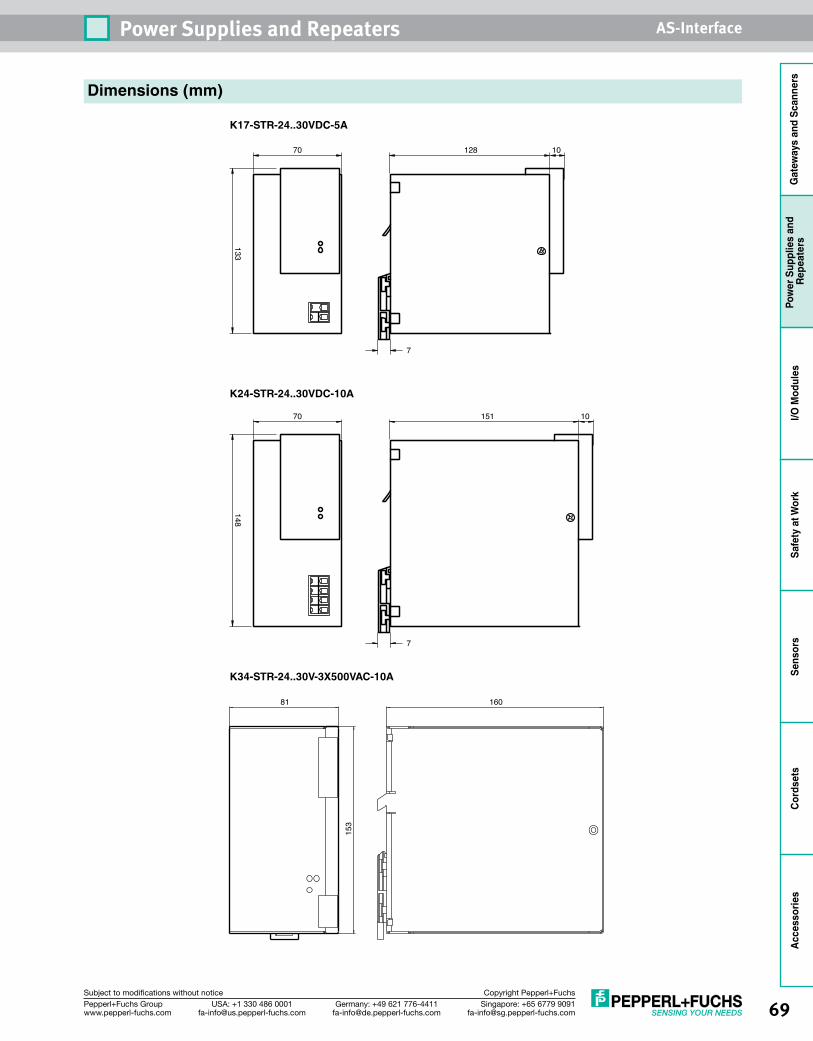
69Singapore: +65 6779 [email protected]
USA: +1 330 486 [email protected]
Germany: +49 621 [email protected]
Pepperl+Fuchs Groupwww.pepperl-fuchs.com
Subject to modifications without notice Copyright Pepperl+Fuchs
Power Supplies and Repeaters AS-Interface
Gat
eway
s an
d Sc
anne
rsPo
wer
Sup
plie
s an
d Re
peat
ers
I/O M
odul
esSa
fety
at W
ork
Sens
ors
Cord
sets
Acce
ssor
ies
K24-STR-24..30VDC-10A
K34-STR-24..30V-3X500VAC-10A
148
70 151 10
7
Dimensions (mm)
K17-STR-24..30VDC-5A
133
70 128 10
7
81
153
160
70 Singapore: +65 6779 [email protected]
USA: +1 330 486 [email protected]
Germany: +49 621 [email protected]
Pepperl+Fuchs Groupwww.pepperl-fuchs.com
Subject to modifications without notice Copyright Pepperl+Fuchs
Power Supplies and Repeaters AS-InterfaceG
atew
ays
and
Scan
ners
Pow
er S
uppl
ies
and
Repe
ater
sI/O
Mod
ules
Safe
ty a
t Wor
kSe
nsor
sCo
rdse
tsAc
cess
orie
s
Notes
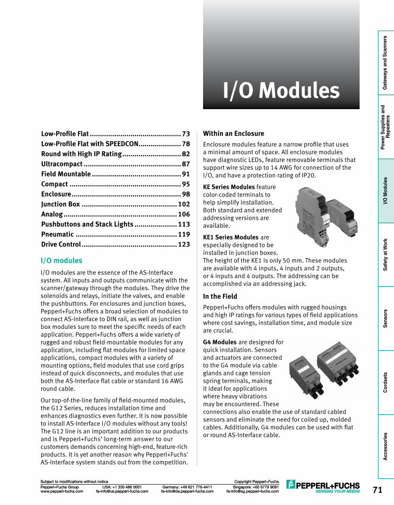
71Singapore: +65 6779 [email protected]
USA: +1 330 486 [email protected]
Germany: +49 621 [email protected]
Pepperl+Fuchs Groupwww.pepperl-fuchs.com
Subject to modifications without notice Copyright Pepperl+Fuchs
I/O Modules
Gat
eway
s an
d Sc
anne
rsPo
wer
Sup
plie
s an
d Re
peat
ers
I/O M
odul
esSa
fety
at W
ork
Sens
ors
Cord
sets
Acce
ssor
ies
Singapore: +65 6779 [email protected]
USA: +1 330 486 [email protected]
Germany: +49 621 [email protected]
Pepperl+Fuchs Groupwww.pepperl-fuchs.com
Subject to modifications without notice Copyright Pepperl+Fuchs
I/O Modules
I/O modulesI/O modules are the essence of the AS-Interface system. All inputs and outputs communicate with the scanner/gateway through the modules. They drive the solenoids and relays, initiate the valves, and enable the pushbuttons. For enclosures and junction boxes, Pepperl+Fuchs offers a broad selection of modules to connect AS-Interface to DIN rail, as well as junction box modules sure to meet the specific needs of each application. Pepperl+Fuchs offers a wide variety of rugged and robust field-mountable modules for any application, including flat modules for limited space applications, compact modules with a variety of mounting options, field modules that use cord grips instead of quick disconnects, and modules that use both the AS-Interface flat cable or standard 16 AWG round cable.
Our top-of-the-line family of field-mounted modules, the G12 Series, reduces installation time and enhances diagnostics even further. It is now possible to install AS-Interface I/O modules without any tools! The G12 line is an important addition to our products and is Pepperl+Fuchs’ long-term answer to our customers demands concerning high-end, feature-rich products. It is yet another reason why Pepperl+Fuchs' AS-Interface system stands out from the competition.
Within an EnclosureEnclosure modules feature a narrow profile that uses a minimal amount of space. All enclosure modules have diagnostic LEDs, feature removable terminals that support wire sizes up to 14 AWG for connection of the I/O, and have a protection rating of IP20.
KE Series Modules feature color-coded terminals to help simplify installation. Both standard and extended addressing versions are available.
KE1 Series Modules are especially designed to be installed in junction boxes. The height of the KE1 is only 50 mm. These modules are available with 4 inputs, 4 inputs and 2 outputs, or 4 inputs and 4 outputs. The addressing can be accomplished via an addressing jack.
In the FieldPepperl+Fuchs offers modules with rugged housings and high IP ratings for various types of field applications where cost savings, installation time, and module size are crucial.
G4 Modules are designed for quick installation. Sensors and actuators are connected to the G4 module via cable glands and cage tension spring terminals, making it ideal for applications where heavy vibrations may be encountered. These connections also enable the use of standard cabled sensors and eliminate the need for coiled up, molded cables. Additionally, G4 modules can be used with flat or round AS-Interface cable.
Low-Profile Flat ............................................. 73Low-Profile Flat with SPEEDCON ..................... 78Round with High IP Rating ............................. 82Ultracompact ................................................ 87Field Mountable ............................................ 91Compact ....................................................... 95Enclosure ...................................................... 98Junction Box ............................................... 102Analog ........................................................ 106Pushbuttons and Stack Lights ..................... 113Pneumatic .................................................. 119Drive Control ............................................... 123
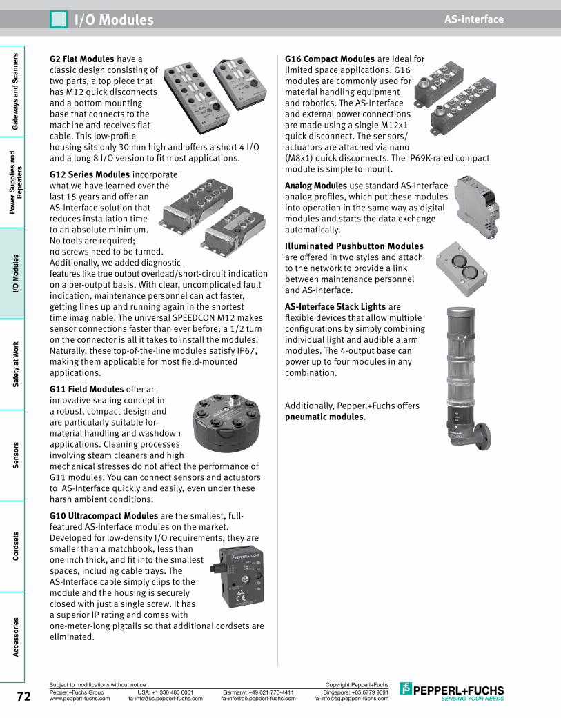
Gat
eway
s an
d Sc
anne
rsPo
wer
Sup
plie
s an
dRe
peat
ers
I/O M
odul
esSa
fety
at W
ork
Sens
ors
Cord
sets
Acce
ssor
ies
72 Singapore: +65 6779 [email protected]
USA: +1 330 486 [email protected]
Germany: +49 621 [email protected]
Pepperl+Fuchs Groupwww.pepperl-fuchs.com
Subject to modifications without notice Copyright Pepperl+Fuchs
I/O Modules AS-Interface
G2 Flat Modules have a classic design consisting of two parts, a top piece that has M12 quick disconnects and a bottom mounting base that connects to the machine and receives flat cable. This low-profile housing sits only 30 mm high and offers a short 4 I/O and a long 8 I/O version to fit most applications.
G12 Series Modules incorporate what we have learned over the last 15 years and offer an AS-Interface solution that reduces installation time to an absolute minimum. No tools are required; no screws need to be turned. Additionally, we added diagnostic features like true output overload/short-circuit indication on a per-output basis. With clear, uncomplicated fault indication, maintenance personnel can act faster, getting lines up and running again in the shortest time imaginable. The universal SPEEDCON M12 makes sensor connections faster than ever before; a 1/2 turn on the connector is all it takes to install the modules. Naturally, these top-of-the-line modules satisfy IP67, making them applicable for most field-mounted applications.
G11 Field Modules offer an innovative sealing concept in a robust, compact design and are particularly suitable for material handling and washdown applications. Cleaning processes involving steam cleaners and high mechanical stresses do not affect the performance of G11 modules. You can connect sensors and actuators to AS-Interface quickly and easily, even under these harsh ambient conditions.
G10 Ultracompact Modules are the smallest, full-featured AS-Interface modules on the market. Developed for low-density I/O requirements, they are smaller than a matchbook, less than one inch thick, and fit into the smallest spaces, including cable trays. The AS-Interface cable simply clips to the module and the housing is securely closed with just a single screw. It has a superior IP rating and comes with one-meter-long pigtails so that additional cordsets are eliminated.
G16 Compact Modules are ideal for limited space applications. G16 modules are commonly used for material handling equipment and robotics. The AS-Interface and external power connections are made using a single M12x1 quick disconnect. The sensors/actuators are attached via nano (M8x1) quick disconnects. The IP69K-rated compact module is simple to mount.
Analog Modules use standard AS-Interface analog profiles, which put these modules into operation in the same way as digital modules and starts the data exchange automatically.
Illuminated Pushbutton Modules are offered in two styles and attach to the network to provide a link between maintenance personnel and AS-Interface.
AS-Interface Stack Lights are flexible devices that allow multiple configurations by simply combining individual light and audible alarm modules. The 4-output base can power up to four modules in any combination.
Additionally, Pepperl+Fuchs offers pneumatic modules.
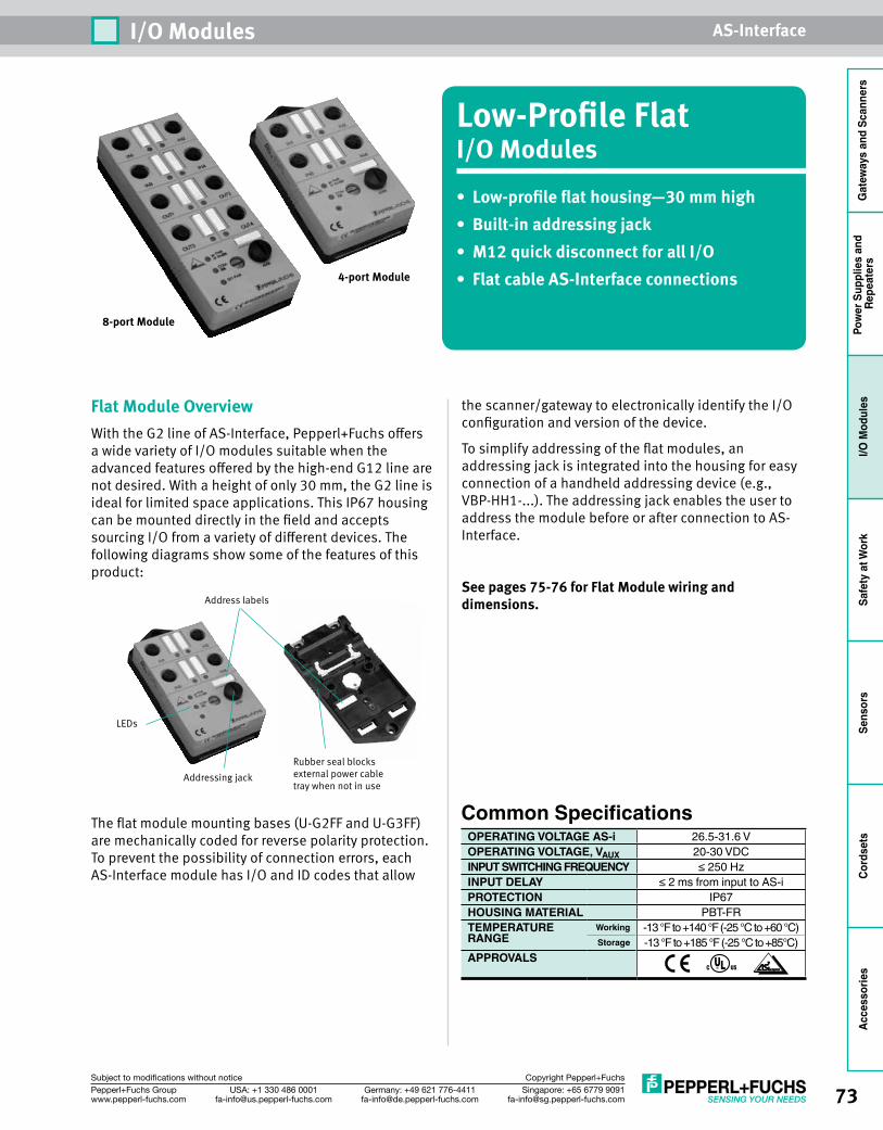
73Singapore: +65 6779 [email protected]
USA: +1 330 486 [email protected]
Germany: +49 621 [email protected]
Pepperl+Fuchs Groupwww.pepperl-fuchs.com
Subject to modifications without notice Copyright Pepperl+Fuchs
I/O Modules AS-Interface
Gat
eway
s an
d Sc
anne
rsPo
wer
Sup
plie
s an
d Re
peat
ers
I/O M
odul
esSa
fety
at W
ork
Sens
ors
Cord
sets
Acce
ssor
ies
the scanner/gateway to electronically identify the I/O configuration and version of the device.
To simplify addressing of the flat modules, an addressing jack is integrated into the housing for easy connection of a handheld addressing device (e.g., VBP-HH1-...). The addressing jack enables the user to address the module before or after connection to AS-Interface.
See pages 75-76 for Flat Module wiring and dimensions.
Low-Profile FlatI/O Modules• Low-profile flat housing—30 mm high• Built-in addressing jack• M12 quick disconnect for all I/O• Flat cable AS-Interface connections
8-port Module
4-port Module
Flat Module OverviewWith the G2 line of AS-Interface, Pepperl+Fuchs offers a wide variety of I/O modules suitable when the advanced features offered by the high-end G12 line are not desired. With a height of only 30 mm, the G2 line is ideal for limited space applications. This IP67 housing can be mounted directly in the field and accepts sourcing I/O from a variety of different devices. The following diagrams show some of the features of this product:
The flat module mounting bases (U-G2FF and U-G3FF) are mechanically coded for reverse polarity protection. To prevent the possibility of connection errors, each AS-Interface module has I/O and ID codes that allow
Common SpecificationsOPERATING VOLTAGE AS-i 26.5-31.6 VOPERATING VOLTAGE, VAUX 20-30 VDCINPUT SWITCHING FREQUENCY ≤ 250 HzINPUT DELAY ≤ 2 ms from input to AS-iPROTECTION IP67HOUSING MATERIAL PBT-FRTEMPERATURE Working -13 °F to +140 °F (-25 °C to +60 °C)RANGE Storage -13 °F to +185 °F (-25 °C to +85°C)APPROVALS
Address labels
LEDs
Addressing jackRubber seal blocks external power cable tray when not in use
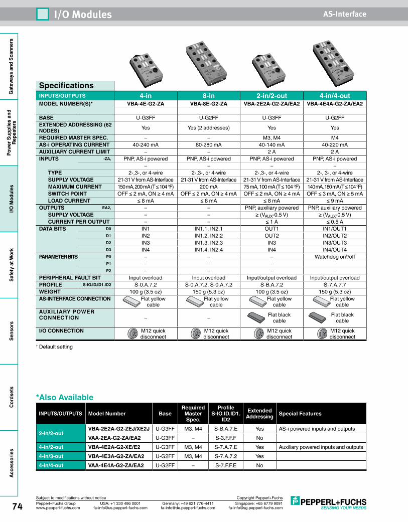
Gat
eway
s an
d Sc
anne
rsPo
wer
Sup
plie
s an
dRe
peat
ers
I/O M
odul
esSa
fety
at W
ork
Sens
ors
Cord
sets
Acce
ssor
ies
74 Singapore: +65 6779 [email protected]
USA: +1 330 486 [email protected]
Germany: +49 621 [email protected]
Pepperl+Fuchs Groupwww.pepperl-fuchs.com
Subject to modifications without notice Copyright Pepperl+Fuchs
I/O Modules AS-Interface
SpecificationsINPUTS/OUTPUTS 4-in 8-in 2-in/2-out 4-in/4-outMODEL NUMBER(S)* VBA-4E-G2-ZA VBA-8E-G2-ZA VBA-2E2A-G2-ZA/EA2 VBA-4E4A-G2-ZA/EA2
BASE U-G3FF U-G2FF U-G3FF U-G2FFEXTENDED ADDRESSING (62 NODES) Yes Yes (2 addresses) Yes Yes
REQUIRED MASTER SPEC. – – M3, M4 M4AS-i OPERATING CURRENT 40-240 mA 80-280 mA 40-140 mA 40-220 mAAUXILIARY CURRENT LIMIT – – 2 A 2 AINPUTS -ZA, PNP, AS-i powered PNP, AS-i powered PNP, AS-i powered PNP, AS-i powered
– – – –TYPE 2-,3-, or 4-wire 2-,3-, or 4-wire 2-,3-, or 4-wire 2-, 3-, or 4-wireSUPPLY VOLTAGE 21-31 V from AS-Interface 21-31 V from AS-Interface 21-31 V from AS-Interface 21-31 V from AS-InterfaceMAXIMUM CURRENT 150 mA, 200 mA (T ≤ 104 °F) 200 mA 75 mA, 100 mA (T ≤ 104 °F) 140 mA, 180 mA (T ≤ 104 °F)SWITCH POINT OFF ≤ 2 mA, ON ≥ 4 mA OFF ≤ 2 mA, ON ≥ 4 mA OFF ≤ 2 mA, ON ≥ 4 mA OFF ≤ 3 mA, ON ≥ 5 mALOAD CURRENT ≤ 8 mA ≤ 8 mA ≤ 8 mA ≤ 9 mA
OUTPUTS EA2, – – PNP, auxiliary powered PNP, auxiliary poweredSUPPLY VOLTAGE – – ≥ (VAUX-0.5 V) ≥ (VAUX-0.5 V)CURRENT PER OUTPUT – – ≤ 1 A ≤ 0.5 A
DATA BITS D0 IN1 IN1.1, IN2.1 OUT1 IN1/OUT1D1 IN2 IN1.2, IN2.2 OUT2 IN2/OUT2D2 IN3 IN1.3, IN2.3 IN3 IN3/OUT3D3 IN4 IN1.4, IN2.4 IN4 IN4/OUT4
PARAMETER BITS P0 – – – Watchdog on†/offP1 – – – –P2 – – – –
PERIPHERAL FAULT BIT Input overload Input overload Input/output overload Input/output overloadPROFILE S-IO.ID.ID1.ID2 S-0.A.7.2 S-0.A.7.2, S-0.A.7.2 S-B.A.7.2 S-7.A.7.7WEIGHT 100 g (3.5 oz) 150 g (5.3 oz) 100 g (3.5 oz) 150 g (5.3 oz)AS-INTERFACE CONNECTION Flat yellow
cableFlat yellow
cableFlat yellow
cableFlat yellow
cableAUXILIARY POWER CONNECTION – – Flat black
cableFlat black
cable
I/O CONNECTION M12 quick disconnect
M12 quick disconnect
M12 quick disconnect
M12 quick disconnect
† Default setting
*Also Available
INPUTS/OUTPUTS Model Number BaseRequired
Master Spec.
Profile S-IO.ID.ID1.
ID2Extended
Addressing Special Features
2-in/2-outVBA-2E2A-G2-ZEJ/XE2J U-G3FF M3, M4 S-B.A.7.E Yes AS-i powered inputs and outputsVAA-2EA-G2-ZA/EA2 U-G3FF – S-3.F.F.F No
4-in/2-out VBA-4E2A-G2-XE/E2 U-G3FF M3, M4 S-7.A.7.E Yes Auxiliary powered inputs and outputs4-in/3-out VBA-4E3A-G2-ZA/EA2 U-G2FF M3, M4 S-7.A.7.2 Yes4-in/4-out VAA-4E4A-G2-ZA/EA2 U-G2FF – S-7.F.F.E No
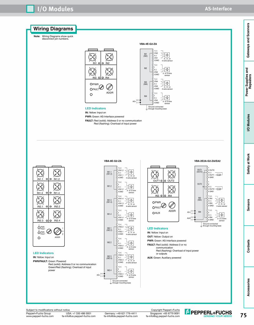
75Singapore: +65 6779 [email protected]
USA: +1 330 486 [email protected]
Germany: +49 621 [email protected]
Pepperl+Fuchs Groupwww.pepperl-fuchs.com
Subject to modifications without notice Copyright Pepperl+Fuchs
I/O Modules AS-Interface
Gat
eway
s an
d Sc
anne
rsPo
wer
Sup
plie
s an
d Re
peat
ers
I/O M
odul
esSa
fety
at W
ork
Sens
ors
Cord
sets
Acce
ssor
ies
Note: Wiring Diagrams show quick disconnect pin numbers.
Wiring Diagrams
1 (+)2 IN1.23 (-)4 IN1.15 GND
1 (+)2
2-, 3-, or4-wire sensor
3 (-)4 IN1.25 GND
1 (+)2 IN1.4 3 (-)4 IN1.35 GND
1 (+)2 3 (-)4 IN1.45 GND
Ground connectedthrough mounting base
2-, 3-, or4-wire sensor
2- or 3-wiresensor
2- or 3-wiresensor
1 (+)2 IN2.23 (-)4 IN2.15 GND
1 (+)2
2-, 3-, or4-wire sensor
3 (-)4 IN2.25 GND
1 (+)2 IN2.4 3 (-)4 IN2.35 GND
1 (+)2 3 (-)4 IN2.45 GND
2-, 3-, or4-wire sensor
2- or 3-wiresensor
2- or 3-wiresensor
IN1.1(IN1.2)
IN1.2
IN1.3(IN1.4)
IN1.4
IN2.1(IN2.2)
IN2.2
IN2.3(IN2.4)
IN2.4
(+)(-)AS-i
VBA-8E-G2-ZA
4
3
1
2
5
4
3
1
2
5
ADDR
2 1
3 4
5
2 1
3 4
5
4
3
1
2
5
4
3
1
2
5
5
2 1
3 4
2 1
3 4
5
FAULT
FAULTPWR/
PWR/1
2
IN1.1
IN1.3
IN2.1
IN2.3
IN1.2
IN1.4
IN2.2
IN2.4
1
2
1 (+)2 IN23 (-)4 IN15 GND
1 (+)2
2-, 3-, or4-wire sensor
3 (-)4 IN25 GND
1 (+)2 IN4 3 (-)4 IN35 GND
1 (+)2 3 (-)4 IN45 GND
2-, 3-, or4-wire sensor
2- or 3-wiresensor
2- or 3-wiresensor
IN1(IN2)
IN2
IN3(IN4)
IN4
(+)(-)AS-i
Ground connectedthrough mounting base
VBA-4E-G2-ZA
4
3
1
2
5
4
3
1
2
5
IN1 IN2
IN3 IN4
PWR
FAULTADDR
5
2 1
3 4
2 1
3 4
5
1 (+)2 IN43 (-)4 IN35 GND
1 (+)2 3 (-)4 IN45 GND
12 OUT23 (-)4 OUT15 GND
1 2 3 (-)4 OUT25 GND
Load
Load
2- or 3-wiresensor
OUT1(OUT2)
OUT2
IN3(IN4)
IN4
2-, 3-, or4-wire sensor
(+)(-)
AUX
(+)(-)AS-i
Ground connectedthrough mounting base
VBA-2E2A-G2-ZA/EA2
4
3
1
2
5
4
3
1
2
5
OUT1 OUT2
IN3 IN4
PWR
FAULT
AUXADDR
5
2 1
3 4
2 1
3 4
5
LED IndicatorsIN: Yellow: Input onPWR: Green: AS-Interface poweredFAULT: Red (solid): Address 0 or no communication
Red (flashing): Overload of input power
LED IndicatorsIN: Yellow: Input onPWR/FAULT: Green: Powered
Red (solid): Address 0 or no communication Green/Red (flashing): Overload of input power
LED IndicatorsIN: Yellow: Input onOUT: Yellow: Output onPWR: Green: AS-Interface poweredFAULT: Red (solid): Address 0 or no
communication Red (flashing): Overload of input power or outputs
AUX: Green: Auxiliary powered
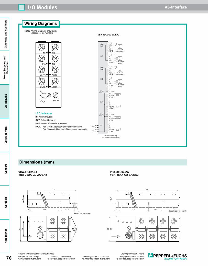
Gat
eway
s an
d Sc
anne
rsPo
wer
Sup
plie
s an
dRe
peat
ers
I/O M
odul
esSa
fety
at W
ork
Sens
ors
Cord
sets
Acce
ssor
ies
76 Singapore: +65 6779 [email protected]
USA: +1 330 486 [email protected]
Germany: +49 621 [email protected]
Pepperl+Fuchs Groupwww.pepperl-fuchs.com
Subject to modifications without notice Copyright Pepperl+Fuchs
I/O Modules AS-Interface
Note: Wiring Diagrams show quick disconnect pin numbers.
Wiring Diagrams
Dimensions (mm)
VBA-4E-G2-ZAVBA-2E2A-G2-ZA/EA2
VBA-8E-G2-ZAVBA-4E4A-G2-ZA/EA2
Base is sold separately
4 73.5 34.5
18.7
118
3660
Base is sold separately4 73.5 34.5
18.7
150
3660
1 (+)2 IN23 (-)4 IN15 GND
1 (+)2
2-, 3-, or4-wire sensor
3 (-)4 IN25 GND
1 (+)2 IN4 3 (-)4 IN35 GND
1 (+)2 3 (-)4 IN45 GND
2-, 3-, or4-wire sensor
2- or 3-wiresensor
2- or 3-wiresensor
IN1(IN2)
IN2
IN3(IN4)
IN4
OUT1(OUT2)
OUT2
OUT3(OUT4)
OUT4
12 OUT23 (-)4 OUT15 GND
1 2 3 (-)4 OUT25 GND
Load
Load
1 2 OUT4 3 (-)4 OUT35 GND
Load
1 2 3 (-)4 OUT45 GND
Load(+)(-)
AUX
(+)(-)
AS-i
Ground connectedthrough mounting base
VBA-4E4A-G2-ZA/EA2
4
3
1
2
5
4
3
1
2
5
PWR
FAULT
AUX ADDR
2 1
3 4
5
2 1
3 4
5
4
3
1
2
5
4
3
1
2
5
OUT3 OUT4
OUT1 OUT2
IN1 IN2
IN3 IN4
5
2 1
3 4
2 1
3 4
5
LED IndicatorsIN: Yellow: Input onOUT: Yellow: Output onPWR: Green: AS-Interface poweredFAULT: Red (solid): Address 0 or no communication
Red (flashing): Overload of input power or outputs
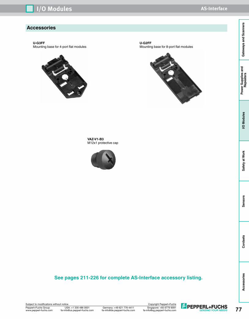
77Singapore: +65 6779 [email protected]
USA: +1 330 486 [email protected]
Germany: +49 621 [email protected]
Pepperl+Fuchs Groupwww.pepperl-fuchs.com
Subject to modifications without notice Copyright Pepperl+Fuchs
I/O Modules AS-Interface
Gat
eway
s an
d Sc
anne
rsPo
wer
Sup
plie
s an
d Re
peat
ers
I/O M
odul
esSa
fety
at W
ork
Sens
ors
Cord
sets
Acce
ssor
ies
Accessories
U-G3FFMounting base for 4-port flat modules
U-G2FFMounting base for 8-port flat modules
VAZ-V1-B3M12x1 protective cap
See pages 211-226 for complete AS-Interface accessory listing.

Gat
eway
s an
d Sc
anne
rsPo
wer
Sup
plie
s an
dRe
peat
ers
I/O M
odul
esSa
fety
at W
ork
Sens
ors
Cord
sets
Acce
ssor
ies
78 Singapore: +65 6779 [email protected]
USA: +1 330 486 [email protected]
Germany: +49 621 [email protected]
Pepperl+Fuchs Groupwww.pepperl-fuchs.com
Subject to modifications without notice Copyright Pepperl+Fuchs
I/O Modules AS-Interface
Low-Profile Flat with SPEEDCONI/O Modules• Low-profile flat housing—30 mm high• Standard and DIN rail mount integrated in
base• Built-in addressing jack• SPEEDCON M12 quick disconnect for all
I/O• Flat cable AS-Interface connections
Flat Module with SPEEDCON OverviewHigh-end G12 modules are ideal for applications requiring fast and flexible installation, easy access to diagnostic feedback, and long service lives. The G12 features a stainless steel installation bar that pulls the module safely onto the stainless steel base. Once the installation bar has been closed, a “click” tells the user that the module has been installed properly and securely. I/O connections are achieved with a single ½ turn using our SPEEDCON M12 solution. These M12 I/O connectors can be used with both standard cables as well as SPEEDCON versions.
G12 comes in a number of I/O mixes and two distinct housing sizes. Both housing sizes use the same rugged stainless steel mounting base. With the stainless steel mounting base, changing the I/O count is as simple as replacing one module top with another, without having to remount the base and AS-Interface cable.
Diagnostic feedback is provided with an output-specific overload indication right on the module. Under normal operating conditions, the multicolor LEDs display the state of the output. Short-circuited and overloaded outputs are provided at the PLC via the peripheral fault bit. This allows maintenance personnel to quickly determine which module has a problem. The overloaded output is directly indicated via a red LED. Faster problem resolution results in higher machine uptime.
Common SpecificationsOPERATING VOLTAGE AS-i 26.5-31.6 VOPERATING VOLTAGE, VAUX 20.4-27.6 VDCINPUT SWITCHING FREQUENCY ≤ 1 kHzINPUT DELAY ≤ 1 ms from input to AS-iPROTECTION IP67HOUSING MATERIAL PBTTEMPERATURE Working -13 °F to +158 °F (-25 °C to +70 °C)RANGE Storage -13 °F to +185 °F (-25 °C to +85 °C)APPROVALS
Gold-plated piercing contacts ensure long-term AS-Interface performance. Our machined, gold-plated contacts offer corrosion resistance that is superior to stamped (flat) contacts plated with nonprecious metals.
The G12 also features an integrated DIN clip for DIN rail mounting. With the integrated DIN clip, stainless steel mounting base customers do not have to choose ahead of time how G12 is mounted. Less to consider means faster planning, ordering, and installation.
See pages 80-81 for Flat Module with SPEEDCON wiring and dimensions.
8-port Module
4-port Module
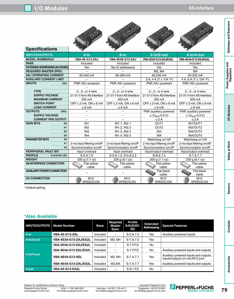
79Singapore: +65 6779 [email protected]
USA: +1 330 486 [email protected]
Germany: +49 621 [email protected]
Pepperl+Fuchs Groupwww.pepperl-fuchs.com
Subject to modifications without notice Copyright Pepperl+Fuchs
I/O Modules AS-Interface
Gat
eway
s an
d Sc
anne
rsPo
wer
Sup
plie
s an
d Re
peat
ers
I/O M
odul
esSa
fety
at W
ork
Sens
ors
Cord
sets
Acce
ssor
ies
SpecificationsINPUTS/OUTPUTS 4-in 8-in 2-in/2-out 4-in/4-outMODEL NUMBER(S)* VBA-4E-G12-ZAJ VBA-4E4E-G12-ZAJ VBA-2E2A-G12-ZAJ/EA2L VBA-4E4A-G12-ZAJ/EA2LBASE Included Included Included IncludedEXTENDED ADDRESSING (62 NODES) Yes Yes (2 addresses) Yes YesREQUIRED MASTER SPEC. – – M3, M4 M4AS-i OPERATING CURRENT 40-240 mA 80-280 mA 40-240 mA 40-240 mAAUXILIARY CURRENT LIMIT – – 3 A, 4 A (T ≤ 104 °F) 4 A, 6 A (T ≤ 104 °F)INPUTS -ZAJ PNP, AS-i powered PNP, AS-i powered PNP, AS-i powered PNP, AS-i powered
– – – –TYPE 2-, 3-, or 4-wire 2-, 3-, or 4-wire 2-, 3-, or 4-wire 2-, 3-, or 4-wireSUPPLY VOLTAGE 21-31 V from AS-Interface 21-31 V from AS-Interface 21-31 V from AS-Interface 21-31 V from AS-InterfaceMAXIMUM CURRENT 200 mA 200 mA 200 mA 200 mASWITCH POINT OFF ≤ 2 mA, ON ≥ 6 mA OFF ≤ 2 mA, ON ≥ 6 mA OFF ≤ 2 mA, ON ≥ 6 mA OFF ≤ 2 mA, ON ≥ 6 mALOAD CURRENT ≤ 8 mA ≤ 8 mA ≤ 8 mA ≤ 8 mA
OUTPUTS EA2L – – PNP, auxiliary powered PNP, auxiliary poweredSUPPLY VOLTAGE – – ≥ (VAUX-0.5 V) ≥ (VAUX-0.5 V)CURRENT PER OUTPUT – – ≤ 2 A ≤ 2 A
DATA BITS D0 IN1 IN1.1, IN2.1 OUT1 IN1/OUT1D1 IN2 IN1.2, IN2.2 OUT2 IN2/OUT2D2 IN3 IN1.3, IN2.3 IN3 IN3/OUT3D3 IN4 IN1.4, IN2.4 IN4 IN4/OUT4
PARAMETER BITS P0 – – Watchdog on†/off Watchdog on†/offP1 2 ms input filtering on/off† 2 ms input filtering on/off† 2 ms input filtering on/off† 2 ms input filtering on/off†
P2 Synchronization on/off† Synchronization on/off† Synchronization on/off† Synchronization on/off†
PERIPHERAL FAULT BIT Input overload Input overload Input/output overload Input/output overloadPROFILE S-IO.ID.ID1.ID2 S-0.A.7.2 S-0.A.1.2, S-0.A.2.2 S-B.A.7.2 S-7.A.7.7WEIGHT 200 g (7.1 oz) 230 g (8.1 oz) 200 g (7.1 oz) 230 g (8.1 oz)AS-INTERFACE CONNECTION Flat yellow
cableFlat yellow
cableFlat yellow
cableFlat yellow
cableAUXILIARY POWER CONNECTION – – Flat black
cableFlat black
cableI/O CONNECTION M12
SPEEDCONM12
SPEEDCONM12
SPEEDCONM12
SPEEDCON† Default setting
*Also Available
INPUTS/OUTPUTS Model Number BaseRequired Master Spec.
Profile S-IO.ID.ID1.
ID2Extended
Addressing Special Features
4-in VBA-4E-G12-ZAL Included – S-0.A.7.2 Yes Auxiliary powered inputs4-in/3-out VBA-4E3A-G12-ZAJ/EA2L Included M3, M4 S-7.A.7.2 Yes
4-in/4-out
VAA-4E4A-G12-ZAJ/EA2L Included – S-7.F.F.E NoVAA-4E4A-G12-ZAL/EA2L Included – S-7.F.F.E No Auxiliary powered inputs and outputs
VBA-4E4A-G12-XEL Included M3, M4 S-7.A.7.7 Yes Auxiliary powered inputs and outputs, inputs/outputs on one M12 port
VBA-4E4A-G12-ZAL/EA2L Included M3,M4 S-7.A.7.7 Yes Auxiliary powered inputs and outputs4-out VAA-4A-G12-EA2L Included – S-8.1.F.E No
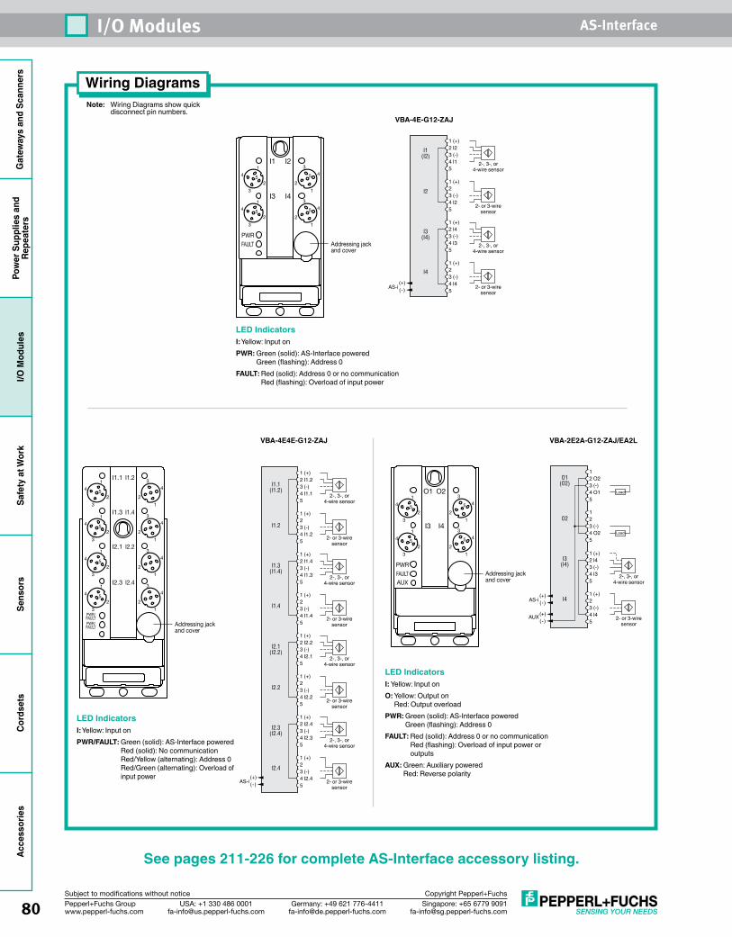
Gat
eway
s an
d Sc
anne
rsPo
wer
Sup
plie
s an
dRe
peat
ers
I/O M
odul
esSa
fety
at W
ork
Sens
ors
Cord
sets
Acce
ssor
ies
80 Singapore: +65 6779 [email protected]
USA: +1 330 486 [email protected]
Germany: +49 621 [email protected]
Pepperl+Fuchs Groupwww.pepperl-fuchs.com
Subject to modifications without notice Copyright Pepperl+Fuchs
I/O Modules AS-Interface
See pages 211-226 for complete AS-Interface accessory listing.
VBA-4E-G12-ZAJ
LED IndicatorsI: Yellow: Input onPWR: Green (solid): AS-Interface powered
Green (flashing): Address 0FAULT: Red (solid): Address 0 or no communication
Red (flashing): Overload of input power
1 (+)2 I43 (-)4 I35
1 (+)2 3 (-)4 I45
12 O23 (-)4 O15
1 2 3 (-)4 O25
Load
Load
2- or 3-wiresensor
O1(O2)
O2
I3(I4)
I4
2-, 3-, or4-wire sensor
(+)(-)
AUX
(+)(-)AS-i
VBA-2E2A-G12-ZAJ/EA2L
4
3
1
25
43
1
2
5
43
1
2
54
3
1
25
O1 O2
I3 I4
PWR
AUXAddressing jackand cover
FAULT
LED IndicatorsI: Yellow: Input onO: Yellow: Output on
Red: Output overloadPWR: Green (solid): AS-Interface powered
Green (flashing): Address 0FAULT: Red (solid): Address 0 or no communication
Red (flashing): Overload of input power or outputs
AUX: Green: Auxiliary powered Red: Reverse polarity
Note: Wiring Diagrams show quick disconnect pin numbers.
Wiring Diagrams
4
3
1
25
43
1
2
5
43
1
2
54
3
1
25
I1 I2
I3 I4
PWRAddressing jackand cover
FAULT
VBA-4E4E-G12-ZAJ
LED IndicatorsI: Yellow: Input onPWR/FAULT: Green (solid): AS-Interface powered
Red (solid): No communication Red/Yellow (alternating): Address 0 Red/Green (alternating): Overload of input power
4
3
1
25
43
1
2
4
3
1
25
43
1
2
4
3
1
25
43
1
2
4
3
1
25
43
1
2
I1.1
I1.3
I1.2
I1.4
I2.1
I2.3
I2.2
I2.4
PWR/FAULTPWR/FAULT Addressing jack
and cover
1 (+)2 I1.23 (-)4 I1.15
1 (+)2
2-, 3-, or4-wire sensor
3 (-)4 I1.25
1 (+)2 I1.4 3 (-)4 I1.35
1 (+)2 3 (-)4 I1.45
2-, 3-, or4-wire sensor
2- or 3-wiresensor
2- or 3-wiresensor
1 (+)2 I2.23 (-)4 I2.15
1 (+)2
2-, 3-, or4-wire sensor
3 (-)4 I2.25
1 (+)2 I2.4 3 (-)4 I2.35
1 (+)2 3 (-)4 I2.45
2-, 3-, or4-wire sensor
2- or 3-wiresensor
2- or 3-wiresensor
I1.1(I1.2)
I1.2
I1.3(I1.4)
I1.4
I2.1(I2.2)
I2.2
I2.3(I2.4)
I2.4
(+)(-)AS-i
1 (+)2 I23 (-)4 I15
1 (+)2
2-, 3-, or4-wire sensor
3 (-)4 I25
1 (+)2 I4 3 (-)4 I35
1 (+)2 3 (-)4 I45
2-, 3-, or4-wire sensor
2- or 3-wiresensor
2- or 3-wiresensor
I1(I2)
I2
I3(I4)
I4
(+)(-)AS-i
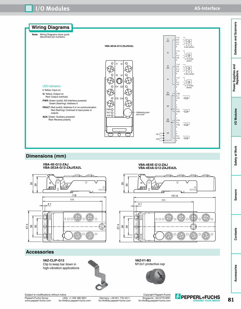
81Singapore: +65 6779 [email protected]
USA: +1 330 486 [email protected]
Germany: +49 621 [email protected]
Pepperl+Fuchs Groupwww.pepperl-fuchs.com
Subject to modifications without notice Copyright Pepperl+Fuchs
I/O Modules AS-Interface
Gat
eway
s an
d Sc
anne
rsPo
wer
Sup
plie
s an
d Re
peat
ers
I/O M
odul
esSa
fety
at W
ork
Sens
ors
Cord
sets
Acce
ssor
ies
Note: Wiring Diagrams show quick disconnect pin numbers.
Wiring Diagrams
1 (+)2 I23 (-)4 I15
1 (+)2
2-, 3-, or4-wire sensor
3 (-)4 I25
1 (+)2 I4 3 (-)4 I35
1 (+)2 3 (-)4 I45
2-, 3-, or4-wire sensor
2- or 3-wiresensor
2- or 3-wiresensor
I1(I2)
I2
I3(I4)
I4
O1(O2)
O2
O3(O4)
O4
12 O23 (-)4 O15
1 2 3 (-)4 O25
Load
Load
1 2 O4 3 (-)4 O35
Load
1 2 3 (-)4 O45
Load(+)(-)
AUX
(+)(-)
AS-i
VBA-4E4A-G12-ZAJ/EA2L
LED IndicatorsI: Yellow: Input onO: Yellow: Output on
Red: Output overloadPWR: Green (solid): AS-Interface powered
Green (flashing): Address 0FAULT: Red (solid): Address 0 or no communication
Red (flashing): Overload of input power or outputs
AUX: Green: Auxiliary powered Red: Reverse polarity
Dimensions (mm)VBA-4E-G12-ZAJVBA-2E2A-G12-ZAJ/EA2L
VBA-4E4E-G12-ZAJVBA-4E4A-G12-ZAJ/EA2L
57.4
39 30
118111
4.1
3035
57.4 39 30
4.1
151.6111
3035
4
3
1
25
43
1
2
4
3
1
25
43
1
2
4
3
1
25
43
1
2
4
3
1
25
43
1
2
I1
I3
I2
I4
O1
O3
O2
O4
PWR
AUXFAULT Addressing jack
and cover
AccessoriesVAZ-CLIP-G12Clip to keep bar down in high-vibration applications
VAZ-V1-B3M12x1 protective cap
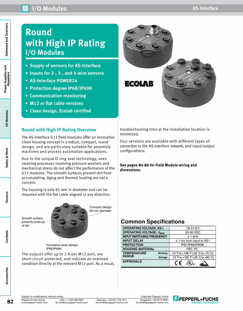
Gat
eway
s an
d Sc
anne
rsPo
wer
Sup
plie
s an
dRe
peat
ers
I/O M
odul
esSa
fety
at W
ork
Sens
ors
Cord
sets
Acce
ssor
ies
82 Singapore: +65 6779 [email protected]
USA: +1 330 486 [email protected]
Germany: +49 621 [email protected]
Pepperl+Fuchs Groupwww.pepperl-fuchs.com
Subject to modifications without notice Copyright Pepperl+Fuchs
I/O Modules AS-Interface
Round with High IP Rating I/O Modules• Supply of sensors for AS-Interface• Inputs for 2-, 3-, and 4-wire sensors• AS-Interface POWER24 • Protection degree IP68/IP69K• Communication monitoring• M12 or flat cable versions• Clean design, Ecolab certified
Round with High IP Rating OverviewThe AS-Interface G11 field modules offer an innovative clean housing concept in a robust, compact, round design, and are particulary suitable for assembly machines and process automation applications.
Due to the unique O-ring seal technology, even cleaning processes involving pressure washers and mechanical stress do not affect the performance of the G11 modules. The smooth surfaces prevent dirt from accumulating. Aging and thermal loading are not a concern.
The housing is only 85 mm in diameter and can be mounted with the flat cable aligned in any direction.
The outputs offer up to 2 A per M12 port, are short-circuit protected, and indicate an overload condition directly at the relevent M12 port. As a result,
troubleshooting time at the installation location is minimized.
Four versions are available with different types of connection to the AS-Interface network, and input/output configurations.
See pages 84-86 for Field Module wiring and dimensions.
Common SpecificationsOPERATING VOLTAGE AS-i 18-31.6 VOPERATING VOLTAGE, VAUX 20-30 VDCINPUT SWITCHING FREQUENCY ≤ 1 kHzINPUT DELAY ≤ 1 ms from input to AS-iPROTECTION IP67/IP68/IP69KHOUSING MATERIAL PBT, PC TEMPERATURE Working -13 F to +158 F (-25 C to +70 C) RANGE Storage -13 F to +185 F (-25 C to +85 C)APPROVALS
Smooth surface prevents build-up of dirt
Compact design85 mm diameter
Innovative clean design IP68/IP69K
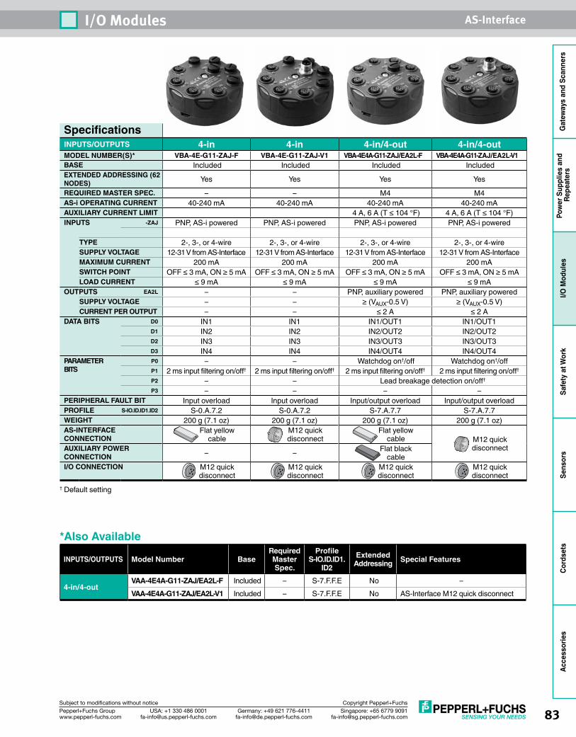
83Singapore: +65 6779 [email protected]
USA: +1 330 486 [email protected]
Germany: +49 621 [email protected]
Pepperl+Fuchs Groupwww.pepperl-fuchs.com
Subject to modifications without notice Copyright Pepperl+Fuchs
I/O Modules AS-Interface
Gat
eway
s an
d Sc
anne
rsPo
wer
Sup
plie
s an
d Re
peat
ers
I/O M
odul
esSa
fety
at W
ork
Sens
ors
Cord
sets
Acce
ssor
ies
SpecificationsINPUTS/OUTPUTS 4-in 4-in 4-in/4-out 4-in/4-outMODEL NUMBER(S)* VBA-4E-G11-ZAJ-F VBA-4E-G11-ZAJ-V1 VBA-4E4A-G11-ZAJ/EA2L-F VBA-4E4A-G11-ZAJ/EA2L-V1BASE Included Included Included IncludedEXTENDED ADDRESSING (62 NODES) Yes Yes Yes Yes
REQUIRED MASTER SPEC. – – M4 M4AS-i OPERATING CURRENT 40-240 mA 40-240 mA 40-240 mA 40-240 mAAUXILIARY CURRENT LIMIT 4 A, 6 A (T ≤ 104 °F) 4 A, 6 A (T ≤ 104 °F) INPUTS -ZAJ PNP, AS-i powered PNP, AS-i powered PNP, AS-i powered PNP, AS-i powered
TYPE 2-, 3-, or 4-wire 2-, 3-, or 4-wire 2-, 3-, or 4-wire 2-, 3-, or 4-wireSUPPLY VOLTAGE 12-31 V from AS-Interface 12-31 V from AS-Interface 12-31 V from AS-Interface 12-31 V from AS-InterfaceMAXIMUM CURRENT 200 mA 200 mA 200 mA 200 mASWITCH POINT OFF ≤ 3 mA, ON ≥ 5 mA OFF ≤ 3 mA, ON ≥ 5 mA OFF ≤ 3 mA, ON ≥ 5 mA OFF ≤ 3 mA, ON ≥ 5 mALOAD CURRENT ≤ 9 mA ≤ 9 mA ≤ 9 mA ≤ 9 mA
OUTPUTS EA2L – – PNP, auxiliary powered PNP, auxiliary poweredSUPPLY VOLTAGE – – ≥ (VAUX-0.5 V) ≥ (VAUX-0.5 V)CURRENT PER OUTPUT – – ≤ 2 A ≤ 2 A
DATA BITS D0 IN1 IN1 IN1/OUT1 IN1/OUT1D1 IN2 IN2 IN2/OUT2 IN2/OUT2D2 IN3 IN3 IN3/OUT3 IN3/OUT3D3 IN4 IN4 IN4/OUT4 IN4/OUT4
PARAMETER BITS
P0 – – Watchdog on†/off Watchdog on†/off P1 2 ms input filtering on/off† 2 ms input filtering on/off† 2 ms input filtering on/off† 2 ms input filtering on/off†
P2 – – Lead breakage detection on/off†
P3 – – – – PERIPHERAL FAULT BIT Input overload Input overload Input/output overload Input/output overload PROFILE S-IO.ID.ID1.ID2 S-0.A.7.2 S-0.A.7.2 S-7.A.7.7 S-7.A.7.7WEIGHT 200 g (7.1 oz) 200 g (7.1 oz) 200 g (7.1 oz) 200 g (7.1 oz)AS-INTERFACE CONNECTION
Flat yellow cable
M12 quickdisconnect
Flat yellow cable M12 quick
disconnectAUXILIARY POWER CONNECTION – – Flat black
cableI/O CONNECTION M12 quick
disconnectM12 quickdisconnect
M12 quickdisconnect
M12 quickdisconnect
† Default setting
*Also Available
INPUTS/OUTPUTS Model Number BaseRequired Master Spec.
Profile S-IO.ID.ID1.
ID2Extended
Addressing Special Features
4-in/4-outVAA-4E4A-G11-ZAJ/EA2L-F Included – S-7.F.F.E No –VAA-4E4A-G11-ZAJ/EA2L-V1 Included – S-7.F.F.E No AS-Interface M12 quick disconnect
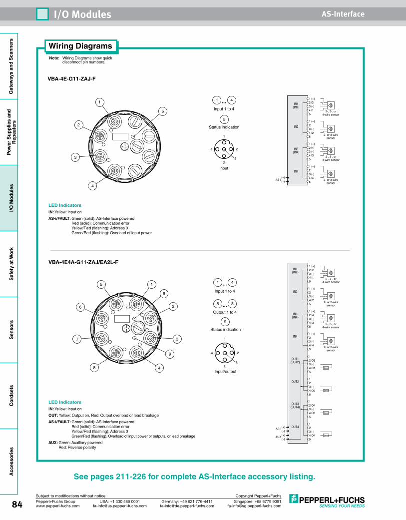
Gat
eway
s an
d Sc
anne
rsPo
wer
Sup
plie
s an
dRe
peat
ers
I/O M
odul
esSa
fety
at W
ork
Sens
ors
Cord
sets
Acce
ssor
ies
84 Singapore: +65 6779 [email protected]
USA: +1 330 486 [email protected]
Germany: +49 621 [email protected]
Pepperl+Fuchs Groupwww.pepperl-fuchs.com
Subject to modifications without notice Copyright Pepperl+Fuchs
I/O Modules AS-Interface
See pages 211-226 for complete AS-Interface accessory listing.
Note: Wiring Diagrams show quick disconnect pin numbers.
Wiring Diagrams
1 (+)2 I23 (-)4 I15
1 (+)2
2-, 3-, or4-wire sensor
3 (-)4 I25
1 (+)2 I4 3 (-)4 I35
1 (+)2 3 (-)4 I45
2-, 3-, or4-wire sensor
2- or 3-wiresensor
2- or 3-wiresensor
IN1(IN2)
IN2
IN3(IN4)
IN4
OUT1(OUT2)
OUT2
OUT3(OUT4)
OUT4
12 O23 (-)4 O15
1 2 3 (-)4 O25
Load
Load
1 2 O4 3 (-)4 O35
Load
1 2 3 (-)4 O45
Load(+)(-)
AUX
(+)(-)
AS-i
VBA-4E4A-G11-ZAJ/EA2L-F
VBA-4E-G11-ZAJ-F
1 (+)2 I23 (-)4 I15
1 (+)2
2-, 3-, or4-wire sensor
3 (-)4 I25
1 (+)2 I4 3 (-)4 I35
1 (+)2 3 (-)4 I45
2-, 3-, or4-wire sensor
2- or 3-wiresensor
2- or 3-wiresensor
IN1(IN2)
IN2
IN3(IN4)
IN4
(+)(-)AS-i
Input 1 to 4
Status indication
5
1 4...
5
1
2
3
4
1
4
35
2
Input
LED IndicatorsIN: Yellow: Input onAS-i/FAULT: Green (solid): AS-Interface powered
Red (solid): Communication error Yellow/Red (flashing): Address 0 Green/Red (flashing): Overload of input power
Input 1 to 4
Output 1 to 4
Status indication
9
1 1 4...
5 8...
9
2
3
4
5
6
7
8
9
1
4
35
2
Input/output
LED IndicatorsIN: Yellow: Input onOUT: Yellow: Output on, Red: Output overload or lead breakageAS-i/FAULT: Green (solid): AS-Interface powered
Red (solid): Communication error Yellow/Red (flashing): Address 0 Green/Red (flashing): Overload of input power or outputs, or lead breakage
AUX: Green: Auxiliary powered Red: Reverse polarity
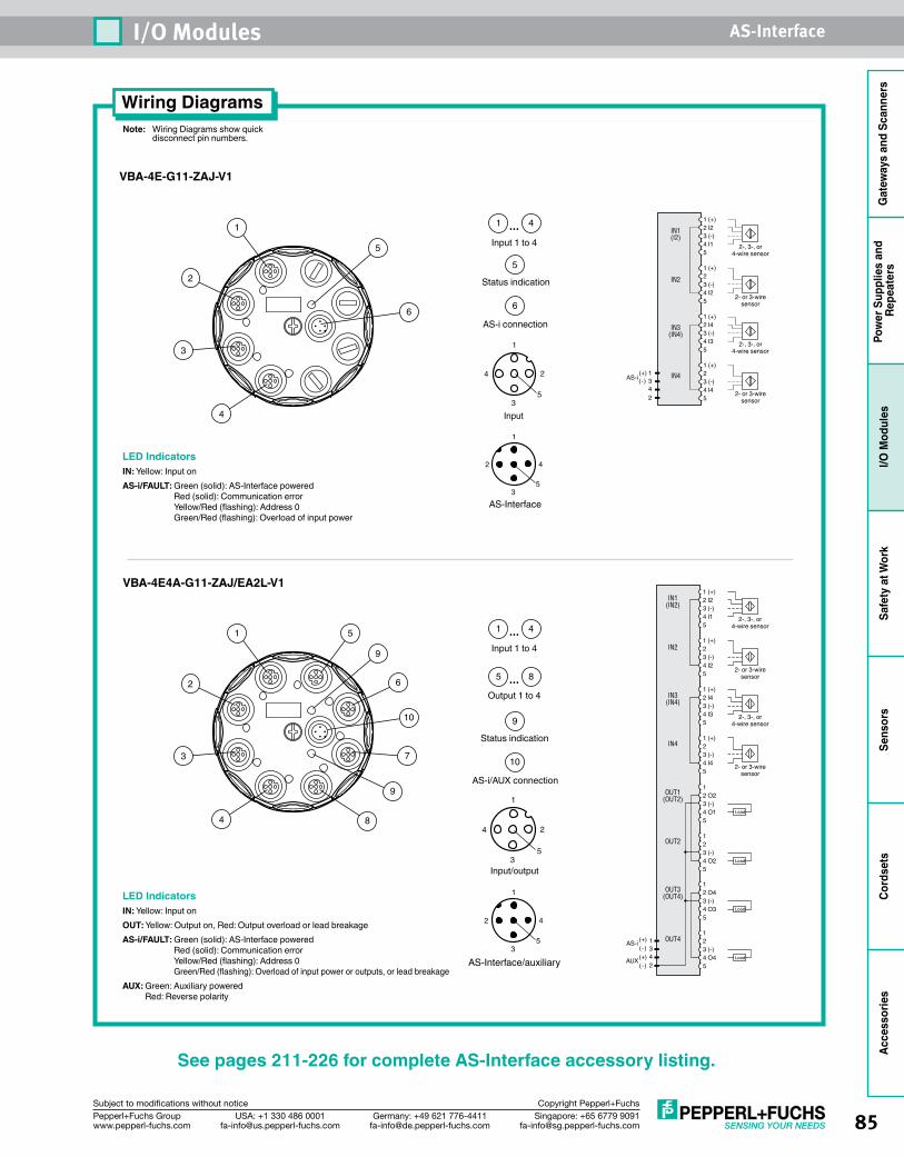
85Singapore: +65 6779 [email protected]
USA: +1 330 486 [email protected]
Germany: +49 621 [email protected]
Pepperl+Fuchs Groupwww.pepperl-fuchs.com
Subject to modifications without notice Copyright Pepperl+Fuchs
I/O Modules AS-Interface
Gat
eway
s an
d Sc
anne
rsPo
wer
Sup
plie
s an
d Re
peat
ers
I/O M
odul
esSa
fety
at W
ork
Sens
ors
Cord
sets
Acce
ssor
ies
1 (+)2 I23 (-)4 I15
1 (+)2
2-, 3-, or4-wire sensor
3 (-)4 I25
1 (+)2 I4 3 (-)4 I35
1 (+)2 3 (-)4 I45
2-, 3-, or4-wire sensor
2- or 3-wiresensor
2- or 3-wiresensor
IN1(I2)
IN2
IN3(IN4)
IN4(+) 1(-) 3 4 2
AS-i
1
2 4
35
AS-Interface
1
4
35
2
Input
Input 1 to 4
Status indication
AS-i connection
5
6
1 4...
5
6
1
2
3
4
Input 1 to 4
Output 1 to 4
Status indication
AS-i/AUX connection
9
5
10
1 4...
5 8...
9
10
6
7
8
1
2
3
4
9
See pages 211-226 for complete AS-Interface accessory listing.
Note: Wiring Diagrams show quick disconnect pin numbers.
Wiring Diagrams
VBA-4E4A-G11-ZAJ/EA2L-V1
VBA-4E-G11-ZAJ-V1
1 (+)2 I23 (-)4 I15
1 (+)2
2-, 3-, or4-wire sensor
3 (-)4 I25
1 (+)2 I4 3 (-)4 I35
1 (+)2 3 (-)4 I45
2-, 3-, or4-wire sensor
2- or 3-wiresensor
2- or 3-wiresensor
IN1(IN2)
IN2
IN3(IN4)
IN4
OUT1(OUT2)
OUT2
OUT3(OUT4)
OUT4
12 O23 (-)4 O15
1 2 3 (-)4 O25
Load
Load
1 2 O4 3 (-)4 O35
Load
1 2 3 (-)4 O45
Load(+)(-)
AUX
(+)(-)
AS-i 1342
LED IndicatorsIN: Yellow: Input onAS-i/FAULT: Green (solid): AS-Interface powered
Red (solid): Communication error Yellow/Red (flashing): Address 0 Green/Red (flashing): Overload of input power
1
2 4
35
AS-Interface/auxiliary
1
4
35
2
Input/output
LED IndicatorsIN: Yellow: Input onOUT: Yellow: Output on, Red: Output overload or lead breakageAS-i/FAULT: Green (solid): AS-Interface powered
Red (solid): Communication error Yellow/Red (flashing): Address 0 Green/Red (flashing): Overload of input power or outputs, or lead breakage
AUX: Green: Auxiliary powered Red: Reverse polarity
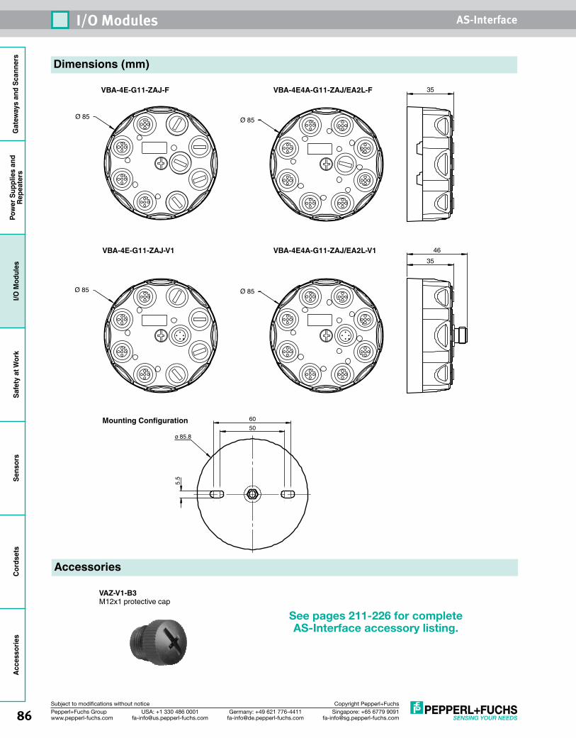
Gat
eway
s an
d Sc
anne
rsPo
wer
Sup
plie
s an
dRe
peat
ers
I/O M
odul
esSa
fety
at W
ork
Sens
ors
Cord
sets
Acce
ssor
ies
86 Singapore: +65 6779 [email protected]
USA: +1 330 486 [email protected]
Germany: +49 621 [email protected]
Pepperl+Fuchs Groupwww.pepperl-fuchs.com
Subject to modifications without notice Copyright Pepperl+Fuchs
I/O Modules AS-Interface
Dimensions (mm)
Accessories
See pages 211-226 for complete AS-Interface accessory listing.
3546
Ø 85Ø 85
VBA-4E-G11-ZAJ-F 35
Ø 85Ø 85
VBA-4E4A-G11-ZAJ/EA2L-F
VBA-4E-G11-ZAJ-V1 VBA-4E4A-G11-ZAJ/EA2L-V1
VAZ-V1-B3M12x1 protective cap
5.5
5060
ø 85.8
Mounting Configuration
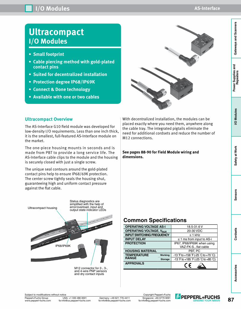
87Singapore: +65 6779 [email protected]
USA: +1 330 486 [email protected]
Germany: +49 621 [email protected]
Pepperl+Fuchs Groupwww.pepperl-fuchs.com
Subject to modifications without notice Copyright Pepperl+Fuchs
I/O Modules AS-Interface
Gat
eway
s an
d Sc
anne
rsPo
wer
Sup
plie
s an
d Re
peat
ers
I/O M
odul
esSa
fety
at W
ork
Sens
ors
Cord
sets
Acce
ssor
ies
UltracompactI/O Modules• Small footprint• Cable piercing method with gold-plated
contact pins• Suited for decentralized installation • Protection degree IP68/IP69K• Connect & Done technology• Available with one or two cables
Ultracompact OverviewThe AS-Interface G10 field module was developed for low-density I/O requirements. Less than one inch thick, it is the smallest, full-featured AS-Interface module on the market.
The one-piece housing mounts in seconds and is made from PBT to provide a long service life. The AS-Interface cable clips to the module and the housing is securely closed with just a single screw.
The unique seal contours around the gold-plated contact pins help to ensure IP68/69K protection. The center screw tightly seals the housing shut, guaranteeing high and uniform contact pressure against the flat cable.
With decentralized installation, the modules can be placed exactly where you need them, anywhere along the cable tray. The integrated pigtails eliminate the need for additional cordsets and reduce the number of M12 connections.
See pages 88-90 for Field Module wiring and dimensions.
Common SpecificationsOPERATING VOLTAGE AS-i 18.5-31.6 VOPERATING VOLTAGE, VAUX 20-30 VDCINPUT SWITCHING FREQUENCY ≤ 1 kHzINPUT DELAY ≤ 1 ms from input to AS-iPROTECTION IP67, IP68/IP69K when using
VAZ-FK-S...flat cableHOUSING MATERIAL PBT, PC TEMPERATURE Working -13 F to +158 F (-25 C to +70 C) RANGE Storage -13 F to +185 F (-25 C to +85 C)APPROVALS
Status diagnostics are simplified with the help of error/overload, input and output state indicator LEDsUltracompact housing
IP68/IP69K
M12 connector for 2-, 3-, and 4-wire PNP sensors and dry contact inputs
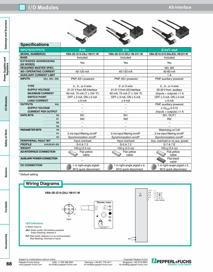
Gat
eway
s an
d Sc
anne
rsPo
wer
Sup
plie
s an
dRe
peat
ers
I/O M
odul
esSa
fety
at W
ork
Sens
ors
Cord
sets
Acce
ssor
ies
88 Singapore: +65 6779 [email protected]
USA: +1 330 486 [email protected]
Germany: +49 621 [email protected]
Pepperl+Fuchs Groupwww.pepperl-fuchs.com
Subject to modifications without notice Copyright Pepperl+Fuchs
I/O Modules AS-Interface
SpecificationsINPUTS/OUTPUTS 2-in 2-in 2-in/1-outMODEL NUMBER(S) VBA-2E-G10-ZAJ-1M-V1-W VBA-2E-G10-ZEJ-1M-2V1-W VBA-2E1A-G10-ZAL/E2L-1M-2V1-WBASE Included Included IncludedEXTENDED ADDRESSING (62 NODES) Yes Yes Yes
REQUIRED MASTER SPEC. – – M3, M4AS-i OPERATING CURRENT 40-120 mA 40-120 mA 40-60 mAAUXILIARY CURRENT LIMIT – – 1 AINPUTS -ZAJ, -ZEJ, -ZAL PNP, AS-i powered PNP, AS-i powered PNP, auxiliary powered
TYPE 2-, 3-, or 4-wire 2- or 3-wire 2-, 3-, or 4-wireSUPPLY VOLTAGE 21-31 V from AS-Interface 21-31 V from AS-Interface 20-30 V from auxiliaryMAXIMUM CURRENT 60 mA, 75 mA (T ≤ 104 °F) 60 mA, 75 mA (T ≤ 104 °F) (Inputs + outputs) <1 ASWITCH POINT OFF ≤ 3 mA, ON ≥ 5 mA OFF ≤ 3 mA, ON ≥ 5 mA OFF ≤ 3 mA, ON ≥ 5 mALOAD CURRENT ≤ 9 mA ≤ 9 mA ≤ 9 mA
OUTPUTS E2L – – PNP, auxiliary poweredSUPPLY VOLTAGE – – ≥ (VAUX-0.5 V)CURRENT PER OUTPUT – – (Inputs + outputs) <1 A
DATA BITS D0 IN1 IN1 IN1, OUT1D1 IN2 IN2 IN2D2 – – –D3 – – –
PARAMETER BITS P0 – – Watchdog on†/off P1 2 ms input filtering on/off† 2 ms input filtering on/off† 2 ms input filtering on/off†
P2 Synchronization on/off† Synchronization on/off† Synchronization on/off†
PERIPHERAL FAULT BIT Input overload Input overload Aux. overload or no aux. powerPROFILE S-IO.ID.ID1.ID2 S-0.A.7.2 S-0.A.7.2 S-7.A.7.EWEIGHT 100 g (3.5 oz) 100 g (3.5 oz) 100 g (3.5 oz)AS-INTERFACE CONNECTION Flat yellow
cableFlat yellow
cableFlat yellow
cableAUXILIARY POWER CONNECTION – – Flat black
cableI/O CONNECTION 1 m right-angle pigtail,
M12 quick disconnect1 m right-angle pigtail x 2,
M12 quick disconnect1 m right-angle pigtail x 2,
M12 quick disconnect† Default setting
VBA-2E-G10-ZAJ-1M-V1-W1 (+)2 I23 (-)4 I15
I1(I2)
(+)(-)AS-i
2-, 3-, or4-wire sensor
1
4
35
2
Input
Part No. 221247VBA-2E-G10-ZAJ-1M-V1-W
AS-i
3.13.2
1.1: I1.2: I2
+1.3: I –1.4: I1
AS-i
FLT
I1
I2
+–
Wiring Diagrams
LED IndicatorsI: Yellow: Input onAS-i: Green (solid): AS-Interface powered
Green (flashing): Address 0FLT: Red (solid): Address 0 or no communication
Red (flashing): Overload of inputs
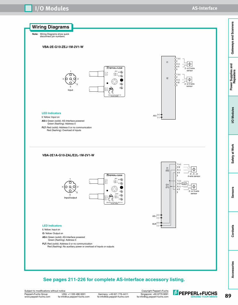
89Singapore: +65 6779 [email protected]
USA: +1 330 486 [email protected]
Germany: +49 621 [email protected]
Pepperl+Fuchs Groupwww.pepperl-fuchs.com
Subject to modifications without notice Copyright Pepperl+Fuchs
I/O Modules AS-Interface
Gat
eway
s an
d Sc
anne
rsPo
wer
Sup
plie
s an
d Re
peat
ers
I/O M
odul
esSa
fety
at W
ork
Sens
ors
Cord
sets
Acce
ssor
ies
See pages 211-226 for complete AS-Interface accessory listing.
Note: Wiring Diagrams show quick disconnect pin numbers.
Wiring Diagrams
VBA-2E1A-G10-ZAL/E2L-1M-2V1-W
1
4
35
2
Input/output
LED IndicatorsI: Yellow: Input onO: Yellow: Output onAS-i: Green (solid): AS-Interface powered
Green (flashing): Address 0FLT: Red (solid): Address 0 or no communication
Red (flashing): No auxiliary power or overload of inputs or outputs
VBA-2E-G10-ZEJ-1M-2V1-W
1 (+)2 3 (-)4 I15
1 (+)2 3 (-)4 I25
I1
I2
(+)(-)
AS-i
2- or 3-wiresensor
2- or 3-wiresensor
LED IndicatorsI: Yellow: Input onAS-i: Green (solid): AS-Interface powered
Green (flashing): Address 0FLT: Red (solid): Address 0 or no communication
Red (flashing): Overload of inputs
Part No. 233665VBA-2E-G10-ZEJ-1M-2V1-W
AS-i
3.13.2
1.1: I+1.3: I –1.4: I1
AS-i
FLT
I1
I2
+–
2.1: I2.3: I
+2.4: I2
–
1
4
35
2
Input
Part No. 216025VBA-2E1A-G10-ZAL/E2L-1M-2V1-W
2.1:2.2: O1
AS-i
3.13.2
AUX
4.14.2
1.1:1.2: I2
+1.3: –1.4: I1
AS-I
FLT
I1
O1
I2
+–
+–2.3:
+–
2.4: I1
1 (+)2 I23 (-)4 I15
1 (+)2 O1 3 (-)4 I15
I1(I2)
O1(I1)
(+)(-)
AUX
(+)(-)
AS-i
Load
2-, 3-, or4-wire sensor
2- or 3-wiresensor
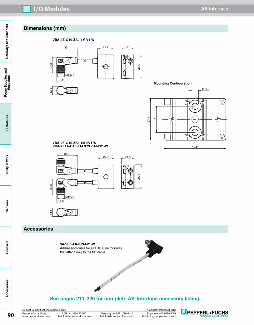
Gat
eway
s an
d Sc
anne
rsPo
wer
Sup
plie
s an
dRe
peat
ers
I/O M
odul
esSa
fety
at W
ork
Sens
ors
Cord
sets
Acce
ssor
ies
90 Singapore: +65 6779 [email protected]
USA: +1 330 486 [email protected]
Germany: +49 621 [email protected]
Pepperl+Fuchs Groupwww.pepperl-fuchs.com
Subject to modifications without notice Copyright Pepperl+Fuchs
I/O Modules AS-Interface
27.7 21.5
40.5
27.8
14.8
14.2
M12x1
35.1
Dimensions (mm)
Accessories
See pages 211-226 for complete AS-Interface accessory listing.
VBA-2E-G10-ZEJ-1M-2V1-WVBA-2E1A-G10-ZAL/E2L-1M-2V1-W
VBA-2E-G10-ZAJ-1M-V1-W
27.7 21.5
40.5
27.8
14.8
14.2
M12x1
35.1
VAZ-PK-FK-0,2M-V1-WAddressing cable for all G10 style modules that attach only to the flat cable
1727.7
40.5
Ø 4.2
Mounting Configuration
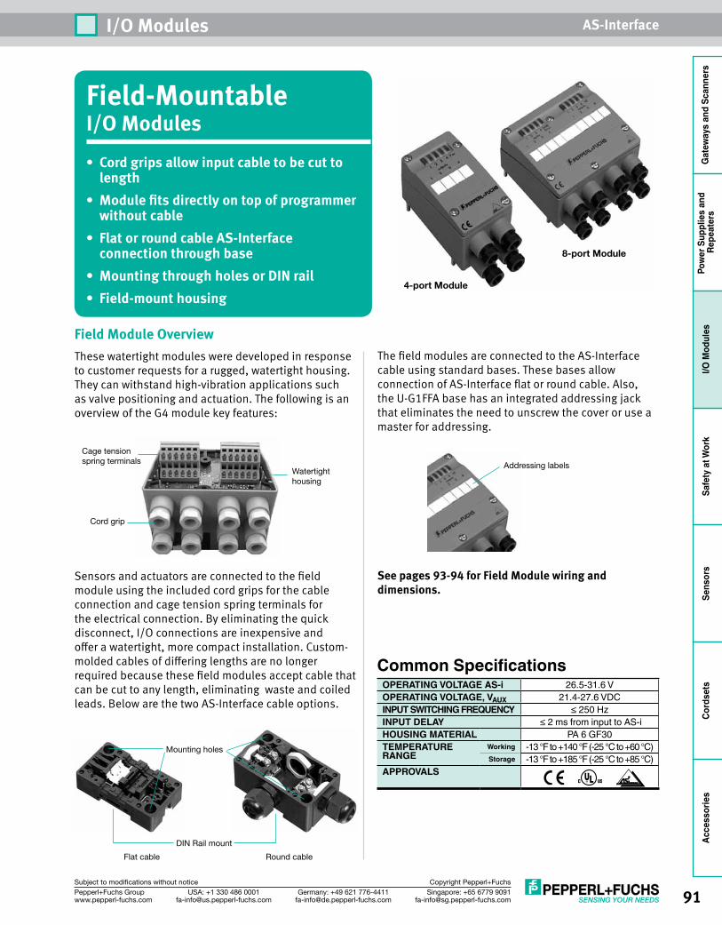
91Singapore: +65 6779 [email protected]
USA: +1 330 486 [email protected]
Germany: +49 621 [email protected]
Pepperl+Fuchs Groupwww.pepperl-fuchs.com
Subject to modifications without notice Copyright Pepperl+Fuchs
I/O Modules AS-Interface
Gat
eway
s an
d Sc
anne
rsPo
wer
Sup
plie
s an
d Re
peat
ers
I/O M
odul
esSa
fety
at W
ork
Sens
ors
Cord
sets
Acce
ssor
ies
Field-MountableI/O Modules• Cord grips allow input cable to be cut to
length• Module fits directly on top of programmer
without cable• Flat or round cable AS-Interface
connection through base• Mounting through holes or DIN rail• Field-mount housing
8-port Module
4-port Module
Field Module OverviewThese watertight modules were developed in response to customer requests for a rugged, watertight housing. They can withstand high-vibration applications such as valve positioning and actuation. The following is an overview of the G4 module key features:
Sensors and actuators are connected to the field module using the included cord grips for the cable connection and cage tension spring terminals for the electrical connection. By eliminating the quick disconnect, I/O connections are inexpensive and offer a watertight, more compact installation. Custom-molded cables of differing lengths are no longer required because these field modules accept cable that can be cut to any length, eliminating waste and coiled leads. Below are the two AS-Interface cable options.
The field modules are connected to the AS-Interface cable using standard bases. These bases allow connection of AS-Interface flat or round cable. Also, the U-G1FFA base has an integrated addressing jack that eliminates the need to unscrew the cover or use a master for addressing.
See pages 93-94 for Field Module wiring and dimensions.
Flat cable
DIN Rail mount
Mounting holes
Round cable
Cage tensionspring terminals
Watertighthousing
Cord grip
Addressing labels
Common SpecificationsOPERATING VOLTAGE AS-i 26.5-31.6 VOPERATING VOLTAGE, VAUX 21.4-27.6 VDCINPUT SWITCHING FREQUENCY ≤ 250 HzINPUT DELAY ≤ 2 ms from input to AS-iHOUSING MATERIAL PA 6 GF30TEMPERATURE Working -13 °F to +140 °F (-25 °C to +60 °C)RANGE Storage -13 °F to +185 °F (-25 °C to +85 °C)APPROVALS
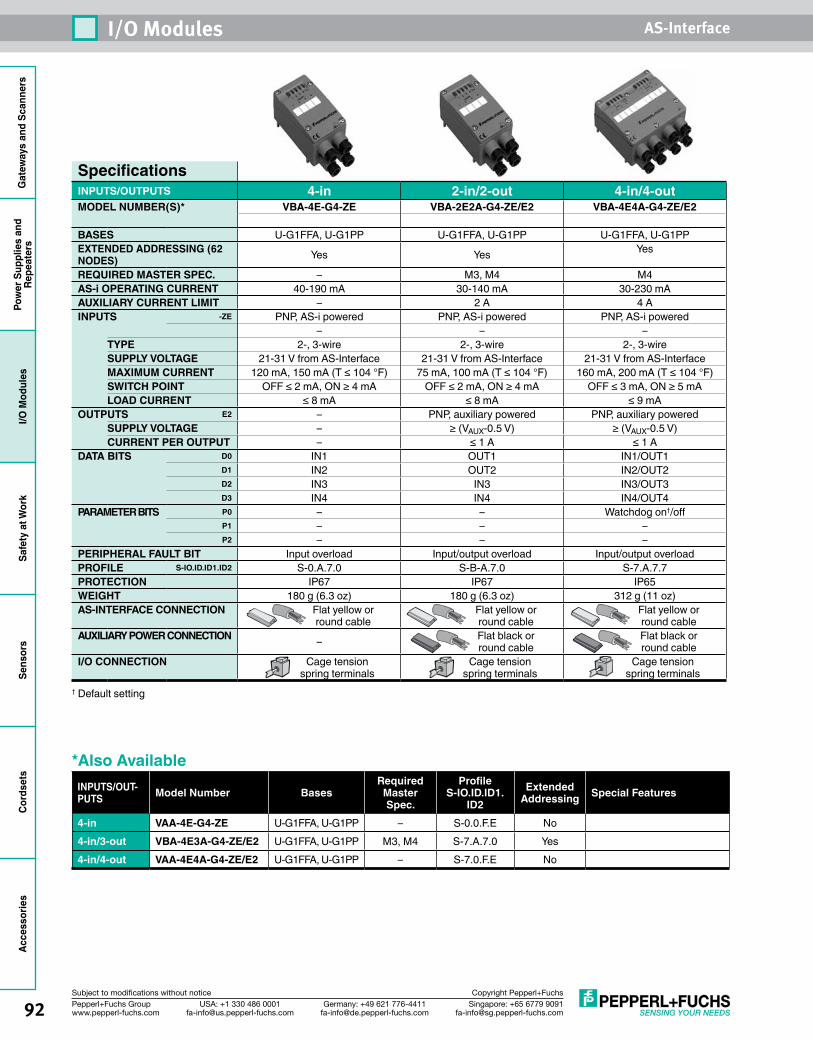
Gat
eway
s an
d Sc
anne
rsPo
wer
Sup
plie
s an
dRe
peat
ers
I/O M
odul
esSa
fety
at W
ork
Sens
ors
Cord
sets
Acce
ssor
ies
92 Singapore: +65 6779 [email protected]
USA: +1 330 486 [email protected]
Germany: +49 621 [email protected]
Pepperl+Fuchs Groupwww.pepperl-fuchs.com
Subject to modifications without notice Copyright Pepperl+Fuchs
I/O Modules AS-Interface
SpecificationsINPUTS/OUTPUTS 4-in 2-in/2-out 4-in/4-outMODEL NUMBER(S)* VBA-4E-G4-ZE VBA-2E2A-G4-ZE/E2 VBA-4E4A-G4-ZE/E2
BASES U-G1FFA, U-G1PP U-G1FFA, U-G1PP U-G1FFA, U-G1PPEXTENDED ADDRESSING (62 NODES) Yes Yes Yes
REQUIRED MASTER SPEC. – M3, M4 M4AS-i OPERATING CURRENT 40-190 mA 30-140 mA 30-230 mAAUXILIARY CURRENT LIMIT – 2 A 4 AINPUTS -ZE PNP, AS-i powered PNP, AS-i powered PNP, AS-i powered
– – –TYPE 2-, 3-wire 2-, 3-wire 2-, 3-wireSUPPLY VOLTAGE 21-31 V from AS-Interface 21-31 V from AS-Interface 21-31 V from AS-InterfaceMAXIMUM CURRENT 120 mA, 150 mA (T ≤ 104 °F) 75 mA, 100 mA (T ≤ 104 °F) 160 mA, 200 mA (T ≤ 104 °F)SWITCH POINT OFF ≤ 2 mA, ON ≥ 4 mA OFF ≤ 2 mA, ON ≥ 4 mA OFF ≤ 3 mA, ON ≥ 5 mALOAD CURRENT ≤ 8 mA ≤ 8 mA ≤ 9 mA
OUTPUTS E2 – PNP, auxiliary powered PNP, auxiliary poweredSUPPLY VOLTAGE – ≥ (VAUX-0.5 V) ≥ (VAUX-0.5 V)CURRENT PER OUTPUT – ≤ 1 A ≤ 1 A
DATA BITS D0 IN1 OUT1 IN1/OUT1D1 IN2 OUT2 IN2/OUT2D2 IN3 IN3 IN3/OUT3D3 IN4 IN4 IN4/OUT4
PARAMETER BITS P0 – – Watchdog on†/offP1 – – –P2 – – –
PERIPHERAL FAULT BIT Input overload Input/output overload Input/output overloadPROFILE S-IO.ID.ID1.ID2 S-0.A.7.0 S-B-A.7.0 S-7.A.7.7PROTECTION IP67 IP67 IP65WEIGHT 180 g (6.3 oz) 180 g (6.3 oz) 312 g (11 oz)AS-INTERFACE CONNECTION Flat yellow or
round cableFlat yellow or round cable
Flat yellow or round cable
AUXILIARY POWER CONNECTION – Flat black or round cable
Flat black or round cable
I/O CONNECTION Cage tension spring terminals
Cage tension spring terminals
Cage tension spring terminals
† Default setting
*Also AvailableINPUTS/OUT-PUTS Model Number Bases
Required Master Spec.
Profile S-IO.ID.ID1.
ID2Extended
Addressing Special Features
4-in VAA-4E-G4-ZE U-G1FFA, U-G1PP – S-0.0.F.E No4-in/3-out VBA-4E3A-G4-ZE/E2 U-G1FFA, U-G1PP M3, M4 S-7.A.7.0 Yes4-in/4-out VAA-4E4A-G4-ZE/E2 U-G1FFA, U-G1PP – S-7.0.F.E No
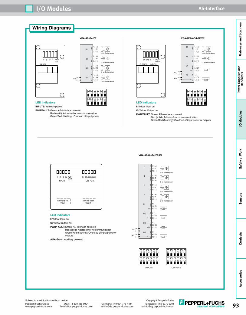
93Singapore: +65 6779 [email protected]
USA: +1 330 486 [email protected]
Germany: +49 621 [email protected]
Pepperl+Fuchs Groupwww.pepperl-fuchs.com
Subject to modifications without notice Copyright Pepperl+Fuchs
I/O Modules AS-Interface
Gat
eway
s an
d Sc
anne
rsPo
wer
Sup
plie
s an
d Re
peat
ers
I/O M
odul
esSa
fety
at W
ork
Sens
ors
Cord
sets
Acce
ssor
ies
Wiring Diagrams
3.1 3.2 3.3 4.1 4.2 4.3
1.1 1.2 1.3 2.1 2.2 2.3
3.1 3.2 3.3 4.1 4.2 4.3
1.1 1.2 1.3 2.1 2.2 2.3
INPUTS OUTPUTS
1.1 (+)1.2 IN11.3 (-)
2- or 3-wire sensor
IN1
2.1 (+)2.2 IN22.3 (-)
2- or 3-wire sensor
IN2
3.1 (+)3.2 IN33.3 (-)
2- or 3-wire sensor
IN3
4.1 (+)4.2 IN44.3 (-)
2- or 3-wire sensor
IN4(+)(-)
AS-i
VBA-4E-G4-ZE
1.1 (+)1.2 I31.3 (-)
2- or 3-wire sensor
I3
2.1 (+)2.2 I42.3 (-)
2- or 3-wire sensor
I4
3.1 3.2 O13.3 (-)
O1
4.1 4.2 O24.3 (-)
O2
Load
Load
(+)(-)
AUX
(+)(-)
AS_i
VBA-2E2A-G4-ZE/E2
3.1 3.2 3.3 4.1 4.2 4.3
1.1 1.2 1.3 2.1 2.2 2.3
3.1 3.2 3.3 4.1 4.2 4.3
1.1 1.2 1.3 2.1 2.2 2.3
INPUTS OUTPUTS
1.1 (+)1.2 I11.3 (-)
2- or 3-wire sensor
I1
2.1 (+)2.2 I22.3 (-)
2- or 3-wire sensor
2- or 3-wire sensor
2- or 3-wire sensor
I2
3.1 (+)3.2 I33.3 (-)
I3
4.1 (+)4.2 I44.3 (-)
1.1 1.2 O11.3 (-)
2.1 2.2 O22.3 (-)
3.1 3.2 O33.3 (-)
4.1 4.2 O44.3 (-)
I4
O1
O2
O3
O4
Load
Load
Load
Load
(+)(-)
AUX
(+)(-)
AS-i
VBA-4E4A-G4-ZE/E2
1 2 3 4 PWR/ FAULT
INPUTS
O1 O2 I3 I4 PWR/ FAULT
OUTPUTS INPUTS
3.1 3.2 3.3 4.1 4.2 4.3
1.1 1.2 1.3 2.1 2.2 2.3
3.1 3.2 3.3 4.1 4.2 4.3
1.1 1.2 1.3 2.1 2.2 2.3
INPUTS OUTPUTS
LED IndicatorsINPUTS: Yellow: Input onPWR/FAULT: Green: AS-Interface powered
Red (solid): Address 0 or no communication Green/Red (flashing): Overload of input power
LED IndicatorsI: Yellow: Input onO: Yellow: Output onPWR/FAULT: Green: AS-Interface powered
Red (solid): Address 0 or no communication Green/Red (flashing): Overload of input power or outputs
LED IndicatorsI: Yellow: Input onO: Yellow: Output onPWR/FAULT: Green: AS-Interface powered
Red (solid): Address 0 or no communication Green/Red (flashing): Overload of input power or outputs
AUX: Green: Auxiliary powered
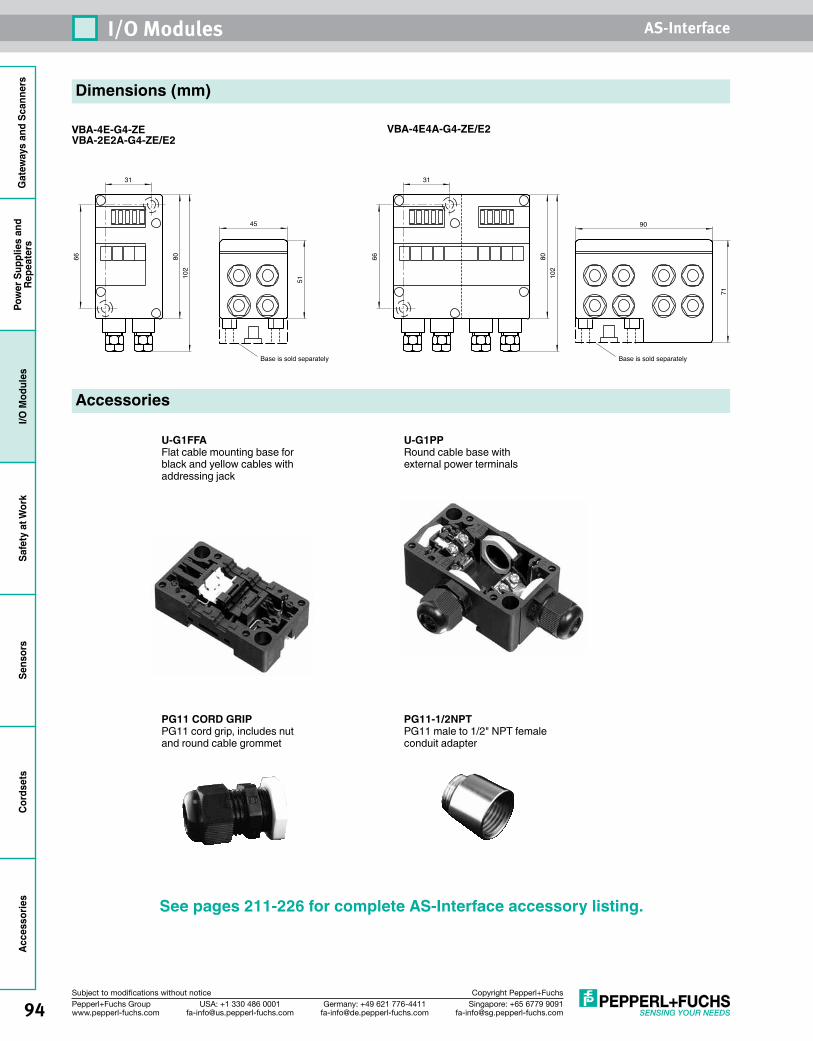
Gat
eway
s an
d Sc
anne
rsPo
wer
Sup
plie
s an
dRe
peat
ers
I/O M
odul
esSa
fety
at W
ork
Sens
ors
Cord
sets
Acce
ssor
ies
94 Singapore: +65 6779 [email protected]
USA: +1 330 486 [email protected]
Germany: +49 621 [email protected]
Pepperl+Fuchs Groupwww.pepperl-fuchs.com
Subject to modifications without notice Copyright Pepperl+Fuchs
I/O Modules AS-Interface
Dimensions (mm)
VBA-4E-G4-ZEVBA-2E2A-G4-ZE/E2
Accessories
VBA-4E4A-G4-ZE/E2
Base is sold separately
31
66 8010
2
51
45
Base is sold separately
71
90
31
66 8010
2
U-G1FFAFlat cable mounting base for black and yellow cables withaddressing jack
U-G1PPRound cable base with external power terminals
PG11 CORD GRIPPG11 cord grip, includes nut and round cable grommet
PG11-1/2NPTPG11 male to 1/2" NPT female conduit adapter
See pages 211-226 for complete AS-Interface accessory listing.
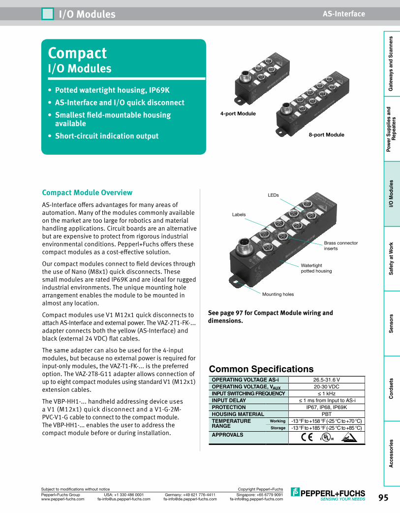
95Singapore: +65 6779 [email protected]
USA: +1 330 486 [email protected]
Germany: +49 621 [email protected]
Pepperl+Fuchs Groupwww.pepperl-fuchs.com
Subject to modifications without notice Copyright Pepperl+Fuchs
I/O Modules AS-Interface
Gat
eway
s an
d Sc
anne
rsPo
wer
Sup
plie
s an
d Re
peat
ers
I/O M
odul
esSa
fety
at W
ork
Sens
ors
Cord
sets
Acce
ssor
ies
CompactI/O Modules• Potted watertight housing, IP69K• AS-Interface and I/O quick disconnect• Smallest field-mountable housing
available• Short-circuit indication output
Compact Module OverviewAS-Interface offers advantages for many areas of automation. Many of the modules commonly available on the market are too large for robotics and material handling applications. Circuit boards are an alternative but are expensive to protect from rigorous industrial environmental conditions. Pepperl+Fuchs offers these compact modules as a cost-effective solution.
Our compact modules connect to field devices through the use of Nano (M8x1) quick disconnects. These small modules are rated IP69K and are ideal for rugged industrial environments. The unique mounting hole arrangement enables the module to be mounted in almost any location.
Compact modules use V1 M12x1 quick disconnects to attach AS-Interface and external power. The VAZ-2T1-FK-... adapter connects both the yellow (AS-Interface) and black (external 24 VDC) flat cables.
The same adapter can also be used for the 4-input modules, but because no external power is required for input-only modules, the VAZ-T1-FK-... is the preferred option. The VAZ-2T8-G11 adapter allows connection of up to eight compact modules using standard V1 (M12x1) extension cables.
The VBP-HH1-... handheld addressing device uses a V1 (M12x1) quick disconnect and a V1-G-2M-PVC-V1-G cable to connect to the compact module. The VBP-HH1-... enables the user to address the compact module before or during installation.
See page 97 for Compact Module wiring and dimensions.
Mounting holes
Watertight potted housing
LEDs
Labels
Brass connectorinserts
Common SpecificationsOPERATING VOLTAGE AS-i 26.5-31.6 VOPERATING VOLTAGE, VAUX 20-30 VDCINPUT SWITCHING FREQUENCY ≤ 1 kHzINPUT DELAY ≤ 1 ms from Input to AS-iPROTECTION IP67, IP68, IP69KHOUSING MATERIAL PBTTEMPERATURE Working -13 °F to +158 °F (-25 °C to +70 °C)RANGE Storage -13 °F to +185 °F (-25 °C to +85 °C)APPROVALS
8-port Module
4-port Module
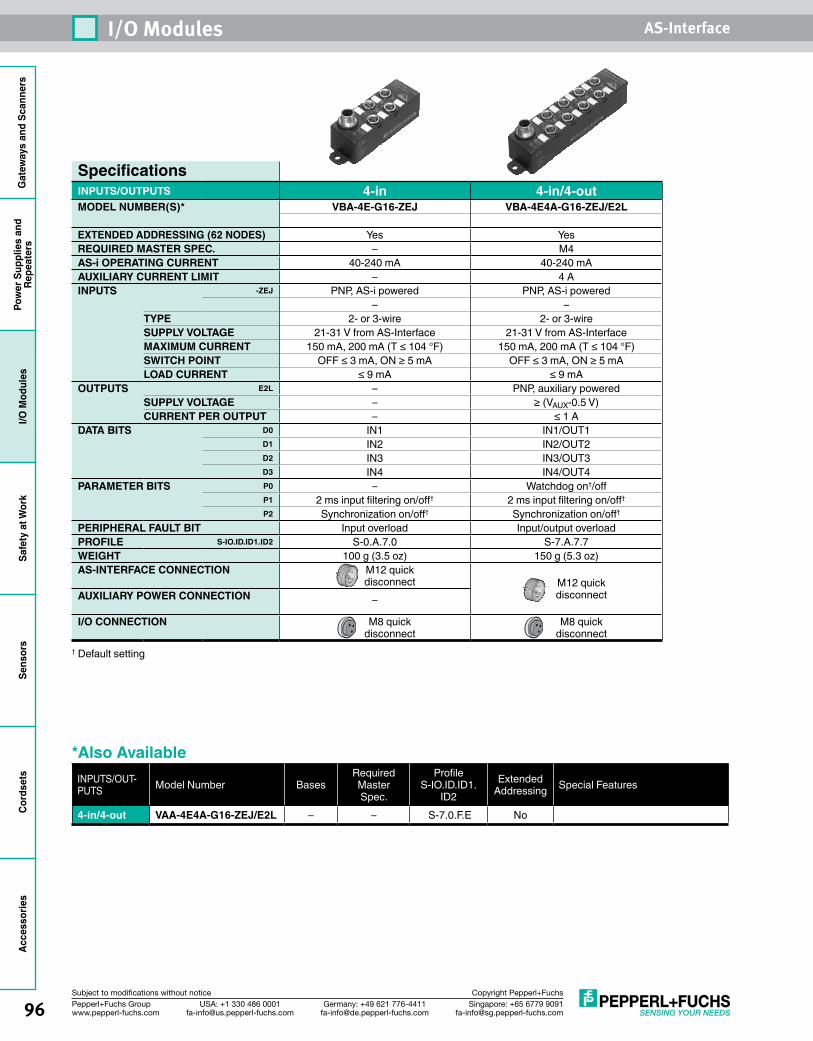
Gat
eway
s an
d Sc
anne
rsPo
wer
Sup
plie
s an
dRe
peat
ers
I/O M
odul
esSa
fety
at W
ork
Sens
ors
Cord
sets
Acce
ssor
ies
96 Singapore: +65 6779 [email protected]
USA: +1 330 486 [email protected]
Germany: +49 621 [email protected]
Pepperl+Fuchs Groupwww.pepperl-fuchs.com
Subject to modifications without notice Copyright Pepperl+Fuchs
I/O Modules AS-Interface
SpecificationsINPUTS/OUTPUTS 4-in 4-in/4-outMODEL NUMBER(S)* VBA-4E-G16-ZEJ VBA-4E4A-G16-ZEJ/E2L
EXTENDED ADDRESSING (62 NODES) Yes YesREQUIRED MASTER SPEC. – M4AS-i OPERATING CURRENT 40-240 mA 40-240 mAAUXILIARY CURRENT LIMIT – 4 AINPUTS -ZEJ PNP, AS-i powered PNP, AS-i powered
– –TYPE 2- or 3-wire 2- or 3-wireSUPPLY VOLTAGE 21-31 V from AS-Interface 21-31 V from AS-InterfaceMAXIMUM CURRENT 150 mA, 200 mA (T ≤ 104 °F) 150 mA, 200 mA (T ≤ 104 °F)SWITCH POINT OFF ≤ 3 mA, ON ≥ 5 mA OFF ≤ 3 mA, ON ≥ 5 mALOAD CURRENT ≤ 9 mA ≤ 9 mA
OUTPUTS E2L – PNP, auxiliary poweredSUPPLY VOLTAGE – ≥ (VAUX-0.5 V)CURRENT PER OUTPUT – ≤ 1 A
DATA BITS D0 IN1 IN1/OUT1D1 IN2 IN2/OUT2D2 IN3 IN3/OUT3D3 IN4 IN4/OUT4
PARAMETER BITS P0 – Watchdog on†/offP1 2 ms input filtering on/off† 2 ms input filtering on/off†
P2 Synchronization on/off† Synchronization on/off†
PERIPHERAL FAULT BIT Input overload Input/output overloadPROFILE S-IO.ID.ID1.ID2 S-0.A.7.0 S-7.A.7.7WEIGHT 100 g (3.5 oz) 150 g (5.3 oz)AS-INTERFACE CONNECTION M12 quick
disconnect M12 quick disconnectAUXILIARY POWER CONNECTION –
I/O CONNECTION M8 quick disconnect
M8 quick disconnect
† Default setting
*Also AvailableINPUTS/OUT-PUTS Model Number Bases
Required Master Spec.
Profile S-IO.ID.ID1.
ID2Extended
Addressing Special Features
4-in/4-out VAA-4E4A-G16-ZEJ/E2L – – S-7.0.F.E No
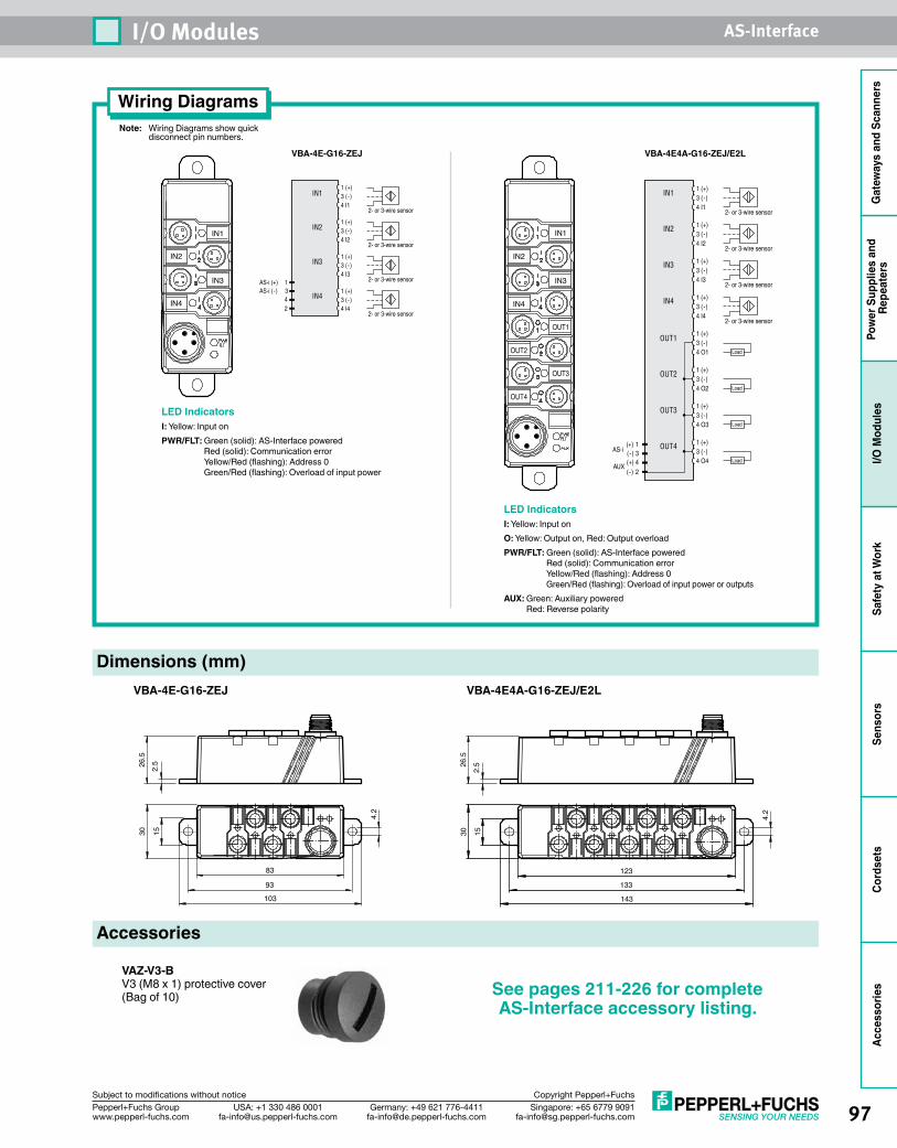
97Singapore: +65 6779 [email protected]
USA: +1 330 486 [email protected]
Germany: +49 621 [email protected]
Pepperl+Fuchs Groupwww.pepperl-fuchs.com
Subject to modifications without notice Copyright Pepperl+Fuchs
I/O Modules AS-Interface
Gat
eway
s an
d Sc
anne
rsPo
wer
Sup
plie
s an
d Re
peat
ers
I/O M
odul
esSa
fety
at W
ork
Sens
ors
Cord
sets
Acce
ssor
ies
Note: Wiring Diagrams show quick disconnect pin numbers.
Wiring Diagrams
LED IndicatorsI: Yellow: Input onPWR/FLT: Green (solid): AS-Interface powered
Red (solid): Communication error Yellow/Red (flashing): Address 0 Green/Red (flashing): Overload of input power
1 (+)3 (-)4 I1
2- or 3-wire sensor
1 (+)3 (-)4 I2
2- or 3-wire sensor
1 (+)3 (-)4 I3
2- or 3-wire sensor
1 (+)3 (-)4 I4
2- or 3-wire sensor
IN1
IN2
IN3
IN4
AS-i (+) 1AS-i (-) 3 4 2
VBA-4E-G16-ZEJ
Dimensions (mm)
Accessories
VAZ-V3-BV3 (M8 x 1) protective cover (Bag of 10)
IN4
IN2
IN3
IN1 IN1
IN3
OUT1
OUT3
IN2
IN4
OUT2
OUT4
1 (+)3 (-)4 O1
2- or 3-wire sensor
1 (+)3 (-)4 O2
2- or 3-wire sensor
1 (+)3 (-)4 O3
2- or 3-wire sensor
1 (+)3 (-)4 O4
1 (+)3 (-)4 I2
1 (+)3 (-)4 I3
1 (+)3 (-)4 I1
1 (+)3 (-)4 I4
2- or 3-wire sensor
OUT1
OUT2
OUT3
OUT4
IN1
IN2
IN3
IN4
Load
Load
Load
Load
(+) 1(-) 3(+) 4(-) 2
AUX
AS-i
VBA-4E4A-G16-ZEJ/E2L
LED IndicatorsI: Yellow: Input onO: Yellow: Output on, Red: Output overloadPWR/FLT: Green (solid): AS-Interface powered
Red (solid): Communication error Yellow/Red (flashing): Address 0 Green/Red (flashing): Overload of input power or outputs
AUX: Green: Auxiliary powered Red: Reverse polarity
1530
83
93
103
4.2
2.526
.5
123
133
143
1530
4.2
2.526
.5
VBA-4E-G16-ZEJ VBA-4E4A-G16-ZEJ/E2L
See pages 211-226 for complete AS-Interface accessory listing.
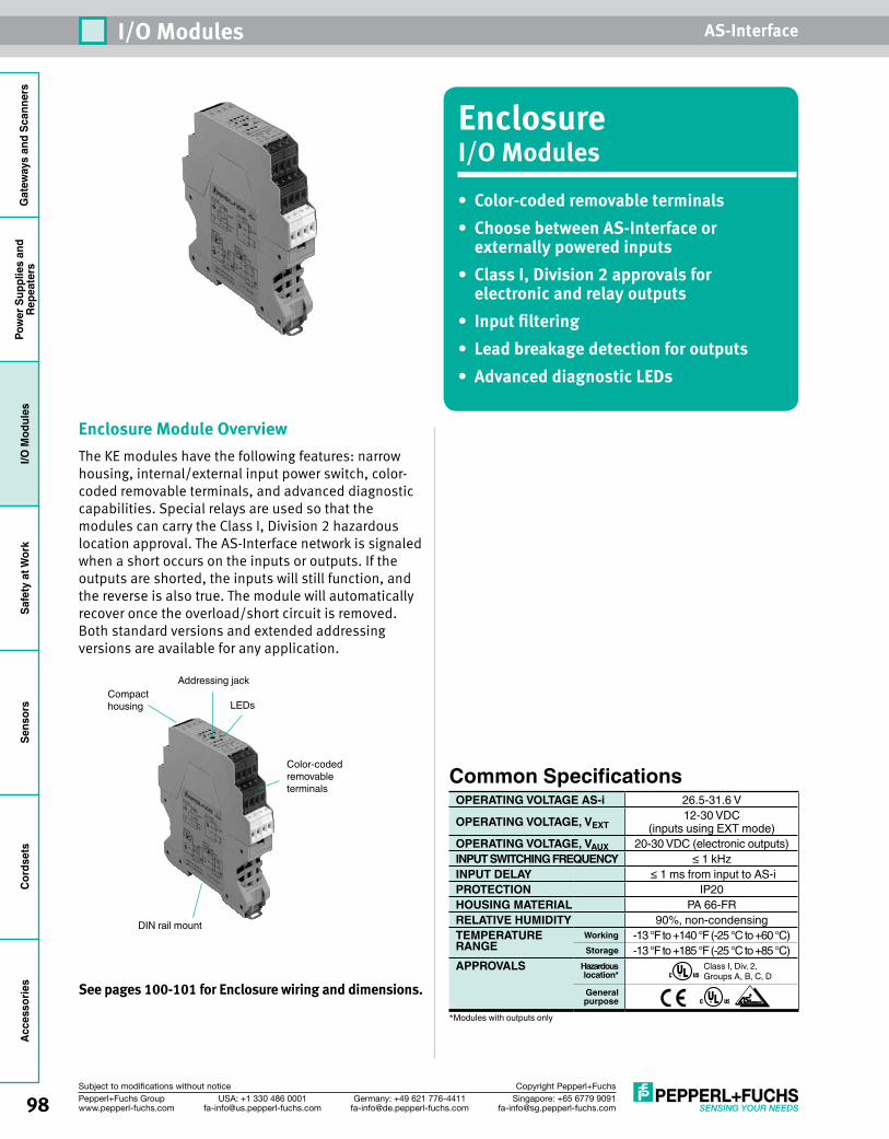
Gat
eway
s an
d Sc
anne
rsPo
wer
Sup
plie
s an
dRe
peat
ers
I/O M
odul
esSa
fety
at W
ork
Sens
ors
Cord
sets
Acce
ssor
ies
98 Singapore: +65 6779 [email protected]
USA: +1 330 486 [email protected]
Germany: +49 621 [email protected]
Pepperl+Fuchs Groupwww.pepperl-fuchs.com
Subject to modifications without notice Copyright Pepperl+Fuchs
I/O Modules AS-Interface
EnclosureI/O Modules• Color-coded removable terminals• Choose between AS-Interface or
externally powered inputs• Class I, Division 2 approvals for
electronic and relay outputs• Input filtering• Lead breakage detection for outputs• Advanced diagnostic LEDs
Enclosure Module OverviewThe KE modules have the following features: narrow housing, internal/external input power switch, color-coded removable terminals, and advanced diagnostic capabilities. Special relays are used so that the modules can carry the Class I, Division 2 hazardous location approval. The AS-Interface network is signaled when a short occurs on the inputs or outputs. If the outputs are shorted, the inputs will still function, and the reverse is also true. The module will automatically recover once the overload/short circuit is removed. Both standard versions and extended addressing versions are available for any application.
See pages 100-101 for Enclosure wiring and dimensions.
DIN rail mount
Color-coded removableterminals
Compacthousing
Addressing jack
LEDs
Common SpecificationsOPERATING VOLTAGE AS-i 26.5-31.6 V
OPERATING VOLTAGE, VEXT12-30 VDC
(inputs using EXT mode)OPERATING VOLTAGE, VAUX 20-30 VDC (electronic outputs)INPUT SWITCHING FREQUENCY ≤ 1 kHzINPUT DELAY ≤ 1 ms from input to AS-iPROTECTION IP20HOUSING MATERIAL PA 66-FRRELATIVE HUMIDITY 90%, non-condensingTEMPERATURE Working -13 °F to +140 °F (-25 °C to +60 °C)RANGE Storage -13 °F to +185 °F (-25 °C to +85 °C)APPROVALS Hazardous
location*Class I, Div. 2, Groups A, B, C, D
General purpose
*Modules with outputs only
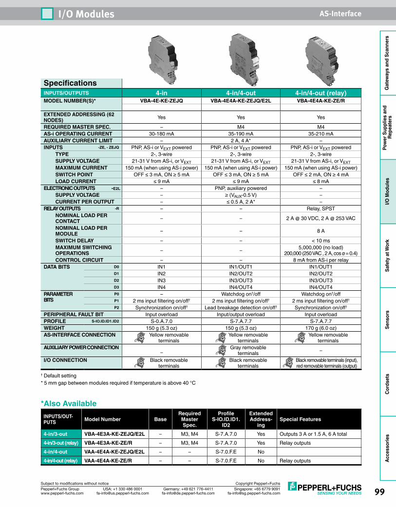
99Singapore: +65 6779 [email protected]
USA: +1 330 486 [email protected]
Germany: +49 621 [email protected]
Pepperl+Fuchs Groupwww.pepperl-fuchs.com
Subject to modifications without notice Copyright Pepperl+Fuchs
I/O Modules AS-Interface
Gat
eway
s an
d Sc
anne
rsPo
wer
Sup
plie
s an
d Re
peat
ers
I/O M
odul
esSa
fety
at W
ork
Sens
ors
Cord
sets
Acce
ssor
ies
SpecificationsINPUTS/OUTPUTS 4-in 4-in/4-out 4-in/4-out (relay)MODEL NUMBER(S)* VBA-4E-KE-ZEJQ VBA-4E4A-KE-ZEJQ/E2L VBA-4E4A-KE-ZE/R
EXTENDED ADDRESSING (62 NODES) Yes Yes Yes
REQUIRED MASTER SPEC. – M4 M4AS-i OPERATING CURRENT 30-180 mA 35-190 mA 35-210 mAAUXILIARY CURRENT LIMIT – 2 A, 4 A* –INPUTS -ZE, - ZEJQ PNP, AS-i or VEXT powered PNP, AS-i or VEXT powered PNP, AS-i or VEXT powered
TYPE 2-, 3-wire 2-, 3-wire 2-, 3-wireSUPPLY VOLTAGE 21-31 V from AS-i, or VEXT 21-31 V from AS-i, or VEXT 21-31 V from AS-i, or VEXTMAXIMUM CURRENT 150 mA (when using AS-i power) 150 mA (when using AS-i power) 150 mA (when using AS-i power)SWITCH POINT OFF ≤ 3 mA, ON ≥ 5 mA OFF ≤ 3 mA, ON ≥ 5 mA OFF ≤ 2 mA, ON ≥ 4 mALOAD CURRENT ≤ 9 mA ≤ 9 mA ≤ 8 mA
ELECTRONIC OUTPUTS -E2L – PNP, auxiliary powered –SUPPLY VOLTAGE – ≥ (VAUX-0.5 V) –CURRENT PER OUTPUT – ≤ 0.5 A, 2 A* –
RELAY OUTPUTS -R – – Relay, SPSTNOMINAL LOAD PER CONTACT – – 2 A @ 30 VDC, 2 A @ 253 VAC
NOMINAL LOAD PER MODULE – – 8 A
SWITCH DELAY – – < 10 msMAXIMUM SWITCHING OPERATIONS – – 5,000,000 (no load)
200,000 (250 VAC , 2 A, cos ø = 0.4)CONTROL CIRCUIT – – 8 mA from AS-i per relay
DATA BITS D0 IN1 IN1/OUT1 IN1/OUT1D1 IN2 IN2/OUT2 IN2/OUT2D2 IN3 IN3/OUT3 IN3/OUT3D3 IN4 IN4/OUT4 IN4/OUT4
PARAMETER BITS
P0 – Watchdog on†/off Watchdog on†/offP1 2 ms input filtering on/off† 2 ms input filtering on/off† 2 ms input filtering on/off†
P2 Synchronization on/off† Lead breakage detection on/off† Synchronization on/off†
PERIPHERAL FAULT BIT Input overload Input/output overload Input overloadPROFILE S-IO.ID.ID1.ID2 S-0.A.7.0 S-7.A.7.7 S-7.A.7.7WEIGHT 150 g (5.3 oz) 150 g (5.3 oz) 170 g (6.0 oz)AS-INTERFACE CONNECTION Yellow removable
terminalsYellow removable
terminalsYellow removable
terminalsAUXILIARY POWER CONNECTION
–Gray removable
terminals –
I/O CONNECTION Black removable terminals
Black removable terminals
Black removable terminals (input), red removable terminals (output)
† Default setting* 5 mm gap between modules required if temperature is above 40 °C
*Also AvailableINPUTS/OUT-PUTS Model Number Base
Required Master Spec.
Profile S-IO.ID.ID1.
ID2
Extended Address-
ingSpecial Features
4-in/3-out VBA-4E3A-KE-ZEJQ/E2L – M3, M4 S-7.A.7.0 Yes Outputs 3 A or 1.5 A, 6 A total4-in/3-out (relay) VBA-4E3A-KE-ZE/R – M3, M4 S-7.A.7.0 Yes Relay outputs4-in/4-out VAA-4E4A-KE-ZEJQ/E2L – – S-7.0.F.E No4-in/4-out (relay) VAA-4E4A-KE-ZE/R – – S-7.0.F.E No Relay outputs
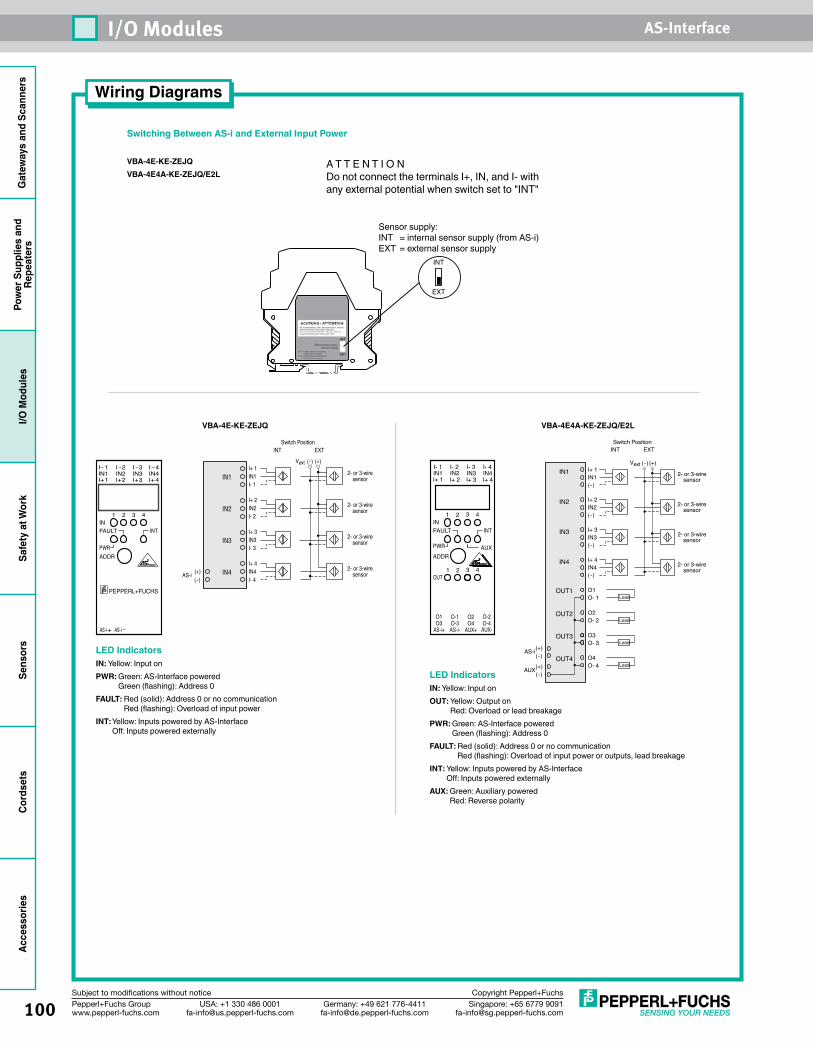
Gat
eway
s an
d Sc
anne
rsPo
wer
Sup
plie
s an
dRe
peat
ers
I/O M
odul
esSa
fety
at W
ork
Sens
ors
Cord
sets
Acce
ssor
ies
100 Singapore: +65 6779 [email protected]
USA: +1 330 486 [email protected]
Germany: +49 621 [email protected]
Pepperl+Fuchs Groupwww.pepperl-fuchs.com
Subject to modifications without notice Copyright Pepperl+Fuchs
I/O Modules AS-Interface
A T T E N T I O NDo not connect the terminals I+, IN, and I- with any external potential when switch set to "INT"
Sensor supply:INT = internal sensor supply (from AS-i)EXT = external sensor supply
EXT
INT
Wiring Diagrams
VBA-4E-KE-ZEJQ
I+ 1IN1I- 1
2- or 3-wiresensor
2- or 3-wiresensor
2- or 3-wiresensor
2- or 3-wiresensor
Switch PositionINT EXT
IN1
I+ 2IN2I- 2
IN2
I+ 3IN3I- 3
IN3
I+ 4IN4I- 4
IN4
(+)Vext (-)
(+)(-)
AS-i
IN1I I I I
I I I I+
+
+ + +
1 2 3 4
2 3 41IN2 IN3 IN4
1 2 3 4INFAULT INT
PWRADDR
AS-i AS-i
PEPPERL+FUCHS
LED IndicatorsIN: Yellow: Input onPWR: Green: AS-Interface powered
Green (flashing): Address 0FAULT: Red (solid): Address 0 or no communication
Red (flashing): Overload of input powerINT: Yellow: Inputs powered by AS-Interface
Off: Inputs powered externally
VBA-4E4A-KE-ZEJQ/E2L
IN1
IN2
IN3
O1O- 1
O2O- 2
O3O- 3
IN4
OUT1
OUT2
OUT3
Load
Load
Load
I+ 1IN1(-)
I+ 2IN2(-)
I+ 3IN3(-)
I+ 4IN4(-)
Switch PositionINT EXT
(+)(-)
AUX
O4O- 4
OUT4Load
(+)(-)
AS-i
2- or 3-wiresensor
2- or 3-wiresensor
2- or 3-wiresensor
2- or 3-wiresensor
(+)Vext (-)
O1O3
O-1O-3
O2 O-2O4 O-4
LED IndicatorsIN: Yellow: Input onOUT: Yellow: Output on
Red: Overload or lead breakagePWR: Green: AS-Interface powered
Green (flashing): Address 0FAULT: Red (solid): Address 0 or no communication
Red (flashing): Overload of input power or outputs, lead breakageINT: Yellow: Inputs powered by AS-Interface
Off: Inputs powered externallyAUX: Green: Auxiliary powered
Red: Reverse polarity
Switching Between AS-i and External Input Power
VBA-4E-KE-ZEJQVBA-4E4A-KE-ZEJQ/E2L
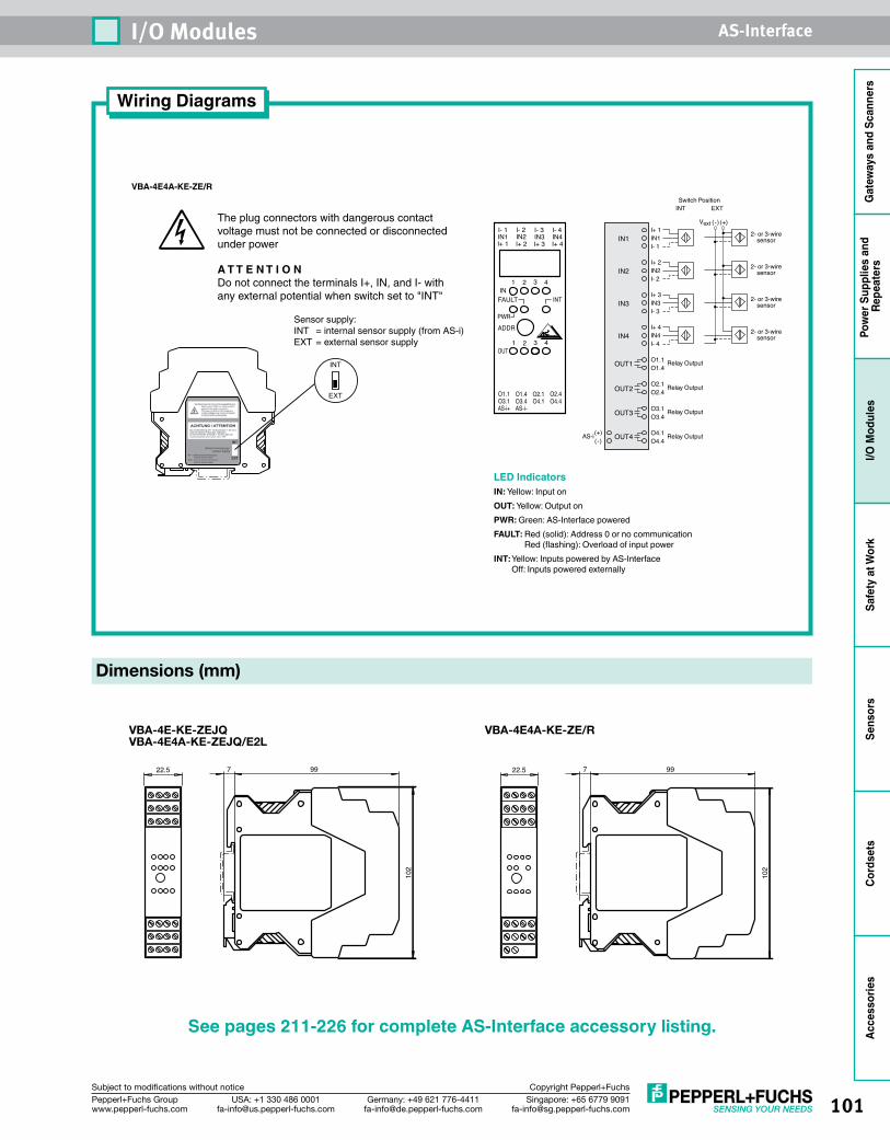
101Singapore: +65 6779 [email protected]
USA: +1 330 486 [email protected]
Germany: +49 621 [email protected]
Pepperl+Fuchs Groupwww.pepperl-fuchs.com
Subject to modifications without notice Copyright Pepperl+Fuchs
I/O Modules AS-Interface
Gat
eway
s an
d Sc
anne
rsPo
wer
Sup
plie
s an
d Re
peat
ers
I/O M
odul
esSa
fety
at W
ork
Sens
ors
Cord
sets
Acce
ssor
ies
22.5 99710
2
Wiring Diagrams
I- 1IN1I+ 1
I- 2IN2I+ 2
I- 3IN3I+ 3
I- 4IN4I+ 4
1
1
2
2
3
3 4
4IN
FAULT INT
PWRADDR
OUT
O1.1O3.1AS-i+
O1.4O3.4AS-i-
O2.1 O2.4O4.1 O4.4
IN1
IN2
IN3
IN4
OUT1
OUT2
OUT3
OUT4
I+ 1IN1I- 1
I+ 2IN2I- 2
I+ 3IN3I- 3
I+ 4IN4
O1.1O1.4
O2.1O2.4
O3.1O3.4
O4.1O4.4
I- 4
Relay Output
Relay Output
Relay Output
Relay Output(+)(-)
AS-i
Switch PositionINT EXT
2- or 3-wiresensor
2- or 3-wiresensor
2- or 3-wiresensor
2- or 3-wiresensor
(+)Vext (-)
VBA-4E4A-KE-ZE/R
LED IndicatorsIN: Yellow: Input onOUT: Yellow: Output onPWR: Green: AS-Interface poweredFAULT: Red (solid): Address 0 or no communication
Red (flashing): Overload of input powerINT: Yellow: Inputs powered by AS-Interface
Off: Inputs powered externally
Dimensions (mm)
22.5 997
102
VBA-4E-KE-ZEJQVBA-4E4A-KE-ZEJQ/E2L
VBA-4E4A-KE-ZE/R
See pages 211-226 for complete AS-Interface accessory listing.
The plug connectors with dangerous contact voltage must not be connected or disconnected under power
A T T E N T I O NDo not connect the terminals I+, IN, and I- with any external potential when switch set to "INT"
Sensor supply:INT = internal sensor supply (from AS-i)EXT = external sensor supply
EXT
INT
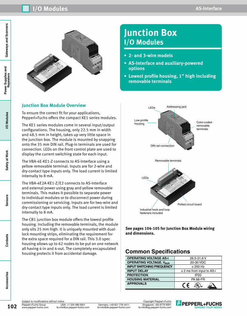
Gat
eway
s an
d Sc
anne
rsPo
wer
Sup
plie
s an
dRe
peat
ers
I/O M
odul
esSa
fety
at W
ork
Sens
ors
Cord
sets
Acce
ssor
ies
102 Singapore: +65 6779 [email protected]
USA: +1 330 486 [email protected]
Germany: +49 621 [email protected]
Pepperl+Fuchs Groupwww.pepperl-fuchs.com
Subject to modifications without notice Copyright Pepperl+Fuchs
I/O Modules AS-Interface
Junction BoxI/O Modules• 2- and 3-wire models• AS-Interface and auxiliary-powered
options• Lowest profile housing, 1” high including
removable terminals
Junction Box Module OverviewTo ensure the correct fit for your applications, Pepperl+Fuchs offers the compact KE1 series modules.
The KE1 series modules come in several input/output configurations. The housing, only 22.5 mm in width and 48.5 mm in height, takes up very little space in the junction box. The module is mounted by snapping onto the 35 mm DIN rail. Plug-in terminals are used for connection. LEDs on the front control plate are used to display the current switching state for each input.
The VBA-4E-KE1-Z connects to AS-Interface using a yellow removable terminal. Inputs are for 2-wire and dry-contact type inputs only. The load current is limited internally to 8 mA.
The VBA-4E2A-KE1-Z/E2 connects to AS-Interface and external power using gray and yellow removable terminals. This makes it possible to separate power to individual modules or to disconnect power during commissioning or servicing. Inputs are for two-wire and dry-contact type inputs only. The load current is limited internally to 8 mA.
The CB1 junction box module offers the lowest profile housing. Including the removable terminals, the module only sits 25 mm high. It is uniquely mounted with dual-lock mounting strips, eliminating the requirement for the extra space required for a DIN rail. This 3.0 spec housing allows up to 62 nodes to be put on one network all having 4-in and 4-out. The completely encapsulated housing protects it from accidental damage.
See pages 104-105 for Junction Box Module wiring and dimensions.
DIN rail connection
Color-coded removableterminals
Addressing jackLEDs
Low-profilehousing
Common SpecificationsOPERATING VOLTAGE AS-i 26.5-31.6 VOPERATING VOLTAGE, VAUX 20-30 VDCINPUT SWITCHING FREQUENCY ≤ 250 HzINPUT DELAY ≤ 2 ms from input to AS-iPROTECTION IP20HOUSING MATERIAL PA 66-FRAPPROVALS
Removable terminals
Potted circuit board
Industrial hook and loop fasteners included
LEDs
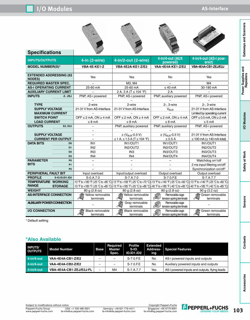
103Singapore: +65 6779 [email protected]
USA: +1 330 486 [email protected]
Germany: +49 621 [email protected]
Pepperl+Fuchs Groupwww.pepperl-fuchs.com
Subject to modifications without notice Copyright Pepperl+Fuchs
I/O Modules AS-Interface
Gat
eway
s an
d Sc
anne
rsPo
wer
Sup
plie
s an
d Re
peat
ers
I/O M
odul
esSa
fety
at W
ork
Sens
ors
Cord
sets
Acce
ssor
ies
SpecificationsINPUTS/OUTPUTS 4-in (2-wire) 4-in/2-out (2-wire) 4-in/4-out (AUX
powered)4-in/4-out (AS-i pow-
ered)MODEL NUMBER(S)* VBA-4E-KE1-Z VBA-4E2A-KE1-Z/E2 VAA-4E4A-KE1-Z/E2 VBA-4E4A-CB1-ZEJ/E2J
EXTENDED ADDRESSING (62 NODES) Yes Yes No Yes
REQUIRED MASTER SPEC. – M3, M4 – M4AS-i OPERATING CURRENT 25-60 mA 25-60 mA ≤ 40 mA 30-180 mAAUXILIARY CURRENT LIMIT – 2 A, 3 A (T ≤ 104 °F) 2 A –INPUTS -Z, -ZEJ PNP, AS-i powered PNP, AS-i powered PNP, auxiliary powered PNP, AS-i powered
– – – –TYPE 2-wire 2-wire 2-, 3-wire 2-, 3-wireSUPPLY VOLTAGE 21-31 V from AS-Interface 21-31 V from AS-Interface VAUX 21-31 V from AS-InterfaceMAXIMUM CURRENT – – – Limited by operating currentSWITCH POINT OFF ≤ 2 mA, ON ≥ 4 mA OFF ≤ 2 mA, ON ≥ 4 mA OFF ≤ 2 mA, ON ≥ 4 mA OFF ≤ 0.5 mA, ON ≥ 2 mALOAD CURRENT ≤ 8 mA ≤ 8 mA ≤ 8 mA ≤ 5 mA
OUTPUTS E2, E2J – PNP, auxiliary powered PNP, auxiliary powered PNP, AS-i powered– – – –
SUPPLY VOLTAGE – ≥ (VAUX-0.5 V) ≥ (VAUX-0.5 V) 21-31 V from AS-InterfaceCURRENT PER OUTPUT – ≤ 1 A, ≤ 1.5 A (T ≤ 104 °F) ≤ 0.5 A ≤ 100 mA (≤ 140 mA total)
DATA BITS D0 IN1 IN1/OUT1 IN1/OUT1 IN1/OUT1D1 IN2 IN2/OUT2 IN2/OUT2 IN2/OUT2D2 IN3 IN3 IN3/OUT3 IN3/OUT3D3 IN4 IN4 IN4/OUT4 IN4/OUT4
PARAMETER BITS
P0 – – – Watchdog on†/offP1 – – – 2 ms input filtering on/off†
P2 – – – Synchronization on/off†
PERIPHERAL FAULT BIT Input overload Input/output overload Output overload Output overloadPROFILE S-IO.ID.ID1.ID2 S-0.A.7.0 S-7.A.7.0 S-7.0.F.E S-7.A.7.7TEMPERATURE RANGE
WORKING -13 °F to +185 °F (-25 °C to +85 °C) -13 °F to +158 °F (-25 °C to +70 °C) -13 °F to +140 °F (-25 °C to +60 °C) -13 °F to +140 °F (-25 °C to +60 °C)STORAGE -13 °F to +185 °F (-25 °C to +85 °C) -13 °F to +185 °F (-25 °C to +85 °C) -40 °F to +185 °F (-40 °C to +85 °C) -40 °F to +185 °F (-40 °C to +85 °C)
WEIGHT 80 g (2.8 oz) 80 g (2.8 oz) 80 g (2.8 oz) 90 g (3.2 oz)AS-INTERFACE CONNECTION Yellow removable
terminalsYellow removable
terminalsRemovable cage
tension spring terminalsGreen removable
terminalsAUXILIARY POWER CONNECTION – Gray removable
terminalsRemovable cage
tension spring terminals –
I/O CONNECTION Black removable terminals
Black removable terminals
Removable cage tension spring terminals
Green removable terminals
† Default setting
*Also AvailableINPUTS/OUTPUTS Model Number Base
Required Master Spec.
Profile S-IO.
ID.ID1.ID2
Extended Address-
ingSpecial Features
4-in/4-out VAA-4E4A-CB1-Z/E2 – – S-7.0.F.E No AS-i powered inputs and outputs4-in/4-out VAA-4E4A-CB2-Z/E2 – – S-7.0.F.E No Auxiliary powered inputs and outputs4-in/4-out VBA-4E4A-CB1-ZEJ/E2J-FL – M4 S-7.A.7.7 Yes AS-i powered inputs and outputs, flying leads
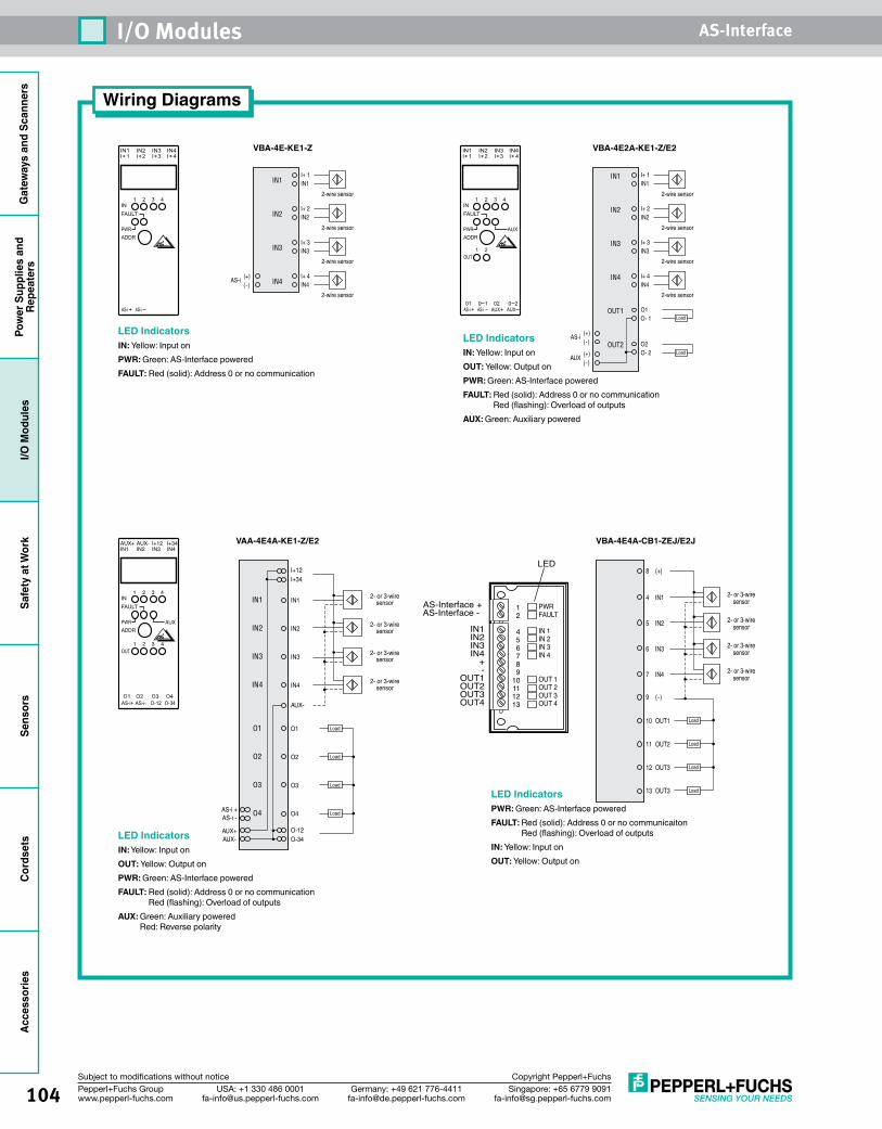
Gat
eway
s an
d Sc
anne
rsPo
wer
Sup
plie
s an
dRe
peat
ers
I/O M
odul
esSa
fety
at W
ork
Sens
ors
Cord
sets
Acce
ssor
ies
104 Singapore: +65 6779 [email protected]
USA: +1 330 486 [email protected]
Germany: +49 621 [email protected]
Pepperl+Fuchs Groupwww.pepperl-fuchs.com
Subject to modifications without notice Copyright Pepperl+Fuchs
I/O Modules AS-Interface
Wiring Diagrams
VBA-4E-KE1-Z
I+ 1IN1
2-wire sensor
2-wire sensor
2-wire sensor
2-wire sensor
IN1
I+ 2IN2IN2
I+ 3IN3IN3
I+ 4IN4IN4
(+)(-)
AS-i
VBA-4E2A-KE1-Z/E2
I+ 1IN1
2-wire sensor
2-wire sensor
2-wire sensor
2-wire sensor
IN1
I+ 2IN2
IN2
I+ 3IN3
IN3
I+ 4IN4
IN4
OUT1
OUT2
O1O- 1
O2O- 2
Load
Load(+)(-)
AUX
(+)(-)
AS-i
VAA-4E4A-KE1-Z/E2
IN1IN1
IN2IN2
IN3IN3
IN4
AUX-
IN4
I+12I+34
O1O1
O2O2
O3O3
O4
O-12O-34
O4
Load
Load
Load
Load
AUX-AUX+
2- or 3-wiresensor
2- or 3-wiresensor
2- or 3-wiresensor
2- or 3-wiresensor
AS-i -AS-i +
LED IndicatorsIN: Yellow: Input onPWR: Green: AS-Interface poweredFAULT: Red (solid): Address 0 or no communication
AUX+IN1 IN2 IN3 IN4
AUX- I+12 I+34
1
1
2
2 3 4
3 4INFAULT
AUXPWRADDR
OUT
O1
AS-i+ AS-i-
O2 O3
O-12 O-34
O4
LED IndicatorsIN: Yellow: Input onOUT: Yellow: Output onPWR: Green: AS-Interface poweredFAULT: Red (solid): Address 0 or no communication
Red (flashing): Overload of outputsAUX: Green: Auxiliary powered
LED IndicatorsIN: Yellow: Input onOUT: Yellow: Output onPWR: Green: AS-Interface poweredFAULT: Red (solid): Address 0 or no communication
Red (flashing): Overload of outputsAUX: Green: Auxiliary powered
Red: Reverse polarity
LED IndicatorsPWR: Green: AS-Interface poweredFAULT: Red (solid): Address 0 or no communicaiton
Red (flashing): Overload of outputsIN: Yellow: Input onOUT: Yellow: Output on
4 IN1
5 IN2
6 IN3
7 IN4
9 (-)
10 OUT1
11 OUT2
12 OUT3
13 OUT3
8 (+)
Load
Load
Load
Load
2- or 3-wiresensor
2- or 3-wiresensor
2- or 3-wiresensor
2- or 3-wiresensor
VBA-4E4A-CB1-ZEJ/E2J
AS-Interface + AS-Interface -
IN1IN2IN3IN4
+-
OUT1OUT2OUT3OUT4
LED
12
456789
10111213
PWRFAULT
IN 1IN 2IN 3IN 4
OUT 1OUT 2OUT 3OUT 4
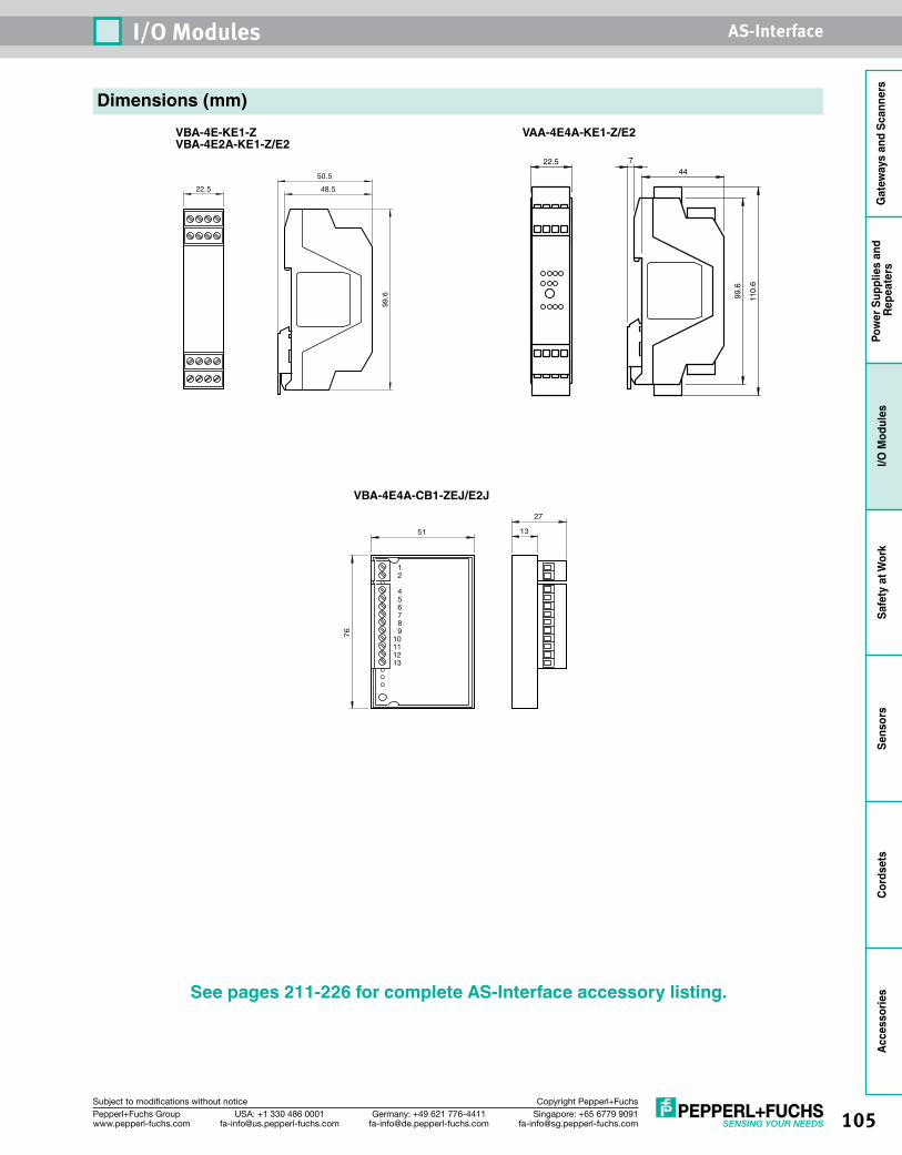
105Singapore: +65 6779 [email protected]
USA: +1 330 486 [email protected]
Germany: +49 621 [email protected]
Pepperl+Fuchs Groupwww.pepperl-fuchs.com
Subject to modifications without notice Copyright Pepperl+Fuchs
I/O Modules AS-Interface
Gat
eway
s an
d Sc
anne
rsPo
wer
Sup
plie
s an
d Re
peat
ers
I/O M
odul
esSa
fety
at W
ork
Sens
ors
Cord
sets
Acce
ssor
ies
VBA-4E-KE1-ZVBA-4E2A-KE1-Z/E2
99.6
48.5
50.5
22.5
Dimensions (mm)VAA-4E4A-KE1-Z/E2
722.5
99.6
44
110.
6
See pages 211-226 for complete AS-Interface accessory listing.
VBA-4E4A-CB1-ZEJ/E2J
51
76
13
27
12
456789
10111213
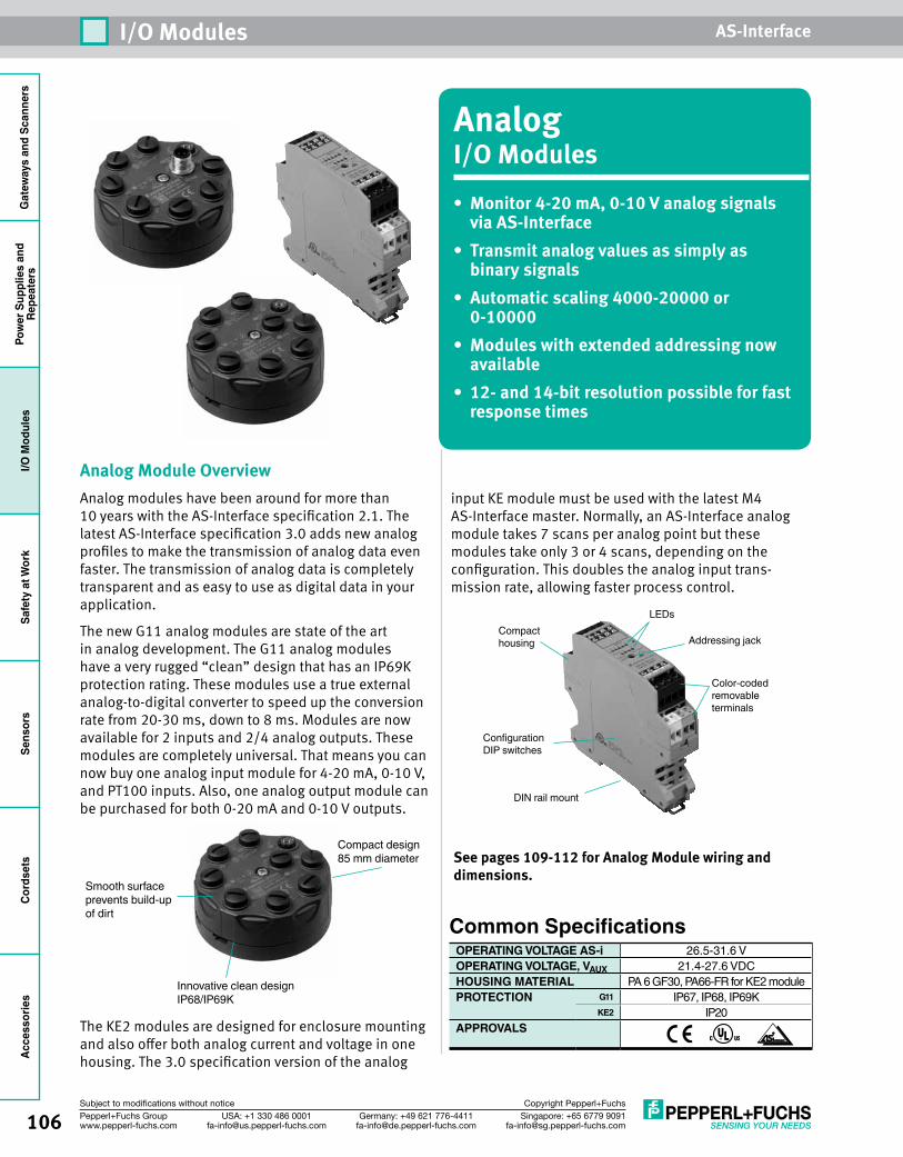
Gat
eway
s an
d Sc
anne
rsPo
wer
Sup
plie
s an
dRe
peat
ers
I/O M
odul
esSa
fety
at W
ork
Sens
ors
Cord
sets
Acce
ssor
ies
106 Singapore: +65 6779 [email protected]
USA: +1 330 486 [email protected]
Germany: +49 621 [email protected]
Pepperl+Fuchs Groupwww.pepperl-fuchs.com
Subject to modifications without notice Copyright Pepperl+Fuchs
I/O Modules AS-Interface
AnalogI/O Modules• Monitor 4-20 mA, 0-10 V analog signals
via AS-Interface • Transmit analog values as simply as
binary signals• Automatic scaling 4000-20000 or
0-10000• Modules with extended addressing now
available• 12- and 14-bit resolution possible for fast
response times
Analog Module OverviewAnalog modules have been around for more than 10 years with the AS-Interface specification 2.1. The latest AS-Interface specification 3.0 adds new analog profiles to make the transmission of analog data even faster. The transmission of analog data is completely transparent and as easy to use as digital data in your application.
The new G11 analog modules are state of the art in analog development. The G11 analog modules have a very rugged “clean” design that has an IP69K protection rating. These modules use a true external analog-to-digital converter to speed up the conversion rate from 20-30 ms, down to 8 ms. Modules are now available for 2 inputs and 2/4 analog outputs. These modules are completely universal. That means you can now buy one analog input module for 4-20 mA, 0-10 V, and PT100 inputs. Also, one analog output module can be purchased for both 0-20 mA and 0-10 V outputs.
See pages 109-112 for Analog Module wiring and dimensions.
DIN rail mount
Color-coded removableterminals
Compacthousing Addressing jack
LEDs
Configuration DIP switches
Common SpecificationsOPERATING VOLTAGE AS-i 26.5-31.6 VOPERATING VOLTAGE, VAUX 21.4-27.6 VDCHOUSING MATERIAL PA 6 GF30, PA66-FR for KE2 modulePROTECTION G11 IP67, IP68, IP69K
KE2 IP20APPROVALS
Smooth surface prevents build-up of dirt
Compact design85 mm diameter
Innovative clean design IP68/IP69K
The KE2 modules are designed for enclosure mounting and also offer both analog current and voltage in one housing. The 3.0 specification version of the analog
input KE module must be used with the latest M4 AS-Interface master. Normally, an AS-Interface analog module takes 7 scans per analog point but these modules take only 3 or 4 scans, depending on the configuration. This doubles the analog input trans-mission rate, allowing faster process control.
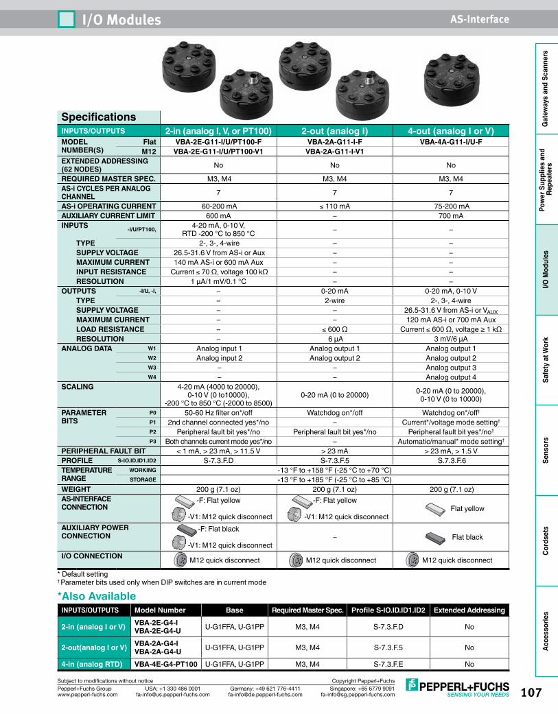
107Singapore: +65 6779 [email protected]
USA: +1 330 486 [email protected]
Germany: +49 621 [email protected]
Pepperl+Fuchs Groupwww.pepperl-fuchs.com
Subject to modifications without notice Copyright Pepperl+Fuchs
I/O Modules AS-Interface
Gat
eway
s an
d Sc
anne
rsPo
wer
Sup
plie
s an
d Re
peat
ers
I/O M
odul
esSa
fety
at W
ork
Sens
ors
Cord
sets
Acce
ssor
ies
SpecificationsINPUTS/OUTPUTS 2-in (analog I, V, or PT100) 2-out (analog I) 4-out (analog I or V)MODEL NUMBER(S)
Flat VBA-2E-G11-I/U/PT100-F VBA-2A-G11-I-F VBA-4A-G11-I/U-FM12 VBA-2E-G11-I/U/PT100-V1 VBA-2A-G11-I-V1
EXTENDED ADDRESSING (62 NODES) No No No
REQUIRED MASTER SPEC. M3, M4 M3, M4 M3, M4AS-i CYCLES PER ANALOG CHANNEL 7 7 7
AS-i OPERATING CURRENT 60-200 mA ≤ 110 mA 75-200 mAAUXILIARY CURRENT LIMIT 600 mA – 700 mAINPUTS -I/U/PT100, 4-20 mA, 0-10 V,
RTD -200 °C to 850 °C – –
TYPE 2-, 3-, 4-wire – –SUPPLY VOLTAGE 26.5-31.6 V from AS-i or Aux – –MAXIMUM CURRENT 140 mA AS-i or 600 mA Aux – –INPUT RESISTANCE Current ≤ 70 Ω, voltage 100 kΩ – –RESOLUTION 1 µA/1 mV/0.1 °C – –
OUTPUTS -I/U, -I, – 0-20 mA 0-20 mA, 0-10 VTYPE – 2-wire 2-, 3-, 4-wireSUPPLY VOLTAGE – – 26.5-31.6 V from AS-i or VAUXMAXIMUM CURRENT – – 120 mA AS-i or 700 mA AuxLOAD RESISTANCE – ≤ 600 Ω Current ≤ 600 Ω, voltage ≥ 1 kΩ RESOLUTION – 6 µA 3 mV/6 µA
ANALOG DATA W1 Analog input 1 Analog output 1 Analog output 1W2 Analog input 2 Analog output 2 Analog output 2W3 – – Analog output 3W4 – – Analog output 4
SCALING 4-20 mA (4000 to 20000), 0-10 V (0 to10000),
-200 °C to 850 °C (-2000 to 8500) 0-20 mA (0 to 20000) 0-20 mA (0 to 20000),
0-10 V (0 to 10000)
PARAMETER BITS
P0 50-60 Hz filter on*/off Watchdog on*/off Watchdog on*/off†
P1 2nd channel connected yes*/no – Current*/voltage mode setting†
P2 Peripheral fault bit yes*/no Peripheral fault bit yes*/no Peripheral fault bit yes*/no†
P3 Both channels current mode yes*/no – Automatic/manual* mode setting†
PERIPHERAL FAULT BIT < 1 mA, > 23 mA, > 11.5 V > 23 mA > 23 mA, > 1.5 V PROFILE S-IO.ID.ID1.ID2 S-7.3.F.D S-7.3.F.5 S.7.3.F.6TEMPERATURE RANGE
WORKING -13 °F to +158 °F (-25 °C to +70 °C)STORAGE -13 °F to +185 °F (-25 °C to +85 °C)
WEIGHT 200 g (7.1 oz) 200 g (7.1 oz) 200 g (7.1 oz)AS-INTERFACE CONNECTION
-F: Flat yellow
-V1: M12 quick disconnect
-F: Flat yellow
-V1: M12 quick disconnectFlat yellow
AUXILIARY POWER CONNECTION
-F: Flat black
-V1: M12 quick disconnect– Flat black
I/O CONNECTION M12 quick disconnect M12 quick disconnect M12 quick disconnect
* Default setting† Parameter bits used only when DIP switches are in current mode
*Also AvailableINPUTS/OUTPUTS Model Number Base Required Master Spec. Profile S-IO.ID.ID1.ID2 Extended Addressing
2-in (analog I or V) VBA-2E-G4-I VBA-2E-G4-U U-G1FFA, U-G1PP M3, M4 S-7.3.F.D No
2-out(analog I or V) VBA-2A-G4-I VBA-2A-G4-U U-G1FFA, U-G1PP M3, M4 S-7.3.F.5 No
4-in (analog RTD) VBA-4E-G4-PT100 U-G1FFA, U-G1PP M3, M4 S-7.3.F.E No
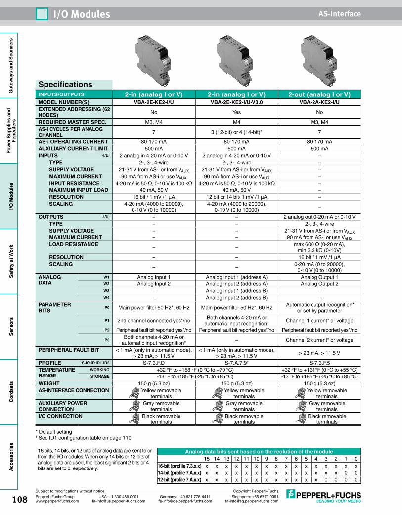
Gat
eway
s an
d Sc
anne
rsPo
wer
Sup
plie
s an
dRe
peat
ers
I/O M
odul
esSa
fety
at W
ork
Sens
ors
Cord
sets
Acce
ssor
ies
108 Singapore: +65 6779 [email protected]
USA: +1 330 486 [email protected]
Germany: +49 621 [email protected]
Pepperl+Fuchs Groupwww.pepperl-fuchs.com
Subject to modifications without notice Copyright Pepperl+Fuchs
I/O Modules AS-Interface
SpecificationsINPUTS/OUTPUTS 2-in (analog I or V) 2-in (analog I or V) 2-out (analog I or V)MODEL NUMBER(S) VBA-2E-KE2-I/U VBA-2E-KE2-I/U-V3.0 VBA-2A-KE2-I/UEXTENDED ADDRESSING (62 NODES) No Yes No
REQUIRED MASTER SPEC. M3, M4 M4 M3, M4AS-i CYCLES PER ANALOG CHANNEL 7 3 (12-bit) or 4 (14-bit)* 7
AS-i OPERATING CURRENT 80-170 mA 80-170 mA 80-170 mAAUXILIARY CURRENT LIMIT 500 mA 500 mA 500 mAINPUTS -I/U, 2 analog in 4-20 mA or 0-10 V 2 analog in 4-20 mA or 0-10 V –
TYPE 2-, 3-, 4-wire 2-, 3-, 4-wire –SUPPLY VOLTAGE 21-31 V from AS-i or from VAUX 21-31 V from AS-i or from VAUX –MAXIMUM CURRENT 90 mA from AS-i or use VAUX 90 mA from AS-i or use VAUX –INPUT RESISTANCE 4-20 mA is 50 Ω, 0-10 V is 100 kΩ 4-20 mA is 50 Ω, 0-10 V is 100 kΩ –MAXIMUM INPUT LOAD 40 mA, 50 V 40 mA, 50 V –RESOLUTION 16 bit / 1 mV /1 µA 12 bit or 14 bit/ 1 mV /1 μA –SCALING 4-20 mA (4000 to 20000),
0-10 V (0 to 10000)4-20 mA (4000 to 20000),
0-10 V (0 to 10000) –
OUTPUTS -I/U, – – 2 analog out 0-20 mA or 0-10 VTYPE – – 2-, 3-, 4-wireSUPPLY VOLTAGE – – 21-31 V from AS-i or from VAUXMAXIMUM CURRENT – – 90 mA from AS-i or use VAUXLOAD RESISTANCE – – max 600 Ω (0-20 mA),
min 3.3 kΩ (0-10V)RESOLUTION – – 16 bit / 1 mV /1 µASCALING – – 0-20 mA (0 to 20000),
0-10 V (0 to 10000)ANALOG DATA
W1 Analog Input 1 Analog Input 1 (address A) Analog Output 1W2 Analog Input 2 Analog Input 2 (address A) Analog Output 2W3 – Analog Input 1 (address B) –W4 – Analog Input 2 (address B) –
PARAMETER BITS P0 Main power filter 50 Hz*, 60 Hz Main power filter 50 Hz*, 60 Hz Automatic output recognition*
or set by parameterP1 2nd channel connected yes*/no Both channels 4-20 mA or
automatic input recognition* Channel 1 current* or voltageP2 Peripheral fault bit reported yes*/no Peripheral fault bit reported yes*/no Peripheral fault bit reported yes*/noP3 Both channels 4-20 mA or
automatic input recognition* – Channel 2 current* or voltage
PERIPHERAL FAULT BIT < 1 mA (only in automatic mode), > 23 mA, > 11.5 V
< 1 mA (only in automatic mode), > 23 mA, > 11.5 V > 23 mA, > 11.5 V
PROFILE S-IO.ID.ID1.ID2 S-7.3.F.D S-7.A.7.9† S-7.3.F.5TEMPERATURE RANGE
WORKING +32 °F to +158 °F (0 °C to +70 °C) +32 °F to +131°F (0 °C to +55 °C)STORAGE -13 °F to +185 °F (-25 °C to +85 °C) -13 °F to +185 °F (-25 °C to +85 °C)
WEIGHT 150 g (5.3 oz) 150 g (5.3 oz) 150 g (5.3 oz)AS-INTERFACE CONNECTION Yellow removable
terminalsYellow removable
terminalsYellow removable
terminalsAUXILIARY POWER CONNECTION
Gray removable terminals
Gray removable terminals
Gray removable terminals
I/O CONNECTION Black removable terminals
Black removable terminals
Black removable terminals
* Default setting† See ID1 configuration table on page 110
Analog data bits sent based on the reolution of the module15 14 13 12 11 10 9 8 7 6 5 4 3 2 1 0
16-bit (profile 7.3.x.x) x x x x x x x x x x x x x x x x14-bit (profile 7.A.x.x) x x x x x x x x x x x x x x 0 012-bit (profile 7.A.x.x) x x x x x x x x x x x x 0 0 0 0
16 bits, 14 bits, or 12 bits of analog data are sent to or from the I/O modules. When only 14 bits or 12 bits of analog data are used, the least significant 2 bits or 4 bits are set to 0 respectively.
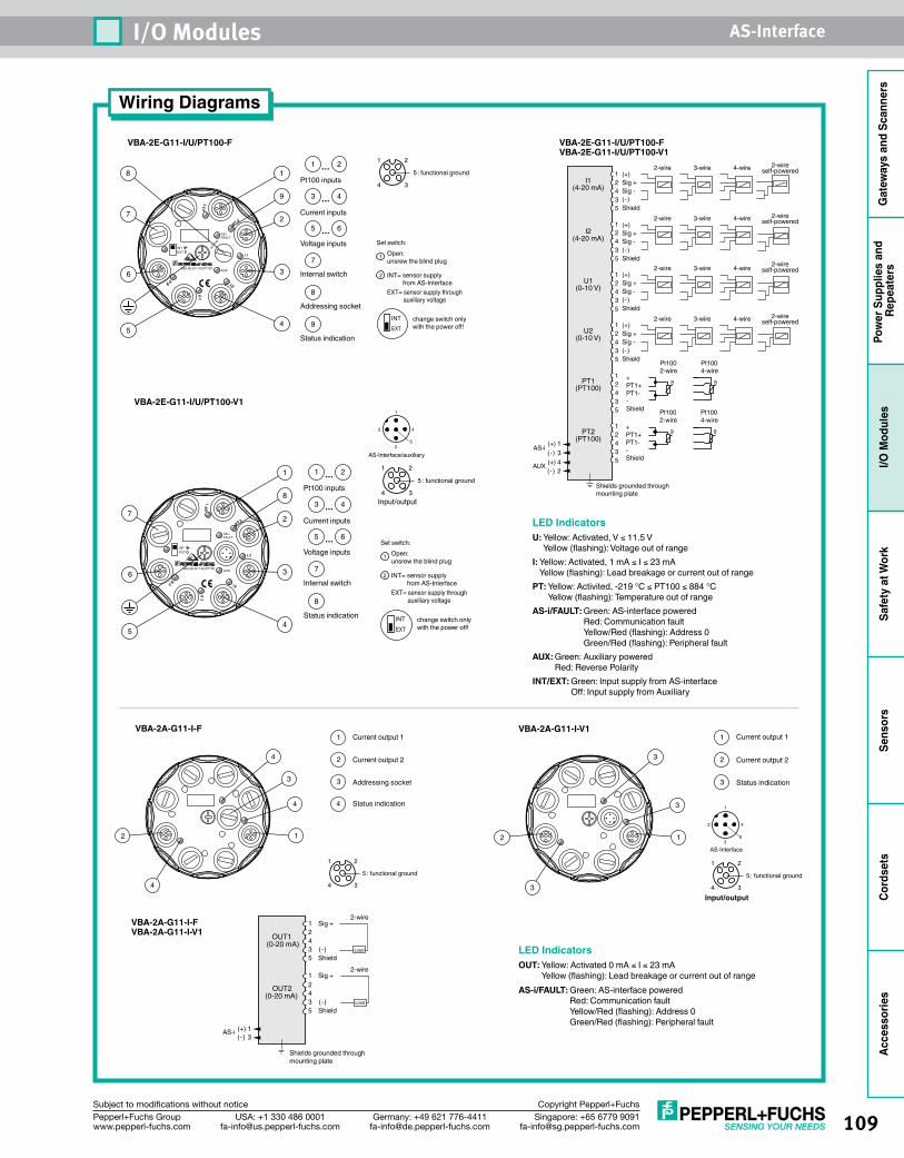
109Singapore: +65 6779 [email protected]
USA: +1 330 486 [email protected]
Germany: +49 621 [email protected]
Pepperl+Fuchs Groupwww.pepperl-fuchs.com
Subject to modifications without notice Copyright Pepperl+Fuchs
I/O Modules AS-Interface
Gat
eway
s an
d Sc
anne
rsPo
wer
Sup
plie
s an
d Re
peat
ers
I/O M
odul
esSa
fety
at W
ork
Sens
ors
Cord
sets
Acce
ssor
ies
Wiring Diagrams
VBA-2A-G11-I-F VBA-2A-G11-I-V1
VBA-2E-G11-I/U/PT100-FVBA-2E-G11-I/U/PT100-V1
LED IndicatorsOUT: Yellow: Activated 0 mA ≤ I ≤ 23 mA
Yellow (flashing): Lead breakage or current out of rangeAS-i/FAULT: Green: AS-interface powered
Red: Communication fault Yellow/Red (flashing): Address 0 Green/Red (flashing): Peripheral fault
1 2 4 3 5
1 2 4 3 5
1 2 4 3 5
1 2 4 3 5
I1(4-20 mA)
I2(4-20 mA)
U1(0-10 V)
U2(0-10 V)
PT1(PT100)
PT2(PT100)
12 4 3 5
1 2 4 3 5 (+) 4
(-) 2AUX
(+) 1(-) 3
AS-i
(+)Sig +Sig -(-)Shield
4-wire2-wire 2-wireself-powered3-wire
(+)Sig +Sig -(-)Shield
4-wire2-wire 2-wireself-powered3-wire
(+)Sig +Sig -(-)Shield
4-wire2-wire 2-wireself-powered3-wire
(+)Sig +Sig -(-)Shield
4-wire2-wire 2-wireself-powered3-wire
Pt1002-wire
Pt1004-wire
ϑ ϑ+PT1+PT1--Shield Pt100
2-wirePt1004-wire
ϑ ϑ+PT1+PT1--Shield
Shields grounded through mounting plate
Pt100 inputs
Voltage inputs
Status indication
Internal switch
Current inputs
Addressing socket
unsrew the blind plug
INT= sensor supply from AS-InterfaceEXT= sensor supply through auxiliary voltage
Open:Set switch:
change switch only with the power off!
: functional ground
1
2
INT
EXT
2 TP
VBA-2E-G11-I/U/PT100 AUX
AS-iFAULT
RD
DA
1 TP
I 1
I 2
U 2
U 1
INTEXT
4 3
1 2
5
9
11 2...
3 4...
7
2
3
4
8
7
6
5 6...
8
95
LED IndicatorsU: Yellow: Activated, V ≤ 11.5 V
Yellow (flashing): Voltage out of rangeI: Yellow: Activated, 1 mA ≤ I ≤ 23 mA
Yellow (flashing): Lead breakage or current out of rangePT: Yellow: Activited, -219 °C ≤ PT100 ≤ 884 °C
Yellow (flashing): Temperature out of rangeAS-i/FAULT: Green: AS-interface powered
Red: Communication fault Yellow/Red (flashing): Address 0 Green/Red (flashing): Peripheral fault
AUX: Green: Auxiliary powered Red: Reverse Polarity
INT/EXT: Green: Input supply from AS-interface Off: Input supply from Auxiliary
VBA-2E-G11-I/U/PT100-F
Pt100 inputs
Voltage inputs
Status indication
Internal switch
Current inputs
unsrew the blind plug
INT= sensor supply from AS-InterfaceEXT= sensor supply through auxiliary voltage
Open:Set switch:
change switch only with the power off!
: functional ground
1
2
INT
EXT
2 TP
VBA-2E-G11-I/U/PT100 AUX
AS-iFAULT
1 TP
I 1
I 2
U 2
U 1
INTEXT
4 3
1 2
5
8
1 1 2...
3 4...
7
2
3
4
7
6
5 6...
8
5
VBA-2E-G11-I/U/PT100-V1
Current output 1
Current output 2
Status indication
: functional ground
4 3
1 2
5
3
1
12
3
3
2
3
1 Sig +2 4
5 Shield
1 Sig +
3 (-)
2 4 3 (-)5 Shield
OUT1(0-20 mA)
OUT2(0-20 mA)
2-wire
2-wire
(+) 1(-) 3
AS-i
Load
Load
Shields grounded through mounting plate
VBA-2A-G11-I-FVBA-2A-G11-I-V1
Current output 1
Current output 2
Status indication
Addressing socket
: functional ground
4 3
1 2
5
4
1
4
3
12
4
4
2
3
Input/output
1
2 4
35
AS-Interface
Input/output
1
2 4
35
AS-Interface/auxiliary
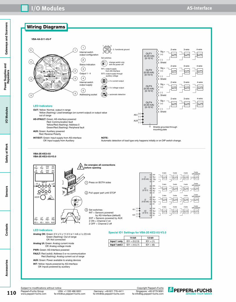
Gat
eway
s an
d Sc
anne
rsPo
wer
Sup
plie
s an
dRe
peat
ers
I/O M
odul
esSa
fety
at W
ork
Sens
ors
Cord
sets
Acce
ssor
ies
110 Singapore: +65 6779 [email protected]
USA: +1 330 486 [email protected]
Germany: +49 621 [email protected]
Pepperl+Fuchs Groupwww.pepperl-fuchs.com
Subject to modifications without notice Copyright Pepperl+Fuchs
I/O Modules AS-Interface
Wiring Diagrams
VBA-2E-KE2-I/UVBA-2E-KE2-I/U-V3.0
Press on BOTH sides1
2 Pull upper part until STOP
3 Set switches:INT = Sensors powered by AS-Interface (default)EXT = Sensors powered by AUX2 ON = Channel 2 on2 OFF = Channel 2 off
I1Sig+
I1Sig-
24Vext.
0Vext.
I2Sig+
I2Sig-
24Vext.
0Vext.
U1Sig+
U1Sig- Sig+ Sig-
U2 U2
AS-i+ AS-i- AUX+ AUX-
1 2 1 2
FAULT INT
PWR AUX
ADDR
UIOK
INPUT
INT
EXT
De-energize all connectionsbefore opening
OFFON2
24VSig +1Sig -
24V
0V
Sig +Sig -0V
I1(4-20 mA)
U1(0-10 V)
(+)(-)
AUX
4-wire2-wire 2-wireself-powered3-wire
4-wire2-wire 2-wireself-powered3-wire
24VSig +1Sig -
24V
0V
Sig +Sig -0V
I2(4-20 mA)
U2(0-10 V)
4-wire2-wire 2-wireself-powered3-wire
4-wire2-wire 2-wireself-powered3-wire
(+)(-)
AS-i
LED IndicatorsAnalog OK: Green: 0 V ≤ V ≤ 11.5 V or 1 mA ≤ I ≤ 23 mA
Green (flashing): Out of range Off: Not connected
Analog UI: Green: Analog current mode Off: Analog voltage mode
PWR: Green: AS-Interface poweredFAULT: Red (solid): Address 0 or no communication
Red (flashing): Analog current out of rangeAUX: Green: Power available to analog devicesINT: Yellow: Inputs powered by AS-Interface
Off: Inputs powered by auxiliary
Special ID1 Settings for VBA-2E-KE2-I/U-V3.0
14-bit 12-bitInput 1 only ID1 = (0,2,3) ID1 = (1)Input 1 and 2 ID1 = (4,5,7) ID1 = (6)
VBA-4A-G11-I/U-F
Internal switchoutput configuration
Output 1 - 4
Internal switchoutput supply
Status indication
Addressing socket
INT= output supply from AS-InterfaceEXT= output supply through auxiliary voltage
Set switches:
change switch only with the power off!
: functional ground
= 4 x current output
= 4 x voltage output
= automatic detection
INT
EXT
12
12
12
4 3
1 2
5
2
11
2
43
3
5
4
3
3
5
3
Part No. 237500VBA-4A-G11-I/U-F AUX
AS-iFAULT
DD
A
OUT1
OUT2
OUT4
OU
T3
40000000000000
INTEXT
IND.CONT.EQ.57M3AS-i: 26.5-31.6VDC, 200mAAUX: 20-30VDC, 700mA“Type1”
4U
4I
AUTO
LED IndicatorsOUT: Yellow: Normal, output in range
Yellow (flashing): Lead breakage (on current output) or output value out of range
AS-I/FAULT: Green: AS-interface powered Red: Communication fault Yellow/Red (flashing): Address 0 Green/Red (flashing): Peripheral fault
AUX: Green: Auxiliary powered Red: Reverse Polarity
INT/EXT: Green: Input supply from AS-interface Off: Input supply from Auxiliary
1 2 4 3 5
1 2 4 3 5
1 2 4 3 5
1 2 4 3 5
OUT1 (0-20 mA)
(0-10 V)
OUT2(0-20 mA)(0-10 V)
OUT3(0-20 mA)(0-10 V)
OUT4(0-20 mA)(0-10 V)
(+)(-)
AUX
(+)(-)
AS-i
Sig +(+) (-)Shield
2-wire 3-wire
Sig +(+) (-)Shield
4-wire2-wire 3-wire
Sig +(+) (-)Shield
2-wire 3-wire
Sig +(+) (-)Shield
2-wire 3-wire
Shields grounded through mounting plate
4-wire
4-wire
4-wire
NOTE: Automatic detection of load type only happens initially or on DIP switch change.
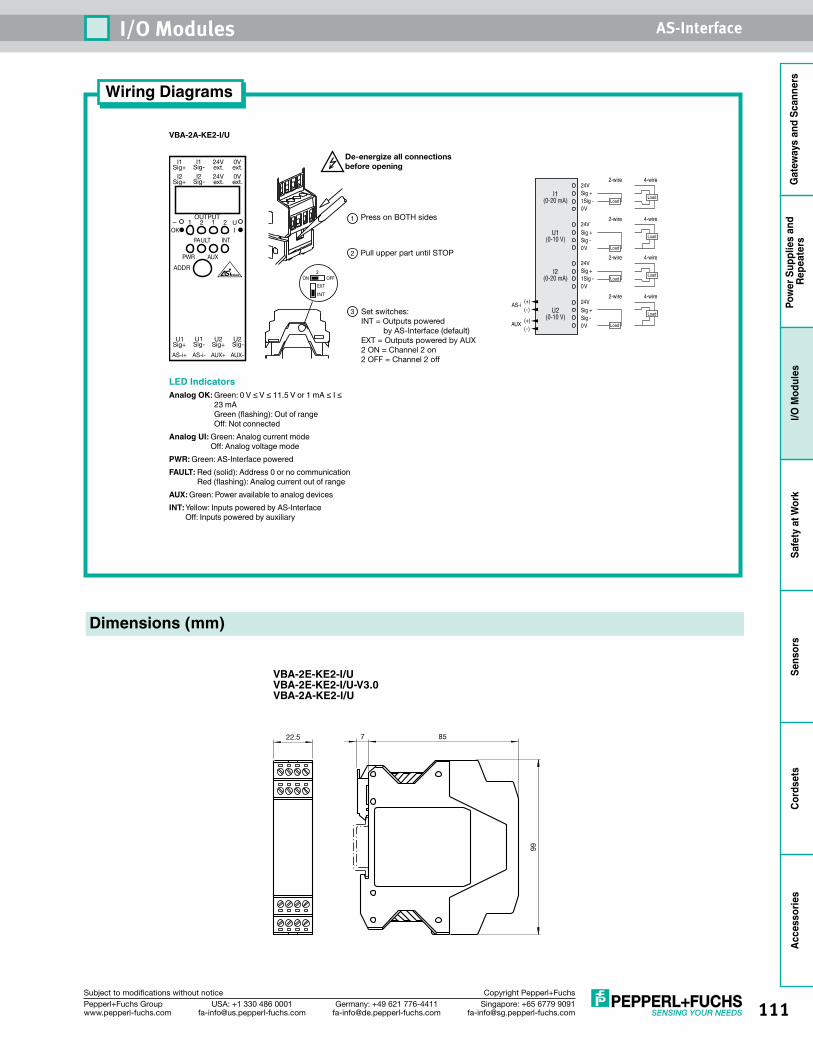
111Singapore: +65 6779 [email protected]
USA: +1 330 486 [email protected]
Germany: +49 621 [email protected]
Pepperl+Fuchs Groupwww.pepperl-fuchs.com
Subject to modifications without notice Copyright Pepperl+Fuchs
I/O Modules AS-Interface
Gat
eway
s an
d Sc
anne
rsPo
wer
Sup
plie
s an
d Re
peat
ers
I/O M
odul
esSa
fety
at W
ork
Sens
ors
Cord
sets
Acce
ssor
ies
VBA-2A-KE2-I/U
Press on BOTH sides1
2 Pull upper part until STOP
3 Set switches:INT = Outputs powered by AS-Interface (default)EXT = Outputs powered by AUX2 ON = Channel 2 on2 OFF = Channel 2 off
I1Sig+
I1Sig-
24Vext.
0Vext.
I2Sig+
I2Sig-
24Vext.
0Vext.
U1Sig+
U1Sig- Sig+ Sig-
U2 U2
AS-i+ AS-i- AUX+ AUX-
1 2 1 2
FAULT INT
PWR AUX
ADDR
UIOK
OUTPUT
INT
EXT
De-energize all connectionsbefore opening
OFFON2
LED IndicatorsAnalog OK: Green: 0 V ≤ V ≤ 11.5 V or 1 mA ≤ I ≤
23 mA Green (flashing): Out of range Off: Not connected
Analog UI: Green: Analog current mode Off: Analog voltage mode
PWR: Green: AS-Interface poweredFAULT: Red (solid): Address 0 or no communication
Red (flashing): Analog current out of rangeAUX: Green: Power available to analog devicesINT: Yellow: Inputs powered by AS-Interface
Off: Inputs powered by auxiliary
24VSig +1Sig -
24V
0V
Sig +Sig -0V
I1(0-20 mA)
U1(0-10 V)
(+)(-)
AUX
24VSig +1Sig -
24V
0V
Sig +Sig -0V
I2(0-20 mA)
U2(0-10 V)
(+)(-)
AS-i
4-wire2-wire
4-wire2-wire
LoadLoad
LoadLoad
4-wire2-wire
4-wire2-wire
Load
Load
Load
Load
Dimensions (mm)
Wiring Diagrams
22.5 857
99
VBA-2E-KE2-I/UVBA-2E-KE2-I/U-V3.0VBA-2A-KE2-I/U
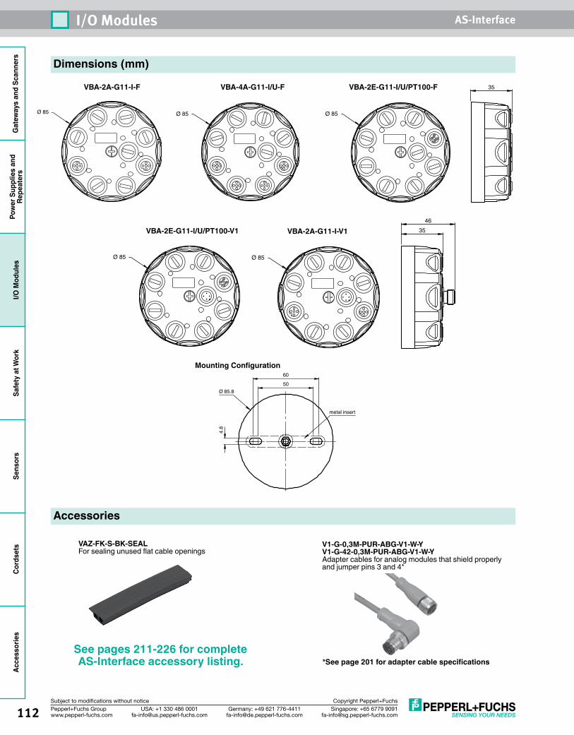
Gat
eway
s an
d Sc
anne
rsPo
wer
Sup
plie
s an
dRe
peat
ers
I/O M
odul
esSa
fety
at W
ork
Sens
ors
Cord
sets
Acce
ssor
ies
112 Singapore: +65 6779 [email protected]
USA: +1 330 486 [email protected]
Germany: +49 621 [email protected]
Pepperl+Fuchs Groupwww.pepperl-fuchs.com
Subject to modifications without notice Copyright Pepperl+Fuchs
I/O Modules AS-Interface
Dimensions (mm)
VBA-2A-G11-I-F
Accessories
See pages 211-226 for complete AS-Interface accessory listing.
3546
Ø 85
VBA-2A-G11-I-V14.
8
50
60
Ø 85.8
metal insert
Mounting Configuration
VAZ-FK-S-BK-SEALFor sealing unused flat cable openings
35
Ø 85
VBA-2E-G11-I/U/PT100-F
Ø 85Ø 85
VBA-4A-G11-I/U-F
VBA-2E-G11-I/U/PT100-V1
Ø 85
V1-G-0,3M-PUR-ABG-V1-W-YV1-G-42-0,3M-PUR-ABG-V1-W-YAdapter cables for analog modules that shield properly and jumper pins 3 and 4*
*See page 201 for adapter cable specifications
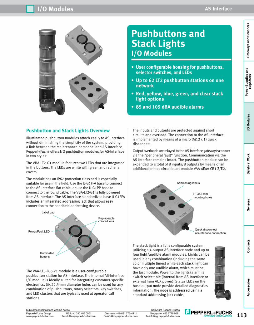
113Singapore: +65 6779 [email protected]
USA: +1 330 486 [email protected]
Germany: +49 621 [email protected]
Pepperl+Fuchs Groupwww.pepperl-fuchs.com
Subject to modifications without notice Copyright Pepperl+Fuchs
I/O Modules AS-Interface
Gat
eway
s an
d Sc
anne
rsPo
wer
Sup
plie
s an
d Re
peat
ers
I/O M
odul
esSa
fety
at W
ork
Sens
ors
Cord
sets
Acce
ssor
ies
Pushbuttons and Stack LightsI/O Modules• User configurable housing for pushbuttons,
selector switches, and LEDs• Up to 62 LT2 pushbutton stations on one
network• Red, yellow, blue, green, and clear stack
light options• 85 and 105 dBA audible alarms
Pushbutton and Stack Lights OverviewIlluminated pushbutton modules attach easily to AS-Interface without diminishing the simplicity of the system, providing a link between the maintenance personnel and AS-Interface. Pepperl+Fuchs offers I/O pushbutton modules for AS-Interface in two styles:
The VBA-LT2-G1 module features two LEDs that are integrated in the buttons. The LEDs are white with green and red lens covers.
The module has an IP67 protection class and is especially suitable for use in the field. Use the U-G1FFA base to connect to the AS-Interface flat cable, or use the U-G1PP base to connect to the round cable. The VBA-LT2-G1 is fully powered from AS-Interface. The AS-Interface standardized base U-G1FFA includes an integrated addressing jack that allows easy connection to the handheld addressing device.
The VAA-LT3-F86-V1 module is a user-configurable pushbutton station for AS-Interface. The internal AS-Interface I/O module is ideally suited for integrating customer-specific electronics. Six 22.5 mm diameter holes can be used for any combination of pushbuttons, rotary selectors, key switches, and LED clusters that are typically used at operator call stations.
The inputs and outputs are protected against short circuits and overload. The connection to the AS-Interface is implemented by means of a micro (M12 x 1) quick disconnect.
Output overloads are relayed to the AS-Interface gateway/scanner via the “peripheral fault” function. Communication via the AS-Interface remains intact. The pushbutton module can be expanded to a total of 8 inputs/8 outputs by means of an additional printed circuit board module VAA-4E4A-CB1-Z/E2.
The stack light is a fully configurable system utilizing a 4-output AS-Interface node and up to four light/audible alarm modules. Lights can be used in any combination (including the same color multiple times) while each stack light can have only one audible alarm, which must be the last module. Power to the lights/alarm is switch selectable (internal from AS-Interface or external from AUX power). Status LEDs on the base output node provide detailed diagnostics information. The node is addressed using a standard addressing jack cable.
Quick disconnectAS-Interface connection
Addressing labels
6 - 22.5 mmmounting holes
Illuminatedbuttons
Label pad
Replaceablecolored lens
Power/Fault LED
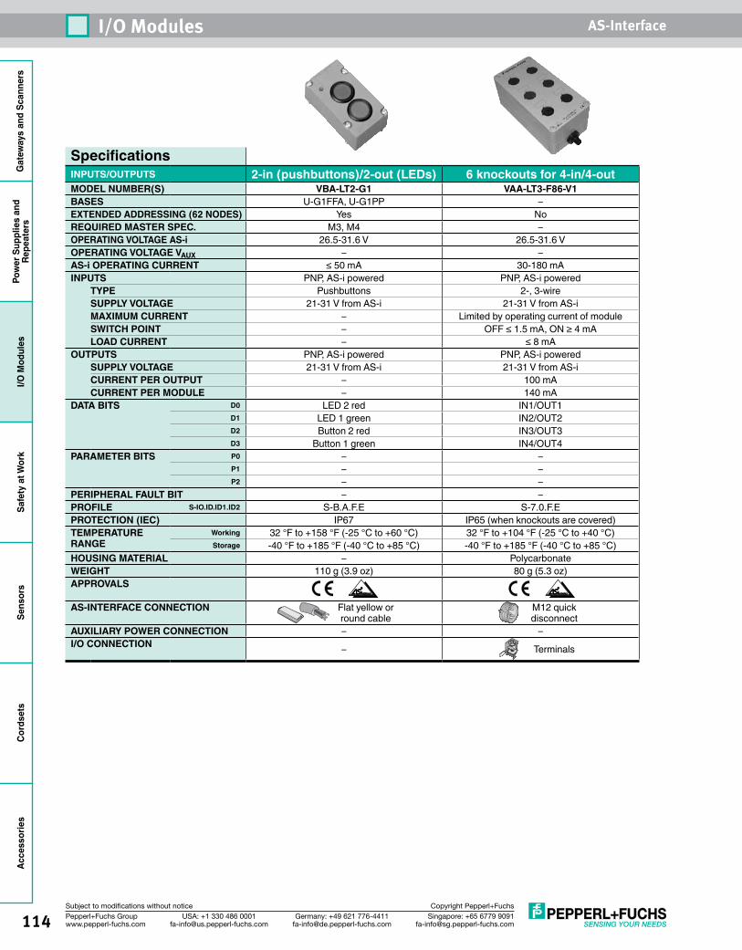
Gat
eway
s an
d Sc
anne
rsPo
wer
Sup
plie
s an
dRe
peat
ers
I/O M
odul
esSa
fety
at W
ork
Sens
ors
Cord
sets
Acce
ssor
ies
114 Singapore: +65 6779 [email protected]
USA: +1 330 486 [email protected]
Germany: +49 621 [email protected]
Pepperl+Fuchs Groupwww.pepperl-fuchs.com
Subject to modifications without notice Copyright Pepperl+Fuchs
I/O Modules AS-Interface
SpecificationsINPUTS/OUTPUTS 2-in (pushbuttons)/2-out (LEDs) 6 knockouts for 4-in/4-outMODEL NUMBER(S) VBA-LT2-G1 VAA-LT3-F86-V1BASES U-G1FFA, U-G1PP –EXTENDED ADDRESSING (62 NODES) Yes NoREQUIRED MASTER SPEC. M3, M4 –OPERATING VOLTAGE AS-i 26.5-31.6 V 26.5-31.6 VOPERATING VOLTAGE VAUX – –AS-i OPERATING CURRENT ≤ 50 mA 30-180 mAINPUTS PNP, AS-i powered PNP, AS-i powered
TYPE Pushbuttons 2-, 3-wireSUPPLY VOLTAGE 21-31 V from AS-i 21-31 V from AS-iMAXIMUM CURRENT – Limited by operating current of moduleSWITCH POINT – OFF ≤ 1.5 mA, ON ≥ 4 mALOAD CURRENT – ≤ 8 mA
OUTPUTS PNP, AS-i powered PNP, AS-i poweredSUPPLY VOLTAGE 21-31 V from AS-i 21-31 V from AS-iCURRENT PER OUTPUT – 100 mACURRENT PER MODULE – 140 mA
DATA BITS D0 LED 2 red IN1/OUT1D1 LED 1 green IN2/OUT2D2 Button 2 red IN3/OUT3D3 Button 1 green IN4/OUT4
PARAMETER BITS P0 – –P1 – –P2 – –
PERIPHERAL FAULT BIT – –PROFILE S-IO.ID.ID1.ID2 S-B.A.F.E S-7.0.F.EPROTECTION (IEC) IP67 IP65 (when knockouts are covered)TEMPERATURE RANGE
Working 32 °F to +158 °F (-25 °C to +60 °C) 32 °F to +104 °F (-25 °C to +40 °C)Storage -40 °F to +185 °F (-40 °C to +85 °C) -40 °F to +185 °F (-40 °C to +85 °C)
HOUSING MATERIAL – PolycarbonateWEIGHT 110 g (3.9 oz) 80 g (5.3 oz)APPROVALS
AS-INTERFACE CONNECTION Flat yellow or round cable
M12 quick disconnect
AUXILIARY POWER CONNECTION – –I/O CONNECTION – Terminals
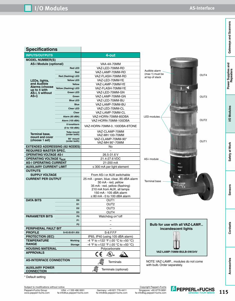
115Singapore: +65 6779 [email protected]
USA: +1 330 486 [email protected]
Germany: +49 621 [email protected]
Pepperl+Fuchs Groupwww.pepperl-fuchs.com
Subject to modifications without notice Copyright Pepperl+Fuchs
I/O Modules AS-Interface
Gat
eway
s an
d Sc
anne
rsPo
wer
Sup
plie
s an
d Re
peat
ers
I/O M
odul
esSa
fety
at W
ork
Sens
ors
Cord
sets
Acce
ssor
ies
SpecificationsINPUTS/OUTPUTS 4-outMODEL NUMBER(S)
AS-i Module (optional) VAA-4A-70MM
LEDs, lights, and Audible Alarms (choose up to 4 with AS-i, 5 without AS-i)
Red LED VAZ-LED-70MM-RDRed VAZ-LAMP-70MM-RD
Red (flashing) LED VAZ-FLASH-70MM-RDYellow LED VAZ-LED-70MM-YE
Yellow VAZ-LAMP-70MM-YEYellow (flashing) LED VAZ-FLASH-70MM-YE
Green LED VAZ-LED-70MM-GNGreen VAZ-LAMP-70MM-GN
Blue LED VAZ-LED-70MM-BUBlue VAZ-LAMP-70MM-BU
Clear LED VAZ-LED-70MM-CLClear VAZ-LAMP-70MM-CL
Alarm (85 dBA) VAZ-HORN-70MM-85DBAAlarm (105 dBA) VAZ-HORN-70MM-105DBA
8 toneAlarm (0 to 100 dBA) VAZ-HORN-70MM-0..100DBA-8TONE
Terminal base, mount and cover (choose 1 set)
Tube mount (order both)
VAZ-CLAMP-70MM VAZ-MH 100-70MM
90° mount (order both)
VAZ-CLAMP-70MM-90° VAZ-MH 90°-70MM
EXTENDED ADDRESSING (62 NODES) NoREQUIRED MASTER SPEC. –OPERATING VOLTAGE AS-i 26.5-31.6 VOPERATING VOLTAGE VAUX 21.4-27.6 VDCAS-i OPERATING CURRENT 21-200 mAAUXILIARY CURRENT LIMIT ≤ 300 mA per light elementOUTPUTS
SUPPLY VOLTAGE From AS-i or AUX switchableCURRENT PER OUTPUT 25 mA - green, blue, clear, 85 dBA alarm
30 mA - red, yellow 35 mA - red, yellow (flashing) 210 mA from AUX, all lamps
150 mA - 105 dBA alarm ≤ 80 mA - 0 to 100 dBA alarm
DATA BITS D0 OUT1D1 OUT2D2 OUT3D3 OUT4
PARAMETER BITS P0 Watchdog on*/offP1 –P2 –
PERIPHERAL FAULT BIT –PROFILE S-IO.ID.ID1.ID2 S-8.F.F.FPROTECTION (IEC) IP65, IP40 (using 105 dBA alarm)TEMPERATURE RANGE
Working -4 °F to +122 °F (-20 °C to +50 °C)Storage -4 °F to +122 °F (-20 °C to +50 °C)
HOUSING MATERIAL PolycarbonateAPPROVALS
AS-INTERFACE CONNECTION Terminals
AUXILIARY POWER CONNECTION Terminals (optional)
* Default setting
Audible alarm(max 1) must be at top of stack
LED modules
AS-i module
Terminal base
OUT1
OUT2
OUT3
OUT4
Bulb for use with all VAZ-LAMP...incandescent lights
NOTE: VAZ-LAMP... modules do not come with bulb. Order separately.
VAZ-LAMP-70MM-BULB-5W/24V
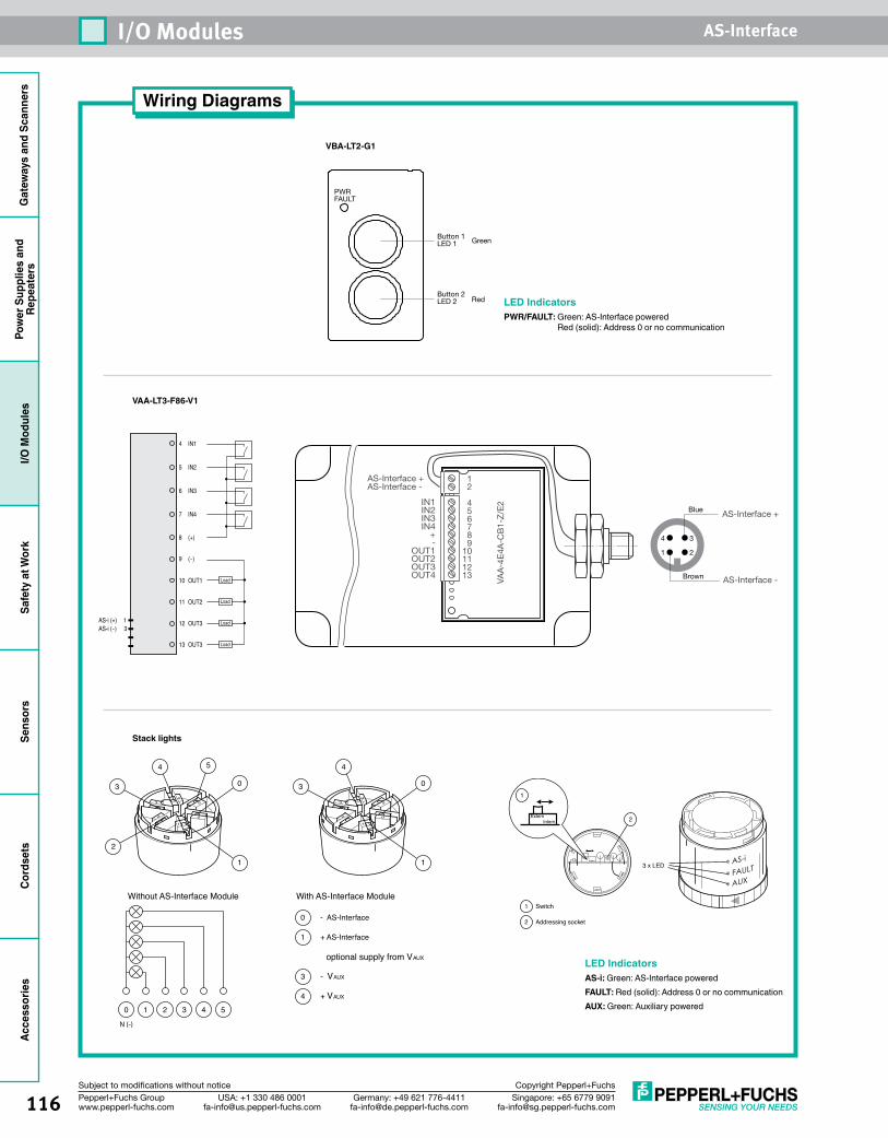
Gat
eway
s an
d Sc
anne
rsPo
wer
Sup
plie
s an
dRe
peat
ers
I/O M
odul
esSa
fety
at W
ork
Sens
ors
Cord
sets
Acce
ssor
ies
116 Singapore: +65 6779 [email protected]
USA: +1 330 486 [email protected]
Germany: +49 621 [email protected]
Pepperl+Fuchs Groupwww.pepperl-fuchs.com
Subject to modifications without notice Copyright Pepperl+Fuchs
I/O Modules AS-Interface
Wiring Diagrams
Button 1LED 1
PWRFAULT
Green
RedButton 2LED 2
AS-Interface +
VAA
-4E
4A-C
B1-
Z/E
2
AS-Interface -
AS-Interface +
AS-Interface -
IN1IN2IN3IN4
+-
OUT1OUT2OUT3OUT4
12
456789
10111213
1 2
4 3
Brown
Blue
4 IN1
5 IN2
6 IN3
7 IN4
9 (-)
10 OUT1
11 OUT2
12 OUT3
13 OUT3
8 (+)
Load
Load
Load
LoadAS-i (+) 1AS-i (-) 3
VAA-LT3-F86-V1
VBA-LT2-G1
LED IndicatorsPWR/FAULT: Green: AS-Interface powered
Red (solid): Address 0 or no communication
Stack lights
Switch
Addressing socket
1
2
ExternIntern AS-i
FAULT
AUX
3 x LED
2ExternIntern
1
LED IndicatorsAS-i: Green: AS-Interface poweredFAULT: Red (solid): Address 0 or no communicationAUX: Green: Auxiliary powered
optional supply from VAUX
With AS-Interface Module Without AS-Interface Module
1
0
1
03
4
0
1
- AS-Interface
+ AS-Interface
3
4
- VAUX
+ VAUX
3
4 5
2
0 1 2 3 4
N (-)
5
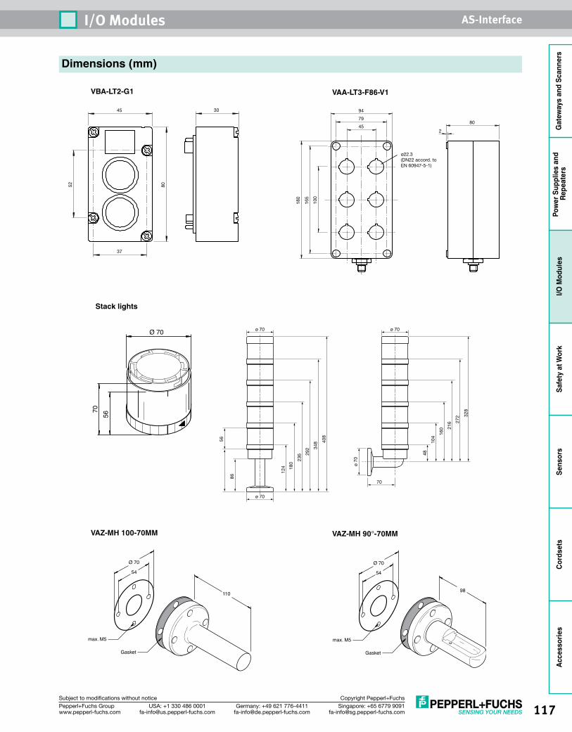
117Singapore: +65 6779 [email protected]
USA: +1 330 486 [email protected]
Germany: +49 621 [email protected]
Pepperl+Fuchs Groupwww.pepperl-fuchs.com
Subject to modifications without notice Copyright Pepperl+Fuchs
I/O Modules AS-Interface
Gat
eway
s an
d Sc
anne
rsPo
wer
Sup
plie
s an
d Re
peat
ers
I/O M
odul
esSa
fety
at W
ork
Sens
ors
Cord
sets
Acce
ssor
ies
Dimensions (mm)
VBA-LT2-G1
VAZ-MH 100-70MM
Stack lights
52
37
3045
80
Ø 70
5670
VAA-LT3-F86-V1
VAZ-MH 90°-70MM
ø22.3(DN22 accord. toEN 60947-5-1)
165
180
100
94
452
8079
ø 70
ø 70
180
124
236 29
2 348 40
8
56
86
70
ø 70
ø 70
104
48
160 21
6 272 32
8
Gasket
54
Ø 70
max. M5
110
Gasket
54
Ø 70
max. M5
98
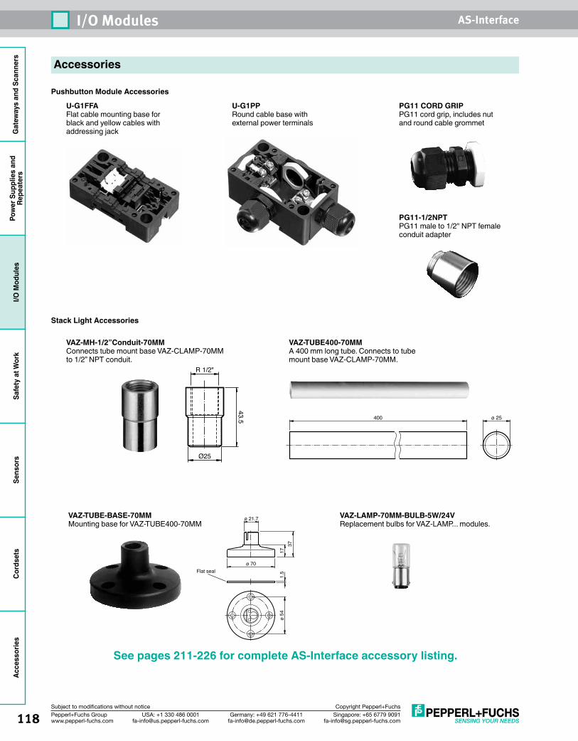
Gat
eway
s an
d Sc
anne
rsPo
wer
Sup
plie
s an
dRe
peat
ers
I/O M
odul
esSa
fety
at W
ork
Sens
ors
Cord
sets
Acce
ssor
ies
118 Singapore: +65 6779 [email protected]
USA: +1 330 486 [email protected]
Germany: +49 621 [email protected]
Pepperl+Fuchs Groupwww.pepperl-fuchs.com
Subject to modifications without notice Copyright Pepperl+Fuchs
I/O Modules AS-Interface
Accessories
Pushbutton Module Accessories
Stack Light Accessories
See pages 211-226 for complete AS-Interface accessory listing.
U-G1FFAFlat cable mounting base for black and yellow cables withaddressing jack
VAZ-MH-1/2”Conduit-70MMConnects tube mount base VAZ-CLAMP-70MM to 1/2” NPT conduit.
VAZ-TUBE400-70MMA 400 mm long tube. Connects to tube mount base VAZ-CLAMP-70MM.
U-G1PPRound cable base with external power terminals
PG11 CORD GRIPPG11 cord grip, includes nut and round cable grommet
PG11-1/2NPTPG11 male to 1/2" NPT female conduit adapter
VAZ-TUBE-BASE-70MMMounting base for VAZ-TUBE400-70MM
Flat seal
ø 21.7
1.5
1737
ø 70
ø 54
VAZ-LAMP-70MM-BULB-5W/24VReplacement bulbs for VAZ-LAMP... modules.
R 1/2"
Ø25
43.5 400 ø 25
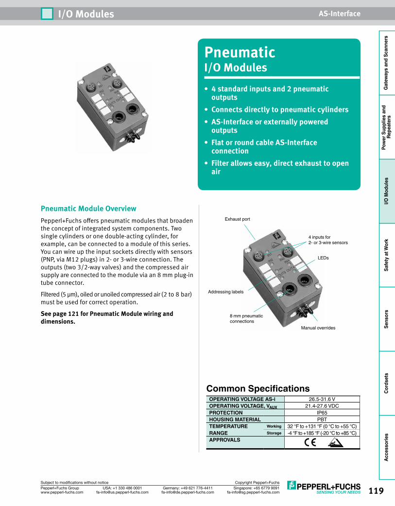
119Singapore: +65 6779 [email protected]
USA: +1 330 486 [email protected]
Germany: +49 621 [email protected]
Pepperl+Fuchs Groupwww.pepperl-fuchs.com
Subject to modifications without notice Copyright Pepperl+Fuchs
I/O Modules AS-Interface
Gat
eway
s an
d Sc
anne
rsPo
wer
Sup
plie
s an
d Re
peat
ers
I/O M
odul
esSa
fety
at W
ork
Sens
ors
Cord
sets
Acce
ssor
ies
PneumaticI/O Modules• 4 standard inputs and 2 pneumatic
outputs• Connects directly to pneumatic cylinders• AS-Interface or externally powered
outputs• Flat or round cable AS-Interface
connection• Filter allows easy, direct exhaust to open
air
Pneumatic Module OverviewPepperl+Fuchs offers pneumatic modules that broaden the concept of integrated system components. Two single cylinders or one double-acting cylinder, for example, can be connected to a module of this series. You can wire up the input sockets directly with sensors (PNP, via M12 plugs) in 2- or 3-wire connection. The outputs (two 3/2-way valves) and the compressed air supply are connected to the module via an 8 mm plug-in tube connector.
Filtered (5 µm), oiled or unoiled compressed air (2 to 8 bar) must be used for correct operation.
See page 121 for Pneumatic Module wiring and dimensions.
Addressing labels
Exhaust port
4 inputs for2- or 3-wire sensors
LEDs
8 mm pneumatic connections
Manual overrides
Common SpecificationsOPERATING VOLTAGE AS-i 26.5-31.6 VOPERATING VOLTAGE, VAUX 21.4-27.6 VDCPROTECTION IP65HOUSING MATERIAL PBTTEMPERATURE Working 32 °F to +131 °F (0 °C to +55 °C)RANGE Storage -4 °F to +185 °F (-20 °C to +85 °C)APPROVALS

Gat
eway
s an
d Sc
anne
rsPo
wer
Sup
plie
s an
dRe
peat
ers
I/O M
odul
esSa
fety
at W
ork
Sens
ors
Cord
sets
Acce
ssor
ies
120 Singapore: +65 6779 [email protected]
USA: +1 330 486 [email protected]
Germany: +49 621 [email protected]
Pepperl+Fuchs Groupwww.pepperl-fuchs.com
Subject to modifications without notice Copyright Pepperl+Fuchs
I/O Modules AS-Interface
SpecificationsINPUTS/OUTPUTS 4-in/ 2-out (pneumatic AS-i powered) 4-in/2-out (pneumatic AUX powered)MODEL NUMBER(S)* VBA-4E2A-G1-ZE/P-S VBA-4E2A-G1-ZE/PEXT-SBASES U-G1FFA, U-G1PPEXTENDED ADDRESSING (62 NODES) Yes
REQUIRED MASTER SPEC. M3, M4AS-i OPERATING CURRENT 45-195 mA 45-145 mAAUXILIARY CURRENT LIMIT – ≤ 50 mAINPUTS -ZE PNP, AS-i powered
–TYPE 2-, 3-, 4-wireSUPPLY VOLTAGE 21-31 V from AS-InterfaceMAXIMUM CURRENT 100 mASWITCH POINT OFF ≤ 1.5 mA, ON ≥ 5 mALOAD CURRENT ≤ 8 mA
OUTPUTS P-S, PEXT-S Pneumatic, AS-i powered Pneumatic, AUX poweredSUPPLY VOLTAGE From AS-Interface From auxiliaryAIR VENTING Sinter filterCOMPRESSED AIR 2-8 bar, filtered (5 µm), oiled or unoiledAIR THROUGHPUT 550 I/min at 6/0 bar, 350 I/min at 6/5 barCONNECTION 8 mm
DATA BITS D0 IN1/OUT1D1 IN2/OUT2D2 IN3D3 IN4
PARAMETER BITS
P0 –P1 –P2 –
PERIPHERAL FAULT BIT Input overloadPROFILE S-IO.ID.ID1.ID2 S-7.A.7.EWEIGHT 230 g (8 oz)AS-INTERFACE CONNECTION Flat yellow or
round cableAUXILIARY POWER CONNECTION – Flat black or
round cableI/O CONNECTION M12 quick disconnect
and 8 mm pneumatic
*Also AvailableINPUTS/OUTPUTS Model Number Base
Required Master Spec.
Profile S-IO.
ID.ID1.ID2
Extended Address-
ingSpecial Features
4-in/2-out VAA-4E2A-G1-ZE/P-S U-G1FFA, U-G1PP – S-7.F.F.F No4-in/2-out VAA-4E2A-G1-ZE/PEXT-S U-G1FFA, U-G1PP – S-7.F.F.F No Auxiliary-powered outputs 2-in/2-out VAA-2EA-G1-ZE/P-S U-G1FFA, U-G1PP – S-3.F.F.F No2-in/2-out VAA-2EA-G1-ZE/P-V2A U-G1FFA, U-G1PP – S-3.F.F.F No 8 mm exhaust port, stainless steel
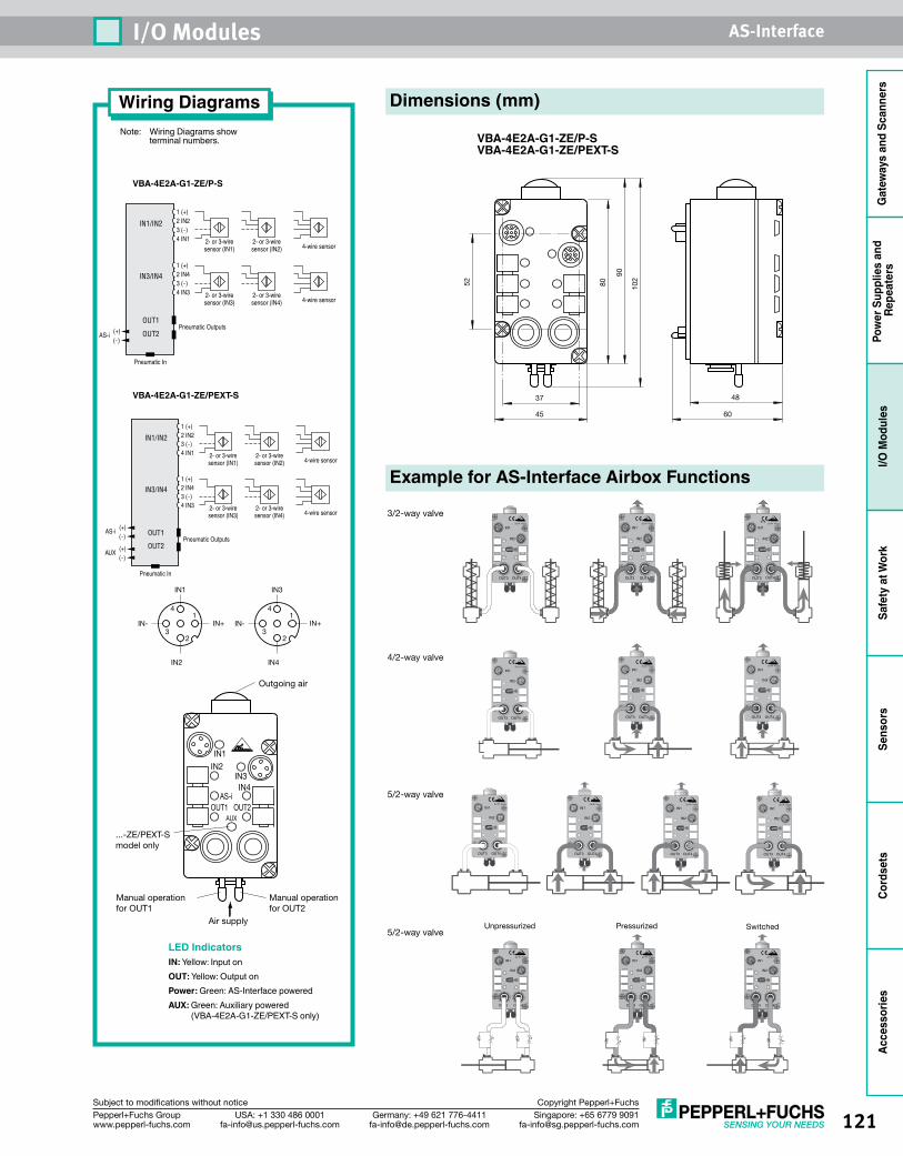
121Singapore: +65 6779 [email protected]
USA: +1 330 486 [email protected]
Germany: +49 621 [email protected]
Pepperl+Fuchs Groupwww.pepperl-fuchs.com
Subject to modifications without notice Copyright Pepperl+Fuchs
I/O Modules AS-Interface
Gat
eway
s an
d Sc
anne
rsPo
wer
Sup
plie
s an
d Re
peat
ers
I/O M
odul
esSa
fety
at W
ork
Sens
ors
Cord
sets
Acce
ssor
ies
1 (+)2 IN23 (-)4 IN1
1 (+)2 IN43 (-)4 IN3
Pneumatic Outputs
Pneumatic In
4-wire sensor2- or 3-wiresensor (IN1)
2- or 3-wiresensor (IN2)
4-wire sensor2- or 3-wiresensor (IN3)
2- or 3-wiresensor (IN4)
IN1/IN2
IN3/IN4
OUT1
OUT2(+)(-)
AS-i
1 (+)2 IN23 (-)4 IN1
1 (+)2 IN43 (-)4 IN3
Pneumatic Outputs
Pneumatic In
4-wire sensor2- or 3-wiresensor (IN1)
2- or 3-wiresensor (IN2)
4-wire sensor2- or 3-wiresensor (IN3)
2- or 3-wiresensor (IN4)
IN1/IN2
IN3/IN4
OUT1
OUT2(+)(-)
AUX
(+)(-)
AS-i
Outgoing air
Manual operationfor OUT2
Manual operationfor OUT1
...-ZE/PEXT-S model only
Air supply
OUT1 OUT2
IN1
AS-
AUX
i
IN2IN3IN4
IN1
IN- IN+
4
3
1
2
4
3
1
2
IN2
IN3
IN- IN+
IN4
Outgoing air
Manual operationfor OUT2
Manual operationfor OUT1
...-ZE/PEXT-S model only
Air supply
OUT1 OUT2
IN1
AS-
AUX
i
IN2IN3IN4
IN1
IN- IN+
4
3
1
2
4
3
1
2
IN2
IN3
IN- IN+
IN4
Wiring DiagramsNote: Wiring Diagrams show terminal numbers.
VBA-4E2A-G1-ZE/P-S
VBA-4E2A-G1-ZE/PEXT-S
LED IndicatorsIN: Yellow: Input onOUT: Yellow: Output onPower: Green: AS-Interface poweredAUX: Green: Auxiliary powered
(VBA-4E2A-G1-ZE/PEXT-S only)
Dimensions (mm)
VBA-4E2A-G1-ZE/P-SVBA-4E2A-G1-ZE/PEXT-S
80
90
10252
37 48
6045
Example for AS-Interface Airbox Functions
Unpressurized Pressurized Switched
OUT3 OUT4
IN1
IN2
Power
ZU-Nr. Xxxxx
OUT3 OUT4
IN1
IN2
Power
ZU-Nr. Xxxxx
OUT3 OUT4
IN1
IN2
Power
ZU-Nr. Xxxxx
OUT3 OUT4
IN1
IN2
Power
ZU-Nr. Xxxxx
OUT3 OUT4
IN1
IN2
Power
ZU-Nr. Xxxxx
OUT3 OUT4
IN1
IN2
Power
ZU-Nr. Xxxxx
OUT3 OUT4
IN1
IN2
Power
ZU-Nr. Xxxxx
OUT3 OUT4
IN1
IN2
Power
ZU-Nr. Xxxxx
OUT3 OUT4
IN1
IN2
Power
ZU-Nr. Xxxxx
OUT3 OUT4
IN1
IN2
Power
ZU-Nr. Xxxxx
OUT3 OUT4
IN1
IN2
Power
ZU-Nr. Xxxxx
OUT3 OUT4
IN1
IN2
Power
ZU-Nr. Xxxxx
OUT3 OUT4
IN1
IN2
Power
ZU-Nr. Xxxxx
3/2-way valve
4/2-way valve
5/2-way valve
5/2-way valve
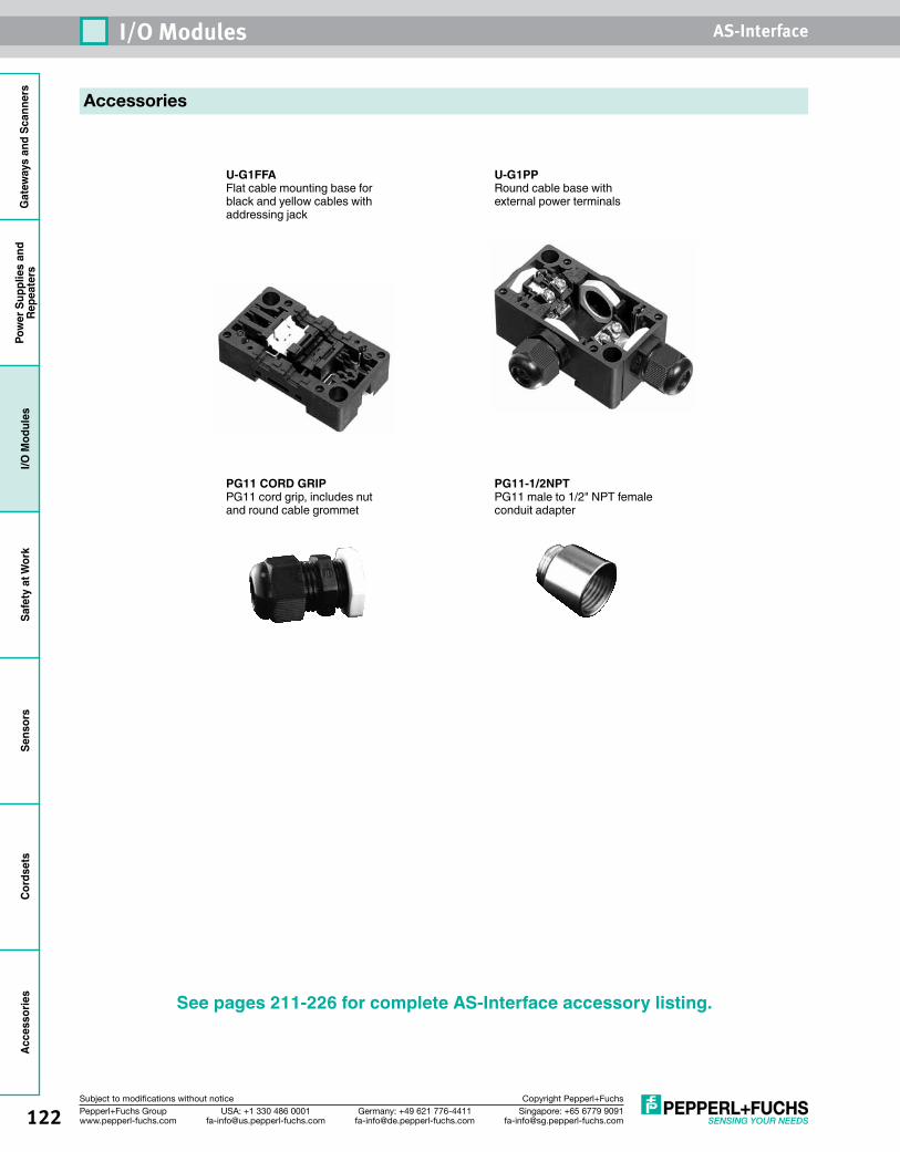
Gat
eway
s an
d Sc
anne
rsPo
wer
Sup
plie
s an
dRe
peat
ers
I/O M
odul
esSa
fety
at W
ork
Sens
ors
Cord
sets
Acce
ssor
ies
122 Singapore: +65 6779 [email protected]
USA: +1 330 486 [email protected]
Germany: +49 621 [email protected]
Pepperl+Fuchs Groupwww.pepperl-fuchs.com
Subject to modifications without notice Copyright Pepperl+Fuchs
I/O Modules AS-Interface
Accessories
See pages 211-226 for complete AS-Interface accessory listing.
U-G1FFAFlat cable mounting base for black and yellow cables withaddressing jack
U-G1PPRound cable base with external power terminals
PG11 CORD GRIPPG11 cord grip, includes nut and round cable grommet
PG11-1/2NPTPG11 male to 1/2" NPT female conduit adapter
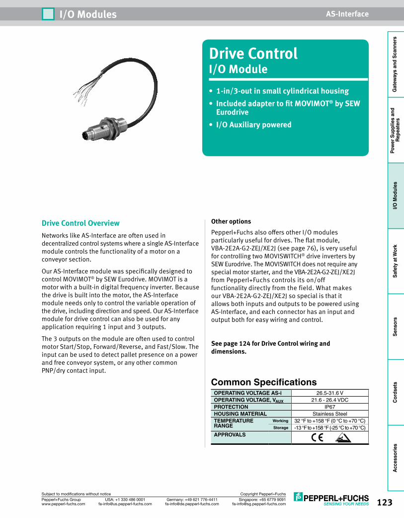
123Singapore: +65 6779 [email protected]
USA: +1 330 486 [email protected]
Germany: +49 621 [email protected]
Pepperl+Fuchs Groupwww.pepperl-fuchs.com
Subject to modifications without notice Copyright Pepperl+Fuchs
I/O Modules AS-Interface
Gat
eway
s an
d Sc
anne
rsPo
wer
Sup
plie
s an
d Re
peat
ers
I/O M
odul
esSa
fety
at W
ork
Sens
ors
Cord
sets
Acce
ssor
ies
Drive ControlI/O Module• 1-in/3-out in small cylindrical housing• Included adapter to fit MOVIMOT® by SEW
Eurodrive• I/O Auxiliary powered
Drive Control OverviewNetworks like AS-Interface are often used in decentralized control systems where a single AS-Interface module controls the functionality of a motor on a conveyor section.
Our AS-Interface module was specifically designed to control MOVIMOT® by SEW Eurodrive. MOVIMOT is a motor with a built-in digital frequency inverter. Because the drive is built into the motor, the AS-Interface module needs only to control the variable operation of the drive, including direction and speed. Our AS-Interface module for drive control can also be used for any application requiring 1 input and 3 outputs.
The 3 outputs on the module are often used to control motor Start/Stop, Forward/Reverse, and Fast/Slow. The input can be used to detect pallet presence on a power and free conveyor system, or any other common PNP/dry contact input.
Other optionsPepperl+Fuchs also offers other I/O modules particularly useful for drives. The flat module, VBA-2E2A-G2-ZEJ/XE2J (see page 76), is very useful for controlling two MOVISWITCH® drive inverters by SEW Eurodrive. The MOVISWITCH does not require any special motor starter, and the VBA-2E2A-G2-ZEJ/XE2J from Pepperl+Fuchs controls its on/off functionality directly from the field. What makes our VBA-2E2A-G2-ZEJ/XE2J so special is that it allows both inputs and outputs to be powered using AS-Interface, and each connector has an input and output both for easy wiring and control.
See page 124 for Drive Control wiring and dimensions.
Common SpecificationsOPERATING VOLTAGE AS-i 26.5-31.6 VOPERATING VOLTAGE, VAUX 21.6 - 26.4 VDCPROTECTION IP67HOUSING MATERIAL Stainless SteelTEMPERATURE Working 32 °F to +158 °F (0 °C to +70 °C)RANGE Storage -13 °F to +158 °F (-25 °C to +70 °C)APPROVALS
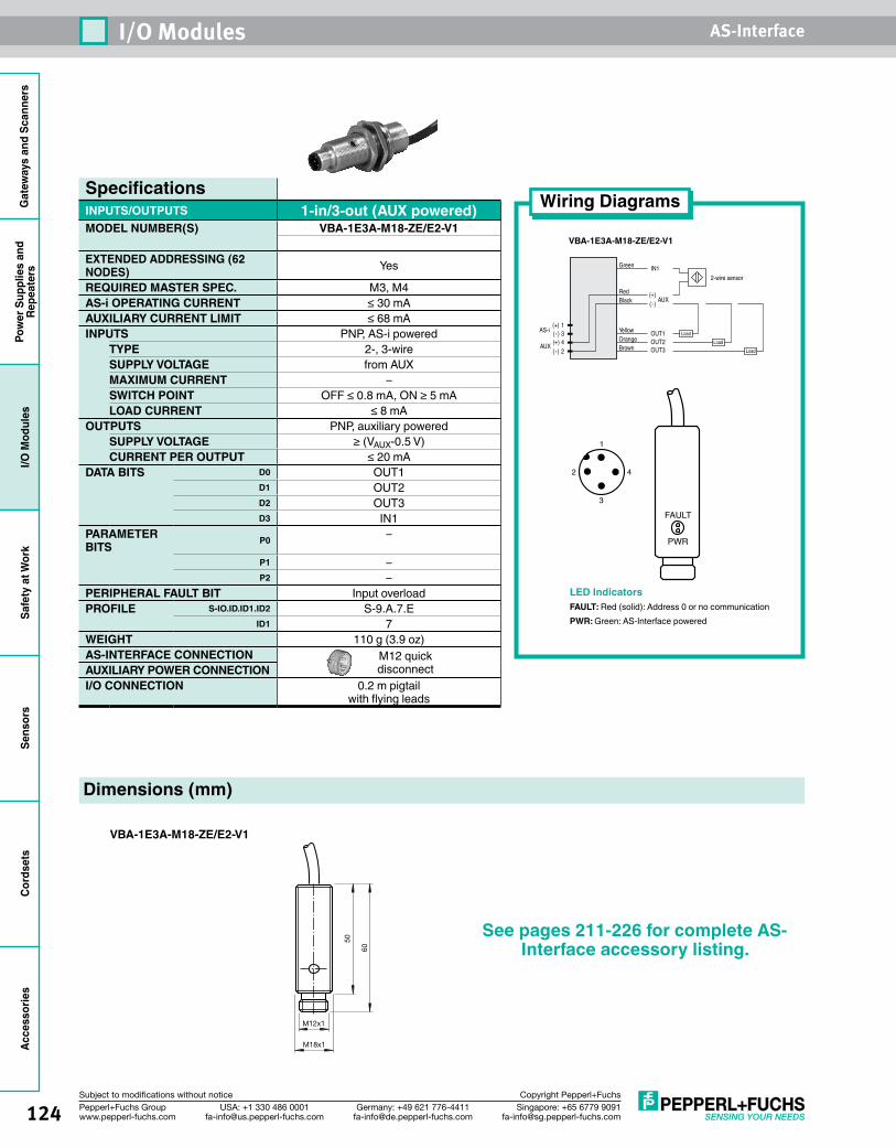
Gat
eway
s an
d Sc
anne
rsPo
wer
Sup
plie
s an
dRe
peat
ers
I/O M
odul
esSa
fety
at W
ork
Sens
ors
Cord
sets
Acce
ssor
ies
124 Singapore: +65 6779 [email protected]
USA: +1 330 486 [email protected]
Germany: +49 621 [email protected]
Pepperl+Fuchs Groupwww.pepperl-fuchs.com
Subject to modifications without notice Copyright Pepperl+Fuchs
I/O Modules AS-Interface
Wiring Diagrams
VBA-1E3A-M18-ZE/E2-V1
Dimensions (mm)
VBA-1E3A-M18-ZE/E2-V1
(+) 1(-) 3(+) 4(-) 2
AUX
AS-i
2-wire sensor
Green IN1
OUT1OUT2OUT3
YellowOrangeBrown
RedBlack
Load
Load
Load
(+)(-)
AUX
SpecificationsINPUTS/OUTPUTS 1-in/3-out (AUX powered)MODEL NUMBER(S) VBA-1E3A-M18-ZE/E2-V1
EXTENDED ADDRESSING (62 NODES) Yes
REQUIRED MASTER SPEC. M3, M4AS-i OPERATING CURRENT ≤ 30 mAAUXILIARY CURRENT LIMIT ≤ 68 mAINPUTS PNP, AS-i powered
TYPE 2-, 3-wireSUPPLY VOLTAGE from AUXMAXIMUM CURRENT –SWITCH POINT OFF ≤ 0.8 mA, ON ≥ 5 mALOAD CURRENT ≤ 8 mA
OUTPUTS PNP, auxiliary poweredSUPPLY VOLTAGE ≥ (VAUX-0.5 V)CURRENT PER OUTPUT ≤ 20 mA
DATA BITS D0 OUT1D1 OUT2D2 OUT3D3 IN1
PARAMETER BITS P0 –
P1 –P2 –
PERIPHERAL FAULT BIT Input overloadPROFILE S-IO.ID.ID1.ID2 S-9.A.7.E
ID1 7WEIGHT 110 g (3.9 oz)AS-INTERFACE CONNECTION M12 quick
disconnectAUXILIARY POWER CONNECTIONI/O CONNECTION 0.2 m pigtail
with flying leads
LED IndicatorsFAULT: Red (solid): Address 0 or no communicationPWR: Green: AS-Interface powered
50
60
M12x1
M18x1
See pages 211-226 for complete AS-Interface accessory listing.

125Singapore: +65 6779 [email protected]
USA: +1 330 486 [email protected]
Germany: +49 621 [email protected]
Pepperl+Fuchs Groupwww.pepperl-fuchs.com
Subject to modifications without notice Copyright Pepperl+Fuchs
AS-Interface
Gat
eway
s an
d Sc
anne
rsPo
wer
Sup
plie
s an
d Re
peat
ers
I/O M
odul
esSa
fety
at W
ork
Sens
ors
Cord
sets
Acce
ssor
ies
Singapore: +65 6779 [email protected]
USA: +1 330 486 [email protected]
Germany: +49 621 [email protected]
Pepperl+Fuchs Groupwww.pepperl-fuchs.com
Subject to modifications without notice Copyright Pepperl+Fuchs
Safety at Work
OverviewAS-Interface Safety at Work (SaW) is a system that enables networking of safety devices (safety door switches, emergency stop pushbuttons, safety light arrays, etc.) using standard AS-Interface networks. With SaW, users can quickly implement a safety system that satisfies the rules and regulations needed for Category 4/SIL 3, PLe Safety. The simplicity of AS-Interface is retained and is a major reason for users to implement SaW systems.
The following features make SaW unique and powerful:
• Control I/O and safety information on the same network
• Usable up to Safety Category 4, SIL 3, PLe
• Does not require a Safety PLC
• Automatic single SafetyNode replacement is supported
• SafetyMonitor allows implementation of powerful safety procedures
• Safe inputs and outputs both supported
• Scan one or two networks simultaneously
• Up to 16 safe, independent output/coupling channels on a single network
• Adding safety devices is fast and easy
What is needed?SaW utilizes AS-Interface's proven wiring design to transmit safety information (position of an e-stop, state of a blade switch, position of a key switch, etc.)from a SafetyNode to a SafetyMonitor. SafetyNode and SafetyMonitor are the only new hardware items needed to implement SaW. The AS-Interface gateway/ scanner and the AS-Interface power supply remain the same. The power supply and gateway/scanner chosen enable communication over the network and reflect the parameters of the job (e.g, the upper-level network used, speed of application, etc.), but do not affect the safety level.
Safe input modulesSafetyNodes are I/O modules that have been designed and constructed to satisfy the rules and regulations necessary to obtain desired safety ratings. This construction includes redundancy at the inputs and internal components. A SafetyNode transmits 4 bits of data like any other I/O module, but with the SafetyNode, the 4 bits transmitted from the module to the AS-Interface gateway/scanner follow special rules that allow the SafetyMonitor to determine whether an e-stop has been activated. The gateway/scanner evaluates this data in the same manner as the data from a "nonsafe" I/O module. The SafetyMonitor takes the place of a safety relay in conventional hardwire systems.
Safe output modulesSafety output modules work opposite to the way that safe input modules do. The SafetyMonitor generates an address called the safe output channel. This safe output channel and a standard A/B address are programmed into the safety output module. The safety sequence is transmitted over the safe output channel only when the SafetyMonitor determines that its configuration is safe. This information from the SafetyMonitor is then evaluated by the safe output module and the safe contacts are closed. If the SafetyMonitor determines that the machine must stop, all data bits transmitted via the safe output channel are set to 0. Diagnostics and
Safety Monitors .......................................... 129Safe Input/Output Modules ......................... 134Emergency Stops ........................................ 143Mechanical Safety Interlock Switches .......... 146Coded Magnetic Safety Interlock Switches ............................ 152RFID Safety Interlock Switches .................... 155Enabling Switch .......................................... 159
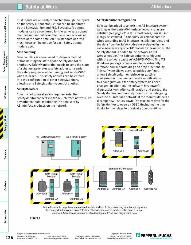
126 Singapore: +65 6779 [email protected]
USA: +1 330 486 [email protected]
Germany: +49 621 [email protected]
Pepperl+Fuchs Groupwww.pepperl-fuchs.com
Subject to modifications without notice Copyright Pepperl+Fuchs
Safety at Work AS-InterfaceG
atew
ays
and
Scan
ners
Pow
er S
uppl
ies
and
Repe
ater
sI/O
Mod
ules
Safe
ty a
t Wor
kSe
nsor
sCo
rdse
tsAc
cess
orie
s
EDM inputs are all sent/connected through the inputs on the safety output module that can be monitored by the SafetyMonitor and PLC. Several safe output modules can be configured for the same safe output channel and, in that case, their safe contacts will all switch at the same time. An A/B standard address must, however, be unique for each safety output module used.
Safe couplingSafe coupling is a term used to define a method of transmitting the state of one SafetyMonitor to another. A SafetyMonitor that needs to send the state of a channel generates a safety address. It sends the safety sequence while running and sends 0000 when released. This safety address can be entered into the configuration of other SafetyMonitors, allowing one SafetyMonitor to control another.
SafetyMonitorsConstructed to meet safety requirements, the SafetyMonitor connects to the AS-Interface network like any other module, monitoring the data sent by AS-Interface modules on the network.
SafetyMonitor configuration
SaW can be added to an existing AS-Interface system as long as the basic AS-Interface network rules are satisfied (see pages 21-25). In most cases, SaW is used alongside standard I/O modules. All components are wired according to AS-Interface installation rules, and the data from the SafetyNodes are evaluated in the same manner as any other I/O module on the network. The SafetyMonitor is added to the network as if it were a module. The SafetyMonitor is configured with the software package VAZ-SW-SIMON+. This MS Windows package offers a simple, user-friendly interface and supports drag and drop functionality. This software allows users to quickly configure a new SafetyMonitor, or retrieve an existing configuration from one, and make modifications to a configuration if the safety system has been changed. In addition, the software has powerful diagnostics tool. After configuration and startup, the SafetyMonitor continuously monitors the data going over the AS-Interface network. If the monitor detects a discrepancy, it shuts down. The maximum time for the SafetyMonitor to open an OSSD (including the time it take for the relays to physically open) is 40 ms.
AS-i Power SupplyAS-i Gateway/Scanner
SafetyNode
Address 1
Address 3
Address 8
Address 7BAddress 7A
Address 8
Address 3A Address 4 Address 4A
Address 2
SafetyMonitor
Safe Ouput Module
Safe Ouput Module
Standard I/O Modules
Two safe, remote output modules share the safe address 8, thus switching simultaneously when the SafetyMonitor signals an on/off state. The two safe output modules also have a unique,
standard A/B address to transmit standard inputs, EDM, and diagnostics data.
Figure 1
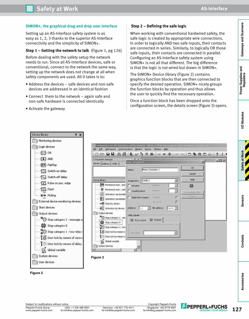
127Singapore: +65 6779 [email protected]
USA: +1 330 486 [email protected]
Germany: +49 621 [email protected]
Pepperl+Fuchs Groupwww.pepperl-fuchs.com
Subject to modifications without notice Copyright Pepperl+Fuchs
Safety at Work AS-Interface
Gat
eway
s an
d Sc
anne
rsPo
wer
Sup
plie
s an
d Re
peat
ers
I/O M
odul
esSa
fety
at W
ork
Sens
ors
Cord
sets
Acce
ssor
ies
SIMON+, the graphical drag and drop user interface
Setting up an AS-Interface safety system is as easy as 1, 2, 3 thanks to the superior AS-Interface connectivity and the simplicity of SIMON+.
Step 1 – Getting the network to talk (Figure 1, pg 126)Before dealing with the safety setup the network needs to run. Since all AS-Interface devices, safe or conventional, connect to the network the same way, setting up the network does not change at all when safety components are used. All it takes is to:
• Address the devices – safe devices and non-safe devices are addressed in an identical fashion
• Connect them to the network – again safe and non-safe hardware is connected identically
• Activate the gateway
Step 2 – Defining the safe logic
When working with conventional hardwired safety, the safe logic is created by appropriate wire connections. In order to logically AND two safe inputs, their contacts are connected in series. Similarly, to logically OR those safe inputs, their contacts are connected in parallel. Configuring an AS-Interface safety system using SIMON+ is not all that different. The big difference is that the logic is not wired but drawn in SIMON+.The SIMON+ Device library (Figure 2) contains graphics function blocks that are then connected to specify the desired operation. SIMON+ nicely groups the function blocks by operation and thus allows the user to quickly find the necessary operation.Once a function block has been dropped onto the configuration screen, the details screen (Figure 3) opens.
Figure 2
Figure 3
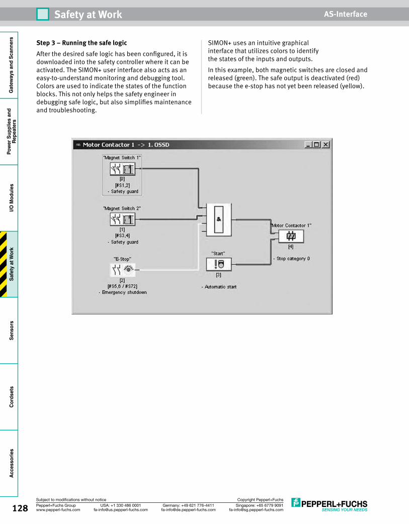
128 Singapore: +65 6779 [email protected]
USA: +1 330 486 [email protected]
Germany: +49 621 [email protected]
Pepperl+Fuchs Groupwww.pepperl-fuchs.com
Subject to modifications without notice Copyright Pepperl+Fuchs
Safety at Work AS-InterfaceG
atew
ays
and
Scan
ners
Pow
er S
uppl
ies
and
Repe
ater
sI/O
Mod
ules
Safe
ty a
t Wor
kSe
nsor
sCo
rdse
tsAc
cess
orie
s
Step 3 – Running the safe logicAfter the desired safe logic has been configured, it is downloaded into the safety controller where it can be activated. The SIMON+ user interface also acts as an easy-to-understand monitoring and debugging tool. Colors are used to indicate the states of the function blocks. This not only helps the safety engineer in debugging safe logic, but also simplifies maintenance and troubleshooting.
SIMON+ uses an intuitive graphical interface that utilizes colors to identify the states of the inputs and outputs.In this example, both magnetic switches are closed and released (green). The safe output is deactivated (red) because the e-stop has not yet been released (yellow).

129Singapore: +65 6779 [email protected]
USA: +1 330 486 [email protected]
Germany: +49 621 [email protected]
Pepperl+Fuchs Groupwww.pepperl-fuchs.com
Subject to modifications without notice Copyright Pepperl+Fuchs
Safety at Work AS-Interface
Gat
eway
s an
d Sc
anne
rsPo
wer
Sup
plie
s an
d Re
peat
ers
I/O M
odul
esSa
fety
at W
ork
Sens
ors
Cord
sets
Acce
ssor
ies
Safety MonitorsSafety Solutions• Connects to standard AS-Interface
network• Monitors status of safety inputs and sets
safe outputs• Safety requirements in accordance with
category 4 to EN 954-1• Comes with one or two redundant relay
outputs, electronic outputs, and up to 16 safe output channels
• Safe coupling allows communication between safety monitors
Monitors OverviewThe safety monitor is an integral part of an AS-Interface Safety at Work system. A safety monitor can be a stand-alone device, as seen in this section, or can be combined in a safety monitor/gateway combination. This combination has the advantage of being less expensive for a two-network system and has very fast diagnostics. See pages 41 and 48 if this is the best option for your application. Stand-alone safety monitors are a great way to achieve a low-cost, safe output on AS-Interface, because AS-Interface safety can be added to any network regardless of age or master type.Common safety monitor terms include:Safe outputs These are the onboard OSSDs (Output Signal Switching Devices) on the safety monitor and can be electronic or relay. These outputs are always redundant and used to switch a contactor, safe relay, or cut auxiliary power.Safe output channels A safety monitor has safe outputs; some can be on board and others can be remotely activated. This unique combination of both onboard and remote outputs provides the total number of available safe output channels. Remote safe outputs require the use of a safe output module as well.Safe coupling channels If multiple safety monitors are on one network, safety data can be exchanged between each monitor using the safe coupling channel. A safe coupling channel is simply a safety slave set up by one safety monitor and
received by another. Some of the safety monitors have multiple AS-Interface connections, allowing them to couple from one network to another.
Monitor Options16-channel safety monitorThis is the most powerful safety monitor. It offers connectivity to two AS-Interface networks with up to 31 safety modules on each network. Up to 16 safety output channels are available with two safe electronic and two safe relay channels on board. Extra diagnostics are also available, including ground fault detection and duplicate address detection.8-channel safety monitorThe 8-channel is a lower cost, yet full-featured safety monitor.It can scan safety devices on only one network, but has two safe electronic OSSDs on board and up to six unique remote safe output channels. Eight inputs are available and can be configured for connection of standard inputs, safe dry contact inputs, or safe electronic inputs.2-channel safety monitorThis is one of the original safety monitors. It has one AS-Interface connection for safe inputs and one for the safe output or coupling channel. This allows complete flexibility to use one network only or couple to a second network. The safe relays are available to switch 120 VAC if required.
See pages 131-132 for SafetyMonitor wiring and dimensions.
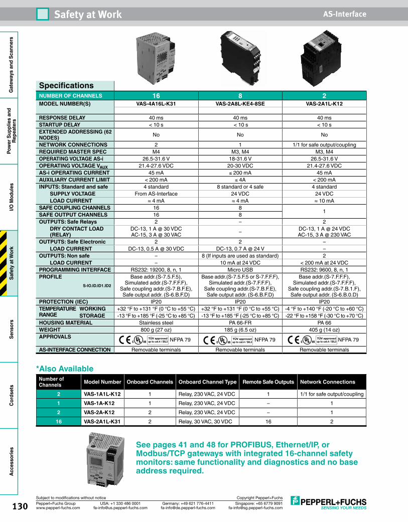
130 Singapore: +65 6779 [email protected]
USA: +1 330 486 [email protected]
Germany: +49 621 [email protected]
Pepperl+Fuchs Groupwww.pepperl-fuchs.com
Subject to modifications without notice Copyright Pepperl+Fuchs
Safety at Work AS-InterfaceG
atew
ays
and
Scan
ners
Pow
er S
uppl
ies
and
Repe
ater
sI/O
Mod
ules
Safe
ty a
t Wor
kSe
nsor
sCo
rdse
tsAc
cess
orie
s
SpecificationsNUMBER OF CHANNELS 16 8 2MODEL NUMBER(S) VAS-4A16L-K31 VAS-2A8L-KE4-8SE VAS-2A1L-K12
RESPONSE DELAY 40 ms 40 ms 40 msSTARTUP DELAY < 10 s < 10 s < 10 sEXTENDED ADDRESSING (62 NODES) No No No
NETWORK CONNECTIONS 2 1 1/1 for safe output/couplingREQUIRED MASTER SPEC M4 M3, M4 M3, M4OPERATING VOLTAGE AS-i 26.5-31.6 V 18-31.6 V 26.5-31.6 VOPERATING VOLTAGE VAUX 21.4-27.6 VDC 20-30 VDC 21.4-27.6 VDCAS-i OPERATING CURRENT 45 mA ≤ 200 mA 45 mAAUXILIARY CURRENT LIMIT < 200 mA ≤ 4A < 200 mAINPUTS: Standard and safe 4 standard 8 standard or 4 safe 4 standard
SUPPLY VOLTAGE From AS-Interface 24 VDC 24 VDCLOAD CURRENT ≈ 4 mA ≈ 4 mA ≈ 10 mA
SAFE COUPLING CHANNELS 16 8 1SAFE OUTPUT CHANNELS 16 8OUTPUTS: Safe Relays 2 – 2
DRY CONTACT LOAD (RELAY)
DC-13, 1 A @ 30 VDC AC-15, 3 A @ 30 VAC – DC-13, 1 A @ 24 VDC
AC-15, 3 A @ 230 VACOUTPUTS: Safe Electronic 2 2 –
LOAD CURRENT DC-13, 0.5 A @ 30 VDC DC-13, 0.7 A @ 24 V –OUTPUTS: Non safe – 8 (If inputs are used as standard) 2
LOAD CURRENT – 10 mA at 24 VDC < 200 mA at 24 VDCPROGRAMMING INTERFACE RS232: 19200, 8, n, 1 Micro USB RS232: 9600, 8, n, 1PROFILE
S-IO.ID.ID1.ID2
Base addr.(S-7.5.F.5), Simulated addr.(S-7.F.F.F),
Safe coupling addr.(S-7.B.F.E), Safe output addr. (S-6.B.F.D)
Base addr.(S-7.5.F.5 or S-7.F.F.F), Simulated addr.(S-7.F.F.F),
Safe coupling addr.(S-7.B.F.E), Safe output addr. (S-6.B.F.D)
Base addr.(S-7.F.F.F), Simulated addr.(S-7.F.F.F),
Safe coupling addr.(S-7.B.1.F), Safe output addr. (S-6.B.0.D)
PROTECTION (IEC) IP20 IP20 IP20TEMPERATURE RANGE
WORKING +32 °F to +131 °F (0 °C to +55 °C) +32 °F to +131 °F (0 °C to +55 °C) -4 °F to +140 °F (-20 °C to +60 °C)STORAGE -13 °F to +185 °F (-25 °C to +85 °C) -13 °F to +185 °F (-25 °C to +85 °C) -22 °F to +158 °F (-30 °C to +70 °C)
HOUSING MATERIAL Stainless steel PA 66-FR PA 66WEIGHT 800 g (27 oz) 185 g (6.5 oz) 405 g (14 oz)APPROVALS NFPA 79 NFPA 79 NFPA 79
AS-INTERFACE CONNECTION Removable terminals Removable terminals Removable terminals
TÜV approvedup to cat.4 / SIL3
TÜV approvedup to cat.4 / SIL3
See pages 41 and 48 for PROFIBUS, Ethernet/IP, or Modbus/TCP gateways with integrated 16-channel safety monitors: same functionality and diagnostics and no base address required.
*Also AvailableNumber of Channels Model Number Onboard Channels Onboard Channel Type Remote Safe Outputs Network Connections
2 VAS-1A1L-K12 1 Relay, 230 VAC, 24 VDC 1 1/1 for safe output/coupling1 VAS-1A-K12 1 Relay, 230 VAC, 24 VDC – 12 VAS-2A-K12 2 Relay, 230 VAC, 24 VDC – 1
16 VAS-2A1L-K31 2 Relay, 30 VAC, 30 VDC 16 2
TÜV approvedup to cat.4 / SIL3
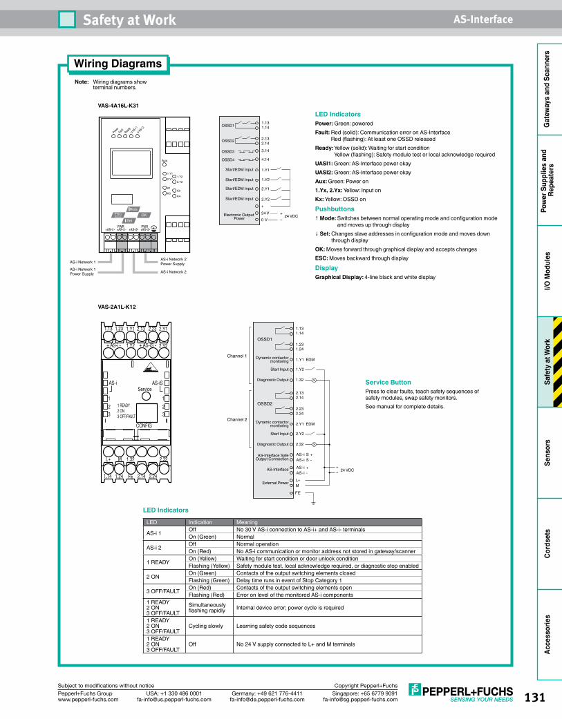
131Singapore: +65 6779 [email protected]
USA: +1 330 486 [email protected]
Germany: +49 621 [email protected]
Pepperl+Fuchs Groupwww.pepperl-fuchs.com
Subject to modifications without notice Copyright Pepperl+Fuchs
Safety at Work AS-Interface
Gat
eway
s an
d Sc
anne
rsPo
wer
Sup
plie
s an
d Re
peat
ers
I/O M
odul
esSa
fety
at W
ork
Sens
ors
Cord
sets
Acce
ssor
ies
Wiring DiagramsNote: Wiring diagrams show terminal numbers.
VAS-4A16L-K31
VAS-2A1L-K12
AS-iService
1
2
1
23 3
CONFIG
1 READY2 ON3 OFF/FAULT
1.13 1.23 1.Y1
1.Y2
2.13 2.23 2.Y1
2.Y2
L+ M 1.32 2.32
1.14 1.24 FE 2.14 2.24
AS-iS
+ AS-iS -+ AS-i -
1.131.14
1.231.24
1.Y2Start Input
Dynamic contactormonitoring
Diagnostic Output
1.Y1 EDM
1.32
OSSD1
Channel 1
L+M
FE
AS-i +AS-i -
AS-i S +AS-i S -
2.132.14
2.232.24
2.Y2Start Input
Dynamic contactormonitoring
Diagnostic Output
2.Y1 EDM
2.32
OSSD2
Channel 2
24 VDC+–
External Power
AS-Interface
AS-Interface Safe Output Connection
Service ButtonPress to clear faults, teach safety sequences of safety modules, swap safety monitors.See manual for complete details.
OKESCMode
Set
PowerFau
ltRead
yU AS-i 1
Aux
1.Y1
2.Y11.Y2
2.Y2
K1
K4K3
K2
U AS-i 2
Service
AS-i Network 1
AS-i Network 1Power Supply
AS-i Network 2 Power Supply
AS-i Network 2
+AS-i1- +AS-i1-PWR
+AS-i2- +AS-i2-PWR
1.131.14
2.132.14
1.Y2
Start/EDM Input
Start/EDM Input
Start/EDM Input
Start/EDM Input
1.Y1
2.Y2
2.Y1
OSSD1
3.14
4.14
OSSD2
OSSD3
OSSD4
+
24 V0 V
24 VDC+–
Electronic Output Power
LED IndicatorsPower: Green: poweredFault: Red (solid): Communication error on AS-Interface
Red (flashing): At least one OSSD releasedReady: Yellow (solid): Waiting for start condition
Yellow (flashing): Safety module test or local acknowledge requiredUASI1: Green: AS-Interface power okayUASI2: Green: AS-Interface power okay Aux: Green: Power on1.Yx, 2.Yx: Yellow: Input onKx: Yellow: OSSD on
Pushbuttons↑ Mode: Switches between normal operating mode and configuration mode
and moves up through display↓ Set: Changes slave addresses in configuration mode and moves down
through displayOK: Moves forward through graphical display and accepts changesESC: Moves backward through display
DisplayGraphical Display: 4-line black and white display
LED Indicators
LED Indication Meaning
AS-i 1 Off No 30 V AS-i connection to AS-i+ and AS-i- terminalsOn (Green) Normal
AS-i 2 Off Normal operationOn (Red) No AS-i communication or monitor address not stored in gateway/scanner
1 READY On (Yellow) Waiting for start condition or door unlock conditionFlashing (Yellow) Safety module test, local acknowledge required, or diagnostic stop enabled
2 ON On (Green) Contacts of the output switching elements closedFlashing (Green) Delay time runs in event of Stop Category 1
3 OFF/FAULT On (Red) Contacts of the output switching elements openFlashing (Red) Error on level of the monitored AS-i components
1 READY2 ON3 OFF/FAULT
Simultaneously flashing rapidly Internal device error; power cycle is required
1 READY2 ON3 OFF/FAULT
Cycling slowly Learning safety code sequences
1 READY2 ON3 OFF/FAULT
Off No 24 V supply connected to L+ and M terminals
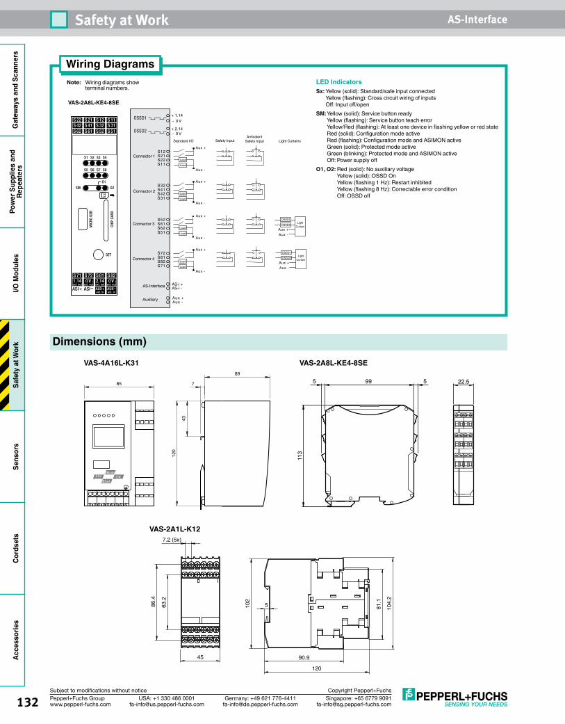
132 Singapore: +65 6779 [email protected]
USA: +1 330 486 [email protected]
Germany: +49 621 [email protected]
Pepperl+Fuchs Groupwww.pepperl-fuchs.com
Subject to modifications without notice Copyright Pepperl+Fuchs
Safety at Work AS-InterfaceG
atew
ays
and
Scan
ners
Pow
er S
uppl
ies
and
Repe
ater
sI/O
Mod
ules
Safe
ty a
t Wor
kSe
nsor
sCo
rdse
tsAc
cess
orie
s
Wiring DiagramsNote: Wiring diagrams show terminal numbers.
VAS-2A8L-KE4-8SE
+ 1.14- 0 V
+ 2.14- 0 V
Connector 1
Connector 2
OSSD1
S12
AS-i +
Aux +
OSSD2
S21S22S11
Connector 3
Connector 4
AS-Interface
Auxiliary
S32S41S42S31
S52S61S62S51
S72S81S82S71
Load
Load
Load
Load
Load
Load
Load
Load
Aux -
AS-i -
Standard I/O Safety Input
Aux -
Aux -
Aux -
Aux -
Aux +
Aux +
Aux +
Aux +
Antivalent Safety Input Light Curtains
LightCurtain
Aux +Aux -
OSSD1
OSSD2
LightCurtain
Aux +Aux -
OSSD1
OSSD2
LED IndicatorsSx: Yellow (solid): Standard/safe input connected
Yellow (flashing): Cross circuit wiring of inputs Off: Input off/open
SM: Yellow (solid): Service button ready Yellow (flashing): Service button teach error Yellow/Red (flashing): At least one device in flashing yellow or red state Red (solid): Configuration mode active Red (flashing): Configuration mode and ASIMON active Green (solid): Protected mode active Green (blinking): Protected mode and ASIMON active Off: Power supply off
O1, O2: Red (solid): No auxiliary voltage Yellow (solid): OSSD On Yellow (flashing 1 Hz): Restart inhibited Yellow (flashing 8 Hz): Correctable error condition Off: OSSD off
Dimensions (mm)
VAS-4A16L-K31
OKMode
SetESC
Service
89
7
43
120
85
VAS-2A8L-KE4-8SE
113
995 22.55
VAS-2A1L-K127.2 (5x)
86.4
63.2
45
104.
2
81.1
102
5
90.9
120

133Singapore: +65 6779 [email protected]
USA: +1 330 486 [email protected]
Germany: +49 621 [email protected]
Pepperl+Fuchs Groupwww.pepperl-fuchs.com
Subject to modifications without notice Copyright Pepperl+Fuchs
Safety at Work AS-Interface
Gat
eway
s an
d Sc
anne
rsPo
wer
Sup
plie
s an
d Re
peat
ers
I/O M
odul
esSa
fety
at W
ork
Sens
ors
Cord
sets
Acce
ssor
ies
Accessories
VAZ-SIMON-R2AS-Interface cable for programming (only used with VAS-2A1L-K12 models).
VAZ-SIMON-RJ45AS-Interface cable for downloading configuration from one monitor to another (only used with VAS-2A1L-K12 models).
See pages 211-226 for complete AS-Interface accessory listing.
VAZ-SW-SIMON+Configuration software for all SafetyMonitors. Cables not included.
VAZ-SIMON+-R2-1,8M-PS/2AS-Interface cable for programming (only used with VAS-4A16L-K31 models).
VAZ-SIMON-USBAS-Interface cable for programming (only used with VAS-2A8L-KE4-8SE models).

134 Singapore: +65 6779 [email protected]
USA: +1 330 486 [email protected]
Germany: +49 621 [email protected]
Pepperl+Fuchs Groupwww.pepperl-fuchs.com
Subject to modifications without notice Copyright Pepperl+Fuchs
Safety at Work AS-InterfaceG
atew
ays
and
Scan
ners
Pow
er S
uppl
ies
and
Repe
ater
sI/O
Mod
ules
Safe
ty a
t Wor
kSe
nsor
sCo
rdse
tsAc
cess
orie
s
Safe Input/Output ModulesSafety Solutions• Available in field and enclosure mount
versions• Easily connect existing safe components
to modules• Standard outputs can be controlled by
PLC or directly by module• Connect two safe inputs for Category 2
safety• Connect one safe input for Category 3/4
safety
Safe Input/Output Modules OverviewSafetyNodes are I/O modules that have been designed and constructed to satisfy the rules and regulations necessary to obtain desired safety ratings. This construction includes redundancy at the inputs and internal components.
Safe input modulesTypically, safe input modules are used to connect existing safety devices or muting sensors. Modules are available in a number of housing designs to accept dry contacts from an emergency stop or electronic outputs from a light curtain or muting sensor. Also safety input modules have the advantage of accepting two Category 2 inputs when a higher level of safety isn’t necessary. The advantage is that two Category 2 e-stops, for example, would take up one AS-Interface address where two integrated AS-Interface e-stops would require two addresses.
Safe output modulesThe safety output module has the same safety output rating as a SafetyMonitor, but without programming. All of the programming and logic still resides on the SafetyMonitor itself. The safe output module should be viewed as a remote set of safe contacts controlled
by the SafetyMonitor. These are often used to control motors locally and safely. Two addresses are programmed into the safety output module. The first is the safe data channel that controls the safe operation of the module, and the second is an A/B address that is used for EDM inputs and diagnostics. Multiple modules can have the same safe data channel if required.
Safe output nodes can also be configured so that their safe relay output is controlled by the PLC. If there is a problem, the SafetyMonitor will act as an override and release the relay.
See pages 139-140 for Safety Solutions Safe Input/Output Modules wiring and dimensions.
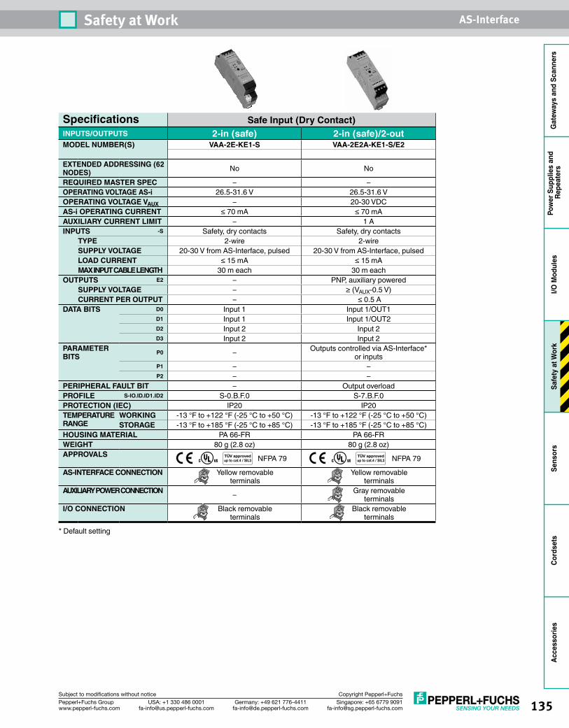
135Singapore: +65 6779 [email protected]
USA: +1 330 486 [email protected]
Germany: +49 621 [email protected]
Pepperl+Fuchs Groupwww.pepperl-fuchs.com
Subject to modifications without notice Copyright Pepperl+Fuchs
Safety at Work AS-Interface
Gat
eway
s an
d Sc
anne
rsPo
wer
Sup
plie
s an
d Re
peat
ers
I/O M
odul
esSa
fety
at W
ork
Sens
ors
Cord
sets
Acce
ssor
ies
Specifications Safe Input (Dry Contact)INPUTS/OUTPUTS 2-in (safe) 2-in (safe)/2-outMODEL NUMBER(S) VAA-2E-KE1-S VAA-2E2A-KE1-S/E2
EXTENDED ADDRESSING (62 NODES) No No
REQUIRED MASTER SPEC – –OPERATING VOLTAGE AS-i 26.5-31.6 V 26.5-31.6 VOPERATING VOLTAGE VAUX – 20-30 VDCAS-i OPERATING CURRENT ≤ 70 mA ≤ 70 mAAUXILIARY CURRENT LIMIT – 1 AINPUTS -S Safety, dry contacts Safety, dry contacts
TYPE 2-wire 2-wireSUPPLY VOLTAGE 20-30 V from AS-Interface, pulsed 20-30 V from AS-Interface, pulsedLOAD CURRENT ≤ 15 mA ≤ 15 mAMAX INPUT CABLE LENGTH 30 m each 30 m each
OUTPUTS E2 – PNP, auxiliary poweredSUPPLY VOLTAGE – ≥ (VAUX-0.5 V)CURRENT PER OUTPUT – ≤ 0.5 A
DATA BITS D0 Input 1 Input 1/OUT1D1 Input 1 Input 1/OUT2D2 Input 2 Input 2D3 Input 2 Input 2
PARAMETER BITS P0 – Outputs controlled via AS-Interface*
or inputsP1 – –P2 – –
PERIPHERAL FAULT BIT – Output overloadPROFILE S-IO.ID.ID1.ID2 S-0.B.F.0 S-7.B.F.0PROTECTION (IEC) IP20 IP20TEMPERATURE RANGE
WORKING -13 °F to +122 °F (-25 °C to +50 °C) -13 °F to +122 °F (-25 °C to +50 °C)STORAGE -13 °F to +185 °F (-25 °C to +85 °C) -13 °F to +185 °F (-25 °C to +85 °C)
HOUSING MATERIAL PA 66-FR PA 66-FRWEIGHT 80 g (2.8 oz) 80 g (2.8 oz)APPROVALS NFPA 79 NFPA 79
AS-INTERFACE CONNECTION Yellow removable terminals
Yellow removable terminals
AUXILIARY POWER CONNECTION – Gray removable terminals
I/O CONNECTION Black removable terminals
Black removable terminals
* Default setting
TÜV approvedup to cat.4 / SIL3
TÜV approvedup to cat.4 / SIL3
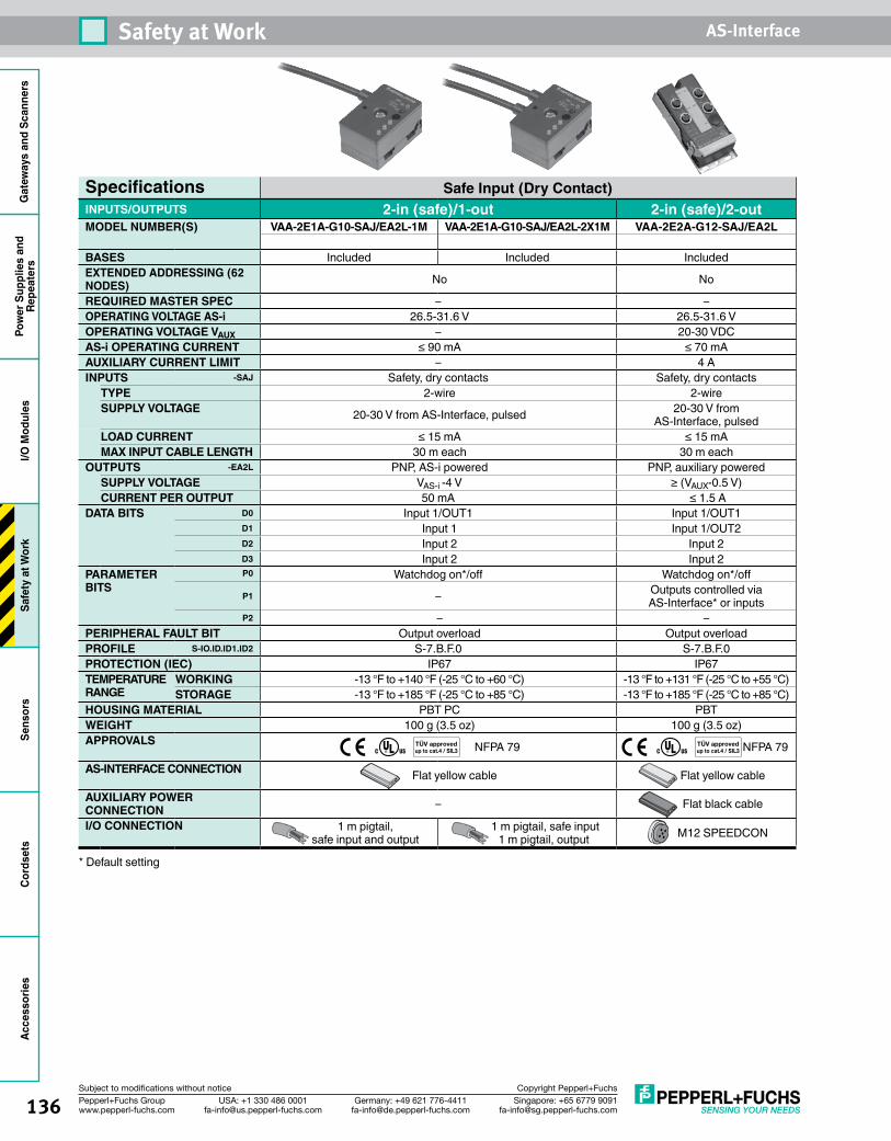
136 Singapore: +65 6779 [email protected]
USA: +1 330 486 [email protected]
Germany: +49 621 [email protected]
Pepperl+Fuchs Groupwww.pepperl-fuchs.com
Subject to modifications without notice Copyright Pepperl+Fuchs
Safety at Work AS-InterfaceG
atew
ays
and
Scan
ners
Pow
er S
uppl
ies
and
Repe
ater
sI/O
Mod
ules
Safe
ty a
t Wor
kSe
nsor
sCo
rdse
tsAc
cess
orie
s
Specifications Safe Input (Dry Contact)INPUTS/OUTPUTS 2-in (safe)/1-out 2-in (safe)/2-outMODEL NUMBER(S) VAA-2E1A-G10-SAJ/EA2L-1M VAA-2E1A-G10-SAJ/EA2L-2X1M VAA-2E2A-G12-SAJ/EA2L
BASES Included Included IncludedEXTENDED ADDRESSING (62 NODES) No No
REQUIRED MASTER SPEC – –OPERATING VOLTAGE AS-i 26.5-31.6 V 26.5-31.6 VOPERATING VOLTAGE VAUX – 20-30 VDCAS-i OPERATING CURRENT ≤ 90 mA ≤ 70 mAAUXILIARY CURRENT LIMIT – 4 AINPUTS -SAJ Safety, dry contacts Safety, dry contacts
TYPE 2-wire 2-wireSUPPLY VOLTAGE 20-30 V from AS-Interface, pulsed 20-30 V from
AS-Interface, pulsedLOAD CURRENT ≤ 15 mA ≤ 15 mAMAX INPUT CABLE LENGTH 30 m each 30 m each
OUTPUTS -EA2L PNP, AS-i powered PNP, auxiliary poweredSUPPLY VOLTAGE VAS-i -4 V ≥ (VAUX-0.5 V)CURRENT PER OUTPUT 50 mA ≤ 1.5 A
DATA BITS D0 Input 1/OUT1 Input 1/OUT1D1 Input 1 Input 1/OUT2D2 Input 2 Input 2D3 Input 2 Input 2
PARAMETER BITS
P0 Watchdog on*/off Watchdog on*/offP1 – Outputs controlled via
AS-Interface* or inputsP2 – –
PERIPHERAL FAULT BIT Output overload Output overloadPROFILE S-IO.ID.ID1.ID2 S-7.B.F.0 S-7.B.F.0PROTECTION (IEC) IP67 IP67TEMPERATURE RANGE
WORKING -13 °F to +140 °F (-25 °C to +60 °C) -13 °F to +131 °F (-25 °C to +55 °C)STORAGE -13 °F to +185 °F (-25 °C to +85 °C) -13 °F to +185 °F (-25 °C to +85 °C)
HOUSING MATERIAL PBT PC PBTWEIGHT 100 g (3.5 oz) 100 g (3.5 oz)APPROVALS NFPA 79 NFPA 79
AS-INTERFACE CONNECTION Flat yellow cable Flat yellow cable
AUXILIARY POWER CONNECTION – Flat black cable
I/O CONNECTION 1 m pigtail, safe input and output
1 m pigtail, safe input 1 m pigtail, output M12 SPEEDCON
* Default setting
TÜV approvedup to cat.4 / SIL3
TÜV approvedup to cat.4 / SIL3
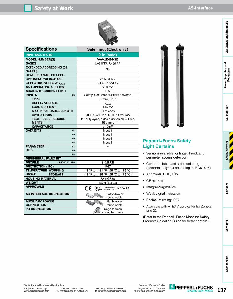
137Singapore: +65 6779 [email protected]
USA: +1 330 486 [email protected]
Germany: +49 621 [email protected]
Pepperl+Fuchs Groupwww.pepperl-fuchs.com
Subject to modifications without notice Copyright Pepperl+Fuchs
Safety at Work AS-Interface
Gat
eway
s an
d Sc
anne
rsPo
wer
Sup
plie
s an
d Re
peat
ers
I/O M
odul
esSa
fety
at W
ork
Sens
ors
Cord
sets
Acce
ssor
ies
Specifications Safe Input (Electronic)INPUTS/OUTPUTS 2-in (safe)MODEL NUMBER(S) VAA-2E-G4-SEBASES U-G1FFA, U-G1PPEXTENDED ADDRESSING (62 NODES) No
REQUIRED MASTER SPEC. –OPERATING VOLTAGE AS-i 26.5-31.6 VOPERATING VOLTAGE VAUX 21.4-27.6 VDCAS-i OPERATING CURRENT ≤ 30 mAAUXILIARY CURRENT LIMIT 2 AINPUTS -SE Safety, electronic auxiliary powered
TYPE 3-wire, PNPSUPPLY VOLTAGE VAUXLOAD CURRENT ≤ 45 mAMAX INPUT CABLE LENGTH 30 m eachSWITCH POINT OFF ≤ 5V/2 mA, ON ≥ 11 V/6 mATEST PULSE REQUIRE-MENTS
1% duty cycle, pulse duration max. 1 ms, 16 V min.
CAPACITANCE ≤ 10 nFDATA BITS D0 Input 1
D1 Input 1D2 Input 2D3 Input 2
PARAMETER BITS
P0 –P1 –P2 –
PERIPHERAL FAULT BIT –PROFILE S-IO.ID.ID1.ID2 S-0.B.F.EPROTECTION (IEC) IP67TEMPERATURE RANGE
WORKING -13 °F to +131 °F (-25 °C to +55 °C)STORAGE -13 °F to +185 °F (-25 °C to +85 °C)
HOUSING MATERIAL PA 6 GF30WEIGHT 180 g (6.3 oz)APPROVALS NFPA 79
AS-INTERFACE CONNECTION Flat yellow or round cable
AUXILIARY POWER CONNECTION
Flat black or round cable
I/O CONNECTION Cage tension spring terminals
TÜV approvedup to cat.4 / SIL3
Pepperl+Fuchs Safety Light Curtains• Versions available for finger, hand, and
perimeter access detection
• Control-reliable and self-monitoring (conform to Type 4 according to IEC61496)
• Approvals: CUL, TÜV
• CE marked
• Integral diagnostics
• Weak signal indication
• Enclosure rating: IP67
• Available with ATEX Approval for Ex Zone 2 and 22
(Refer to the Pepperl+Fuchs Machine Safety Products Selection Guide for further details.)
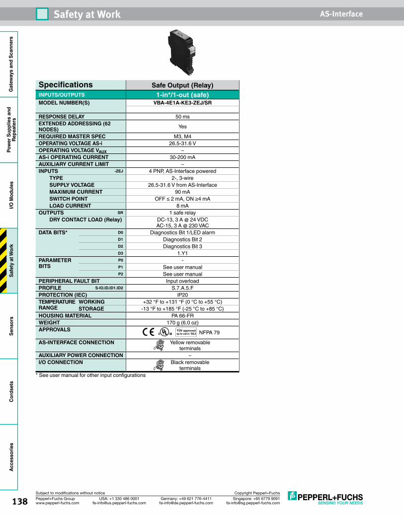
138 Singapore: +65 6779 [email protected]
USA: +1 330 486 [email protected]
Germany: +49 621 [email protected]
Pepperl+Fuchs Groupwww.pepperl-fuchs.com
Subject to modifications without notice Copyright Pepperl+Fuchs
Safety at Work AS-InterfaceG
atew
ays
and
Scan
ners
Pow
er S
uppl
ies
and
Repe
ater
sI/O
Mod
ules
Safe
ty a
t Wor
kSe
nsor
sCo
rdse
tsAc
cess
orie
s
Specifications Safe Output (Relay)INPUTS/OUTPUTS 1-in*/1-out (safe)MODEL NUMBER(S) VBA-4E1A-KE3-ZEJ/SR
RESPONSE DELAY 50 msEXTENDED ADDRESSING (62 NODES) Yes
REQUIRED MASTER SPEC M3, M4OPERATING VOLTAGE AS-i 26.5-31.6 VOPERATING VOLTAGE VAUX –AS-i OPERATING CURRENT 30-200 mAAUXILIARY CURRENT LIMIT –INPUTS -ZEJ 4 PNP, AS-Interface powered
TYPE 2-, 3-wireSUPPLY VOLTAGE 26.5-31.6 V from AS-InterfaceMAXIMUM CURRENT 90 mASWITCH POINT OFF ≤ 2 mA, ON ≥4 mALOAD CURRENT 8 mA
OUTPUTS SR 1 safe relayDRY CONTACT LOAD (Relay) DC-13, 3 A @ 24 VDC
AC-15, 3 A @ 230 VACDATA BITS* D0 Diagnostics Bit 1/LED alarm
D1 Diagnostics Bit 2D2 Diagnostics Bit 3D3 1.Y1
PARAMETER BITS
P0 -P1 See user manualP2 See user manual
PERIPHERAL FAULT BIT Input overloadPROFILE S-IO.ID.ID1.ID2 S.7.A.5.FPROTECTION (IEC) IP20TEMPERATURE RANGE
WORKING +32 °F to +131 °F (0 °C to +55 °C)STORAGE -13 °F to +185 °F (-25 °C to +85 °C)
HOUSING MATERIAL PA 66-FRWEIGHT 170 g (6.0 oz)APPROVALS NFPA 79
AS-INTERFACE CONNECTION Yellow removable terminals
AUXILIARY POWER CONNECTION –I/O CONNECTION Black removable
terminals* See user manual for other input configurations
TÜV approvedup to cat.4 / SIL3
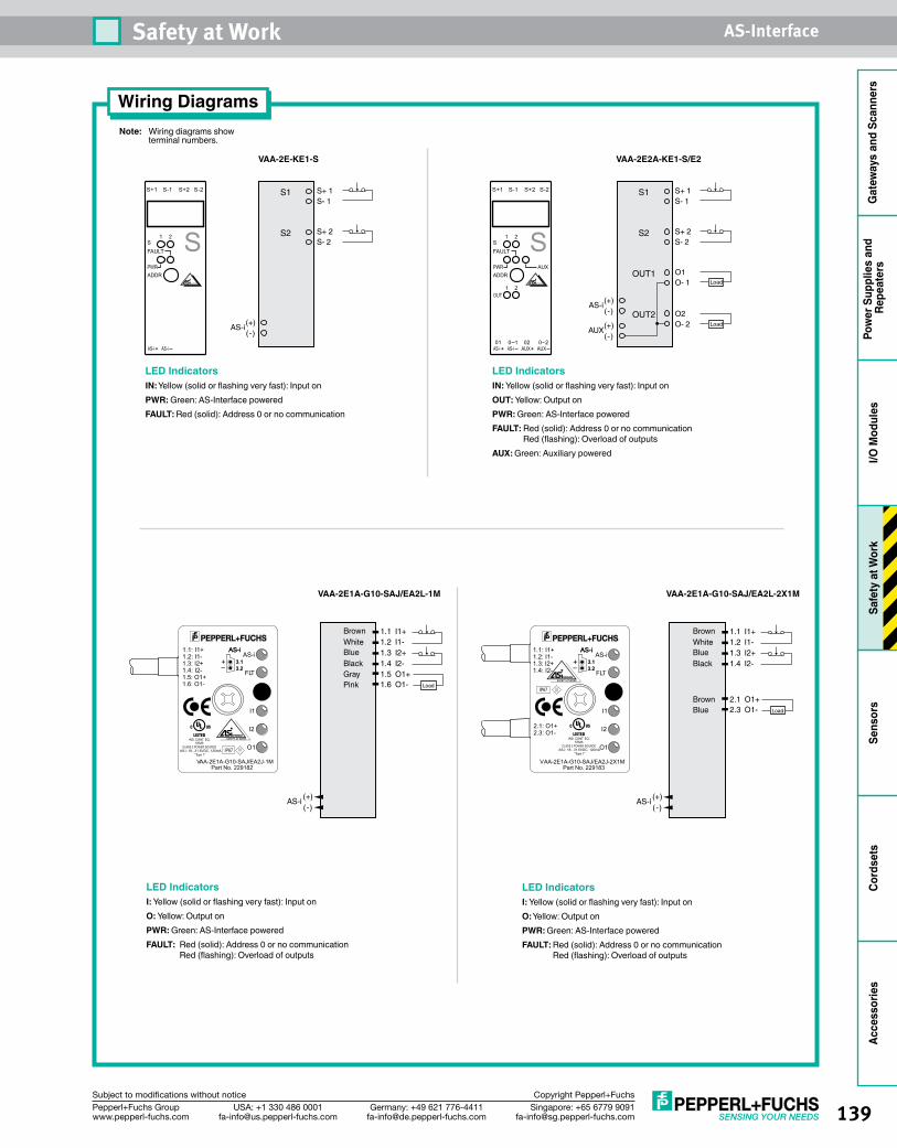
139Singapore: +65 6779 [email protected]
USA: +1 330 486 [email protected]
Germany: +49 621 [email protected]
Pepperl+Fuchs Groupwww.pepperl-fuchs.com
Subject to modifications without notice Copyright Pepperl+Fuchs
Safety at Work AS-Interface
Gat
eway
s an
d Sc
anne
rsPo
wer
Sup
plie
s an
d Re
peat
ers
I/O M
odul
esSa
fety
at W
ork
Sens
ors
Cord
sets
Acce
ssor
ies
Wiring DiagramsNote: Wiring diagrams show terminal numbers.
VAA-2E-KE1-S
S+ 1S- 1
S1
S+ 2S- 2
S2
(+)(-)
AS-i
+
1 2SFAULT
PWRADDR
AS-i AS-i
S
S+1 S-1 S+2 S-2
+ +
1
1
2
2
SFAULT
AUXPWRADDR
OUT
01AS-i AS-i
0 1 02AUX AUX
0 2
S
S+1 S-1 S+2 S-2
VAA-2E2A-KE1-S/E2
S+ 1S- 1
S1
S+ 2S- 2
S2
OUT1
OUT2
O1O- 1
O2O- 2
Load
Load(+)(-)
AUX
(+)(-)
AS-i
LED IndicatorsIN: Yellow (solid or flashing very fast): Input onPWR: Green: AS-Interface poweredFAULT: Red (solid): Address 0 or no communication
LED IndicatorsIN: Yellow (solid or flashing very fast): Input onOUT: Yellow: Output onPWR: Green: AS-Interface poweredFAULT: Red (solid): Address 0 or no communication
Red (flashing): Overload of outputsAUX: Green: Auxiliary powered
VAA-2E1A-G10-SAJ/EA2L-1M VAA-2E1A-G10-SAJ/EA2L-2X1M
LED IndicatorsI: Yellow (solid or flashing very fast): Input onO: Yellow: Output onPWR: Green: AS-Interface poweredFAULT: Red (solid): Address 0 or no communication
Red (flashing): Overload of outputs
LED IndicatorsI: Yellow (solid or flashing very fast): Input onO: Yellow: Output onPWR: Green: AS-Interface poweredFAULT: Red (solid): Address 0 or no communication
Red (flashing): Overload of outputs
1.1 I1+1.2 I1-1.3 I2+1.4 I2-1.5 O1+
(+)(-)
AS-i
1.6 O1- Load
Brown White Blue Black Gray Pink
VAA-2E1A-G10-SAJ/EA2J-1MPart No. 229182
I1
O1
I2
CLASS 2 POWER SOURCE
IND. CONT. EQ.57M3
AS-i
3.13.2
AS-i
3.13.2
AS-i
FLT+–
1.1: I1+1.2: I1-1.3: I2+1.4: I2-1.5: O1+1.6: O1-
“Type 1”AS-i: 18...31.6VDC, 120mA IP67
1.1 I1+1.2 I1-1.3 I2+1.4 I2-
2.1 O1+
(+)(-)
AS-i
2.3 O1- Load
Brown White Blue Black
Brown Blue
VAA-2E1A-G10-SAJ/EA2J-2X1MPart No. 229183
I1
O1
I2
CLASS 2 POWER SOURCE
IND. CONT. EQ.57M3
AS-i
3.13.2
AS-i
3.13.2
AS-i
FLT+–
1.1: I1+1.2: I1-1.3: I2+1.4: I2-
2.1: O1+2.3: O1-
“Type 1”AS-i: 18...31.6VDC, 120mA
IP67
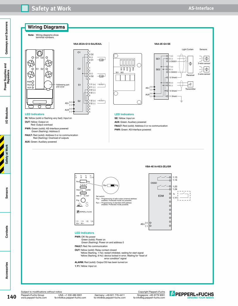
140 Singapore: +65 6779 [email protected]
USA: +1 330 486 [email protected]
Germany: +49 621 [email protected]
Pepperl+Fuchs Groupwww.pepperl-fuchs.com
Subject to modifications without notice Copyright Pepperl+Fuchs
Safety at Work AS-InterfaceG
atew
ays
and
Scan
ners
Pow
er S
uppl
ies
and
Repe
ater
sI/O
Mod
ules
Safe
ty a
t Wor
kSe
nsor
sCo
rdse
tsAc
cess
orie
s
Wiring DiagramsNote: Wiring diagrams show terminal numbers.
1 (+)2 (-) 3 OSSD1
Light Curtain Sensors
SE1
7 (+)6 (-) 5 OSSD2
SE2
8 (+)9 (-)
12 Shield
10 Shield
11 Shield
3-wire sensor
Receiver 3-wire sensor
Transmitter
(+)(-)
AUX
(+)(-)
AS-i1 I1 (+)2 I1 (-)3 I2 (+)4 I2 (-)5
1 I2 (+)2 I2 (-)3 4 5
12 O23 (-)4 O15
1 2 3 (-)4 O25
Load
Load
O1
O2
S1
S2
(+)(-)
AUX
(+)(-)
AS-i
VAA-2E2A-G12-SAJ/EA2L
VBA-4E1A-KE3-ZEJ/SR
4
3
1
25
43
1
2
5
43
1
2
54
3
1
25
O1 O2
S1 S2
PWR
AUXAddressing jackand cover
FAULT
LED IndicatorsIN: Yellow (solid or flashing very fast): Input onOUT: Yellow: Output on
Red: Output overloadPWR: Green (solid): AS-Interface powered
Green (flashing): Address 0FAULT: Red (solid): Address 0 or no communication
Red (flashing): Overload of outputsAUX: Green: Auxiliary powered
SE1
SE2
AUX
FAUL
TPW
R
SE1 SE2
LED IndicatorsSE: Yellow: Input onAUX: Green: Auxiliary poweredFAULT: Red (solid): Address 0 or no communicationPWR: Green: AS-Interface powered
VAA-2E-G4-SE
I1
Run Prg
Prg
I- I+ I+ I+
+
I2 I3 1.Y1
I1 I2 I3 1.Y1
FAULT ALARM
OUTPWR
AS-i AS-i1.13 1.14 1.23 1.24
PEPPERL+FUCHS
S
Run Prg
Set switch:Prg = Programming of safe output channel address
enabled. Protected mode not possible.Run = Programming of standard A/B address
enabled. Protected mode possible.
1.131.14
1.231.24
1.Y1
OSSD
EDMI+
(+)(-)
AS-i
LED IndicatorsPWR: Off: No power
Green (solid): Power on Green (flashing): Power on and address 0
FAULT: Red: No communicationOUT: Yellow (solid): Relay contact closed
Yellow (flashing, 1 Hz): restart inhibited, waiting for start signal Yellow (flashing, 8 Hz): device locked in error, Waiting for “reset of
error condition” signalALARM: Red (solid): Output D0 has been turned on1.Y1: Yellow: Input on
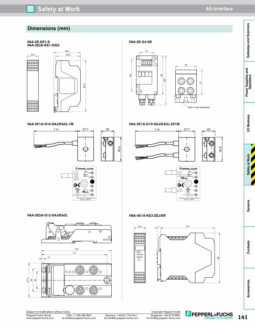
141Singapore: +65 6779 [email protected]
USA: +1 330 486 [email protected]
Germany: +49 621 [email protected]
Pepperl+Fuchs Groupwww.pepperl-fuchs.com
Subject to modifications without notice Copyright Pepperl+Fuchs
Safety at Work AS-Interface
Gat
eway
s an
d Sc
anne
rsPo
wer
Sup
plie
s an
d Re
peat
ers
I/O M
odul
esSa
fety
at W
ork
Sens
ors
Cord
sets
Acce
ssor
ies
Dimensions (mm)
VAA-2E1A-G10-SAJ/EA2L-1M
VAA-2E-KE1-S VAA-2E2A-KE1-S/E2
VAA-2E-G4-SE
VBA-4E1A-KE3-ZEJ/SR
99.6
48.5
50.5
22.5
Base is sold separately
31
66 8010
2
51
45
VAA-2E2A-G12-SAJ/EA2L
57.4
39 30
118
111
4.1
22.5 7 107
99
VAA-2E1A-G10-SAJ/EA2L-2X1M27.7 22
40.5
1 m 27.7 22
40.5
1 m
VAA-2E1A-G10-SAJ/EA2J-2X1MPart No. 229183
I1
O1
I2
CLASS 2 POWER SOURCE
IND. CONT. EQ.57M3
AS-i
3.13.2
AS-i
3.13.2
AS-i
FLT+–
1.1: I1+1.2: I1-1.3: I2+1.4: I2-
2.1: O1+2.3: O1-
“Type 1”AS-i: 18...31.6VDC, 120mA
IP67
VAA-2E1A-G10-SAJ/EA2J-1MPart No. 229182
I1
O1
I2
CLASS 2 POWER SOURCE
IND. CONT. EQ.57M3
AS-i
3.13.2
AS-i
3.13.2
AS-i
FLT+–
1.1: I1+1.2: I1-1.3: I2+1.4: I2-1.5: O1+1.6: O1-
“Type 1”AS-i: 18...31.6VDC, 120mA IP67
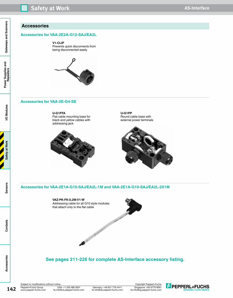
142 Singapore: +65 6779 [email protected]
USA: +1 330 486 [email protected]
Germany: +49 621 [email protected]
Pepperl+Fuchs Groupwww.pepperl-fuchs.com
Subject to modifications without notice Copyright Pepperl+Fuchs
Safety at Work AS-InterfaceG
atew
ays
and
Scan
ners
Pow
er S
uppl
ies
and
Repe
ater
sI/O
Mod
ules
Safe
ty a
t Wor
kSe
nsor
sCo
rdse
tsAc
cess
orie
s
Accessories
V1-CLIPPrevents quick disconnects from being disconnected easily
Accessories for VAA-2E2A-G12-SAJ/EA2L
Accessories for VAA-2E-G4-SE
U-G1FFAFlat cable mounting base for black and yellow cables withaddressing jack
U-G1PPRound cable base with external power terminals
See pages 211-226 for complete AS-Interface accessory listing.
Accessories for VAA-2E1A-G10-SAJ/EA2L-1M and VAA-2E1A-G10-SAJ/EA2L-2X1M
VAZ-PK-FK-0,2M-V1-WAddressing cable for all G10 style modules that attach only to the flat cable

143Singapore: +65 6779 [email protected]
USA: +1 330 486 [email protected]
Germany: +49 621 [email protected]
Pepperl+Fuchs Groupwww.pepperl-fuchs.com
Subject to modifications without notice Copyright Pepperl+Fuchs
Safety at Work AS-Interface
Gat
eway
s an
d Sc
anne
rsPo
wer
Sup
plie
s an
d Re
peat
ers
I/O M
odul
esSa
fety
at W
ork
Sens
ors
Cord
sets
Acce
ssor
ies
Emergency StopsSafety Solutions• Connects directly to AS-Interface cable• Illuminated and nonilluminated
versions• Field mount and panel mount housings
available• Field mount e-stops with M12 quick
disconnect• Twist or pull to release• Completely powered off AS-Interface
Emergency Stop OverviewThese emergency stops connect directly to the AS-Interface cable for easy mounting. Because the AS-Interface safety module is integrated into the e-stop itself, the wiring between the two is eliminated. This reduces the overall wiring/complexity of your machine.
The four versions available are illuminated panel mount, nonilluminated panel mount, illuminated field mount, and nonilluminated field mount.
See page 145 for Emergency Stop wiring and dimensions.
1.5 m pigtail
Addressing jack Emergency stop legend plate
LED
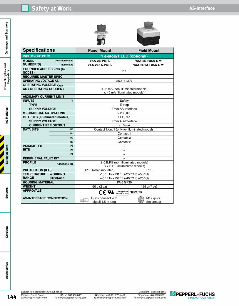
144 Singapore: +65 6779 [email protected]
USA: +1 330 486 [email protected]
Germany: +49 621 [email protected]
Pepperl+Fuchs Groupwww.pepperl-fuchs.com
Subject to modifications without notice Copyright Pepperl+Fuchs
Safety at Work AS-InterfaceG
atew
ays
and
Scan
ners
Pow
er S
uppl
ies
and
Repe
ater
sI/O
Mod
ules
Safe
ty a
t Wor
kSe
nsor
sCo
rdse
tsAc
cess
orie
s
Specifications Panel Mount Field MountINPUTS/OUTPUTS 1 e-stop/1 LED (optional)MODEL NUMBER(S)
Non-illuminated VAA-2E-PM-S VAA-2E-F85A-S-V1Illuminated VAA-2E1A-PM-S VAA-2E1A-F85A-S-V1
EXTENDED ADDRESSING (62 NODES) No
REQUIRED MASTER SPEC –OPERATING VOLTAGE AS-i 26.5-31.6 VOPERATING VOLTAGE VAUX –AS-i OPERATING CURRENT ≤ 25 mA (non-illuminated models)
≤ 40 mA (illuminated models)AUXILIARY CURRENT LIMIT –INPUTS -S Safety
TYPE E-stopSUPPLY VOLTAGE From AS-Interface
MECHANICAL ACTIVATIONS > 250,000OUTPUTS (Illuminated models) LED, red
SUPPLY VOLTAGE From AS-InterfaceCURRENT PER OUTPUT ≤ 15 mA
DATA BITS D0 Contact 1/out 1 (only for illuminated models)D1 Contact 1D2 Contact 2D3 Contact 2
PARAMETER BITS
P0 –P1 –P2 –
PERIPHERAL FAULT BIT –PROFILE S-IO.ID.ID1.ID2 S-0.B.F.E (non-illuminated models)
S-7.B.F.E (illuminated models)PROTECTION (IEC) IP65 (when mounted) IP65TEMPERATURE RANGE
WORKING -13 °F to +131 °F (-25 °C to +55 °C)STORAGE -40 °F to +158 °F (-40 °C to +70 °C)
HOUSING MATERIAL PA 6 GF30WEIGHT 60 g (2 oz) 195 g (7 oz)APPROVALS NFPA 79
AS-INTERFACE CONNECTION Quick connect with pigtail 1.5 m long
M12 quick disconnect
TÜV approvedup to cat.4 / SIL3
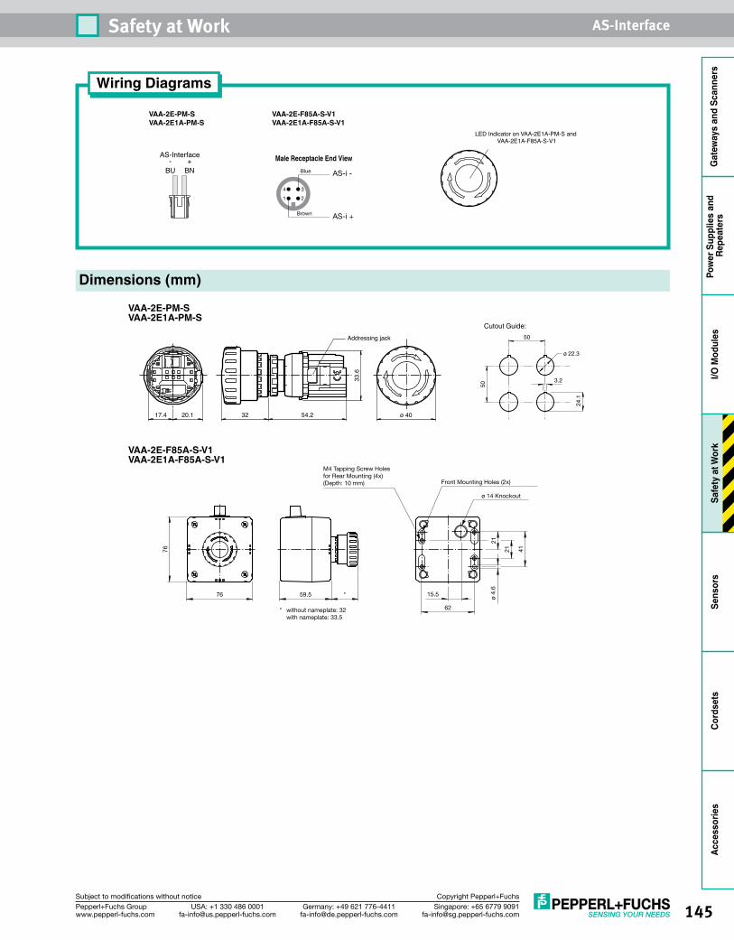
145Singapore: +65 6779 [email protected]
USA: +1 330 486 [email protected]
Germany: +49 621 [email protected]
Pepperl+Fuchs Groupwww.pepperl-fuchs.com
Subject to modifications without notice Copyright Pepperl+Fuchs
Safety at Work AS-Interface
Gat
eway
s an
d Sc
anne
rsPo
wer
Sup
plie
s an
d Re
peat
ers
I/O M
odul
esSa
fety
at W
ork
Sens
ors
Cord
sets
Acce
ssor
ies
Wiring Diagrams
VAA-2E-F85A-S-V1 VAA-2E1A-F85A-S-V1
1 2
4 3
Brown
Blue
AS-i +
AS-i -
Male Receptacle End View
VAA-2E-PM-S VAA-2E1A-PM-S
BU
AS-Interface
BN- +
LED Indicator on VAA-2E1A-PM-S and VAA-2E1A-F85A-S-V1
VAA-2E-PM-S VAA-2E1A-PM-S
VAA-2E-F85A-S-V1 VAA-2E1A-F85A-S-V1
17.4 20.1 32 54.2 ø 40
33.6
Addressing jack 50
ø 22.3
Cutout Guide:
50
3.2
24.1
Dimensions (mm)
76
76
21
15.5
62
ø 14 Knockout
Front Mounting Holes (2x)
M4 Tapping Screw Holes for Rear Mounting (4x)(Depth: 10 mm)
* without nameplate: 32 with nameplate: 33.5
59.5 *
21
41
ø 4.
6
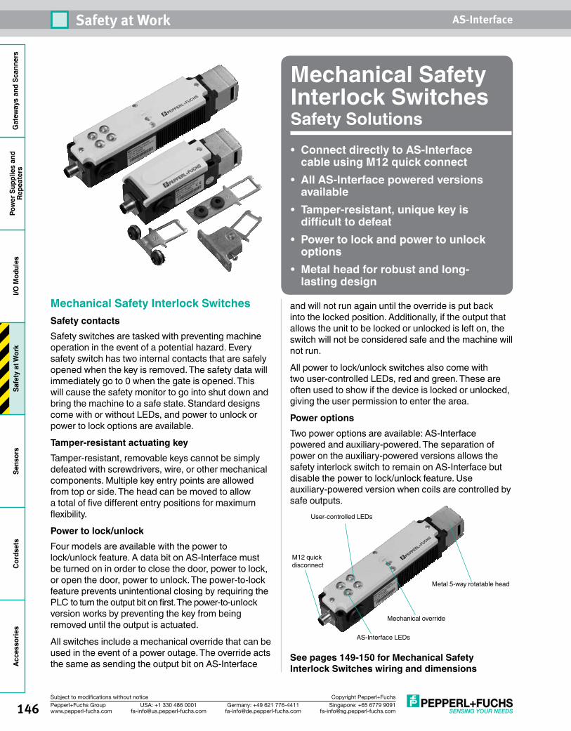
146 Singapore: +65 6779 [email protected]
USA: +1 330 486 [email protected]
Germany: +49 621 [email protected]
Pepperl+Fuchs Groupwww.pepperl-fuchs.com
Subject to modifications without notice Copyright Pepperl+Fuchs
Safety at Work AS-InterfaceG
atew
ays
and
Scan
ners
Pow
er S
uppl
ies
and
Repe
ater
sI/O
Mod
ules
Safe
ty a
t Wor
kSe
nsor
sCo
rdse
tsAc
cess
orie
s
Mechanical Safety Interlock SwitchesSafety Solutions• Connect directly to AS-Interface
cable using M12 quick connect• All AS-Interface powered versions
available• Tamper-resistant, unique key is
difficult to defeat• Power to lock and power to unlock
options• Metal head for robust and long-
lasting design
Mechanical Safety Interlock SwitchesSafety contactsSafety switches are tasked with preventing machine operation in the event of a potential hazard. Every safety switch has two internal contacts that are safely opened when the key is removed. The safety data will immediately go to 0 when the gate is opened. This will cause the safety monitor to go into shut down and bring the machine to a safe state. Standard designs come with or without LEDs, and power to unlock or power to lock options are available.
Tamper-resistant actuating keyTamper-resistant, removable keys cannot be simply defeated with screwdrivers, wire, or other mechanical components. Multiple key entry points are allowed from top or side. The head can be moved to allow a total of five different entry positions for maximum flexibility.
Power to lock/unlockFour models are available with the power to lock/unlock feature. A data bit on AS-Interface must be turned on in order to close the door, power to lock, or open the door, power to unlock. The power-to-lock feature prevents unintentional closing by requiring the PLC to turn the output bit on first. The power-to-unlock version works by preventing the key from being removed until the output is actuated.
All switches include a mechanical override that can be used in the event of a power outage. The override acts the same as sending the output bit on AS-Interface
and will not run again until the override is put back into the locked position. Additionally, if the output that allows the unit to be locked or unlocked is left on, the switch will not be considered safe and the machine will not run.
All power to lock/unlock switches also come with two user-controlled LEDs, red and green. These are often used to show if the device is locked or unlocked, giving the user permission to enter the area.
Power optionsTwo power options are available: AS-Interface powered and auxiliary-powered. The separation of power on the auxiliary-powered versions allows the safety interlock switch to remain on AS-Interface but disable the power to lock/unlock feature. Use auxiliary-powered version when coils are controlled by safe outputs.
See pages 149-150 for Mechanical Safety Interlock Switches wiring and dimensions
User-controlled LEDs
AS-Interface LEDs
Mechanical override
Metal 5-way rotatable head
M12 quick disconnect
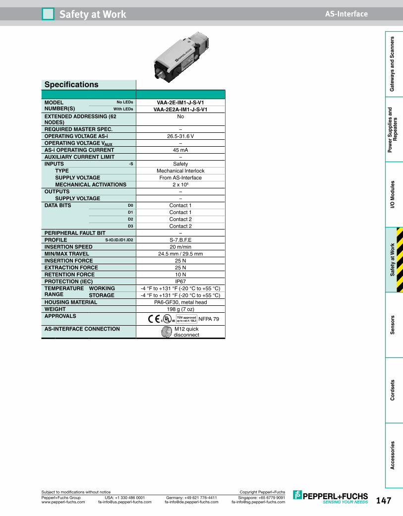
147Singapore: +65 6779 [email protected]
USA: +1 330 486 [email protected]
Germany: +49 621 [email protected]
Pepperl+Fuchs Groupwww.pepperl-fuchs.com
Subject to modifications without notice Copyright Pepperl+Fuchs
Safety at Work AS-Interface
Gat
eway
s an
d Sc
anne
rsPo
wer
Sup
plie
s an
d Re
peat
ers
I/O M
odul
esSa
fety
at W
ork
Sens
ors
Cord
sets
Acce
ssor
ies
Specifications
MODEL NUMBER(S)
No LEDs VAA-2E-IM1-J-S-V1With LEDs VAA-2E2A-IM1-J-S-V1
EXTENDED ADDRESSING (62 NODES)
No
REQUIRED MASTER SPEC. –OPERATING VOLTAGE AS-i 26.5-31.6 VOPERATING VOLTAGE VAUX –AS-i OPERATING CURRENT 45 mAAUXILIARY CURRENT LIMIT –INPUTS -S Safety
TYPE Mechanical InterlockSUPPLY VOLTAGE From AS-InterfaceMECHANICAL ACTIVATIONS 2 x 10⁶
OUTPUTS –SUPPLY VOLTAGE –
DATA BITS D0 Contact 1D1 Contact 1D2 Contact 2D3 Contact 2
PERIPHERAL FAULT BIT –PROFILE S-IO.ID.ID1.ID2 S-7.B.F.EINSERTION SPEED 20 m/minMIN/MAX TRAVEL 24.5 mm / 29.5 mmINSERTION FORCE 25 NEXTRACTION FORCE 25 NRETENTION FORCE 10 NPROTECTION (IEC) IP67TEMPERATURE RANGE
WORKING -4 °F to +131 °F (-20 °C to +55 °C)STORAGE -4 °F to +131 °F (-20 °C to +55 °C)
HOUSING MATERIAL PA6-GF30, metal headWEIGHT 198 g (7 oz)APPROVALS NFPA 79
AS-INTERFACE CONNECTION M12 quick disconnect
TÜV approvedup to cat.4 / SIL3
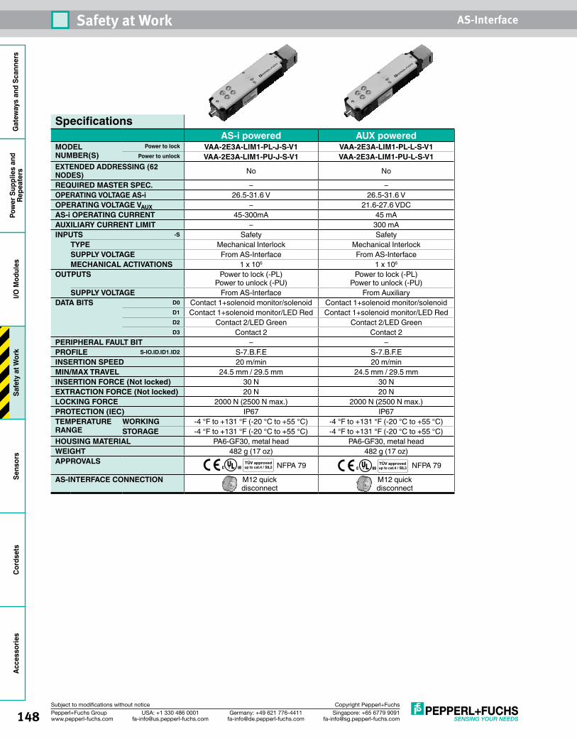
148 Singapore: +65 6779 [email protected]
USA: +1 330 486 [email protected]
Germany: +49 621 [email protected]
Pepperl+Fuchs Groupwww.pepperl-fuchs.com
Subject to modifications without notice Copyright Pepperl+Fuchs
Safety at Work AS-InterfaceG
atew
ays
and
Scan
ners
Pow
er S
uppl
ies
and
Repe
ater
sI/O
Mod
ules
Safe
ty a
t Wor
kSe
nsor
sCo
rdse
tsAc
cess
orie
s
SpecificationsAS-i powered AUX powered
MODEL NUMBER(S)
Power to lock VAA-2E3A-LIM1-PL-J-S-V1 VAA-2E3A-LIM1-PL-L-S-V1Power to unlock VAA-2E3A-LIM1-PU-J-S-V1 VAA-2E3A-LIM1-PU-L-S-V1
EXTENDED ADDRESSING (62 NODES) No No
REQUIRED MASTER SPEC. – –OPERATING VOLTAGE AS-i 26.5-31.6 V 26.5-31.6 VOPERATING VOLTAGE VAUX – 21.6-27.6 VDCAS-i OPERATING CURRENT 45-300mA 45 mAAUXILIARY CURRENT LIMIT – 300 mAINPUTS -S Safety Safety
TYPE Mechanical Interlock Mechanical InterlockSUPPLY VOLTAGE From AS-Interface From AS-InterfaceMECHANICAL ACTIVATIONS 1 x 10⁶ 1 x 10⁶
OUTPUTS Power to lock (-PL) Power to unlock (-PU)
Power to lock (-PL) Power to unlock (-PU)
SUPPLY VOLTAGE From AS-Interface From AuxiliaryDATA BITS D0 Contact 1+solenoid monitor/solenoid Contact 1+solenoid monitor/solenoid
D1 Contact 1+solenoid monitor/LED Red Contact 1+solenoid monitor/LED RedD2 Contact 2/LED Green Contact 2/LED GreenD3 Contact 2 Contact 2
PERIPHERAL FAULT BIT – –PROFILE S-IO.ID.ID1.ID2 S-7.B.F.E S-7.B.F.EINSERTION SPEED 20 m/min 20 m/minMIN/MAX TRAVEL 24.5 mm / 29.5 mm 24.5 mm / 29.5 mmINSERTION FORCE (Not locked) 30 N 30 NEXTRACTION FORCE (Not locked) 20 N 20 NLOCKING FORCE 2000 N (2500 N max.) 2000 N (2500 N max.)PROTECTION (IEC) IP67 IP67TEMPERATURE RANGE
WORKING -4 °F to +131 °F (-20 °C to +55 °C) -4 °F to +131 °F (-20 °C to +55 °C)STORAGE -4 °F to +131 °F (-20 °C to +55 °C) -4 °F to +131 °F (-20 °C to +55 °C)
HOUSING MATERIAL PA6-GF30, metal head PA6-GF30, metal headWEIGHT 482 g (17 oz) 482 g (17 oz)APPROVALS NFPA 79 NFPA 79
AS-INTERFACE CONNECTION M12 quick disconnect
M12 quick disconnect
TÜV approvedup to cat.4 / SIL3
TÜV approvedup to cat.4 / SIL3
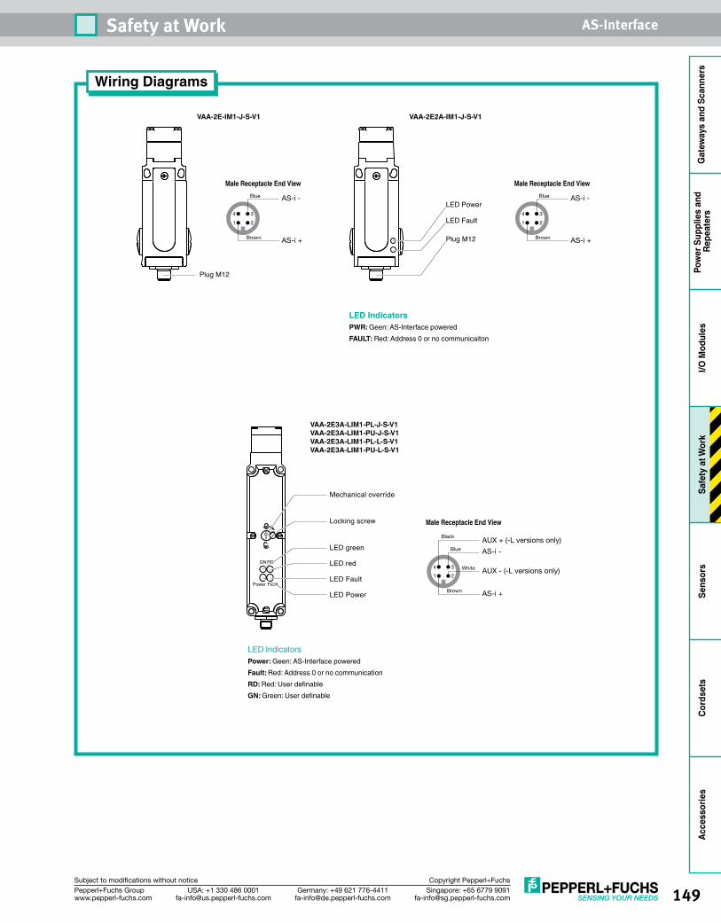
149Singapore: +65 6779 [email protected]
USA: +1 330 486 [email protected]
Germany: +49 621 [email protected]
Pepperl+Fuchs Groupwww.pepperl-fuchs.com
Subject to modifications without notice Copyright Pepperl+Fuchs
Safety at Work AS-Interface
Gat
eway
s an
d Sc
anne
rsPo
wer
Sup
plie
s an
d Re
peat
ers
I/O M
odul
esSa
fety
at W
ork
Sens
ors
Cord
sets
Acce
ssor
ies
Wiring Diagrams
Mechanical override
Locking screw
LED Power
LED Fault
LED green
LED redGNRD
Power Fault
Plug M12
LED Fault
LED Power
Plug M12
LED IndicatorsPWR: Geen: AS-Interface poweredFAULT: Red: Address 0 or no communicaiton
LED IndicatorsPower: Geen: AS-Interface poweredFault: Red: Address 0 or no communicationRD: Red: User definableGN: Green: User definable
1 2
4 3
Brown
Blue
White
Black
AS-i +
AS-i -
AUX + (-L versions only)
AUX - (-L versions only)
Male Receptacle End View
1 2
4 3
Brown
Blue
AS-i +
AS-i -
Male Receptacle End View
1 2
4 3
Brown
Blue
AS-i +
AS-i -
Male Receptacle End View
VAA-2E2A-IM1-J-S-V1VAA-2E-IM1-J-S-V1
VAA-2E3A-LIM1-PL-J-S-V1VAA-2E3A-LIM1-PU-J-S-V1VAA-2E3A-LIM1-PL-L-S-V1VAA-2E3A-LIM1-PU-L-S-V1
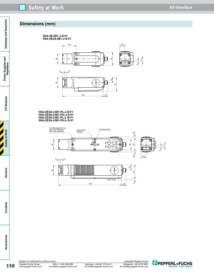
150 Singapore: +65 6779 [email protected]
USA: +1 330 486 [email protected]
Germany: +49 621 [email protected]
Pepperl+Fuchs Groupwww.pepperl-fuchs.com
Subject to modifications without notice Copyright Pepperl+Fuchs
Safety at Work AS-InterfaceG
atew
ays
and
Scan
ners
Pow
er S
uppl
ies
and
Repe
ater
sI/O
Mod
ules
Safe
ty a
t Wor
kSe
nsor
sCo
rdse
tsAc
cess
orie
s
for M5 length 35 mmISO 1207 (DIN 84)ISO 4762 (DIN912)
Mechanical release
Locking screw30
3.5
403.
5
4
6
10
3030
4 4
190 13
16
423
GN
RD
Powe
rFA
ULT
4
9
16
4016
42
123 13
4 4
41.5
3030
Dimensions (mm)
VAA-2E-IM1-J-S-V1VAA-2E2A-IM1-J-S-V1
VAA-2E3A-LIM1-PL-J-S-V1VAA-2E3A-LIM1-PU-J-S-V1VAA-2E3A-LIM1-PL-L-S-V1VAA-2E3A-LIM1-PU-L-S-V1
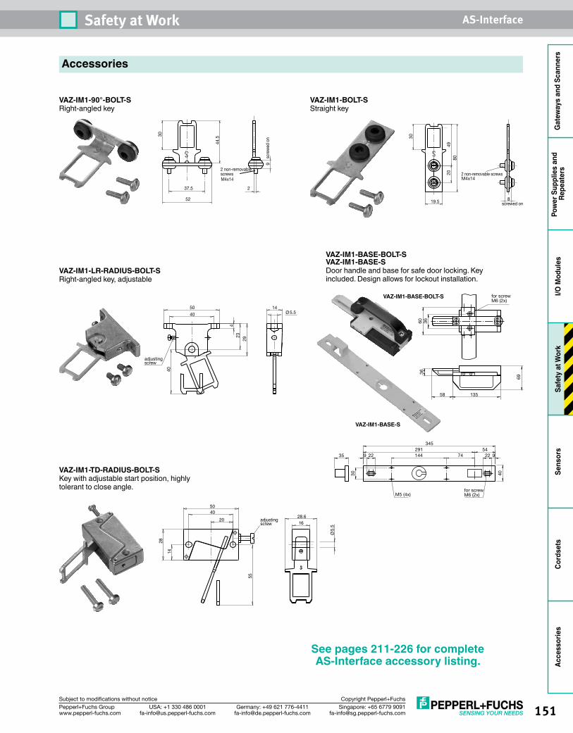
151Singapore: +65 6779 [email protected]
USA: +1 330 486 [email protected]
Germany: +49 621 [email protected]
Pepperl+Fuchs Groupwww.pepperl-fuchs.com
Subject to modifications without notice Copyright Pepperl+Fuchs
Safety at Work AS-Interface
Gat
eway
s an
d Sc
anne
rsPo
wer
Sup
plie
s an
d Re
peat
ers
I/O M
odul
esSa
fety
at W
ork
Sens
ors
Cord
sets
Acce
ssor
ies
Accessories
VAZ-IM1-90°-BOLT-SRight-angled key
VAZ-IM1-BOLT-SStraight key
VAZ-IM1-LR-RADIUS-BOLT-SRight-angled key, adjustable
VAZ-IM1-BASE-BOLT-SVAZ-IM1-BASE-SDoor handle and base for safe door locking. Key included. Design allows for lockout installation.
VAZ-IM1-TD-RADIUS-BOLT-SKey with adjustable start position, highly tolerant to close angle.
scre
wed
on
2 non-removablescrewsM4x14
2
9
37.5
52
30
44.5
screwed on
2 non-removable screws M4x14
819.5
8049
20
30
adjustingscrew
423
29
4050
Ø 5.514
40
for screw M6 (2x)
36
58 135
6036
69
for screw M6 (2x)
22 99 22
M5 (4x)
30 40
144 74291 54
345
35
adjustingscrew
20
4050
14
28
55
1628.6
Ø5.
5
See pages 211-226 for complete AS-Interface accessory listing.
VAZ-IM1-BASE-BOLT-S
VAZ-IM1-BASE-S
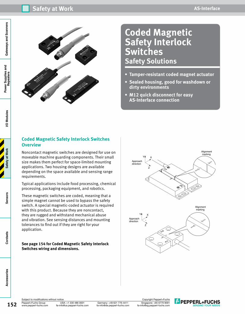
152 Singapore: +65 6779 [email protected]
USA: +1 330 486 [email protected]
Germany: +49 621 [email protected]
Pepperl+Fuchs Groupwww.pepperl-fuchs.com
Subject to modifications without notice Copyright Pepperl+Fuchs
Safety at Work AS-InterfaceG
atew
ays
and
Scan
ners
Pow
er S
uppl
ies
and
Repe
ater
sI/O
Mod
ules
Safe
ty a
t Wor
kSe
nsor
sCo
rdse
tsAc
cess
orie
s
Coded Magnetic Safety Interlock SwitchesSafety Solutions• Tamper-resistant coded magnet actuator• Sealed housing, good for washdown or
dirty environments• M12 quick disconnect for easy
AS-Interface connection
Coded Magnetic Safety Interlock Switches OverviewNoncontact magnetic switches are designed for use on moveable machine guarding components. Their small size makes them perfect for space-limited mounting applications. Two housing designs are available depending on the space available and sensing range requirements.
Typical applications include food processing, chemical processing, packaging equipment, and robotics.
These magnetic switches are coded, meaning that a simple magnet cannot be used to bypass the safety switch. A special magnetic-coded actuator is required with this product. Because they are noncontact, they are rugged and withstand mechanical abuse and vibration. See sensing distances and mounting tolerances to find out if they are right for your application.
See page 154 for Coded Magnetic Safety Interlock Switches wiring and dimensions.
Alignmentmarking
Approachdirection
XY
Z
Alignmentmarking
Approachdirection
XY
Z
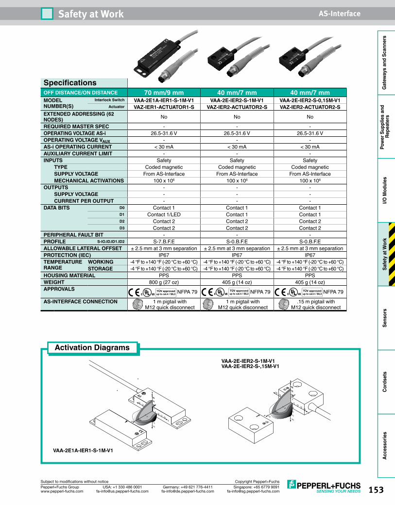
153Singapore: +65 6779 [email protected]
USA: +1 330 486 [email protected]
Germany: +49 621 [email protected]
Pepperl+Fuchs Groupwww.pepperl-fuchs.com
Subject to modifications without notice Copyright Pepperl+Fuchs
Safety at Work AS-Interface
Gat
eway
s an
d Sc
anne
rsPo
wer
Sup
plie
s an
d Re
peat
ers
I/O M
odul
esSa
fety
at W
ork
Sens
ors
Cord
sets
Acce
ssor
ies
SpecificationsOFF DISTANCE/ON DISTANCE 70 mm/9 mm 40 mm/7 mm 40 mm/7 mmMODEL NUMBER(S)
Interlock Switch VAA-2E1A-IER1-S-1M-V1 VAA-2E-IER2-S-1M-V1 VAA-2E-IER2-S-0,15M-V1Actuator VAZ-IER1-ACTUATOR1-S VAZ-IER2-ACTUATOR2-S VAZ-IER2-ACTUATOR2-S
EXTENDED ADDRESSING (62 NODES) No No No
REQUIRED MASTER SPEC - - -OPERATING VOLTAGE AS-i 26.5-31.6 V 26.5-31.6 V 26.5-31.6 VOPERATING VOLTAGE VAUX - - -AS-i OPERATING CURRENT < 30 mA < 30 mA < 30 mAAUXILIARY CURRENT LIMIT - - -INPUTS Safety Safety Safety
TYPE Coded magnetic Coded magnetic Coded magneticSUPPLY VOLTAGE From AS-Interface From AS-Interface From AS-InterfaceMECHANICAL ACTIVATIONS 100 x 106 100 x 106 100 x 106
OUTPUTS - - -SUPPLY VOLTAGE - - -CURRENT PER OUTPUT - - -
DATA BITS D0 Contact 1 Contact 1 Contact 1D1 Contact 1/LED Contact 1 Contact 1D2 Contact 2 Contact 2 Contact 2D3 Contact 2 Contact 2 Contact 2
PERIPHERAL FAULT BIT - - -PROFILE S-IO.ID.ID1.ID2 S-7.B.F.E S-0.B.F.E S-0.B.F.EALLOWABLE LATERAL OFFSET ± 2.5 mm at 3 mm separation ± 2.5 mm at 3 mm separation ± 2.5 mm at 3 mm separationPROTECTION (IEC) IP67 IP67 IP67TEMPERATURE RANGE
WORKING -4 °F to +140 °F (-20 °C to +60 °C) -4 °F to +140 °F (-20 °C to +60 °C) -4 °F to +140 °F (-20 °C to +60 °C)STORAGE -4 °F to +140 °F (-20 °C to +60 °C) -4 °F to +140 °F (-20 °C to +60 °C) -4 °F to +140 °F (-20 °C to +60 °C)
HOUSING MATERIAL PPS PPS PPSWEIGHT 800 g (27 oz) 405 g (14 oz) 405 g (14 oz)APPROVALS NFPA 79 NFPA 79 NFPA 79
AS-INTERFACE CONNECTION 1 m pigtail with M12 quick disconnect
1 m pigtail with M12 quick disconnect
.15 m pigtail with M12 quick disconnect
TÜV approvedup to cat.4 / SIL3
TÜV approvedup to cat.4 / SIL3
TÜV approvedup to cat.4 / SIL3
Activation DiagramsVAA-2E-IER2-S-1M-V1VAA-2E-IER2-S-,15M-V1
VAA-2E1A-IER1-S-1M-V1
z
y
510
2015
-5-10
-20 -15
5
10
2015
-5-10
-20
-15
0
x
5
10
y
10
2015
z
y
510
2015
-5-10
-20 -15
5
10
2015
-5-10
-20
-15
0
x
5
10
15
y
10
2015
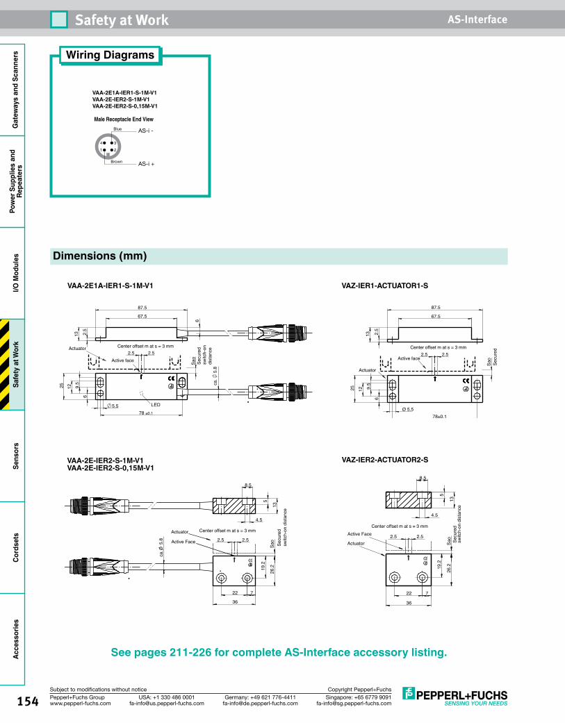
154 Singapore: +65 6779 [email protected]
USA: +1 330 486 [email protected]
Germany: +49 621 [email protected]
Pepperl+Fuchs Groupwww.pepperl-fuchs.com
Subject to modifications without notice Copyright Pepperl+Fuchs
Safety at Work AS-InterfaceG
atew
ays
and
Scan
ners
Pow
er S
uppl
ies
and
Repe
ater
sI/O
Mod
ules
Safe
ty a
t Wor
kSe
nsor
sCo
rdse
tsAc
cess
orie
s
Dimensions (mm)
Sao
Actuator
Active face
Center offset m at s = 3 mm
Sec
ured
switc
h-on
dist
ance
LED
2.5
13
67.5
87.5
9.5
25 12
6
78 ±0.1
5.5
2.52.5
ca.
5.8
6
VAA-2E1A-IER1-S-1M-V1
Actuator Center offset m at s = 3 mm
Sec
ured
switc
h-on
dis
tanc
e
Active Face
19.2
26.2
22
36
7
2.5 2.5
8.5
5
13
4.5
ca.
5.8
Sao
VAA-2E-IER2-S-1M-V1VAA-2E-IER2-S-0,15M-V1
Actuator
Center offset m at s = 3 mm
Secu
red
switc
h-on
dist
ance
Active Face
19.2
26.2
22
36
7
8.5
5
13
4.5
2.5 2.5
Sao
VAZ-IER2-ACTUATOR2-S
Sao
Actuator
Active face
Center offset m at s = 3 mm
Sec
ured
switc
h-on
dis
tanc
e
2.5
13
67.5
87.5
9.5
25 12
6
78±0.1
Ø 5.5
2.52.5
VAZ-IER1-ACTUATOR1-S
See pages 211-226 for complete AS-Interface accessory listing.
Wiring Diagrams
VAA-2E1A-IER1-S-1M-V1 VAA-2E-IER2-S-1M-V1 VAA-2E-IER2-S-0,15M-V1
1 2
4 3
Brown
Blue
AS-i +
AS-i -
Male Receptacle End View

155Singapore: +65 6779 [email protected]
USA: +1 330 486 [email protected]
Germany: +49 621 [email protected]
Pepperl+Fuchs Groupwww.pepperl-fuchs.com
Subject to modifications without notice Copyright Pepperl+Fuchs
Safety at Work AS-Interface
Gat
eway
s an
d Sc
anne
rsPo
wer
Sup
plie
s an
d Re
peat
ers
I/O M
odul
esSa
fety
at W
ork
Sens
ors
Cord
sets
Acce
ssor
ies
RFID Safety Interlock SwitchesSafety Solutions• Up to 4 safe read heads on one safety
module• No mechanical components to
wear out• Worry-free installation with no alignment
issues• Read heads and tags good for washdown
or dirty environments• Noncontact heads and tags great for
high-vibration environments
RFID Safety Interlock Switches OverviewRFID safety modules are unique because you can choose to connect as few as one read head, or as many as four read heads to one control module. A factory-programmed read-only code is embedded in every RFID tag. During the teach phase of the installation, the tag code is read and associated with a specific read head channel. If any one of the heads does not see the corresponding tag, the module will safely switch to the off state and inform the SafetyMonitors on the network.
RFID read heads and tags are typically used in harsh and dirty environments where other mechanical safety switches would not hold up. Because RFID technology is used, alignment issues are a thing of the
past and the RFID-based solution offers significant improvements in high-vibration environments. Other safety switches can get into states where one of its contacts are closed but the other is not. RFID readers can be off or on and no other intermediate or undetermined conditions are possible.
RFID readers cannot be bypassed or overridden by other noncontact guard switching technologies, making them the safest technology in the industry.
See pages 157-158 for RFID Safety Interlock Switches wiring and dimensions.
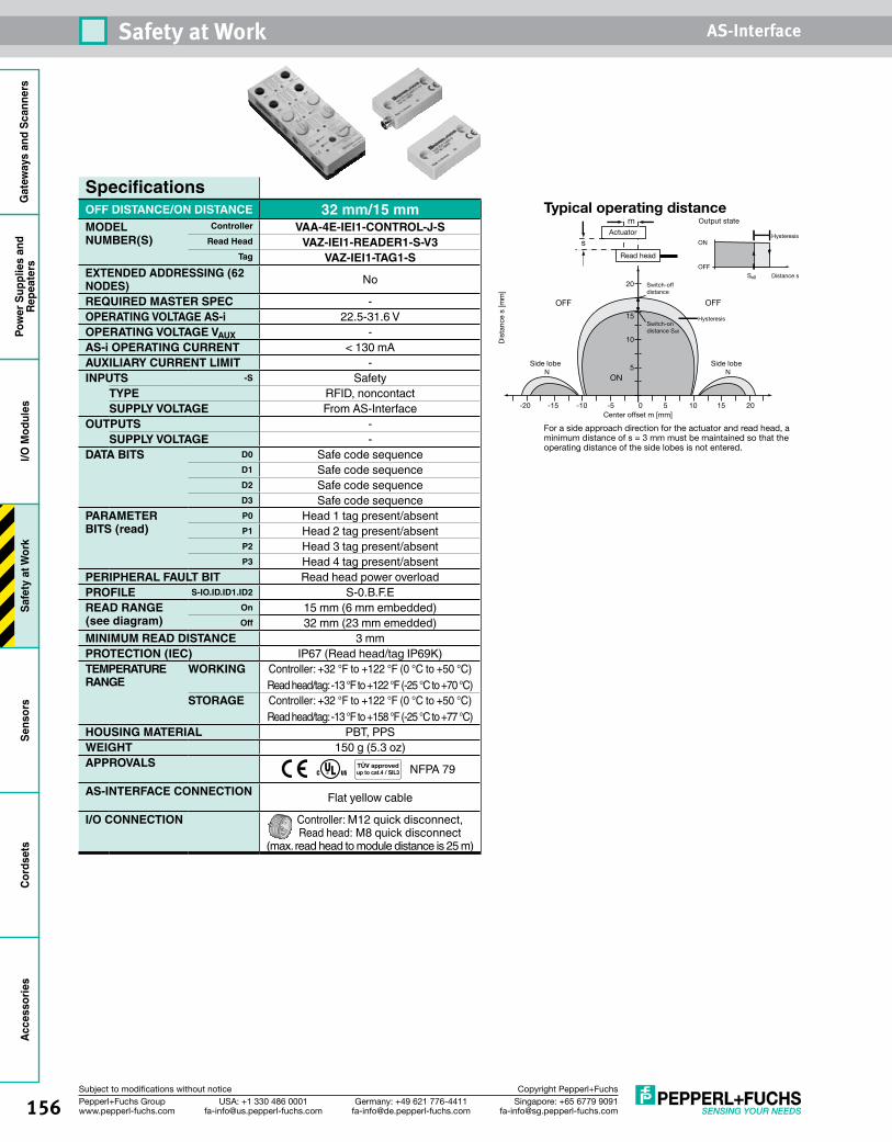
156 Singapore: +65 6779 [email protected]
USA: +1 330 486 [email protected]
Germany: +49 621 [email protected]
Pepperl+Fuchs Groupwww.pepperl-fuchs.com
Subject to modifications without notice Copyright Pepperl+Fuchs
Safety at Work AS-InterfaceG
atew
ays
and
Scan
ners
Pow
er S
uppl
ies
and
Repe
ater
sI/O
Mod
ules
Safe
ty a
t Wor
kSe
nsor
sCo
rdse
tsAc
cess
orie
s
SpecificationsOFF DISTANCE/ON DISTANCE 32 mm/15 mmMODEL NUMBER(S)
Controller VAA-4E-IEI1-CONTROL-J-SRead Head VAZ-IEI1-READER1-S-V3
Tag VAZ-IEI1-TAG1-SEXTENDED ADDRESSING (62 NODES) No
REQUIRED MASTER SPEC -OPERATING VOLTAGE AS-i 22.5-31.6 VOPERATING VOLTAGE VAUX -AS-i OPERATING CURRENT < 130 mAAUXILIARY CURRENT LIMIT -INPUTS -S Safety
TYPE RFID, noncontactSUPPLY VOLTAGE From AS-Interface
OUTPUTS -SUPPLY VOLTAGE -
DATA BITS D0 Safe code sequenceD1 Safe code sequenceD2 Safe code sequenceD3 Safe code sequence
PARAMETER BITS (read)
P0 Head 1 tag present/absentP1 Head 2 tag present/absentP2 Head 3 tag present/absentP3 Head 4 tag present/absent
PERIPHERAL FAULT BIT Read head power overloadPROFILE S-IO.ID.ID1.ID2 S-0.B.F.EREAD RANGE (see diagram)
On 15 mm (6 mm embedded)Off 32 mm (23 mm emedded)
MINIMUM READ DISTANCE 3 mmPROTECTION (IEC) IP67 (Read head/tag IP69K)TEMPERATURE RANGE
WORKING Controller: +32 °F to +122 °F (0 °C to +50 °C)Read head/tag: -13 °F to +122 °F (-25 °C to +70 °C)
STORAGE Controller: +32 °F to +122 °F (0 °C to +50 °C)Read head/tag: -13 °F to +158 °F (-25 °C to +77 °C)
HOUSING MATERIAL PBT, PPSWEIGHT 150 g (5.3 oz)APPROVALS NFPA 79
AS-INTERFACE CONNECTION Flat yellow cable
I/O CONNECTION Controller: M12 quick disconnect, Read head: M8 quick disconnect
(max. read head to module distance is 25 m)
-10-15 -5 0
Sa0
-20 5 201510
5
10
15
20
s
m
N N
Typical operating distance
For a side approach direction for the actuator and read head, aminimum distance of s = 3 mm must be maintained so that theoperating distance of the side lobes is not entered.
Center offset m [mm]
Output state
Side lobeSide lobe
Switch-offdistance
Switch-ondistance Sa0
Actuator
Read head
Hysteresis
OFF
ON
ON
OFF
OFF
Dis
tanc
e s
[mm
]
Hysteresis
Distance s
TÜV approvedup to cat.4 / SIL3
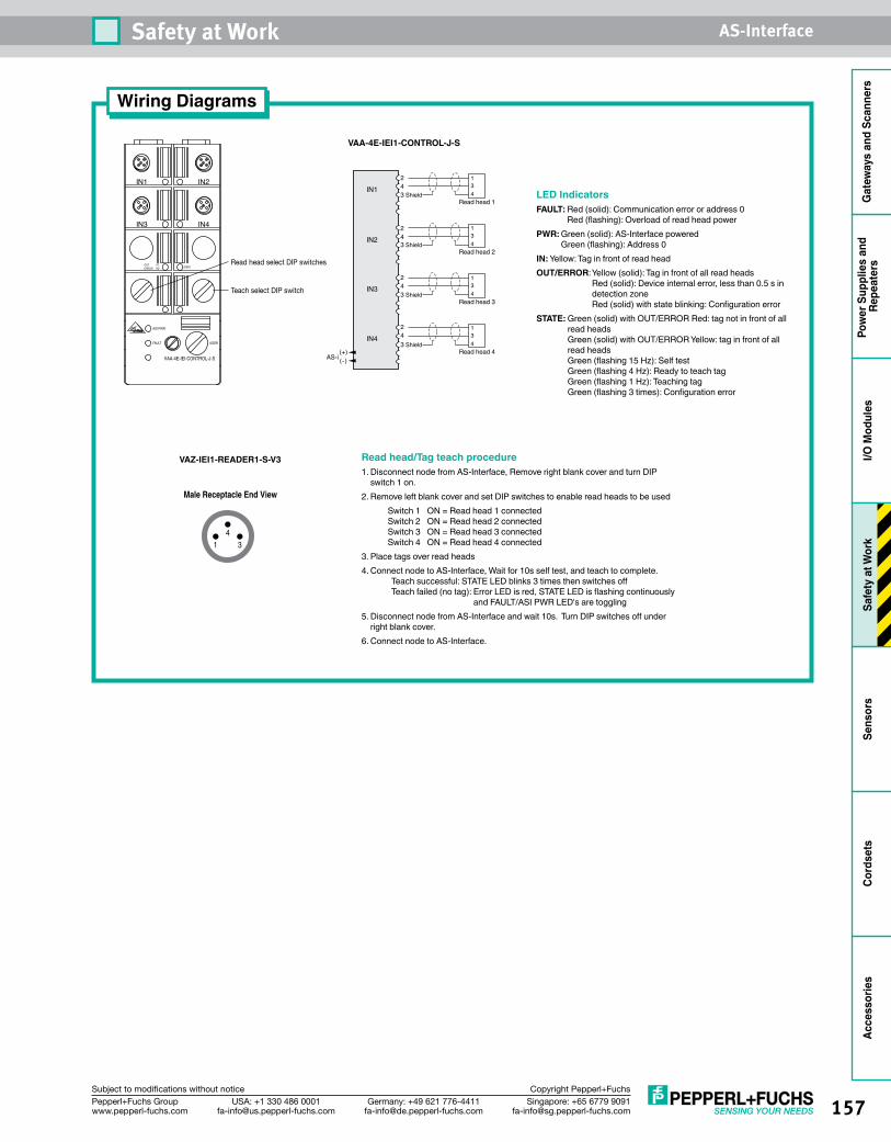
157Singapore: +65 6779 [email protected]
USA: +1 330 486 [email protected]
Germany: +49 621 [email protected]
Pepperl+Fuchs Groupwww.pepperl-fuchs.com
Subject to modifications without notice Copyright Pepperl+Fuchs
Safety at Work AS-Interface
Gat
eway
s an
d Sc
anne
rsPo
wer
Sup
plie
s an
d Re
peat
ers
I/O M
odul
esSa
fety
at W
ork
Sens
ors
Cord
sets
Acce
ssor
ies
IN1 IN2
ASI PWR
FAULT ADDR
IN3 IN4
OUTERROR
YERD STATE
VAA-4E-IEI-CONTROL-J-S
Teach select DIP switch
Read head select DIP switches
Wiring Diagrams
VAA-4E-IEI1-CONTROL-J-S
VAZ-IEI1-READER1-S-V3
Male Receptacle End View
14
3
LED IndicatorsFAULT: Red (solid): Communication error or address 0
Red (flashing): Overload of read head powerPWR: Green (solid): AS-Interface powered
Green (flashing): Address 0IN: Yellow: Tag in front of read headOUT/ERROR: Yellow (solid): Tag in front of all read heads
Red (solid): Device internal error, less than 0.5 s in detection zone Red (solid) with state blinking: Configuration error
STATE: Green (solid) with OUT/ERROR Red: tag not in front of all read heads Green (solid) with OUT/ERROR Yellow: tag in front of all read heads Green (flashing 15 Hz): Self test Green (flashing 4 Hz): Ready to teach tag Green (flashing 1 Hz): Teaching tag Green (flashing 3 times): Configuration error
2 134
43 Shield
24
24
24
Read head 1
IN1
IN2
IN3
IN4
(+)(-)AS-i
1343 Shield
Read head 2
1343 Shield
Read head 3
1343 Shield
Read head 4
Read head/Tag teach procedure1. Disconnect node from AS-Interface, Remove right blank cover and turn DIP
switch 1 on.2. Remove left blank cover and set DIP switches to enable read heads to be used
Switch 1 ON = Read head 1 connectedSwitch 2 ON = Read head 2 connectedSwitch 3 ON = Read head 3 connectedSwitch 4 ON = Read head 4 connected
3. Place tags over read heads4. Conn ect node to AS-Interface, Wait for 10s self test, and teach to complete.
Teach successful: STATE LED blinks 3 times then switches off Teach failed (no tag): Error LED is red, STATE LED is flashing continuously
and FAULT/ASI PWR LED's are toggling5. Disconnect node from AS-Interface and wait 10s. Turn DIP switches off under
right blank cover. 6. Connect node to AS-Interface.
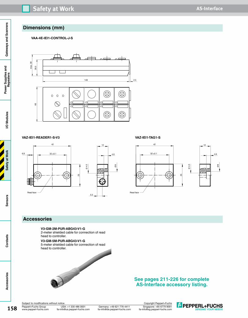
158 Singapore: +65 6779 [email protected]
USA: +1 330 486 [email protected]
Germany: +49 621 [email protected]
Pepperl+Fuchs Groupwww.pepperl-fuchs.com
Subject to modifications without notice Copyright Pepperl+Fuchs
Safety at Work AS-InterfaceG
atew
ays
and
Scan
ners
Pow
er S
uppl
ies
and
Repe
ater
sI/O
Mod
ules
Safe
ty a
t Wor
kSe
nsor
sCo
rdse
tsAc
cess
orie
s
28.5
max
. 39
60
149 2.5
5.5
6.8
Read face
8
4.5
4.6
12
25
32 ±0.1
42
Ø
Ø
8
4.5
4.6
12
25
32 ±0.1
42
Ø
Ø
Read face
Dimensions (mm)
VAA-4E-IEI1-CONTROL-J-S
VAZ-IEI1-READER1-S-V3 VAZ-IEI1-TAG1-S
Accessories
V3-GM-2M-PUR-ABG43-V1-G2-meter shielded cable for connection of read head to controller.V3-GM-5M-PUR-ABG43-V1-G5-meter shielded cable for connection of read head to controller.
See pages 211-226 for complete AS-Interface accessory listing.
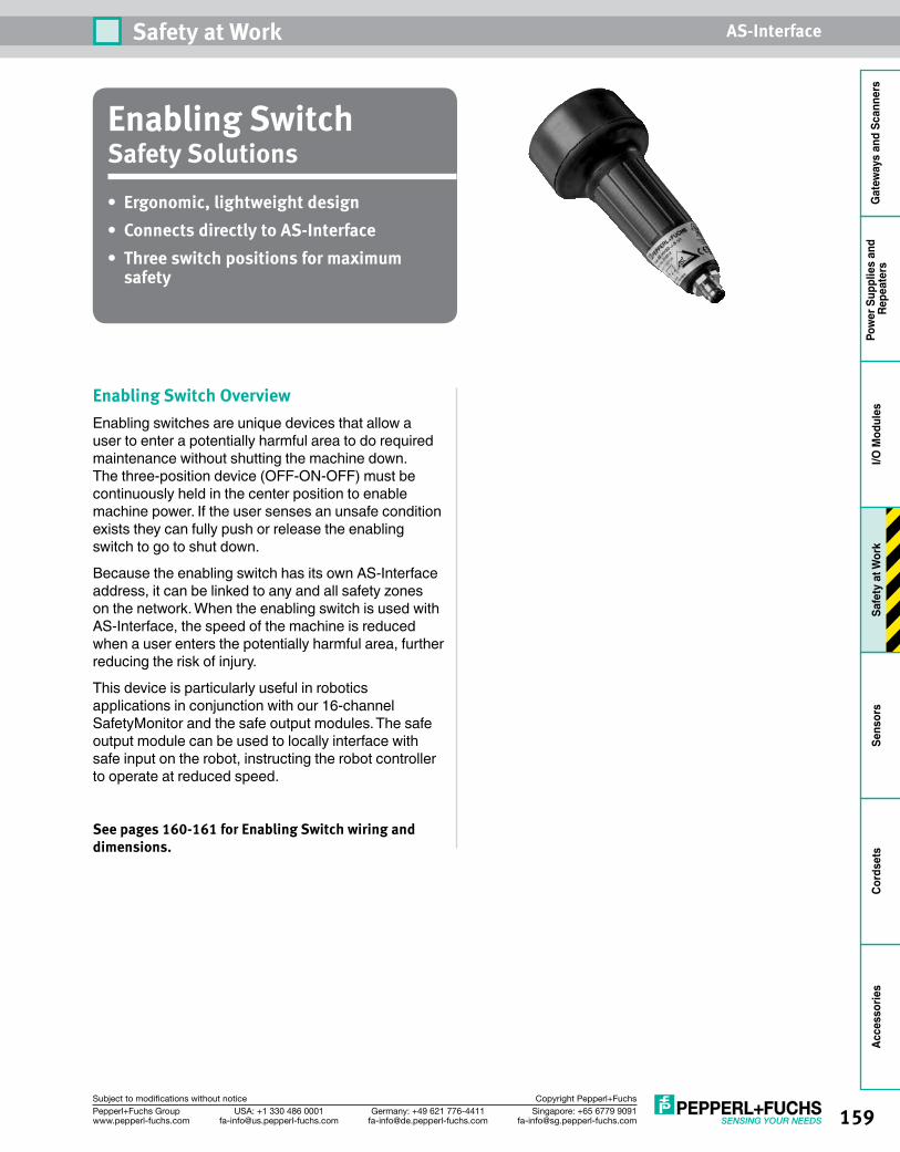
159Singapore: +65 6779 [email protected]
USA: +1 330 486 [email protected]
Germany: +49 621 [email protected]
Pepperl+Fuchs Groupwww.pepperl-fuchs.com
Subject to modifications without notice Copyright Pepperl+Fuchs
Safety at Work AS-Interface
Gat
eway
s an
d Sc
anne
rsPo
wer
Sup
plie
s an
d Re
peat
ers
I/O M
odul
esSa
fety
at W
ork
Sens
ors
Cord
sets
Acce
ssor
ies
Enabling SwitchSafety Solutions• Ergonomic, lightweight design• Connects directly to AS-Interface• Three switch positions for maximum
safety
Enabling Switch OverviewEnabling switches are unique devices that allow a user to enter a potentially harmful area to do required maintenance without shutting the machine down. The three-position device (OFF-ON-OFF) must be continuously held in the center position to enable machine power. If the user senses an unsafe condition exists they can fully push or release the enabling switch to go to shut down.
Because the enabling switch has its own AS-Interface address, it can be linked to any and all safety zones on the network. When the enabling switch is used with AS-Interface, the speed of the machine is reduced when a user enters the potentially harmful area, further reducing the risk of injury.
This device is particularly useful in robotics applications in conjunction with our 16-channel SafetyMonitor and the safe output modules. The safe output module can be used to locally interface with safe input on the robot, instructing the robot controller to operate at reduced speed.
See pages 160-161 for Enabling Switch wiring and dimensions.
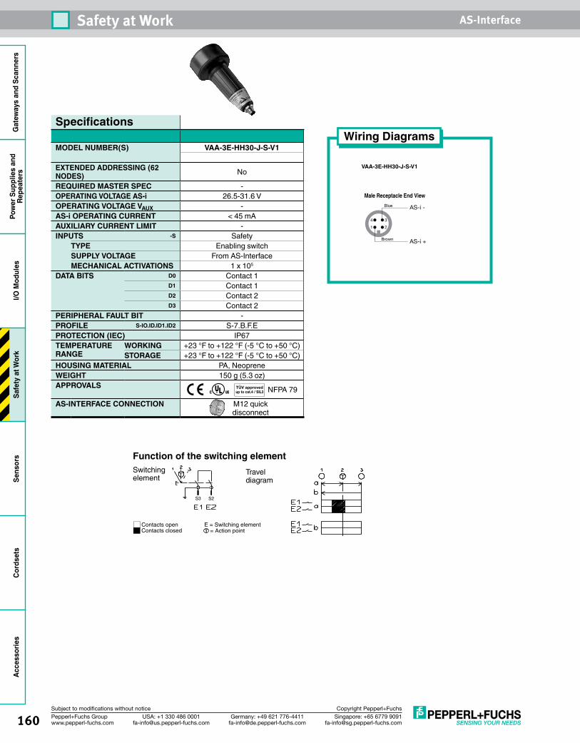
160 Singapore: +65 6779 [email protected]
USA: +1 330 486 [email protected]
Germany: +49 621 [email protected]
Pepperl+Fuchs Groupwww.pepperl-fuchs.com
Subject to modifications without notice Copyright Pepperl+Fuchs
Safety at Work AS-InterfaceG
atew
ays
and
Scan
ners
Pow
er S
uppl
ies
and
Repe
ater
sI/O
Mod
ules
Safe
ty a
t Wor
kSe
nsor
sCo
rdse
tsAc
cess
orie
s
Specifications
MODEL NUMBER(S) VAA-3E-HH30-J-S-V1
EXTENDED ADDRESSING (62 NODES) No
REQUIRED MASTER SPEC -OPERATING VOLTAGE AS-i 26.5-31.6 VOPERATING VOLTAGE VAUX -AS-i OPERATING CURRENT < 45 mAAUXILIARY CURRENT LIMIT -INPUTS -S Safety
TYPE Enabling switchSUPPLY VOLTAGE From AS-InterfaceMECHANICAL ACTIVATIONS 1 x 10⁵
DATA BITS D0 Contact 1D1 Contact 1D2 Contact 2D3 Contact 2
PERIPHERAL FAULT BIT -PROFILE S-IO.ID.ID1.ID2 S-7.B.F.EPROTECTION (IEC) IP67TEMPERATURE RANGE
WORKING +23 °F to +122 °F (-5 °C to +50 °C)STORAGE +23 °F to +122 °F (-5 °C to +50 °C)
HOUSING MATERIAL PA, NeopreneWEIGHT 150 g (5.3 oz)APPROVALS NFPA 79
AS-INTERFACE CONNECTION M12 quick disconnect
Wiring Diagrams
VAA-3E-HH30-J-S-V1
1 2
4 3
Brown
Blue
AS-i +
AS-i -
Male Receptacle End View
Switchingelement
Traveldiagram
Contacts openContacts closed = Action point
E = Switching element
Function of the switching element
S3 S2
T
TÜV approvedup to cat.4 / SIL3
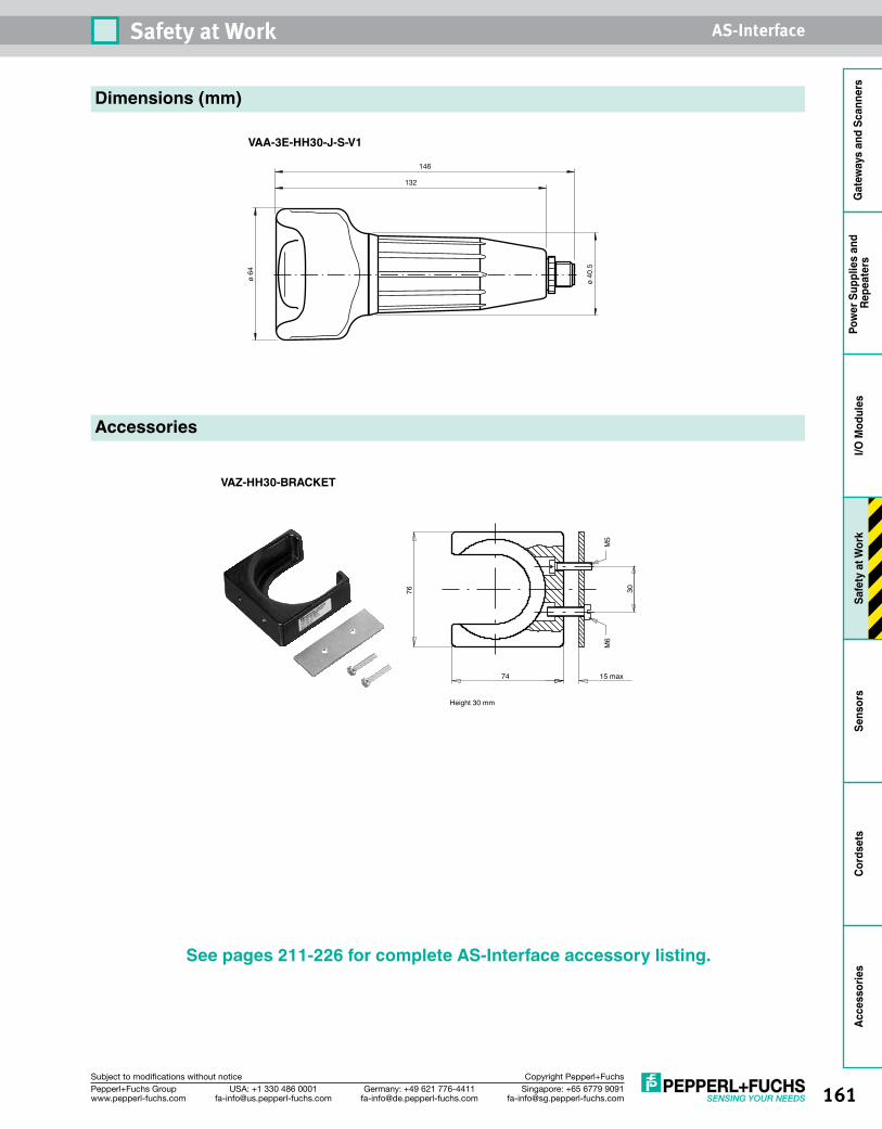
161Singapore: +65 6779 [email protected]
USA: +1 330 486 [email protected]
Germany: +49 621 [email protected]
Pepperl+Fuchs Groupwww.pepperl-fuchs.com
Subject to modifications without notice Copyright Pepperl+Fuchs
Safety at Work AS-Interface
Gat
eway
s an
d Sc
anne
rsPo
wer
Sup
plie
s an
d Re
peat
ers
I/O M
odul
esSa
fety
at W
ork
Sens
ors
Cord
sets
Acce
ssor
ies
132
146
ø 64
ø 40
.5
Height 30 mm
76
74 15 max
M6
M5
30
Dimensions (mm)
VAA-3E-HH30-J-S-V1
Accessories
VAZ-HH30-BRACKET
See pages 211-226 for complete AS-Interface accessory listing.
162 Singapore: +65 6779 [email protected]
USA: +1 330 486 [email protected]
Germany: +49 621 [email protected]
Pepperl+Fuchs Groupwww.pepperl-fuchs.com
Subject to modifications without notice Copyright Pepperl+Fuchs
Safety at Work AS-InterfaceG
atew
ays
and
Scan
ners
Pow
er S
uppl
ies
and
Repe
ater
sI/O
Mod
ules
Safe
ty a
t Wor
kSe
nsor
sCo
rdse
tsAc
cess
orie
s
Notes

Gat
eway
s an
d Sc
anne
rsPo
wer
Sup
plie
s an
d Re
peat
ers
I/O M
odul
esSa
fety
at W
ork
Sens
ors
Cord
sets
Acce
ssor
ies
163Singapore: +65 6779 [email protected]
USA: +1 330 486 [email protected]
Germany: +49 621 [email protected]
Pepperl+Fuchs Groupwww.pepperl-fuchs.com
Subject to modifications without notice Copyright Pepperl+Fuchs
IntelligentSensors
Intelligent Inductive SensorsSensors can be equipped with the AS-Interface chip. Every sensor can be a module on AS-Interface and up to 62 smart sensors can be on the network at one time. Each sensor provides valuable diagnostic information. “Intelligent” sensors are self-monitoring, programmable, and transmit data over the network to a controller. An AS-Interface sensor offers many features that are not available with a standard sensor, such as coil monitoring, precollision, and out of range detection; and all are NO/NC programmable. Additional diagnostic capabilities available with intelligent inductive sensors include the following:
Normally Open/Normally Closed ProgrammableStocking two sensors is no longer required. With AS-Interface intelligent sensors, OEMs have the opportunity to reduce the number of sensors on a system. Instead of stocking inductive sensors with normally open and normally closed outputs, one intelligent sensor can be used and configured to be normally open or normally closed. Each time the sensor is plugged in, it is automatically configured to the correct setting.
Prefailure IndicationPrefailure indication is another advanced function offered in some of the Pepperl+Fuchs AS-Interface intelligent inductive sensors. If the target is between 100% and 120% of the sensor’s nominal sensing range, the prefailure bit is reported. When this situation is indicated, users can correct the mounting and/or the misalignment before the target is out of range.
Precollision IndicationWhen a target gets too close to an inductive sensor face, a precollision condition is indicated. Users can reposition the sensor so that the target does not hit the sensor. This type of indication can reduce the cost of replacing a standard sensor that was damaged because of misalignment.
Oscillator MonitoringRepeated direct contact between sensors and their targets can cause coils and oscillators to stop running. If a sensor without oscillator monitoring stops operating, the PLC receives a failure code only after the target is missed. Using AS-Interface and intelligent sensors, a failure notice is immediately sent to the scanner/gateway in a data bit. The PLC is then notified, and the damaged sensor can be replaced quickly and easily, improving quality and reducing downtime.
Activation Delay FilterWith activation filtering, all targets present for less than 15 ms will not be transferred to AS-Interface. This eliminates false triggering due to noise, weld fields, and other unforeseen disruptions. When the sensor is programmed for normally open, there is a 15 ms ON delay. When the sensor is programmed for normally closed, there is a 15 ms OFF delay.
There are many housing styles available. All are directly connected to the AS-Interface line, and power and communications run over the same two wires. Pepperl+Fuchs has 12 mm, 18 mm, and 30 mm
Cylindrical Inductive.................................... 165Limit Switch Inductive ................................. 169Rhino™ Inductive ....................................... 172Rectangular Inductive ................................. 174Valve Positioning Inductive ......................... 176Series 28 Photoelectric ............................... 179BVS58/BVM58 Series Solid-Shaft Absolute Rotary Encoders ............................ 188BSS58/BSM58 Series Hollow-Shaft Absolute Rotary Encoders ............................ 192
164 Singapore: +65 6779 [email protected]
USA: +1 330 486 [email protected]
Germany: +49 621 [email protected]
Pepperl+Fuchs Groupwww.pepperl-fuchs.com
Subject to modifications without notice Copyright Pepperl+Fuchs
Gat
eway
s an
d Sc
anne
rsPo
wer
Sup
plie
s an
dRe
peat
ers
I/O M
odul
esSa
fety
at W
ork
Sens
ors
Cord
sets
Acce
ssor
ies
cylindrical, limit switch style, rectangular, Rhino, and flat packs for your AS-Interface network.
Intelligent Photoelectric SensorsIn most applications, I/O modules bring sensor inputs back to the AS-Interface scanner/gateway and to the PLC. Modules can have up to 4 inputs (plus additional outputs), and each module takes up a full or a half address. Like modules, intelligent photoelectric sensors also take up a half address. Up to 4 input bits are available to provide valuable diagnostic information.
Additional Diagnostic Capabilities Available With Intelligent Photoelectric Sensors
• Weak signal indication: When photoelectric sensors are used, it is possible to detect a weak signal before the sensor stops working. Maintenance can be performed on an as-needed basis.
• Configurable light ON/dark ON: One intelligent sensor can be used and configured for the light ON/dark ON behavior. Separate sensors are not necessary.
Absolute Rotary EncodersIn automation applications, rotary encoders are used as sensors for angle, position, speed, and acceleration. By using spindles, gear racks, measuring wheels, or cable pulls, linear movements can also be monitored by a rotary encoder. Rotary encoders convert a mechanical rotation value into an electrical signal that can be processed by counters, tachometers, logic controllers, and industrial PCs. Rotary encoders are among the most useful and versatile pieces of equipment available to the automation industry.
Pepperl+Fuchs is proud to offer the industry’s only AS-Interface absolute rotary encoders. Absolute encoders provide a uniquely coded numerical value for each shaft position. They eliminate the need for expensive input components in a positioning
application because they have built-in reference data.
Pepperl+Fuchs AS-Interface rotary encoders use state-of-the-art components and the latest technologies to ensure reliability and a long service life. Additionally, Pepperl+Fuchs encoders feature precision bearings for a long life and low maintenance, with wire connections that are sealed up to IP65. Durable aluminum housings and solid-state circuitry make Pepperl+Fuchs encoders suitable for rugged environments.
Our absolute rotary encoders allow an easy 2-wire connection to AS-Interface and are available in both single- and multi-turn versions. Single-turn absolute encoders divide the shaft into a defined number of steps. The maximum resolution is 13 bits, which means that up to 8192 positions can be defined. By using a multi-step gear, multi-turn absolute encoders not only provide the angular position within a revolution, but also the number of revolutions. Multi-turn encoders have a 16-bit resolution or 65,536 total measuring steps.
Four nodes are used to transmit the 16 bits of data back to the AS-Interface network, and there is an AS-Interface network gateway/scanner available for almost any system. The standard 58 mm housings are available in solid-shaft (BV series) or recessed hollow-shaft (BS series) versions and in a variety of mounting configurations.
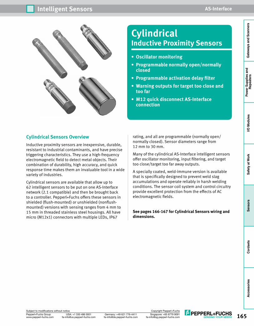
165Singapore: +65 6779 [email protected]
USA: +1 330 486 [email protected]
Germany: +49 621 [email protected]
Pepperl+Fuchs Groupwww.pepperl-fuchs.com
Subject to modifications without notice Copyright Pepperl+Fuchs
Intelligent Sensors AS-Interface
Gat
eway
s an
d Sc
anne
rsPo
wer
Sup
plie
s an
d Re
peat
ers
I/O M
odul
esSa
fety
at W
ork
Sens
ors
Cord
sets
Acce
ssor
ies
CylindricalInductive Proximity Sensors• Oscillatormonitoring• Programmablenormallyopen/normally
closed• Programmableactivationdelayfilter• Warningoutputsfortargettoocloseand
too far• M12quickdisconnectAS-Interface
connection
Cylindrical Sensors OverviewInductive proximity sensors are inexpensive, durable, resistant to industrial contaminants, and have precise triggering characteristics. They use a high-frequency electromagnetic field to detect metal objects. Their combination of durability, high accuracy, and quick response time makes them an invaluable tool in a wide variety of industries.
Cylindrical sensors are available that allow up to 62 intelligent sensors to be put on one AS-Interface network (2.1 compatible) and then be brought back to a controller. Pepperl+Fuchs offers these sensors in shielded (flush-mounted) or unshielded (nonflush-mounted) versions with sensing ranges from 4 mm to 15 mm in threaded stainless steel housings. All have micro (M12x1) connectors with multiple LEDs, IP67
rating, and all are programmable (normally open/normally closed). Sensor diameters range from 12 mm to 30 mm.
Many of the cylindrical AS-Interface intelligent sensors offer oscillator monitoring, input filtering, and target too close/target too far away outputs.
A specially coated, weld-immune version is available that is specifically designed to prevent weld slag accumulations and operate reliably in harsh welding conditions. The sensor coil system and control circuitry provide excellent protection from the effects of AC electromagnetic fields.
See pages 166-167 for Cylindrical Sensors wiring and dimensions.
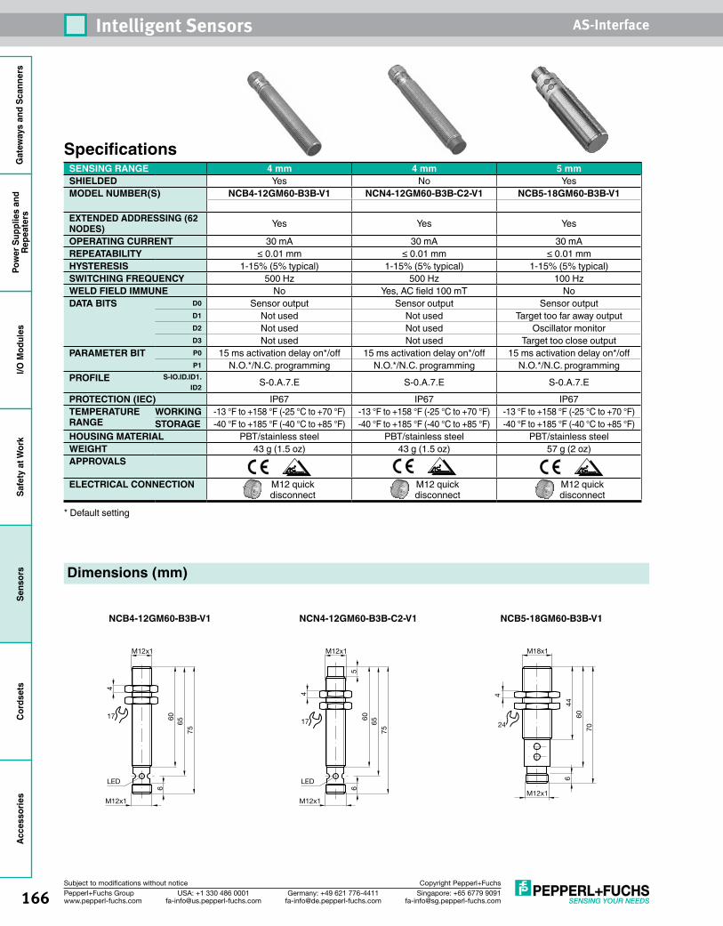
166 Singapore: +65 6779 [email protected]
USA: +1 330 486 [email protected]
Germany: +49 621 [email protected]
Pepperl+Fuchs Groupwww.pepperl-fuchs.com
Subject to modifications without notice Copyright Pepperl+Fuchs
Intelligent Sensors AS-InterfaceG
atew
ays
and
Scan
ners
Pow
er S
uppl
ies
and
Repe
ater
sI/O
Mod
ules
Safe
ty a
t Wor
kSe
nsor
sCo
rdse
tsAc
cess
orie
s
SpecificationsSENSING RANGE 4 mm 4 mm 5 mmSHIELDED Yes No YesMODEL NUMBER(S) NCB4-12GM60-B3B-V1 NCN4-12GM60-B3B-C2-V1 NCB5-18GM60-B3B-V1
EXTENDED ADDRESSING (62 NODES) Yes Yes Yes
OPERATING CURRENT 30 mA 30 mA 30 mAREPEATABILITY ≤ 0.01 mm ≤ 0.01 mm ≤ 0.01 mmHYSTERESIS 1-15% (5% typical) 1-15% (5% typical) 1-15% (5% typical)SWITCHING FREQUENCY 500 Hz 500 Hz 100 HzWELD FIELD IMMUNE No Yes, AC field 100 mT NoDATA BITS D0 Sensor output Sensor output Sensor output
D1 Not used Not used Target too far away outputD2 Not used Not used Oscillator monitorD3 Not used Not used Target too close output
PARAMETER BIT P0 15 ms activation delay on*/off 15 ms activation delay on*/off 15 ms activation delay on*/offP1 N.O.*/N.C. programming N.O.*/N.C. programming N.O.*/N.C. programming
PROFILE S-IO.ID.ID1.ID2 S-0.A.7.E S-0.A.7.E S-0.A.7.E
PROTECTION (IEC) IP67 IP67 IP67TEMPERATURE RANGE
WORKING -13 °F to +158 °F (-25 °C to +70 °F) -13 °F to +158 °F (-25 °C to +70 °F) -13 °F to +158 °F (-25 °C to +70 °F)STORAGE -40 °F to +185 °F (-40 °C to +85 °F) -40 °F to +185 °F (-40 °C to +85 °F) -40 °F to +185 °F (-40 °C to +85 °F)
HOUSING MATERIAL PBT/stainless steel PBT/stainless steel PBT/stainless steelWEIGHT 43 g (1.5 oz) 43 g (1.5 oz) 57 g (2 oz)APPROVALS
ELECTRICAL CONNECTION M12 quick disconnect
M12 quick disconnect
M12 quick disconnect
* Default setting
Dimensions (mm)
NCB4-12GM60-B3B-V1
M12x1
4
6065
75
M12x1
LED
6
17
NCN4-12GM60-B3B-C2-V1
M12x1
4
6065
75
M12x1
LED
65
17
NCB5-18GM60-B3B-V1
70
M18x1
4
44
M12x1
60
24
6
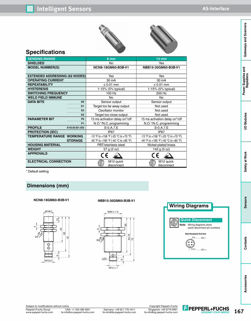
167Singapore: +65 6779 [email protected]
USA: +1 330 486 [email protected]
Germany: +49 621 [email protected]
Pepperl+Fuchs Groupwww.pepperl-fuchs.com
Subject to modifications without notice Copyright Pepperl+Fuchs
Intelligent Sensors AS-Interface
Gat
eway
s an
d Sc
anne
rsPo
wer
Sup
plie
s an
d Re
peat
ers
I/O M
odul
esSa
fety
at W
ork
Sens
ors
Cord
sets
Acce
ssor
ies
Dimensions (mm)
NCN8-18GM60-B3B-V1 NBB15-30GM60-B3B-V1
70
M18x1
4
44
M12x1
60
24
610
LED
5
M12 x 1
6
6064
.75
75
M30 x 1.5
36
Quick DisconnectNote: Wiring diagrams show quick disconnect pin numbers
Wiring Diagrams
1 2
4 3
Brown
Blue
AS-i +
AS-i -
Male Receptacle End View
SpecificationsSENSING RANGE 8 mm 15 mmSHIELDED No YesMODEL NUMBER(S) NCN8-18GM60-B3B-V1 NBB15-30GM60-B3B-V1
EXTENDED ADDRESSING (62 NODES) Yes YesOPERATING CURRENT 30 mA 30 mAREPEATABILITY ≤ 0.01 mm ≤ 0.01 mmHYSTERESIS 1-15% (5% typical) 1-15% (5% typical)SWITCHING FREQUENCY 100 Hz 200 HzWELD FIELD IMMUNE No NoDATA BITS D0 Sensor output Sensor output
D1 Target too far away output Not usedD2 Oscillator monitor Not usedD3 Target too close output Not used
PARAMETER BIT P0 15 ms activation delay on*/off 15 ms activation delay on*/offP1 N.O.*/N.C. programming N.O.*/N.C. programming
PROFILE S-IO.ID.ID1.ID2 S-0.A.7.E S-0.A.7.EPROTECTION (IEC) IP67 IP67TEMPERATURE RANGE WORKING -13 °F to +158 °F (-25 °C to +70 °F) -13 °F to +158 °F (-25 °C to +70 °F)
STORAGE -40 °F to +185 °F (-40 °C to +85 °F) -40 °F to +185 °F (-40 °C to +85 °F)HOUSING MATERIAL PBT/stainless steel Nickel-plated brassWEIGHT 57 g (2 oz) 142 g (5 oz)APPROVALS
ELECTRICAL CONNECTION M12 quick disconnect
M12 quick disconnect
* Default setting
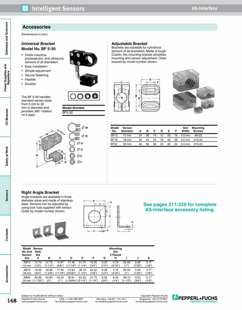
168 Singapore: +65 6779 [email protected]
USA: +1 330 486 [email protected]
Germany: +49 621 [email protected]
Pepperl+Fuchs Groupwww.pepperl-fuchs.com
Subject to modifications without notice Copyright Pepperl+Fuchs
Intelligent Sensors AS-InterfaceG
atew
ays
and
Scan
ners
Pow
er S
uppl
ies
and
Repe
ater
sI/O
Mod
ules
Safe
ty a
t Wor
kSe
nsor
sCo
rdse
tsAc
cess
orie
s
Accessories(Dimensions in mm)
Model Sensor Slot Mounting No. Diameter A B C D E F Width Screws BF12 12 mm 24 36 19 12 30 16 4.5 mm #8-32 BF18 18 mm 30 44 24 18 40 26 5.5 mm #10-24 BF30 30 mm 40 56 36 30 40 24 5.5 mm #10-24
Model Number BF5-30
D
FC
BA
E
Right Angle Bracket Angle brackets are available in three diameter sizes and made of stainless steel. Sensors can be adjusted by using lock nuts supplied with sensor. Order by model number shown.
A
HG
BC
D
E
F
K
JI
54
25
67
12
1525
25
30
18
14
12
8
5
Universal Bracket Model No. BF 5-30• Holds inductive,
photoelectric, and ultrasonic sensors of all diameters
• Easy installation• Simple adjustment• Secure fastening• Flexible• Durable
The BF 5-30 handles standard sensor sizes from 5 mm to 30 mm in diameter and provides 360° rotation on 2 axes.
Adjustable Bracket Brackets are available for cylindrical sensors of all diameters. Made of tough Crastin, the mounting bracket simplifies mounting and sensor adjustment. Order bracket by model number shown.
Model Sensor Mounting No. and Hole Dia Sensor Dia 2 Places Dia A B C D E F G H I J K AB12 12.70 31.75 15.87 17.46 31.75 19.05 6.35 4.76 25.40 5.56 3.17 12 mm (1/2") (1-1/4") (5/8") (11/16") (1-1/4") (3/4") (1/4") (3/16") (1") (7/32") (1/8") AB18 19.05 34.92 17.46 19.84 38.10 22.22 6.35 4.76 25.40 5.56 3.17 18 mm (3/4") (1-3/8") (11/16") (25/32") (1-1/2") (7/8") (1/4") (3/16") (1") (7/32") (1/8") AB30 30.96 50.80 25.40 36.91 63.50 31.75 9.52 6.35 38.10 9.52 3.17 30 mm (1-7/32") (2") (1") (1-29/64") (2-1/2") (1-1/4") (3/8") (1/4") (1-1/2") (3/8") (1/8")
See pages 211-226 for complete AS-Interface accessory listing.
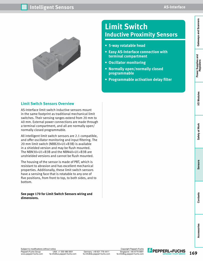
169Singapore: +65 6779 [email protected]
USA: +1 330 486 [email protected]
Germany: +49 621 [email protected]
Pepperl+Fuchs Groupwww.pepperl-fuchs.com
Subject to modifications without notice Copyright Pepperl+Fuchs
Intelligent Sensors AS-Interface
Gat
eway
s an
d Sc
anne
rsPo
wer
Sup
plie
s an
d Re
peat
ers
I/O M
odul
esSa
fety
at W
ork
Sens
ors
Cord
sets
Acce
ssor
ies
Limit SwitchInductive Proximity Sensors• 5-wayrotatablehead• EasyAS-Interfaceconnectionwith
terminal compartment• Oscillatormonitoring• Normallyopen/normallyclosed
programmable• Programmableactivationdelayfilter
Limit Switch Sensors OverviewAS-Interface limit switch inductive sensors mount in the same footprint as traditional mechanical limit switches. Their sensing ranges extend from 20 mm to 40 mm. External power connections are made through a terminal compartment, and all are normally open/normally closed programmable.
All intelligent limit switch sensors are 2.1 compatible, and offer oscillator monitoring and input filtering. The 20 mm limit switch (NBB20+U1+B3B) is available in a shielded version and may be flush mounted. The NBN30+U1+B3B and the NBN40+U1+B3B are unshielded versions and cannot be flush mounted.
The housing of the sensor is made of PBT, which is resistant to abrasion and has excellent mechanical properties. Additionally, these limit switch sensors have a sensing face that is rotatable to any one of five positions, from front to top, to both sides, and to bottom.
See page 170 for Limit Switch Sensors wiring and dimensions.
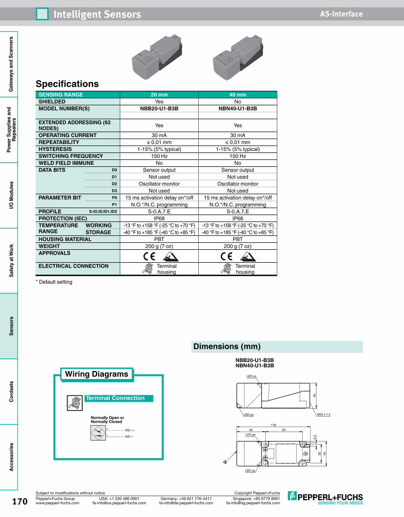
170 Singapore: +65 6779 [email protected]
USA: +1 330 486 [email protected]
Germany: +49 621 [email protected]
Pepperl+Fuchs Groupwww.pepperl-fuchs.com
Subject to modifications without notice Copyright Pepperl+Fuchs
Intelligent Sensors AS-InterfaceG
atew
ays
and
Scan
ners
Pow
er S
uppl
ies
and
Repe
ater
sI/O
Mod
ules
Safe
ty a
t Wor
kSe
nsor
sCo
rdse
tsAc
cess
orie
s
SpecificationsSENSING RANGE 20 mm 40 mmSHIELDED Yes NoMODEL NUMBER(S) NBB20-U1-B3B NBN40-U1-B3B
EXTENDED ADDRESSING (62 NODES) Yes Yes
OPERATING CURRENT 30 mA 30 mAREPEATABILITY ≤ 0.01 mm ≤ 0.01 mmHYSTERESIS 1-15% (5% typical) 1-15% (5% typical)SWITCHING FREQUENCY 150 Hz 150 HzWELD FIELD IMMUNE No NoDATA BITS D0 Sensor output Sensor output
D1 Not used Not usedD2 Oscillator monitor Oscillator monitorD3 Not used Not used
PARAMETER BIT P0 15 ms activation delay on*/off 15 ms activation delay on*/offP1 N.O.*/N.C. programming N.O.*/N.C. programming
PROFILE S-IO.ID.ID1.ID2 S-0.A.7.E S-0.A.7.EPROTECTION (IEC) IP68 IP68TEMPERATURE RANGE
WORKING -13 °F to +158 °F (-25 °C to +70 °F) -13 °F to +158 °F (-25 °C to +70 °F)STORAGE -40 °F to +185 °F (-40 °C to +85 °F) -40 °F to +185 °F (-40 °C to +85 °F)
HOUSING MATERIAL PBT PBTWEIGHT 200 g (7 oz) 200 g (7 oz)APPROVALS
ELECTRICAL CONNECTION Terminal housing
Terminal housing
* Default setting
Wiring Diagrams
Terminal Connection
AS-i +
AS-i -
3
4
Normally Open orNormally Closed
6046118
30 40
40
LED ye
LED ye
LED gn
LED gn
5.3
M20 x 1.5
Dimensions (mm)NBB20-U1-B3BNBN40-U1-B3B
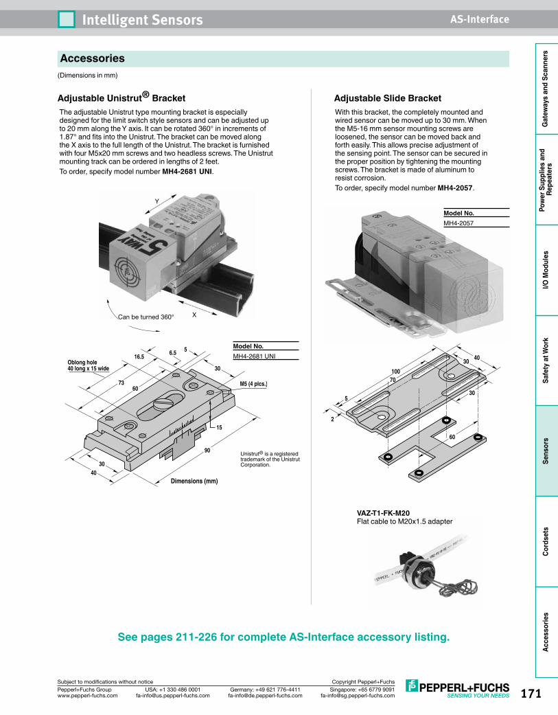
171Singapore: +65 6779 [email protected]
USA: +1 330 486 [email protected]
Germany: +49 621 [email protected]
Pepperl+Fuchs Groupwww.pepperl-fuchs.com
Subject to modifications without notice Copyright Pepperl+Fuchs
Intelligent Sensors AS-Interface
Gat
eway
s an
d Sc
anne
rsPo
wer
Sup
plie
s an
d Re
peat
ers
I/O M
odul
esSa
fety
at W
ork
Sens
ors
Cord
sets
Acce
ssor
ies
Accessories(Dimensions in mm)
60
70100
4030
30
2
5
Y
XCan be turned 360°
30
7360
16.56.5
M5 (4 plcs.)
15
40
90
Oblong hole40 long x 15 wide
5
30
Dimensions (mm)
Unistrut® is a registered trademark of the Unistrut Corporation.
VAZ-T1-FK-M20Flat cable to M20x1.5 adapter
With this bracket, the completely mounted and wired sensor can be moved up to 30 mm. When the M5-16 mm sensor mounting screws are loosened, the sensor can be moved back and forth easily. This allows precise adjustment of the sensing point. The sensor can be secured in the proper position by tightening the mounting screws. The bracket is made of aluminum to resist corrosion.To order, specify model number MH4-2057.
Adjustable Slide BracketAdjustable Unistrut® BracketThe adjustable Unistrut type mounting bracket is especially designed for the limit switch style sensors and can be adjusted up to 20 mm along the Y axis. It can be rotated 360° in increments of 1.87° and fits into the Unistrut. The bracket can be moved along the X axis to the full length of the Unistrut. The bracket is furnished with four M5x20 mm screws and two headless screws. The Unistrut mounting track can be ordered in lengths of 2 feet.To order, specify model number MH4-2681 UNI.
Model No. MH4-2057
Model No. MH4-2681 UNI
See pages 211-226 for complete AS-Interface accessory listing.

172 Singapore: +65 6779 [email protected]
USA: +1 330 486 [email protected]
Germany: +49 621 [email protected]
Pepperl+Fuchs Groupwww.pepperl-fuchs.com
Subject to modifications without notice Copyright Pepperl+Fuchs
Intelligent Sensors AS-InterfaceG
atew
ays
and
Scan
ners
Pow
er S
uppl
ies
and
Repe
ater
sI/O
Mod
ules
Safe
ty a
t Wor
kSe
nsor
sCo
rdse
tsAc
cess
orie
s
Rhino™Inductive Proximity Sensors• 25-positionrotatinghead• Oscillatormonitoring• Normallyopen/normallyclosed
programmable• Programmableactivationdelayfilter• M12quickdisconnectAS-Interface
connection
Rhino Sensors OverviewThe popular Rhino series uses a durable, die-cast metal mounting bracket. Rhinos feature a “Quick-Pivot” sensing head, allowing tool-free configuration of the sensing face to any position. Rhino models offer sensing ranges and mounting footprints identical to inductive limit switches, but require only 1/3 the mounting space.
All of our intelligent Rhino sensors are 2.1 compatible, and offer oscillator monitoring, input filtering, and are normally open/normally closed programmable. The Rhino has a sensing range up to 30 mm. The 20 mm Rhino (NBB20-L2-B3B-V1) is available in a shielded version and may be flush mounted. The NBN30-L2-B3B-V1 and the NBN40-L2-B3B-V1 are unshielded versions and cannot be flush mounted.
See page 173 for Rhino Sensors wiring and dimensions.
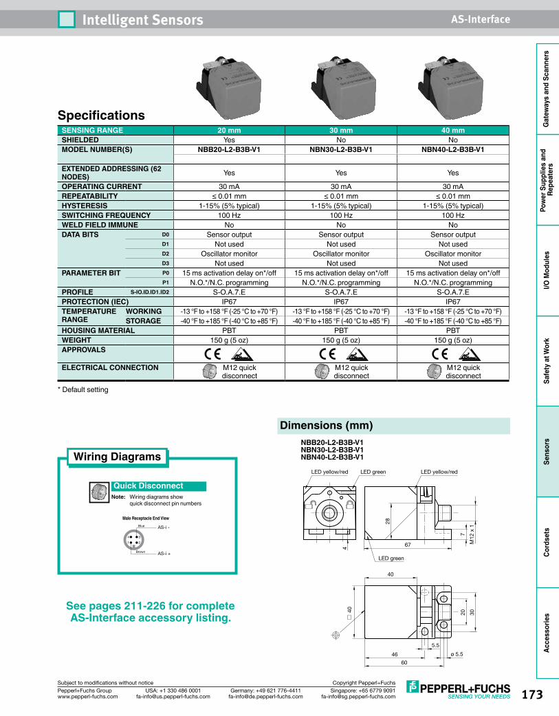
173Singapore: +65 6779 [email protected]
USA: +1 330 486 [email protected]
Germany: +49 621 [email protected]
Pepperl+Fuchs Groupwww.pepperl-fuchs.com
Subject to modifications without notice Copyright Pepperl+Fuchs
Intelligent Sensors AS-Interface
Gat
eway
s an
d Sc
anne
rsPo
wer
Sup
plie
s an
d Re
peat
ers
I/O M
odul
esSa
fety
at W
ork
Sens
ors
Cord
sets
Acce
ssor
ies
Quick DisconnectNote: Wiring diagrams show quick disconnect pin numbers
Wiring Diagrams
1 2
4 3
Brown
Blue
AS-i +
AS-i -
Male Receptacle End View
Dimensions (mm)NBB20-L2-B3B-V1NBN30-L2-B3B-V1NBN40-L2-B3B-V1
SpecificationsSENSING RANGE 20 mm 30 mm 40 mmSHIELDED Yes No NoMODEL NUMBER(S) NBB20-L2-B3B-V1 NBN30-L2-B3B-V1 NBN40-L2-B3B-V1
EXTENDED ADDRESSING (62 NODES) Yes Yes Yes
OPERATING CURRENT 30 mA 30 mA 30 mAREPEATABILITY ≤ 0.01 mm ≤ 0.01 mm ≤ 0.01 mmHYSTERESIS 1-15% (5% typical) 1-15% (5% typical) 1-15% (5% typical)SWITCHING FREQUENCY 100 Hz 100 Hz 100 HzWELD FIELD IMMUNE No No NoDATA BITS D0 Sensor output Sensor output Sensor output
D1 Not used Not used Not usedD2 Oscillator monitor Oscillator monitor Oscillator monitorD3 Not used Not used Not used
PARAMETER BIT P0 15 ms activation delay on*/off 15 ms activation delay on*/off 15 ms activation delay on*/offP1 N.O.*/N.C. programming N.O.*/N.C. programming N.O.*/N.C. programming
PROFILE S-IO.ID.ID1.ID2 S-O.A.7.E S-O.A.7.E S-O.A.7.EPROTECTION (IEC) IP67 IP67 IP67TEMPERATURE RANGE
WORKING -13 °F to +158 °F (-25 °C to +70 °F) -13 °F to +158 °F (-25 °C to +70 °F) -13 °F to +158 °F (-25 °C to +70 °F)STORAGE -40 °F to +185 °F (-40 °C to +85 °F) -40 °F to +185 °F (-40 °C to +85 °F) -40 °F to +185 °F (-40 °C to +85 °F)
HOUSING MATERIAL PBT PBT PBTWEIGHT 150 g (5 oz) 150 g (5 oz) 150 g (5 oz)APPROVALS
ELECTRICAL CONNECTION M12 quick disconnect
M12 quick disconnect
M12 quick disconnect
* Default setting
LED green
LED greenLED yellow/red LED yellow/red
5.5
ø 5.5
4 67 M12
x 1
7
28
40
3020
60
46
40
See pages 211-226 for complete AS-Interface accessory listing.
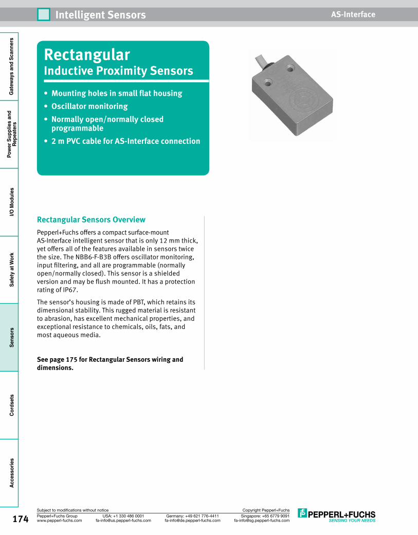
174 Singapore: +65 6779 [email protected]
USA: +1 330 486 [email protected]
Germany: +49 621 [email protected]
Pepperl+Fuchs Groupwww.pepperl-fuchs.com
Subject to modifications without notice Copyright Pepperl+Fuchs
Intelligent Sensors AS-InterfaceG
atew
ays
and
Scan
ners
Pow
er S
uppl
ies
and
Repe
ater
sI/O
Mod
ules
Safe
ty a
t Wor
kSe
nsor
sCo
rdse
tsAc
cess
orie
s
RectangularInductive Proximity Sensors• Mountingholesinsmallflathousing• Oscillatormonitoring• Normallyopen/normallyclosed
programmable• 2mPVCcableforAS-Interfaceconnection
Rectangular Sensors OverviewPepperl+Fuchs offers a compact surface-mount AS-Interface intelligent sensor that is only 12 mm thick, yet offers all of the features available in sensors twice the size. The NBB6-F-B3B offers oscillator monitoring, input filtering, and all are programmable (normally open/normally closed). This sensor is a shielded version and may be flush mounted. It has a protection rating of IP67.
The sensor’s housing is made of PBT, which retains its dimensional stability. This rugged material is resistant to abrasion, has excellent mechanical properties, and exceptional resistance to chemicals, oils, fats, and most aqueous media.
See page 175 for Rectangular Sensors wiring and dimensions.
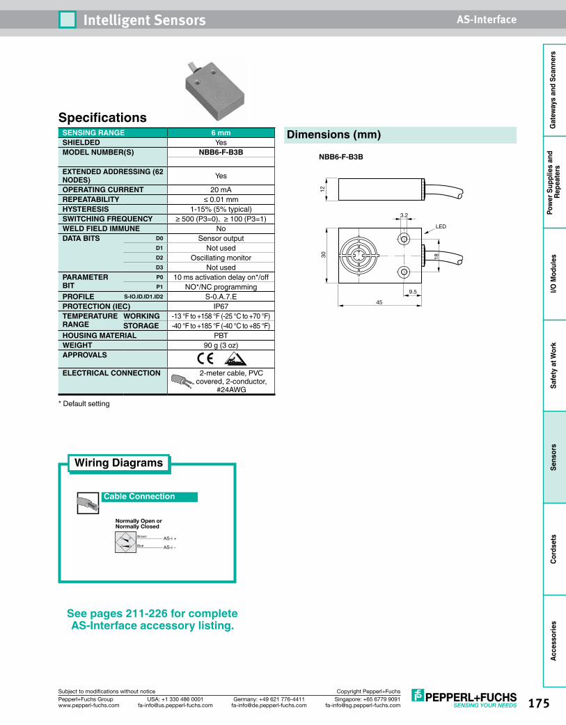
175Singapore: +65 6779 [email protected]
USA: +1 330 486 [email protected]
Germany: +49 621 [email protected]
Pepperl+Fuchs Groupwww.pepperl-fuchs.com
Subject to modifications without notice Copyright Pepperl+Fuchs
Intelligent Sensors AS-Interface
Gat
eway
s an
d Sc
anne
rsPo
wer
Sup
plie
s an
d Re
peat
ers
I/O M
odul
esSa
fety
at W
ork
Sens
ors
Cord
sets
Acce
ssor
ies
SpecificationsSENSING RANGE 6 mmSHIELDED YesMODEL NUMBER(S) NBB6-F-B3B
EXTENDED ADDRESSING (62 NODES) Yes
OPERATING CURRENT 20 mAREPEATABILITY ≤ 0.01 mmHYSTERESIS 1-15% (5% typical)SWITCHING FREQUENCY ≥ 500 (P3=0), ≥ 100 (P3=1)WELD FIELD IMMUNE NoDATA BITS D0 Sensor output
D1 Not usedD2 Oscillating monitorD3 Not used
PARAMETER BIT
P0 10 ms activation delay on*/offP1 NO*/NC programming
PROFILE S-IO.ID.ID1.ID2 S-0.A.7.EPROTECTION (IEC) IP67TEMPERATURE RANGE
WORKING -13 °F to +158 °F (-25 °C to +70 °F)STORAGE -40 °F to +185 °F (-40 °C to +85 °F)
HOUSING MATERIAL PBTWEIGHT 90 g (3 oz)APPROVALS
ELECTRICAL CONNECTION 2-meter cable, PVC covered, 2-conductor,
#24AWG
* Default setting
Wiring Diagrams
Cable Connection
AS-i +
AS-i -
Brown
Blue
Normally Open orNormally Closed
Dimensions (mm)
18
9.5
45
30
3.2
12
LED
NBB6-F-B3B
See pages 211-226 for complete AS-Interface accessory listing.
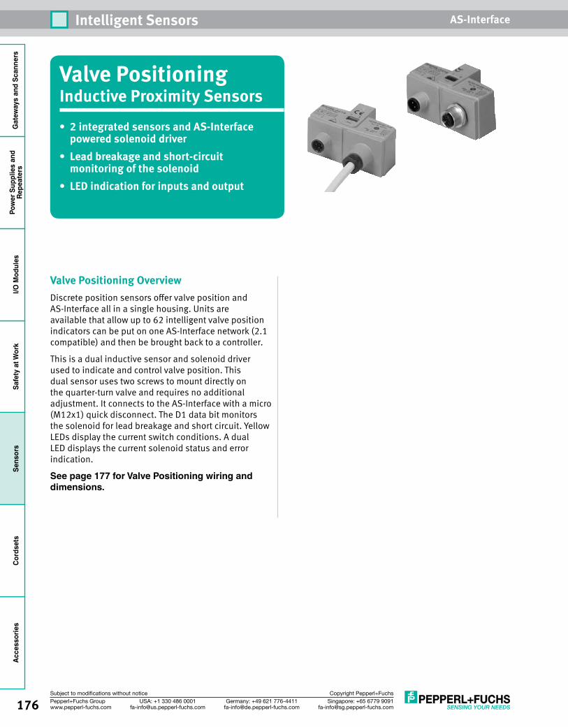
176 Singapore: +65 6779 [email protected]
USA: +1 330 486 [email protected]
Germany: +49 621 [email protected]
Pepperl+Fuchs Groupwww.pepperl-fuchs.com
Subject to modifications without notice Copyright Pepperl+Fuchs
Intelligent Sensors AS-InterfaceG
atew
ays
and
Scan
ners
Pow
er S
uppl
ies
and
Repe
ater
sI/O
Mod
ules
Safe
ty a
t Wor
kSe
nsor
sCo
rdse
tsAc
cess
orie
s
Valve PositioningInductive Proximity Sensors• 2integratedsensorsandAS-Interface
powered solenoid driver• Leadbreakageandshort-circuit
monitoring of the solenoid• LEDindicationforinputsandoutput
Valve Positioning OverviewDiscrete position sensors offer valve position and AS-Interface all in a single housing. Units are available that allow up to 62 intelligent valve position indicators can be put on one AS-Interface network (2.1 compatible) and then be brought back to a controller.
This is a dual inductive sensor and solenoid driver used to indicate and control valve position. This dual sensor uses two screws to mount directly on the quarter-turn valve and requires no additional adjustment. It connects to the AS-Interface with a micro (M12x1) quick disconnect. The D1 data bit monitors the solenoid for lead breakage and short circuit. Yellow LEDs display the current switch conditions. A dual LED displays the current solenoid status and error indication.
See page 177 for Valve Positioning wiring and dimensions.
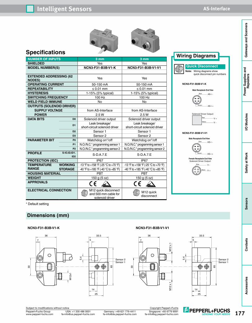
177Singapore: +65 6779 [email protected]
USA: +1 330 486 [email protected]
Germany: +49 621 [email protected]
Pepperl+Fuchs Groupwww.pepperl-fuchs.com
Subject to modifications without notice Copyright Pepperl+Fuchs
Intelligent Sensors AS-Interface
Gat
eway
s an
d Sc
anne
rsPo
wer
Sup
plie
s an
d Re
peat
ers
I/O M
odul
esSa
fety
at W
ork
Sens
ors
Cord
sets
Acce
ssor
ies
Wiring Diagrams
Quick DisconnectNote: Wiring diagrams show quick disconnect pin numbers
1 2
4 3
Brown
Blue
AS-i +
AS-i -
Male Receptacle End View
Solenoid Driver Output:
V +
V -
Red
Yellow
NCN3-F31-B3B-V1-K
SpecificationsNUMBER OF INPUTS 3 mm 3 mmSHIELDED Yes YesMODEL NUMBER(S) NCN3-F31-B3B-V1-K NCN3-F31-B3B-V1-V1
EXTENDED ADDRESSING (62 NODES) Yes Yes
OPERATING CURRENT 50-150 mA 50-150 mAREPEATABILITY ≤ 0.01 mm ≤ 0.01 mmHYSTERESIS 1-15% (5% typical) 1-15% (5% typical)SWITCHING FREQUENCY 100 Hz 100 HzWELD FIELD IMMUNE No NoOUTPUTS (SOLENOID DRIVER)
SUPPLY VOLTAGE from AS-Interface from AS-InterfacePOWER 2.5 W 2.5 W
DATA BITS D0 Solenoid driver output Solenoid driver outputD1 Leak breakage/
short-circuit solenoid driverLeak breakage/
short-circuit solenoid driverD2 Sensor 1 Sensor 1D3 Sensor 2 Sensor 2
PARAMETER BIT P0 Watchdog on*/off Watchdog on*/offP1 N.O./N.C.* programming sensor 1 N.O./N.C.* programming sensor 1P2 N.O./N.C.* programming sensor 2 N.O./N.C.* programming sensor 2
PROFILE S-IO.ID.ID1.ID2 S-D.A.7.E S-D.A.7.E
PROTECTION (IEC) IP67 IP67TEMPERATURE RANGE
WORKING -13 °F to +158 °F (-25 °C to +70 °F) -13 °F to +158 °F (-25 °C to +70 °F)STORAGE -40 °F to +185 °F (-40 °C to +85 °F) -40 °F to +185 °F (-40 °C to +85 °F)
HOUSING MATERIAL PBT PBTWEIGHT 150 g (5 oz) 150 g (5 oz)APPROVALS
ELECTRICAL CONNECTION M12 quick disconnect and 500 mm cable for
solenoid driverM12 quick disconnect
* Default setting
NCN3-F31-B3B-V1-V1
1 2
4 3
Brown
Blue
AS-i +
AS-i -
12
43 Black
Blue
V +
V -
Male Receptacle End View
Female Receptacle End ViewSolenoid Driver Output:
Dimensions (mm)
Sensor 2Sensor 1
5.4
7
36
30 65
14
25
33.55
M12
x1
NCN3-F31-B3B-V1-K NCN3-F31-B3B-V1-V1
Sensor 2Sensor 1
5.4
7
36
30 65
14
25
33.55
M12
x 1
M12
x 1
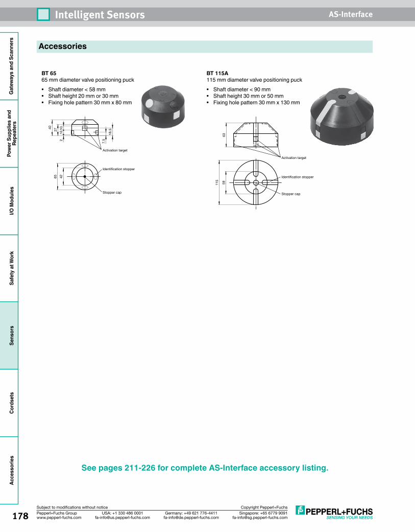
178 Singapore: +65 6779 [email protected]
USA: +1 330 486 [email protected]
Germany: +49 621 [email protected]
Pepperl+Fuchs Groupwww.pepperl-fuchs.com
Subject to modifications without notice Copyright Pepperl+Fuchs
Intelligent Sensors AS-InterfaceG
atew
ays
and
Scan
ners
Pow
er S
uppl
ies
and
Repe
ater
sI/O
Mod
ules
Safe
ty a
t Wor
kSe
nsor
sCo
rdse
tsAc
cess
orie
s
Accessories
BT 6565 mm diameter valve positioning puck• Shaft diameter < 58 mm• Shaft height 20 mm or 30 mm• Fixing hole pattern 30 mm x 80 mm
BT 115A115 mm diameter valve positioning puck• Shaft diameter < 90 mm• Shaft height 30 mm or 50 mm• Fixing hole pattern 30 mm x 130 mm
635911
5
Activation target
Stopper cap
Identification stopper
Activation target
Stopper cap
Identification stopper
18.5
7.5
27
40
210
10
65 42
See pages 211-226 for complete AS-Interface accessory listing.
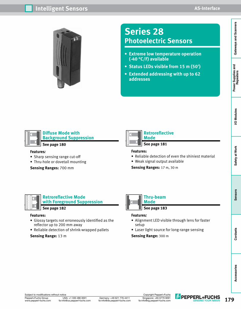
179Singapore: +65 6779 [email protected]
USA: +1 330 486 [email protected]
Germany: +49 621 [email protected]
Pepperl+Fuchs Groupwww.pepperl-fuchs.com
Subject to modifications without notice Copyright Pepperl+Fuchs
Intelligent Sensors AS-Interface
Gat
eway
s an
d Sc
anne
rsPo
wer
Sup
plie
s an
d Re
peat
ers
I/O M
odul
esSa
fety
at W
ork
Sens
ors
Cord
sets
Acce
ssor
ies
Series 28Photoelectric Sensors• Extremelowtemperatureoperation
(-40 °C/F) available• StatusLEDsvisiblefrom15m(50')• Extendedaddressingwithupto62
addresses
Thru-beam Mode See page 183
Features:• Alignment LED visible through lens for faster
setup• Laser light source for long-range sensingSensing Range: 300 m
Retroreflective Mode See page 181
Features:• Reliable detection of even the shiniest material• Weak signal output availableSensing Ranges: 17 m, 30 m
DiffuseModewith BackgroundSuppression See page 180
Features:• Sharp sensing range cut-off• Thru-hole or dovetail mountingSensing Ranges: 700 mm
RetroreflectiveMode with Foreground SuppressionSee page 182
Features:• Glossy targets not erroneously identified as the
reflector up to 200 mm away• Reliable detection of shrink-wrapped palletsSensing Range: 13 m
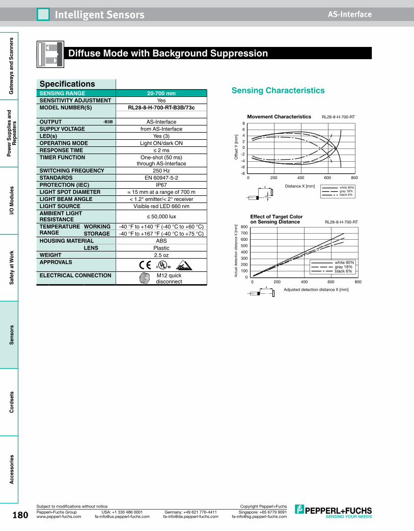
180 Singapore: +65 6779 [email protected]
USA: +1 330 486 [email protected]
Germany: +49 621 [email protected]
Pepperl+Fuchs Groupwww.pepperl-fuchs.com
Subject to modifications without notice Copyright Pepperl+Fuchs
Intelligent Sensors AS-InterfaceG
atew
ays
and
Scan
ners
Pow
er S
uppl
ies
and
Repe
ater
sI/O
Mod
ules
Safe
ty a
t Wor
kSe
nsor
sCo
rdse
tsAc
cess
orie
s
Diffuse Mode with Background Suppression
Sensing Characteristics
RL28-8-H-700-RT
0 200 400 600 800-8
-6
-4
-2
0
2
4
6
8
Movement Characteristics
x
y
white 90% gray 18%black 6%
Distance X [mm]
Off
set
Y [m
m]
0
100
200
300
400
500
600
700
800
0 200 400 600 800x
Adjusted detection distance X [mm]
Act
ual d
etec
tion
dis
tanc
e X
[mm
] RL28-8-H-700-RT
white 90% gray 18%black 6%
Effect of Target Color on Sensing Distance
SpecificationsSENSING RANGE 20-700 mmSENSITIVITY ADJUSTMENT YesMODEL NUMBER(S) RL28-8-H-700-RT-B3B/73c
OUTPUT -B3B AS-InterfaceSUPPLY VOLTAGE from AS-InterfaceLED(s) Yes (3)OPERATING MODE Light ON/dark ONRESPONSE TIME ≤ 2 msTIMER FUNCTION One-shot (50 ms)
through AS-InterfaceSWITCHING FREQUENCY 250 HzSTANDARDS EN 60947-5-2PROTECTION (IEC) IP67LIGHT SPOT DIAMETER ≈ 15 mm at a range of 700 mLIGHT BEAM ANGLE < 1.2° emitter/< 2° receiverLIGHT SOURCE Visible red LED 660 nmAMBIENT LIGHT RESISTANCE ≤ 50,000 lux
TEMPERATURE RANGE
WORKING -40 °F to +140 °F (-40 °C to +60 °C)STORAGE -40 °F to +167 °F (-40 °C to +75 °C)
HOUSING MATERIAL ABSLENS Plastic
WEIGHT 2.5 ozAPPROVALS
ELECTRICAL CONNECTION M12 quick disconnect
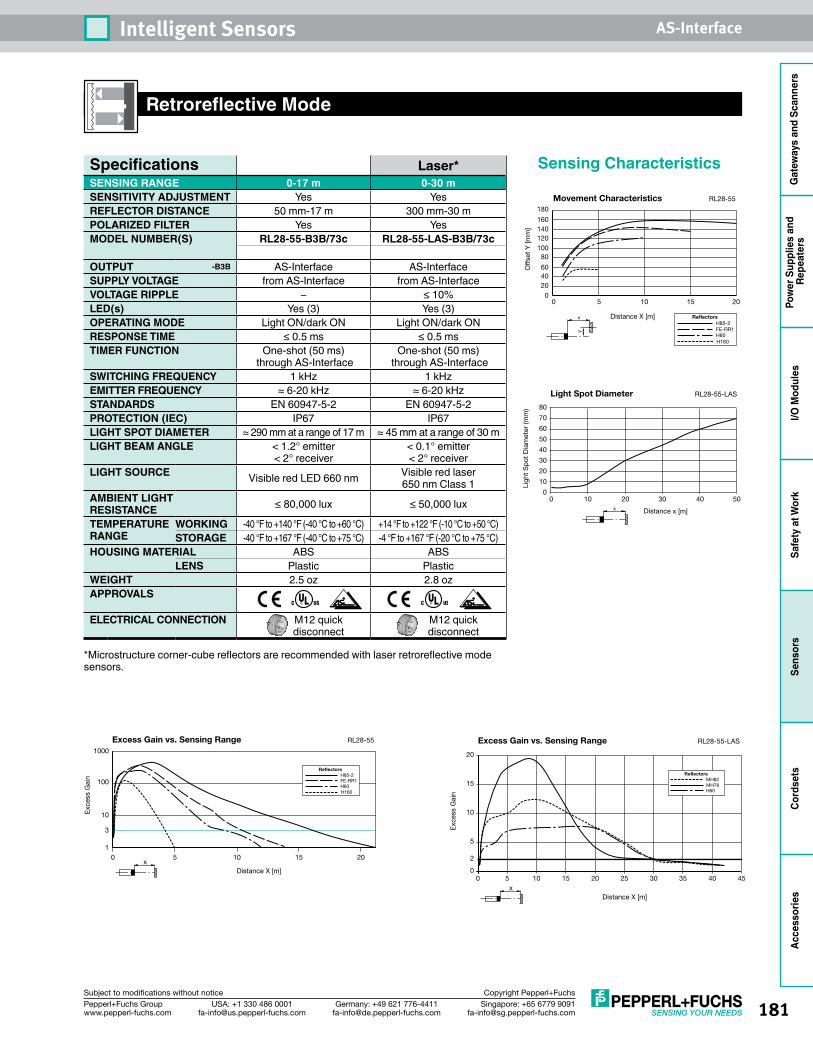
181Singapore: +65 6779 [email protected]
USA: +1 330 486 [email protected]
Germany: +49 621 [email protected]
Pepperl+Fuchs Groupwww.pepperl-fuchs.com
Subject to modifications without notice Copyright Pepperl+Fuchs
Intelligent Sensors AS-Interface
Gat
eway
s an
d Sc
anne
rsPo
wer
Sup
plie
s an
d Re
peat
ers
I/O M
odul
esSa
fety
at W
ork
Sens
ors
Cord
sets
Acce
ssor
ies
Retroreflective Mode
1050 15 201
10
100
1000
RL28-55
3
xDistance X [m]
Exc
ess
Gai
n
Excess Gain vs. Sensing Range
H85-2Reflectors
FE-RR1H60H160
0204060
80100120140160
180
1050 15 20
Movement Characteristics
Off
set
Y [m
m]
x
y
H85-2Reflectors
FE-RR1H60H160
Distance X [m]
RL28-55
xDistance X [m]
Exc
ess
Gai
n
RL28-55-LASExcess Gain vs. Sensing Range
20
15
10
5
2
00 5 10 15 20 25 30 35 40 45
MH82Reflectors
MH78H60
0 10 20 30 40 50
Distance x [m]x
Ligh
t S
pot
Dia
met
er (m
m)
Light Spot Diameter RL28-55-LAS
80
70
60
50
40
30
20
10
0
Sensing CharacteristicsSpecifications Laser*SENSING RANGE 0-17 m 0-30 mSENSITIVITY ADJUSTMENT Yes YesREFLECTOR DISTANCE 50 mm-17 m 300 mm-30 m POLARIZED FILTER Yes YesMODEL NUMBER(S) RL28-55-B3B/73c RL28-55-LAS-B3B/73c
OUTPUT -B3B AS-Interface AS-InterfaceSUPPLY VOLTAGE from AS-Interface from AS-InterfaceVOLTAGE RIPPLE – ≤ 10%LED(s) Yes (3) Yes (3)OPERATING MODE Light ON/dark ON Light ON/dark ONRESPONSE TIME ≤ 0.5 ms ≤ 0.5 msTIMER FUNCTION One-shot (50 ms)
through AS-InterfaceOne-shot (50 ms)
through AS-InterfaceSWITCHING FREQUENCY 1 kHz 1 kHz EMITTER FREQUENCY ≈ 6-20 kHz ≈ 6-20 kHzSTANDARDS EN 60947-5-2 EN 60947-5-2PROTECTION (IEC) IP67 IP67LIGHT SPOT DIAMETER ≈ 290 mm at a range of 17 m ≈ 45 mm at a range of 30 mLIGHT BEAM ANGLE < 1.2° emitter
< 2° receiver< 0.1° emitter < 2° receiver
LIGHT SOURCE Visible red LED 660 nm Visible red laser 650 nm Class 1
AMBIENT LIGHT RESISTANCE ≤ 80,000 lux ≤ 50,000 lux
TEMPERATURE RANGE
WORKING -40 °F to +140 °F (-40 °C to +60 °C) +14 °F to +122 °F (-10 °C to +50 °C)STORAGE -40 °F to +167 °F (-40 °C to +75 °C) -4 °F to +167 °F (-20 °C to +75 °C)
HOUSING MATERIAL ABS ABSLENS Plastic Plastic
WEIGHT 2.5 oz 2.8 ozAPPROVALS
ELECTRICAL CONNECTION M12 quick disconnect
M12 quick disconnect
*Microstructure corner-cube reflectors are recommended with laser retroreflective mode sensors.
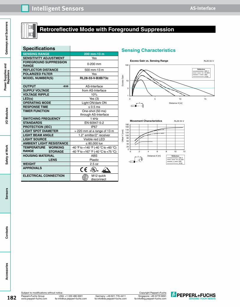
182 Singapore: +65 6779 [email protected]
USA: +1 330 486 [email protected]
Germany: +49 621 [email protected]
Pepperl+Fuchs Groupwww.pepperl-fuchs.com
Subject to modifications without notice Copyright Pepperl+Fuchs
Intelligent Sensors AS-InterfaceG
atew
ays
and
Scan
ners
Pow
er S
uppl
ies
and
Repe
ater
sI/O
Mod
ules
Safe
ty a
t Wor
kSe
nsor
sCo
rdse
tsAc
cess
orie
s
Retroreflective Mode with Foreground Suppression
Sensing Characteristics
0204060
80100120140160180
121086420
RL28-55-VMovement Characteristics
x
y
H85-2Reflectors
FE-RR1H60H160
Distance X [m]
Offs
et Y
[mm
]
1050 15
x Distance X [m]
1
10
3
100
Exc
ess
Gai
n
H85-2Reflectors
FE-RR1H60H160
Excess Gain vs. Sensing Range RL28-55-V
SpecificationsSENSING RANGE 200 mm-13 mSENSITIVITY ADJUSTMENT YesFOREGROUND SUPPRESSION RANGE 0-200 mm
REFLECTOR DISTANCE 500 mm-13 mPOLARIZED FILTER YesMODEL NUMBER(S) RL28-55-V-B3B/73c
OUTPUT -B3B AS-InterfaceSUPPLY VOLTAGE from AS-InterfaceVOLTAGE RIPPLE 10%LED(s) Yes (3)OPERATING MODE Light ON/dark ONRESPONSE TIME ≤ 0.5 msTIMER FUNCTION One-shot (50 ms)
through AS-InterfaceSWITCHING FREQUENCY 1 kHzSTANDARDS EN 60947-5-2PROTECTION (IEC) IP67LIGHT SPOT DIAMETER ≈ 220 mm at a range of 13 mLIGHT BEAM ANGLE 1.2° emitter/2° receiverLIGHT SOURCE Visible red LEDAMBIENT LIGHT RESISTANCE ≤ 80,000 luxTEMPERATURE RANGE
WORKING -40 °F to +140 °F (-40 °C to +60 °C)STORAGE -40 °F to +167 °F (-40 °C to +75 °C)
HOUSING MATERIAL ABSLENS Plastic
WEIGHT 2.5 ozAPPROVALS
ELECTRICAL CONNECTION M12 quick disconnect
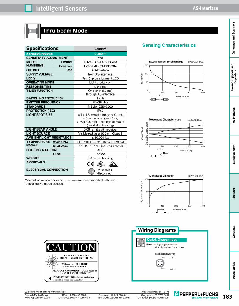
183Singapore: +65 6779 [email protected]
USA: +1 330 486 [email protected]
Germany: +49 621 [email protected]
Pepperl+Fuchs Groupwww.pepperl-fuchs.com
Subject to modifications without notice Copyright Pepperl+Fuchs
Intelligent Sensors AS-Interface
Gat
eway
s an
d Sc
anne
rsPo
wer
Sup
plie
s an
d Re
peat
ers
I/O M
odul
esSa
fety
at W
ork
Sens
ors
Cord
sets
Acce
ssor
ies
CAUTIONLASER RADIATION—
DO NOT STARE INTO BEAM
650 nm LASER LIGHT1 mW PEAK POWER
PRODUCT CONFORMS TO 21CFR1040CLASS II LASER PRODUCT
AVOID EXPOSURE – Laser radiationis emitted from this aperture
Thru-beam Mode
Sensing Characteristics
0 100 200 300 400x Distance X [m]
Excess Gain vs. Sensing Range LD28/LV28-LAS
1000
100
10
1
Exc
ess
Gai
n
x
y
Distance X [m]
Off
set
Y [m
m]
LD28/LV28-LASMovement Characteristics605040302010
0-10-20-30-40-50-60
0 100 200 300 400
Ligh
t S
pot
Dia
met
er [m
m]
Light Spot Diameter LD28/LV28-LAS
Distance X [m]x
0 100 200 300 400
100
10
1
Wiring Diagrams
Quick DisconnectNote: Wiring diagrams show quick disconnect pin numbers
Specifications Laser*SENSING RANGE 0-300 mSENSITIVITY ADJUSTMENT YesMODEL NUMBER(S)
Emitter LD28-LAS-F1-B3B/73cReceiver LV28-LAS-F1-B3B/73c
OUTPUT -B3B AS-InterfaceSUPPLY VOLTAGE from AS-InterfaceLED(s) Yes (3) plus alignment LEDOPERATING MODE Light on/dark onRESPONSE TIME ≤ 0.5 msTIMER FUNCTION One-shot (50 ms)
through AS-InterfaceSWITCHING FREQUENCY 1 kHzEMITTER FREQUENCY F1=25 kHzSTANDARDS NEMA ICS5-2000PROTECTION (IEC) IP67LIGHT SPOT SIZE ≈ 1 x 4.5 mm at a range of 0.1 m,
≈ 6 mm at a range of 5 m, ≈ 75 x 300 mm at a range of 300 m
(parallel to housing)LIGHT BEAM ANGLE 0.06° emitter/5° receiverLIGHT SOURCE Visible red laser 650 nm Class 2AMBIENT LIGHT RESISTANCE ≤ 50,000 luxTEMPERATURE RANGE
WORKING +14 °F to +122 °F (-10 °C to +50 °C)STORAGE -4 °F to +167 °F (-20 °C to +75 °C)
HOUSING MATERIAL ABSLENS Plastic
WEIGHT 2.8 oz per housingAPPROVALS
ELECTRICAL CONNECTION M12 quick disconnect
*Microstructure corner-cube reflectors are recommended with laser retroreflective mode sensors.
1 2
4 3
Brown
Blue
AS-i +
AS-i -
Male Receptacle End View
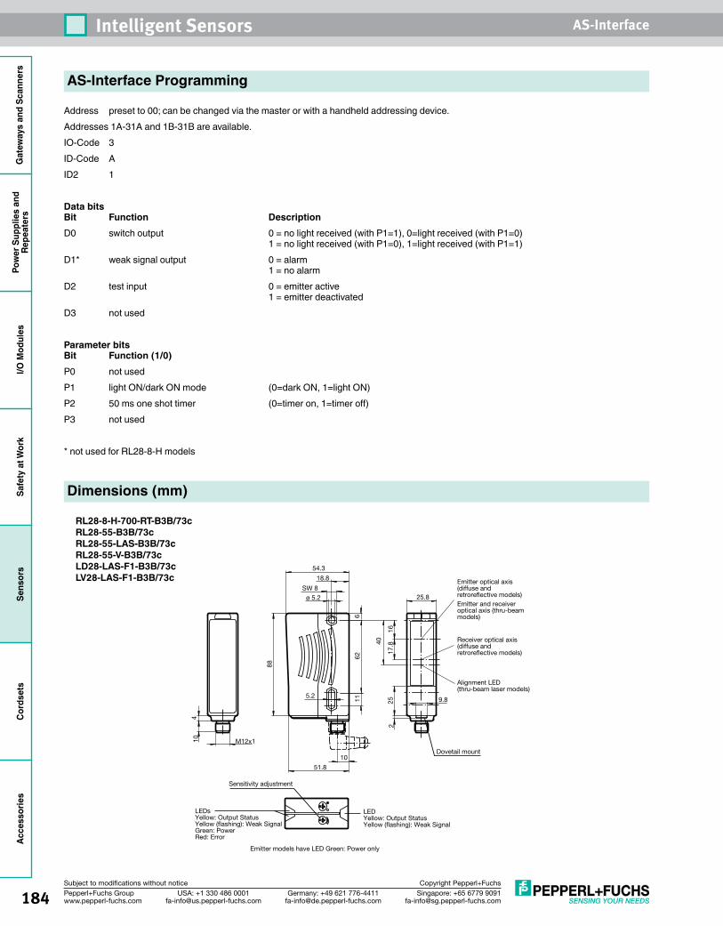
184 Singapore: +65 6779 [email protected]
USA: +1 330 486 [email protected]
Germany: +49 621 [email protected]
Pepperl+Fuchs Groupwww.pepperl-fuchs.com
Subject to modifications without notice Copyright Pepperl+Fuchs
Intelligent Sensors AS-InterfaceG
atew
ays
and
Scan
ners
Pow
er S
uppl
ies
and
Repe
ater
sI/O
Mod
ules
Safe
ty a
t Wor
kSe
nsor
sCo
rdse
tsAc
cess
orie
s
Address preset to 00; can be changed via the master or with a handheld addressing device. Addresses 1A-31A and 1B-31B are available. IO-Code 3ID-Code A ID2 1
Data bits Bit Function Description
D0 switch output 0 = no light received (with P1=1), 0=light received (with P1=0) 1 = no light received (with P1=0), 1=light received (with P1=1)D1* weak signal output 0 = alarm 1 = no alarm D2 test input 0 = emitter active 1 = emitter deactivated D3 not used
Parameter bits Bit Function (1/0)P0 not usedP1 light ON/dark ON mode (0=dark ON, 1=light ON)P2 50 ms one shot timer (0=timer on, 1=timer off)P3 not used
* not used for RL28-8-H models
AS-Interface Programming
5.2
1617
.840
116
62
225 9.8
25.8
54.3
18.8
SW 8
ø 5.2
51.8
10
M12x1
Sensitivity adjustment
Emitter models have LED Green: Power only
88
104
Dovetail mount
LEDYellow: Output StatusYellow (flashing): Weak Signal
LEDsYellow: Output StatusYellow (flashing): Weak SignalGreen: PowerRed: Error
Emitter optical axis (diffuse and retroreflective models)Emitter and receiver optical axis (thru-beam models)
Receiver optical axis (diffuse and retroreflective models)
Alignment LED(thru-beam laser models)
Dimensions (mm)
RL28-8-H-700-RT-B3B/73cRL28-55-B3B/73cRL28-55-LAS-B3B/73cRL28-55-V-B3B/73c LD28-LAS-F1-B3B/73cLV28-LAS-F1-B3B/73c
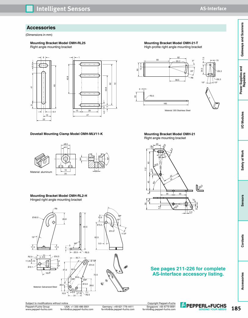
185Singapore: +65 6779 [email protected]
USA: +1 330 486 [email protected]
Germany: +49 621 [email protected]
Pepperl+Fuchs Groupwww.pepperl-fuchs.com
Subject to modifications without notice Copyright Pepperl+Fuchs
Intelligent Sensors AS-Interface
Gat
eway
s an
d Sc
anne
rsPo
wer
Sup
plie
s an
d Re
peat
ers
I/O M
odul
esSa
fety
at W
ork
Sens
ors
Cord
sets
Acce
ssor
ies
Accessories(Dimensions in mm)
Mounting Bracket Model OMH-RL25Right angle mounting bracket
8
6.415 28
941
43.8
43.8
63
6.4
12 47
22
1
4.3
5
62 72
Mounting Bracket Model OMH-21-THigh-profile right angle mounting bracket
9362
Ø5.3
Ø5.3
Ø5.3
Material: 303 Stainless Steel
1550
58.5R6
20º
5º
10º 10º
7.5
34.5
15
3
33 R3.5
165
Material: aluminum
90º
M4
M4
ø8.5
ø4.2
20
10
Dovetail Mounting Clamp Model OMH-MLV11-K Mounting Bracket Model OMH-21Right angle mounting bracket
5.3
R3.5
5.3
5.3
5.3
1530
5043
112
6243 60º
3 35 35
20
R10
5º
R10
R10 R6
5º
R6
5º5º
Mounting Bracket Model OMH-RL2-H Hinged right angle mounting bracket
R9
R5.5
Ø 60.2
Ø 6.1
18.0
Ø 6.3
Ø 5.0
Ø 10
Ø 5.2
Ø 5.3
15º
90º
11.6º
98º
15º
15º
15º
11.5
R2.5 316.5
11.25 0.10
11.53
26.8
25.5
35.7
72.5
57.2 62.0
28.0 28.0
139º 159ºR10
R2.5
Ø 5.05.0
3111.3
Ø 5.0
10.0 7.1
84.5
15.0
62.5
5.0
Material: Galvanized Steel
See pages 211-226 for complete AS-Interface accessory listing.
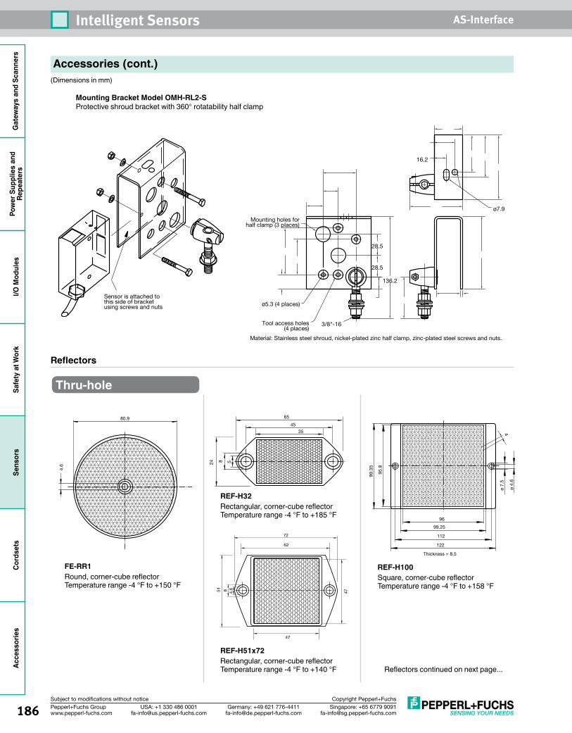
186 Singapore: +65 6779 [email protected]
USA: +1 330 486 [email protected]
Germany: +49 621 [email protected]
Pepperl+Fuchs Groupwww.pepperl-fuchs.com
Subject to modifications without notice Copyright Pepperl+Fuchs
Intelligent Sensors AS-InterfaceG
atew
ays
and
Scan
ners
Pow
er S
uppl
ies
and
Repe
ater
sI/O
Mod
ules
Safe
ty a
t Wor
kSe
nsor
sCo
rdse
tsAc
cess
orie
s
Accessories (cont.)(Dimensions in mm)
Mounting Bracket Model OMH-RL2-SProtective shroud bracket with 360° rotatability half clamp
136.2
28.5
28.5
16.2
Mounting holes for half clamp (3 places)
ø5.3 (4 places)
Tool access holes(4 places)
ø7.9
3/8"-16
Material: Stainless steel shroud, nickel-plated zinc half clamp, zinc-plated steel screws and nuts.
Sensor is attached to this side of bracket using screws and nuts
Reflectors
Thru-hole
4.6
80.9
FE-RR1Round, corner-cube reflector Temperature range -4 °F to +150 °F
24 8
65
4535
5
REF-H32Rectangular, corner-cube reflector Temperature range -4 °F to +185 °F
51 8
72
62
4.6
47
47
REF-H51x72Rectangular, corner-cube reflector Temperature range -4 °F to +140 °F
REF-H100Square, corner-cube reflector Temperature range -4 °F to +158 °F
96
99.25
112
95.8
4
122
99.3
5
ø 4.
6
Thickness = 8.5
ø 7.
5
Reflectors continued on next page...
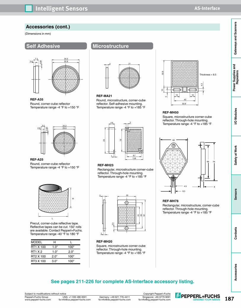
187Singapore: +65 6779 [email protected]
USA: +1 330 486 [email protected]
Germany: +49 621 [email protected]
Pepperl+Fuchs Groupwww.pepperl-fuchs.com
Subject to modifications without notice Copyright Pepperl+Fuchs
Intelligent Sensors AS-Interface
Gat
eway
s an
d Sc
anne
rsPo
wer
Sup
plie
s an
d Re
peat
ers
I/O M
odul
esSa
fety
at W
ork
Sens
ors
Cord
sets
Acce
ssor
ies
Accessories (cont.)(Dimensions in mm)
REF-A35Round, corner-cube reflector Temperature range -4 °F to +150 °F
0.85
34.532.8
7.42.8
MODEL H LRT1 X 100 1.0" 100"RT1 X 2 1.0" 2.0"RT2 X 100 2.0" 100"RT3 X 100 3.0" 100"
Precut, corner-cube reflective tape. Reflective tapes can be cut. 150’ rolls are available. Contact Pepperl+Fuchs. Temperature range -40 °F to 180 °F
H
L
Self Adhesive
REF-A25Round, corner-cube reflector Temperature range -4 °F to +150 °F
25.223.5
5.52.8
0.85
Microstructure
REF-MH23Rectangular, microstructure corner-cube reflector. Through-hole mounting. Temperature range -4 °F to +185 °F
1923
113.89.7
24.9
REF-MH20Square, microstructure corner-cube reflector. Through-hole mounting. Temperature range -4 °F to +185 °F
322620
3.5
20
2
3
REF-MA21Round, microstructure, corner-cube reflector. Self-adhesive mounting. Temperature range -4 °F to +185 °F
213
REF-MH50Square, microstructure corner-cube reflector. Through-hole mounting. Temperature range -4 °F to +185 °F
40
1010
5
1050
.9
4.3
50.9
Thickness = 8.5
REF-MH78Rectangular, microstructure, corner-cube reflector. Through-hole mounting. Temperature range -4 °F to +185 °F
60
8.5
4.5 8
68 78
See pages 211-226 for complete AS-Interface accessory listing.
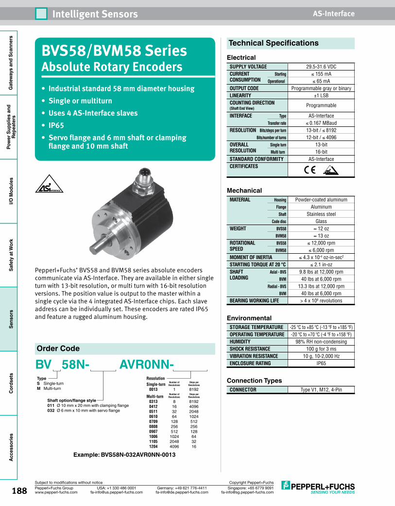
188 Singapore: +65 6779 [email protected]
USA: +1 330 486 [email protected]
Germany: +49 621 [email protected]
Pepperl+Fuchs Groupwww.pepperl-fuchs.com
Subject to modifications without notice Copyright Pepperl+Fuchs
Intelligent Sensors AS-InterfaceG
atew
ays
and
Scan
ners
Pow
er S
uppl
ies
and
Repe
ater
sI/O
Mod
ules
Safe
ty a
t Wor
kSe
nsor
sCo
rdse
tsAc
cess
orie
s
BVS58/BVM58 Series Absolute Rotary Encoders• Industrial standard 58 mm diameter housing• Singleormultiturn• Uses4AS-Interfaceslaves• IP65• Servoflangeand6mmshaftorclampingflangeand10mmshaft
Pepperl+Fuchs’ BVS58 and BVM58 series absolute encoders communicate via AS-Interface. They are available in either single turn with 13-bit resolution, or multi turn with 16-bit resolution versions. The position value is output to the master within a single cycle via the 4 integrated AS-Interface chips. Each slave address can be individually set. These encoders are rated IP65 and feature a rugged aluminum housing.
Order Code
BV 58N- AVR0NN- TypeS Single-turnM Multi-turn
Example: BVS58N-032AVR0NN-0013
Shaft option/flange style 011 Ø 10 mm x 20 mm with clamping flange032 Ø 6 mm x 10 mm with servo flange
Resolution Single-turn 0013 1 8192Multi-turn 0313 8 8192 0412 16 4096 0511 32 2048 0610 64 1024 0709 128 512 0808 256 256 0907 512 128 1006 1024 64 1105 2048 32 1204 4096 16
Number of Steps per Revolutions Revolutions
Number of Steps per Revolutions Revolutions
Technical Specifications
ElectricalSUPPLY VOLTAGECURRENT StartingCONSUMPTION Operational
OUTPUT CODELINEARITYCOUNTING DIRECTION (Shaft End View)
INTERFACE Type
Transfer rate
RESOLUTION Bits/steps per turn
Bits/number of turns
OVERALL Single turnRESOLUTION Multi turn
STANDARD CONFORMITYCERTIFICATES
29.5-31.6 VDC≤ 155 mA≤ 65 mA
Programmable gray or binary±1 LSB
Programmable
AS-Interface≤ 0.167 MBaud13-bit / ≤ 819212-bit / ≤ 4096
13-bit 16-bit
AS-Interface
MechanicalMATERIAL Housing
Flange
Shaft
Code disc
WEIGHT BVS58
BVM58
ROTATIONAL BVS58SPEED BVM58
MOMENT OF INERTIASTARTING TORQUE AT 20 °CSHAFT Axial - BVSLOADING BVM Radial - BVS
BVM
BEARING WORKING LIFE
Powder-coated aluminumAluminum
Stainless steelGlass≈ 12 oz≈ 13 oz
≤ 12,000 rpm≤ 6,000 rpm
≤ 4.3 x 10⁻⁴ oz-in-sec2
≤ 2.1 in-oz9.8 lbs at 12,000 rpm40 lbs at 6,000 rpm
13.3 lbs at 12,000 rpm40 lbs at 6,000 rpm> 4 x 10⁸ revolutions
EnvironmentalSTORAGE TEMPERATUREOPERATING TEMPERATUREHUMIDITYSHOCK RESISTANCEVIBRATION RESISTANCEENCLOSURE RATING
-25 ºC to +85 ºC (-13 ºF to +185 ºF)-20 ºC to +70 ºC (-4 ºF to +158 ºF)
98% RH non-condensing100 g for 3 ms
10 g, 10-2,000 HzIP65
Connection TypesCONNECTOR Type V1, M12, 4-Pin
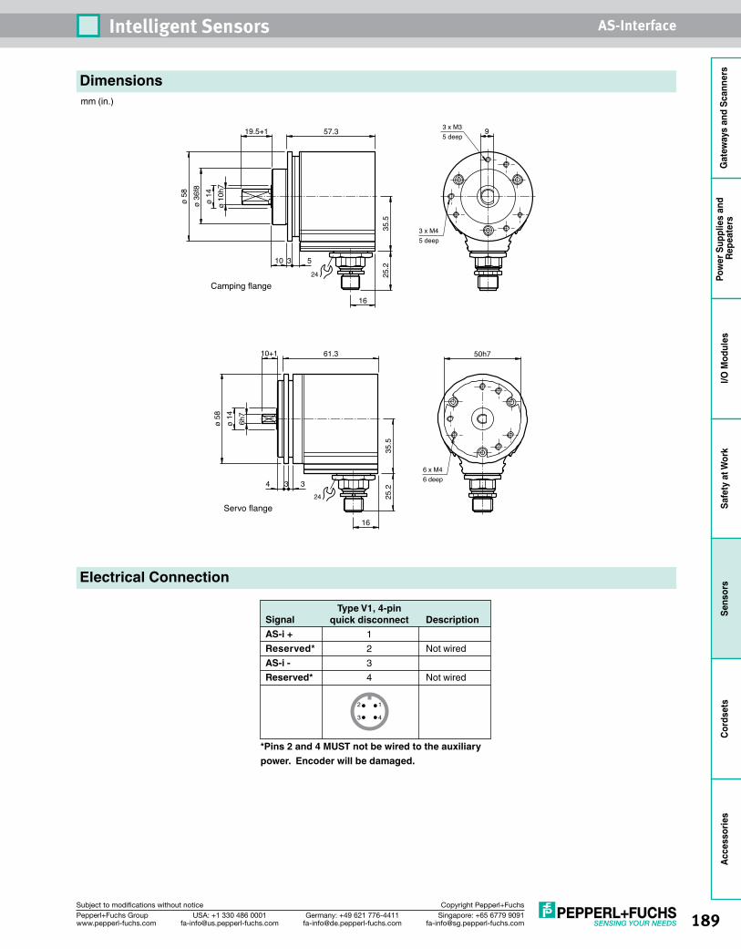
189Singapore: +65 6779 [email protected]
USA: +1 330 486 [email protected]
Germany: +49 621 [email protected]
Pepperl+Fuchs Groupwww.pepperl-fuchs.com
Subject to modifications without notice Copyright Pepperl+Fuchs
Intelligent Sensors AS-Interface
Gat
eway
s an
d Sc
anne
rsPo
wer
Sup
plie
s an
d Re
peat
ers
I/O M
odul
esSa
fety
at W
ork
Sens
ors
Cord
sets
Acce
ssor
ies
Electrical Connection
SignalAS-i +Reserved*AS-i -Reserved*
Type V1, 4-pinquick disconnect
1234
Description
Not wired
Not wired
3 4
2 1
*Pins 2 and 4 MUST not be wired to the auxiliary power. Encoder will be damaged.
Dimensionsmm (in.)
3 x M45 deep
Camping flange
3 x M35 deep
10 3 5
ø 10
h7ø
14ø
36f8
ø 58
57.3
16
35.5
919.5+1
25.2
24
6 x M46 deep
Servo flange
50h710+1
4 3 3
6h7
ø 14
ø 58
16
61.3
35.5
25.2
24

190 Singapore: +65 6779 [email protected]
USA: +1 330 486 [email protected]
Germany: +49 621 [email protected]
Pepperl+Fuchs Groupwww.pepperl-fuchs.com
Subject to modifications without notice Copyright Pepperl+Fuchs
Intelligent Sensors AS-InterfaceG
atew
ays
and
Scan
ners
Pow
er S
uppl
ies
and
Repe
ater
sI/O
Mod
ules
Safe
ty a
t Wor
kSe
nsor
sCo
rdse
tsAc
cess
orie
s
Addresses
When using an AS-Interface master or handheld programmer to change the slave addresses, it is absolutely essential to assign a different address to each of the four slaves.
Parameter BitsThe four parameter bits of slave A are used to set the parameters of the encoder. The parameter bits of slave B, C, and D are not used.
Data BitsFrom the AS-Interface master to the encoderData from the AS-Interface master is transferred to the encoder via slave A, which works bidirectionally. Slaves B, C, and D operate unidirectionally and can only send data.
When data bits D2 and D3 are changed from 01 to 10 or vice versa, the position data is saved in the encoder.
From the encoder to the AS-Interface masterParameter bit P1 of slave A is used to determine if the encoder transfers data to the AS-Interface master with or without flag bits.
P1 = 1: Transfer without flag bits
P1 = 0: Transfer with flag bits MA, MB, MC, MD
Slave A
P0 P1 P2 P3
Gray code Transfer with flag bits Count down with clockwise rotation Not used
Binary code Transfer without flag bits Count up with clockwise rotation Not used
Status of parameter bit
0
1
Slave A
D0/D1 D2/D3
Normal mode Position data is not saved
Rotary encoder is set to 1/4 of the single-turn resolution Position data is saved
Rotary encoder is set to 0 Position data is saved
Normal mode Position data is not saved
Status of D0/D1 or D2/D3
00
01
10
11
Slave A Slave B Slave C Slave D
D0 D1 D2 D3 D0 D1 D2 D3 D0 D1 D2 D3 D0 D1 D2
Bit 0 Bit 1 Bit 2 Bit 3 Bit 4 Bit 5 Bit 6 Bit 7 Bit 8 Bit 9 Bit 10 Bit 11 Bit 12 Not used!
D3
Slave A Slave B Slave C Slave D
D0 D1 D2 D3 D0 D1 D2 D3 D0 D1 D2 D3 D0 D1 D2
Bit 0 Bit 1 Bit 2 MA Bit 0 Bit 1 Bit 2 MB Bit 0 Bit 1 Bit 2 MC Bit 0 Bit 1 Bit 2
D3
MD
Programming
Slave A Slave B Slave C Slave D
1 2 3 4
7 0 0 0
F F F F
Preset address
IO code
ID code

191Singapore: +65 6779 [email protected]
USA: +1 330 486 [email protected]
Germany: +49 621 [email protected]
Pepperl+Fuchs Groupwww.pepperl-fuchs.com
Subject to modifications without notice Copyright Pepperl+Fuchs
Intelligent Sensors AS-Interface
Gat
eway
s an
d Sc
anne
rsPo
wer
Sup
plie
s an
d Re
peat
ers
I/O M
odul
esSa
fety
at W
ork
Sens
ors
Cord
sets
Acce
ssor
ies
Programming (continued)
Position data
Slave A Slave B Slave C Slave D
XXX0 XXX0 XXX0 XXX0
XXX1 XXX1 XXX1 XXX1
XXX0 XXX0 XXX0 XXX0
XXX1 XXX1 XXX1 XXX1
Cycle
1
2
3
4
etc.
Slave A Data bit D2
0
1
0
1
Operating ModesAddress assignments for the four slavesThe AS-Interface master accesses all slaves sequentially within an AS-Interface cycle to transfer output data to slave A or to read input data from the slaves. The single-turn absolute encoder uses four AS-Interface chips to transfer a position of 13 bits using 4 slave addresses.
These four slaves are queried sequentially and data can originate from any one of four different sampling times. To minimize this effect, sequential addresses (n, n+1, n+2, and n+3) should be assigned to slaves A, B, C, and D.
In addition, slave A is responsible for controlling the encoder’s functions. If the order of slaves is changed (D=n, C=n+1, B=n+2, A=n+3), the output word, which is supposed to be transmitted by the function control module of the absolute encoder, will not be transmitted until slaves D, C, and B have been read in. A memory command would then take effect only for slave A. The command would not affect the slaves that had already been read until the next read cycle. This change of slave order will result in data inconsistency.
Temporary st orage and transfer with flag bitsIf any data from the rotary encoder is interrupted during transmission, it is possible that some of the data transferred to the controller originates from a different position in the data word. The controller can check the data integrity for a single data word by comparing the four flag bits. Each slave can transfer one flag bit, making it possible for the control module to check which position data set an individual data set belongs to by comparing the 4 bits. Data bit D2 is used for this purpose. Using the flag bits reduces the size of the usable data from 16 bits to 12 bits.
See pages 211-226 for complete AS-Interface accessory listing.
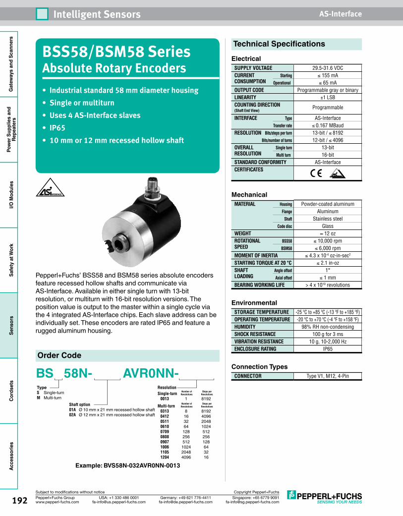
192 Singapore: +65 6779 [email protected]
USA: +1 330 486 [email protected]
Germany: +49 621 [email protected]
Pepperl+Fuchs Groupwww.pepperl-fuchs.com
Subject to modifications without notice Copyright Pepperl+Fuchs
Intelligent Sensors AS-InterfaceG
atew
ays
and
Scan
ners
Pow
er S
uppl
ies
and
Repe
ater
sI/O
Mod
ules
Safe
ty a
t Wor
kSe
nsor
sCo
rdse
tsAc
cess
orie
s
BSS58/BSM58 Series Absolute Rotary Encoders• Industrial standard 58 mm diameter housing• Singleormultiturn• Uses4AS-Interfaceslaves• IP65• 10mmor12mmrecessedhollowshaft
Pepperl+Fuchs’ BSS58 and BSM58 series absolute encoders feature recessed hollow shafts and communicate via AS-Interface. Available in either single turn with 13-bit resolution, or multiturn with 16-bit resolution versions. The position value is output to the master within a single cycle via the 4 integrated AS-Interface chips. Each slave address can be individually set. These encoders are rated IP65 and feature a rugged aluminum housing.
Order Code
BS 58N- AVR0NN- TypeS Single-turnM Multi-turn
Example: BVS58N-032AVR0NN-0013
Shaft option 01A Ø 10 mm x 21 mm recessed hollow shaft02A Ø 12 mm x 21 mm recessed hollow shaft
Resolution Single-turn 0013 1 8192Multi-turn 0313 8 8192 0412 16 4096 0511 32 2048 0610 64 1024 0709 128 512 0808 256 256 0907 512 128 1006 1024 64 1105 2048 32 1204 4096 16
Number of Steps per Revolutions Revolutions
Number of Steps per Revolutions Revolutions
Technical Specifications
ElectricalSUPPLY VOLTAGECURRENT StartingCONSUMPTION Operational
OUTPUT CODELINEARITYCOUNTING DIRECTION (Shaft End View)
INTERFACE Type
Transfer rate
RESOLUTION Bits/steps per turn
Bits/number of turns
OVERALL Single turnRESOLUTION Multi turn
STANDARD CONFORMITYCERTIFICATES
29.5-31.6 VDC≤ 155 mA≤ 65 mA
Programmable gray or binary±1 LSB
Programmable
AS-Interface≤ 0.167 MBaud13-bit / ≤ 819212-bit / ≤ 4096
13-bit 16-bit
AS-Interface
MechanicalMATERIAL Housing
Flange
Shaft
Code disc
WEIGHTROTATIONAL BSS58SPEED BSM58
MOMENT OF INERTIASTARTING TORQUE AT 20 °CSHAFT Angle offsetLOADING Axial offset
BEARING WORKING LIFE
Powder-coated aluminumAluminum
Stainless steelGlass≈ 12 oz
≤ 10,000 rpm≤ 6,000 rpm
≤ 4.3 x 10⁻⁴ oz-in-sec2
≤ 2.1 in-oz1°
≤ 1 mm> 4 x 10¹⁰ revolutions
EnvironmentalSTORAGE TEMPERATUREOPERATING TEMPERATUREHUMIDITYSHOCK RESISTANCEVIBRATION RESISTANCEENCLOSURE RATING
-25 ºC to +85 ºC (-13 ºF to +185 ºF)-20 ºC to +70 ºC (-4 ºF to +158 ºF)
98% RH non-condensing100 g for 3 ms
10 g, 10-2,000 HzIP65
Connection TypesCONNECTOR Type V1, M12, 4-Pin
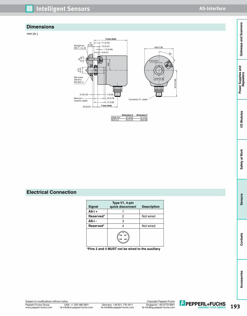
193Singapore: +65 6779 [email protected]
USA: +1 330 486 [email protected]
Germany: +49 621 [email protected]
Pepperl+Fuchs Groupwww.pepperl-fuchs.com
Subject to modifications without notice Copyright Pepperl+Fuchs
Intelligent Sensors AS-Interface
Gat
eway
s an
d Sc
anne
rsPo
wer
Sup
plie
s an
d Re
peat
ers
I/O M
odul
esSa
fety
at W
ork
Sens
ors
Cord
sets
Acce
ssor
ies
Electrical Connection
Set screwDIN 913M3 SW1.5
Straight pinDIN 7- 4 x 20
Minimum insertion depth
R22
11 (0.43)
8 (0.31)
ø4(0
.16)
ø12
(0.4
7)
2.5 (0.10) 7 (0.28)
9.5 (0.37)
52.9
(2.0
8)
ø58 (2.28)
60º
ø12 (0.47)
ø19.8 (0.78)
10(0.39)
12 (0.47)
1.5 (0.06)
21 (0.83)
20 (0.79)Connector V1, radial
Y (see table)
X (see table)
Dimension X Dimension YSingle-turn 67 (2.64) 41 (1.61)Multi-turn 94 (3.70) 68 (2.68)
SignalAS-i +Reserved*AS-i -Reserved*
Type V1, 4-pinquick disconnect
1234
Description
Not wired
Not wired
3 4
2 1
*Pins 2 and 4 MUST not be wired to the auxiliary power. Encoder will be damaged.
Dimensionsmm (in.)
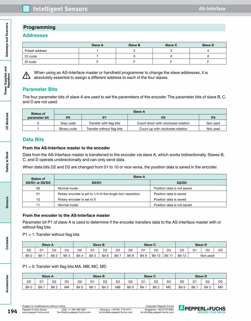
194 Singapore: +65 6779 [email protected]
USA: +1 330 486 [email protected]
Germany: +49 621 [email protected]
Pepperl+Fuchs Groupwww.pepperl-fuchs.com
Subject to modifications without notice Copyright Pepperl+Fuchs
Intelligent Sensors AS-InterfaceG
atew
ays
and
Scan
ners
Pow
er S
uppl
ies
and
Repe
ater
sI/O
Mod
ules
Safe
ty a
t Wor
kSe
nsor
sCo
rdse
tsAc
cess
orie
s
Addresses
When using an AS-Interface master or handheld programmer to change the slave addresses, it is absolutely essential to assign a different address to each of the four slaves.
Parameter BitsThe four parameter bits of slave A are used to set the parameters of the encoder. The parameter bits of slave B, C, and D are not used.
Data BitsFrom the AS-Interface master to the encoderData from the AS-Interface master is transferred to the encoder via slave A, which works bidirectionally. Slaves B, C, and D operate unidirectionally and can only send data.
When data bits D2 and D3 are changed from 01 to 10 or vice versa, the position data is saved in the encoder.
From the encoder to the AS-Interface masterParameter bit P1 of slave A is used to determine if the encoder transfers data to the AS-Interface master with or without flag bits.
P1 = 1: Transfer without flag bits
P1 = 0: Transfer with flag bits MA, MB, MC, MD
Slave A
P0 P1 P2 P3
Gray code Transfer with flag bits Count down with clockwise rotation Not used
Binary code Transfer without flag bits Count up with clockwise rotation Not used
Status of parameter bit
0
1
Slave A
D0/D1 D2/D3
Normal mode Position data is not saved
Rotary encoder is set to 1/4 of the single-turn resolution Position data is saved
Rotary encoder is set to 0 Position data is saved
Normal mode Position data is not saved
Status of D0/D1 or D2/D3
00
01
10
11
Slave A Slave B Slave C Slave D
D0 D1 D2 D3 D0 D1 D2 D3 D0 D1 D2 D3 D0 D1 D2
Bit 0 Bit 1 Bit 2 Bit 3 Bit 4 Bit 5 Bit 6 Bit 7 Bit 8 Bit 9 Bit 10 Bit 11 Bit 12 Not used!
D3
Slave A Slave B Slave C Slave D
D0 D1 D2 D3 D0 D1 D2 D3 D0 D1 D2 D3 D0 D1 D2
Bit 0 Bit 1 Bit 2 MA Bit 0 Bit 1 Bit 2 MB Bit 0 Bit 1 Bit 2 MC Bit 0 Bit 1 Bit 2
D3
MD
Slave A Slave B Slave C Slave D
1 2 3 4
7 0 0 0
F F F F
Preset address
IO code
ID code
Programming
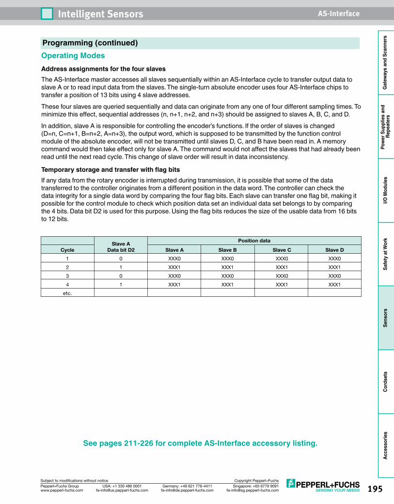
195Singapore: +65 6779 [email protected]
USA: +1 330 486 [email protected]
Germany: +49 621 [email protected]
Pepperl+Fuchs Groupwww.pepperl-fuchs.com
Subject to modifications without notice Copyright Pepperl+Fuchs
Intelligent Sensors AS-Interface
Gat
eway
s an
d Sc
anne
rsPo
wer
Sup
plie
s an
d Re
peat
ers
I/O M
odul
esSa
fety
at W
ork
Sens
ors
Cord
sets
Acce
ssor
ies
Programming (continued)
Position data
Slave A Slave B Slave C Slave D
XXX0 XXX0 XXX0 XXX0
XXX1 XXX1 XXX1 XXX1
XXX0 XXX0 XXX0 XXX0
XXX1 XXX1 XXX1 XXX1
Cycle
1
2
3
4
etc.
Slave A Data bit D2
0
1
0
1
Operating ModesAddress assignments for the four slavesThe AS-Interface master accesses all slaves sequentially within an AS-Interface cycle to transfer output data to slave A or to read input data from the slaves. The single-turn absolute encoder uses four AS-Interface chips to transfer a position of 13 bits using 4 slave addresses.
These four slaves are queried sequentially and data can originate from any one of four different sampling times. To minimize this effect, sequential addresses (n, n+1, n+2, and n+3) should be assigned to slaves A, B, C, and D.
In addition, slave A is responsible for controlling the encoder’s functions. If the order of slaves is changed (D=n, C=n+1, B=n+2, A=n+3), the output word, which is supposed to be transmitted by the function control module of the absolute encoder, will not be transmitted until slaves D, C, and B have been read in. A memory command would then take effect only for slave A. The command would not affect the slaves that had already been read until the next read cycle. This change of slave order will result in data inconsistency.
Temporary st orage and transfer with flag bitsIf any data from the rotary encoder is interrupted during transmission, it is possible that some of the data transferred to the controller originates from a different position in the data word. The controller can check the data integrity for a single data word by comparing the four flag bits. Each slave can transfer one flag bit, making it possible for the control module to check which position data set an individual data set belongs to by comparing the 4 bits. Data bit D2 is used for this purpose. Using the flag bits reduces the size of the usable data from 16 bits to 12 bits.
See pages 211-226 for complete AS-Interface accessory listing.

196 Singapore: +65 6779 [email protected]
USA: +1 330 486 [email protected]
Germany: +49 621 [email protected]
Pepperl+Fuchs Groupwww.pepperl-fuchs.com
Subject to modifications without notice Copyright Pepperl+Fuchs
Intelligent Sensors AS-InterfaceG
atew
ays
and
Scan
ners
Pow
er S
uppl
ies
and
Repe
ater
sI/O
Mod
ules
Safe
ty a
t Wor
kSe
nsor
sCo
rdse
tsAc
cess
orie
s
Notes
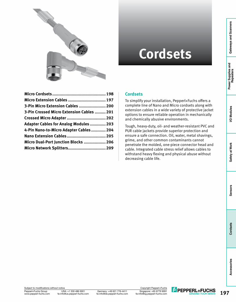
197Singapore: +65 6779 [email protected]
USA: +1 330 486 [email protected]
Germany: +49 621 [email protected]
Pepperl+Fuchs Groupwww.pepperl-fuchs.com
Subject to modifications without notice Copyright Pepperl+Fuchs
Gat
eway
s an
d Sc
anne
rsPo
wer
Sup
plie
s an
d Re
peat
ers
I/O M
odul
esSa
fety
at W
ork
Sens
ors
Cord
sets
Acce
ssor
ies
Micro Cordsets ............................................ 198Micro Extension Cables ............................... 1973-Pin Micro Extension Cables ...................... 2003-Pin Crossed Micro Extension Cables ......... 201Crossed Micro Adapter ................................ 202Adapter Cables for Analog Modules ............. 2034-Pin Nano-to-Micro Adapter Cables ............ 204Nano Extension Cables ................................ 205Micro Dual-Port Junction Blocks .................. 206Micro Network Splitters ............................... 209
Cordsets
CordsetsTo simplify your installation, Pepperl+Fuchs offers a complete line of Nano and Micro cordsets along with extension cables in a wide variety of protective jacket options to ensure reliable operation in mechanically and chemically abusive environments.
Tough, heavy-duty, oil- and weather-resistant PVC and PUR cable jackets provide superior protection and ensure a safe connection. Oil, water, metal shavings, grime, and other common contaminants cannot penetrate the molded, one-piece connector head and cable. Integrated cable stress relief allows cables to withstand heavy flexing and physical abuse without decreasing cable life.
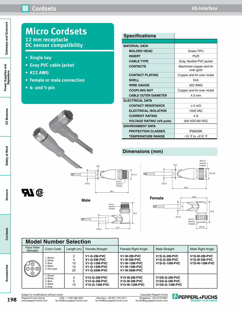
198
Cordsets AS-Interface
Singapore: +65 6779 [email protected]
USA: +1 330 486 [email protected]
Germany: +49 621 [email protected]
Pepperl+Fuchs Groupwww.pepperl-fuchs.com
Subject to modifications without notice Copyright Pepperl+Fuchs
Gat
eway
s an
d Sc
anne
rsPo
wer
Sup
plie
s an
dRe
peat
ers
I/O M
odul
esSa
fety
at W
ork
Sens
ors
Cord
sets
Acce
ssor
ies
Micro Cordsets12 mm receptacle DC sensor compatibility
• Singlekey• GrayPVCcablejacket• #22AWG• Femaleormaleconnection• 4-and5-pin
Dimensions (mm)
Specifications
MATERIAL DATAMOLDED HEAD Green TPUINSERT PURCABLE TYPE Gray, flexible PVC jacketCONTACTS Machined copper and tin
over goldCONTACT PLATING Copper and tin over nickelSHELL N/AWIRE GAUGE #22 AWGCOUPLING NUT Copper and tin over nickelCABLE OUTER DIAMETER 4.5 mm
ELECTRICAL DATA CONTACT RESISTANCE ≤ 5 mΩELECTRICAL ISOLATION 1500 VACCURRENT RATING 4 AVOLTAGE RATING (4/5 pole) 300 VDC/60 VDC
ENVIRONMENT DATAPROTECTION CLASSES IP68/69KTEMPERATURE RANGE -13 ˚F to +212 ˚F
Ø14.8
48.2
30.5
35.1
Ø10Ø10
Ø10.8M12x1external threads
Ø10.8
Ø10.8
Ø10.8
M12x1external threads
Ø14.8
45.3
45.3
M12x1internalthreads
M12x1internalthreads
27.8
Ø14.8
Male Female
Model Number Selection Face View (female) Color Code Length (m) Female Straight Female Right Angle Male Straight Male Right Angle
1
2
3
4
5
1. Brown2. White3. Blue4. Black5. Not used
25
101520
V1-G-2M-PVCV1-G-5M-PVCV1-G-10M-PVCV1-G-15M-PVCV1-G-20M-PVC
V1-W-2M-PVCV1-W-5M-PVCV1-W-10M-PVCV1-W-15M-PVCV1-W-20M-PVC
V1S-G-2M-PVCV1S-G-5M-PVCV1S-G-10M-PVC
V1S-W-2M-PVCV1S-W-5M-PVCV1S-W-10M-PVC
1. Brown2. White3. Blue4. Black5. Gray
25
10
V15-G-2M-PVCV15-G-5M-PVCV15-G-10M-PVC
V15-W-2M-PVCV15-W-5M-PVCV15-W-10M-PVC
V15S-G-2M-PVCV15S-G-5M-PVCV15S-G-10M-PVC
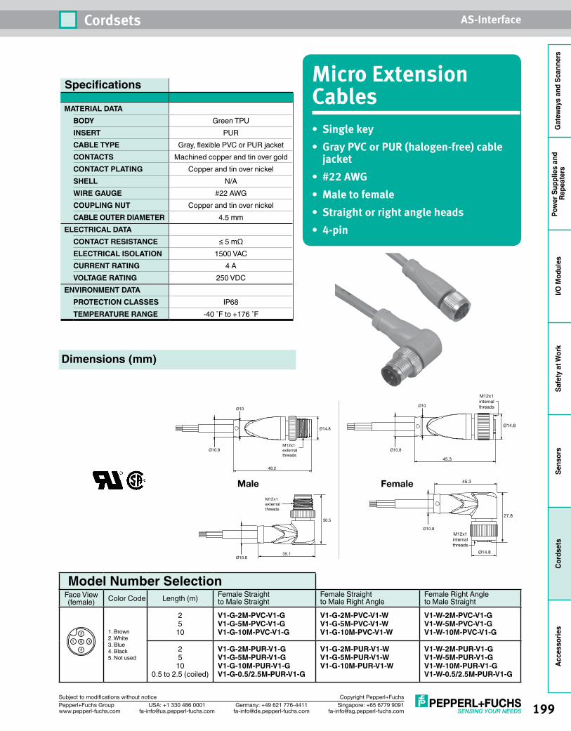
199
Cordsets AS-Interface
Singapore: +65 6779 [email protected]
USA: +1 330 486 [email protected]
Germany: +49 621 [email protected]
Pepperl+Fuchs Groupwww.pepperl-fuchs.com
Subject to modifications without notice Copyright Pepperl+Fuchs
Gat
eway
s an
d Sc
anne
rsPo
wer
Sup
plie
s an
d Re
peat
ers
I/O M
odul
esSa
fety
at W
ork
Sens
ors
Cord
sets
Acce
ssor
ies
Micro Extension Cables• Singlekey• GrayPVCorPUR(halogen-free)cablejacket
• #22AWG• Maletofemale• Straightorrightangleheads• 4-pin
Ø14.8
48.2
30.5
35.1
Ø10Ø10
Ø10.8M12x1external threads
Ø10.8
Ø10.8
Ø10.8
M12x1external threads
Ø14.8
45.3
45.3
M12x1internalthreads
M12x1internalthreads
27.8
Ø14.8
Male Female
Specifications
MATERIAL DATABODY Green TPUINSERT PURCABLE TYPE Gray, flexible PVC or PUR jacketCONTACTS Machined copper and tin over goldCONTACT PLATING Copper and tin over nickelSHELL N/AWIRE GAUGE #22 AWGCOUPLING NUT Copper and tin over nickelCABLE OUTER DIAMETER 4.5 mm
ELECTRICAL DATA CONTACT RESISTANCE ≤ 5 mΩELECTRICAL ISOLATION 1500 VACCURRENT RATING 4 AVOLTAGE RATING 250 VDC
ENVIRONMENT DATAPROTECTION CLASSES IP68TEMPERATURE RANGE -40 ˚F to +176 ˚F
Dimensions (mm)
Model Number Selection Face View (female) Color Code Length (m) Female Straight
to Male StraightFemale Straight to Male Right Angle
Female Right Angle to Male Straight
1
2
3
4
5
1. Brown2. White3. Blue4. Black5. Not used
25
10
V1-G-2M-PVC-V1-GV1-G-5M-PVC-V1-GV1-G-10M-PVC-V1-G
V1-G-2M-PVC-V1-WV1-G-5M-PVC-V1-WV1-G-10M-PVC-V1-W
V1-W-2M-PVC-V1-GV1-W-5M-PVC-V1-GV1-W-10M-PVC-V1-G
25
100.5 to 2.5 (coiled)
V1-G-2M-PUR-V1-GV1-G-5M-PUR-V1-GV1-G-10M-PUR-V1-GV1-G-0.5/2.5M-PUR-V1-G
V1-G-2M-PUR-V1-WV1-G-5M-PUR-V1-WV1-G-10M-PUR-V1-W
V1-W-2M-PUR-V1-GV1-W-5M-PUR-V1-GV1-W-10M-PUR-V1-GV1-W-0.5/2.5M-PUR-V1-G
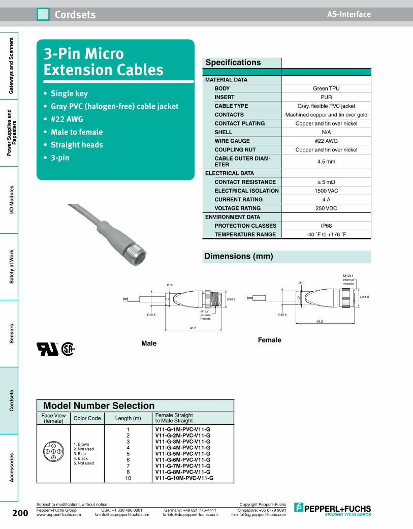
200
Cordsets AS-Interface
Singapore: +65 6779 [email protected]
USA: +1 330 486 [email protected]
Germany: +49 621 [email protected]
Pepperl+Fuchs Groupwww.pepperl-fuchs.com
Subject to modifications without notice Copyright Pepperl+Fuchs
Gat
eway
s an
d Sc
anne
rsPo
wer
Sup
plie
s an
dRe
peat
ers
I/O M
odul
esSa
fety
at W
ork
Sens
ors
Cord
sets
Acce
ssor
ies
3-Pin Micro Extension Cables• Singlekey• GrayPVC(halogen-free)cablejacket• #22AWG• Maletofemale• Straightheads• 3-pin
Dimensions (mm)
Model Number Selection Face View (female) Color Code Length (m) Female Straight
to Male Straight
1
2
3
4
5
1. Brown2. Not used3. Blue4. Black5. Not used
12345678
10
V11-G-1M-PVC-V11-G V11-G-2M-PVC-V11-G V11-G-3M-PVC-V11-G V11-G-4M-PVC-V11-G V11-G-5M-PVC-V11-G V11-G-6M-PVC-V11-G V11-G-7M-PVC-V11-G V11-G-8M-PVC-V11-G V11-G-10M-PVC-V11-G
Ø14.8
48.2
30.5
35.1
Ø10Ø10
Ø10.8M12x1external threads
Ø10.8
Ø10.8
Ø10.8
M12x1external threads
Ø14.8
45.3
45.3
M12x1internalthreads
M12x1internalthreads
27.8
Ø14.8
Male Female
Specifications
MATERIAL DATABODY Green TPUINSERT PURCABLE TYPE Gray, flexible PVC jacketCONTACTS Machined copper and tin over goldCONTACT PLATING Copper and tin over nickelSHELL N/AWIRE GAUGE #22 AWGCOUPLING NUT Copper and tin over nickelCABLE OUTER DIAM-ETER 4.5 mm
ELECTRICAL DATA CONTACT RESISTANCE ≤ 5 mΩELECTRICAL ISOLATION 1500 VACCURRENT RATING 4 AVOLTAGE RATING 250 VDC
ENVIRONMENT DATAPROTECTION CLASSES IP68TEMPERATURE RANGE -40 ˚F to +176 ˚F
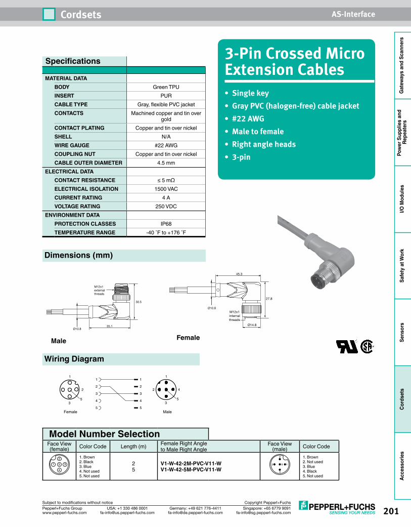
201
Cordsets AS-Interface
Singapore: +65 6779 [email protected]
USA: +1 330 486 [email protected]
Germany: +49 621 [email protected]
Pepperl+Fuchs Groupwww.pepperl-fuchs.com
Subject to modifications without notice Copyright Pepperl+Fuchs
Gat
eway
s an
d Sc
anne
rsPo
wer
Sup
plie
s an
d Re
peat
ers
I/O M
odul
esSa
fety
at W
ork
Sens
ors
Cord
sets
Acce
ssor
ies
3-Pin Crossed Micro Extension Cables• Singlekey• GrayPVC(halogen-free)cablejacket• #22AWG• Maletofemale• Rightangleheads• 3-pin
Dimensions (mm)
Model Number Selection Face View (female) Color Code Length (m) Female Right Angle
to Male Right AngleFace View
(male) Color Code
1
2
3
4
5
1. Brown2. Black3. Blue4. Not used5. Not used
25
V1-W-42-2M-PVC-V11-W V1-W-42-5M-PVC-V11-W
1
2
3
4
5
1. Brown2. Not used3. Blue4. Black5. Not used
Ø14.8
48.2
30.5
35.1
Ø10Ø10
Ø10.8M12x1external threads
Ø10.8
Ø10.8
Ø10.8
M12x1external threads
Ø14.8
45.3
45.3
M12x1internalthreads
M12x1internalthreads
27.8
Ø14.8
Male Female
Specifications
MATERIAL DATABODY Green TPUINSERT PURCABLE TYPE Gray, flexible PVC jacketCONTACTS Machined copper and tin over
goldCONTACT PLATING Copper and tin over nickelSHELL N/AWIRE GAUGE #22 AWGCOUPLING NUT Copper and tin over nickelCABLE OUTER DIAMETER 4.5 mm
ELECTRICAL DATA CONTACT RESISTANCE ≤ 5 mΩELECTRICAL ISOLATION 1500 VACCURRENT RATING 4 AVOLTAGE RATING 250 VDC
ENVIRONMENT DATAPROTECTION CLASSES IP68TEMPERATURE RANGE -40 ˚F to +176 ˚F
1
2 4
35
1
2
3
MaleFemale
5
1
2
3
4
5
1
2
3
4
5
Wiring Diagram
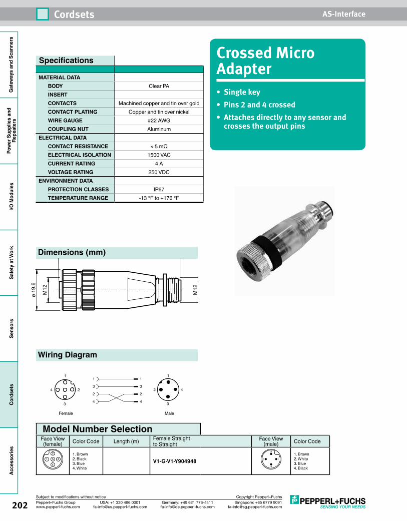
202
Cordsets AS-Interface
Singapore: +65 6779 [email protected]
USA: +1 330 486 [email protected]
Germany: +49 621 [email protected]
Pepperl+Fuchs Groupwww.pepperl-fuchs.com
Subject to modifications without notice Copyright Pepperl+Fuchs
Gat
eway
s an
d Sc
anne
rsPo
wer
Sup
plie
s an
dRe
peat
ers
I/O M
odul
esSa
fety
at W
ork
Sens
ors
Cord
sets
Acce
ssor
ies
Crossed Micro Adapter• Singlekey• Pins2and4crossed• Attachesdirectlytoanysensorandcrossestheoutputpins
Dimensions (mm)
Model Number Selection Face View (female) Color Code Length (m) Female Straight
to StraightFace View
(male) Color Code
1
2
3
4
51. Brown2. Black3. Blue4. White
V1-G-V1-Y904948 1
2
3
4
1. Brown2. White3. Blue4. Black
Specifications
MATERIAL DATABODY Clear PAINSERTCONTACTS Machined copper and tin over goldCONTACT PLATING Copper and tin over nickelWIRE GAUGE #22 AWGCOUPLING NUT Aluminum
ELECTRICAL DATA CONTACT RESISTANCE ≤ 5 mΩELECTRICAL ISOLATION 1500 VAC CURRENT RATING 4 AVOLTAGE RATING 250 VDC
ENVIRONMENT DATAPROTECTION CLASSES IP67TEMPERATURE RANGE -13 °F to +176 °F
Wiring Diagram
58.6
M12
ø 19
.6
M12
1
2 4
3
1
2
3
MaleFemale
1
3
2
4
1
3
2
4
4
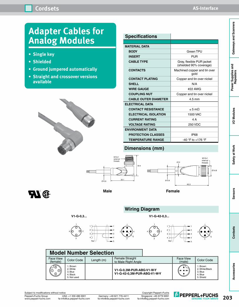
203
Cordsets AS-Interface
Singapore: +65 6779 [email protected]
USA: +1 330 486 [email protected]
Germany: +49 621 [email protected]
Pepperl+Fuchs Groupwww.pepperl-fuchs.com
Subject to modifications without notice Copyright Pepperl+Fuchs
Gat
eway
s an
d Sc
anne
rsPo
wer
Sup
plie
s an
d Re
peat
ers
I/O M
odul
esSa
fety
at W
ork
Sens
ors
Cord
sets
Acce
ssor
ies
Adapter Cables for Analog Modules• Singlekey• Shielded• Groundjumperedautomatically• Straightandcrossoverversionsavailable
Specifications
MATERIAL DATABODY Green TPUINSERT PURCABLE TYPE Gray, flexible PUR jacket
(shielded 90% coverage)CONTACTS Machined copper and tin over
goldCONTACT PLATING Copper and tin over nickelSHELL N/AWIRE GAUGE #22 AWGCOUPLING NUT Copper and tin over nickelCABLE OUTER DIAMETER 4.5 mm
ELECTRICAL DATA CONTACT RESISTANCE ≤ 5 mΩELECTRICAL ISOLATION 1500 VACCURRENT RATING 4 AVOLTAGE RATING 250 VDC
ENVIRONMENT DATAPROTECTION CLASSES IP68TEMPERATURE RANGE -40 °F to +176 °F
Dimensions (mm)
Model Number Selection Face View (female) Color Code Length (m) Female Straight
to Male Right AngleFace View
(male) Color Code
1
2
3
4
1. Brown2. White3. Blue4. Black5. Not used
V1-G-0,3M-PUR-ABG-V1-W-YV1-G-42-0,3M-PUR-ABG-V1-W-Y
1
2
3
4
5
1. Brown2. White/Black3. Blue4. Blue5. Shield
Wiring Diagram
30.5
35.1
Ø10
Ø10.8 Ø10.8
M12x1external threads
Ø14.8
45.3
M12x1internalthreads
Male Female
1
2 4
35
1
2
3
4
1
2
3
4
5
1
2
3
4
Nut
1
2 4
35
1
2
3
4
1
2
3
4
5
1
2
3
4
Nut
V1-G-0,3... V1-G-42-0,3...
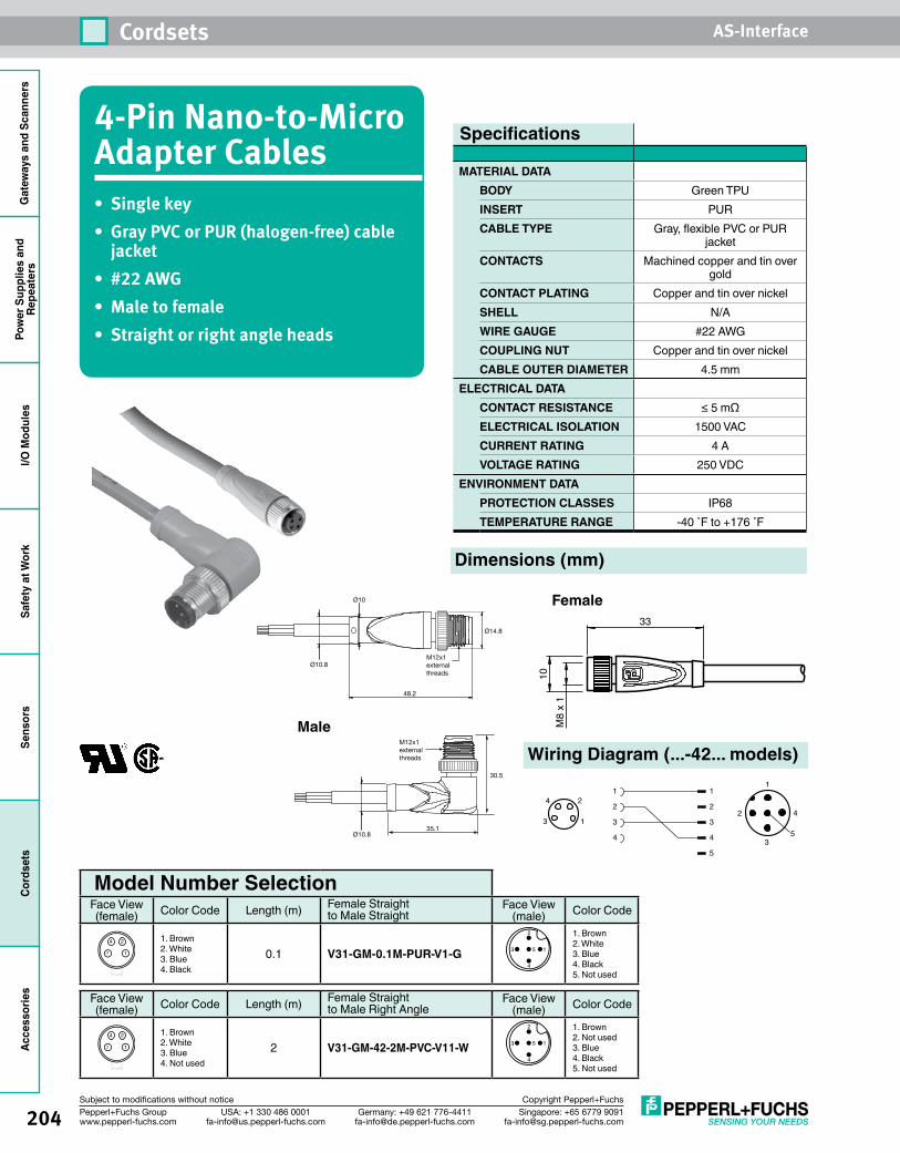
204
Cordsets AS-Interface
Singapore: +65 6779 [email protected]
USA: +1 330 486 [email protected]
Germany: +49 621 [email protected]
Pepperl+Fuchs Groupwww.pepperl-fuchs.com
Subject to modifications without notice Copyright Pepperl+Fuchs
Gat
eway
s an
d Sc
anne
rsPo
wer
Sup
plie
s an
dRe
peat
ers
I/O M
odul
esSa
fety
at W
ork
Sens
ors
Cord
sets
Acce
ssor
ies
4-Pin Nano-to-Micro Adapter Cables• Singlekey• GrayPVCorPUR(halogen-free)cablejacket
• #22AWG• Maletofemale• Straightorrightangleheads
Dimensions (mm)
Face View (female) Color Code Length (m) Female Straight
to Male Right AngleFace View
(male) Color Code
3
4 2
1
1. Brown2. White3. Blue4. Not used
2 V31-GM-42-2M-PVC-V11-W 1
2
3
4
5
1. Brown2. Not used3. Blue4. Black5. Not used
Model Number Selection Face View (female) Color Code Length (m) Female Straight
to Male StraightFace View
(male) Color Code
3
4 2
1
1. Brown2. White3. Blue4. Black
0.1 V31-GM-0.1M-PUR-V1-G 1
2
3
4
5
1. Brown2. White3. Blue4. Black5. Not used
Ø14.8
48.2
30.5
35.1
Ø10Ø10
Ø10.8M12x1external threads
Ø10.8
Ø10.8
Ø10.8
M12x1external threads
Ø14.8
45.3
45.3
M12x1internalthreads
M12x1internalthreads
27.8
Ø14.8
Male
Female
Specifications
MATERIAL DATABODY Green TPUINSERT PURCABLE TYPE Gray, flexible PVC or PUR
jacketCONTACTS Machined copper and tin over
goldCONTACT PLATING Copper and tin over nickelSHELL N/AWIRE GAUGE #22 AWGCOUPLING NUT Copper and tin over nickelCABLE OUTER DIAMETER 4.5 mm
ELECTRICAL DATA CONTACT RESISTANCE ≤ 5 mΩELECTRICAL ISOLATION 1500 VACCURRENT RATING 4 AVOLTAGE RATING 250 VDC
ENVIRONMENT DATAPROTECTION CLASSES IP68TEMPERATURE RANGE -40 ˚F to +176 ˚F
33
10M
8 x
1
Wiring Diagram (...-42... models)1
2 4
35
1
2
3
4
1
2
3
4
5
1
4 2
3
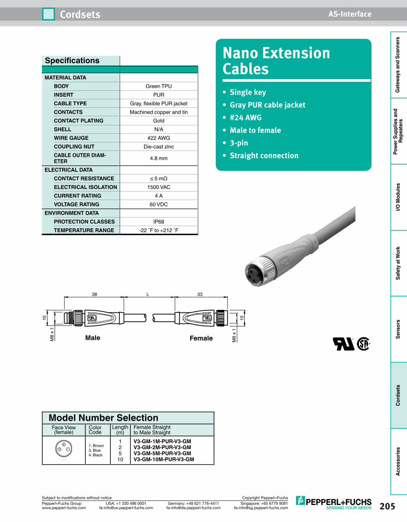
205
Cordsets AS-Interface
Singapore: +65 6779 [email protected]
USA: +1 330 486 [email protected]
Germany: +49 621 [email protected]
Pepperl+Fuchs Groupwww.pepperl-fuchs.com
Subject to modifications without notice Copyright Pepperl+Fuchs
Gat
eway
s an
d Sc
anne
rsPo
wer
Sup
plie
s an
d Re
peat
ers
I/O M
odul
esSa
fety
at W
ork
Sens
ors
Cord
sets
Acce
ssor
ies
L38
10
M8
x 1
33
10M
8 x
1
Male Female
Nano Extension Cables•Singlekey•GrayPURcablejacket•#24AWG• Maletofemale•3-pin• Straightconnection
Model Number Selection Face View (female)
Color Code
Length (m)
Female Straight to Male Straight
1
4
31. Brown3. Blue4. Black
125
10
V3-GM-1M-PUR-V3-GM V3-GM-2M-PUR-V3-GM V3-GM-5M-PUR-V3-GM V3-GM-10M-PUR-V3-GM
Specifications
MATERIAL DATABODY Green TPUINSERT PURCABLE TYPE Gray, flexible PUR jacketCONTACTS Machined copper and tinCONTACT PLATING GoldSHELL N/AWIRE GAUGE #22 AWGCOUPLING NUT Die-cast zincCABLE OUTER DIAM-ETER 4.8 mm
ELECTRICAL DATA CONTACT RESISTANCE ≤ 5 mΩELECTRICAL ISOLATION 1500 VACCURRENT RATING 4 AVOLTAGE RATING 60 VDC
ENVIRONMENT DATAPROTECTION CLASSES IP68TEMPERATURE RANGE -22 ˚F to +212 ˚F
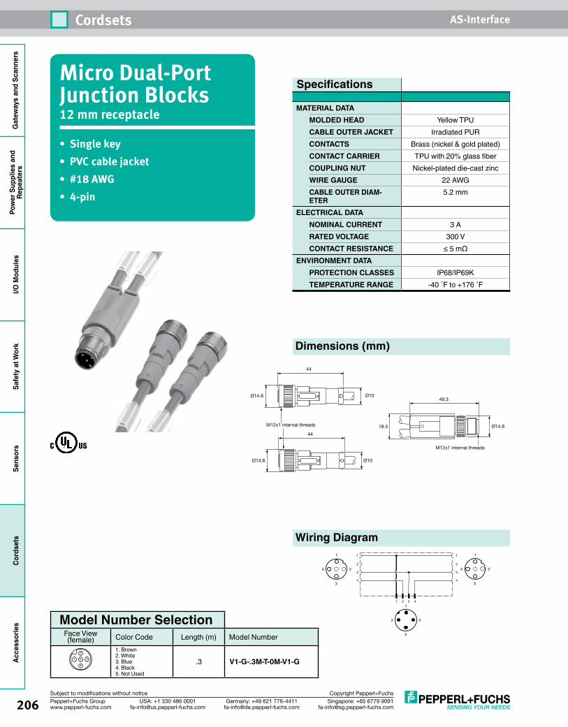
206
Cordsets AS-Interface
Singapore: +65 6779 [email protected]
USA: +1 330 486 [email protected]
Germany: +49 621 [email protected]
Pepperl+Fuchs Groupwww.pepperl-fuchs.com
Subject to modifications without notice Copyright Pepperl+Fuchs
Gat
eway
s an
d Sc
anne
rsPo
wer
Sup
plie
s an
dRe
peat
ers
I/O M
odul
esSa
fety
at W
ork
Sens
ors
Cord
sets
Acce
ssor
ies
Micro Dual-Port Junction Blocks12 mm receptacle
• Singlekey• PVCcablejacket• #18AWG• 4-pin
1
1 2 3 4
2
3
1
2
4 4
3
1
2 4
3
2
1
4
3
2
1
4
3
Model Number Selection Face View (female) Color Code Length (m) Model Number
1
2
3
4
5
1. Brown2. White3. Blue4. Black5. Not Used
.3 V1-G-.3M-T-0M-V1-G
Dimensions (mm)
Wiring Diagram
44
Ø10
Ø10
18.5 Ø14.8
49.3Ø14.8
Ø14.8
44
M12x1 internal threads
M12x1 internal threads
Specifications
MATERIAL DATAMOLDED HEAD Yellow TPUCABLE OUTER JACKET Irradiated PURCONTACTS Brass (nickel & gold plated)CONTACT CARRIER TPU with 20% glass fiberCOUPLING NUT Nickel-plated die-cast zincWIRE GAUGE 22 AWGCABLE OUTER DIAM-ETER
5.2 mm
ELECTRICAL DATA NOMINAL CURRENT 3 ARATED VOLTAGE 300 VCONTACT RESISTANCE ≤ 5 mΩ
ENVIRONMENT DATAPROTECTION CLASSES IP68/IP69KTEMPERATURE RANGE -40 ˚F to +176 ˚F
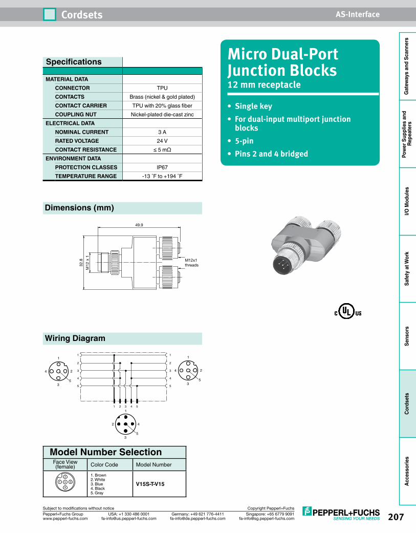
207
Cordsets AS-Interface
Singapore: +65 6779 [email protected]
USA: +1 330 486 [email protected]
Germany: +49 621 [email protected]
Pepperl+Fuchs Groupwww.pepperl-fuchs.com
Subject to modifications without notice Copyright Pepperl+Fuchs
Gat
eway
s an
d Sc
anne
rsPo
wer
Sup
plie
s an
d Re
peat
ers
I/O M
odul
esSa
fety
at W
ork
Sens
ors
Cord
sets
Acce
ssor
ies
Micro Dual-Port Junction Blocks12 mm receptacle
• Singlekey• Fordual-inputmultiportjunction
blocks• 5-pin• Pins2and4bridged
Dimensions (mm)
Model Number Selection Face View (female) Color Code Model Number
1
2
3
4
5
1. Brown2. White3. Blue4. Black5. Gray
V15S-T-V15
Wiring Diagram
49.9
32.8
M12
x 1
M12x1threads
Specifications
MATERIAL DATACONNECTOR TPUCONTACTS Brass (nickel & gold plated)CONTACT CARRIER TPU with 20% glass fiberCOUPLING NUT Nickel-plated die-cast zinc
ELECTRICAL DATA NOMINAL CURRENT 3 ARATED VOLTAGE 24 VCONTACT RESISTANCE ≤ 5 mΩ
ENVIRONMENT DATAPROTECTION CLASSES IP67TEMPERATURE RANGE -13 ˚F to +194 ˚F
1
1 2 3 4 5
2
3
1
2
4 4
3
5 5
1
2 4
35
1
4
35
2
1
4
35
2
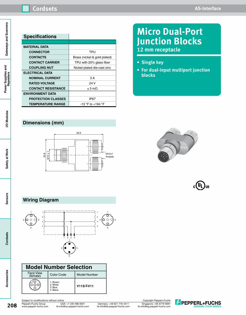
208
Cordsets AS-Interface
Singapore: +65 6779 [email protected]
USA: +1 330 486 [email protected]
Germany: +49 621 [email protected]
Pepperl+Fuchs Groupwww.pepperl-fuchs.com
Subject to modifications without notice Copyright Pepperl+Fuchs
Gat
eway
s an
d Sc
anne
rsPo
wer
Sup
plie
s an
dRe
peat
ers
I/O M
odul
esSa
fety
at W
ork
Sens
ors
Cord
sets
Acce
ssor
ies
Micro Dual-Port Junction Blocks12 mm receptacle
• Singlekey• Fordual-inputmultiportjunction
blocks
Dimensions (mm)
Model Number Selection Face View (female) Color Code Model Number
1
2
3
4
51. Brown2. White3. Blue4. Black
V11S-T-V11
Wiring Diagram
49.9
32.8
M12
x 1
M12x1threads
Specifications
MATERIAL DATACONNECTOR TPUCONTACTS Brass (nickel & gold plated)CONTACT CARRIER TPU with 20% glass fiberCOUPLING NUT Nickel-plated die-cast zinc
ELECTRICAL DATA NOMINAL CURRENT 3 ARATED VOLTAGE 24 VCONTACT RESISTANCE ≤ 5 mΩ
ENVIRONMENT DATAPROTECTION CLASSES IP67TEMPERATURE RANGE -13 °F to +194 °F
1
1 2 3 4
2
3
1
2
4 4
3
1
2 4
3
2
1
4
3
2
1
4
3
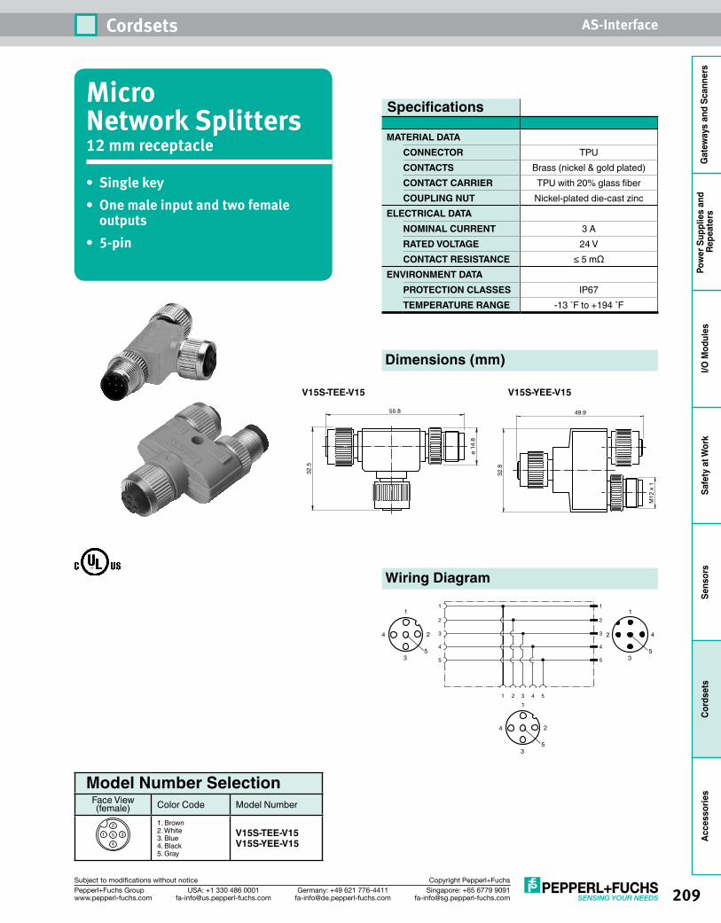
209
Cordsets AS-Interface
Singapore: +65 6779 [email protected]
USA: +1 330 486 [email protected]
Germany: +49 621 [email protected]
Pepperl+Fuchs Groupwww.pepperl-fuchs.com
Subject to modifications without notice Copyright Pepperl+Fuchs
Gat
eway
s an
d Sc
anne
rsPo
wer
Sup
plie
s an
d Re
peat
ers
I/O M
odul
esSa
fety
at W
ork
Sens
ors
Cord
sets
Acce
ssor
ies
Micro Network Splitters12 mm receptacle
• Singlekey• Onemaleinputandtwofemale
outputs• 5-pin
Dimensions (mm)
Model Number Selection Face View (female) Color Code Model Number
1
2
3
4
5
1. Brown2. White3. Blue4. Black5. Gray
V15S-TEE-V15V15S-YEE-V15
Wiring Diagram
Specifications
MATERIAL DATACONNECTOR TPUCONTACTS Brass (nickel & gold plated)CONTACT CARRIER TPU with 20% glass fiberCOUPLING NUT Nickel-plated die-cast zinc
ELECTRICAL DATA NOMINAL CURRENT 3 ARATED VOLTAGE 24 VCONTACT RESISTANCE ≤ 5 mΩ
ENVIRONMENT DATAPROTECTION CLASSES IP67TEMPERATURE RANGE -13 ˚F to +194 ˚F
49.9
32.8
M12
x 1
ø 1
4.8
55.8
32.5
1
1 2 3 4 5
2
3
1
2
4 4
3
5 5
1
2 4
35
1
4
35
2
1
4
35
2
V15S-TEE-V15 V15S-YEE-V15
210
Cordsets AS-Interface
Singapore: +65 6779 [email protected]
USA: +1 330 486 [email protected]
Germany: +49 621 [email protected]
Pepperl+Fuchs Groupwww.pepperl-fuchs.com
Subject to modifications without notice Copyright Pepperl+Fuchs
Gat
eway
s an
d Sc
anne
rsPo
wer
Sup
plie
s an
dRe
peat
ers
I/O M
odul
esSa
fety
at W
ork
Sens
ors
Cord
sets
Acce
ssor
ies
Notes
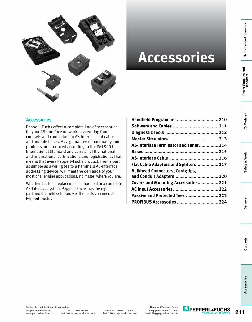
Gat
eway
s an
d Sc
anne
rsPo
wer
Sup
plie
s an
d Re
peat
ers
I/O M
odul
esSa
fety
at W
ork
Sens
ors
Cord
sets
Acce
ssor
ies
211Singapore: +65 6779 [email protected]
USA: +1 330 486 [email protected]
Germany: +49 621 [email protected]
Pepperl+Fuchs Groupwww.pepperl-fuchs.com
Subject to modifications without notice Copyright Pepperl+Fuchs
Accessories
AccessoriesPepperl+Fuchs offers a complete line of accessories for your AS-Interface network—everything from cordsets and connectors to AS-Interface flat cable and module bases. As a guarantee of our quality, our products are produced according to the ISO 9001 International Standard and carry all of the national and international certifications and registrations. That means that every Pepperl+Fuchs product, from a part as simple as a wiring tee to a handheld AS-Interface addressing device, will meet the demands of your most challenging applications, no matter where you are.
Whether it is for a replacement component or a complete AS-Interface system, Pepperl+Fuchs has the right part and the right solution. Get the parts you need at Pepperl+Fuchs.
Handheld Programmer ................................ 210Software and Cables ................................... 211Diagnostic Tools ......................................... 212Master Simulators ....................................... 213AS-Interface Terminator and Tuner ............... 214Bases ......................................................... 215AS-Interface Cable ...................................... 216Flat Cable Adapters and Splitters ................. 217Bulkhead Connectors, Cordgrips, and Conduit Adapters .................................. 220Covers and Mounting Accessories ................ 221AC Input Accessories ................................... 222Passive and Protected Tees ......................... 223PROFIBUS Accessories ................................ 224
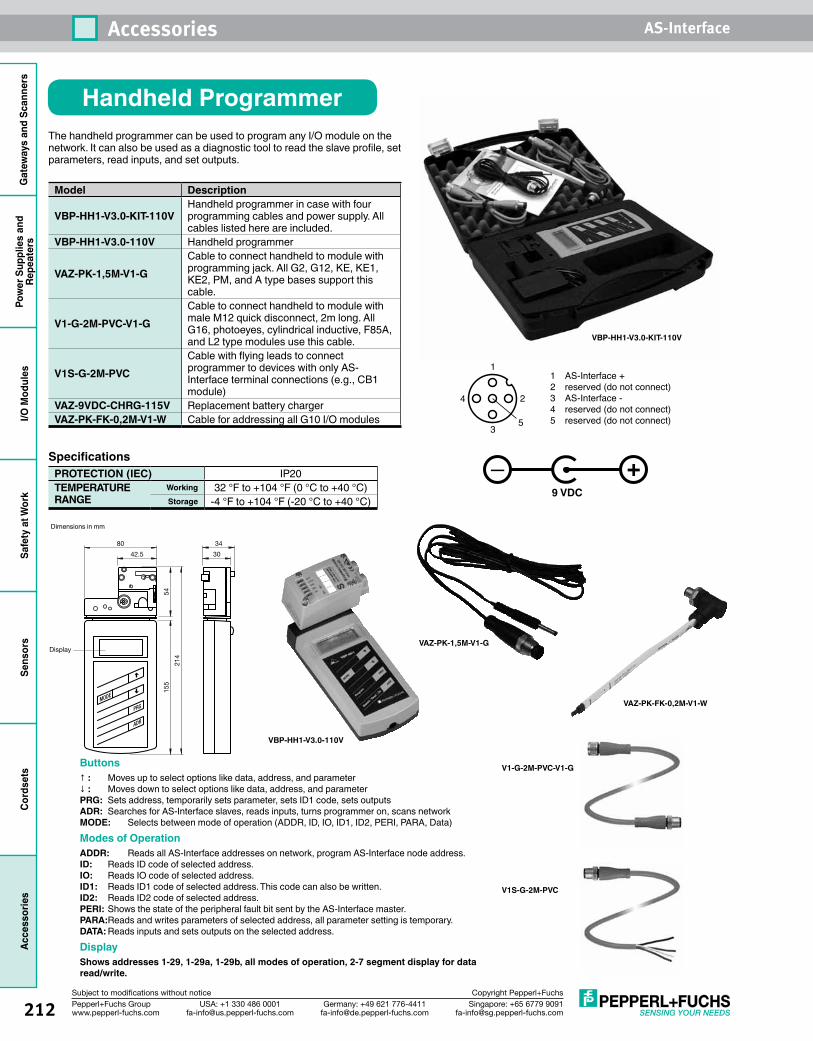
212 Singapore: +65 6779 [email protected]
USA: +1 330 486 [email protected]
Germany: +49 621 [email protected]
Pepperl+Fuchs Groupwww.pepperl-fuchs.com
Subject to modifications without notice Copyright Pepperl+Fuchs
Accessories AS-InterfaceG
atew
ays
and
Scan
ners
Pow
er S
uppl
ies
and
Repe
ater
sI/O
Mod
ules
Safe
ty a
t Wor
kSe
nsor
sCo
rdse
tsAc
cess
orie
s
Handheld Programmer
Specifications PROTECTION (IEC) IP20TEMPERATURE RANGE
Working 32 °F to +104 °F (0 °C to +40 °C)Storage -4 °F to +104 °F (-20 °C to +40 °C)
Model Description
VBP-HH1-V3.0-KIT-110VHandheld programmer in case with four programming cables and power supply. All cables listed here are included.
VBP-HH1-V3.0-110V Handheld programmer
VAZ-PK-1,5M-V1-GCable to connect handheld to module with programming jack. All G2, G12, KE, KE1, KE2, PM, and A type bases support this cable.
V1-G-2M-PVC-V1-GCable to connect handheld to module with male M12 quick disconnect, 2m long. All G16, photoeyes, cylindrical inductive, F85A, and L2 type modules use this cable.
V1S-G-2M-PVCCable with flying leads to connect programmer to devices with only AS-Interface terminal connections (e.g., CB1 module)
VAZ-9VDC-CHRG-115V Replacement battery chargerVAZ-PK-FK-0,2M-V1-W Cable for addressing all G10 I/O modules
The handheld programmer can be used to program any I/O module on the network. It can also be used as a diagnostic tool to read the slave profile, set parameters, read inputs, and set outputs.
Buttons↑ : Moves up to select options like data, address, and parameter↓ : Moves down to select options like data, address, and parameterPRG: Sets address, temporarily sets parameter, sets ID1 code, sets outputsADR: Searches for AS-Interface slaves, reads inputs, turns programmer on, scans networkMODE: Selects between mode of operation (ADDR, ID, IO, ID1, ID2, PERI, PARA, Data)Modes of OperationADDR: Reads all AS-Interface addresses on network, program AS-Interface node address.ID: Reads ID code of selected address.IO: Reads IO code of selected address.ID1: Reads ID1 code of selected address. This code can also be written.ID2: Reads ID2 code of selected address.PERI: Shows the state of the peripheral fault bit sent by the AS-Interface master.PARA: Reads and writes parameters of selected address, all parameter setting is temporary.DATA: Reads inputs and sets outputs on the selected address.DisplayShows addresses 1-29, 1-29a, 1-29b, all modes of operation, 2-7 segment display for data read/write.
30
34
42.5
80
Display
MODE
PRG
ADR
214
155
54
1
4 2
35
1 AS-Interface +2 reserved (do not connect)3 AS-Interface -4 reserved (do not connect)5 reserved (do not connect)
Dimensions in mm
+_
VAZ-PK-1,5M-V1-G
VBP-HH1-V3.0-KIT-110V
VBP-HH1-V3.0-110V
9 VDC
V1-G-2M-PVC-V1-G
V1S-G-2M-PVC
VAZ-PK-FK-0,2M-V1-W
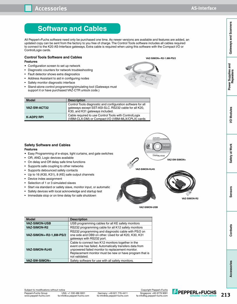
213Singapore: +65 6779 [email protected]
USA: +1 330 486 [email protected]
Germany: +49 621 [email protected]
Pepperl+Fuchs Groupwww.pepperl-fuchs.com
Subject to modifications without notice Copyright Pepperl+Fuchs
Accessories AS-Interface
Gat
eway
s an
d Sc
anne
rsPo
wer
Sup
plie
s an
d Re
peat
ers
I/O M
odul
esSa
fety
at W
ork
Sens
ors
Cord
sets
Acce
ssor
ies
All Pepperl+Fuchs software need only be purchased one time. As newer versions are available and features are added, an updated copy can be sent from the factory to you free of charge. The Control Tools software includes all cables required to connect to the K20 AS-Interface gateways. Extra cable is required when using this software with the Compact I/O or ControlLogix cards.
Model Description
VAZ-SW-ACT32Control Tools diagnostic and configuration software for all gateways except SST-ASI-SLC. RS232 cable for all K20, K30, and K31 gateways included.
K-ADP2 RPI Cable required to use Control Tools with ControlLogix (VBM-CLX-DM) or Compact I/O (VBM-MLX/CPLX) cards
Control Tools Software and CablesFeatures• Configuration screen to set up network• Diagnostic counters for network troubleshooting• Fault detector shows extra diagnostics• Address Assistant to aid in configuring nodes• Safety monitor diagnostic interface• Stand-alone control programming/simulating tool (Gateways must
support it or have purchased VAZ-CTR unlock code.)
Model DescriptionVAZ-SIMON-USB USB programming cables for all KE safety monitorsVAZ-SIMON-R2 RS232 programming cable for all K12 safety monitors
VAZ-SIMON+-R2-1,8M-PS/2RS232 programming and diagnostic cable with PS/2 on one side and DB9 on other. Used for all K20, K30, K31 gateways with RS232 port.
VAZ-SIMON-RJ45
Cable to connect two K12 monitors together in the event one has failed. Automatically transfers data from unpowered failed monitor to replacement monitor. Replacement monitor must be new or have program that is not validated.
VAZ-SW-SIMON+ Safety software for use with all safety monitors.
Safety Software and CablesFeatures• Easy Programming of e-stops, light curtains, and gate switches• OR, AND, Logic devices available• On delay and Off delay safe time functions• Supports safe coupling to other networks• Supports debounced safety contacts• Up to 16 (K30, K31), 8 (KE) safe output channels• Device index assignment• Selection of 1 or 3 simulated slaves• Start via standard or safety slave, monitor input, or automatic• Safety devices with local acknowledge and startup test• Immediate stop or on time delay for safe shutdown
Software and Cables
VAZ-SIMON+-R2-1.8M-PS/2
VAZ-SIMON-R2
VAZ-SW-SIMON+
VAZ-SIMON-RJ45
VAZ-SIMON-USB
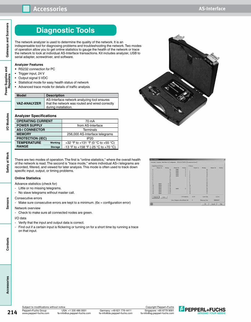
214 Singapore: +65 6779 [email protected]
USA: +1 330 486 [email protected]
Germany: +49 621 [email protected]
Pepperl+Fuchs Groupwww.pepperl-fuchs.com
Subject to modifications without notice Copyright Pepperl+Fuchs
Accessories AS-InterfaceG
atew
ays
and
Scan
ners
Pow
er S
uppl
ies
and
Repe
ater
sI/O
Mod
ules
Safe
ty a
t Wor
kSe
nsor
sCo
rdse
tsAc
cess
orie
s
Diagnostic ToolsThe network analyzer is used to determine the quality of the network. It is an indispensable tool for diagnosing problems and troubleshooting the network. Two modes of operation allow you to get online statistics to gauge the health of the network or trace the network to look at individual AS-Interface transactions. Kit includes analyzer, USB to serial adapter, screwdriver, and software.
Analyzer Features• RS232 connection for PC• Trigger input, 24 V• Output signal 5 VDC• Statistical mode for easy health status of network• Advanced trace mode for details of traffic analysis
Analyzer Specifications OPERATING CURRENT 70 mAPOWER SUPPLY from AS-InterfaceAS-i CONNECTOR TerminalsMEMORY 256,000 AS-Interface telegramsPROTECTION (IEC) IP20TEMPERATURE RANGE
Working +32 °F to +131 °F (0 °C to +55 °C)Storage -13 °F to +158 °F (-25 °C to +70 °C)
Model Description
VAZ-ANALYZERAS-Interface network analyzing tool ensures that the network was routed and wired correctly during installation.
There are two modes of operation. The first is "online statistics," where the overall health of the network is read. The second is "trace mode," where individual AS-i telegrams are recorded, filtered, and viewed for later analysis. This mode is often used to track down specific input, output, or timing problems.
Online StatisticsAdvance statistics (check for)- Little or no missing telegrams.- No slave telegrams without master call.Consecutive errors- Make sure consecutive errors are kept to a minimum. (6x = configuration error)Network overview- Check to make sure all connected nodes are green.I/O data- Verify that the input and output data is correct.- Find out if a certain input is flickering or turning on for a short time by running a trace
on that input.
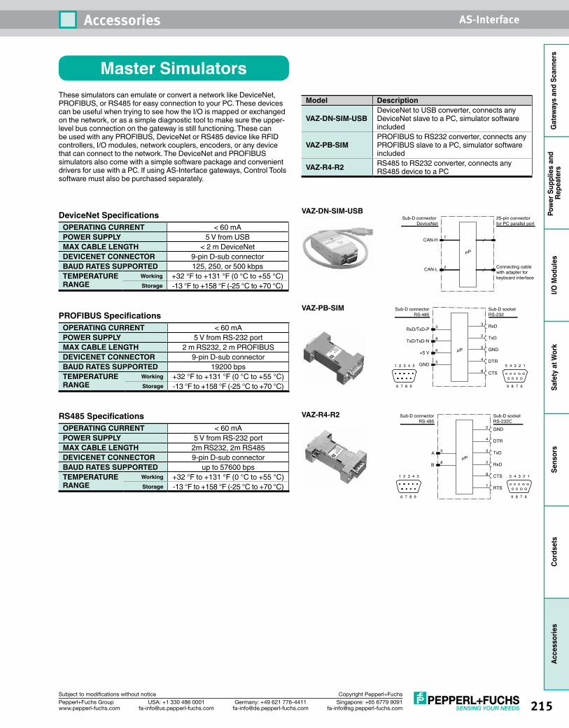
215Singapore: +65 6779 [email protected]
USA: +1 330 486 [email protected]
Germany: +49 621 [email protected]
Pepperl+Fuchs Groupwww.pepperl-fuchs.com
Subject to modifications without notice Copyright Pepperl+Fuchs
Accessories AS-Interface
Gat
eway
s an
d Sc
anne
rsPo
wer
Sup
plie
s an
d Re
peat
ers
I/O M
odul
esSa
fety
at W
ork
Sens
ors
Cord
sets
Acce
ssor
ies
Master SimulatorsModel Description
VAZ-DN-SIM-USBDeviceNet to USB converter, connects any DeviceNet slave to a PC, simulator software included
VAZ-PB-SIMPROFIBUS to RS232 converter, connects any PROFIBUS slave to a PC, simulator software included
VAZ-R4-R2 RS485 to RS232 converter, connects any RS485 device to a PC
These simulators can emulate or convert a network like DeviceNet, PROFIBUS, or RS485 for easy connection to your PC. These devices can be useful when trying to see how the I/O is mapped or exchanged on the network, or as a simple diagnostic tool to make sure the upper- level bus connection on the gateway is still functioning. These can be used with any PROFIBUS, DeviceNet or RS485 device like RFID controllers, I/O modules, network couplers, encoders, or any device that can connect to the network. The DeviceNet and PROFIBUS simulators also come with a simple software package and convenient drivers for use with a PC. If using AS-Interface gateways, Control Tools software must also be purchased separately.
DeviceNet Specifications OPERATING CURRENT < 60 mAPOWER SUPPLY 5 V from USBMAX CABLE LENGTH < 2 m DeviceNetDEVICENET CONNECTOR 9-pin D-sub connectorBAUD RATES SUPPORTED 125, 250, or 500 kbpsTEMPERATURE RANGE
Working +32 °F to +131 °F (0 °C to +55 °C)Storage -13 °F to +158 °F (-25 °C to +70 °C)
PROFIBUS Specifications OPERATING CURRENT < 60 mAPOWER SUPPLY 5 V from RS-232 portMAX CABLE LENGTH 2 m RS232, 2 m PROFIBUSDEVICENET CONNECTOR 9-pin D-sub connectorBAUD RATES SUPPORTED 19200 bpsTEMPERATURE RANGE
Working +32 °F to +131 °F (0 °C to +55 °C)Storage -13 °F to +158 °F (-25 °C to +70 °C)
RS485 Specifications OPERATING CURRENT < 60 mAPOWER SUPPLY 5 V from RS-232 portMAX CABLE LENGTH 2m RS232, 2m RS485DEVICENET CONNECTOR 9-pin D-sub connectorBAUD RATES SUPPORTED up to 57600 bpsTEMPERATURE RANGE
Working +32 °F to +131 °F (0 °C to +55 °C)Storage -13 °F to +158 °F (-25 °C to +70 °C)
25-pin connectorfor PC parallel port
Connecting cable with adapter for keyboard interface
Sub-D connector DeviceNet
µP
CAN-H
CAN-L
7
2
Sub-D socket RS-232C
Sub-D connector RS-485
µP
GND
DTR
TxD
RxD
CTS
RTS
A
B
5
4
3
2
8
7
3
8
1 2 3 4 5
6 7 8 9
5 4 3 2 1
9 8 7 6
Sub-D socket RS-232
Sub-D connector RS-485
µP
RxD
TxD
GND
DTR
CTS
RxD/TxD-P
TxD/TxD-N
+5 V
GND
3
2
5
4
8
3
8
6
51 2 3 4 5
6 7 8 9
5 4 3 2 1
9 8 7 6
VAZ-DN-SIM-USB
VAZ-PB-SIM
VAZ-R4-R2
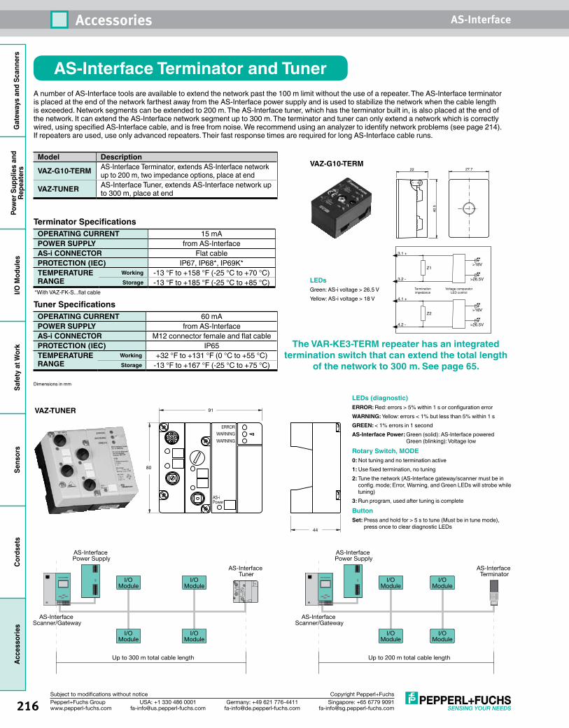
216 Singapore: +65 6779 [email protected]
USA: +1 330 486 [email protected]
Germany: +49 621 [email protected]
Pepperl+Fuchs Groupwww.pepperl-fuchs.com
Subject to modifications without notice Copyright Pepperl+Fuchs
Accessories AS-InterfaceG
atew
ays
and
Scan
ners
Pow
er S
uppl
ies
and
Repe
ater
sI/O
Mod
ules
Safe
ty a
t Wor
kSe
nsor
sCo
rdse
tsAc
cess
orie
s
AS-Interface Terminator and TunerA number of AS-Interface tools are available to extend the network past the 100 m limit without the use of a repeater. The AS-Interface terminator is placed at the end of the network farthest away from the AS-Interface power supply and is used to stabilize the network when the cable length is exceeded. Network segments can be extended to 200 m. The AS-Interface tuner, which has the terminator built in, is also placed at the end of the network. It can extend the AS-Interface network segment up to 300 m. The terminator and tuner can only extend a network which is correctly wired, using specified AS-Interface cable, and is free from noise. We recommend using an analyzer to identify network problems (see page 214). If repeaters are used, use only advanced repeaters. Their fast response times are required for long AS-Interface cable runs.
Model Description
VAZ-G10-TERM AS-Interface Terminator, extends AS-Interface network up to 200 m, two impedance options, place at end
VAZ-TUNER AS-Interface Tuner, extends AS-Interface network up to 300 m, place at end
Terminator Specifications OPERATING CURRENT 15 mAPOWER SUPPLY from AS-InterfaceAS-i CONNECTOR Flat cablePROTECTION (IEC) IP67, IP68*, IP69K*TEMPERATURE RANGE
Working -13 °F to +158 °F (-25 °C to +70 °C)Storage -13 °F to +185 °F (-25 °C to +85 °C)
VAZ-G10-TERM
40.5
22 27.7
80
91
ERROR
WARNING
WARNING
AS-iPower
44
VAZ-TUNER
I/OModule
I/OModule
I/OModule
I/OModule
AS-Interface Power Supply
AS-Interface Scanner/Gateway
AS-Interface Terminator
Up to 200 m total cable length
I/OModule
I/OModule
I/OModule
I/OModule
AS-Interface Power Supply
AS-Interface Scanner/Gateway
AS-Interface Tuner
Up to 300 m total cable length
LEDs (diagnostic)ERROR: Red: errors > 5% within 1 s or configuration errorWARNING: Yellow: errors < 1% but less than 5% within 1 sGREEN: < 1% errors in 1 secondAS-Interface Power: Green (solid): AS-Interface powered
Green (blinking): Voltage low
Rotary Switch, MODE0: Not tuning and no termination active1: Use fixed termination, no tuning2: Tune the network (AS-Interface gateway/scanner must be in
config. mode; Error, Warning, and Green LEDs will strobe while tuning)
3: Run program, used after tuning is complete
ButtonSet: Press and hold for > 5 s to tune (Must be in tune mode),
press once to clear diagnostic LEDs
Tuner Specifications OPERATING CURRENT 60 mAPOWER SUPPLY from AS-InterfaceAS-i CONNECTOR M12 connector female and flat cablePROTECTION (IEC) IP65TEMPERATURE RANGE
Working +32 °F to +131 °F (0 °C to +55 °C)Storage -13 °F to +167 °F (-25 °C to +75 °C)
LEDsGreen: AS-i voltage > 26.5 VYellow: AS-i voltage > 18 V
The VAR-KE3-TERM repeater has an integrated termination switch that can extend the total length
of the network to 300 m. See page 65.Dimensions in mm
*With VAZ-FK-S...flat cableVoltage comparator
LED controlTerminationimpedance
3.1 +
3.2 -
Z1>18V
>26.5V
4.1 +
4.2 -
Z2>18V
>26.5V
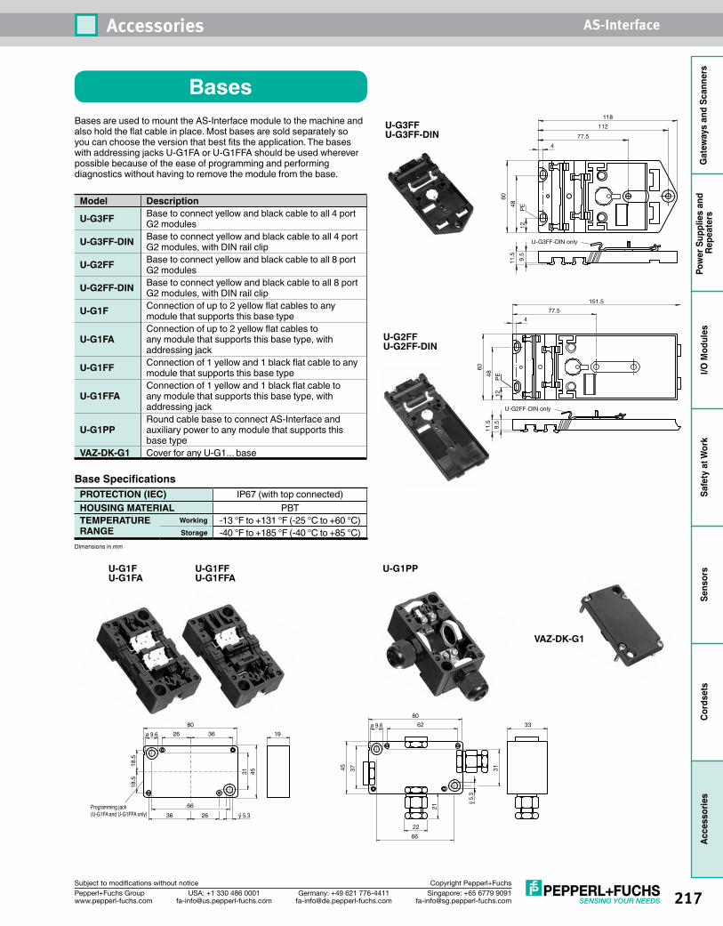
217Singapore: +65 6779 [email protected]
USA: +1 330 486 [email protected]
Germany: +49 621 [email protected]
Pepperl+Fuchs Groupwww.pepperl-fuchs.com
Subject to modifications without notice Copyright Pepperl+Fuchs
Accessories AS-Interface
Gat
eway
s an
d Sc
anne
rsPo
wer
Sup
plie
s an
d Re
peat
ers
I/O M
odul
esSa
fety
at W
ork
Sens
ors
Cord
sets
Acce
ssor
ies
BasesBases are used to mount the AS-Interface module to the machine and also hold the flat cable in place. Most bases are sold separately so you can choose the version that best fits the application. The bases with addressing jacks U-G1FA or U-G1FFA should be used wherever possible because of the ease of programming and performing diagnostics without having to remove the module from the base.
Model Description
U-G3FF Base to connect yellow and black cable to all 4 port G2 modules
U-G3FF-DIN Base to connect yellow and black cable to all 4 port G2 modules, with DIN rail clip
U-G2FF Base to connect yellow and black cable to all 8 port G2 modules
U-G2FF-DIN Base to connect yellow and black cable to all 8 port G2 modules, with DIN rail clip
U-G1F Connection of up to 2 yellow flat cables to any module that supports this base type
U-G1FAConnection of up to 2 yellow flat cables to any module that supports this base type, with addressing jack
U-G1FF Connection of 1 yellow and 1 black flat cable to any module that supports this base type
U-G1FFAConnection of 1 yellow and 1 black flat cable to any module that supports this base type, with addressing jack
U-G1PPRound cable base to connect AS-Interface and auxiliary power to any module that supports this base type
VAZ-DK-G1 Cover for any U-G1... base
Base SpecificationsPROTECTION (IEC) IP67 (with top connected)HOUSING MATERIAL PBTTEMPERATURE RANGE
Working -13 °F to +131 °F (-25 °C to +60 °C)Storage -40 °F to +185 °F (-40 °C to +85 °C)
U-G3FFU-G3FF-DIN 77.5
U-G3FF-DIN only
60
118
12
48
PE
4
112
11.5
9.5
U-G2FFU-G2FF-DIN
U-G1FU-G1FA
ÿ 5.3
ø 9.6
18.5
18.5
66
31
80
Programming jack(U-G1FA and U-G1FFA only)
3626
2636
45
19
U-G1FFU-G1FFA
U-G1PP
37
ÿ 5.
3
22
21
45
80
62 33ø 9.6
66
31
VAZ-DK-G1
Dimensions in mm
77.5
151.5
60
12
48
PE
4
11.5
9.5
U-G2FF-DIN only
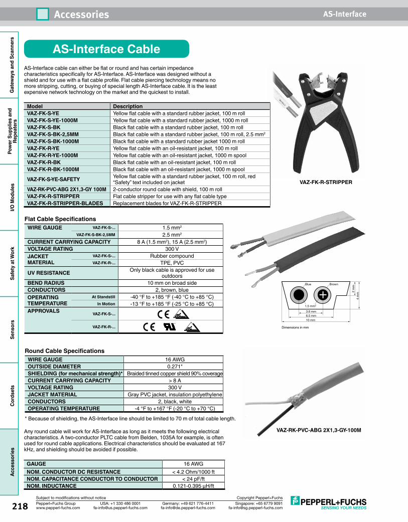
218 Singapore: +65 6779 [email protected]
USA: +1 330 486 [email protected]
Germany: +49 621 [email protected]
Pepperl+Fuchs Groupwww.pepperl-fuchs.com
Subject to modifications without notice Copyright Pepperl+Fuchs
Accessories AS-InterfaceG
atew
ays
and
Scan
ners
Pow
er S
uppl
ies
and
Repe
ater
sI/O
Mod
ules
Safe
ty a
t Wor
kSe
nsor
sCo
rdse
tsAc
cess
orie
s
AS-Interface CableAS-Interface cable can either be flat or round and has certain impedance characteristics specifically for AS-Interface. AS-Interface was designed without a shield and for use with a flat cable profile. Flat cable piercing technology means no more stripping, cutting, or buying of special length AS-Interface cable. It is the least expensive network technology on the market and the quickest to install.
Round Cable Specifications WIRE GAUGE 16 AWGOUTSIDE DIAMETER 0.271"SHIELDING (for mechanical strength)* Braided tinned copper shield 90% coverageCURRENT CARRYING CAPACITY > 8 AVOLTAGE RATING 300 VJACKET MATERIAL Gray PVC jacket, insulation polyethyleneCONDUCTORS 2, black, whiteOPERATING TEMPERATURE -4 °F to +167 °F (-20 °C to +70 °C)
* Because of shielding, the AS-Interface line should be limited to 70 m of total cable length.
Blue
1.5 mm2
3.6 mm6.5 mm
2 m
m4
mm
10 mm
Brown
VAZ-RK-PVC-ABG 2X1,3-GY-100M
VAZ-FK-R-STRIPPER
Model DescriptionVAZ-FK-S-YE Yellow flat cable with a standard rubber jacket, 100 m rollVAZ-FK-S-YE-1000M Yellow flat cable with a standard rubber jacket, 1000 m rollVAZ-FK-S-BK Black flat cable with a standard rubber jacket, 100 m rollVAZ-FK-S-BK-2,5MM Black flat cable with a standard rubber jacket, 100 m roll, 2.5 mm2
VAZ-FK-S-BK-1000M Black flat cable with a standard rubber jacket 1000 m rollVAZ-FK-R-YE Yellow flat cable with an oil-resistant jacket, 100 m rollVAZ-FK-R-YE-1000M Yellow flat cable with an oil-resistant jacket, 1000 m spoolVAZ-FK-R-BK Black flat cable with an oil-resistant jacket, 100 m rollVAZ-FK-R-BK-1000M Black flat cable with an oil-resistant jacket, 1000 m spool
VAZ-FK-S-YE-SAFETY Yellow flat cable with a standard rubber jacket, 100 m roll, red “Safety” text included on jacket
VAZ-RK-PVC-ABG 2X1,3-GY 100M 2-conductor round cable with shield, 100 m rollVAZ-FK-R-STRIPPER Flat cable stripper for use with any flat cable typeVAZ-FK-R-STRIPPER-BLADES Replacement blades for VAZ-FK-R-STRIPPER
Flat Cable Specifications WIRE GAUGE VAZ-FK-S-... 1.5 mm2
VAZ-FK-S-BK-2,5MM 2.5 mm2
CURRENT CARRYING CAPACITY 8 A (1.5 mm2), 15 A (2.5 mm2)VOLTAGE RATING 300 VJACKET MATERIAL
VAZ-FK-S-... Rubber compoundVAZ-FK-R-... TPE, PVC
UV RESISTANCE Only black cable is approved for use outdoors
BEND RADIUS 10 mm on broad sideCONDUCTORS 2, brown, blueOPERATING TEMPERATURE
At Standstill -40 °F to +185 °F (-40 °C to +85 °C)In Motion -13 °F to +185 °F (-25 °C to +85 °C)
APPROVALS VAZ-FK-S-...
VAZ-FK-R-...
Any round cable will work for AS-Interface as long as it meets the following electrical characteristics. A two-conductor PLTC cable from Belden, 1035A for example, is often used for round cable applications. Electrical characteristics should be evaluated at 167 kHz, and shielding should be avoided if possible.
GAUGE 16 AWGNOM. CONDUCTOR DC RESISTANCE < 4.2 Ohm/1000 ftNOM. CAPACITANCE CONDUCTOR TO CONDUCTOR < 24 pF/ftNOM. INDUCTANCE 0.121-0.395 µH/ft
Dimensions in mm
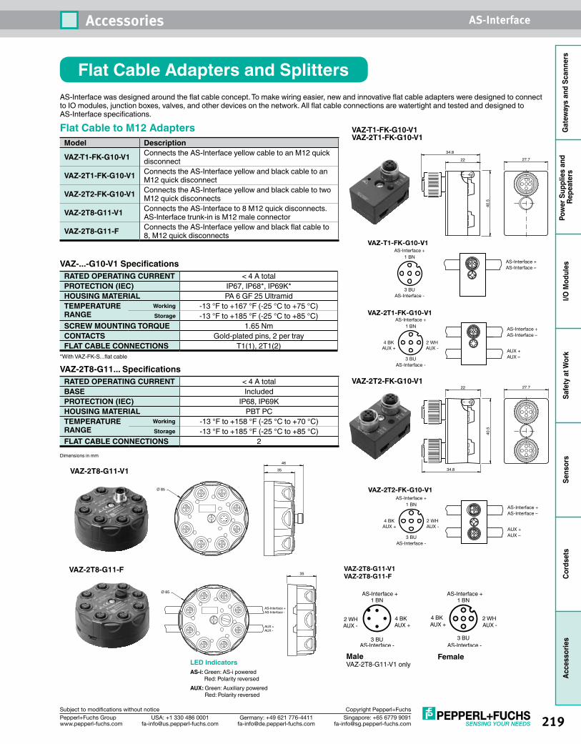
219Singapore: +65 6779 [email protected]
USA: +1 330 486 [email protected]
Germany: +49 621 [email protected]
Pepperl+Fuchs Groupwww.pepperl-fuchs.com
Subject to modifications without notice Copyright Pepperl+Fuchs
Accessories AS-Interface
Gat
eway
s an
d Sc
anne
rsPo
wer
Sup
plie
s an
d Re
peat
ers
I/O M
odul
esSa
fety
at W
ork
Sens
ors
Cord
sets
Acce
ssor
ies
Flat Cable Adapters and SplittersAS-Interface was designed around the flat cable concept. To make wiring easier, new and innovative flat cable adapters were designed to connect to IO modules, junction boxes, valves, and other devices on the network. All flat cable connections are watertight and tested and designed to AS-Interface specifications.
Flat Cable to M12 AdaptersModel Description
VAZ-T1-FK-G10-V1 Connects the AS-Interface yellow cable to an M12 quick disconnect
VAZ-2T1-FK-G10-V1 Connects the AS-Interface yellow and black cable to an M12 quick disconnect
VAZ-2T2-FK-G10-V1 Connects the AS-Interface yellow and black cable to two M12 quick disconnects
VAZ-2T8-G11-V1 Connects the AS-Interface to 8 M12 quick disconnects. AS-Interface trunk-in is M12 male connector
VAZ-2T8-G11-F Connects the AS-Interface yellow and black flat cable to 8, M12 quick disconnects
VAZ-...-G10-V1 Specifications RATED OPERATING CURRENT < 4 A totalPROTECTION (IEC) IP67, IP68*, IP69K*HOUSING MATERIAL PA 6 GF 25 UltramidTEMPERATURE RANGE
Working -13 °F to +167 °F (-25 °C to +75 °C)Storage -13 °F to +185 °F (-25 °C to +85 °C)
SCREW MOUNTING TORQUE 1.65 NmCONTACTS Gold-plated pins, 2 per trayFLAT CABLE CONNECTIONS T1(1), 2T1(2)
*With VAZ-FK-S...flat cable
VAZ-2T8-G11... Specifications RATED OPERATING CURRENT < 4 A totalBASE IncludedPROTECTION (IEC) IP68, IP69KHOUSING MATERIAL PBT PCTEMPERATURE RANGE
Working -13 °F to +158 °F (-25 °C to +70 °C)Storage -13 °F to +185 °F (-25 °C to +85 °C)
FLAT CABLE CONNECTIONS 2
VAZ-T1-FK-G10-V1VAZ-2T1-FK-G10-V1
Dimensions in mm
40.5
22 27.7
34.8
40.5
22 27.7
34.8
VAZ-2T2-FK-G10-V1
VAZ-2T1-FK-G10-V1
1 BN
4 BK 2 WH
3 BU
AS-Interface +
AS-Interface -
AS-Interface +AS-Interface –
AUX +AUX –
AUX -AUX +
1 BN
3 BU
AS-Interface +
VAZ-T1-FK-G10-V1
AS-Interface -
AS-Interface +AS-Interface –
VAZ-2T2-FK-G10-V1
1 BN
4 BK 2 WH
3 BU
AS-Interface +
AS-Interface -
AS-Interface +AS-Interface –
AUX +AUX –
AUX -AUX +
VAZ-2T8-G11-F35
Ø 85
AS-Interface +AS-Interface -
AUX +AUX -
VAZ-2T8-G11-V1 35
46
Ø 85
LED IndicatorsAS-i: Green: AS-i powered
Red: Polarity reversedAUX: Green: Auxiliary powered
Red: Polarity reversed
3 BU
4 BK2 WH
1 BN
3 BU
2 WH4 BK
1 BNAS-Interface +
AS-Interface -
AUX + AUX +AUX - AUX -
AS-Interface +
AS-Interface -
MaleVAZ-2T8-G11-V1 only
Female
VAZ-2T8-G11-V1VAZ-2T8-G11-F
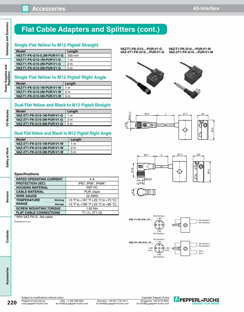
220 Singapore: +65 6779 [email protected]
USA: +1 330 486 [email protected]
Germany: +49 621 [email protected]
Pepperl+Fuchs Groupwww.pepperl-fuchs.com
Subject to modifications without notice Copyright Pepperl+Fuchs
Accessories AS-InterfaceG
atew
ays
and
Scan
ners
Pow
er S
uppl
ies
and
Repe
ater
sI/O
Mod
ules
Safe
ty a
t Wor
kSe
nsor
sCo
rdse
tsAc
cess
orie
s
Single Flat Yellow to M12 Pigtail StraightModel LengthVAZ-T1-FK-G10-0,3M-PUR-V1-G 300 mmVAZ-T1-FK-G10-1M-PUR-V1-G 1 mVAZ-T1-FK-G10-2M-PUR-V1-G 2 mVAZ-T1-FK-G10-5M-PUR-V1-G 5 m
Single Flat Yellow to M12 Pigtail Right AngleModel LengthVAZ-T1-FK-G10-1M-PUR-V1-W 1 mVAZ-T1-FK-G10-2M-PUR-V1-W 2 mVAZ-T1-FK-G10-5M-PUR-V1-W 5 m
Dual Flat Yellow and Black to M12 Pigtail StraightModel LengthVAZ-2T1-FK-G10-1M-PUR-V1-G 1 mVAZ-2T1-FK-G10-2M-PUR-V1-G 2 mVAZ-2T1-FK-G10-5M-PUR-V1-G 5 m
Dual Flat Yellow and Black to M12 Pigtail Right AngleModel LengthVAZ-2T1-FK-G10-1M-PUR-V1-W 1 mVAZ-2T1-FK-G10-2M-PUR-V1-W 2 mVAZ-2T1-FK-G10-5M-PUR-V1-W 5 m
Specifications RATED OPERATING CURRENT 4 APROTECTION (IEC) IP67, IP68*, IP69K*HOUSING MATERIAL PBT PCCABLE MATERIAL PUR, blackWIRE GAUGE 22 AWGTEMPERATURE RANGE
Working -13 °F to +167 °F (-25 °C to +75 °C)Storage -13 °F to +185 °F (-25 °C to +85 °C)
SCREW MOUNTING TORQUE 1.65 NmFLAT CABLE CONNECTIONS T1 (1), 2T1 (2)
* With VAZ-FK-S...flat cable
27.7 22
40.5
L45.3
M12
x 1
14.8
VAZ-T1-FK-G10...-PUR-V1-GVAZ-2T1-FK-G10...-PUR-V1-G
VAZ-T1-FK-G10...-PUR-V1-WVAZ-2T1-FK-G10...-PUR-V1-W
Flat Cable Adapters and Splitters (cont.)
Dimensions in mm
27.7 22
40.527.8
14.8
14.2
M12x1
35.1 L
1 BN
3 BU
AS-Interface +
VAZ-T1-FK-G10...V1...
VAZ-2T1-FK-G10...V1...
AS-Interface -
AS-Interface +AS-Interface –
1 BN
4 BK 2 WH
3 BU
AS-Interface +
AS-Interface -
AS-Interface +AS-Interface –
AUX +AUX –
AUX -AUX +
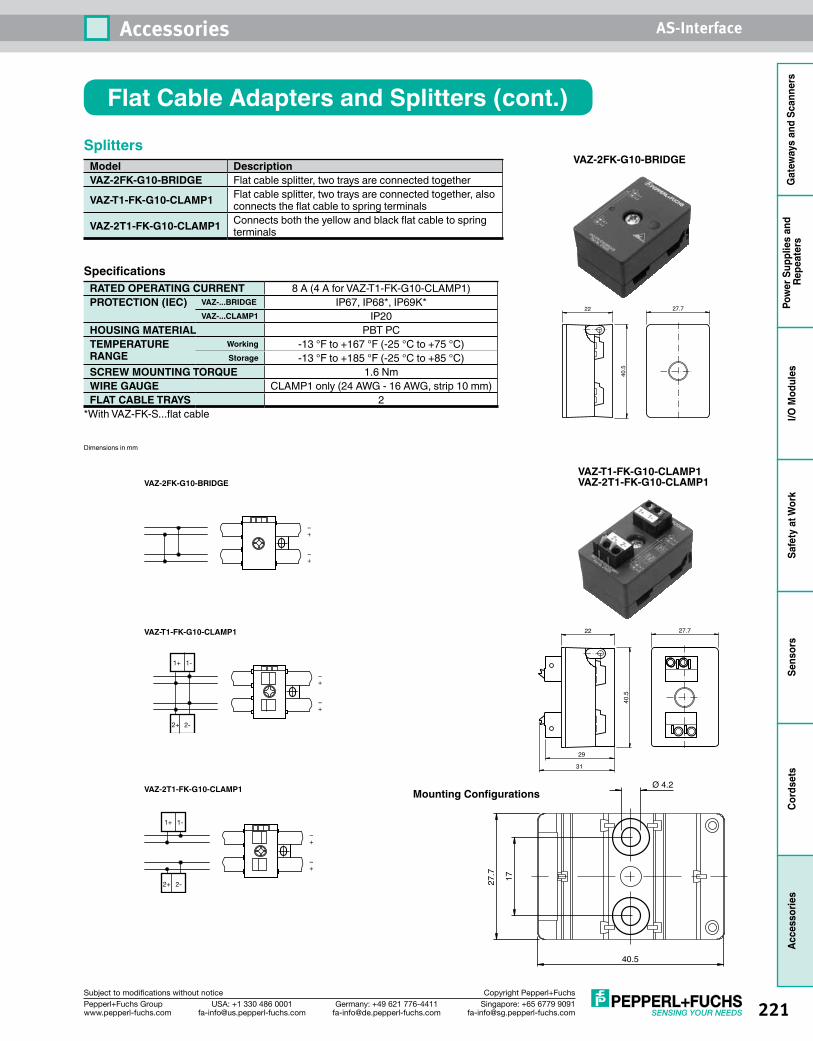
221Singapore: +65 6779 [email protected]
USA: +1 330 486 [email protected]
Germany: +49 621 [email protected]
Pepperl+Fuchs Groupwww.pepperl-fuchs.com
Subject to modifications without notice Copyright Pepperl+Fuchs
Accessories AS-Interface
Gat
eway
s an
d Sc
anne
rsPo
wer
Sup
plie
s an
d Re
peat
ers
I/O M
odul
esSa
fety
at W
ork
Sens
ors
Cord
sets
Acce
ssor
ies
SplittersModel DescriptionVAZ-2FK-G10-BRIDGE Flat cable splitter, two trays are connected together
VAZ-T1-FK-G10-CLAMP1 Flat cable splitter, two trays are connected together, also connects the flat cable to spring terminals
VAZ-2T1-FK-G10-CLAMP1 Connects both the yellow and black flat cable to spring terminals
Specifications RATED OPERATING CURRENT 8 A (4 A for VAZ-T1-FK-G10-CLAMP1)PROTECTION (IEC) VAZ-...BRIDGE IP67, IP68*, IP69K*
VAZ-...CLAMP1 IP20HOUSING MATERIAL PBT PCTEMPERATURE RANGE
Working -13 °F to +167 °F (-25 °C to +75 °C)Storage -13 °F to +185 °F (-25 °C to +85 °C)
SCREW MOUNTING TORQUE 1.6 NmWIRE GAUGE CLAMP1 only (24 AWG - 16 AWG, strip 10 mm)FLAT CABLE TRAYS 2
*With VAZ-FK-S...flat cable
VAZ-2FK-G10-BRIDGE
40.5
22 27.7
VAZ-T1-FK-G10-CLAMP1
1+ 1-
2+ 2-
–+
–+
1+ 1-
2+ 2-
–+
–+
–+
–+
VAZ-2FK-G10-BRIDGE
VAZ-2T1-FK-G10-CLAMP1
VAZ-T1-FK-G10-CLAMP1VAZ-2T1-FK-G10-CLAMP1
Flat Cable Adapters and Splitters (cont.)
Dimensions in mm
1727.7
40.5
Ø 4.2
40.5
22 27.7
29
31
Mounting Configurations
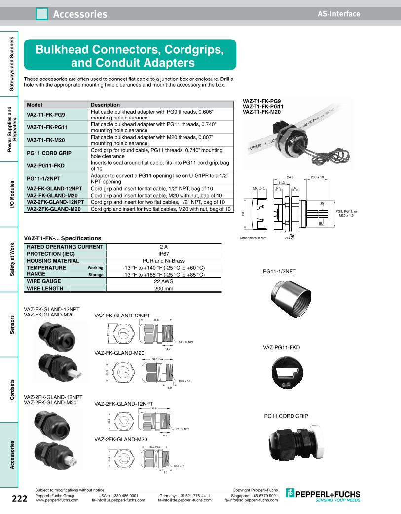
222 Singapore: +65 6779 [email protected]
USA: +1 330 486 [email protected]
Germany: +49 621 [email protected]
Pepperl+Fuchs Groupwww.pepperl-fuchs.com
Subject to modifications without notice Copyright Pepperl+Fuchs
Accessories AS-InterfaceG
atew
ays
and
Scan
ners
Pow
er S
uppl
ies
and
Repe
ater
sI/O
Mod
ules
Safe
ty a
t Wor
kSe
nsor
sCo
rdse
tsAc
cess
orie
s
Bulkhead Connectors, Cordgrips, and Conduit Adapters
These accessories are often used to connect flat cable to a junction box or enclosure. Drill a hole with the appropriate mounting hole clearances and mount the accessory in the box.
Model Description
VAZ-T1-FK-PG9 Flat cable bulkhead adapter with PG9 threads, 0.606" mounting hole clearance
VAZ-T1-FK-PG11 Flat cable bulkhead adapter with PG11 threads, 0.740" mounting hole clearance
VAZ-T1-FK-M20 Flat cable bulkhead adapter with M20 threads, 0.807" mounting hole clearance
PG11 CORD GRIP Cord grip for round cable, PG11 threads, 0.740” mounting hole clearance
VAZ-PG11-FKD Inserts to seal around flat cable, fits into PG11 cord grip, bag of 10
PG11-1/2NPT Adapter to convert a PG11 opening like on U-G1PP to a 1/2” NPT opening
VAZ-FK-GLAND-12NPT Cord grip and insert for flat cable, 1/2" NPT, bag of 10VAZ-FK-GLAND-M20 Cord grip and insert for flat cable, M20 with nut, bag of 10VAZ-2FK-GLAND-12NPT Cord grip and insert for two flat cables, 1/2" NPT, bag of 10VAZ-2FK-GLAND-M20 Cord grip and insert for two flat cables, M20 with nut, bag of 10
VAZ-T1-FK-... Specifications RATED OPERATING CURRENT 2 APROTECTION (IEC) IP67HOUSING MATERIAL PUR and Ni-BrassTEMPERATURE RANGE
Working -13 °F to +140 °F (-25 °C to +60 °C)Storage -13 °F to +185 °F (-25 °C to +85 °C)
WIRE GAUGE 22 AWGWIRE LENGTH 200 mm
VAZ-T1-FK-PG9VAZ-T1-FK-PG11VAZ-T1-FK-M20
24
PG9, PG11, orM20 x 1.5
4.5 6.5
24.5 200 ± 10
611.3
6.5
23
BN
BU
PG11 CORD GRIP
VAZ-PG11-FKD
PG11-1/2NPT
Dimensions in mm
VAZ-2FK-GLAND-12NPTVAZ-2FK-GLAND-M20
VAZ-FK-GLAND-12NPTVAZ-FK-GLAND-M20
1/2 - 14 NPT
14.7
45.8
26.8
M20 x 1.5
36.0 max
8.0
24.0
VAZ-FK-GLAND-12NPT
VAZ-FK-GLAND-M20
VAZ-2FK-GLAND-12NPT
VAZ-2FK-GLAND-M20
1/2 - 14 NPT
14.7
45.8
26.8
M20 x 1.5
36.0 max
8.0
24.0
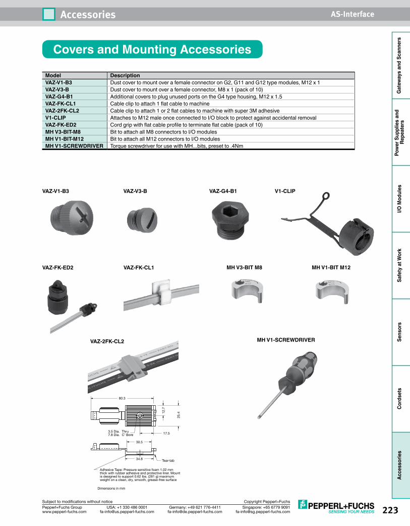
223Singapore: +65 6779 [email protected]
USA: +1 330 486 [email protected]
Germany: +49 621 [email protected]
Pepperl+Fuchs Groupwww.pepperl-fuchs.com
Subject to modifications without notice Copyright Pepperl+Fuchs
Accessories AS-Interface
Gat
eway
s an
d Sc
anne
rsPo
wer
Sup
plie
s an
d Re
peat
ers
I/O M
odul
esSa
fety
at W
ork
Sens
ors
Cord
sets
Acce
ssor
ies
Covers and Mounting Accessories
Model DescriptionVAZ-V1-B3 Dust cover to mount over a female connector on G2, G11 and G12 type modules, M12 x 1VAZ-V3-B Dust cover to mount over a female connector, M8 x 1 (pack of 10)VAZ-G4-B1 Additional covers to plug unused ports on the G4 type housing, M12 x 1.5VAZ-FK-CL1 Cable clip to attach 1 flat cable to machineVAZ-2FK-CL2 Cable clip to attach 1 or 2 flat cables to machine with super 3M adhesiveV1-CLIP Attaches to M12 male once connected to I/O block to protect against accidental removalVAZ-FK-ED2 Cord grip with flat cable profile to terminate flat cable (pack of 10)MH V3-BIT-M8 Bit to attach all M8 connectors to I/O modulesMH V1-BIT-M12 Bit to attach all M12 connectors to I/O modulesMH V1-SCREWDRIVER Torque screwdriver for use with MH...bits, preset to .4Nm
VAZ-V1-B3 VAZ-V3-B VAZ-G4-B1
VAZ-FK-ED2 VAZ-FK-CL1
VAZ-2FK-CL2
V1-CLIP
80.3
30.5
34.8 Tear-tab
17.5ThruC’ Bore
3.5 Dia.7.8 Dia.
12.7
25.4
Adhesive Tape: Pressure sensitive foam 1.02 mm thick with rubber adhesive and protective liner. Mount is designed to support 0.62 lbs. (281 g) maximum weight on a clean, dry, smooth, grease-free surface
Dimensionsinmm
MH V3-BIT M8 MH V1-BIT M12
MH V1-SCREWDRIVER
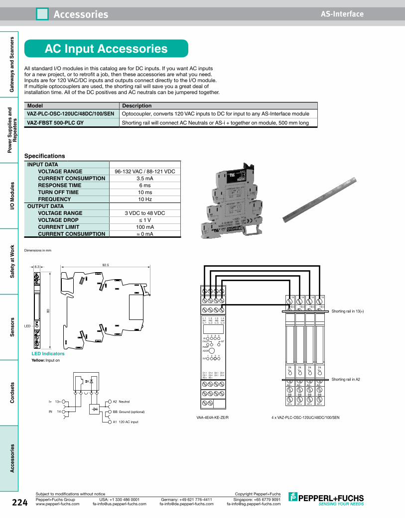
224 Singapore: +65 6779 [email protected]
USA: +1 330 486 [email protected]
Germany: +49 621 [email protected]
Pepperl+Fuchs Groupwww.pepperl-fuchs.com
Subject to modifications without notice Copyright Pepperl+Fuchs
Accessories AS-InterfaceG
atew
ays
and
Scan
ners
Pow
er S
uppl
ies
and
Repe
ater
sI/O
Mod
ules
Safe
ty a
t Wor
kSe
nsor
sCo
rdse
tsAc
cess
orie
s
AC Input AccessoriesAllstandardI/OmodulesinthiscatalogareforDCinputs.IfyouwantACinputsforanewproject,ortoretrofitajob,thentheseaccessoriesarewhatyouneed.Inputsarefor120VAC/DCinputsandoutputsconnectdirectlytotheI/Omodule.Ifmultipleoptocouplersareused,theshortingrailwillsaveyouagreatdealofinstallationtime.AlloftheDCpositivesandACneutralscanbejumperedtogether.
Model DescriptionVAZ-PLC-OSC-120UC/48DC/100/SEN Optocoupler, converts 120 VAC inputs to DC for input to any AS-Interface moduleVAZ-FBST 500-PLC GY Shorting rail will connect AC Neutrals or AS-i + together on module, 500 mm long
Specifications INPUT DATA
VOLTAGE RANGE 96-132 VAC / 88-121 VDCCURRENT CONSUMPTION 3.5 mARESPONSE TIME 6 msTURN OFF TIME 10 msFREQUENCY 10 Hz
OUTPUT DATAVOLTAGE RANGE 3 VDC to 48 VDCVOLTAGE DROP ≤ 1 VCURRENT LIMIT 100 mACURRENT CONSUMPTION ≈ 0 mA
A1+
A2-
BB
24V=
13(+)
14
6.3 92.5
LED
80
LED IndicatorsYellow: Input on
I+ 13+ A2 Neutral
BB Ground (optional)
A1 120 AC input
IN 14
A1+
A2-
BB
24V=
13(+)
14
A1+
A2-
BB
24V=
13(+)
14
A1+
A2-
BB
24V=
13(+)
14
A1+
A2-
BB
24V=
13(+)
14
I- 1IN1I+ 1
I- 2IN2I+ 2
I- 3IN3I+ 3
I- 4IN4I+ 4
1
1
2
2
3
3 4
4IN
FAULT INT
PWRADDR
OUT
O1.1O3.1AS-i+
O1.4O3.4AS-i-
O2.1 O2.4O4.1 O4.4
VAA-4E4A-KE-ZE/R
Shorting rail in 13(+)
Shorting rail in A2
4 x VAZ-PLC-OSC-120UC/48DC/100/SEN
Dimensions in mm
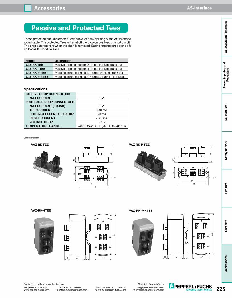
225Singapore: +65 6779 [email protected]
USA: +1 330 486 [email protected]
Germany: +49 621 [email protected]
Pepperl+Fuchs Groupwww.pepperl-fuchs.com
Subject to modifications without notice Copyright Pepperl+Fuchs
Accessories AS-Interface
Gat
eway
s an
d Sc
anne
rsPo
wer
Sup
plie
s an
d Re
peat
ers
I/O M
odul
esSa
fety
at W
ork
Sens
ors
Cord
sets
Acce
ssor
ies
Passive and Protected TeesThese protected and unprotected Tees allow for easy splitting of the AS-Interface round cable. The protected Tees will shut off the drop on overload or short circuit. The drop autorecovers when the short is removed. Each protected drop can be for up to one I/O module each.
Model DescriptionVAZ-RK-TEE Passive drop connector, 2 drops, trunk in, trunk outVAZ-RK-4TEE Passive drop connector, 4 drops, trunk in, trunk outVAZ-RK-P-TEE Protected drop connector, 1 drop, trunk in, trunk outVAZ-RK-P-4TEE Protected drop connector, 4 drops, trunk in, trunk out
Specifications PASSIVE DROP CONNECTORS
MAX CURRENT 8 APROTECTED DROP CONNECTORS
MAX CURRENT (TRUNK) 8 ATRIP CURRENT 240 mAHOLDING CURRENT AFTER TRIP 28 mARESET CURRENT < 28 mAVOLTAGE DROP < 1 V
TEMPERATURE RANGE -40 °F to +185 °F (-40 °C to +85 °C)
ø 3
7567
3613
40
VAZ-RK-TEE
VAZ-RK-4TEE
474512 11
113
VAZ-RK-P-TEE
ø 3
7567
2613
40VAZ-RK-P-4TEE
474512 11
113
Dimensions in mm
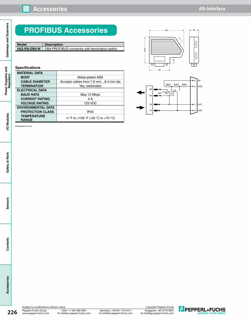
226 Singapore: +65 6779 [email protected]
USA: +1 330 486 [email protected]
Germany: +49 621 [email protected]
Pepperl+Fuchs Groupwww.pepperl-fuchs.com
Subject to modifications without notice Copyright Pepperl+Fuchs
Accessories AS-InterfaceG
atew
ays
and
Scan
ners
Pow
er S
uppl
ies
and
Repe
ater
sI/O
Mod
ules
Safe
ty a
t Wor
kSe
nsor
sCo
rdse
tsAc
cess
orie
s
1660
44.5
35
10
1A 8
OFF S1
D(N)
390Ω 220Ω 390Ω
1B
2A
2B
3
5
6
D(P)
GND
VP
ON
Specifications MATERIAL DATA
BODY Metal-plated ABSCABLE DIAMETER Accepts cables from 7.6 mm…8.4 mm diaTERMINATION Yes, switchable
ELECTRICAL DATABAUD RATE Max 12 MbpsCURRENT RATING 4 AVOLTAGE RATING 125 VDC
ENVIRONMENTAL DATAPROTECTION CLASS IP40TEMPERATURE RANGE -4 °F to +158 °F (-20 °C to +70 °C)
Model DescriptionVAZ-PB-DB9-W DB9 PROFIBUS connector with termination switch
PROFIBUS Accessories
Dimensions in mm
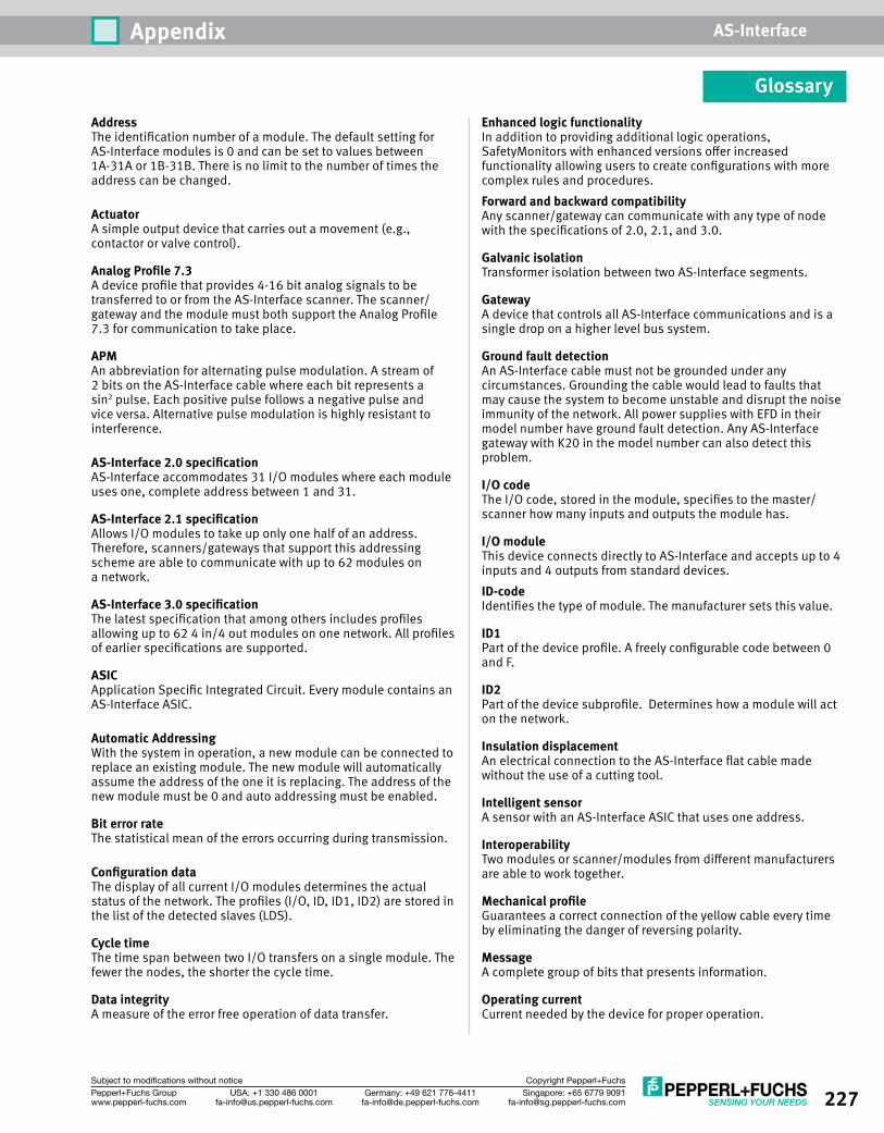
227Singapore: +65 6779 [email protected]
USA: +1 330 486 [email protected]
Germany: +49 621 [email protected]
Pepperl+Fuchs Groupwww.pepperl-fuchs.com
Subject to modifications without notice Copyright Pepperl+Fuchs
Appendix AS-Interface
GlossaryAddressThe identification number of a module. The default setting for AS-Interface modules is 0 and can be set to values between 1A-31A or 1B-31B. There is no limit to the number of times the address can be changed.
Actuator A simple output device that carries out a movement (e.g., contactor or valve control).
Analog Profile 7.3A device profile that provides 4-16 bit analog signals to be transferred to or from the AS-Interface scanner. The scanner/gateway and the module must both support the Analog Profile 7.3 for communication to take place.
APM An abbreviation for alternating pulse modulation. A stream of 2 bits on the AS-Interface cable where each bit represents a sin2 pulse. Each positive pulse follows a negative pulse and vice versa. Alternative pulse modulation is highly resistant to interference.
AS-Interface 2.0 specificationAS-Interface accommodates 31 I/O modules where each module uses one, complete address between 1 and 31.
AS-Interface 2.1 specificationAllows I/O modules to take up only one half of an address. Therefore, scanners/gateways that support this addressing scheme are able to communicate with up to 62 modules on a network.
AS-Interface 3.0 specificationThe latest specification that among others includes profiles allowing up to 62 4 in/4 out modules on one network. All profiles of earlier specifications are supported.
ASICApplication Specific Integrated Circuit. Every module contains an AS-Interface ASIC.
Automatic AddressingWith the system in operation, a new module can be connected to replace an existing module. The new module will automatically assume the address of the one it is replacing. The address of the new module must be 0 and auto addressing must be enabled.
Bit error rateThe statistical mean of the errors occurring during transmission.
Configuration dataThe display of all current I/O modules determines the actual status of the network. The profiles (I/O, ID, ID1, ID2) are stored in the list of the detected slaves (LDS).
Cycle timeThe time span between two I/O transfers on a single module. The fewer the nodes, the shorter the cycle time.
Data integrityA measure of the error free operation of data transfer.
Enhanced logic functionalityIn addition to providing additional logic operations, SafetyMonitors with enhanced versions offer increased functionality allowing users to create configurations with more complex rules and procedures.Forward and backward compatibilityAny scanner/gateway can communicate with any type of node with the specifications of 2.0, 2.1, and 3.0.
Galvanic isolationTransformer isolation between two AS-Interface segments.
Gateway A device that controls all AS-Interface communications and is a single drop on a higher level bus system.
Ground fault detectionAn AS-Interface cable must not be grounded under any circumstances. Grounding the cable would lead to faults that may cause the system to become unstable and disrupt the noise immunity of the network. All power supplies with EFD in their model number have ground fault detection. Any AS-Interface gateway with K20 in the model number can also detect this problem.
I/O codeThe I/O code, stored in the module, specifies to the master/scanner how many inputs and outputs the module has.
I/O moduleThis device connects directly to AS-Interface and accepts up to 4 inputs and 4 outputs from standard devices.ID-code Identifies the type of module. The manufacturer sets this value.
ID1Part of the device profile. A freely configurable code between 0 and F.
ID2Part of the device subprofile. Determines how a module will act on the network.
Insulation displacementAn electrical connection to the AS-Interface flat cable made without the use of a cutting tool.
Intelligent sensorA sensor with an AS-Interface ASIC that uses one address.
InteroperabilityTwo modules or scanner/modules from different manufacturers are able to work together.
Mechanical profileGuarantees a correct connection of the yellow cable every time by eliminating the danger of reversing polarity.
MessageA complete group of bits that presents information.
Operating currentCurrent needed by the device for proper operation.
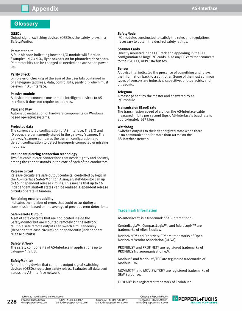
228 Singapore: +65 6779 [email protected]
USA: +1 330 486 [email protected]
Germany: +49 621 [email protected]
Pepperl+Fuchs Groupwww.pepperl-fuchs.com
Subject to modifications without notice Copyright Pepperl+Fuchs
Appendix AS-Interface
Glossary
OSSDsOutput signal switching devices (OSSDs), the safety relays in a SafetyMonitor.
Parameter bits A four-bit code indicating how the I/O module will function. Examples: N.C./N.O., light-on/dark-on for photoelectric sensors. Parameter bits can be changed as needed and are set on power up.
Parity checkSimple error checking of the sum of the user bits contained in one telegram (address, data, control bits, parity bit) which must be even in AS-Interface.
Passive moduleA device that connects one or more intelligent devices to AS-Interface. It does not require an address.
Plug and PlayAutomatic installation of hardware components on Windows based operating systems.
Projected dataThe current stored configuration of AS-Interface. The I/O and ID codes are permanently stored in the gateway/scanner. The gateway/scanner compares the current configuration and default configuration to detect improperly connected or missing modules.
Redundant piercing connection technologyTwo flat cable pierce connections that nestle tightly and securely among the copper strands in the core of each of the conductors.
Release circuitRelease circuits are safe output contacts, controlled by logic in the AS-Interface SafetyMonitor. A single SafetyMonitor can up to 16 independent release circuits. This means that up to 16 independent shut-off states can be realized. Dependent release circuits operate in tandem.
Remaining error probabilityIndicates the number of errors that could occur during a transmission based on the average of previous error detections.
Safe Remote OutputA set of safe contacts that are not located inside the SafetyMonitor but are mounted remotely on the network. Multiple safe remote outputs can switch simultaneously (dependent release circuits) or independently (independent release circuits)
Safety at WorkThe safety components of AS-Interface in applications up to category 4, SIL 3.
SafetyMonitorA monitoring device that contains output signal switching devices (OSSDs) replacing safety relays. Evaluates all data sent across the AS-Interface network.
Trademark Information
AS-Interface™ is a trademark of AS-International.
ControlLogix™, CompactLogix™, and MicroLogix™ are trademarks of Allen Bradley.
DeviceNet™ and EtherNet/IP™ are trademarks of Open DeviceNet Vendor Association (ODVA).
PROFIBUS® and PROFINET® are registered trademarks of PROFIBUS Nutzerorganisation e.V.
Modbus® and Modbus®/TCP are registered trademarks of Modbus-IDA.
MOVIMOT® and MOVISWITCH® are registered trademarks of SEW Eurodrive.
ECOLAB® is a registered trademark of Ecolab Inc.
SafetyNodeI/O modules constructed to satisfy the rules and regulations necessary to obtain the desired safety ratings.
Scanner CardsDirectly mounted in the PLC rack and appearing in the PLC configuration as large I/O cards. Also any PC card that connects to the ISA, PCI, or PC104 busses.
Sensor A device that indicates the presence of something and relays the information back to a controller. Some of the most common types of sensors are inductive, capacitive, photoelectric, and ultrasonic.
TelegramA message sent by the master and answered by an I/O module.
Transmission (Baud) rate The transmission speed of a bit on the AS-Interface cable measured in bits per second (bps). AS-Interface’s baud rate is approximately 167 kbps.
WatchdogSwitches outputs to their deenergized state when there is no communication for more than 40 ms on the AS-Interface network.
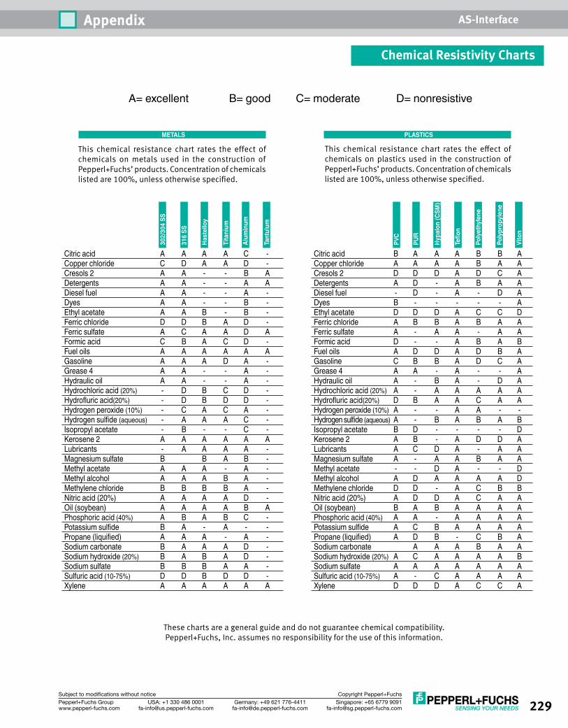
229Singapore: +65 6779 [email protected]
USA: +1 330 486 [email protected]
Germany: +49 621 [email protected]
Pepperl+Fuchs Groupwww.pepperl-fuchs.com
Subject to modifications without notice Copyright Pepperl+Fuchs
Appendix AS-Interface
This chemical resistance chart rates the effect of chemicals on metals used in the construction of Pepperl+Fuchs’ products. Concentration of chemicals listed are 100%, unless otherwise specified.
These charts are a general guide and do not guarantee chemical compatibility. Pepperl+Fuchs, Inc. assumes no responsibility for the use of this information.
Citric acid A A A A C - Copper chloride C D A A D - Cresols 2 A A - - B A Detergents A A - - A A Diesel fuel A A - - A - Dyes A A - - B - Ethyl acetate A A B - B - Ferric chloride D D B A D - Ferric sulfate A C A A D A Formic acid C B A C D - Fuel oils A A A A A A Gasoline A A A D A - Grease 4 A A - - A - Hydraulic oil A A - - A - Hydrochloric acid (20%) - D B C D -Hydrofluricacid(20%) - D B D D - Hydrogen peroxide (10%) - C A C A -Hydrogensulfide(aqueous) - A A A C - Isopropyl acetate - B - - C - Kerosene 2 A A A A A A Lubricants - A A A A - Magnesium sulfate B B A B - Methyl acetate A A A - A - Methyl alcohol A A A B A - Methylene chloride B B B B A - Nitric acid (20%) A A A A D - Oil (soybean) A A A A B A Phosphoric acid (40%) A B A B C -Potassiumsulfide B A - A - -Propane(liquified) A A A - A - Sodium carbonate B A A A D - Sodium hydroxide (20%) B A B A D - Sodium sulfate B B B A A - Sulfuric acid (10-75%) D D B D D - Xylene A A A A A A
This chemical resistance chart rates the effect of chemicals on plastics used in the construction of Pepperl+Fuchs’ products. Concentration of chemicals listed are 100%, unless otherwise specified.
Citric acid B A A A B B A Copper chloride A A A A B A A Cresols 2 D D D A D C A Detergents A D - A B A A Diesel fuel - D - A - D A Dyes B - - - - - A Ethyl acetate D D D A C C D Ferric chloride A B B A B A A Ferric sulfate A - A A - A A Formic acid D - - A B A B Fuel oils A D D A D B A Gasoline C B B A D C A Grease 4 A A - A - - A Hydraulic oil A - B A - D A Hydrochloric acid (20%) A - A A A A AHydrofluricacid(20%) D B A A C A A Hydrogen peroxide (10%) A - - A A - -Hydrogensulfide(aqueous) A - B A B A B Isopropyl acetate B D - - - - D Kerosene 2 A B - A D D A Lubricants A C D A - A A Magnesium sulfate A - A A B A A Methyl acetate - - D A - - D Methyl alcohol A D A A A A D Methylene chloride D D - A C B B Nitric acid (20%) A D D A C A A Oil (soybean) B A B A A A A Phosphoric acid (40%) A A - A A A APotassiumsulfide A C B A A A APropane(liquified) A D B - C B A Sodium carbonate A A A B A A Sodium hydroxide (20%) A C A A A A B Sodium sulfate A A A A A A A Sulfuric acid (10-75%) A - C A A A A Xylene D D D A C C A
Alum
inum
Tant
ulum
Tita
nium
316
SS
Hast
ello
y
302/
304
SS
A= excellent B= good C= moderate D= nonresistive
Poly
ethy
lene
Poly
prop
ylen
e
Teflon
PUR
Hypa
lon
(CSM
)
PVC
Vito
n
METALS PLASTICS
Chemical Resistivity Charts
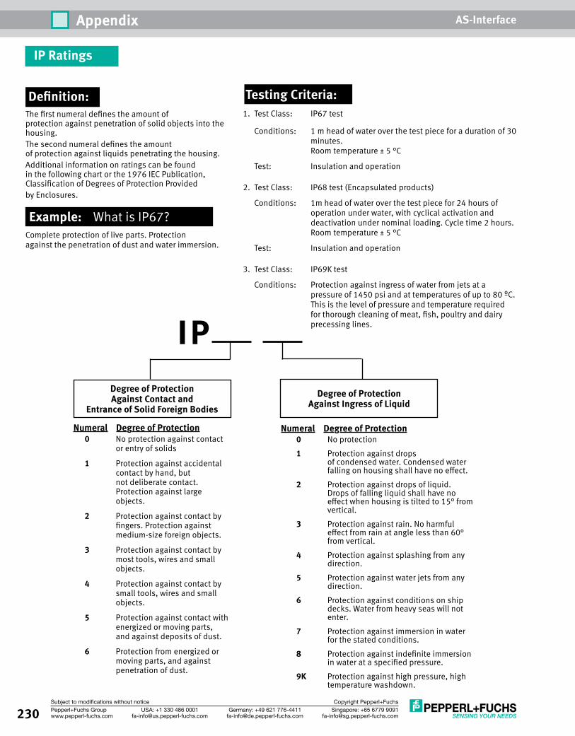
230 Singapore: +65 6779 [email protected]
USA: +1 330 486 [email protected]
Germany: +49 621 [email protected]
Pepperl+Fuchs Groupwww.pepperl-fuchs.com
Subject to modifications without notice Copyright Pepperl+Fuchs
Appendix AS-Interface
Definition:The first numeral defines the amount of protection against penetration of solid objects into the housing. The second numeral defines the amount of protection against liquids penetrating the housing. Additional information on ratings can be found in the following chart or the 1976 IEC Publication, Classification of Degrees of Protection Provided by Enclosures.
Example: What is IP67?Complete protection of live parts. Protection against the penetration of dust and water immersion.
Testing Criteria:1. Test Class: IP67 test
Conditions: 1 m head of water over the test piece for a duration of 30 minutes. Room temperature ± 5 °C
Test: Insulation and operation
2. Test Class: IP68 test (Encapsulated products)
Conditions: 1m head of water over the test piece for 24 hours of operation under water, with cyclical activation and deactivation under nominal loading. Cycle time 2 hours. Room temperature ± 5 °C
Test: Insulation and operation
3. Test Class: IP69K test
Conditions: Protection against ingress of water from jets at a pressure of 1450 psi and at temperatures of up to 80 ºC. This is the level of pressure and temperature required for thorough cleaning of meat, fish, poultry and dairy precessing lines. IP
Degree of Protection Against Contact and
Entrance of Solid Foreign BodiesDegree of Protection
Against Ingress of Liquid
Numeral Degree of Protection 0 No protection 1 Protection against drops
of condensed water. Condensed water falling on housing shall have no effect.
2 Protection against drops of liquid. Drops of falling liquid shall have no effect when housing is tilted to 15° from vertical.
3 Protection against rain. No harmful effect from rain at angle less than 60° from vertical.
4 Protection against splashing from any direction.
5 Protection against water jets from any direction.
6 Protection against conditions on ship decks. Water from heavy seas will not enter.
7 Protection against immersion in water for the stated conditions.
8 Protection against indefinite immersion in water at a specified pressure.
9K Protection against high pressure, high temperature washdown.
Numeral Degree of Protection 0 No protection against contact
or entry of solids
1 Protection against accidental contact by hand, but not deliberate contact. Protection against large objects.
2 Protection against contact by fingers. Protection against medium-size foreign objects.
3 Protection against contact by most tools, wires and small objects.
4 Protection against contact by small tools, wires and small objects.
5 Protection against contact with energized or moving parts, and against deposits of dust.
6 Protection from energized or moving parts, and against penetration of dust.
IP Ratings
AAB12 .............................................................. 168AB18 .............................................................. 168AB30 .............................................................. 168
BBF5-30 ............................................................ 168BF12 ............................................................... 168BF18 ............................................................... 168BF30 ............................................................... 168BSM58............................................................ 192BSS58 ............................................................ 192BT 65 .............................................................. 178BT 115A .......................................................... 178BVM58 ............................................................ 188BVS58 ............................................................ 188
FFE-RR1 ............................................................ 186
KK17-STR-24..30VDC-5A ...................................... 68K24-STR-24..30VDC-10A .................................... 68K34-STR-24..30V-3X500VAC-10A ....................... 68K-ADP2 RPI ................................................ 34, 213
LLD28-LAS-F1-B3B/73c ..................................... 183LV28-LAS-F1-B3B/73c ..................................... 183
MMH4-2057 ...................................................... 171MH4-2681 UNI ................................................ 171MH V1-BIT-M12 ............................................... 223MH V1-SCREWDRIVER ...................................... 223MH V3-BIT-M8 ................................................. 223
NNBB6-F-B3B .................................................... 175NBB15-30GM60-B3B-V1 ................................. 167NBB20-L2-B3B-V1 ........................................... 173NBB20-U1-B3B ............................................... 170NBN30-L2-B3B-V1 ........................................... 173NBN40-L2-B3B-V1 ........................................... 173NBN40-U1-B3B ............................................... 170NCB4-12GM60-B3B-V1 .................................... 166NCB5-18GM60-B3B-V1 .................................... 166NCN3-F31-B3B-V1-K ........................................ 177NCN3-F31-B3B-V1-V1 ...................................... 177NCN4-12GM60-B3B-C2-V1 .............................. 166NCN8-18GM60-B3B-V1 ................................... 167
OOMH-21 .......................................................... 185OMH-21-T ....................................................... 185OMH-MLV11-K ................................................. 185OMH-RL2-H ..................................................... 185OMH-RL2-S...................................................... 186OMH-RL25 ...................................................... 185
PPG11-1/2NPT .................63, 66, 94, 118, 122, 222PG11 CORD GRIP ....................... 94, 118, 122, 222
RREF-A25 .......................................................... 187REF-A35 .......................................................... 187REF-H32 .......................................................... 186REF-H51x72 .................................................... 186REF-H100 ........................................................ 186REF-MA21 ....................................................... 187REF-MH20 ....................................................... 187REF-MH23 ....................................................... 187REF-MH50 ....................................................... 187REF-MH78 ....................................................... 187RL28-8-H-700-RT-B3B/73c .............................. 180RL28-55-B3B/73c ........................................... 181RL28-55-LAS-B3B/73c..................................... 181RL28-55-V-B3B/73c ........................................ 182RT1 X 2............................................................ 187RT1 X 100........................................................ 187RT2 X 100........................................................ 187RT3 X 100........................................................ 187
SSST-ASI-SLC ....................................................... 30
UU-G1F ............................................................. 217U-G1FA ........................................................... 217U-G1FF ...................................................... 63, 217U-G1FFA .............................94, 118, 122, 142, 217U-G1PP ..................63, 66, 94, 118, 122, 142, 217U-G2FF ...................................................... 77, 217U-G2FF-DIN ..................................................... 217U-G3FF ...................................................... 77, 217U-G3FF-DIN ..................................................... 217
VV1-CLIP ................................................... 142, 223V1-G-0,3M-PUR-ABG-V1-W-Y ............................ 203V1-G-0.5/2.5M-PUR-V1-G ................................ 199V1-G-2M-PUR-V1-G .......................................... 199V1-G-2M-PUR-V1-W ......................................... 199V1-G-2M-PVC .................................................. 198V1-G-2M-PVC-V1-G .................................. 199, 212V1-G-2M-PVC-V1-W .......................................... 199V1-G-.3M-T-0M-V1-G ........................................ 206V1-G-5M-PUR-V1-G .......................................... 199V1-G-5M-PUR-V1-W ......................................... 199V1-G-5M-PVC .................................................. 198V1-G-5M-PVC-V1-G .......................................... 199V1-G-5M-PVC-V1-W .......................................... 199V1-G-10M-PUR-V1-G ........................................ 199V1-G-10M-PUR-V1-W ....................................... 199V1-G-10M-PVC ................................................ 198V1-G-10M-PVC-V1-G ........................................ 199V1-G-10M-PVC-V1-W ........................................ 199V1-G-15M-PVC ................................................ 198V1-G-20M-PVC ................................................ 198V1-G-42-0,3M-PUR-ABG-V1-W-Y ....................... 203V1-G-V1-Y904948 ........................................... 202V1S-G-2M-PVC ........................................ 198, 212V1S-G-5M-PVC ................................................ 198V1S-G-10M-PVC .............................................. 198V1S-W-2M-PVC ................................................ 198
231Singapore: +65 6779 [email protected]
USA: +1 330 486 [email protected]
Germany: +49 621 [email protected]
Pepperl+Fuchs Groupwww.pepperl-fuchs.com
Subject to modifications without notice Copyright Pepperl+Fuchs
Model Number Index AS-Interface
V1S-W-5M-PVC ................................................ 198V1S-W-10M-PVC .............................................. 198V1-W-0.5/2.5M-PUR-V1-G ................................ 199V1-W-2M-PUR-V1-G ......................................... 199V1-W-2M-PVC .................................................. 198V1-W-2M-PVC-V1-G .......................................... 199V1-W-5M-PUR-V1-G ......................................... 199V1-W-5M-PVC .................................................. 198V1-W-5M-PVC-V1-G .......................................... 199V1-W-10M-PUR-V1-G ....................................... 199V1-W-10M-PVC ................................................ 198V1-W-10M-PVC-V1-G ........................................ 199V1-W-15M-PVC ................................................ 198V1-W-20M-PVC ................................................ 198V1-W-42-2M-PVC-V11-W .................................. 201V1-W-42-5M-PVC-V11-W .................................. 201V3-GM-1M-PUR-V3-GM .................................... 205V3-GM-2M-PUR-ABG43-V1-G ........................... 158V3-GM-2M-PUR-V3-GM .................................... 205V3-GM-5M-PUR-ABG43-V1-G ........................... 158V3-GM-5M-PUR-V3-GM .................................... 205V3-GM-10M-PUR-V3-GM .................................. 205V11-G-1M-PVC-V11-G ...................................... 200V11-G-2M-PVC-V11-G ...................................... 200V11-G-3M-PVC-V11-G ...................................... 200V11-G-4M-PVC-V11-G ...................................... 200V11-G-5M-PVC-V11-G ...................................... 200V11-G-6M-PVC-V11-G ...................................... 200V11-G-7M-PVC-V11-G ...................................... 200V11-G-8M-PVC-V11-G ...................................... 200V11-G-10M-PVC-V11-G .................................... 200V11S-T-V11 ..................................................... 208V15-G-2M-PVC ................................................ 198V15-G-5M-PVC ................................................ 198V15-G-10M-PVC .............................................. 198V15S-G-2M-PVC .............................................. 198V15S-G-5M-PVC .............................................. 198V15S-G-10M-PVC ............................................ 198V15S-TEE-V15 ................................................. 209V15S-T-V15 ..................................................... 207V15S-YEE-V15 ................................................. 209V15-W-2M-PVC ................................................ 198V15-W-5M-PVC ................................................ 198V15-W-10M-PVC .............................................. 198V31-GM-0.1M-PUR-V1-G .................................. 204V31-GM-42-2M-PVC-V11-W .............................. 204VAA-2E1A-F85A-S-V1 ....................................... 144VAA-2E1A-G10-SAJ/EA2L-1M ............................ 136VAA-2E1A-G10-SAJ/EA2L-2X1M ........................ 136VAA-2E1A-IER1-S-1M-V1 .................................. 153VAA-2E-IER2-S-1M-V1 ...................................... 153VAA-2E1A-PM-S ............................................... 144VAA-2E2A-G12-SAJ/EA2L ................................. 136VAA-2E2A-IM1-J-S-V1 ....................................... 147VAA-2E2A-KE1-S/E2 ........................................ 135VAA-2E3A-LIM1-PL-J-S-V1 ................................. 148VAA-2E3A-LIM1-PL-L-S-V1 ................................ 148VAA-2E3A-LIM1-PU-J-S-V1 ................................ 148VAA-2E3A-LIM1-PU-L-S-V1 ............................... 148VAA-2EA-G1-ZE/P-S ......................................... 120VAA-2EA-G1-ZE/P-V2A ..................................... 120VAA-2EA-G2-ZA/EA2 .......................................... 74VAA-2E-F85A-S-V1 ........................................... 144VAA-2E-G4-SE .................................................. 137VAA-2E-IER2-S-0,15M-V1 ................................. 153VAA-2E-IM1-J-S-V1 ........................................... 147VAA-2E-KE1-S .................................................. 135VAA-2E-PM-S ................................................... 144VAA-3E-HH30-J-S-V1 ........................................ 160VAA-4A-70MM ................................................. 115VAA-4A-G12-EA2L .............................................. 79VAA-4E2A-G1-ZE/PEXT-S .................................. 120VAA-4E2A-G1-ZE/P-S ....................................... 120VAA-4E4A-CB1-Z/E2 ........................................ 103VAA-4E4A-CB2-Z/E2 ........................................ 103VAA-4E4A-G2-ZA/EA2 ........................................ 74
232 Singapore: +65 6779 [email protected]
USA: +1 330 486 [email protected]
Germany: +49 621 [email protected]
Pepperl+Fuchs Groupwww.pepperl-fuchs.com
Subject to modifications without notice Copyright Pepperl+Fuchs
Model Number Index AS-Interface
VAA-4E4A-G4-ZE/E2 .......................................... 92VAA-4E4A-G11-ZAJ/EA2L-F ................................. 83VAA-4E4A-G11-ZAJ/EA2L-V1............................... 83VAA-4E4A-G12-ZAJ/EA2L ................................... 79VAA-4E4A-G12-ZAL/EA2L ................................... 79VAA-4E4A-G16-ZEJ/E2L ...................................... 96VAA-4E4A-KE1-Z/E2......................................... 103VAA-4E4A-KE-ZEJQ/E2L ...................................... 99VAA-4E4A-KE-ZE/R ............................................. 99VAA-4E-G4-ZE .................................................... 92VAA-4E-IEI1-CONTROL-J-S ................................. 156VAA-LT3-F86-V1 ............................................... 114VAN-24DC-K28 .................................................. 62VAN-115/230AC-K16 ......................................... 59VAN-115/230AC-K19 ......................................... 59VAN-115/230AC-K27 ......................................... 59VAN-G4-PE-4A ................................................... 62VAN-KE2-2PE ..................................................... 62VAR-G4F ............................................................ 65VAR-KE3-TERM ................................................... 65VAS-1A1L-K12 ................................................. 130VAS-1A-K12 .................................................... 130VAS-2A1L-K12 ................................................. 130VAS-2A1L-K31 ................................................. 130VAS-2A8L-KE4-8SE .......................................... 130VAS-2A-K12 .................................................... 130VAS-4A16L-K31 ............................................... 130VAZ-2FK-CL2 .................................................... 223VAZ-2FK-G10-BRIDGE ....................................... 221VAZ-2FK-GLAND-12NPT .................................... 222VAZ-2FK-GLAND-M2- ........................................ 222VAZ-2T1-FK-G10-1M-PUR-V1-G ......................... 220VAZ-2T1-FK-G10-1M-PUR-V1-W ......................... 220VAZ-2T1-FK-G10-2M-PUR-V1-G ......................... 220VAZ-2T1-FK-G10-2M-PUR-V1-W ......................... 220VAZ-2T1-FK-G10-5M-PUR-V1-G ......................... 220VAZ-2T1-FK-G10-5M-PUR-V1-W ......................... 220VAZ-2T1-FK-G10-CLAMP1 ................................. 221VAZ-2T1-FK-G10-V1 ......................................... 219VAZ-2T2-FK-G10-V1 ......................................... 219VAZ-2T8-G11-F ................................................ 219VAZ-2T8-G11-V1 .............................................. 219VAZ-9VDC-CHRG-115V ..................................... 212VAZ-ANALYZER ................................................. 214VAZ-CLAMP-70MM ........................................... 115VAZ-CLAMP-70MM-90° .................................... 115VAZ-CLIP-G12 .................................................... 81VAZ-CTR ................................................ 38, 45, 53VAZ-DK-G1....................................................... 217VAZ-DN-SIM-USB ....................................... 38, 215VAZ-FBST 500-PLC GY ...................................... 224VAZ-FK-CL1 ...................................................... 223VAZ-FK-ED2 ..................................................... 223VAZ-FK-GLAND-12NPT ...................................... 222VAZ-FK-GLAND-M20 ......................................... 222VAZ-FK-R-BK .................................................... 218VAZ-FK-R-BK-1000M ......................................... 218VAZ-FK-R-STRIPPER .......................................... 218VAZ-FK-R-STRIPPER-BLADES .............................. 218VAZ-FK-R-YE ..................................................... 218VAZ-FK-R-YE-1000M ......................................... 218VAZ-FK-S-BK..................................................... 218VAZ-FK-S-BK-2,5MM ......................................... 218VAZ-FK-S-BK-1000M ......................................... 218VAZ-FK-S-BK-SEAL ............................................ 114VAZ-FK-S-YE ..................................................... 218VAZ-FK-S-YE-1000M ......................................... 218VAZ-FK-S-YE-SAFETY ......................................... 218VAZ-FLASH-70MM-RD ...................................... 115VAZ-FLASH-70MM-YE ....................................... 115VAZ-G4-B1 ...................................................... 223VAZ-G10-TERM ................................................ 216VAZ-HH30-BRACKET ......................................... 159VAZ-HORN-70MM-0..100DBA-8TONE ................ 115VAZ-HORN-70MM-85DBA ................................. 115VAZ-HORN-70MM-105DBA ............................... 115
VAZ-IEI1-READER1-S-V3 ................................... 156VAZ-IEI1-TAG1-S ............................................... 156VAZ-IER1-ACTUATOR1-S.................................... 153VAZ-IER2-ACTUATOR2-S.................................... 153VAZ-IM1-90°-BOLT-S ........................................ 151VAZ-IM1-BASE-BOLT-S ...................................... 151VAZ-IM1-BASE-S .............................................. 151VAZ-IM1-BOLT-S ............................................... 151VAZ-IM1-LR-RADIUS-BOLT-S .............................. 151VAZ-IM1-TD-RADIUS-BOLT-S ............................. 151VAZ-LAMP-70MM-BU ....................................... 115VAZ-LAMP-70MM-BULB-5W/24V .............. 115, 118VAZ-LAMP-70MM-CL ........................................ 115VAZ-LAMP-70MM-GN ....................................... 115VAZ-LAMP-70MM-RD ....................................... 115VAZ-LAMP-70MM-YE ........................................ 115VAZ-LED-70MM-BU .......................................... 115VAZ-LED-70MM-CL ........................................... 115VAZ-LED-70MM-GN .......................................... 115VAZ-LED-70MM-RD .......................................... 115VAZ-LED-70MM-YE ........................................... 115VAZ-MH-1/2”Conduit-70MM ............................ 118VAZ-MH 90°-70MM .......................................... 115VAZ-MH 100-70MM ......................................... 115VAZ-PB-DB9-W .......................................... 45, 226VAZ-PB-SIM ............................................... 45, 215VAZ-PG11-FKD ................................................. 222VAZ-PK-1,5M-V1-G ........................................... 212VAZ-PK-FK-0,2M-V1-W ........................ 90, 142, 212VAZ-PLC-OSC-120UC/48DC/100/SEN ............... 224VAZ-R4-R2 ................................................. 53, 215VAZ-RK-4TEE .................................................... 225VAZ-RK-P-4TEE ................................................. 225VAZ-RK-P-TEE ................................................... 225VAZ-RK-PVC-ABG 2X1,3-GY 100M ..................... 218VAZ-RK-TEE ...................................................... 225VAZ-SIMON-R2......................................... 133, 213VAZ-SIMON+-R2-1,8M-PS/2 ............... 45, 133, 213VAZ-SIMON-RJ45 ...................................... 133, 213VAZ-SIMON-USB ...................................... 133, 213VAZ-SW-ACT32 ...................34, 38, 45, 50, 53, 213VAZ-SW-SIMON+ .......................... 45, 50, 133, 213VAZ-T1-FK-G10-0,3M-PUR-V1-G ........................ 220VAZ-T1-FK-G10-1M-PUR-V1-G ........................... 220VAZ-T1-FK-G10-1M-PUR-V1-W ........................... 220VAZ-T1-FK-G10-2M-PUR-V1-G ........................... 220VAZ-T1-FK-G10-2M-PUR-V1-W ........................... 220VAZ-T1-FK-G10-5M-PUR-V1-G ........................... 220VAZ-T1-FK-G10-5M-PUR-V1-W ........................... 220VAZ-T1-FK-G10-CLAMP1 ................................... 221VAZ-T1-FK-G10-V1 ............................................ 219VAZ-T1-FK-M20 ........................................ 169, 222VAZ-T1-FK-PG9 ................................................. 222VAZ-T1-FK-PG11 ............................................... 222VAZ-TUBE400-70MM ....................................... 118VAZ-TUBE-BASE-70MM .................................... 118VAZ-TUNER ...................................................... 216VAZ-V1-B3 ..................................... 77, 81, 86, 223VAZ-V3-B ................................................... 97, 223VBA-1E3A-M18-ZE/E2-V1 ................................ 124VBA-2A-G4-I .................................................... 107VBA-2A-G4-U ................................................... 107VBA-2A-G11-I-F ............................................... 107VBA-2A-G11-I-V1 ............................................. 107VBA-2A-KE2-I/U............................................... 108VBA-2E1A-G10-ZAL/E2L-1M-2V1-W .................... 88VBA-2E2A-G2-ZA/EA2 ........................................ 74VBA-2E2A-G2-ZEJ/XE2J ...................................... 74VBA-2E2A-G4-ZE/E2 .......................................... 92VBA-2E2A-G12-ZAJ/EA2L ................................... 79VBA-2E-G4-I .................................................... 107VBA-2E-G4-U ................................................... 107VBA-2E-G10-ZAJ-1M-V1-W.................................. 88VBA-2E-G10-ZEJ-1M-2V1-W ................................ 88VBA-2E-G11-I/U/PT100-F ................................. 107VBA-2E-G11-I/U/PT100-V1 .............................. 107
VBA-2E-KE2-I/U ............................................... 108VBA-2E-KE2-I/U-V3.0 ....................................... 108VBA-4A-G11-I/U-F ........................................... 107VBA-4E1A-KE3-ZEJ/SR ..................................... 138VBA-4E2A-G1-ZE/PEXT-S .................................. 120VBA-4E2A-G1-ZE/P-S ....................................... 120VBA-4E2A-G2-XE/E2 .......................................... 74VBA-4E2A-KE1-Z/E2 ........................................ 103VBA-4E3A-G2-ZA/EA2 ........................................ 74VBA-4E3A-G4-ZE/E2 .......................................... 92VBA-4E3A-G12-ZAJ/EA2L ................................... 79VBA-4E3A-KE-ZEJQ/E2L...................................... 99VBA-4E3A-KE-ZE/R ............................................ 99VBA-4E4A-CB1-ZEJ/E2J .................................... 103VBA-4E4A-CB1-ZEJ/E2J-FL ................................ 103VBA-4E4A-G2-ZA/EA2 ........................................ 74VBA-4E4A-G4-ZE/E2 .......................................... 92VBA-4E4A-G11-ZAJ/EA2L-F ................................. 83VBA-4E4A-G11-ZAJ/EA2L-V1 .............................. 83VBA-4E4A-G12-XEL ............................................ 79VBA-4E4A-G12-ZAJ/EA2L ................................... 79VBA-4E4A-G12-ZAL/EA2L................................... 79VBA-4E4A-G16-ZEJ/E2L ..................................... 96VBA-4E4A-KE-ZEJQ/E2L...................................... 99VBA-4E4A-KE-ZE/R ............................................ 99VBA-4E4E-G12-ZAJ ............................................ 79VBA-4E-G2-ZA ................................................... 74VBA-4E-G4-PT100 ............................................ 107VBA-4E-G4-ZE.................................................... 92VBA-4E-G11-ZAJ-F .............................................. 83VBA-4E-G11-ZAJ-V1 ........................................... 83VBA-4E-G12-ZAJ ................................................ 79VBA-4E-G12-ZAL ................................................ 79VBA-4E-G16-ZEJ................................................. 96VBA-4E-KE1-Z .................................................. 103VBA-4E-KE-ZEJQ ................................................. 99VBA-8E-G2-ZA ................................................... 74VBA-LT2-G1 ..................................................... 114VBG-DN-K20-D .................................................. 36VBG-DN-K20-DMD ............................................. 36VBG-DN-K20-DMD-BV ........................................ 36VBG-ENX-K20-D ................................................. 47VBG-ENX-K20-DMD ............................................ 47VBG-ENX-K30-DMD-S16 ..................................... 48VBG-MOD-K20-D ............................................... 52VBG-PB-K20-D ................................................... 40VBG-PB-K20-DMD .............................................. 40VBG-PB-K20-DMD-BV......................................... 40VBG-PB-K25 ...................................................... 40VBG-PB-K30-DMD-S16 ....................................... 41VBG-PB-K30-D-S16 ............................................ 41VBG-PN-K20-D................................................... 47VBG-PN-K20-DMD ............................................. 47VBG-PNS-K30-DMD ........................................... 48VBM-CLX-DM ..................................................... 30VBM-CTR-K20-R2 ............................................... 52VBM-MLX/CPLX ................................................. 30VBP-HH1-V3.0-110V ........................................ 212VBP-HH1-V3.0-KIT-110V .................................. 212

SPOTLIGHT on AS-Interface
Visit us at www.pepperl-fuchs.us or call us at 330-486-0001
SPOTLIGHT on Identification Products
Visit us at www.pepperl-fuchs.us or call us at 330-486-0001
Safety ProductsFully approved low-cost networkable safety system • Panel and enclosure mount e-stops • Safety modules for gates, light
curtains, and perimeter guarding • Approved by NFPA, UL, and OSHA • Safe to Cat 4/ SIL 3
See pages 125-162
Advanced Gateways/Safety ControllerGateways with advanced diagnostics for quick troubleshooting • Duplicate address, noise, and
ground fault detection built in • RS232 port for diagnostic
monitoring of network • Advanced graphical display • Ethernet/IP support allows direct
integration with modern Allen-Bradley PLCs
• Removable memory card
See pages 27-54
Tool-Free I/O Modules No tools are required to install or remove this module from the network. The module snaps in and a makes secure connection every time.• Stainless steel installation bar clicks in for secure
worry free connection • 1/2-turn SPEEDCON I/O connection for
fast installation • Gold plated machined pins for
superior performance • Quick change top for easy
module swapping • Outputs with RED
overload indication right at each connector
See pages 78-81
New Safety Interlock SwitchesAS-Interface mechanical safety interlock switches are used on doors and gates to restrict access.• Direct connection to AS-Interface • Power to lock/unlock options • AS-Interface or auxiliary
power options • Manual override
integrated • Large selection of
unique keys• Rugged IP67 water-
tight housing
See pages 146-151
Enclosure Style ModulesStandard and low profile housings for J-boxes and enclosures • Class I, Div. 2 approved for
hazardous locations • Color-coded, keyed, removable
terminals included with modules • Accessories to connect to any
120 VAC input • Input power selectable,
AS-Interface or auxiliary power
See pages 98-106
Applications In:• Material handling, warehousing, and inventory control• Printing, labeling, sorting, bulk mailing, and inserting• Automotive and allied industries• Pharmaceutical & medical instrumentation• Factory automation & electronics
Handheld SolutionsPepperl+Fuchs handheld solutions are rugged, light weight, and feature full graphical displays. They are often used for inventory management, offline write stations and cordless tracking systems.• Read/write data to any P+F
or ISO standard RFID tag• Wireless• Full graphical display with
keyboard• Will read 1-D or 2-D bar codes• Includes RS-232 / PS2 / USB support
IDENTControl SolutionsPepperl+Fuchs offers a wide selection of RFID readers for factory automation. IDENTControl is unique because of it's metal housing, graphical display, and universal connectivity to low frequency, high frequency and microwave type read heads.• Metal housing IP67• Over 50 different tags available• 14 different read head styles• EtherNet/IP and DeviceNet connectivity • Modbus/TCP, TCP/IP, PROFINET,
PROFIBUS, RS-232 supported• Email notification / web page configuration• IDENTControl compact 1- and 2-channel
versions available
Need Help Solving a Tough Application?Pepperl+Fuchs wants to ensure that you receive the service and support you need when you need it, 24 hours every day. You can find CAD drawings, download product data sheets, or request free literature. Get it all on the web at www.pepperl-fuchs.us.
Need More? Ask an Expert.With a click of the mouse, you can get advice from engineers who are experts in AS-Interface technology, who are familiar with a wide range of applications, and who can help you solve your most challenging production requirements. For reliable advice, visit www.pepperl-fuchs.us/askfa and ask an expert.
Magnetic and RFID Safety Interlock SwitchesNoncontact safety devices are designed to be a low cost safety option for use in wet and dirty environments.• IP69K watertight housing • All AS-Interface powered • Tamper-resistant coded magnet
actuator• RFID heads have no mechanical
components for long lasting reliability
• Guard up to four doors on one controller
See pages 152-158

FACTORY AUTOMATION
REFERENCE & BUYER'S GUIDEAS-INTERFACE PRODUCTS
Subject to modifications • © 2012 PEPPERL+FUCHS, INC. • Printed in USA • Part No. 910247 01/12
www.pepperl-fuchs.us
Reference & Buyer's Guide
Pepperl+Fuchs sets the standard in quality and innovative technology for the world of automation. Our expertise, dedication, and heritage of innovation have driven us to develop the largest and most versatile line of industrial sensor technologies and interface components in the world. With our global presence, reliable service, and flexible production facilities, Pepperl+Fuchs delivers complete solutions for your automation requirements—wherever you need us.
FACTORY AUTOMATION – SENSING YOUR NEEDS
AS-Interface Products
Worldwide HeadquartersPepperl+Fuchs GmbH · Mannheim · GermanyE-mail: [email protected]
USA HeadquartersPepperl+Fuchs Inc. · Twinsburg · USAE-mail: [email protected]
Asia Pacific HeadquartersPepperl+Fuchs Pte Ltd · SingaporeCompany Registration no. 199003130EE-mail: [email protected]
ContactPepperl+Fuchs Inc.1600 Enterprise ParkwayTwinsburg, Ohio 44087 · USATel. +1 330 486-0001 · Fax +1 330 405-4710E-mail: [email protected]
Edition 6.0
Edition 6.0
Related Documents