AIRCRAFT ENGINES ref. no.: OM-912 i | part no.: 898740

Welcome message from author
This document is posted to help you gain knowledge. Please leave a comment to let me know what you think about it! Share it to your friends and learn new things together.
Transcript
AIRCRAFT ENGINES
ref. no.: OM-912 i | part no.: 898740
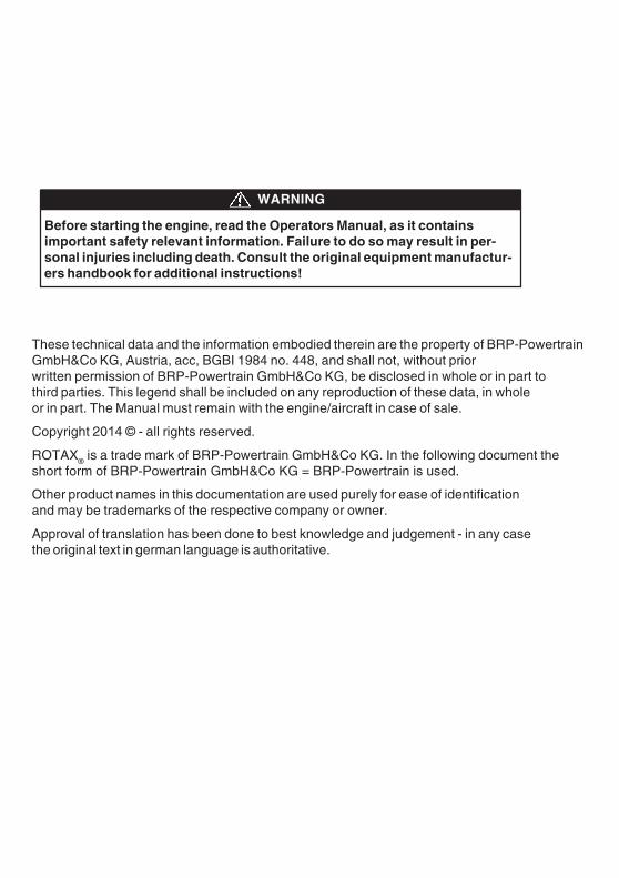
Before starting the engine, read the Operators Manual, as it containsimportant safety relevant information. Failure to do so may result in per-sonal injuries including death. Consult the original equipment manufactur-ers handbook for additional instructions!
WARNING
These technical data and the information embodied therein are the property of BRP-PowertrainGmbH&Co KG, Austria, acc, BGBI 1984 no. 448, and shall not, without priorwritten permission of BRP-Powertrain GmbH&Co KG, be disclosed in whole or in part tothird parties. This legend shall be included on any reproduction of these data, in wholeor in part. The Manual must remain with the engine/aircraft in case of sale.
Copyright 2014 © - all rights reserved.
ROTAX® is a trade mark of BRP-Powertrain GmbH&Co KG. In the following document theshort form of BRP-Powertrain GmbH&Co KG = BRP-Powertrain is used.
Other product names in this documentation are used purely for ease of identificationand may be trademarks of the respective company or owner.
Approval of translation has been done to best knowledge and judgement - in any casethe original text in german language is authoritative.
d052
70.fm
Introduction
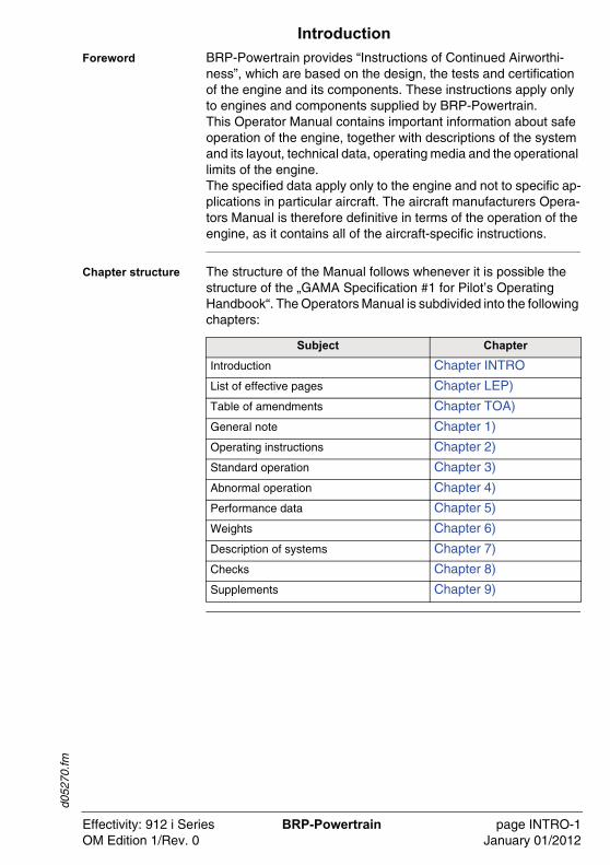
Foreword BRP-Powertrain provides “Instructions of Continued Airworthi-ness”, which are based on the design, the tests and certification of the engine and its components. These instructions apply only to engines and components supplied by BRP-Powertrain. This Operator Manual contains important information about safe operation of the engine, together with descriptions of the system and its layout, technical data, operating media and the operational limits of the engine.The specified data apply only to the engine and not to specific ap-plications in particular aircraft. The aircraft manufacturers Opera-tors Manual is therefore definitive in terms of the operation of the engine, as it contains all of the aircraft-specific instructions.
Chapter structure The structure of the Manual follows whenever it is possible the structure of the „GAMA Specification #1 for Pilot’s Operating Handbook“. The Operators Manual is subdivided into the following chapters:
Subject Chapter
Introduction Chapter INTRO
List of effective pages Chapter LEP)
Table of amendments Chapter TOA)
General note Chapter 1)
Operating instructions Chapter 2)
Standard operation Chapter 3)
Abnormal operation Chapter 4)
Performance data Chapter 5)
Weights Chapter 6)
Description of systems Chapter 7)
Checks Chapter 8)
Supplements Chapter 9)
Effectivity: 912 i Series BRP-Powertrain page INTRO-1OM Edition 1/Rev. 0 January 01/2012

d052
70.fm
NOTES
Effectivity: 912 i Series BRP-Powertrain page INTRO-2OM Edition 1/Rev. 0 January 01/2012
d056
92.fm
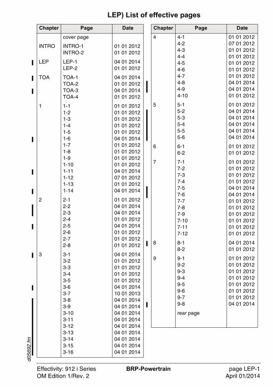
LEP) List of effective pages
Chapter Page Date
cover page
INTRO INTRO-1INTRO-2
01 01 201201 01 2012
LEP LEP-1LEP-2
04 01 201401 01 2012
TOA TOA-1TOA-2TOA-3TOA-4
04 01 201401 01 201204 01 201401 01 2012
1 1-11-21-31-41-51-61-71-81-91-101-111-121-131-14
01 01 201201 01 201201 01 201201 01 201201 01 201204 01 201401 01 201201 01 201201 01 201201 01 201204 01 201407 01 201201 01 201204 01 2014
2 2-12-22-32-42-52-62-72-8
01 01 201204 01 201404 01 201401 01 201204 01 201401 01 201201 01 201201 01 2012
3 3-13-23-33-43-53-63-73-83-93-103-113-123-133-143-153-16
04 01 201401 01 201201 01 201201 01 201201 01 201204 01 201410 01 201304 01 201404 01 201404 01 201404 01 201404 01 201404 01 201404 01 201404 01 201404 01 2014
4 4-14-24-34-44-54-64-74-84-94-10
01 01 201207 01 201201 01 201201 01 201201 01 201201 01 201201 01 201204 01 201404 01 201401 01 2012
5 5-15-25-35-45-55-6
01 01 201204 01 201404 01 201404 01 201404 01 201404 01 2014
6 6-16-2
01 01 201201 01 2012
7 7-17-27-37-47-57-67-77-87-97-107-117-12
01 01 201201 01 201201 01 201201 01 201204 01 201404 01 201401 01 201201 01 201201 01 201201 01 201201 01 201201 01 2012
8 8-18-2
04 01 201401 01 2012
9 9-19-29-39-49-59-69-79-8
01 01 201201 01 201201 01 201201 01 201201 01 201201 01 201201 01 201204 01 2014
rear page
Chapter Page Date
Effectivity: 912 i Series BRP-Powertrain page LEP-1OM Edition 1/Rev. 2 April 01/2014

d056
92.fm
NOTES
Effectivity: 912 i Series BRP-Powertrain page LEP-2OM Edition 1/Rev. 0 January 01/2012
d056
93.fm
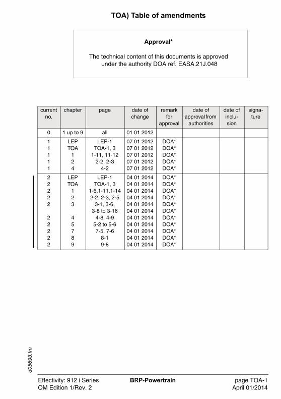
TOA) Table of amendments
Approval*
The technical content of this documents is approved under the authority DOA ref. EASA.21J.048
current no.
chapter page date of change
remark for
approval
date of approval from
authorities
date of inclu-sion
signa-ture
0 1 up to 9 all 01 01 2012
11111
LEPTOA
124
LEP-1TOA-1, 3
1-11, 11-122-2, 2-3
4-2
07 01 201207 01 201207 01 201207 01 201207 01 2012
DOA*DOA*DOA*DOA*DOA*
22222
22222
LEPTOA
123
45789
LEP-1TOA-1, 3
1-6,1-11,1-142-2, 2-3, 2-5
3-1, 3-6, 3-8 to 3-16
4-8, 4-95-2 to 5-67-5, 7-6
8-19-8
04 01 201404 01 201404 01 201404 01 201404 01 201404 01 201404 01 201404 01 201404 01 201404 01 201404 01 2014
DOA*DOA*DOA*DOA*DOA*DOA*DOA*DOA*DOA*DOA*DOA*
Effectivity: 912 i Series BRP-Powertrain page TOA-1OM Edition 1/Rev. 2 April 01/2014

d056
93.fm
NOTES
Effectivity: 912 i Series BRP-Powertrain page TOA-2OM Edition 1/Rev. 0 January 01/2012
d056
93.fm
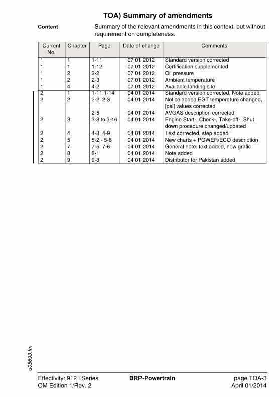
TOA) Summary of amendments
Content Summary of the relevant amendments in this context, but without requirement on completeness.
Current No.
Chapter Page Date of change Comments
11111
11224
1-111-122-22-34-2
07 01 201207 01 201207 01 201207 01 201207 01 2012
Standard version correctedCertification supplementedOil pressureAmbient temperatureAvailable landing site
22
2
22222
12
3
45789
1-11,1-142-2, 2-3
2-53-8 to 3-16
4-8, 4-95-2 - 5-67-5, 7-68-19-8
04 01 201404 01 2014
04 01 201404 01 2014
04 01 201404 01 201404 01 201404 01 201404 01 2014
Standard version corrected, Note addedNotice added,EGT temperature changed, [psi] values correctedAVGAS description correctedEngine Start-, Check-, Take-off-, Shut down procedure changed/updatedText corrected, step addedNew charts + POWER/ECO descriptionGeneral note: text added, new graficNote addedDistributor for Pakistan added
Effectivity: 912 i Series BRP-Powertrain page TOA-3OM Edition 1/Rev. 2 April 01/2014

d056
93.fm
NOTES
Effectivity: 912 i Series BRP-Powertrain page TOA-4OM Edition 1/Rev. 0 January 01/2012
d056
94.fm
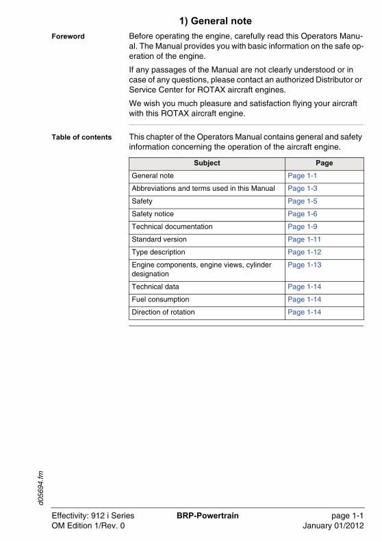
1) General note
Foreword Before operating the engine, carefully read this Operators Manu-al. The Manual provides you with basic information on the safe op-eration of the engine.
If any passages of the Manual are not clearly understood or in case of any questions, please contact an authorized Distributor or Service Center for ROTAX aircraft engines.
We wish you much pleasure and satisfaction flying your aircraft with this ROTAX aircraft engine.
Table of contents This chapter of the Operators Manual contains general and safety information concerning the operation of the aircraft engine.
Subject Page
General note Page 1-1
Abbreviations and terms used in this Manual Page 1-3
Safety Page 1-5
Safety notice Page 1-6
Technical documentation Page 1-9
Standard version Page 1-11
Type description Page 1-12
Engine components, engine views, cylinder designation
Page 1-13
Technical data Page 1-14
Fuel consumption Page 1-14
Direction of rotation Page 1-14
Effectivity: 912 i Series BRP-Powertrain page 1-1OM Edition 1/Rev. 0 January 01/2012
d056
94.fm
1.1) General note
Purpose The purpose of this Operators Manual is provided to familiarize the owner/user of this aircraft engine with basic operating instruc-tions and safety information.
Documentation For more detailed information regarding, maintenance, safety- or flight operation, consult the documentation provided by the aircraft manufacturer and/or dealer.
For additional information on engines, maintenance or parts, you can also contact your nearest authorized ROTAX-aircraft engine distributor (Chapter 9.2).
Engine serial num-ber
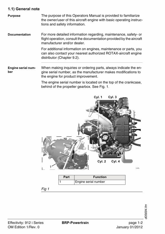
When making inquiries or ordering parts, always indicate the en-gine serial number, as the manufacturer makes modifications to the engine for product improvement.
The engine serial number is located on the top of the crankcase, behind of the propeller gearbox. See Fig. 1.
Fig 1
Part Function
1 Engine serial number
Cyl. 1 Cyl. 3
Cyl. 4Cyl. 2
Effectivity: 912 i Series BRP-Powertrain page 1-2OM Edition 1/Rev. 0 January 01/2012
d056
94.fm
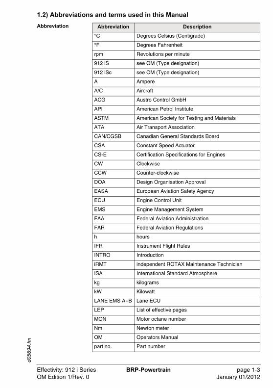
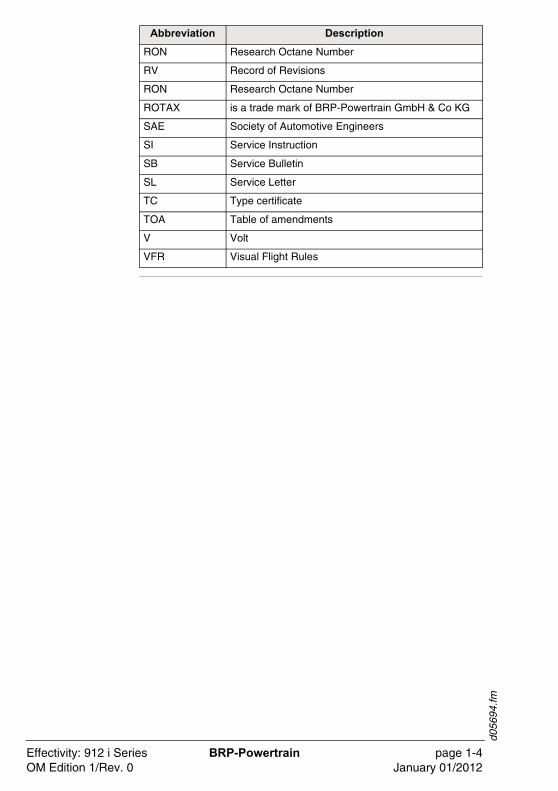
1.2) Abbreviations and terms used in this Manual
Abbreviation Abbreviation Description
°C Degrees Celsius (Centigrade)
°F Degrees Fahrenheit
rpm Revolutions per minute
912 iS see OM (Type designation)
912 iSc see OM (Type designation)
A Ampere
A/C Aircraft
ACG Austro Control GmbH
API American Petrol Institute
ASTM American Society for Testing and Materials
ATA Air Transport Association
CAN/CGSB Canadian General Standards Board
CSA Constant Speed Actuator
CS-E Certification Specifications for Engines
CW Clockwise
CCW Counter-clockwise
DOA Design Organisation Approval
EASA European Aviation Safety Agency
ECU Engine Control Unit
EMS Engine Management System
FAA Federal Aviation Administration
FAR Federal Aviation Regulations
h hours
IFR Instrument Flight Rules
INTRO Introduction
iRMT independent ROTAX Maintenance Technician
ISA International Standard Atmosphere
kg kilograms
kW Kilowatt
LANE EMS A+B Lane ECU
LEP List of effective pages
MON Motor octane number
Nm Newton meter
OM Operators Manual
part no. Part number
Effectivity: 912 i Series BRP-Powertrain page 1-3OM Edition 1/Rev. 0 January 01/2012
d056
94.fm
RON Research Octane Number
RV Record of Revisions
RON Research Octane Number
ROTAX is a trade mark of BRP-Powertrain GmbH & Co KG
SAE Society of Automotive Engineers
SI Service Instruction
SB Service Bulletin
SL Service Letter
TC Type certificate
TOA Table of amendments
V Volt
VFR Visual Flight Rules
Abbreviation Description
Effectivity: 912 i Series BRP-Powertrain page 1-4OM Edition 1/Rev. 0 January 01/2012
d056
94.fm
1.3) Safety
General note Although the reading of such information does not eliminate the hazard, understanding the information will promote its correct use. Always use common workshop safety practice.The information and components-/system descriptions contained in this Manual are correct at the time of publication. BRP-Powertrain, however, maintains a policy of continuous im-provement of its products without imposing upon itself any obliga-tion to install them on its products previously manufactured.
Revision BRP-Powertrain reserves the right at any time, and without incur-ring obligation, to remove, replace or discontinue any design, specification, feature or otherwise.
Measure Specifications are given in the SI metric system with the USA equivalent in parenthesis.
Translation This document has been translated from German language and the original German text shall be deemed authoritative.
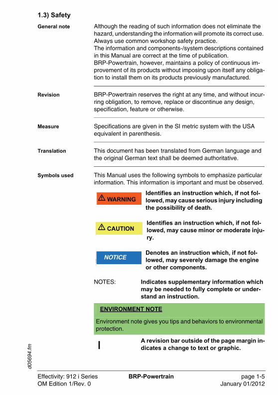
Symbols used This Manual uses the following symbols to emphasize particular information. This information is important and must be observed.
NOTES: Indicates supplementary information which may be needed to fully complete or under-stand an instruction.
A revision bar outside of the page margin in-dicates a change to text or graphic.
�WARNU� WARNINGIdentifies an instruction which, if not fol-lowed, may cause serious injury including the possibility of death.
�WARNUN� CAUTIONIdentifies an instruction which, if not fol-lowed, may cause minor or moderate inju-ry.
�WARNUNGNOTICEDenotes an instruction which, if not fol-lowed, may severely damage the engine or other components.
ENVIRONMENT NOTE
Environment note gives you tips and behaviors to environmentalprotection.
Effectivity: 912 i Series BRP-Powertrain page 1-5OM Edition 1/Rev. 0 January 01/2012
d056
94.fm
1.4) Safety notice
Normal use z
- This engine is not suitable for acrobatics (inverted flight, etc.).
- This engine shall not be used on rotorcrafts with an in-flight driven rotor (e.g. helicopters).
- It should be clearly understood that the choice, selection and use of this particular engine on any aircraft is at the sole dis-cretion and responsibility of the aircraft manufacturer, assem-bler and owner/user.
- Due to the varying designs, equipment and types of aircraft, BRP-Powertrain grants no warranty or representation on the suitability of its engine’s use on any particular aircraft. Further, BRP-Powertrain grants no warranty or representation of this engine’s suitability with any other part, components or system which may be selected by the aircraft manufacturer, assemb-ler or user for aircraft application.
- Certain areas, altitudes and conditions present greater risk than others. The engine may require humidity or dust/sand preventative equipment, or additional maintenance may be re-quired.
- You should be aware that any engine may seize or stall at any time. This could lead to a crash landing and possible severe injury or death. For this reason, we recommend strict compli-ance with the maintenance and operation and any additional information which may be given to you by your dealer.
�WARNU� WARNINGNon-compliance can result in serious injuries or death!Never fly the aircraft equipped with this en-gine at locations, airspeeds, altitudes, or oth-er circumstances from which a successful no-power landing cannot be made, after sudden engine stoppage.
�WARNU� WARNINGNon-compliance can result in serious injuries or death!For each use of VFR or IFR in an aircraft the applicable requirements and other existing regulations must be adhered.
Effectivity: 912 i Series BRP-Powertrain page 1-6OM Edition 1/Rev. 2 April 01/2014
d056
94.fm
Training - Whether you are a qualified pilot or a novice, complete know-ledge of the aircraft, its controls and operation is mandatory before venturing solo. Flying any type of aircraft involves a cer-tain amount of risk. Be informed and prepared for any situation or hazard associated with flying.
- A recognized training program and continued education for pi-loting an aircraft is absolutely necessary for all aircraft pilots. Make sure you also obtain as much information as possible about your aircraft, its maintenance and operation from your dealer.
- Engine-specific training courses are authorized by the distrib-utors according to manufacturer specifications (iRMT).
Regulation - Respect all government or local rules pertaining to flight ope-ration in your flying area. Fly only when and where conditions, topography, and airspeeds are safest.
- Consult your aircraft dealer or manufacturer and obtain the ne-cessary information, especially before flying in new areas.
Instrumentation - Select and use proper aircraft instrumentation. This instru-mentation is not included with the ROTAX engine package. Only approved instrumentation may be installed.
Engine log book - Keep an engine log book and respect engine and aircraft maintenance schedules. Keep the engine in top operating condition at all times. Do not operate any aircraft which is not properly maintained or has engine operating irregularities which have not been corrected.
Maintenance (iRMT)
- Before flight, ensure that all engine controls are operative. Make sure all controls can be easily reached in case of an emergency.
- Since special tools and equipment may be required, engine servicing should only be performed by an authorized ROTAX engine dealer. BRP-Powertrain requires that any service be carried out and verified by a technician that has a current iRMT rating.
Effectivity: 912 i Series BRP-Powertrain page 1-7OM Edition 1/Rev. 0 January 01/2012
d056
94.fm
- When in storage protect the engine and fuel system from con-tamination and exposure.
Engine run - Never operate the engine without sufficient quantities of oper-ating fluids (oil, coolant, fuel).
- Never exceed the maximum permitted operational limits.
- In the interest of safety, the aircraft must not be left unattended while the engine is running.
- To eliminate possible injury or damage, ensure any loose equipment or tools are properly secured before starting the en-gine.
- Allow the engine to cool at idle for several minutes before turn-ing off the engine.
Vacuum pump - This engine may be equipped with a vacuum pump. The safety warning accompanying the vacuum pump must be given to the owner/operator of the aircraft into which the vacuum pump is installed.
Governor - This engine may be equipped with a governor. The safety warning accompanying the governor must be given to the owner/operator of the aircraft into which the governor is in-stalled.
Effectivity: 912 i Series BRP-Powertrain page 1-8OM Edition 1/Rev. 0 January 01/2012
d056
94.fm
1.5) Technical documentation
General note These documents form the instructions ensuring continued air-worthiness of ROTAX aircraft engines.The information contained is based on data and experience that are considered applicable for skilled mechanics under normal conditions.Due to the fast technical progress and fulfilment of particular spec-ifications of the customers it may occur that existing laws, safety prescriptions, constructional and operational regulations cannot be transferred completely to the object bought, in particular for special constructions, or may not be sufficient.
Documentation - Installation Manual
- Operators Manual
- Maintenance Manual (Line and Heavy Maintenance)
- Overhaul Manual
- Illustrated Parts Catalog
- Alert Service Bulletins
- Service Bulletins
- Service Instructions
- Service Letters
Status The status of Manuals can be determined with the aid of the table of amendments. The first column indicates the revision state. This figure should be compared with the revision provided on ROTAX-Aircraft Engines Website: www.FLYROTAX.com.
Amendments and current versions can be downloaded free of change.
Replacement pag-es
Furthermore the Manual is constructed in such a way that single pages can be replaced instead of the complete document. The list of effective pages is given in the chapter LEP. The particular edi-tion and revision number is given on the footer of each page.
Reference Any reference to a document refers to the latest edition issued by BRP-Powertrain if not stated otherwise.
Effectivity: 912 i Series BRP-Powertrain page 1-9OM Edition 1/Rev. 0 January 01/2012
d056
94.fm
Illustrationen The illustrations in this Manual are mere sketches and show a typ-ical arrangement. They may not represent the actual part in all its details but depict parts of the same or similar function. Therefore deduction of dimensions or other details from illustrations is not permitted.
NOTE: The Illustrations in this Manual are stored in a graphic data base system and are provided with a consecutive irrelevant number.
This number (e.g. 00277) is of no significance for the content.
Effectivity: 912 i Series BRP-Powertrain page 1-10OM Edition 1/Rev. 0 January 01/2012
d056
94.fm
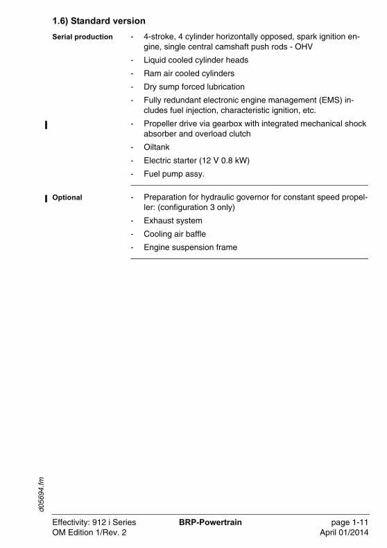
1.6) Standard version
Serial production - 4-stroke, 4 cylinder horizontally opposed, spark ignition en-gine, single central camshaft push rods - OHV
- Liquid cooled cylinder heads
- Ram air cooled cylinders
- Dry sump forced lubrication
- Fully redundant electronic engine management (EMS) in-cludes fuel injection, characteristic ignition, etc.
- Propeller drive via gearbox with integrated mechanical shock absorber and overload clutch
- Oiltank
- Electric starter (12 V 0.8 kW)
- Fuel pump assy.
Optional - Preparation for hydraulic governor for constant speed propel-ler: (configuration 3 only)
- Exhaust system
- Cooling air baffle
- Engine suspension frame
Effectivity: 912 i Series BRP-Powertrain page 1-11OM Edition 1/Rev. 2 April 01/2014
d056
94.fm
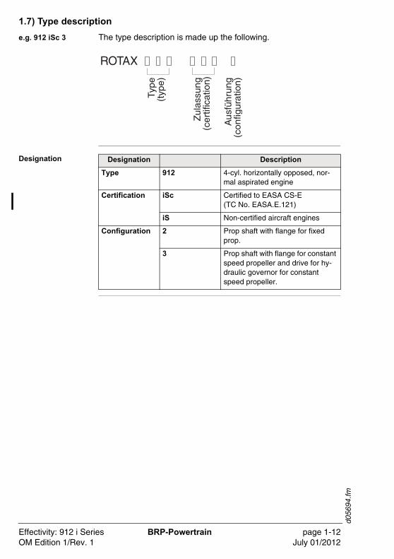
1.7) Type description
e.g. 912 iSc 3 The type description is made up the following.
DesignationTy
pe(t
ype)
Zul
assu
ng(c
ertif
icat
ion)
Aus
führ
ung
(con
figur
atio
n)
ROTAX
Designation Description
Type 912 4-cyl. horizontally opposed, nor-mal aspirated engine
Certification iSc Certified to EASA CS-E (TC No. EASA.E.121)
iS Non-certified aircraft engines
Configuration 2 Prop shaft with flange for fixed prop.
3 Prop shaft with flange for constant speed propeller and drive for hy-draulic governor for constant speed propeller.
Effectivity: 912 i Series BRP-Powertrain page 1-12OM Edition 1/Rev. 1 July 01/2012
d056
94.fm
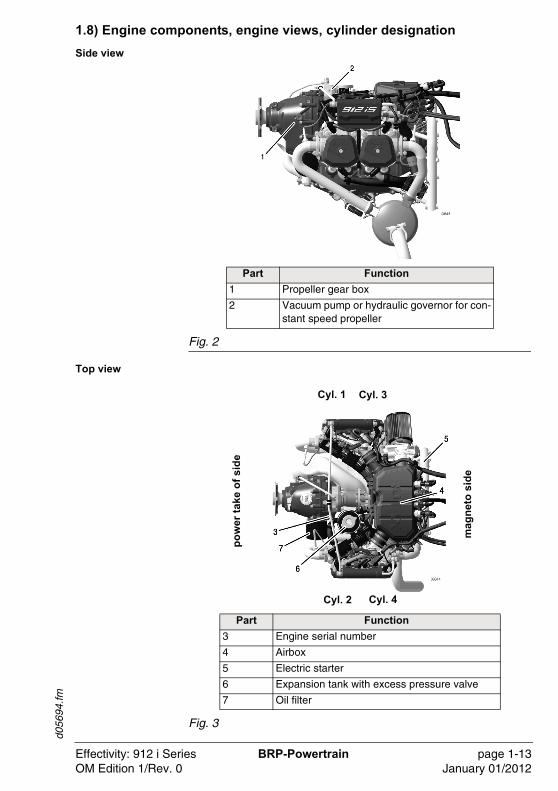
1.8) Engine components, engine views, cylinder designation
Side view
Fig. 2
Top view
Fig. 3
Part Function
1 Propeller gear box
2 Vacuum pump or hydraulic governor for con-stant speed propeller
Part Function
3 Engine serial number
4 Airbox
5 Electric starter
6 Expansion tank with excess pressure valve
7 Oil filter
Cyl. 3Cyl. 1
Cyl. 2 Cyl. 4
mag
net
o s
ide
po
wer
tak
e o
f si
de
Effectivity: 912 i Series BRP-Powertrain page 1-13OM Edition 1/Rev. 0 January 01/2012
d056
94.fm
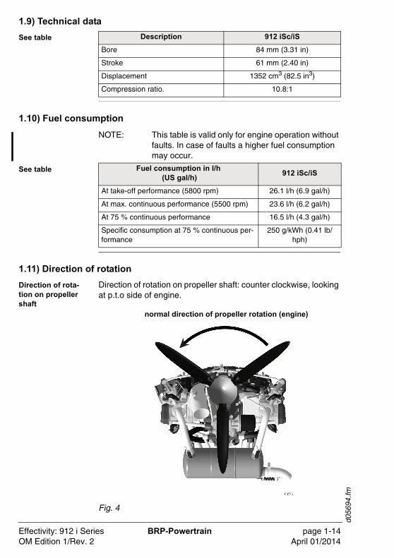
1.9) Technical data
See table
1.10) Fuel consumption
NOTE: This table is valid only for engine operation without faults. In case of faults a higher fuel consumption may occur.
See table
1.11) Direction of rotation
Direction of rota-tion on propeller shaft
Direction of rotation on propeller shaft: counter clockwise, looking at p.t.o side of engine.
Fig. 4
Description 912 iSc/iS
Bore 84 mm (3.31 in)
Stroke 61 mm (2.40 in)
Displacement 1352 cm3 (82.5 in3)
Compression ratio. 10.8:1
Fuel consumption in l/h (US gal/h)
912 iSc/iS
At take-off performance (5800 rpm) 26.1 l/h (6.9 gal/h)
At max. continuous performance (5500 rpm) 23.6 l/h (6.2 gal/h)
At 75 % continuous performance 16.5 l/h (4.3 gal/h)
Specific consumption at 75 % continuous per-formance
250 g/kWh (0.41 lb/hph)
normal direction of propeller rotation (engine)
Effectivity: 912 i Series BRP-Powertrain page 1-14OM Edition 1/Rev. 2 April 01/2014
d056
95.fm
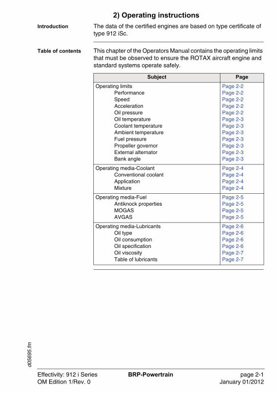
2) Operating instructions
Introduction The data of the certified engines are based on type certificate of type 912 iSc.
Table of contents This chapter of the Operators Manual contains the operating limits that must be observed to ensure the ROTAX aircraft engine and standard systems operate safely.
Subject Page
Operating limitsPerformanceSpeedAccelerationOil pressureOil temperatureCoolant temperatureAmbient temperatureFuel pressurePropeller governorExternal alternatorBank angle
Page 2-2Page 2-2Page 2-2Page 2-2Page 2-2Page 2-3Page 2-3Page 2-3Page 2-3Page 2-3Page 2-3Page 2-3
Operating media-CoolantConventional coolantApplicationMixture
Page 2-4Page 2-4Page 2-4Page 2-4
Operating media-FuelAntiknock propertiesMOGASAVGAS
Page 2-5Page 2-5Page 2-5Page 2-5
Operating media-LubricantsOil typeOil consumptionOil specificationOil viscosityTable of lubricants
Page 2-6Page 2-6Page 2-6Page 2-6Page 2-7Page 2-7
Effectivity: 912 i Series BRP-Powertrain page 2-1OM Edition 1/Rev. 0 January 01/2012
d056
95.fm
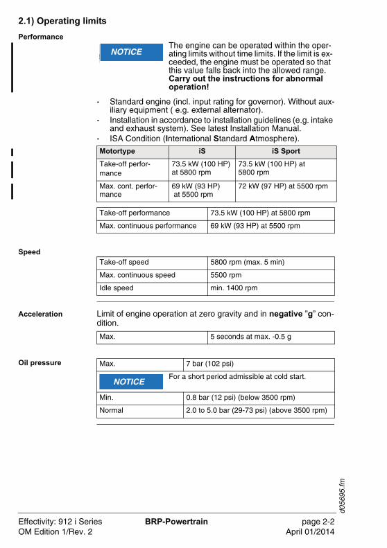
2.1) Operating limits
Performance
- Standard engine (incl. input rating for governor). Without aux-iliary equipment ( e.g. external alternator).
- Installation in accordance to installation guidelines (e.g. intake and exhaust system). See latest Installation Manual.
- ISA Condition (International Standard Atmosphere).
Speed
Acceleration Limit of engine operation at zero gravity and in negative ”g” con-dition.
Oil pressure
�WARNUNGNOTICEThe engine can be operated within the oper-ating limits without time limits. If the limit is ex-ceeded, the engine must be operated so that this value falls back into the allowed range. Carry out the instructions for abnormal operation!
Motortype iS iS Sport
Take-off perfor-mance
73.5 kW (100 HP) at 5800 rpm
73.5 kW (100 HP) at 5800 rpm
Max. cont. perfor-mance
69 kW (93 HP) at 5500 rpm
72 kW (97 HP) at 5500 rpm
Take-off performance 73.5 kW (100 HP) at 5800 rpm
Max. continuous performance 69 kW (93 HP) at 5500 rpm
Take-off speed 5800 rpm (max. 5 min)
Max. continuous speed 5500 rpm
Idle speed min. 1400 rpm
Max. 5 seconds at max. -0.5 g
Max. 7 bar (102 psi)
For a short period admissible at cold start.
Min. 0.8 bar (12 psi) (below 3500 rpm)
Normal 2.0 to 5.0 bar (29-73 psi) (above 3500 rpm)
NOTICE
Effectivity: 912 i Series BRP-Powertrain page 2-2OM Edition 1/Rev. 2 April 01/2014
d056
95.fm
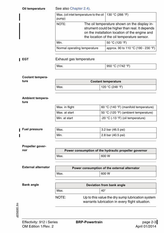
Oil temperature See also Chapter 2.4).
EGT Exhaust gas temperature
Coolant tempera-ture
Ambient tempera-ture
Fuel pressure
Propeller gover-nor
External alternator
Bank angle
NOTE: Up to this value the dry sump lubrication system warrants lubrication in every flight situation.
Max. (oil inlet temperature to the oil pump)
130 °C (266 °F)
NOTE: The oil temperature shown on the display in-strument could be higher than real. It depends on the installation location of the engine and the location of the oil temperature sensor.
Min. 50 °C (120 °F)
Normal operating temperature approx. 90 to 110 °C (190 - 230 °F)
Max. 950 °C (1742 °F)
Coolant temperature
Max. 120 °C (248 °F)
Max. in flight 60 °C (140 °F) (manifold temperature)
Max. at start 50 °C (120 °F) (ambient temperature)
Min. at start -20 °C (-13 °F) (oil temperature)
Max. 3.2 bar (46.5 psi)
Min. 2.8 bar (40.5 psi)
Power consumption of the hydraulic propeller governor
Max. 600 W
Power consumption of the external alternator
Max. 600 W
Deviation from bank angle
Max. 40°
Effectivity: 912 i Series BRP-Powertrain page 2-3OM Edition 1/Rev. 2 April 01/2014
d056
95.fm
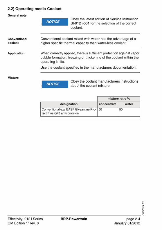
2.2) Operating media-Coolant
General note
Conventional coolant
Conventional coolant mixed with water has the advantage of a higher specific thermal capacity than water-less coolant.
Application When correctly applied, there is sufficient protection against vapor bubble formation, freezing or thickening of the coolant within the operating limits.
Use the coolant specified in the manufacturers documentation.
Mixture
�WARNUNGNOTICEObey the latest edition of Service Instruction SI-912 i-001 for the selection of the correct coolant.
�WARNUNGNOTICEObey the coolant manufacturers instructions about the coolant mixture.
mixture ratio %
designation concentrate water
Conventional e.g. BASF Glysantine Pro-tect Plus G48 anticorrosion
50 50
Effectivity: 912 i Series BRP-Powertrain page 2-4OM Edition 1/Rev. 0 January 01/2012
d056
95.fm
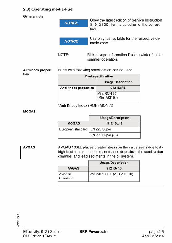
2.3) Operating media-Fuel
General note
NOTE: Risk of vapour formation if using winter fuel for summer operation.
Antiknock proper-ties
Fuels with following specification can be used:
*Anti Knock Index (RON+MON)/2
MOGAS
AVGAS AVGAS 100LL places greater stress on the valve seats due to its high lead content and forms increased deposits in the combustion chamber and lead sediments in the oil system.
�WARNUNGNOTICEObey the latest edition of Service Instruction SI-912 i-001 for the selection of the correct fuel.
�WARNUNGNOTICEUse only fuel suitable for the respective cli-matic zone.
Fuel specification
Usage/Description
Anti knock properties 912 iSc/iS
Min. RON 95(Min. AKI* 91)
Usage/Description
MOGAS 912 iSc/iS
European standard EN 228 Super
EN 228 Super plus
Usage/Description
AVGAS 912 iSc/iS
Aviation Standard
AVGAS 100 LL (ASTM D910)
Effectivity: 912 i Series BRP-Powertrain page 2-5OM Edition 1/Rev. 2 April 01/2014
d056
95.fm
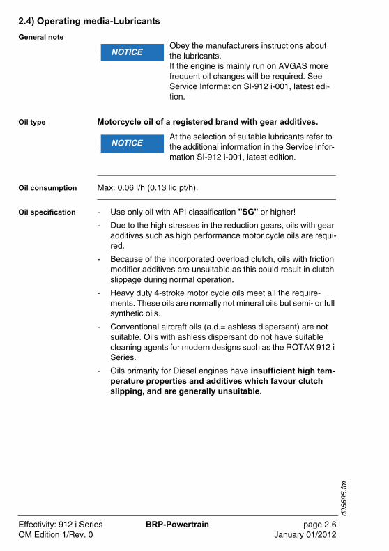
2.4) Operating media-Lubricants
General note
Oil type Motorcycle oil of a registered brand with gear additives.
Oil consumption Max. 0.06 l/h (0.13 liq pt/h).
Oil specification - Use only oil with API classification "SG" or higher!
- Due to the high stresses in the reduction gears, oils with gear additives such as high performance motor cycle oils are requi-red.
- Because of the incorporated overload clutch, oils with friction modifier additives are unsuitable as this could result in clutch slippage during normal operation.
- Heavy duty 4-stroke motor cycle oils meet all the require-ments. These oils are normally not mineral oils but semi- or full synthetic oils.
- Conventional aircraft oils (a.d.= ashless dispersant) are not suitable. Oils with ashless dispersant do not have suitable cleaning agents for modern designs such as the ROTAX 912 i Series.
- Oils primarity for Diesel engines have insufficient high tem-perature properties and additives which favour clutch slipping, and are generally unsuitable.
�WARNUNGNOTICEObey the manufacturers instructions about the lubricants.If the engine is mainly run on AVGAS more frequent oil changes will be required. See Service Information SI-912 i-001, latest edi-tion.
�WARNUNGNOTICEAt the selection of suitable lubricants refer to the additional information in the Service Infor-mation SI-912 i-001, latest edition.
Effectivity: 912 i Series BRP-Powertrain page 2-6OM Edition 1/Rev. 0 January 01/2012
d056
95.fm
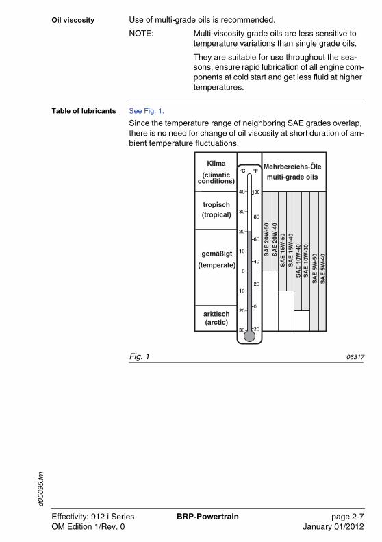
Oil viscosity Use of multi-grade oils is recommended.
NOTE: Multi-viscosity grade oils are less sensitive to temperature variations than single grade oils.
They are suitable for use throughout the sea-sons, ensure rapid lubrication of all engine com-ponents at cold start and get less fluid at higher temperatures.
Table of lubricants See Fig. 1.
Since the temperature range of neighboring SAE grades overlap, there is no need for change of oil viscosity at short duration of am-bient temperature fluctuations.
Fig. 1 06317
Effectivity: 912 i Series BRP-Powertrain page 2-7OM Edition 1/Rev. 0 January 01/2012

d056
95.fm
NOTES
Effectivity: 912 i Series BRP-Powertrain page 2-8OM Edition 1/Rev. 0 January 01/2012
d056
96.fm
3) Standard operation
Introduction To warrant reliability and efficiency of the engine, meet and care-fully observe all the operating and maintenance instructions.
Table of content This chapter of the Operators Manual contains expanded operat-ing and maintenance instructions.
Subject Page
Daily checksCoolant levelMech./electronic componentsThrottle valveExhaust systemSensors/wiring harness
Page 3-2Page 3-3Page 3-5Page 3-5Page 3-5Page 3-5
Before engine start Page 3-6
Pre-flight checksOperating mediaOil levelOil level (oil dipstick)
Page 3-6Page 3-6Page 3-6Page 3-7
Engine startEngine start
Page 3-8Page 3-8
Prior to take-offWarming up period
Page 3-10Page 3-11
Holding point controlGround testIgnition checkCheck the power outputPropeller governor
Page 3-11Page 3-11Page 3-11Page 3-12Page 3-13
Take-offClimb
Page 3-13Page 3-13
CruisingPerformanceOil temperature
Page 3-13Page 3-13Page 3-13
Engine shut-off Page 3-14
Cold weather operationCoolantLubricantCold startIcing due to water in fuel
Page 3-15Page 3-15Page 3-15Page 3-15Page 3-15
Effectivity: 912 i Series BRP-Powertrain page 3-1OM Edition 1/Rev. 2 April 01/2014
d056
96.fm
3.1) Daily checks
General note To warrant reliability and efficiency of the engine, meet and care-fully observe all the operating and maintenance instructions.
�WARNU� WARNINGRisk of burnings and scalds!Hot engine parts!Conduct checks on the cold engine only!
�WARNU� WARNINGNon-compliance can result in serious injuries or death!Ignition “OFF”Before moving the propeller switch off the ECU and secure the aircraft. The main switch (EMS-switch) has to be deactivated. If a key switch is used, then pull out the key.
�WARNUNGNOTICEIf established abnormalities (e.g. excessive resistance of the engine, noises etc.) inspec-tion in accordance with the relevant Mainte-nance Manual is necessary. Do not release the engine into service before rectification.
Effectivity: 912 i Series BRP-Powertrain page 3-2OM Edition 1/Rev. 0 January 01/2012
d056
96.fm
Coolant level
Expansion tank
Fig. 1
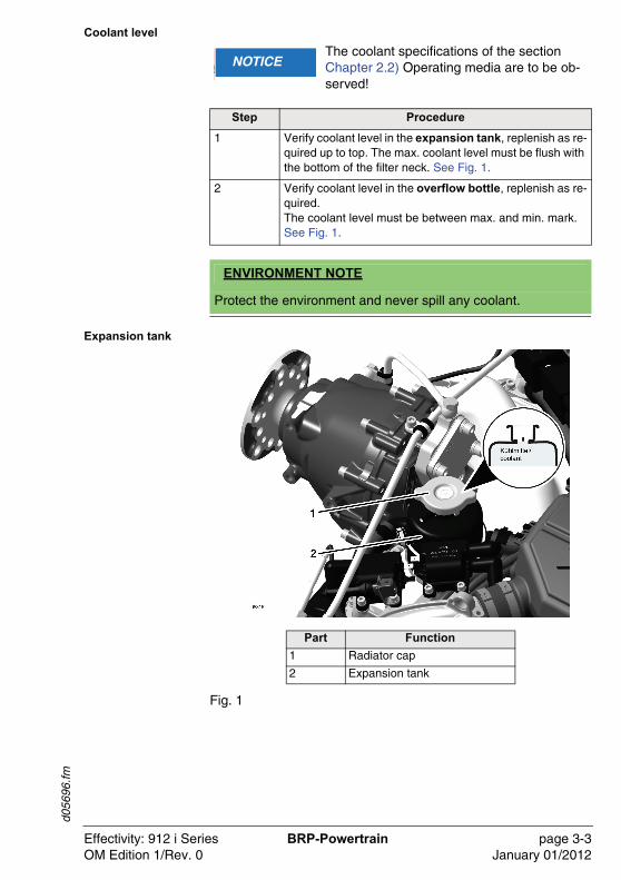
�WARNUNGNOTICEThe coolant specifications of the section Chapter 2.2) Operating media are to be ob-served!
Step Procedure
1 Verify coolant level in the expansion tank, replenish as re-quired up to top. The max. coolant level must be flush with the bottom of the filter neck. See Fig. 1.
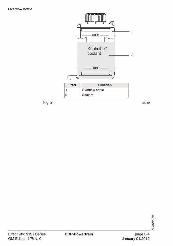
2 Verify coolant level in the overflow bottle, replenish as re-quired.The coolant level must be between max. and min. mark. See Fig. 1.
ENVIRONMENT NOTE
Protect the environment and never spill any coolant.
Part Function
1 Radiator cap
2 Expansion tank
Effectivity: 912 i Series BRP-Powertrain page 3-3OM Edition 1/Rev. 0 January 01/2012
d056
96.fm
Overflow bottle
Fig. 2 09150
Part Function
1 Overflow bottle
2 Coolant
Kühlmittel/coolant
1
2
Effectivity: 912 i Series BRP-Powertrain page 3-4OM Edition 1/Rev. 0 January 01/2012
d056
96.fm
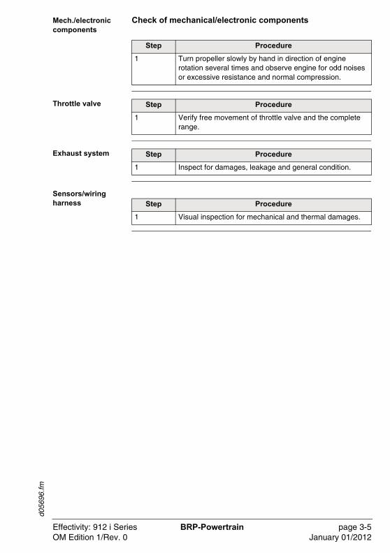
Mech./electronic components
Check of mechanical/electronic components
Throttle valve
Exhaust system
Sensors/wiring harness
Step Procedure
1 Turn propeller slowly by hand in direction of engine rotation several times and observe engine for odd noises or excessive resistance and normal compression.
Step Procedure
1 Verify free movement of throttle valve and the complete range.
Step Procedure
1 Inspect for damages, leakage and general condition.
Step Procedure
1 Visual inspection for mechanical and thermal damages.
Effectivity: 912 i Series BRP-Powertrain page 3-5OM Edition 1/Rev. 0 January 01/2012
d056
96.fm
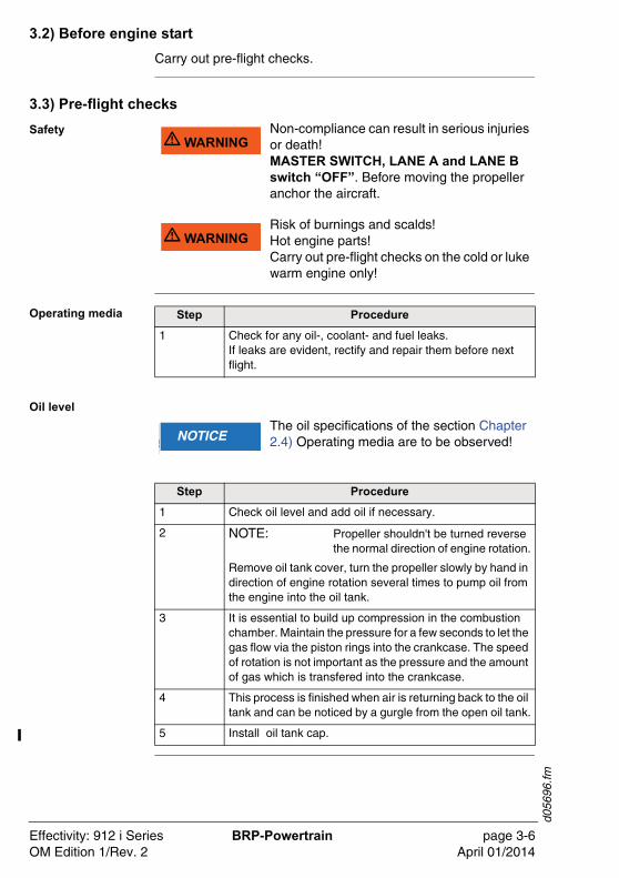
3.2) Before engine start
Carry out pre-flight checks.
3.3) Pre-flight checks
Safety
Operating media
Oil level
�WARNU� WARNINGNon-compliance can result in serious injuries or death!MASTER SWITCH, LANE A and LANE B switch “OFF”. Before moving the propeller anchor the aircraft.
�WARNU� WARNINGRisk of burnings and scalds!Hot engine parts!Carry out pre-flight checks on the cold or luke warm engine only!
Step Procedure
1 Check for any oil-, coolant- and fuel leaks.If leaks are evident, rectify and repair them before next flight.
�WARNUNGNOTICEThe oil specifications of the section Chapter 2.4) Operating media are to be observed!
Step Procedure
1 Check oil level and add oil if necessary.
2 NOTE: Propeller shouldn't be turned reverse the normal direction of engine rotation.
Remove oil tank cover, turn the propeller slowly by hand in direction of engine rotation several times to pump oil from the engine into the oil tank.
3 It is essential to build up compression in the combustion chamber. Maintain the pressure for a few seconds to let the gas flow via the piston rings into the crankcase. The speed of rotation is not important as the pressure and the amount of gas which is transfered into the crankcase.
4 This process is finished when air is returning back to the oil tank and can be noticed by a gurgle from the open oil tank.
5 Install oil tank cap.
Effectivity: 912 i Series BRP-Powertrain page 3-6OM Edition 1/Rev. 2 April 01/2014
d056
96.fm
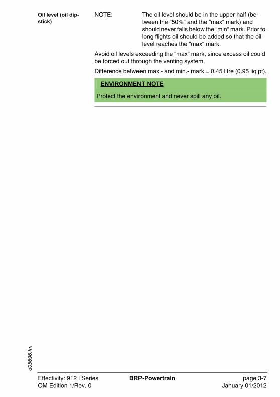
Oil level (oil dip-stick)
NOTE: The oil level should be in the upper half (be-tween the “50%“ and the “max“ mark) and should never falls below the “min“ mark. Prior to long flights oil should be added so that the oil level reaches the “max“ mark.
Avoid oil levels exceeding the “max“ mark, since excess oil could be forced out through the venting system.
Difference between max.- and min.- mark = 0.45 litre (0.95 liq pt).
ENVIRONMENT NOTE
Protect the environment and never spill any oil.
Effectivity: 912 i Series BRP-Powertrain page 3-7OM Edition 1/Rev. 0 January 01/2012
d056
96.fm
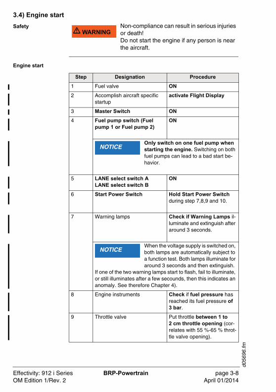
3.4) Engine start
Safety
Engine start
�WARNU� WARNINGNon-compliance can result in serious injuries or death!Do not start the engine if any person is near the aircraft.
Step Designation Procedure
1 Fuel valve ON
2 Accomplish aircraft specific startup
activate Flight Display
3 Master Switch ON
4 Fuel pump switch (Fuel pump 1 or Fuel pump 2)
ON
Only switch on one fuel pump when starting the engine. Switching on both fuel pumps can lead to a bad start be-havior.
5 LANE select switch ALANE select switch B
ON
6 Start Power Switch Hold Start Power Switch during step 7,8,9 and 10.
7 Warning lamps Check if Warning Lamps il-luminate and extinguish after around 3 seconds.
When the voltage supply is switched on, both lamps are automatically subject to a function test. Both lamps illuminate for around 3 seconds and then extinguish.
If one of the two warning lamps start to flash, fail to illuminate, or still illuminates after a few secounds, then this indicates an anomaly. See therefore Chapter 4).
8 Engine instruments Check if fuel pressure has reached its fuel pressure of 3 bar.
9 Throttle valve Put throttle between 1 to 2 cm throttle opening (cor-relates with 55 %-65 % throt-tle valve opening).
NOTICE
NOTICE
Effectivity: 912 i Series BRP-Powertrain page 3-8OM Edition 1/Rev. 2 April 01/2014
d056
96.fm
For more and detailed information on the throttle opening during engine start up see the diagram. See Fig. 3
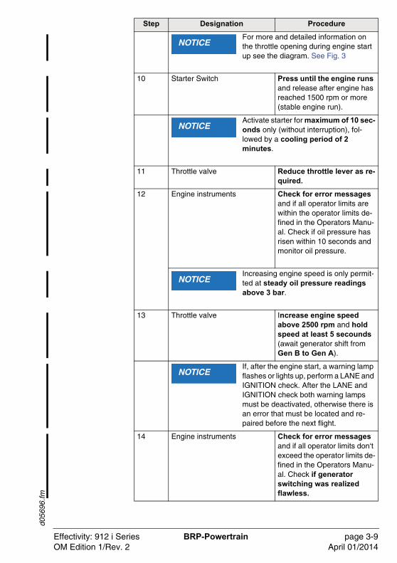
10 Starter Switch Press until the engine runs and release after engine has reached 1500 rpm or more (stable engine run).
Activate starter for maximum of 10 sec-onds only (without interruption), fol-lowed by a cooling period of 2 minutes.
11 Throttle valve Reduce throttle lever as re-quired.
12 Engine instruments Check for error messages and if all operator limits are within the operator limits de-fined in the Operators Manu-al. Check if oil pressure has risen within 10 seconds and monitor oil pressure.
Increasing engine speed is only permit-ted at steady oil pressure readings above 3 bar.
13 Throttle valve Increase engine speed above 2500 rpm and hold speed at least 5 secounds (await generator shift from Gen B to Gen A).
If, after the engine start, a warning lamp flashes or lights up, perform a LANE and IGNITION check. After the LANE and IGNITION check both warning lamps must be deactivated, otherwise there is an error that must be located and re-paired before the next flight.
14 Engine instruments Check for error messages and if all operator limits don‘t exceed the operator limits de-fined in the Operators Manu-al. Check if generator switching was realized flawless.
Step Designation Procedure
NOTICE
NOTICE
NOTICE
NOTICE
Effectivity: 912 i Series BRP-Powertrain page 3-9OM Edition 1/Rev. 2 April 01/2014
d056
96.fm
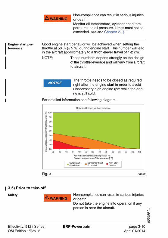
Engine start per-formance
Good engine start behavior will be achieved when setting the throttle at 50 % (± 5 %) during engine start. This number will lead in the aircraft approximately to a throttlelever travel of 1-2 cm.
NOTE: These numbers depend strongly on the design of the throttle leverage and will vary from aircraft to aircraft.
For detailed information see following diagram.
Fig. 3 08252
3.5) Prior to take-off
Safety
�WARNU� WARNINGNon-compliance can result in serious injuries or death!Monitor oil temperature, cylinder head tem-perature and oil pressure. Limits must not be exceeded. See also Chapter 2.1).
�WARNUNGNOTICEThe throttle needs to be closed as required right after the engine start in order to avoid unnecessary high engine rpm while the engi-ne is still cold.
�WARNU� WARNINGNon-compliance can result in serious injuries or death!Do not take the engine into operation if any person is near the aircraft.
Effectivity: 912 i Series BRP-Powertrain page 3-10OM Edition 1/Rev. 2 April 01/2014
d056
96.fm
Warming up peri-od
3.6) Holding point control
Ground test
Ignition check Check the double ignition
Check the two ignition circuits at 4000 rpm (approx. 1700 rpm pro-peller).
LANE and Ignition Check:
Step Procedure
1 Start warming up period at approx. 2000 rpm for approx. 2 minutes.
2 Continue at 2500 rpm, duration depending on ambient temperature, until oil temperature reaches 50 °C (120 °F).
3 Check temperatures and pressures.
�WARNUNGNOTICEAfter a full-load ground test allow a short cool-ing run at idle speed to prevent vapour forma-tion in the cylinder head.
Step Procedure
1 Short full throttle ground test (consult Aircraft Operators Manual since engine speed depends on the propeller used).
�WARNUNGNOTICEIf the engine speed drops or any error mes-sages are present from the EMS then find out what the cause is and take corresponding ac-tion to rectify the problem.
Step Procedure
1 Rise engine speed up to 4000 rpm.
2 Turn “OFF“ LANE selector switch A. Observe the rev counter.
The speed drop may not exceed 180 rpm engine speed, which corresponds 75 rpm propeller speed.
3 Turn „ON“ LANE selector switch A.
4 Turn „OFF“ LANE selector switch B. Perform checks in same way as LANE A.
5 Turn “ON“ LANE selector switch B.
6 Reduce to idle speed.
7 Check power supply and minimum voltage of 12 V at each LANE.
NOTICE
Effectivity: 912 i Series BRP-Powertrain page 3-11OM Edition 1/Rev. 2 April 01/2014
d056
96.fm
NOTE: LANE A and LANE B have different sensor in-puts. During LANE and IGNITION check some sensor values are not displayed depending on the position of the LANE select switches.
Not available sensor values if LANE A = ON and LANE B = OFF:
- Coolant temperature
- Exhaust gas temperatures from cyl. 1-4
- Ambient temperature
- Ambient pressure
- Throttle lever position
Not available sensor values if LANE B = ON and LANE A = OFF:
- Oil temperature
- Oil pressure
Check of fuel pumps (fuel pump modules)
It must be ensured that both fuel pumps are working and no loss of power or uneven running by turning off a fuel pump occurs. The limits for fuel pressure must not be exceeded
Basic position for the Take-off, both fuel pumps „ON“.
Check the power output
To check the acceleration and available power, run the engine at full load with the aircraft stationary for a maximum of 10 seconds (take the idle speed from the Operators Manual of the aircraft, as it depends on the type of propeller being used).
Step Procedure
1 Set engine speed to 2000 rpm.
2 Turn auxiliary fuel pump OFF for 5 seconds.
3 Check fuel pressure, then turn auxiliary fuel pump ON.
4 Turn main fuel pump OFF for 5 seconds.
5 Check fuel pressure, then turn main fuel pump ON.
If the fuel pressure is not within the limits, the cause must be determined. The engine must not be put into service until the problem is rectified.
NOTICE
Effectivity: 912 i Series BRP-Powertrain page 3-12OM Edition 1/Rev. 2 April 01/2014
d056
96.fm
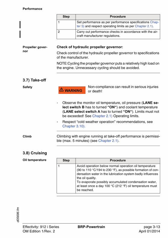
Performance
Propeller gover-nor
Check of hydraulic propeller governor:
Check control of the hydraulic propeller governor to specifications of the manufacturer.
NOTE:Cycling the propeller governor puts a relatively high load on the engine. Unnecessary cycling should be avoided.
3.7) Take-off
Safety
- Observe the monitor oil temperature, oil pressure (LANE se-lect switch B has to turned “ON“) and coolant temperature (LANE select switch A has to turned “ON“). Limits must not be exceeded! See Chapter 2.1) Operating limits.
- Respect “cold weather operation” recommendations, see Chapter 3.10).
Climb Climbing with engine running at take-off performance is permissi-ble (max. 5 minutes) (see Chapter 2.1).
3.8) Cruising
Oil temperature
Step Procedure
1 Set performance as per performance specifications Chap-ter 5) and respect operating limits as per Chapter 2.1).
2 Carry out performance checks in accordance with the air-craft manufacturer regulations.
�WARNU� WARNINGNon-compliance can result in serious injuries or death!
Step Procedure
1 Avoid operation below normal operation oil temperature (90 to 110 °C/194 to 230 °F), as possible formation of con-densation water in the lubrication system badly influences the oil quality.To evaporate possibly accumulated condensation water, at least once a day 100 °C (212 °F) oil temperature must be reached.
Effectivity: 912 i Series BRP-Powertrain page 3-13OM Edition 1/Rev. 2 April 01/2014
d056
96.fm
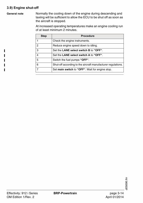
3.9) Engine shut-off
General note Normally the cooling down of the engine during descending and taxiing will be sufficient to allow the ECU to be shut off as soon as the aircraft is stopped.
At increased operating temperatures make an engine cooling run of at least minimum 2 minutes.
Step Procedure
1 Check the engine instruments.
2 Reduce engine speed down to idling.
3 Set the LANE select switch B to “OFF“.
4 Set the LANE select switch A to “OFF“.
5 Switch the fuel pumps “OFF“.
6 Shut-off according to the aircraft manufacturer regulations.
7 Set main switch to “OFF“. Wait for engine stop.
Effectivity: 912 i Series BRP-Powertrain page 3-14OM Edition 1/Rev. 2 April 01/2014
d056
96.fm
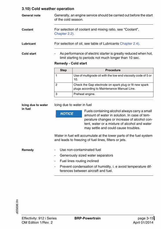
3.10) Cold weather operation
General note Generally, an engine service should be carried out before the start of the cold season.
Coolant For selection of coolant and mixing ratio, see "Coolant", Chapter 2.2).
Lubricant For selection of oil, see table of Lubricants Chapter 2.4).
Cold start - As performance of electric starter is greatly reduced when hot, limit starting to periods not much longer than 10 sec.
Remedy - Cold start
Icing due to water in fuel
Icing due to water in fuel
Water in fuel will accumulate at the lower parts of the fuel system and leads to freezing of fuel lines, filters or jets.
Remedy - Use non-contaminated fuel
- Generously sized water separators
- Fuel lines routing inclined
- Prevent condensation of humidity, i. e avoid temperature dif-ferences between aircraft and fuel.
Step Procedure
1 Use of multigrade oil with the low end viscosity code of 5 or 10.
2 Check the Gap electrode on spark plug or fit new spark plugs according to Maintenance Manual Line.
3 Preheat engine.
�WARNUNGNOTICEFuels containing alcohol always carry a small amount of water in solution. In case of tem-perature changes or increase of alcohol con-tent, water or a mixture of alcohol and water may settle and could cause troubles.
Effectivity: 912 i Series BRP-Powertrain page 3-15OM Edition 1/Rev. 2 April 01/2014

d056
96.fm
NOTES
Effectivity: 912 i Series BRP-Powertrain page 3-16OM Edition 1/Rev. 2 April 01/2014
d058
73.fm
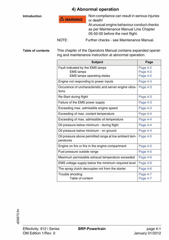
4) Abnormal operation
Introduction
NOTE: Further checks - see Maintenance Manual.
Table of contents This chapter of the Operators Manual contains expanded operat-ing and maintenance instruction at abnormal operation.
�WARNU� WARNINGNon-compliance can result in serious injuries or death!At unusual engine behaviour conduct checks as per Maintenance Manual Line Chapter 05-50-00 before the next flight.
Subject Page
Fault indicated by the EMS lampsEMS lampsEMS lamps operating states
Page 4-2Page 4-2Page 4-2
Engine not responding to power inputs Page 4-3
Occurence of uncharacteristic and server engine vibra-tions
Page 4-3
Re-Start during flight Page 4-3
Failure of the EMS power supply Page 4-3
Exceeding max. admissible engine speed Page 4-3
Exceeding of max. coolant temperature Page 4-4
Exceeding of max. admissible oil temperature Page 4-4
Oil pressure below minimum - during flight Page 4-4
Oil pressure below minimum - on ground Page 4-4
Oil pressure above permitted range at low ambient tem-peratures
Page 4-5
Engine on fire or fire in the engine compartment Page 4-5
Fuel pressure outside range Page 4-5
Maximum permissible exhaust temperature exceeded Page 4-6
EMS voltage supply below the minimum required level Page 4-6
The sprag clutch decouples not from the starter Page 4-6
Trouble shootingTable of content
Page 4-7Page 4-7
Effectivity: 912 i Series BRP-Powertrain page 4-1OM Edition 1/Rev. 0 January 01/2012
d058
73.fm
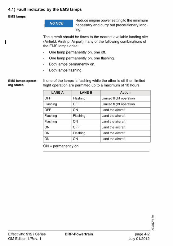
4.1) Fault indicated by the EMS lamps
EMS lamps
The aircraft should be flown to the nearest available landing site (Airfield, Airstrip, Airport) if any of the following combinations of the EMS lamps arise:
- One lamp permanently on, one off.
- One lamp permanently on, one flashing.
- Both lamps permanently on.
- Both lamps flashing.
EMS lamps operat-ing states
If one of the lamps is flashing while the other is off then limited flight operation are permitted up to a maximum of 10 hours.
ON = permanently on
�WARNUNGNOTICEReduce engine power setting to the minimum necessary and curry out precautionary land-ing.
LANE A LANE B Action
OFF Flashing Limited flight operation
Flashing OFF Limited flight operation
OFF ON Land the aircraft
Flashing Flashing Land the aircraft
Flashing ON Land the aircraft
ON OFF Land the aircraft
ON Flashing Land the aircraft
ON ON Land the aircraft
Effectivity: 912 i Series BRP-Powertrain page 4-2OM Edition 1/Rev. 1 July 01/2012
d058
73.fm
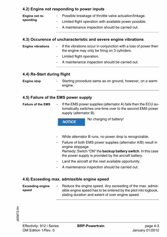
4.2) Engine not responding to power inputs
Engine not re-sponding
- Possible breakage of throttle valve actuation/linkage.
- Limited flight operation with available power possible.
- A maintenance inspection should be carried out.
4.3) Occurence of uncharacteristic and severe engine vibrations
Engine vibrations - If the vibrations occur in conjunction with a loss of power then the engine may only be firing on 3 cylinders.
- Limited flight operation.
- A maintenance inspection should be carried out.
4.4) Re-Start during flight
Engine stop - Starting procedure same as on ground, however, on a warm engine.
4.5) Failure of the EMS power supply
Failure of the EMS - If the EMS power supplies (alternator A) fails then the ECU au-tomatically switches one-time over to the second EMS power supply (alternator B).
- While alternator B runs, no power drop is recognizable.
- Failure of both EMS power supplies (alternator A/B) result in engine stoppage.Remedy: Switch “ON“ the backup battery switch. In this case the power supply is provided by the aircraft battery.
- Land the aircraft at the next available opportunity.
- A maintenance inspection should be carried out.
,
4.6) Exceeding max. admissible engine speed
Exceeding engine speed
- Reduce the engine speed. Any exceeding of the max. admis-sible engine speed has to be entered by the pilot into logbook, stating duration and extent of over engine speed.
�WARNUNGNOTICENo charging of battery!
Effectivity: 912 i Series BRP-Powertrain page 4-3OM Edition 1/Rev. 0 January 01/2012
d058
73.fm
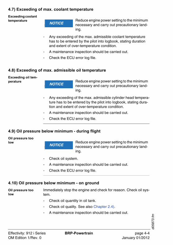
4.7) Exceeding of max. coolant temperature
Exceeding coolant temperature
- Any exceeding of the max. admissible coolant temperature has to be entered by the pilot into logbook, stating duration and extent of over-temperature condition.
- A maintenance inspection should be carried out.
- Check the ECU error log file.
4.8) Exceeding of max. admissible oil temperature
Exceeding oil tem-perature
- Any exceeding of the max. admissible cylinder head tempera-ture has to be entered by the pilot into logbook, stating dura-tion and extent of over-temperature condition.
- A maintenance inspection should be carried out.
- Check the ECU error log file.
4.9) Oil pressure below minimum - during flight
Oil pressure too low
- Check oil system.
- A maintenance inspection should be carried out.
- Check the ECU error log file.
4.10) Oil pressure below minimum - on ground
Oil pressure too low
Immediately stop the engine and check for reason. Check oil sys-tem.
- Check oil quantity in oil tank.
- Check oil quality. See also Chapter 2.4).
- A maintenance inspection should be carried out.
�WARNUNGNOTICEReduce engine power setting to the minimum necessary and carry out precautionary land-ing.
�WARNUNGNOTICEReduce engine power setting to the minimum necessary and carry out precautionary land-ing.
�WARNUNGNOTICEReduce engine power setting to the minimum necessary and carry out precautionary land-ing.
Effectivity: 912 i Series BRP-Powertrain page 4-4OM Edition 1/Rev. 0 January 01/2012
d058
73.fm
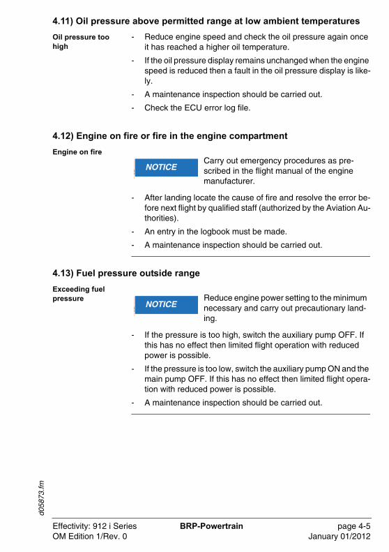
4.11) Oil pressure above permitted range at low ambient temperatures
Oil pressure too high
- Reduce engine speed and check the oil pressure again once it has reached a higher oil temperature.
- If the oil pressure display remains unchanged when the engine speed is reduced then a fault in the oil pressure display is like-ly.
- A maintenance inspection should be carried out.
- Check the ECU error log file.
4.12) Engine on fire or fire in the engine compartment
Engine on fire
- After landing locate the cause of fire and resolve the error be-fore next flight by qualified staff (authorized by the Aviation Au-thorities).
- An entry in the logbook must be made.
- A maintenance inspection should be carried out.
4.13) Fuel pressure outside range
Exceeding fuel pressure
- If the pressure is too high, switch the auxiliary pump OFF. If this has no effect then limited flight operation with reduced power is possible.
- If the pressure is too low, switch the auxiliary pump ON and the main pump OFF. If this has no effect then limited flight opera-tion with reduced power is possible.
- A maintenance inspection should be carried out.
�WARNUNGNOTICECarry out emergency procedures as pre-scribed in the flight manual of the engine manufacturer.
�WARNUNGNOTICEReduce engine power setting to the minimum necessary and carry out precautionary land-ing.
Effectivity: 912 i Series BRP-Powertrain page 4-5OM Edition 1/Rev. 0 January 01/2012
d058
73.fm
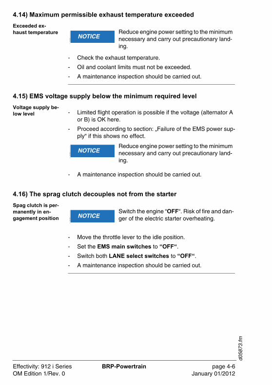
4.14) Maximum permissible exhaust temperature exceeded
Exceeded ex-haust temperature
- Check the exhaust temperature.
- Oil and coolant limits must not be exceeded.
- A maintenance inspection should be carried out.
4.15) EMS voltage supply below the minimum required level
Voltage supply be-low level - Limited flight operation is possible if the voltage (alternator A
or B) is OK here.
- Proceed according to section: „Failure of the EMS power sup-ply“ if this shows no effect.
- A maintenance inspection should be carried out.
4.16) The sprag clutch decouples not from the starter
Spag clutch is per-manently in en-gagement position
- Move the throttle lever to the idle position.
- Set the EMS main switches to “OFF“.
- Switch both LANE select switches to “OFF“.
- A maintenance inspection should be carried out.
�WARNUNGNOTICEReduce engine power setting to the minimum necessary and carry out precautionary land-ing.
�WARNUNGNOTICEReduce engine power setting to the minimum necessary and carry out precautionary land-ing.
�WARNUNGNOTICESwitch the engine “OFF“. Risk of fire and dan-ger of the electric starter overheating.
Effectivity: 912 i Series BRP-Powertrain page 4-6OM Edition 1/Rev. 0 January 01/2012
d058
73.fm
4.17) Trouble shooting
Introduction All checks in accordance with the Maintenance Manual (current issue/revision).
Table of content This chapter of the Operators Manual contains possible cause and remedy in case of trouble shooting.
�WARNU� WARNINGNon-compliance can result in serious injuries or death!Only qualified staff (authorized by the Avia-tion Authorities) trained on this particular en-gine, is allowed to carry out maintenance and repair work.
�WARNUNGNOTICEIf the following hints regarding remedy do not solve the problem, contact an authorized workshop. The engine must not be operated until the problem is rectified.
Subject Page
Starting problems Page 4-8
Engine run Page 4-8
Oil pressure Page 4-8
Oil level Page 4-9
Cold engine start Page 4-9
Effectivity: 912 i Series BRP-Powertrain page 4-7OM Edition 1/Rev. 0 January 01/2012
d058
73.fm
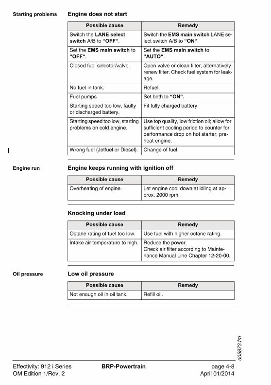
Starting problems Engine does not start
Engine run Engine keeps running with ignition off
Knocking under load
Oil pressure Low oil pressure
Possible cause Remedy
Switch the LANE select switch A/B to “OFF“.
Switch the EMS main switch LANE se-lect switch A/B to “ON“.
Set the EMS main switch to “OFF“.
Set the EMS main switch to “AUTO“.
Closed fuel selector/valve. Open valve or clean filter, alternatively renew filter. Check fuel system for leak-age.
No fuel in tank. Refuel.
Fuel pumps Set both to “ON“.
Starting speed too low, faulty or discharged battery.
Fit fully charged battery.
Starting speed too low, starting problems on cold engine.
Use top quality, low friction oil; allow for sufficient cooling period to counter for performance drop on hot starter; pre-heat engine.
Wrong fuel (Jetfuel or Diesel). Change of fuel.
Possible cause Remedy
Overheating of engine. Let engine cool down at idling at ap-prox. 2000 rpm.
Possible cause Remedy
Octane rating of fuel too low. Use fuel with higher octane rating.
Intake air temperature to high. Reduce the power.Check air filter according to Mainte-nance Manual Line Chapter 12-20-00.
Possible cause Remedy
Not enough oil in oil tank. Refill oil.
Effectivity: 912 i Series BRP-Powertrain page 4-8OM Edition 1/Rev. 2 April 01/2014
d058
73.fm
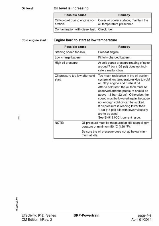
Oil level Oil level is increasing
Cold engine start Engine hard to start at low temperature
Possible cause Remedy
Oil too cold during engine op-eration.
Cover oil cooler surface, maintain the oil temperature prescribed.
Contamination with diesel fuel. Check fuel.
Possible cause Remedy
Starting speed too low. Preheat engine.
Low charge battery. Fit fully charged battery.
High oil pressure. At cold start a pressure reading of up to around 7 bar (102 psi) does not indi-cate a malfunction.
Oil pressure too low after cold start.
Too much resistance in the oil suction system at low temperatures due to cold oil. Stop engine and preheat oil.After a cold start the oil tank must be observed and the pressure should be above 1.5 bar (22 psi). Otherwise, the speed must be lowered again, because not enough cold oil can be sucked.If oil pressure is reading lower than 1 bar (15 psi) oils with lower viscosity are to be used. See SI-912 i-001, current issue.
NOTE: Oil pressure must be measured at idle at an oil tem-perature of minimum 50 °C (120 °F).
Be sure the oil pressure does not go below mini-mum at idle.
Effectivity: 912 i Series BRP-Powertrain page 4-9OM Edition 1/Rev. 2 April 01/2014

d058
73.fm
NOTES
Effectivity: 912 i Series BRP-Powertrain page 4-10OM Edition 1/Rev. 0 January 01/2012
d056
97.fm
5) Performance data
Introduction The performance tables and performance graphs on the next few pages are intended to show you what kind of performance to ex-pect from your engine in terms of power output. The indicated power can be achieved by following the procedures laid out in the Operators Manual and ensuring that the engine is well-main-tained.
Table of content This chapter of the Operators Manual contains performance table and performance graphs.
Subject Page
Performance data for standard conditions (ISA) Page 5-2
Fuel consumption 912 iSc/iS Page 5-3
Performance data for variable pitch propeller Page 5-4
Performance graph for non-standard conditions Page 5-5
Effectivity: 912 i Series BRP-Powertrain page 5-1OM Edition 1/Rev. 0 January 01/2012
d056
97.fm
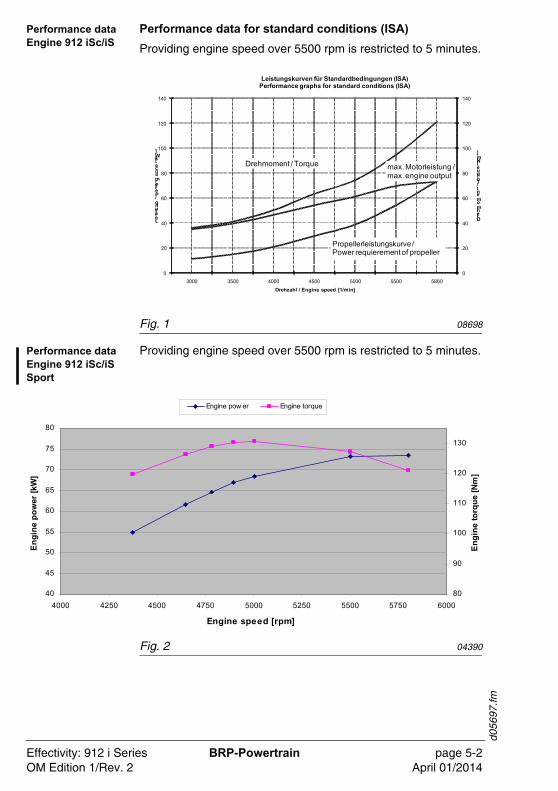
Performance data Engine 912 iSc/iS
Performance data for standard conditions (ISA)
Providing engine speed over 5500 rpm is restricted to 5 minutes.
Fig. 1 08698
Performance data Engine 912 iSc/iS Sport
Providing engine speed over 5500 rpm is restricted to 5 minutes.
Fig. 2 04390
0
20
40
60
80
100
120
140
0
20
40
60
80
100
120
140
3000 3500 4000 4500 5000 5500 5800
Drehmoment / Torque [Nm]
Leistung / Performance [kW]
Drehzahl / Engine speed [1/min]
Leistungskurven für Standardbedingungen (ISA)Performance graphs for standard conditions (ISA)
Propellerleistungskurve / Power requierement of propeller
Drehmoment / Torque max. Motorleistung / max. engine output
40
45
50
55
60
65
70
75
80
4000 4250 4500 4750 5000 5250 5500 5750 6000
Engine speed [rpm]
Engi
ne p
ower
[kW
]
80
90
100
110
120
130
Engi
ne to
rque
[Nm
]
Engine pow er Engine torque
Effectivity: 912 i Series BRP-Powertrain page 5-2OM Edition 1/Rev. 2 April 01/2014
d056
97.fm
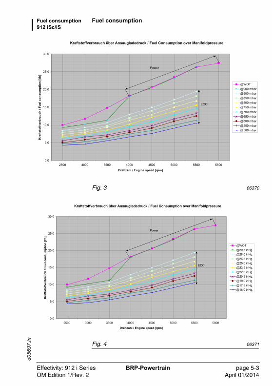
Fuel consumption 912 iSc/iS
Fuel consumption
Fig. 3 06370
Fig. 4 06371
Kraftstoffverbrauch über Ansaugladedruck / Fuel Consumption over Manifoldpressure
0,0
5,0
10,0
15,0
20,0
25,0
30,0
2500 3000 3500 4000 4500 5000 5500 5800
Drehzahl / Engine speed [rpm]
Kra
ftsto
ffver
brau
ch /
Fuel
con
sum
ptio
n [l/
h]
@WOT@950 mbar@900 mbar@850 mbar@800 mbar@750 mbar@700 mbar@650 mbar@600 mbar@550 mbar@500 mbar
Power
ECO
Kraftstoffverbrauch über Ansaugladedruck / Fuel Consumption over Manifoldpressure
0,0
5,0
10,0
15,0
20,0
25,0
30,0
2500 3000 3500 4000 4500 5000 5500 5800
Drehzahl / Engine speed [rpm]
Kra
ftsto
ffver
brau
ch /
Fuel
con
sum
ptio
n [l/
h]
@WOT@29,5 inHg.@28,0 inHg.@26,5 inHg.@25,0 inHg.@23,5 inHg.@22,0 inHg.@20,5 inHg.@19,0 inHg.@17,5 inHg.@16,0 inHg.
Power
ECO
Effectivity: 912 i Series BRP-Powertrain page 5-3OM Edition 1/Rev. 2 April 01/2014
d056
97.fm
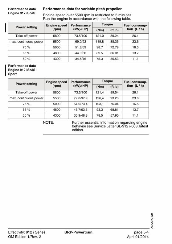
Performance data Engine 912 iSc/iS
Performance data for variable pitch propeller
Engine speed over 5500 rpm is restricted to 5 minutes. Run the engine in accordance with the following table.
Performance data Engine 912 iSc/iS Sport
NOTE: Further essential information regarding engine behavior see Service Letter SL-912 i-003, latest edition.
Power settingEngine speed
(rpm)Performance
(kW)/(HP)
Torque Fuel consump-tion (L / h) (Nm) (ft.lb)
Take-off power 5800 73.5/100 121.0 89.24 26.1
max. continuous power 5500 69.0/92 119.8 88.36 23.6
75 % 5000 51.8/69 98.7 72.79 16.5
65 % 4800 44.9/60 89.5 66.01 13.7
50 % 4300 34.5/46 75.3 55.53 11.1
Power settingEngine speed
(rpm)Performance
(kW)/(HP)
Torque Fuel consump-tion (L / h) (Nm) (ft.lb)
Take-off power 5800 73.5/100 121,4 89.54 26.1
max. continuous power 5500 72.0/97.9 126,4 93.23 23.6
75 % 5000 54.0/73.4 103,1 76.04 16.5
65 % 4800 46.7/63.5 93,3 68.81 13.7
50 % 4300 35.9/48.8 78,5 57.90 11.1
Effectivity: 912 i Series BRP-Powertrain page 5-4OM Edition 1/Rev. 2 April 01/2014
d056
97.fm
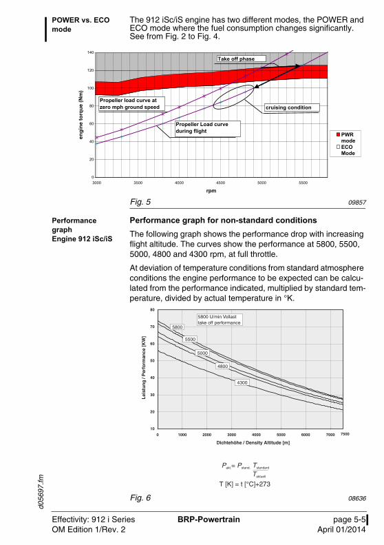
POWER vs. ECO mode
The 912 iSc/iS engine has two different modes, the POWER and ECO mode where the fuel consumption changes significantly. See from Fig. 2 to Fig. 4.
Fig. 5 09857
Performance graph Engine 912 iSc/iS
Performance graph for non-standard conditions
The following graph shows the performance drop with increasing flight altitude. The curves show the performance at 5800, 5500, 5000, 4800 and 4300 rpm, at full throttle.
At deviation of temperature conditions from standard atmosphere conditions the engine performance to be expected can be calcu-lated from the performance indicated, multiplied by standard tem-perature, divided by actual temperature in °K.
Fig. 6 08636
0
20
40
60
80
100
120
140
3000 3300 3800 4000 4300 4500 4800 5000 5300 5500 5800
rpm
engi
ne to
rque
(Nm
)
PWRmodeECOMode
0
20
40
60
80
100
120
140
3000 3500 4000 4500 5000 5500
cruising condition
Propeller Load curve during flight
Propeller load curve at zero mph ground speed
Take off phase
Effectivity: 912 i Series BRP-Powertrain page 5-5OM Edition 1/Rev. 2 April 01/2014

d056
97.fm
NOTES
Effectivity: 912 i Series BRP-Powertrain page 5-6OM Edition 1/Rev. 2 April 01/2014
d052
78.fm
6) Weights
Introduction The stated weights are dry weights (without operating fluids) and are guide values only.Further weight information relating to the equipment can be found in the current Installation Manual.
Table of content This chapter of the Operators Manual contains an extensive list of approved equipment for this engine.
Subject Page
Weights - Engine Page 6-2
Effectivity: 912 i Series BRP-Powertrain page 6-1OM Edition 1/Rev. 0 January 01/2012
d052
78.fm
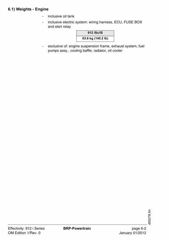
6.1) Weights - Engine
- inclusive oil tank
- inclusive electric system: wiring harness, ECU, FUSE BOX and start relay
- exclusive of: engine suspension frame, exhaust system, fuel pumps assy., cooling baffle, radiator, oil cooler
912 iSc/iS
63.6 kg (140.2 lb)
Effectivity: 912 i Series BRP-Powertrain page 6-2OM Edition 1/Rev. 0 January 01/2012
d058
71.fm
7) Description of systems
Introduction This chapter of the Operator Manual contains the description of cooling system, fuel system, lubrication system, electric system and the propeller gearbox.
Table of content As already mentioned in the preface, the system descriptions only apply to the engine, not to a specific application in a particular air-craft. The aircraft manufacturers Operators Manual is therefore definitive in terms of the operation of the engine, as it contains all the aircraft specific instructions.
Subject Page
Cooling system of engine CoolingCoolantExpansions tankCoolant temperature measuring
Page 7-2Page 7-2Page 7-2Page 7-2Page 7-2
Fuel systemFuelFuel pump switchesFuel pressure regulatorReturn line
Page 7-4Page 7-4Page 7-4Page 7-4Page 7-4
Lubrication systemLubricationCrankcaseOil pumpOil venting systemOil temperature sensorOil pressure sensor
Page 7-6Page 7-6Page 7-6Page 7-6Page 7-6Page 7-6Page 7-6
Electric systemEMS overviewEMS power supplyLANE select switch A/BEMS main switchIgnition systemFuel injectionECUMain functions of the ECU
Page 7-8Page 7-8Page 7-8Page 7-9Page 7-9Page 7-10Page 7-10Page 7-11Page 7-11
Propeller gearboxReduction ratioTorsional shock absorberGovernor
Page 7-12Page 7-12Page 7-12Page 7-12
Effectivity: 912 i Series BRP-Powertrain page 7-1OM Edition 1/Rev. 0 January 01/2012
d058
71.fm
7.1) Cooling system of the engine
General note See Fig. 1.
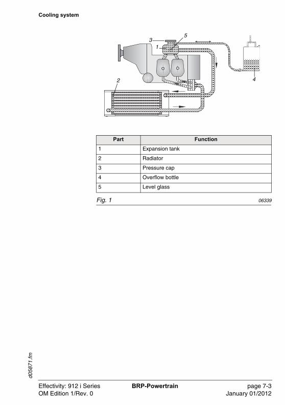
Cooling The cooling system of the engine is designed for liquid cooling of the cylinder heads and ram-air cooling of the cylinders. The coo-ling system of the cylinder heads is a closed circuit with an expan-sion tank.
Coolant The coolant flow is forced by a water pump, driven from the cams-haft, from the radiator to the cylinder heads. From the top of the cylinder heads the coolant passes on to the expansion tank (1). Since the standard location of the radiator (2) is below engine le-vel, the expansion tank located on top of the engine allows for coolant expansion.
Expansion tank The expansion tank is closed by a pressure cap (3) (with excess pressure valve and return valve). At temperature rise of the coolant the excess pressure valve opens and the coolant will flow via a hose at atmospheric pressure to the transparent overflow bottle (4). When cooling down, the coolant will be sucked back into the cooling circuit.
Coolant tempera-ture measuring
NOTE: The temperatur sensor at delivery is located in cylinder head 4.
Effectivity: 912 i Series BRP-Powertrain page 7-2OM Edition 1/Rev. 0 January 01/2012
d058
71.fm
Cooling system
Fig. 1 06339
13
42
5
Part Function
1 Expansion tank
2 Radiator
3 Pressure cap
4 Overflow bottle
5 Level glass
Effectivity: 912 i Series BRP-Powertrain page 7-3OM Edition 1/Rev. 0 January 01/2012
d058
71.fm
7.2) Fuel system
General note See Fig. 2.
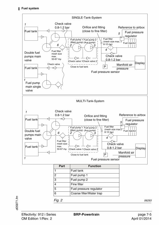
Fuel The fuel flows from the tank (1) via a fine filter (4) to the electric fuel pumps (2,3) from where it is then pumped to the fuel rail, the fuel injectors and to the fuel pressure regulator (5).
Fuel pump switch-es
The fuel pumps are activated directly through the switch OFF/ON. During take off both switches (main and aux.) must be ON.
Fuel pressure reg-ulator
A fuel pressure regulator ensures that the pressure differential be-tween the fuel injectors and the intake manifold remains constant. This enables the fuel injection system to inject the same quantity of fuel at any point given the same injection period.
Return line Through the return line surplus fuel flows back to the fuel tank and suction side of fuel system.
NOTE: The return line must be always returned into the tank, from which fuel is sucked in to the oil pump.
Effectivity: 912 i Series BRP-Powertrain page 7-4OM Edition 1/Rev. 0 January 01/2012
d058
71.fm
Fuel system
Fig. 2 06293
Part Function
1 Fuel tank
2 Fuel pump 1
3 Fuel pump 2
4 Fine filter
5 Fuel pressure regulator
6 Coarse filter/Water trap
1
1
32
4
5
6
1
1
6 2 34
5Fuel tank
Fuel tank
Fuel tank
Fuel tank
Check valve 0.8-1.2 bar Orifice and fitting
(close to fine filter)
Double fuel pumps main valve
Reference to airbox
Fuel pressure regulator
Fuel pressure sensor
Manifold air pressure
Check valve 0.8-1.2 bar Display
P
Fuel filtermesh sizemax. 50-67 mµ
Fuel filter(mesh size max. 8-12 mµ)
Fuel pump 1(Main pump)
Fuel pump 2(Aux pump)
Close to fuel tank
Check valve 1Check valve 2
Fuel injector
MULTI-Tank-System
SINGLE-Tank-System
Check valve 0.8-1.2 bar Orifice and fitting
(close to fine filter)Reference to airbox
Fuel pressure regulator
Fuel injector
Fuel filter(mesh size max. 8-12 mµ)
Check valve 0.8-1.2 bar
Manifold air pressure
DisplayPClose to fuel tank
Check valve 1Check valve 2
Fuel pressure sensor
Double fuel pumps main valve
Fuel pumpmain single valve
Fuel pump 1(Main pump)
Fuel pump 2(Aux pump)
Fuel filtermesh sizemax. 50-67 mµ
Check valve
Effectivity: 912 i Series BRP-Powertrain page 7-5OM Edition 1/Rev. 2 April 01/2014
d058
71.fm
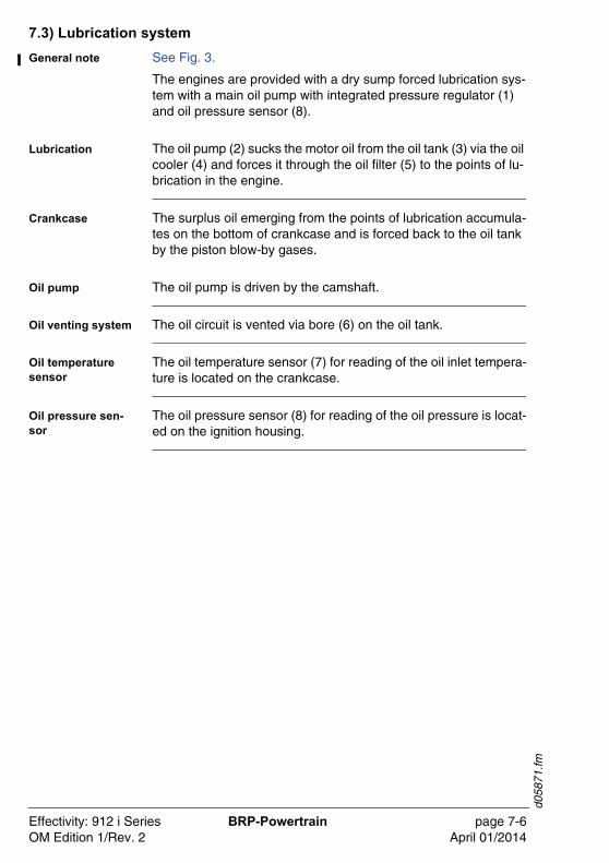
7.3) Lubrication system
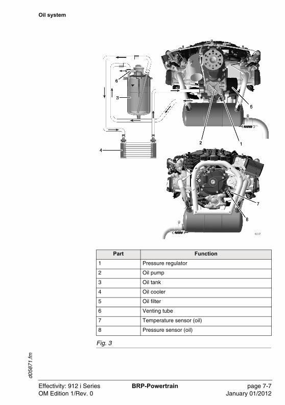
General note See Fig. 3.
The engines are provided with a dry sump forced lubrication sys-tem with a main oil pump with integrated pressure regulator (1) and oil pressure sensor (8).
Lubrication The oil pump (2) sucks the motor oil from the oil tank (3) via the oil cooler (4) and forces it through the oil filter (5) to the points of lu-brication in the engine.
Crankcase The surplus oil emerging from the points of lubrication accumula-tes on the bottom of crankcase and is forced back to the oil tank by the piston blow-by gases.
Oil pump The oil pump is driven by the camshaft.
Oil venting system The oil circuit is vented via bore (6) on the oil tank.
Oil temperature sensor
The oil temperature sensor (7) for reading of the oil inlet tempera-ture is located on the crankcase.
Oil pressure sen-sor
The oil pressure sensor (8) for reading of the oil pressure is locat-ed on the ignition housing.
Effectivity: 912 i Series BRP-Powertrain page 7-6OM Edition 1/Rev. 2 April 01/2014
d058
71.fm
Oil system
Fig. 3
Part Function
1 Pressure regulator
2 Oil pump
3 Oil tank
4 Oil cooler
5 Oil filter
6 Venting tube
7 Temperature sensor (oil)
8 Pressure sensor (oil)
Effectivity: 912 i Series BRP-Powertrain page 7-7OM Edition 1/Rev. 0 January 01/2012
d058
71.fm
7.4) Electric system
General note The ROTAX 912 iSc/iS is equipped with an electronic guided dual ignition unit with integrated generator. The ignition unit is easy to maintain and needs (except for start the engine) no external power supply.
EMS overview The EMS primarily comprises:
- High-voltage ignition components (connectors, spark plugs, ignition cables, double ignition coils)
- ECU
- ECU (actuators) - OUTPUT
- 4 doublesignition coils
- Lamps
- Fuel injection 2 per cylinder
- CAN data for an indicating instrument
- ECU (signals) - INPUT
- Sensors
- EMS power supply
- Regulator rectifier
- Generator
- FUSE BOX ( all power supply components, including the fus-es, etc., can be found in the power supply unit)
- Switches
- Cables/wiring
EMS power supply The EMS power supply primarily comprises 2 alternators with per-manent magnets. It also comprises an external rectifier, voltage stabilizer and overvoltage protection, which are integrated in the FUSE BOX. The two 3-phase A/C current generators (alternators) are physically separated in the engine integrated power supply units. One is used for the ECU and the other one is available for the aircraft. They are driven by the crankshaft and require no ex-ternal supply once the engine has reached its idle speed.
NOTE: Until the idle speed is reached, the EMS re-quires an external 12 V supply from the on-board system of the aircraft.
Effectivity: 912 i Series BRP-Powertrain page 7-8OM Edition 1/Rev. 0 January 01/2012
d058
71.fm
LANE select switches A/B
The two independent LANE select switches A and B connect the ECU for the relevant LANE to the EMS power supply.
The start power switch makes a connection only during the start-up procedure between the ECU, ignition system and the EMS lamps with the external onboard battery.
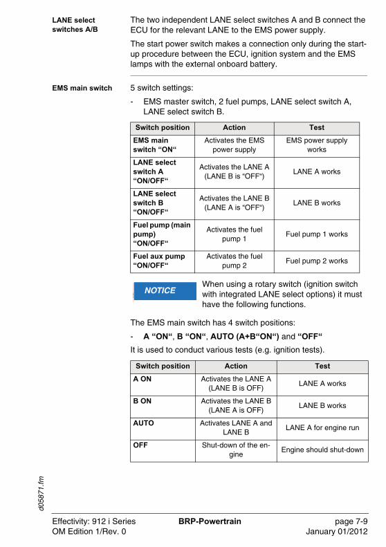
EMS main switch 5 switch settings:
- EMS master switch, 2 fuel pumps, LANE select switch A, LANE select switch B.
The EMS main switch has 4 switch positions:
- A “ON“, B “ON“, AUTO (A+B“ON“) and “OFF“
It is used to conduct various tests (e.g. ignition tests).
Switch position Action Test
EMS main switch “ON“
Activates the EMS power supply
EMS power supply works
LANE select switch A “ON/OFF“
Activates the LANE A (LANE B is “OFF“)
LANE A works
LANE select switch B “ON/OFF“
Activates the LANE B (LANE A is “OFF“)
LANE B works
Fuel pump (main pump) “ON/OFF“
Activates the fuel pump 1
Fuel pump 1 works
Fuel aux pump “ON/OFF“
Activates the fuel pump 2
Fuel pump 2 works
�WARNUNGNOTICEWhen using a rotary switch (ignition switch with integrated LANE select options) it must have the following functions.
Switch position Action Test
A ON Activates the LANE A (LANE B is OFF)
LANE A works
B ON Activates the LANE B (LANE A is OFF)
LANE B works
AUTO Activates LANE A and LANE B
LANE A for engine run
OFF Shut-down of the en-gine
Engine should shut-down
Effectivity: 912 i Series BRP-Powertrain page 7-9OM Edition 1/Rev. 0 January 01/2012
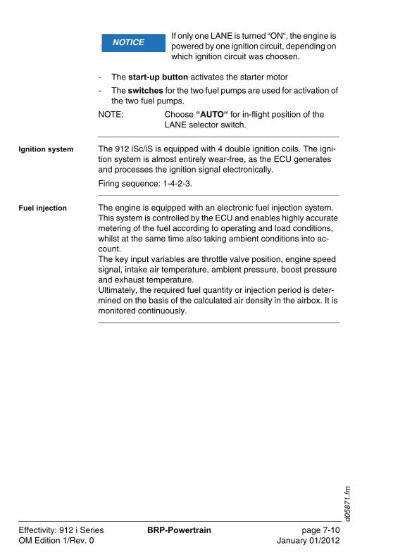
d058
71.fm
- The start-up button activates the starter motor
- The switches for the two fuel pumps are used for activation of the two fuel pumps.
NOTE: Choose “AUTO“ for in-flight position of the LANE selector switch.
Ignition system The 912 iSc/iS is equipped with 4 double ignition coils. The igni-tion system is almost entirely wear-free, as the ECU generates and processes the ignition signal electronically.
Firing sequence: 1-4-2-3.
Fuel injection The engine is equipped with an electronic fuel injection system. This system is controlled by the ECU and enables highly accurate metering of the fuel according to operating and load conditions, whilst at the same time also taking ambient conditions into ac-count. The key input variables are throttle valve position, engine speed signal, intake air temperature, ambient pressure, boost pressure and exhaust temperature.Ultimately, the required fuel quantity or injection period is deter-mined on the basis of the calculated air density in the airbox. It is monitored continuously.
�WARNUNGNOTICEIf only one LANE is turned “ON“, the engine is powered by one ignition circuit, depending on which ignition circuit was choosen.
Effectivity: 912 i Series BRP-Powertrain page 7-10OM Edition 1/Rev. 0 January 01/2012
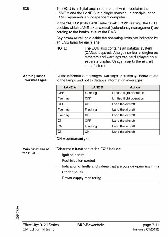
d058
71.fm
ECU The ECU is a digital engine control unit which contains the LANE A and the LANE B in a single housing. In principle, each LANE represents an independent computer.
In the “AUTO“ (both LANE select switch “ON“) setting, the ECU decides which LANE takes control (redundancy management) ac-cording to the health level of the EMS.
Any errors or values outside the operating limits are indicated by an EMS lamp for each lane.
NOTE: The ECU also contains an databus system (CANaerospace). A large number of engine pa-rameters and warnings can be displayed on a separate display. Usage is up to the aircraft manufacturer.
Warning lampsError messages
All the information messages, warnings and displays below relate to the lamps and not to databus information messages.
ON = permanently on
Main functions of the ECU
Other main functions of the ECU include:
- Ignition control
- Fuel injection control
- Indication of faults and values that are outside operating limits
- Storing faults
- Power supply monitoring
LANE A LANE B Action
OFF Flashing Limited flight operation
Flashing OFF Limited flight operation
OFF ON Land the aircraft
Flashing Flashing Land the aircraft
Flashing ON Land the aircraft
ON OFF Land the aircraft
ON Flashing Land the aircraft
ON ON Land the aircraft
Effectivity: 912 i Series BRP-Powertrain page 7-11OM Edition 1/Rev. 0 January 01/2012
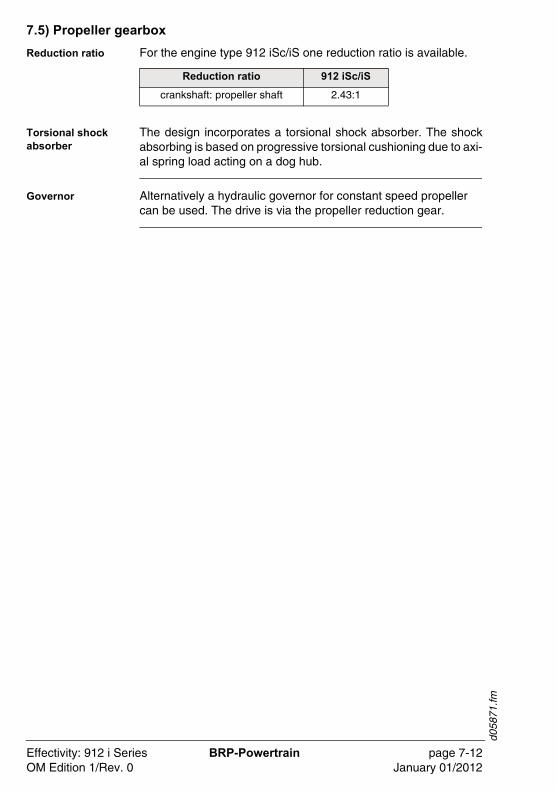
d058
71.fm
7.5) Propeller gearbox
Reduction ratio For the engine type 912 iSc/iS one reduction ratio is available.
Torsional shock absorber
The design incorporates a torsional shock absorber. The shockabsorbing is based on progressive torsional cushioning due to axi-al spring load acting on a dog hub.
Governor Alternatively a hydraulic governor for constant speed propeller can be used. The drive is via the propeller reduction gear.
Reduction ratio 912 iSc/iS
crankshaft: propeller shaft 2.43:1
Effectivity: 912 i Series BRP-Powertrain page 7-12OM Edition 1/Rev. 0 January 01/2012
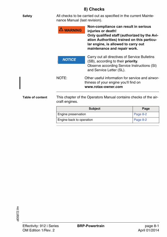
d058
72.fm
8) Checks
Safety All checks to be carried out as specified in the current Mainte-nance Manual (last revision).
NOTE: Other useful information for service and airwor-thiness of your engine you‘ll find on www.rotax-owner.com
Table of content This chapter of the Operators Manual contains checks of the air-craft engines.
�WARNU� WARNINGNon-compliance can result in serious injuries or death!Only qualified staff (authorized by the Avi-ation Authorities) trained on this particu-lar engine, is allowed to carry out maintenance and repair work.
�WARNUNGNOTICECarry out all directives of Service Bulletins (SB), according to their priority.Observe according Service Instructions (SI) and Service Letter (SL).
Subject Page
Engine preservation Page 8-2
Engine back to operation Page 8-2
Effectivity: 912 i Series BRP-Powertrain page 8-1OM Edition 1/Rev. 2 April 01/2014
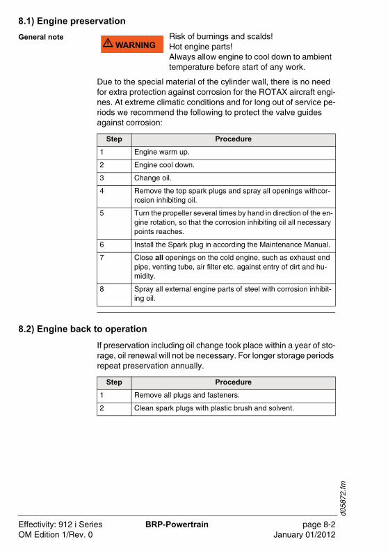
d058
72.fm
8.1) Engine preservation
General note
Due to the special material of the cylinder wall, there is no need for extra protection against corrosion for the ROTAX aircraft engi-nes. At extreme climatic conditions and for long out of service pe-riods we recommend the following to protect the valve guides against corrosion:
8.2) Engine back to operation
If preservation including oil change took place within a year of sto-rage, oil renewal will not be necessary. For longer storage periods repeat preservation annually.
�WARNU� WARNINGRisk of burnings and scalds!Hot engine parts!Always allow engine to cool down to ambient temperature before start of any work.
Step Procedure
1 Engine warm up.
2 Engine cool down.
3 Change oil.
4 Remove the top spark plugs and spray all openings withcor-rosion inhibiting oil.
5 Turn the propeller several times by hand in direction of the en-gine rotation, so that the corrosion inhibiting oil all necessary points reaches.
6 Install the Spark plug in according the Maintenance Manual.
7 Close all openings on the cold engine, such as exhaust end pipe, venting tube, air filter etc. against entry of dirt and hu-midity.
8 Spray all external engine parts of steel with corrosion inhibit-ing oil.
Step Procedure
1 Remove all plugs and fasteners.
2 Clean spark plugs with plastic brush and solvent.
Effectivity: 912 i Series BRP-Powertrain page 8-2OM Edition 1/Rev. 0 January 01/2012
d056
98.fm
9) Supplement
Introduction According to the regulation of EASA part 21 A.3 / FAR 21.3 the manufacturer shall evaluate field information and report to the au-thority. In case of any relevant occurrences that may involve mal-function of the engine, the form on the next page should be filled out and sent to the responsible authorized ROTAX® distributor.
NOTE: The form is also available from the official ROTAX® AIRCRAFT ENGINES Website in electronic version.
www.FLYROTAX.com
Table of content This chapter of the Operators Manual contains the form and the list of authorized distributors for ROTAX aircraft engines.
Subject Page
Form Page 9-3
Authorized distributors Page 9-5
Effectivity: 912 i Series BRP-Powertrain page 9-1OM Edition 1/Rev. 0 January 01/2012

d056
98.fm
NOTES
Effectivity: 912 i Series BRP-Powertrain page 9-2OM Edition 1/Rev. 0 January 01/2012
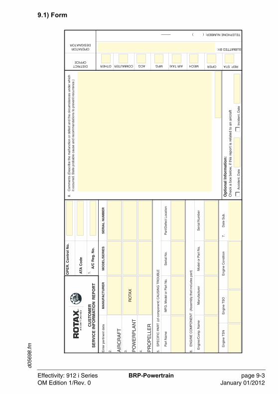
d056
98.fm
9.1) Form
Effectivity: 912 i Series BRP-Powertrain page 9-3OM Edition 1/Rev. 0 January 01/2012

d056
98.fm
NOTES
Effectivity: 912 i Series BRP-Powertrain page 9-4OM Edition 1/Rev. 0 January 01/2012
d056
98.fm
9.2) Authorized Distributor
General note See the official ROTAX® AIRCRAFT ENGINES Website www.FLYROTAX.com
List Overview about authorized distributor for ROTAX aircraft engines.
Subject Page
Europe Page 9-6
AmericaAustraliaAfrica
Page 9-7Page 9-7Page 9-7
Asia Page 9-8
Effectivity: 912 i Series BRP-Powertrain page 9-5OM Edition 1/Rev. 0 January 01/2012

d056
98.fm
1) E U R O P E
CZECHIA / SLOVAKIA:➤TEVESO S.R.O.
Skroupova 441CS-50002 HRADEC KRALOVETel.: +42 049 / 5217 127,Fax: +42 049 / 5217 226 E-mail: [email protected]: www.teveso.czContact persons: Ing. Jiri Samal
GREAT BRITAIN / IRELAND / ICELAND:
➤SKYDRIVE LTD.Burnside, Deppers BridgeSOUTHAM, WARWICKSHIRE CV47 2SUTel.: +44 (0) 1926 / 612 188, Fax: +44 (0) 1926 / 613 781E-mail: [email protected]: www.skydrive.co.ukContact person: Nigel Beale
SWEDEN / FINLAND / NORWAY / ESTONIA / LATVIA / LITHUANIA / DENMARK:
➤LYCON ENGINEERING ABHärkeberga, SE-74596 ENKÖPINGTel.: +46 (0) 171 / 414039, E-mail: [email protected]: www.aeronord.eu
SLOVENIA:➤PIPISTREL D.O.O. AJDOVSCINA
Goriska Cesta 50A5270 AJDOVSCINATel.: +386 (0) 5 / 3663 873, Fax: +386 (0) 5 / 3661 263E-mail:[email protected]:www.pipistrel.siContact person: Leon Brecelj
FRANCE / ALGERIA / BELGIUM / LU-XEMBURG / MAROCCO / MONACO / TUNESIA:
➤MOTEUR AERO DISTRIBUTION11 Blvd Albert 198000 MONACOTel.: +377 (0) 93 30 17 40, Fax: +377 (0) 93 30 17 60E-mail: [email protected]: www.moteuraerodistribution.comContact person: Philippe Thys
POLAND: ➤FASTON LTD.
ul. Zwirki i Wigury 47PL-21-040 SWIDNIKTel.: +48 (0) 81/ 751-2882; Fax: +48 (0) 81 / 751-5740E-mail: [email protected] person: Mariusz Oltarzewski
GERMANY / AUSTRIA / BULGARIA / HUNGARY / LIECHTENSTEIN / ROMANIA / SWITZERLAND / THE NETHERLANDS:
➤FRANZ AIRCRAFT ENGINES VERTRIEB GMBHAm Weidengrund 1a, 83135 Schechen, GERMANYTel.: +49 (0) 8039 / 90350, Fax: +49 (0) 8039 / 9035-35E-mail: [email protected]: www.franz-aircraft.deContact person: Eduard Franz
ITALY / CROATIA / CYPRUS / GREECE / MALTA / PORTUGAL / SPAIN / TUR-KEY / FORMER YUGOSLAVIA (EXEPT SLOVENIA)
➤LUCIANO SORLINI S.P.A.Piazza Roma, 1Carzago di Calvagese Riviera (Brescia), ItalyTel.: +39 030 / 601 033, Fax: +39 030 / 601 463E-mail: [email protected]: www.sorlini.comContact person: Alberto Comincioli
Effectivity: 912 i Series BRP-Powertrain page 9-6OM Edition 1/Rev. 0 January 01/2012
d056
98.fm
2) A M E R I C ACANADA:➤ROTECH RESEARCH CANADA, LTD.6235 Okanagan Landing Rd.VERNON, B.C., V1H 1M5, CANADATel.: +1 250 / 260-6299, Fax: +1 250 / 260-6269E-mail: [email protected]: www.rotec.com
NORTH / MIDDLE / SOUTH AMERICA: ➤KODIAK RESEARCH LTD.
P.O. Box N 658Bay & Deveaux StreetNASSAU, BAHAMASTel.: +1 242 / 356 5377, Fax: +1 242 / 356 2409E-mail: [email protected]: www.kodiakbs.com
3) A U S T R A L I A / N E W Z E A L A N D / P A P U A N E W G U I N E A:
➤BERT FLOOD IMPORTS PTY. LTD.P.O. Box 61, 16-17 Chris Drive LILYDALE, VICTORIA 3140Tel.: +61 (0) 3 / 9735 5655, Fax: +61 (0) 3 / 9735 5699E-mail: [email protected]: www.bertfloodimports.com.auContact person: Mark Lester
4) A F R I C A EGYPT:
➤AL MOALLAP.O. Box 7787, ABU DHABITel.: +971 (0) 2/ 444 7378, Fax: +971 (0) 2/444 6896E-mail: [email protected] person: Hussain Al Moalla
LIBYA:➤LUCIANO SORLINI S.P.A.
Piazza Roma, 1Carzago di Calvagese Riviera (Brescia), ItalyTel.: +39 030 / 601 033, Fax: +39 030 / 601 463E-mail: [email protected]: www.sorlini.comContact person: Alberto Comincioli
ANGOLA / BOTSWANA / LESOTHO/ MADAGASCAR / MALAWI / MOZAM-BIQUE/ NAMIBIA / SOUTH AFRICA / SWAZILAND/ ZAMBIA / ZIMBABWE:
➤AVIATION ENGINES ANDACCESSORIES (PTY) LTDP.O. Box 15749, Lambton 1414, SOUTH AFRICATel.: +27 (0) 11 / 824 3368, Fax: +27 (0) 11 / 824 3339E-mail: [email protected]: www.aviation-engines.co.zaContact person: Niren Chotoki
GHANA / BENIN / BURKINA FASO / CAMEROON / CENTRAL AFRICAN REPUBLIC / CONGO / GABON / GUINEA / IVORY COAST / MALI /MAURITANIA / NIGER/ NIGERIA / SENEGAL / TOGO:
➤WAASPS LTDPMB KA49, Kotoka International Airport, Accra, GHANATel.: +233 (0) 28 5075254, Fax: +233 (0) 217 717 92E-mail:[email protected]:www.waasps.comContact person: Jonathan Porter
Effectivity: 912 i Series BRP-Powertrain page 9-7OM Edition 1/Rev. 0 January 01/2012

d056
98.fm
5) A S I ACHINA / HONG KONG / MACAO:
➤PEIPORT INDUSTRIES LTD.Rm. 1302, Westlands Centre20 Westlands Road, Quarry BayHONG KONGTel.: +852 (0) 2885 / 9525, Fax: +852 (0) 2886 / 3241E-mail: [email protected]: www.peiport.comContact person: Larry Yeung
ISRAEL: ➤LUCIANO SORLINI S.P.A.
Piazza Roma, 1Carzago di Calvagese Riviera (Brescia), ItalyTel.: +39 030 / 601 033, Fax: +39 030 / 601 463E-mail: [email protected]: www.sorlini.comContact person: Alberto Comincioli
CIS:➤AVIAGAMMA JSCO.
P.O. Box 51, 125 057 MOSCOWTel.: +7 499 / 158 31 23, Fax: +7 499 / 158 62 22E-mail: [email protected]: www.aviagamma.ruContact person: Vladimir Andriytschuk General Director
JAPAN : ➤JUA, LTD.
1793 Fukazawa, Gotemba CitySHIZUOKA PREF 412Tel.: +81 (0) 550 / 83 8860, Fax: +81 (0) 550 / 83 8224E-mail: [email protected] person:Yoshihiko Tajika President
KOREA:➤KOREA BUSINESS AIR SERVICE CO. LTD.
672-4 KBAS Bldg. Deungchon-dong,Kangseo-ku, Seoul, South Korea Tel.: +82 (0) 2 / 3664 - 6644Fax: +82 (0) 2 / 2658 - 6562E-mail: [email protected]: www.kbas.comContact person:Su Dong Lim
INDIA:➤VARMAN AVIATION PVT. LTD.
Aviation Complex, 16-17EPIP, Whitefield BANGALORE - 560066Tel.: +91 (0) 80 / 28412536, 28412655, 28412656Fax: +91 (0) 80 / 28413559E-mail: [email protected]: www.varman.comContact person: M. M. Varman
INDONESIA / MALAYSIA / PHILIP-PINES / SINGAPORE / THAILAND / TAIWAN:
➤BERT FLOOD IMPORTS PTY. LTD.P.O. Box 61, 16-17 Chris Drive LILYDALE,VICTORIA 3140Tel.: +61 (0) 3 / 9735 5655, Fax: +61 (0) 3 / 9735 5699E-mail:[email protected]: www.bertfloodimports.com.auContact person: Mark Lester
IRAN: ➤ASEMAN PISHRANEH CO.
Register Code: 14943213 Km of Babaee Exp. Way, next to Telo Road, Sepehr Aero Club, Tehran, IRANTel.: +98 (0) 21 77000201,Fax: +98 (0) 21 77000030E-mail: [email protected] person: Ali Habibi Najafi
UNITED ARAB. EMIRATES:➤AL MOALLA
P.O. Box 7787ABU DHABITel.: +971 (0) 2 / 444 7378, Fax: +971 (0) 2 / 444 6896E-mail: [email protected] person: Hussain Al Moalla
PAKISTAN: ➤LUCIANO SORLINI S.P.A.
Piazza Roma, 1Carzago di Calvagese Riviera (Brescia), ItalyTel.: +39 030 / 601 033, Fax: +39 030 / 601 463E-mail: [email protected]: www.sorlini.comContact person: Alberto Comincioli
Effectivity: 912 i Series BRP-Powertrain page 9-8OM Edition 1/Rev. 2 April 01/2014

AIRCRAFT ENGINES
Related Documents


![Contract for Services - Digital Health...Contract for Services Reference No: [Add ref number] Customer Customer Name Australian Digital Health Agency Customer ABN 84 425 496 912 Address](https://static.cupdf.com/doc/110x72/5ed2c61807bf3476a34764be/contract-for-services-digital-health-contract-for-services-reference-no-add.jpg)