�� � Govement of India � � Bhabha Atomic Research Centre � m� 4UI Health Safety & Environment Group QfcHDI �� iH Environmental Monitoring and Assessment Division �. � Trombay, Mumbai 400 085 Ref. No.: EMAD/CRF/SM/2022/9/ Date: Feb 22, 2022 Sealed tenders are invited on behalf of the President of India by Head, Environmental Monitoring and Assessment Division, Bhabha Atomic Research Centre, Trombay, Mumbai- 400 085 om reputed contractors r the llowing work having adequate experience and capabilities to execute such a magnitude of similar works and who have similar experience with different units of Department ofAtomic Ener (DAE), Nuclear Power Corporation oflndia Pvt Ltd, Public Undertakings etc. Scope ofthe work: Design, fabrication, supply, installation, testing and commissioning of Class 10, 000 Clean Room with Class 100 Clean Bench and Fume Hood facili for ED at ºRC Hospital, Anushaktinagar, Mumbai-94" which includes Installation of HVAC system corresponding to the class of clean room (Class 10,000) involving AHU, HEPA filters, condensing units, Ducting, panels etc, lnstallation ofFume Hood and Clean bench ofClass 100, Electrical works of providing power-point, data-point, telephone line and electrical panels etc., Civil work involving modification of doors, windows, flooring, fitting of taps & sink etc. Estimated cost � 48,00,000.00 Earnest Money Deposit (EMO � 96,000.00 @ 2% of estimated cost) Period of Letter of intent 24-Feb-2022 to 10-March-2022 request (by email) Period of completion 06 months to be counted om the date of placement of work-order. Site visit and Pre bid Pre bid queries shall be sent by email to [email protected].in with a copy clarification to [email protected].in on or before 14-March-2022 11 :59:00 PM. All queries shall be clarified to all firms in Pre-Bid meeting on 16-March- 2022 14.30 PM at the site. Last date r Submission of 30-March-2022 tender in Hardcopy through Indian speed Post/registered Post (in EMAD office (BARC Hospital Mumbai) bere 16:00 Hrs. Opening Date 31-March-2022 Eligibility criteria (Documents required) r offer submission: I) Valid GST registration. 2) Permanent Account Number (PAN). 3) Experience ofhaving satisctorily executed the work of atleast 2 nos. of "Class 10,000 Clean Room with AHU, HEPA filters, condensing units, Ducting, panels etc" in last 5 years. 4) Bidders should have average turnover of at least 1 Cr. r the last three financial years. 5) Bidders should prerably have their office/contact point in Mumbai metropolitan region. 1. The interested bidders shall submit their Letter of Intent (by EmaH) along with proof of all eligibility documents (indicated above) within due dates iling which their bids shall be rejected. 2. The sealed quotations to be send to 'Dr. Suchismita Mishra, R.No. B-61, BARC Hospital, EMAD, Anushaktinagar - 400094' on or bere 30.03.2022 16:00 hrs by writing on top of the envelope l/2

Welcome message from author
This document is posted to help you gain knowledge. Please leave a comment to let me know what you think about it! Share it to your friends and learn new things together.
Transcript

��
'J..fRa � Government of India 'l-lT'l-lT � '3f¥Tw;r � Bhabha Atomic Research Centre
� m� 'Q'ci 4llfu'{UI Gf7'f Health Safety & Environment Group QllfcHDI �� elm Sic-llicfH Jf:PfTTf Environmental Monitoring and Assessment Division
�. � Trombay, Mumbai 400 085 Ref. No.: EMAD/CRF/SM/2022/9/ Date: Feb 22, 2022
Sealed tenders are invited on behalf of the President of India by Head, Environmental Monitoring and Assessment Division, Bhabha Atomic Research Centre, Trombay, Mumbai- 400 085 from reputed contractors for the following work having adequate experience and capabilities to execute such a magnitude of similar works and who have similar experience with different units of Department of Atomic Energy (DAE), Nuclear Power Corporation oflndia Pvt Ltd, Public Undertakings etc.
Scope of the work: Design, fabrication, supply, installation, testing and commissioning of Class 10, 000 CleanRoom with Class 100 Clean Bench and Fume Hood facility for EMAD at BARC Hospital, Anushaktinagar, Mumbai-94" which includes Installation of HVAC system corresponding to the class of clean room (Class 10,000) involving AHU, HEPA filters, condensing units, Ducting, panels etc, lnstallation ofFume Hood and Clean bench of Class 100, Electrical works of providing power-point, data-point, telephone line and electrical panels etc., Civil work involving modification of doors, windows, flooring, fitting of taps & sink etc.
Estimated cost � 48,00,000.00
Earnest Money Deposit (EMO � 96,000.00
@ 2% of estimated cost) Period of Letter of intent 24-Feb-2022 to 10-March-2022request (by email) Period of completion 06 months to be counted from the date of placement of work-order. Site visit and Pre bid Pre bid queries shall be sent by email to [email protected] with a copy clarification to [email protected] on or before 14-March-2022 11 :59:00 PM. All
queries shall be clarified to all firms in Pre-Bid meeting on 16-March-2022 14.30 PM at the site.
Last date for Submission of 30-March-2022tender in Hardcopy through Indian speed Post/registered Post (in EMAD office (BARC Hospital Mumbai) before 16:00 Hrs. Opening Date 31-March-2022
Eligibility criteria (Documents required) for offer submission: I) Valid GST registration. 2) Permanent Account Number (PAN).
3) Experience of having satisfactorily executed the work of atleast 2nos. of "Class 10,000 Clean Room with AHU, HEPA filters,condensing units, Ducting, panels etc" in last 5 years.
4) Bidders should have average turnover of at least 1 Cr. for the lastthree financial years.
5) Bidders should preferably have their office/contact point inMumbai metropolitan region.
1. The interested bidders shall submit their Letter of Intent (by EmaH) along with proof of all eligibilitydocuments (indicated above) within due dates failing which their bids shall be rejected.
2. The sealed quotations to be send to 'Dr. Suchismita Mishra, R.No. B-61, BARC Hospital, EMAD,Anushaktinagar - 400094' on or before 30.03.2022 16:00 hrs by writing on top of the envelope
qNmfl/2


पृष्ठ संख्या 1 / 1
सामान्य दिशादििेश (General guidelines)
Name of Work: Supply, installation, testing and commissioning of Class 10,000 Clean Room for EMAD at
BARC Hospital, Anushaktinagar, Mumbai.
a) Contractor/Bidder are requested to see the site before quote and read the technical specification/scope of
work carefully. In case of any query, it should be discussed in Pre-bid meeting.
b) All types of labour /services charges, hiring of equipments, taxes etc. are included in the cost of tender. No
extra payment shall be made unless otherwise clearly stated.
c) In case of any complaint, complaint shall be recorded in complaint book & sign shall be obtained from
user/department after attending the complaint.
d) Contractor should take care that no damage to department is caused. If any damage occurs, contractor is
liable to repair the damage and bring it to original shape & size at his own cost.
e) Contractor shall adhere to the laid down rules & regulations by department for the safety and security of
their labours at their own cost & risk.
f) Whenever an equivalent make/model is offered, the same will be scrutinized by department & approved.
Alternate make/model shall be accepted only after approval of department.
g) Water & electricity will be provided free of cost at one point at site. Contractor shall have to make
necessary arrangements for extension of the same up to required location.
h) A joint measurement (by Contractor & Engineer) shall be made for items supplied & installed at site for
subsequent payment/processing of RA (Running Accounts) bill.
i) The following E-i-C (Engineer in charge) will be responsible for the execution of item-wise work.
Mechanical Items, Item no. 1 to 15 : EiC, Mechanical, TSD, BARC Hospital
Civil Items, Item no. 16 to 24: EiC, Civil, TSD, BARC Hospital
Electrical Items, Item no. 25 to 43: EiC, Electrical, TSD, BARC Hospital
Laboratory Items, Item no. 44 to 49: OiC, ETAG, EMAD, BARC Hospital
j) Liability during warranty Period 1. After successful completion of the work & commissioning of the system, the firm shall communicate
the preventive maintenance activity & schedule with contact person for defect liability period.
2. The Firm shall provide one service per quarter for preventive maintenance of the system.
3. Emergency breakdown calls should be attended within 04 hours & normal complaints should be
attended within 24 hours. Failing this ₹2000 per day will be deducted from security deposit of the firm
for each instance.
4. If the complaint is not attended within above mentioned time, department will be free
to get the work done from any agency/source & deduct the amount incurred from security deposit.
k) Bidders have to write/quote their item-wise rates & total rate inclusive of supply, installation, testing,
commissioning, transportation, other charges etc only in our specified format of Schedule of quantity in
Annexure I. Any other format will not be accepted. Also, Bidders shall provide full specifications offered
by them or noted by them as in Annexure II (Mechanical Items), III (Civil Items), IV (Electrical
Items) & V (Laboratory Items). Simply writing the term Noted/ Agreed is discouraged. On such
instances bidders would be asked to submit the document again with full specification offered by them,
which may cause delay in opening of tender or even rejection of technical offer as deemed fit by competent
authority.

Annexure-I
Design, fabrication, supply, installation, testing and
commissioning of the following systems conforming to technical
specifications, drawings and specific requirements for the
equipments as mentioned under various clauses of technical
specification.
1.0 Air handling unit:
Double skin type Air handling unit suitable for clean room
application, interlocked with condensing units and complete
with fan, DX cooling coil, eliminator, filters, mixing chambers
etc. having thermal break profile of following capacities and as
per technical specification.
1.1 a) Capacity : 5.5 TR & 2400 CFM 1 No. No.
b) St. Pressure : 100 mm of WC
1.2 a) Capacity : 3 TR & 500 CFM 1 No. No.
b) St. Pressure : 50 mm of WC
2.0 Air cooled Outdoor unit:
Microprocessor based air cooled outdoor unit containing
compressor, condensor etc along with associated accessories as
per technical specification.
2.1 a) Capacity : 5.5 TR (approx) 1 No. No.
b) Type : Air cooled, Scroll Compressor
2.2 a) Capacity : 3 TR (approx) 1 No. No.
b) Type : Air cooled, Scroll Compressor
3.0 Clean Room Partition, Finishes & Flooring:
Clean room partition & finishes as per technical specifications.
3.1 Clean Room Panels: 30 Sq.M Sq.M
Clean room compatible double skin type panel of 50 mm
thickness by sandwiching insulation between 0.8 mm thk SS 304
sheet formed into modular panels with the provision of electrical
services & glass windows as per technical specification.
3.2 Clean Room Riser Panels: 30 Sq.M Sq.M
Clean room compatible double skin type panel of 100 mm
thickness by sandwiching insulation between 0.8 mm thk SS 304
sheet formed into modular panels with the provision of electrical
services, duct riser etc as per technical specification.
3.3 Ceiling Panels: 25 Sq.M Sq.M
Clean room compatible double skin type false ceiling by
sandwiching insulation between 0.8 mm thk SS 304 sheet
formed into 50 mm thick modular panels with a provision of
supporting from the ceiling as per technical specification.
3.4 Stainless Steel Coving 100 R.M. R.M.
stainless steel coving having approx. 65 mm face width for all
partition and ceiling corner joints of clean room as per technical
specification.
3.5 Clean Room Door
10 mm thick toughened clear glass clean room door with door
frame containing gasket, concealed door closer, tower bolt,
hinges etc. of following size and as per technical specification.
Double leaf door of size (apprx.): 1500(W)x2100(H) 1 No. Each
अनुसूची 'बी' (Schedule 'B')
मात्रा की अनुसूची (Schedule of Quantity)
Name of Work: Supply, installation, testing and commissioning of Class 10,000 Clean Room for EMAD at BARC Hospital,
Anushaktinagar, Mumbai.
S. No. Description of Items Qty. Unit RateTotal Amount
in Rs
MECHANICAL ITEMS
पृष्ठ संख्या 1 / 6

S. No. Description of Items Qty. Unit RateTotal Amount
in Rs
4.0 Clean Room Flooring: 25 Sq.M Sq.M
Self levelling Epoxy flooring, including preparation of the
surface, primer coat, screeding, levelling coat and finishing coat
with polyurethane coat of approved colour and shade
manufactured as per technical specification.
5.0 Return air diffuser: 1 No. Each
Return air diffuser of size 600 x 600 mm (approx) with in built
damper and as per technical specifications.
6.0 Refrigeration type Dehumidifier 1 No. Each
Refrigeration type Dehumidifier of 35 L (approx.) per day
moisture removal capacity along with PVC piping arrangement
for water drainage as per technical specification.
7.0 Air curtain: 1 No. Each
Air curtain of following duty duly powder coated as per
technical specifications.
Length : 1600 mm (approx.)
Velocity : 12 m/s (min.)
Height : 300 mm (approx.)
8.0 HEPA Filter: 7 Nos. Each
Separatorless Minipleat HEPA filters as per following details
and as per technical specification.
a) Size: 610 x 610 x 68 mm (approx.)
b) Type : Minipleat Separatorless
c) Flow : 500 CFM
d) Pressure Drop : Less than 18 mm of W.C at rated flow.
e) Efficiency : 99.97% down to 0.3 micron.
9.0 Terminal HEPA filter Box: 7 Nos. Each
Terminal HEPA filter box fabricated out of 18 gauge GI sheet
duly powder coated with in-built volume control damper, SS
perforated sheet, bevel gear arrangement, DOP injection port,
pressure measurement port etc. and suitable for mounting HEPA
filters mentioned under item no. 8.0 (HEPA Filter) and as per
technical specification.
10.0 Magnehellic Gauge:
Magnehellic gauges with suitable connecting PVC tubing of
following ranges and as per technical specification.
10.1 0-10 mm of WC 2 Nos. Each
10.2 0-50 mm of WC 2 Nos. Each
11.0 GI Duct:
Supply and return air ducting fabricated out of GI sheets having
following thickness (gauges) and as per technical specification.
22 G (0.8 mm thick) 40 Sq.M Sq. M
12.0 Damper: 2 Sq.M Sq. M
Manually operated heavy duty opposed blade type multilouvered
damper with outer body frame and blades fabricated out of
extruded Al section and aerofoil section respectively as per
technical specification.
13.0 MS HDG Structure: 250 kg kg
Fabrication and supply of Mild steel Hot dip galvanized
structure as per site requirement and as per technical
specification.
14.0 Thermal Insulation: 40 Sq. M Sq. M
19 mm (min.) thick nitrile rubber insulation on ducting including
multi layer laminate of aluminium, coated with special UV
protection and a polymer backing as cladding on insulation as
per technical specification.
पृष्ठ संख्या 2 / 6

S. No. Description of Items Qty. Unit RateTotal Amount
in Rs
15.0 Fire Damper: 1 Sq. M Sq. M
Supply and installation of Motorized fire and smoke control
damper with actuator of 90 min. fire rating as per technical
specification.
16.0 Wash basin with drain pipe 1 No. Each
Glass top mounted Ceramic wash-basin with tap water
connection, Pedal operated Stainless steel eye wash fountain
arrangement along with necessary piping, drain & accessories
per site requirement and technical specification.
17.0 Door 1 No. Each
Providing and fixing 35mm THICK FLUSH DOOR
SHUTTERS conforming to IS : 2202 with teakwood frame
including all the fittings like Door Closer, Aluminium Tower
Bolt, 6 Lever mortice Latch & Lock, Aluminium Heavy Quality
Floor Door Stopper, Stainless Steel 304 D-Handles,1mm thick
laminated high pressure decorative sheets, Vision Panel, core of
block board construction with frame of 1st class hard wood and
well matched commercial 3 ply veneering with internal teak
wood lipping 25mm wide and fixing with 4 Nos of 125 mm long
Stainless steel Hinges with S.S. wood screws and as per
technical specifications
18.0 Ceramic tiles for wall 22 Sq.M Sq.M
High lusture, jointless ceramic tiles for wall as per site
requirement and technical specification.
19.0 Dismantling and disposal work 10 Sq.M Sq.M
Dismantling Brickworks, Aluminium or Gypsum Partitions,
Doors, Windows etc. including disposal of unserviceable
surplaus materials, debris etc. outside Anushaktinagar premises
& as per technical specifications.
20.0 Dismantling pipe work 120 kg kg
Dismantling G.I. pipes / C.I. pipes / Old MS structure by manual
/ mechanical means as per technical specifications.
21.0 Brick work 2 Cu.M Cu.M
Providing and constructing Brick Work including 20mm thick
plaster in cement mortar 1:4 using crushed sand, standard bricks
of approved quality / class, make / brand in super structure
above plinth up to Floor-II level in all shapes and sizes including
curing, raking out joints complete & as per technical
specifications.
22.0 Anodized Aluminium work for doors, windows 2 SqM SqM
Providing and fixing Anodized Aluminium work for doors,
windows, ventilators or wall partitions including 5mm thick
clear glass / 12mm thick calcium silicate board with all fittings
of all required sections of approved make conforming to IS 733
and IS 1285 fixed with rawl plugs, screws or with fixing clips
including necessary filling up of gaps at junctions, at top, bottom
and sides with required PVC / neoprene gasket etc. all complete
as per drawings and as per technical specification.
23.0 Plastic Emulsion Paint 25 SqM SqM
Providing, applying wall painting with two coats of PLASTIC
EMULSION PAINT of approved brand to give an even shade
with cement primer including preparation of the surfaces,
scaffolding complete & as per technical specifications.
CIVIL ITEMS
पृष्ठ संख्या 3 / 6

S. No. Description of Items Qty. Unit RateTotal Amount
in Rs
24.0 Synthetic Enamel Paint 50 SqM SqM
Providing, applying wall painting with two coats of
SYNTHETIC ENAMEL PAINT on steel surfaces of approved
brand and manufacture to give an even shade with cement
primer including preparation of the surfaces, scaffolding
complete & as per technical specifications.
25.0 Electrical panel
Design, manufacture, supply, installation, testing and
commissioning of Electrical panel for control of AHU, ODU, as
per technical specifications.
25.1 LT PCC panel 1 Set Each
26.0 LT Power cable
Supply, installation, testing and commissioning of following 1.1
kV, Al/copper conductor, XLPE insulated, PVC sheathed FRLS
cable as per technical specifications
26.1 3.5C x 70 sq. mm Al conductor cable 75 R.M. R.M.
26.2 4C x 6 sq. mm copper conductor cable 125 R.M. R.M.
26.3 4C x 2.5 sq. mm copper conductor cable 100 R.M. R.M.
27.0 End termination of cables
End termination of following Al/copper conductor, XLPE
insulated, PVC sheathed cables with copper lugs, single
compression type brass glands, earthing etc as per technical
specifications.
27.1 3.5C x70 sq. mm Al conductor cable 2 Nos. Each
27.2 4C x 6 sq. mm copper conductor cable 8 Nos. Each
27.3 4C x 2.5 sq. mm copper conductor cable 10 Nos. Each
28.0 Distribution Boards
Supply, installation, testing and commissioning of following
distribution boards as per technical specification
28.1 6 way SPN DB 1 No Each
28.2 4 way VTPN DB 1 No Each
29.0 Lighting fixture
Supply, installation, testing and commissioning of following
LED lighting fixture as per technical specification.
29.1 40W Recess LED lighting fixture 6 Nos. Each
29.2 36W LED tube Lighting fixture 2 Nos. Each
30.0 Point wiring
Supply, installation, testing and commissioning of point wiring
as per technical specification.
30.1 Wiring with 2.5 sq.mm copper wire (Primary switch box point
for light)
4 Nos. Each
30.2 Wiring with 2.5 sq.mm copper wire (Primary power point) 4 Nos. Each
30.3 Wiring with 2.5 sq.mm copper wire (Secondary power point) 4 Nos. Each
30.4 Wiring with 1.5 sq.mm copper wire (Primary light point) 4 Nos. Each
30.5 Wiring with 1.5 sq.mm copper wire (Secondary light point) 4 Nos. Each
31.0 Modular box
Supply and installation of following modular boxes as per
technical specification
31.1 8 module box 8 Nos. Each
31.2 2 module box 8 Nos. Each
32.0 Switches
Supply, installation, testing and commissioning of following
modular switches as per technical specification
ELECTRICAL ITEMS
पृष्ठ संख्या 4 / 6

S. No. Description of Items Qty. Unit RateTotal Amount
in Rs
32.1 16A SP switch 8 Nos. Each
32.2 6A SP switches 16 Nos. Each
33.0 Sockets
Supply, installation, testing and commissioning of following
sockets as per technical specification
33.1 6/16A sockets 8 Nos. Each
33.2 6A sockets 8 Nos. Each
34.0 PVC Trunking
Supply and installation of Snap on type PVC trunking with
cover of following size along with accessories as per technical
specification.
34.1 80 mm x 50 mm 50 R.M. R.M.
35.0 MS Conduit 50 R.M. R.M.
Supply and installation of MS Conduit pipe as per technical
specifications.
36.0 GI Flexible pipe 20 R.M. R.M.
Supply and installation of GI Flexible pipe as per tender
specifications.
37.0 Three phase out-let 2 Nos. Each
Supply, installation, testing and commissioning of three phase
socket, three phase switch (MCB) and three phase plug -top as
per technical specification
38.0 Data Points 2 Nos. Each
Supply, installation, testing & comissioning of data points as per
technical specification
39.0 Cat6 Cable 200 R.M. R.M.
Supply, installation, testing and termination of cat6 cable as per
technical specification
40.0 End termination of Cat6 Cable 2 Nos. Each
End termination of cat6 cable as per technical specification
41.0 Telephone Points 2 Nos. Each
Supply, installation, testing & comissioning of telephone points
RJ11 as per technical specification
42.0 Multisensor type detector 2 Nos. Each
Multisensor (composite) type detector acting on photoelectric
and heat principle & as per technical specifications
43.0 Response indicator 2 Nos. Each
Supply, installation, testing and commissioning of response
indicator as per technical specification.
44.0 Laboratory Wall Table 90 kg kg
Stainless Steel tables (2 nos.) with 12 mm thick phenolic sheet
over metallic top and as per technical specification.
45.0 Vertical air flow unit - Class 100 1 No. Each
SS 304 Construction unit with working table top equipped with
pre & HEPA filters, centrifugal blower, toughened side glass,
height adjustment, lighting & electrical utilities as per technical
specification.
46.0 Fume Hood Chamber 1 No. Each
Fume hood chamber with manually operated door, floor
mounted having 3-point suction system, chemical proof working
table top with detachable sink, LED lights, centrifugal blower
with motor, damper & its interlock with Fresh Air Unit and of
following size as per technical specification.
LABORATORY ITEMS
पृष्ठ संख्या 5 / 6

S. No. Description of Items Qty. Unit RateTotal Amount
in Rs
Overall Dimensions: 1500 (l) X 900 (d) X 2250 (h)
47.0 Service Shelves 50 kg kg
Framework of 1.2 mm thick Stainless Steel sheet in 2 tiers with
retaining lips, 6 mm epoxy resin lining and electrical sockets
with wiring as per technical specification.
48.0 Fume Hood Ducting 22 Sq.m Sq.M
PP FRP fume hood ducting for exhausting acidic fumes and as
per technical specification.
49.0 FRP Damper 1 Sq.m Sq.M
PP FRP damper with actuator motor interlocked with Fume
hood blower and as per technical specification.
TOTAL Rs.
REBATE(-) / PREMIUM (+) % (IF ANY)
GRAND TOTAL Rs.
ROUNDED TO Rs.
(Dated Signature with Seal)
GST (5%) Rs.
पृष्ठ संख्या 6 / 6

पृष्ठ संख्या 1 / 15
Annexure II
तकनीकी विवनरे्दश (Technical Specifications)
MECHANICAL ITEMS
Item No. 1: Air handling unit (AHU)
The scope of this section comprises of supply, installation, testing and commissioning of double skin
type air handling unit. It shall comply all relevant standard and codes. This should be read along with
schedule of quantity and drawings.
Constructional features
The AHU shall be horizontal type, in modular double skin construction, dismantling type having
structure made of anodized extruded aluminium section duly powder coated. The casing shall be
fabricated in the sectionalized construction having thermal break profile. It should consist of fan
section, drift eliminator, coil section suitable for housing DX type cooling coils, flat/V-type filter
section with 4 ply HDPE washable filter in aluminium casing, mixing chamber, sandwich type drain
pan etc.
The unit shall be complete with aerofoil backward curved impellar blade centrifugal fan, fan shaft,
suitable electric motor, cooling coil with fins, aluminium/PVC eliminator, filters, air tight access door,
inlet and outlet volume control dampers, bearings, pulleys, belt, belt guard, fire retardant flexible
connection between unit & duct, vibration isolator between unit & floor, coil header drain & vent,
internal light, rigid base frame & GI channel support etc.
Design Parameters
i) Air Flow : As per schedule of quantity
ii) St. Pressure : As per schedule of quantity
iii) Cooling capacity : As per schedule of quantity
iv) Cooling Coil
a) Type : DX type
b) Face Velocity : 500 FPM (max.)
c) Face Area : to suite air flow requirement
d) Row deep : 4 row (min.) or to suite
e) Tube Material & Thickness: Copper, 24G (approx.)
f) Fin Material & Thickness: Aluminum firmly bonded with coil, 12 fpi
v) Fan
a) Type: Double inlet double width (DIDW), aerofoil backward curved
centrifugal fan
b) Impeller material : GI
c) Casing material : GI
d) Shaft Material : EN-8/Cast steel with sleeve
e) Bearings : Extra quite ball / bush / roller
f) Arrangement : IA or 9
vi) Motor
a) Type : TEFC squirrel cage induction motor
b) Protection : IP 55 or better
c) Insulation : Class F
d) Rating : 1.5 kW (Min.) or suitable for item no. 1.1
0.37 kW (Min.) or suitable for item no. 1.2
[having margin of 20 % above the limit

पृष्ठ संख्या 2 / 15
load horse power (LLHP)]
e) Power Supply : 3 phase, 415 volts, 50 Hz A.C.
vii) Pre Filter
a) Type : Box type washable 4 Ply HDPE/EU 4 class pleated
b) No. of pleats : 18 to 20
c) Thickness : 50 mm (approx.)
d) Casing material : Aluminium (14/16 G)
e) Frame : Extruded aluminum section / GI
f) Efficiency : 95 % down to 10 micron
g) Initial Pr. drop : 3-5 mm of WG
h) Position : The filter shall be suitable for mounting
in the return section of AHU
viii) Fine Filter
i) Type : HDPE, 5 ply, EU 9
j) Thickness : 100 mm (approx.)
k) Casing material : Aluminium (14/16 G)
l) Efficiency : 99 % down to 5 micron
m) Initial Pr. drop : 7-9 mm of WG
ix) Casing Panel
a) Type : Double skin insulated sandwich panel
b) Inner skin : 22 gauge virgin GI sheet
c) Outer skin : 22 gauge Pre coated/powder coated GI
d) Insulation : 25 mm thick PUF/TF quality theromocole
in-between inner & outer skin
x) Drain Pan
a) Type : Double skin insulated sandwich panel
b) Inner skin : 22 gauge SS304 sheet
c) Outer skin : 22 gauge Pre coated/powder coated GI
d) Insulation
i) Material : PUF (Poly eurethane foam)
ii) Thickness : 25 mm (approx)
iii) Density : (40+2) Kg/Cu.m
xi) Volume Control Damper
a) Type : Manually operated, multi-louvered,
opposed blade
b) Casing : Extruded aluminium section
c) Blade : Aerofoil extruded aluminium section
d) Size : As per site requirement
N.B.: The cost of control cabling shall be included under this item and no extra payment shall
be made.
General Requirements
i. The fan & motor shall be mounted on common base frame on vibration isolator inside AHU casing. In
order to avoid sweating, the extruded aluminum section and casing shall have thermal break profile.
Applicable standard as brought out under annexure-C standard/codes for various equipment and
material shall be followed for manufacturing/design and testing. Air handling unit shall have provision
to connect fresh air unit-outlet and return air from labs in mixing plenum.

पृष्ठ संख्या 3 / 15
ii. General arrangement drawing, fan & cooling coil selection details as per applicable standard,
manufacturer’s QAP etc shall be submitted for departmental approval before taking up fabrication of
the unit.
Inspection and Testing
iii. Visual inspection of AHU shall be carried out after final assembly at manufacturer’s works. All the
AHUs shall be run tested to confirm air flow capacity, static pressure, power input, vibration & noise
etc. as per relevant Indian standard or applicable code in the presence of departmental representative
prior to dispatch.
Cooling coil shall be hydro/pneumatic tested at manufacturer’s works in presence of departmental
representative.
iv. The results of inspection and performance testing shall be properly documented and shall be submitted
to departmental representative along with all other relevant material test certificates such as coil test,
raw material, motor routine/type test etc by the manufacturer.
Installation
v. The fan & motor shall be mounted on common base frame on vibration isolator inside AHU casing.
Utmost care should be taken to install the unit at site as per manufacturer’s recommendation and site
condition.
vi. The contractor shall be responsible to demonstrate the overall performance of AHU at site. The AHU
shall be subjected to 72 hour endurance test during which parameters such as vibration, noise, bearing
temperature, current, voltage etc shall be monitored and recorded at periodic intervals.
vii. The severity of vibration should not exceed the “smooth” level of operation as per applicable vibration
severity chart.
The vibration severity chart shall be furnished by OEM.
Spares
viii. The tenderer shall submit a complete list of spare parts along with one set of spares and special
tools (if any) required for safe & trouble free operation and maintenance of units at site. The cost of
one set of spares shall be included under this item and no extra payment shall be made.
ix. All other standard accessories (whether mentioned or not) required for safe, efficient and trouble free
operation & maintenance of unit at site shall be in the scope of contractor. The cost of all above items
shall be included under the cost of AHUs and no extra payment shall be made for the same.
Item No. 2: Air cooled Outdoor unit
Scope
The scope of this section comprises of supply, installation, testing and commissioning of air cooled
outdoor condensing units (5.5 TR and 3 TR). It shall be complete with compressor, condenser, suitable
motor, microprocessor based control panel, capacity control device, safety & control instruments, cold
insulation, interconnecting refrigerant/copper tubing with AHU, refrigerant & oil, Liquid line strainers,
de-hydrants, shut off valves, safety & isolation valves, acoustic enclosure to reduce noise, spring isolator

पृष्ठ संख्या 4 / 15
to minimize vibration, flexible connection at suction & discharge side of compressor etc. The package
units shall be suitable for following:
Design Parameters
1.1.1 Cooling Capacity : As per Schedule of Quantity
1.1.2 Ambient Conditions
a) Max. Temperature : 50 °C
b) Min Temperature : 10 °C
c) Relative Humidity : 60 to 95%
d) Design Temperature : 35 °C
1.1.3 ikW/TR : As per AHRI
1.1.4 Condenser
a) Type : Air cooled
1.1.5 Condenser fan
a) Type : Direct driven axial fan
b) Material : Cast Aluminium / Extruded Aluminium /
high quality plastic
c) Capacity : As per manufacturer
d) Motor
i) Type : TEFC sq. cage induction motor
ii) Protection : IP 55 or better
iii) Insulation : Class F
iv) Rating : As per manufacturer
1.1.6 Expansion valve : Thermostatic type at/near AHU
1.1.7 Evaporator : DX type to be fitted at AHU
1.1.8 Refrigerant : Environment friendly (Zero Ozone Depletion Potential)
1.1.9 Compressor
a) Type : Fully or semi hermetic scroll
b) Capacity control : Step less
c) Range : 25% to 100%
1.1.10 Compressor Motor
a) Type : TEFC squirrel cage induction motor
b) Protection : IP 65 or better
c) Insulation : Class F
d) Rating : As per manufacturer
e) Position : As per manufacturer
f) Power Supply : 3 phase, 415 volts, 50 Hz A.C.
1.1.11 Overall Dimensions : 2.2 (L) x 1.1 (W) x 1.7 (H) mtr. (approx.)
(It may vary from manufacturer to manufacturer)
Note:

पृष्ठ संख्या 5 / 15
i. The units shall be supplied with Microprocessor based interactive control panel complete with
motor starters (Star Delta/DOL), MCCB type contactors for fan motors & compressor, digital
display, power & control cabling, protection systems, reset relay, overload relay for fan motor
and compressor, connector for cable termination, interlocks, control fuses, panel cover with
switches and indicators, key pad unit mounted on panel cover etc. required for safe, efficient
and trouble free operation of units at site.
The units shall be suitable for operation on auto as well as manual mode.
ii. The units shall be provided with protection control system for low suction pressure, high
discharge pressure, high winding temperature, compressor over current, anti-freeze, high oil
temperature, low oil level, Over/under current & voltage, current & voltage imbalance, sensor
failure etc which will act automatically for protection of condensing units under abnormal
conditions. Compressor shall be complete with suction and discharge service valves and
automatic controls of high pressure, low pressure and other current and temperature protection
accessories like motor windings, thermostats and special device to safeguard against single
phasing and overloading etc along with pressure relief valve or as per manufacturer standard.
iii. The units shall be hermetically sealed electric motor and compressor built into an integral
housing. Motor and compressor shall utilize a common shaft and bearing. Motor shall be cooled
by suction gas passing through the windings.
iv. Compressor shall be statically as well as dynamically balanced, complete with suction &
discharge service valves. For indigenous compressor, technical details may be furnished.
However, in case of imported item; technical details and mode of acquiring the units/spares (as
and when required must also be clearly mentioned by the tenderers).
v. The display panel of unit shall be suitable for displaying various parameters such as suction
and discharge pressure, condenser pressure, ON/OFF status of compressor, current, voltage and
other parameters as per manufacturer.
vi. Compressor shall be suitably mounted with arrangement of anti-vibration pads/springs to
eliminate vibration and shall ensure quite operation, keeping the noise level within permissible
limits and as agreed by departmental representative during pre-bid meeting.
vii. Various components i.e. compressor, condenser, evaporators should be interconnected with refrigerant
copper piping with expansion valve in circuit for metering the liquid line into the evaporator at a rate
commensurate with load fluctuation and to maintain adequate pressure differential between high and
low side to get optimum performance at rated capacity of the package unit. Installation of individual
component shall be suitable for trouble free and smooth operation with vibration and noise limit.
viii. General arrangement, electrical wiring and control cabling drawing of units shall be submitted
for departmental approval before taking up fabrication of unit. Electrical cabling up to starter
will be in the scope of department. Rest of the electrical connection shall be in the scope of the
contractor.

पृष्ठ संख्या 6 / 15
ix. Visual inspection of units shall be carried out after final assembly during final inspection. All
the units shall be performance tested as per relevant AHRI & ASHRAE standard at
manufacturer’s works in the presence of departmental representative prior to dispatch.
x. The manufacturer shall submit all relevant material test certificates such as raw material, motor
routine/type test, coil integrity test etc. to departmental representative for our record.
xi. The tenderer shall submit a complete list of spare parts along with one set of spares and
special tools (if any) required for safe & trouble free operation and maintenance of units at site.
xii. All other standard accessories (whether mentioned or not) required for safe, efficient and
trouble free operation & maintenance of unit at site shall be in the scope of contractor and/
OEM. The cost of all above items shall be included under the cost of units and no extra payment
shall be made.
xiii. Capacity/performance test shall be carried out after installation at site by contractor/supplier’s
representative as per relevant standards and codes in presence of departmental representative.
Item No. 3.0: Clean Room Partition, Finishes & Flooring
The scope of this clause comprises of supply and installation of clean room partition & finishes as per following:
3.1 Clean Room Panels:
Fabrication, supply and installation of double skin type 50 mm (approx.) thick clean room wall partition panels.
The wall panels shall be having outer & inner skin made of 22 gauge (0.8 mm) Matte finish Stainless Steel (SS)
304 sheet with Polyurethane Foam (PUF) insulation in between. The density of PUF shall not be less than 40
kg/cu.mtr.
The panel shall have modular construction having approximately 1200 mm width as per site conditions or as
decided by Engineer-in-charge. Suitable stiffeners shall be provided inside of panels for strengthening of panels
to avoid deflection / buckling of panels during installation at site. The panel shall be supported at floor and
ceiling by using suitable bottom & top runners, supports, anchor fasteners, screws etc. as per site requirement.
Suitable reinforcement (L / C section) shall be provided from floor to ceiling wherever doors are provided in
the room. Grooves shall be provided on both sides of panels to keep panels vertically aligned by inserting
suitable extruded aluminium section in between two panels. The face of two panels should perfectly align to the
satisfaction of E-i-C during installation at site. If the faces of panels do not align properly during installation,
such panels are to be either repaired or replaced by the contractor without any extra cost to the department.
The panel shall be suitable for housing electrical power points, toughened glass windows of fixed & removable
type and other services as per drawing or as directed by E-i-C. Electrical conduits & box (size & model as
decided by department) shall be embedded in panel for wiring, utilizes etc. wherever required during injection
of PUF. All the floor to wall (partition), wall to wall (partition to partition) & wall to ceiling (partition) joints
shall be properly coved (rounded) so that there is not any dust deposition in the joints. The material for coving
shall be Stainless Steel (SS). The cost of the coving shall be paid under item no 3.4.
All the gaps between panels, floors, ceiling etc. shall be filled up by using suitable sealant of transparent or
panel color for effective sealing of clean room as per site requirement. The individual wall panels should be
made of single sheet without any joints. Panels should have minimum number of junctions. The junction should
be seamless and should be sealed with suitable sealants.
General arrangement drawing showing sectional details of panel shall be submitted for our approval. Sample
panels shall be fabricated for our approval before taking up bulk fabrication of panels. Stage inspection during
fabrication and final visual inspection after complete fabrication of panels shall be carried out at manufacturer
works in the presence of departmental representative. The contractor shall furnish all the test certificates before
supply of material for departmental approval and record.

पृष्ठ संख्या 7 / 15
The panel shall be covered with peel off film to protect material against scratches and indentation during
transportation, storage and installation at site. Any scratch / dent appearing on the panel shall be rectified by the
contractor.
Measurement of panels will be taken in sq.m including cutouts for services etc. The cost of all the above shall
be included under the cost of panel. Any other material required for fabrication & installation of panels (whether
mentioned or not) shall be in the scope of contractor. No extra payment shall be made for the same.
3.2 Clean Room Riser Panels:
Fabrication, supply and erection of double skin type SS 304 clean room riser panels of 100 mm thickness. The
panel shall act as conduit for the return air and should house a SS 304 duct of 1000x60 mm (approx.). Return
air shall be taken at 100-150 mm above floor level and suitable opening shall be made in the panel. Return air
grill with Volume control damper of SS 304 and of suitable size as approved by EIC so that return air velocity
shall not exceed 800 fpm shall be provided in SS wall panels (with inbuilt risers). S.S Grills shall be manually
operated and made of SS 304 sheet. Grills shall have 18 gauge body, 20 gauge inner ring/louvers and 24 gauge
damper. Grills shall be fitted at the bottom of the wall panel (with inbuilt riser) for return air. All other
specifications shall be as per the specifications of item no. 3.1.
3.3 Ceiling Panels:
Fabrication, supply and installation of double skin type 50 mm (approx.) thick walkable clean room ceiling
panel. The panels shall be having outer & inner skin made of 22 gauge (0.8 mm) thick Stainless Steel (SS) 304
sheet with Polyurethane Foam (PUF) insulation in between. The density of PUF shall not be less than 40 kg/
cu.mtr.
The panel shall be fabricated to a width and length as per site requirement or as decided by Engineer-in-charge.
Suitable stiffeners shall be provided inside of panels for strengthening of panels to avoid deflection / buckling
of panels during installation at site. The panel shall be hanged from ceiling by using heavy duty extruded
aluminium sections, angles, suspender rods, nut, bolts, anchor bolts etc. required as per site condition. Grooves
shall be provided on both sides of panels to keep panels aligned by inserting suitable extruded aluminium section
in between two panels.
The face of two panels should perfectly align to the satisfaction of E-i-C during installation at site. If the faces
of panels do not align properly during installation, such panels are to be either repaired or replaced by the
contractor without any extra cost to the department.
The panel shall be suitable for housing electrical fixture (LED Luminiares) and HEPA filter boxes. Necessary
service / trap door shall be provided in the ceiling for maintenance. Wall to ceiling (panel) joints shall be
properly coved (rounded) so that there is not any dust deposition in the joints. The material for coving shall be
SS 304. The cost of the coving shall be paid under item no 3.4. All the gaps between ceiling panels and ceiling
& wall panels etc. shall be filled up by using suitable sealant of transparent or panel color for effective sealing
of clean room as per site requirement.
General arrangement drawing showing sectional details of panel shall be submitted for our approval. Sample
panels shall be fabricated for our approval before taking up bulk fabrication of panels. Stage inspection during
fabrication and final visual inspection after complete fabrication of panels shall be carried out at manufacturer
works in the presence of departmental representative. The contractor shall furnish all the test certificates before
supply of material for departmental approval and record. All panels shall have uniform texture as decided by
the department.
The panel shall be covered with peel off film to protect material against scratches and indentation during
transportation, storage and installation at site. Any scratch / indent appear on the panel shall be rectified by the
contractor.
Measurement of panels will be taken in sq.m including cutouts for services etc. The cost of all the above shall
be included under the cost of panel. Any other material required for fabrication & installation of panels (whether
mentioned or not) shall be in the scope of contractor. No extra payment shall be made for the same.

पृष्ठ संख्या 8 / 15
3.4 Stainless Steel Coving:
Supply and installation of SS 304 coving of 20 Gauge thickness & approx. 65 mm width on corner joints of
clean room. All the gaps between ceiling panels and ceiling & wall panels etc. shall be filled up by using suitable
color/transparent sealant for effective sealing of clean room as per site requirement. Its texture shall be same as
per the panels.
The cost of all above including accessories shall be included under the cost of this item. No extra payment shall
be made for the same.
3.5 Clean Room Door
Supply and installation of 10 mm thick toughened clear glass clean room door with door frame containing
gasket, concealed door closer, tower bolt, SS hinges, latch-lock, SS handles etc. of size as per Schedule of
quantity. The door frame shall be made up of SS 304 and shall be suitably lined with gasket for ensuring leak
tightness as per site conditions or as instructed by E-i-C.
The cost of all above including accessories shall be included under the cost of this item. No extra payment shall
be made for the same.
Item No. 4.0: Clean Room Flooring
Self levelling epoxy flooring including preparation of the surface, primer coat, screeding & levelling coat and
finishing coat with polyurethane coat of approved colour and shade shall be in the scope of work under this
item.
First of all, the existing floor surface is to be cleaned properly, followed by roughening of surface for proper
adhesion of screed with the existing surface. The screed shall consist of filter, quartz and resin in appropriate
ratio. Subsequently screed is to be applied on the prepared surface. The thickness of screed shall be minimum
5 mm. Allow the screed to get dried for two or three days. Before applying self levelling epoxy, it is to be
ensured that heavy equipment are placed in position. After self levelling epoxy flooring, it is not desired to
move sharp edged & heavy equipment on finished surface. Resin and hardner are to be mixed in desired /
appropriate ratio as per manufacturer’s recommendation. The mixing is to be carried out slowly and with
continuous stirring.
The epoxy resin should be spread evenly on the floor surface with the help of tacky roller. It is to be ensured
that thickness of surface is minimum 2 mm throughout. The flooring in a particular area shall be carried out in
a single stretch in order to have jointless flooring. The finished floor should be tough, rigid, durable, water
proof, rust free and chemically resistant. The colour of floor shall be as decided and approved by E-i-C.
Difference in colour shade at one particular area shall not be acceptable. Any cracks, pin holes, porosity etc
shall not be acceptable and to be repaired by contractor to the full satisfaction of users. No extra payment shall
be made.
Item No. 5.0: Return Air diffuser
The Return Air Diffuser shall be of dimension 600 x 600 mm (approx.) with inbuilt vol. control damper. It shall
be constructed out of 1.0 mm thick Extruded Aluminium and shall be supplied and installed at the site after
taking approval of its GA drawing.
Item No. 6.0: Refrigeration type dehumidifier
The scope of this clause comprises of supply & installation of Refrigeration type dehumidifier of 35 litre per
day moisture removal capacity (approx.). Its tank capacity shall be atleast 6.5 litres. The dehumidifier shall be
connected by a common PVC drain pipe.
The cost of all above including accessories shall be included under the cost of this item. No extra payment shall
be made for the same.
Item No. 7.0: Air Curtain

पृष्ठ संख्या 9 / 15
Supply, installation, testing and commissioning of powder coated Air Curtain with sensor & having following
specifications:
a) Size of air curtain : 1500 x 300 x 300 mm (approx).
b) Body : CRCA powder coated
c) Grilles : ABS plastic
d) Impeller : Plastic
e) Height (distance) from FFL : 2200 mm (min)
f) Outlet air velocity : 12 m/sec
g) Motor : Continuous rating, single phase, 50 Hz, 230 V
N.B. : Before fabrication, the contractor shall verify size of the existing door above which the air curtain is
to be fitted. The curtain shall be installed at the entry of the main door. Two way switch shall be provided
to operate from inside as well as outside the room. The cost of all the fittings for holding the curtain, two
way switch etc shall be included in the cost of this item and no extra payment shall be made.
Item No. 8.0: HEPA filter
6.0 Scope
The scope of this section comprises of supply, installation, testing and commissioning of HEPA filters
conforming to following details and in accordance with the schedule of quantities.
6.1 Design Parameters
a) Rated air flow capacity : 500 CFM (850 CMH)
b) Face velocity : 125 FPM (max.)
c) Filtration efficiency : 99.97 % down to 0.3 micron particle
size
d) Initial pressure drop : less than 18 mm WC at rated flow
e) Thickness : 3 inch
f) Overall dimensions : As per schedule of quantity
6.2 Material of construction
a) Filter medium : 100% micro glass fiber
b) Pleats : 72 nos. (approx.) machine / hand plea
c) Separators : Separator-less
6.3 Fabrication tolerances on
a) Overall dimensions : (+0 mm, -3 mm)
b) Depth dimensions : (+ 1.5 mm, -0 mm)
c) Surface flatness on : +/- 0.5 mm
seating surface
d) Parallelism/Squareness : Face diagonals of both faces will be
equal within 3 mm.
6.4 General Requirements
i. Suitable adhesive sealant which shall be compatible with the filter casing and filter medium. The
sealant should not decompose with time.

पृष्ठ संख्या 10 / 15
ii. 6 mm thick impermeable neoprene rubber gasket cut into strips shall be provided on both sides of the
filter.
iii. Filter should be able to operate continuously up to 70 C temperatures at rated flow & there should not
be any change in the specified filtration efficiency and pressure drop across the filter.
iv. Filter shall withstand 100 % RH conditions without affecting its design performance as stated above.
v. When the filter is clogged with dust no fracture or increased penetration shall occur before pressure
drop of at least 300 mm W.G. is reached.
vi. The frame of each filter shall be able to withstand compressive force of 650 Kgf (1500 lbsf) required
for tightening of the filters in order to have 60 to 80 % gasket compression.
6.5 Testing of Filters
i. Each filters shall be tested for following routine tests:
(a) Particulate efficiency test
(b) Initial pressure drop across the filter at rated flow.
ii. One filter of each size/type shall be tested for following tests:
(a) Water repellency/100 % Relative humidity test
(b) Fire flame / hot air test
(c) Rough handling test
(d) Flow Vs Pressure drop characteristic
iii. All the above tests shall be carried out at manufacturer’s works in presence of departmental
representative.
iv. The filters shall be tested either as per US Mil standard / Methylene Blue test (U.K.) /Uranine test
(French) or equivalent. The efficiency of HEPA filters should be minimum 99.97% down to 0.3 micron
particle size at rated flow.
v. All the filters shall be visually / physically inspected for any possible damage during transport before
installing the filters in filter bank.
vi. The pin holes shall be detected at reduced flow of 20% by scanning method. The filters if found to be
defective in pin hole test or any other tests shall be rejected & in any case no patch work shall be
allowed.
vii. It will be the joint responsibility of the filter & filter frame manufacturer’s to achieve & demonstrate
the minimum bank efficiency of 99.95 % down to 0.3 micron particle size.
viii. The following test certificates shall be submitted by the manufacturer to departmental representative
for their approval & record:
a) Particulate efficiency of all the filters.
b) Initial pressure drop across the filter for all the filters.
c) One sample calculation for flow capacity of filter.
d) Flow Vs Pressure drop characteristic curves for one sample filter.
e) Results of other test such as water repellency, hot air tests etc.
f) Test certificate for composition of all the materials used.
g) Certificate for properties of filter paper.
NB: a) The HEPA filter loading & unloading shall be from bottom i.e. from inside the
room.
b) The filter fixing arrangement shall be got approved by departmental

पृष्ठ संख्या 11 / 15
representative before taking up fabrication work.
c) Testing of HEPA filter shall be carried out at manufacturer`s works in presence
of departmental representative.
d) Minipleat HEPA filters shall be tested for efficiency, pressure drop and sample
calculation for air flow.
Item No. 9.0: Terminal HEPA filter box
Terminal HEPA filter box fabricated out of SS 304 sheet and complete with in-built volume control
damper, arrangement for DOP injection in the upstream side and SS perforated sheet suitable for mounting
HEPA filters.
The size of the filter box shall be suitable for holding minipleat HEPA filter (as indicated under Item
No. 8.0) and considering the available space at the room. Drawing of the terminal HEPA filter box shall be
got approved by department before taking up the fabrication work. Stage/final inspection shall be carried out
at manufacturer’s works by departmental representative.
Item No. 10.0: Magnehellic gauge
0 to 10 mm, 0 to 50 mm of water column range magnehellic gauges with suitable connecting PVC tubes. These
gauges shall be used for taking differential pressure reading across filters, AHU, different sections and at the
different locations inside clean room. All the magnehellic gauges shall be fixed inside SS box (wherever
required) for display of the readings. The cost of the PVC tube and the box shall be included under this item
and no extra payment shall be made.
Item No. 11.0: GI air ducting
The scope of this section comprises of fabrication, supply, installation, testing, air balancing and
commissioning of GI air ducting of thickness (gauges) as per schedule of quantity and/ as shown in drawings.
The ducting shall be complete with splitters, turning vanes, transition pieces, bends, elbows, reducers, flanged
joints with neoprene rubber gaskets, angle stiffeners (as required) etc.
Material of Construction
The galvanized iron sheets shall be having Zinc coating grade conforming to clause 7.3 of IS-277.
Jointing and bracing will be done according to IS 655 for medium pressure duct. Flanged joints shall be
provided with 6 mm thick neoprene rubber gasket. All hardware like nuts, bolts and washers shall be GI.
Material testing
i. The sheet material shall be inspected at manufacturers’ works/dealers’ warehouse and samples of sheets
of each thickness shall be tested in approved Govt. laboratory for physical test, chemical composition,
Zinc coating etc as per IS 277. Test results shall be submitted for departmental approval before dispatch
of material for duct fabrication.
ii. Test certificate from OEM shall be submitted at the time of inspection prior to dispatch.
Fabrication and Installation
i. The duct fabrication and installation shall generally conform to IS-655: 2006 (latest revision).
ii. The tender drawings show the general layout of ducting and should not mean as working drawings. On
the award of contract, the contractor shall prepare his own detailed working drawing showing cross

पृष्ठ संख्या 12 / 15
section, longitudinal sections etc. All necessary allowances and provisions shall be made by the
contractor for beams, pipes or other obstruction in the buildings. In order to avoid beams or other
structural work or plumbing or other pipes or conduits, the ducts shall be transformed, divided or
curved to the one side, with the required area of duct cross section being maintained as approved or
directed by the Engineer-in-charge.
The contactor shall get ducting layout drawing approved by the E-i-C before taking up fabrication.
iii. Ducting over false ceiling shall be supported from the RCC slab above or from beams/columns/RCC
wall depending on the site condition. In no case duct shall be supported from the false ceiling hangers
or be permitted to rest directly on false ceiling.
iv. All flanged joints shall be made reasonably airtight and all interior surfaces shall be smooth. Bends
shall be made with throat radius not less than one half the dimension of the duct in the direction of
turn. All short radius bends are provided with internal turning vanes as approved by EIC. All flange
joints in GI ducting shall be provided with 6 mm thick neoprene rubber gasket and HDG nut bolts.
v. All metal work in dead or furred down spaces shall be erected in time to avoid delay to other contractors
in the building.
vi. Readymade trap doors shall be provided in ducts and air plenum for access to cooling coils, heaters
etc. for inspection and maintenance wherever required and feasible as directed by EIC.
vii. All ducts shall be rigid and shall be adequately supported with MS supports such as hangers, clamps,
brackets, anchor fasteners, (wherever required) 6 mm thick gasket between duct bottom & supports.
The ducts shall be braced wherever required with standing beams, channels, tees or angles of adequate
size to keep the duct true to shape and to prevent buckling, vibration or breathing.
viii. GI ducting shall be hanged from ceiling / beams / RCC by using adequate GI threaded studs of suitable
dia. at a distance not more than 1.2 meter. The length of threaded stud shall be as per site requirement
or decided by EiC. The cost of threaded stud shall be included under the cost of duct.
However, the cost of required MS structure for support and bracing should not be included under
the cost of ducting and shall be measured and paid separately under relevant item.
Air balancing
i. After completion of work air balancing of system is carried out and air quantity through each grille,
diffusers etc shall be recorded and submitted to the EiC for approval.
ii. All other material (whether mentioned or not) required for installation, testing, air balancing and
commissioning of ducting at site shall be in the scope of contractor. The cost of all above items shall
be included under the cost of ducting and no extra payment shall be made for the same.
Item No. 12.0: Damper
Manually operated heavy duty opposed blade type multi louvered dampers with outer body frame
fabricated out of extruded anodized aluminum section and blade shall be fabricated out of extruded aerofoil
section.
Thickness of the damper frame shall be 1.5 mm. (approx.) The dampers shall be complete with nylon gear
arrangement for operation, opening/closing quadrants with indicators & locking arrangements suitable for
installation at the duct branches of various sizes as indicated in drgs. & specifications. Dampers shall have full
welded construction.
The flange of the damper shall be 40 mm wide or suitable to fix/install the dampers properly with duct.
Item No. 13.0: MS HDG Structure

पृष्ठ संख्या 13 / 15
Fabrication and supply of M.S. HDG structure/embedment parts wherever required as per site conditions.
MS HDG structure shall have suitable & uniform zinc thickness all over the body and shall be painted with
two coats each of red oxide primer & bituminised paint after properly cleaning the structure/embedment parts.
All the supports required for ducting, piping valves etc. shall be fabricated and paid under this item. Also any
other structure required at site will be measured and paid under this item. Various structural sections such as
angles, channel, bars, pipes etc shall be used for the fabrication of required MS structure.
Item No. 14.0: Thermal Insulation
The scope of this section comprises of supply and installation of closed cell nitrile foam rubber thermal
insulation along with vapor barrier and aluminium cladding on air-conditioning ducting and other equipments
wherever specified.
Material of Construction
Closed cell nitrile rubber thermal insulation should be of thickness as per schedule of quantity. The density of
insulation shall not be greater than 48 kg/m3 with a `k’ value of not more than 0.038 W/mK.
The insulation shall have low fire propagation index and producing minimum contribution to overall heat
release.
Installation
Insulation shall be carried out as follows:
i. Insulating surfaces shall be thoroughly cleaned with brush and rendered free from all dust, rust, grease
etc. 19 mm (min.) thick nitrile rubber shall be wrapped around bare surface of duct and proper air leak
tight insulation.
ii. Ducting specific adhesive (OEM recommended) shall be applied on the cleaned surface and insulation
of suitable thickness is pasted on the surface as per manufacturer recommendation.
iii. All Joints shall be sealed with 3 mm thick 50 mm wide self-adhesive tapes (OEM recommended) after
that insulation material shall be covered with suitable vapor barrier.
iv. Finally insulated material shall be covered with multi-layer laminate of aluminium, coated with special
UV protection and a polymer backing as cladding on insulation.
Testing
Test certificate from OEM along with sample piece of insulation material shall be submitted for
departmental approval and record. All material shall be received at site only after clearance from
department.
The department shall have the right to reject all supplies which do not conform to the approved
samples.
Mode of measurement
Finished surface area of ducting should be taken into consideration for the measurement of insulation.
Measurement of ducting surface area shall be carried out on length and perimeter basis. Dampers,
flanges, fittings, bends, elbows, etc. shall also be insulated and will be measured under this item and
shall not be paid separately. No payment shall be made for lapse and wastage.
Item No. 15.0: Fire Damper

पृष्ठ संख्या 14 / 15
The scope of this section comprises of supply, installation testing and commissioning of combined motorized
and fusible link operated Fire Dampers for main and branch ducts of supply/return/exhaust air of the
ventilation system. The dampers shall be complete with spring return type actuator, fusible link, control panel
having LED indications, control and power cables etc.
Design Parameters
i. Dimensions of dampers shall be as specified in SOQ and location will be according to the drawings
supplied.
ii. Dampers shall be fire rated for 90 minutes as per UL-555 specifications. The damper shall be approved
by CBRI Roorkee or any other equivalent institute.
iii. The fire damper shall have both facilities for actuation i.e. fusible link as well as motorized spring back
type of actuator.
iv. The actuation setting temperature shall be first for motorized actuator (spring back) followed by fusible
link setting at 70 0C.
v. Fire/smoke dampers shall be automatically close due to increase in temperature and actuation of a
smoke detector. It should be also possible to operate dampers manually in case of unavailability of
power supply.
vi. It shall be suitable for operation on 220 Volt, Single phase, 50 Hz AC supply.
vii. The indication box/panel shall have extra contactors for taking tapping in control room so that ON/OFF
operation can be done from a remote place say control room. The extra contactors can also be utilized
for giving audio visual alarm in the control room or any other location as decided by the engineer in
charge.
viii. The extra contactors shall have a potential free from 4 to 20 milli amps rating.
Material of Construction
i. The casing and the blade of the fire damper shall be fabricated from tested quality Galvanized Steel
sheet (GSS).
ii. The thickness of the casing sheet shall be 1.6 mm and blade shall be made of 1.6 mm thick or as per
manufacturer’s specifications.
iii. In case of disc type damper, the gap between periphery and disc should be bare minimum to minimize
leakage. In case of multi louvered damper the gap between two flappers and in periphery should be
minimum possible.
iv. The flapper of multi louvered damper shall be aero foil shape/profile.
Installation
i. Fabrication drawing and material test certificate shall be submitted for our approval before taking up
fabrication of damper.
Only in case of unavoidable site condition size of fire damper may differ from duct dimension with
approval from EiC.
ii. The indication box/panel of the damper shall be installed at lower elevation preferably near the wall.
iii. Fire dampers shall be easily accessible for servicing and inspection. Air duct access doors are required
for each fire/smoke damper.
Painting
i. The MS/GI sheets shall be epoxy powder / spray painted. Before epoxy coating two coats of epoxy
primer shall be applied.

पृष्ठ संख्या 15 / 15
Testing
i. The dampers shall be inspected at manufacture’s works in the presence of departmental representative.
Test certificate from OEM shall be submitted at the time of inspection prior to dispatch.
ii. All materials shall be received at site only after clearance from department.
iii. After installation, fire dampers in the duct shall be tested for operation by generating the signals.
iv. All other material (whether mentioned or not) required for installation, testing, air and commissioning
of dampers at site shall be in the scope of contractor. The cost of all above items shall be included
under the cost of dampers and no extra payment shall be made for the same.

पृष्ठ संख्या 1 / 1
Annexure III
तकनीकी विवनरे्दश (Technical Specifications)
CIVIL ITEMS
Item No. 16.0: Wash Basin with drain pipe
The scope of this clause comprises of supply and installation of white colored ceramic table top wash basin. The basin
shall be supplied and installed with a supporting glass table top, Pedal operated Stainless steel eye wash fountain
arrangement along with a suitable chrome finished water tap as per site availability or as decided by E-i-C.
The basin shall measure dimensions: 400mm x 350mm x 350mm (approx.). All other standard accessories like sink
strainer, PVC drain pipe upto 5 m long shall be in the scope of the contractor.
The cost of all above including accessories shall be included under the cost of this item. No extra payment shall be made
for the same.
Item No. 17.0: Door
Providing and fixing 35 mm thick flush door shutters conforming to IS : 2202 with teakwood frame including all the
fittings like Door Closer, Aluminium Tower Bolt, 6 Lever mortice Latch & Lock, Aluminium Heavy Quality Floor Door
Stopper, Stainless Steel 304 D-Handles,1mm thick laminated high pressure decorative sheets, Vision Panel, core of block
board construction with frame of 1st class hard wood and well matched commercial 3 ply veneering with internal teak
wood lipping 25mm wide and fixing with 4 Nos of 125 mm long Stainless steel Hinges with S.S. wood screws.
The cost of all above including accessories shall be included under the cost of this item. No extra payment shall be made
for the same.
Item No. 18.0: Ceramic tiles for wall
Providing and fixing of high lusture, jointless, digital print ceramic tiles measuring 300 x 600 x 8 mm for the wall. The
deviation in the geometry (straightness, thikness, flatness, length etc) shall be within the permissible limits as per IS
13006: 2018. The color/design of the tiles shall be as approved by E-i-C.
Item No. 19.0: Dismantling and disposal work
The scope of this item includes dismantling Brickworks, Aluminium or Gypsum Partitions, Doors, Windows etc.
including disposal of unserviceable surplaus materials, debris etc. outside Anushaktinagar premises as instructed &
supervised by E-i-C.
Item No. 20.0: Dismantling pipe work
The scope of this item includes dismantling G.I. pipes / C.I. pipes / Old MS structure by manual / mechanical means as
instructed & supervised by E-i-C.
Item No. 21.0: Brick Work Providing and constructing Brick Work including 20mm thick plaster in cement mortar 1:4 using crushed sand, standard
bricks of approved quality / class, make / brand in super structure above plinth up to Floor-II level in all shapes and
sizes including curing, raking out joints complete & as instructed & supervised by E-i-C.
Item No. 22.0: Anodized Aluminium work for doors, windows
Providing and fixing Anodized Aluminium work for doors, windows, ventilators or wall partitions including 5 mm thick
clear glass / 12 mm thick calcium silicate board with all fittings of all required sections of approved make conforming to
IS 733 and IS 1285 fixed with rawl plugs, screws or with fixing clips including necessary filling up of gaps at junctions,
at top, bottom and sides with required PVC / neoprene gasket etc. all complete as per drawings and as instructed &
supervised by E-i-C.
Item No. 23.0: Plastic Emulsion Paint
Providing, applying wall painting with two coats of Plastic Emulsion Paint of approved brand to give an even shade with
cement primer including preparation of the surfaces, scaffolding complete and as instructed & supervised by E-i-C.
Item No. 24.0: Synthetic Enamel Paint
Providing, applying wall painting with two coats of Synthetic Enamel Paint on steel surfaces of approved brand and
manufacture to give an even shade with cement primer including preparation of the surfaces, scaffolding complete and as
instructed & supervised by E-i-C.

Annexure IV
S. No. Particulars Tender Specifications
A Equipment specification
1
1.1 Project Site
1.1.1 Climatic condition Near to sea coast. Atmosphere is laden with
salty spray. Climate is tropical with high
humidity. Annual rainfall is 2000 mm
1.1.2 Maximum ambient temp 45 deg C
1.1.3 Humidity (RH) 95% at 45 deg C
1.1.4 Altitude Mean sea level
1.2 Preferred make
1.2.1 Above 800A Incomer panel Schneider Electric / Siemens / L&T/
ABB/Alstom
1.2.2 800A & lower Rating panels Siemens/Schneider Electric/L&T/Arrow
Engineers/ Pyrotech/Dharia
1.3 System Particulars
1.3.1 Nominal System Voltage 415 V
1.3.2 Highest System Voltage 457 V
1.3.3 Frequency 50 Hz
1.3.4 System Grounding Effectively earthed
1.3.5 Number of phases TPN
1.4 Standard IS 8623/IEC60439
1.5 Type of PCC/MCC Metal clad and indoor
1.6 One minute power frequency
voltage
1.6.1 For power circuits 2.5kV
1.6.2 For control circuits 2kV
1.6.3 For circuits connected to CT
secondary
2kV
1.7 Reference design ambient temp
(Amb T)
45
1.8 Rated normal current of bus
bar inside cubicle at (Amb T)
1.8.1 Above 800A Incomer panel
1.8.1.1 Bus bar material Electrolytic grade high conductivity tinned
copper bus
1.8.1.2 Size of bus bar As per manufacturer (Type tested)
1.8.2 800A & lower Rating panels
1.8.2.1 Bus bar material Electrolytic grade high conductivity tinned
copper bus
1.8.2.2 Size of bus bar Suitable for current density of 1A/mm2 (Max)
1.9 Max. temp. at continuous current
rating under (Amb T)
As per IS/IEC
1.10 Short circuit withstand for bus
bars and droppers
1.10.1 One second rating 50kA (RMS)
1.10.2 Dynamic rating 105kA (Peak)
Item No : 25.0
SCOPE OF DOCUMENT:- General specification for design, fabrication/ manufacturing,
inspection, testing, delivery at site, installation, testing & commissioning etc of "415V
Switchboard/PCC/ MCC"
1. Bidders have to write full specification offered by them or noted by them. Simply writing the term
Noted/ Agreed is discouraged. On such instances bidders would be asked to submit the document
again with full specification, which may cause delay in opening of Part B or even rejection of
technical offer as deemed fit by competent authority.
2. Makes other than indicated below are subject to approval by BARC
General Particulars
Equipment : 415V Switchboard/PCC/MCC
Notes:
ELECTRICAL ITEMS
तकनीकी विवनरे्दश (Technical Specifications)
1

2
2.1 Sheet metal CRCA sheet
2.2 Thickness of sheet 2 mm (1.6mm for partition between
compartments)
2.3 Treatment and Painting Phosphating and powder coated with epoxy
paint as per IS 5
2.4 Colour finish shade
2.4.1 Inside Siemens grey (RAL 7032)
2.4.2 Outside Siemens grey (RAL 7032)
2.5 Base frame MS ISMC
2.6 Earth bus bar material and size Tinned copper strip (Size as per specific
specification)
2.7 Clearance in air of live parts
2.7.1 Phase to phase Min 25 mm
2.7.2 Phase to earth Min 19 mm
2.8 Overall size As per site reqt/As per specific specification
2.9 Cable entry As per site reqt/As per specific specification
2.10 Single front/double front Single front
2.11 Degree of protection
2.11.1 Above 800A Incomer panel As per manufacturer (Type tested)
2.11.2 800A & lower Rating panels IP52
2.12 Preferred operating height
2.12.1 For ACB feeders As per site reqt
2.12.2 For other feeders As per site reqt
2.13 Access to cable alley and bus bar
chamber
As per site reqt/As per specific specification
3
3.1 Space heaters
3.1.1 Type Strip type
3.1.2 Voltage Single phase, 240 V AC, 50 Hz
3.1.3 kW rating and quantity in numbers As per manufacturer design
3.2 Panel Light
3.2.1 Type LED fixture
3.2.2 Voltage 240V, single phase, 50 Hz
3.3 Receptacle
3.3.1 Type Industrial
3.3.2 Rating 240V AC, single phase, 50 Hz, 5A, 3 pin
3.3.3 Switching Switch/MCB
4
4.1 Terminations
4.1.1 Power connection to bus bar
4.1.1.1 For feeders rated above 63A Extended copper bar
4.1.1.2 For feeders rated up to 63A FRLS grade PVC insulated stranded copper wire
(25 sq.mm for 63A and 6 sq.mm for 32A)
4.1.2 Power terminal (in cable alley) Extended copper strips/Stud type terminals
4.1.3 Control connection 2.5/4sq.mm
4.1.4 Control terminal Connector in cable chamber/Metering
compartment
4.1.5 CT terminal Connector in cable chamber/Metering
compartment
4.2 Air circuit breaker (ACB)
4.2.1 Preferred make 3WL (Siemens) / Master Pact (Schneider
Electric) / U Power (L&T)/ABB
4.2.2 Voltage, frequency, No. of poles 415 V, 50 Hz, 3 -poles with neutral link/4 Poles
4.2.3 Utilization category B
4.2.4 Draw out Fully draw out
4.2.5 Rated breaking capacity
Auxiliary Components.
Feeder Components .
Constructional Particulars
2

4.2.6 Service short circuit breaking
capacity
65 KA (RMS)
4.2.7 Ultimate short circuit breaking
capacity
65 KA (RMS)
4.2.8 Rated making capacity 143 KA (Peak)
4.2.9 Short time withstand current for
one second duration
65 KA (RMS)
4.2.10 Rated current inside cubicle at
(Amb T)
As per feeder type/ Spare type
4.2.11 Spring charging mechanism Motorised spring charging with facility of
independent manual spring charging.
4.2.12 Releases (with inbuilt CT)
4.2.12.1 Type As per feeder type/ Spare type
4.2.12.2 Trip contacts for external use 2NO +2 NC
4.2.12.3 Standards Shall conform to IS 3231, IS 60947 and
qualified for the operating conditions
4.2.12.4 EMC compatibility for releases Required for environment category A
4.2.12.5 Preferred model ETU76B(Siemens) / Micrologic
6.0H(Schneider)/MTX 4.5 (L&T)
4.2.12.6 Release requirement As per feeder requirement
4.2.13 Min. no. of ACB auxiliary
contacts required for external use
2NO + 2NC
4.2.14 Operation of ACB Through trip and closing coil
4.2.15 Control voltage
4.2.15.1 For spring charging motor 240V AC with + 10% & -15% variation
4.2.15.2 For closing coil 110 V DC with +10% to -30% variation or 240V
AC with +10% & -15% variation
4.2.15.3 For protection and trip coil 110 V DC with +10% to -30% variation or 240V
AC with +10% & -15% variation
4.2.16 Emergency manual mechanical
operations required in addition to
electrically operated devices
For tripping & closing
4.3 Moulded case circuit breaker
(MCCB)
4.3.1 Preferred make Schneider Electric/ Siemens / L&T /ABB
4.3.2 Rated current inside cubicle at
(Amb T)
As per feeder type/ Spare type
4.3.3 Voltage, frequency 415 V, 50 Hz
4.3.4 Utilization category A
4.3.5 Rated breaking capacity I (Ultimate)= I (Service)= 50kA (RMS)
4.3.6 Rated making current 105 kA (peak)
4.3.7 Operating mechanism Manual with extended rotary handle
4.3.8 Auxiliary contact for remote use 1(NO) + 1(NC)
4.3.9 Releases (with inbuilt CT)
4.3.9.1 Type As per feeder type/ Spare type
4.3.9.2 Trip contacts for remote use 1(NO) + 1(NC)
4.3.9.3 Standards Shall conform to IS 3231, IS 60947 and
qualified for the operating conditions
4.3.9.4 EMC compatibility for releases Required for environment category A
4.3.10 No. of poles As per feeder type/Spare type
4.4 Motor protection circuit breaker Legrand/Siemens/Schneider/ABB/L&T
4.4.1 Preferred make
4.4.2 Rated current inside cubicle at
(Amb T)
As per feeder type/ Spare type
4.4.3 Voltage, frequency, No. of poles 415 V, 50 Hz, 3-poles
4.4.4 Utilization category A
4.4.5 Rated breaking capacity I (Ultimate)= I (Service)= 100kA (RMS)
4.4.6 Auxiliary contact 1(NO)+1(NC)
4.5 Air break power contactors
4.5.1 Preferred make Siemens/Schneider/ABB/L&T
4.5.2 Rated current inside cubicle at
(Amb T)
As per feeder type/ Spare type
4.5.3 Utilization category AC3
3

4.5.4 Impulse withstand voltage 8 kV
4.5.5 Coil voltage 230/440 V AC
4.5.6 Insulation class Class E or better
4.5.7 Auxiliary contact for remote use 1(NO) + 1(NC)
4.6 Thermal (bimetal) relay
4.6.1 Range As per feeder type/ Spare type
4.6.2 Auxiliary contact for remote use 1 (NO)
4.6.3 Type CT operated/Normal duty
4.7 Under voltage relay (27)
4.7.1 No. of poles 1
4.7.2 Voltage rating 230/415 V
4.7.3 Setting range 20% to 90%
4.7.4 Auxiliary supply 110V DC
4.7.5 No. of contacts 2 pairs of self reset contacts
4.7.6 Insulation 2 kV for 1 minute. Relay shall meet reqt. of IS
3231/IEC 60255
4.7.7 Operating indicator Required
4.7.8 Type of mounting Flush
4.8 Current transformer (excluding
inbuilt CT of releases)
4.8.1 Preferred make A E / Pragati / ECS / Kappa / Precision / Indcoil
4.8.2 Type Cast resin
4.8.3 System voltage & frequency 415 V, 50 Hz
4.8.4 Power frequency withstand voltage 3 kV
4.8.5 Class of insulation Class-B or better
4.8.6 Winding material Copper
4.8.7 Rated primary current and ratio As per feeder type/ Spare type
4.8.8 Short time current rating (1
Second)
50 kA (RMS)
4.8.9 Accuracy class & burden
4.8.9.1 For metering Class 1 , 10/15 VA
4.8.9.2 For protection 5P15, 15 VA
4.8.9.3 For REF protection
4.8.9.3.1 Class and burden PS , 15VA
4.8.9.3.2 Knee point voltage As per feeder type/ Spare type
4.9 Indicating lamps
4.9.1 Preferred make Siemens/Teknic/L&T/Schneider/Pacifine
4.9.2 Type LED type lamps, screw type replaceable for each
indication
4.9.3 Size 22 mm dia
4.10 Analogue current meter
4.10.1 Preferred make A. E./ IMP / RISHABH /L & T
4.10.2 Ammeter
4.10.2.1 Size 96mm X 96mm
4.10.2.2 Accuracy class Class 1
4.10.2.3 Current rating 5A
4.10.2.4 Range As per feeder type/ Spare type
4.10.3 Selector switch
4.10.3.1 Preferred make Kaycee/L&T
4.10.3.2 Type Rotary type for 3 phase reading
4.11 Analogue voltage meter
4.11.1 Voltmeter
4.11.1.1 Preferred make A. E./ IMP / RISHABH /L & T
4.11.1.2 size 96mm X 96mm
4.11.1.3 Accuracy class Class 1
4.11.1.4 Voltage input 415V
4.11.1.5 Range 0-500V
4.11.2 Selector switch
4.11.2.1 Preferred make Kaycee/L&T
4.11.2.2 Type Rotary type for 3 phase reading
4

4.12 Multifunction digital meter
(MDM)
4.12.1 Preferred make AE, Siemens, Enercon, Schneider, secure
4.12.2 Accuracy class Class 1
4.12.3 Voltage input 230V and 415V (selectable at site)
4.12.4 Current input 5A
4.12.5 Measurement V, I, kW, kWH, kVA, kVAR, Pf, Hz
4.12.6 Display LCD type
4.12.7 Communication RS485 port, IEC61850
4.13 MCB
4.13.1 Preferred make Siemens / Schneider Electric / L&T / GE/Legrand
4.13.2 Rated breaking capacity 10 kA
4.13.3 Rated current inside cubicle at
(Amb T)
1-63A
4.13.4 Number of poles Single/Double/Triple/Four pole
4.13.5 Duty Motor duty ('C' characteristic)/D characteristic
4.14 TNC switch
4.14.1 Preferred make Alstom/Kaycee
4.14.2 Type Pistol grip handle switch, black, 3-position
spring return to normal type for breaker control
switches and oval handle, black stay-put type for
selector switches
4.15 Selector switch (Local/ remote
& VFD/Bypass mode )
4.15.1 Preferred make L&T/Siemens/Kaycee/Schneider
4.15.2 Number of positions and poles As per feeder type
4.15.3 Type Rotary
4.6 Push buttons (On/ Off)
4.6.1 Number and type of contacts As per feeder type
4.6.2 Diameter 22.5mm
4.6.3 Current rating of contacts 4A
4.6.4 Preferred make Siemens/ L & T/ Teknic
4.17 Control circuit
4.17.1 Protected by MCB
4.17.1.1 Rated current As per manufacturer design
4.17.1.2 No. of poles of MCB As per manufacturer design
4.17.2 Schematic drawing As per feeder type
4.18 O/C, S/C & E/F relay
4.18.1 Preferred make Alstom/Schneider/ABB/Siemens/Rayroll
4.18.2 Type Microprocessor/Numerical Type
4.18.3 Suggestive Model No. P141 (M/s Schneider Electric) or equivalent
model of ABB & Siemens
4.18.4 Functions (a) Protection functions, (b) Metering function,
© Recording function (d) Communication
capability with remote computer based system
(e) Logic function (f) Supervision function (g)
Communication capability with
programming/diagnostic tools (h) Watch dog
function
4.18.5 Protection function Non directional IDMT phase over-current (51P),
Non directional IDMT earth fault (51N),
Restricted earth fault protection (64N)
5 Feeder Types, their Components with quantity
5

5.1 Feeder type ACB-IN-4P-WM-2000A
5.1.1 Terminations
5.1.1.1 Power connection (External) Copper bus duct entry at top
5.1.1.2 Power terminal (External) Extended tinned copper strips to match bus bar
orientation of bus ducts
5.1.2 Air circuit breaker (ACB) 1No
5.1.2.1 Rated current inside cubicle at
(Amb T)
2000A
5.1.2.2 Release requirement Not required
5.1.2.3 No of poles 4 poles
5.1.3 Current transformer (excluding
inbuilt CT of releases)
5.1.3.1 Rated primary current and ratio 2000-1000/5A
5.1.3.2 Metering CT One for each phase
5.1.3.3 Protection CT One for each phase
5.1.4 Analogue current meter with
selector switch
5.1.4.1 Range & Qty 0-2000/1000 A, 1 set
5.1.5 Analogue voltmeter with selector
switch
5.1.5.1 Range 0-500 V, 1 set
5.1.6 Multifunction digital meter
(MDM)
1 Set
5.1.7 TNC switch 1 No
5.1.8 Selector switch (Local/ remote) 1 No
5.1.9 Indicating lamps 13Nos (R,Y,B,On,OFF,Trip, TCH, Space heater
on, Spring charged, Test position, Service
position, local, Remote)
5.1.10 Wiring, control circuit &
Interlocks (Mechanical/ electrical)
Lot (As per requirement)
5.1.11 O/C, S/C & E/F relay. 1 No. (Micom P141 of Schneider or Eqt)
5.1.12 Trip circuit supervision relay 1 No.
5.1.13 Master trip relay 1 No.
5.1.14 Auxiliary relay As per control circuit reqt
5.1.15 Terminals Lot
5.2 Feeder type ACB-BC-4P-NM-2000A
5.2.1 Terminations
5.2.1.1 Power connection (External) Left and right bus
5.2.1.2 Power terminal (External) Tinned Copper bus bar with cross over if
required
5.2.2 Air circuit breaker (ACB) 1No
5.2.2.1 Rated current inside cubicle at
(Amb T)
2000A
5.2.2.2 Release requirement Not required
5.2.2.3 Nos of poles 4 poles
5.2.3 Current transformer (excluding
inbuilt CT of releases)
5.2.3.1 Rated primary current and ratio 2000-1000/5A
5.2.4 Protection CT One for each phase
5.2.5 O/C, S/C & E/F relay
(Numerical/Microprocessor based
relay)
1 No. (Micom P141 of Schneider or Eqt)
5.2.6 TNC switch 1 No
5.2.7 Selector switch (Local/ remote) 1 No
5.2.8 Indicating lamps 10Nos (On,OFF,Trip, TCH, Space heater on,
Spring charged, Test position, Service position,
Local, Remote)
5.2.9 Wiring, control circuit &
Interlocks (Mechanical/ electrical)
Lot (As per requirement)
5.2.10 Trip circuit supervision relay 1 No.
5.2.11 Master trip relay 1 No.
5.2.12 Auxiliary relay As per control circuit reqt
5.2.13 Terminals Lot
6

5.3 Feeder type MCCB-uP-IN-4P-WM-800A
5.3.1 Terminations
5.3.1.1 Power connection (External) 3Nos , 3 ½ Core X 400 sq. mm. Aluminum
conductor XLPE cable
5.3.1.2 Power terminal (in cable alley) Extended copper strips
5.3.2 Moulded case circuit breaker
(MCCB)
1No
5.3.2.1 Rated current inside cubicle at
(Amb T)
800A
5.3.2.2 Release Type μP based O/C, S/C, E/F, RS485 port for
communication,
5.3.2.3 No of poles 4 poles
5.3.3 Current transformer (excluding
inbuilt CT of releases)
5.3.3.1 Rated primary current and ratio 800-400/5A
5.3.3.2 Metering CT One for each phase
5.3.4 Analogue current meter with
selector switch
1 Set
5.3.4.1 Range 0-800/400 A
5.3.5 Analogue voltmeter with selector
switch
1 Set
5.3.6 Multifunction digital meter
(MDM)
1 Set
5.3.7 Indicating lamps 6Nos (R,Y,B,On,OFF,Trip)
5.3.8 Wiring, control circuit &
Interlocks (Mechanical/ electrical)
Lot (As per requirement)
5.4 Feeder type MCCB-uP-IN-4P-WM-630A
5.4.1 Terminations
5.4.1.1 Power connection (External) 2Nos, 3 ½ Core X 300 sq. mm. Aluminum
conductor XLPE cable
5.4.1.2 Power terminal (in cable alley) Extended copper strips
5.4.2 Moulded case circuit breaker
(MCCB)
1No
5.4.2.1 Rated current inside cubicle at
(Amb T)
630A
5.4.2.2 Release Type μP based O/C, S/C, E/F, RS485 port for
communication,
5.4.2.3 No of poles 4 poles
5.4.3 Current transformer (excluding
inbuilt CT of releases)
5.4.3.1 Rated primary current and ratio 600-300/5A
5.4.3.2 Metering CT One for each phase
5.4.4 Analogue current meter with
selector switch
1 Set
5.4.4.1 Range 0-600/300 A
5.4.5 Analogue voltage meter with
selector switch
1 Set
5.4.6 Multifunction digital meter
(MDM)
1 Set
5.4.7 Indicating lamps 6Nos (R,Y,B,ON,OFF,Trip)
5.4.8 Wiring, control circuit &
Interlocks (Mechanical/ electrical)
Lot (As per requirement)
5.5 Feeder type MCCB-uP-IN-4P-WM-400A
5.5.1 Terminations
5.5.1.1 Power connection (External) 1No, 3 ½ Core X 400 sq. mm. Aluminum
conductor cable
5.5.1.2 Power terminal (in cable alley) Extended copper strips
5.5.2 Moulded case circuit breaker
(MCCB)
1No
5.5.2.1 Rated current inside cubicle at
(Amb T)
400A
5.5.2.2 Release Type μP based O/C, S/C, E/F, RS485 port for
communication.
5.5.2.3 No of poles 4 poles
7

5.5.3 Current transformer (excluding
inbuilt CT of releases)
5.5.3.1 Rated primary current and ratio 400-200/5A
5.5.3.2 Metering CT One for each phase
5.5.4 Analogue current meter with
selector switch
1 Set
5.5.4.1 Range 0-400-200 A
5.5.5 Analogue voltmeter with selector
switch
1 Set
5.5.6 Multifunction digital meter
(MDM)
1 Set
5.5.7 Indicating lamps 6Nos (R,Y,B,On,OFF,Trip)
5.5.8 Wiring, control circuit &
Interlocks (Mechanical/ electrical)
Lot (As per requirement)
5.6 Feeder type MCCB-uP-IN-4P-WM-250A
5.6.1 Terminations
5.6.1.1 Power connection (External) 1No, 3 ½ Core X 300 sq. mm. Aluminum
conductor XLPE cable
5.6.1.2 Power terminal (in cable alley) Extended copper strips
5.6.2 Moulded case circuit breaker
(MCCB)
1No
5.6.2.1 Rated current inside cubicle at
(Amb T)
250A
5.6.2.2 Release Type μP based O/C, S/C, E/F, RS485 port for
communication.
5.6.2.3 No of poles 4 poles
5.6.3 Current transformer (excluding
inbuilt CT of releases)
5.6.3.1 Rated primary current and ratio 250-125/5A
5.6.3.2 Metering CT One for each phase
5.6.4 Analogue current meter with
selector switch
1 Set
5.6.4.1 Range 0-250/125
5.6.5 Analogue voltage meter with
selector switch
1 Set
5.6.6 Multifunction digital meter
(MDM)
1 Set
5.6.7 Indicating lamps 6Nos (R,Y,B,On,OFF,Trip)
5.6.8 Wiring, control circuit &
Interlocks (Mechanical/ electrical)
Lot (As per requirement)
5.7 Feeder type MCCB-uP-IN-4P-WM-125A
5.7.1 Terminations
5.7.1.1 Power connection (External) 1No, 3 ½ Core X 70 sq. mm. Aluminum
conductor XLPE cable
5.7.1.2 Power terminal (in cable alley) Extended copper strips
5.7.2 Moulded case circuit breaker
(MCCB)
1No
5.7.2.1 Rated current inside cubicle at
(Amb T)
125A
5.7.2.2 Release Type μP based O/C, S/C, E/F, RS485 port for
communication.
5.7.2.3 No of poles 4 poles
5.7.3 Current transformer (excluding
inbuilt CT of releases)
5.7.3.1 Rated primary current and ratio 125-60/5A
5.7.3.2 Metering CT One for each phase
5.7.4 Analogue current meter with
selector switch
1 Set
5.7.4.1 Range 0-125/60 A
5.7.5 Analogue voltage meter with
selector switch
1 Set
5.7.6 Multifunction digital meter
(MDM)
1 Set
5.7.7 Indicating lamps 6Nos (R,Y,B,ON,OFF,Trip)
5.7.8 Wiring, control circuit &
Interlocks (Mechanical/ electrical)
Lot (As per requirement)
8

5.8 Feeder type MCCB-uP-Tie-4P-NM--800A
5.8.1 Terminations
5.8.1.1 Power connection Left and right bus
5.8.1.2 Power terminal Bus bar with cross over if required
5.8.2 Moulded case circuit breaker
(MCCB)
1No
5.8.2.1 Rated current inside cubicle at
(Amb T)
800A
5.8.2.2 Release Type μP based O/C, S/C, E/F, RS485 port for
communication.
5.8.2.3 No. of poles 4 Poles
5.8.3 Indicating lamps 3Nos (On,OFF,Trip)
5.8.4 Wiring, control circuit &
Interlocks (Mechanical/ electrical)
Lot (As per requirement)
5.90 Feeder type MCCB-uP-Tie- 4P-NM-400A
5.9.1 Terminations
5.9.1.1 Power connection 2 No, 3 ½ Core X 185 sq. mm. Aluminum
conductor cable
5.9.1.2 Power terminal Extended copper strips
5.9.2 Moulded case circuit breaker
(MCCB)
1No
5.9.2.1 Rated current inside cubicle at
(Amb T)
400A
5.9.2.2 Release Type μP based O/C, S/C, E/F, RS485 port for
communication.
5.9.2.3 No. of poles 4 Poles
5.9.3 Indicating lamps 3Nos (On,OFF,Trip)
5.9.4 Wiring, control circuit &
Interlocks (Mechanical/ electrical)
Lot (As per requirement)
5.1 Feeder type MCCB-TM-BC- 4P-NM-250A
5.10.1 Terminations
5.10.1.1 Power connection
5.10.1.2 Power terminal
5.10.2 Moulded case circuit breaker
(MCCB)
1No
5.10.2.1 Rated current inside cubicle at
(Amb T)
250A
5.10.2.2 Release Type TM
5.10.2.3 No. of poles 4 Poles
5.10.3 Indicating lamps 3Nos (On,OFF,Trip)
5.10.4 Wiring, control circuit &
Interlocks (Mechanical/ electrical)
Lot (As per requirement)
5.11 Feeder type MCCB-TM- Tie- 4P-NM-125A
5.11.1 Terminations
5.11.1.1 Power connection 1 No, 3 ½ Core X 70 sq. mm. Aluminum
conductor XLPE cable
5.11.1.2 Power terminal Extended copper strips
5.11.2 Moulded case circuit breaker
(MCCB)
1No
5.11.2.1 Rated current inside cubicle at
(Amb T)
125A
5.11.2.2 Relay Type TM
5.11.2.3 No. of poles 4 Poles
5.11.3 Indicating lamps 3Nos (On,OFF,Trip)
5.11.4 Wiring, control circuit &
Interlocks (Mechanical/ electrical)
Lot (As per requirement)
5.30 Feeder type MCCB-uP-OG-TPN -WM-800A
5.12.1 Terminations
5.12.1.1 Power connection (External) 3 Nos, 3 ½ Core X 400 sq. mm. Aluminum
conductor cable
5.12.1.2 Power terminal (in cable alley) Extended copper strips
5.12.2 Moulded case circuit breaker
(MCCB)
1No
9

5.12.2.1 Rated current inside cubicle at
(Amb T)
800A
5.12.2.2 Release Type μP based O/C, S/C, E/F, RS485 port for
communication.
5.12.2.3 No. of poles TP+N (Neutral size same as phase)
5.12.3 Current transformer (excluding
inbuilt CT of releases)
5.12.3.1 Rated primary current and ratio 800-400/5A
5.12.3.2 Metering CT One for each phase
5.12.4 Analogue Ammeter with selector
switch
1 Set
5.12.4.1 Range 0-800-400
5.12.5 Indicating lamps 3Nos (On,OFF,Trip)
5.12.6 Multifunction digital meter 1 Set
5.13 Feeder type MCCB-uP-OG-TPN -WM- 630A
5.13.1 Terminations
5.13.1.1 Power connection (External) 2 Nos, 3 ½ Core X 300 sq. mm. Aluminum
conductor cable
5.13.1.2 Power terminal (in cable alley) Extended copper strips
5.13.2 Moulded case circuit breaker
(MCCB)
1No
5.13.2.1 Rated current inside cubicle at
(Amb T)
630A
5.13.2.2 Release Type μP based O/C, S/C, E/F, RS485 port for
communication.
5.13.2.3 No. of poles TP+N (Neutral size same as phase)
5.13.3 Current transformer (excluding
inbuilt CT of releases)
5.13.3.1 Rated primary current and ratio 600-300/5A
5.13.3.2 Metering CT One for each phase
5.13.4 Analogue Ammeter with selector
switch
1 Set
5.13.4.1 Range 0-600-300
5.13.5 Indicating lamps 3Nos (On,OFF,Trip)
5.13.6 Multifunction digital meter
(MDM)
1 Set
5.14 Feeder type MCCB-uP-OG-TPN-WM-400A
5.14.1 Terminations
5.14.1.1 Power connection (External) 2 No, 3 ½ Core X 185 sq. mm. Aluminum
conductor cable
5.14.1.2 Power terminal (in cable alley) Extended copper strips
5.14.2 Moulded case circuit breaker
(MCCB)
1No
5.14.2.1 Rated current inside cubicle at
(Amb T)
400A
5.14.2.2 Release Type μP based O/C, S/C, E/F, RS485 port for
communication.
5.14.2.3 No. of poles TP+N (Neutral size same as phase)
5.14.3 Current transformer (excluding
inbuilt CT of releases)
5.14.3.1 Rated primary current and ratio 400-200/5A
5.14.3.2 Metering CT One for each phase
5.14.4 Analogue Ammeter with selector
switch
1 Set
5.14.4.1 Range 0-400-200
5.14.5 Indicating lamps 3Nos (On,OFF,Trip)
5.14.6 Multifunction digital meter
(MDM)
1 Set
5.15 Feeder type MCCB-uP-OG-TPN-WM-250A
5.15.1 Terminations
5.15.1.1 Power connection (External) 1 No, 3 ½ Core X 300 sq. mm. Aluminum
conductor XLPE cable
5.15.1.2 Power terminal (in cable alley) Extended copper strips
5.15.2 Moulded case circuit breaker
(MCCB)
1No
10

5.15.2.1 Rated current inside cubicle at
(Amb T)
250A
5.15.2.2 Release Type μP based O/C, S/C, E/F, RS485 port for
communication.
5.15.2.3 No. of poles TP+N (Neutral size same as phase)
5.15.3 Current transformer (excluding
inbuilt CT of releases)
5.15.3.1 Rated primary current and ratio 250-125/5A
5.15.3.2 Metering CT One for each phase
5.15.4 Analogue Ammeter with selector
switch
1 Set
5.15.4.1 Range 0-250/125 A
5.15.5 Indicating lamps 3Nos (On,OFF,Trip)
5.15.6 Multifunction digital meter
(MDM)
1 Set
5.16 Feeder type MCCB-uP-OG-TPN-WM-125A
5.16.1 Terminations
5.16.1.1 Power connection (External) 1 No, 3 ½ Core X 70 sq. mm. Aluminum
conductor XLPE cable
5.16.1.2 Power terminal (in cable alley) Extended copper strips
5.16.2 Moulded case circuit breaker
(MCCB)
1No
5.16.2.1 Rated current inside cubicle at
(Amb T)
125A
5.16.2.2 Release Type μP based O/C, S/C, E/F, RS485 port for
communication.
5.16.2.3 No. of poles TP+N (Neutral size same as phase)
5.16.3 Current transformer (excluding
inbuilt CT of releases)
5.16.3.1 Rated primary current and ratio 125-60/5A
5.16.3.2 Metering CT One for each phase
5.16.4 Analogue Ammeter with selector
switch
1 Set
5.16.4.1 Range 0-125-60
5.16.5 Indicating lamps 3Nos (On,OFF,Trip)
5.16.6 Multifunction digital meter
(MDM)
1 Set
5.17 Feeder type MCCB-uP-OG-TPN-WM-63A
5.17.1 Terminations
5.17.1.1 Power connection (External) 1No, 4 Core X 25 sq. mm. Aluminum conductor
XLPE cable
5.17.1.2 Power terminal (in cable alley) Power connectors
5.17.2 Moulded case circuit breaker
(MCCB)
1No
5.17.2.1 Rated current inside cubicle at
(Amb T)
63A
5.17.2.2 Release Type μP based O/C, S/C, E/F, RS485 port for
communication.
5.17.2.3 No. of poles TP+N (Neutral size same as phase)
5.17.3 Current transformer (excluding
inbuilt CT of releases)
5.17.3.1 Rated primary current and ratio 60/5A
5.17.3.2 Metering CT One for each phase
5.17.4 Analogue current meter with
selector switch
1 Set
5.17.4.1 Range 0-60 A
5.17.5 Indicating lamps 3Nos (ON,OFF,Trip)
5.17.6 Multifunction digital meter
(MDM)
1 Set
5.18 Feeder type MCCB-uP-OG-FP-WM - 800A
5.18.1 Terminations
5.18.1.1 Power connection (External) 3No, 3 ½ Core X 400 sq. mm. Aluminum
conductor cable
11

5.18.1.2 Power terminal (in cable alley) Extended copper strips
5.18.2 Moulded case circuit breaker
(MCCB)
1No
5.18.2.1 Rated current inside cubicle at
(Amb T)
800A
5.18.2.2 Release Type μP based O/C, S/C, E/F, RS485 port for
communication.
5.18.2.3 No. of poles 4 Poles
5.18.3 Current transformer (excluding
inbuilt CT of releases)
5.18.3.1 Rated primary current and ratio 800-400/5A
5.18.3.2 Metering CT One for each phase
5.18.4 Analogue current meter with
selector switch
1 Set
5.18.4.1 Range 0-800-400
5.18.5 Indicating lamps 3Nos (On,OFF,Trip)
5.18.6 Multifunction digital meter
(MDM)
1 Set
5.19 Feeder type MCCB-uP-OG-FP-WM- 630A
5.19.1 Terminations
5.19.1.1 Power connection (External) 2 No, 3 ½ Core X 400 sq. mm. Aluminum XLPE
conductor cable
5.19.1.2 Power terminal (in cable alley) Extended copper strips
5.19.2 Moulded case circuit breaker
(MCCB)
1No
5.19.2.1 Rated current inside cubicle at
(Amb T)
630A
5.19.2.2 Release Type μP based O/C, S/C, E/F, RS485 port for
communication.
5.19.2.3 No. of poles 4 Poles
5.19.3 Current transformer (excluding
inbuilt CT of releases)
5.19.3.1 Rated primary current and ratio 600-300/5A
5.19.3.2 Metering CT One for each phase
5.19.4 Analogue current meter with
selector switch
1 Set
5.19.4.1 Range 0-600-300
5.19.5 Indicating lamps 3No (On,OFF,Trip)
5.19.6 Multifunction digital meter
(MDM)
1 Set
5.2 Feeder type MCCB-uP-OG-FP-WM-400A
5.20.1 Terminations
5.20.1.1 Power connection (External) 1No, 3 ½ Core X 400 sq. mm. Aluminum
conductor cable
5.20.1.2 Power terminal (in cable alley) Extended copper strips
5.20.2 Moulded case circuit breaker
(MCCB)
1No
5.20.2.1 Rated current inside cubicle at
(Amb T)
400A
5.20.2.2 Release Type μP based O/C, S/C, E/F, RS485 port for
communication.
5.20.2.3 No. of poles 4 Poles
5.20.3 Current transformer (excluding
inbuilt CT of releases)
5.20.3.1 Rated primary current and ratio 400-200/5A
5.20.3.2 Metering CT One for each phase
5.20.4 Analogue current meter with
selector switch
1 Set
5.20.4.1 Range 0-400-200
5.20.5 Indicating lamps 3Nos (On,OFF,Trip)
5.20.6 Multifunction digital meter
(MDM)
1 Set
5.40 Feeder type MCCB-uP-OG-FP-WM-250A
5.21.1 Terminations
12

5.21.1.1 Power connection (External) 1No, 3 ½ Core X 300 sq. mm. Aluminum
conductor cable
5.21.1.2 Power terminal (in cable alley) Extended copper strips
5.21.2 Moulded case circuit breaker
(MCCB)
1No
5.21.2.1 Rated current inside cubicle at
(Amb T)
250A
5.21.2.2 Release Type μP based O/C, S/C, E/F, RS485 port for
communication.
5.21.2.3 No. of poles 4 Poles
5.21.3 Current transformer (excluding
inbuilt CT of releases)
5.21.3.1 Rated primary current and ratio 250-125/5A
5.21.3.2 Metering CT One for each phase
5.21.4 Analogue current meter with
selector switch
1 Set
5.21.4.1 Range 0-250-125
5.21.5 Indicating lamps 3Nos (On,OFF,Trip)
5.21.6 Multifunction digital meter
(MDM)
1 Set
5.22 Feeder type MCCB-uP-OG-FP-WM-125A
5.22.1 Terminations
5.22.1.1 Power connection (External) 1No, 3 ½ Core X 70 sq. mm. Aluminum
conductor XLPE cable
5.22.1.2 Power terminal (in cable alley) Extended copper strips
5.22.2 Moulded case circuit breaker
(MCCB)
1No
5.22.2.1 Rated current inside cubicle at
(Amb T)
125A
5.22.2.2 Release Type μP based O/C, S/C, E/F, RS485 port for
communication.
5.22.2.3 No. of poles 4 Poles
5.22.3 Current transformer (excluding
inbuilt CT of releases)
5.22.3.1 Rated primary current and ratio 125-60/5A
5.22.3.2 Metering CT One for each phase
5.22.4 Analogue current meter with
selector switch
1 Set
5.22.4.1 Range 0-125-60
5.22.5 Indicating lamps 3Nos (On,OFF,Trip)
5.22.6 Multifunction digital meter
(MDM)
1 Set
5.23 Feeder type MCCB-uP-OG-FP-WM-63A
5.23.1 Terminations
5.23.1.1 Power connection (External) 1No, 4 Core X 25 sq. mm. Aluminum conductor
XLPE cable
5.23.1.2 Power terminal (in cable alley) Power connectors (Stud type)
5.23.2 Moulded case circuit breaker
(MCCB)
1No
5.23.2.1 Rated current inside cubicle at
(Amb T)
63A
5.23.2.2 Release Type μP based O/C, S/C, E/F, RS485 port for
communication.
5.23.2.3 No. of poles 4 Poles
5.23.3 Current transformer (excluding
inbuilt CT of releases)
5.23.3.1 Rated primary current and ratio 60/5A
5.23.3.2 Metering CT One for each phase
5.23.4 Analogue current meter with
selector switch
1 Set
5.23.4.1 Range 0-60 A
5.23.5 Indicating lamps 3Nos (ON,OFF,Trip)
5.23.6 Multifunction digital meter
(MDM)
1 Set
5.24 Feeder type MCCB-uP-OG-TPN-NM-800A
13

5.24.1 Terminations
5.24.1.1 Power connection (External) 3No, 3 ½ Core X 400 sq. mm. Aluminum
conductor cable
5.24.1.2 Power terminal (in cable alley) Extended copper strips
5.24.2 Moulded case circuit breaker
(MCCB)
1No
5.24.2.1 Rated current inside cubicle at
(Amb T)
800A
5.24.2.2 Release Type μP based O/C, S/C, E/F, RS485 port for
communication.
5.24.2.3 No. of poles TP+N (Neutral size same as phase)
5.24.4 Indicating lamps 3Nos (On,OFF,Trip)
5.25 Feeder type MCCB-TM-OG-TPN-NM-800A
5.25.1 Terminations
5.25.1.1 Power connection (External) 3No, 3 ½ Core X 400 sq. mm. Aluminum
conductor cable
5.25.1.2 Power terminal (in cable alley) Extended copper strips
5.25.2 Moulded case circuit breaker
(MCCB)
1No
5.25.2.1 Rated current inside cubicle at
(Amb T)
800A
5.25.2.2 Release Type TM release
5.25.2.3 No. of poles TP+N (Neutral size same as phase)
5.25.3 Indicating lamps 3Nos (On,OFF,Trip)
5.26 Feeder type MCCB-uP-OG-TPN-NM-630A
5.26.1 Terminations
5.26.1.1 Power connection (External) 2 No, 3 ½ Core X 300 sq. mm. Aluminum
conductor cable
5.26.1.2 Power terminal (in cable alley) Extended copper strips
5.26.2 Moulded case circuit breaker
(MCCB)
1No
5.26.2.1 Rated current inside cubicle at
(Amb T)
630A
5.26.2.2 Release Type μP based O/C, S/C, E/F, RS485 port for
communication.
5.26.2.3 No. of poles TP+N (Neutral size same as phase)
5.26.3 Indicating lamps 3No (On,OFF,Trip)
5.27 Feeder type MCCB-uP-OG-TPN-NM-400A
5.27.1 Terminations
5.27.1.1 Power connection (External) 1 No, 3 ½ Core X 400 sq. mm. Aluminum
conductor XLPE cable
5.27.1.2 Power terminal (in cable alley) Extended copper strips
5.27.2 Moulded case circuit breaker
(MCCB)
1No
5.27.2.1 Rated current inside cubicle at
(Amb T)
400A
5.27.2.2 Release Type μP based O/C, S/C, E/F, RS485 port for
communication.
5.27.2.3 No. of poles TP+N (Neutral size same as phase)
5.27.3 Indicating lamps 3Nos (On,OFF,Trip)
5.28 Feeder type MCCB-uP-OG-TPN-NM-250A
5.28.1 Terminations
5.28.1.1 Power connection (External) 1No, 3 ½ Core X 300 sq. mm. Aluminum
conductor cable
5.28.1.2 Power terminal (in cable alley) Extended copper strips
5.28.2 Moulded case circuit breaker
(MCCB)
1No
5.28.2.1 Rated current inside cubicle at
(Amb T)
250A
5.28.2.2 Release Type μP based O/C, S/C, E/F, RS485 port for
communication.
5.28.2.3 No. of poles TP+N (Neutral size same as phase)
5.28.3 Indicating lamps 3Nos (ON,OFF,Trip)
14

5.29 Feeder type MCCB-uP-OG-TPN-NM-125A
5.29.1 Terminations
5.29.1.1 Power connection (External) 1No, 31/2 Core x 70 sq. mm. Aluminum
conductor cable
5.29.1.2 Power terminal (in cable alley) Extended copper strips
5.29.2 Moulded case circuit breaker
(MCCB)
1No
5.29.2.1 Rated current inside cubicle at
(Amb T)
125A
5.29.2.2 Release Type μP based O/C, S/C, E/F, RS485 port for
communication.
5.29.2.3 No. of poles TP+N
5.29.3 Indicating lamps 3Nos (ON,OFF,Trip)
5.3 Feeder type MCCB-OG-uP-TPN-NM-63A
5.30.1 Terminations
5.30.1.1 Power connection (External) 1No, 4 Core X 25 sq. mm. Aluminum conductor
cable
5.30.1.2 Power terminal (in cable alley) Power connectors (Stud Type)
5.30.2 Moulded case circuit breaker
(MCCB)
1No
5.30.2.1 Rated current inside cubicle at
(Amb T)
63A
5.30.2.2 No. of poles TP+N
5.30.2.3 Release Type μP based O/C, S/C, E/F, RS485 port for
communication.
5.30.3 Indicating lamps 3Nos (ON,OFF,Trip)
5.31 Feeder type MCCB-uP-OG-TPN-NM-32A
5.31.1 Terminations
5.31.1.1 Power connection (External) 1No, 4 Core X 25 sq. mm. Aluminum conductor
cable
5.31.1.2 Power terminal (in cable alley) Power connectors (Stud Type)
5.31.2 Moulded case circuit breaker
(MCCB)
1No
5.31.2.1 Rated current inside cubicle at
(Amb T)
32A
5.31.2.2 No. of poles TP+N
5.31.2.3 Release Type μP based O/C, S/C, E/F, RS485 port for
communication.
5.31.3 Indicating lamps 3Nos (ON,OFF, Trip)
5.32 Feeder type MCCB-uP-OG-4P-NM-800A
5.32.1 Terminations
5.32.1.1 Power connection (External) 3No, 3 ½ Core X 400 sq. mm. Aluminum
conductor cable
5.32.1.2 Power terminal (in cable alley) Extended copper strips
5.32.2 Moulded case circuit breaker
(MCCB)
1No
5.32.2.1 Rated current inside cubicle at
(Amb T)
800A
5.32.2.2 Release Type μP based O/C, S/C, E/F, RS485 port for
communication.
5.32.2.3 No. of poles 4 poles
5.32.3 Indicating lamps 3Nos (On,OFF,Trip)
5.33 Feeder type MCCB-uP-OG-4P-NM-630A
5.33.1 Terminations
5.33.1.1 Power connection (External) 2 No, 3 ½ Core X 300 sq. mm. Aluminum
conductor cable
5.33.1.2 Power terminal (in cable alley) Extended copper strips
15

5.33.2 Moulded case circuit breaker
(MCCB)
1No
5.33.2.1 Rated current inside cubicle at
(Amb T)
630A
5.33.2.2 Release Type μP based O/C, S/C, E/F, RS485 port for
communication.
5.33.2.3 No. of poles 4 Poles
5.33.3 Indicating lamps 3No (On,OFF,Trip)
5.34 Feeder type MCCB-uP-OG-4P-NM-400A
5.34.1 Terminations
5.34.1.1 Power connection (External) 1No, 3 ½ Core X 400 sq. mm. Aluminum
conductor cable
5.34.1.2 Power terminal (in cable alley) Extended copper strips
5.34.2 Moulded case circuit breaker
(MCCB)
1No
5.34.2.1 Rated current inside cubicle at
(Amb T)
400A
5.34.2.2 Release Type μP based O/C, S/C, E/F, RS485 port for
communication.
5.34.2.3 No. of poles 4 Poles
5.34.3 Indicating lamps 3Nos (On,OFF,Trip)
5.35 Feeder type MCCB-uP-OG-4P-NM-250A
5.35.1 Terminations
5.35.1.1 Power connection (External) 1No, 3 ½ Core X 300 sq. mm. Aluminum
conductor cable
5.35.1.2 Power terminal (in cable alley) Extended copper strips
5.35.2 Moulded case circuit breaker
(MCCB)
1No
5.35.2.1 Rated current inside cubicle at
(Amb T)
250A
5.35.2.2 Release Type μP based O/C, S/C, E/F, RS485 port for
communication.
5.35.2.3 No. of poles 4 Poles
5.35.3 Indicating lamps 3Nos (ON,OFF,Trip)
5.36 Feeder type MCCB-uP-OG-4P-NM-125A
5.36.1 Terminations
5.36.1.1 Power connection (External) 1No, 31/2 Core X 70 sq. mm. Aluminum
conductor cable
5.36.1.2 Power terminal (in cable alley) Extended copper strips
5.36.2 Moulded case circuit breaker
(MCCB)
1No
5.36.2.1 Rated current inside cubicle at
(Amb T)
125A
5.36.2.2 Release Type μP based O/C, S/C, E/F, RS485 port for
communication.
5.36.2.3 No. of poles 4 Poles
5.36.3 Indicating lamps 3Nos (ON,OFF,Trip)
5.37 Feeder type MCCB-uP-OG-4P-NM-63A
5.37.1 Terminations
5.37.1.1 Power connection (External) 1No, 4 Core X 25 sq. mm. Aluminum conductor
cable
5.37.1.2 Power terminal (in cable alley) Power connectors (Stud Type)
5.37.2 Moulded case circuit breaker
(MCCB)
1No
5.37.2.1 Rated current inside cubicle at
(Amb T)
63A
5.37.2.2 Release Type μP based O/C, S/C, E/F, RS485 port for
communication.
16

5.37.2.3 No. of poles 4 Poles
5.37.3 Indicating lamps 3Nos (ON,OFF,Trip)
5.38 Feeder type MCCB-uP-OG-4P-NM-32A
5.38.1 Terminations
5.38.1.1 Power connection (External) 1No, 4 Core X 25 sq. mm. Aluminum conductor
cable
5.38.1.2 Power terminal (in cable alley) Power connectors (Stud Type)
5.38.2 Moulded case circuit breaker
(MCCB)
1No
5.38.2.1 Rated current inside cubicle at
(Amb T)
32A
5.38.2.2 Release Type μP based O/C, S/C, E/F, RS485 port for
communication.
5.38.2.3 No. of poles 4 Poles
5.38.3 Indicating lamps 3Nos (ON,OFF,Trip)
5.39 Feeder type MCCB-DOL-7.5kW
5.39.1 Terminations
5.39.1.1 Power connection (External) 1No, 3 Core x 6 sq. mm. aluminium conductor
cable
5.39.1.2 Power terminal (External) Power connectors
5.39.2 Moulded case circuit breaker
(MCCB)
1No
5.39.2.1 Rated current inside cubicle at
(Amb T)
63A
5.39.2.2 Release Type μP based O/C, S/C, E/F, RS485 port for
communication.
5.39.3 Air break contactors 1No
5.39.3.1 Rated current inside cubicle at
(Amb T)
32A
5.39.4 Thermal (bimetal) relay 1No
5.39.4.1 Range 10-6A
5.39.5 Current transformer (excluding
inbuilt CT of releases)
5.39.5.1 Rated primary current and ratio 25/5A
5.39.5.2 Metering CT 1 for each phase
5.39.6 Analogue Ammeter cramped scale
(96x96 mm) with selector switch
1 set
5.39.7 Selector switch (Local/ remote) 1 No
5.39.7.1 Number of positions and poles As per control circuit drawing
5.39.8 Push buttons (On/ Off/Reset with
cord)
3 Nos
Reset cord 1 No.
5.39.8.1 Number and type of contacts As per control circuit drawing
5.39.9 Indicating lamps 5 Nos (ON,OFF,Trip, local, Remote)
5.39.10 Control circuit 1 Set
5.39.11 Auxiliary contactors As per control circuit reqt. Quantity shall be such
that 20% spare contacts can be provided with
wiring up to terminal block.
5.39.12 Elmex connectors Lot. Approx 20% spare terminal blocks to be
provided.
5.39.13 Control Wiring As per control circuit reqt. Wiring with FRLS
grade wire from auxiliary
contactors/relays/devices up to terminal
block/devices shall be carried out.
5.100 Feeder type MCCB-DOL-5.5kW
5.40.1 Terminations
5.40.1.1 Power connection (External) 1No, 3 Core x 6 sq. mm. copper conductor cable
5.40.1.2 Power terminal (External) Power connectors
5.40.2 Moulded case circuit breaker
(MCCB)
1No
5.40.2.1 Rated current inside cubicle at
(Amb T)
63A
5.40.2.2 Release Type μP based O/C, S/C, E/F, RS485 port for
communication.
17

5.40.3 Air break contactors 1No
5.40.3.1 Rated current inside cubicle at
(Amb T)
32A
5.40.4 Thermal (bimetal) relay 1No
5.40.4.1 Range 8-12.5A
5.40.5 Current transformer (excluding
inbuilt CT of releases)
5.40.5.1 Rated primary current and ratio 20/5A
5.40.5.2 Metering CT 1 for each phase
5.40.6 Analogue Ammeter cramped scale
(96x96 mm) with selector switch
1 set
5.40.7 Selector switch (Local/ remote) 1 No
5.40.7.1 Number of positions and poles As per control circuit drawing
5.40.8 Push buttons (On/ Off/Reset with
cord)
3 Nos
Reset cord 1 No.
5.40.8.1 Number and type of contacts As per control circuit drawing
5.40.9 Indicating lamps 5 Nos (ON,OFF,Trip, local, Remote)
5.40.10 Control circuit 1 Set
5.40.11 Auxiliary contactors As per control circuit reqt. Quantity shall be such
that 20% spare contacts can be provided with
wiring up to terminal block.
5.40.12 Elmex connectors Lot. Approx 20% spare terminal blocks to be
provided.
5.40.13 Control Wiring As per control circuit reqt. Wiring with FRLS
grade wire from auxiliary
contactors/relays/devices up to terminal
block/devices shall be carried out.
5.41 Feeder type MCCB-DOL-3.7kW
5.41.1 Terminations
5.41.1.1 Power connection (External) 1No, 3 Core x 4 sq. mm. copper conductor cable
5.41.1.2 Power terminal (External) Power connectors
5.41.2 Moulded case circuit breaker
(MCCB)
1No
5.41.2.1 Rated current inside cubicle at
(Amb T)
63A
5.41.2.2 Release Type μP based O/C, S/C, E/F, RS485 port for
communication.
5.41.3 Air break contactors 1No
5.41.3.1 Rated current inside cubicle at
(Amb T)
6A
5.41.4 Thermal (bimetal) relay 1No
5.41.4.1 Range 5-8A
5.41.5 Current transformer (excluding
inbuilt CT of releases)
5.41.5.1 Rated primary current and ratio 15/5A
5.41.5.2 Metering CT 1 for each phase
5.41.6 Analogue Ammeter cramped scale
(96x96 mm) with selector switch
1 set
5.41.7 Selector switch (Local/ remote) 1 No
5.41.7.1 Number of positions and poles As per control circuit drawing
5.41.8 Push buttons (On/ Off/Reset with
cord)
3 Nos
Reset cord 1 No.
5.41.8.1 Number and type of contacts As per control circuit drawing
5.41.9 Indicating lamps 5 Nos (ON,OFF,Trip, local, Remote)
5.41.10 Control circuit 1 Set
5.41.11 Auxiliary contactors As per control circuit reqt. Quantity shall be such
that 20% spare contacts can be provided with
wiring up to terminal block.
5.41.12 Elmex connectors Lot. Approx 20% spare terminal blocks to be
provided.
18

5.41.13 Control Wiring As per control circuit reqt. Wiring with FRLS
grade wire from auxiliary
contactors/relays/devices up to terminal
block/devices shall be carried out.
5.42 Feeder type MCCB-DOL-2.2kW
5.42.1 Terminations
5.42.1.1 Power connection (External) 1No, 3 Core x 2.5 sq. mm. copper conductor
cable
5.42.1.2 Power terminal (External) Power connectors
5.42.2 Moulded case circuit breaker
(MCCB)
1No
5.42.2.1 Rated current inside cubicle at
(Amb T)
63A
5.42.2.2 Release Type μP based O/C, S/C, E/F, RS485 port for
communication.
5.42.3 Air break contactors 1No
5.42.3.1 Rated current inside cubicle at
(Amb T)
12A
5.42.4 Thermal (bimetal) relay 1No
5.42.4.1 Range 3-6A
5.42.5 Current transformer (excluding
inbuilt CT of releases)
5.42.5.1 Rated primary current and ratio 10/5A
5.42.5.2 Metering CT 1 for each phase
5.42.6 Analogue Ammeter cramped scale
(96x96 mm) with selector switch
1 set
5.42.7 Selector switch (Local/ remote) 1 No
5.42.7.1 Number of positions and poles As per control circuit drawing
5.42.8 Push buttons (On/ Off/Reset with
cord)
3 Nos
Reset cord 1 No.
5.42.8.1 Number and type of contacts As per control circuit drawing
5.42.9 Indicating lamps 5 Nos (ON,OFF,Trip, local, Remote)
5.42.10 Control circuit 1 Set
5.42.11 Auxiliary contactors As per control circuit reqt. Quantity shall be such
that 20% spare contacts can be provided with
wiring up to terminal block.
5.42.12 Elmex connectors Lot. Approx 20% spare terminal blocks to be provided.
5.42.13 Control Wiring As per control circuit reqt. Wiring with FRLS
grade wire from auxiliary
contactors/relays/devices up to terminal
block/devices shall be carried out.
B Notes
Excluded from scope of this
item.
These are covered in separate items of price
schedule. Hence cost of these items shall not be
included in the quoted rates of this item.
1 Support
1.1 Material MS ISMC, ISMA, Flat as per drawing.
1..2 Size Size of support shall be as per load and as
approved by BARC
1.3 Fabrication Cutting, welding, grinding, drilling, as required
at site and as approved by BARC
2 Painting Two coat of anticorrosive paint followed by two
coat of synthetic enamelled.
3 Fixing of support Grouting/ Anchoring on RCC floor. Welding
with ms structure of building.
4 Fixing of equipment Bolted with supports, Grouting/ Anchoring on
RCC floor with anchor fasteners.
5 Earth connection
5.1 Material 2 Nos 50mm X 6mm copper strip
5.2 Length/ route From earth strip in nearest earthing strip to PCC/
MCC
5.3 End joints Bolted/Brazed at both ends.
19

6 External power/ control cable As per site reqt
7 Cable tray As per site reqt
C Testing & commissioning As per QAP
D Installation The panels shall be installed, tested and
commissioned as per QAP at the existing
trenches/floor/MS platform including
positioning, leveling etc with complete with all
accessories, grouting of bolts in the floor,
remaking it with PCC as per site requirement.
S. No. Parameters Specified by BARC
1 Rated normal current of bus bar
inside cubicle at (Amb T)
125A
2 Type & size of panel Cubicle & compartmentalised. Size to be limited
due to site constraint
3 Cable entry Top
4 Access to cable alley and bus bar
chamber-
5 Additional provision -
S. No. Feeder No. Feeder types
1 I/C -1 MCCB-uP-IN-4P-WM-125A
2 FD1 MCCB-uP-OG-4P-WM-32A
3 FD2 MCCB-uP-OG-4P-WM-32A
4 FD3 MCCB-uP-OG-4P-WM-32A
5 FD4 MCCB-uP-OG-4P-WM-32A
6 FD5 MCCB-uP-OG-4P-WM-32A
7 FD6 MCCB-uP-OG-4P-WM-32A
8 FD7 MCCB-uP-OG-4P-WM-63A
1 I/C -1 Incomer -1
2 FD1 Outgoing-1
3 FD2 Outgoing-2
4 FD3 Outgoing-3
5 FD4 Outgoing-4
6 FD5 Outgoing-5(Spare)
7 FD6 Outgoing-6(Spare)
8 FD7 Outgoing-7
Item No: 25.1
Scope of Document:- Specific specification for Main LT Panel
General specification is followed from Document no :- 25.0
Feeder components specification of each Feeder Types (of feeder schedule below) is followed
from General specification i.e Document no :- 25.0
Feeders schedule of Main LT Panel
20

NOTES:-
S. No. Particulars Tender specifications
1 General
1.1 Project Site
1.1.1 Climatic condition Near to sea coast. Atmosphere is
laden with salty spray. Climate is
tropical with high humidity. Annual
rainfall is 2000 mm
1.1.2 Maximum ambient temp 45 degC
1.1.3 Humidity (RH) 95% at 45 degC
1.1.4 Altitude Mean sea level
1.2 Standard IS 7098 (Part-1)
2 Preferred manufacturer Universal/KEC(RPG)/CCI/Torrent /
Gemscab / Uniflex /
KEI/APAR/Polycab
3 Type of cable LT power cable
4 Voltage grade 1100 V AC (Effectively Earthed )
5 Core
5.1 Core identification Colouring (Red, Yellow, Blue, Black)
5.2 Nos. of cores As per specific specification
6 Conductor
6.1 Type of conductor Stranded
6.2 Conductor size As per specific specification
6.3 Conductor material As per specific specification
Item No : 26.0
Equipment : LT power Cable
SCOPE OF DOCUMENT:- General specification for design, fabrication/ manufacturing,
inspection, testing, delivery, installation and commissioning of "LT power cables"
1. Bidders have to write full specification offered by them or noted by them. Simply
writing the term Noted/ Agreed is discouraged. On such instances bidders would be asked
to submit the document again with full specification, which may cause delay in opening of
Part B or even rejection of technical offer as deemed fit by competent authority.
2. Makes other than preferred makes indicated below shall be subject to approval by
BARC.
21

6.4 Form of conductor As per specific specification
6.5 Max. temp. of conductor 90 degC
6.6 Class of conductor Class -2 as per IS-8130
7 Insulation
7.1 Type of Insulation Cross linked polyethylene as per IS
7098 (Part-1)
7.2 Type of curing for cross linking Steam/Radiant/SIOPLAS
7.3 Nominal thickness of insulation As per specific specification
8 Filler material HR PVC (Withstand temp. upto 85
deg C)
9 Inner sheath
9.1 Type of material of inner sheath PVC, Type ST2 as per IS 5831
9.2 Inner sheath type Extruded
9.3 Thickness of inner sheath As per specific specification
10 Armour
10.1 Armour material Low carbon galvanised steel wire as
per IS 3975
10.2 Shape of armour conductor As per specific specification
10.3 Nos. of layers of armour wire Single layer
10.4 Size of Armour conductor As per specific specification
11 Outer Sheath
11.1 Outer sheath material FRLS PVC, Type ST2 as per IS 5831
11.2 Colour of outer sheath Black
11.3 Thickness of outer sheath As per specific specification
11.4 Embossed/printing identification mark on
outer sheath
As per specific specification
11.5 Printed mark on outer sheath Sequential length in each metre
12 Cable drum
12.1 Material of construction of cable drum M.S.
12.2 Minimum barrel diameter of drum 12 times of dia. of cable
22

12.3 Minimum gap between top layer and wooden
buttons
200 mm
13 Notes regarding installation
13.1 M.S. items like channels/angles/flats/clamps
etc required for installation of cables.
Cost of these items not to be included
in the quoted rates of LT power
cables.
13.2 Cable trays, cable trenches, support for cable
tray, cable glands, cable lugs etc
Not to be included in the quoted rates
of the LT power cables
14 Inspection and testing As per IS 7098-Part1and approved
QAP at maufactures works
Item No : 26.1
NOTES:-
S. No. Particulars Tender specifications
1 Core
1.1 Nos. of cores 3.5 core
2 Conductor
2.1 Conductor size 70 sq.mm
2.2 Conductor material Al
2.3 Form of conductor Compacted sector shaped
3 Insulation
3.1 Nominal thickness of insulation As per table 3 of IS 7098 (part-1) )
4 Inner sheath
4.1 Thickness of inner sheath As per table 5 of IS 7098 (Part-1)
5 Armour
5.1 Size of Armour conductor As per table 6 of IS 7098 (Part-1)
6 Outer Sheath
6.1 Thickness of outer sheath As per table 8 of IS 7098 (Part-1)
Equipment: 3.5Cx70 sq.mm Al cableSCOPE OF DOCUMENT:- Specific specifications for design, fabrication/ manufacturing,
inspection, testing, delivery, installation and commissioning of "1.1 KV, 3.5Cx70 sq.mm Al
Cond armoured XLPE cable"
1. Bidders have to write full specification offered by them or noted by them. Simply
writing the term Noted/ Agreed is discouraged. On such instances bidders would be asked
to submit the document again with full specification, which may cause delay in opening of
Part B or even rejection of technical offer as deemed fit by competent authority.
2. Document No. of General Specification to be referred - 26.0
23

6.2 Embossed/printing identification mark on
outer sheath
FRLS,1100V, XLPE, 3.5 core, 70
sq.mm, AL., Make and year of
manufacturing
Item no : 26.2
NOTES:-
S. No. Particulars Tender specifications
1 Core
1.1 Nos. of cores 4 core
2 Conductor
2.1 Conductor size 6 sq.mm
2.2 Conductor material copper
2.3 Form of conductor Compacted sector shaped
3 Insulation
3.1 Nominal thickness of insulation As per table 3 of IS 7098 (part-1) )
4 Inner sheath
4.1 Thickness of inner sheath As per table 5 of IS 7098 (Part-1)
5 Armour
5.1 Size of Armour conductor As per table 6 of IS 7098 (Part-1)
6 Outer Sheath
6.1 Thickness of outer sheath As per table 8 of IS 7098 (Part-1)
6.2 Embossed/printing identification mark on
outer sheath
FRLS,1100V, XLPE, 4 core, 6
sq.mm, copper, Make and year of
manufacturing
Item No : 26.3
NOTES:-
1. Bidders have to write full specification offered by them or noted by them. Simply
writing the term Noted/ Agreed is discouraged. On such instances bidders would be asked
to submit the document again with full specification, which may cause delay in opening of
Part B or even rejection of technical offer as deemed fit by competent authority.
Equipment: 4Cx6 sq.mm copper cableSCOPE OF DOCUMENT:- Specific specifications for design, fabrication/ manufacturing,
inspection, testing, delivery, installation and commissioning of "1.1 KV, 4Cx6 sq.mm
copper Cond armoured XLPE cable"
2. Document No. of General Specification to be referred - 26.0
Equipment: 4Cx2.5 sq.mm copper cableSCOPE OF DOCUMENT:- Specific specifications for design, fabrication/ manufacturing,
inspection, testing, delivery, installation and commissioning of "1.1 KV, 4Cx2.5 sq.mm
copper Cond armoured XLPE cable"
24

S. No. Particulars Tender specifications
1 Core
1.1 Nos. of cores 4 core
2 Conductor
2.1 Conductor size 2.5 sq.mm
2.2 Conductor material copper
2.3 Form of conductor Compacted sector shaped
3 Insulation
3.1 Nominal thickness of insulation As per table 3 of IS 7098 (part-1) )
4 Inner sheath
4.1 Thickness of inner sheath As per table 5 of IS 7098 (Part-1)
5 Armour
5.1 Size of Armour conductor As per table 6 of IS 7098 (Part-1)
6 Outer Sheath
6.1 Thickness of outer sheath As per table 8 of IS 7098 (Part-1)
6.2 Embossed/printing identification mark on
outer sheath
FRLS,1100V, XLPE, 4 core, 2.5
sq.mm, copper, Make and year of
manufacturing
1. Bidders have to write full specification offered by them or noted by them. Simply
writing the term Noted/ Agreed is discouraged. On such instances bidders would be asked
to submit the document again with full specification, which may cause delay in opening of
Part B or even rejection of technical offer as deemed fit by competent authority.
2. Document No. of General Specification to be referred - 26.0
25

Item no : 27.1
Equipment: LT-cable3.5C x 70 sq. mm Al conductor cable end
Notes:
S. No. Parameter Tender Specification
1 Cable details
1.1 Voltage grade of cable 1100 V
1.2 Type of cable Power cable
1.3 Size 3.5C x 70 sq. mm Al conductor cable.
Armoured XLPE
Item No. : 27.2
Equipment: LT-cable4C x 6 sq. mm copper conductor cable end
Notes:
S. No. Parameter Tender Specification
1 Cable details
1.1 Voltage grade of cable 1100 V
1.2 Type of cable Power cable
1.3 Size 4C x 6 sq. mm copper conductor cable.
Armoured XLPE
Item No. : 27.3
Equipment: LT-cable4C x 2.5 sq. mm copper conductor cable end
Notes:
SCOPE OF DOCUMENT:- Specific specifications for design, fabrication/ manufacturing,
inspection, testing, delivery, installation and commissioning of "LT cable end termination--
4C x 2.5 sq. mm copper conductor cable"
SCOPE OF DOCUMENT:- Specific specifications for design, fabrication/ manufacturing,
inspection, testing, delivery, installation and commissioning of "LT cable end termination--
3.5C x 70 sq. mm Al conductor cable"
1. Bidders have to write full specification offered by them or noted by them. Simply
writing the term Noted/ Agreed is discouraged. On such instances bidders would be asked
to submit the document again with full specification, which may cause delay in opening of
Part B or even rejection of technical offer as deemed fit by competent authority.
2. General specification to be followed from Document No. : 27.0
SCOPE OF DOCUMENT:- Specific specifications for design, fabrication/ manufacturing,
inspection, testing, delivery, installation and commissioning of "LT cable end termination--
4C x 6 sq. mm copper conductor cable"
1. Bidders have to write full specification offered by them or noted by them. Simply
writing the term Noted/ Agreed is discouraged. On such instances bidders would be asked
to submit the document again with full specification, which may cause delay in opening of
Part B or even rejection of technical offer as deemed fit by competent authority.
2. General specification to be followed from Document No. : 28.0
26

S. No. Parameter Tender Specification
1 Cable details
1.1 Voltage grade of cable 1100 V
1.2 Type of cable Power cable
1.3 Size 4C x 2.5 sq. mm copper conductor cable.
Armoured XLPE
1. Bidders have to write full specification offered by them or noted by them. Simply
writing the term Noted/ Agreed is discouraged. On such instances bidders would be asked
to submit the document again with full specification, which may cause delay in opening of
Part B or even rejection of technical offer as deemed fit by competent authority.
2. General specification to be followed from Document No. : 28.0
27

Item No : 28.0
Equipment : Single phase distribution board
Notes:
S. No. Particulars Tender Specifications
1 Preferred Manufacturers Legrand/Siemens/L&T
2 Type As per specific specification
3 Type of mounting Suitable for both flush and surface mounting
4 Model No. of DB As per manufacturer
5 Incomer As per specific specification
6 Bus bar current rating As per specific specification
7 Material of bus bar Copper
8 Neutral bus bars 1 No.
9 Earthing bus bar Required
10 Total No. of outgoing MCB As per specific specification
11 Outgoing MCB rating As per specific specification
12 Breaking capacity of MCBs
(Incomer & outgoing)
10 KA, 'C' curve (Heavy duty/Motor duty)
13 Enclosure (covers) Double metal door ( Inside door screwed and
front door hinged ).
14 Wire-way box To be provided on top/bottom of DB with
internal screwed cover. The wire way box shall
match with the DB
15 Thickness of sheet metal of
DB & wire-way box
Minimum 20 SWG thick CRCA
16 IP of DB 43
17 Notes
17.1 M.S. items like
channels/angles/flats etc
required for installation of
DBs
Cost of these items to be included in the quoted
rates of DBs
17.2 Panels, cables, cable trays,
cable trenches, wall opening
Not to be included in the quoted rates of the DBs
18 Inspection & Testing As per approved QAP
SCOPE OF DOCUMENT:- General specification for design, fabrication/
manufacturing, inspection, testing, delivery, installation and commissioning of
1. Bidders have to write full specification offered by them or noted by them. Simply
writing the term Noted/ Agreed is discouraged. On such instances bidders would be
asked to submit the document again with full specification, which may cause delay
in opening of Part B or even rejection of technical offer as deemed fit by competent
2 : Makes other than indicated below are subject to approval from BARC.
Item No : 28.1
28

S. No. Particulars Tender Specification
1 Type SPN DB with SP MCB outgoings
2 Incomer DP 63A RCBO with 30 mA sensitivity
3 Bus bar current rating 63 A
4 Total No. of outgoing MCB 6 Nos
5 Outgoing SP MCB rating 10A
S. No. Particulars Tender Specification
1 Incomer 415V, 63A, 4 pole MCB
2 Current Rating of 4 pole
MCB
415V, 32A, 4 pole, MCB, 4 nos.
SCOPE OF DOCUMENT:- Specific specification for design, fabrication/
manufacturing, inspection, testing, delivery, installation and commissioning of
"Single phase distribution board with SP outgoing MCB"
Equipment: 6 Way SPN DB
NOTES:-
1. Bidders have to write full specification offered by them or noted by them. Simply
writing the term Noted/ Agreed is discouraged. On such instances bidders would be
asked to submit the document again with full specification, which may cause delay
in opening of Part B or even rejection of technical offer as deemed fit by competent
authority.2. Document No. of General Specification to be referred - 28.0
Item No. : 28.2
Equipment: VTPN -4 WaySCOPE OF DOCUMENT:- Specific specification for design, fabrication/
manufacturing, inspection, testing, delivery, installation and commissioning of
"VTPN-4 Way "
29

Item No. : 29.1
Equipment: 40W LED type Recess lighting fixture
Notes:
S. No. Particulars Tender Specification
1 Preferrd Make Tulip / Philips / Crompton Greaves Ltd/
Wipro/Surya
2 Similar Model No. of fixture Similar to Philips make RC380B G2
LED35S-6500 PSU OD WH
3 Input wattage of fixture/ Lumen output
of Fixture
40 Watt / 3500 Lumen
4 Light Source High power, High efficiency LED
5 Operating voltage range 220V-240V
6 Optics Diffused
7 Driver Constant current electronics Driver
8 Colour temperature 6500k
9 Lumen per Watt output 100 lumen per Watt
10 Optics High Quality diffuser
11 CRI 70
12 Mounting kit Included.
Item No. : 29.2
Equipment: 36W/34W LED type outdoor lighting fixture
Notes:
S. No. Particulars Tender Specification
1 Preferrd Make Philips/Tulip
2 Similar Model No. of fixture Similar to Philips - BN308C LED40S-6500
L 120 PSU WH
3 Input wattage of fixture 36 /34 Watt
4 Light Source High Power LED
2. General specifications to be followed from Document No. : Nil
SCOPE OF DOCUMENT:- Specific specifications for design, fabrication/ manufacturing,
inspection, testing, delivery, installation and commissioning of "40W LED type Recess
lighting fixture"
1. Bidders have to write full specification offered by them or noted by them. Simply
writing the term Noted/ Agreed is discouraged. On such instances bidders would be asked
to submit the document again with full specification, which may cause delay in opening of
Part B or even rejection of technical offer as deemed fit by competent authority.
2. General specifications to be followed from Document No. : Nil
SCOPE OF DOCUMENT:- Specific specifications for design, fabrication/ manufacturing,
inspection, testing, delivery, installation and commissioning of "36W/34W LED type
1. Bidders have to write full specification offered by them or noted by them. Simply
writing the term Noted/ Agreed is discouraged. On such instances bidders would be asked
to submit the document again with full specification, which may cause delay in opening of
Part B or even rejection of technical offer as deemed fit by competent authority.
30

5 Operating voltage range 220V-240V
6 Pf > 0.9
7 Driver Integrated electronics driver
8 Luminous efficacy -
9 Color temparature Cool White
10 CRI 70
11 Mounting OD 48-60 mm
12 Lumen output of fixture 6500 Lumen
31

Note:
S. No. Parameter Tender specification
1 Lighting/Fan Point
1.1 Primary switch box light/fan
point
1.1.1 Route
1.1.1.1 Type As per site requirement
1.1.1.2 Approx Length Approximate length of wire 10 meter
1.1.2 No. of wires 3 Nos (Phase, Neutral & Earth)
1.1.3 Size of wire As per specific specification
1.1.4 Laying of wires
1.1.4.1 Phase & Earth From lighting DB to the nearest switch box in
same circuit and from same switch box to the
nearest light/fan point.
1.1.4.2 Neutral From lighting DB (LDB) to the nearest light/fan
point in the same circuit
1.1.4.3 Method of laying of wires Circuit wires of same phase can only be laid in
same conduit.
1.1.5 Specification of wire FRLS PVC, 1100V grade, multistranded copper
conductor wire
1.1.6 Preferred make of wire Delton/RR Kabel/Finolex/APAR/Polycab/Uniflex
1.2 Primary light/fan point
1.2.1 Route
1.2.1.1 Type As per specific specification
1.2.1.2 Approx Length 10 meter
1.2.2 No. of wires 3 Nos (Phase, Neutral & Earth)
1.2.3 Size of wire As per specific specification
1.2.4 Laying of wires
1.2.4.1 Phase & Earth From Switch box to the light/fan point
1.2.4.2 Neutral From light/fan to the nearest light/fan point in
the same circuit
1.2.4.3 Method of laying of wires Circuit wires of same phase can only be laid in
same conduit.
Item No. : 30.0
Equipment : 1-Φ-AC wiring
SCOPE OF DOCUMENT:- General specifications for design, fabrication/ manufacturing,
inspection, testing, delivery, installation and commissioning of "1-phase ac wiring"
1. Bidders have to write full specification offered by them or noted by them. Simply writing
the term Noted/ Agreed is discouraged. On such instances bidders would be asked to
submit the document again with full specification, which may cause delay in opening of
Part B or even rejection of technical offer as deemed fit by competent authority.
2. Makes other than indicated below are subject to approval by BARC
32

1.2.5 Specification of wire FRLS PVC, 1100V grade, multistranded copper
conductor wire
1.2.6 Preferred make of wire Delton/RR Kabel/Finolex/APAR/Polycab/Uniflex
1.3 Secondary light/fan point
1.3.1 Route
1.3.1.1 Type As per specific specification
1.3.1.2 Approx Length wire length 5 meter
1.3.2 No. of wires 3 Nos (Phase, Neutral & Earth)
1.3.3 Size of wire As per specific specification
1.3.4 Laying of wires
1.3.4.1 Phase & Earth From light/fan point to the light/fan point in the
same switch
1.3.4.2 Neutral From light/fan point to the light/fan point in the
same switch
1.3.4.3 Method of laying of wires Circuit wires of same phase can only be laid in
same conduit.
1.3.5 Specification of wire FRLS PVC, 1100V grade, multistranded copper
conductor wire
1.3.6 Preferred make of wire Delton/RR Kabel/Finolex
1.4 Power outlet point
1.4.1 Primary power point
1.4.1.1 Route
1.4.1.2 Type As per specific specification
1.4.2 Approx Route Length 12 meter
1.4.3 No. of wires 3 Nos (Phase, Neutral & Earth)
1.4.4 Size of wire As per specific specification
1.4.4.1 Laying of wires
1.4.4.2 Phase , Neutral & Earth From power DB to the nearest power point in
the same circuit
1.4.4.3 Method of laying of wires Circuit wires of same phase can only be laid in
same conduit.
1.4.5 Specification of wire FRLS PVC, 1100V grade, multistranded copper
conductor wire
1.4.6 Preferred make of wire Delton/RR Kabel/Finolex/APAR/Polycab/Uniflex
2 Secondary power point
2.1 Route
2.1.1 Type As per specific specification
2.1.1.1 Approx Length 5 meter
2.1.1.2 No. of wires 3 Nos (Phase, Neutral & Earth)
2.1.2 Size of wire As per specific specification
2.1.3 Laying of wires
2.1.3.1 Phase , Neutral & Earth From power point to the nearest power point in
the same circuit
33

2.1.3.2 Method of laying of wires Circuit wires of same phase can only be laid in
same conduit.
2.1.4 Specification of wire FRLS PVC, 1100V grade, multistranded copper
conductor wire
2.1.5 Preferred make of wire Delton/RR Kabel/Finolex
3 Notes for installation
3.1 Hardwares required for installation
of 1-phase ac wiring.
Cost of this item to be included in the quoted
rates of 1-phase ac points.
3.2 Conduit, DLP trunking, casing
caping etc
Not to be included in the quoted rates of the 1-
phase ac points.
4 Testing and inspection As per approved QAP
Item No. : 30.1
Notes:
S. No. Parameter Tender specification
1 Lighting/Fan Point
1.1 Primary switch box light/fan
point
1.1.1 Size of wire 2.5 sq.mm copper
Item No. : 30.2
Notes:
S. No. Parameter Tender specification
1 Power Point
1.1 Primary power point
1.1.1 Size of wire 2.5 sq.mm copper
Equipment : Primary Switch box point wiring for light/fan -2.5 sq.mm
SCOPE OF DOCUMENT:- Specific specifications for supply, installation, testing and
commissioning of " Wiring with 2.5 sq.mm copper wire (Primary switch box point for
1. Bidders have to write full specification offered by them or noted by them. Simply writing
the term Noted/ Agreed is discouraged. On such instances bidders would be asked to
submit the document again with full specification, which may cause delay in opening of
Part B or even rejection of technical offer as deemed fit by competent authority.
2. General specification to be followed from Document No.: 30.0
Equipment : Primary power points -2.5 sq.mm
SCOPE OF DOCUMENT:- Specific specifications for supply, installation, testing and
commissioning of " Wiring with 2.5 sq.mm copper wire (Primary power points) "
1. Bidders have to write full specification offered by them or noted by them. Simply writing
the term Noted/ Agreed is discouraged. On such instances bidders would be asked to
submit the document again with full specification, which may cause delay in opening of
Part B or even rejection of technical offer as deemed fit by competent authority.
2. General specification to be followed from Document No.: 30.0
34

Item No. : 30.3
Notes:
S. No. Parameter Tender specification
1 Power Point
1.1 Secondary power point
1.1.1 Size of wire 2.5 sq.mm copper
Item No. : 30.4
Notes:
S. No. Parameter Tender specification
1 Lighting/fan Point
1.1 Primary Lighting/fan point
1.1.1 Size of wire 1.5 sq.mm copper
Item No. : 30.5
Notes:
S. No. Parameter Tender specification
1 Lighting/fan Point
1.1 Secondary Lighting/fan point
1.1.1 Size of wire 1.5 sq.mm copper
1. Bidders have to write full specification offered by them or noted by them. Simply writing
the term Noted/ Agreed is discouraged. On such instances bidders would be asked to
submit the document again with full specification, which may cause delay in opening of
Part B or even rejection of technical offer as deemed fit by competent authority.
Equipment : Secondary power points -2.5 sq.mm
SCOPE OF DOCUMENT:- Specific specifications for supply, installation, testing and
commissioning of " Wiring with 2.5 sq.mm copper wire (Secondary power points) "
2. General specification to be followed from Document No.: 30.0
Equipment : Primary lighting/fan points -1.5 sq.mm
SCOPE OF DOCUMENT:- Specific specifications for supply, installation, testing and
commissioning of " Wiring with 1.5 sq.mm copper wire (Primary Lighting/fan points) "
1. Bidders have to write full specification offered by them or noted by them. Simply writing
the term Noted/ Agreed is discouraged. On such instances bidders would be asked to
submit the document again with full specification, which may cause delay in opening of
Part B or even rejection of technical offer as deemed fit by competent authority.
2. General specification to be followed from Document No.: 30.0
Equipment : Secondary lighting/fan points -1.5 sq.mm
SCOPE OF DOCUMENT:- Specific specifications for supply, installation, testing and
commissioning of " Wiring with 1.5 sq.mm copper wire (Secondary Lighting/fan points) "
1. Bidders have to write full specification offered by them or noted by them. Simply writing
the term Noted/ Agreed is discouraged. On such instances bidders would be asked to
submit the document again with full specification, which may cause delay in opening of
Part B or even rejection of technical offer as deemed fit by competent authority.
2. General specification to be followed from Document No.: 30.0
35

Item No. : 31.0
Note:
S. No. Parameters Tender Specifications
A Box
1 Preferred make Legrand
2 Material of box Poly carbonate/PVC
3 Thickness of box As per manufacture
4 Size of box As per specific specification
5 Model No. As per specific specification
6 Installation Concealed/ Surface on wall, column etc as per site
requirement
B Faceplate (Cover plate)
1 Preferred make Legrand
2 Type Shrouded
3 Size As per specification
4 Material ABS Plastic
Item No. : 31.1
NOTES:-
S. No. Parameters Tender Specifications
A Box
1 Size of box 8 module
B Faceplate (Cover plate)
1 Size Suitable for 8 module box
Item No. : 31.2
Equipment : Modular Box with face plate
SCOPE OF DOCUMENT:- General specifications for supply and installation of
"Modular box along with face plate"
1. Bidders have to write full specification offered by them or noted by them. Simply
writing the term Noted/ Agreed is discouraged. On such instances bidders would be
asked to submit the document again with full specification, which may cause delay in
opening of Part B or even rejection of technical offer as deemed fit by competent
authority.2. Makes other than indicated below are subject to approval by BARC
Equipment : 8 Module box
SCOPE OF DOCUMENT:- Specific specifications for supply and installation of "8
1. Bidders have to write full specification offered by them or noted by them. Simply
writing the term Noted/ Agreed is discouraged. On such instances bidders would be
asked to submit the document again with full specification, which may cause delay in
opening of Part B or even rejection of technical offer as deemed fit by competent
2. Document No. of General Specification to be referred - 31.0
Equipment : 2 Module box
36

NOTES:-
S. No. Parameters Tender Specifications
A Box
1 Size of box 2 module
B Faceplate (Cover plate)
1 Size Suitable for 2 module box
2. Document No. of General Specification to be referred - 31.0
SCOPE OF DOCUMENT:- Specific specifications for supply and installation of "2
1. Bidders have to write full specification offered by them or noted by them. Simply
writing the term Noted/ Agreed is discouraged. On such instances bidders would be
asked to submit the document again with full specification, which may cause delay in
opening of Part B or even rejection of technical offer as deemed fit by competent
37

Item No. : 32.0
Note:
S. No. Parameters Tender Specifications
A Switches
1 Preferred make Legrand
2 Type of Control switches As per specific specification
3 Rating of switch As per specific specification
4 Purpose As per specific specification
B Sockets
1 Preferred make Legrand
2 Type of Control sockets 3/5 pin 6/16A
3 Rating of sockets As per specific specification
Item No. : 32.1
NOTES:-
S. No. Parameters Tender Specifications
A Switch
1 Rating of switch 16A SP switch
2 Model No. Similar model no.573400 Arteor of Legrand
3 Purpose For switching
Item No. : 32.2
NOTES:-
Equipment : Modular Switches and sockets
SCOPE OF DOCUMENT:- General specifications for supply and installation of
"Modular Switches and sockets"
1. Bidders have to write full specification offered by them or noted by them. Simply
writing the term Noted/ Agreed is discouraged. On such instances bidders would be
asked to submit the document again with full specification, which may cause delay in
opening of Part B or even rejection of technical offer as deemed fit by competent
2. Makes other than indicated below are subject to approval by BARC
Equipment : 16A SP switches
SCOPE OF DOCUMENT:- Specific specifications for supply and installation of
"16A SP switches"
1. Bidders have to write full specification offered by them or noted by them. Simply
writing the term Noted/ Agreed is discouraged. On such instances bidders would be
asked to submit the document again with full specification, which may cause delay in
opening of Part B or even rejection of technical offer as deemed fit by competent
authority.2. Document No. of General Specification to be referred - 32.0
Equipment : 6A SP switches
SCOPE OF DOCUMENT:- Specific specifications for supply and installation of "6A
38

S. No. Parameters Tender Specifications
A Switch
1 Rating of switch 6A SP switch
2 Model No. Similar model no.573400 Arteor of Legrand
3 Purpose For switching
2. Document No. of General Specification to be referred - 32.0
1. Bidders have to write full specification offered by them or noted by them. Simply
writing the term Noted/ Agreed is discouraged. On such instances bidders would be
asked to submit the document again with full specification, which may cause delay in
opening of Part B or even rejection of technical offer as deemed fit by competent
39

Item No. : 33.1
NOTES:-
S. No. Parameters Tender Specifications
A Sockets
1 Rating of socket 6/16 A sockets
2 Model No. similar to model no. 573471Arteor of Legrand
3 Purpose For power points
Item No. : 33.2
NOTES:-
S. No. Parameters Tender Specifications
A Sockets
1 Rating of socket 6 A sockets
2 Model No. similar to model no. 573471Arteor of Legrand
3 Purpose For power points
1. Bidders have to write full specification offered by them or noted by them. Simply
writing the term Noted/ Agreed is discouraged. On such instances bidders would be
asked to submit the document again with full specification, which may cause delay in
opening of Part B or even rejection of technical offer as deemed fit by competent
authority.
2. Document No. of General Specification to be referred - 32.0
Equipment : 6/16A sockets
SCOPE OF DOCUMENT:- Specific specifications for supply and installation of
"6/16A sockets"
1. Bidders have to write full specification offered by them or noted by them. Simply
writing the term Noted/ Agreed is discouraged. On such instances bidders would be
asked to submit the document again with full specification, which may cause delay in
opening of Part B or even rejection of technical offer as deemed fit by competent
authority.
2. Document No. of General Specification to be referred - 32.0
Equipment : 6A sockets
SCOPE OF DOCUMENT:- Specific specifications for supply and installation of "6A
sockets"
40

Item No. : 34.0
Notes:
S. No. Parameters Tender Specifications
1 General
1.1 Project Site
1.1.1 Climatic condition Near to sea coast. Atmosphere is laden
with salty spray. Climate is tropical with
high humidity. Annual rainfall is 2000
mm
1.1.2 Maximum ambient temp 40 degC
1.1.3 Humidity (RH) 95% at 40 degC
1.1.4 Altitude Mean sea level
1.2 Applicable Standard
1.3 System Particulars
1.3.1 Nominal System Voltage 415V, +/-10%
1.3.2 Frequency 50 Hz, +/-3%
1.3.3 System Grounding Effectively earthed
1.3.4 Number of phases Three phase , 4 wire
2 DLP Trunking
2.1 Preferred make similar to model no. 075603 of Legrand
2.2 Type Snap on DLP trunking
2.3 Material Heavy duty PVC
2.4 Size As per specific specification
2.5 Thickness 2 mm
2.6 Accessories like cover, clip on partition,
separation, changeable internal/
external/flat angles, bend and body
joints, joint cover, end caps, flat junction,
VDI access, inter/exter/flat angle,flexible
etc.
In the scope of this item only
Item No. : 34.1
Notes:
Equipment : Snap on DLP Trunking
SCOPE OF DOCUMENT:- General specifications for supply and installation of "DLP
trunking"
1. Bidders have to write full specification offered by them or noted by them. Simply
writing the term Noted/ Agreed is discouraged. On such instances bidders would be
asked to submit the document again with full specification, which may cause delay in
opening of Part B or even rejection of technical offer as deemed fit by competent
2. Makes other than preferred makes indicated below shall be subject to approval by
Equipment : 80mm x 50 mm DLP snap onTrunking
SCOPE OF DOCUMENT:- Specific specifications for supply and instalation of "80mm
x 50 mm DLP snap on trunking"
41

S. No. Parameters Tender Specifications
1 DLP Trunking
1.1 Size 80mm x 50mm
1. Bidders have to write full specification offered by them or noted by them. Simply
writing the term Noted/ Agreed is discouraged. On such instances bidders would be
asked to submit the document again with full specification, which may cause delay in
opening of Part B or even rejection of technical offer as deemed fit by competent
authority.2. Document No. of General Specification to be referred - 35.0
42

Item No. : 35.0
Notes:
S. No.Parameters Tender Specification
1 General
1.1 Project Site
1.1.1 Climatic condition Near to sea coast. Atmosphere is laden
with salty spray. Climate is tropical with
high humidity. Annual rainfall is 2000 mm
1.1.2 Maximum ambient temp 40 degC
1.1.3 Humidity (RH) 95% at 40 degC
1.1.4 Altitude Mean sea level
1.2 Applicable Standard 9537 (Part1 & 2)
1.3 System Particulars
1.3.1 Nominal System Voltage 415V three phase and 230V single phase
1.3.2 Frequency 50 Hz
1.3.3 System Grounding Effectively earthed
2 MS conduit
2.1 Preferred Make BEC/VIMCO
2.2 Material MS
2.3 Thickness 14 SWG
2.4 Size As per specific specification
2.5 Classification Medium protection (Stove enameled)
2.6 Accessories Elbow, Tee, junction boxes, bends etc of
thickness 14 SWG required for the
installation of the above mentioned MS
conduit
2.7 Installation of conduit Concealed or exposed as per site
requirement
2.8 Copper wire for earthing 1 No. of 14 SWG bare copper wire shall
run along the length of conduit
Item No. : 35.0
Equipment: 25 mm dia MSconduit
Equipment : MS conduit
SCOPE OF DOCUMENT:- General specifications for design, fabrication/
manufacturing, inspection, testing, delivery, installation and commissioning of "MS
conduit"
1. Bidders have to write full specification offered by them or noted by them. Simply
writing the term Noted/ Agreed is discouraged. On such instances bidders would be
asked to submit the document again with full specification, which may cause delay
in opening of Part B or even rejection of technical offer as deemed fit by competent
authority.2. Makes other than indicated below are subject to approval by BARC
SCOPE OF DOCUMENT:- Specific specifications for Supply, fabrication, testing,
delivery, installation and commissioning of "25 mm dia MS conduit"
43

Notes:
S. No. Parameters Tender Specification
1 Size 25 mm dia
2. General specifications to be followed from Document : 35.0
1. Bidders have to write full specification offered by them or noted by them. Simply
writing the term Noted/ Agreed is discouraged. On such instances bidders would be
asked to submit the document again with full specification, which may cause delay
in opening of Part B or even rejection of technical offer as deemed fit by competent
authority.
44

Item No. : 36.0
Notes:
S. No. Particulars Tender Specification
1 GI Flexible pipe
1.1 Material GI
1.2 Size 25 mm dia
1.3 Fixing GI of pipe In the scope of this item only. Ends clamp
for GI pipe as per site requirement shall be
in the scope of this item only
Equipment : GI Flexible pipe
SCOPE OF DOCUMENT:- General specification for design, fabrication/
manufacturing, inspection, testing, delivery, installation and commissioning of "GI
Flexible pipe"
1. Bidders have to write full specification offered by them or noted by them. Simply
writing the term Noted/ Agreed is discouraged. On such instances bidders would be
asked to submit the document again with full specification, which may cause delay in
opening of Part B or even rejection of technical offer as deemed fit by competent
authority.2. Makes other than indicated as below are subject to approval by BARC
45
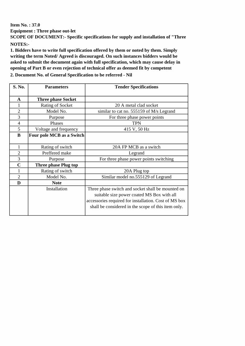
Item No. : 37.0
NOTES:-
S. No. Parameters Tender Specifications
A Three phase Socket
1 Rating of Socket 20 A metal clad socket
2 Model No. similar to cat no. 555159 of M/s Legrand
3 Purpose For three phase power points
4 Phases TPN
5 Voltage and frequency 415 V, 50 Hz
B Four pole MCB as a Switch
1 Rating of switch 20A FP MCB as a switch
2 Preffered make Legrand
3 Purpose For three phase power points switching
C Three phase Plug top
1 Rating of switch 20A Plug top
2 Model No. Similar model no.555129 of Legrand
D Note
Installation Three phase switch and socket shall be mounted on
suitable size power coated MS Box with all
accessories required for installation. Cost of MS box
shall be considered in the scope of this item only.
Equipment : Three phase out-let
SCOPE OF DOCUMENT:- Specific specifications for supply and installation of "Three
phase out-let"
1. Bidders have to write full specification offered by them or noted by them. Simply
writing the term Noted/ Agreed is discouraged. On such instances bidders would be
asked to submit the document again with full specification, which may cause delay in
opening of Part B or even rejection of technical offer as deemed fit by competent
authority.2. Document No. of General Specification to be referred - Nil
46

Item No. : 38.0
Notes:
S. No. Parameter Tender Specification
1 Data points
1.1 Preferred make Systimax/ Belden/ Tyco/Digilink
(Schneider)/Legrand
1.2 Type RJ 45 (Unshielded twisted pair, category 6,
TIA / EIA 568-B.2 )
1.3 Durability
1.3.1 Jack Minimum 750 mating cycles
1.3.2 Wire terminal Allow for a minimum of 200 terminations
without signal degradation below standard
compliance limits.
1.4 Contact material Contact material : Copper Alloy / Phosphor
bronze , plated with 50 micro-inches of
thick gold
1.5 Contact resistance 1mOhm (maximum)
1.6 Insulation resistance 500MOhm (minimum)
1.7 Strain relief caps Rear protective strain relief caps with side
or rear entry, to be installed onto cable
before or after termination
1.8 Connector 310 style insulation displacement
connectors with quadrant pair isolation and
a Pyramid wire entry system
1.9 Approvals UL
1.1 Wiring standard T568A or T568B
1.11 Cat6 Cable termination With a single conductor impact tool
1.12 Identification Color-coded snap-in icons for circuit
identification, category markings on front
and rear of outlet
1.13 Operating Temperature -10°C to 60°C
1.14 Number of information outlets for
various types of face plates.
1 No.
2 End boxes
Supply and installation of MS/modular
box is not in the scope of this item.
2.1 Material of box Cadmium passivated modular type
m.s./PVC box
Equipment : Data points
SCOPE OF DOCUMENT:- Specific specifications for supply, instalation, testing,
commissioing of ' Data points'
1. Bidders have to write full specification offered by them or noted by them. Simply
writing the term Noted/ Agreed is discouraged. On such instances bidders would be asked
to submit the document again with full specification, which may cause delay in opening of
Part B or even rejection of technical offer as deemed fit by competent authority.
2. General specification to be followed from Document No.: Nil
3. Makes other than indicated below are subject to approval by BARC
47

2.2 Thickness of box 2 mm
2.3 Size of box 2 Module
2.4 Installation Concealed/ Exposed in wall, column as per
Approved layout drawing.
3 Faceplate (Cover plate) Supply and installation of Face plate is
in the scope of this item
3.1 Preferred make Systimax/ Belden/ Tyco/Digilink
(Schneider)/Legrand
3.2 Type Shrouded
3.3 Number of ports 1 No.
3.4 Material ABS / UL 94 V-0
4 Excluded from scope of this item. These are covered in separate items of
price schedule. Hence cost of these items
shall not be included in the quoted rates of
this item.
4.1 Patch cords NA
4.2 Telephone cable NA
4.3 Optical fibre cable NA
4.4 Network racks NA
4.5 Telephone distribution frames NA
4.6 Jack panels NA
4.7 Fibre patch panels (LIU) NA
4.8 Active components NA
48

Item Nos :39 & 40
Notes:
S. No. Parameter Specified by BARC
1 Preferred make Systimax/ Digilink(Schneider)/ Tyco
2 Type Unshielded twisted pair, category 6, TIA /
EIA 568-B.2
3 Conductors 23 AWG solid bare copper or better
4 Insulation Polyethylene
5 Jacket LSZH flame retardant PVC
6 Pair Separator Cross-member fluted spine.
7 Approvals UL Listed, ETL verified to TIA / EIA Cat 6
8 Operating temperature -20 Deg. C to +60 Deg. C
9 Frequency tested up to Minimum 250 MHz
10 Packing Box of 305 meters
11 Delay Skew 45ns MAX.
12 Impedance 100 Ohms + / - 15 ohms, 1 to 600 MHz.
13 Performance characteristics to be
provided along with bid
13.1 Insertion @ 100m Loss (dB) 19.6 at 100 MHz: 28.7 at 200 MHz: 32.6 at
250 MHz: 36.1 at 300 MHz
13.2 NEXT Loss (dB) 47.3 at 100 MHz: 42.8 at 200 MHz: 41.3 at
250 MHz: 40.1 at 300 MHz
13.3 PSNEXT Loss (dB) 45.3 at 100 MHz: 40.8 at 200 MHz: 39.3 at
250 MHz: 38.1 at 300 MHz
13.4 ELFEXT @ 100m (dB) 30.8 at 100 MHz: 24.8 at 200 MHz: 22.8 at
250 MHz: 21.2 at 300 MHz
13.5 PSELFEXT @ 100m (dB) 28.8 at 100 MHz: 22.8 at 200 MHz: 20.8 at
250 MHz: 19.2 at 300 MHz
13.6 Return Loss @ 100m (dB) 21.1 at 100 MHz: 19 at 200 MHz: 18.3 at
250 MHz: 17.8 at 300 MHz
13.7 Propagation Delay @ 100m (ns) 518 at 100 MHz: 516 at 200 MHz: 516 at
250 MHz: 515 at 300 MHz
13.8 Delay Skew @ 100m (ns) 35 at 100 MHz: 35 at 200 MHz: 35 at 250
MHz: 35 at 300 MHz
14 Route From nearest Jack panel of same service to
the information outlets.
15 No. of cables 1 number
16 Installation and Termination Through existing conduits/casing
caping/pipes/trunking etc and 60 nos.
termination with all required accessories.
One end of cat6 cable shall be terminated
in Data/telephone points and other end
shall be terminated in jack panel/patch
panel/TTB.
Equipment : Cat-6 cable and termination
SCOPE OF DOCUMENT:- Specific Specifications for supply, installation, testing and
termination of "Cat-6 UTP cable"
1. Bidders have to write full specification offered by them or noted by them. Simply
writing the term Noted/ Agreed is discouraged. On such instances bidders would be asked
to submit the document again with full specification, which may cause delay in opening of
Part B or even rejection of technical offer as deemed fit by competent authority.
2. General specification to be followed from Document No.: Nil
3. Makes other than indicated below are subject to approval by BARC
49

Item No. : 41.0
Notes:
S. No. Parameter Tender Specification
1 Information outlets
1.1 Preferred make Systimax/ Belden/ Tyco/Digilink
(Schneider)
1.2 Type Unshielded Twisted Pair, Category 6, TIA /
EIA 568-B.2 (RJ11)
1.3 Durability
1.3.1 Jack Minimum 750 mating cycles
1.3.2 Wire terminal Allow for a minimum of 200 terminations
without signal degradation below standard
compliance limits.
1.4 Contact material Contact material : Copper Alloy / Phosphor
bronze , plated with 50 micro-inches of
thick gold
1.5 Contact resistance 1mOhm (maximum)
1.6 Insulation resistance 500MOhm (minimum)
1.7 Strain relief caps Rear protective strain relief caps with side
or rear entry, to be installed onto cable
before or after termination
1.8 Connector 310 style insulation displacement
connectors with quadrant pair isolation and
a Pyramid wire entry system
1.9 Approvals UL
1.1 Wiring standard T568A or T568B
1.11 Cat6 Cable termination With a single conductor impact tool
1.12 Identification Color-coded snap-in icons for circuit
identification, category markings on front
and rear of outlet
1.13 Operating Temperature -10°C to 60°C
1.14 Number of outlet. 1 No.
2 End boxes Supply and installation of MS/modular box
is not in the scope of this item
2.1 Material of box Cadmium passivated modular type m.s. box
2.2 Thickness of box 2 mm
2.3 Size of box 2 Module
Equipment : RJ11 Telephone Point
SCOPE OF DOCUMENT:- Specific specifications for supply, instalation, testing,
commissioing of ' RJ-11 Telphone points'
1. Bidders have to write full specification offered by them or noted by them. Simply
writing the term Noted/ Agreed is discouraged. On such instances bidders would be asked
to submit the document again with full specification, which may cause delay in opening of
Part B or even rejection of technical offer as deemed fit by competent authority.
2. General specification to be followed from Document No.: Nil
3. Makes other than indicated below are subject to approval by BARC
50

2.4 Installation Concealed/ Exposed in wall, column as per
Approved layout drawing.
3 Faceplate (Cover plate) Supply and installation of Face plate is
in the scope of this item
3.1 Preferred make Systimax/ Belden/ Tyco/Digilink/Legrand
(Schneider)
3.2 Type Shrouded
3.3 Number of ports 1 No.
3.3 Material ABS / UL 94 V-0
51

Item No. 42.0 :
S. No. Parameter Tender Specification
1 Type of Addressable Multisensor
Detector
Combination of Smoke detection and heat
detection. The smoke detection system
shall carried by 2 optical elements and the
Heat detection system shall be of Rate of
rise of temperature and Fixed
Temperature.
2 Preferred Manufactures Bosch. To be installed in existing Bosch
Make fire alarm system. Existing detector
model no. FAP-425-DOT-R
3 Standard & Approvals Confine to the EN54 or UL/ULC/ VdS/FM
4 Sensitivity In accordance with EN54-29 and The
sensitivity shall be field settable
5 Power supply and addressing Loop powered and addressed through
Programming from the Panel.
6 Display Visible multi color LED to indicate the
healthiness/trouble/alarm condition of the
detector. The LED shall be located in
such a way that it shall be visible from all
the 360 degree from below
7 Isolation Inbuilt fault isolators
8 Other Features
8.1 False alarm immunity and a superior
signal to noise ratio
Required
8.2 Built in signal processor Required
8.3 Drift compensation facility built in Required
8.4 Panel shall allow to replace the
detector with the same type without the
need of additional programming
Required
8.5 programmed to work as Optical only or
Thermal only detectors. It shall a
provision to switch off any component
(optical or thermal) of the detector
Required
8.6 Capable of detecting both smoldering
fires and open fires
Required
8.7 Type of fires shall be covered as per
EN-54-29
TF-1 to TF-5
9 Inspection & Testing Functionality test shall be carried out at
manufacturer's works or at dealer/firm lab.
10 Notes for installation
Multi sensor smoke detector: FA detector with dual optical and thermal element( i.e.
capable of detecting fire type TF1 to TF5 reliably as defined in EN-54-29) as per below
tender specifications.
52

10.1 MS box fabricated out of 2 mm thick ms
sheet duly powder coated after seven tank
treatment for termination of cable (Approx.
size 120mmx120mmx70 mm)
Cost of ms box to be included in the cost
of detector
11 Testing and commissioning at site Functional test shall be carried out at site.
53

S. No. Parameter Tender Specification
1 Type of Response indicators Visual indicating type and shall start flashing
when the detector in that particular' area / zone
has been activated due to smoke or fire and
LED's of the response indicators shall be
housed on aesthetically designed MS bases.
2 Preferred Manufactures Bosch. To be installed in existing Bosch Make
fire alarm system.
3 Display Give repeat indication of the particular detector
state
4 Inspection & Testing Functionality test shall be carried out at
manufacturer's works or at dealer/firm lab.
5 Notes for installation
5.1 MS box fabricated out of 2 mm
thick ms sheet duly powder coated
after seven tank treatment for
termination of cable (Approx. size
100mmx100mmx100 mm)
Cost of ms box if required to be included in the
cost of detector
5.2 Testing and commissioning at site Functional test shall be carried out at site.
Item No.43.0: Respoance Indicator : Supply, installation, testing and commissioning of
response indicator as per below specification.
54

पृष्ठ संख्या 1 / 3
Annexure V
तकनीकी विवनरे्दश (Technical Specifications)
LABORATORY ITEMS
Item No. 44.0: Laboratory Wall Table
The scope of this clause is Design, fabrication, supply & installation of Stainless Steel tables with 12 mm thick
phenolic/acid resistant clean room compatible sheet over SS 304 top. The table shall be equipped with good quality lock,
SS handles etc. and for proper rigidity, suitable SS angle shall be provided wherever required. The table’s legs shall be
constructed out of 1.5 mm SS 304 material & size - dimensions of the table shall be as per site space availability. The
contractor shall provide a drawing of the table to the department and fabrication should start after getting approval.
Item No. 45.0: Vertical air flow unit - Class 100
Design
Design basis of Vertical Laminar Air Flow unit as per Cleanroom standards
Construction
Manufactured the VLAF in SS 304 construction. Thickness of the SS 304 sheet is approx. 1.00 mm thick.
Filtration System
VLAF is having pre filters to maintain the quality & life of final filters. Final filter is HEPA filter as per the design
and flow of the unit.
Blower & Motor
VLAF is supplied with centrifugal Blower with Electric Motor as per the Design & Air flow of the unit along with
all required cabling. The system is designed to maintain Laminar Air Flow over the working table with Designated
Velocity.
Work Table Top
Working Table top is constructed in SS 304 with thick phenolic/acid resistant clean room compatible sheet over it
& Gas Cock with necessary arrangements.
Magnehelic Gauge & DOP Port
VLAF is supplied with mangnehelic Port & gauge for differential Pressure monitoring and DOP port provision at
the time of validation.
Side Glass
VLAF is provided with Toughened Glass as a side protection of the Unit
Lighting & Electrical Utilities
White light for proper illumination for work table top & with power supply Socket, cabling & switches.
UV light & Hour meter
VLAF shall be equipped with UV light and calibrated Hour meter as a part of the system
Levelling Legs and Wheels
VLAF is designed & supplied with Caster wheel for smooth movement & Levelling legs for the Height Adjustment
Dimension:
VLAF working space size should be approx.- Width 3.5 feet, Length: 5 feet, Height: 4 feet and as per site space
suitability.
Class 100:
VLAF is designed & supplied with HEPA filter to maintain Class 100 on working table.

पृष्ठ संख्या 2 / 3
Other Features of Vertical Laminar Flow unit
1. Format: Free-Standing
2. Filter Alarm: Automatic Alarm System
(Free-standing vertical laminar flow stations include a programmable filter back-pressure alarm that is integrated
into a touch-screen PLC panel. This should allow control of the differential pressure set-point to adjust frequency
of filter replacement. It should include a visual differential pressure gauge, visual flashing indicator light, and an
audible buzzer with silencer that sounds when set point level is exceeded)
3. Work Surface: Vibration Isolated
4. Frame Material: 304 Stainless Steel
5. Side Panels: Interchangeable Plastic Side Panels
Removable side-panels for increasing the versatility of hood by improving visibility and/or simplifying equipment
access and maintenance. The side-panels are lined with foam gasket and slide into the hood’s frame for a simple yet
effective sealed fit, free of troublesome fasteners or screws.
(the material should have Visibility, Light sensitivity, Electrostatic discharge (ESD) safety, Chemical resistance,
Thermal extremes)
Material type: Static-Dissipative PVC (SDPVC)
7. Energy-Efficient EC FFUs: Energy efficient FFUs offering precision control of fan speed.
8. Room-Side Filter Replacement: Room-side replaceable (RSR) filters for easy removal and replacement
disassembling the bulky FFU from the hood. RSR filters should feature a gel-seal to form a tight seal against the
"knife-edge" on the blower housing.
9. Explosion/fire-Proof Design:
An explosion-proof laminar flow hood for work in hazardous areas with risk of ignition due to flammable fumes or
explosive dusts. All electrical components in explosion-proof hood designs shall be rated compliant for fire etc.
The system shall be complete with above features & Utility Valves etc. The contractor shall provide a General arrangement
drawing of this unit to the department and fabrication should start after getting approval. Once fabricated, the unit shall
be inspected at manufacturer’s works.
The cost of all above including accessories shall be included under the cost of this item. No extra payment shall be made
for the same.
Item No. 46.0 : Fume Hood Chamber
1. DESIGN
Fume Hood Chamber With Manually Operated Sash (Door) shall be of By pass type, Floor mounted,
Aerodynamic Design Structure
2. CONSTRUCTION
Exterior & Interior - Super High density 12mm thick phenolic resin sheet / acid resistant clean room
compatible
sheet, the colour combination as per the client, With Pillars in front for Utilities made of SS 304.
3. SUCTION & EXHAUST ARRANGEMENT
3-point suction system for light, normal & heavy fumes with baffle to ensure smooth and immediate
exhaust of fumes. Flush air foil mounted on the worktop
4. WORK TABLE TOP
Chemical & Stain Poof, rust, splash & spillage proof work top. Super high gloss, super jet-Black
Ceramic table top.
5. SASH (DOOR)
Frame less Vertical rising counter- up down movement. Safety Glass’ sash Smooth and light sash
operation. Shutter will be very smooth.
6. LIGHTING & ELECTRICAL UTILITIES

पृष्ठ संख्या 3 / 3
LED light (16 Watt, 2 nos.) with acid resistant cover for proper illumination for work table top with 2
no’s Industrial Switch socket OR 2 no’s of Anchor Roma Switches
7. WET & DRY UTILITIES
Remotely operated gas & water valve in the front facia of the fume hood with nozzle for the output of
1 no. of Water, 2 no’s of Gas Point (Air, Nitrogen)
8. APPARATUS STORAGE CABINATE
Hinge less door of storage cabinet, Shutters are fixed with the help of Pivot, made with SS 304.There
will be provision for 3 Drawers on one side & shutters on other side of the base storage.
9. LEVEL ADJUSTING SCREWS
To adjust fume hood level by +/- 10mm.
10. PP TRAYS
Three PP Tray will be provided for keeping the acid bottles in the Basement Storage
11. CENTRIFUGAL BLOWERS- AIR SUCTION IN FUME HOOD
SISW type, chemical & heat resistant PP + FRP blower with one piece molded sturdy PP impeller, with
drain plug. It’s a very silent High efficiency Blower –motor. Blower CFM confirming to international
face velocity norms and as per fume hood airflow pattern. For 1fume hood: 800 CFM approx. confirming to
international face velocity norms and as per fume hood air flow pattern.
Electric motor – for Fume hood ‘ISI’ approved Motor (3 phase), direct drive, continuous rating. As per
IS 325., It will be of approx. 0.75 H.P.
12. SIZE OF THE FUME HOOD
DIMENSIONS (Approx.)- Length-1250 X Depth-900x Height 2250 and as per site suitability.
WORKING AREA (Approx.)- Length-1050 X Depth-850*Height 2250 and as per site suitability.
The system shall be complete with above features & Utility Valves etc. The Fume Hood shall be interlinked with
Condensing unit (3 TR). All Power and control cabling for interlinking shall be in the scope of the contractor. The
contractor shall provide a General arrangement drawing of this unit to the department and fabrication should start after
getting approval. Once fabricated, the unit shall be inspected at manufacturer’s works.
The cost of all above including accessories shall be included under the cost of this item. No extra payment shall be made
for the same.
Item No. 47.0 : Service Shelves
The scope of this clause includes fabrication & supply of the framework of 1.2 mm thick Stainless Steel sheet in 2 tiers
with retaining lips, 6 mm epoxy resin lining and electrical sockets with fire retardant wiring. The contractor shall provide
a General arrangement drawing of this unit to the department and fabrication should start after getting approval.
The cost of all above including accessories shall be included under the cost of this item. No extra payment shall be made
for the same.
Item No. 48.0 : Fume Hood Ducting
Fabrication & installation of suitable rigidity PP FRP Ducting from Fume Hood to exhaust stack point with horizontal,
vertical member, flanges, and bends, bracketed supports. Bends, Tees, & Reducers etc. The ducting shall be suitably
supported through MS structure (Paid under separate item).
Item No. 49.0 : FRP Damper
Fabrication, supply & installation of PP FRP damper with suitable sized actuator motor interlocked with Fume hood
blower. The damper shall open & close as the blower of Fume hood opens & closes. The interlinking involving power
& control cabling shall be in the scope of the contractor under this item.
Related Documents


