Reduced Safety Flaring through Advanced Control 31 st Industrial Energy Technology Conference – New Orleans, LA David Hokanson – ExxonMobil Chemical Keith Lehman – Empirical Process Solutions S. Matsumoto – Tonen Chemical N. Takai – Tonen Chemical F. Takase – TonenGeneral May 20, 2010

Reduced Safety Flaring through Advanced Control 31 st Industrial Energy Technology Conference – New Orleans, LA David Hokanson – ExxonMobil Chemical Keith.
Dec 15, 2015
Welcome message from author
This document is posted to help you gain knowledge. Please leave a comment to let me know what you think about it! Share it to your friends and learn new things together.
Transcript

Reduced Safety Flaring through Advanced Control
31st Industrial Energy Technology Conference – New Orleans, LA
David Hokanson – ExxonMobil ChemicalKeith Lehman – Empirical Process SolutionsS. Matsumoto – Tonen ChemicalN. Takai – Tonen ChemicalF. Takase – TonenGeneral
May 20, 2010
2
Outline
• Problem Statement
• Plant Fuel Gas System Overview
• Solution
• Results
• Summary

3
Problem Statement
• Reduce / eliminate fuel gas releases to safety flare system
• Stabilize fuel gas molecular weight to olefins furnaces
• Major issueAverage molecular weight of Fuel Gas is much different than fuel gas
make-up from propane / butane vaporizers
When demand / supply changes, change in propane/butane make-up causes system to cycle, causing a release to the safety flare system

4
Fuel Gas System Overview
HP Fuel Gas
Unit1
GTG
Off- Gas
SC
BB/ PropaneVaporizers
Unit2
Unit6Unit5Unit4Unit3Unit1
Crude Fuel Gas
HP BB Gas
Dry Fuel Gas
Customers
PIC
Unit7
Town Gas
Unit8
LP BB / C3 GasPIC
Sphere
Unit9
LP Fuel Gas
FLARE
PIC
FLARE
PIC
C kPaG
D kPaG
B kPaG
BB/ PropaneVaporizers
PIC
A kPaG
A kPaG
5
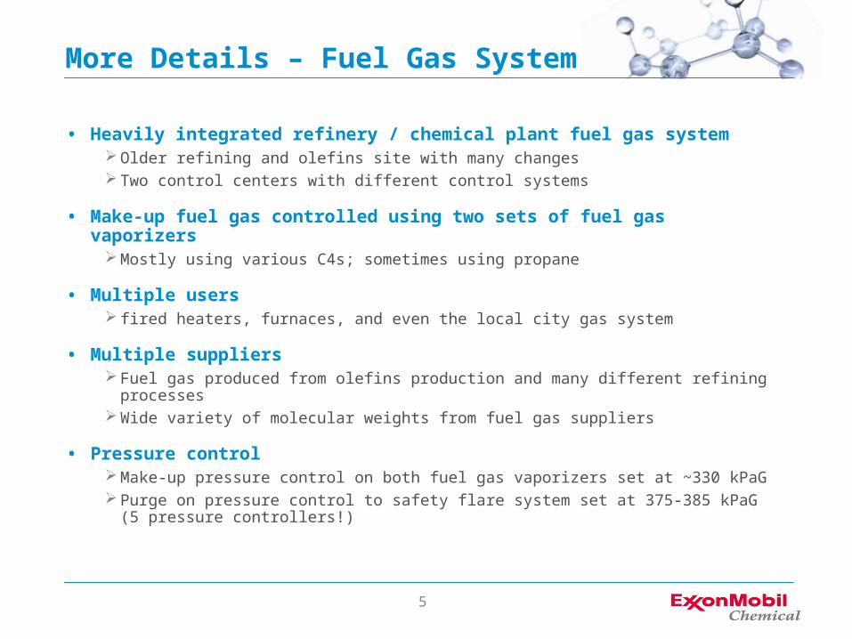
More Details – Fuel Gas System
• Heavily integrated refinery / chemical plant fuel gas system Older refining and olefins site with many changes Two control centers with different control systems
• Make-up fuel gas controlled using two sets of fuel gas vaporizers Mostly using various C4s; sometimes using propane
• Multiple users fired heaters, furnaces, and even the local city gas system
• Multiple suppliers Fuel gas produced from olefins production and many different refining processes Wide variety of molecular weights from fuel gas suppliers
• Pressure control Make-up pressure control on both fuel gas vaporizers set at ~330 kPaG Purge on pressure control to safety flare system set at 375-385 kPaG (5 pressure
controllers!)

6
Solution• Develop a thorough understanding of the process
Developed detailed flow diagram of entire refining / chemical plant fuel gas system Used plant historical data to understand / model fuel gas changes due to changes in make-up flows
• Develop model-based advanced controller for the overall process Used DMCplusTM from AspenTech Basic DMCplus Design
Keep pressure control to flare valves in-place Use DMCplus to manipulate make-up from fuel gas vaporizers and cat cracker fuel gas flow
• Execute Pre-Test Confirm DMCplus design; obtain initial dynamic models for manipulated variables
Manipulated variables = plant variables such as flow setpoints or valves moved by DMCplus Collect additional data on fuel gas suppliers and users that will be “feed forward variables” to the
controller Design detail: Use “calculated heating value” for all fuel gas input streams and users to
develop pressure models
• Execute Plant Test / Commission Controller Utilized AspenTech’s SmartStepTM automated tester with in-house developed methodology to test and
commission the controller at the same time Testing and commissioning lasted 7 days
• Final DMCplus controller size 6 manipulated variables 13 controlled variables 46 feed-forward variables
7
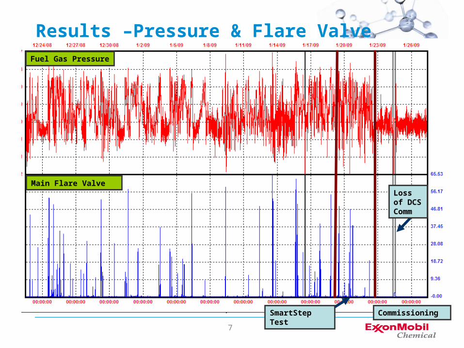
Results –Pressure & Flare Valve
Main Flare Valve
Fuel Gas Pressure
SmartStep Test Commissioning
Loss of DCS Comm

8
Results – FG Mol Weight
SmartStep Test Commissioning
Loss of DCS Comm
Tight Control of Olefins MW without impacting MW of other users
Olefins Furnace Mol Weight
BH Mol Weight
Fuel Gas Mol Weight
9
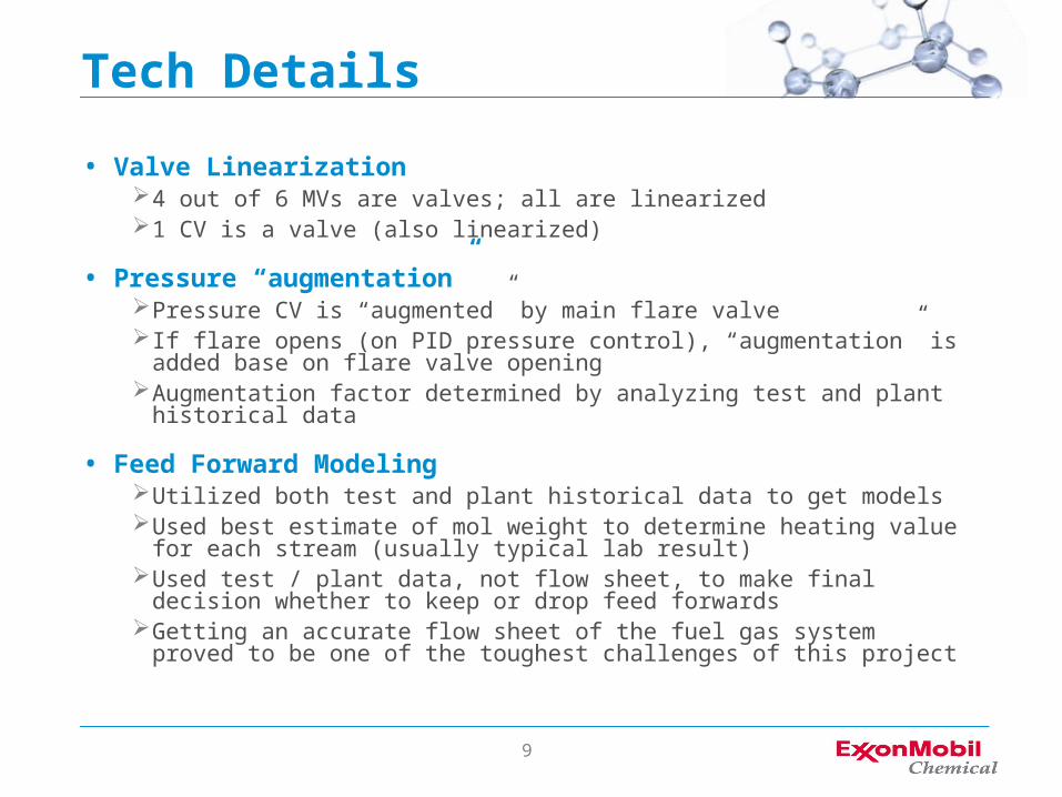
Tech Details
• Valve Linearization4 out of 6 MVs are valves; all are linearized1 CV is a valve (also linearized)
• Pressure “augmentation”Pressure CV is “augmented” by main flare valveIf flare opens (on PID pressure control), “augmentation” is added base on
flare valve openingAugmentation factor determined by analyzing test and plant historical data
• Feed Forward ModelingUtilized both test and plant historical data to get modelsUsed best estimate of mol weight to determine heating value for each stream
(usually typical lab result)Used test / plant data, not flow sheet, to make final decision whether to keep
or drop feed forwardsGetting an accurate flow sheet of the fuel gas system proved to be one of the
toughest challenges of this project
10
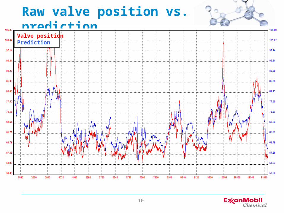
Raw valve position vs. predictionValve positionPrediction

11
Linearized valve position vs. predictionValve positionPrediction
12
Summary
• Successful Fuel Gas DMC CompletedFuel Gas pressure controlled tightly
No fuel gas to flare when DMC is on control
Mol weight and other constraints obeyed / tightly controlled
Credits estimated by reducing C4s to flare by 75%(vs excellent 2008 operation)
• Actual reduction to date has been bigger than this estimate Continued little/no loss of fuel gas to flare when DMC is on control
©2010 ExxonMobil. To the extent the user is entitled to disclose and distribute this document, the user may forward, distribute, and/or photocopy this copyrighted document only if unaltered and complete, including all of its headers, footers, disclaimers, and other information. You may not copy this document to a Web site. ExxonMobil does not guarantee the typical (or other) values. Analysis may be performed on representative samples and not the actual product shipped. The information in this document relates only to the named product or materials when not in combination with any other product or materials. We based the information on data believed to be reliable on the date compiled, but we do not represent, warrant, or otherwise guarantee, expressly or impliedly, the merchantability, fitness for a particular purpose, suitability, accuracy, reliability, or completeness of this information or the products, materials, or processes described. The user is solely responsible for all determinations regarding any use of material or product and any process in its territories of interest. We expressly disclaim liability for any loss, damage, or injury directly or indirectly suffered or incurred as a result of or related to anyone using or relying on any of the information in this document. There is no endorsement of any product or process, and we expressly disclaim any contrary implication. The terms, “we”, “our”, "ExxonMobil Chemical", or "ExxonMobil" are used for convenience, and may include any one or more of ExxonMobil Chemical Company, Exxon Mobil Corporation, or any affiliates they directly or indirectly steward. ExxonMobil, the ExxonMobil Logo, the Interlocking "X” Device, and all other product names used herein are trademarks of ExxonMobil unless indicated otherwise.
“DMCPlus” and “SmartStep” are trademarks of Aspen Technology, Inc.
Related Documents