INSTALLATION AND SERVICE MANUAL Models DA12A DA12L DA24A DA24L DA36A DA36L

Welcome message from author
This document is posted to help you gain knowledge. Please leave a comment to let me know what you think about it! Share it to your friends and learn new things together.
Transcript
INSTALLATION AND SERVICEMANUAL
ModelsDA12A DA12LDA24A DA24LDA36A DA36L

Warranty Policy Instruction and Service Manual
Pacific Scientific REDI-LINE Generators
Warranty PolicyPacific Scientific warrants its REDI-LINE Generator to the original purchaser and inthe case of original equipment manufacturers or distributors, to their originalconsumer, to be free from defects in material and workmanship. In no event,however, shall Pacific Scientific be liable or have any responsibility under suchwarranty if the products have been improperly stored, installed, used or maintained,or if customer has permitted any unauthorized modifications, adjustments and/orrepairs to such products.
Pacific Scientific obligation hereunder is limited solely to repairing or replacing (at itsoption), at its factory any products, or parts thereof, which prove to our satisfactionto be defective as a result of defective materials or workmanship, in accordancewith our stated warranty, provided however, that the written notice of claimeddefects shall be given to Pacific Scientific within two (2) years after the date of theproduct date code that is affixed to the product, and within thirty (30) days from thedate any such defect is first discovered. This warranty does not include brush orcommutator wear since wear is normal.
The products or parts claimed to be defective must be returned to Pacific Scientific,or an Authorized REDI-LINE distributor, transportation prepaid by customer, with adetailed written explanation of the claimed defect. Evidence acceptable to PacificScientific must be furnished that the claimed defects were not caused by misuse.abuse. or neglect by anyone other than Pacific Scientific.
The foregoing warranties are in lieu of all other warranties (except as to title),whether expressed or implied, including without limitation, any warranty ofmerchantability or of fitness for any particular purpose, and are in lieu of all otherobligations or liabilities on the part of Pacific Scientific. Pacific Scientific's maximumliability with respect to these warranties, arising from any cause whatsoever,including without limitation, breach of contract, negligence, strict liability, tortwarranty, patent or copyright infringement, shall not exceed the price specified ofthe products giving rise to the claim, and in no event shall Pacific Scientific be liableunder these warranties or otherwise, even if Pacific Scientific has been advised ofthe possibility of such damages, for special, incidental, or consequential damages,including without limitation, damage or loss resulting from inability to use theproducts, increased operating costs resulting from a loss of the products, loss ofanticipated profits, or other special, incidental, or consequential damages, whethersimilar or dissimilar, of any nature arising or resulting from the purchase, installation,removal, repair, operation, use or breakdown of the products, or any other causewhatsoever, including negligence.
The forgoing shall also apply to products, or parts for the same which have beenrepaired or replaced pursuant to such warranty, and within the period of time, inaccordance with Pacific Scientific's date of warranty.
No person, including any agent, distributor, or representative of Pacific Scientific, isauthorized to make any representation or warranty on behalf of Pacific Scientificconcerning any products or programs manufactured by Pacific Scientific, except torefer purchases to this warranty.
Instruction and Service Manual Table of Contents
Pacific Scientific REDI-LINE Generators
TABLES OF CONTENTS
ABOUT THIS MANUAL .......................................................................................................................... 5
1. DESCRIPTION AND OPERATION ................................................................................................... 6
FEATURES .................................................................................................................................................... 6
2. GENERAL SPECIFICATIONS ........................................................................................................... 7
NAMEPLATE DATA ...................................................................................................................................... 7
3. UNPACKING ......................................................................................................................................... 8
UNPACKING ................................................................................................................................................. 8
4. PREPARATION FOR INSTALLATION ............................................................................................ 9
CHOOSING AN ACCEPTABLE LOCATION ................................................................................................... 9DETERMINING INSTALLATION REQUIREMENTS ..................................................................................... 10BATTERY SELECTION ............................................................................................................................... 17WIRING CONSIDERATIONS ....................................................................................................................... 18
5. INSTALLATION ................................................................................................................................. 19
BEFORE BEGINNING INSTALLATION........................................................................................................ 19MOUNTING................................................................................................................................................. 19INSTALLATION INTERCONNECTION ......................................................................................................... 20INSTALLATION CHECKOUT ...................................................................................................................... 23
6. MAINTENANCE ................................................................................................................................. 24
CLEANING .................................................................................................................................................. 24MOUNTING AND ELECTRICAL CONNECTIONS ........................................................................................ 24BRUSHES .................................................................................................................................................... 24COMMUTATORS......................................................................................................................................... 24
Table Of Contents Instruction and Service Manual
4 Pacific Scientific REDI-LINE Generators
7. FIELD TROUBLESHOOTING ......................................................................................................... 25
FIELD SERVICE .......................................................................................................................................... 25USE OF FLOW CHARTS.............................................................................................................................. 25CONDITIONAL BRANCHES ........................................................................................................................ 25ADDITIONAL TROUBLESHOOTING AND REPAIR...................................................................................... 25SHOULD YOU NEED TO RETURN THE UNIT ............................................................................................. 26FIELD TROUBLESHOOTING CHECKLIST FORM....................................................................................... 27TROUBLESHOOTING FLOW CHARTS........................................................................................................ 28OTHER TROUBLESHOOTING CHECKS...................................................................................................... 38
8. BENCH TROUBLESHOOTING ....................................................................................................... 39
USE OF FLOW CHARTS.............................................................................................................................. 39CONDITIONAL BRANCHES ........................................................................................................................ 39ASSEMBLY AND DISASSEMBLY................................................................................................................. 39TROUBLESHOOTING FLOWCHARTS ......................................................................................................... 40TROUBLESHOOTING CHECKOUT PROCEDURES...................................................................................... 44
9. REPAIR PROCEDURES .................................................................................................................... 52
GENERAL ................................................................................................................................................... 52RECOMMENDED TOOLS AND EQUIPMENT............................................................................................... 52DISASSEMBLY OF SMALL FRAME UNITS ................................................................................................. 53RE-ASSEMBLY OF SMALL FRAME UNITS................................................................................................. 54DISASSEMBLY OF LARGE FRAME UNITS ................................................................................................. 55RE-ASSEMBLY OF LARGE FRAME UNITS................................................................................................. 56DC BRUSH REMOVAL AND REPLACEMENT............................................................................................. 57CHECKOUT AFTER REPAIR....................................................................................................................... 58
10. PARTS LISTS ..................................................................................................................................... 59
MODELS COVERED.................................................................................................................................... 59PARTS LIST CONVENTIONS....................................................................................................................... 59
11. TECHNICAL DATA .......................................................................................................................... 92
PERFORMANCE CURVES ........................................................................................................................... 92

Instruction and Service Manual About This Manual
Pacific Scientific REDI-LINE Generators 5
ABOUT THIS MANUAL
The purpose of this manual is twofold: first, to provide comprehensive installationinstructions for Pacific Scientific REDI-LINE generators; and second, to providecomprehensive maintenance, troubleshooting, and repair procedures.
It is imperative that the installation instructions be followed closely. Successfulinstallation depends upon a number of factors, and ignoring any one factor can leadto major problems with the unit.
Troubleshooting has been divided into three sections, the first for isolatinginstallation problems, the second for identifying problems with the unit itself while inthe field, and the third for isolating problems requiring bench repair. The owner orinstaller should initially undertake troubleshooting. Careful troubleshooting caneliminate installation problems and help avoid having to return the unit to the dealer.Bench troubleshooting is for dealer or factory use, and should not be used in thefield.
Technical data contained in the manual is for dealer reference.

Description and Operation Instruction and Service Manual
6 Pacific Scientific REDI-LINE Generators
1. DESCRIPTION AND OPERATION
The REDI-LINE Generator is an electromechanical device that converts DC batterypower to AC power. The DC supply consists of one or more deep cycle batteriestypically added to a vehicle electrical system. Convenient, remote operation of mosttools, appliances and lighting is assured as long as power consumption is within thenameplate rating of the generator. The REDI-LINE generator is designed to supplyunregulated, true sine-wave electrical power for years of trouble free service.
The REDI-LINE Generator consists of a DC motor and an AC generator on acommon armature assembly. Speed of the DC motor, and, therefore, frequency ofthe AC generator varies within limits as the load and battery power levels vary. Theunit starts automatically when an electrical load is applied.
Figure 1. The Two Basic Versions of REDI-LINE Generators
Features
The following features recommend the REDI-LINE DC to AC generator to userswho have need of reliable AC power on service and recreational vehicles, or atremote sites.
• Built rugged and reliable with sturdy steel housing.
• Two year warranty.
• Patented Demand Start Circuitry extends battery life.
• Easily delivers peak output currents up to 1.5 times the continuous output ratingfor extra starting power.
• Conveniently mounts in any position in a minimum of space.
• True sine-wave output.
• Optional GFI outlet.
• Operates in ambient temperatures from -30°F to 104°F

Instruction and Service Manual General Specifications
Pacific Scientific REDI-LINE Generators 7
2. GENERAL SPECIFICATIONS
Nameplate Data
The generator nameplate provides the operational specifications of the generator.The beginning letter designations of the catalog listing describe the generator type.Additional data given on the nameplate includes the generator part number, inputdata, output data, insulation class, and serial number.
Table 1.1 General Specifications
Models DA12A-500A DA12L-1600A DA24A-800A DA24L-1600A DA36A-900A DA36L-1600A
Input Voltage (DC) 12 12 24 24 36 36
Nominal Input Voltage (DC) 12.6 12.6 25.2 25.2 37.8 37.8
Continuous Output Watts 500 1600 800 1600 900 1600
Surge Output Watts 750 2400 1200 2400 1350 2400
Output Voltage* (AC) 120 120 120 120 120 120
Output Frequency (Hz) 65 65 60 60 60 60
Continuous Output Current (Amps) 4.5 14.5 7.3 12.8 8.2 14.5
Surge Output Current (Amps) 7 22 11 20 12 22
Wave Shape Sine Sine Sine Sine Sine Sine
Length (inches) 16.25 16.75 16.25 15.13 16.25 15.13
Height (inches) 5.5 9.13 5.5 9.13 5.5 9.13
Diameter (inches) 5.18 7.38 5.18 7.38 5.18 7.38
Weight (lbs.) 26 53 26 48 26 48
** Variance from output voltage and frequency is dependent on load size and theDC input voltage. Typical voltage tolerance is ±15%. Typical frequency toleranceis ±5%. Carefully monitor any equipment that is sensitive to fluctuations in eithervoltage or frequency.

Unpacking Instruction and Service Manual
Pacific Scientific REDI-LINE Generators
3. UNPACKING
Unpacking
Open the box and lift out the Generator and the insert.
CAUTION: The generator is a piece of heavy equipment. Removing it from thebox may require more than one person to avoid dropping the generator andprevent personal injury.
Inspect the unit for any damage that may have been sustained during shipment. Ifyou find damage, contact the shipper immediately to file a claim.

Instruction and Service Manual Preparation for Installation
Pacific Scientific REDI-LINE Generators 9
4. PREPARATION FOR INSTALLATION
Most REDI-LINE service requests result from improperly installed units. Improperinstallation will affect generator performance and may damage the unit.
NOTE: Damage caused by incorrectly installing your REDI-LINE generator isnot covered by warranty.
Successful installation calls for proper planning, as well as the use of propermaterials during the installation process. Follow the procedures outlined below inpreparing for installation of your generator.
Choosing an Acceptable Location
Observe these guidelines when choosing a location to mount your generator and it’sbattery system.
Cable Routing
Keep the generator as close to the battery as possible to reduce the length of thepower cables. Long power cables will reduce the amount of voltage to thegenerator and decrease performance.
Carefully plan the power supply cable route. Do not allow the cables to rub againstsharp surfaces, which could cut the cable insulation and cause a short against thevehicle frame.
Accessibility
Be sure both the REDI-LINE generator and the battery system are located so thatthey are easily accessible for servicing.
Protection from Moisture
Do not install the generator or battery system in areas with direct exposure to water.Do not use a steam cleaner or a high-pressure washer around the generator unlessit is totally protected against water intrusion.
Protection from Damage
Be sure both the REDI-LINE generator and the battery system are installed in areaswhere they are not subject to damage.
Ventilation Considerations
Allow at least 2 inches of free air space around the REDI-LINE generator. Do notobstruct the ventilation as it can cause the generator to overheat. Install the batterysystem in an area that is ventilated, so that battery fumes can be readily dissipated.

Preparation For Installation Instruction and Service Manual
10 Pacific Scientific REDI-LINE Generators
CAUTION: Do not install the REDI-LINE generator and it’s supplybatteries in the same compartment.
CAUTION: Do not install the REDI-LINE generator in a compartment thatcould contain explosive fumes.
Determining Installation Requirements
Determine how frequently and at what loads you plan to use your generator. Findthe Redi-Line generator series you purchased and choose the correct installationdiagram based on your usage and loads. Use this diagram as a guide when itcomes time to do the system installation.
Instruction and Service Manual Preparation for Installation
Pacific Scientific REDI-LINE Generators 11
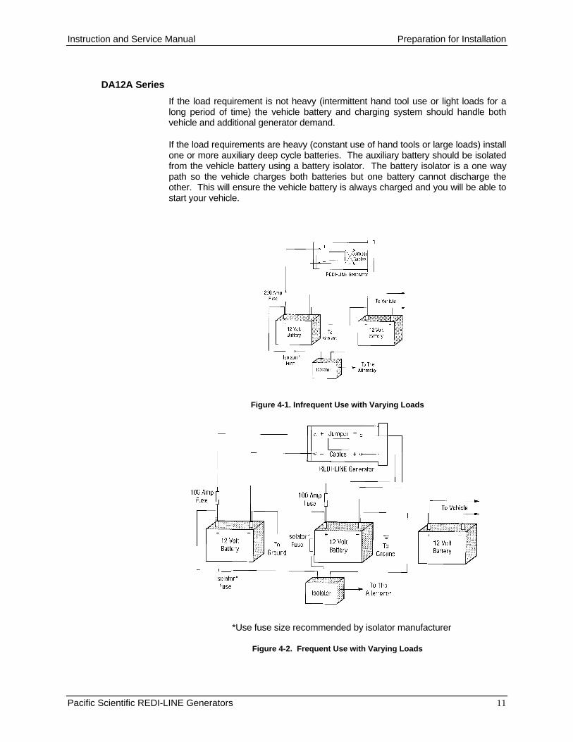
DA12A Series
If the load requirement is not heavy (intermittent hand tool use or light loads for along period of time) the vehicle battery and charging system should handle bothvehicle and additional generator demand.
If the load requirements are heavy (constant use of hand tools or large loads) installone or more auxiliary deep cycle batteries. The auxiliary battery should be isolatedfrom the vehicle battery using a battery isolator. The battery isolator is a one waypath so the vehicle charges both batteries but one battery cannot discharge theother. This will ensure the vehicle battery is always charged and you will be able tostart your vehicle.
Figure 4-1. Infrequent Use with Varying Loads
*Use fuse size recommended by isolator manufacturer
Figure 4-2. Frequent Use with Varying Loads

Preparation For Installation Instruction and Service Manual
12 Pacific Scientific REDI-LINE Generators
DA12L Series
If the load requirement is not heavy (intermittent hand tool use or light loads for along period of time) install one or more auxiliary deep cycle batteries. The auxiliarybattery should be isolated from the vehicle battery using a battery isolator. Thebattery isolator is a one way path so the vehicle charges both batteries but onebattery cannot discharge the other. This will ensure the vehicle battery is alwayscharged and you will be able to start your vehicle.
If the load requirements are heavy (constant use of hand tools or large loads) installtwo or more auxiliary deep cycle batteries. The auxiliary batteries should be isolatedfrom the vehicle battery using a battery isolator. The battery isolator is a one waypath so the vehicle charges both batteries but one battery cannot discharge theother. This will ensure the vehicle battery is always charged and you will be able tostart your vehicle.
Figure 4-3. Infrequent Use with Varying Loads
Figure 4-4. Frequent Use with Varying Loads

Instruction and Service Manual Preparation for Installation
Pacific Scientific REDI-LINE Generators 13
DA24A Series
If the load requirement is not heavy (intermittent hand tool use or light loads for along period of time) the vehicle battery and charging system should handle both thevehicle and additional generator demand.
If the load requirements are heavy (constant use of hand tools or large loads) installtwo or move deep cycle auxiliary batteries. The auxiliary battery should be isolatedfrom the vehicle battery using a battery isolator. The battery isolator is a one waypath so the vehicle charges both batteries but one battery cannot discharge theother. This will ensure the vehicle battery is always charged and you will be able tostart your vehicle.
Figure 4-5. Infrequent Use with Varying Loads
Figure 4-6. Frequent Use with Varying Loads
Preparation For Installation Instruction and Service Manual
14 Pacific Scientific REDI-LINE Generators
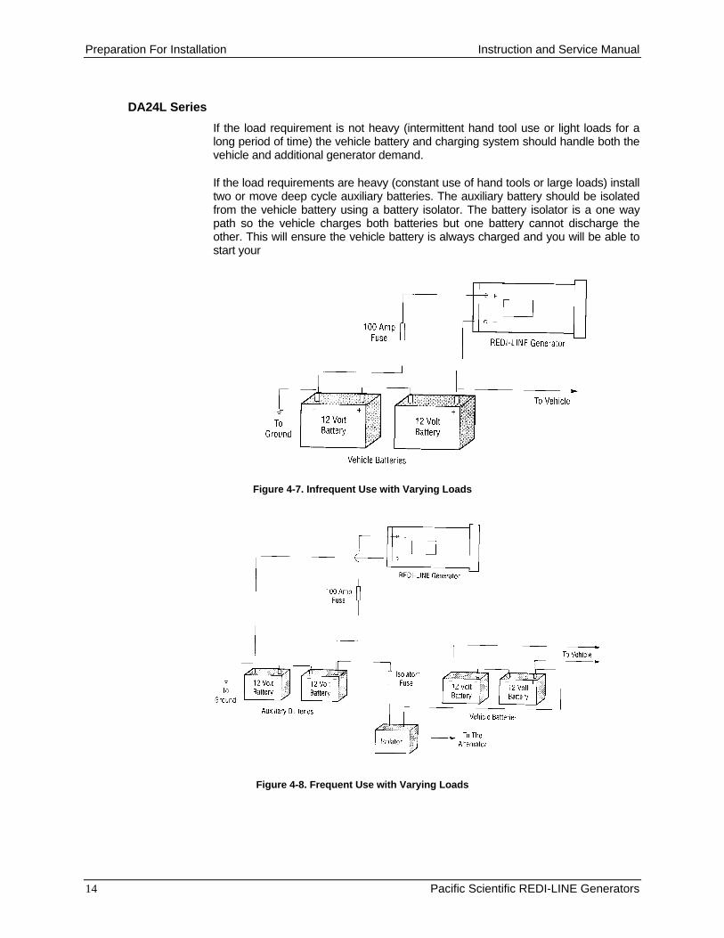
DA24L Series
If the load requirement is not heavy (intermittent hand tool use or light loads for along period of time) the vehicle battery and charging system should handle both thevehicle and additional generator demand.
If the load requirements are heavy (constant use of hand tools or large loads) installtwo or move deep cycle auxiliary batteries. The auxiliary battery should be isolatedfrom the vehicle battery using a battery isolator. The battery isolator is a one waypath so the vehicle charges both batteries but one battery cannot discharge theother. This will ensure the vehicle battery is always charged and you will be able tostart your
Figure 4-7. Infrequent Use with Varying Loads
Figure 4-8. Frequent Use with Varying Loads

Instruction and Service Manual Preparation for Installation
Pacific Scientific REDI-LINE Generators 15
DA36A Series
If the load requirement is not heavy (intermittent hand tool use or light loads for along period of time) the vehicle battery and charging system should handle both thevehicle and additional generator demand.
If the load requirements are heavy (constant use of hand tools or large loads) installtwo or more auxiliary deep cycle batteries. The auxiliary batteries should be isolatedfrom the vehicle battery using a battery isolator. The battery isolator is a one waypath so the vehicle charges both batteries but one battery cannot discharge theother. This will ensure the vehicle battery is always charged and you will be able tostart your vehicle.
Figure 4-9: Infrequent Use with Varying Loads
Figure 4-10. Frequent Use with Varying Loads
Preparation For Installation Instruction and Service Manual
16 Pacific Scientific REDI-LINE Generators
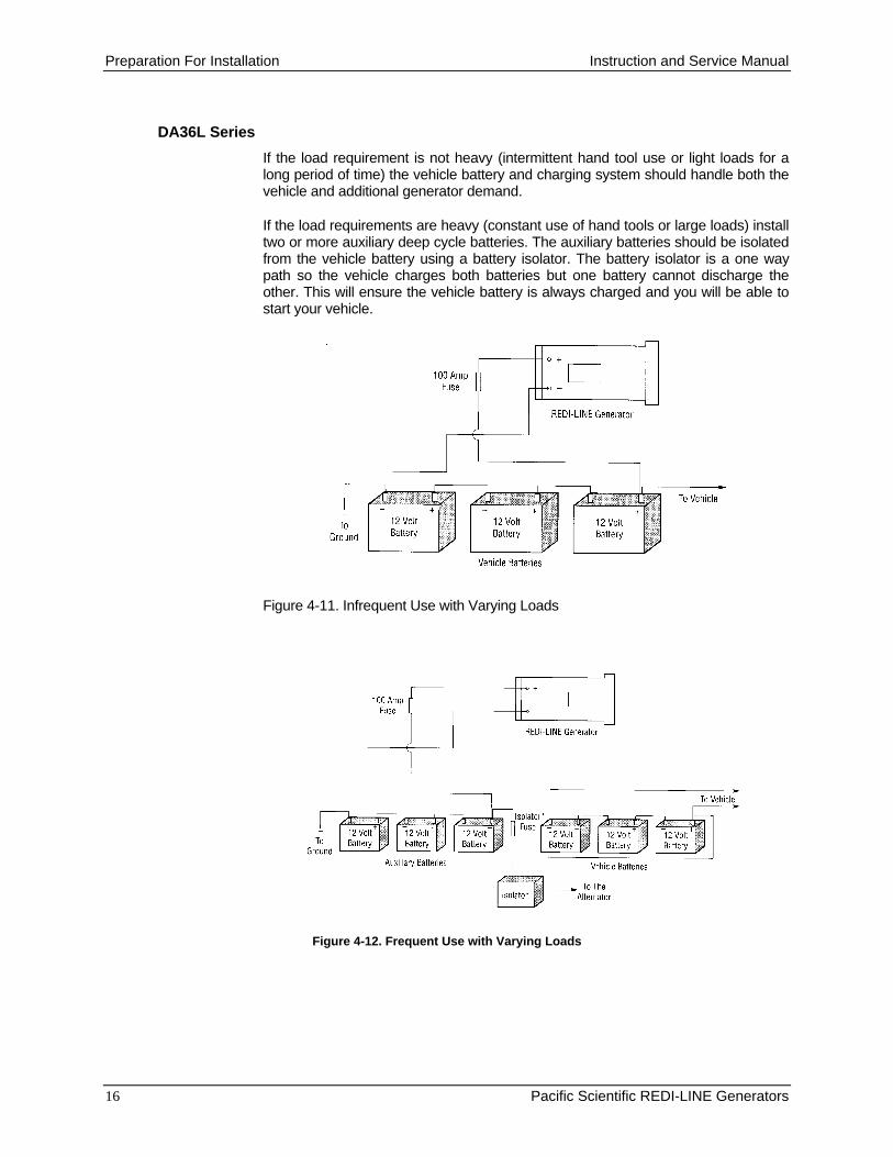
DA36L Series
If the load requirement is not heavy (intermittent hand tool use or light loads for along period of time) the vehicle battery and charging system should handle both thevehicle and additional generator demand.
If the load requirements are heavy (constant use of hand tools or large loads) installtwo or more auxiliary deep cycle batteries. The auxiliary batteries should be isolatedfrom the vehicle battery using a battery isolator. The battery isolator is a one waypath so the vehicle charges both batteries but one battery cannot discharge theother. This will ensure the vehicle battery is always charged and you will be able tostart your vehicle.
Figure 4-11. Infrequent Use with Varying Loads
Figure 4-12. Frequent Use with Varying Loads

Instruction and Service Manual Preparation for Installation
Pacific Scientific REDI-LINE Generators 17
Battery Selection
Standard automotive batteries are designed to supply 300 to 500 amps of currentfor a relatively short period; therefore they are not the best power source for REDI-LINE generators. Deep cycle or marine batteries are designed to deliver lowercurrent levels for a longer time, and are capable of taking deep discharges withoutbattery damage. For this reason, a deep cycle battery is recommended for REDI-LINE operation.
Batteries are rated in cold cranking amps (CCA). In general, the higher the CCA thelonger the battery will operate a generator load. The length of the duty cycledepends on the battery capacity, the size of the load (tool or appliance connected tothe generator), and how frequent the load is applied.
Use the following formula to estimate how long a fully charged deep cycle batterywill keep the REDI-LINE operating continuously before the battery needsrecharging:
Hours =Cold Cranking Amps (CCA)
180 X AC Load Amps
Where:
• Cold Cranking Amps is equal to the sum of all the battery CCAs.
• AC Load Amps is the AC current rating listed on the nameplate of thelargest tool or appliance to be powered by the REDI-LINE generator.
For Example:
• Two batteries with a CCA rating of 675 are used to operate a Generator.
• The tool being operated requires an AC load of 4 amps.
• Continuous run time is:
Hours =675 + 675
180 X 4
= 1.87 Hours
To extend the operating time of the generator further, connect the generator’sbattery system to the vehicle charging system. With the vehicle running, thealternator charges the generator battery bank, thereby providing a longer run time.
If the charging system is not powerful enough, the batteries may still ultimatelybecome discharged after a long operating time. If that is the case, you may need toinstall a larger alternator in your vehicle. Consult your REDI-LINE distributor formore information

Preparation For Installation Instruction and Service Manual
18 Pacific Scientific REDI-LINE Generators
Wiring Considerations
Installation and wiring must conform to all applicable codes, including the NationalElectric Code, state and local, or other codes in effect at the time of installation.
Pacific Scientific recommends that the REDI-LINE Generator always be installedusing proper fuses or circuit breakers. Refer to the appropriate Installation figure(Figures 4-1 through 4-12) for fuse sizes and locations. Place fuses no farther than18" from the battery.
The connection between the supply battery and the REDI- LINE Generator is one ofthe most critical installation steps. Using the wrong supply cable size could damagethe generator. Choose the correct supply cable size from the Table 4-1 below.
Table 4-1. Supply Cable Size Between Battery and REDI-LINE Generator
Cable Length in Feet
Generator up to 3’ 3’ to 8’ 8’ to 10’ 10’ +
DA12A-500AFigure 4-1 and 4-2
No. 6 No. 4 No. 4 No. 4
DA24A-800ADA36A-900A
Figure 4-5, 4-6, 4-9and 4-10
No. 6 No. 6 No. 6 No. 4
DA12L-1600AFigure 4-3
No. 0 No. 0 No. 0 No. 00
DA12L-1600AFigure 4-4
No. 2 No. 2 No. 2 No. 0
DA24L-1600ADA36L-1600A
Figure 4-7, 4-8, 4-11, and 4-12
No. 6 No. 6 No. 6 No. 4

Instruction and Service Manual Installation
Pacific Scientific REDI-LINE Generators 19
5. INSTALLATION
Before Beginning Installation
The REDI-LINE Generator is a quality product, designed to be rugged, reliable andsafe when installed properly. Improper installation can cause damage to the unitand/or result in serious personal injury. Damage caused by incorrectly installing yourREDI-LINE generator is not covered by warranty. Read the entire installationprocedure before you start to install the generator. If you have questions oninstallation or operation of the generator, contact your REDI-LINE distributor forassistance. If you do not have a distributor contact, call Pacific Scientific direct at(815) 226-3100.
To prevent damage to the generator, insure that it is sized properly for theapplication. Excessive AC current draw, above the rating stated on the nameplate,may cause overheating of the generator.
Be sure that all the preparation for installation provisions described in Section 4have been carried out.
CAUTION: Automotive and marine type batteries produce dangerous currentlevels. Protect yourself when working around batteries and associatedelectrical systems. This includes the use of safety goggles.
Mounting
The generator is not position sensitive and may be mounted in whatever orientationbest suits your application.
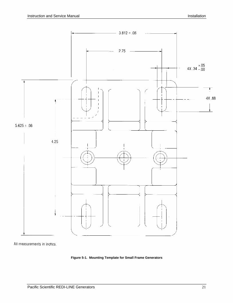
1. Place the unit in the desired position or use the templates in Figures 5-1 or 5-2 to mark the location of the mounting holes.
2. Remove the generator or template. At the marked location, drill 1/4" holes.
3. Attach the generator using four 1/4" flat washers, lock washers, bolts, andnuts through the holes in the base flange. Mounting hardware is not included.
4. Install and secure the batteries in accordance with instructions provided bythe battery manufacturer.

Installation Instruction and Service Manual
20 Pacific Scientific REDI-LINE Generators
Installation Interconnection
Install your REDI-LINE generator according to the interconnection shown in theappropriate installation figure (Figures 4-1 through 4-12). Use the correct cable size(Table 4-1) between the battery and generator. Be sure all electrical connectionsare securely made.
WARNINGIt is important that the polarity (+ and - ) be correctly connected to the generator. Notepolarity indications on the installation figure (Figures 4-1 through 4-12) you are using.
Do not ground the negative (-) REDI-LINE supply terminal to the vehicle chassis. Thenegative REDI-LINE terminal must be connected directly to the supply battery using theproper size supply cable.
NOTE: Cable, connectors, fuses and isolators may be available from yourauthorized REDI-LINE distributor. Many also provide complete installationservices.
NOTE: When attaching power cables to the generator; a spark at theconnection may occur. This is normal and does not mean the generator isdefective.
Instruction and Service Manual Installation
Pacific Scientific REDI-LINE Generators 21
Figure 5-1. Mounting Template for Small Frame Generators

Installation Instruction and Service Manual
22 Pacific Scientific REDI-LINE Generators
Figure 5-2. Mounting Template for Large Frame Generators

Instruction and Service Manual Installation
Pacific Scientific REDI-LINE Generators 23
Installation Checkout
After installation is complete, perform the following checkout to see that the REDI-LINE generator has been properly installed. Where remedial action is indicated,respond as directed. If specific checkout results are not obtained, refer to the fieldtroubleshooting procedure in Section 7 to determine the cause of the problem.
1. Check the REDI-LINE generator to see that it is securely mounted. If it is not,tighten the bolts and nuts securing it to its mounted position.
2. Check the batteries to see that they are securely mounted as directed by themanufacturer. If they are not, complete their installation according to themanufacturer’s directions.
3. Visually inspect the system interconnection to see that it conforms to theinterconnection scheme as shown by the appropriate interconnection drawing(Figures 4-1 through 4-12). Visually check to see that cable routing does notexpose the cables to areas where they could be damaged or cut by sharpedges. If any problems are discovered, correct by reconnecting to conform tothe interconnection drawing, or rerouting to avoid problem areas.
4. Check all connection points to see that they are properly and securely made.Correct any poorly or improperly made connections.
5. Check to see that the REDI-LINE generator is grounded directly to the batteryand not to the vehicle ground. Reconnect if necessary.
6. Apply a load equivalent to a 100-Watt light bulb to the generator. Thegenerator should start. If it does not, see that there is no intervening openswitch between the generator and the load. If there is, close the switch. Thegenerator should start. If it does not, refer to the field troubleshootingprocedure in Section 7.
7. Observe operation of the generator. The generator should run smoothly. If itdoes not, or cycles on and off, add more load to the generator. If this doesnot correct the problem, refer to the field troubleshooting procedure in Section7.
8. Remove the load. The generator should stop within 10 seconds. If it does not,refer to the field troubleshooting procedure in Section 7.
9. Apply the maximum load expected to the generator. The generator shouldstart. If it does not, refer to the field troubleshooting procedure in Section 7
10. Observe operation of the generator. The generator should run smoothly, andat a constant speed. If it does not, refer to the field troubleshooting procedurein Section 7.
11. Remove the load. The generator should stop within 10 seconds. If it does not,refer to the field troubleshooting procedure in Section 7.

Maintenance Instruction and Service Manual
Pacific Scientific REDI-LINE Generators 24
6. MAINTENANCE
Because the REDI-LINE generator contains long life bearings and brushes, it isvirtually maintenance free. We recommend that the few maintenance proceduresgiven below be performed on a periodic basis. Because generator environment andusage varies with each application, we suggest that initial cleaning and inspectionbe performed once a month at first. This period can be extended as experience withthe unit increases.
Cleaning
Wipe down the unit with a shop rag or similar cloth. Be sure that ventilation holesare not plugged. Clean any electrical connections that have become corroded.
Mounting and Electrical Connections
Inspect mounting hardware for tightness and tighten as necessary. Inspect cableand battery connections for tightness, and tighten as necessary. Inspect electricalcables for damage, and replace any that show signs of wear.
Brushes
Inspect brushes periodically to insure uninterrupted service. Brush life expectationsvary based upon the type of tools or appliances you use with the generator. Toavoid damage to the generator, a preventive maintenance inspection interval shouldbe determined for your application. We recommend initially that you inspect thebrushes after 500 hours of use. Brush length after 500 hours of use will help youestablish an appropriate maintenance schedule. Always clean out brush dust wheninspecting or changing brushes.
Damage to the commutators may occur if the brushes are allowed to wear downbelow 0.56-inch minimum length. This minimum length applies to both AC and DCbrushes.
Commutators
When inspecting brushes, check the commutators for wear. If the commutators areworn or pitted, turning and undercutting is recommended. Return your unit to thedistributor or factory for service. . Usually three sets of brushes can be worn outbefore it is necessary to turn the commutators.

Instruction and Service Manual Field Troubleshooting
Pacific Scientific REDI-LINE Generators 25
7. FIELD TROUBLESHOOTING
Field Service
Pacific Scientific recommends that field troubleshooting be performed whenever aproblem is encountered with the REDI-LINE generator, to correct or eliminateproblems caused by faulty installation or load changes, and thereby avoidunnecessary returns.
The following pages contain troubleshooting procedures that should be followed ifthere is a problem in the field. The procedures are oriented toward the installationitself, and are intended to assist in correcting any problems that are a result of aninstallation problem. If the problem cannot be resolved using these procedures, theRedi-Line generator should be returned to the distributor for additional testing andpossible repair.
Most field problems can be traced to installation problems; following theseprocedures closely can eliminate unnecessary returns and keep the Redi-Linegenerator in service.
For your convenience we have included a Field Troubleshooting Checklist Formwhich you should copy and fill out as you perform field troubleshooting. If youshould find it necessary to return the unit for repair, include the form with thegenerator. This will reduce the bench time required by your dealer to diagnose aproblem, and thereby reduce your repair costs.
Use of Flow Charts
Locate your specific symptom or symptoms in the troubleshooting flow chart inFigure 7-1. Each symptom will advise you to return the unit for repair, or refer you toan additional flow chart, which will provide a series of inspections, checks, oractions which will either enable you to return the unit to service, or advise you toreturn the unit for repair.
Field inspection and checkout often consists of a review of installation procedures,materials, and techniques. The areas to be reviewed are specifically identified bythe flow chart. Specific checkout procedures not associated with installation arefound in the subsection titled “Troubleshooting Checkout Procedures” following thetroubleshooting flow charts
Conditional Branches
Where there are conditional branches (diamonds labeled either “Okay” or “Or”),follow the most appropriate path. The conditions for the “Okay” diamonds, shownadjacent to the arrows leaving the diamond, refer to the inspection procedureimmediately preceding the diamond, that is, if the arrow is labeled “yes”, thecondition inspected was found to be satisfactory.
Additional Troubleshooting and Repair
Section 8, Bench Troubleshooting, provides bench troubleshooting procedures, foruse by repair personnel at the distributor’s facility or at the factory. If you have the

Field Troubleshooting Instruction and Service Manual
26 Pacific Scientific REDI-LINE Generators
appropriate equipment and skills, some of the tests and repairs suggested can beperformed in the field. However, before repairs are attempted, you should checkwith your distributor to make sure that such repairs will not void your warranty.
Should You Need to Return the Unit
Before returning any products for repair, authorization must first be received fromyour dealer. Dealer requirements may vary, so contact your dealer for instructionsbefore returning a unit to him.

Instruction and Service Manual Field Troubleshooting
Pacific Scientific REDI-LINE Generators 27
Field Troubleshooting Checklist Form
We have performed the following troubleshooting checks: And the results were:
1.
2.
3.
4.
5.
6.
7.
8.
9.
Customer Name:________________________________________________________________________
Street Address:__________________________________________________________________________
City:_______________________________________________State:___________________Zip:_________
By:____________________________________________
Position:________________________________________
Phone:_________________________________________
Fax:___________________________________________
e-mail:_________________________________________

Field Troubleshooting Instruction and Service Manual
28 Pacific Scientific REDI-LINE Generators
Troubleshooting Flow Charts
GeneratorIs Noisy
Return forRepair
GeneratorIturning too fast
or too slow
See Figure 7-2This Section
Output voltageor frequency too high or
too low
See Figure 7-3This Section
TSFSTART
Generator doesnot start
automatically
See Figure 7-6This Section
Generator doesnot start when
connectedto battery
See Figure 7-4This Section
Generator will notstart motor on
equipmentplugged into it
See Figure 7-5This Section
Generator Startsautomatically but
will not startequipment
plugged into it.
See Figure 7-5This Section
Generator startswhen load isturned on, butstops after afew seconds.
See Figure 7-7This Section
Generator Cycleson and off every
few seconds
See Figure 7-8This Section
Batterydischargestoo quickly
See Figure 7-9This Section
See Figure 7-10This Section
Generator runsall the time
LocateSymptoms
Figure 7-1. Identifying Symptoms

Instruction and Service Manual Field Troubleshooting
Pacific Scientific REDI-LINE Generators 29
Generatorturning too fast
or too slow
Check speedCorrect speed is
3600 RPM atfull load
OkayYes
No
Return to Service
Check cable size frombattery to generator.See Cable Sizing,
Section 4,Preparation for
Installation.
YesNo
OkayInstall correctly
sized cablesReturn toService
Return forRepair
TSFSPEED
Figure 7-2: Generator Running at an Incorrect Speed

Field Troubleshooting Instruction and Service Manual
30 Pacific Scientific REDI-LINE Generators
Using wrongmeter
Output voltageor frequency too high or
too low
No
Recheck withcorrect meter *.
Yes
okay
* Use a True RMS Voltmeter Fluke Models 87, 8060, or 8062 are recommended.
Return forRepair
Check cable size frombattery to generator.See Cable Sizing,
Section 4,Preparation for
Installation.
YesNo
okayInstall correctly
sized cablesReturn toService
Return forRepair
Return toService
Or
Small FramveVersion
LargeFrame Version
Check to see that both setsof DC input terminals are
connected to batteries. See InstallationInterconnection,
Section 5,Installation
YesNo
okayConnect DC InputCables Correctly
Return toService
TSFAVFHL
Figure 7-3: Generator Output Voltage or Frequency Incorrect

Instruction and Service Manual Field Troubleshooting
Pacific Scientific REDI-LINE Generators 31
Generator doesnot start when
connectedto battery
No Load
Check with 100watt light bulb
Okay
YesIncrease load
on generator.Return
to service
No
Return forRepair
TSFACON
Figure 7-4. Generator Does not Start When Connected to Battery

Field Troubleshooting Instruction and Service Manual
32 Pacific Scientific REDI-LINE Generators
Generator will notstart motor on
equipmentplugged into it
OrFaulty
Equipment
Check withIndependent
Power Source
Repair orReplace
Equipment
Return toService
See Figure 7-6This Section
Okay
Okay
Starting LoadToo High
Check StartingLoad
Requirements.See Note
ReduceStarting LoadRequirements
See Figure 7-6This Section
Return toService
NOTE:The Redi-Line Generator can provide 1.5timesits rated capacity for starting motors and loads.
TSFALOAD
Yes
Yes
No
No
Figure 7-5: Generator Runs but does not Start Equipment

Instruction and Service Manual Field Troubleshooting
Pacific Scientific REDI-LINE Generators 33
Generator doesnot start
automatically
IncorrectLoad
Check with 100watt light bulb
Okay
Yes
No
Increase load
on generator.
Returnto service
Incorrectinstallation
Returnfor Repair
Check to see that both setsof DC input terminals are
connected to batteries. See InstallationInterconnection,
Section 4,Installation
Yes
No
okay
Connect DC InputCables Correctly
Return toService
Check to seethat load groundis not connected
to the vehiclebody.
Okay
Returnto service
Connect loadground directly
to battery
Yes
No
Or
Large FrameVersion
OlderVersion*
Neither
OrDefective or Tripped
Circuit Breaker
Reset or ReplaceCircuit Breaker
Return toService
OkayYes
Model Serial Number Break
* Older versions haveserial numbers at or
below those shown below.
TSFPERF
No
DA12A 80294DA12L 81221DA24A 79632DA24L 79203DA36A 79632DA36L
Figure 7-6. Generator Does Not Start Automatically

Field Troubleshooting Instruction and Service Manual
34 Pacific Scientific REDI-LINE Generators
Generator startswhen load is
turned on, butstops after afew seconds.
Okay
Yes
No
Load too high,Circuit
Breaker Trips
Reduce LoadInstall Larger
Generator
Reset CircuitBreaker and
Restart
Return toService
Or
Return toService
OrCheck with 100watt light bulb
Increase load
on generator
Returnto service
Okay
Yes
NoSee Figure 7-5This Section
TSFALOD2
Figure 7-7. Generator Starts With Load, But Stops After A Few Seconds

Instruction and Service Manual Field Troubleshooting
Pacific Scientific REDI-LINE Generators 35
Generator Cycleson and off every
few seconds
Check with 100watt light bulb
Increase load
on generator.
Return to service
Okay
Yes
NoReturn for
Repair
Load is toolight
TSFACYCL
Figure 7-8. Generator Cycles On And Off Every Few Seconds

Field Troubleshooting Instruction and Service Manual
36 Pacific Scientific REDI-LINE Generators
Batterydischargestoo quickly
Determine run timecapability. See Battery
Selection, Section 4,Preparation for
Installation
Install additionalbatteriesOkay
No
Yes
Check to see thatdeep cycle batteries
are being used
Check batterycondition
OkayReplace withnew batteries
No
Yes
Upgrade vehiclecharging system
OkayReplace batteries
with deepcycle type
No
YesReturn toService
TSFAQDIS
Figure 7-9. Battery Discharges Too Quickly

Instruction and Service Manual Field Troubleshooting
Pacific Scientific REDI-LINE Generators 37
Generator runsall the time
InstallationProblem
Check forContinuous
Load. See Note
RemoveContinuous
Load
Return toServiceTSFARUNS
Note: Power strips with ON indicator lamps, equipment with POWERCONNECTED indicator lamps, or similar devices can place enoughload on the generator to cause it to run, even though the intended loadhas been removed.
Figure 7-10. Generator Runs All The Time
Field Troubleshooting Instruction and Service Manual
38 Pacific Scientific REDI-LINE Generators
Other Troubleshooting Checks
Checking Generator Speed
Users familiar with Redi-Line operation may detect a change in sound if thegenerator is running off-speed. Such an occurrence is generally the result of a bador seized bearing and will be accompanied by unusual noise.
Because the rotating components of the Redi-Line generator are totally enclosed, itis difficult to check speed, although it may be done if a suitable strobe unit isavailable. Instead, we suggest you check frequency, which is an indirect, but closelyrelated, indicator of generator speed. If the frequency is within the proper range, itcan be assumed that the generator is functioning properly.
If the generator is producing an unusual noise, but the frequency is within the properrange, monitor the unit closely, and check frequency frequently. If the frequencydegrades, return the unit for service.
Checking Voltage or Frequency
Use a true RMS voltmeter to check voltage or frequency. Many voltmeters will notgive accurate readings, and Pacific Scientific recommends using a Fluke Model, 87,Model 8060, Model 8062, or equivalent.
Connect the voltmeter leads to the power output points on the generator to take areading.
Checking Load
Generator load can be checked using a simple 100-watt light bulb in a keylessfixture mounted on a utility box. Equip the utility box with a short power cord andplug. Follow good electrical practices when constructing the device.
CAUTION: The REDI-LINE generator produces enough current to injure or kill ahuman. Use extreme care when checking the load carrying capabilities ofthe generator.
To check load, simply plug the device into the power receptacle in the generator.The 100-watt light bulb will apply enough load to the unit to function properly.

Instruction and Service Manual Bench Troubleshooting
Pacific Scientific REDI-LINE Generators 39
8. BENCH TROUBLESHOOTING
Units that have been returned for repair are usually accompanied by informationidentifying the problems encountered with the equipment. The troubleshooting flowcharts contained in this section are continuations of the field troubleshooting flowcharts provided in Section 7, Field Troubleshooting, and they therefore reflect thefield complaint initiating the return for repair. These flow charts detail an orderlyprocedure for checking out a faulty unit and isolating the specific problems involved.
Use of Flow Charts
Using the specific field complaints to locate the appropriate troubleshooting flowchart from Figures 8-1 through 8-5. The selected flow chart will provide a series ofinspections, checks, or actions that will enable you to isolate the problem and repairit so the unit can be returned to service.
Checkout procedures are found in the subsection titled “Troubleshooting CheckoutProcedures” following the troubleshooting flow charts. Repair procedures are foundin Section 9, Repair Procedures.
Conditional Branches
Where there are conditional branches (diamonds labeled either “Okay” or “Or”),follow the most appropriate path. The conditions for the “Okay” diamonds, shownadjacent to the arrows leaving the diamond, refer to the inspection procedureimmediately preceding the diamond, that is, if the arrow is labeled “yes”, thecondition inspected was found to be satisfactory.
Assembly and Disassembly
The procedures given in this section pertain to troubleshooting. Individual steps maydirect you to disassemble and assemble a portion of the unit but they will give nodetails. Be sure to follow individual disassembly and assembly procedures given inSection 9, Repair Procedures, when performing these steps.
Bench Troubleshooting Instruction and Service Manual
40 Pacific Scientific REDI-LINE Generators
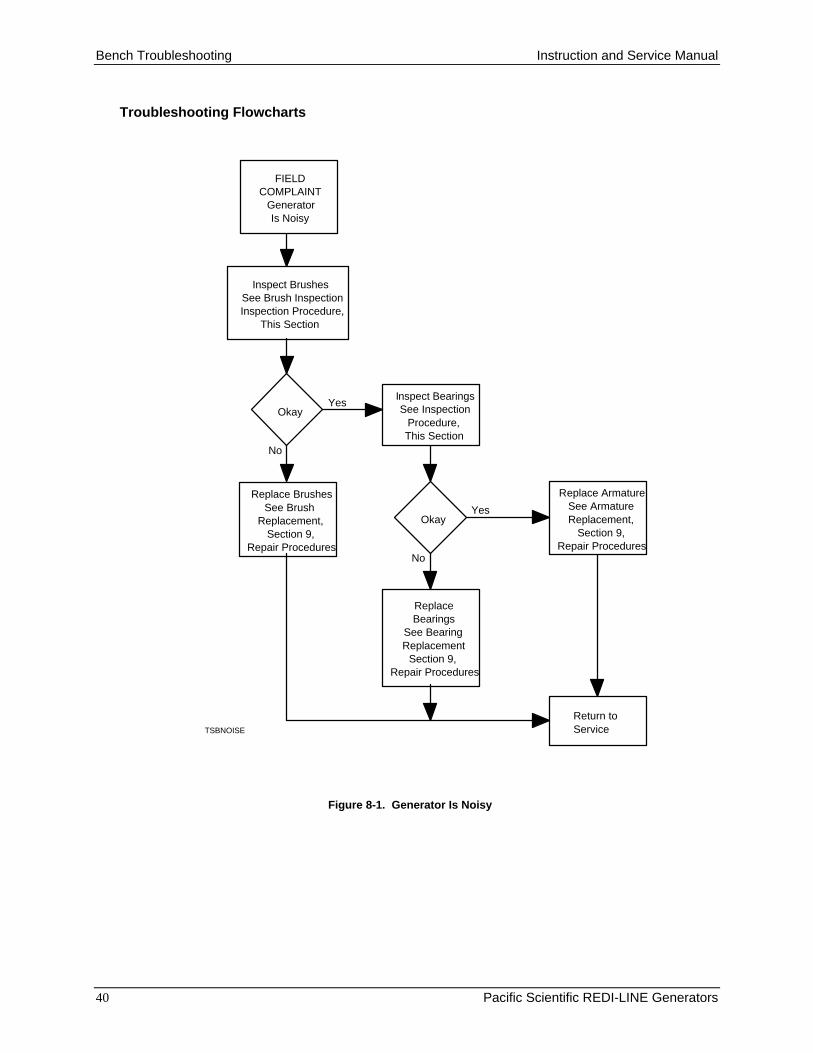
Troubleshooting Flowcharts
FIELDCOMPLAINT
GeneratorIs Noisy
Replace ArmatureSee ArmatureReplacement,
Section 9,Repair Procedures
ReplaceBearings
See BearingReplacement
Section 9,Repair Procedures
Return toServiceTSBNOISE
Okay
Okay
Inspect BearingsSee Inspection
Procedure,This Section
Inspect BrushesSee Brush InspectionInspection Procedure,
This Section
Replace BrushesSee Brush
Replacement,Section 9,
Repair Procedures
Yes
No
Yes
No
Figure 8-1. Generator Is Noisy

Instruction and Service Manual Bench Troubleshooting
Pacific Scientific REDI-LINE Generators 41
FIELDCOMPLAINTS
Generator turningtoo slow...Voltage or
Frequency too low
Yes
Test ArmatureSee InspectionProcedure, this
section
No
okay
Replace ShellSee Disassemblyand Assembly,
Section 9,Repair Procedures
TSBSPEED
Generator turningtoo fast...Voltage or
Frequency toohigh
Return toService
Inspect BearingsSee Inspection
Procedure,This Section
ReplaceBearings
See BearingReplacement
Section 9,Repair Procedures
OkayYes
No
Replace ArmatureSee ArmatureReplacement,
Section 9,Repair Procedures
Figure 8-2. Generator Speed, Voltage, or Frequency Too High or Too Low

Bench Troubleshooting Instruction and Service Manual
42 Pacific Scientific REDI-LINE Generators
TSBANOST
Inspect DC BrushesSee Brush
Inspection Procedure,This Section
Inspect AC BrushesSee Brush
Inspection Procedure,This Section
Inspect DiodeSee Diode
Inspection Procedure,This Section
Inspect Circuit BreakerSee Circuit Breaker
Inspection Procedure,This Section
Inspect Solenoid(s)See Solenoid
Inspection Procedure,This Section
Okay
Yes
No
Okay
Yes
No
Okay
Yes
No
Okay
Yes
No
Okay
Yes
No
Replace ArmatureSee ArmatureReplacement,
Section 9,Repair Procedures
Replace DiodeSee Diode
Replacement,Section 9,
Repair Procedures
Replace Circuit BreakerSee Circuit Breaker
Replacement,Section 9,
Repair Procedures
Replace AC BrushesSee AC BrushReplacement,
Section 9,Repair Procedures
Replace DC BrushesSee DC BrushReplacement,
Section 9,Repair Procedures
Replace Solenoid(s)See SolenoidReplacement,
Section 9,Repair Procedures
Return toService
FIELD COMPLAINTS
Generator doesnot start when
connected to battery
Generator doesnot start
automatically
Or
NewerVersion*
OlderVersion*
Replace PC Board.See PC BoardReplacement,
Section 9.Repair Procedures
OkayYes
No
Model Serial Number Break
* Older versions haveserial numbers at or
below those shown below.
DA12A 80294
DA12L 81221DA24A 79632DA24L 79203DA36A 79632DA36L
Figure 8-3. Generator Does Not Start When Connected to the Batteryor Does Not Start Automatically

Instruction and Service Manual Bench Troubleshooting
Pacific Scientific REDI-LINE Generators 43
Field Complaint
Generator Cycleson and offeveryfew seconds
Or
OlderVersion*
NewerVersion
Does NotOccur
Replace PC Board.See PC BoardReplacement,
Section 9Repair ProceduresTSBACYCL
Return toService
Model Serial Number Break
* Older versions haveserial numbers at or
below those shown below.
DA12A 80294DA12L 81221DA24A 79632DA24L 79203DA36A 79632DA36L
Figure 8-4. Generator Cycles On and Off Every Few Seconds
Bench Troubleshooting Instruction and Service Manual
44 Pacific Scientific REDI-LINE Generators
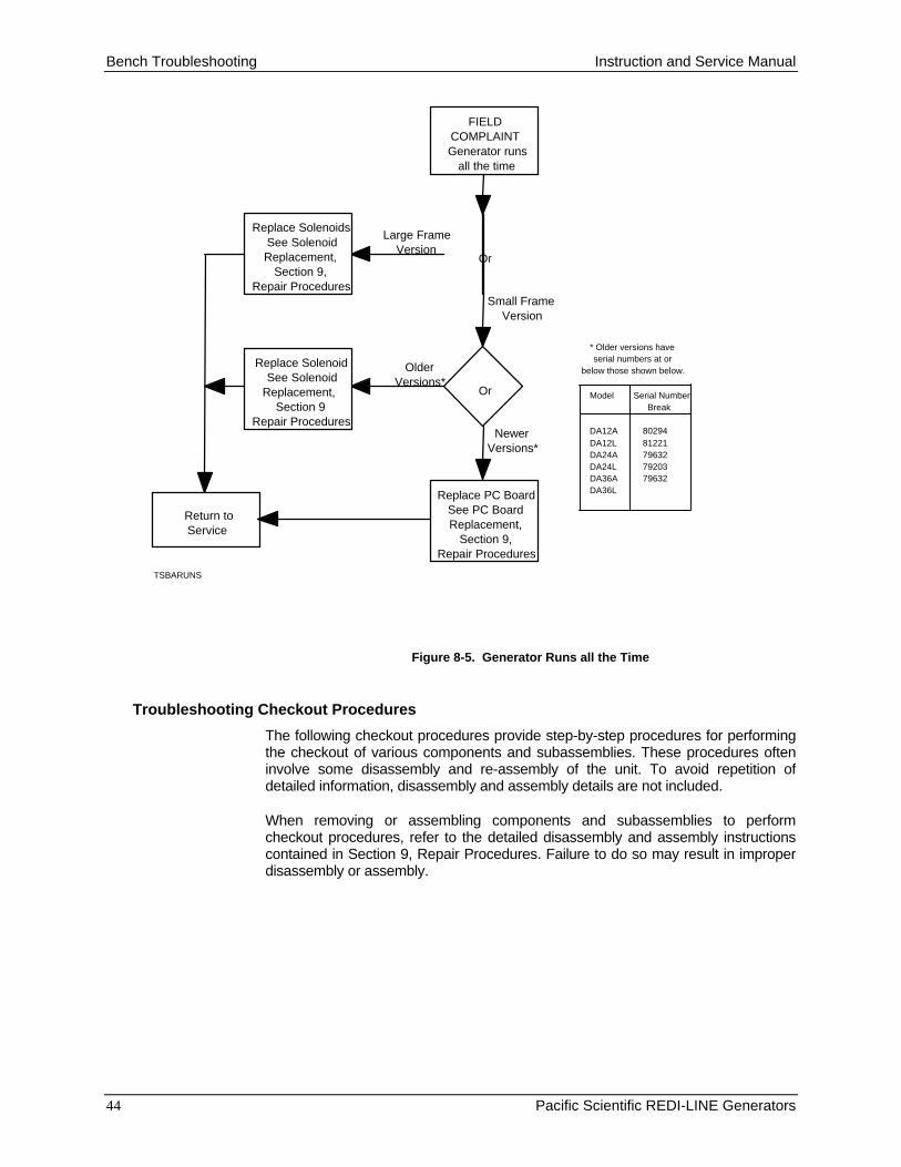
FIELDCOMPLAINTGenerator runs
all the time
Or
Large FrameVersion
Small FrameVersion
Or
OlderVersions*
NewerVersions*
Replace SolenoidsSee SolenoidReplacement,
Section 9,Repair Procedures
Return toService
Replace PC BoardSee PC BoardReplacement,
Section 9,Repair Procedures
Replace SolenoidSee Solenoid
Replacement,Section 9
Repair Procedures
TSBARUNS
Model Serial Number Break
* Older versions haveserial numbers at or
below those shown below.
DA12A 80294DA12L 81221DA24A 79632DA24L 79203DA36A 79632DA36L
Figure 8-5. Generator Runs all the Time
Troubleshooting Checkout Procedures
The following checkout procedures provide step-by-step procedures for performingthe checkout of various components and subassemblies. These procedures ofteninvolve some disassembly and re-assembly of the unit. To avoid repetition ofdetailed information, disassembly and assembly details are not included.
When removing or assembling components and subassemblies to performcheckout procedures, refer to the detailed disassembly and assembly instructionscontained in Section 9, Repair Procedures. Failure to do so may result in improperdisassembly or assembly.

Instruction and Service Manual Bench Troubleshooting
Pacific Scientific REDI-LINE Generators 45
Procedure No. 1: DC Brush Inspection
Procedure:
1. Remove any electrical connections to the generator.
2. Remove the electrical assembly cover.
3. Disconnect the lead wires to the components inside the cover.
4. If servicing a small frame unit, remove the rear end bell from the housing,
OR…..If servicing a large frame unit, remove the DC brush covers.
5. Check the brushes for free travel within their holders.
6. Remove the brushes and springs. Make note of the position and orientationof each brush removed; if reused, individual brushes must be returned to thesame holders, in the same orientation as removed.
7. Visually inspect the springs for distortion.
8. Visually inspect the brushes for damage.
9. Inspect the overall length of the brushes.
10. Reassemble the entire unit.
11. Reconnect the battery and test the unit with a load (100-watt light bulb).
Desired Results:
1. The brushes should move freely within their holders with no binding whenthey are depressed, and return to their original positions when released.
2. A small amount of spring distortion is acceptable.
3. Brush faces should be smooth, and the entire brush should be free fromdefects.
4. Brushes should not be shorter than 0.56 inches.
5. Generator should start and run steadily.
Disposition:
1. If any brush binding is found, remove the brushes and clean them and theirholders.
2. In small frame units, If major distortion of the spring is discovered, replacethe entire rear end bell, OR…..In large frame units, replace the spring.
3. Burnishing of the brush faces is acceptable, but if pitting or damage isdiscovered, replace both brushes in the pair. Inspect the armaturecommutator for damage.
4. If either brush is too short, replace both brushes in the pair.

Bench Troubleshooting Instruction and Service Manual
46 Pacific Scientific REDI-LINE Generators
Procedure No. 2: AC Brush Inspection
Procedure:
1. Remove any electrical connections to the generator.
2. Remove the electrical assembly cover.
3. Disconnect the lead wires to the components inside the cover.
4. Carefully remove the brush holder assemblies.
5. Check the brushes for free travel within their holders.
6. Remove the brushes and springs. Make note of the position and orientationof each brush removed; if reused, individual brushes must be returned to thesame holders, in the same orientation as removed.
7. Visually inspect the springs for distortion.
8. Visually inspect the brushes for damage.
9. Inspect the overall length of the brushes.
10. Reassemble the entire unit.
Desired Results:
1. The brushes should move freely within their holders with no binding whenthey are depressed, and return to their original positions when released.
2. A small amount of spring distortion is acceptable.
3. Brush faces should be smooth, and the entire brush should be free fromdefects.
4. Brushes should not be shorter than .056 inches.
5. Generator should start and run steadily.
Disposition:
1. If any brush binding is found, remove the brushes and clean them and theirholders.
2. If major distortion of the spring is discovered, replace the spring.
3. Burnishing of the brush faces is acceptable, but if pitting or damage isdiscovered, replace both brushes in the pair. Inspect the armaturecommutator for damage.
4. If either brush is too short, replace both brushes in the pair.

Instruction and Service Manual Bench Troubleshooting
Pacific Scientific REDI-LINE Generators 47
Procedure No. 3: Bearing Inspection
Procedure:
1. Remove any electrical connections to the generator.
2. Remove the end cap covering the cooling fan.
3. Manually spin the armature by turning the fan in both directions.
Desired Results:
The armature should turn freely in both directions. Do not mistake magneticresistance for bearing binding.
Disposition:If any roughness or binding is found, replace the bearings.
Procedure No. 4: Commutator Inspection
Procedure:
1. Remove any electrical connections to the generator.
2. Remove one AC brush assembly from each commutator.
3. Remove one brush access cover from each DC commutator.
4. Visually inspect each commutator for scoring, pitting, or other signs ofdamage.
Desired Results:
There should be no evidence of damage. Burnishing of the commutator isacceptable.
Disposition:If any damage is found, replace the armature.
NOTE: A damaged commutator may be resurfaced and undercut if facilities andskills are available to do so. However, it is recommended that any armature withcommutator damage be replaced.
Bench Troubleshooting Instruction and Service Manual
48 Pacific Scientific REDI-LINE Generators
Procedure No. 5: Armature Test
Procedure:
1. Disassemble the generator.
2. Measure the resistance between adjacent AC slip rings.
3. Measure the resistance of the DC windings by testing adjacent bars all theway around the commutator.
Desired Results:
1. Resistance between adjacent AC slip rings should fall between 0.5 and 1.5ohms.
2. Resistance between adjacent bars of the DC windings should be consistentlysimilar.
Disposition:
1. If there is no resistance or excessive (infinite) resistance between adjacentslip rings, replace the armature.
2. If there is no resistance or excessive (infinite) resistance between adjacentbars of the DC windings, replace the armature.
3. If there is measurable but inconsistent resistance between adjacent bars ofthe DC windings, remove any dirt or foreign metal pieces which may havecreated a bridge between the bars. Recheck the resistance. If it is stillinconsistent, replace the armature.

Instruction and Service Manual Bench Troubleshooting
Pacific Scientific REDI-LINE Generators 49
Procedure No. 6: Solenoid Test
NOTE: This test does to apply to a DA12A-500A. This generator does not have a solenoid.
Procedure:
1. Disconnect the battery from the generator.
2. Remove the electrical assembly cover from the generator but do notdisconnect any electrical wires.
3. Remove the PC board from the starting circuit by bypassing it with a jumperas shown in Figure 8-6 or 8-7.
4. Reconnect the battery to the generator and apply a load (100-watt light bulb).
Figure 8-6. Jumper Connection - Small Frame Unit
Figure 8-7. Jumper Connection - Large Frame Unit
Desired Results:There should be an audible click from the solenoid.
Disposition:
1. If there is no click, replace the solenoid.
2. If there is a click, the solenoid is functioning, but DC power is not beingapplied to the armature.
Bench Troubleshooting Instruction and Service Manual
50 Pacific Scientific REDI-LINE Generators
Procedure No. 7: Circuit Breaker Test
Procedure:
1. Remove any electrical connections to the generator.
2. Remove the electrical assembly cover from the generator but do notdisconnect any electrical wires.
3. Disconnect the black wires from the circuit breaker inside the electricalassembly cover. Make note of the connection locations so re-assembly canbe performed correctly.
4. Measure the resistance between the circuit breaker terminals.
Desired Results:
Resistance between the circuit breaker terminals should be less than 1 ohm.
Disposition:
1. If resistance is greater than 1 ohm, replace the circuit breaker.
2. If resistance is less than 1 ohm, the circuit breaker is good.

Instruction and Service Manual Bench Troubleshooting
Pacific Scientific REDI-LINE Generators 51
Procedure No. 8: Diode Test
NOTE: This test does not apply to Redi-Line Generator models DA12L-1600A and DA12A-500A.
Procedure:
1. Remove any electrical connections to the generator.
2. If checking a small frame generator, separate but do not disconnect theelectrical assembly cover from the generator…
OR…..
If servicing a large frame unit, remove the cover over the electrical assembly.Do not disconnect any internal lead wires.
3. Disconnect the orange and white lead wires from the PC board. Note the wiringplacement so the lead wires can be reconnected properly to the terminalsduring re-assembly.
4. Set the ohmmeter to either the R X 1 or the R X 10 resistance range.
5. Measure resistance between the orange lead and ground, and between thewhite lead and ground, as follows:
A. Red probe to ground; black probe to orange lead.
B. Black probe to ground; red probe to orange lead.
C. Red probe to ground; black probe to white lead.
D. Black probe to ground; red probe to white lead.
Desired Results:For each of the resistance readings, the value should fall between zero and infinity,but not at zero or infinity.
Disposition:If either the A or B reading is zero (a shorted diode) or infinity (an open diode)replace the diode assembly connected to the orange lead.
If either the C or D reading is zero (a shorted diode) or infinity (an open diode)replace the diode assembly connected to the white lead.

Repair Procedures Instruction and Service Manual
52 Pacific Scientific REDI-LINE Generators
9. REPAIR PROCEDURES
General
Repair of Redi-Line generators is confined to replacement of defective parts. Thefollowing procedures, therefore, consist of disassembly and assembly proceduresonly. Many of the components are located on or accessible from the exterior of theunit, and can be removed independently of one another, in any order preferred.Thus, many components can be serviced without disturbing other components.Overall, the order presented is the best when disassembling the unit completely.
When disconnecting and removing electrical components, note the connectionpoints, sequence of parts on studs, and wire routing carefully. Misconnection ofelectrical components can result in damage to the unit after assembly. Becausethere is scant room for wiring, the routing of wires is important. If major assembly isundertaken, or if the unit will be re-assembled later, make a sketch of connectionsand wire routing as the unit is disassembled.
Numbers in parentheses following component names refer to the appropriateexploded view in Section 10, Parts Lists.
Disassembly and re-assembly instructions do not include a step-by-step procedureto account for every component. Disassembly and re-assembly of manycomponents, especially those which will seldom require replacement, is self-evidentand instructions should not be necessary. Keep such components together withtheir attaching parts, so re-assembly after some delay will not become difficult.
Recommended Tools and Equipment
In addition to ordinary hand tools such as pliers, screwdrivers, and wrenches, theservice technician will find it highly beneficial to have the following tools readilyavailable:
1. Small jumper wires with alligator clips at each end. (For jumping solenoids.)
2. Retaining-ring pliers.
3. A True RMS Voltmeter (Fluke Models 87, 8060, or are recommended.)
4. The service technician will find it highly beneficial to have the following equipmentreadily available:
1. Two 12-volt deep-cycle batteries, at least 85 amp-hr each. To protect againstaccidental shorts, it is recommended that a 200-amp fuse be installed as closeas possible to the positive terminal of each battery.
2. Battery cable, at least #4 gauge, preferably #2 gauge. The exact length of cableneeded depends upon the set-up of the test bench. Terminals used on thebattery cable should be copper.

Instruction and Service Manual Repair Procedures
Pacific Scientific REDI-LINE Generators 53
3. 100W light bulb assembly (for testing generator performance). This deviceconsists of a 100-watt light bulb in a keyless fixture mounted on a utility box.Equip the utility box with a short power cord and plug. Follow good electricalpractices when constructing the device.
Disassembly of Small Frame Units
NOTE: Steps 2, 3, and 4 can be done independently of one another.
1. Remove any electrical connections to the generator.
2. Remove DC Brush Assembly (1) from unit. Brushes are not retained in theassembly, so withdraw the assembly carefully. Note wire connections for laterre-assembly.
3. Remove solenoid cover (3) by removing acorn nuts (9). Disconnect theelectrical connections carefully, noting their relationships. If necessary, removesolenoid (14) or printed circuit board (24) from solenoid cover.
4. Remove fan shroud (10) by removing screws (11).If necessary remove fanimpeller (12) from armature shaft by removing C ring (13)
NOTE: Steps 5 through 8 must be done in the order presented.
5. Remove nuts (37) from tie rods (36).
6. Remove rear end bell (30). See the paragraph below titled Brush Replacementfor further disassembly instructions.
7. Remove front end bell (31) and armature (39) as a unit. Withdraw thecomponents from the shell briskly to reduce the amount of magnetic attractionto the armature.
8. If armature (39) is to be replaced, separate bearing (35) from front end bell (30)end bell with a rubber hammer (the bearing is bonded to the end bell).

Repair Procedures Instruction and Service Manual
54 Pacific Scientific REDI-LINE Generators
Re-assembly of Small Frame Units
NOTE: Steps 1 through 4 must be done in the order presented.
1. Assemble front end bell (31) and armature (39). Install bearing (35) onarmature and retain with C ring (40) before joining end bell to armature.
2. Insert tie rods (36) through end bell (31). Route the white lead wire over theupper tie rod after it is inserted through the end bell.
3. Carefully Install armature (39) and end bell (31) assembly into shell assembly(43).
CAUTION: The magnets will attract the armature as it is inserted. Do not let thearmature commutator or bearing to strike a magnet.
4. Install rear end bell (30). Retain with nuts (37). See the paragraph below titledBrush Replacement for end bell assembly instructions.
NOTE: Steps 5 through 8 can be done independently of one another. Steps 1through 4 must be complete beforehand.
5. Install the electrical components inside solenoid cover (3). Make sure wirerouting and electrical connections are properly made.
6. Install solenoid cover (3) on shell assembly (43) and secure with nuts (29).
7. Install fan (12), if necessary and fan cover (10).
8. Install AC brush assembly (1). Prepare the brush assembly for installation byfeeding a small solid copper over the face of the brush and out the small hole inassembly cover. This retains the brush in the holder during installation. Removethe retaining wire after the assembly is secured.

Instruction and Service Manual Repair Procedures
Pacific Scientific REDI-LINE Generators 55
Disassembly of Large Frame Units
NOTE: Steps 2, through 6 can be done independently of one another.
1. Remove any electrical connections to the generator.
2. Remove solenoid cover (1). Disconnect the electrical connections carefully,noting their relationships. If necessary, remove printed circuit board (7) fromsolenoid cover. Note wire routing and connections for later re-assembly.
3. If necessary, remove solenoid(s) (9 or 15) from top of housing. Note wireconnections for later re-assembly. (Step 2 must be completed first.)
4. Remove AC brush assemblies (12 or 16) from unit. Brushes are not retained inthe assembly, so withdraw the assemblies carefully. Note wire connections forlater re-assembly.
5. Remove DC brush access covers (14 or 18). Remove DC brush springs andbrushes. See the paragraph below titled Brush Replacement for removalinstructions.
6. Remove fan shroud (21 or 25) by removing screws (22 or 26). If necessaryremove fan impeller (23 or 27) from armature shaft by removing C ring (24 or28).
NOTE: Steps 7 through 13 must be done in the order presented.
7. Disconnect terminals protruding through terminal insulator(s) (16 or 20). Notewire connections for later re-assembly.
8. If necessary, remove the terminal nut (39 or 43) from the negative battery post.Note wire connections for later re-assembly.
9. Remove nuts (28 or 32) from tie rods (27 or 31)).
10. Remove rear end bell (26 or 30). The negative battery post is removed with therear end bell. See the paragraph below titled Brush Replacement for furtherdisassembly instructions.
11. Remove nuts (29 or 33) from tie rods (27 or 31)
12. Remove front end bell (25 or 29) and armature (39, 43, 44, or 48) as a unit.Withdraw the components from the shell briskly to reduce the amount ofmagnetic attraction to the armature.
13. If armature (39, 43, 44, or 48) is to be replaced, separate bearing (36, 40, 41 or45) from front end bell (25 or 29) end bell with a rubber hammer (the bearing isbonded to the end bell).

Repair Procedures Instruction and Service Manual
56 Pacific Scientific REDI-LINE Generators
Re-assembly of Large Frame Units
NOTE: Steps 1 through 7 must be done in the order presented.
1. Assemble front end bell (25 or 29) and armature (39, 43, 44, or 48). Installbearing (36, 40, 41, or 45)) on armature and retain with C ring before joiningend bell to armature.
2. Insert tie rods (27 or 31) through end bell (25 or 29).
3. Carefully Install armature (39, 43, 44, or 48) and end bell (25 or 29) assemblyinto shell assembly (43).
CAUTION: The magnets will attract the armature as it is inserted. Do not let thearmature commutator or bearing to strike a magnet.
4. Install nuts (29 or 33) on tie rods (27 or 31). Do not tighten.
5. Install rear end bell (26 or 30). See the paragraph below titled BrushReplacement for end bell assembly instructions.
6. If necessary, install the terminal nut (39 or 43) on the negative battery post onrear end bell (26 or 30). Be sure wire connection components are installed inthe reverse order from which they were removed.
7. Re-install terminals through terminal insulator(s) (16 or 20). Be sure wireconnection components are installed in the reverse order from which they wereremoved.
NOTE: Steps 8 through 12 can be done independently of one another. Steps 1through 7 must be complete beforehand.
8. If necessary install fan impeller (23 or 27) on armature shaft and retain with Cring (24 or 28). Install fan shroud (21 or 25) and retain with screws (22 or 26).
9. Install DC brush springs and brushes. See the paragraph below titled BrushReplacement for installation instructions. Install DC brush access covers (14 or18).
10. Install AC brush assembly (1). Prepare the brush assembly for installation byfeeding a small solid copper over the face of the brush and out the small hole inassembly cover. This retains the brush in the holder during installation. Removethe retaining wire after the assembly is secured.
11. If necessary, install solenoid(s) (9 or 15) on top of housing. Make sure wirerouting and electrical connections are properly made.
12. Install the electrical components inside solenoid cover (1). Make sure wirerouting and electrical connections are properly made. Install solenoid cover onhousing and secure with screws (2).

Instruction and Service Manual Repair Procedures
Pacific Scientific REDI-LINE Generators 57
DC Brush Removal and Replacement
Refer to Figure 9-1 .
Removal
1. Move brush shunts out of the way from the spring.
2. Note the brush ramp position and spring location before removing brushes.Brushes must be installed in the same orientations.
3. Push the spring handle until it clicks. This indicates that the spring isdisengaged from the brush holder.
4. Carefully remove the spring (Do not pull on the coiled spring.) Disconnect thebrush shunt from the brush holder and remove brush.
Re-assembly
1. Insert the brushes in the brush holder. Position the ramp in exactly the sameas it was when removed.
2. Install the spring assembly so that the bottom of the brush ramp is closest tothe spring assembly.
3. Press on the spring assembly to ensure the hook on the end of the springengages with the brush holder.
4. Connect the brush shunts.
Figure 9-1. Brush Removal and Installation
Repair Procedures Instruction and Service Manual
58 Pacific Scientific REDI-LINE Generators
Checkout after Repair
Checking Voltage or Frequency
Use a true RMS voltmeter to check voltage or frequency. Many voltmeters will notgive accurate readings, and Pacific Scientific recommends using a Fluke Model, 87,Model 8060, Model 8062, or equivalent.
Connect the voltmeter leads to the power output points on the generator to take areading.
Checking Load
Generator load can be checked using a simple 100-watt light bulb.
CAUTION: The REDI-LINE generator produces enough current to injure or kill ahuman. Use extreme care when checking the load carrying capabilities ofthe generator.
To check load, simply plug the device into the power receptacle in the generator.The 100-watt light bulb will apply enough load to the unit to function properly.

Instruction and Service Manual Parts Lists
Pacific Scientific REDI-LINE Generators 59
10. PARTS LISTS
Models Covered
The following parts lists cover small frame generator models DA12A, DA24A, andDA36A; and large frame generator models DA12L and DA24L. Several versions ofeach of these models exist; and the parts lists cover these earlier versions as wellas the latest current versions. Where practical, earlier and later versions arecombined on a single exploded view, and separate part number columns identifythe parts for each version.
Parts List Conventions
Each parts list consists of four or more columns. Where additional columns arepresent, there are duplicate part number columns, each column pertaining to aspecific Redi-Line model.
The item column contains the callout found on the illustration on the facing page.Items in the illustration are numbered generally in disassembly order, were the unitto be disassembled completely. Attaching parts (screws, nuts, washers, etc.), andsimilar parts, are usually listed after the parts they attach.
The part number column provides the Pacific Scientific part number; this partnumber is to be used when ordering the item from Pacific Scientific or your localdealer.
The description column identifies assemblies and assembly parts through the useof dots preceding the item description. A single dot indicates that the item is a partof the unit described by the parts list. Two dots indicate that the item is a part of thesingle-dot item or assembly immediately preceding it.

Parts Lists Instruction and Service Manual
60 Pacific Scientific REDI-LINE Generators
34
33
1716
24
26
25
27
20
23
22
21
14
6
4
9
8
7
5
4241
3837
28
29
39
40
1819
31
32
35
44
45
36
46
43
10
11 13
12
1
2
15
3
30
Figure 10-1: Small Frame Generators

Instruction and Service Manual Parts Lists
Pacific Scientific REDI-LINE Generators 61
Table 10-1: Parts List - Small Frame Generators
Part Number
Item DA12A DA12A-500 DA12A-500A Description Qty
Ref FGD1201 FGD1297 FGD1252 Generator Assembly 1
1 YP63444 YP63444 YP63444 . AC Brush Assembly 2
2 YK11230 YK11230 YK11230 . Screw, Slotted, Pan Hd, 10-32 X 3/8 4
3 NO LONGERAVAILABLE
NO LONGERAVAILABLE
YC63231 . Solenoid Cover 1
4 YP04403 YP04403 YP04403 . Electrical Receptacle 1
5 YN00046 YN00046 YN00046 . Decal 1
6 YP05506 YP05506 YP05506 . Circuit Breaker, 12 Volt 1
6 YP05508 YP05508 YP05508 . Circuit Breaker, 24 Volt, 36 Volt 1
7 NO PARTNUMBER
AVAILABLE
NO PARTNUMBER
AVAILABLE
NO PARTNUMBER
AVAILABLE
. . Nut, Lock 1
8 NO PARTNUMBER
AVAILABLE
NO PARTNUMBER
AVAILABLE
NO PARTNUMBER
AVAILABLE
. . Washer 1
9 YK10069 YK10069 YK10069 . Nut, Acorn, ¼-20 2
10 YC63229 YC63229 YC63229 . Fan Shroud 1
11 YK11230 YK11230 YK11230 . Screw,, Hex Hd, 10-32 X 3/8 1
12 NO LONGERAVAILABLE
YP01630 YP01630 . Fan Impeller 1
13 NOT USED VM31079 VM31079 , C-Ring 1
NI NO PARTNUMBER
AVAILABLE
NO PARTNUMBER
AVAILABLE
NOT USED . Solenoid Assembly 1
14 NO LONGERAVAILABLE
NO LONGERAVAILABLE
NOT USED . . Solenoid 1
15 NO LONGERAVAILABLE
NO LONGERAVAILABLE
NOT USED . . Nut 1
16 NO LONGERAVAILABLE
NO LONGERAVAILABLE
NOT USED . . Nut 1
17 NO LONGERAVAILABLE
NO LONGERAVAILABLE
NOT USED . . Washer 1
18 NOT USED NO LONGERAVAILABLE
NOT USED . . Diode 1
19 NOT USED NO LONGERAVAILABLE
NOT USED . . Screw, Hex Head 1
20 NO LONGERAVAILABLE
NOT USED NOT USED . Printed Circuit Board 1
21 NO LONGERAVAILABLE
NOT USED NOT USED . Nut 1
22 NO LONGERAVAILABLE
NOT USED NOT USED . Nut 1
23 NO LONGERAVAILABLE
NOT USED NOT USED . Washer 1
continued…..

Parts Lists Instruction and Service Manual
62 Pacific Scientific REDI-LINE Generators
34
33
1716
24
26
25
27
20
23
22
21
14
6
4
9
8
7
5
4241
3837
28
29
39
40
1819
31
32
35
44
45
36
46
43
10
11 13
12
1
2
15
3
30
Figure 10-1: Small Frame Generators, continued

Instruction and Service Manual Parts Lists
Pacific Scientific REDI-LINE Generators 63
Table 10-1: Parts List - Small Frame Generators, continued
Part Number
Item DA12A DA12A-500 DA12A-500A Description Qty
Ref FGD1201 FGD1297 FGD1252 Generator Assembly 1
24 NOT USED NOT USED YP05816 . Printed Circuit Board and Bracket 1
25 NOT USED NOT USED YK10027 . Nut, ¼-20 1
26 NOT USED NOT USED YK10384 . Washer, ¼-20 1
27 NOT USED NOT USED YK10027 . Nut, ¼-20 1
28 YP05251 YP05251 YP05251 . Tab, Printed Circuit Board, copper 1
29 YK10027 YK10027 YK10027 . Nut, ¼-20 1
30 NO LONGERAVAILABLE
YR33072 YR33072 . Rear End Bell 1
NI NO PART NO PART NO PART . Front End Bell Assembly 1
31 NO LONGERAVAILABLE
YF20274 YF20274 . . Front End Bell 1
32 NO LONGERAVAILABLE
NOT USED NOT USED . . Plate, Diode 1
33 YK11077 NOT USED NOT USED . . Screw, Slotted, Pan Head, 6-32 2
34 YK10090 NOT USED NOT USED . . Washer, No. 6 2
35 HB623SL HB623SL HB623SL . Bearing, 6203, double sealed 1
36 YJ10106 YJ10106 YJ10106 . Tie Rod 2
37 YK10027 YK10027 YK10027 . Nut, ¼-20 2
38 YK10384 YK10384 YK10384 . Washer, Flat 2
NI NO LONGERAVAILABLE
YAA3053 YAA3053 . Armature Assembly, 12 Volt (Armature Assembly w/ bearings)
1
NO LONGERAVAILABLE
YAA3309 YAA3309 . Armature Assembly, 24 Volt (Armature Assembly w/ bearings)
NO LONGERAVAILABLE
YAA5575 YAA5575 . Armature Assembly, 36 Volt (Armature Assembly w/ bearings)
39 NO LONGERAVAILABLE
YA13053 YA13053 . . Armature, 12 Volt 1
39 NO LONGERAVAILABLE
YA13309 YA13309 . . Armature, 24 Volt 1
39 NO LONGERAVAILABLE
YA15575 YA15575 . . Armature, 36 Volt 1
40 NOT USED YK11722 YK11722 . . C-Ring 1
41 HB623SL HB623SL HB623SL . . Bearing, 6203, double sealed 1
42 YP03151 YP03151 YP03151 . Washer, Wavy Spring 1
43 NO LONGERAVAILABLE
YH83042 YH83042 . Shell Assembly, 12 Volt 1
43 NO LONGERAVAILABLE
YH83053 YH83053 . Shell Assembly, 24 Volt 1
43 NO LONGERAVAILABLE
YH83053 YH83053 . Shell Assembly, 36 Volt 1
44 YP80007 YP80007 YP80007 . Foot Mount 1
45 YK11231 YK11231 YK11231 . Screw, Hex Head, ¼-20 X 9/16 3
46 YP00987 YP00987 YP00987 . Plug 2

Parts Lists Instruction and Service Manual
64 Pacific Scientific REDI-LINE Generators
14
13
97
23
12
6
12 3
9
7
2
6
4
5
1
10
7
8 11
7
10
8
Figure 10-2. End Bell for Earlier Small Frame Generators

Instruction and Service Manual Parts Lists
Pacific Scientific REDI-LINE Generators 65
Table 10-2: Parts List - End Bell for Earlier Small Frame Generators
Item Part No. Description Qty
Ref NO LONGER AVAILABLE End Bell Assembly 1
1 NO LONGER AVAILABLE . End Bell 1
NI NO LONGER AVAILABLE Brush Holder Assembly 2
2 NO LONGER AVAILABLE . . Brush Holder Plate 2
3 YP00351 . . Brush 2
4 YP02213 . Insulator , Brush 2
5 YP02211 . Brush Holder Insulator 2
6 YP02224 . Diode Plate Spacer 2
7 YP02220 . Diode Plate Insulator 4
8 YK10021 . Bolt, Slotted Head, 8-32 X 1-1/2 2
9 YK10314 . Nut, Std. Hex, 8-32 2
10 YP02218 . Insulator 2
11 YP02103 . Power Terminal 2
12 YK10027 . Nut, Std. Hex, ¼-20 2
13 NO LONGER AVAILABLE . Diode, 25 Amp X 800 Volt, Black (negative) 1
14 NO LONGER AVAILABLE . Diode, 25 Amp X 800 Volt, Red (positive) 1

Parts Lists Instruction and Service Manual
66 Pacific Scientific REDI-LINE Generators
1
2
3
4
64
3
2
7
5
85
7
Figure 10-3. End Bell for Current Small Frame Generators

Instruction and Service Manual Parts Lists
Pacific Scientific REDI-LINE Generators 67
Table 10-3: Parts List - End Bell for Current Small Frame Generators
Item Part No. Description Qty
Ref YR33072 End Bell Assembly 1
1 YR20193 . End Bell 1
2 YP00351 . Brush 2
3 YP00872 . Brush Spring 2
4 YP02246 . Insulator, Brush 2
5 YP02103 . Power Terminal 2
6 YK10027 . Nut, Std. Hex, ¼-20 2
7 YK10384 . Washer 2
8 YK10027 . Nut, Std. Hex, ¼-20 2

Parts Lists Instruction and Service Manual
68 Pacific Scientific REDI-LINE Generators
46
47
32
30
26
25
40
41
19
1816
1719
18
3148
4528
27
3537
3633
29
34
3938
18
1922 21
20
24
23
18
1915
12
1314
9
7
8
4
1110 15
17
16
23
2421
22
20
49
43
42
44
3
562
1
Figure 10-4: 12 Volt Large Frame Generator, Earliest Version

Instruction and Service Manual Parts Lists
Pacific Scientific REDI-LINE Generators 69
Table 10-4: Parts List - 12-Volt Large Frame Generator, Earliest Version
Item Part No. Description Qty
DA12L-1600 Generator Assembly 1
1 NO LONGER AVAILABLE . Solenoid Cover 1
2 YK11230 . Screw, Slotted, Pan Hd, 10-32 X 3/8 2
3 YP04403 . Electrical Receptacle 2
4 YP05509 . Reset Assembly 1
5 NO PART NUMBERAVAILABLE
. . Nut, Lock 1
6 NO PART NUMBERAVAILABLE
. . Washer 1
7 NO LONGER AVAILABLE . Printed Circuit Board 1
8 YK11230 . Screw, Slotted, Pan Hd 2
9 NO LONGER AVAILABLE . Circuit Board Bracket 1
10 YP05251 . Terminal End 1
11 YK11230 . Screw, Slotted, Pan Head, 10-32 X 3/8 2
12 YP05251 . Terminal End 1
13 YP05251 . Terminal End 1
14 YK11230 . Screw, Slotted, Pan Hd, 10-32 X 3/8 2
15 NO LONGER AVAILABLE . Solenoid 2
16 YP63445 . Brush Assembly 2
17 YK11230 . Screw, Slotted, Pan Hd, 10-32 X 3/8 4
18 YP00315 . Access Cover 4
19 YK11230 . Screw, Slotted, Pan Hd, 10-32 X 3/8 8
20 YN00096 . Terminal Insulator 1
21 YK11656 . Washer, Lock 2
22 YK11658 . Washer, Flat 2
23 YK11656 . Nut, 5/16 2
24 YK10960 . Nut, 5/16 2
25 YP80105 . End Cover (Shroud) 1
26 YK11230 . Screw, Slotted, Pan Hd 3
27 YP01581 . Fan Impeller 1
28 YK11134 . C-Ring 1
29 YR70150 . Bell Assembly, Front End, (opposite fan shroud end) 1Continued…..

Parts Lists Instruction and Service Manual
70 Pacific Scientific REDI-LINE Generators
46
47
32
30
26
25
40
41
19
1816
1719
18
3148
4528
27
3537
3633
29
34
3938
18
1922 21
20
24
23
18
19
15
12
1314
9
7
8
4
1110 15
17
16
23
2421
22
20
49
43
42
44
3
562
1
Figure 10-4: 12-Volt Large Frame Generator, Earliest Version, continued

Instruction and Service Manual Parts Lists
Pacific Scientific REDI-LINE Generators 71
Table 10-4: Parts List - 12-Volt Large Frame Generator, Earliest Version, Continued
Item Part No. Description Qty
Ref DA12L-1600 Generator Assembly 1
30 NO LONGER AVAILABLE . Bell Assembly, Rear End (fan shroud end) 1
31 YJ10358 . Tie Rod 4
32 YK11322 . Nut, Acorn, 10-32 4
33 YK10960 . Nut, Lock, 10-32 2
34 YP03151 . Washer, Wavy Spring 1
35 YL35532 . Terminal, Positive, with lead wire 1
36 YP02237 . Insulator 1
37 YK11424 . Washer 1
38 YP02237 . Insulator 1
39 YK11424 . Washer 1
40 YK11424 . Insulator 1
41 YK11424 . Washer 1
42 YL35532 . Terminal, Positive, with lead wire 1
43 YP02237 . Insulator 1
44 YK11424 . Washer 1
45 HB623SL . Bearing, 6203, double sealed 1
46 HB623SL , Bearing, 6203, double sealed 1
47 YK10199 . C-Ring 1
48 NO LONGER AVAILABLE . Armature 1
49 NO LONGER AVAILABLE . Housing 1

Parts Lists Instruction and Service Manual
72 Pacific Scientific REDI-LINE Generators
46
47
32
30
26
25
40
41
19
1816
1719
18
3148
4528
27
3537
3633
29
34
3938
18
1922 21
20
24
23
18
19
15
12
1314
9
7
8
4
1110
1517
16
23
2421
22
20
49
43
42
44
3
562
1
Figure 10-5: 12-Volt Large Frame Generator, Interim Version

Instruction and Service Manual Parts Lists
Pacific Scientific REDI-LINE Generators 73
Table 10-5: Parts List - 12-Volt Large Frame Generator, Interim Version
Item Part No. Description Qty
Ref DA12L-1600-1 Generator Assembly 1
1 NO LONGER AVAILABLE . Solenoid Cover 1
2 YK11230 . Screw, Slotted, Pan Hd, 10-32 X 3/8 4
3 YP04403 . Electrical Receptacle 2
4 YP05509 . Reset Assembly 1
5 NO PART NUMBER . . Nut, Lock 1
6 NO PART NUMBER . . Washer 1
7 NO LONGER AVAILABLE . Printed Circuit Board 1
8 NO LONGER AVAILABLE . Screw, Slotted, Pan Hd, 10-32 X 3/8 2
9 NO LONGER AVAILABLE . Circuit Board Bracket 1
10 YP05251 , Terminal End 1
11 YK11230 . Screw, Slotted, Pan Head, 10-32 X 3/8 2
12 YP05251 . Terminal End 1
13 YP05251 . Terminal End 1
14 YK11230 . Screw, Slotted, Pan Hd, 10-32 X 3/8 2
15 NO LONGER AVAILABLE . Solenoid 2
16 YP63445 . Brush Assembly 2
17 YK11230 . Screw, Slotted, Pan Hd, 10-32 X 3/8 4
18 YP00315 . Access Cover 4
19 YK11230 . Screw, Slotted, Pan Hd, 10-32 X 3/8 8
20 YN00096 . Terminal Insulator 1
21 YK11656 . Washer, Lock 2
22 YK11658 . Washer, Flat 2
23 YK11656 . Nut, 5/16 2
24 YK10915 . Nut, 5/16 2
25 YP80105 . End Cover, (Shroud) 1
26 YK11230 . Screw, Slotted, Pan Hd 3
27 YP01581 . Fan Impeller 1
28 YK11134 . C-Ring 1
29 YR70150 . Bell Assembly, Front End, (Opposite Fan Shroud) 1
30 YR70215 . Bell Assembly, Rear End, (Fan Shroud End) 1Continued…..

Parts Lists Instruction and Service Manual
74 Pacific Scientific REDI-LINE Generators
46
47
32
30
26
25
40
41
19
1816
1719
18
3148
4528
27
3537
3633
29
34
3938
18
1922 21
20
24
23
18
19
15
12
1314
9
7
8
4
1110
1517
16
23
2421
22
20
49
43
42
44
3
562
1
Figure 10-5: 12-Volt Large Frame Generator, Interim Version, continued

Instruction and Service Manual Parts Lists
Pacific Scientific REDI-LINE Generators 75
Table 10-5: Parts List - 12-Volt Large Frame Generator, Interim Version, Continued
Item Part No. Description Qty
Ref DA12L-1600-1 Generator Assembly 1
31 YJ11240 . Tie Rod 4
32 YK11322 . Nut, Acorn, 10-32 4
33 YK10960 . Nut, Lock, 10-32 4
34 YP03151 . Washer, Wavy Spring, 1
35 YL35532 . Terminal, Positive, with lead wire 1
36 YP02237 . Insulator 2
37 YK11424 . Washer 2
38 YP02237 . Insulator 1
39 YK11424 . Washer 1
40 YP02237 . Insulator 1
41 YK11424 . Washer 1
42 YL35532 . Terminal, Positive, with lead wire 1
43 YP02237 . Insulator 1
44 YK11424 . Washer 1
45 HB623SL . Bearing, 6203, double sealed 1
46 HB623SL . Bearing, 6203, double sealed 1
47 YK11722 . C-Ring 1
48 YAA5170 . Armature 1
49 YH84277 . Housing 1

Parts Lists Instruction and Service Manual
76 Pacific Scientific REDI-LINE Generators
81 6 5
2
3
4
711
10
913
12
19
201718
9
11
10
19
2017
18
15
14
16
16
39
40
38
45
15
14
36
37 26
28
22
21
42
43
12
1315
14
24
23
2744
41
3133
32
30
29
25
3534
14
15
Figure 10-6: 12-Volt Large Frame Generator, Current Version
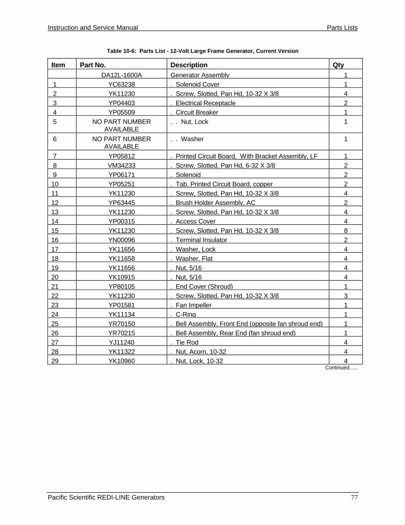
Instruction and Service Manual Parts Lists
Pacific Scientific REDI-LINE Generators 77
Table 10-6: Parts List - 12-Volt Large Frame Generator, Current Version
Item Part No. Description Qty
DA12L-1600A Generator Assembly 1
1 YC63238 . Solenoid Cover 1
2 YK11230 . Screw, Slotted, Pan Hd, 10-32 X 3/8 4
3 YP04403 . Electrical Receptacle 2
4 YP05509 . Circuit Breaker 1
5 NO PART NUMBERAVAILABLE
. . Nut, Lock 1
6 NO PART NUMBERAVAILABLE
. . Washer 1
7 YP05812 . Printed Circuit Board, With Bracket Assembly, LF 1
8 VM34233 . Screw, Slotted, Pan Hd, 6-32 X 3/8 2
9 YP06171 . Solenoid 2
10 YP05251 . Tab, Printed Circuit Board, copper 2
11 YK11230 . Screw, Slotted, Pan Hd, 10-32 X 3/8 4
12 YP63445 . Brush Holder Assembly, AC 2
13 YK11230 . Screw, Slotted, Pan Hd, 10-32 X 3/8 4
14 YP00315 . Access Cover 4
15 YK11230 . Screw, Slotted, Pan Hd, 10-32 X 3/8 8
16 YN00096 . Terminal Insulator 2
17 YK11656 . Washer, Lock 4
18 YK11658 . Washer, Flat 4
19 YK11656 . Nut, 5/16 4
20 YK10915 . Nut, 5/16 4
21 YP80105 . End Cover (Shroud) 1
22 YK11230 . Screw, Slotted, Pan Hd, 10-32 X 3/8 3
23 YP01581 . Fan Impeller 1
24 YK11134 . C-Ring 1
25 YR70150 . Bell Assembly, Front End (opposite fan shroud end) 1
26 YR70215 . Bell Assembly, Rear End (fan shroud end) 1
27 YJ11240 . Tie Rod 4
28 YK11322 . Nut, Acorn, 10-32 4
29 YK10960 . Nut, Lock, 10-32 4Continued…..

Parts Lists Instruction and Service Manual
78 Pacific Scientific REDI-LINE Generators
81 6 5
2
3
4
711
10
913
12
19
201718
9
11
10
19
2017
18
15
14
16
16
39
40
38
45
15
14
36
37 26
28
22
21
42
43
12
1315
14
24
23
2744
41
3133
32
30
29
25
3534
14
15
Figure 10-6: 12-Volt Large Frame Generator, Current Version, continued
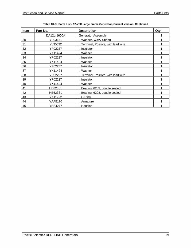
Instruction and Service Manual Parts Lists
Pacific Scientific REDI-LINE Generators 79
Table 10-6: Parts List - 12-Volt Large Frame Generator, Current Version, Continued
Item Part No. Description Qty
DA12L-1600A Generator Assembly 1
30 YP03151 . Washer, Wavy Spring 1
31 YL35532 . Terminal, Positive, with lead wire 1
32 YP02237 . Insulator 1
33 YK11424 . Washer 1
34 YP02237 . Insulator 1
35 YK11424 . Washer 1
36 YP02237 . Insulator 1
37 YK11424 . Washer 1
38 YP02237 . Terminal, Positive, with lead wire 1
39 YP02237 . Insulator 1
40 YK11424 . Washer 1
41 HB623SL . Bearing, 6203, double sealed 1
42 HB623SL . Bearing, 6203, double sealed 1
43 YK11722 . C-Ring 1
44 YAA5170 . Armature 1
45 YH84277 . Housing 1

Parts Lists Instruction and Service Manual
80 Pacific Scientific REDI-LINE Generators
9
16
1719
18
1
2 6
5
3
4
8
711
1014
13
12
15
17
16
23
24212220
38
19
18
39
34
353736
33
29
40
4331
42
41
30
32
26
25
28
27
44
Figure 10-7: 24-Volt Large Frame Generator, Earlier Version

Instruction and Service Manual Parts Lists
Pacific Scientific REDI-LINE Generators 81
Table 10-7: Parts List - 24-Volt Large Frame Generator, Earlier Version
Item Part No. Description Qty
Ref DA24L-1600 Generator Assembly 1
1 NO LONGER AVAILABLE . Solenoid Cover 1
2 YK11230 . Screw, Slotted, Pan Hd, 10-32 X 3/8 4
3 YP04403 . Electrical Receptacle 2
4 YP05509 . Circuit Breaker 1
5 NO PART NUMBERAVAILABLE
. . Nut, Lock 1
6 NO PART NUMBERAVAILABLE
. . Washer 1
7 NO LONGER AVAILABLE . Printed Circuit Board 1
8 NO LONGER AVAILABLE . Screw, Slotted, Pan Hd 2
9 NO LONGER AVAILABLE . Circuit Board Bracket 1
10 YP05251 , Terminal End 1
11 YK11230 . Screw, Slotted, Pan Head 1
12 YP05251 . Terminal End 1
13 YP05251 . Terminal End 1
14 YK11230 . Screw, Slotted, Pan Hd 1
15 NO LONGER AVAILABLE . Solenoid 1
16 YP63445 . Brush Assembly 2
17 YK11230 . Screw, Slotted, Pan Hd, 10-32 X 3/8 4
18 YP00315 . Access Cover 2
19 YK11230 . Screw, Slotted, Pan Hd, 10-32 X 3/8 4
20 YN00096 . Terminal Insulator 1
21 YK11656 . Washer, Lock 2
22 YK11658 . Washer, Flat 2
23 YK11656 . Nut, 5/16 2
24 YK10915 . Nut, 5/16 2
25 YP80105 . End Cover, (Shroud) 1
26 YK11230 . Screw, Slotted, Pan Hd 3
27 YP01581 . Fan Impeller 1
28 YK11134 . C-Ring 1
29 YR70226 . Bell Assembly, Front End (opposite fan shroud end) 1
30 NO LONGER AVAILABLE . Bell Assembly, Rear End (fan shroud end) 1Continued…..

Parts Lists Instruction and Service Manual
82 Pacific Scientific REDI-LINE Generators
9
16
1719
18
1
2 6
5
3
4
8
711
1014
13
12
15
17
16
23
24212220
38
19
18
39
34
353736
33
29
40
4331
42
41
30
32
26
25
28
27
44
Figure 10-7: 24-Volt Large Frame Generator, Earlier Version, continued

Instruction and Service Manual Parts Lists
Pacific Scientific REDI-LINE Generators 83
Table 10-7: Parts List - 24-Volt Large Frame Generator, Earlier Version, continued
Item Part No. Description Qty
Ref DA24L-1600 Generator Assembly 1
31 YK11212 . Tie Rod 2
32 YK11322 . Nut, Acorn, 10-32 2
33 YK10915 . Nut, Lock, 10-32 2
34 YP03151 . Washer, Wavy Spring 1
35 YL35532 . Terminal, Positive, with lead wire 1
36 YP02237 . Insulator 1
37 YK11424 . Washer 1
38 YP02237 . Insulator 1
39 YK11424 . Washer 1
40 HB623SL . Bearing, 6203, double sealed 1
41 HB623SL . Bearing, 6203, double sealed 1
42 YK11722 . C-Ring 1
43 YAA5168 . Armature Assembly 1
44 YH84279 . Housing 1
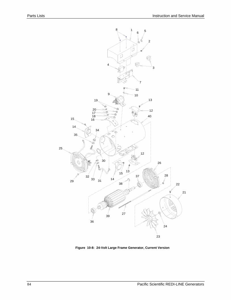
Parts Lists Instruction and Service Manual
84 Pacific Scientific REDI-LINE Generators
8 16
5
2
34
7
11
109
12
1319
201718
1640
34
15
14
35
30
12
25
29
3233 31 14
1513
37
38
2739
36
22
21
24
23
26
28
Figure 10-8: 24-Volt Large Frame Generator, Current Version

Instruction and Service Manual Parts Lists
Pacific Scientific REDI-LINE Generators 85
Table 10-8: Parts List - 24-Volt Large Frame Generator, Current Version
Item Part No. Description Qty
Ref DA24L-1600A Generator Assembly 1
1 YC63238 . Solenoid Cover 1
2 YK11230 . Screw, Slotted, Pan Hd, 10-32 X 3/8 4
3 YP04403 . Electrical Receptacle 2
4 YP05509 . Circuit Breaker 1
5 NO PART NUMBERAVAILABLE
. . Nut, Lock 1
6 NO PART NUMBERAVAILABLE
. . Washer 1
7 YP05612 . Printed Circuit Board, With Bracket Assembly, LF 1
8 VM34233 . Screw, Slotted, Pan Hd 2
9 YP06171 . Solenoid 1
10 YP05251 , Tab, Printed Circuit Board, copper 1
11 YK11230 . Screw, Slotted, Pan Hd, 10-32 X 3/8 2
12 YP63445 . Brush Holder Assembly, AC 2
13 YK11230 . Screw, Slotted, Pan Hd, 10-32 X 3/8 4
14 YP00315 . Access Cover 2
15 YK11230 . Screw, Slotted, Pan Hd, 10-32 X 3/8 4
16 YN00096 . Terminal Insulator 1
17 YK11656 . Washer, Lock 2
18 YK11658 . Washer, flat 2
19 YK11656 . Nut, 5/16 2
20 YK10915 . Nut, 5/16 2
21 YP80105 . End Cover (Shroud) 1
22 YK11230 . Screw, Slotted, Pan Hd, 10-32 X 3/8 3
23 YP01581 . Fan Impeller 1
24 YK11134 . C-Ring 1
25 YR70226 . Bell Assembly, Front End (opposite fan shroud end) 1
26 YR70226 . Bell Assembly, Rear End (fan shroud end) 1
27 YJ11212 . Tie Rod 4
28 YK11322 . Nut, Acorn, 10-32 4
29 YK10960 . Nut, Lock, 10-32 4
30 YP03151 . Washer, Wavy Spring 1Continued…..

Parts Lists Instruction and Service Manual
86 Pacific Scientific REDI-LINE Generators
8 16
5
2
34
7
11
109
12
1319
201718
1640
34
15
14
35
30
12
25
29
3233 31
14
1513
37
38
2739
36
22
21
24
23
26
28
Figure 10-8: 24-Volt Large Frame Generator, Current Version, continued

Instruction and Service Manual Parts Lists
Pacific Scientific REDI-LINE Generators 87
Table 10-8: Parts List - 24-Volt Large Frame Generator, Current Version, Continued
Item Part No. Description Qty
Ref DA24L-1600A Generator Assembly 1
31 YL35532 . Terminal, Positive, with lead wire 1
32 YP02237 . Insulator 1
33 YK11424 . Washer 1
34 YP02237 . Insulator 1
35 YK11424 . Washer 1
36 HB623SL . Bearing, 6203, double sealed 1
37 HB623SL . Bearing, 6203, double sealed 1
38 YK11722 . C-Ring 1
39 YAA5168 . Armature 1
40 YH84279 . Housing 1
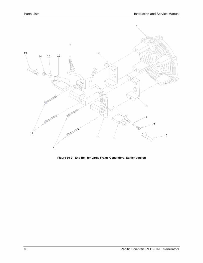
Parts Lists Instruction and Service Manual
88 Pacific Scientific REDI-LINE Generators
6
7
8
52
4
11
1314 15 12
9
10
1
3
Figure 10-9: End Bell for Large Frame Generators, Earlier Version
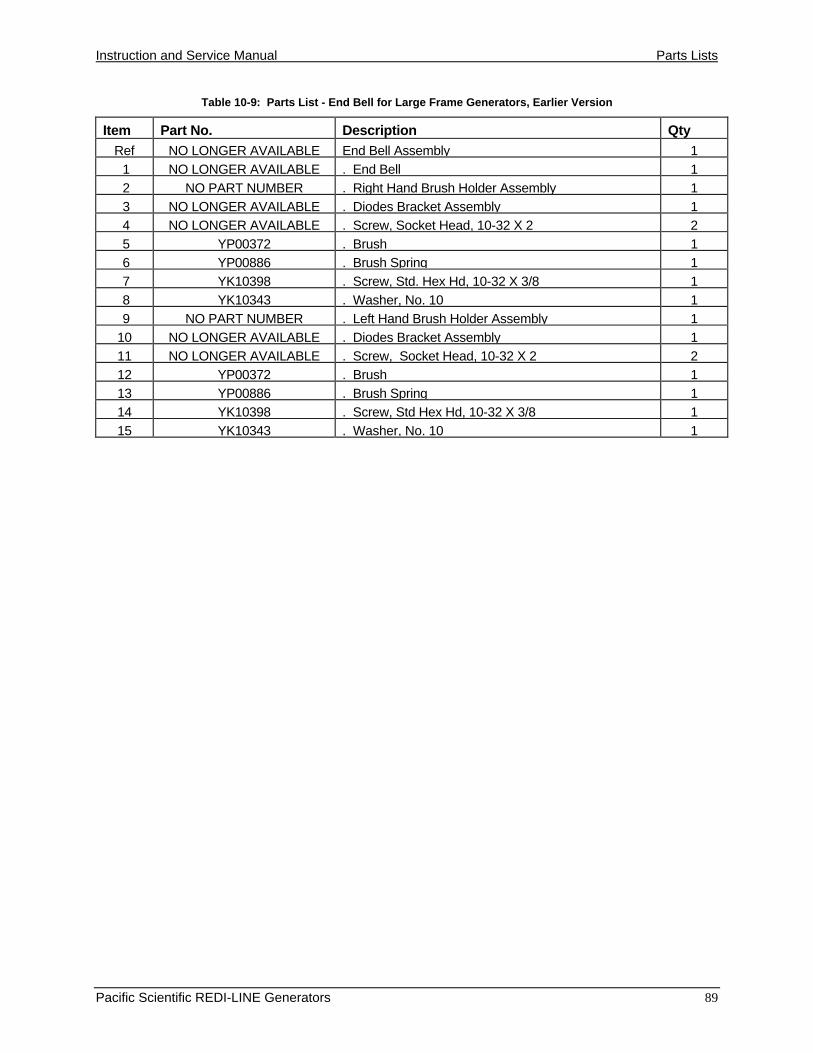
Instruction and Service Manual Parts Lists
Pacific Scientific REDI-LINE Generators 89
Table 10-9: Parts List - End Bell for Large Frame Generators, Earlier Version
Item Part No. Description Qty
Ref NO LONGER AVAILABLE End Bell Assembly 1
1 NO LONGER AVAILABLE . End Bell 1
2 NO PART NUMBER . Right Hand Brush Holder Assembly 1
3 NO LONGER AVAILABLE . Diodes Bracket Assembly 1
4 NO LONGER AVAILABLE . Screw, Socket Head, 10-32 X 2 2
5 YP00372 . Brush 1
6 YP00886 . Brush Spring 1
7 YK10398 . Screw, Std. Hex Hd, 10-32 X 3/8 1
8 YK10343 . Washer, No. 10 1
9 NO PART NUMBER . Left Hand Brush Holder Assembly 1
10 NO LONGER AVAILABLE . Diodes Bracket Assembly 1
11 NO LONGER AVAILABLE . Screw, Socket Head, 10-32 X 2 2
12 YP00372 . Brush 1
13 YP00886 . Brush Spring 1
14 YK10398 . Screw, Std Hex Hd, 10-32 X 3/8 1
15 YK10343 . Washer, No. 10 1

Parts Lists Instruction and Service Manual
90 Pacific Scientific REDI-LINE Generators
5
6
7
4
2
14
3
9
11
12
13
10
8
14
1
Figure 10-10: End Bell for Large Frame Generators, Current Version

Instruction and Service Manual Parts Lists
Pacific Scientific REDI-LINE Generators 91
Table 10-10: Parts List - End Bell for Large Frame Generators, Current Version
Item Part No. Description Qty
Ref YR70215 End Bell Assembly 1
1 YR20226 . End Bell 1
2 NO PART NUMBER . Right Hand Brush Holder Assembly 1
3 YK11738 . Screw, Socket Head, 10-32 X 2 2
4 YP00372 . Brush 1
5 YP00886 . Brush Spring 1
6 YK10398 . Screw, Std. Hex Hd, 10-32 X 3/8 1
7 YK10343 . Washer, No. 10 1
8 NO PART NUMBER . Left Hand Brush Holder Assembly 1
9 YK11738 . Screw, Socket Head, 10-32 X 2 2
10 YP00372 . Brush 1
11 YP00886 . Brush Spring 1
12 YK10398 . Screw, Std Hex Hd, 10-32 X 3/8 1
13 YK10343 . Washer, No. 10 1
14 YP02985 . Standoff 4

Technical Data Instruction and Service Manual
92 Pacific Scientific REDI-LINE Generators
11. TECHNICAL DATA
Performance Curves
Figures 11-1 through 11-5 are performance curves, and should be used only byrepair technicians who can apply it properly to generator performance during thecourse of bench analysis and repair. It is not of use to the generator user.
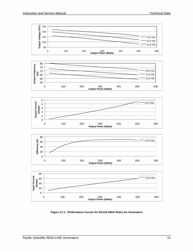
Instruction and Service Manual Technical Data
Pacific Scientific REDI-LINE Generators 93
Figure 11-1: Performance Curves for DA12A-500A Redi-Line Generators
80
100
120
140
160
0 100 200 300 400 500 600Output Power (Watts)
Ou
tpu
t V
olt
age
(VA
C)
13.6 Vdc
12.6 Vdc
11.6 Vdc
55
60
65
70
75
80
0 100 200 300 400 500 600Output Power (Watts)
Ou
tpu
t F
req
uen
cy
(Hz)
13.6 Vdc
12.6 Vdc
11.6 Vdc
0
1
2
3
4
5
0 100 200 300 400 500 600Output Power (Watts)
Ou
tpu
t C
urr
ent
(Am
ps)
12.6 Vdc
0
20
40
60
80
0 100 200 300 400 500 600Output Power (Watts)
Eff
icie
ncy
(%
)
12.6 Vdc
0
20
40
60
80
0 100 200 300 400 500 600Output Power (Watts)
Inp
ut
Cu
rren
t (A
mp
s)
12.6 Vdc

Technical Data Instruction and Service Manual
94 Pacific Scientific REDI-LINE Generators
Figure 11-2: Performance Curves for DA12L-1600A Redi-Line Generators
80
100
120
140
160
0 200 400 600 800 1000 1200 1400 1600 1800 2000Output Power (Watts)
Ou
tpu
t V
olt
age
(VA
C)
14.6 Vdc13.6 Vdc12.6 Vdc11.6 Vdc
55
60
65
70
75
80
0 200 400 600 800 1000 1200 1400 1600 1800 2000Output Power (Watts)
Ou
tpu
t F
req
uen
cy
(Hz)
14.6 Vdc
13.6 Vdc
12.6 Vdc
11.6 Vdc
0
5
10
15
20
0 200 400 600 800 1000 1200 1400 1600 1800 2000Output Power (Watts)
Ou
tpu
t C
urr
ent
(Am
ps)
13.6 Vdc
0
20
40
60
80
0 200 400 600 800 1000 1200 1400 1600 1800 2000Output Power (Watts)
Eff
icie
ncy
(%
) 13.6 Vdc
0
50
100
150
200
250
0 200 400 600 800 1000 1200 1400 1600 1800 2000Output Power (Watts)
Inp
ut
Cu
rren
t (A
mp
s)
12.6 Vdc
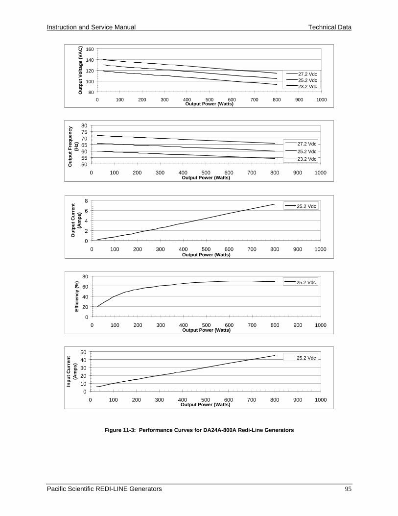
Instruction and Service Manual Technical Data
Pacific Scientific REDI-LINE Generators 95
Figure 11-3: Performance Curves for DA24A-800A Redi-Line Generators
80
100
120
140
160
0 100 200 300 400 500 600 700 800 900 1000Output Power (Watts)
Ou
tpu
t V
olt
age
(VA
C)
27.2 Vdc25.2 Vdc23.2 Vdc
50556065707580
0 100 200 300 400 500 600 700 800 900 1000Output Power (Watts)
Ou
tpu
t F
req
uen
cy
(Hz) 27.2 Vdc
25.2 Vdc
23.2 Vdc
0
2
4
6
8
0 100 200 300 400 500 600 700 800 900 1000Output Power (Watts)
Ou
tpu
t C
urr
ent
(Am
ps)
25.2 Vdc
0
20
40
60
80
0 100 200 300 400 500 600 700 800 900 1000Output Power (Watts)
Eff
icie
ncy
(%
) 25.2 Vdc
0
10
20
30
40
50
0 100 200 300 400 500 600 700 800 900 1000Output Power (Watts)
Inp
ut
Cu
rren
t (A
mp
s)
25.2 Vdc

Technical Data Instruction and Service Manual
96 Pacific Scientific REDI-LINE Generators
Figure 11-4: Performance Curves for DA24L-1600A Redi-Line Generators
80
100
120
140
160
0 200 400 600 800 1000 1200 1400 1600 1800 2000Output Power (Watts)
Ou
tpu
t V
olt
age
(VA
C)
27.2 Vdc
25.2 Vdc23.2 Vdc
55
60
65
70
75
80
0 200 400 600 800 1000 1200 1400 1600 1800 2000Output Power (Watts)
Ou
tpu
t F
req
uen
cy
(Hz) 27.2 Vdc
25.2 Vdc
23.2 Vdc
0
2
4
6
8
0 200 400 600 800 1000 1200 1400 1600 1800 2000Output Power (Watts)
Ou
tpu
t C
urr
ent
(Am
ps)
25.2 Vdc
0
20
40
60
80
0 200 400 600 800 1000 1200 1400 1600 1800 2000Output Power (Watts)
Eff
icie
ncy
(%
) 25.2 Vdc
0
25
50
75
100
125
0 200 400 600 800 1000 1200 1400 1600 1800 2000Output Power (Watts)
Inp
ut
Cu
rren
t (A
mp
s)
25.2 Vdc
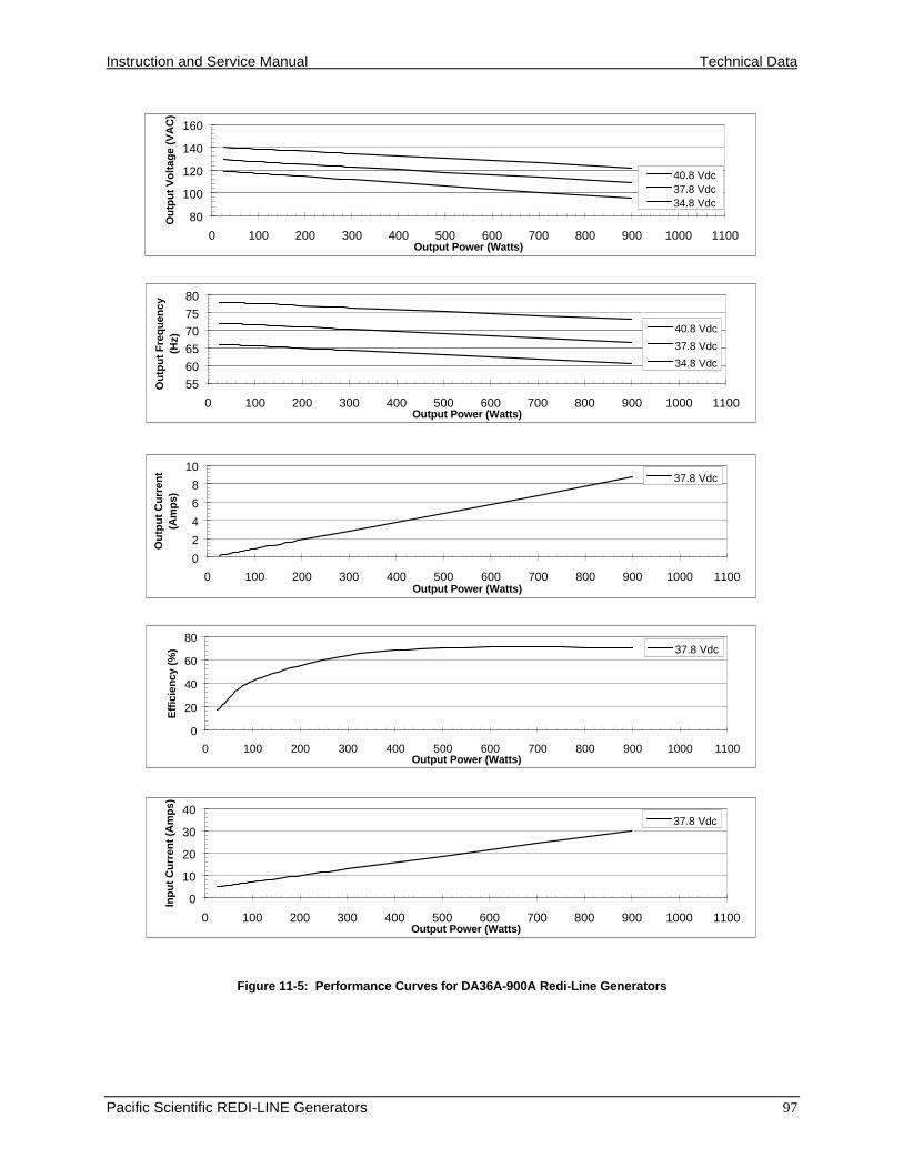
Instruction and Service Manual Technical Data
Pacific Scientific REDI-LINE Generators 97
Figure 11-5: Performance Curves for DA36A-900A Redi-Line Generators
80
100
120
140
160
0 100 200 300 400 500 600 700 800 900 1000 1100Output Power (Watts)
Ou
tpu
t V
olt
age
(VA
C)
40.8 Vdc37.8 Vdc34.8 Vdc
55
60
65
70
75
80
0 100 200 300 400 500 600 700 800 900 1000 1100Output Power (Watts)
Ou
tpu
t F
req
uen
cy
(Hz)
40.8 Vdc
37.8 Vdc
34.8 Vdc
0
2
4
6
8
10
0 100 200 300 400 500 600 700 800 900 1000 1100Output Power (Watts)
Ou
tpu
t C
urr
ent
(Am
ps)
37.8 Vdc
0
20
40
60
80
0 100 200 300 400 500 600 700 800 900 1000 1100Output Power (Watts)
Eff
icie
ncy
(%
) 37.8 Vdc
0
10
20
30
40
0 100 200 300 400 500 600 700 800 900 1000 1100Output Power (Watts)
Inp
ut
Cu
rren
t (A
mp
s)
37.8 Vdc
Related Documents