Department of Product and Production Development CHALMERS UNIVERSITY OF TECHNOLOGY Gothenburg, Sweden 2015 Redesign for cost reduction of cars interior Identification of opportunities and development of concepts Master’s thesis in Product Development KARIN HENRIKSSON MICHAELA KJELLANDER

Welcome message from author
This document is posted to help you gain knowledge. Please leave a comment to let me know what you think about it! Share it to your friends and learn new things together.
Transcript

Department of Product and Production Development CHALMERS UNIVERSITY OF TECHNOLOGY Gothenburg, Sweden 2015
Redesign for cost reduction of cars interior Identification of opportunities and development of concepts Master’s thesis in Product Development KARIN HENRIKSSON MICHAELA KJELLANDER

Redesign for cost reduction of cars interior
Identification of opportunities and development of concepts
KARIN HENRIKSSON
MICHAELA KJELLANDER
Department of Product and Production Development
CHALMERS UNIVERSITY OF TECHNOLOGY
Gothenburg, Sweden 2015

Redesign for cost reduction of cars interior Identification of opportunities and development of concepts
© KARIN HENRIKSSON, 2015 © MICHAELA KJELLANDER, 2015 Department of Product and Production Development Chalmers University of Technology SE-412 96 Gothenburg Sweden Telephone +46 (0)31 – 772 1000 Cover: Front page picture from volvocars.com (2015) Chalmers University of Technology, Gothenburg, Sweden 2015

Acknowledgements
We are very grateful for the opportunity to do the master's thesis at i3tex together with Volvo Car Corporation and we would like to thank them both for giving us this chance. We would also specifically want to thank our supervisors at i3tex, Ms. Sara Lindmark and Mr. Simon Andersson for sharing their knowledge and helping us throughout this thesis work. We would also like to give our deepest appreciations to our supervisor at Chalmers, Mr. Mattias Bokinge, for supporting us during this master’s thesis. He has been extremely helpful and made sure the project went in the right direction. We also want to thank each other for great cooperation and good company during this project. It has been very rewarding and joyful to perform this project and it is with great excitement and anticipation we can take our first steps into a new chapter of life.

Abstract The purpose of this master´s thesis is to identify an existing component with high potential for cost reduction from the interior of a car and redesign the component whilst maintaining or increasing its value for the customers. The goal is to demonstrate the potential for cost reduction of the selected component and present the concept to VCC for further development. For the project to be successful a reduced price per car of 21,7 ppm SEK should be demonstrated. The project follows the beginning of the VCC process together with the Concept Development & Selection Funnel as well as The Value Model. The terms customer value and cost reduction are explained. They serve as basic understanding for the project and the latter term constitutes the foundation for a framework of criteria for cost reduction used throughout this project. The project begins by finding a component with high potential for cost reduction through methods such as an evaluation matrix as well as relative decision matrices. The identified component is redesigned with focus on cost reduction whilst maintaining or increasing the customer value. Methods used for selecting concept with highest potential for cost reduction were an elimination matrix as well as guidance from a well experienced cost estimator. The outcome of this master´s thesis is that there is no solutions that can be implemented in the car in the near future. Recommendations for how the selected component can be designed when developing a new concept are instead proposed. Keywords: Customer value, Cost reduction, VCC, Redesign, Sun visor

1
Table of contents
1. Introduction ................................................................................................................................ 3
1.1 Cost reduction of existing products ........................................................................................ 3
1.2 Cost reduction for Volvo Car Corporation ............................................................................. 3
1.3 Purpose, goals and research questions .................................................................................... 3
1.4 Delimitations .......................................................................................................................... 4
1.5 Report outline ......................................................................................................................... 4
2. Theory.......................................................................................................................................... 5
2.1 Customer value ....................................................................................................................... 5
2.2 Cost reduction ......................................................................................................................... 6
3. Methodology................................................................................................................................ 7
4. Requirement phase ................................................................................................................... 10
4.1 Component requirement specification .................................................................................. 10
5. Searching phase one ................................................................................................................. 12
5.1 Line walk .............................................................................................................................. 12
5.2 Information gathering ........................................................................................................... 12
5.3 Creative methods for idea generation ................................................................................... 13
6. Evaluation phase one ................................................................................................................ 18
6.1 Component elimination matrix by Pahl & Beitz .................................................................. 18
6.2 Pugh matrix .......................................................................................................................... 18
7. Searching phase two ................................................................................................................. 20
7.1 Competitor analysis .............................................................................................................. 20
7.2 Workshop ............................................................................................................................. 22
8. Evaluation phase two ............................................................................................................... 25
8.1 Weighted Pugh matrix .......................................................................................................... 25
8.2 Choice of component ............................................................................................................ 25
9.1 Component structure............................................................................................................. 26
9.2 Function analysis .................................................................................................................. 28
9.3 Concept requirement specification ....................................................................................... 29
10. Idea generation phase ............................................................................................................ 30
10.1 Competitor analysis ............................................................................................................ 30
10.2 Creative methods for idea generation ................................................................................. 30
10.3 Concept structure matrix .................................................................................................... 31
11. Concept screening phase ........................................................................................................ 33

2
11.1 Concept elimination matrix by Pahl & Beitz ...................................................................... 33
11.2 Questionnaire ...................................................................................................................... 33
12. Concept refinement phase ..................................................................................................... 34
12.1 Further development ........................................................................................................... 34
12.2 Cost estimation ................................................................................................................... 36
12.3 Evaluation ........................................................................................................................... 36
13. Discussion ................................................................................................................................ 38
13.1 Overall process ................................................................................................................... 38
13.2 VCC process ....................................................................................................................... 38
13.3 Research questions ............................................................................................................. 38
13.4 Restrictions ......................................................................................................................... 39
14. Conclusions ............................................................................................................................. 40
15. Recommendations .................................................................................................................. 41
References ..................................................................................................................................... 42

3
1. Introduction This chapter explains the background to the project, the purpose and goals, the delimitations and the expected outcome of this master’s thesis work. The last part of the chapter explains the report outline.
1.1 Cost reduction of existing products The automotive industry is today heavily competitive and it is one of the most capital intensive businesses [1]. Sweden is one of the countries in the world that is the most depending on its automotive industry, around 100 000 people are active in the business and three large manufacturers are active within manufacturing and development [1][2]. It is therefore of considerable weight for Sweden that these companies keep a good position on the market. In this competitive environment one of the most important issues for a company is to focus on what their customers perceive as valuable. To achieve this, one of the main goals for these companies is to produce products with as many benefits for the customer as possible to a cost that is as low as possible. The customer value is the perceived economical, functional and psychological advantages that the customer expect from a product [3]. Customer benefits and costs are of course both in focus when developing new products and when redesigning already existing products. Today, many companies redesign their existing products especially for cost reductions [4]. Examples of such reductions can be to change the material of a component or change the design of a component to remove parts. The saved costs can for example finance new development projects within the company, can be used to offer the products at a lower price to the customers, or can be used to increase the profits for the company. Usually redesigned components are developed to fit in the existing production system with the available tools and machines to avoid unnecessary costs.
1.2 Cost reduction for Volvo Car Corporation This master’s thesis is carried out at the company i3tex for their customer Volvo Car Corporation, VCC. VCC is one of three automotive manufacturers that operates in Sweden and they are one of the strongest brands within the automotive industry [5]. VCC continuously redesign their existing products to increase their value but foremost to decrease costs. The reason why VCC is working with cost reduction is to finance future projects. However, VCC is very careful to increase or at least maintain the value for the customer. i3tex is a consultancy firm specialized in product development. The company is active within different industries and they provide technical expertise to their customers. The main strategy for i3tex is to develop products from an idea or vision using technical skills and creativity [6]. One of i3tex commitments to VCC is to lead cost reduction projects within the interior of cars.
1.3 Purpose, goals and research questions The purpose of the project presented in this master’s thesis is to identify potential for cost reduction in an existing VCC car, in order to free money. More specifically, the purpose is to identify an existing component with high potential for cost reduction from the interior of a car and redesign the component whilst maintaining or increasing its value for the customers. The project follows a VCC project template given by VCC together with methods selected from Ulrich & Eppinger [7] as well as The Value Model [8].

4
The goal is to demonstrate the potential for cost reduction of the selected component and present the concept with possibility to be implemented in the near future to VCC for further development. For the project to be successful a reduced price per car of 21, 7 per mille SEK should be demonstrated. This number is based on a plausible cost reduction per car and the total price per car.
This master´s thesis also attempts to answer the following research questions.
• How can a component with high potential for cost reduction be identified?
• How can the identified component be redesigned for cost reduction whilst maintaining or increasing the value for the customers?
1.4 Delimitations Since the project aims to present a concept for cost reduction, detailed development is excluded from the scope. The project is done at i3tex for the interior department at VCC which is why components other than the interior will not be included in the project. Components regarding safety and upholstery cannot be selected due to regulations at VCC.
1.5 Report outline Chapter two describes the theory and chapter three describes the methodology. Chapter four through chapter twelve explains the project including the choice of component and development of the concept. Discussion, conclusion and recommendations are found in the end of the report.

5
2. Theory This chapter presents important theories necessary for understanding this report. The theories explained are cost reduction and customer value.
2.1 Customer value Customer value can be defined as a relationship between perceived benefits and price. The customer value is how well the expectations and needs are fulfilled for the customer, and can be improved by adding more benefits and also by lowering the price for the customer. The production costs, development costs and the delivery costs does very rarely affect the customer value. Customer value is a subjective measurement based on comparisons made by customers between products available on the market [8]. The KANO model can be used to understand how the customer value can be increased, see Figure 1. The model has on the two axes customer satisfaction and degree of fulfillment and three curves that demonstrates different types of needs. The basic needs curve covers needs that are expected and unspoken. According to the KANO model are the basic needs for the customer unspoken and expected. If the basic needs are not fulfilled, the customer will be unsatisfied. The performance needs curve covers functions that are important and easy for the customer to express [8]. The excitements needs curve are functions that customers does not know they want but such function increases the customers satisfaction. The basic needs and the performance needs must be fulfilled to maintain the customer value. Adding additional unexpected functionality increase the customer value [8].
Figure 1, the KANO model

6
2.2 Cost reduction Cost reduction generates profit, but has to be done without negatively affecting customer value. It is a reliable way to generate profit which can be done continuously to secure future profits. Issues linked to cost reduction covers some central questions [4], see Table 1.
Table 1, Issues for cost reduction
Issues for lowering the cost of a product 1. Can we eliminate functions from the production process? 2. Can we eliminate some durability or reliability? 3. Can we eliminate unnecessary features? 4. Are specifications too tight? 5. Can we share parts with other products? 6. Can we minimize the design? 7. Can we shorten the design cycle time? 8. Can we design the product better for the manufacturing process? 9. Can we reduce the amount of scrap? 10. Can we substitute parts? 11. Can we tear down competitive products? 12. Can we combine steps? 13. Is there a better way?
It can be examined if parts can be shared between products. If this can be achieved, larger volumes can be produced of a particular part which entails lower price per part. A minimized design is another topic to evaluate. This is about designing the product with few parts and smallest amount of material, which means lowering cost of variants and material. Another focus is to design the product to fit the manufacturing process. This means that the product is designed so the manufacturing can be as effective as possible. Exchanging parts is another question to evaluate. This means finding components and materials that are less expensive than the existing ones used. It can be evaluated if there are any functions that can be eliminated from the production process. This implies an analysis of the manufacturing process to see if any steps can be eliminated that is not value adding. Another matter to evaluate is if the specifications for the products are set too high. Maybe there are some requirements that could be lowered that could reduce cost. Elimination of unnecessary parts of a component is can be realized through customer surveys. If a survey shows a part is not needed it might be possible to discard [4].

7
3. Methodology The project follows the beginning of a VCC project template used for cost reduction projects at VCC, Figure 2. Throughout the whole process as many solutions as possible are studied, as far in the process as possible, to later screen to deduce the most suitable solution.
Figure 2, the VCC process
The VCC project template is a Stage-gate [9] process that consists of four stages, Internal study, New, In process and Implemented. These are the stages a cost reduction project goes through before the change can be implemented in a car. Gates appears along the VCC project template, which needs to be passed in order to ensure compliance with the VCC standard requirements. For a project to pass a gate it must be approved at a meeting. The first of the gates, the PS gate, takes place at the end of the New stage. The proceeding gates appears during the In process stage and Implemented stage. This project includes the stages Internal study and New. The Internal study stage covers the finding of potential cost reduction components until the creation of concepts and the New stage covers development and refinement. In addition to the VCC project template, the process is inspired by two process models, selected by the team. The reason for adding these is that the VCC project template is only a frame to ensure potential for cost reduction and does not contain any methods for selecting components and developing concepts. The added methods are commonly used for product development and it was of interest to use these in a product development project with focus on cost reduction. These methods are the Concept Development & Selection Funnel by Ulrich and Eppinger and The Value Model. These are combined into a process suitable for this project.

8
The Concept Development & Selection Funnel by Ulrich and Eppinger is utilized in the project for screening, see Figure 3. The idea is to have a wide range of concepts in the beginning of the process and then systematically screen the concepts down until one or a few concepts remain. The screening process is done in steps, the first step is focusing on screening all the concepts that does not fulfill the needs in the Requirement specification. The next step Concept scoring is where the concepts get further screened through decision matrices [7].
Figure 3, Concept Development & Selection Funnel
The project is also inspired by The Value Model, see Figure 4. The steps are, Define the project, Plan the project, Establish the project control system, Analyze customer needs and create the concept, Design and verify the product and processes and Launch the new product and harvest the benefits. The main focus in this model is the customer value [8]. The steps used from this process is Define the project, Plan the project, Analyse customer needs and create the concept and Design and verify the product and processes.
Figure 4, The Value Model
9
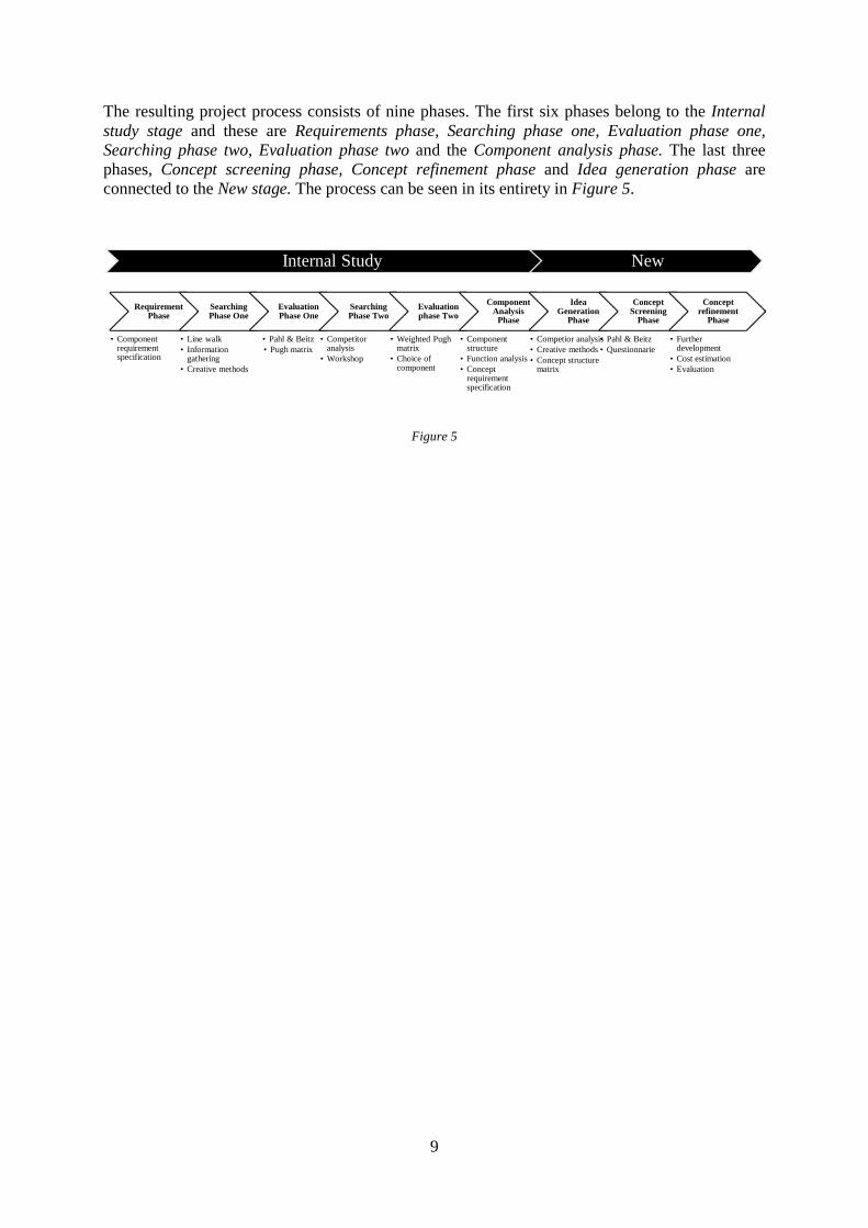
The resulting project process consists of nine phases. The first six phases belong to the Internal study stage and these are Requirements phase, Searching phase one, Evaluation phase one, Searching phase two, Evaluation phase two and the Component analysis phase. The last three phases, Concept screening phase, Concept refinement phase and Idea generation phase are connected to the New stage. The process can be seen in its entirety in Figure 5.
Figure 5
Internal Study New
Requirement Phase
• Component requirement specification
Searching Phase One
• Line walk• Information
gathering• Creative methods
Evaluation Phase One
• Pahl & Beitz• Pugh matrix
Searching Phase Two
• Competitor analysis
• Workshop
Evaluation phase Two
• Weighted Pugh matrix
• Choice of component
Component Analysis
Phase
• Component structure
• Function analysis• Concept
requirement specification
Idea Generation
Phase
• Competior analysis• Creative methods• Concept structure
matrix
Concept Screening
Phase
• Pahl & Beitz• Questionnarie
Concept refinement
Phase
• Further development
• Cost estimation• Evaluation
10
Requirement Phase
Searching Phase one
Evaluation Phase one
Searching Phase two
Evaluation phase two
Component Analysis
Phase
Idea Generation
Phase
Concept Screening
Phase
Concept refinement
Phase
4. Requirement phase During the Requirement phase, criteria that the selected component should meet was set up.
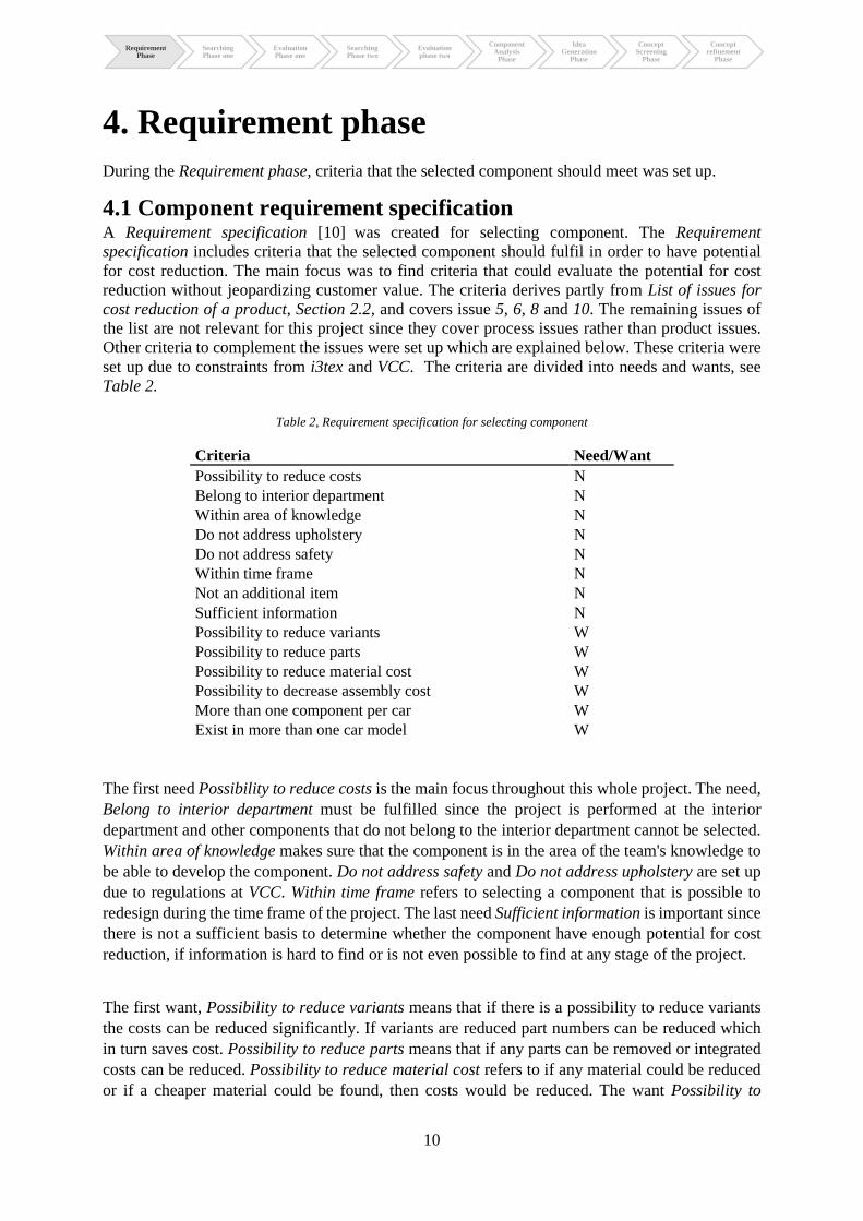
4.1 Component requirement specification A Requirement specification [10] was created for selecting component. The Requirement specification includes criteria that the selected component should fulfil in order to have potential for cost reduction. The main focus was to find criteria that could evaluate the potential for cost reduction without jeopardizing customer value. The criteria derives partly from List of issues for cost reduction of a product, Section 2.2, and covers issue 5, 6, 8 and 10. The remaining issues of the list are not relevant for this project since they cover process issues rather than product issues. Other criteria to complement the issues were set up which are explained below. These criteria were set up due to constraints from i3tex and VCC. The criteria are divided into needs and wants, see Table 2.
Table 2, Requirement specification for selecting component
Criteria Need/Want Possibility to reduce costs N Belong to interior department N Within area of knowledge N Do not address upholstery N Do not address safety N Within time frame N Not an additional item N Sufficient information N Possibility to reduce variants W Possibility to reduce parts W Possibility to reduce material cost W Possibility to decrease assembly cost W More than one component per car W Exist in more than one car model W
The first need Possibility to reduce costs is the main focus throughout this whole project. The need, Belong to interior department must be fulfilled since the project is performed at the interior department and other components that do not belong to the interior department cannot be selected. Within area of knowledge makes sure that the component is in the area of the team's knowledge to be able to develop the component. Do not address safety and Do not address upholstery are set up due to regulations at VCC. Within time frame refers to selecting a component that is possible to redesign during the time frame of the project. The last need Sufficient information is important since there is not a sufficient basis to determine whether the component have enough potential for cost reduction, if information is hard to find or is not even possible to find at any stage of the project.
The first want, Possibility to reduce variants means that if there is a possibility to reduce variants the costs can be reduced significantly. If variants are reduced part numbers can be reduced which in turn saves cost. Possibility to reduce parts means that if any parts can be removed or integrated costs can be reduced. Possibility to reduce material cost refers to if any material could be reduced or if a cheaper material could be found, then costs would be reduced. The want Possibility to

11
Requirement Phase
Searching Phase one
Evaluation Phase one
Searching Phase two
Evaluation phase two
Component Analysis
Phase
Idea Generation
Phase
Concept Screening
Phase
Concept refinement
Phase
decrease assembly cost means if costs connected to the assembly of a product can be reduced, cost will decrease. The want, More than one component per car is connected to the volume of components, the more of the same component existing in a car, the larger the possibility for cost reduction. The want Exist in more than one car model, is also connected to the volume of components in the same way as the previous requirement. The more components a vehicle are containing and the more models that component are available in, the higher the possibility to decrease cost.

12
Requirement Phase
Searching Phase one
Evaluation Phase one
Searching Phase two
Evaluation phase two
Component Analysis
Phase
Idea Generation
Phase
Concept Screening
Phase
Concept refinement
Phase
5. Searching phase one
During Searching phase one components with potential for cost reduction were found through a method called Line walk. The chapter further explains information gathering as well as creative methods.
5.1 Line walk The method for finding components with potential for cost reduction was a Line walk. A Line walk is a method where real products produced on a line are observed to create ideas on how to solve a certain problem. The advantage with performing a Line walk as a first method instead of studying a fully assembled car, drawings or CAD models is that it all components are available and perspicuous. In addition it is possible to see how it mounts to the car and to see components that are not visible in a fully assembled car. The objective for this activity was to find components in the interior of a car that have potential for cost reduction.
The line walk was performed during three hours at the VCC factory in Torslanda. The focus was to visit the pre-trim, trim and the door line areas since these are the areas where the interior parts are assembled. The Line Walk was performed together with one mechanical- and one development- engineer at i3tex and one manufacturing engineer at VCC.
It was of interest to note how the components were mounted to the car and if some components were hard to mount. Components were placed beside the line in boxes or standings and it was possible to examine the different components. The Requirement specification was used as a basis in order to find components with potential for cost reduction.
At certain stations questions were asked to the operators to get a deeper understanding about what they think of the operation and the components. These stations were, where the ceilings were prepared before mounted to the cars and the station where the tunnel console was mounted. These stations were chosen since they seemed especially complex at first sight. The questions and the outcome can be seen in Appendix A. A short meeting with all participants was held after the Line walk. All ideas of potential components were compiled and discussed. Totally 14 components with potential for cost reduction were found.
5.2 Information gathering Further investigation was necessary after the Line walk before the evaluation process could begin. This was needed in order to in a later phase evaluate the components and to select the component with the highest potential for cost reduction.
The information about the components that was collected included article price, assembly time, assembly cost, manufacturer, supplier, which car the component exists in, how many components exists in each car, where it is placed in the car, adjacent areas, volumes and material [4]. Drawings were studied to get a visual representation of the components and an understanding of how the components are composed.
A field study was done to collect information that could not be found in the office setting. It was useful to see the components a second time to get a deeper understanding of the components. The field study was performed through direct observation and included discussions and analyses of visible components in the car, therefore were only seven components evaluated. The components

13
Requirement Phase
Searching Phase one
Evaluation Phase one
Searching Phase two
Evaluation phase two
Component Analysis
Phase
Idea Generation
Phase
Concept Screening
Phase
Concept refinement
Phase
in focus were component B, C, F, G, I, L and N. Photos were taken of all the components for documentation and to be able to compare the different components for different car models. The visit gave a deeper understanding in how the components are used.
5.3 Creative methods for idea generation Creative methods were used to generate ideas for the potential in the components. When creating ideas for the potential, a method was used which is a different version of a Mind map [11] which is a common method for idea generation. The method was performed individually in order to avoid bias. The participants were given all information that was gathered so far in the project to be able find potential for the components. All components were written on a large white paper and during 20 minutes, ideas on what could be done to reduce cost was written down below each component, one at a time. It was important to remember that all ideas were important, even the crazy ones. After the individual method all ideas were discussed in group to gain more ideas. The ideas were compiled and the potential found for each component was documented. Each component and the potential found after Searching phase one are described in the following paragraphs. An overview can be seen in Table 3.
Table 3
Component Component name Function Potential
A Tyre well Cover spare tyre, abate sound and storage Reduce variants
B Handle Be able to lift up the boot floor Integrate, Reduce parts
C Plastic mounts to keep floor carpets in place
Keep the floor carpets in position
Remove clips, Change design
D Tunnel isolation with clip Abate noise
Remove clip, Cheaper material
E Tunnel isolation without clips Abate noise
Cheaper material, Reduce material, Remove clip
F Parking ticket holder Hold the parking ticket in position Change design
G Sun visor Protect against the sun Remove electricity, Change design
H Absorbents V60 & V60 Bi Fuel Absorb noise
Reducing variants, Material change, Remove clips
I Roof lining
Abate noise, cover the carriage body and hold electrical wiring looms Remove material
J Wheel arch isolation Abate noise Cheaper material, Reduce variants, Remove clips
K Isolation/absorbents in the boot Abate and absorb noise
Reduce variants, Reduce material
L Boot mat Protect from dirt and fluids Change design, Reduce material
M Center console Storage and to hold other components
Integrate parts, Change material
N Storage component Store articles Reduce variants, Reduce material

14
Requirement Phase
Searching Phase one
Evaluation Phase one
Searching Phase two
Evaluation phase two
Component Analysis
Phase
Idea Generation
Phase
Concept Screening
Phase
Concept refinement
Phase
Component A This component is the bowl which is located in the boot of the car and its functions are to cover the spare tyre, to lower the sound and to store belongings. The part is large and it is made of a felt material. The bowl has several trays for storing articles, such as a warning triangle, a reflective vest, a first aid kit and a cargo net. The function of the trays in the bowl is to make sure that the articles stay in position when the car is moving. The Volvo XC60, Volvo V70 and the Volvo XC70 were the car models in focus for this component since these cars have similar boot sizes and bowls. The potential for cost reduction in this component was to reduce variants by using the same bowl in many car models. Since the cars has similar boot sizes the same bowl could be used. Two variants of the bowl could be developed. For cars without space for a spare tyre the bowl could be flat to reduce the material. For the markets where a spare tyre is legally required in the car, a different variant could be created which could be shaped after the spare tyre. Component B The handle is located in the boot floor in the car. It is a small component consisting of two parts. One part is the actual handle and the other part is used to fasten the handle. Both of the parts consist of some sort of plastic. The function of this component is to give possibility to lift the boot floor. The handle exists in all the VCC cars except for Volvo V40, S60 and S80. The potential for this component was to integrate the two parts to one, this would have reduced variants as well as assemble time for the supplier. Additional potential for reducing cost is to remove the handle and integrate the handle in the boot floor. Component C This component is the mounts for the inlay mats. The function of this component is to keep the inlay mats in position. Two mounts are used for each carpet and they are attached to the seat isolation on the floor. Through holes in the carpet, it can be connected to the mounts. The holders are made of plastic and the carpets are made of rubber. This component exists in all VCC car models. For this component the potential is removal of the clips. Since there are eight in each car, there is a potential for cost reduction. The clips are necessary in the driver’s seat due to safety but could possibly be removed in the passenger’s seat or in the back seats. An idea is to have only one clip in the passenger seat and remove them from the back seats. If the clips are to be removed the floor mats need to be redesigned so that they do not move. Other ways of keeping the mat in place can be to fix them to the seats or change to a material with higher friction. They could be fastened to the floor with velcro or a clasp. Component D This component is a tunnel isolation with a clip which is placed under the tunnel console, between the two front seats. The function is to abate noise in the car. It belongs to the new version of the Volvo XC90. The isolation is made of a felt material and has one plastic clip placed on top of the isolation. It is a large component shaped to fit the entire area under the tunnel console. Around this clip a mark has been made with a white pen to assure quality. A possibility to reduce cost for this component is to remove the clip. Either there is a way to mount the component without a clip or there could be a split instead which could be fastened to a threaded metal bar. Otherwise a cheaper material could be used that isolates sound as good as the current material or better. Maybe there is a better way to mount the component to the vehicle.

15
Requirement Phase
Searching Phase one
Evaluation Phase one
Searching Phase two
Evaluation phase two
Component Analysis
Phase
Idea Generation
Phase
Concept Screening
Phase
Concept refinement
Phase
Component E The tunnel isolation without clips is placed under the tunnel console between the front seats. The function of the component is to abate noise in the car. The component has no clips and has a smooth surface. The material of the isolation is felt. It is shaped to fit the area under the tunnel console which makes it a large component. The biggest potential found for this component is to find a cheaper material that reduces the material cost and thereby the purchase price for the component. The surface looks unnecessarily aesthetically for not being seen. If the surface is not visible a less expensive material could be used for the surface. Another potential is to find a different way to mount the component to the vehicle in order to reduce the assembly time. A different design that does not require as much material as the current design could be done to save cost of material. The clips for this component are marked with a marker pen which is made due to quality assurance. If the clip can be removed the time spent marking around the clip will be reduced. Component F The parking ticket holder is used for holding parking tickets in the front window. The component is made as one part in a plastic material. To mount the parking ticket holder it is fixed between the window and the panel. This component exists in all VCC car models. This component was found mainly due to a quality problem. It sits loosely and is not mounted with any clips, glue or screws. After some usage it tends to loosen which creates an unwanted sound in the car. This part is already cheap to produce. Maybe the design can be change to prevent the unwanted sound and at the same time make it cheaper. The parking ticket holder is a component that is used in almost all cars at VCC. Component G The sun visor is located in the ceiling above the front seats in the car. The main function is to provide a possibility for the driver and the passenger to increase visibility in low sunlight. Other functions are to be able to look in a mirror and to give automatic light to the user meaning electricity is needed in the component. A lid covers the mirror when it is not used in order to protect the driver from light reflections in the mirror. It is possible to turn the sun visor around an axis to avoid the sun coming from different directions. The component is composed of several different parts made of different materials. The sun visor belongs to the Volvo XC60. The main potential for the sun visor is to remove the electricity. The electrical parts are very expensive as well as assembling them to the component. If it could be removed a great cost saving could be made. An initial idea for this is to move the lamp from the sun visor and place it in the ceiling instead. If the lamp is moved the frame and slot surrounding the current mirror and lamp might need to be redesigned. What is important if the lamp is going to be moved is to keep the automatic light when the slot is open. Also, consider other components might be affected if the electronics are moved. Another idea is that the lamp could be completely removed from the sun visor. Component H These components are absorbents, one which is used in the Volvo V60 and in the Volvo V60 Bi Fuel. These components are very similar to each other in shape and are made of the same felt material. The absorbents are placed above the rear wheel house on the left side. The function for the absorbents are to absorb sound so that the noise in the car is on a comfortable sound level.

16
Requirement Phase
Searching Phase one
Evaluation Phase one
Searching Phase two
Evaluation phase two
Component Analysis
Phase
Idea Generation
Phase
Concept Screening
Phase
Concept refinement
Phase
The potential for cost reduction for these components lies in combining the two components and thereby reducing to one variant. The two absorbents are very similar in shape which is why this could be possible. Maybe the material could be changed into a flexible material to fit the component to both car models. The absorbents have two clips each which are there for keeping the component in the right position. Either both clips could be removed or one is removed to ensure the attachment to the vehicle. The other could be replaced by a split in the absorbent which could fit to a threaded metal bar. Another idea is that the other clip could be exchanged to a hook. Another potential is to investigate if the same absorbent could be used in any other car than the Volvo V60 and Volvo V60 bi fuel. Around the clips it was marked with a black pen in order to assure quality, if the clips can be removed time will be saved due to that there is no longer a need to mark with pen. Component I The roof lining of the car is a large component that is made of backing to keep the shape of the ceiling and covered with fabric on the side that faces the inside of the car to give a nice surface. Cables are mounted on the backside of the ceiling with glue and paper stickers to make sure they stay in position. The function of this component is to abate sound, cover the carriage body and to hold the wiring looms. The ceiling exists in all VCC car models, the focus is on one of the car models. Regarding this component most potential lies in the assembly process. Many people worked on the same ceiling which led to many ceilings hanging in line waiting to be mounted into a car. Parts are mounted to the ceiling with glue. Glue might be expensive to buy and risks to destroy the inside part of the ceiling. Therefor it would be a potential to remove the glue and maybe use clips instead. Different clips that could be used are velcro clips, double-sided tape or fish hooks. Also the wiring looms and parts were covered with pieces of paper with glue on the inside which is time consuming and an unnecessary cost. Finding a way to remove them is a potential for cost reduction. If the glue is removed only these papers with glue could be used instead of clips. In order for the worker to know where to mount the electrical parts to the ceiling a laser marks where to mount them. There are already tracks in the ceiling so maybe the laser could be eliminated. Component J The wheel arch isolation is an isolation placed on the wheel arch in the back of the car. The function of this part is to prevent noise in the car. It is made in a felt material and exists in all car models of which one should be the focus. The component also has a clip. For this component the greatest potential lies in changing the material to a cheaper alternative. The component has clips which can be redesigned or removed. A different way to mount the component to the vehicle so that the assembly time shortens would reduce cost. If the same component could be used for the left and right side of the vehicle a variant could be reduced which would reduce cost. Component K These components are the isolations and the absorbents in the boot area. These are usually made from a pressed felt material. The function is to isolate and absorb noise that appears in the car. They are made in different shapes to fit the boot area and are shaped to overlap each other. These components exist in all VCC cars, the focus is on one car model. The main potential for this component is to find a different way to combine or integrate the isolators or absorbents in the boot in a way that requires less material or less variants. It is of interest to evaluate the material to find out if there are any alternatives with the similar properties but a lower purchase price. There is also potential in looking at possibilities to us the same component in different vehicles. Unnecessary overlap could be removed to reduce the amount of material.

17
Requirement Phase
Searching Phase one
Evaluation Phase one
Searching Phase two
Evaluation phase two
Component Analysis
Phase
Idea Generation
Phase
Concept Screening
Phase
Concept refinement
Phase
Component L This component is a mat located in the boot. It is an accessory that can be placed on the boot floor. It is a large component made of plastic that covers the entire floor and has edges on the sides. The function is to protect the boot floor from dirt and water. The component exists in the Volvo XC60. Changing the shape of the mat would be a potential if material could be removed. Changing the material into a cheaper would create potential for cost reduction. The present design covers the entire boot floor including the handle. A more visible handle may increase value to the customer as the current design is difficult to see. Also to remove material from the corner of the mat would favor the customer value since the mat can get trapped between the boot floor and the walls of the car when the boot floor opens. Component M This component is the tunnel console and consists of several different parts. It located between the two front seats. The main function of the component is to work as a storage area and to hold other components. It is mainly made out of plastic with metal details. This component exists in all VCC car models, the focus is on one car model. The line where the parts of the tunnel console are assembled is a new line that was implemented recently. Since the line was recently implemented there is a possibility that many areas have potential for cost reduction and that the different parts of the line have not yet had time to be evaluated or improved. Maybe there are possibilities to integrate parts of the tunnel console to minimize the assembly time and the steps in the assembly process. Another focus area could be to evaluate the materials used in the tunnel console to find out if any other material with a lower price could be used. Component N This is a storage component placed in the boot of the car, under the §. The function of this component is to give the possibility to store articles. The material of the component is styrofoam. This part can be used in the cars that do not have a spare tyre, instead this component is used. It is shaped to fit the area under the tyre well and has pockets for storing the articles. The potential for this component is to reduce variants by using the same storage box in many cars. Using less material or a lower density of the existing material would also be potential for cost reduction.

18
Requirement Phase
Searching Phase one
Evaluation Phase one
Searching Phase two
Evaluation phase two
Component Analysis
Phase
Idea Generation
Phase
Concept Screening
Phase
Concept refinement
Phase
6. Evaluation phase one
In this phase of the project the components found during the Line walk were evaluated and screened to be narrowed down to a few components for further evaluation. Matrices such as the elimination matrix by Pahl & Beitz [10] as well as the Pugh matrix [7] were used for the screening. The elimination matrix by Pahl & Beitz was used to eliminate the components that did not fulfil the needs in the requirements specification. After that, Pugh matrices were used to narrow the scope.
6.1 Component elimination matrix by Pahl & Beitz The first part of the Evaluation phase one was to screen the least promising components from the Line walk by using an elimination matrix by Pahl & Beitz. The components were assessed against the needs from the Requirement specification. The components got a (+), (-) or (?) on every need. A plus means that a component fulfils the need and a minus means it does not, a question mark means that more information is required. The components that got plusses on all needs passed the matrix and the components that got a minus on any need were eliminated. The components that got a question mark together with only plusses were further evaluated with more information. After further investigation, a decision was taken for the component to pass the matrix or to be discarded.
The needs for the matrix are Possibility to reduce costs, Belong to interior department, Within area of knowledge, Do not address upholstery, Do not address safety, Within time frame, Not an additional item and Sufficient information. Four components passed which were the components A, B, H and J. Seven components were eliminated which were the components C, D, E, F, L, M and N. Three components got a question mark as decision, which were component G, I and K.
The components that got the decision question mark were further evaluated and more information was collected. Component G was decided to continue with. Further research showed that the concern with the electricity was not overly complex. Component I was discarded. Possible cost saving for this component was to lower the assembly cost, which in this case is more of a process problem than a product problem. The last component with a question mark, Component K was eliminated because of the lack of information. All the information could not be found due to the time frame and because of its complex design.
Five components passed the elimination matrix, see Appendix B. These were the components A, B, G, H and J.
6.2 Pugh matrix After the elimination matrix the components were further screened in a Pugh matrix. This is a relative decision matrix in which the components were compared to a reference and the wants from the Requirement specification. The wants were Possibility to reduce variants, Possibility to reduce parts, Possibility to reduce material cost, Possibility to decrease assembly cost, More than one component per car and Exist in more than one car model. These criteria are all connected to the potential of the components which is why they can be compared against each other. Explanations of the criteria in the Requirement specification can be found in Section 4.1. The matrix was done three times with different references in order make sure that the result was similar independently of which reference that was used. This means that the components should be ranked approximately the same in each matrix to give a reliable result. The three reference components were A, G and I. To make the result more reliable, the matrices were done on different days to avoid influence from earlier results.

19
Requirement Phase
Searching Phase one
Evaluation Phase one
Searching Phase two
Evaluation phase two
Component Analysis
Phase
Idea Generation
Phase
Concept Screening
Phase
Concept refinement
Phase
If a component was significantly better at a criteria than the reference it got a plus, if it was significantly worse it got a minus and otherwise it scored a zero in the matrix. The sum of plus signs, zeroes and minus signs were counted and a net score could be calculated. With the net score as a base the components were ranked and the four components that were highest ranked in each matrix got a YES for approval, the rest got a NO and were thereby discarded. After the three matrices were done the result of each matrix was evaluated. The matrices can be seen in Appendix C. The result was similar in all three matrices and the components A, B, G and H passed while Component J was discarded.

20
Requirement Phase
Searching Phase one
Evaluation Phase one
Searching Phase two
Evaluation phase two
Component Analysis
Phase
Idea Generation
Phase
Concept Screening
Phase
Concept refinement
Phase
7. Searching phase two
During Searching phase two further information was gathered and more idea generation was done for the remaining components after the Pugh matrix. This was done through a competitor analysis and a workshop.
7.1 Competitor analysis A Competitor analysis was conducted in order to gain inspiration from what solutions competitors have and to get more input for ideas with potential for cost reduction. Cars in the same price class as the Volvo XC60 and in a lower price class were examined. The components examined all exist in the XC60 and therefore this car model was chosen. The car models that were examined in the same price class as the XC60 were the BMW X3, Mercedes GLK, KIA Sorento, Toyota RAV4, Volkswagen Tiguan and the Ford Mondeo. The car models in the lower price class were the BMW 1-serie, Mercedes A-class, KIA Rio, Toyota Yaris, Volkswagen Golf and Ford Focus. The reason why the competitor analysis was performed was to get a feeling for what standards are expected for each component in the same price class and to find solutions that are simpler and less expensive in the lower price class. The areas that were of interest for each component were the number of parts per car, number of fasteners, what material the component is made of and where it is placed in the car. Each component was examined according to these areas. Photos were taken from different angles to fully capture the solutions. Only three of the components remaining after the Pugh matrices, components A, B and G were examined since they are visible in the car. Component H is not a visible component and it was decided that this component should be looked up in a benchmarking database. Unfortunately there was no possibility to get access to this database which is why no benchmarking was done for the Component H. The following text explains the outcome of the Competitor analysis. Component A - same class The first component that was investigated was the tyre well. The tyre well in the different cars were very different, some car models did not have a tyre well and some had a tyre well for just a storage area for tools. It was also different whether the car had room for a spare tyre or not. The main focus for this component was to see if the other brand had a tyre well or not, the shape of the tyre well and space for spare tyre or not. The BMW X3 has a tyre well with small storage area with possibility to store several articles. The shape of the tyre well is relatively flat with different trays to be able to keep the articles organized. There is no space to store a spare tyre. The Mercedes GLK does not have a tyre well, instead the spare tyre and articles is stored just under the boot floor. There are different trays for articles as well as the spare tyre between the body and the boot floor. The solution for both the KIA Sorento and the Toyota RAV4 is similar to the Mercedes. The storage area is just under the boot floor with different trays but without a tyre well. The KIA Sorento does not have space for a spare tyre which Toyota RAV4 allows. The Volkswagen Tiguan has tyre well without any trays, it only covers the spare tyre. The shape of the tyre well are shaped after the spare tyre. The last car model, the Ford Mondeo does not have a tyre well, instead a styrofoam shaped part is used to store articles. The storage area does not allow any space for a spare tyre. The outcome can be seen in Appendix D1.

21
Requirement Phase
Searching Phase one
Evaluation Phase one
Searching Phase two
Evaluation phase two
Component Analysis
Phase
Idea Generation
Phase
Concept Screening
Phase
Concept refinement
Phase
Component A - lower class The BMW 1-serie did not have tyre well, just a storage area under the boot floor. The Mercedes A-class has a tyre well with trays for storing articles and under the tyre well is there space for a spare tyre. The material looks similar to the one XC60 has. The tyre well for the KIA Rio is also made in a similar material as the XC60 and the Mercedes. This tyre well has the shape of a spare tyre and there is a possibility to store a tyre under the tyre well. The Toyota Yaris and the Ford Focus did just have a boot floor to cover the area for the spare tyre with no tyre well. The Volkswagen Golf has the similar material in the tyre well that the XC60 has. The tyre well is deep and can fit a spare tyre if desired. The result can be seen in Appendix D2. Component B - same class The second component that was looked at was the handle to open the boot floor. The handles varied from the different car models, different solutions with different materials and different number of parts were common. Some models had complex solutions and some had easier solutions. The main focus for this component were, number of parts, material and if the solutions were complex or not. The handle for the BMW X3 is the same on both sides, the user needs to flick up the handle to get a grip to be able to pull the floor up or down. The component is made of plastic and it was estimated that the component has similar weight as the Volvo XC60. Mercedes GLK has a similar solution for the handle as the BMW on the upper side but is different on the other side. The solutions seems very complex on the bottom side. It is mounted to the boot floor with several screws and the part seems unnecessary big. This part also have another function, a string is attached to the bottom side which allows the user to fasten the boot floor to easier access the storage space. This handle is made from plastic and metal. Both KIA Sorento and Toyota RAV4 has the same type of handle, they have a string that is attached with a screw on the bottom side. It is a very simple design and the weight is less than the handle for the XC60. The handle for the Volkswagen Tiguan is very similar to the XC60, except the bottom side. The bottom side is just a piece of plastic which is less complex than most of the other handles except the ones with just a string. The handle for the Ford Mondeo is also similar to the BMW X3 except the bottom side. As a user you need to flick up the handle to lift up the boot floor. The result can be seen in Appendix D3. Component B- lower class It was a large spread of different solutions for the handle in the lower class. Both the BMW 1-series and the KIA Rio had their handle integrated in the boot floor. The solution for the BMW 1-serie was nicer looking then the solution for the KIA Rio. The handle for the Mercedes A-class and the Volkswagen Golf are similar to each other, they are both made in plastic and both have a solution that require the user to flick up the handle to be able to lift the boot floor. The Mercedes A-class also have a very advanced bottom part and an extra function which allows the user to hang the boot floor up since there is a hook attached to the handle. The Toyota Yaris and the Ford Focus also has a similar solution. They both have a string to lift the boot floor, this solution seems cheaper than the XC60. The result can be seen in Appendix D4. Component G - same class The last component that was evaluated in the same price class was the sun visor. The main focus for this component were the position of the light, the parking ticket holder, solution for covering the mirror, automatic light and material.

22
Requirement Phase
Searching Phase one
Evaluation Phase one
Searching Phase two
Evaluation phase two
Component Analysis
Phase
Idea Generation
Phase
Concept Screening
Phase
Concept refinement
Phase
The sun visor for the BMW X3 has a sliding lid with an automatic light placed in the roof lining. When the mirror is visible the automatic light turns on. The sun visor also has a parking ticket holder. The sun visor is made in fabric. Mercedes GLK sun visor also has the light in the roof lining with automatic light when the lid opens. The lid of this sun visor is similar to the XC60 except that the light is placed in the roof lining instead. The sun visor for the KIA Sorento does not have an automatic light, instead a button is placed in the roof lining to be able to turn the light on. When the sun visor is closest to roof lining the sun visor will get in contact with the button and turn the light off. This makes sure that the light never can be on when the sun visor is not used. The light is placed in the roof lining and this sun visor also has a parking ticket holder. A sliding lid is used, as found on the BMW X3. The sun visors for the Toyota RAV4 and for the Volkswagen Tiguan are very similar, they both have the light placed in the roof lining with automatic light. To cover the mirror a sliding lid is used. The last sun visor for the Ford Mondeo is similar to the XC60, it has the same kind of lid and two light on each side of the mirror. The light automatically turns on when the lid opens. The only difference between the sun visor XC60 has is that this sun visor has a parking ticket holder. The parking ticket holder for the Ford Mondeo is not placed in the same way as the other holders, this is integrated in the support hanger while the other has their holders integrated with the frame around the mirror. The result can be seen in Appendix D5.
Component G-lower class The sun visor for the BMW 1-serie and the sun visor for the Volkswagen Golf is similar due to the light placement in the roof lining and also due to the design of the lid. They both have automatic lights in the roof lining with a sliding lid but only the sun visor for the Volkswagen Golf has a parking ticket holder. The sun visor for the Mercedes A-class also has automatic light placed in the roof lining but the lid is similar to the XC60. Both the KIA Rio and the Toyota Yaris does not have any light. The KIA Rio has a sliding lid and a parking ticket holder which the Toyota Yaris does not have. The Toyota Yaris has a similar lid to the Volvo XC60. The sun visor for the Ford Focus has almost exactly the same design as the Volvo XC60. The result can be seen in Appendix D6.
7.2 Workshop A workshop was performed with the purpose to gain ideas for the remaining four components and to widen the perspective of the potential for the components. The Competitor analysis along with information gathered worked as input for the workshop. The main focus for the ideas was to decrease the cost whilst maintaining or increasing customer value. The workshop was performed during four hours divided into two sessions. In the first session, components A and B were in focus and components G and H at the second. People with different backgrounds and areas of competence were participating. They were divided into two groups. People with long work experience, other master’s thesis workers as well as people that recently graduated were participating. The background of the people was design, electronics, cost reduction, construction and IT. They were divided so that seven people were participating at each session. The first session started with an introduction about the purpose for the workshop. Shortly after that a warm-up game was performed to make the involved persons comfortable and creative. After the warm-up game the participants were given information about the components to understand the task. It was important that the information was sufficient for understanding the problem but should not lead the participants to a solution. The first component was presented and questions were answered for everyone to fully understand the component.

23
Requirement Phase
Searching Phase one
Evaluation Phase one
Searching Phase two
Evaluation phase two
Component Analysis
Phase
Idea Generation
Phase
Concept Screening
Phase
Concept refinement
Phase
After the information was given, individual idea generation was performed during four minutes. Individual idea generation is used to avoid the participant being affected by bias. Each participant were provided with papers and pens to note their ideas. After this individual session the main method was performed which was a mind map. In this type of method quantity goes before quality. This makes the participants think outside the box which gives a different view of the problem and might lead to new good ideas. The method was performed during 20 minutes. The group was divided into two which got one large white paper each. The mind map was done by writing the component in the middle of the paper with all the ideas written around. Colored pens and post-it notes were used and the participants were more than welcome to draw their ideas and discuss them to get creative and come up with many ideas. After finishing the mind maps the ideas were presented and discussed. After the workshop was performed all ideas were collected and organised in different documents, one for each component. At first all duplicates were removed and all ideas and more developed concepts were written down in a document. The ideas and the more developed concepts were explained in detailed as much as possible in this stage. Component A The ideas generated about this component were for instance to combine the tyre well in different cars models to reduce variants. Ideas about how to do trays were also generated, movable walls with velcro could be used to customise the tyre well with trays. It was also discussed to remove the whole tyre well and instead keep the articles under the boot floor or in the boot area. All ideas can be seen in Appendix E1. Component B Different ideas were generated for the handle, with several about how to eliminate the handle and integrate it in the boot floor. One idea was to press a tyre well into the boot floor and cut the end towards the rear end of the car to be able to grab the floor to open it. Another idea about how to integrate the handle in the boot floor was to cut off some material in the boot floor to give the user the possibility to grab the floor to lift it up. One other idea was the remove the existing handle and keep the hole, fabric could be used on the bottom side to prevent articles items etc. from falling down and also to prevent seeing down to the tyre well. If the handle was removed a metal stick could be used as a handle to make it easier to grab. All ideas can be seen in Appendix E2. Component G The ideas for the sun visor were many, several were about find cheaper materials, reduce material and also different solutions for where to place the light. Different designs for the sun visor were also generated, such as different lid designs as well as for the whole sun visor. All ideas can be seen in Appendix E3. Component H The ideas generated for the absorbents were mostly focusing on how the clips could be removed and how the absorbent could be mounted instead. Ideas instead of having clips were for instance to make a slit where the clips are today and mount it with a threaded metal bar. The threaded metal bar would be mounted in the body of the car. Other ideas of clips that could be used were velcro, hooks and also reduce one clip and just have one. Other ideas such as integrate the absorbent to the inner panel and also that a flexible material could be used with some sort of glue so it glues to the body.

24
Requirement Phase
Searching Phase one
Evaluation Phase one
Searching Phase two
Evaluation phase two
Component Analysis
Phase
Idea Generation
Phase
Concept Screening
Phase
Concept refinement
Phase
Another idea that already has be discussed is to combine the absorbents for the Volvo V60 and for the Volvo V60 Bi fuel. Ideas how to make those absorbents to fit in both the Volvo V60 and the Volvo V60 bi fuel were to use a flexible material that easily conforms and fit both car models. All ideas can be seen in Appendix E4.

25
Requirement Phase
Searching Phase one
Evaluation Phase one
Searching Phase two
Evaluation phase two
Component Analysis
Phase
Idea Generation
Phase
Concept Screening
Phase
Concept refinement
Phase
8. Evaluation phase two
Evaluation phase two explains how the final component was selected in a Weighted Pugh matrix [10].To make sure the final component goes with the direction VCC expects this project to take, the actual choice of component was made at a meeting at VCC.
8.1 Weighted Pugh matrix A Weighted Pugh matrix was used to further screen the remaining components. This matrix is similar to the Pugh matrix. The same criteria, which are the wants from the Requirement specification, were used in this matrix, see Section 4.1. The difference is that each want is given a certain weight according to its importance for the outcome. The wants were weighed from one to five, where five represents the most important and one represents the least important. The weighting is multiplied by the score the component is given for each criteria. The wants Possibility to reduce variants, Possibility to reduce parts, Possibility to reduce material cost and Possibility to decrease assembly cost all have weight 3. These are of equal importance for cost reduction which is why they are weighted the same. Components per car and Existence in car models are both wants that are related to the volume of a component. These might have a great impact on the potential for cost reduction and are therefore weighted 4. The net score was calculated and the component with the highest score in each matrix got the highest rank, the highest rank means rank one. The component that was highest ranked totally after the three Weighted Pugh matrices was the one to continue with. The result of the matrices all showed that Component G is the component with most potential for cost reductions. The components A, B and H were discarded. The result can be seen in Appendix F.
8.2 Choice of component A meeting at VCC was arranged in order for VCC to approve the selected component after the Weighted Pugh matrix. The component with the most potential for cost reduction, Component G, was taken to the meeting. The components with second and third most potential, Component B and Component H, were also brought in case the chosen component was not approved. Appropriate information along with the potential for each component was required for this meeting.
A presentation was held at the meeting about the components to explain the potential. With that as a base a discussion was held to reach a decision. The people involved in this meeting were people from different departments to cover the knowledge about every component. The competencies that participated were Part project leader, Luggage trim manager and Concept developer for interior trim. The Manager headlining, carpets and NVH parts who is in charge of the sun visor was not present at the meeting. A decision to continue with the sun visor was taken and all participants agreed that this was the best component to continue working with. During the meeting it was also decided that it was better to focus on the new Volvo XC90 since this is a new car and might have more potential for cost reduction than the Volvo XC60. The decision from the involved people was based on their previous experience within cost reduction and also what they know is possible to accomplish within the time frame.

26
Requirement Phase
Searching Phase one
Evaluation Phase one
Searching Phase two
Evaluation phase two
Component Analysis
Phase
Idea Generation
Phase
Concept Screening
Phase
Concept refinement
Phase
9. Component analysis phase After the component was chosen the project went into the Component analysis phase. In this phase the component was disassembled and a Function analysis was made. Finally a Requirement specification for the sun visor was set up. The sun visor can be seen in Figure 6.
Figure 6, the sun visor
9.1 Component structure Two sun visors were disassembled in order to map their respective parts, see Appendix G, Figure 8. The sun visors were of different colours and one right and one left sun visor to be able to see the differences between them. The sun visor consists of eleven main parts which are Surface material, Light, Electronics, Padding, Mirror, Frame, Glue, Skeleton, Cover for light, Silencer and Lid are described below. A picture of how the parts are assembled can be seen in, Figure 7.
Figure 7, parts of sun visor

27
Requirement Phase
Searching Phase one
Evaluation Phase one
Searching Phase two
Evaluation phase two
Component Analysis
Phase
Idea Generation
Phase
Concept Screening
Phase
Concept refinement
Phase
A. Surface material The surface material is a laminate with fabric on the surface, foam beneath and closest to the padding is a gauze. The gauze has adhesive on the side that faces the padding to make it easier to fit and keep in place on the padding. B. Light The light in the sun visor is a LED light. There is one in each sun visor which is placed on the side of the mirror see Appendix G, Figure 5. C. Electronics A copper plate along with a resistor, a light and wiring looms represents the electronics in the sun visor. The electronics is fastened to a plastic plate which is connected to the frame with clips to keep it stable, see Appendix G, Figure 2. This part can be used for both the right and the left sun visor since it is mirrored. The copper plate that is used to conduct electricity is fastened in the plastic plate and is also mirrored, see Appendix G, Figure 7 and 11. The light can therefore be placed on either the left or the right side. D. Padding The padding in the sun visor is made of expanded polypropylene and it is made in two parts that are glued together. The two parts of padding fits perfectly around the skeleton. E. Mirror Between the frame and the plastic plate with the electronics, the mirror is fixed, see Appendix G, Figure 5. The mirror is made of glass and on the backside of the mirror a bit of paper is glued. F. Frame The frame holds the plastic plate for the electronics, the light, the mirror and the lid. A ticket holder is integrated in the frame, see Appendix G, Figure 9. This part is made in polypropen. The frame is mounted to the skeleton with clips that are molded in the back of the frame, see Appendix G, Figure 1, 2, 3 and 4. G. Glue The glue is used to fixing the two parts of padding together as well as the surface material.
H. Skeleton The skeleton is the base for the sun visor which is used to keep the sun visor steady. It is made in polybutylene terephthalate. The skeleton is made in different colors depending on the color of the roof lining in the car. It has six clips on which the frame is mounted, see Appendix G, Figure 1 and 3. The skeleton measures ten millimeters on its widest part and seven millimeters on its thinnest part. The sun visor is thereby bent three millimeters on the side facing the roof lining and straight on the side facing the windscreen, see Appendix G, Figure 10. I. Cover for light The lens is mounted with clips to the plastic plate that holds the electricity. The lens is used to spread the light. It is made of polycarbonate and the plastic is frosted. The lens is the same part for left and right sun visor, see Appendix G, Figure 6.

28
Requirement Phase
Searching Phase one
Evaluation Phase one
Searching Phase two
Evaluation phase two
Component Analysis
Phase
Idea Generation
Phase
Concept Screening
Phase
Concept refinement
Phase
J. Silencer A rubber strip is attached to the lid to lower the sound when the user closes the lid. The rubber strip is injection molded to the lid. K. Lid The lid is mounted to the frame and the main function is to cover the mirror. It is made in polypropen. It is connected so that when the lid opens it pushes a switch in the electronics to turn the light on and off. On the edge of the lid some lines are shaped. The function of these are to avoid slippage when opening the lid.
9.2 Function analysis A Function analysis was created in order to get an overview of the functions of the sun visor. Each function is expressed as verbs and nouns, in a neural formulation, which means that the formulation tells what the solution should do not how the solution should do it [8].
Information about the functions was gathered during the disassembly of the sun visor and through a requirement specification from VCC.
A hierarchical function structure was created, see Appendix H. The main function of the sun visor is to Shade sun. Thereafter follows five sub functions. These are Reflect image, Handle automatic light, Inform driver, Cushion sounds and Adjust sun visor.
The function Reflect image comes from that the existing sun visor has a mirror for the user to look in. A function related to Reflect image is Prevent reflections. Since the sun visor should be able to reflect images it must also be able to protect against disturbing reflections from lights.
The function Handle automatic light requires the functions Turn light on and Turn light off. In the current solution turns the light automatically on when the lid opens and turns off when the lid closes. It must be possible to turn the light on and off due to safety reasons so that the driver does not risk to become dazzled and also to save battery in the car.
Inform driver refers to the airbag in the car of which the driver must have knowledge about. This is a necessary function due to legal regulations.
Cushion sounds is a function that mutes the sound coming from the lid in the existing sun visor. If there are any similar lids in the new solution this function must be included.
Connected to the function Adjust sun visor were the functions Rotatable sun visor, Angle sun visor and Hold position. It must be possible to adjust the sun visor into the desired position. The sun visor must stay in position until it is moved again, regardless of rotation and angles set by the user.

29
Requirement Phase
Searching Phase one
Evaluation Phase one
Searching Phase two
Evaluation phase two
Component Analysis
Phase
Idea Generation
Phase
Concept Screening
Phase
Concept refinement
Phase
9.3 Concept requirement specification A Requirement specification for selecting concept was created. This Requirement specification includes wants and needs that the final concept needs to fulfil, see Table 4. All criteria set up in this Concept requirements specification are not the same as in the Components requirements specification, Section 4.1, since these criteria are used for concepts instead of components.
Table 4, Requirement specification for selecting concept
Criteria Need/Want Possibility to reduce costs N Maintain customer value N Fulfil VCC requirements N Clear description of idea N Realizable N Sufficient information N Implementable in near future N Possibility to reduce variants W Possibility to reduce parts W Possibility to reduce material cost W Possibility to decrease assembly cost W Little need for change of tools W
The needs set up in the concept requirement specification were Possibility to reduce cost, Maintain customer value, Fulfil VCC requirements, Clear description of idea, Realizable and Sufficient information. The needs Possibility to reduce costs and Sufficient information are explained in Section 4.1. Maintain customer value is another important need. The customer value should be maintained or increased in order for a concept to be suitable for further development. Fulfil VCC requirements refers to requirements set up by VCC regarding safety and technique that the sun visor must meet for the possibility to be implemented into a car. The need Clear description of idea means that a concept must be well defined and understandable in order to be developed further. Realizable is a need that determines whether a concept is technically realizable which is necessary for further development. The wants were Possibility to reduce variants, Possibility to reduce parts, Possibility to reduce material cost, Possibility to decrease assembly cost and Little need for change of tools. The four first mentioned are explained in the Components Requirement specification, Section 4.1. The last want Little need for tool changes is important since tool changes are very costly.

30
Requirement Phase
Searching Phase one
Evaluation Phase one
Searching Phase two
Evaluation phase two
Component Analysis
Phase
Idea Generation
Phase
Concept Screening
Phase
Concept refinement
Phase
10. Idea generation phase This step includes a competitor analysis, creative methods to generate ideas and creation of a Concept structure matrix.
10.1 Competitor analysis The New XC90 is more expensive than the XC60, which earlier was the focus, so a new competitor analysis was needed in order to compare the sun visor under equal conditions, see Section 8.2. The car models that the sun visor was compared to were the Mercedes GL, Audi Q7 and BMW X6. These were selected since they are in the same price class. This competitor analysis was performed at different car stores in the Gothenburg area. The main focus for this competitor analysis were the surface material, position of light, number of lights, automatic light, solution for covering the mirror, if there is a ticket holder and how it is put together. The first car model that was investigated was the Mercedes GL, this sun visor is made of vinyl and the roof lining of the car is made from fabric. For covering the mirror a lid that is of the same kind as the Volvo XC90 is used. The light is placed in the roof lining and turns on automatically when the mirror is visible. To avoid sound when closing the lid two rubber pieces are used as a silencer. Those two pieces are placed on the bottom of the frame. A holder ticket is integrated to the frame in the same way as for the Volvo XC90. The sun visor for left and right are different, as the ticket holder is on different sides. It looks like the sun visor is in two parts that are probably glued together. The second sun visor viewed was the Audi Q7’s. This sun visor is made in fabric and the roof lining is also made in fabric. The ticket holder for this sun visor is different from both the Volvo XC90 and the Mercedes GL, instead of having a integrated plastic holder this sun visor has a piece of fabric to be able to store notes and cards. The light is placed around the mirror in the shape of a square and is also automatic when the mirror is visible. The lid to cover the mirror is designed as a sliding lid. The sun visor for the left side and the right side are different, the sliding door open from different sides and the ticket holder is also on different sides. From what can be seen on the sun visor it looks like it is assembled as two parts. The last sun visor that was investigated was the BMW X6 which also is made from vinyl with the roof lining in fabric. The ticket holder is integrated in the same ways as for the Volvo XC90 but with more material. A sliding lid is used to cover the mirror and the light is also automatic when the mirror is visible. This sun visor is also done differently for the right and the left side. As for the other sun visors it looks like this one is assembled in the same way as the others. The outcome from the competitor analysis can be seen in Appendix J.
10.2 Creative methods for idea generation To generate ideas for how to redesign the sun visor, creative methods such as individual idea generation and Mind maps were combined. As a first step, Mind maps were created individually. A timer was set to ten minutes and during this time every idea that came up about the sun visor was written on large, white papers. Pens of different colours and post-it notes were used to establish a creative environment. All types of ideas were allowed which increased the possibility of coming up with many ideas. After the session was completed all the ideas were discussed within the team to generate even more ideas.
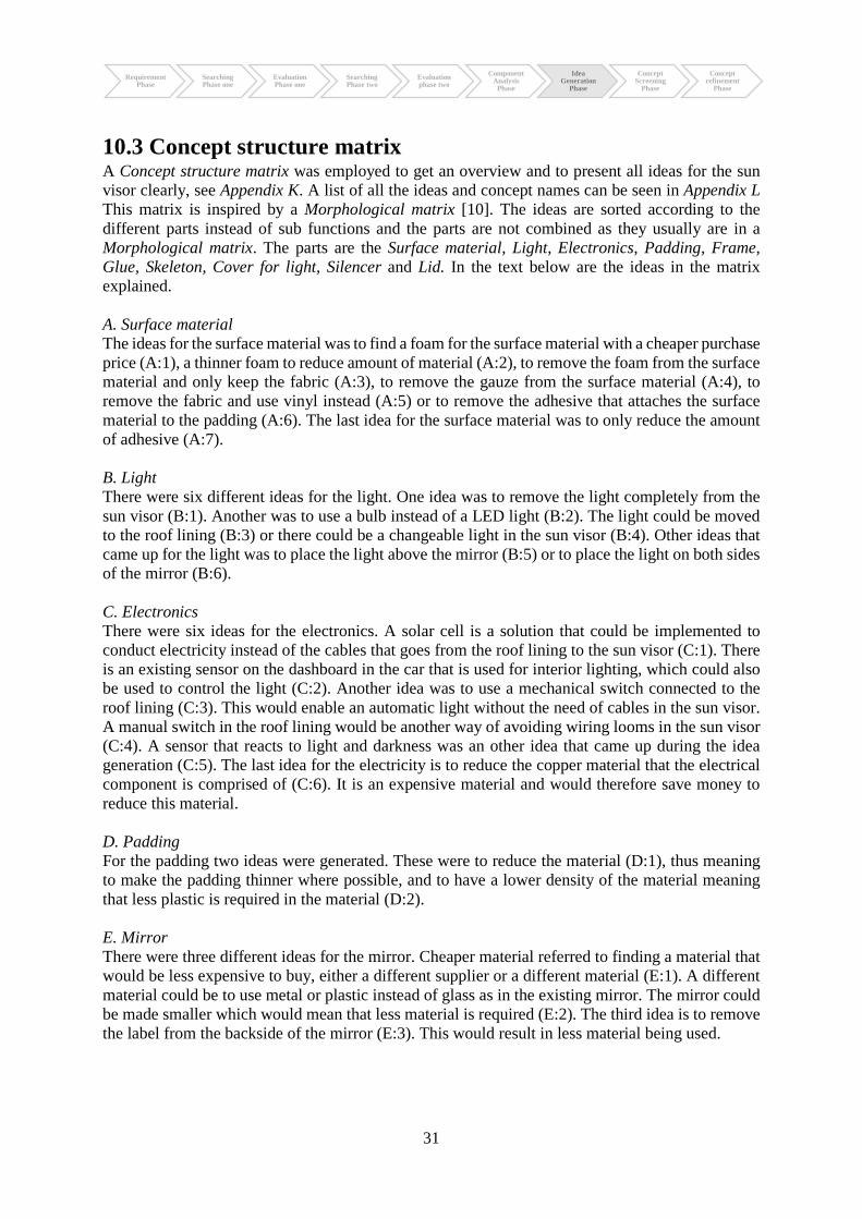
31
Requirement Phase
Searching Phase one
Evaluation Phase one
Searching Phase two
Evaluation phase two
Component Analysis
Phase
Idea Generation
Phase
Concept Screening
Phase
Concept refinement
Phase
10.3 Concept structure matrix A Concept structure matrix was employed to get an overview and to present all ideas for the sun visor clearly, see Appendix K. A list of all the ideas and concept names can be seen in Appendix L This matrix is inspired by a Morphological matrix [10]. The ideas are sorted according to the different parts instead of sub functions and the parts are not combined as they usually are in a Morphological matrix. The parts are the Surface material, Light, Electronics, Padding, Frame, Glue, Skeleton, Cover for light, Silencer and Lid. In the text below are the ideas in the matrix explained. A. Surface material The ideas for the surface material was to find a foam for the surface material with a cheaper purchase price (A:1), a thinner foam to reduce amount of material (A:2), to remove the foam from the surface material and only keep the fabric (A:3), to remove the gauze from the surface material (A:4), to remove the fabric and use vinyl instead (A:5) or to remove the adhesive that attaches the surface material to the padding (A:6). The last idea for the surface material was to only reduce the amount of adhesive (A:7). B. Light There were six different ideas for the light. One idea was to remove the light completely from the sun visor (B:1). Another was to use a bulb instead of a LED light (B:2). The light could be moved to the roof lining (B:3) or there could be a changeable light in the sun visor (B:4). Other ideas that came up for the light was to place the light above the mirror (B:5) or to place the light on both sides of the mirror (B:6). C. Electronics There were six ideas for the electronics. A solar cell is a solution that could be implemented to conduct electricity instead of the cables that goes from the roof lining to the sun visor (C:1). There is an existing sensor on the dashboard in the car that is used for interior lighting, which could also be used to control the light (C:2). Another idea was to use a mechanical switch connected to the roof lining (C:3). This would enable an automatic light without the need of cables in the sun visor. A manual switch in the roof lining would be another way of avoiding wiring looms in the sun visor (C:4). A sensor that reacts to light and darkness was an other idea that came up during the idea generation (C:5). The last idea for the electricity is to reduce the copper material that the electrical component is comprised of (C:6). It is an expensive material and would therefore save money to reduce this material. D. Padding For the padding two ideas were generated. These were to reduce the material (D:1), thus meaning to make the padding thinner where possible, and to have a lower density of the material meaning that less plastic is required in the material (D:2). E. Mirror There were three different ideas for the mirror. Cheaper material referred to finding a material that would be less expensive to buy, either a different supplier or a different material (E:1). A different material could be to use metal or plastic instead of glass as in the existing mirror. The mirror could be made smaller which would mean that less material is required (E:2). The third idea is to remove the label from the backside of the mirror (E:3). This would result in less material being used.

32
Requirement Phase
Searching Phase one
Evaluation Phase one
Searching Phase two
Evaluation phase two
Component Analysis
Phase
Idea Generation
Phase
Concept Screening
Phase
Concept refinement
Phase
F. Frame To reduce cost for the frame three ideas were generated. One was to remove the ticket holder which would mean that less material is required (F:1). Another idea was to reduce the amount of material used in the frame and thereby giving simpler form (F:2). A third alternative was to remove the frame so that so that less material is required (F:3). G. Glue Two ideas was generated for the glue. One idea was to reduce the amount of glue since a large quantity of glue is used in the existing solution (G:1). This would mean a lower material cost. Instead of the existing one another cheaper glue could be used, from a different supplier (G:2). This would require finding an adhesive with the same properties as the existing. H. Skeleton Four alternatives were found for reducing cost in the skeleton. The amount of material in the skeleton could be reduced meaning less costs for material (H:1). The same skeleton could be used both for the left and the right sun visor (H:2). In the existing skeleton there are six clips that holds the frame, these could possibly be reduced to five or four which leads to less amount of material being used (H:3). Another alternative is that a cheaper material could be applied for the skeleton (H:4). I. Cover for light For this part of the sun visor two different ideas were generated which were to reduce material (I:1) or to use a cheaper material (I:2). The first mentioned refers to using less material so that the cover becomes thinner. Cheaper material means finding an alternative with the same properties or a different supplier for the same material that can offer a lower price. J. Silencer There was one idea for cost reduction for the silencer. It was to remove the silencer which would mean a reduction of material (J:1). K. Lid Three ideas for the lid were generated. An idea for the lid was to remove these lines since the function is not necessary (K:1). Another idea for the lid was to remove the lid completely (K:2). This would mean that there is no possibility to cover the mirror which needed to be taken into consideration. Removal of the lid would mean part reduction and less material would be used. A third idea was to have a sliding lid (K:3).

33
Requirement Phase
Searching Phase one
Evaluation Phase one
Searching Phase two
Evaluation phase two
Component Analysis
Phase
Idea Generation
Phase
Concept Screening
Phase
Concept refinement
Phase
11. Concept screening phase After creating concepts for the sun visor the Concept screening phase began. In this phase the elimination matrix by Pahl & Beitz was used as a screening method to select a final concept.
11.1 Concept elimination matrix by Pahl & Beitz The elimination matrix by Pahl & Beitz was used for screening of the concepts, see Appendix M. The execution was the same as earlier described, see Section 6.1. The criteria used in this matrix are the needs from the Requirement specification set up for the new concept. The different needs are Possibility to reduce costs, Maintain customer value, Fulfil VCC requirements, Clear description of idea, Realizable and Sufficient information. The concepts evaluated in the matrix were both concepts that could be implemented in a reduced or extended time frame. None of the concepts passed the matrix. Three concepts scored plusses on all needs but Implementable in near future. These were concept C:1, H:2 and K:3. Even though the goal throughout this project was to find a concept for redesign that could be implemented in the near future, these concepts have potential for implementation further in the future since they fulfilled every other need.
11.2 Questionnaire A Questionnaire was done to investigate what the users finds important and how alterations in the sun visor affects the user. The questions in the questionnaire are set up as closed-ended questions which means that the questions have options that the participant pick [12]. In total 29 people in the age group 18 and older, having a driver's license and driving regularly answered the survey. The questions asked and the result can been seen in Appendix I. Question 1 shows that the usage of the mirror in the sun visor varies from using it every day to never use it, but most people use it rarely. Question 2 refers to the usage of the ticket holder and has a clear result. The ticket holder is not used at all or is rarely used. Question 3 shows that a there is not any need for a parking ticket holder in the sun visor.

34
Requirement Phase
Searching Phase onw
Evaluation Phase one
Searching Phase two
Evaluation phase two
Component Analysis
Phase
Idea Generation
Phase
Concept Screening
Phase
Concept refinement
Phase
12. Concept refinement phase This phase of the project includes concept refinement of the concepts that have potential for cost reduction when implemented further in the future.
12.1 Further development The three concepts with high potential for cost reduction if they are implemented in the future were further developed and are explained in the following text. Concept C:2 The concept is to use a solar cell that could be introduced to conduct electricity instead of the cables that go from the roof lining to the sun visor. The solar cell could be placed on the side that is facing the windscreen so that sunlight can reach the unit when it is tilted towards the windscreen. The solar cell should be connected to a rechargeable battery to store the electricity. This would require a battery with a long life span that can handle low temperatures as well as higher temperatures for several hours. To implement a solar cell would mean that the padding as well as the electrical parts needs to be redesigned. The concept can be seen in Figure 8.
Figure 8, Concept, solar cell
A solar cell is a desirable idea as the wires that go from the roof lining to the sun visor would not be needed. They are very expensive and entails long assembly time which is why costs would be reduced if they were removed. This concept might have a positive effect on the customer value since it is a solution that adds to an environmental friendly approach for VCC. In addition, a solar cell is something new that has not appeared in a sun visor on the market before. Further research was conducted to get a deeper understanding about how solar cells function. Issues that needed to be answered were if the solar cell is suitable in extreme temperatures and if there are batteries with long enough life spans. Concept H:2 This concept is about designing the skeleton in the sun visor so that it can be used for both the left and the right sun visor. There are two areas of the skeleton that differs between the right and the left sun visor. These are the construction of the clips and the bend on one side of the skeleton. The clips that are used to mount the frame needs to be redesigned so that it is possible to mount the frame on both sides of the sun visor. This could be done by changing the construction of the clips and place them in the middle of the skeleton. Another part that needs to be changed is the shape of the skeleton itself. The existing solution is bent on one side to make the sun visor fit the roof lining when it is positioned towards the roof lining. Also, the bend needs to be redesigned so that it can be used in both the right and the left sun visor positions. To be able to use the same skeleton for the right and left sun visor it would need to be bent on both sides. The skeleton should be equally bent on the

35
Requirement Phase
Searching Phase onw
Evaluation Phase one
Searching Phase two
Evaluation phase two
Component Analysis
Phase
Idea Generation
Phase
Concept Screening
Phase
Concept refinement
Phase
side facing the windscreen as on the side facing the roof lining. This would be realized if the widest part remains ten millimetres and the thinnest part of the skeleton would be reduced from seven to six millimetres. Then the skeleton could be bent two millimetres on each side. As an effect of changing the bend, the shape of the padding needs to change so that the sun visor still fits correctly to the roof lining. The existing sun visor and the new concept can be seen in Figure 9 and in Figure 10.
Figure 9, Sun visor today Figure 10, New concept
This concept would shorten the production time and cost of tools would be lower since the same tool can be used for both right and left. Since this concept requires changes in the tools it is not possible to do this change now so this concept is mainly for the future when new sun visors will be constructed. Designing these parts to fit both the right and the left sun visor would mean lower investment costs for the tooling since it is possible to manufacture one tool instead of two. In addition the time for changing tools would be reduced since the same tools is used. The time for developing a sun visor that fits both the right and the left side of the car would also be shorter since only one design is needed instead of two. Removing the ticket holder is preferable to since it saves material. Concept K:3 This concept is to design a sliding lid which would mean that the same lid and parts connected to the lid could be used in both the right and the left sun visor, see Figure 11. The other affected parts are the plastic plate with the electronics, the mirror, the cover for the light and the frame. The concept would require a redesign of these parts which implicates large alterations and therefore a totally new design might be necessary.
Figure 11, Concept K:3

36
Requirement Phase
Searching Phase onw
Evaluation Phase one
Searching Phase two
Evaluation phase two
Component Analysis
Phase
Idea Generation
Phase
Concept Screening
Phase
Concept refinement
Phase
The lid should be designed as a lid that could be slided to the side and when the mirror is visible the light turns on. This design gives the possibility to flick the frame and the lid around and it is exactly the same for both the right and left sun visor. To realize this concept the shape of the frame must be changed to fit a sliding lid. In the frame the ticket holder could be removed. This is possible to do since the questionnaire showed that it is not an appreciated part, see Appendix I. The lid needs to be folded when it is slided to the side in order to fit in the sun visor. The existing plastic part where the electronics are mounted is constructed in such a way that it is possible to use it for both left and right sun visor so there is no need for a redesign of this part. The existing mirror is symmetrical and does not need to be altered and the same applies to the cover for the lid since it can be placed on either side. The switch in the electronics for turning the light on and off should be redesigned to fit the sliding lid. To change the parts also means that the skeleton and the padding need changed since the lid needs to be able to slide in the sun visor. The advantages with this concept is the same as for Concept H:2.
12.2 Cost estimation The costs for the changes were estimated by a Project leader from i3tex that is well experienced in cost reduction and what different changes costs. Concept C:2 The cost for solar cells is hard to estimate since it is difficult to find out what batteries and solar cells would cost in large volumes. The cables from the roof lining and the electronics in the sun visor are expensive which means costs can be reduced if the cables can be removed from the sun visor. This cost is estimated to be higher compared to the cost of the battery and the solar cell. Concept H:3 The skeleton would reduce cost, if it was designed to function for both the right and the left sun visor when a new sun visor is constructed. The investment cost could be reduced by 50% and the article price would be reduced by around 20%. Concept K:3 It turned out that the tools for the new design for the sliding lid would be around 20% more expensive than the tools for the solution existing today, due to the sliding lid that needs to be folded to fit in the sun visor. Implementing this solution would therefore be more expensive than keeping the existing solution.
12.3 Evaluation After further development and cost estimation of the concepts, a final evaluation was done. Since all functions of the sun visor are conserved, the solutions follow the performance needs curve in the KANO model which means the customer value is maintained. Concept C:2 Through further evaluation it was realized that a solar cell is not needed to generate electricity since there are batteries that can last longer than the lifetime of a car. The batteries needs to be able to survive in the environment in the car and there are not any batteries found today within an acceptable cost frame that can be used. With this as a base the solar cell could be eliminated since it is cheaper to only have a battery, if a suitable battery can be found.

37
Requirement Phase
Searching Phase onw
Evaluation Phase one
Searching Phase two
Evaluation phase two
Component Analysis
Phase
Idea Generation
Phase
Concept Screening
Phase
Concept refinement
Phase
Concept H:3 The skeleton for the right and the left sun visor has potential for cost reduction if the concept is utilized when a new sun visor is developed. Concept K:3 With the information about the costs for the sliding lid there is no argument to keep this design. It was decided that the concept for the sliding lid should be eliminated.

38
13. Discussion This chapter gives a reflection on this master’s thesis. The process, the methods used and the goal with this project are discussed.
13.1 Overall process The process this project followed consists of a combination of the beginning of the VCC project template along with the Concept Development & Selection Funnel as well as The Value Model. The methods were selected by the team. The reason was that these are common methods used for product development and it was of interest to use these in a different setting. It is interesting to discuss if the process was suitable for identifying an existing component with high potential for cost reduction and redesign the component whilst maintaining or increasing its value for the customers. The process enabled the components and the concepts to be studied as far in the process as possible to later screen them. This prevented components and concepts with high potential for cost reduction to be screened accidentally. Even if the goal for the project was not achieved the process was overall suitable. The reason why the goal was not achieved may depend on the early decisions made in the process. For instance, if other components were selected from the Line walk and if other criteria were set up the result could have been different.
13.2 VCC process The VCC project template worked as a frame for setting up the process. The template itself did not add any methods that could be used for the project to move forward. Therefore it is possible to carry through with this project without any access to the template. In addition it could be discussed if methods equivalent to the Concept Development & Selection Funnel and The Value Model could be used instead. Using other methods to go through with the project would probably not have given a different result. The reason is that it is instead the components selected at an early stage of the project and the screening criteria that can be selected differently to create a possibility to reach the goal.
13.3 Research questions The screening process for selecting the final component was used in a different context than what is intended. Usually it is used for selecting the best suitable concept from a collection of concepts according to certain criteria. In this project the process is used for components instead of concepts which created a different purpose for the matrices used. This meant the criteria had to be customised to suit components instead of concepts. It was possible to select a component with the highest potential for cost reduction which was in accordance with the component experts at VCC found most potential in. However it was not possible to find a concept that would reduce cost. Usually, the screening criteria are technical but in this context the criteria originated from the theoretical framework which are linked to cost reduction. The first selection of components, in Searching phase one, could have been conducted differently. If other components would have been chosen at this early stage of the project the result of the project could have turned out differently. A component with higher potential for cost reduction could have been found if more information about how a component with potential is found during a Line walk had been gathered on beforehand. This might have resulted in components with more potential not

39
being found. It would also probably have been preferable to perform a second Line walk since it was hard to estimate the potential of the components at one occasion. If information required to carry through with this project would have been more easily accessible decisions could have been taken earlier which would have given more time for alterations where needed. Additionally, if the person responsible for the sun visor would have been participating at the meeting at VCC another component might have been chosen since more information could have been brought forward. This could of course affect the result of the project. Another aspect to discuss is if the result may have been different if it was decided to continue working with the XC60 instead of changing to the XC90 since the sun visors are different. When selecting a concept with potential for cost reduction creative methods for idea generation were performed once. To get a wider spread of ideas and the possibility to reach the goal for the project, additional idea generation could have been performed. A second idea generation session could include participation of people experienced within the area of sun visors and cost reduction. That would provide concept ideas with technical ground which could be relevant to this project. The Concept structure matrix was created as an interpretation of a Morphological matrix. This was done due to the focus on parts instead of functions which is why Concept structure matrix was more suitable to this project. This worked as a good way to structure and visualize all concept ideas since there was such a wide range of ideas. There can be several reasons for none of the concepts passing the elimination matrix by Pahl & Beitz. A reason might be that the criteria used in the matrix were suitable for its purpose or they were interpreted wrong. However, it is not very likely that this is the case and that the main reason was that they simply did not fulfill the criteria set. Overall, the process of screening concept seemed to work well. The process used for screening the components are already common screening processes.
13.4 Restrictions An approach was used with focus on parts instead of functions as is used in ordinary product development processes, meaning the result was restricted by the interfaces of the sun visor. Concepts were created for each part of the sun visor instead of for the component in its entirety. The functions of the sun visor still had to be kept in order to maintain the customer value. The selected component itself also meant that the possible outcome was restricted. Since many parts are manufactured through injection moulding, any changes leads to high cost of new tools and tool changes.

40
14. Conclusions The purpose of this master´s thesis is to identify an existing component with high potential for cost reduction from the interior of a car and redesign the component whilst maintaining or increasing its value for the customers. The goal is to demonstrate the potential for cost reduction of the selected component and present the concept to VCC for further development. For the project to be successful a reduced price per car of 21,7 ppm SEK should be demonstrated. Throughout this project a product development process is followed that is combined by VCC project template, Concept Development & Selection Funnel by Ulrich and Eppinger and The Value Model. This was in general a process with suitable methods for this master’s thesis. A component with the highest potential for cost reduction was identified, using the methods presented in this Master’s thesis, which was the sun visor. No concepts for how the sun visor can be redesigned for cost reduction in a near future whilst maintaining or increasing the value for the customers were found, using the methods presented in this master’s thesis. The goal for this master’s thesis was not reached. No suggestions of concepts for the near future can be presented to VCC and the target number for cost reduction was not identified. However, two concepts were proposed that can be implemented in a car further in the future. The skeleton for the right and the left sun visor and a battery in the sun visor to conduct electricity instead of cables. The investment cost for the skeleton can be reduced by 50% and the article price would be reduced by around 20%. For the battery, the reduction of cost is estimated to be lower compared to the cost of existing solution for conducting electricity in the sun visor.

41
15. Recommendations
In order to improve the process used in this project it is recommended to do a second Line Walk to make sure that all components with potential for cost reduction get selected. It is also recommended to have more information about cost reduction and how to choose components from the Line walk before it is performed. In addition, the requirements for both selecting component and developing concept should carefully be set up to make sure that the component with highest potential get chosen. A suggestion for cost reduction when designing a new sun visor is to design the skeleton to fit both the left and the right sun visor and remove the cables from the roof lining and replace them with a battery. Research should be done to get a deeper understanding about how batteries function. The battery should have a long life span and handle low temperatures as well as higher temperatures for several hours which should be investigated. Many of the concepts that were screened in the concepts elimination matrix by Pahl & Beitz, Appendix O, had not enough potential for cost reduction on their own. However, when designing a new sun visor some of the screened ideas should be reevaluated. Together some of them might have potential for cost reduction and can be worth implementing. One area that should be carefully investigated is the materials of the sun visor. The expanded polypropylene used in the padding today can potentially be of a lower density to save some material costs. This needs to be tested to make sure the VCC requirements are fulfilled. Another interesting aspect is the surface material that is made of fabric today. It might be possible to use vinyl instead since some of the competitors investigated during this project have this solution. It might also be possible to change the material of some parts or change to a cheaper supplier. It is also of interest to remove or integrate parts of the sun visor where possible.

42
References [1] www.tillvaxtverket.se. (2013, October 9). Om fordonsindustin [Online] Available:
http://www.tillvaxtverket.se/huvudmeny/insatserfortillvaxt/foretagsutveckling/leverantorsprogramforfordonsindustrin/omfordonsindustrin.4.e8f46b8140a162b4fe1504.html (in Swedish)
[2] www.industriutveckling.nu. (2015, March 3). Bilindustrin [Online] Available:
http://www.industriutveckling.nu/bilindustrin/ (in Swedish)
[3] Ekonomistudier. (2015, February 12). Hur skapar man kundvärde? [Online] Available: http://www.ekonomistudier.se/?page_id=73 (in Swedish)
[4] S. M. Bragg, Cost Reduction Analysis - Tools and Stragegies. New Jersey: John Wiley & Sons, Inc. , 2010
[5] www.volvocars.com. (2014). Om Volvo Cars [Online] Available: http://www.volvocars.com/se/om-volvo/foretaget/om-volvo-cars (in Swedish)
[6] www.i3tex.com. (2015, February 12). Vi tror på framtiden, gör du? [Online] Available: http://www.i3tex.com/foretaget/om+foretaget/om+oss/125/Page (in Swedish)
[7] K. T. Ulrich, S. D. Eppinger. Product Design and Development. New York, McGraw-Hill, 2011
[8] P. Lindstedt and J. Burenius. The Value Model. Sweden, Nimba AB, 2003
[9] Stage-Gate International. (2015, April 15). Innovation Process [Online] Available: http://www.stage-gate.com/resources_stage-gate_full.php (in Swedish)
[10] H. Johannesson, J.-G. Persson and D. Pettersson. Produktutveckling - effektiva metoder för konstruktion och design. Stockholm, Sweden, Liber, 2004. (in Swedish)
[11] www.litemind.com (2015, February 10). What is mind mapping? [Online] Available: https://litemind.com/what-is-mind-mapping/
[12] E. F. McQuarrie, The Market Research Toolbox. United States of America, Sage Publications, Inc. (2006).

I
Appendix A - Questions for Line walk
Station: Question 1:
Center console
Are there any redundant parts that could be removed from this component and in that case why? Answer: Yes there are many small parts of this component that could be removed or possibly integrated.
Center console
Question 2: Are there any hard parts when mounting the component? Answer: No, not in particular.
Roof lining
Question 3: Are there any operations that are especially time consuming? Answer: Yes, to sort the parts that are to be attached to the roof lining

II
Appendix B - Elimination matrix by Pahl & Beitz for screening components
Elimination criteria
Com
pone
nt
Poss
ibili
ty to
redu
ce c
osts
Bel
ong
to in
terio
r dep
artm
ent
With
in a
rea
of k
now
ledg
e
Do
not a
ddre
ss u
phol
ster
y
Do
not a
ddre
ss sa
fety
With
in ti
me
fram
e
Not
an
addi
tiona
l ite
m
Suff
icie
nt in
form
atio
n
(+) Yes (-) No (?) More information needed Decision (+) Yes (-) No (?) More information needed Comment Decision
A (+) (+) (+) (+) (+) (+) (+) (+) (+) B (+) (+) (+) (+) (+) (+) (+) (+) (+) C (+) (+) (+) (+) (+) (+) (+) (+) (-) D (+) (+) (+) (+) (+) (+) (+) (-) (-) E (+) (+) (+) (+) (+) (+) (+) (-) (-) F (-) (+) (+) (+) (+) (+) (+) (+) Not enough potential, quality problem (-) G (+) (+) (?) (+) (+) (+) (+) (+) Electricity involved (?) H (+) (+) (+) (+) (+) (+) (+) (+) (+) I (+) (+) (?) (+) (+) (+) (+) (+) Might be more of a process problem (?) J (+) (+) (+) (+) (+) (+) (+) (+) (+) K (+) (+) (+) (+) (+) (?) (+) (?) Insufficient information (?) L (+) (+) (+) (+) (+) (+) (-) (+) (-) M (+) (+) (+) (+) (+) (+) (+) (-) Insufficient information (-) N (+) (-) (+) (+) (+) (+) (+) (+) Does not belong to interior department (-)
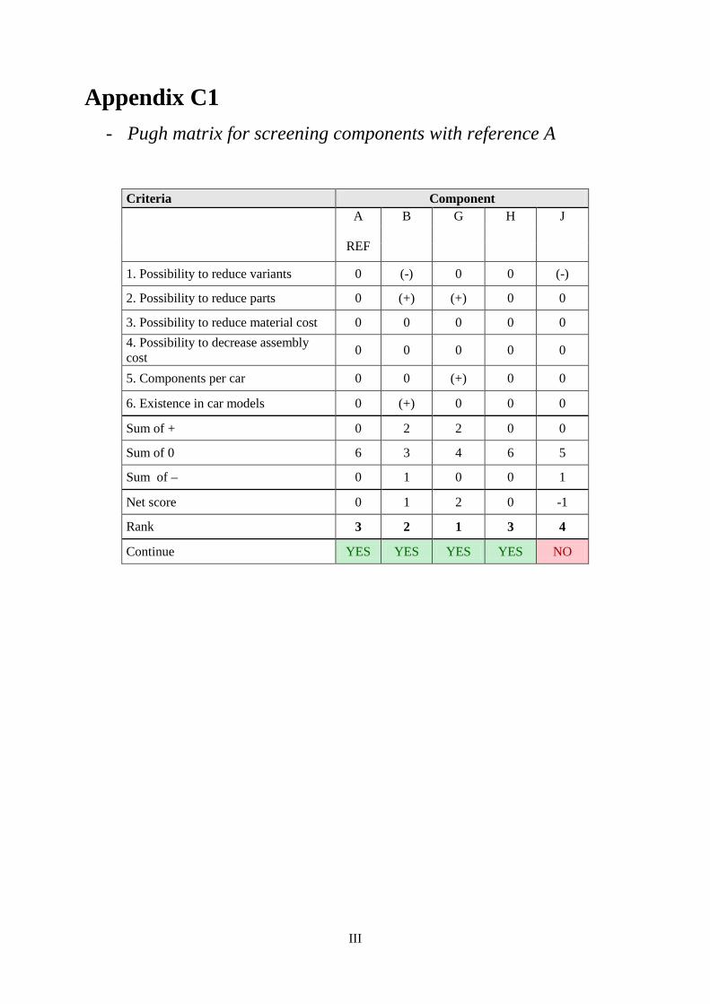
III
Appendix C1 - Pugh matrix for screening components with reference A
Criteria Component
A
REF
B G H J
1. Possibility to reduce variants 0 (-) 0 0 (-)
2. Possibility to reduce parts 0 (+) (+) 0 0
3. Possibility to reduce material cost 0 0 0 0 0 4. Possibility to decrease assembly cost 0 0 0 0 0
5. Components per car 0 0 (+) 0 0
6. Existence in car models 0 (+) 0 0 0
Sum of + 0 2 2 0 0
Sum of 0 6 3 4 6 5
Sum of – 0 1 0 0 1
Net score 0 1 2 0 -1
Rank 3 2 1 3 4
Continue YES YES YES YES NO

IV
Appendix C2 - Pugh matrix for screening components with reference G
Criteria Component
A B G
REF
H J
1. Possibility to reduce variants (+) 0 0 0 0
2. Possibility to reduce parts (-) 0 0 (-) (-)
3. Possibility to reduce material cost 0 0 0 0 0 4. Possibility to decrease assembly cost 0 0 0 0 0
5. Components per car (-) (-) 0 (-) (-)
6. Existence in car models 0 (+) 0 0 (-)
Sum of + 1 1 0 0 0
Sum of 0 3 4 7 4 0
Sum of – 3 2 0 2 3
Net score -2 -1 0 -2 -3
Rank 3 2 1 3 4
Continue YES YES YES YES NO

V
Appendix C3 Pugh matrix for screening components with reference H
Criteria Component
A B G
H
REF
J
1. Possibility to reduce variants 0 (-) (-) 0 (-)
2. Possibility to reduce parts (-) 0 (+) 0 0
3. Possibility to reduce material cost (+) (-) 0 0 0 4. Possibility to decrease assembly cost (-) 0 0 0 0
5. Components per car 0 0 (+) 0 0
6. Existence in car models 0 (+) 0 0 (-)
Sum of + 1 1 2 0 0
Sum of 0 4 3 3 6 4
Sum of – 2 2 1 0 2
Net score -1 -1 1 0 -2
Rank 3 3 1 2 4
Continue YES YES YES YES NO

VI
Appendix D1 - Competitor analysis, Component A – same class
Flat
tyre
wel
l, no
spe
cial
pla
ce to
pu
t sup
plie
rSh
aped
afte
r the
spa
re ti
re
No
tyre
wel
l, th
e ar
ea fo
r the
ar
ticle
s is
dire
ctly
und
er th
e bo
ot fl
oor
Fold
able
boo
t flo
or
Boo
tB
oot
VO
LK
SWA
GEN
TIG
UA
NFO
RD
MO
ND
EOSt
orag
eC
over
spa
re ti
reA
bate
sou
nd
Stor
age
Cov
er s
pare
tire
Aba
te s
ound
No
tyre
wel
lN
o ty
re w
ell
No
tyre
wel
l, th
e ar
ea fo
r the
ar
ticle
s is
dire
ctly
und
er th
e bo
ot
floor
Fold
able
boo
t flo
or
Boo
t
Key
obs
erva
tions
Dee
p ty
re w
ell,
spec
ial
area
s fo
r diff
eren
t arti
cles
Shap
ed a
fter s
pare
tire
Smal
l sto
rage
are
aR
oom
for s
ever
al a
rticl
esFl
at fo
rm
No
tyre
wel
l, th
e ar
ea fo
r the
sp
are
tire/
artic
les
is di
rect
ly u
nder
th
e bo
ot fl
oor
No
tyre
wel
l, th
e ar
ea fo
r th
e ar
ticle
s is
dire
ctly
un
der t
he b
oot f
loor
Boo
t flo
or is
dev
ided
in
two
parts
Tw
o st
orag
e ar
eas
No
room
for s
pare
tire
Phot
o
Plac
e in
car
Boo
tB
oot
Boo
tB
oot
No
tyre
wel
lN
o ty
re w
ell
No
of p
arts
11
No
tyre
wel
l
Stor
age
Cov
er s
pare
tire
Aba
te s
ound
Com
pone
nt: T
yre
wel
l
Func
tion
of th
e co
mpo
nent
Stor
age
Cov
er s
pare
tire
Aba
te s
ound
Stor
age
Cov
er s
pare
tire
Aba
te s
ound
Stor
age
Cov
er s
pare
tire
Aba
te s
ound
Stor
age
Cov
er s
pare
tire
Aba
te s
ound
Cla
ss: S
ame
clas
s
Car
mod
elV
OL
VO
XC
60B
MW
X3
MER
CED
ES G
LK
KIA
SO
REN
TOTO
YO
TA R
AV
4

VII
Appendix D2 - Competitor analysis, Component A – lower class
Dee
p ty
re w
ell
Not
pos
sible
to ta
ke it
out
Roo
m fo
r spa
re ti
re
No
tyre
wel
l, th
e sp
are
tyre
is d
irect
ly u
nder
the
boot
floo
r
Boo
tB
oot
VO
LK
SWA
GEN
GO
LF
FOR
D F
OC
US
Stor
age
Cov
er s
pare
tire
Stor
age
Cov
er s
pare
tire
10
Flat
tyre
wel
lH
andl
e in
tegr
ated
in
the
tyre
1
Key
obs
erva
tions
Dee
p ty
re w
ell,
spec
ial
plac
es to
put
arti
cles
Shap
ed a
fter t
he s
pare
ty
re/s
tyro
foam
Doe
s no
t hav
e a
tyre
wel
lA
reas
to s
tore
arti
cles
Flat
tyre
wel
lSh
aped
afte
r the
spa
re ty
reH
ande
l int
egra
ted
in th
e ty
re
wel
lC
lips
to k
eep
it in
pos
ition
Phot
o
1
Plac
e in
car
Boo
tB
oot
Boo
t
No
of p
arts
10
1
Boo
tB
oot
Stor
age
Cov
er s
pare
tire
Com
pone
nt: T
yre
wel
l
Func
tion
of th
e co
mpo
nent
Stor
age
Cov
er s
pare
tire
Stor
age
Cov
er s
pare
tire
Stor
age
Cov
er s
pare
tire
Stor
age
Cov
er s
pare
tire
Cla
ss: L
ower
cla
ss
Car
mod
elV
OL
VO
XC
60B
MW
1-S
ERIE
MER
CED
ES A
-CL
ASS
KIA
RIO
TOY
OTA
YA
RIS

VIII
Appendix D3 - Competitor analysis, Component B – same class
The
func
tion
of th
e ha
ndle
is to
be
abl
e to
ope
n th
e st
orga
re a
rea
unde
r the
floo
r.
Com
pone
nt: H
andl
e
Func
tion
of th
e co
mpo
nent
The
func
tion
of th
e ha
ndle
is to
be
abl
e to
ope
n th
e st
orga
re a
re
for t
he s
pare
tire
.
The
func
tion
of th
e ha
ndle
is to
be
abl
e to
ope
n th
e st
orga
re a
rea
unde
r the
floo
r.
The
func
tion
of th
e ha
ndle
is to
be
able
to
open
the
stor
gare
are
a un
der t
he fl
oor.
The
func
tion
of th
e ha
ndle
is to
be
abl
e to
ope
n th
e st
orga
re
area
und
er th
e flo
or.
Cla
ss: S
ame
clas
s
Car
mod
elV
OL
VO
XC
60B
MW
X3
MER
CED
ES G
LK
KIA
SO
REN
TOTO
YO
TA R
AV
4V
OL
SWA
GEN
TIG
UA
N
11
No
of fa
sten
ers
1 (th
e bl
ack
clip
s)H
ard
to e
stim
ate.
3
No
of p
arts
11
1
11,
with
a s
crew
Mat
eria
lPl
astic
Plas
ticPl
astic
and
pos
sible
met
al
The
wei
ght o
f thi
s co
mpo
nent
se
ems
sligh
tly li
ghte
r tha
n V
olvo
s so
lutio
n.
Plac
e in
car
In th
e bo
otIn
the
boot
In th
e bo
ot
Wei
ght
The
wei
ght o
f the
com
pone
nt
seem
s sim
ilar t
o V
olvo
s ha
ndle
.M
ight
be
heav
yer t
han
Vol
vos
hand
le.
The
wei
ght o
f thi
s com
pone
nt
seem
s slig
htly
ligh
ter t
han
Volv
os so
lutio
n.
In th
e bo
otIn
the
boot
Phot
o
Har
d to
est
imat
e
Plas
tic
In th
e bo
ot
Ver
y sim
ple
desig
n, ju
st a
stri
ng
to p
ull u
p th
e flo
or w
ith.
Key
obs
erva
tions
The
des
ign
of th
e co
mpo
nent
se
ems
to b
e co
mpl
ex. T
he b
oot
floor
and
the
hand
le a
re
deliv
ered
as
the
sam
e pa
rt to
the
fabr
ic.
The
han
dle
has
the
sam
e de
sign
on b
oth
sides
on
the
floor
. As
a us
er y
ou n
eed
to fl
ick
up th
e ha
ndle
to g
et a
grip
to p
ull t
he
floor
up
or d
own.
Seem
s lik
a a
quite
com
plex
han
dle.
The
ha
ndle
also
hav
e a
inte
garte
d fu
nctio
n fo
r ho
ldni
gn u
p th
e flo
or, a
stri
ng w
ith a
hoo
k on
.
Ver
y sim
ple
desig
n, ju
st a
stri
ng
to p
ull u
p th
e flo
or w
ith. T
he
floor
in th
e bo
ot w
ere
slip
so
two
of th
e ha
ndle
s w
ere
used
to
each
floo
r.
Som
e so
rt of
stri
ng.
Som
e so
rt of
stri
ng.
The
wei
ght o
f the
com
pone
nt s
eem
s sim
ilar t
o V
olvo
s ha
ndle
.
Sim
ple
desig
n
FOR
D M
ON
EDO
The
func
tion
of th
e ha
ndle
is
to b
e ab
le to
ope
n th
e st
orga
re a
rea
unde
r the
flo
or.
1 Har
d to
est
imat
e
Plas
tic
In th
e bo
ot
The
wei
ght o
f the
co
mpo
nent
see
ms
simila
r to
Vol
vos
hand
le.
Thi
s de
sign
is sim
ilar t
o th
e on
e B
MW
hav
e. Y
ou n
eed
to fl
ik th
e ha
ndle
to g
et a
gr
ip to
lift
up th
e flo
or.
The
func
tion
of th
e ha
ndle
is to
be
able
to
ope
n th
e st
orga
re a
rea
unde
r the
flo
or.
1

IX
Appendix D4 - Competitor analysis, Component B – lower class
In th
e bo
ot
Ligh
ter t
han
Vol
vos
hand
le.
Ver
y sim
ple
desig
n, ju
st a
stri
ng to
pul
l up
the
floor
with
. The
floo
r in
the
boot
wer
e sli
p so
two
of th
e ha
ndle
s w
ere
used
to e
ach
floor
.
The
func
tion
of th
e ha
ndle
is to
be
abl
e to
ope
n th
e st
orga
re a
rea
unde
r the
floo
r.
1 Har
d to
est
imat
e
In th
e bo
ot
The
pla
stic
of t
he h
andl
e is
scra
tche
d.
FOR
D F
OC
US
The
func
tion
of th
e ha
ndle
is to
be
able
to
open
the
stor
gare
are
a un
der t
he fl
oor.
1 Har
d to
est
imat
e
Ver
y sim
ple
desig
n, ju
st a
st
ring
to p
ull u
p th
e flo
or
with
. The
floo
r in
the
boot
w
ere
slip
so tw
o of
the
hand
les
wer
e us
ed to
eac
h flo
or.
Key
obs
erva
tions
The
des
ign
of th
e co
mpo
nent
se
ems
to b
e co
mpl
ex. T
he
boot
floo
r and
the
hand
le a
re
deliv
ered
as
the
sam
e pa
rt to
th
e fa
bric
.
The
han
dle
is in
tegr
ated
in th
e flo
or.
Seem
s lik
a a
quite
com
plex
han
dle.
The
han
dle
also
ha
ve a
inte
garte
d fu
nctio
n fo
r hol
dnig
n up
the
floor
, a
strin
g w
ith a
hoo
k on
.
The
han
dle
is sim
ply
cut o
ut fr
om th
e flo
or to
be
abl
e to
lift
the
floor
.
Plas
tic a
nd s
tring
Sam
e as
the
floor
The
wei
ght o
f the
com
pone
nt
seem
s sim
ilar t
o V
olvo
s ha
ndle
.
Phot
o
Mat
eria
lPl
astic
Sam
e as
the
floor
Plas
tic a
nd m
etal
Mig
ht b
e lig
hter
than
the
hand
le V
olvo
hav
e.
Plac
e in
car
In th
e bo
otIn
the
boot
In th
e bo
ot
Wei
ght
The
han
dle
is in
tegr
ated
in th
e flo
or.
Mig
ht b
e m
ore
heav
y th
an th
e ha
ndle
Vol
vo h
ave.
T
he h
andl
e is
inte
grat
ed in
the
floor
.
In th
e bo
otIn
the
boot
11
No
of fa
sten
ers
10
2
No
of p
arts
10
1
01T
he fu
nctio
n of
the
hand
le is
to
be
able
to o
pen
the
stor
gare
are
a un
der t
he fl
oor.
Com
pone
nt: H
andl
e
Func
tion
of th
e co
mpo
nent
The
func
tion
of th
e ha
ndle
is
to b
e ab
le to
ope
n th
e st
orga
re a
re fo
r the
spa
re ti
re.
The
func
tion
of th
e ha
ndle
is to
be
able
to
open
the
stor
gare
are
a un
der t
he fl
oor.
The
func
tion
of th
e ha
ndle
is to
be
able
to o
pen
the
stor
gare
are
a un
der t
he fl
oor.
The
func
tion
of th
e ha
ndle
is to
be
able
to
open
the
stor
gare
are
a un
der t
he fl
oor.
Cla
ss: L
ower
cla
ss
Car
mod
elV
OL
VO
XC
60B
MW
1-S
ERIE
MER
CED
ES A
-CL
ASS
KIA
RIO
TOY
OTA
YA
RIS
VO
LK
SWA
GEN
GO
LF

X
Appendix D5 - Competitor analysis, Component G – same class
Prot
ect f
rom
sun
Mirr
or y
ours
elf
Com
pone
nt: S
un v
isor
Func
tion
of th
e co
mpo
nent
Prot
ect f
rom
sun
Mirr
or y
ours
elf
Prot
ect f
rom
sun
Mirr
or y
ours
elf
Prot
ect f
rom
sun
Mirr
or y
ours
elf
Prot
ect f
rom
sun
Mirr
or y
ours
elf
Cla
ss: S
ame
clas
s
Car
mod
elV
OL
VO
XC
60B
MW
X3
MER
CED
ES G
LK
KIA
SO
REN
TOTO
YO
TA R
AV
4
22
No
of fa
sten
ers
2 pa
r par
t2
per p
art
2 pe
r par
t
No
of p
arts
22
2
2 pe
r par
t2
per p
art
Cei
ling
Cei
ling
Phot
o
Cei
ling
Plac
e in
car
Cei
ling
Cei
ling
Key
obs
erva
tions
Ligh
t in
sun
viso
rA
utom
atic
ligh
tFo
ldab
le li
d
Ligh
t in
ceili
ngA
utom
atic
ligh
tSl
idin
g lid
Ligh
t in
ceili
ngA
utom
atic
ligh
tFo
ldab
le li
d
Ligh
t in
ceili
ngM
anua
l lig
ht w
ith b
utto
nSl
idin
g lid
Ligh
t in
ceili
ngA
utom
atic
ligh
tSl
idin
g lid
Ligh
t in
sun
viso
rA
utom
atic
ligh
tFo
ldab
le li
d
2 pe
r par
t2
per p
art
Cei
ling
Cei
ling
VO
LK
SWA
GEN
TIG
UA
NFO
RD
MO
ND
EOPr
otec
t fro
m s
unM
irror
you
rsel
fPr
otec
t fro
m s
unM
irror
you
rsel
f
22
Ligh
t in
ceili
ngA
utom
atic
ligh
tSl
idin
g lid

XI
Appendix D6 - Competitor analysis, Component G – lower class
2 pe
r par
t
Cei
ling
2 2 pe
r par
t
No
light
Fold
able
lid
VO
LK
SWA
GEN
GO
LF
FOR
D F
OC
US
2 pe
r par
t2
per p
art
Prot
ect f
rom
sun
Mirr
or y
ours
elf
Prot
ect f
rom
sun
Mirr
or y
ours
elf
KIA
RIO
TOY
OTA
YA
RIS
2
Ligh
t in
ceili
ngA
utom
atic
ligh
tSl
idin
g lid
Ligh
t in
sun
viso
rA
utom
atic
ligh
tFo
ldab
le li
d
Cei
ling
Prot
ect f
rom
sun
Mirr
or y
ours
elf
2
Key
obs
erva
tions
Ligh
t in
sun
viso
rA
utom
atic
ligh
tFo
ldab
le li
d
Ligh
t in
ceili
ngA
utom
atic
ligh
tSl
idin
g lid
Ligh
t in
ceili
ngA
utom
atic
ligh
tFo
ldab
le li
d
No
light
Slid
ing
lid
Cei
ling
Phot
o
Plac
e in
car
Cei
ling
Cei
ling
Cei
ling
Cei
ling
No
of p
arts
22
22
No
of fa
sten
ers
2 pe
r par
t2
per p
art
2 pe
r par
t
Com
pone
nt: S
un v
isor
Func
tion
of th
e co
mpo
nent
Prot
ect f
rom
sun
Mirr
or y
ours
elf
Prot
ect f
rom
sun
Mirr
or y
ours
elf
Prot
ect f
rom
sun
Mirr
or y
ours
elf
Cla
ss: L
ower
cla
ss
Car
mod
elV
OL
VO
XC
60B
MW
1-S
ERIE
MER
CED
ES A
-CL
ASS
Prot
ect f
rom
sun
Mirr
or y
ours
elf

XII
Appendix E1 - Outcome from workshop with Component A
Concept A-I This concept is about remove the bowl and move the articles that today is stored in the bowl to either the storage part under the bowl or in another place in the boot. The warning triangle is one of the articles that is stored in the bowl, it can be hard to get this device out of the boot if the luggage is filled with stuff if the warning triangle is needed.
Concept A-II This concept is about finding common points for different car model to be able to eliminate variants of the bowl. One solution can be to have one bowl for if the car has a spare tire and one bowl for the car models without spare tire. Maybe a flexible material can be used.
Concept A-III To prevent that the articles are moving around in the bowl the articles can have burdock to be able to mount them to the bowl. Another option is to put the articles under the boot floor with burdock and remove the bowl.
Concept A-IV To customize the bowl movable walls can be made with burdock so that the customer can decide where to put them. This also prevent articled to move around if the area fits the article perfectly. The bowl

XIII
would then be as straight as possible. The bowl can be made in burdock or just some parts of burdock can be attached to be able to mount the walls.
Concept A-V Cargo net can be used to hold the articles in the correct place, this can be used in the bowl, under the boot floor or in the boot area. The cargo net would have to have smaller stitches so that smaller articles stay in place as well. With this solution, no partition in the bowl would be needed.
Concept A-VI Different storage areas with lids on. The storage areas should be perfectly measured to just fit the articles placed in the boxes.
Concept A-VII Instead of having boxes for storage a flexible material that allows the articles to sink down can be used. This material could be integrated in the bowl and the material can for example be similar to a cargo net but with smaller stitches.

XIV
Concept A-VIII Have storage areas in the sides of the boot that perfectly fits the articles. The bowl could then be removed.
Concept A-X Remove the needle felt from the bowl, does it need to have that nice finished since the boot floor covers the bowl anyway? The cost can be reduced since the material can be removed and they do not need to laminate the two materials together anymore.

XV
Appendix E2 - Outcome from workshop with Component B
Concept B-I Integrate the handle into the boot floor. A small bowl could be pressured at the same time when the boot floor is made and a hole to fit the finger could be cut out. The component today can then be removed. A plastic piece could be used to cover the hole if necessary.
Concept B-II For those cars with extra storage space with a small handle for opening that area can a similar handle be used to open the boot floor.

XVI
Concept B-III This is an idea to remove the handle completely to remove that article. The handle can be integrated in the boot floor if a piece of the boot floor is cut away.
Concept B-IV This idea is about to the remove the handle that is used today and instead use some sort of string. This can be attached to the boot floor with a screw on the back side. The string can be pulled through the floor through a slit. The handle is flat when it is not used and can be pulled up when wanted. The handle can either be mounted in two anchor point or in one.
Concept B-V This concept is about remove the handle and use the hole that the handles is mounted in today. A piece of stretchable fabric can be mounded on the underside of the boot floor to prevent that stuff falls through the hole. The fabric can be glued or stamped to the boot floor to stay attached. The fabric also make sure

XVII
that the bowl cannot be seen through the hole. The needle felt from the bowl can nicely be rapped round the hold to avoid ugly edges.
Concept B-VI Keep the almost the same shape of the handle but instead of having the black stick, a push pin can be used. The push pin is placed in the handle and works in the same way as a lock that snaps to the bottom side of the boot floor. The lock is integrated in the handle.

XVIII
Concept B-VII The handle can be redesigned to just on part instead of two. This can be done through using extruded aluminum which is a quite soft material to give the possibility to snap it in the correct place. Maybe this design also can be done in plastic.
Concept B-VIII Hinges can be used instead of the handle that is used today. Keep the hole and use a hinge in the middle of the hole. This also covers the sight of the bowl.
Concept B-IX In some car models parallel loading handrails are available. For those car models can the rail be the handle.

XIX
Concept B-X This concept is about removing the old handle and instead use a rod with a knot on the underside of the boot floor to be able to lift the floor. The floor needs to have a gouging so that the handle can fit to be at the same level as the floor. The material of the string can be of for example rubber or leather.
Concept B-XI Remove the handle and use a spring instead. The floor will pop up then the floor pushes down to be able to open it.
Concept B-XII Remove today´s handle and just cut two holes out that can be used as a handle. The edges can be in the same material as the boot floor. To avoid to see the bowl a piece of soft fabric can be used on the underside of the boot floor. Maybe only one hole is needed.

XX
Concept B-XIII This concept is about having a manual or en electrical button to open the boot floor. The manual button should work as a pop up button to be able to lift up the floor. The electrical button should lift up the whole floor.
Concept B-XIV The old handle can be removed and a stick can be mounded over the hole. This would give the possibility to lift the floor in this handle.

XXI
Concept B-XV This handle works in the same way as a hinge. It is mounted in the side of the boot floor and can then be lifted up to work as a handle.

XXII
Appendix E3 - Outcome from workshop with Component G
Concept G-I Remove the light and the mirror on either over the driver´s seat or over both seats in the V40 cars. This could be possible since this car model is not one of the premium car models.
Concept G-II Make to whole sun visor thinner or smaller to reduce material.
Concept G-III Replace the silencer with small pieces of felt or rubber.
Concept G-IV A sun visors in the corner to prevent to get the sun in the eyes. The sun visor today is folded down and the lid for the mirror covers the whole sun visor and makes it possible to fold it out with 90 degrees to cover the sun that potential can some from that angle. The mirror is placed in the same way as today’s sun visor but the light is placed in the ceiling. Something needs to cover the mirror when the lid is open.

XXIII
Concept G-V Dependent on how the sun visor looks inside today, the sun visor could be made in two parts. One of the parts could have ribs to stabilize the sun visor. Clips could be used to assemble the two parts together.
Concept G-VI To reduce the electricity from the sun visor the light can be placed in the ceiling instead. The electricity that already exists in the ceiling can be used.

XXIV
Concept G-VII A solution where the design of the sun visor is changed. Reduction of material can be made due to the design and since the light is place closer the overhead console, the cables can be shorter. The light can be a LED light with a battery.
Concept G-VIII Change the design of the lid to a sliding lid. The lid can probably be thinner than the lid used today. It is important to think about that the lid need to fit in the sun visor when the mirror is visible.
Concept G-IX The mirror is placed in the sun visor in the same way as todays sun visor, the light is placed in the ceiling. The lid is design in such way so it is folded down to not cover the light. An important aspect here is to make sure that the lid stays in its upper position when the sun visor is folded down.

XXV
Concept G-X The mirror and the light is placed in the lid that is folded down to make the mirror visible. The light can also be placed in the ceiling.
Concept G-XI A design for the lid, the lid can be split in two.

XXVI
Appendix E4 - Outcome from workshop with Component H
Concept H-I This concept is about removing the clips and replace them with a slit. The aborbents can then be mounted through treetops in the body.
Concept H-II Remove the clips, burdock can be mounted in the body of the car and also on the absorbents to be able to mount them. Might be hard to position the absorbent correct.
Concept H-III Integrate the absorbent in the inner panel.
Concept H-IV Maybe there is possible to use a material with some sort of glue that is flexible so it easily forms after the body.
Concept H-V Combine the absorbents for the V60 and for the V60 Bi Fuel, this would be good since a variant can be reduced.
Concept H-VI Combine the absorbent for the V60 and for the V60 Bi Fuel, use a flexible material so the same absorbent can be used in both car models.
Concept H-VII Instead of having the clips a hook can be used instead to keep the absorbent in the right position. The hook can be mounted on to the absorbent.

XXVII
Concept H-VIII Reduce one clip, maybe it is enough with one clip on the top of the absorbent.

XXVIII
Appendix F1 - Weighted Pugh matrices for selecting component
Criteria Weight Component
A
REF
B G H
1. Possibility to reduce variants 3 0 (-) (-) 0
2. Possibility to reduce parts 3 0 (+) (+) (+)
3. Possibility to reduce material cost 3 0 (-) 0 0 4. Possibility to decrease assembly cost 3 0 (+) (+) (+)
5. Components per car 4 0 0 (+) 0
6. Existence in car models 4 0 (+) (+) 0
Sum of + 0 3 4 2
Sum of 0 6 1 1 4
Sum of – 0 2 1 0
Weighted sum of + 0 10 14 6
Weighted sum of - 0 6 3 0
Net score 0 4 11 6
Rank 4 3 1 2
Continue NO NO YES NO

XXIX
Appendix F2 - Weighted Pugh matrices for selecting component
Criteria Weight Component
A B
REF
G H
1. Possibility to reduce variants 3 (+) 0 0 (+)
2. Possibility to reduce parts 3 (-) 0 (+) 0
3. Possibility to reduce material cost 3 (+) 0 (+) (+) 4. Possibility to decrease assembly cost 3 (-) 0 0 0
5. Components per car 4 0 0 (+) 0
6. Existence in car models 4 0 0 0 (-)
Sum of + 2 0 3 2
Sum of 0 2 6 3 3
Sum of – 2 0 0 1
Weighted sum of + 6 0 10 6
Weighted sum of - 6 0 0 4
Net score 0 0 10 2
Rank 3 3 1 2
Continue NO NO YES NO

XXX
Appendix F3 - Weighted Pugh matrices for selecting component
Criteria Weight Component
A B G
REF
H
1. Possibility to reduce variants 3 (+) 0 0 0
2. Possibility to reduce parts 3 (-) (-) 0 (-)
3. Possibility to reduce material cost 3 0 (-) 0 0 4. Possibility to decrease assembly cost 3 (-) 0 0 0
5. Components per car 4 (-) (-) 0 (-)
6. Existence in car models 4 (-) (+) 0 0
Sum of + 1 1 0 0
Sum of 0 0 2 6 4
Sum of – 4 3 0 2
Weighted sum of + 3 4 0 0
Weighted sum of - 14 10 0 7
Net score -11 -6 0 -7
Rank 4 2 1 3
Continue NO NO YES NO

XXXI
Appendix G1 - Component structure

XXXII
Appendix G2 - Component structure

XXXIII
Appendix H - Function analysis for sun visor
Shade sun
Reflect image
Protect from light reflections
Handle automatic light
Turn light on Turn light off
Inform about airbag Cushion sounds
Protect from light from
different angles
Rotate
Stay in desired position

XXXIV
Appendix I - Questionnaire
1. How often do you use the mirror in the sun visor in your car?
1. Very often (every day) 2. Sometimes (once a week) 3. Rarely (once a month) 4. Never
2. If you have a parking ticket holder in your sun visor how often do you use it? 1. Very often (every day) 2. Sometimes (once a week) 3. Rarely (once a month) 4. Never
3. If you DO NOT have a parking ticket holder or similar in the sun visor, would you benefit from one?
1. Yes 2. No 3. I don´t know
4. What do you think about that the sun visor is in plastic when the ceiling is in fabric? 1. Ok 2. Not ok 3. I don´t know
Figure 1, Result from questionnaire
5
0 1
12
7
0
23
5
17
9
4
12
1
16
Q U E S T I O N 1 Q U E S T I O N 2 Q U E S T I O N 3 Q U E S T I O N 4
QUESTIONNAIREAlternativ 1 Alternativ 2 Alternativ 3 Alternativ 4

XXXV
Appendix J - Competitor analysis with sun visor for XC90
Picture
Assembles as two parts
Key observations The sun visor has two silencer of rubber The ceiling is in fabricDifferent shape for ringht and left sun visor
Different shape for the left and right sun visor
Different shape for the left and the right sun visor
Assembled Assembled as two parts Assembled as two parts Assembled as two parts
Solution for covering the mirror
Foldable lid Foldable lid Sliding lid Sliding lid
Fabric
Postion of light Sun visor Ceiling Ceiling Around the mirror
Parking ticket holder Yes Yes Yes Yes
1
Automatic/Manual light Automatic Automatic Automatic Automatic
Surface material Fabric Vinyl Vinyl
Number of lights 1 1 1
Function of the component
Protect from sunMirror yourselfCard holder
Protect from sunMirror yourselfCard holder
Protect from sunMirror yourselfCard holder
Protect from sunMirror yourselfCard holder
Sun visor
Class: Same class as XC90
Car model Volvo XC90 Mercedes GL BMW X6 Audi Q7

XXXVI
Appendix K - Concept structure matrix for all ideas
Part 1 2 3 4 5 6 7
A. Surface Material
Cheaper foam
Thinner foam
No foam, only fabric
Remove gauze
Vinyl instead of fabric
Remove adhesive
Reduce amount of adhesive
B. Light
No light Bulb Move to roof lining
Changeable light
Light above mirror
Light on both
sides of mirror
C. Electronics
Solar cell
Sensor in car
Mechanical switch
Manual switch
Sensor for light/darkness
Reduce material
D. Padding Reduce material
Lower density
E. Mirror
Cheaper material
Smaller mirror
Remove label from
the backside
F. Frame
Remove ticket holder
Reduce material
Remove frame
G. Glue Reduce Cheaper
H. Skeleton
Reduce material
Same for right and left
Reduce amount of
clips
Cheaper material
I. Cover for light Reduce material
Cheaper material
J. Silencer Remove
K. Lid Remove
lines Remove
lid Sliding lid
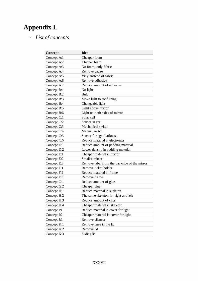
XXXVII
Appendix L - List of concepts
Concept IdeaConcept A:1 Cheaper foamConcept A:2 Thinner foamConcept A:3 No foam, only fabricConcept A:4 Remove gauzeConcept A:5 Vinyl instead of fabricConcept A:6 Remove adhesive Concept A:7 Reduce amount of adhesiveConcept B:1 No lightConcept B:2 BulbConcept B:3 Move light to roof liningConcept B:4 Changeable lightConcept B:5 Light above mirrorConcept B:6 Light on both sides of mirrorConcept C:1 Solar cellConcept C:2 Sensor in carConcept C:3 Mechanical switchConcept C:4 Manual switchConcept C:5 Sensor for light/darknessConcept C:6 Reduce material in electronicsConcept D:1 Reduce amount of padding materialConcept D:2 Lower density in padding materialConcept E:1 Cheaper material in mirrorConcept E:2 Smaller mirrorConcept E:3 Remove label from the backside of the mirrorConcept F:1 Remove ticket holderConcept F:2 Reduce material in frameConcept F:3 Remove frameConcept G:1 Reduce amount of glueConcept G:2 Cheaper glueConcept H:1 Reduce material in skeletonConcept H:2 The same skeleton for right and leftConcept H:3 Reduce amount of clipsConcept H:4 Cheaper material in skeletonConcept I:1 Reduce material in cover for lightConcept I:2 Cheaper material in cover for lightConcept J:1 Remove silencerConcept K:1 Remove lines in the lidConcept K:2 Remove lidConcept K:3 Sliding lid

XXXVIII
Appendix M - Elimination matrix by Pahl & Beitz
DecisionA:1 (+) (-) (+) (+) (+) (-) (-) (-)A:2 (+) (-) (+) (+) (-) (+) (-) (-)A:3 (+) (-) (+) (+) (+) (+) (-) (-)A:4 (+) (-) (+) (+) (-) (+) (-) (-)A:5 (+) (+) (+) (-) (+) (+) (-) (-)A:6 (+) (-) (+) (-) (+) (+) (-) (-)A:7 (+) (-) (+) (-) (-) (+) (-) (-)B:1 (+) (+) (+) (-) (+) (+) (-) Decreased customer value (-)B:2 (-) (-) (+) (+) (+) (+) (-) (-)B:3 (-) (-) (+) (+) (-) (+) (-) (-)B:4 (-) (-) (+) (+) (-) (+) (-) (-)B:5 (-) (-) (+) (+) (+) (+) (-) (-)B:6 (+) (-) (+) (+) (+) (+) (-) (-)C:1 (+) (+) (+) (+) (+) (+) (-) (-)C:2 (-) (-) (+) (+) (?) (-) (-) (-)C:3 (-) (-) (-) (+) (-) (-) (-) (-)C:4 (+) (+) (+) (-) (+) (+) (-) (-)C:5 (-) (-) (+) (+) (+) (-) (-) (-)C:6 (-) (+) (+) (+) (+) (+) (-) (-)D:1 (-) (+) (?) (+) (?) (-) (-) (-)D:2 (+) (-) (+) (+) (+) (+) (+) (-)E:1 (+) (-) (+) (+) (+) (+) (+) (-)E:2 (+) (-) (+) (-) (+) (+) (-) (-)E:3 (+) (-) (-) (+) (+) (-) (-) (-)F:1 (+) (-) (+) (+) (+) (+) (-) (-)F:2 (-) (-) (+) (+) (-) (+) (-) (-)F:3 (+) (-) (+) (+) (+) (+) (-) (-)G:1 (+) (-) (+) (+) (+) (-) (+) (-)G:2 (+) (-) (+) (+) (+) (?) (+) (-)H:1 (+) (-) (+) (+) (-) (+) (-) (-)H:2 (+) (+) (+) (+) (+) (+) (-) (-)H:3 (+) (-) (+) (+) (+) (+) (-) (-)H:4 (+) (+) (+) (+) (+) (-) (-) (-)I:1 (-) (-) (+) (+) (?) (-) (-) (-)I:2 (+) (-) (+) (+) (+) (-) (+) (-)J:1 (+) (-) (-) (+) (+) (+) (+) (-)K:1 (+) (-) (+) (-) (+) (+) (-) Low potential for cost reduction (-)K:2 (+) (+) (-) (-) (+) (+) (-) (-)K:3 (+) (+) (+) (+) (+) (+) (-) (-)
Too complicatedNot enough information
More expensive
Comment
(?) More information needed(-) No(+) YesDecision(?) More information needed(-) No(+) YesElimination criteria
Suff
icie
nt in
fora
mtio
n
Con
cept
Cle
ar d
escr
iptio
n of
idea
Poss
ibili
ty to
redu
ce c
osts
Fulfi
l VC
C re
quire
men
ts
Mai
ntai
n cu
stom
er v
alue
Rea
lizab
le
Impl
emen
tabl
e in
nea
r fut
ure
Related Documents