Revision date: 03.08.17 ©2017 GrowSpan All Rights Reserved. Reproduction is prohibited without permission. Series 500 Greenhouse Kit w/Blackout System, Ventilation & Evaporative Cooling GB30PVRED 30' Wide Series 500 Greenhouse Framing Kit: All Standard Lengths. RED - Main Frame

Welcome message from author
This document is posted to help you gain knowledge. Please leave a comment to let me know what you think about it! Share it to your friends and learn new things together.
Transcript

1Revision date: 03.08.17
©2017 GrowSpanAll Rights Reserved. Reproduction is prohibited without permission.
Series 500 Greenhouse Kit w/Blackout System, Ventilation & Evaporative Cooling
GB30PVRED 30' Wide Series 500 Greenhouse Framing Kit:
All Standard Lengths.
RED - Main Frame

2 Revision date: 03.08.17
4 GREEN - ROOF CLADDING (Film, Inflation Kits and Termination)
Color Coding
READ THIS BEFORE YOU BEGINPurchased greenhouse and all accessories & systems require a specific installation sequence. All components have been separated into different categories based on common grouping and/or the chronology of installation. Each category has been color coded. All parts within any given color category will be labeled accordingly, and each color category will have its own respective instruction manual.
The following illustrates a highly recommended order in which all components should be installed.
IMPORTANT: There are some procedures that can occur simultaneously, depending on available assistants and equipment, but there are some procedures that MUST be done in chronological order. Before you begin, review below step recommendation and all technical documents to better understand overall building kit design.
Near the beginning of each color-coded instruction guide, you will find information to lead you through the installation and assembly steps. This information identifies at what point during the assembly the respective components are installed or attached to the main building frame.
Since we cannot anticipate changes made by the customer/contractor, all instructions assume the use of accessories purchased from us to be used on the building the accessory was designed for. Each instruction guide presents the basic steps to install the color-coded components.
When in doubt, consult the services of a qualified contractor experienced with the assembly of similar structures.
1 RED - MAIN FRAME (Rafters, Purlins, Chord Support and Cabling)
ORANGE - END WALL FRAMING (Columns, Cross Beams and Door Framing)
BLUE - END WALL CLADDING (Polycarbonate, Termination and Flashing)
YELLOW - EVAPORATIVE COOLING (Framing, Cooling Pads and Plumbing)
BROWN - END WALL VENT (Framing, Motor and Drive Shaft)
WHITE - VENTILATION (Exhaust Fans, Ceiling Fans and Light Traps)
PURPLE - STATIC BLACKOUT (Monofilament, Fixation and Sealing)
BLACK - MOVABLE BLACKOUT (Fabric, Leading Edge, Motor and Drive Shaft)
GRAY - BLACKOUT SIDE POCKET (Framing and Polycarbonate)
2
3
6
7
8
9
10
11
PINK - AIR DISTRIBUTION (Fan, Vent Tube and Shutter)5
3Revision date: 03.08.17
Color Coding
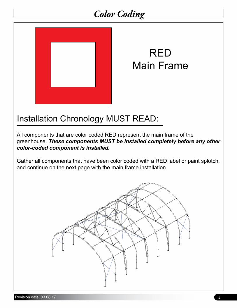
All components that are color coded RED represent the main frame of the greenhouse. These components MUST be installed completely before any other color-coded component is installed.
Gather all components that have been color coded with a RED label or paint splotch, and continue on the next page with the main frame installation.
RED Main Frame
Installation Chronology MUST READ:
4 Revision date: 03.08.17
WIND AND SNOW LOAD
Many GrowSpan™shelters and greenhouses can be designed to meet wind and snow loading in your area. Please consult with your account manager if needed for additional information.
SITE
After choosing a location, proper preparation of the site is essential. Follow the information below.
• A level site is required. The site must be level to properly and safely erect and anchor the structure.
• Drainage: Water draining off the structure and from areas surrounding the site should drain away from the site to prevent damage to the site, structure, and contents of the structure.
WARNING: Those assembling this structure are responsible for designing and furnishing all temporary bracing, shoring and support needed during assembly. For safety reasons, those who are not familiar with recognized construction methods and techniques must seek the help of a qualified contractor.
Important Information
READ THIS DOCUMENT BEFORE YOU BEGIN
Thank you for purchasing a Series 500 greenhouse kit with a black-out system, ventilation & evaporative cooling. When properly assembled and maintained, this product will provide years of reliable service. These instructions include helpful hints and important information needed to safely assemble and properly maintain the structure. Please read these instructions before you begin.
If you have any questions during the assembly, please contact customer service for assistance.
SAFETY PRECAUTIONS
• Wear eye protection.
• Wear head protection.
• Wear gloves when handling metal parts.
• Use a portable GFCI (Ground Fault Circuit Interrupter) when working with power tools and cords.
• Do not climb on the frame during or after construction.
• Do not occupy the structure during high winds, tornadoes, or hurricanes.
• Provide adequate ventilation if the structure is enclosed.
• Do not store hazardous materials in the structure.
• Provide proper ingress and egress to prevent entrapment.
• NEVER hang items from the system components!
LOCATION
Choosing the proper location is an important step before you begin. The following suggestions and precautions will help determine whether your selected location is best.
• Always check local building codes before you begin and follow codes as instructed.
• Never erect the structure under power lines.
• Identify whether underground cables and pipes are present before preparing the site, setting ground posts or anchoring the structure.
• Location should be away from structures that could cause snow to drift on or around the building.
• Do not position the structure where large loads such as snow and ice, large tree branches, or other overhead obstacles could fall.
SETTING THE GROUND POSTS/BASE PLATES
The frame assembly of this building requires the setting of all ground post in concrete, or base plates on concrete. Review the layout diagrams for additional details.
Enlist the services of a professional and competent contractor to prepare the site and set the ground posts.
Failing to secure ground posts or base plates in concrete as required may result in damage to the building, building contents, and surrounding property.

5Revision date: 03.08.17
Important Information
REQUIRED TOOLS
The following list identifies the main tools needed to assemble the greenhouse kit. Additional tools and supports may be needed depending on the structure, system, location, conditions and application.
• Tape measure or measuring device and marker to mark locations on the pipes and rafters.
• Variable speed drills and impact drivers. (Cordless with extra batteries works best.)
• Metal-cutting saws or tools to cut pipe and aluminum.
• Drill bit set
• Wrenches and impact socket set, hammer, and gloves.
• Adjustable pliers and self-locking pliers.
• 4mm Hex wrench to tighten set screws
• Level 6' (or longer) preferred
• String line (or chalk line)
• Square to check vent frame during assembly
• Scissors or utility knife
• Ladders, work platforms, and other machinery for lifting designed to work safely at the height of the building.
• Safety equipment to protect head, eyes, hands and feet.
UNPACK AND IDENTIFY PARTS
The following steps will ensure that you have all the necessary parts before you begin to assemble the shelter frame.
1. Unpack the contents of the shipment and place where you can easily inventory the parts. Refer to the Bill of Materials/Spec Sheets.
2. Verify that all parts listed on the Bill of Materials/Spec Sheets are present. If anything is missing or you have questions, consult the Pictorial Parts Guide and all diagrams for clarification, or contact Customer Service. NOTE: Do not open plastic bags containing smaller parts such as fasteners or washers at this time. Simply verify quantity.
ANCHORING THE BUILDING
The anchoring methods shown in this manual for buildings with base plates or buildings with ground posts are temporary in nature. For the recommended permanent anchoring methods, consult the MUST READ documents that also shipped with your building. The diagrams presented in that guide show anchoring methods designed to meet typical loads and forces. Consult that document and read its contents before you begin construction.
ASSEMBLY
Following the instructions as presented will help ensure proper assembly. Failing to follow these steps may result in an improperly assembled and anchored structure. IMPORTANT: There are some procedures that can occur simultaneously, depending on available assistants and equipment, but there are some procedures that MUST be done in chronological order. Before you begin, review all technical documents to better understand overall building design.
The steps outlining the basic frame assembly are as follows:
1. Verify that all parts are included in the shipment. Notify Customer Service for questions or concerns.
2. Read this guide and all additional documentation included with the shipment before you begin.
3. Gather the tools, bracing, ladders, lifts, and assistants needed to assemble the structure.
4. Check the weather before you install the roof cover and any end panels (if equipped). Do not install covers or panels on a windy or stormy day.
5. Re-evaluate the location and site based on the information and precautions presented in the documentation included with the shipment.
6. Prepare the site (if applicable) and set the ground posts in concrete. If building includes end framing, review those instructions and drawings for additional end framing requirements.
7. Assemble rafter components and rafter support components.
8. Assemble main building frame (rafters, cabling, purlins etc).
9. If used, attach baseboards (customer-supplied).

6 Revision date: 03.08.17
Parts Identification
102546 Cross Connector
QH1070Pipe Strap
103856Band Clamp
AS2167 Anchor Shackle
104189 Turnbuckle
FA4482BTek Screw
100441Magnetic Nut Setter
The following graphics will help identify the basic parts of the frame. (Some parts are not shown.)
115249End Rafter
(Base Plates Only)
115250Mid Rafter
(Base Plates Only)
108503 Cable Bracket
PGBRKAAS01 Bracket
106735Square Band
Clamp

7Revision date: 03.08.17
Overview
Drawing may show a model of a different length. Refer to Technical Documents located near the back of this guide for on-center measurements and post layout.
OVERVIEW
This section describes assembling your building frame. See illustration below to identify main parts.
1. Prepare site and set the ground posts/base plates in or on concrete.
2. Locate the required parts for each assembly procedure.
3. Assemble the rafters and main frame.
Ground Level
End Rafter
Interior Rafter
Webbing Strut
Ridge Purlin
Side Purlin
Rafter Support Chord
VerticalHeader
Cable
Ground Post
On-center
GrowSpan™ Series 500
Greenhouse Frame

8 Revision date: 03.08.17
Prepare and Square the Building SitePREPARE THE BUILDING SITE
A level site is required to accurately and safely construct the building. Consult the services of a qualified contractor to properly grade and prepare the site.
Site should slope away from the building for proper water drainage.
After the site is prepared, mark the location of the frame corners to square the frame position. Taking these steps before assembling the shelter saves time and ensures that the structure is square and positioned as desired.
The following procedures are suggested methods.Their use depends on the size of the shelter, shelter application, base plates (if applicable), and the method used to anchor the shelter.
When in doubt, consult the services of a qualified contractor experienced with the construction of similar structures.
Ground Posts
If the frame includes ground posts, set all ground posts as described within this manual. Width of the shelter is measured from the center of one ground post to the center of the remaining ground post. Length is also measured center-to-center.
If the frame includes ground posts, continue with the Set Ground Post section. Review the layout diagrams for additional details.
Enlist the services of a professional and competent contractor to prepare the site and set the ground posts.
Failing to secure ground posts in concrete as required may result in damage to the building, building contents, and surrounding property.
Rafter Base Plates
If your frame includes base plates, prepare the site and anchor the plates to the site before assembling the frame. Read the following information and use the diagram to layout the position of your building. Once the string lines are set to mark the location, continue with the Base Plates section.
Unless you are securing plates to concrete piers, do not dig holes if your building is equipped with rafter base plates! Read the information on the Base Plate Installation (if equipped) page for additional details.
SQUARE THE SITE: GENERAL STEPS
1. Identify a corner where a building rafter will be positioned, drive in a stake, and string a line the exact width of the building and stake in place. (Width of the rafter is measured from center-to-center of the rafter legs.)
2. After the first corner stake is in place, string a line the width of the building (center-to-center) and drive the second corner stake into the ground.
3. String a line at least as long as the building 90° from the line between the first and second stakes.
NOTE: A transit can be used to ensure an accurate 90° angle, or the 3-4-5 rule can be used. Refer to diagram. Using multiples of 3-4-5 such as 6-8-10 or 12-16-20 helps to maintain an accurate 90° angle.
4. After squaring the position of the building, measure the length and drive the third corner stake.
5. Repeat the same step for the last corner stake. NOTE: The distance measured diagonally between corner stakes must be equal for the building to be square.
6. If purchased greenhouse includes ground posts, continue with the "Set Ground Posts" section on the following page. If purchased greenhouse includes base plates, skip to the "Base Plate Installation" pages. NOTE: If attaching base plates to a slab, consult and follow local and regional building codes for slab requirements.
9Revision date: 03.08.17
Set Ground Posts
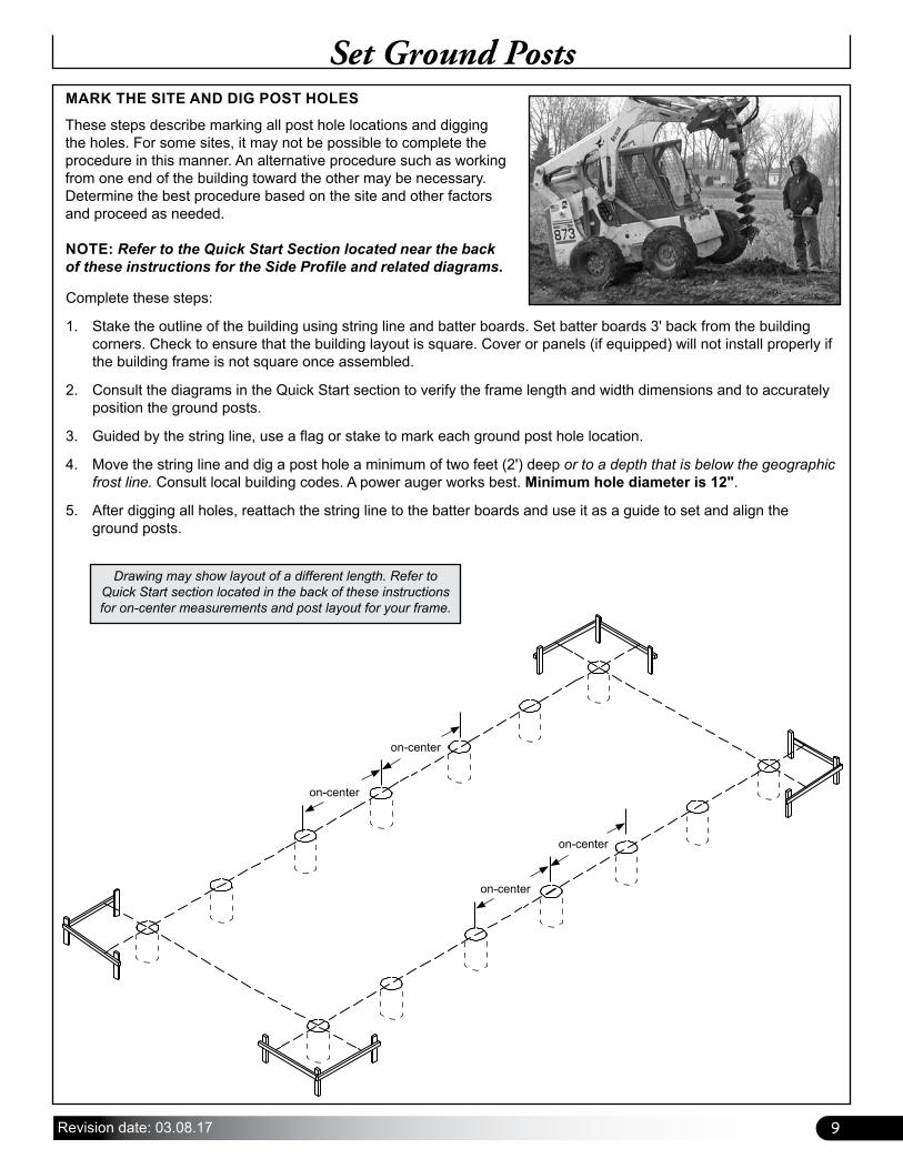
Drawing may show layout of a different length. Refer to Quick Start section located in the back of these instructions for on-center measurements and post layout for your frame.
MARK THE SITE AND DIG POST HOLES
These steps describe marking all post hole locations and digging the holes. For some sites, it may not be possible to complete the procedure in this manner. An alternative procedure such as working from one end of the building toward the other may be necessary. Determine the best procedure based on the site and other factors and proceed as needed.
NOTE: Refer to the Quick Start Section located near the back of these instructions for the Side Profile and related diagrams.
Complete these steps:
1. Stake the outline of the building using string line and batter boards. Set batter boards 3' back from the building corners. Check to ensure that the building layout is square. Cover or panels (if equipped) will not install properly if the building frame is not square once assembled.
2. Consult the diagrams in the Quick Start section to verify the frame length and width dimensions and to accurately position the ground posts.
3. Guided by the string line, use a flag or stake to mark each ground post hole location.
4. Move the string line and dig a post hole a minimum of two feet (2') deep or to a depth that is below the geographic frost line. Consult local building codes. A power auger works best. Minimum hole diameter is 12".
5. After digging all holes, reattach the string line to the batter boards and use it as a guide to set and align the ground posts.
on-center
on-center
on-center
on-center

10 Revision date: 03.08.17
SET GROUND POSTS
Required parts and equipment:
• Ground Posts (113334) and 103856 Band Clamps
• Equipment to level and brace posts NOTE: Concrete (customer-supplied) is required to secure all ground post in the holes. Set all posts at the same height for proper assembly. Position all rafter mounting holes to point toward the ends of the frame. Consult the services of a qualified contractor to properly set posts. Here are the basic steps:
1. Take one ground post, measure 24" from the end opposite the single bolt hole, and mark the location on the ground post. Repeat to mark all ground posts. NOTE: The single rafter mounting bolt hole is to the top of the ground post. Position the two pre-drilled holes in the ground post toward the ground.
2. With assistance, brace all posts in place. See diagram below. All posts to be plumb before adding concrete. Use the baseboard mounting holes and customer-supplied fasteners and stakes to hold posts in place.
3. Add concrete to anchor posts in holes. Fill hole so concrete remains below the finished grade.
Stake Ground Posts for Concrete
Finished Grade
Set all posts at the same height. Additional bracing may be needed to keep the post plumb while concrete sets.
Customer-supplied braces and fasteners.
Rafter mounting holes point towards ends.
SETTING THE GROUND POSTS
The ground posts include pre-drilled rafter mounting bolt holes and holes to attach the baseboards. Position rafter mounting holes so they point to the ends of the frame.
Baseboard attachment holes will then be positioned to point to the outside/inside of the frame.
Set Ground Posts
Set top of posts at the same height. Posts set in concrete 24" below finished grade.

11Revision date: 03.08.17
Set the Ground Posts
30'-0"
CONCRETE PIER
GROUND LEVEL
CONCRETE PIER
12" 12"
Ground Post
Concrete
Ground Level
2’ Deep
In areas where frost is common, dig each post hole so it falls below the frost line. Minimum hole depth for all areas regardless of frost is 24". Minimum hole diameter is 12". Set all ground posts 24" below finished grade.
Consult local building codes and qualified contractors for additional details when digging the post holes and setting the ground posts.
Follow established codes and construction practices.
Optional: Before setting the posts, drill a hole through the bottom of each ground post 2"-3" from the end and insert a 6"-8" length of rebar through it. This will help stabilize and anchor the ground posts once the concrete sets.

12 Revision date: 03.08.17
General Anchor Bolt and Epoxy Installation Steps:
1. Determine on-center position of base plate. Mark center of plate and mark on-center position of plate on foundation. Consult layout in technical documents.
2. Square plate on foundation, align marks, and mark bolt hole locations using base as a template.
3. Remove base plate and drill mounting holes according to requirements of anchor bolts.
4. Clean bolt holes according to anchor bolt specifications and the directions on epoxy container.
5. Once holes are clean, set plate back in place and apply recommended epoxy into each hole as described by epoxy manufacturer.
6. Take anchor bolts (with nuts and washers installed) and carefully insert one into each bolt hole. Adjust nut and washer on anchor bolt to gauge how far bolt will drop into hole.
7. Allow epoxy to set according to manufacturer's instructions before tightening.
8. Repeat procedure to install remainder of base plates.
9. After epoxy has set, return to all anchor bolts and tighten according to manufacturer's instructions.
Base Plate Installation
ConcreteConcrete
Align Marks Align Marks
115249Corner
Base Plate
115250Mid
Base Plate
SETTING THE BASE PLATES
For buildings equipped with base plates, secure the plates to either a concrete foundation or concrete piers prior to attaching the rafter legs and assembling the frame. Customer is responsible for construction of the necessary concrete foundation or concrete piers. Consult and follow local and regional building codes for slab requirements.
6' On-Center
Diagrams not to scale.
Once concrete has cured, attach base plates. Ensure base plates are aligned and spaced according to layout diagram in Quick Start section located near the back of this guide. Attach using the appropriate mounting hardware (purchased separately).
Frame length may differ from diagram shown.
ATTENTION: Enlist the services of a qualified contractor to properly layout and set base plates.
Plates must be aligned, plumb, and set at correct, uniform height for proper assembly.
ATTENTION: Slide two (2) 103856 band clamps over each base plate of first two rafters at each end for side cable attachment. See circles below.
Two (2) clamps here.
Two (2) clamps here.
Two (2) clamps.
Two (2) clamps.

13Revision date: 03.08.17
Rafter AssemblyRAFTER ASSEMBLY
After setting the ground posts/base plates, continue with the rafter assembly. Do not set assembled rafters into position on the ground posts until concrete has set (if applicable). Check with contractor for set times.
NOTE: All rafter assemblies consist of three main rafter sections. Consult the rafter diagrams in the technical documents at the end of these instructions before and during the rafter assembly process for details. Assistance is required to assemble the rafters and frame. Assemble all main sections of rafters as described below and set aside.
STEP 1: Select the rafter pipes to assemble one rafter.
STEP 3: Secure each rafter joint using two (2) FA4482B Tek screws.
STEP 2: Slide the separate pipe pieces together.
STEP 4: Wrap each splice and Tek screws with duct tape or stucco tape to protect the cover.
PG500TC23G16S03
PG500TC2316S301 PG500TC2316S302
Align pre-drilled holes at peak.
PG500TC23G16S03
30' Wide Rafter

14 Revision date: 03.08.17
Rafter Assembly–Support Chords
Complete these basic steps:
1. Slide the 103856 band clamps into position on the assembled rafter.
2. Assemble the 2"x2" square chord tube using 115187 inserts. Do not secure splices yet.
3. Slide 106735 square band clamps onto the chord tube.
4. Secure each splice of the chord tube using FAG363B bolts, FAME08B washers, FAMA38B lock washers, and FALB04B nuts. See next page.
5. Attach a 115181 U-bracket to each end of the assembled chord tube using FAG363B bolts, FAME08B washers, FAMA38B lock washers, and FALB04B nuts. See next page.
6. Attach assembled chord to the rafter using: FAG365B (3/8") bolts, FAME08B washers, FAMA38B lock washers, and FALB04B nuts. See next page.
7. Verify dimensions and position of support chord components and install web strut components.
8. Return to each band clamp and secure each clamp to the rafter using a Tek screw. Install Tek screw in a position that will not contact the cover or shade panels when they are installed. See next page.
RAFTER ASSEMBLY— Support Chords
Support chord assemblies act as the horizontal surface to which black-out panels are attached, and against which the black-out panels seal. Additionally, support chord assemblies provide the structural support to support the weight of the black-out system components. SEE FOLLOWING PAGE FOR ASSEMBLY DETAILS.
3rd Rafter
5th Rafter12'
12'
ATTENTION: Support chord components are NOT installed in the end rafters. The first rafter with the support chord assembly is the 3rd rafter from the front end and then every other rafter, or every 12' from there, as shown.
Actual frame may differ from frame shown in diagrams. Example shows a 48' long frame. Applications are the same. Adjust accordingly.

15Revision date: 03.08.17
Rafter Assembly–Support Chords
CROSS BEAM
WEB
WEB
BAND CLAMP (106735)
(1X) #14 X 1" TEK SCREW
(1X) 5/16" X 1-1/2" CARRIAGE BOLT(1X) 5/16" NUT
2" SQ TUBE INSERT [115187]
CROSS BEAM
CROSS BEAM
(4x) 3/8" X 3" HEX BOLT(4x) 3/8" WASHER(4x) 3/8" LOCK WASHER(4x) 3/8" HEX NUT
RAFTER
CROSS BEAM
U-BRACKET [115181]
(1x) 3/8" X 3-1/2" HEX BOLT(1x) 3/8" LOCK WASHER(1x) 3/8" HEX NUT
(1x) 3/8" X 1" HEX BOLT(1x) 3/8" LOCK WASHER
RAFTER
WEBWEB
BAND CLAMP (103856)
(1X) #14 X 1" TEK SCREW
CROSS BEAM
WEB
WEB
BAND CLAMP (106735)
(1X) #14 X 1" TEK SCREW
(1X) 5/16" X 1-1/2" CARRIAGE BOLT(1X) 5/16" NUT
2" SQ TUBE INSERT [115187]
CROSS BEAM
CROSS BEAM
(4x) 3/8" X 3" HEX BOLT(4x) 3/8" WASHER(4x) 3/8" LOCK WASHER(4x) 3/8" HEX NUT
RAFTER
CROSS BEAM
U-BRACKET [115181]
(1x) 3/8" X 3-1/2" HEX BOLT(1x) 3/8" LOCK WASHER(1x) 3/8" HEX NUT
(1x) 3/8" X 1" HEX BOLT(1x) 3/8" LOCK WASHER
RAFTER
WEBWEB
BAND CLAMP (103856)
(1X) #14 X 1" TEK SCREW
DETAILA
DETAILB
DETAILD
DETAILC
WEB(ST08475D13G17S1 )
BAND CLAMP (106735)BAND CLAMP (106735) BAND CLAMP (106735)
BAND CLAMP (103856)
BAND CLAMP (103856)
BAND CLAMP (103856)
BAND CLAMP (103856)
WEB(ST08475D13G17S1 )
WEB(ST05050D13G17S1 )
WEB(ST05050D13G17S1)
CHORD TUBE (S20P07237G14SS1)CHORD TUBE(S20P126G14SGA)
CHORD TUBE (S20P126G14SGA)
DETAILA
DETAILB
DETAILC
DETAILD

16 Revision date: 03.08.17
Frame AssemblyFRAME ASSEMBLY
Use the diagrams and information that follows to assemble the main frame.
ATTENTION: Rafters are heavy. Always lift rafter from two separate points to prevent damage and injury. Examine the site to determine the best way to move the rafters into position and to set them onto the ends of each set of ground posts. Do not set rafters into position until the ground post concrete has set.
Optional, but recommended—especially for long buildings: Build a Rafter-Spacing Jig (Customer supplies materials.)
A spacing jig saves time and helps to evenly space the rafters. Jig sets the on-center spacing of rafters. Examine the photo below and use it to build a jig to space rafters during purlin installation. Use 2" x 4" lumber and wood fasteners.
Customer-supplied rafter-spacing jig.
Finished Grade
(2) 103856 Clamps
(2) 103856 Clamps
(2) 103856 Clamps
(2) 103856 Clamps
Rope or Cable
Slide two 103856 band clamps over each of the first two ground posts/base plates at each end of the frame.
NOTE: Diagram shows ground posts. Actual frame may include base plates. All applications are the same. Adjust accordingly.
ATTENTION: Anchor the first rafter in place using bracing or rope/cable. Do not allow the first rafter to stand without bracing until additional rafters are set and purlins are installed.
Connect rafter to ground post/base plate using:FAG363B (3/8") bolts, FAME08B washers, & FALB04B nuts.

17Revision date: 03.08.17
Frame Assembly
FRAME ASSEMBLY (continued)Use this diagram to properly position the purlins during the frame assembly. Side purlins will run just above the chord tubes of the rafter chord support components.
Center the ridge purlin on top of the rafters. Secure using the QH1070 and FA4482 Tek screws. Install one Tek screw through the side of the strap and into the purlin pipe.
Finished Grade
Appr
oxim
atel
y 11
'
Appr
oxim
atel
y 15
'6"
Secure lower side purlins at 11' above the finished grade. Secure purlin using QH1070 pipe straps at each end rafter. Use 102546 cross connectors at each mid rafter position.
Secure upper side purlins at 15'6" above the finished grade. Secure purlin using QH1070 pipe straps at each end rafter. Use 102546 cross connectors at each mid rafter position.

18 Revision date: 03.08.17
Purlin Pipe
Purlin Pipe
Frame Assembly
After setting the first end rafter and bracing it in place, set the second rafter and add the purlins and purlin clamps. Consult the techincal diagrams for connection details.
After the first few rafters are set and connected by purlins, remove the end rafter bracing and continue with the frame assembly.
FRAME ASSEMBLY (continued)
IMPORTANT!Secure each QH1070 pipe strap to the purlin pipe using one Tek screw. Secure all 102546 cross connectors to the rafter and to the purlin pipe using Tek screws. Secure all purlin pipe splices using two Tek screws. See photos on next page.

19Revision date: 03.08.17
Frame Assembly
FRAME ASSEMBLY (continued)
QH1070 Pipe Strap
Purlin
End Rafter
FA4482B Tek Screw
FA4482B Tek Screw
Purlin
FA4482B Tek Screw
Secure each QH1070 pipe strap to the purlin pipe using one Tek screw.
Photo shows the installation of the side purlin and pipe strap at the end rafter. See Connection Details in Quick Start section for additional information. Ridge purlin is installed on top of the rafters unless noted.
Secure all 102546 cross connectors to the rafter and to the purlin pipe using Tek screws.
Secure each purlin pipe splice using two Tek screws.
FA4482B Tek Screws
102546 Cross Connector
Purlin
Mid Rafter (Between End Rafters)
Purlin Pipe #2
End of Purlin Pipe #2
inside #1
Purlin Pipe #1
Purlin Pipe Splice
HELPFUL HINT: Wrap all rafter connections with a layer of duct tape or provided stucco tape (115199) as shown to prevent edges from damaging the greenhouse film cover.

20 Revision date: 03.08.17
Frame Assembly
FRAME ASSEMBLY (continued)
Customer-supplied rafter-spacing jig.

21Revision date: 03.08.17
Frame Assembly
Frame with Ground Post and Rafter Support Components
FRAME ASSEMBLY (continued)
Frame with Ground Post Option (No Rafter Support Components)
Frame with Base Plates Option(No Rafter Support Components)
NOTE: Some frames may also include support components on end rafters. These examples do not.
CABLE ASSEMBLY AND INSTALLATION IS SHOWN IN A LATER PROCEDURE.
Frame length may differ from diagrams shown.

22 Revision date: 03.08.17
Baseboard Installation—RecommendedBASEBOARD INSTALLATION—RECOMMENDED
Gather the parts:
• 2" x 8" treated lumber (supplied by customer).
• 5/16" carriage bolts and nuts supplied by customer. Length depends on the thickness of the baseboard.
A customer-supplied baseboard is recommended for greenhouse film termination. A baseboard runs the length of the frame and provides a seal between the finished grade and the termination spring channel.
When properly installed, baseboard runs the length of the frame at ground level. The baseboard is supplied by the customer. The following procedure describes one way to install the baseboards. The size and type of the baseboard you choose may require the use of alternative steps. On the outside of the frame, attach the first baseboard to the rafter using two (2) 5/16" carriage bolts and nuts. Countersink bolt heads if carriage bolts are not used. Continue adding baseboards to complete the first run. Splices are made between posts as shown in the drawing below. Use a short section of baseboard to secure separate baseboards at a splice. See diagram below. Repeat steps to install the second run of baseboard on the remaining side of the frame. NOTE: The boards should be at ground level or slightly into grade to create a good seal between the board and finished grade. After installing the baseboards, continue with these instructions.
Inside of Shelter
Finished Grade
Ground Posts and Baseboard
Baseboard
The above diagrams present examples only. Actual installation depends on customer-supplied materials and other factors.
Finished Grade
5/16" NutsSplice
5/16" Carriage Bolts
Outside of Shelter

23Revision date: 03.08.17
Photo shows installation of end bay sidewall diagonal cable assemblies with turnbuckles at the lower end.
Diagonal Cable InstallationUsing the diagrams and photos, install diagonal cables at each end bay of the frame. Position turnbuckle either at the top end of the cable assembly, or at the bottom end (for easier adjustment) as shown in the photos on the next page.
Secure each band clamp to the rafter using a Tek screw. Install Tek screw in a location that will not contact film cover when it is installed. Apply duct tape over band clamp on top of rafters to protect film.
Complete these steps:
1. Consult the Cable Assembly table above and choose a cable for the end bay sidewall location. Verify on-center rafter spacing to ensure correct cable is selected.
2. Construct a cable assembly using the components shown in the cable diagrams above. Ensure shackle is tighten after installation.
3. Fully open turnbuckle. Threads of threaded jaw should remain fully in turnbuckle body when properly opened. See below.
AS2167 Anchor Shackle
PGBRKAAS01Bracket
104189 Turnbuckle
Turnbuckle Cable Cable
ShacklePGBRKAAS01
Bracket
PGBRKAAS01Bracket
End of Rod
Body
CABLE ASSEMBLY PART NUMBERSEND BAYS (SIDEWALL) CAB25G0702MID BAYS (ROOF) CAB25G1907

24 Revision date: 03.08.17
Diagonal Cable Installation
CABLE ASSEMBLY AND INSTALLATION (continued)
Sample frame (above) showing installed cables. Frame has ground posts. Dashed lines show ground level.
ATTENTION: If band clamps were not installed as described on Pages 12 and 16, install those now.
5. Take cable assembly and attach one end to the band clamp. Depending on preference, attach either end to the band clamp.
6. Take remaining end of the cable assembly and use it to judge the position of the lower band clamp, which will be approximately 3'-8". Mark position on rafter and secure lower band clamp to rafter using a Tek screw. See B at the right.
7. Attach cable assembly to band clamp.
8. Repeat Steps 1-7 to construct and install the remaining seven (7) end bay sidewall cables.
9. Check to ensure each band clamp is secured to rafter tube using a Tek screw. Tape over clamp to protect film when it is installed.
10. Return to all cable turnbuckles and hand-tighten until snug to remove all slack. DO NOT OVER TIGHTEN CABLES.
11. Continue with the construction and installation of diagonal roof cables. See next page.
PGBRKAATS01bracket attached to band clamp.
AS2167 shackle attached
to crimped cable end.
A
Lower Purlin Run
Purlin Clamp
Band Clamp
3"- 4"
Steps 4 & 5
A
B
Lower Purlin Run
Turnbuckle installed at the lower end of cable assembly and attached directly to bracket.
BSteps 6 & 7
Band Clamp
Secure band clamp to pipe.
Lower photos show attaching the PGBRKAAS01 bracket to the installed band clamp.
4. For end bay sidewall cables, secure the upper band clamp 3"- 4" below the clamp of the lower purlin run. (See A below.)

25Revision date: 03.08.17
Diagonal Cable Installation
In addition to the end bay sidewall diagonal cables, this frame includes mid bay roof diagonal cable assemblies. Consult the technical documents near the back of this guide for all connection details. See Cable Assembly table on Page 23 for cable part number.
PROCEDURE 1: INSTALL 108503 CABLE BRACKETS
Unlike end bay sidewall diagonal cables, mid bay roof cables attach to a 108503 angled bracket secured to the rafter using a bolt and nut. Read and understand the following conditions before installing the 108503 brackets. Review connection details in technical documents. Install all 108503 cable brackets once positions are determined.
• No Optional Ridge Vent: If no ridge vent is present, secure two (2) 108503 brackets — there will be two per through-bolt connection (A) — using the fasteners noted above. Use the pre-drilled hole at the rafter peak.
• Optional Ridge Vent present: If a ridge vent is present, attach the 108503 cable brackets using the threaded rod for the ridge vent arms in the two (2) mid bay (A) locations.
• No Rafter Support Kit (See Page 13): If no rafter support components are installed at the rafter where cable bracket is attached (B), secure 108503 brackets to the rafter using the fasteners noted above. Use the predrilled hole in rafter. Each (B) location will have one (1) 108503 bracket attached.
• Rafter Support Kit Installed (See Page 13): If rafter support kit components are installed, loosen nut and bolt at each (B) location, add the 108503 bracket, and reinstall and tighten nut.
A
A
BB
ATTENTION: The B locations are identical on opposite side of frame (not shown) on same two rafters.
AS2167 Anchor Shackle
104189 Turnbuckle
108503 Cable
Bracket
FAME18B3/8" Washers
FALB04B3/8" Nuts
FAG365B3/8" x 3-1/2" Bolt
PROCEDURE 2: ATTACH MID BAY CABLES
Complete these steps to attach mid bay diagonal cables to the installed 108503 angled cable brackets:
1. Consult table on Page 23 for cable part number. Verify on-center rafter spacing to ensure correct cable is selected.
2. Attach an AS2167 shackle to one end of the cable.
3. Fully open a turnbuckle and attach it to the free end of the cable opposite the shackle. Threads of threaded jaw should remain fully in turnbuckle body when properly opened. See below.
4. Move to the frame and attach cable end with shackle to upper 108503 bracket secured to rafter (A) above.
5. Take cable end with turnbuckle and attach turnbuckle to lower 108503 bracket (B).
6. Repeat Steps 2-5 to construct and install the three (3) remaining mid bay roof cable assemblies.
7. Return to all turnbuckles and hand-tighten until snug to remove all slack.
8. Continue with the next procedure.
IMPORTANT: Review all connection detail diagrams in the technical documents to better understand how to install these cable assemblies and 108503 brackets.
PARTS TO ASSEMBLE AND INSTALL MID BAY CABLES
BodyEnd of Rod

26 Revision date: 03.08.17
Install Mid-Rafter Vertical HeadersMid-Rafter Vertical Headers are fixed sections runs of 2"x2" tubing installed just inside the rafter legs at every mid-rafter with a support chord assembly, or every 12'. Intermediate monofilament clips, panel fixation & sealing components, and drive components are all attached to the mid-rafter headers--horizontal and vertical.
ASSEMBLE AND INSTALL MID-RAFTER VERTICAL HEADERSInstall provided vertical header tubing as shown as every rafter with a support chord assembly.
S20P100G14SGBvertical header tube
FAG355B bolt&
FAMA38B lock washer
FAG363B bolt&
FAMA38B lock washer
115182Vertical Header
Bracket
RafterLeg
Ground Level
S20P100G14SGBvertical header tube
DETAILA
DETAILA
DETAILB
DETAILB

27Revision date: 03.08.17
SHELTER CARE AND MAINTENANCE
Proper care and maintenance of the shelter is important. Check the following items periodically to properly maintain the shelter:
• Replace all damaged or broken components immediately.
• Check connections and all fasteners to verify that they remain tight and in good condition.
• Do not climb or stand on the building at anytime.
• Inspect the anchoring system to verify that all components remain tight and in good condition.
• Do not allow the roll-up panel to remain in the open position for extended periods. Lower the panel periodically to allow it to dry and for cleaning.
• Replace anti-billow rope immediately if worn or broken.
• Remove debris and objects that accumulate on the building. Use tools that will not damage the cover when removing debris.
• Remove snow to prevent excess accumulation. Use tools that will not damage the cover when removing snow. Keep heated during non-growing season to prevent snow and ice buildup.
• Check the contents of the shelter to verify that nothing is touching the cover that could cause damage.
• If the shelter is dismantled and moved, inspect all parts and connections before using.
• For replacement or missing parts, call 1-800-245-9881 for assistance.
NOTE: With the exception of Truss Arch buildings, GrowSpan™ shelters and buildings do not have any tested loading criteria unless otherwise specified.
Shelter Care and MaintenanceFRAME CHECK
Inspect the entire greenhouse frame for sharp edges or fasteners that could damage the cover during installation.
1. Verify that all frame members are properly secured and that all bolts and clamps are tight.
2. Recheck the frame assembly for sharp edges or clamps and bolts that may interfere with the installation of the curtain. File or tape sharp edges as needed.
3. Reposition clamps and bolts as needed and tape all rafter pipe joints with duct tape and/or stucco tape to protect the cover material.
4. Verify that the main building frame is properly and adequately anchored.
5. Clear the site around the building to prepare a staging area for the cover material.

28 Revision date: 03.08.17
Additional Notes
Space below is reserved for customer notes.
Related Documents


