Rectangling Stereographic Projection for Wide-Angle Image Visualization Che-Han Chang 1 Min-Chun Hu 2 Wen-Huang Cheng 3 Yung-Yu Chuang 1∗ 1 National Taiwan University 2 National Cheng Kung University 3 Academia Sinica Abstract This paper proposes a new projection model for map- ping a hemisphere to a plane. Such a model can be use- ful for viewing wide-angle images. Our model consists of two steps. In the first step, the hemisphere is projected onto a swung surface constructed by a circular profile and a rounded rectangular trajectory. The second step maps the projected image on the swung surface onto the image plane through the perspective projection. We also propose a method for automatically determining proper parameters for the projection model based on image content. The pro- posed model has several advantages. It is simple, efficient and easy to control. Most importantly, it makes a bet- ter compromise between distortion minimization and line preserving than popular projection models, such as stereo- graphic and Pannini projections. Experiments and analysis demonstrate the effectiveness of our model. 1. Introduction Capturing a scene with a wide field of view from a sin- gle viewpoint records rich visual information of the scene. Such wide-angle images (full spherical panoramas at the extreme) can be obtained from stitching multiples images taken from the same viewpoint, or from shooting with fish- eye lens. The recorded information can be defined with a viewing sphere which stores the incident radiance at the viewpoint from any incoming direction. For viewing wide-angle images defined on a viewing sphere, it is of- ten required to map from the viewing sphere to an image plane. However, it is impossible to map from a sphere to a plane without introducing distortions. Thus, most projec- tion models trade off different types of distortions and none can avoid all distortions. Also, different applications could have different requirements and desired properties. For our applications, viewing wide-angle perspective images, they include the following. (1) Minimal distortion: the shape should be preserved locally so that the image content is not severely distorted. Otherwise, the image will look stretched ∗ This work was partly supported by grants NSC101-2628-E-002-031- MY3 and NSC102-2622-E-002-013-CC2. or compressed. (2) Line preserving: scene lines should re- main straight in the projection because human is often more sensitive to distortions of straight lines. Vertical/horizontal lines and lines passing through vanishing points are espe- cially important. (3) Rectangular outline: it is preferred that the projected images have rectangular boundaries. None of existing projection models can reach all these goals. Figure 1 demonstrates several popular projection models. In this example, the scene exhibits perspective ef- fects with a vanishing point at the center of the image. Rec- tilinear projection (or gnomonic projection) preserves most scene lines, but exhibits extensive stretches for a large FOV. In addition, when the FOV approaches the theoretical limit (180 degrees), it requires infinite space for displaying the image. Cylindrical projections (equirectangular and Merca- tor) preserve the straightness of vertical scene lines. How- ever, they reduce the perspective effects because scene lines towards the vanishing point become curved. Additionally, equirectangular projection severely distorts the area near the zenith and nadir. To preserve conformality, Mercator pro- jection requires infinite space to show the whole view along the vertical direction. Thus, areas near the zenith and the nadir have to be cropped. Stereographic projection per- forms well on minimizing distortions, but several promi- nent lines become curved in the projection and the resultant image is not rectangular. Pannini projection, on the other hand, produces a rectangular image, and preserves vertical lines and scene lines towards the vanishing point. But it does not preserve horizontal lines and generates severe dis- tortions around the zenith and nadir. Additionally, cropping is required because of its ineffective vertical FOV. This paper proposes a projection model which strikes a good compromise among these desired properties. As shown in Figure 1, similar to stereographic projection, our model has a good conformality property and less content distortions. It further makes the outline of the image more rectangular. In addition, it preserves vertical scene lines and scene lines passing through the vanishing point in the same way Pannini projection does. Finally, it also better preserves horizontal lines that Pannini projection doesn’t. It is partic- ularly evident from the signs hung above the doors at the center. 2824

Welcome message from author
This document is posted to help you gain knowledge. Please leave a comment to let me know what you think about it! Share it to your friends and learn new things together.
Transcript

Rectangling Stereographic Projection for Wide-Angle Image Visualization
Che-Han Chang1 Min-Chun Hu2 Wen-Huang Cheng3 Yung-Yu Chuang1∗1National Taiwan University 2National Cheng Kung University 3Academia Sinica
Abstract
This paper proposes a new projection model for map-ping a hemisphere to a plane. Such a model can be use-ful for viewing wide-angle images. Our model consists oftwo steps. In the first step, the hemisphere is projectedonto a swung surface constructed by a circular profile anda rounded rectangular trajectory. The second step mapsthe projected image on the swung surface onto the imageplane through the perspective projection. We also proposea method for automatically determining proper parametersfor the projection model based on image content. The pro-posed model has several advantages. It is simple, efficientand easy to control. Most importantly, it makes a bet-ter compromise between distortion minimization and linepreserving than popular projection models, such as stereo-graphic and Pannini projections. Experiments and analysisdemonstrate the effectiveness of our model.
1. IntroductionCapturing a scene with a wide field of view from a sin-
gle viewpoint records rich visual information of the scene.
Such wide-angle images (full spherical panoramas at the
extreme) can be obtained from stitching multiples images
taken from the same viewpoint, or from shooting with fish-
eye lens. The recorded information can be defined with
a viewing sphere which stores the incident radiance at
the viewpoint from any incoming direction. For viewing
wide-angle images defined on a viewing sphere, it is of-
ten required to map from the viewing sphere to an image
plane. However, it is impossible to map from a sphere to
a plane without introducing distortions. Thus, most projec-
tion models trade off different types of distortions and none
can avoid all distortions. Also, different applications could
have different requirements and desired properties. For our
applications, viewing wide-angle perspective images, they
include the following. (1) Minimal distortion: the shape
should be preserved locally so that the image content is not
severely distorted. Otherwise, the image will look stretched
∗This work was partly supported by grants NSC101-2628-E-002-031-
MY3 and NSC102-2622-E-002-013-CC2.
or compressed. (2) Line preserving: scene lines should re-
main straight in the projection because human is often more
sensitive to distortions of straight lines. Vertical/horizontal
lines and lines passing through vanishing points are espe-
cially important. (3) Rectangular outline: it is preferred
that the projected images have rectangular boundaries.
None of existing projection models can reach all these
goals. Figure 1 demonstrates several popular projection
models. In this example, the scene exhibits perspective ef-
fects with a vanishing point at the center of the image. Rec-
tilinear projection (or gnomonic projection) preserves most
scene lines, but exhibits extensive stretches for a large FOV.
In addition, when the FOV approaches the theoretical limit
(180 degrees), it requires infinite space for displaying the
image. Cylindrical projections (equirectangular and Merca-
tor) preserve the straightness of vertical scene lines. How-
ever, they reduce the perspective effects because scene lines
towards the vanishing point become curved. Additionally,
equirectangular projection severely distorts the area near the
zenith and nadir. To preserve conformality, Mercator pro-
jection requires infinite space to show the whole view along
the vertical direction. Thus, areas near the zenith and the
nadir have to be cropped. Stereographic projection per-
forms well on minimizing distortions, but several promi-
nent lines become curved in the projection and the resultant
image is not rectangular. Pannini projection, on the other
hand, produces a rectangular image, and preserves vertical
lines and scene lines towards the vanishing point. But it
does not preserve horizontal lines and generates severe dis-
tortions around the zenith and nadir. Additionally, cropping
is required because of its ineffective vertical FOV.
This paper proposes a projection model which strikes
a good compromise among these desired properties. As
shown in Figure 1, similar to stereographic projection, our
model has a good conformality property and less content
distortions. It further makes the outline of the image more
rectangular. In addition, it preserves vertical scene lines and
scene lines passing through the vanishing point in the same
way Pannini projection does. Finally, it also better preserves
horizontal lines that Pannini projection doesn’t. It is partic-
ularly evident from the signs hung above the doors at the
center.
2013 IEEE International Conference on Computer Vision
1550-5499/13 $31.00 © 2013 IEEE
DOI 10.1109/ICCV.2013.351
2824

Rectilinear Equirectangular Mercator Stereographic Pannini Ours
Figure 1: Comparisons of the proposed projection model with several popular projection models.
Our model consists of two steps. The first step projects
the viewing hemisphere onto a swung surface. The second
step maps the projection on the swung surface onto the im-
age plane through the perspective projection. The key is
the design of the swung surface. We construct our swung
surface by rotating and scaling a circular profile along a
rounded rectangular trajectory. We show that the proposed
model unifies several projection models. We also demon-
strate the model on applications of viewing wide-angle im-
ages and creating thumbnails for full spherical panoramas.
2. Related work
For panoramic projections, Zelnik-Manor et al. [10] pro-
posed a multi-plane projection as an alternative to cylindri-
cal projection. The cylindrical surface is replaced by sev-
eral planes. Thus, the resulting panorama is composed by
several perspective projections with the same viewpoint but
with different projection planes. Kopf et al. [4] proposed an
interactive viewer for gigapixel panoramas. They employed
an adaptive projection which allows for smooth transition
between the rectilinear and cylindrical projections.
For wide-angle images, Zorin and Barr [11] proposed
a one-parameter family of projections that interpolate be-
tween the rectilinear and stereographic projections. Ying
and Hu [9] proposed a unified imaging model for central
catadioptric and fisheye cameras. Sharpless et al. [6] pro-
posed Pannini projection for viewing wide-angle perspec-
tive images. Carroll et al. [2] presented a content-based ap-
proach that finds an optimal mapping function according to
user-drawn lines. Based on this approach, Wei et al. [8] pro-
posed a fisheye video correction method. Both the method
of Carroll et al. [2] and our method can be used for viewing
wide-angle images. However, their method requires users
to draw lines and our method can be fully automatic.
There exist researches on creating panoramas from dif-
ferent viewpoints. Agarwala et al. [1] proposed a system for
creating multi-viewpoint panoramas of street scenes from
fisheye videos. Kopf et al. [3] presented a system for brows-
ing multi-perspective street views. Our projection model
is designed for the single-viewpoint configuration, different
from these approaches.
(a) The first step (b) The second step
Figure 2: The two-step projection model.
3. The proposed projection model
This section describes our projection model for mapping
a point p on the viewing sphere to a point p on the image
plane. For a full viewing sphere, we divide it into two hemi-
spheres by the xy plane and handle them separately. We
start by describing the coordinate systems as illustrated in
Figure 2. The xz plane is parallel to the ground plane. The
viewing sphere is centered at the origin and its radius is 1.
For projection, the viewing direction is towards the positive
z axis and the projection plane is located at z = 1. A point
p on the viewing sphere can be described by a 3D spheri-
cal coordinate (r, θp, φp), where r = 1 for the unit viewing
sphere, φp is the angle measured from positive z axis and
θp is the angle measured on the xy plane from the positive
x axis. The projected point p on the image plane can be
represented by a 2D polar coordinate (θp, rp).
3.1. The two-step projection model
Our projection model is a two-step model that maps from
a hemisphere to the projection plane as illustrated in Fig-
ure 2, which only shows an octant. Given a point p on
the hemisphere (the orange surface), the first step projects
p onto a point p on a surface S (the blue surface) through a
line emanating from the center of the hemisphere. The sur-
face can be formed by arbitrary spherical function that maps
(θ, φ) to a real value. By construction, the 3D spherical co-
ordinate of p is (rp, θp, φp) where its polar and azimuth an-
gles are the same as p while the radial distance changes to
rp depending on the definition of the surface S.
2825

Figure 3: By applying similar triangles, we can obtain the
formula for rp (Equation 2).
In the second step, p on the surface S is projected onto
a point p on the image plane by the perspective projection.
As shown in Figure 2(b), we let the center of projection lie
on the negative z axis with coordinate (0, 0,−d). Since all
projected points lie on the image plane, we can denote them
using a 2D poplar coordinate system on the image plane.
The 2D polar coordinate of p, (θp, rp), can be expressed as
θp = θp, (1)
rp =d+ 1
d+ rp cos(φp)· rp sinφp. (2)
The formula of rp can be obtained by similar triangles as
shown in Figure 3. Note that rp and rp are for different
coordinate systems. rp denotes the radial distance in the
3D spherical coordinate system while rp is for the 2D polar
coordinate system. With Equation 1 and 2, one can relate
the 3D spherical coordinate (1, θp, φp) of a point p on the
hemisphere with its projection p on the image plane with
2D polar coordinate (rp, θp). Note that the calculation of rpdepends on the surface S.
3.2. Swung surfaces
Our construction of the surface S comes from an exten-
sion to the surface of revolution. Constructing a surface of
revolution requires a profile curve γ and a revolution axis.
The profile curve is a plane curve. Let Aγ denote the plane
that γ lies on. The revolution axis is required to lie on Aγ .
By rotating the profile curve about the revolution axis, one
can generate a surface of revolution. Swung surfaces are ex-
tensions to surfaces of revolution. In addition to the profile
curve and the revolution axis, a trajectory curve R is re-
quired for swung surfaces. R must be a closed plane curve.
Let AR denote the plane that R lies on. AR is required to be
perpendicular to the revolution axis. Therefore, AR is also
perpendicular to Aγ . A swung surface is generated as fol-
lows. Similar to surfaces of revolution, the profile curve ro-
tates about the revolution axis. But this time, when rotating,
the profile curve is also scaled at the same time. The scal-
ing is guided by the trajectory curve R. More specifically,
the profile curve γ is scaled along the line of intersection
between the rotated Aγ and the AR, such that the rotated γintersects with the trajectory curve R.
In this paper, we only explore a specific family of swung
surfaces defined as follows. We set the revolution axis to
be the z axis which is also the optical axis of the perspec-
tive projection in the second step of our projection model.
The profile curve is defined as a unit half circle on the xz
plane (Figure 4(a)). The trajectory curve is defined on the
xy plane and is in a rounded rectangular shape (Figure 4(b)),
which can be parameterized by θ as R(θ). We will describe
this trajectory curve in more detail in Section 3.3. Note
that the discussion in this subsection applies to all trajectory
curves parameterized as R(θ) but not limited to the rounded
rectangular curve we chose.
Figure 4(c) demonstrates the construction of the swung
surface S. The circular arc is rotated (the green arrow) and
then scaled (the red arrow) to touch the trajectory curve.
The direction vector of the scaling is [cos θ, sin θ, 0]T . A
scaled circular arc becomes an elliptical arc by the construc-
tion process. The two axes of the elliptical arc are the scal-
ing direction and the z axis respectively. Note that no matter
how the circular arc is rotated and scaled, the resulting el-
liptical arc always passes through the point (0, 0, 1)1.
Remember that, for computing Equation 2, given a point
p = (1, θp, φp) on the hemisphere, we need to find the radial
distance rp of its projection p on S. For our swung surface,
p locates on the elliptical arc generated by rotating a unit
circular arc (γ) by θp and then scaled by R(θp). As shown
in Figure 4(d), the two semi-axes of the ellipse are R(θp)and 1 (along [cos θp, sin θp, 0]
T and the z axis) respectively,
and rp can be obtained by
rp =√R(θp)2 sin
2 αp + cos2 αp, (3)
where αp is the parameter of the ellipse. That is, points on
the ellipse can be represented as (cosαp, a sinαp) where
a = R(θp) is the aspect ratio of the ellipse. αp and φp are
related by
tanαp = R(θp)−1 tanφp. (4)
By looking into Figure 3 and 4(d), Equation 2 becomes
rp =d+ 1
d+ cosαp·R(θp) sinαp. (5)
Thus, once defining the trajectory by specifying R(θ), given
a point p on a hemisphere with the polar and azimuthal an-
gles θp and, φp, one can find its projection’s polar coordi-
nate (θp, rp) on the image plane using Equation 1 and 5.
3.3. The trajectory curve
Figure 5 shows several examples of surfaces constructed
from different trajectory curves when using a unit half circle
1The elliptical arc also always passes (0, 0,−1), but we only focus on
the half with positive z coordinates for projecting a hemisphere.
2826

(a) Profile curve (b) Trajectory curve (c) Surface construction (d) Elliptical arc (e) Rounded rectangle
Figure 4: The construction of the swung surface S.
Circle Two vertical line Square Rounded square
Figure 5: Examples of trajectory curves and the correspond-
ing surfaces.
as the profile. For example, when using a circle (R(θ) = 1)
as the trajectory, the constructed surface is a sphere and
the projection model becomes stereographic projection. If
two vertical lines are employed as the trajectory, we ob-
tain a cylinder as the surface and the model becomes Pan-
nini projection. In this paper, we adopt a specific family of
closed curves as the trajectory curve: rounded rectangles.
Figure 5(d) shows the swung surface constructed using a
rounded rectangle as the trajectory curve. It can be treated
as an interpolation between the surfaces constructed by us-
ing the circle and the square as trajectories.
As shown in Figure 4(e), an rounded rectangle is param-
eterized by three parameters: width (w), height (h), and the
radius of the circle (l) for rounding corners. The center of
the rounded rectangle coincides with the origin of the image
plane. Since the image plane is located at the plane z = 1,
to maximize the conformality, we let w=1 and only vary hwhich specifies the aspect ratio of the rectangle. Therefore,
there are three parameters in our projection model: the focal
length d, the aspect ratio h and the roundness l. The later
two determine R(θ) for the trajectory curve. When l = 0,
the curve becomes a rectangle. When h = l = 1, it be-
comes an circle. Figure 6 visualizes impacts of the focal
length and roundness. We usually prefer rectangular im-
ages. It can be achieved by setting lower roundness values.
However, in such a configuration, a long line could take a
sharp turn when running across the diagonals of the rectan-
gle. As for d, a larger value of d emphasizes more on the
d = 0.5
d = 1
d = 10
l = 0.2 l = 0.5 l = 0.8
Figure 6: Visualizations with different parameters. In this
example, the configuration of d = 1 and l = 0.5 or l = 0.8gives more visually pleasing results.
center part and squeezes the periphery. On the other hand, a
smaller d shrinks the center part and leaves more space for
the periphery.
We adopt the round rectangles for several reasons. First,
it is easy to control and optimize the shape of the rounded
rectangle because of a small number of parameters. Sec-
ond, the model is flexible enough and can be specialized
to several well-known projections. Third, the shape of the
projected image is axial symmetric. Thus, there is no need
for cropping. The last but the most important reason is that
four line segments of the rounded rectangle better preserve
lines. We will have more discussions on this in Section 3.4.
3.4. Comparisons with previous models
Our projection model unifies the following projection
models: rectilinear projection, stereographic projection, or-
thographic projection, Zorin and Barr’s one-parameter fam-
ily of projections that includes retilinear and stereographic
projections, Ying and Hu’s unified imaging model for cata-
dioptric and fisheye cameras, and finally, the Pannini pro-
2827

d R(θ)Rectilinear 0 n/aStereographic 1 1Orthographic ∞ 1Zorin [11] [0, 1] 1Ying [9] [0,∞] 1Pannini [6] [0,∞]
√1 + tan2(θ)
Ours [0,∞] rounded rectangle
Table 1: Summary of different projection models. Our pro-
jection model unifies these projections.
jection. Table 1 shows the corresponding parameters d and
R(θ) for these projections. Note that, when h in our model
approaches to∞, our model reduces to Pannini projection.
We used Tissot’s indicatrix [5] to compare these pro-
jection models on distortions. Tissot’s indicatrix is widely
used in Cartography for characterizing distortions of map
projections. The first column of Figure 7 shows the Tis-
sot’s indicatrix of rectilinear projection, stereographic pro-
jection, Pannini projection and the proposed model with a
rounded square. It shows how a circle on the viewing sphere
is mapped in the projection. Since stereographic projection
is conformal, circles on sphere remain circular on the pro-
jection plane. For Pannini projection, circles near the zenith
and nadir are severely distorted as ellipses. The distortion
is the worst in rectilinear projection.
We then compare these methods on line preserving us-
ing grid patterns as shown in the middle column of Fig-
ure 7. Both vertical and horizontal lines becomes curved in
stereographic projection. Pannini projection performs well
on vertical lines but poorly on horizontal lines. Rectilinear
projection works well on both. Our model is only second to
rectilinear projection in terms of line preserving.
Figure 8(a) gives an example on why a vertical scene
line keeps straight under the projection with a rounded rect-
angle. A vertical scene line is represented by a circular
arc which passes through both the zenith and nadir (the or-
ange arc). In the first step, when projecting onto the sur-
face, it becomes a straight line (the blue line segment) be-
cause its nearby geometry is a elliptical cylinder (the blue-
shaded surface). In the second step, the blue line remains
straight since perspective projection preserves lines. Thus,
the straight line segments in the rounded rectangular trajec-
tory produce a surface that is a portion of an elliptical cylin-
der which better preserves lines. If a scene line is parallel
to the straight line segment of the trajectory, and its corre-
sponding arc on the sphere (orange arc) lies in the orange-
shaded surface, then the straightness of the scene line is pre-
served after the projection.
From the above discussion, we found that (1) stereo-
graphic projection performs better on distortion minimiza-
tion because it is conformal. Pannini projection can pre-
serve vertical scene lines because its trajectory curve con-
(a)
(b)
(c)
(d)
Tissot’s indicatrix Grid pattern Projection
Figure 7: Tissot’s indicatrix and grid patterns. (a) Recti-
linear. (b) Stereographic. (c) Pannini. (d) Ours (rounded
square). The FOV of rectilinear in this example is set to
160◦. The FOV of the others are 180◦. The result of Pan-
nini is cropped in the vertical direction. The first column
shows the Tissot’s indicatrix. The grey lines are contours of
either constant θ or constant φ. The second column shows
the projection of three sets of orthogonal scene lines.
tains vertical lines. Our projection model softly blends the
advantages of stereographic projection and Pannini projec-
tion by a rounded rectangle composing both straight line
segments and circular arcs. In addition, compared to Pan-
nini projection, it contains horizontal line segments in the
trajectory and can preserve horizontal scene lines in addi-
tion to vertical lines. Thus, our model strikes a better bal-
ance between distortion minimization and line preserving
than previous models.
3.5. Parameter setting
The proposed projection model only has a handful of pa-
rameters and can be computed very efficiently, so it is not
difficult for users to set parameters manually. Nevertheless,
we provide users with an option for automatically setting
parameters based on the image content. For the focal length,
we set d = 1 to maximize the conformality for reducing
2828

(a) (b) aspect ratio (c) roundness
Figure 8: (a) An example on how the proposed model better
preserves lines. (b)(c) Definitions of areas for finding the
best parameters for the proposed model.
content distortions. For the trajectory curve, we first find a
good aspect ratio of the rectangle with zero roundness and
then look for the best roundness of the rounded rectangles
with that aspect ratio.
The content feature we used for optimizing the visual ex-
perience is lines. It is because human is often more sensitive
to distortions of geometric structures, especially straight
lines. Distortions of lines often look more noticeable and
disturbing. For finding line structures, we used a cube map
to project the viewing sphere onto six perspective views,
then used the LSD line segment detector [7] to find line
structures. Each line segment corresponds to an arc si of
a great circle on the viewing sphere.
Since the rectangle is axial symmetric to the x and y axes,
we only explain the computation for one quadrant, and the
same idea can be applied to other quadrants. The rectan-
gular region in the first quadrant can be separated into two
subregions Uv(θ) and Uh(θ) by a line with angle of incli-
nation θ as shown in Figure 8(b). The angle of inclination
θ is related with the aspect ratio h by h = tan θ. From the
previous analysis, we know that vertical (horizontal) scene
lines in subregion Uv(θ) (Uh(θ)) remain straight. On the
other hand, vertical lines located in Uh(θ) will be severely
distorted and the same for horizontal lines and Uv(θ). Thus,
we would like to minimize the number of vertical/horizontal
lines lying in Uh(θ)/Uv(θ) through adjusting the aspect ra-
tio. In addition, the aspect ratio deviating more from 1 will
introduce more content distortions. Thus, we prefer the as-
pect ratio closer to 1 and use this criterion as the regulariza-
tion term. We formulate these criteria as the following cost
function for the aspect ratio,
E(θ) =∑
si∈Sv
�[si ∩ Uh(θ) �= ∅]
+ wh
∑si∈Sh
�[si ∩ Uv(θ) �= ∅]
+ λ |θ − (π/4)| , (6)
where �[] is the indicator function; and Sv and Sh are the
sets of vertical and horizontal scene lines respectively. The
Figure 9: Comparisons of square and rectangle trajectories.
first term counts the number of vertical scene lines lying
in the subregion Uh, and the second term counts horizontal
lines for Uv . The third term is for regularization that prefers
θ close to π/4. By minimizing Equation 6, we can find the
best aspect ratio which better avoids line distortions. We
used wh = 0.4 and λ = 40 in our experiments. As there are
four quadrants, the cost is calculated at each quadrant and
then aggregated by taking the maximum operator. Finally,
the optimization is performed by uniformly sampling the
interval [0, π/2] with 90 samples, evaluating the cost func-
tion for the sampled values and picking up the one with the
lowest cost.
After determining the aspect ratio, we would like to find
the best roundness for the fixed aspect ratio. As show in
Fig. 8(c), depending on l, the quadrant is divided into three
region: Uh(l), Uv(l) and the rounding area U(l). The cri-
teria are quite similar to the previous step and we have the
following energy function,
E(l) =∑i∈Sv
�[si ∩ Uh(l) �= ∅]
+ wh
∑i∈Sh
�[si ∩ Uv(l) �= ∅]
+ λ · l (7)
The first two terms are similar to those in Equation 6. For
example, we want that vertical scene lines lie in either Uv(l)
or U(l), but not Uh(l). Although a larger roundness could
reduce sharp turns of lines and have less distortion, users
usually prefer rectangle images. Thus, the third term prefers
small roundness values. We used wh = 1 and λ = 24 in
our experiments.
4. ExperimentsWe implemented our method on a PC with a 3.4GHz
CPU and 4GB RAM. For an output image with the 800 ×
2829
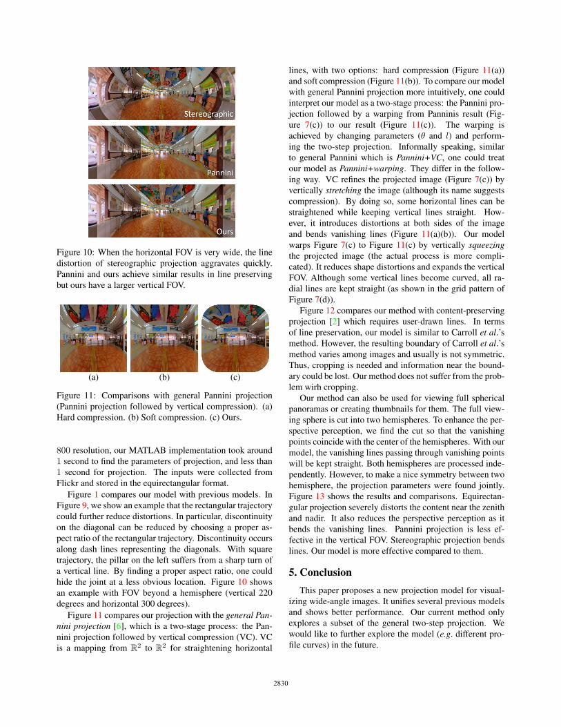
Figure 10: When the horizontal FOV is very wide, the line
distortion of stereographic projection aggravates quickly.
Pannini and ours achieve similar results in line preserving
but ours have a larger vertical FOV.
(a) (b) (c)
Figure 11: Comparisons with general Pannini projection
(Pannini projection followed by vertical compression). (a)
Hard compression. (b) Soft compression. (c) Ours.
800 resolution, our MATLAB implementation took around
1 second to find the parameters of projection, and less than
1 second for projection. The inputs were collected from
Flickr and stored in the equirectangular format.
Figure 1 compares our model with previous models. In
Figure 9, we show an example that the rectangular trajectory
could further reduce distortions. In particular, discontinuity
on the diagonal can be reduced by choosing a proper as-
pect ratio of the rectangular trajectory. Discontinuity occurs
along dash lines representing the diagonals. With square
trajectory, the pillar on the left suffers from a sharp turn of
a vertical line. By finding a proper aspect ratio, one could
hide the joint at a less obvious location. Figure 10 shows
an example with FOV beyond a hemisphere (vertical 220
degrees and horizontal 300 degrees).
Figure 11 compares our projection with the general Pan-nini projection [6], which is a two-stage process: the Pan-
nini projection followed by vertical compression (VC). VC
is a mapping from R2 to R
2 for straightening horizontal
lines, with two options: hard compression (Figure 11(a))
and soft compression (Figure 11(b)). To compare our model
with general Pannini projection more intuitively, one could
interpret our model as a two-stage process: the Pannini pro-
jection followed by a warping from Panninis result (Fig-
ure 7(c)) to our result (Figure 11(c)). The warping is
achieved by changing parameters (θ and l) and perform-
ing the two-step projection. Informally speaking, similar
to general Pannini which is Pannini+VC, one could treat
our model as Pannini+warping. They differ in the follow-
ing way. VC refines the projected image (Figure 7(c)) by
vertically stretching the image (although its name suggests
compression). By doing so, some horizontal lines can be
straightened while keeping vertical lines straight. How-
ever, it introduces distortions at both sides of the image
and bends vanishing lines (Figure 11(a)(b)). Our model
warps Figure 7(c) to Figure 11(c) by vertically squeezingthe projected image (the actual process is more compli-
cated). It reduces shape distortions and expands the vertical
FOV. Although some vertical lines become curved, all ra-
dial lines are kept straight (as shown in the grid pattern of
Figure 7(d)).
Figure 12 compares our method with content-preserving
projection [2] which requires user-drawn lines. In terms
of line preservation, our model is similar to Carroll et al.’smethod. However, the resulting boundary of Carroll et al.’smethod varies among images and usually is not symmetric.
Thus, cropping is needed and information near the bound-
ary could be lost. Our method does not suffer from the prob-
lem wirh cropping.
Our method can also be used for viewing full spherical
panoramas or creating thumbnails for them. The full view-
ing sphere is cut into two hemispheres. To enhance the per-
spective perception, we find the cut so that the vanishing
points coincide with the center of the hemispheres. With our
model, the vanishing lines passing through vanishing points
will be kept straight. Both hemispheres are processed inde-
pendently. However, to make a nice symmetry between two
hemisphere, the projection parameters were found jointly.
Figure 13 shows the results and comparisons. Equirectan-
gular projection severely distorts the content near the zenith
and nadir. It also reduces the perspective perception as it
bends the vanishing lines. Pannini projection is less ef-
fective in the vertical FOV. Stereographic projection bends
lines. Our model is more effective compared to them.
5. ConclusionThis paper proposes a new projection model for visual-
izing wide-angle images. It unifies several previous models
and shows better performance. Our current method only
explores a subset of the general two-step projection. We
would like to further explore the model (e.g. different pro-
file curves) in the future.
2830
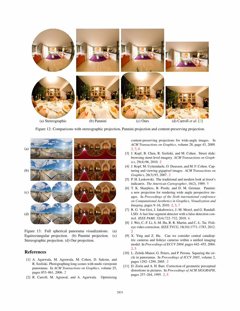
(a) Stereographic (b) Pannini (c) Ours (d) Carroll et al. [2]
Figure 12: Comparisons with stereographic projection, Pannini projection and content-preserving projection.
(a)
(b)
(c)
(d)
Figure 13: Full spherical panorama visualizations. (a)
Equirectangular projection. (b) Pannini projection. (c)
Stereographic projection. (d) Our projection.
References[1] A. Agarwala, M. Agrawala, M. Cohen, D. Salesin, and
R. Szeliski. Photographing long scenes with multi-viewpoint
panoramas. In ACM Transactions on Graphics, volume 25,
pages 853–861, 2006. 2
[2] R. Carroll, M. Agrawal, and A. Agarwala. Optimizing
content-preserving projections for wide-angle images. In
ACM Transactions on Graphics, volume 28, page 43, 2009.
2, 7, 8
[3] J. Kopf, B. Chen, R. Szeliski, and M. Cohen. Street slide:
browsing street level imagery. ACM Transactions on Graph-ics, 29(4):96, 2010. 2
[4] J. Kopf, M. Uyttendaele, O. Deussen, and M. F. Cohen. Cap-
turing and viewing gigapixel images. ACM Transactions onGraphics, 26(3):93, 2007. 2
[5] P. H. Laskowski. The traditional and modern look at tissot’s
indicatrix. The American Cartographer, 16(2), 1989. 5
[6] T. K. Sharpless, B. Postle, and D. M. German. Pannini:
a new projection for rendering wide angle perspective im-
ages. In Proceedings of the Sixth international conferenceon Computational Aesthetics in Graphics, Visualization andImaging, pages 9–16, 2010. 2, 5, 7
[7] R. G. Von Gioi, J. Jakubowicz, J.-M. Morel, and G. Randall.
LSD: A fast line segment detector with a false detection con-
trol. IEEE PAMI, 32(4):722–732, 2010. 6
[8] J. Wei, C.-F. Li, S.-M. Hu, R. R. Martin, and C.-L. Tai. Fish-
eye video correction. IEEE TVCG, 18(10):1771–1783, 2012.
2
[9] X. Ying and Z. Hu. Can we consider central catadiop-
tric cameras and fisheye cameras within a unified imaging
model. In Proceedings of ECCV 2004, pages 442–455, 2004.
2, 5
[10] L. Zelnik-Manor, G. Peters, and P. Perona. Squaring the cir-
cle in panoramas. In Proceedings of ICCV 2005, volume 2,
pages 1292–1299, 2005. 2
[11] D. Zorin and A. H. Barr. Correction of geometric perceptual
distortions in pictures. In Proceedings of ACM SIGGRAPH,
pages 257–264, 1995. 2, 5
2831
Related Documents