Record 2004-007 DRILLING MANUAL JN DUNSTER NORTHERN TERRITORY GEOLOGICAL SURVEY Northern Territory Government Department of Business, Industry & Resource Development

Welcome message from author
This document is posted to help you gain knowledge. Please leave a comment to let me know what you think about it! Share it to your friends and learn new things together.
Transcript
Record 2004-007
DRILLING MANUALJN DUNSTER
NORTHERN TERRITORY GEOLOGICAL SURVEY
Northern Territory GovernmentDepartment of Business, Industry & Resource Development
i
NORTHERN TERRITORY DEPARTMENT OF BUSINESS,INDUSTRY AND RESOURCE DEVELOPMENT
Geological Survey Record2004-007
Drilling manual
JN Dunster
Northern Territory GovernmentDepartment of Business, Industry & Resource Development
Northern Territory Geological SurveyDarwin, 2004
ii
DEPARTMENT OF BUSINESS, INDUSTRY AND RESOURCE DEVELOPMENTMINISTER: Hon Kon Vatskalis, MLACHIEF EXECUTIVE OFFICER: Mike Burgess
NORTHERN TERRITORY GEOLOGICAL SURVEYDIRECTOR: Richard Brescianini
BIBLIOGRAPHIC REFERENCE: Dunster JN, 2004. Drilling manual. Northern Territory Geological Survey, Record 2004-007.
(Record / Northern Territory Geological Survey ISSN 1443-1149)BibliographyISBN 0 7245 7085 3
Keywords: Drilling, core drilling, diamond drilling, drilling problems, RC drilling, slim hole drilling, stratigraphic drilling,wire line drilling, drilling equipment, drilling fluids
EDITORS: PD Kruse and TJ Munson
For further information contact:Geoscience InformationNorthern Territory Geological SurveyGPO Box 3000Darwin NT 0801Phone: +61 8 8999 6443Website: http://www.minerals.nt.gov.au/ntgs
© Northern Territory Government 2004
DisclaimerWhile all care has been taken to ensure that information contained in Northern Territory Geological Survey, Record 2004-007is true and correct at the time of publication, changes in circumstances after the time of publication may impact on the accuracyof its information. The Northern Territory of Australia gives no warranty or assurance, and makes no representation as to theaccuracy of any information or advice contained in Northern Territory Geological Survey, Record 2004-007, or that it issuitable for your intended use. You should not rely upon information in this publication for the purpose of making any seriousbusiness or investment decisions without obtaining independent and/or professional advice in relation to your particular situation.The Northern Territory of Australia disclaims any liability or responsibility or duty of care towards any person for loss ordamage caused by any use of, or reliance on the information contained in this publication.
kmr
http://www.minerals.nt.gov.au/ntgs
kmr
http://www.minerals.nt.gov.au/ntgs
kmr
minerals.

iii
CONTENTS
Introduction ............................................................................................................................................................................... 1Objective and content of this document .................................................................................................................................. 1History of NTGS drilling ........................................................................................................................................................1Types of drilling ...................................................................................................................................................................... 1Types of drill rigs ....................................................................................................................................................................2
Administration . .........................................................................................................................................................................4Planning and managing the program ...........................................................................................................................................4
Stage 1 Planning ...................................................................................................................................................................... 4Stage 2 Contracts management ............................................................................................................................................... 4Stage 3 Site supervision .......................................................................................................................................................... 4Stage 4 Closeout ...................................................................................................................................................................... 4
Authorisation for expenditure ..................................................................................................................................................... 4Risk analysis ................................................................................................................................................................................5
Planning and access problems .................................................................................................................................................5Technical problems while drilling ...........................................................................................................................................5Incorrect stratigraphic prognosis ............................................................................................................................................. 5
Onsite duties ................................................................................................................................................................................5Terminating the hole ................................................................................................................................................................ 6
Data handling and report writing ................................................................................................................................................6NTGS drillhole naming convention ........................................................................................................................................ 6NTGS Technical Note, Drillhole Completion Report and data management .........................................................................6
Safety and emergency procedures ............................................................................................................................................... 6Site access by trained personnel only ......................................................................................................................................6Work hours ..............................................................................................................................................................................6Site layout and housekeeping ..................................................................................................................................................6Fire safety ................................................................................................................................................................................7Fuel safety ...............................................................................................................................................................................7Hazardous substances ..............................................................................................................................................................7Safety audit and safety meetings ............................................................................................................................................. 7Personal protective equipment (PPE) .....................................................................................................................................7Personal health and hygiene .................................................................................................................................................... 7Use of radioactive sources ......................................................................................................................................................8Pressure vessels and associated equipment ............................................................................................................................. 8Guards on rig ........................................................................................................................................................................... 8Gas hazards ..............................................................................................................................................................................8
Duty of care ................................................................................................................................................................................. 9Reporting systems ...................................................................................................................................................................9Hazard Report .........................................................................................................................................................................9Incident Report ........................................................................................................................................................................9Statutory accident reporting .................................................................................................................................................... 9Vehicle accidents ...................................................................................................................................................................10Qualified first aiders ..............................................................................................................................................................10First Aid Kit - Contents List and first aid reporting ..............................................................................................................10Casualty evacuation and general rig evacuation ...................................................................................................................10Safety induction ..................................................................................................................................................................... 10Emergency communications ..................................................................................................................................................10
Core drilling .............................................................................................................................................................................10Introduction ...............................................................................................................................................................................10
Ordering core trays ................................................................................................................................................................14Drilling problems while coring .................................................................................................................................................14
Dropped core .........................................................................................................................................................................14Wedging off in the inner tube ................................................................................................................................................14Poor quality of core ............................................................................................................................................................... 14
Core handling procedures ......................................................................................................................................................... 14Preparing core trays ............................................................................................................................................................... 14Lining core trays ....................................................................................................................................................................14Core catching .........................................................................................................................................................................16Edge matching, washing and core orientation lines ..............................................................................................................16Labelling driller’s blocks ......................................................................................................................................................16

iv
Dealing with lost core ............................................................................................................................................................17Measuring and depth labelling ..............................................................................................................................................17Core sample depths ...............................................................................................................................................................17Arrow up ................................................................................................................................................................................17Labelling core trays ...............................................................................................................................................................17Determining absolute core orientation and measuring true dip and strike ...........................................................................17Recording maximum dip in core ...........................................................................................................................................20Calculating true stratigraphic thickness and Stratigraphic Efficiency ..................................................................................20
Example 1 ..........................................................................................................................................................................20Example 2 ..........................................................................................................................................................................20
Photographing core ...............................................................................................................................................................20Describing core .....................................................................................................................................................................21Packing and palletising core trays and their weight ..............................................................................................................21Slabbing core and composite core sampling .........................................................................................................................21
Hydrocarbon description ...........................................................................................................................................................21Signs of gas in core ...............................................................................................................................................................22Oil shows in core ...................................................................................................................................................................22
Oil bleeds ...........................................................................................................................................................................23Sealing oil-soaked core .....................................................................................................................................................23Fluorescence ......................................................................................................................................................................23Cut and solvent tests ..........................................................................................................................................................23Acid bounce test ................................................................................................................................................................25Hot water extraction ..........................................................................................................................................................25Standardised oil show description .....................................................................................................................................25Spurious hydrocarbon indications .....................................................................................................................................27
Collection and assay of non-core samples .............................................................................................................................28Rotary open hole samples .....................................................................................................................................................28
Sample collection and labelling ........................................................................................................................................28Sample contamination .......................................................................................................................................................29
Water samples ........................................................................................................................................................................29Oil samples ............................................................................................................................................................................29
Engineering ..............................................................................................................................................................................29Engineering information in daily drilling reports .................................................................................................................29Casing ....................................................................................................................................................................................29Drilling fluids ........................................................................................................................................................................31Drilling fluid parameters .......................................................................................................................................................31Drilling fluid additives ..........................................................................................................................................................32Engineering design of typical cored stratigraphic drillholes ................................................................................................32Hole orientation and deviation ..............................................................................................................................................32
Electronic memory tools ...................................................................................................................................................35Eastman camera .................................................................................................................................................................35Mechanical controlled vertical drift indicators .................................................................................................................37Electric wireline surveys ...................................................................................................................................................37
Plotting azimuth and declination / drift and deviation ..........................................................................................................37Calculating true vertical depth and horizontal displacement ................................................................................................37
Example 3 ..........................................................................................................................................................................37Survey data presentation in NTGS reports ...........................................................................................................................39
Drilling Problems ....................................................................................................................................................................39Drilling problems associated with the formation ......................................................................................................................39
Taking a kick and a blowout ..................................................................................................................................................39Abnormal formation pressure ................................................................................................................................................39
Detecting overpressure ......................................................................................................................................................39Artesian water ........................................................................................................................................................................40Lost circulation ......................................................................................................................................................................40Differential sticking ...............................................................................................................................................................40Spin out ..................................................................................................................................................................................41Solids in the annulus ..............................................................................................................................................................41Salt .........................................................................................................................................................................................41
Drilling problems associated with downhole equipment ..........................................................................................................41Key seating ............................................................................................................................................................................41Drillstring washout ................................................................................................................................................................41

v
Rusty drillstring ..................................................................................................................................................................... 42Bent rods or drillpipe ............................................................................................................................................................42Parted drillstring ....................................................................................................................................................................42Undergauge hole ....................................................................................................................................................................43Bit failure ...............................................................................................................................................................................43Wireline breakage ..................................................................................................................................................................43Fishing ...................................................................................................................................................................................43
Surface equipment failure ......................................................................................................................................................... 43Wireline logging and vertical seismic profiling ....................................................................................................................43Wireline logging ........................................................................................................................................................................ 43
Preparations ........................................................................................................................................................................... 44Wiper trip ........................................................................................................................................................................... 44Conditioning and sampling the drilling fluid prior to wireline logging ............................................................................45Recording datum and depth ...............................................................................................................................................45
Safety .........................................................................................................................................................................................45Logging suite .........................................................................................................................................................................45
Mechanical caliper ............................................................................................................................................................45Natural gamma ray ............................................................................................................................................................46Spontaneous potential (SP) ..............................................................................................................................................46Resistivity and conductivity ..............................................................................................................................................47Induced polarisation (IP) ................................................................................................................................................... 47Magnetic susceptibility ......................................................................................................................................................47Sonic ..................................................................................................................................................................................48Density ...............................................................................................................................................................................48Neutron ..............................................................................................................................................................................49Dipmeter ............................................................................................................................................................................49Downhole temperature ......................................................................................................................................................49
Velocity survey and vertical seismic profiling ......................................................................................................................50Downhole loss of wireline equipment ....................................................................................................................................... 50Completion and abandonment ................................................................................................................................................... 50
Subsurface plugs ....................................................................................................................................................................50Surface plugs for open holes .................................................................................................................................................50
Surface plugs for collared drillholes including NTGS stratigraphic holes .......................................................................50Plugs for uncollared RAB holes ........................................................................................................................................51
Waterbore completion ............................................................................................................................................................51Site restoration........................................................................................................................................................................... 51Acknowledgements and disclaimers ...................................................................................................................................... 51Bibliography ............................................................................................................................................................................52Appendix 1 – Online resources ..............................................................................................................................................54Appendix 2 – Glossary of commonly used abbreviations ....................................................................................................55Appendix 3 – Daily Operations Report ................................................................................................................................. 56Appendix 4 – NTGS Drilling Log .......................................................................................................................................... 58Appendix 5 – Hydrocarbon Show Log .................................................................................................................................. 60Index ......................................................................................................................................................................................... 62
1
INTRODUCTION
NTGS has an obligation to provide geological information in areas of poor outcrop and inadequate drillhole coverage. Despitethe best geophysical data, this can only be reliably addressed by stratigraphic drilling, where such drillholes provide lithologicaland stratigraphic information and allow collection of pristine samples for biostratigraphic, geochemical, geochronological andmineralisation studies. These data can then be used to build regional geological models and encourage exploration companiesinto new areas. Considering the paucity of outcrop and the limited coverage of existing drillholes over much of the NorthernTerritory, there is an ongoing need for the NTGS to undertake drilling programs. In addition, drilling undertaken by NTGSshould be documented in a way that allows explorers to optimise their own drilling programs.
Objective and content of this document
This in-house manual is designed to assist NTGS staff in organising stratigraphic drilling programs and supervising on site. Itis directed to those with little or no previous experience of drilling. It gives in-house guidelines and does not purport toreiterate government policy concerning drilling, unless this is explicitly acknowledged. It is not a textbook on drilling nor is itintended to be as comprehensive as company manuals. For comparison, the 1996 Santos onshore drilling operations manual isover 400 pages in length, including 58 pages of forms. In the present manual, much of the drillers’ jargon is explained inreferences listed in Appendix 1, and a glossary of common abbreviations provided in Appendix 2. Australian Standards referredto throughout the document are shown in the format AS1234. The symbol % is used to indicate guidelines, procedures andchecks for the NTGS site Representative. The symbol � is used to distinguish worked examples of calculations. An indexprovides quick reference to specific topics.
It is anticipated that this document will be revised regularly, and any corrections or comments should be directed to theauthor or the Editorial Geologist.
History of NTGS drilling
The various governments responsible for what is now the Northern Territory have been involved in drilling for almost acentury. No specific drilling reports were published prior to 1908 when the Territory was administered from South Australia,but summaries were included in earlier annual reports at least as far back as 1905. The first internal review of drilling activitiesby the NT government was undertaken in 1912 by HI Jensen, the then Director of Mines. He rationalised the 250 rapidlydecaying boxes of core stored in the Government Stables, ‘put an end to the old system of boring at random’ and ‘introducedbusiness methods into the work of the drills’ (Jensen 1915). He reported that during 1912-1913 eight holes totalling 3626’(1105 m) were drilled using steam-powered diamond rigs at known prospects. The average cost was £1 15s 2½d per foot.
The Mines Branch, as it was called, continued to drill prospects at the behest of leaseholders until its demise in the late1970s. From NT self-government and the birth of NTGS in 1978, the emphasis shifted to stratigraphic drilling as a complementto geological mapping. Another government division is responsible for waterbore drilling but their samples are stored in NTGScore libraries. As of July 2003, 644 NT government water and stratigraphic drillholes totalling over 57 000 m had been registeredin our COREDAT database. The average depth is 88.8 m; 155 holes are ≥100 m and 19 of the holes exceed 500 m, the deepestto date being 845.9 m.
Types of drilling
The various types of drilling may be classified according to the hole-making action and the hole cleaning method. Those ofrelevance to NTGS are described below.
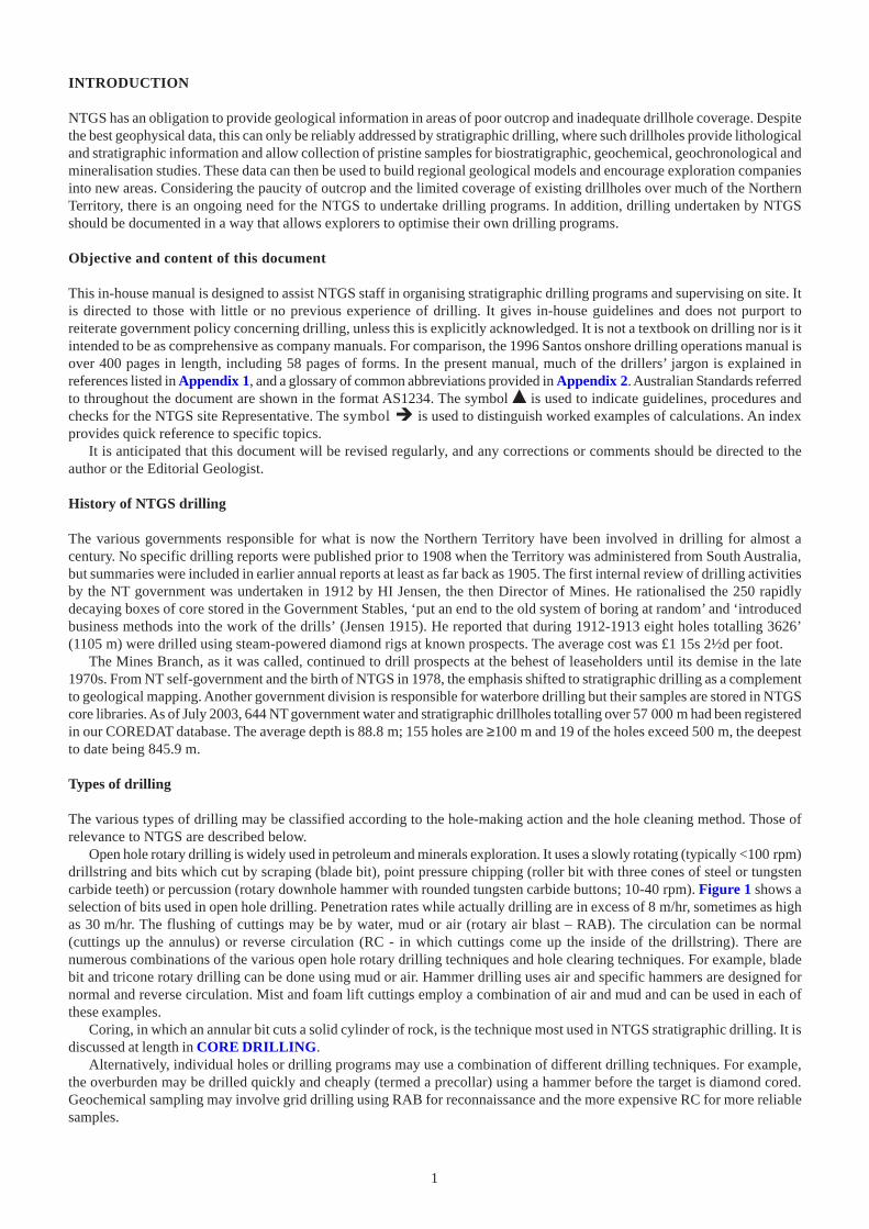
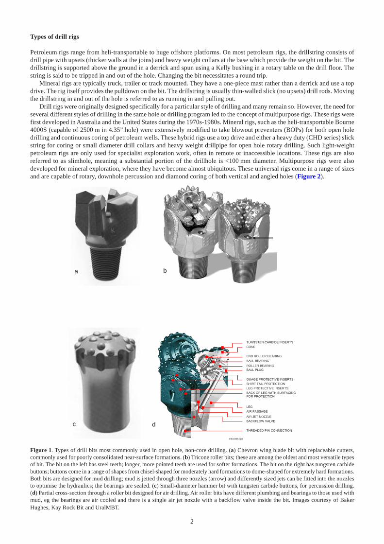
Open hole rotary drilling is widely used in petroleum and minerals exploration. It uses a slowly rotating (typically <100 rpm)drillstring and bits which cut by scraping (blade bit), point pressure chipping (roller bit with three cones of steel or tungstencarbide teeth) or percussion (rotary downhole hammer with rounded tungsten carbide buttons; 10-40 rpm). Figure 1 shows aselection of bits used in open hole drilling. Penetration rates while actually drilling are in excess of 8 m/hr, sometimes as highas 30 m/hr. The flushing of cuttings may be by water, mud or air (rotary air blast – RAB). The circulation can be normal(cuttings up the annulus) or reverse circulation (RC - in which cuttings come up the inside of the drillstring). There arenumerous combinations of the various open hole rotary drilling techniques and hole clearing techniques. For example, bladebit and tricone rotary drilling can be done using mud or air. Hammer drilling uses air and specific hammers are designed fornormal and reverse circulation. Mist and foam lift cuttings employ a combination of air and mud and can be used in each ofthese examples.
Coring, in which an annular bit cuts a solid cylinder of rock, is the technique most used in NTGS stratigraphic drilling. It isdiscussed at length in CORE DRILLING.
Alternatively, individual holes or drilling programs may use a combination of different drilling techniques. For example,the overburden may be drilled quickly and cheaply (termed a precollar) using a hammer before the target is diamond cored.Geochemical sampling may involve grid drilling using RAB for reconnaissance and the more expensive RC for more reliablesamples.
2
Types of drill rigs
Petroleum rigs range from heli-transportable to huge offshore platforms. On most petroleum rigs, the drillstring consists ofdrill pipe with upsets (thicker walls at the joins) and heavy weight collars at the base which provide the weight on the bit. Thedrillstring is supported above the ground in a derrick and spun using a Kelly bushing in a rotary table on the drill floor. Thestring is said to be tripped in and out of the hole. Changing the bit necessitates a round trip.
Mineral rigs are typically truck, trailer or track mounted. They have a one-piece mast rather than a derrick and use a topdrive. The rig itself provides the pulldown on the bit. The drillstring is usually thin-walled slick (no upsets) drill rods. Movingthe drillstring in and out of the hole is referred to as running in and pulling out.
Drill rigs were originally designed specifically for a particular style of drilling and many remain so. However, the need forseveral different styles of drilling in the same hole or drilling program led to the concept of multipurpose rigs. These rigs werefirst developed in Australia and the United States during the 1970s-1980s. Mineral rigs, such as the heli-transportable Bourne4000S (capable of 2500 m in 4.35” hole) were extensively modified to take blowout preventers (BOPs) for both open holedrilling and continuous coring of petroleum wells. These hybrid rigs use a top drive and either a heavy duty (CHD series) slickstring for coring or small diameter drill collars and heavy weight drillpipe for open hole rotary drilling. Such light-weightpetroleum rigs are only used for specialist exploration work, often in remote or inaccessible locations. These rigs are alsoreferred to as slimhole, meaning a substantial portion of the drillhole is <100 mm diameter. Multipurpose rigs were alsodeveloped for mineral exploration, where they have become almost ubiquitous. These universal rigs come in a range of sizesand are capable of rotary, downhole percussion and diamond coring of both vertical and angled holes (Figure 2).
m04-068.dgn
a b
c d
CONE
TUNGSTEN CARBIDE INSERTS
END ROLLER BEARING
BALL BEARING
ROLLER BEARINGBALL PLUG
GUAGE PROTECTIVE INSERTSSHIRT TAIL PROTECTIONLEG PROTECTIVE INSERTS
LEG
AIR PASSAGE
AIR JET NOZZLEBACKFLOW VALVE
THREADED PIN CONNECTION
BACK OF LEG WITH SURFACINGFOR PROTECTION
Figure 1. Types of drill bits most commonly used in open hole, non-core drilling. (a) Chevron wing blade bit with replaceable cutters,commonly used for poorly consolidated near-surface formations. (b) Tricone roller bits; these are among the oldest and most versatile typesof bit. The bit on the left has steel teeth; longer, more pointed teeth are used for softer formations. The bit on the right has tungsten carbidebuttons; buttons come in a range of shapes from chisel-shaped for moderately hard formations to dome-shaped for extremely hard formations.Both bits are designed for mud drilling; mud is jetted through three nozzles (arrow) and differently sized jets can be fitted into the nozzlesto optimise the hydraulics; the bearings are sealed. (c) Small-diameter hammer bit with tungsten carbide buttons, for percussion drilling.(d) Partial cross-section through a roller bit designed for air drilling. Air roller bits have different plumbing and bearings to those used withmud, eg the bearings are air cooled and there is a single air jet nozzle with a backflow valve inside the bit. Images courtesy of BakerHughes, Kay Rock Bit and UralMBT.

3
a b
c
d e
f g
h
i
j
m04-069.dgn
Figure 2. Multipurpose rigs. (a) UDR 650 MKII, a medium-sized multipurpose rig, reverse circulation (RC) drilling an angled hole; notethe flowline connection that enables the drilling fluid to be circulated down the annulus, bringing the cuttings up the inside of the drillstring.This rig is capable of RC hammer to 280 m with 3.5" rods. (b) The same rig as in (a), diamond coring in NQ diameter. It is capable of coringHQ to 575 m and NQ to 875 m. (c) Carrier-mounted UDR 5000 jacked up as a platform. This is one of the largest UDR multipurpose rigs,rivalling some conventional petroleum rigs in depth capacity, capable of downhole hammering to 1830 m with 3.5" rods and of coringCHD101 to 2960 m. (d) Bourne THD25, a medium-sized rig designed and built in Queensland, used for waterbore drilling and shallowmineral exploration. It would normally be truck mounted; the hydraulic top head drive is visible at the bottom of its travel and the driller’splatform and controls are to the left. (e) UDR 1000 on a platform in Papua-New Guinea. A standard UDR 1000 is capable of RC hammeringto 415 m with 3.5" rods and of coring HQ to 1000 m and NQ to 1500 m. (f) Drillcorp rig 53, a UDR 1000 mounted on an 8x8 Man truck,showing the rod rack on the right side of the rig. (g) Boart Longyear UDR 1000, similar to the previous, showing the left side of the rig withpumps, compressor and driller’s platform. (h) Truck-mounted UDR 1000 drilling an angled hole. (i) Truck-mounted UDR 1200, capable ofRC hammering to 550 m with 4.5" rods and of coring PQ to 820 m, HQ to 1100 m and NQ to 1650 m. (j) UDR 1500 shown jacked onto itsplatform with the mast set to drill an angled hole; the caterpillar tracks used to transport it are visible to the left. A UDR 1500 MKIII canhammer to almost 1000 m and core CHD101 to 1680 m and NQ to 2780 m. Images courtesy of Bournedrill, Drillcorp and UDR.
4
ADMINISTRATION
This section presents checklists and brief summaries to assist in the planning, execution and supervision of a drilling program.Safety and duty of care are discussed.
PLANNING AND MANAGING THE PROGRAM
% Stage 1 Planning
• Define drillhole(s) objectives• Organise access with Traditional Owners and other stakeholders• Prioritise order of drilling• Prepare Drillhole Proposal(s)• Prepare Authorisation for Expenditure (AFE –see AUTHORISATION FOR EXPENDITURE)• Purchase long lead time consumables• Finalise Invitations to Tender• Organise earthworks (build roads, dams, dig pits etc)• Assure secondary water supply• Prepare draft work flowchart• Evaluate tenders• Collect intelligence• Model costs• Inspect equipment• Interview key contractor personnel
% Stage 2 Contracts management
• Award contracts• Organise site inspection by representative of drilling company• Refine work flowchart• Obtain any necessary insurance
% Stage 3 Site supervision
• Coordinate mobilisation and inter-drillhole moves• Undertake site duties (see ONSITE DUTIES)
% Stage 4 Closeout
• Site restoration• Depermit all stakeholders• Appraise contractors and NTGS performance• Audit project• Prepare Technical Note and Drillhole Completion Report
AUTHORISATION FOR EXPENDITURE
A drilling budget should include:
• Permitting and depermitting• Water supply (waterbore drilling and/or haulage)• Roadworks• Roadworks supervision• Site preparation• Site preparation supervision• Rig mobilisation/moves/demobilisation• Rig day rates• Camp• Fuel/lubricants and delivery• Casing• Bits and drilling consumables

5
• Mud supply and engineering• Wireline logging and vertical seismic profiling• Travel and accommodation• Freight• Field supplies and equipment• Analyses• Drilling Proposal/Technical Note/Drilling Completion Report• Insurance• Communications• Site restoration• Road repairs• Contingency
RISK ANALYSIS
Anticipating and assessing the risks or potential problems is part of any project plan. In drilling, the emphasis in risk analysiswill vary from one proposal to another. The checklist below gives examples of common risks. Quantitative comparisons arepossible if the seriousness of the various facets of the program and their likelihood are each given a rating from one to ten withone being the least serious and least likely. The weighted average then ranks the relative risk of this particular proposal.
Once identified and prioritised, potential problems need to be matched with preventative actions, contingent plans oradequate solutions.
Planning and access problems
• Delays in Aboriginal clearance• Problems with access logistics for mobilisation/demobilisation/interhole moves• Difficulties with crew change• Unable to get fuel to site
Technical problems while drilling
• Insufficient/unreliable water supply• Bad weather delaying operations• Lost circulation• Fractured formation• Overpressured formation• Unsafe hydrocarbon intersection• Intersecting faults or inclined bedding• Intersecting evaporites• No backup and replacement equipment has to be mobilised
Incorrect stratigraphic prognosis
• Stratigraphic prognosis too shallow, hole deeper than anticipated• Original target beyond rig capacity
ONSITE DUTIES
% NTGS must maintain a technical presence on site from the arrival of the rig to mast down. The NTGS Geologist andTechnical Assistants are responsible for the following duties:
• Survey the drillhole location with GPS and ensure that the rig is set up appropriately (especially for an angled hole)• Ensure that all work is carried out in accordance with relevant legislation and under the terms of contracts• Check and sign contractors’ daily operations reports (sometimes called DORs, DDRs, plods or tour sheets). They must be
completed and signed daily and not allowed to accumulate. The driller will probably also have separate time sheets andsafety checks to sign
• Brief all site personnel on NTGS guidelines concerning safety and confidentiality• Organise and chair weekly safety meetings• Recommend the sample interval during rotary drilling• Supervise collection of all samples• Ensure core and other samples are handled, marked and labelled according to best practice
6
• Provide a detailed geological description• Detect and describe all potentially economically important aspects (eg oil shows, ore minerals)• Provide an NTGS Daily Operations Report in a standard format (Appendix 3)• Monitor costs relative to budget• Photograph core• Arrange transport of core and other materials• Advise of termination depth (see Terminating the hole)• Witness and QC wireline logging operations• Supervise completion or abandonment of the hole in accordance with relevant legislation• Provide photographic evidence and sign-off on environmental impact closeout
Terminating the hole
% Under normal circumstances, the NTGS Geologist on site will recommend when to terminate the hole. On a deep stratigraphichole, a cutoff will have been clearly defined as part of the proposal (eg into top of igneous basement). If the hole is to begeophysically logged, remember to allow sufficient sump to enable meaningful readings of the lowermost geological unit (inthis example, basement). Some of the large combo suites used in petroleum exploration need a 30 m sump; whereas 3 m mightbe adequate with other tools.
DATA HANDLING AND REPORT WRITING
NTGS drillhole naming convention
The NTGS drillhole naming convention is:MapSheet code (two letters)_Year (last two digits)_Hole type (DD, RC, AC, RB) _Hole number (two digits)eg VR03DD01 is the first diamond hole drilled in VICTORIA RIVER DOWNS in 2003. Drillhole names are best determinedearly, during preparation of the Drillhole Proposal(s) or Invitations to Tender. The list of MapSheet codes to be used with theconvention is to be found at:G:\Geological Survey\Administration\Standards & Procedures\GIS\File naming\NTGS_File_Names.xls
NTGS Technical Note, Drillhole Completion Report and data management
% All relevant background data from the drilling will be compiled into an NTGS Technical Note in a standard format (specifiedin separate guidelines). These data will be simplified and accompanied by a comprehensive interpretative report in the finalDrillhole Completion Report. The geologist responsible for the project is also to provide all necessary metadata in standardNTGS format.
SAFETY AND EMERGENCY PROCEDURES
The following are basic checklists relating to safety and emergency procedures for drilling operations.
Site access by trained personnel only
• Only trained personnel on site• Barriers to prevent access by unauthorised personnel• Contractors are not to grant ingress to any third party without the consent of the NTGS Representative
Work hours
• Shift duration• Tour of duty (duration of field period)• Adequate light• Working in extreme conditions (avoiding heat stroke)
Site layout and housekeeping
• Good site layout, ground stability, drainage, flood and fire risk, wind direction to camp• Access and turning circles for support trucks and service vehicles• Remove any obstructions (loose rocks, tree stumps) from site• All rigs should ideally be fitted with elevated walkways (AS1657 compliant) to create a uniform work platform, irrespective
of local site conditions
7
• No slippery walkways• Check for underground cables and pipes• Good housekeeping; site clean and tidy and free of tripping hazards• Tubular items stacked in safe manner• Safety signs must be displayed (AS1319)• Any requirement for quarantine and disease control, for example steps to avoid spreading noxious weeds
Fire safety
• Fire breaks and fire fighting equipment; fire bans include campfires• Fire extinguishers (AS1841, AS1845-48, AS1851 Part 1, AS2444)• If rig is fitted with an automatic fire suppression system, include familiarisation in safety induction• Fire prevention during welding (AS1674)• Oxygen (from oxyacetylene) is not to contact hydrocarbons (eg grease or petrol) as this is potentially explosive
Fuel safety
• Trayback NTGS vehicles are limited in the number of 200 L fuel drums they may carry on a gazetted road without a permit (referto NTGS Field Manual)
• Fuel stored away from rig and camp in accordance with regulations (eg tanks may require a bund wall)• Spills or leakage of fuel for the use of Contractor are their responsibility but NTGS will monitor clean-up
Hazardous substances
• Appropriate signage in place• Materials Safety Data Sheets for all potentially toxic or hazardous drilling additives• Safe disposal of all potentially toxic wastes• Spills or leakage of hazardous substances for the use of Contractor are their responsibility, clean-up is under NTGS supervision
Safety audit and safety meetings
• Site safety audit before spud• % NTGS should organise weekly safety meetings of each shift, to include both NTGS and all contract personnel. Such meetings
must be recorded in the Daily Operations Report
Personal protective equipment (PPE)
• Head: hard hats (AS1800, 1801, 2210) must be worn within 30 m of the rig. Note that metal hard hats are not permitted;allowable accessories include sun brim, visor-type face shield, earmuff attachments, lampholder. Long hair must be restrained,even when a hard hat is worn
• Eye: safety glasses (AS1336:1982, AS1337), tinted or otherwise, must have the appropriate Australian Standard logo; weldingshields (AS1338): a full-face shield is to be worn when cutting core. Filters in fluoroscopes and UV boxes (AS1338 Part 2)
• Hearing: hearing protection device shall provide protection to a level not exceeding 85 dB (AS1270). This can be earmuffs,disposable ear plugs or both, such that they do not compromise other safety equipment
• Respiratory: respiratory protection against dust (AS1715, AS1716). Breathing apparatus may be carried on some rigs and its userequires formal training
• Skin: sunscreen and insect repellent will be supplied by the employer• Hand: general work gloves (AS2161), welding gloves (AS1558)• Foot: safety boots (AS2210) with a steel toe cap must be worn by all personnel within 30 m of an operating drill rig; boots must
have the Australian Standard logo• Clothing: safe and adequate clothing, no loose clothing, a UPF (UV) rating of 50+. Some companies stipulate that long-sleeved
shirts and long trousers be worn on drill rigs; welding apron, raincoats• Harness: all personnel aloft must have a safety belt or safety harness (AS1891, AS2626). Note that these standards forbid the use
of harnesses made from leather or natural fibre webbing. No tools to be hand carried into the mast
Personal health and hygiene
• Any medical condition that may affect Contractor performance must be reported to the NTGS Representative• Be aware of high-risk individuals (eg asthmatics, diabetics, epileptics, angina sufferers)• Prohibition of drugs; control of alcohol• Camp conditions, especially food preparation areas and ablutions are to be clean and hygienic
8
• Adequate rubbish and sanitary disposal facilities• Firearms, bows or similar weapons are prohibited• Domestic animals are prohibited• Occupational driving (AS2299)
Use of radioactive sources
Use of a radioactive source in downhole logging requires a licence under the Radiation Health Act. Any radioactive sources for usein downhole logging must be transported, stored and handled in accordance with the Commonwealth NHMR Code of practice for thesafe transport of radioactive substances and Code of practice for the safe use of sealed radioactive sources in borehole logging.Requirements for signage on vehicles carrying sources must be enforced.
Pressure vessels and associated equipment
• Must comply with AS3788, AS3873• All high-pressure hoses must be restrained to prevent whipping in the event of breakage or connection failure. Particular attention
should be paid to the adequacy and placement of the restraining line between the sample hose and the cyclone on an air rig(failure has caused fatalities and serious injuries in Australia)
• Pressure relief valves (mandatory on air compressors, triplex and water injection pumps) should be function tested wherepossible. No shutoff valve is permitted between the pressure relief valve and the pressure chamber
• Compressed air handtools such as button bit grinders must only be operated through a pressure regulator• Take care when pumping out inner tubes with drilling fluid or water. Use of compressed air is forbidden; a bumper must be in
place and noone within 5 m
Guards on rig
• Hydraulic rod spinners should be fitted to minimise rod handling and ideally, safety cages installed to protect rig personnel whiledrilling is in progress. These cages should be fitted with a hydraulic interlock which immediately stops rod rotation when thecage is opened
• Check guards on belts, chains and gears
Gas hazards
Petroleum gas is the most common hazardous gas encountered while drilling. CO2 and H2S are also potential problems and canbe associated with petroleum gas (up to 28% of natural gas could be H2S) or gas-charged groundwater. Both petroleum gas andH2S are explosive. These and CO2 can all be fatal if breathed in sufficient concentrations. Ensure that all personnel are informedif gas is encountered. The driller will decide how to treat the problem, what fire prevention strategy to adopt, and if rig and/orcamp evacuation needs to be considered.
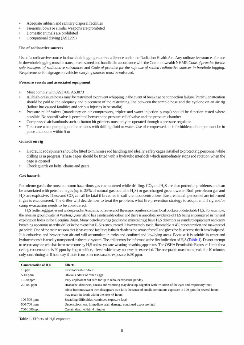
H2S (rotten egg gas) is not widespread in Australia, but several of the major aquifers contain local pockets of detectable H2S. For example,the artesian groundwater at Winton, Queensland has a noticeable odour and there is anecdotal evidence of H2S being encountered in mineralexploration holes in the Georgina Basin. Many petroleum rigs (and some mineral rigs) have H2S detectors as standard equipment and carrybreathing apparatus near the driller in the event that H2S is encountered. It is extremely toxic, flammable at 4% concentration and makes steelgo brittle. One of the main reasons that it has caused fatalities is that it deadens the sense of smell and gives the false sense that it has dissipated.It is colourless and heavier than air and will accumulate in tanks and confined and low-lying areas. Because it is soluble in water andhydrocarbons it is readily transported in the mud system. The driller must be informed at the first indication of H2S (Table 1). Do not attemptto rescue anyone who has been overcome by H2S unless you are wearing breathing apparatus. The OSHA Permissible Exposure Limit for aceiling concentration is 20 ppm hydrogen sulfide, a level which may not ever be exceeded. The acceptable maximum peak, for 10 minutesonly, once during an 8 hour day if there is no other measurable exposure, is 50 ppm.
Table 1. Effects of H2S exposure.
Concentration of H2S Effects
10 ppb First noticeable odour
5-10 ppm Obvious odour of rotten eggs
10-20 ppm Very unpleasant but safe for up to 8 hours exposure per day
20-100 ppm Headache, dizziness, nausea and vomiting may develop, together with irritation of the eyes and respiratory tract;
odour becomes sweet then disappears as it kills the sense of smell; continuous exposure to 100 ppm for several hours
may result in death within the next 48 hours
100-500 ppm Breathing difficulties; continued exposure fatal
500-700 ppm Unconsciousness, immediate brain damage; continued exposure fatal
700-1000 ppm Certain death within 4 minutes
9
DUTY OF CARE
Reporting systems
All contractors must have their own internal accident reporting system. The current reporting systems used to record OHS data withinNT Government are:
• Hazard Report• Incident Report: to record all incidents including near misses• Incident Investigation: to record investigation details and outcomes
% Managers/Supervisors must ensure that all relevant forms are easily accessible and that they are completed and processed inaccordance with the requirements of the OHS management system. They must also ensure that all employees are familiar with theforms and their responsibilities to use them. First Aid Kit - Contents List form ensures that kits have adequate materials and recordsuse of first aid materials. Forms are available at:http://uluru.nt.gov.au/dbird/ohs/pages/management_system.htm#ohsmgtsystemAll completed forms are to be returned to the supervisor.
An external NT Fleet Motor Vehicle Accident form is raised when any NT Fleet vehicle has been damaged. As well, an externalDCIS Accident Report is raised when there is an injury to an employee and any of the following conditions apply:
• Employee(s) involved will be absent from work for one full day/shift or more (lost time)• Hospitalisation is required• The attention of a medical practitioner (this includes community nurses) is required• Workers Compensation will be, or has the potential to be claimed (medical, pharmacy, physiotherapy, rehabilitation, etc)
Hazard Report
Any hazard that has the potential to cause injury or illness to an employee, visitor, contractor or member of the publicmust be reported and assessed using the prescribed Hazard Report form.
Incident Report
All incidents and any workplace-related illness must be reported on the Incident Report form. If the person involved isunable to do so, the supervisor or witness will complete the form as soon as possible. Any other witnesses shouldindependently complete forms.
Statutory accident reporting
The HR Manager is required to report all prescribed accidents to the Work Health Authority within 24 hours, followed bya written report within 7 days. An external two-page DCIS Accident Report Form is used for this.
The standard NT Government definition of a prescribed accident is when:
• A death occurs• The accident is likely to result in more than 5 days lost time• A worker suffers an electrical shock• Exposure to a hazardous substance results in admission to hospital• The accident results in injury to a person other than a worker• Overturning, collapse or failure of a lift, crane, hoist, lifting gear or scaffolding occurs (this would include the rig
mast)• Failure of pressure equipment is involved• A height of more than 1.5 m of an excavation or shoring collapses• Part of a building or structure collapses• Fire or explosion results in normal work being stopped for more than 24 hours (see added comment below)• An accident involves plant coming into contact with live electrical conductors, or• Personal protective equipment fails affecting the health and safety of a person.
In the case of drilling we need to add:
• Any drillhole flows uncontrolled• Any combustion of material in or flowing from a drillhole occurs
10
The scene of any such accident must be rendered safe, but otherwise disturbed as little as possible. Photographs maybe advantageous. A safety inspector will probably need to visit the site.
Vehicle accidents
It is a legal requirement that all motor vehicle accidents resulting in bodily injury or damage are reported to the police as soonas possible. If an NT Fleet vehicle is damaged, an external NT Fleet Motor Vehicle Accident form must be completed andforwarded to the Office Services Manager. This form is in addition to the internal DBIRD Incident Report and IncidentInvestigation forms, which still have to be completed.
Qualified first aiders
The drilling Contractor’s crew should include a designated first aid officer who has a minimum Senior First Aid qualification.This should be documented in the contract and records kept on site. All NTGS personnel on the rig site should have currentsimilar qualifications.
First Aid Kit - Contents List and first aid reporting
The First Aid Kit - Contents List ensures that kits have adequate materials and records use of first aid materials. Managers andsupervisors are to inform all employees of the location of the nearest first aid kit and the nominated First Aider. Whereapplicable, they are also to include a copy of the procedures to be followed with all first aid equipment. The Manager of thework area will ensure that a procedure is implemented to restock the First Aid kits on a regular basis. If a situation ariseswhereby an employee requires first aid treatment, the Manager should record the materials used from the first aid kit on theform provided inside the kit. The nominated First Aider will collect and forward these forms to the HR Manager for collationand review of first aid usage. This procedure does not replace the requirement to notify all incidents to your Supervisor as soonas possible.
Casualty evacuation and general rig evacuation
% As part of the NTGS Field Plan, casualty evacuation and general rig evacuation procedures must be formulated in consultationwith the drilling Contractor and submitted to the NTGS Field Supervisor before drilling commences. A Royal Flying DoctorService-approved airstrip has to be nominated for evacuation. Ideally, there should be all-weather access to and from theairstrip. If not, contingencies for helicopter evacuation should be put in place. Remember that not all helicopters can carry astretcher.
Safety induction
% All rig-site personnel should receive a safety induction specific to the rig and location before their first shift. This includesall NTGS, contract and subcontract personnel. This should be documented in writing.
Emergency communications
% In addition to the satellite phone/fax on site, the NTGS Field Plan should include at least one form of standby communicationsthat can be relied upon in an emergency. This may be VHF/UHF radio or the drillers’ satellite phone. Note that if vehicle-mounted satellite phones are used there must be at least one such NTGS vehicle on site at all times.
CORE DRILLING
INTRODUCTION
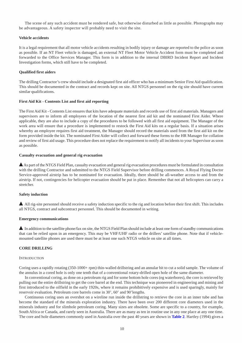
Coring uses a rapidly rotating (350-1000+ rpm) thin-walled drillstring and an annular bit to cut a solid sample. The volume ofthe annulus in a cored hole is only one tenth that of a conventional rotary-drilled open hole of the same diameter.
In conventional coring, as done on a petroleum rig and for some bottom hole cores (eg waterbores), the core is retrieved bypulling out the entire drillstring to get the core barrel at the end. This technique was pioneered in engineering and mining andfirst introduced to the oilfield in the early 1920s, where it remains prohibitively expensive and is used sparingly, mainly forreservoir evaluation. Petroleum core barrels come in 30’, 60’ and 90’lengths.
Continuous coring uses an overshot on a wireline run inside the drillstring to retrieve the core in an inner tube and hasbecome the standard of the minerals exploration industry. There have been over 200 different core diameters used in theminerals industry and for slimhole petroleum coring. Many sizes are obsolete. Some are specific to a country, for example,South Africa or Canada, and rarely seen in Australia. There are as many as ten in routine use in any one place at any one time.The core and hole diameters commonly used in Australia over the past 40 years are shown in Table 2. Hartley (1994) gives a
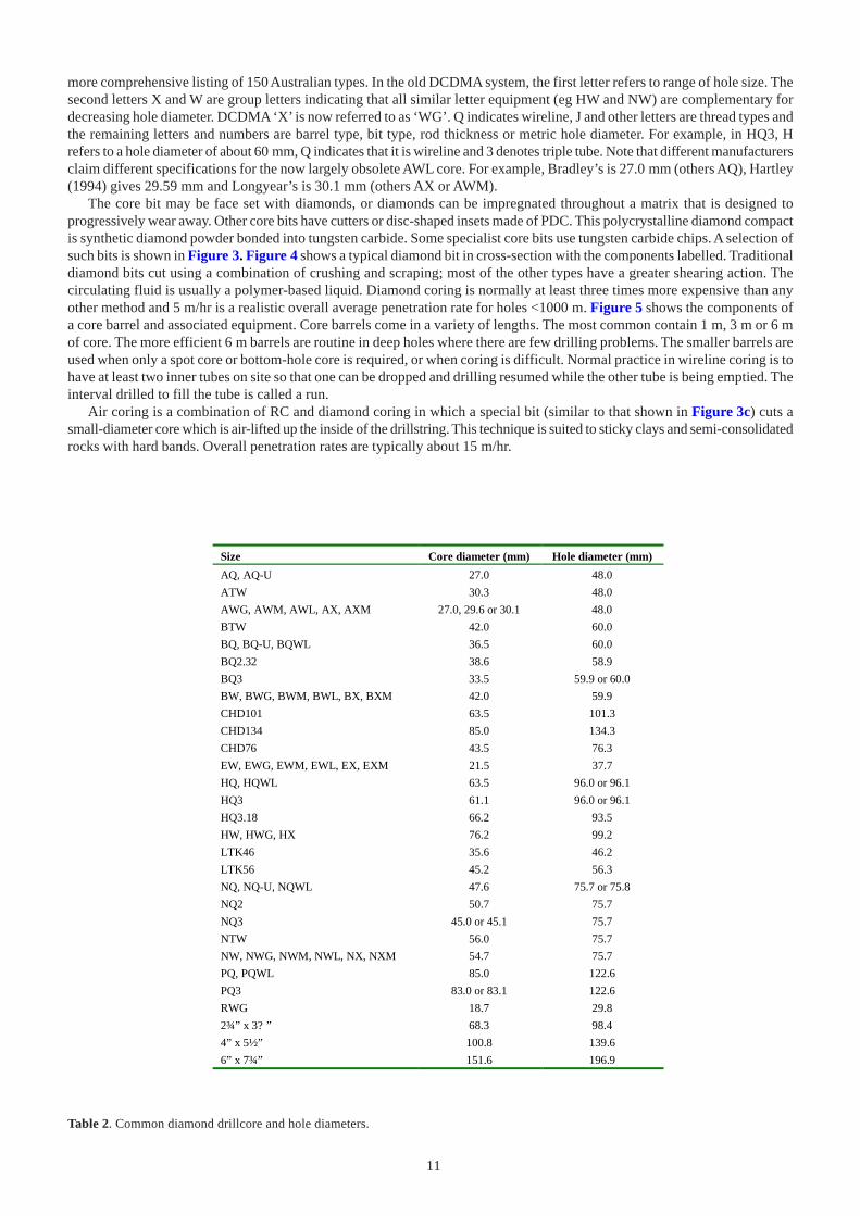
11
more comprehensive listing of 150 Australian types. In the old DCDMA system, the first letter refers to range of hole size. Thesecond letters X and W are group letters indicating that all similar letter equipment (eg HW and NW) are complementary fordecreasing hole diameter. DCDMA ‘X’ is now referred to as ‘WG’. Q indicates wireline, J and other letters are thread types andthe remaining letters and numbers are barrel type, bit type, rod thickness or metric hole diameter. For example, in HQ3, Hrefers to a hole diameter of about 60 mm, Q indicates that it is wireline and 3 denotes triple tube. Note that different manufacturersclaim different specifications for the now largely obsolete AWL core. For example, Bradley’s is 27.0 mm (others AQ), Hartley(1994) gives 29.59 mm and Longyear’s is 30.1 mm (others AX or AWM).
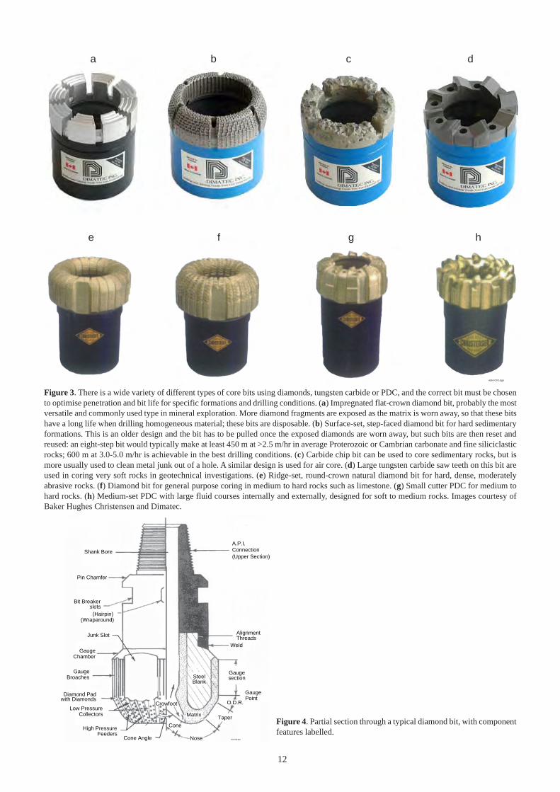
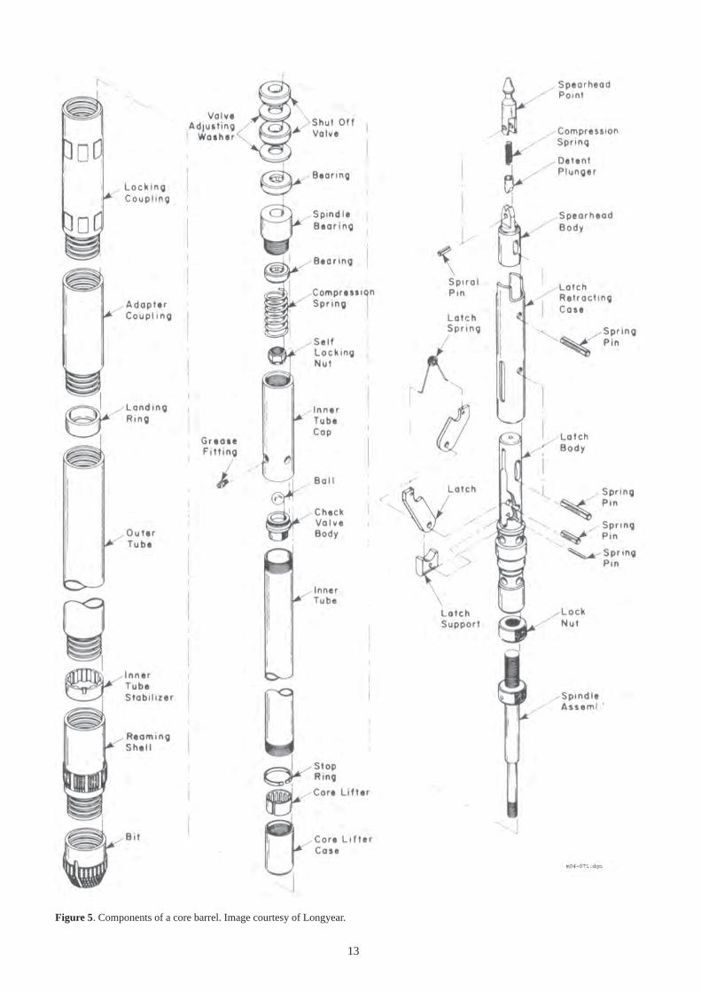
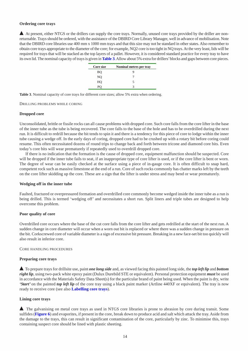
The core bit may be face set with diamonds, or diamonds can be impregnated throughout a matrix that is designed toprogressively wear away. Other core bits have cutters or disc-shaped insets made of PDC. This polycrystalline diamond compactis synthetic diamond powder bonded into tungsten carbide. Some specialist core bits use tungsten carbide chips. A selection ofsuch bits is shown in Figure 3. Figure 4 shows a typical diamond bit in cross-section with the components labelled. Traditionaldiamond bits cut using a combination of crushing and scraping; most of the other types have a greater shearing action. Thecirculating fluid is usually a polymer-based liquid. Diamond coring is normally at least three times more expensive than anyother method and 5 m/hr is a realistic overall average penetration rate for holes <1000 m. Figure 5 shows the components ofa core barrel and associated equipment. Core barrels come in a variety of lengths. The most common contain 1 m, 3 m or 6 mof core. The more efficient 6 m barrels are routine in deep holes where there are few drilling problems. The smaller barrels areused when only a spot core or bottom-hole core is required, or when coring is difficult. Normal practice in wireline coring is tohave at least two inner tubes on site so that one can be dropped and drilling resumed while the other tube is being emptied. Theinterval drilled to fill the tube is called a run.
Air coring is a combination of RC and diamond coring in which a special bit (similar to that shown in Figure 3c) cuts asmall-diameter core which is air-lifted up the inside of the drillstring. This technique is suited to sticky clays and semi-consolidatedrocks with hard bands. Overall penetration rates are typically about 15 m/hr.
Size Core diameter (mm) Hole diameter (mm)
AQ, AQ-U 27.0 48.0
ATW 30.3 48.0
AWG, AWM, AWL, AX, AXM 27.0, 29.6 or 30.1 48.0
BTW 42.0 60.0
BQ, BQ-U, BQWL 36.5 60.0
BQ2.32 38.6 58.9
BQ3 33.5 59.9 or 60.0
BW, BWG, BWM, BWL, BX, BXM 42.0 59.9
CHD101 63.5 101.3
CHD134 85.0 134.3
CHD76 43.5 76.3
EW, EWG, EWM, EWL, EX, EXM 21.5 37.7
HQ, HQWL 63.5 96.0 or 96.1
HQ3 61.1 96.0 or 96.1
HQ3.18 66.2 93.5
HW, HWG, HX 76.2 99.2
LTK46 35.6 46.2
LTK56 45.2 56.3
NQ, NQ-U, NQWL 47.6 75.7 or 75.8
NQ2 50.7 75.7
NQ3 45.0 or 45.1 75.7
NTW 56.0 75.7
NW, NWG, NWM, NWL, NX, NXM 54.7 75.7
PQ, PQWL 85.0 122.6
PQ3 83.0 or 83.1 122.6
RWG 18.7 29.8
2¾” x 3? ” 68.3 98.4
4” x 5½” 100.8 139.6
6” x 7¾” 151.6 196.9
Table 2. Common diamond drillcore and hole diameters.
12
a b c d
e f g h
m04-070.dgn
A.P.I.Connection(Upper Section)
AlignmentThreads
Weld
Gaugesection
O.D.R.
Taper
Nose
Cone
Shank Bore
Pin Chamfer
Bit Breakerslots(Hairpin)
(Wraparound)
Junk Slot
GaugeChamber
GaugeBroaches
Diamond Padwith Diamonds
Low PressureCollectors
High PressureFeeders
Cone Angle
SteelBlank
Crowfoot
Matrix
GaugePoint
m04-066.dgn
Figure 4. Partial section through a typical diamond bit, with componentfeatures labelled.
Figure 3. There is a wide variety of different types of core bits using diamonds, tungsten carbide or PDC, and the correct bit must be chosento optimise penetration and bit life for specific formations and drilling conditions. (a) Impregnated flat-crown diamond bit, probably the mostversatile and commonly used type in mineral exploration. More diamond fragments are exposed as the matrix is worn away, so that these bitshave a long life when drilling homogeneous material; these bits are disposable. (b) Surface-set, step-faced diamond bit for hard sedimentaryformations. This is an older design and the bit has to be pulled once the exposed diamonds are worn away, but such bits are then reset andreused: an eight-step bit would typically make at least 450 m at >2.5 m/hr in average Proterozoic or Cambrian carbonate and fine siliciclasticrocks; 600 m at 3.0-5.0 m/hr is achievable in the best drilling conditions. (c) Carbide chip bit can be used to core sedimentary rocks, but ismore usually used to clean metal junk out of a hole. A similar design is used for air core. (d) Large tungsten carbide saw teeth on this bit areused in coring very soft rocks in geotechnical investigations. (e) Ridge-set, round-crown natural diamond bit for hard, dense, moderatelyabrasive rocks. (f) Diamond bit for general purpose coring in medium to hard rocks such as limestone. (g) Small cutter PDC for medium tohard rocks. (h) Medium-set PDC with large fluid courses internally and externally, designed for soft to medium rocks. Images courtesy ofBaker Hughes Christensen and Dimatec.
13
Figure 5. Components of a core barrel. Image courtesy of Longyear.
14
Ordering core trays
% At present, either NTGS or the drillers can supply the core trays. Normally, unused core trays provided by the driller are non-returnable. Trays should be ordered, with the assistance of the DBIRD Core Library Manager, well in advance of mobilisation. Notethat the DBIRD core libraries use 400 mm x 1000 mm trays and that this size may not be standard in other states. Also remember toobtain core trays appropriate to the diameter of the core; for example, NQ2 core is too tight in NQ trays. At the very least, lids will berequired for trays that will be stacked as the top layers of a pallet. However, it is considered standard practice for every tray to haveits own lid. The nominal capacity of trays is given in Table 3. Allow about 5% extra for drillers’ blocks and gaps between core pieces.
Table 3. Nominal capacity of core trays for different core sizes; allow 5% extra when ordering.
Core size Nominal metres per tray
BQ 9
NQ 7
HQ 5
PQ 3
DRILLING PROBLEMS WHILE CORING
Dropped core
Unconsolidated, brittle or fissile rocks can all cause problems with dropped core. Such core falls from the core lifter in the baseof the inner tube as the tube is being recovered. The core falls to the base of the hole and has to be overdrilled during the nextrun. It is difficult to redrill because the bit tends to spin it and there is a tendency for this piece of core to lodge within the innertube causing a wedge off. In the early days of coring, dropped core had to be crushed up with a rotary bit before coring couldresume. This often necessitated dozens of round trips to change back and forth between tricone and diamond core bits. Eventoday’s core bits will wear prematurely if repeatedly used to overdrill dropped core.
If there is no indication that the formation is the cause of dropped core, equipment malfunction should be suspected. Corewill be dropped if the inner tube fails to seat, if an inappropriate type of core lifter is used, or if the core lifter is bent or worn.The degree of wear can be easily checked at the surface using a piece of in-gauge core. It is often difficult to snap hard,competent rock such as massive limestone at the end of a run. Core of such rocks commonly has chatter marks left by the teethon the core lifter skidding up the core. These are a sign that the lifter is under stress and may bend or wear prematurely.
Wedging off in the inner tube
Faulted, fractured or overpressured formation and overdrilled core commonly become wedged inside the inner tube as a run isbeing drilled. This is termed ‘wedging off’ and necessitates a short run. Split liners and triple tubes are designed to helpovercome this problem.
Poor quality of core
Overdrilled core occurs where the base of the cut core falls from the core lifter and gets redrilled at the start of the next run. Asudden change in core diameter will occur when a worn out bit is replaced or where there was a sudden change in pressure onthe bit. Corkscrewed core of variable diameter is a sign of excessive bit pressure. Breaking in a new face-set bit too quickly willalso result in inferior core.
CORE HANDLING PROCEDURES
Preparing core trays
% To prepare trays for drillsite use, paint one long side and, as viewed facing this painted long side, the top left lip and bottomright lip, using two-pack white epoxy paint (Dulux Durebild STE or equivalent). Personal protection equipment must be usedin accordance with the Materials Safety Data Sheet(s) for the particular brand of paint being used. When the paint is dry, write‘Start’ on the painted top left lip of the core tray using a black paint marker (Artline 440XF or equivalent). The tray is nowready to receive core (see also Labelling core trays).
Lining core trays
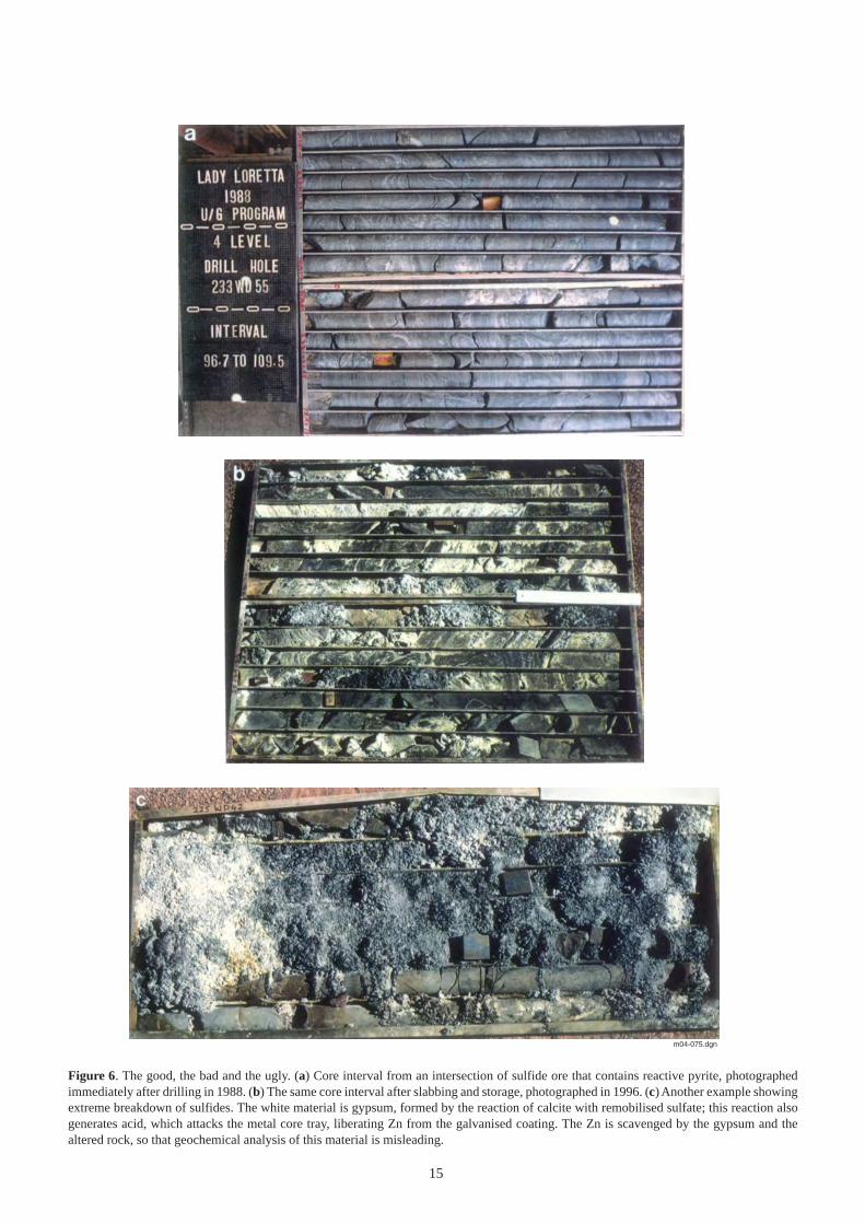
% The galvanising on metal core trays as used in NTGS core libraries is prone to abrasion by core during transit. Somesulfides (Figure 6) and evaporites, if present in the core, break down to produce acid and salt which attack the tray. Aside fromthe damage to the trays, this can result in significant contamination of the core, particularly by zinc. To minimise this, trayscontaining suspect core should be lined with plastic sheeting.
15
m04-075.dgn
Figure 6. The good, the bad and the ugly. (a) Core interval from an intersection of sulfide ore that contains reactive pyrite, photographedimmediately after drilling in 1988. (b) The same core interval after slabbing and storage, photographed in 1996. (c) Another example showingextreme breakdown of sulfides. The white material is gypsum, formed by the reaction of calcite with remobilised sulfate; this reaction alsogenerates acid, which attacks the metal core tray, liberating Zn from the galvanised coating. The Zn is scavenged by the gypsum and thealtered rock, so that geochemical analysis of this material is misleading.
16
Core catching
There are several methods whereby the driller can lay out therecovered core. In the petroleum industry, where everyconventional core costs tens of thousands of dollars, each corerun is laid out on a suitable rack (two lengths of pipe tied togetherover two 200 L drums are adequate). Normally the core isrecovered in a disposable liner which is cut away. There is nopossibility of getting pieces of core out of order or upside down.
Different practices are used during continuous coring in theminerals industry. If a spilt inner tube is used, the splits functionsimilarly to a liner and provide a platform for the core to beexamined and marked up. The core can then be slid directlyinto the core tray in the correct orientation.
Otherwise, when using a conventional barrel, normal practice is for the driller’s assistant to deposit the core directly intothe trays while the tube is still suspended by the wireline. This is fraught with problems and is not recommended. Firstly, thecore comes out of the tube bottom first, so the assistant has to judge how far into the empty tray to begin depositing the core.It is normally necessary to hammer the core lifter with a rubber mallet to free the lowermost piece of core protruding from thetube. This invariably flies off and has to be reoriented. Once freed, careful coordination is necessary to prevent the remainingcore falling uncontrolled from the tube. The driller has to feed out the wireline from the winch and the assistant move the tubealong the segments of the trays while keeping the lower end of the tube close enough to the tray to prevent core spilling out. Ifthe core is recovered in long solid sticks, the assistant has to juggle the tube while using a hammer to break the core at the startof the next core box segment. Not only does this risk misorienting core but it is potentially dangerous (see Safety note). Mostdrillers have a tendency to overfill each segment of the tray, making it difficult to get the core out again.
% Preferably, when using a conventional barrel, onsite NTGS staff should ensure that core is deposited onto a suitablerack for marking up and is then transferred from there to the trays by a trained NTGS Technical Assistant. If – and only if– this is not feasible, core may be dumped directly into trays. Drillers should be closely supervised during this procedure foreach and every run. (This is one of the reasons for NTGS to maintain a technically competent presence on site during drilling).Edge matching and marking-up of the trayed core will then need to be done, metre by metre.
Irrespective of barrel type, NTGS practice is to load core trays from the top left (‘Start’), so that contained core runscontinuously from shallowest at top left to deepest at bottom right when viewed facing the painted long side of the tray.
Edge matching, washing and core orientation lines
A standard convention of marking the core longitudinally:
• Enables broken edges to be easily rematched (between and within runs), ensuring accurate recovery measurements• Provides a datum for relative measurement of sedimentary features and metamorphic fabrics (eg relative directions of
crossbeds, orientation of cleavage)• Means that large sections of the core are already oriented when an absolute determination of orientation is undertaken (see
Determining absolute core orientation and measuring true dip and strike)• Ensures that composite sampling of core is consistent relative to a longitudinal frame of reference• Ensures that core can never be returned to the tray upside down
% The last piece of marked core from the previous run should be left on the core rack or near where the core is being examinedin the boxes. Immediately after removal from the inner tube the new core should be laid out starting with the bottom piece fromthe previous run, so that all the ends are matched. The new core is then washed. A nylon brush may be used but cloth is to beavoided since lint fluoresces under UV light. Once dry, the core can be marked up. If there is no apparent fit between adjacentpieces and it is certain that pieces of core have been laid out in the correct order, two arrow-up chevrons are marked on eitherside of the cores that do not match. All core is to be marked with permanent continuous longitudinal orientation lines usingthe AAPG standard of black line on the right, red line on the left when core is viewed in correct orientation (but see Sealingoil-soaked core). Two marking pens taped together are used (Figure 7b). The tips of the marking pens will wear rapidly, so besure to have adequate supplies. Chisel-tipped pens last longest.
Labelling driller’s blocks
% The drilling Contractor should label driller’s blocks with end-of-run metreage (Figure 7c), depth of change in core diameter,absolute orientation points and end-of-hole metreage. Be sure that it is clear in the contract as to who is supplying the blocks.Wooden blocks or plastic markers are acceptable. The latter have the disadvantages that they must be the exact width for thecore tray and are easily dislodged by hosing the core or if open trays are left out in high winds. An approved permanent markingpen is to be used. Alternatively, inscribed aluminium tags can be stapled to the wooden block. All labels are to be oriented to
Safety noteOn no account is anyone to hold their hand under theend of the inner tube or put their fingers up the end of thetube at any time. Safety glasses must be worn if the core isbeing broken.The inner tube of a triple tube system should be pumpedout using liquid, never air. An appropriate bumper must beplaced at the bottom of the tube to prevent core flying outunder pressure and noone is to stand within 5 m of the tubewhile pumping is in progress.
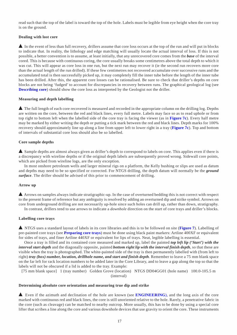
17
read such that the top of the label is toward the top of the hole. Labels must be legible from eye height when the core trayis on the ground.
Dealing with lost core
% In the event of less than full recovery, drillers assume that core loss occurs at the top of the run and will put in blocksto indicate that. In reality, the lithology and edge matching will usually locate the actual interval of loss. If this is notpossible, a better convention is to assume, at least initially, that any unrecovered core comes from the base of the intervalcored. This is because with continuous coring, the core usually breaks some centimetres above the total depth to which itwas cut. This will appear as core loss in one run, but the next run may recover it (ie the second run recovers more corethan the actual length of the run drilled). If these few centimetres not recovered accumulate over successive runs and theaccumulated total is then successfully picked up, it may completely fill the inner tube before the length of the inner tubehas been drilled. After this, the apparent core losses can be rationalised. Be sure to check that driller’s depths on coreblocks are not being ‘fudged’ to account for discrepancies in recovery between runs. The graphical geological log (seeDescribing core) should show the core loss as interpreted by the Geologist not the driller.
Measuring and depth labelling
% The full length of each core recovered is measured and recorded in the appropriate column on the drilling log. Depthsare written on the core, between the red and black lines, every full metre. Labels may face so as to read uphole or fromtop right to bottom left when the labelled side of the core tray is facing the viewer (as in Figure 7c). Every half metremay be marked by either writing the depth or putting a tick mark between the red and black lines. Depth marks for 100%recovery should approximately line up along a line from upper left to lower right in a tray (Figure 7c). Top and bottomof intervals of substantial core loss should also be so labelled.
Core sample depths
% Sample depths are almost always given as driller’s depth to correspond to labels on core. This applies even if there isa discrepancy with wireline depths or if the original depth labels are subsequently proved wrong. Sidewall core points,which are picked from wireline logs, are the only exception.
In most onshore petroleum wells and larger mineral rigs on a platform, the Kelly bushing or slips are used as datumand depths may need to be so specified or corrected. For NTGS drilling, the depth datum will normally be the groundsurface. The driller should be advised of this prior to commencement of drilling.
Arrow up
% Arrows on samples always indicate stratigraphic-up. In the case of overturned bedding this is not correct with respectto the present frame of reference but any ambiguity is resolved by adding an overturned dip and strike symbol. Arrows oncore from underground drilling are not necessarily up-hole since such holes can drill up, rather than down, stratigraphy.
In contrast, drillers tend to use arrows to indicate a downhole direction on the start of core trays and driller’s blocks.
Labelling core trays
% NTGS uses a standard layout of labels in its core libraries and this is to be followed on site (Figure 7). Labelling ofpre-painted core trays (see Preparing core trays) must be done using black paint markers: Artline 400XF or equivalentfor sides of trays, and finer Artline 440XF or equivalent for lips of trays. Neat, legible labelling is essential.
Once a tray is filled and its contained core measured and marked up, label the painted top left lip (‘Start’) with theinterval start depth and the diagonally opposite, painted bottom right lip with the interval finish depth, so that these arevisible when the tray is photographed. The white-painted side of the tray is then permanently labelled with (from left toright) tray (box) number, location, drillhole name, and start and finish depth. Remember to leave a 75 mm blank spaceon the far left for rack location numbers to be added later in the Core Library, and to leave a gap along the top so that thelabels will not be obscured if a lid is added to the tray. Example:
[75 mm blank space] 1 (tray number) Golden Grove (location) NTGS DD04GG01 (hole name) 100.0-105.5 m(interval)
Determining absolute core orientation and measuring true dip and strike
% Even if the azimuth and declination of the hole are known (see ENGINEERING), and the long axis of the coremarked with continuous red and black lines, the core is still unoriented relative to the hole. Rarely, a penetrative fabric inthe core (such as cleavage) can be matched to nearby outcrop. More usually, this has to be done by using a special corelifter that scribes a line along the core and various downhole devices that use gravity to orient the core. These instruments
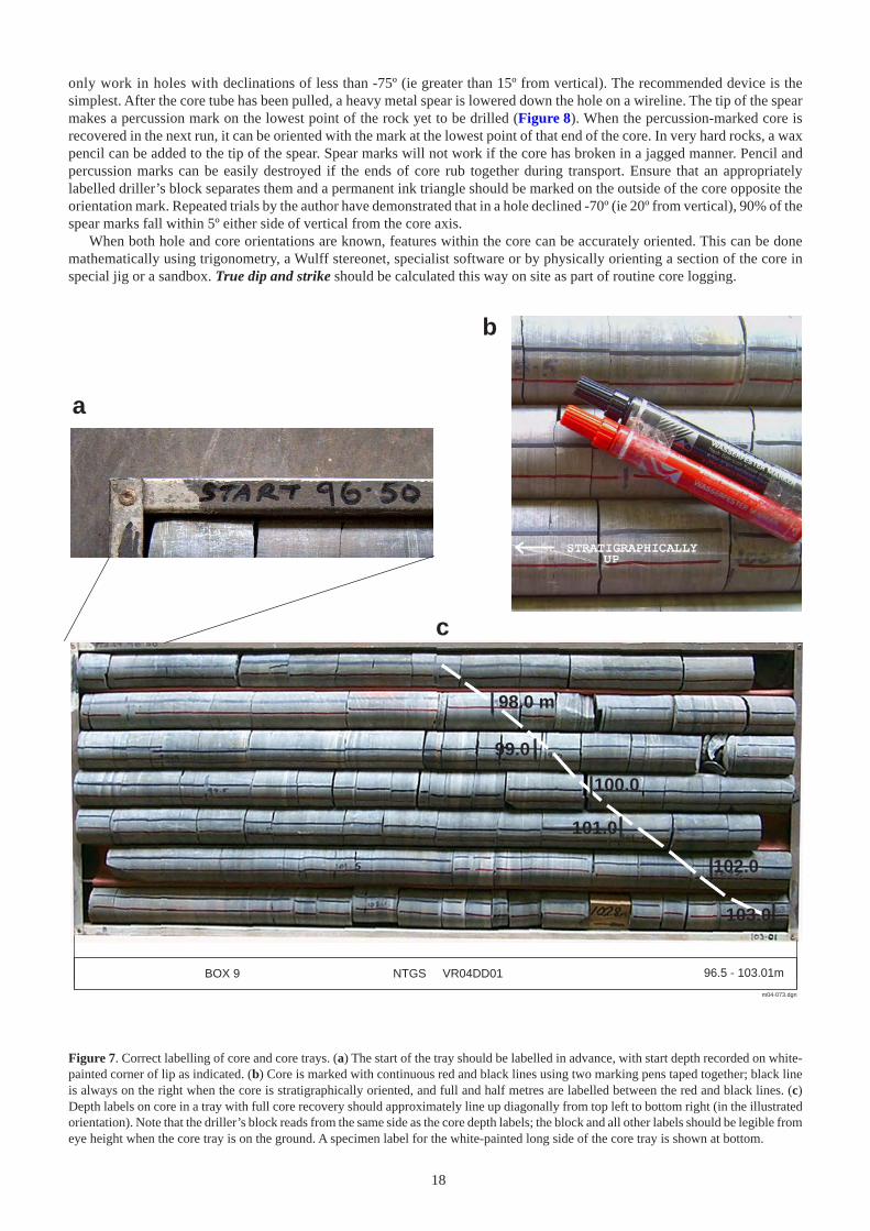
18
only work in holes with declinations of less than -75º (ie greater than 15º from vertical). The recommended device is thesimplest. After the core tube has been pulled, a heavy metal spear is lowered down the hole on a wireline. The tip of the spearmakes a percussion mark on the lowest point of the rock yet to be drilled (Figure 8). When the percussion-marked core isrecovered in the next run, it can be oriented with the mark at the lowest point of that end of the core. In very hard rocks, a waxpencil can be added to the tip of the spear. Spear marks will not work if the core has broken in a jagged manner. Pencil andpercussion marks can be easily destroyed if the ends of core rub together during transport. Ensure that an appropriatelylabelled driller’s block separates them and a permanent ink triangle should be marked on the outside of the core opposite theorientation mark. Repeated trials by the author have demonstrated that in a hole declined -70º (ie 20º from vertical), 90% of thespear marks fall within 5º either side of vertical from the core axis.
When both hole and core orientations are known, features within the core can be accurately oriented. This can be donemathematically using trigonometry, a Wulff stereonet, specialist software or by physically orienting a section of the core inspecial jig or a sandbox. True dip and strike should be calculated this way on site as part of routine core logging.
m04-073.dgn
BOX 9 96.5 - 103.01m
a
b
c
98.0 m
99.0
101.0
102.0
103.0
100.0
NTGS VR04DD01
Figure 7. Correct labelling of core and core trays. (a) The start of the tray should be labelled in advance, with start depth recorded on white-painted corner of lip as indicated. (b) Core is marked with continuous red and black lines using two marking pens taped together; black lineis always on the right when the core is stratigraphically oriented, and full and half metres are labelled between the red and black lines. (c)Depth labels on core in a tray with full core recovery should approximately line up diagonally from top left to bottom right (in the illustratedorientation). Note that the driller’s block reads from the same side as the core depth labels; the block and all other labels should be legible fromeye height when the core tray is on the ground. A specimen label for the white-painted long side of the core tray is shown at bottom.
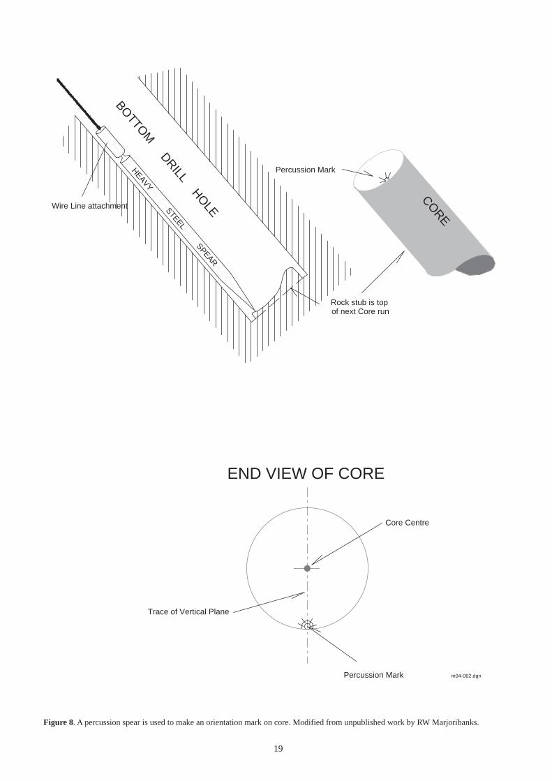
19
m04-062.dgn
HEAVY
STEEL
SPEAR
BOTTO
M DRILL HO
LEWire Line attachment
Rock stub is top of next Core run
Percussion Mark
END VIEW OF CORE
Percussion Mark
Core Centre
Trace of Vertical Plane
CORE
Figure 8. A percussion spear is used to make an orientation mark on core. Modified from unpublished work by RW Marjoribanks.
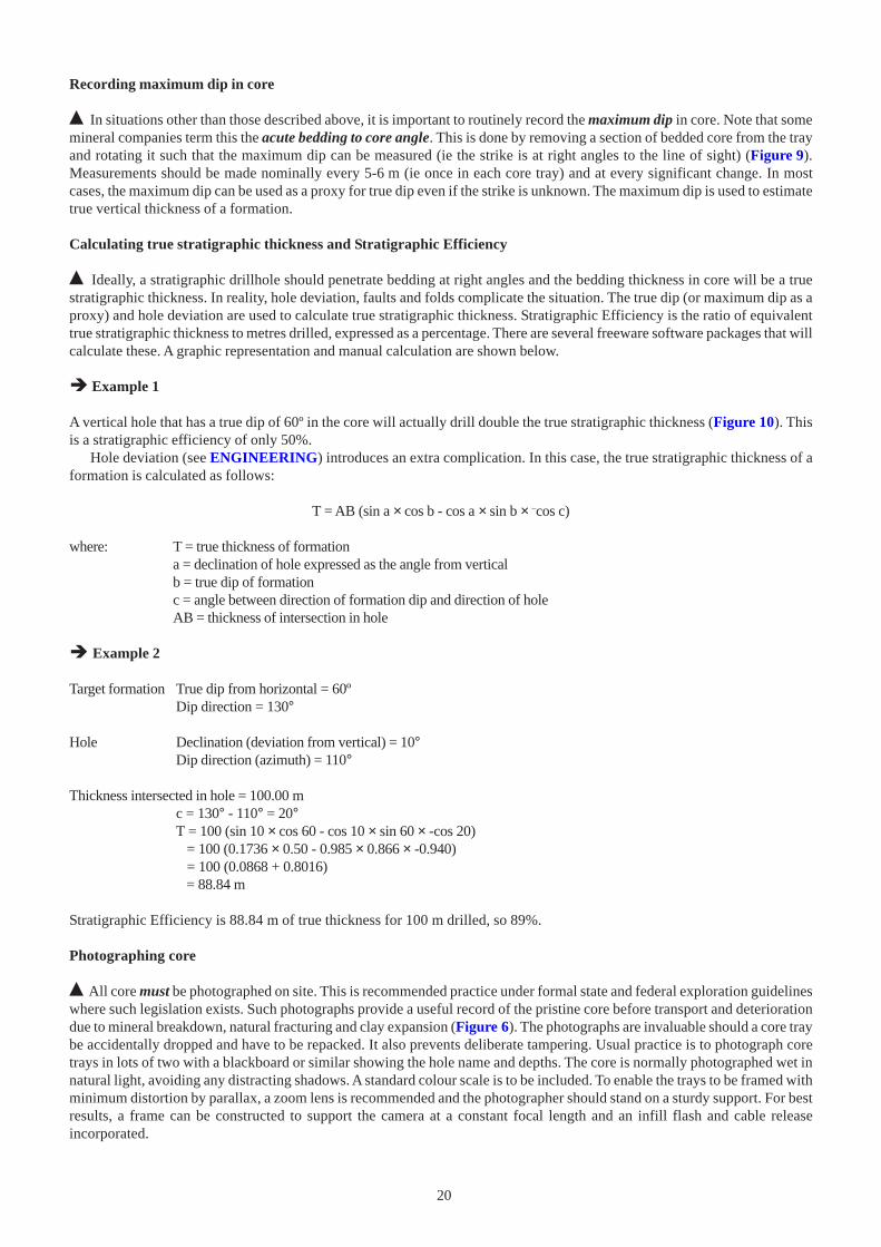
20
Recording maximum dip in core
% In situations other than those described above, it is important to routinely record the maximum dip in core. Note that somemineral companies term this the acute bedding to core angle. This is done by removing a section of bedded core from the trayand rotating it such that the maximum dip can be measured (ie the strike is at right angles to the line of sight) (Figure 9).Measurements should be made nominally every 5-6 m (ie once in each core tray) and at every significant change. In mostcases, the maximum dip can be used as a proxy for true dip even if the strike is unknown. The maximum dip is used to estimatetrue vertical thickness of a formation.
Calculating true stratigraphic thickness and Stratigraphic Efficiency
% Ideally, a stratigraphic drillhole should penetrate bedding at right angles and the bedding thickness in core will be a truestratigraphic thickness. In reality, hole deviation, faults and folds complicate the situation. The true dip (or maximum dip as aproxy) and hole deviation are used to calculate true stratigraphic thickness. Stratigraphic Efficiency is the ratio of equivalenttrue stratigraphic thickness to metres drilled, expressed as a percentage. There are several freeware software packages that willcalculate these. A graphic representation and manual calculation are shown below.
� Example 1
A vertical hole that has a true dip of 60º in the core will actually drill double the true stratigraphic thickness (Figure 10). Thisis a stratigraphic efficiency of only 50%.
Hole deviation (see ENGINEERING) introduces an extra complication. In this case, the true stratigraphic thickness of aformation is calculated as follows:
T = AB (sin a × cos b - cos a × sin b × –cos c)
where: T = true thickness of formationa = declination of hole expressed as the angle from verticalb = true dip of formationc = angle between direction of formation dip and direction of holeAB = thickness of intersection in hole
� Example 2
Target formation True dip from horizontal = 60ºDip direction = 130°
Hole Declination (deviation from vertical) = 10°Dip direction (azimuth) = 110°
Thickness intersected in hole = 100.00 mc = 130° - 110° = 20°T = 100 (sin 10 × cos 60 - cos 10 × sin 60 × -cos 20) = 100 (0.1736 × 0.50 - 0.985 × 0.866 × -0.940) = 100 (0.0868 + 0.8016) = 88.84 m
Stratigraphic Efficiency is 88.84 m of true thickness for 100 m drilled, so 89%.
Photographing core
% All core must be photographed on site. This is recommended practice under formal state and federal exploration guidelineswhere such legislation exists. Such photographs provide a useful record of the pristine core before transport and deteriorationdue to mineral breakdown, natural fracturing and clay expansion (Figure 6). The photographs are invaluable should a core traybe accidentally dropped and have to be repacked. It also prevents deliberate tampering. Usual practice is to photograph coretrays in lots of two with a blackboard or similar showing the hole name and depths. The core is normally photographed wet innatural light, avoiding any distracting shadows. A standard colour scale is to be included. To enable the trays to be framed withminimum distortion by parallax, a zoom lens is recommended and the photographer should stand on a sturdy support. For bestresults, a frame can be constructed to support the camera at a constant focal length and an infill flash and cable releaseincorporated.
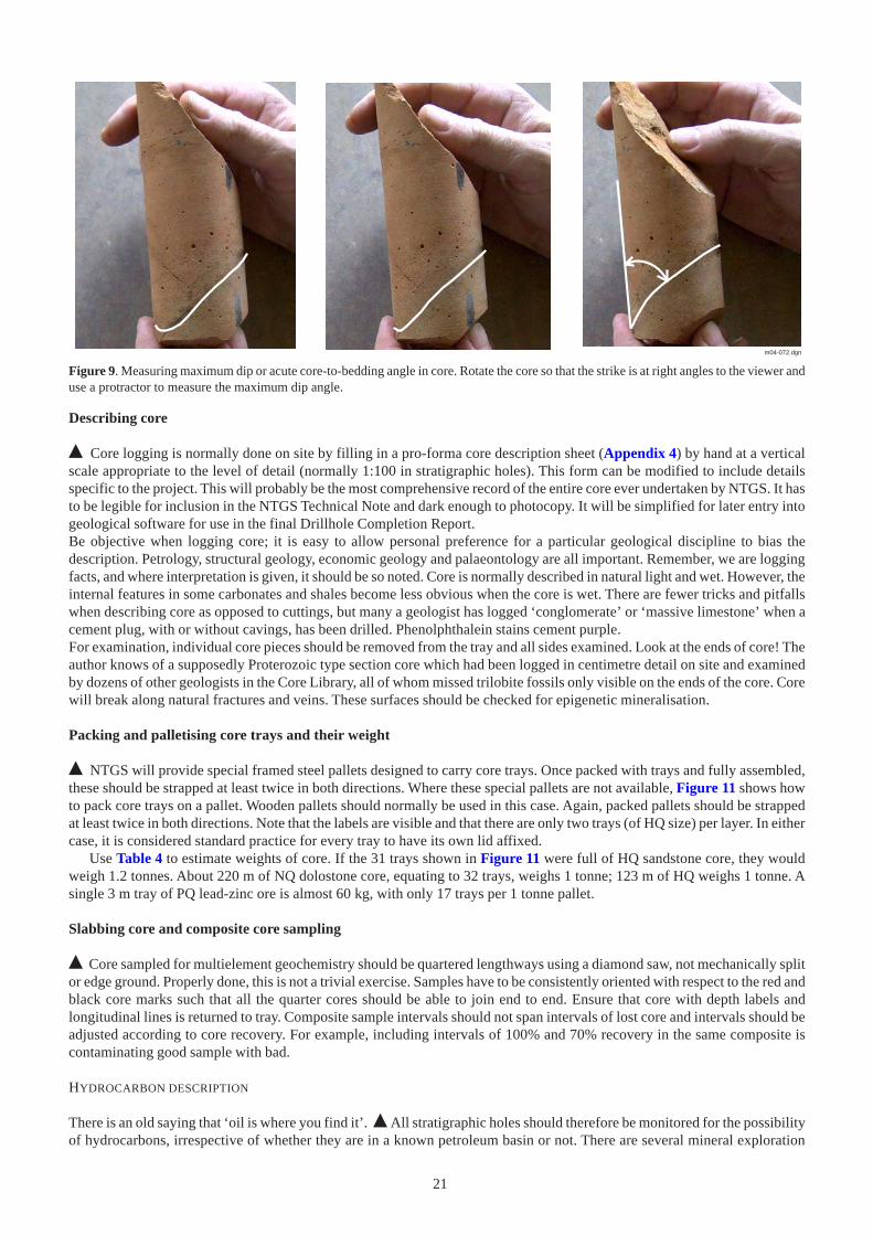
21
m04-072.dgn
Figure 9. Measuring maximum dip or acute core-to-bedding angle in core. Rotate the core so that the strike is at right angles to the viewer anduse a protractor to measure the maximum dip angle.
Describing core
% Core logging is normally done on site by filling in a pro-forma core description sheet (Appendix 4) by hand at a verticalscale appropriate to the level of detail (normally 1:100 in stratigraphic holes). This form can be modified to include detailsspecific to the project. This will probably be the most comprehensive record of the entire core ever undertaken by NTGS. It hasto be legible for inclusion in the NTGS Technical Note and dark enough to photocopy. It will be simplified for later entry intogeological software for use in the final Drillhole Completion Report.Be objective when logging core; it is easy to allow personal preference for a particular geological discipline to bias thedescription. Petrology, structural geology, economic geology and palaeontology are all important. Remember, we are loggingfacts, and where interpretation is given, it should be so noted. Core is normally described in natural light and wet. However, theinternal features in some carbonates and shales become less obvious when the core is wet. There are fewer tricks and pitfallswhen describing core as opposed to cuttings, but many a geologist has logged ‘conglomerate’ or ‘massive limestone’ when acement plug, with or without cavings, has been drilled. Phenolphthalein stains cement purple.For examination, individual core pieces should be removed from the tray and all sides examined. Look at the ends of core! Theauthor knows of a supposedly Proterozoic type section core which had been logged in centimetre detail on site and examinedby dozens of other geologists in the Core Library, all of whom missed trilobite fossils only visible on the ends of the core. Corewill break along natural fractures and veins. These surfaces should be checked for epigenetic mineralisation.
Packing and palletising core trays and their weight
% NTGS will provide special framed steel pallets designed to carry core trays. Once packed with trays and fully assembled,these should be strapped at least twice in both directions. Where these special pallets are not available, Figure 11 shows howto pack core trays on a pallet. Wooden pallets should normally be used in this case. Again, packed pallets should be strappedat least twice in both directions. Note that the labels are visible and that there are only two trays (of HQ size) per layer. In eithercase, it is considered standard practice for every tray to have its own lid affixed.
Use Table 4 to estimate weights of core. If the 31 trays shown in Figure 11 were full of HQ sandstone core, they wouldweigh 1.2 tonnes. About 220 m of NQ dolostone core, equating to 32 trays, weighs 1 tonne; 123 m of HQ weighs 1 tonne. Asingle 3 m tray of PQ lead-zinc ore is almost 60 kg, with only 17 trays per 1 tonne pallet.
Slabbing core and composite core sampling
% Core sampled for multielement geochemistry should be quartered lengthways using a diamond saw, not mechanically splitor edge ground. Properly done, this is not a trivial exercise. Samples have to be consistently oriented with respect to the red andblack core marks such that all the quarter cores should be able to join end to end. Ensure that core with depth labels andlongitudinal lines is returned to tray. Composite sample intervals should not span intervals of lost core and intervals should beadjusted according to core recovery. For example, including intervals of 100% and 70% recovery in the same composite iscontaminating good sample with bad.
HYDROCARBON DESCRIPTION
There is an old saying that ‘oil is where you find it’. % All stratigraphic holes should therefore be monitored for the possibilityof hydrocarbons, irrespective of whether they are in a known petroleum basin or not. There are several mineral exploration
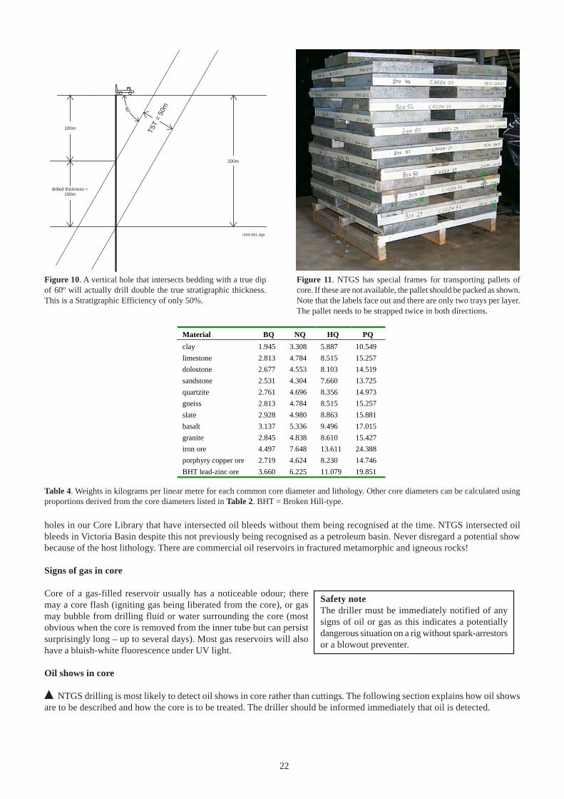
22
m04-061.dgn
100m
200m
100m
TST
= 50
m60°
drilled thickness =
Figure 10. A vertical hole that intersects bedding with a true dipof 60º will actually drill double the true stratigraphic thickness.This is a Stratigraphic Efficiency of only 50%.
Figure 11. NTGS has special frames for transporting pallets ofcore. If these are not available, the pallet should be packed as shown.Note that the labels face out and there are only two trays per layer.The pallet needs to be strapped twice in both directions.
Safety noteThe driller must be immediately notified of anysigns of oil or gas as this indicates a potentiallydangerous situation on a rig without spark-arrestorsor a blowout preventer.
Table 4. Weights in kilograms per linear metre for each common core diameter and lithology. Other core diameters can be calculated usingproportions derived from the core diameters listed in Table 2. BHT = Broken Hill-type.
Material BQ NQ HQ PQ
clay 1.945 3.308 5.887 10.549
limestone 2.813 4.784 8.515 15.257
dolostone 2.677 4.553 8.103 14.519
sandstone 2.531 4.304 7.660 13.725
quartzite 2.761 4.696 8.356 14.973
gneiss 2.813 4.784 8.515 15.257
slate 2.928 4.980 8.863 15.881
basalt 3.137 5.336 9.496 17.015
granite 2.845 4.838 8.610 15.427
iron ore 4.497 7.648 13.611 24.388
porphyry copper ore 2.719 4.624 8.230 14.746
BHT lead-zinc ore 3.660 6.225 11.079 19.851
holes in our Core Library that have intersected oil bleeds without them being recognised at the time. NTGS intersected oilbleeds in Victoria Basin despite this not previously being recognised as a petroleum basin. Never disregard a potential showbecause of the host lithology. There are commercial oil reservoirs in fractured metamorphic and igneous rocks!
Signs of gas in core
Core of a gas-filled reservoir usually has a noticeable odour; theremay a core flash (igniting gas being liberated from the core), or gasmay bubble from drilling fluid or water surrounding the core (mostobvious when the core is removed from the inner tube but can persistsurprisingly long – up to several days). Most gas reservoirs will alsohave a bluish-white fluorescence under UV light.
Oil shows in core
% NTGS drilling is most likely to detect oil shows in core rather than cuttings. The following section explains how oil showsare to be described and how the core is to be treated. The driller should be informed immediately that oil is detected.
23
Oil bleeds
Most oil bleeds are obvious to the naked eye and have a distinctive odour. In natural light, oil can range in colour from opaquevery dark brown to colourless. Figure 12 shows typical oil bleeds from Cambrian rocks. Light oil is usually first detected in thedrilling fluid surrounding the core by iridescence and surface tension affects. In tight reservoirs, even light oil bleeds may notappear until minutes or hours after the drilling fluid is wiped off. Such phenomena should be fully described, such as ‘strawcoloured live oil bleeding from hairline fracture at 456.8 m; first appeared 15 minutes after core removed from inner tube’.Very light oil may dissipate even before the core is removed from the inner tube. Heavy oil is less mobile.
Sealing oil-soaked core
Core with significant live oil must be sealed to help prevent loss of volatiles and biodegradation. This involves wrapping thesection of core in aluminium foil, several layers of plastic cling film and a final wrapping of aluminium foil held in place withmasking tape. Do not write directly on the core with marker pens – this may compromise any subsequent organic geochemicalanalyses. The masking tape is marked with the ubiquitous red and black lines and labelled with drillhole and depth. On apetroleum rig, these samples are than sealed by dipping in molten wax. Samples that contain live oil should be stored in a coolplace.
Fluorescence
Benzol rings in a hydrocarbon cause it to fluoresce under UV light and a suitable lamp should be on site for all potentiallyprospective holes. Three types of UV lights designed for use with hydrocarbons are available: a high-intensity hand-held UVlight, a box-mounted fluoroscope (also known as a viewing cabinet) and a corvascope (combination stereoscopic zoom micro-scope and UV light). These operate in the range of 350-400 �m, nominally 365 �m, ideally with an intensity of ≥850 uw/cm2.Hand-held UV lamps designed for mineral prospecting come in various combinations of short (254 �m = 2537 Angstrom),medium (302 �m) and long (365 �m) wavelengths. All will make hydrocarbons fluoresce, but the longest wavelength iscomparable with those designed for petroleum exploration. Most mineral prospecting lamps are of such low intensity that allother background illumination has to be excluded. When using this method to examine core, it may be necessary to work atnight or under a blanket. Alternatively, a ‘darkroom’ viewingcabinet can be used. Areas of fluorescence are marked withchalk (not a solvent-based marking pen) so that they can berelocated under natural light.Colours of hydrocarbon fluorescence include green, gold,orange, yellow, blue, blue-white or white. This colour rangebroadly corresponds to heavy through to light oils. Oils of 35-45 API gravity fluoresce white to blue-white. Intensity is describedas bright, dull, pale or faint. Figure 13 shows typical oil-stainedcore in UV light. Very heavy biodegraded oil may not fluorescein its natural state, but will after solvent extraction (see Cut andsolvent tests). Very light condensates may fluoresce beyond thehuman visible spectrum. Be wary of mineral fluorescence; calciteand dolomite can both fluoresce blue-white, brown or red. Mostgreases and many other contaminants fluoresce (seeContamination).
Cut and solvent tests
A ‘crush cut’ is the solvent extraction of hydrocarbons from acrushed rock sample. Fluorescing cuttings or core chips are handpicked and placed in a white porcelain dish (spot dish) and a fewdrops of solvent added. Any hydrocarbons present will dissolveand sometimes oil may be seen moving into the solvent even innatural light. This is termed a ‘streaming cut’. This phenomenonis best observed under UV light. In less than a minute, the cutwill impart a fluorescence to the solvent. As the solvent evaporates,a residual ring of fluorescence is left in the spot dish. The solventis also added to an identical spot dish without any cuttings. Thisblind test, which should of course not fluoresce, checks forcontamination in the solvent. It is also prudent to set up standardsof all the possible contaminants on site.
Safety noteVarious solvents have been used for rig-site hydrocarbondetection. Those recommended in older manuals have beenphased out because of health or environmental concerns.Toluene, a common ingredient in petrol (up to 13% toluene),glue and paint thinners, is currently the preferred choice.Toluene is variously known as C7H8, methylbenzene,methylbenzol, Methacide, phenylmethane, Toluol and Antisal1A. Its international CAS Registry Number is 108-88-3.Absorption through the skin or exposure to its vapour ispotentially dangerous. It can damage the nervous system andcause an irregular heartbeat. Workers with a history of asthmainduced by solvent exposure should be warned. You can smelltoluene when it reaches 290 ppb and it is considered safe towork in levels up to 100 ppm. The Occupational Safety andHealth Administration has set a limit of 200 ppm of workplaceair (690 times the detectable limit in humans). Toluene isheavier than air. Both liquid and vapour are flammable.Contact with strong oxidisers may cause fire or explosion.The liquid can accumulate static charge by flow or agitation.It should not be carried on aircraft. Proprietary detergent-based substitutes (eg Sample Clean) are also available butcan be difficult to source.
Safety noteUV light will harm your eyes. Shorter wavelengths are themore dangerous. Do not look directly into a source of UVlight and avoid working for more than 15 minutes at a timewith reflected UV light. Normal eye glasses or transparentsafety glasses will reduce UV exposure.
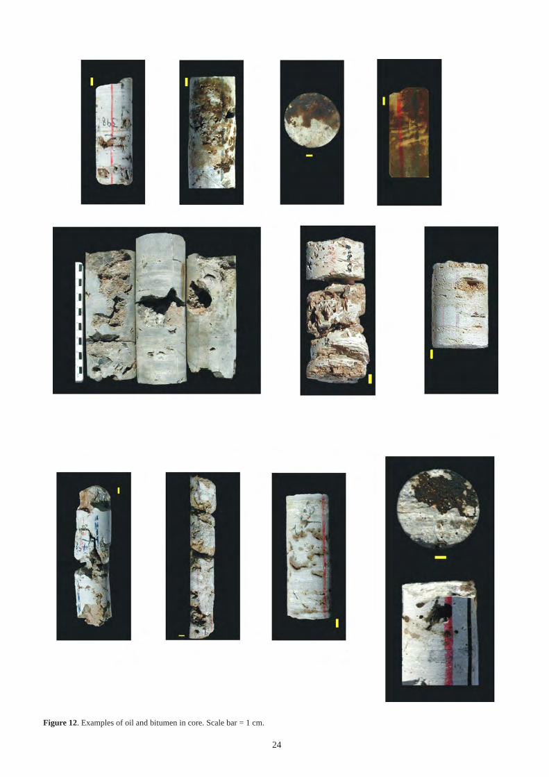
24
Figure 12. Examples of oil and bitumen in core. Scale bar = 1 cm.
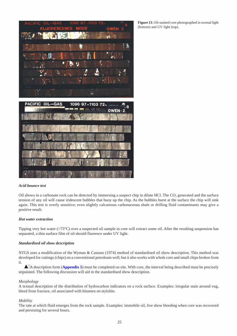
25
Acid bounce test
Oil shows in a carbonate rock can be detected by immersing a suspect chip in dilute HCl. The CO2 generated and the surfacetension of any oil will cause iridescent bubbles that buoy up the chip. As the bubbles burst at the surface the chip will sinkagain. This test is overly sensitive; even slightly calcareous carbonaceous shale or drilling fluid contaminants may give apositive result.
Hot water extraction
Tipping very hot water (>75°C) over a suspected oil sample in core will extract some oil. After the resulting suspension hasseparated, a thin surface film of oil should fluoresce under UV light.
Standardised oil show description
NTGS uses a modification of the Wyman & Castano (1974) method of standardised oil show description. This method wasdeveloped for cuttings (chips) on a conventional petroleum well; but it also works with whole core and small chips broken fromit.
% A description form (Appendix 5) must be completed on site. With core, the interval being described must be preciselystipulated. The following discussion will aid in the standardised show description.
MorphologyA textual description of the distribution of hydrocarbon indicators on a rock surface. Examples: irregular stain around vug,bleed from fracture, oil associated with bitumen on stylolite.
MobilityThe rate at which fluid emerges from the rock sample. Examples: immobile oil, live show bleeding when core was recoveredand persisting for several hours.
Figure 13. Oil-stained core photographed in normal light(bottom) and UV light (top).
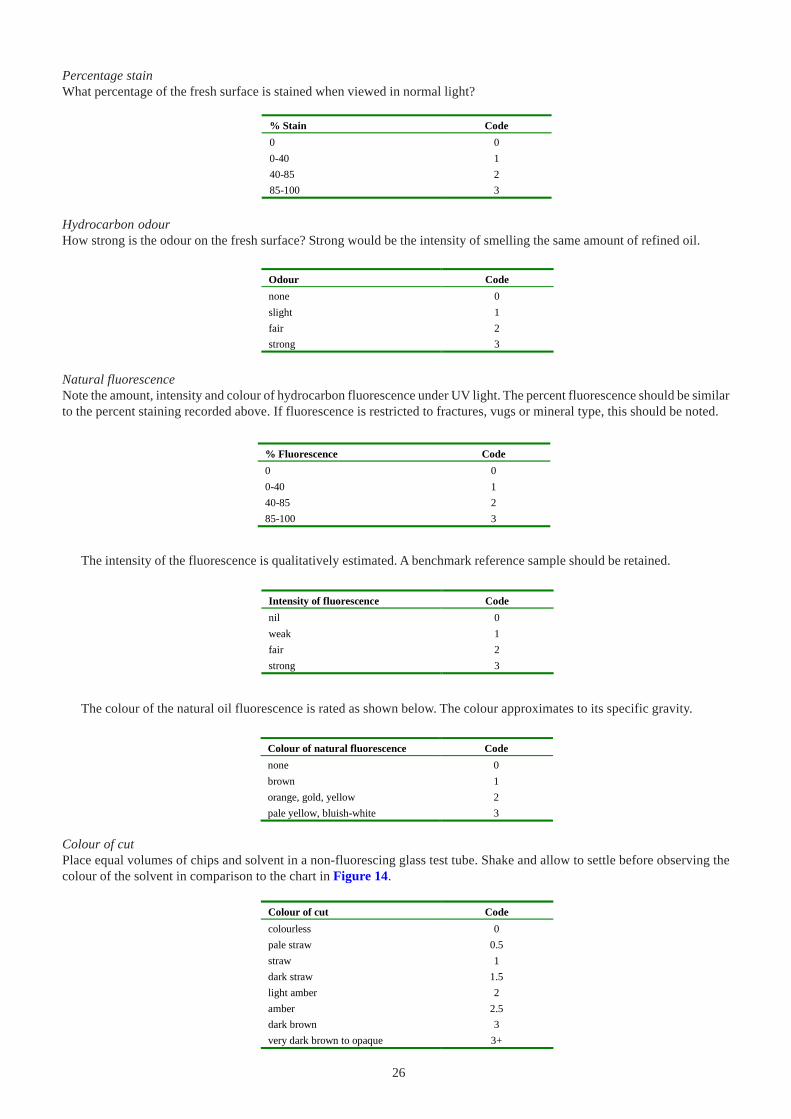
26
% Stain Code
0 0
0-40 1
40-85 2
85-100 3
Odour Code
none 0
slight 1
fair 2
strong 3
% Fluorescence Code
0 0
0-40 1
40-85 2
85-100 3
Hydrocarbon odourHow strong is the odour on the fresh surface? Strong would be the intensity of smelling the same amount of refined oil.
Natural fluorescenceNote the amount, intensity and colour of hydrocarbon fluorescence under UV light. The percent fluorescence should be similarto the percent staining recorded above. If fluorescence is restricted to fractures, vugs or mineral type, this should be noted.
Intensity of fluorescence Code
nil 0
weak 1
fair 2
strong 3
The intensity of the fluorescence is qualitatively estimated. A benchmark reference sample should be retained.
The colour of the natural oil fluorescence is rated as shown below. The colour approximates to its specific gravity.
Colour of natural fluorescence Code
none 0
brown 1
orange, gold, yellow 2
pale yellow, bluish-white 3
Colour of cut
Place equal volumes of chips and solvent in a non-fluorescing glass test tube. Shake and allow to settle before observing thecolour of the solvent in comparison to the chart in Figure 14.
Colour of cut Code
colourless 0
pale straw 0.5
straw 1
dark straw 1.5
light amber 2
amber 2.5
dark brown 3
very dark brown to opaque 3+
Percentage stainWhat percentage of the fresh surface is stained when viewed in normal light?
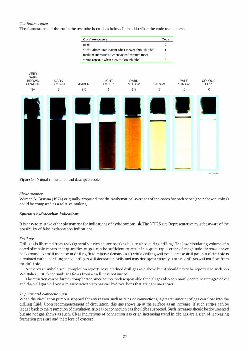
27
Show numberWyman & Castano (1974) originally proposed that the mathematical averages of the codes for each show (their show number)could be compared as a relative ranking.
Spurious hydrocarbon indications
It is easy to mistake other phenomena for indications of hydrocarbons. % The NTGS site Representative must be aware of thepossibility of false hydrocarbon indications.
Drill gasDrill gas is liberated from rock (generally a rich source rock) as it is crushed during drilling. The low circulating volume of acored slimhole means that quantities of gas can be sufficient to result in a quite rapid order of magnitude increase abovebackground. A small increase in drilling fluid relative density (RD) while drilling will not decrease drill gas, but if the hole iscirculated without drilling ahead, drill gas will decrease rapidly and may disappear entirely. That is, drill gas will not flow fromthe drillhole.
Numerous slimhole well completion reports have credited drill gas as a show, but it should never be reported as such. AsWhittaker (1987) has said: gas flows from a well; it is not mined.
The situation can be further complicated since source rock responsible for drill gas also commonly contains unmigrated oiland the drill gas will occur in association with heavier hydrocarbons that are genuine shows.
Trip gas and connection gasWhen the circulation pump is stopped for any reason such as trips or connections, a greater amount of gas can flow into thedrilling fluid. Upon recommencement of circulation, this gas shows up at the surface as an increase. If such surges can belagged back to the resumption of circulation, trip gas or connection gas should be suspected. Such increases should be documentedbut are not gas shows as such. Clear indications of connection gas or an increasing trend in trip gas are a sign of increasingformation pressure and therefore of concern.
Cut fluorescence Code
none 0
slight (almost transparent when viewed through tube) 1
medium (translucent when viewed through tube) 2
strong (opaque when viewed through tube) 3
Cut fluorescenceThe fluorescence of the cut in the test tube is rated as below. It should reflect the code used above.
VERYDARK
BROWNOPAQUE
3+
DARKBROWN
3 2.5 2 1.5 1 .5 0
AMBERLIGHT
AMBERDARK
STRAW STRAW STRAWPALE COLOUR-
LESS
m04-079.dgn
Figure 14. Natural colour of oil and description code.
28
Biogenic methaneA false gas show can occur when methane-bearing groundwater is intersected. As discussed separately in DRILLING PROBLEMS,quantities of gas may be sufficient to be a safety concern. A few northern Queensland waterbores have considerable biologicallygenerated flammable headspace gas. Several people have lost a bet with a local publican (and the hair off their arm) when they ignitethe gas bubbling from a bore used for the pub ablution block. Since such gas is biogenic, not thermogenic, it is not strictly a gas showin the sense used by petroleum explorers. Isotopes can be used to distinguish the two types of gas.
BitumenBitumen, loosely any solid or semisolid hydrocarbon, is arguably a genuine hydrocarbon show and should be recorded. Bitumenusually has nil to moderate-intensity dull brown (commonly spotted) natural fluorescence. It gives nil to moderate streaming white toyellow white cut fluorescence.
Carbonaceous materialCarbonaceous matter may have faint natural fluorescence. It will not yield a crush cut with toluene. However, depending on the typeof organic matter, some superseded solvents such as acetone and carbon tetrachloride will give misleadingly intense cut fluorescence.These are not shows but may be reported as such in well completion reports, particularly those from the 1960s and early 1970s.
StylocumulateCarbonate rocks commonly contain organic-rich stylocumulate. Comments similar to carbonaceous material (above) apply. In cuttings,stylocumulate can be mistaken for carbonaceous shale. Stylocumulate can be misleading since it can have mineral fluorescence dueto secondary minerals and the organic matter itself may have a faint natural fluorescence. Furthermore, zones of stylocumulatecommonly acted as migration pathways and may contain shows of residual hydrocarbons.
ContaminationContamination is a common problem. There are numerous drilling fluid additives, lubricants, corrosion inhibitors and other substances,both downhole and around a rig, which produce spurious hydrocarbon indications. Most insect repellents and sunscreens will contaminatesamples. Rod thread grease (pipe dope or DAFF) and core barrel and bit lubricants can be a serious problem. Some hammer oils areespecially bad. Drillers may treat tight hole conditions by copious use of drilling lubricant and by greasing the outside of the drillstring.In recent NTGS cored holes, this resulted in averages of 0.13 kg/m of grease and 1.0 L/m of bit lubricant. This is excessive contaminationand would have made the onsite detection of any formation hydrocarbons impossible. Historically, diesel has also been added to thedrilling fluid to combat various hole problems. When suspended in drilling fluid, diesel can scavenge other organic materials from thesystem and serious contamination will result. Older organic-based mud additives and any organic-based lost circulation material canbecome part of a biological cocktail as the drilling fluid ferments and methane is liberated. Bactericide treatment will be necessary.Modern synthetic polymer drilling fluids are less prone to these problems but they do contain C17-C24 hydrocarbons, which are usedas biomarkers in oil/source rock matching.% Any possible contamination should be thoroughly documented to avoid later spurious assays. If any contamination problem issuspected, all potential contaminants should be sampled and submitted to the lab doing the organic geochemistry. Hands should bewashed before handling core. Check the offsider getting the core out of the inner tube! You can almost guarantee that the piece of corehe/she has gotten from the lifter will have his/her greasy finger marks on it. If a rack is used to lay out core it should be cleanedregularly. Washing core with a rag will leave fluorescent lint behind and the rag frequently becomes contaminated. The solvent beingused to undertake onsite hydrocarbon studies should itself be regularly checked for contamination. A final word of warning: usingdetergent to clean equipment is also inadvisable, as most detergents fluoresce! Use plain water.
COLLECTION AND ASSAY OF NON-CORE SAMPLES
Most non-core lithological samples from NTGS drilling will be from precollars and waterbores. Geochemical samples from RC orRAB, as used for mineral exploration, would also fit into this category. Fluid samples are also important and should not be overlooked.
Rotary open hole samples
Sample collection and labelling
% Open hole samples should be collected at 1 m or 2 m intervals. These samples are normally laid out on the ground by the driller’sassistant in rows corresponding to 10 m intervals.
The large volume of sample (a wheel barrow load per 2 m) from a percussion hole is normally put into large transparent plasticsample bags by the drillers. The NTGS site Representative will subsample this material using either a sample splitter or a hollowspear made from PVC pipe. Subsamples are put into cloth bags and the remainder discarded on site. It is important that the subsampleis representative and uncontaminated (see Sample contamination).
Mud-drilled samples should be washed in a sieve to remove drilling fluid contamination. Cloth bags are used and wetsamples should be allowed to dry in the bags.
Individual cloth bags should always be labelled with the hole number and it should be clear what the composite interval is.
29
Tedious as it is, best practice is to give from and to depths and drillhole name on each and every bag.Cloth bags are put into a polyweave sack for transport. The necks of the polyweave sacks should be fastened with a special
wire-twisting tool. On no account should the drillhole name appear only on the polyweave sack. This avoids the problem ofmixing of samples from different holes when the cloth bags are removed from the polyweave sack.
NTGS normally provides all bags and ties.
Sample contamination
Some mineral exploration companies are surprisingly casual in the way they treat samples that are expected to be representativeat ppm or ppb levels.
% Cloth bags containing samples for trace metal assay should not be transported or stored in contact with metal surfaces.There is no point in assaying trace levels of metal in the contents of a sample bag that is rusted to the truck tray floor or incontact with a corroded zinc-plated metal sample drum.
Some mineral exploration companies used plastic sample bags that were stapled shut. However, it was found that metalstaples were inadvertently included in the sample, either on site or when the bags were opened in the laboratory, and thisresulted in spurious metal assays. In other cases, a zinc anomaly was traced to a cloth sample bag that someone had used towipe up spilt sunscreen. High lithium levels were found to have come from grease on a sample bag. Even something asseemingly benign as a few stray leaves can, depending on the sample preparation and analytical technique, seriously contaminatea sample. Members of the pea family, for example, contain percentage levels of zinc. Tungsten analyses may be compromisedby fragments from the drill bit (most contain tungsten carbide) or if a tungsten mill is used in the laboratory. Diamonds caneasily be plucked from a diamond drill bit, especially if it is face-set.
Water samples
Water samples are important for groundwater studies and for the determination of resistivity of water (Rw) for wireline logcalibration. Duplicate samples are normally collected in 1 L screw-top plastic bottles. Glass bottles are required for tracehydrocarbon analysis. Water samples have a limited shelf life and should be analysed as soon as possible after collection. Basicmeasurements such as temperature, conductivity and pH should be made on site.
% Before sample collection, all sample bottles should be rinsed with dilute HCl and then repeatedly with the water to besampled. Samples should be kept cool as high ambient temperatures can influence subsequent hardness measurements. Bottlesshould be permanently labelled with drillhole, depth, date and sampler’s name. Air drilling is the best way to detect groundwater.Water from the aquifer should be airlifted for sufficient time to enable an uncontaminated sample. If the only sample availableis still contaminated, allow it to settle before decanting into the sample container. During coring, it may not be possible todetect minor groundwater influx and an aquifer may even be a lost circulation zone. It may not be practical to collect watersamples during continuous coring.
Oil samples
% Rinse the sample container repeatedly with the oil to be sampled. If sufficient is available, collect 2 L in glass bottles or tins.McCartney bottles (screw-top bacterial culture bottles with vinyl, not rubber, seals) can be used for smaller quantities. Containersshould be permanently labelled with drillhole, depth, date and sampler’s name.
ENGINEERING
The objective of any drillhole is to penetrate and adequately sample those formations required without risk and to be able towireline log the hole if so required. It is the Contractor’s responsibility to drill the hole to engineering specifications stipulatedin the contract and detailed drillhole plan.
% The NTGS Representative is expected to monitor the Contractor and ensure that these objectives are met.
Engineering information in daily drilling reports
% The NTGS Representative must ensure that the driller’s daily reports contain sufficient engineering information. Thisincludes details of casing, drilling fluids and hole trajectory. These are described individually below.
Casing
Casing is a hole liner used to curtain off unconsolidated near-surface material, to isolate other formations that cause drillingdifficulties, or to separate formations with different water chemistry or significantly different pressure gradients. On a petroleumwell or waterbore it also forms the conduit for delivery and supports the surface production equipment. Casing can be suspendedfrom the surface, hung from an outer casing string, sat on the hole bottom, surface clamped, grouted or cemented in place. Thiswill depend on the reasons the casing was run, the depth and pressure requirements.
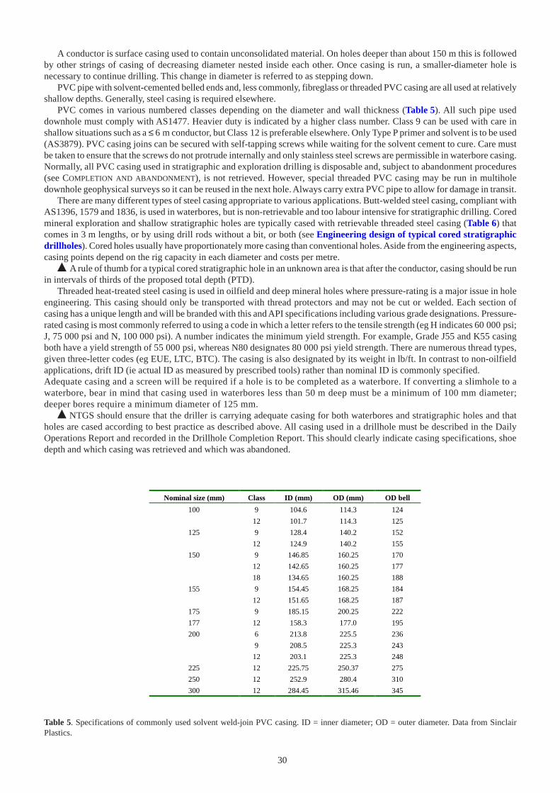
30
A conductor is surface casing used to contain unconsolidated material. On holes deeper than about 150 m this is followedby other strings of casing of decreasing diameter nested inside each other. Once casing is run, a smaller-diameter hole isnecessary to continue drilling. This change in diameter is referred to as stepping down.
PVC pipe with solvent-cemented belled ends and, less commonly, fibreglass or threaded PVC casing are all used at relativelyshallow depths. Generally, steel casing is required elsewhere.
PVC comes in various numbered classes depending on the diameter and wall thickness (Table 5). All such pipe useddownhole must comply with AS1477. Heavier duty is indicated by a higher class number. Class 9 can be used with care inshallow situations such as a ≤ 6 m conductor, but Class 12 is preferable elsewhere. Only Type P primer and solvent is to be used(AS3879). PVC casing joins can be secured with self-tapping screws while waiting for the solvent cement to cure. Care mustbe taken to ensure that the screws do not protrude internally and only stainless steel screws are permissible in waterbore casing.Normally, all PVC casing used in stratigraphic and exploration drilling is disposable and, subject to abandonment procedures(see COMPLETION AND ABANDONMENT), is not retrieved. However, special threaded PVC casing may be run in multiholedownhole geophysical surveys so it can be reused in the next hole. Always carry extra PVC pipe to allow for damage in transit.
There are many different types of steel casing appropriate to various applications. Butt-welded steel casing, compliant withAS1396, 1579 and 1836, is used in waterbores, but is non-retrievable and too labour intensive for stratigraphic drilling. Coredmineral exploration and shallow stratigraphic holes are typically cased with retrievable threaded steel casing (Table 6) thatcomes in 3 m lengths, or by using drill rods without a bit, or both (see Engineering design of typical cored stratigraphicdrillholes). Cored holes usually have proportionately more casing than conventional holes. Aside from the engineering aspects,casing points depend on the rig capacity in each diameter and costs per metre.
% A rule of thumb for a typical cored stratigraphic hole in an unknown area is that after the conductor, casing should be runin intervals of thirds of the proposed total depth (PTD).
Threaded heat-treated steel casing is used in oilfield and deep mineral holes where pressure-rating is a major issue in holeengineering. This casing should only be transported with thread protectors and may not be cut or welded. Each section ofcasing has a unique length and will be branded with this and API specifications including various grade designations. Pressure-rated casing is most commonly referred to using a code in which a letter refers to the tensile strength (eg H indicates 60 000 psi;J, 75 000 psi and N, 100 000 psi). A number indicates the minimum yield strength. For example, Grade J55 and K55 casingboth have a yield strength of 55 000 psi, whereas N80 designates 80 000 psi yield strength. There are numerous thread types,given three-letter codes (eg EUE, LTC, BTC). The casing is also designated by its weight in lb/ft. In contrast to non-oilfieldapplications, drift ID (ie actual ID as measured by prescribed tools) rather than nominal ID is commonly specified.Adequate casing and a screen will be required if a hole is to be completed as a waterbore. If converting a slimhole to awaterbore, bear in mind that casing used in waterbores less than 50 m deep must be a minimum of 100 mm diameter;deeper bores require a minimum diameter of 125 mm.
% NTGS should ensure that the driller is carrying adequate casing for both waterbores and stratigraphic holes and thatholes are cased according to best practice as described above. All casing used in a drillhole must be described in the DailyOperations Report and recorded in the Drillhole Completion Report. This should clearly indicate casing specifications, shoedepth and which casing was retrieved and which was abandoned.
Nominal size (mm) Class ID (mm) OD (mm) OD bell
100 9 104.6 114.3 124
12 101.7 114.3 125
125 9 128.4 140.2 152
12 124.9 140.2 155
150 9 146.85 160.25 170
12 142.65 160.25 177
18 134.65 160.25 188
155 9 154.45 168.25 184
12 151.65 168.25 187
175 9 185.15 200.25 222
177 12 158.3 177.0 195
200 6 213.8 225.5 236
9 208.5 225.3 243
12 203.1 225.3 248
225 12 225.75 250.37 275
250 12 252.9 280.4 310
300 12 284.45 315.46 345
Table 5. Specifications of commonly used solvent weld-join PVC casing. ID = inner diameter; OD = outer diameter. Data from SinclairPlastics.
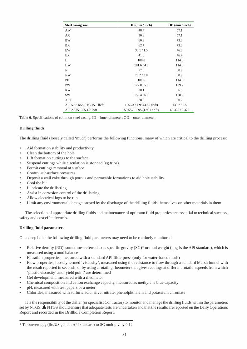
31
Table 6. Specifications of common steel casing. ID = inner diameter; OD = outer diameter.
Drilling fluids
The drilling fluid (loosely called ‘mud’) performs the following functions, many of which are critical to the drilling process:
• Aid formation stability and productivity• Clean the bottom of the hole• Lift formation cuttings to the surface• Suspend cuttings while circulation is stopped (eg trips)• Permit cuttings removal at surface• Control subsurface pressures• Deposit a wall cake through porous and permeable formations to aid hole stability• Cool the bit• Lubricate the drillstring• Assist in corrosion control of the drillstring• Allow electrical logs to be run• Limit any environmental damage caused by the discharge of the drilling fluids themselves or other materials in them
The selection of appropriate drilling fluids and maintenance of optimum fluid properties are essential to technical success,safety and cost effectiveness.
Drilling fluid parameters
On a deep hole, the following drilling fluid parameters may need to be routinely monitored:
• Relative density (RD), sometimes referred to as specific gravity (SG)* or mud weight (ppg is the API standard), which ismeasured using a mud balance
• Filtration properties, measured with a standard API filter press (only for water-based muds)• Flow properties, loosely termed ‘viscosity’, measured using the resistance to flow through a standard Marsh funnel with
the result reported in seconds, or by using a rotating rheometer that gives readings at different rotation speeds from which‘plastic viscosity’ and ‘yield point’ are determined
• Gel development, measured with a rheometer• Chemical composition and cation exchange capacity, measured as methylene blue capacity• pH, measured with test papers or a meter• Chlorides, measured with sulfuric acid, silver nitrate, phenolphthalein and potassium chromate
It is the responsibility of the driller (or specialist Contractor) to monitor and manage the drilling fluids within the parametersset by NTGS. % NTGS should ensure that adequate tests are undertaken and that the results are reported on the Daily OperationsReport and recorded in the Drillhole Completion Report.
Steel casing size ID (mm / inch) OD (mm / inch)
AW 48.4 57.1
AX 50.8 57.1
BW 60.3 73.0
BX 62.7 73.0
EW 38.1 / 1.5 46.0
EX 41.3 46.4
H 100.0 114.3
HW 101.6 / 4.0 114.3
N 77.8 88.9
NW 76.2 / 3.0 88.9
PF 101.6 114.3
PW 127.0 / 5.0 139.7
RW 30.1 36.5
SW 152.4 / 6.0 168.2
XRT 28.8 30.2
API 5.5” K55 LTC 15.5 lb/ft 125.73 / 4.95 (4.85 drift) 139.7 / 5.5
API 2.375” J55 4.7 lb/ft 50.55 / 1.995 (1.901 drift) 60.325 / 2.375
* To convert ppg (lbs/US gallon; API standard) to SG multiply by 0.12
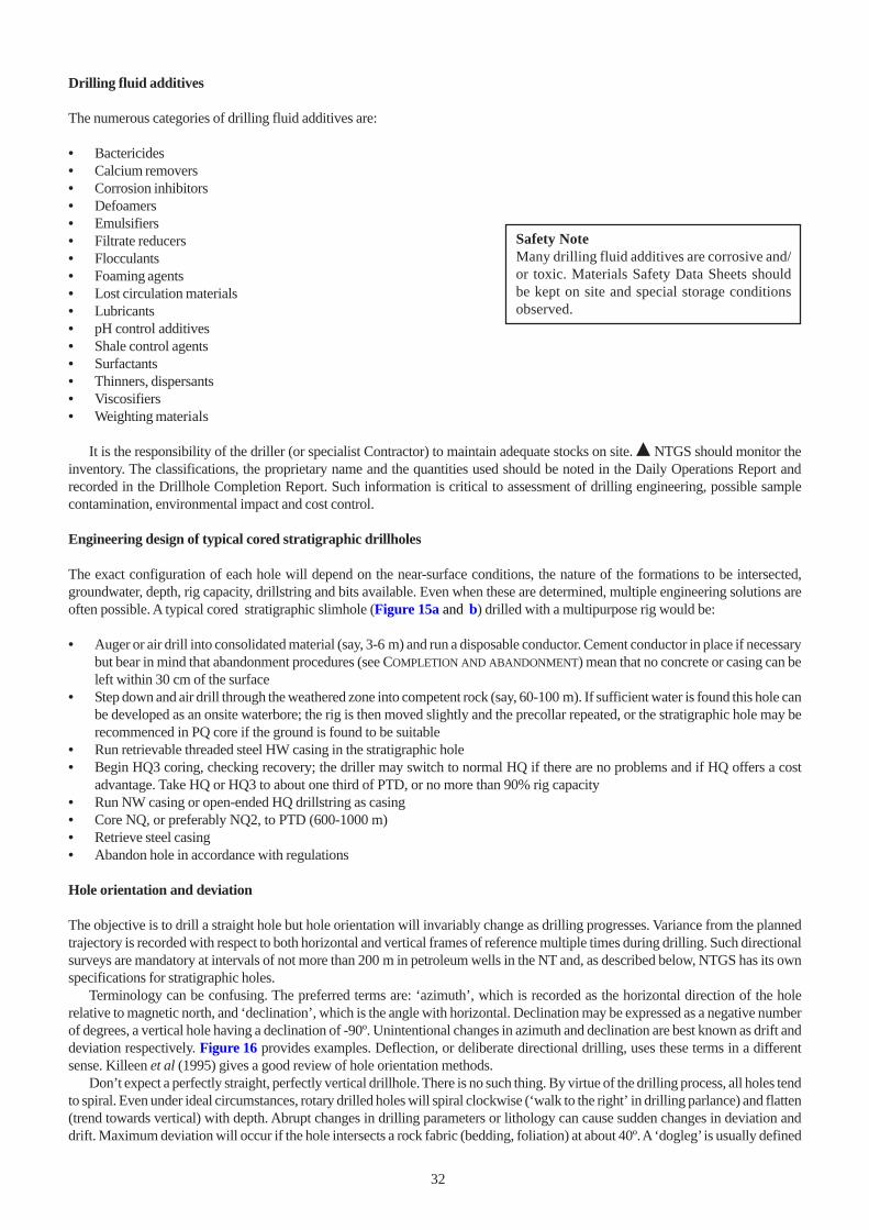
32
Drilling fluid additives
The numerous categories of drilling fluid additives are:
• Bactericides• Calcium removers• Corrosion inhibitors• Defoamers• Emulsifiers• Filtrate reducers• Flocculants• Foaming agents• Lost circulation materials• Lubricants• pH control additives• Shale control agents• Surfactants• Thinners, dispersants• Viscosifiers• Weighting materials
It is the responsibility of the driller (or specialist Contractor) to maintain adequate stocks on site. % NTGS should monitor theinventory. The classifications, the proprietary name and the quantities used should be noted in the Daily Operations Report andrecorded in the Drillhole Completion Report. Such information is critical to assessment of drilling engineering, possible samplecontamination, environmental impact and cost control.
Engineering design of typical cored stratigraphic drillholes
The exact configuration of each hole will depend on the near-surface conditions, the nature of the formations to be intersected,groundwater, depth, rig capacity, drillstring and bits available. Even when these are determined, multiple engineering solutions areoften possible. A typical cored stratigraphic slimhole (Figure 15a and b) drilled with a multipurpose rig would be:
• Auger or air drill into consolidated material (say, 3-6 m) and run a disposable conductor. Cement conductor in place if necessarybut bear in mind that abandonment procedures (see COMPLETION AND ABANDONMENT) mean that no concrete or casing can beleft within 30 cm of the surface
• Step down and air drill through the weathered zone into competent rock (say, 60-100 m). If sufficient water is found this hole canbe developed as an onsite waterbore; the rig is then moved slightly and the precollar repeated, or the stratigraphic hole may berecommenced in PQ core if the ground is found to be suitable
• Run retrievable threaded steel HW casing in the stratigraphic hole• Begin HQ3 coring, checking recovery; the driller may switch to normal HQ if there are no problems and if HQ offers a cost
advantage. Take HQ or HQ3 to about one third of PTD, or no more than 90% rig capacity• Run NW casing or open-ended HQ drillstring as casing• Core NQ, or preferably NQ2, to PTD (600-1000 m)• Retrieve steel casing• Abandon hole in accordance with regulations
Hole orientation and deviation
The objective is to drill a straight hole but hole orientation will invariably change as drilling progresses. Variance from the plannedtrajectory is recorded with respect to both horizontal and vertical frames of reference multiple times during drilling. Such directionalsurveys are mandatory at intervals of not more than 200 m in petroleum wells in the NT and, as described below, NTGS has its ownspecifications for stratigraphic holes.
Terminology can be confusing. The preferred terms are: ‘azimuth’, which is recorded as the horizontal direction of the holerelative to magnetic north, and ‘declination’, which is the angle with horizontal. Declination may be expressed as a negative numberof degrees, a vertical hole having a declination of -90º. Unintentional changes in azimuth and declination are best known as drift anddeviation respectively. Figure 16 provides examples. Deflection, or deliberate directional drilling, uses these terms in a differentsense. Killeen et al (1995) gives a good review of hole orientation methods.
Don’t expect a perfectly straight, perfectly vertical drillhole. There is no such thing. By virtue of the drilling process, all holes tendto spiral. Even under ideal circumstances, rotary drilled holes will spiral clockwise (‘walk to the right’ in drilling parlance) and flatten(trend towards vertical) with depth. Abrupt changes in drilling parameters or lithology can cause sudden changes in deviation anddrift. Maximum deviation will occur if the hole intersects a rock fabric (bedding, foliation) at about 40º. A ‘dogleg’ is usually defined
Safety NoteMany drilling fluid additives are corrosive and/or toxic. Materials Safety Data Sheets shouldbe kept on site and special storage conditionsobserved.
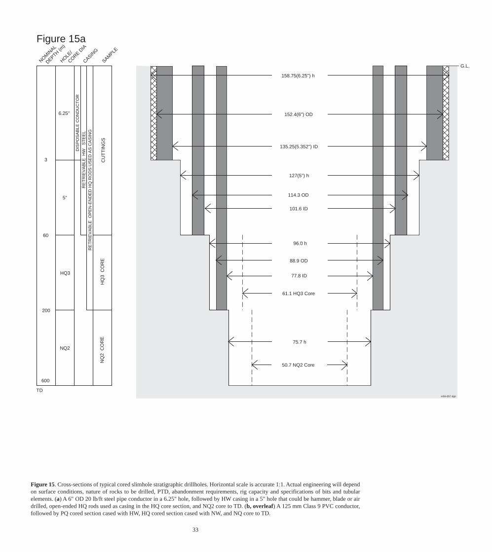
Figure 15. Cross-sections of typical cored slimhole stratigraphic drillholes. Horizontal scale is accurate 1:1. Actual engineering will dependon surface conditions, nature of rocks to be drilled, PTD, abandonment requirements, rig capacity and specifications of bits and tubularelements. (a) A 6" OD 20 lb/ft steel pipe conductor in a 6.25" hole, followed by HW casing in a 5" hole that could be hammer, blade or airdrilled, open-ended HQ rods used as casing in the HQ core section, and NQ2 core to TD. (b, overleaf) A 125 mm Class 9 PVC conductor,followed by PQ cored section cased with HW, HQ cored section cased with NW, and NQ core to TD.
m04-057.dgn
Figure 15a
3
200
600
TD
5"
6.25"
CU
TT
ING
S
RE
TR
IEV
AB
LE H
W
ST
EE
L
G.L.
158.75(6.25") h
114.3 OD
96.0 h
88.9 OD
75.7 h
NOMIN
AL
HOLE/
CASING
SAMPLE
CORE DIA
NQ
2 C
OR
EH
Q3
CO
RE
RE
TR
IEV
AB
LE O
PE
N-E
ND
ED
HQ
RO
DS
US
ED
AS
CA
SIN
G
DIS
PO
SA
BLE
CO
ND
UC
TO
R
60
50.7 NQ2 Core
61.1 HQ3 Core
77.8 ID
135.25(5.352") ID
127(5") h
101.6 ID
152.4(6") OD
HQ3
NQ2
DEPTH (m)
33
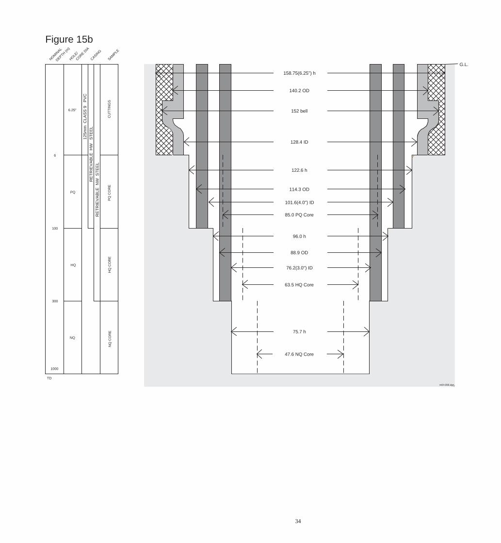
m04-058.dgn
Figure 15b
6
100
300
1000
TD
PQ
6.25"N
Q C
OR
EH
Q C
OR
EP
Q C
OR
EC
UT
TIN
GS
RE
TR
IEV
AB
LE H
W
ST
EE
L
G.L.
140.2 OD
158.75(6.25") h
152 bell
128.4 ID
122.6 h
114.3 OD
101.6(4.0") ID
85.0 PQ Core
96.0 h
88.9 OD
76.2(3.0") ID
63.5 HQ Core
75.7 h
47.6 NQ Core
NOMIN
AL
HOLE/
CASING
SAMPLE
CORE DIA
RE
TR
IEV
AB
LE N
W S
TE
EL
125m
m C
LAS
S 9
P
VC
DEPTH (m)
HQ
NQ
34
35
as any deviation >3º/30 m. Rotary holes will steepen with less weight on the bit and flatten with high weight on the bit. A dull bit willdeviate more from vertical than a new bit. The high rotation speeds and less pendular weight involved in coring mean that deviationis more of a tendency than with conventional drilling and that deviation becomes a more serious problem with decreasing holediameter. Deviation in excess of 10º is quite common in NQ cored holes in excess of 800 m and Hartley (1994) cites examples of upto 10º deviation over 30 m for BQ in schist. Significant deviation means that the drillhole may:
• Miss the target (especially important in mineral exploration)• No longer intersect bedding at 90º (not true stratigraphic thickness)• Contain sections of tight hole and doglegs that increase drag and wear on the drillstring and lead to further drilling problems
% All stratigraphic holes must be surveyed for deviation and preferably for drift. The NTGS contract stipulates thatreadings should be taken no more than 30 m apart. The actual depths will have to correspond to the end of core runs, anddepending on the lengths of collars, rods, subs and core barrel, this may not be exactly at absolute depths of 30 m, 60 m and soon. A good rule of thumb is that the difference in declination between adjacent readings should not exceed 2º. Any more than3º in 30 m is considered a dogleg. Insist that any spurious reading is repeated, if not before drilling is resumed, then no laterthan the end of the next run. If deviation becomes a problem, surveys should be more closely spaced while remedial action isunderway. Penalties will apply if deviation from the proposed program is excessive. Typical penalties are shown below:
Since this is part of monitoring the driller’s obligations under the contract, NTGS personnel must be familiar withhow deviation surveys are done and should check all measurements. These must be documented in the Daily OperationsReport.
Hole orientation can be recorded by numerous devices. These range from crude downhole acid-etch tubes (note thatNTGS forbids hydrofluoric acid (HF) on site), through combined compass and gravity tools and gyroscopic devices tocontinuous computer telemetry. The recommended types of equipment are described below.
Electronic memory tools
Several tools have been developed to record hole azimuth and declination electronically. This information can be viewedon a hand-held field computer and downloaded to a PC. The Flexit Multismart tool, for percussion holes, uses two non-magnetic stainless steel drill rods located behind the hammer and an electronic-memory survey tool in an inner tube.Data are recorded in 3 m increments as the rods are retrieved. Each reading takes less than 10 seconds. The Rangersurvey system is similar. The Tensor tool uses three magnetometers and two accelerometers to record hole declination,azimuth and magnetic tool-face readings. It can be run in both rotary and diamond core holes and operated either insingle-shot or continuous mode. Electronic multishot surveys are the preferred technique to survey percussion precollarssince correct precollar alignment is critical for the diamond tail. Such tools are usually only operated by a specialistContractor and would not normally be required on fully cored NTGS holes.
Eastman camera
The single-shot Eastman camera is the most widely used in coring. This is a downhole wireline photoclinometer thatincorporates a timer, camera, compass and inclinometer. Rubber fingers are used to centre the instrument and it is seateddownhole in a special non-magnetic collar. The type employed in near-vertical holes uses a battery-powered light toexpose a small disc of photographic film resembling a compass face, which is developed back at the surface as a permanentrecord of azimuth and declination. Although a special magnification device is available, few drillers have one and thecharts should be read with either a hand lens or a binocular microscope. Declination can be read to the nearest degree andestimated to 0.1º. Azimuth is read to the nearest 5º and can be estimated to the nearest degree. Be wary when reading theazimuth as most cameras photograph the card from underneath and so a reading east of north is read in a counterclockwisedirection (Figure 17). Some discs have 0-90° for each quadrant; others have a 0-360° compass scale. Note that the
Depth interval Deviation from planned vertical trajectory Penalty
0-300 m greater than or equal to 5° 5% of metreage rate until the hole is within specification or
enters another category
300-600 m greater than or equal to 7° 10% of metreage rate until the hole is within specification or
enters another category
>600 m greater than or equal to 10° 20% of metreage rate until the hole is within specification or
enters another category
any 30 m interval greater than or equal to 3° from previous reading 20% of metreage rate for the next 120 m
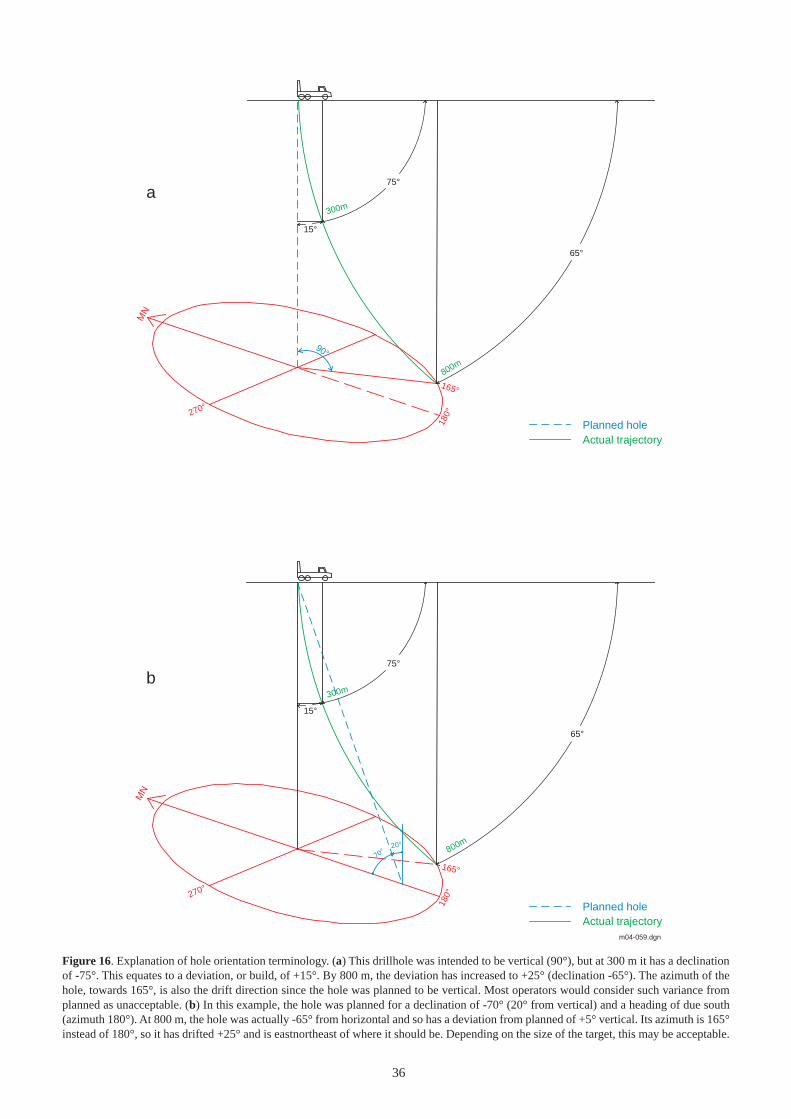
36
m04-059.dgn
65°
75°
270°
180°
165°
MN
300m
800m
15°
Planned holeActual trajectory
90°
65°
75°
270°
180°
165°
70°20°
300m
800m
15°
Planned holeActual trajectory
MN
a
b
Figure 16. Explanation of hole orientation terminology. (a) This drillhole was intended to be vertical (90°), but at 300 m it has a declinationof -75°. This equates to a deviation, or build, of +15°. By 800 m, the deviation has increased to +25° (declination -65°). The azimuth of thehole, towards 165°, is also the drift direction since the hole was planned to be vertical. Most operators would consider such variance fromplanned as unacceptable. (b) In this example, the hole was planned for a declination of -70° (20° from vertical) and a heading of due south(azimuth 180°). At 800 m, the hole was actually -65° from horizontal and so has a deviation from planned of +5° vertical. Its azimuth is 165°instead of 180°, so it has drifted +25° and is eastnortheast of where it should be. Depending on the size of the target, this may be acceptable.
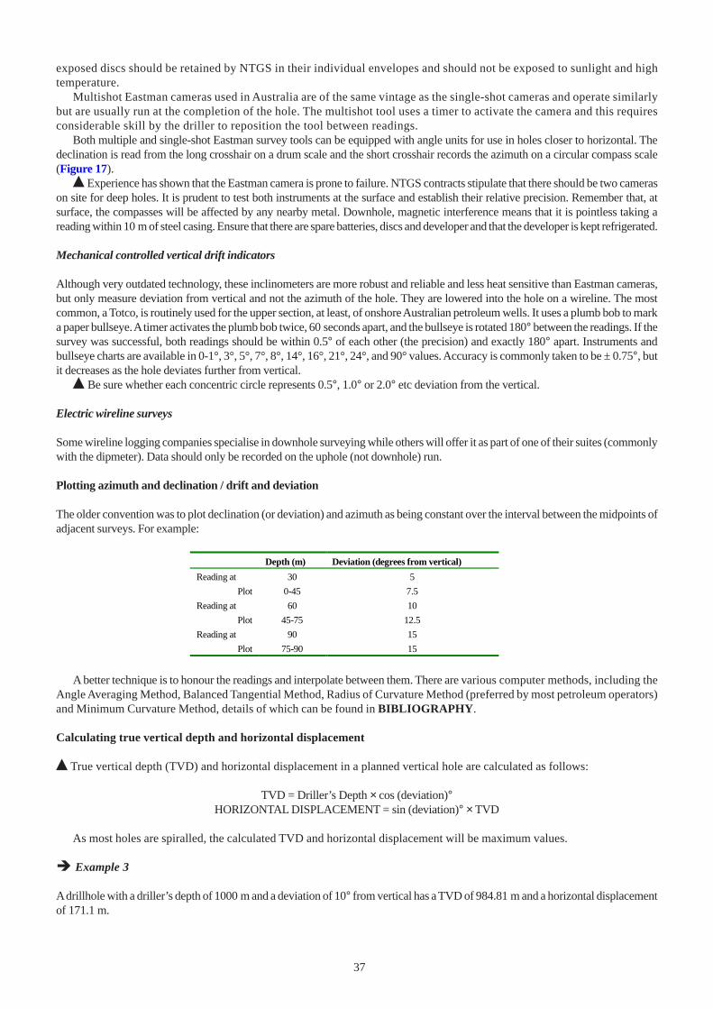
37
exposed discs should be retained by NTGS in their individual envelopes and should not be exposed to sunlight and hightemperature.
Multishot Eastman cameras used in Australia are of the same vintage as the single-shot cameras and operate similarlybut are usually run at the completion of the hole. The multishot tool uses a timer to activate the camera and this requiresconsiderable skill by the driller to reposition the tool between readings.
Both multiple and single-shot Eastman survey tools can be equipped with angle units for use in holes closer to horizontal. Thedeclination is read from the long crosshair on a drum scale and the short crosshair records the azimuth on a circular compass scale(Figure 17).
% Experience has shown that the Eastman camera is prone to failure. NTGS contracts stipulate that there should be two camerason site for deep holes. It is prudent to test both instruments at the surface and establish their relative precision. Remember that, atsurface, the compasses will be affected by any nearby metal. Downhole, magnetic interference means that it is pointless taking areading within 10 m of steel casing. Ensure that there are spare batteries, discs and developer and that the developer is kept refrigerated.
Mechanical controlled vertical drift indicators
Although very outdated technology, these inclinometers are more robust and reliable and less heat sensitive than Eastman cameras,but only measure deviation from vertical and not the azimuth of the hole. They are lowered into the hole on a wireline. The mostcommon, a Totco, is routinely used for the upper section, at least, of onshore Australian petroleum wells. It uses a plumb bob to marka paper bullseye. A timer activates the plumb bob twice, 60 seconds apart, and the bullseye is rotated 180° between the readings. If thesurvey was successful, both readings should be within 0.5° of each other (the precision) and exactly 180° apart. Instruments andbullseye charts are available in 0-1°, 3°, 5°, 7°, 8°, 14°, 16°, 21°, 24°, and 90° values. Accuracy is commonly taken to be ± 0.75°, butit decreases as the hole deviates further from vertical.
% Be sure whether each concentric circle represents 0.5°, 1.0° or 2.0° etc deviation from the vertical.
Electric wireline surveys
Some wireline logging companies specialise in downhole surveying while others will offer it as part of one of their suites (commonlywith the dipmeter). Data should only be recorded on the uphole (not downhole) run.
Plotting azimuth and declination / drift and deviation
The older convention was to plot declination (or deviation) and azimuth as being constant over the interval between the midpoints ofadjacent surveys. For example:
Depth (m) Deviation (degrees from vertical)
Reading at 30 5
Plot 0-45 7.5
Reading at 60 10
Plot 45-75 12.5
Reading at 90 15
Plot 75-90 15
A better technique is to honour the readings and interpolate between them. There are various computer methods, including the
Angle Averaging Method, Balanced Tangential Method, Radius of Curvature Method (preferred by most petroleum operators)and Minimum Curvature Method, details of which can be found in BIBLIOGRAPHY.
Calculating true vertical depth and horizontal displacement
% True vertical depth (TVD) and horizontal displacement in a planned vertical hole are calculated as follows:
TVD = Driller’s Depth × cos (deviation)°HORIZONTAL DISPLACEMENT = sin (deviation)° × TVD
As most holes are spiralled, the calculated TVD and horizontal displacement will be maximum values.
� Example 3
A drillhole with a driller’s depth of 1000 m and a deviation of 10° from vertical has a TVD of 984.81 m and a horizontal displacementof 171.1 m.
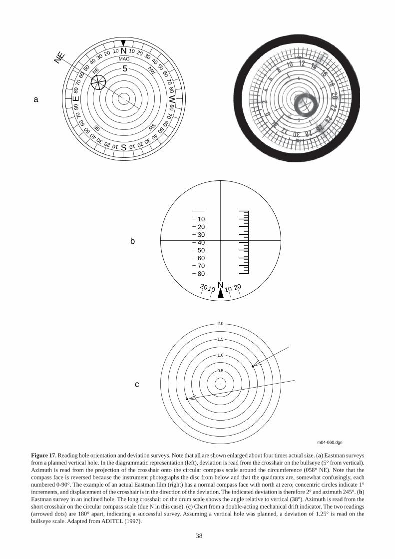
38
2.0
1.5
1.0
0.5
5
NE
N 10 20 30 40
5060
7080
8070
6050
4030201010203040
5060
7080
8070
6050
40 30 20 10
W
S
E
NW
NE
SWSE
MAG
1020304050607080
10 10 2020 N
m04-060.dgn
a
b
c
Figure 17. Reading hole orientation and deviation surveys. Note that all are shown enlarged about four times actual size. (a) Eastman surveysfrom a planned vertical hole. In the diagrammatic representation (left), deviation is read from the crosshair on the bullseye (5° from vertical).Azimuth is read from the projection of the crosshair onto the circular compass scale around the circumference (058° NE). Note that thecompass face is reversed because the instrument photographs the disc from below and that the quadrants are, somewhat confusingly, eachnumbered 0-90°. The example of an actual Eastman film (right) has a normal compass face with north at zero; concentric circles indicate 1°increments, and displacement of the crosshair is in the direction of the deviation. The indicated deviation is therefore 2° and azimuth 245°. (b)Eastman survey in an inclined hole. The long crosshair on the drum scale shows the angle relative to vertical (38°). Azimuth is read from theshort crosshair on the circular compass scale (due N in this case). (c) Chart from a double-acting mechanical drift indicator. The two readings(arrowed dots) are 180° apart, indicating a successful survey. Assuming a vertical hole was planned, a deviation of 1.25° is read on thebullseye scale. Adapted from ADITCL (1997).
39
Survey data presentation in NTGS reports
% The original survey discs are to be retained by NTGS. The NTGS Technical Note and Drillhole Completion Report will each havetabulated data and a graphical representation of hole trajectory.
DRILLING PROBLEMS
Drilling problems specific to coring are discussed in DRILLING PROBLEMS WHILE CORING; others are discussed below.
DRILLING PROBLEMS ASSOCIATED WITH THE FORMATION
% Under the terms of the contract, NTGS is liable for the extra costs these problems cause, so the Geologist has to be familiar withthem. Unless otherwise specified, remedial action is at the discretion of the driller and this is not a good time to harass the Contractor.
Taking a kick and a blowout
The first influx of overpressured liquid or gas into a drillhole is termed taking a kick. Any uncontrolled flow of hydrocarbons from thedrillhole is termed a blowout. Unexpectedly intersecting shallow gas has caused blowouts even on well engineered petroleum wells.It is disastrous in an inadequately cased hole with a rig that has no blowout preventer, spark arrestors and no kill mud on site. The riskof shallow gas can be evaluated from the overall petroleum prospectivity, the density of nearby waterbores and other drillholes thathave not intersected shallow gas.
Although shallow gas is a worst-case scenario, the same can be said for the potential of intersecting hydrocarbons (oil or gas)under pressure at any depth. A diamond core rig also runs the risk of inducing a blowout if the inner tube is retrieved at excessivespeed. The lowered pressure inside the drillstring will allow the influx of formation fluid. This is termed swabbing.
% No NTGS drillhole will be knowingly located on a potential structural or stratigraphic trap and particular attention must bepaid to any hole proposed to intersect known or suspected hydrocarbon reservoir. The final responsibility for site location withrespect to the risk of blowout rests with the Director NTGS.
Abnormal formation pressure
Intersecting rock that is under abnormally high formation (as opposed to hydrostatic) pressure can never be treated lightly. Worldwide,nearly one half of all onshore petroleum wells and more than one third of offshore wells have experienced trouble of one type oranother by drilling through overpressured formations. Although mostly confined to Mesozoic and younger sedimentary rocks, thenotion that overpressure doesn’t affect ‘old’ rocks is a fallacy. In addition, basins of any age that contain sulphate evaporites must betreated with extra caution.
Abnormal pressure can be generated in several ways:Compaction: pore water expands with increasing burial depth and increasing temperature, whereas the pore space is reduced by
increasing geostatic load. If pore water is prevented from escaping, the pore water will become overpressured. This is usually aproblem in thick, young shales. Compaction effects can be compounded by tectonic stress, salt or shale diapirism, etc.
Diagenesis: the following processes can all release free water, which if trapped in pore spaces, will give rise to abnormal pressure:smectite to illite clay diagenesis, recrystallisation of carbonates, gypsum to anhydrite transformation and diagenesis of volcanic ash(which also produces CO2 and CH4). In addition, diagenesis can produce impermeable barriers (eg stylolites) to further confineformation fluids.
Differential density: when a pore fluid present in any non-horizontal structure has a density significantly less than the normal porefluid density in the area, abnormal pressures can be encountered in the updip portion of the structure.
Fluid migration: the upward migration of fluids can result in a shallow formation becoming pressured (or ‘charged’). The path forsuch migration can be natural or man-made (eg casing leaks, bad cement jobs).
Thermal cracking of hydrocarbons: approximately 85 m3 of gas can be generated from the thermal cracking of one barrel of oil(Barker, 1990). The by-product organic compounds degrade further and become concentrated in the pore spaces, thus occludingpermeability and further contributing to the overpressure.
Tectonic effects: associated with faults.
Detecting overpressure
Detecting overpressure while drilling involves monitoring changes to lithology, drilling and circulation parameters as a transitionzone is intersected. The most obvious changes are:
• An increase in penetration rate, torque and drag through the transition zone into an overpressured shale• An increase in drilling fluid density and viscosity• Rotary drilling of an overpressured (‘sloughing’) shale will result in long crescent-shaped cuttings and a volume of cuttings
seemingly greater than the volume drilled
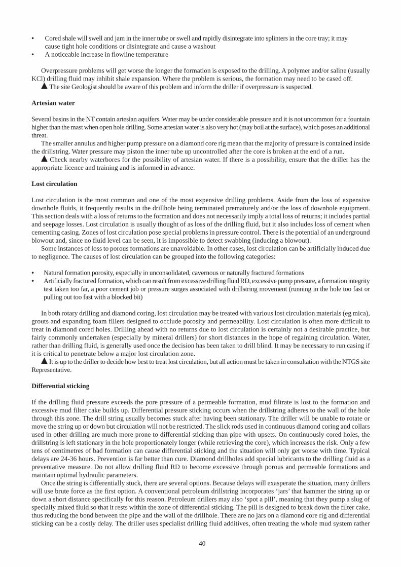
40
• Cored shale will swell and jam in the inner tube or swell and rapidly disintegrate into splinters in the core tray; it maycause tight hole conditions or disintegrate and cause a washout
• A noticeable increase in flowline temperature
Overpressure problems will get worse the longer the formation is exposed to the drilling. A polymer and/or saline (usuallyKCl) drilling fluid may inhibit shale expansion. Where the problem is serious, the formation may need to be cased off.
% The site Geologist should be aware of this problem and inform the driller if overpressure is suspected.
Artesian water
Several basins in the NT contain artesian aquifers. Water may be under considerable pressure and it is not uncommon for a fountainhigher than the mast when open hole drilling. Some artesian water is also very hot (may boil at the surface), which poses an additionalthreat.
The smaller annulus and higher pump pressure on a diamond core rig mean that the majority of pressure is contained insidethe drillstring. Water pressure may piston the inner tube up uncontrolled after the core is broken at the end of a run.
% Check nearby waterbores for the possibility of artesian water. If there is a possibility, ensure that the driller has theappropriate licence and training and is informed in advance.
Lost circulation
Lost circulation is the most common and one of the most expensive drilling problems. Aside from the loss of expensivedownhole fluids, it frequently results in the drillhole being terminated prematurely and/or the loss of downhole equipment.This section deals with a loss of returns to the formation and does not necessarily imply a total loss of returns; it includes partialand seepage losses. Lost circulation is usually thought of as loss of the drilling fluid, but it also includes loss of cement whencementing casing. Zones of lost circulation pose special problems in pressure control. There is the potential of an undergroundblowout and, since no fluid level can be seen, it is impossible to detect swabbing (inducing a blowout).
Some instances of loss to porous formations are unavoidable. In other cases, lost circulation can be artificially induced dueto negligence. The causes of lost circulation can be grouped into the following categories:
• Natural formation porosity, especially in unconsolidated, cavernous or naturally fractured formations• Artificially fractured formation, which can result from excessive drilling fluid RD, excessive pump pressure, a formation integrity
test taken too far, a poor cement job or pressure surges associated with drillstring movement (running in the hole too fast orpulling out too fast with a blocked bit)
In both rotary drilling and diamond coring, lost circulation may be treated with various lost circulation materials (eg mica),grouts and expanding foam fillers designed to occlude porosity and permeability. Lost circulation is often more difficult totreat in diamond cored holes. Drilling ahead with no returns due to lost circulation is certainly not a desirable practice, butfairly commonly undertaken (especially by mineral drillers) for short distances in the hope of regaining circulation. Water,rather than drilling fluid, is generally used once the decision has been taken to drill blind. It may be necessary to run casing ifit is critical to penetrate below a major lost circulation zone.
% It is up to the driller to decide how best to treat lost circulation, but all action must be taken in consultation with the NTGS siteRepresentative.
Differential sticking
If the drilling fluid pressure exceeds the pore pressure of a permeable formation, mud filtrate is lost to the formation andexcessive mud filter cake builds up. Differential pressure sticking occurs when the drillstring adheres to the wall of the holethrough this zone. The drill string usually becomes stuck after having been stationary. The driller will be unable to rotate ormove the string up or down but circulation will not be restricted. The slick rods used in continuous diamond coring and collarsused in other drilling are much more prone to differential sticking than pipe with upsets. On continuously cored holes, thedrillstring is left stationary in the hole proportionately longer (while retrieving the core), which increases the risk. Only a fewtens of centimetres of bad formation can cause differential sticking and the situation will only get worse with time. Typicaldelays are 24-36 hours. Prevention is far better than cure. Diamond drillholes add special lubricants to the drilling fluid as apreventative measure. Do not allow drilling fluid RD to become excessive through porous and permeable formations andmaintain optimal hydraulic parameters.
Once the string is differentially stuck, there are several options. Because delays will exasperate the situation, many drillerswill use brute force as the first option. A conventional petroleum drillstring incorporates ‘jars’ that hammer the string up ordown a short distance specifically for this reason. Petroleum drillers may also ‘spot a pill’, meaning that they pump a slug ofspecially mixed fluid so that it rests within the zone of differential sticking. The pill is designed to break down the filter cake,thus reducing the bond between the pipe and the wall of the drillhole. There are no jars on a diamond core rig and differentialsticking can be a costly delay. The driller uses specialist drilling fluid additives, often treating the whole mud system rather
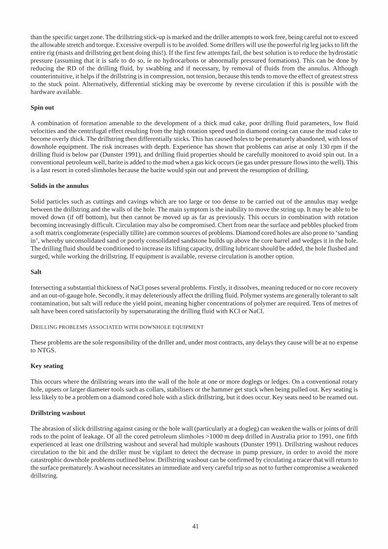
41
than the specific target zone. The drillstring stick-up is marked and the driller attempts to work free, being careful not to exceedthe allowable stretch and torque. Excessive overpull is to be avoided. Some drillers will use the powerful rig leg jacks to lift theentire rig (masts and drillstring get bent doing this!). If the first few attempts fail, the best solution is to reduce the hydrostaticpressure (assuming that it is safe to do so, ie no hydrocarbons or abnormally pressured formations). This can be done byreducing the RD of the drilling fluid, by swabbing and if necessary, by removal of fluids from the annulus. Althoughcounterintuitive, it helps if the drillstring is in compression, not tension, because this tends to move the effect of greatest stressto the stuck point. Alternatively, differential sticking may be overcome by reverse circulation if this is possible with thehardware available.
Spin out
A combination of formation amenable to the development of a thick mud cake, poor drilling fluid parameters, low fluidvelocities and the centrifugal effect resulting from the high rotation speed used in diamond coring can cause the mud cake tobecome overly thick. The drillstring then differentially sticks. This has caused holes to be prematurely abandoned, with loss ofdownhole equipment. The risk increases with depth. Experience has shown that problems can arise at only 130 rpm if thedrilling fluid is below par (Dunster 1991), and drilling fluid properties should be carefully monitored to avoid spin out. In aconventional petroleum well, barite is added to the mud when a gas kick occurs (ie gas under pressure flows into the well). Thisis a last resort in cored slimholes because the barite would spin out and prevent the resumption of drilling.
Solids in the annulus
Solid particles such as cuttings and cavings which are too large or too dense to be carried out of the annulus may wedgebetween the drillstring and the walls of the hole. The main symptom is the inability to move the string up. It may be able to bemoved down (if off bottom), but then cannot be moved up as far as previously. This occurs in combination with rotationbecoming increasingly difficult. Circulation may also be compromised. Chert from near the surface and pebbles plucked froma soft matrix conglomerate (especially tillite) are common sources of problems. Diamond cored holes are also prone to ‘sandingin’, whereby unconsolidated sand or poorly consolidated sandstone builds up above the core barrel and wedges it in the hole.The drilling fluid should be conditioned to increase its lifting capacity, drilling lubricant should be added, the hole flushed andsurged, while working the drillstring. If equipment is available, reverse circulation is another option.
Salt
Intersecting a substantial thickness of NaCl poses several problems. Firstly, it dissolves, meaning reduced or no core recoveryand an out-of-gauge hole. Secondly, it may deleteriously affect the drilling fluid. Polymer systems are generally tolerant to saltcontamination, but salt will reduce the yield point, meaning higher concentrations of polymer are required. Tens of metres ofsalt have been cored satisfactorily by supersaturating the drilling fluid with KCl or NaCl.
DRILLING PROBLEMS ASSOCIATED WITH DOWNHOLE EQUIPMENT
These problems are the sole responsibility of the driller and, under most contracts, any delays they cause will be at no expenseto NTGS.
Key seating
This occurs where the drillstring wears into the wall of the hole at one or more doglegs or ledges. On a conventional rotaryhole, upsets or larger diameter tools such as collars, stabilisers or the hammer get stuck when being pulled out. Key seating isless likely to be a problem on a diamond cored hole with a slick drillstring, but it does occur. Key seats need to be reamed out.
Drillstring washout
The abrasion of slick drillstring against casing or the hole wall (particularly at a dogleg) can weaken the walls or joints of drillrods to the point of leakage. Of all the cored petroleum slimholes >1000 m deep drilled in Australia prior to 1991, one fifthexperienced at least one drillstring washout and several had multiple washouts (Dunster 1991). Drillstring washout reducescirculation to the bit and the driller must be vigilant to detect the decrease in pump pressure, in order to avoid the morecatastrophic downhole problems outlined below. Drillstring washout can be confirmed by circulating a tracer that will return tothe surface prematurely. A washout necessitates an immediate and very careful trip so as not to further compromise a weakeneddrillstring.
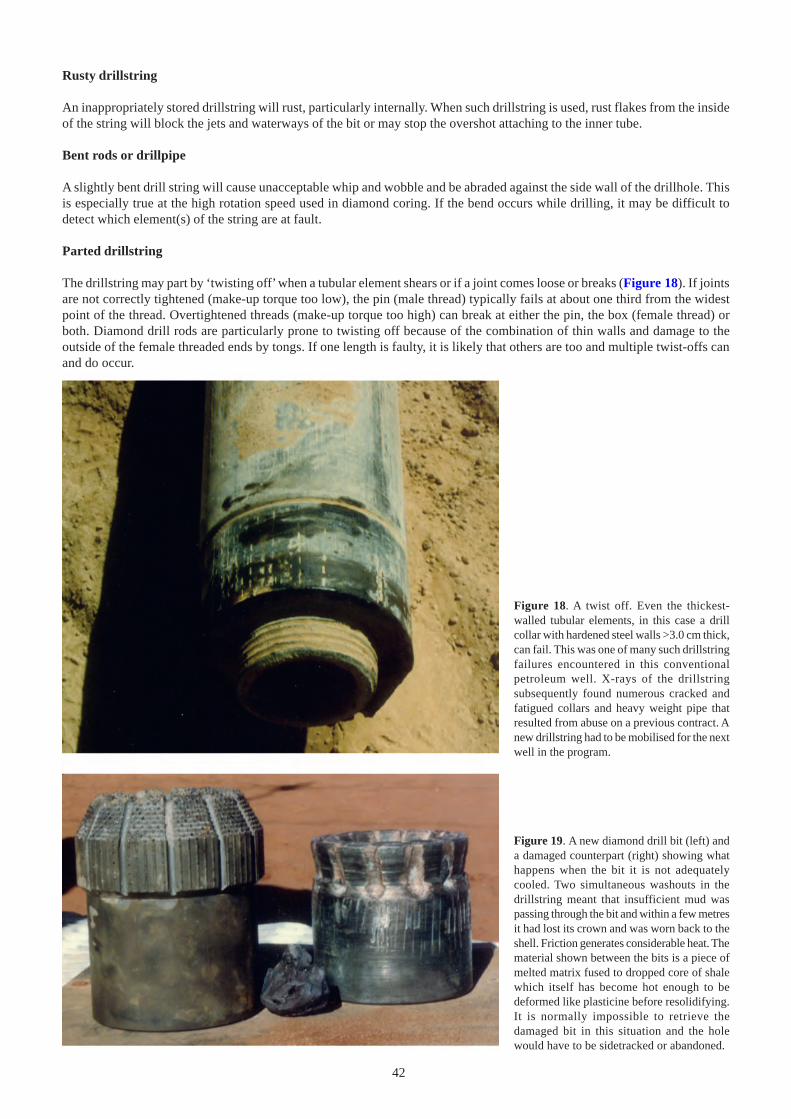
42
Rusty drillstring
An inappropriately stored drillstring will rust, particularly internally. When such drillstring is used, rust flakes from the insideof the string will block the jets and waterways of the bit or may stop the overshot attaching to the inner tube.
Bent rods or drillpipe
A slightly bent drill string will cause unacceptable whip and wobble and be abraded against the side wall of the drillhole. Thisis especially true at the high rotation speed used in diamond coring. If the bend occurs while drilling, it may be difficult todetect which element(s) of the string are at fault.
Parted drillstring
The drillstring may part by ‘twisting off’ when a tubular element shears or if a joint comes loose or breaks (Figure 18). If jointsare not correctly tightened (make-up torque too low), the pin (male thread) typically fails at about one third from the widestpoint of the thread. Overtightened threads (make-up torque too high) can break at either the pin, the box (female thread) orboth. Diamond drill rods are particularly prone to twisting off because of the combination of thin walls and damage to theoutside of the female threaded ends by tongs. If one length is faulty, it is likely that others are too and multiple twist-offs canand do occur.
Figure 18. A twist off. Even the thickest-walled tubular elements, in this case a drillcollar with hardened steel walls >3.0 cm thick,can fail. This was one of many such drillstringfailures encountered in this conventionalpetroleum well. X-rays of the drillstringsubsequently found numerous cracked andfatigued collars and heavy weight pipe thatresulted from abuse on a previous contract. Anew drillstring had to be mobilised for the nextwell in the program.
Figure 19. A new diamond drill bit (left) anda damaged counterpart (right) showing whathappens when the bit it is not adequatelycooled. Two simultaneous washouts in thedrillstring meant that insufficient mud waspassing through the bit and within a few metresit had lost its crown and was worn back to theshell. Friction generates considerable heat. Thematerial shown between the bits is a piece ofmelted matrix fused to dropped core of shalewhich itself has become hot enough to bedeformed like plasticine before resolidifying.It is normally impossible to retrieve thedamaged bit in this situation and the holewould have to be sidetracked or abandoned.
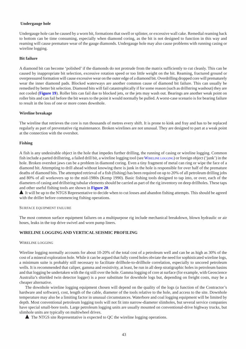
43
Undergauge hole
Undergauge hole can be caused by a worn bit, formations that swell or splinter, or excessive wall cake. Remedial reaming backto bottom can be time consuming, especially when diamond coring, as the bit is not designed to function in this way andreaming will cause premature wear of the gauge diamonds. Undergauge hole may also cause problems with running casing orwireline logging.
Bit failure
A diamond bit can become ‘polished’ if the diamonds do not protrude from the matrix sufficiently to cut cleanly. This can becaused by inappropriate bit selection, excessive rotation speed or too little weight on the bit. Reaming, fractured ground oroverpressured formation will cause excessive wear on the outer edge of a diamond bit. Overdrilling dropped core will prematurelywear the inner diamond pads. Blocked waterways are another common cause of diamond bit failure. This can usually beremedied by better bit selection. Diamond bits will fail catastrophically if for some reason (such as drillstring washout) they arenot cooled (Figure 19). Roller bits can fail due to blocked jets, or the jets may wash out. Bearings are another weak point onroller bits and can fail before the bit wears to the point it would normally be pulled. A worst-case scenario is for bearing failureto result in the loss of one or more cones downhole.
Wireline breakage
The wireline that retrieves the core is run thousands of metres every shift. It is prone to kink and fray and has to be replacedregularly as part of preventative rig maintenance. Broken wirelines are not unusual. They are designed to part at a weak pointat the connection with the overshot.
Fishing
A fish is any undesirable object in the hole that impedes further drilling, the running of casing or wireline logging. Commonfish include a parted drillstring, a failed drill bit, a wireline logging tool (see WIRELINE LOGGING) or foreign object (‘junk’) in thehole. Broken overshot jaws can be a problem in diamond coring. Even a tiny fragment of metal can ring or wipe the face of adiamond bit. Attempting to drill ahead without knowing there is junk in the hole is responsible for over half of the prematuredeaths of diamond bits. The attempted retrieval of a fish (fishing) has been required on up to 20% of all petroleum drilling jobsand 80% of all workovers up to the mid-1980s (Kemp 1990). Basic fishing tools designed to tap into, or over, each of thediameters of casing and drillstring tubular elements should be carried as part of the rig inventory on deep drillholes. These tapsand other useful fishing tools are shown in Figure 20.% It will be up to the NTGS Representative to decide when to cut losses and abandon fishing attempts. This should be agreedwith the driller before commencing fishing operations.
SURFACE EQUIPMENT FAILURE
The most common surface equipment failures on a multipurpose rig include mechanical breakdown, blown hydraulic or airhoses, leaks in the top drive swivel and worn pump liners.
WIRELINE LOGGING AND VERTICAL SEISMIC PROFILING
WIRELINE LOGGING
Wireline logging normally accounts for about 10-20% of the total cost of a petroleum well and can be as high as 30% of thecost of a mineral exploration hole. While it can be argued that fully cored holes obviate the need for sophisticated wireline logs,a minimum suite is probably still necessary to facilitate drillhole-to-drillhole correlation, especially to uncored petroleumwells. It is recommended that caliper, gamma and resistivity, at least, be run in all deep stratigraphic holes in petroleum basinsand that logging be undertaken with the rig still over the hole. Gamma logging of core at surface (for example, with GeoscienceAustralia’s shielded twin detector logger) is a poor substitute for downhole logs but, depending on freight costs, may be acheaper alternative.
The downhole wireline logging equipment chosen will depend on the quality of the logs (a function of the Contractor’shardware and software), cost, length of the cable, diameter of the tools relative to the hole, and access to the site. Downholetemperature may also be a limiting factor in unusual circumstances. Waterbore and coal logging equipment will be limited bydepth. Most conventional petroleum logging tools will not fit into narrow-diameter slimholes, but several service companieshave special small-bore tools. Large petroleum logging units are usually mounted on conventional-drive highway trucks, butslimhole units are typically on multiwheel drives.
% The NTGS site Representative is expected to QC the wireline logging operations.
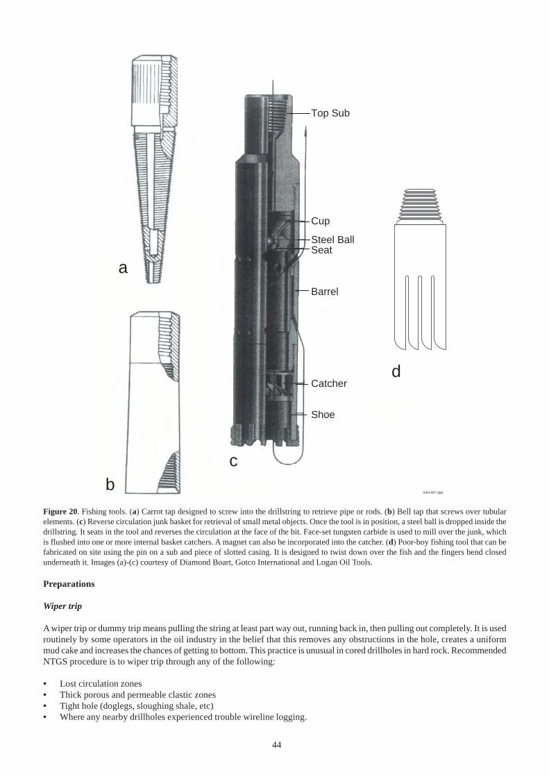
44
Preparations
Wiper trip
A wiper trip or dummy trip means pulling the string at least part way out, running back in, then pulling out completely. It is usedroutinely by some operators in the oil industry in the belief that this removes any obstructions in the hole, creates a uniformmud cake and increases the chances of getting to bottom. This practice is unusual in cored drillholes in hard rock. RecommendedNTGS procedure is to wiper trip through any of the following:
• Lost circulation zones• Thick porous and permeable clastic zones• Tight hole (doglegs, sloughing shale, etc)• Where any nearby drillholes experienced trouble wireline logging.
Shoe
Catcher
Barrel
SeatSteel Ball
Cup
Top Sub
m04-067.dgn
a
bc
d
Figure 20. Fishing tools. (a) Carrot tap designed to screw into the drillstring to retrieve pipe or rods. (b) Bell tap that screws over tubularelements. (c) Reverse circulation junk basket for retrieval of small metal objects. Once the tool is in position, a steel ball is dropped inside thedrillstring. It seats in the tool and reverses the circulation at the face of the bit. Face-set tungsten carbide is used to mill over the junk, whichis flushed into one or more internal basket catchers. A magnet can also be incorporated into the catcher. (d) Poor-boy fishing tool that can befabricated on site using the pin on a sub and piece of slotted casing. It is designed to twist down over the fish and the fingers bend closedunderneath it. Images (a)-(c) courtesy of Diamond Boart, Gotco International and Logan Oil Tools.
45
Conditioning and sampling the drilling fluid prior to wireline logging
Correct sampling and analysis of the drilling fluid in the hole during logging is critical to the evaluation of resistivity andself-potential (SP) logs. The drilling fluid is sometimes ‘sweetened up’ (particularly in terms of viscosity) prior to logging.This practice should be resisted for the following reasons:
• If the drilling fluid could be improved, it should have been done during active circulation while drilling• Changes to the physical properties of the drilling fluid are invariably accompanied by chemical changes• Downhole conditions will still be equilibrating when logging commences and will vary during logging• The drilling fluid that has penetrated the formation may not be physically displaced by any newly conditioned
drilling fluid, but cation exchange will be operating
The recommended drilling fluid preparation prior to logging is simply to circulate bottoms up, preferably twice. Thetime circulation stopped and the final flowline temperature should appear on log headers. The last mud sample circulatedoff bottom should be sampled for filtrate and mud cake evaluation. Mud resistivity measurements should be made twice,once immediately after collection and again about midway through the entire logging process. Ensure that the correctmud data, including the temperature, appear on the log header. A quick check for unweighted mud is:
Rmf should be 0.75-0.88 times RmRmc should be 1.11-1.50 times Rmf
where the various resistivities are: Rm - mud, Rmf -filtrate and Rmc – mud cake.
Recording datum and depth
The header should show the datum being used and both driller’s and wireline total depths. These depths are rarely thesame. The wireline depth is usually less, often because cavings prevent the tool getting to bottom. There are otherreasons for discrepancy. Even assuming that the measuring wheel is accurately calibrated and there is no slippage, twistingcan shorten the cable by a few percent. In the opposite sense, cable has an elastic stretch of up to 0.8 m per 1000 m. Thewireline depth should be calibrated against casing shoe depth. In the case of oilfield API casing, the casing depth will beknown to within millimetres and should be more precise than the wireline.
SAFETY
% If logging is to be undertaken with the rig still over the hole, ensure that the work area is free of obstructions. Thedrillers will assist the logging Contractor to rig up. All other personnel not directly involved must be kept away from thearea around the drill floor and from any logging tools laid out on the surface. The hole shall be covered at all times unlessthere is a tool in the hole and a slotted cover should be used while logs are being run. All sheaves should be properlyguarded and loads must be moved across the cable when logging operations are underway. Other general safety proceduresoutlined in SAFETY AND EMERGENCY PROCEDURES shall be followed.
Logging suite
Most operators will be able to provide preliminary hard copy and final digital data on site. Typical vertical scales generatedon site are 1:200 and 1:500. It is handy to have a hardcopy at the same vertical scale as the site lithological log. Thedigital version should include LIS and/or LAS ≥1.0 format.
Tools with a radioactive source are never to be the first logs run. Logs which do not read through casing need only berun 5-10 m into it. Repeat intervals vary from tool to tool but 5-10 m should be considered a minimum.
There are dozens of ever-changing, impressive-sounding proprietary names for the various wireline logging tools.The basic generic types are described below.
Mechanical caliper
PrincipleMeasures the vertical change in diameter and sometimes shape of hole with mechanical arms; holds other instrumentsagainst the hole wall
UsesQC of depth on other wireline logs, detection of tight hole or washouts in hole wall that might compromise quality of other log data,calculation of hole volume for cementing
DisplayUse metric even if the bit is in inches; the bit diameter may be shown as a dotted line for comparison with hole gauge
46
CalibrationCalibrated against rings of known diameter or casing ID
LimitationsLow repeatability, particularly of single arm tool, because of elliptical hole; badly out of gauge holes will exceed caliperreach
ChecksCheck casing reads correctly
Natural gamma ray
PrincipleScintillometric measurement of natural radioactivity, usually as total counts; spectral tools will record separate K, Thand U
UsesDefinition of bed boundaries, lithological identification, correlation, establishment of ‘shale’ base line, detection ofradioactive ore deposits and feldspathic sandstones, matching of separate logging runs
DisplayAPI units, 0-100 API or 0-200 API units, linear, increasing to left
CalibrationTest pit
LimitationsTool must be centred; absolute reading will depend on detector type, logging speed and time constant; thick mud cakemay influence readings; largely unaffected by caving and will read through casing, but is attenuated; barite, KCl and/ormica (added to combat lost circulation) in drilling fluid will affect readings, subject to temporal variation (drift); verticalresolution of a basic tool is about 0.5 m so thin beds tend to ‘smear’ and inflection points appear displaced
ChecksBe sure that logging speed is recorded and that the time constant used was appropriate for that speed; repeatability variesby lithology and due to random drift; some detectors are temperature sensitive; zero readings are impossible (lowest inevaporites)
Spontaneous potential (SP)
PrincipleMeasures difference between the electrochemical potential of a downhole movable electrode and another fixed at thesurface to detect relative difference in salinities of connate water (Rw) and mud filtrate (Rmf). Uses the same geometryas the resistivity tool and is commonly run in combination
UsesDetect permeable beds, bed boundaries; determine Rw and Rmf, definition of shale base line; gives qualitative indicationof ‘shaliness’
DisplayMillivolts (mV), 10 mV per division, linear scale, negative to left
LimitationsLimited by salinity of fluids, if water salinity and mud filtrate are close, as normally is the case in a freshwater aquifer;the SP curve will be too flat and of limited use; some filtrate invasion must be present; useless in cased hole; needscorrection for bed thickness, resistivity and hole diameter; sensitive to electrical interference
ChecksMust have good earth connection for surface electrode; check for unacceptable baseline drift and cycling due to magnetismand bimetallism, telluric affects and cable noise
47
Resistivity and conductivity
PrincipleAside from some ore minerals, there are relatively few highly conductive materials in the subsurface, so the conductivityof sedimentary formations is often a function of the salinity of the formation fluid. Various types of tools have beendesigned to measure the comparative resistivities (the inverse of conductivity) at different depths of wall invasion. Electricalconductivity is usually measured with an induction probe
UsesResistivity is a good direct indicator of hydrocarbons, to obtain numerical measures of Rw and Rt for use in the Archie equation todetermine Sw (water saturation), determine oil/water contacts; short-spaced tools good for drillhole-to-drillhole correlation. Conductivitymeasurements are important for calibrating airborne EM data
DisplayResistivity 0.2-200 or 0.2-2000 ohm, four-decade logarithmic, shallowest reading shown as a solid line, intermediate as dashed anddeep as dotted
CalibrationPrecision resistors
LimitationsDependant on instrument pad/mud cake contact; has to be corrected for temperature, hole and adjacent bed effects; useless in air-filled hole, in non-conductive fluids (use IP instead) or cased hole; long- and short-spaced resistivity have different vertical resolutionand respond differently to borehole effects; tool is physically long and needs significant sump
ChecksAll resistivity readings should be at or near zero in casing; run repeat section over zones of interests
Induced polarisation (IP)
PrincipleA transmitter loop charges the formation with a high alternating current. Any conductive particles will become the mosthighly charged with eddy currents. The magnitude of the currents, proportional to the media conductivity, is monitoredusing a detector loop. Modern tools have four or more transmitter/receiver pairs. May be run with resistivity tool
UsesPrimarily used in minerals exploration for disseminated sulfides such as volcanic-hosted massive sulfides and porphyrycopper deposits; also used in coal exploration. Some application to uranium exploration in detecting zones of alterationand redox fronts. Downhole IP may help calibrate surface IP surveys, although it can be difficult to detect if a drillholetargeted on an IP anomaly has actually intersected it
DisplayVarious, normally inverted and displayed on a logarithmic scale
LimitationsWill not work in casing; will work in air and non-conductive fluids; temperature dependant
ChecksCompare with other electrical tools, particularly resistivity
Magnetic susceptibility
PrincipleMeasures the ratio of the intensity of natural magnetisation to the intensity of an applied magnetic field; operates in asimilar way to an IP tool; maghemite, ilmenite and pyrrhotite will all register high responses
UsesMineral exploration, detecting palaeochannels, crude lithology determination
DisplaySince it is a ratio, it is strictly dimensionless

48
LimitationsMeasurements in highly conductive material need to be corrected for conductivity affects
ChecksCompare with electrical tools
Sonic
PrincipleMeasures the speed of pulsed compressional sound waves in subsurface formations (acoustic travel time); both first arrival andfull waveform tools are available. The tool usually comes in two parts, with a lower transmitter separated from one or moreupper receivers
UsesLithology determination, especially in carbonate and evaporite rocks; porosity evaluation; generation of synthetic seismograms;abnormal pressure indicator
DisplayDelta t microseconds/metre, range 500-100 µsec/m, usually linear, Φs 45 to -15 percent porosity
CalibrationCalibrated against a quartz crystal clock, function checked at surface, but a bent tool could pass all checks and produceerroneous logs
LimitationsTools are usually compensated for changes in hole size and tool tilt; assumes uniform intergranular porosity; cannot recognisesecondary porosity; may not show gas in consolidated rock; useless in casing; not a pad-type tool so will work in out of gaugeholes but may cycle-skip
ChecksLook for cycle skipping or spurious spikes and slow the tool if more than two spikes per 50 m; sonic in liquid-filled casingshould read 187.0 µsec/m (= 57 µsec/ft); values <131 µsec/m or >623 µsec/m are unusual; sonic should register closely withgamma
Density
PrincipleMeasurement of radioactivity loss between an emitting source (usually 2 curie 137Cs) and return of gamma rays to one or moredetectors. Loss of energy is by collision with electrons, the electron density being proportional to the bulk density. Compensatedtools use short- and long-spaced detectors to correct for mud cake. Both source and detectors are heavily shielded to minimiseborehole effects
UsesPorosity evaluation; determination of absolute bulk density, shale content; gas detection
Display1.90-2.90 g/cm3 or 1.95-2.95 g/cm3, linear; may be displayed relative to the selected matrix (limestone or sandstone)
CalibrationShop calibrated in blocks of known density; onsite tool verification using two small gamma sources
LimitationsResidual hydrocarbons, especially gas, will give erroneously high porosity; susceptible to shaliness; grain density must beknown quite accurately to calculate porosity, eg a variation of ±0.05 g/cm3 can produce an error of 2.6% porosity; is a pad tooland so dependant on hole gauge; relatively slow logging speed so be wary in unstable holes - not a tool to get stuck in the hole!
ChecksConfirm logging speed; repeat section in good hole should be within 0.05 g/cm3; check for drift; check density of knownuniform lithology (eg halite 2.032 g/cm3, granite 2.5-2.8 g/cm3)
49
Neutron
PrincipleA neutron source (commonly 20 curie AmBe) bombards the formation with neutrons which are captured by atoms in both theformation fluid and matrix. Because of the similarity in mass, most neutrons are captured by hydrogen atoms in water orhydrocarbons which in turn reflect formation porosity. The compensated neutron tool uses two thermal detectors as sensors
UsesDelineation of porous zones, determination of formation fluid type, direct indication of gas, evaluation of shale content; incombination with density to identify lithology
DisplayEither limestone, sandstone or less commonly dolostone porosity units; usually displayed with density
CalibrationShop calibration in water-filled tank; on site using two small radioactive sources
LimitationsElements such as Cl, B and Li interfere; cannot distinguish between water and medium density oil; is influenced by changes inhole diameter; will work through steel casing but PVC (which contains H) will cause a problem; temperature dependant; shalecontent needs to be verified using another log; not a tool to get stuck in the hole!
ChecksCross-check with density and gamma
Dipmeter
PrincipleShows bedding by comparing the depth shift in four or more microrestistivity sensors
UsesDip determination, fracture identification; can replace other microresistivity tools
DisplayNeeds onsite processing to generate tadpole diagrams
CalibrationAs per resisitivity
LimitationsOne or more arms not contacting the wall (floating arm problem)
ChecksAs per resistivity
Downhole temperature
PrincipleRecord sufficient downhole temperature data for correction of wireline logs and drilling fluid resistivity and allow estimationof geothermal gradient
UsesMany of the wireline logs, notably resistivity, vary as a function of temperature. Correct values of Rm, Rw, Rmf, Rmc and K allrequire the temperature of the zone under investigation. Flowline temperature should have been recorded prior to cessation ofcirculation. Digital temperature logs, where available, are usually run on the way down as one of the first logs and again as oneof the last runs. Normal procedure is to record the bottom hole temperature using a maximum reading thermometer on eachrun. Simple as this may sound, experience has shown that up to a quarter of such readings are unreliable. Failure to reset thethermometer after leaving the tool sitting in the sun doesn’t help. Downhole temperature should be recorded at every opportunityand the time since circulation stopped is also important to calculate a time-dependant correction
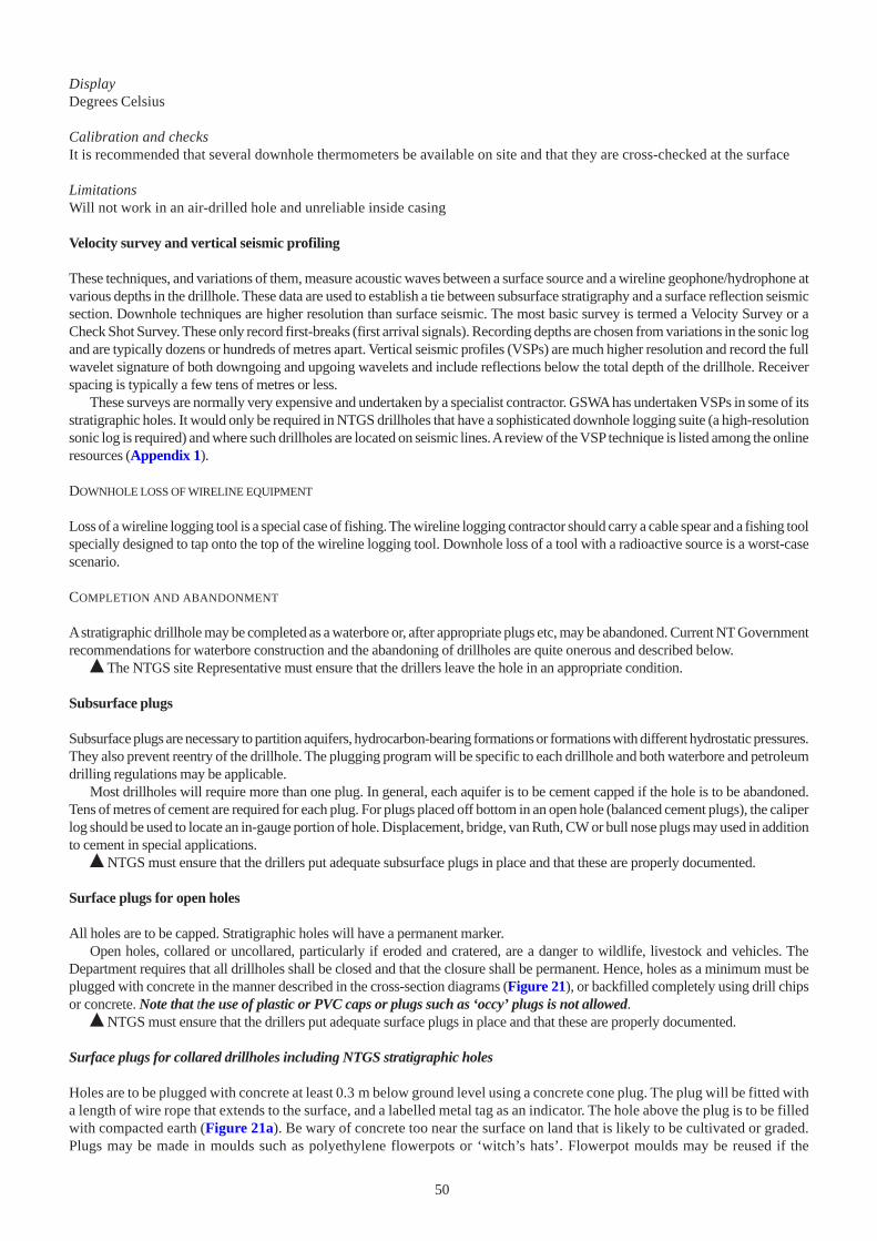
50
DisplayDegrees Celsius
Calibration and checksIt is recommended that several downhole thermometers be available on site and that they are cross-checked at the surface
LimitationsWill not work in an air-drilled hole and unreliable inside casing
Velocity survey and vertical seismic profiling
These techniques, and variations of them, measure acoustic waves between a surface source and a wireline geophone/hydrophone atvarious depths in the drillhole. These data are used to establish a tie between subsurface stratigraphy and a surface reflection seismicsection. Downhole techniques are higher resolution than surface seismic. The most basic survey is termed a Velocity Survey or aCheck Shot Survey. These only record first-breaks (first arrival signals). Recording depths are chosen from variations in the sonic logand are typically dozens or hundreds of metres apart. Vertical seismic profiles (VSPs) are much higher resolution and record the fullwavelet signature of both downgoing and upgoing wavelets and include reflections below the total depth of the drillhole. Receiverspacing is typically a few tens of metres or less.
These surveys are normally very expensive and undertaken by a specialist contractor. GSWA has undertaken VSPs in some of itsstratigraphic holes. It would only be required in NTGS drillholes that have a sophisticated downhole logging suite (a high-resolutionsonic log is required) and where such drillholes are located on seismic lines. A review of the VSP technique is listed among the onlineresources (Appendix 1).
DOWNHOLE LOSS OF WIRELINE EQUIPMENT
Loss of a wireline logging tool is a special case of fishing. The wireline logging contractor should carry a cable spear and a fishing toolspecially designed to tap onto the top of the wireline logging tool. Downhole loss of a tool with a radioactive source is a worst-casescenario.
COMPLETION AND ABANDONMENT
A stratigraphic drillhole may be completed as a waterbore or, after appropriate plugs etc, may be abandoned. Current NT Governmentrecommendations for waterbore construction and the abandoning of drillholes are quite onerous and described below.
% The NTGS site Representative must ensure that the drillers leave the hole in an appropriate condition.
Subsurface plugs
Subsurface plugs are necessary to partition aquifers, hydrocarbon-bearing formations or formations with different hydrostatic pressures.They also prevent reentry of the drillhole. The plugging program will be specific to each drillhole and both waterbore and petroleumdrilling regulations may be applicable.
Most drillholes will require more than one plug. In general, each aquifer is to be cement capped if the hole is to be abandoned.Tens of metres of cement are required for each plug. For plugs placed off bottom in an open hole (balanced cement plugs), the caliperlog should be used to locate an in-gauge portion of hole. Displacement, bridge, van Ruth, CW or bull nose plugs may used in additionto cement in special applications.
% NTGS must ensure that the drillers put adequate subsurface plugs in place and that these are properly documented.
Surface plugs for open holes
All holes are to be capped. Stratigraphic holes will have a permanent marker.Open holes, collared or uncollared, particularly if eroded and cratered, are a danger to wildlife, livestock and vehicles. The
Department requires that all drillholes shall be closed and that the closure shall be permanent. Hence, holes as a minimum must beplugged with concrete in the manner described in the cross-section diagrams (Figure 21), or backfilled completely using drill chipsor concrete. Note that the use of plastic or PVC caps or plugs such as ‘occy’ plugs is not allowed.
% NTGS must ensure that the drillers put adequate surface plugs in place and that these are properly documented.
Surface plugs for collared drillholes including NTGS stratigraphic holes
Holes are to be plugged with concrete at least 0.3 m below ground level using a concrete cone plug. The plug will be fitted witha length of wire rope that extends to the surface, and a labelled metal tag as an indicator. The hole above the plug is to be filledwith compacted earth (Figure 21a). Be wary of concrete too near the surface on land that is likely to be cultivated or graded.Plugs may be made in moulds such as polyethylene flowerpots or ‘witch’s hats’. Flowerpot moulds may be reused if the
51
drainage holes are blocked with masking tape and the inside wiped with diesel or the mould may be left on the plug. PVCcollars may be readily cut below ground level using a powered brushcutter modified with a diamond masonry blade. If necessary,the cut section of collar may be removed from the hole using chain tongs or an oil filter remover.
Plugs for uncollared RAB holes
Holes are to be plugged at least 1.0 m below ground level with a concrete cone plug. The plug is to be at least 50 mm largerthan the diameter of the original drillhole but, depending on the nature of the ground, must be of sufficient size as to remainfirmly in position. To enable the placement of the plug the hole may be reamed out with hand tools or counterbored by thedrillrig with a larger drill bit. The hole above the plug is to be backfilled with compacted earth and mounded over at the surface.(Figure 21b). The intention is that water shall not enter the hole and cause it to erode and reopen, and particular care isrequired to ensure the long-term effectiveness of the plug.
Waterbore completion
Waterbore completion must follow NT Government recommendations. The top of the production casing must be a minimum500 mm above ground level. Should any other casing be installed it must be a minimum 300 mm above ground level. Thewaterbore will be completed with a locked cap. A reinforced concrete slab surrounds the base of the casing(s). The concreteslab must have a minimum thickness of 100 mm and a minimum diameter of 1 m. The bottom of the cement must be a minimumof 25 mm below the natural ground surface and the top level 75 mm above the natural ground surface. The concrete must be asuitable mix of cement, gravel and sand. The surface of the slab must slope away from the casing(s). A bore marker post 2.3 mlong and ≥50 mm diameter must be placed approximately 6 m from the completed or abandoned bore. This post will beinserted to a depth of 450 mm and cemented. The bore marker shall have the Registered Number welded clearly on the post andthe post shall be painted white.
% NTGS must ensure that the drillers complete waterbores in accordance with the appropriate legislation as described above.
SITE RESTORATION
% NTGS is responsible for site restoration. The site should be restored to its original contours except that the area around thecollar must not be a depression. If runoff could erode the site, it should be ripped along the contours and spoon drains constructed.It is not normally necessary to replant the site, except on agricultural land. The NTGS site Representative must obtain beforeand after photographs of the drill location for inclusion in the Drillhole Completion Report.
ACKNOWLEDGEMENTS AND DISCLAIMERS
This manual is intended for informal internal use within NTGS and comes with a standard disclaimer found at the start ofthis document. Figures and photographs reproduced here are with the permission of the relevant agencies. This does notmean that NTGS or the NT Government endorses these products or suppliers. This manual was proofread by MasoodAhmad and Tim Munson. The layout owes much to comments by James Groombridge. Figures were prepared by RichardJong and Marianne Fuller.
Figure 21. Hole abandonment details. (a) PVC-collared drillhole with concrete plug. (b) Uncollared drillhole with subsurface concrete plug.
rea
med
-ou
t _ <
1.0
m
0.3
m m
inim
um
compacted fill
concrete plug
a b
52
BIBLIOGRAPHY
Australian Drilling Industry Training Committee Limited (ADITCL), 1997. Drilling: the manual of methods, applications,and management. Fourth edition. CRC Press, Florida.A comprehensive drillers’ textbook relevant to Australian equipment; covers all types of drilling.
Barker C, 1990. Calculated volume and pressure changes during the thermal cracking of oil to gas in reservoirs. AmericanAssociation of Petroleum Geologists, Bulletin 74, 1254-1261.
Blackbourn GA, 1990. Cores and core logging for geologists. Whittles Publishing Services, Caithness.A basic manual on core logging and handling, mainly directed at the oil industry.
Chugh CP, 1971. Diamond drilling. Oxford & IBH Publishing Company, New Delhi.Very dated overview of diamond core drilling written by the Geological Survey of India.
Dunster JN, 1991. Wellsite Manual. Comalco Aluminum Limited. Internal Report.Comprehensive wellsite manual for onshore conventional petroleum drilling, used by several international joint ventures.
Fraser K, 1991. Managing drilling operations. Elsevier Applied Science, London, New York.A succinct text from the United Kingdom that provides a good overview of petroleum drilling operations.
Hartley JS, 1994. Drilling - tools and programme management. AA Balkema Publishers, Rotterdam.A very useful Australian overview of drilling with good treatment of continuous diamond coring, aimed at wellsite geologists.
Heinz WF, 1994. Diamond drilling handbook. Third edition. Sigma Press, Halfway House (Ganteng province, South Africa).A comprehensive, well illustrated and well written textbook on coring; some engineering aspects are unique to SouthAfrica.
Jensen HI, 1915. Report on diamond drilling in the Northern Territory. Bulletin of the Northern Territory of Australia 12,March 1915.Historical interest.
Kemp G, 1990. Oilwell fishing operations: tools and techniques. Second edition. Gulf, Houston.The classic reference to fishing operations in the petroleum industry.
Killeen PG, Bernius GR and Mwenifumbo CJ, 1995. Surveying the path of boreholes: a review of orientation methods andexperiences. Proceedings of the 6th International MGLS Symposium on Borehole Geophysics for Minerals, Geotechnicaland Groundwater Applications. October 22-25, 1995, Santa Fe, New Mexico.Available at: http://www.mgls.org/95Sym/Papers/Killeen/ Includes a comparison of five different techniques in the samehole.
Marjoribanks RW, 1997. Geological methods in mineral exploration and mining. Chapman & Hall, London.A practical guide that includes core logging, orientation and sampling; evolved from the Australian Manual of geologicalpractise used in many university courses.
McPhater D and MacTeirnan B, 1983. Well-site geologist’s handbook. McKinlay-Smith International Limited, Penn WellBooks, Tulsa.A basic, very practical wellsite guide for petroleum drilling.
Moore PL, 1986. Drilling practices manual. Second edition. Penn Well Books, Petroleum Publishing Company, Tulsa.A standard text directed at conventional rotary petroleum drilling; numerous worked examples of calculations.
Seubert BW, 1995. PT, PetroPEP Nusantara, Jakarta. The wellsite guide. An introduction to geological wellsite operations.Version 5 September 2000. http://www.petropep.de/W_Guide.pdfA manual for petroleum mudlogging.
Swanson RG, 1981. Sample examination manual. American Association of Petroleum Geologists, Methods in ExplorationSeries, Tulsa.An ex-Shell manual that became the AAPG industry standard for the collection and presentation of data on a conventionalpetroleum wellsite.

53
Whittaker AH, 1987. Mud logging: Chapter 12 in Bradley HB (editor) Petroleum engineering handbook. Society of PetroleumEngineers, Richardson, Texas.Bradley (1987) is arguably the textbook on petroleum engineering, now in its third (1992) edition.
Wyman RA and Castano JR, 1974. Show descriptions from core, sidewall and ditch samples. SPWLA 15th Annual LoggingSymposium, June 2-5, 1974.Reviews common methods of testing for shows in cores, sidewall samples and ditch samples, together with a simplemethod of recording these observations in a consistent manner.
54
APPENDIX 1 – ONLINE RESOURCES
GLOSSARIES OF DRILLING TERMS
Generalhttp://www.doir.wa.gov.au/minerals/glossary.html
Glossaries of oilfield and drilling termshttp://www.glossary.oilfield.slb.com/http://www.akita-drilling.com/glossary_of_drilling_terms.htmhttp://www.ukooa.co.uk/ukooa/glossary.htmhttp://www.osha.gov/SLTC/etools/oilandgas/glossary_of_terms/glossary_of_terms_a.htmlhttp://www.mms.gov/glossary/index.htm
Ocean Drilling Program dictionaryhttp://www-odp.tamu.edu/publications/dictionary/dict-intro.html
Drilling for groundwaterhttp://www.agwt.org/info/R_Terms.asp
Glossary of casing and pipe termshttp://www.inter-mountain.com/glossary.htm
SAFETY MANUALS
Diamond drilling safety manualhttp://www.boartlongyear.com/catalogues/PDFS/diamond.pdf
Geotechnical drilling operations and inspectionhttp://www.doh.dot.state.nc.us/safety/wpsm/ch11b/37.html
Queensland exploration safety guidelineshttp://www.nrm.qld.gov.au/mines/exploration/pdf/explsafe.pdf
WIRELINE LOGGING
Wireline logging and log analysishttp://www.reeves-wireline.com/pdfmineralscatalog/LogAnalMinApps.PDF
Vertical seismic profilinghttp://www.mines.edu/students/p/pjbrown/vsp_paper.pdf (and links therein)

55
AAPG American Association of PetroleumGeologists
AFE authorisation for expenditureAPI American Petroleum InstituteBBL US barrel (approximately 159 L); BBL
is API standard, bbl is preferred bymost journals
BHA bottom hole assemblyBHT Broken Hill-typeBOP blowout preventerC&C condition and circulateC&F cartage and freightCIF cartage, insurance, freightCIRC circulateCSD casing shoe depthDC drill collarDCDMA Diamond Core Drill Manufacturers
AssociationDEMOB demobilisationDDR daily drilling reportDOR daily operations reportDP drillpipeDST drillstem testECD equivalent circulating densityEOH end of holeEMW equivalent mud weightF filtrateF formation factorFIS free in storeFIT formation integrity testFLT flowline temperatureFW freshwaterGL ground levelGNC gross nominal capacityID inside diameterIP induced polarisation (log)K absolute permeabilityKB (depth below) Kelly bushingLC lost circulationLCM lost circulation materialMIRU move in, rig upMOB mobilisationNB new bitNFG not functionalNR no returnsOD outside diameterOH open holeP&A plugged and abandonedPBTD plugged back total depthPDC polycrystalline diamond compactPDQ pretty damn quick
POOH pull out of holeppf pound per foot (use lb/ft)ppg pounds per gallon (ppg is API standard)PTD proposed total depthPV plastic viscosity (mud)QC quality controlRC reverse circulationRD relative densityRDMO rig down, move outREC recovered / recoveryRIH run in holeRm resistivity of mudRmc resistivity of mud cakeRmf resistivity of mud filtrateRo residual oil saturationROP rate of penetrationRPM revolutions per minuteRt resistivity of invaded zoneRTSTM rate too small too measureRw formation water resistivityRxo resistivity of flushed zoneSG specific gravitySw water saturationSW saltwaterSWC sidewall coreSWL standing water levelSX sacksTCI tungsten carbide insert (bit)TD total depthTDS total dissolved salts / solidsTOC total organic carbonTr traceTS thin sectionTSTM too small too measureTVD true vertical depthTWT two-way timeUDR universal drill rigUS unservicableUV ultravioletVSP vertical seismic profileWL water loss (mud)WOB weight on bitWOC wait on cementWOD wait on daylightWOO wait on ordersWOT wait on toolsWOW wait on weatherWTS water to surfaceX/O crossover (in drillstring)Y/P yield point (mud)
APPENDIX 2 – GLOSSARY OF COMMONLY USED ABBREVIATIONS

56
APPENDIX 3 – DAILY OPERATIONS REPORT
The following form is for use on deep cored stratigraphic holes. It can be modified to suit other types of drilling. % This or asimilar form must be completed and dispatched to the office every 24 hours for the time the rig is on site or in transit to anotherNTGS drillhole. If no fax is available, normal practice is to dictate the contents of the form over the phone.
Cum = cumulativeEst = estimatedPTD = proposed total depth
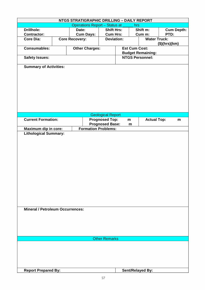
57
NTGS STRATIGRAPHIC DRILLING – DAILY REPORT Operations Report – Status at _____ hrs
Drillhole: Contractor:
Date: Cum Days:
Shift Hrs: Cum Hrs:
Shift m: Cum m:
Cum Depth: PTD:
Core Dia:
Core Recovery: Deviation: Water Truck: ($)(hrs)(km)
Consumables:
Other Charges: Est Cum Cost: Budget Remaining:
Safety Issues: NTGS Personnel:
Summary of Activities:
Geological Report Current Formation: Prognosed Top: m
Prognosed Base: m Actual Top: m
Maximum dip in core: Formation Problems: Lithological Summary:
Mineral / Petroleum Occurrences:
Other Remarks
Report Prepared By: Sent/Relayed By:

58
APPENDIX 4 – NTGS DRILLING LOG
This is a simple generic form. It can be modified to suit the needs of specific projects.
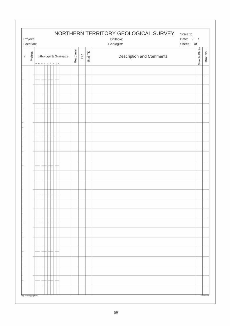
59
m04-055.dgn
NORTHERN TERRITORY GEOLOGICAL SURVEY
Geologist:
Project:
Location:
Scale 1:
i
Met
res
Dip
Bed
TK
Description and Comments
Sam
ple/
Pho
to
Box
No.
P G V C M F V Z C Rec
over
y
Drillhole:
Lithology & Grainsize
ntgs core logging form.
Date: / /
Sheet: of

60
APPENDIX 5 – HYDROCARBON SHOW LOG
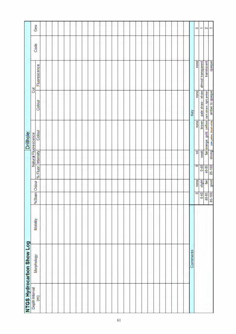
61

62
INDEX
abandonment, 50abnormal formation pressure, 39accident report, 9acid bounce test, 25acute bedding to core angle, 20additives, 32air coring, 11alcohol, control of, 7angled hole, 2, 5arrow up, 17artesian water, 40audit, 4Australian Standards, 1, 7Authorisation for Expenditure, 4azimuth, 17, 32, 35azimuth and declination, plotting, 37bedding to core angle, 20bent drill string, 42bit failure, 43bitumen, 28blade bit, 1blowout, 39blowout preventer, 2, 39BOP, 2broken wirelines, 43budget, 4caliper, 45camp, 6capacity of core trays, 14carbonaceous matter, 28casing, 29, 32cavings, 41CHD101, 11CHD134, 11CHD76, 11check shot survey, 50clothing, 7completion, 6, 50composite core sampling, 21conductivity, 47conductor, 30connection gas, 27contamination, 14, 23, 28, 29, 41continuous coring, 2, 10, 16conventional coring, 10core barrel, 10, 11core catching, 16core diameters, 10-11, 22core logging, 21core marking, 16core loss, 17core orientation, 16, 17core trays, 14, 16, 17, 21core tray lids, 14, 17, 21coring, 10, 32crush cut, 23, 28cut fluorescence, 27, 28Daily Operations Report, 5, 6, 7, 30, 31, 32, 35, 56DCDMA, 11
DCIS Accident Report, 9declination, 32, 35, 37density, 39, 48depth marks, 17derrick, 2describing core, 21deviation, 20, 32, 35, 37deviation survey, 35diamond bit, 11, 43diesel, 28, 51differential sticking, 40dipmeter, 49dogleg, 32, 41DOR, 5downhole hammer, 1downhole temperature, 49drift, 32, 37drill gas, 27drill pipe, 2drill rod, 2, 41, 42driller’s blocks, 14, 16, 17Drillhole Completion Report, 6, 21, 30, 31, 32, 39, 51drillhole naming convention, 6drilling fluid, 31, 45drilling problems, 14, 39drilling types, 1drillstring washout, 40, 41, 43dropped core, 14, 43drugs, prohibition of, 7duty of care, 9earthworks, 4Eastman camera, 35, 37edge matching core, 16, 17emergency procedures, 6engineering, 29environmental impact, 6evacuation, 8, 10evaporite, 5, 14, 39, 46, 48fault, 5, 39fire, 6, 7, 8, 9, 23first aid kit, 9, 10first aid officer, 10fish, 43fishing, 43, 50fluorescence, 22, 23, 26, 27, 28foam, 1, 32foam filler, 39formation pressure, 39fractured formation, 5, 14, 40fuel, 4, 7gamma ray, 46gas, 22gas hazard, 8geochemical samples, 1, 21, 23, 28geological description, 6groundwater, 8, 28guards, 8H
2S, 8
hard hats, 7Hazard Report, 9hazardous substances, 7, 9

63
hole size, 11hole termination, 6hoses, 8hot water extraction, 25HQ, 11, 14, 21, 32, 33HQ3, 11, 32HW, 11, 31, 32hydrocarbon fluorescence, 23, 26hydrocarbon indications, spurious, 27incident investigation, 9, 10incident report, 9, 10inclinometer, 35induced polarisation, 47inner tube, 8, 10, 11, 14, 16, 17, 28, 39Invitation to Tender, 4, 6IP, 47Kelly bushing, 2, 17key seat, 41kick, 39, 41labelling core trays, 17lids, core tray, 14, 17, 21lining core trays, 14logging core, 21loss of wireline logging tool, 43, 50lost circulation, 5, 28, 29, 32, 40, 44magnetic susceptibility, 47marking core, 16mast, 2, 5, 7, 9, 41maximum dip, 20medical condition, 7metadata, 6methane, 28mineral rig, 2, 8mist, 1motor vehicle accident, 9, 10mud, 5, 31, 45mud weight, 31multielement geochemistry, 21multipurpose rig, 2, 32, 43multishot camera, 35, 37NaCl, 41neutron, 49NQ, 11, 14, 21, 22, 32, 35NQ2, 11, 14, 32NTGS drillhole naming convention, 6NTGS Technical Note, 4, 5, 6, 21, 39NW, 11, 31, 32oil bleed, 23oil sample, 25, 29oil show description, 25open hole drilling, 1, 2, 50open hole samples, 28orientation lines, 16orientation mark, 18overdrilled core, 14overpressure, 39overpressured formation, 5, 14, 43overshot, 10, 42, 43pallets, 21PDC, 11penetration rate, 1, 11, 39
percussion-marked core, 18petroleum rig, 2, 8, 10phenolphthalein, 21, 31photographing core, 17, 20pipe dope, 28planning, 4, 5plugging holes, 50, 51polyweave, 29PQ, 11, 14, 21, 22, 32PQ3, 11precollar, 1, 32, 35pressure hoses, 8pressure relief valves, 8pulldown, 2pulling out, 2, 10, 40, 44PVC casing, 30PW, 31RAB, 1, 51radioactive source, 8, 45, 50radius of curvature method, 37RC, 1RD, 27, 31, 40, 41relative density, 27, 31, 40, 41reporting systems, 9resistivity, 47risks, 5roller bit, 1, 43running in, 2, 40rust, 29, 42safety, 5, 6, 7, 8, 9, 10, 14, 45safety boots, 7safety glasses, 7, 16, 23safety harness, 7safety induction, 7, 10safety meetings, 5, 7salt, 39, 41sample bags, 28, 29sample comtamination, 29sample depths, 17sample interval, 5sanding in, 41satellite phone, 10sealing oil-soaked core, 23SG, 31shallow gas, 39shift duration, 6show number, 27single-shot camera, 35site layout, 6site restoration, 4, 5, 51slabbing core, 21slimhole, 2, 10, 27, 30, 32, 41, 43solvent extraction, 23sonic, 48SP, 46spear, 18, 50specific gravity, 26, 31spin out, 41split inner tube, 14, 16spontaneous potential, 46spot dish, 23

64
spurious hydrocarbon indications, 27steel casing, 30, 31, 32, 37, 49stepping down, 30, 32stratigraphic thickness, 20stylocumulate, 28subsurface plugs, 50supervision, 4, 5, 6, 7surface equipment failure, 43surface plugs, 50survey discs, 39Technical Note, 4, 5, 6, 21, 39temperature, 49termination of hole, 6top drive, 2, 43Totco, 37transport of core, 6, 18, 20trip, 2, 41trip gas, 27triple tube, 11, 14, 16true dip and strike, 17, 18true stratigraphic thickness, 20TVD and horizontal displacement, 37twisting off, 42types of drilling, 1undergauge hole, 43upsets, 2, 41UV light, 7, 16, 22, 23, 25, 26velocity survey, 50vertical drift indicator, 37vertical hole, 2, 20, 32, 35, 37vertical seismic profiling, 50washout, 40, 41, 43water samples, 29water supply, 4, 5waterbore, 1, 10, 28, 29, 30, 32, 39, 40, 43waterbore completion, 51wedging off, 14, 41weekly safety meetings, 5, 7weights of core, 21, 22wiper trip, 44wireline breakage, 43wireline logging tool, loss of, 43, 50wireline log, 5, 6, 29, 43, 44, 45
Related Documents