Wireless Personal Communications (2007) 41: 77–97 DOI: 10.1007/s11277-006-9129-3 C Springer 2006 Reconfiguration Aspects and a Reconfigurable Outer Block Interleaver for 3G Applications COSTAS CHAIKALIS Technological Educational Institute (TEI) of Lamia, Department of Electrical Engineering, 3 km Old National Road Lamia to Athens, 35100 Lamia, Greece E-mail: [email protected] Abstract. Reconfiguration concept represents reconfigurable functionalities of the radio interface for mobile radio systems. Particularly for the physical layer, some possible reconfigurable architectures can be identified. We focus on outer interleaving for turbo codes, which can improve their performance in flat Rayleigh fading environment. The larger the number of columns in the outer interleaver, the better is the performance, but with the penalty of more complexity and delay. Furthermore, an incorrect choice of the number of columns can increase the bit and frame error rates. Therefore, it would be advantageous to reconfigure the outer interleaver in different operating environments with the optimum number of columns. Using two different data frame lengths, in this contribution simulation results are presented for the four possible outer block interleaver configurations specified for the 3GPP mobile standard in the case of flat Rayleigh fading channel. It is shown that different operating environments require an optimum number of columns in terms of bit error rate and frame error rate performance. Finally, frame fade duration is considered and the effect of the product of the Doppler frequency with the frame duration on the performance for the four different 3GPP outer block interleaver configurations is discussed. Keywords: wireless communications, reconfigurable systems, turbo codes, outer block interleaving, flat fading channel, log-MAP, 3GPP Abbreviations: 2G, 2nd Generation (of mobile systems); 3G, 3rd Generation (of mobile systems); 3GPP, 3rd Generation Partnership Project; BER, Bit Error Rate; BMC, Branch Metric Calculator; BPSK, Binary Phase Shift Keying; FER, Frame Error Rate; FPM, Forward Path Metric; FSMC, Forward State Metric Calculator; FSM, Forward State Metric; GSM, Global System for Mobile; LLR, Log Likelihood Ratio; LLRC, Log Likelihood Ratio Calculator; Log-MAP, Log Maximum A Posteriori; MAC, Medium Access Control; MAP, Maximum A Posteriori; RPM, Reverse Path Metric; RSMC, Reverse State Metric Calculator; RSM, Reverse State Metric; SISO, Soft Input Soft Output; SNR, Signal to Noise Ratio; SOVA, Soft Output Viterbi Algorithm; TTI, Transmission Time Interval 1. Introduction Turbo coding, a relatively new channel coding technique, was introduced in [1] and represents a very powerful error correction technique, which outperforms all previous known coding schemes. It offers energy efficiencies close to the limits predicted by information theory. Its features include parallel code concatenation, recursive convolutional encoding, non-uniform interleaving, and an associated iterative decoding algorithm, while in fading environments outer block interleaving should also be used. Turbo codes have been adopted as a channel coding scheme in a number of mobile systems, in particular third generation (3G) systems for data rates higher than or equal to 28.8 kbps. The performance of turbo codes is just 0.5 dB away from the Shannon limit and they can be applied in any communication system where a significant performance improvement is

Welcome message from author
This document is posted to help you gain knowledge. Please leave a comment to let me know what you think about it! Share it to your friends and learn new things together.
Transcript
Wireless Personal Communications (2007) 41: 77–97
DOI: 10.1007/s11277-006-9129-3 C© Springer 2006
Reconfiguration Aspects and a Reconfigurable Outer BlockInterleaver for 3G Applications
COSTAS CHAIKALIS
Technological Educational Institute (TEI) of Lamia, Department of Electrical Engineering, 3 km Old NationalRoad Lamia to Athens, 35100 Lamia, GreeceE-mail: [email protected]
Abstract. Reconfiguration concept represents reconfigurable functionalities of the radio interface for mobile radio
systems. Particularly for the physical layer, some possible reconfigurable architectures can be identified. We focus
on outer interleaving for turbo codes, which can improve their performance in flat Rayleigh fading environment.
The larger the number of columns in the outer interleaver, the better is the performance, but with the penalty of
more complexity and delay. Furthermore, an incorrect choice of the number of columns can increase the bit and
frame error rates. Therefore, it would be advantageous to reconfigure the outer interleaver in different operating
environments with the optimum number of columns. Using two different data frame lengths, in this contribution
simulation results are presented for the four possible outer block interleaver configurations specified for the 3GPP
mobile standard in the case of flat Rayleigh fading channel. It is shown that different operating environments
require an optimum number of columns in terms of bit error rate and frame error rate performance. Finally, frame
fade duration is considered and the effect of the product of the Doppler frequency with the frame duration on the
performance for the four different 3GPP outer block interleaver configurations is discussed.
Keywords: wireless communications, reconfigurable systems, turbo codes, outer block interleaving, flat fading
channel, log-MAP, 3GPP
Abbreviations: 2G, 2nd Generation (of mobile systems); 3G, 3rd Generation (of mobile systems); 3GPP, 3rd
Generation Partnership Project; BER, Bit Error Rate; BMC, Branch Metric Calculator; BPSK, Binary Phase Shift
Keying; FER, Frame Error Rate; FPM, Forward Path Metric; FSMC, Forward State Metric Calculator; FSM,
Forward State Metric; GSM, Global System for Mobile; LLR, Log Likelihood Ratio; LLRC, Log Likelihood Ratio
Calculator; Log-MAP, Log Maximum A Posteriori; MAC, Medium Access Control; MAP, Maximum A Posteriori;
RPM, Reverse Path Metric; RSMC, Reverse State Metric Calculator; RSM, Reverse State Metric; SISO, Soft Input
Soft Output; SNR, Signal to Noise Ratio; SOVA, Soft Output Viterbi Algorithm; TTI, Transmission Time Interval
1. Introduction
Turbo coding, a relatively new channel coding technique, was introduced in [1] and representsa very powerful error correction technique, which outperforms all previous known codingschemes. It offers energy efficiencies close to the limits predicted by information theory. Itsfeatures include parallel code concatenation, recursive convolutional encoding, non-uniforminterleaving, and an associated iterative decoding algorithm, while in fading environmentsouter block interleaving should also be used. Turbo codes have been adopted as a channelcoding scheme in a number of mobile systems, in particular third generation (3G) systems fordata rates higher than or equal to 28.8 kbps.
The performance of turbo codes is just 0.5 dB away from the Shannon limit and they canbe applied in any communication system where a significant performance improvement is
78 C. Chaikalis
required or the operating signal-to-noise ratio (SNR) is very low. The soft-input/soft-output(SISO) decoder is the significant part of a turbo decoder: the concept of iterative decod-ing relies on the use of SISO decoders, which calculate the a-posteriori probabilities basedon the received channel sequences and a-priori information. One of the main candidate al-gorithms to be used in a SISO decoder is the log maximum a-posteriori (log-MAP) algo-rithm. In [2, 3] two excellent tutorials on turbo codes principles and performance can befound.
Possible reconfigurable signal processing for mobile transceivers is an idea that was firstapproached in [4]. Generally speaking, the terms “reconfiguration” and “software radio” areinterrelated: the software radio concept is general (or high level), while the reconfigurationconcept is more specific (or low level), corresponding to certain functions in any of the threelayers of the radio interface protocol in a mobile transceiver.
The rest of the paper is organised as follows: after clarifying the concepts of reconfigurationand software radio in Section 2, log-MAP turbo decoding algorithm is analysed block by blockin Section 3. In the same section, a technique to improve the performance of the turbo decoderis also mentioned. The data flow in third generation partnership project (3GPP) standard isshown in Section 4, while the description of the simulation model follows. Section 5 presentsa literature review on outer block interleaving over flat Rayleigh fading channels, whereasthe optimum outer interleaver length is selected in Section 6. Subsequently, in Section 7we discuss the influence of the product of the Doppler frequency with the frame durationon turbo codes performance for different outer interleaver lengths. Finally, we conclude inSection 8.
2. Reconfiguration and Software Radio
2.1. CHANNEL CODING AND OUTER INTERLEAVING FOR DIFFERENT
STANDARDS
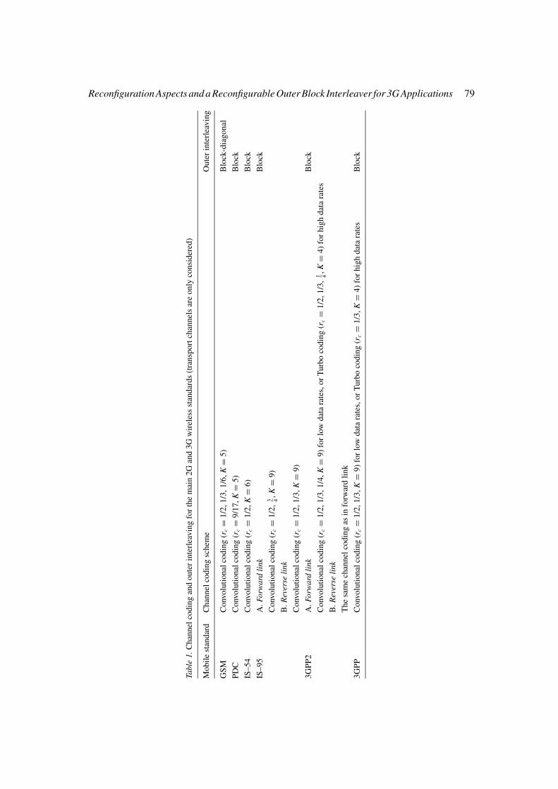
Table 1 summarizes the channel coding and outer interleaving techniques that the most im-portant second and third generation of digital mobile radio standards use (K and rc correspondto the constraint length and the rate of the encoder, respectively): it is well known that thesecond generation (2G) standards support low input bit rates (Rb < 28.8 kbps), while the 3Gstandards support both low and high (Rb > 28.8 kbps) bit rates. The 2G standards consid-ered are GSM, IS-95, IS-54 and PDC [5], while the 3G standards are 3GPP [6] and 3GPP2[7].
2.2. SOFTWARE RADIO CONCEPT
The development of a large number of digital mobile radio standards around the world hasborn the idea of a common global standard, making attractive the software radio concept. Theidea was first introduced in [8] and it corresponds to software implementation of the mobileterminal, which is able to adapt dynamically to the radio environment (including changingto a different standard) wherever it is located. This means that software radio requires thatthe functionality of the radio interface is defined and implemented in software applying to allthree layers of the transceiver of the radio interface protocol: network, data link and physical
Reconfiguration Aspects and a Reconfigurable Outer Block Interleaver for 3G Applications 79
Tabl
e1.
Ch
ann
elco
din
gan
do
ute
rin
terl
eav
ing
for
the
mai
n2
Gan
d3
Gw
irel
ess
stan
dar
ds
(tra
nsp
ort
chan
nel
sar
eo
nly
con
sid
ered
)
Mo
bil
est
and
ard
Ch
ann
elco
din
gsc
hem
eO
ute
rin
terl
eav
ing
GS
MC
onv
olu
tio
nal
cod
ing
(rc=
1/2
,1
/3,
1/6
,K
=5
)B
lock
-dia
go
nal
PD
CC
onv
olu
tio
nal
cod
ing
(rc=
9/1
7,
K=
5)
Blo
ck
IS–
54
Co
nvo
luti
on
alco
din
g(r
c=
1/2
,K
=6
)B
lock
IS–
95
A.
Forw
ard
link
Blo
ck
Co
nvo
luti
on
alco
din
g(r
c=
1/2
,3 4,
K=
9)
B.
Rev
erse
link
Co
nvo
luti
on
alco
din
g(r
c=
1/2
,1
/3,
K=
9)
3G
PP
2A
.Fo
rwar
dli
nkB
lock
Co
nvo
luti
on
alco
din
g(r
c=
1/2
,1
/3,
1/4
,K
=9
)fo
rlo
wd
ata
rate
s,o
rT
urb
oco
din
g(r
c=
1/2
,1
/3,
1 4,
K=
4)
for
hig
hd
ata
rate
s
B.
Rev
erse
link
Th
esa
me
chan
nel
cod
ing
asin
forw
ard
lin
k
3G
PP
Co
nvo
luti
on
alco
din
g(r
c=
1/2
,1
/3,
K=
9)
for
low
dat
ara
tes,
or
Tu
rbo
cod
ing
(rc=
1/3
,K
=4
)fo
rh
igh
dat
ara
tes
Blo
ck
80 C. Chaikalis
layer. The use of software for the representation of transceiver functionality corresponds tothe use of digital signal processors, which will replace the dedicated hardware of conventionaltransceivers, in order to run the software in real time [9]. In other words and according to[10], the aim of software radio is to build flexible radio systems, multi-service, multi-standard,multi-band, reconfigurable and reprogrammable by software.
2.3. RECONFIGURATION CONCEPT
As was mentioned in Section 1, the reconfiguration concept represents specific functionalitiesin any of the three layers of the radio interface protocol in a mobile transceiver. We considerpossible reconfigurability in the physical layer of the radio interface. Particularly, focusingon the functions of channel coding and outer interleaving, two types of reconfiguration canbe defined: between different standards and within a single standard [11]. Each of these twotypes is further explored below.
2.3.1. Reconfiguration Between Different StandardsThis type of reconfiguration involves common functionalities or operations of the radiotransceiver chain between different mobile standards operating world-wide in order to achieveinteroperability in a single terminal. As can be seen in Table 1, possible reconfigurable func-tionalities can be found among the different standards: in a general reconfigurable 2G/3Gtransceiver architecture considering channel encoding and outer interleaving functions, thefollowing example sub-architectures can be identified:
• 3GPP2/3GPP for Rb < 28.8 kbps: A possible reconfigurable transceiver architecture (asconsidered in [12]) consists of a convolutional encoder/Viterbi decoder with rate rc =1/3 and constraint length K = 9 and an outer block interleaver-deinterleaver with twocolumns.
• 3GPP2/3GPP for Rb > 28.8 kbps: Here, a reconfigurable transceiver architecture includesa turbo encoder/decoder with rate rc = 1/3 and K = 4 and the same outer block interleaver-deinterleaver for both standards [11]. In this case the reconfigurable architecture will havethe same constituent encoders, but two different inner interleavers for the turbo encoder.Similarly, the turbo decoder will have the same SISO decoders for both standards, butdifferent interleavers-deinterleavers.
• GSM/3GPP: In [13] a general reconfigurable transceiver approach is evaluated. It is shownthat in the reconfigurable transmitter architecture, one of the two constituent encoders ofthe turbo encoder for 3GPP can be used as the GSM convolutional encoder. Similarly, oneof the two SISO decoders of the turbo decoder can be used as the GSM decoder. The onlyproblem in this reconfigurable architecture is that GSM has to use a recursive systematicconvolutional code instead of non-systematic convolutional with different constraint lengthK, according to Table 1.
• IS-95/3GPP2 for Rb < 28.8 kbps: A possible reconfigurable transceiver architecture consistsof a convolutional encoder/Viterbi decoder with rate rc = 1/2 and constraint length K = 9 forboth links or for rc = 1/3 and the same K for the reverse link, with the same outer interleaver-deinterleaver for both standards [11].
• IS-95/3GPP for Rb < 28.8 kbps: In this case a possible reconfigurable transceiver consistsof a convolutional encoder/Viterbi decoder with rc = 1/2 and K = 9, again with the sameouter interleaving/deinterleaving [11].
Reconfiguration Aspects and a Reconfigurable Outer Block Interleaver for 3G Applications 81
2.3.2. Reconfiguration within a Single StandardThe second reconfiguration type deals with possible reconfigurability within a single mobilestandard, which means the adjustment of the parameters of a radio transceiver function accord-ing to specific operating conditions and parameters. An example, which belongs in this categoryconsidering the function of channel coding-decoding, is the reconfigurable SOVA/log-MAPturbo decoder. Its description and implementation at the 3GPP mobile standard is discussedin [11, 14].
In this contribution we focus on the second type of reconfiguration, particularly within thephysical layer, and we consider the function of outer interleaving: a reconfigurable outer blockinterleaver-deinterleaver over correlated Rayleigh fading is introduced for the 3GPP mobilestandard: the number of columns of the outer interleaver-deinterleaver is adjusted accordingto the operating environment, the frame length and the corresponding performance. Thus, tworeconfigurable blocks can be identified in the mobile transceiver (interleaver-deinterleaver).An initial approach to this idea has been done in [15, 16].
3. Turbo Decoder
At the receiver, for time instant (or symbol) k, the noisy received symbol sequence at the turbodecoder is for a turbo code with rate rc = 1/3: yk = {y(0)
k , y(p)k } = y(0)
1 , y(p)1 , y(0)
2 , y(p)2 . . . , y(0)
k f,
y(p)k f
, where y(0)k and y(p)
k represent the noisy received systematic and parity symbols and p =1,2 for first and second decoder, respectively. This sequence must be multiplied by the chan-nel reliability value 4 · ak · rc · Eb
N0, as shown in [17]. Hence, the weighted received sequence
rk = {r (0)k , r (p)
k } = r (0)1 , r (p)
1 , r (0)2 , r (p)
2 , . . . , r (0)k f
, r (p)k f
is given by: rk = 4 · ak · rc · EbN0
· yk
where ak represents the mobile channel fading amplitude sequence and Eb/N0 is the SNR.The symbols r (0)
k and r (p)k correspond to the weighted received systematic and parity symbols,
respectively.
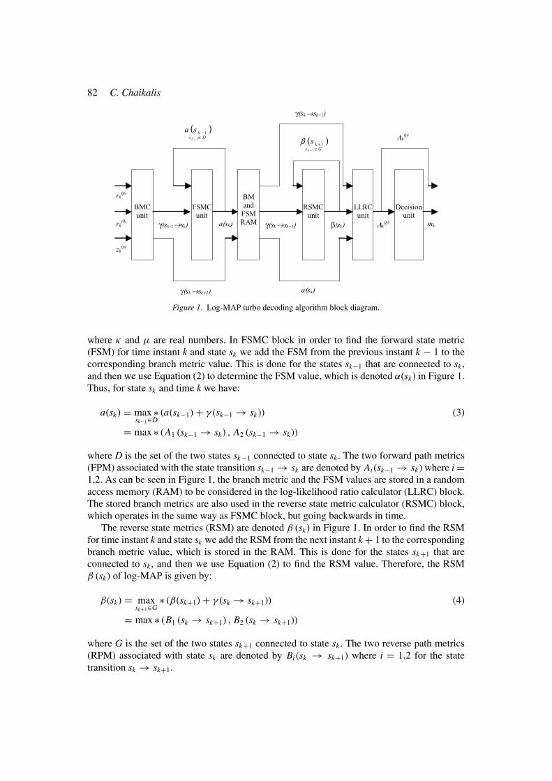
3.1. LOG-MAP DESCRIPTION
The block diagram of log-MAP algorithm, which is used in each of the two SISO decoders ofthe turbo decoder, is presented in Figure 1 [3, 18, 19]. The branch metric calculator (BMC)unit provides the branch metrics (which are denoted BM in Figure 1) and each SISO decoderhas three inputs: the a-priori information symbol z(p)
k (p = 1 or 2 for first or second decoder,respectively) and the weighted received sequence rk . The branch metrics γ (sk−1 → sk) foreach SISO decoder are calculated as follows:
For SISO decoder 1 : γ (sk−1 → sk) = x (0)k
(z(1)
k + r (0)k
) + x (1)k · r (1)
k
For SISO decoder 2 : γ (sk−1 → sk) = x (0)k (z(2)
k + r ′(0)k ) + x (2)
k · r (2)k
(1)
where for the state transition sk−1 → sk and time instant k, x (0)k and x (p)
k correspond to thesystematic and the parity output symbols of the recursive systematic convolutional turboencoder and r ′(0)
k is the interleaved systematic symbol.Before analyse the operation of forward state metric calculator (FSMC) block, let us first
show the Jacobian logarithm operation (also called E operation in [18]):
κ Eμ = max ∗(κ, μ) = − ln(e−κ + e−μ) = ln (eκ + eμ) (2)
= max ∗ (κ, μ) + ln (1 + e−|κ−μ|)
82 C. Chaikalis
BMC unit
FSMC unit
LLRC unit
Decision unit
γ(sk-1→sk) Λk(p) mk
BM and
FSM RAM a(sk) β(sk) γ(sk→sk+1)
γ(sk→sk+1)
γ(sk→sk+1)
a(sk)
( )Ds
kk
sa∈
−− 1
1
Λk(p)
( )Gs
kk
s∈
++1
1β
RSMC unit
rk(p)
rk(0)
zk(p)
Figure 1. Log-MAP turbo decoding algorithm block diagram.
where κ and μ are real numbers. In FSMC block in order to find the forward state metric(FSM) for time instant k and state sk we add the FSM from the previous instant k − 1 to thecorresponding branch metric value. This is done for the states sk−1 that are connected to sk ,and then we use Equation (2) to determine the FSM value, which is denoted α(sk) in Figure 1.Thus, for state sk and time k we have:
a(sk) = max ∗sk−1∈D
(a(sk−1) + γ (sk−1 → sk)) (3)
= max ∗ (A1 (sk−1 → sk) , A2 (sk−1 → sk))
where D is the set of the two states sk−1 connected to state sk . The two forward path metrics(FPM) associated with the state transition sk−1 → sk are denoted by Ai (sk−1 → sk) where i =1,2. As can be seen in Figure 1, the branch metric and the FSM values are stored in a randomaccess memory (RAM) to be considered in the log-likelihood ratio calculator (LLRC) block.The stored branch metrics are also used in the reverse state metric calculator (RSMC) block,which operates in the same way as FSMC block, but going backwards in time.
The reverse state metrics (RSM) are denoted β (sk) in Figure 1. In order to find the RSMfor time instant k and state sk we add the RSM from the next instant k + 1 to the correspondingbranch metric value, which is stored in the RAM. This is done for the states sk+1 that areconnected to sk , and then we use Equation (2) to find the RSM value. Therefore, the RSMβ (sk) of log-MAP is given by:
β(sk) = maxsk+1∈G
∗ (β(sk+1) + γ (sk → sk+1)) (4)
= max ∗ (B1 (sk → sk+1) , B2 (sk → sk+1))
where G is the set of the two states sk+1 connected to state sk . The two reverse path metrics(RPM) associated with state sk are denoted by Bi (sk → sk+1) where i = 1,2 for the statetransition sk → sk+1.
Reconfiguration Aspects and a Reconfigurable Outer Block Interleaver for 3G Applications 83
LLRC block uses the stored branch metric and FSM values together with the RSM valuesto calculate the soft output or log-likelihood ratio (LLR) �
(p)k (p = 1,2 for first and second
decoder, respectively) at time instant k according to the following Equation [18, 19]:
�(p)k = max ∗
S1
(a(sk) + γ (sk → sk+1) + β(sk+1)) (5)
− max ∗S0
(a(sk) + γ (sk → sk+1) + β(sk+1))
where S1 and S0 are the sets of all state transitions sk → sk+1 associated with informationbit 1 and 0, respectively. Finally, either the decision unit outputs the binary sequence mk
after deinterleaving if the decoding process terminates, or the value of �(p)k is fed to the next
decoding stage for the same turbo decoding iteration (if the first SISO is used) or for anotheriteration (if the second SISO is used).
3.2. SCALING OF THE EXTRINSIC INFORMATION
It has to be mentioned that a factor s = 0.7 is used for scaling of the extrinsic information inthe turbo decoder since, according to [11], it gives performance improvement up to 0.25 dBfor log-MAP in a flat fading channel. Moreover, in [14] it is shown that for the 3GPP standard,using soft output Viterbi (SOVA) and log-MAP turbo decoding algorithms, the application ofa common scaling factor s = 0.7 in the calculation of the extrinsic information can improveperformance in channels with additive white Gaussian noise. Thus, the extrinsic informationsequence l (p)
k has to be multiplied by the scaling factor s for every time instant (or symbol)k:
l (p)k =
(�
(p)k
2− r (0)
k − z(p)k
)s (6)
4. Data Flow in 3GPP and Simulation Environment
In 3GPP mobile communications standard, the way that the data is transferred over the radiointerface from the Medium Access Control (MAC) sub-layer of data link layer to the physicallayer defines a transport channel, the characteristics of which are determined by its transportformat set [20]. This consists of different transport formats, specifying the physical layerprocessing to be applied to the particular transport channel. The transport formats must havethe same type of channel coding and time transmission interval (TTI), while the transportblock set (data frame) size can vary. The transport block set corresponds to the data exchangebetween the MAC and the physical layer, therefore determines the number of bits input to thechannel encoder. One transport block set can be transmitted every TTI, with possible valuesfor TTI of 10, 20, 40 and 80 ms.
After channel coding, outer block interleaving is performed, and since the frame durationin 3GPP is 10 ms, the number of columns of the outer block interleaver can be one, two,four or eight, depending on the value of TTI. Therefore, the TTI values and the number ofcolumns of the outer block interleaver are interrelated. Additionaly, every transport channel isassigned a radio bearer with a particular bit rate. A mobile terminal may use several parallel

84 C. Chaikalis
transport channels simultaneously, each having its own characteristics (transport format set).These transport channels are multiplexed onto the same physical channel [20].
4.1. MOBILE CHANNEL
It is well known that correlated Rayleigh fading channels can be divided into two categoriesdue to the relationship between the maximum delay (or delay spread) of the channel Tm and thesymbol period Ts : frequency selective channels and frequency flat fading channels. A channelbelongs to the first category if Tm > Ts , whereas if Tm < Ts the channel belongs to the secondcategory [21].
In this paper we focus on the flat Rayleigh fading channel model: its discrete representationis given by the following Equation:
yk = αk · xk + nk (7)
where k is an integer symbol index, xk is a binary phase shift keying (BPSK) symbol amplitude(±1) and nk is a Gaussian random variable. The fading amplitude ak is a sample from acorrelated Gaussian random process with zero mean and is generated using the Sum of Sinesor Jakes model, which is described in [22]. This model is based, as its name implies, onsumming 9 sinusoids whose frequencies are chosen as samples of the Doppler spectrum. Theproperties of Jakes model are further analysed in [23].
4.2. SIM ULATION PARAMETERS
Given a relative velocity υ between a base station and a mobile station, the resulting Dopplerfrequency fd is calculated from the following Equation [5]:
fd = υ
cfc (8)
where fc denotes the carrier frequency of the transmitted signal and c refers to the speed oflight.
For our simulation model a carrier frequency fc = 2 GHz is considered. It is also assumedthat 1,000,000 information bits are transmitted and grouped into frames whose length k f mustbe ≥ 40 and ≤ 5114, according to [6]. For a particular transport channel, every TTI the datawith the characteristics specified in a transport format of the transport channel (k f bits), isturbo encoded (constraint length K = 4 and rate rc = 1/3 according to [6]) at the transmitter.Furthermore, no tailing bit scheme is applied to the two recursive systematic convolutionalencoders of the turbo encoder: each time it is assumed that they start encoding from the all-zeros state. After turbo coding and block interleaving using the 3GPP parameters, the bits areBPSK modulated and transmitted through the mobile channel.
The receiver, after outer block deinterleaving and turbo decoding, outputs the bit sequencek f . Furthermore, the received values are not quantized; therefore floating point arithmeticis used. The receiver is also assumed to have exact estimates of the fading amplitudes (per-fect channel estimation without side information), while 8 iterations are used in the turbodecoder.
Reconfiguration Aspects and a Reconfigurable Outer Block Interleaver for 3G Applications 85
5. Outer Block Interleaving in Fading Environment
For wireless communication systems, turbo codes have been shown to provide impressivecoding gains in fading channels. Especially in flat Rayleigh fading channels, performance canbe greatly improved if outer block interleaving is used [3, 24]. Turbo encoding alone cannotcorrect the errors occurred in a correlated fading channel (which tend to be burst errors), sinceturbo codes are more effective with random errors, so outer block interleaving is essential.Obviously, the reason for using outer block interleaving is the spreading of burst errors.Furthermore, according to [3], perfect interleaving over a long period for a flat fading channelcan approximate the bit error rate (BER) performance of the uncorrelated Rayleigh fadingchannel. This is the reason that this type of channel is also described as “fully-interleaved flatRayleigh fading” in the literature.
In [25] it is shown that the number of columns is the critical parameter in the design of outerblock interleavers for turbo codes over flat Rayleigh fading channels. The higher the mobilespeed, the larger number of columns needed. In [26] simulation results are presented for thefour different 3GPP mobile standard block interleaver lengths (TTI) using flat Rayleigh fadingand convolutional coding. Only the coding rate is varied for a terminal speed υ = 50 km/h,a frame length k f = 504 bits and a bit rate Rb = 64 kbps. For these parameters and differentSNR, a TTI of 80 ms is shown to achieve the best FER performance. Similarly to [26], butfor turbo codes, in [16] we discuss the effect of outer block interleaving on 3GPP turbo codesperformance for a frame length of 5114 bits, SOVA and log-MAP algorithms and bit ratesRb = 28.8 and 128 kbps. As expected, for the first bit rate value the BER performance isbetter.
In [27] a reconfigurable outer block interleaver for block codes over flat Rayleigh fadingis presented. A formula is derived to calculate the interleaving depth according to the Dopplerfrequency fd . It is also mentioned that the BER will be higher unless the right number ofcolumns is employed. This is because burst errors, which occur due to correlated Rayleighfading environment, are spread into multiple uncorrectable frames destroying more bits, whichotherwise would be correct. In the following section it will be shown that we draw the sameconclusion for turbo codes.
6. Simulation Results and Optimum Block Interleaver Selection
For our simulations the input bit rate Rb, which is used in the calculation of the normalised faderate fdTs , is set to be 128 kbps. The corresponding symbol rate Rs is 384 Kbaud. Two differentscenarios are examined: a relatively small frame length of k f = 1000 bits and the maximumallowed frame length for 3GPP mobile standard of k f = 5114 bits. Furthermore, four differentmobile terminal speeds are considered for each scenario: 4 km/h (corresponds to indoor or lowrange outdoor operating environment), 50 and 100 km/h (urban or suburban outdoor operatingenvironment) and 300 km/h (rural outdoor operating environment). The BER and frame errorrate (FER) performances are evaluated for each scenario in order to find the optimum numberof columns of the outer block interleaver [11].
6.1. BER PERFORM ANCE
The simulation results showing the BER performance for the two different scenarios arepresented in the next sections.

86 C. Chaikalis
Figure 2. BER performance of 3GPP turbo code over a flat rayleigh fading channel with fd Ts = 0.000019 and
0.00024 using log-MAP for different outer block interleaver lengths, k f = 1000 bits, s = 0.7 and 8 iterations.
6.1.1. Scenario 1: k f = 1000 bitsFigure 2 presents the BER performance of the simulated system for mobile speeds of 4 and50 km/h. The corresponding normalised fade rates fdTs are 0.000019 and 0.00024, while theDoppler frequencies fd are calculated 7.4 and 92.5 Hz, respectively using Equation (8). ForfdTs = 0.000019 and at a BER of 2 × 10⁻³, there is a gain of 1.8 dB for a TTI transition from10 to 20 ms, while for fdTs = 0.00024 and at a BER of 10−3 for the same TTI transition thegain is larger, 5 dB. Thus, for both normalised fade rates, the optimum TTI value (or blockinterleaver length) is 20 ms: there is no BER performance improvement for larger TTI values.On the contrary, for fdTs = 0.00024, BER performance becomes worse for values larger thanthe optimum value of 20 ms: at a BER of 3 × 10⁻⁴, 1 dB performance loss can be observedfor 40 and 80 ms compared to the optimum TTI value of 20 ms.
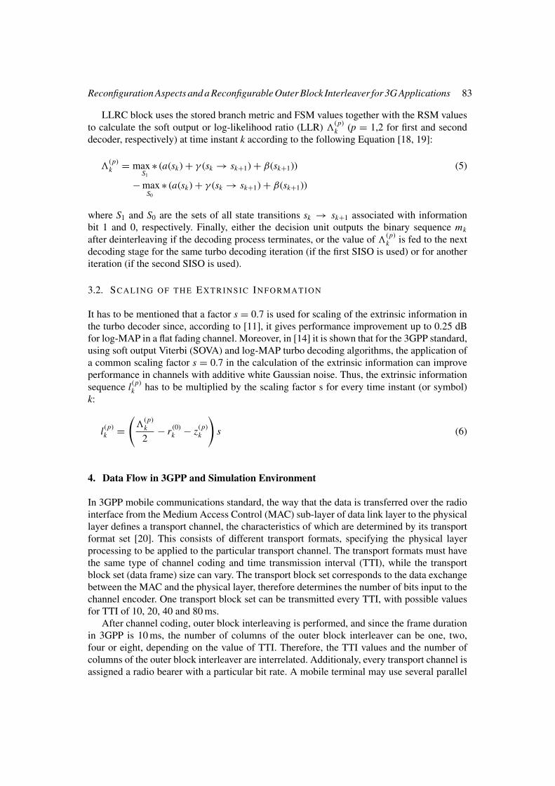
For Figure 3 the mobile speeds are 100 and 300 km/h, whereas the corresponding nor-malised fade rates fdTs are 0.00048 and 0.0014. The Doppler frequencies fd are 185.1 and555.5 Hz, respectively. For fdTs = 0.00048 the optimum TTI value is 40 ms. However, at aBER of 10−3 a gain of 6 and 0.85 dB is seen for a TTI transition from 10 to 20 and 20 to 40 ms,respectively. If we compare the performances of the optimum TTI value and the 80 ms at aBER of 2 × 10⁻⁴, a performance loss of 1 dB is seen, which is the same as the loss found forfdTs = 0.00024. For fdTs = 0.0014 it can be noticed that the maximum allowed TTI value of80 ms is optimum. Thus, at a BER of 10−3 a TTI increase from 10 to 20, 20 to 40 and 40 to80 ms gives performance gains of 5, 1.9 and 0.4 dB, respectively.
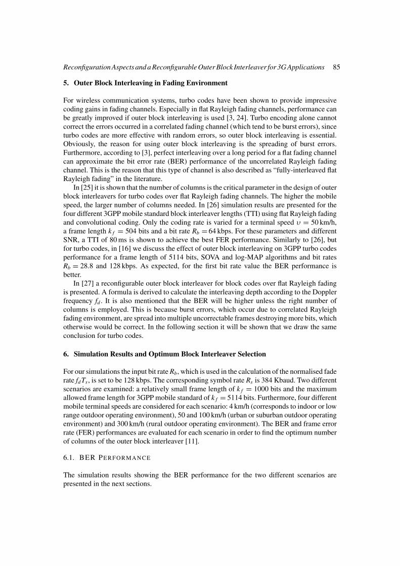
6.1.2. Scenario 2: k f = 5114 bitsConsidering a large frame length of 5114 bits, Figure 4 presents the BER performance ofthe simulated system for a normalised fade rate fdTs = 0.000019. As can be seen, 20 ms is
Reconfiguration Aspects and a Reconfigurable Outer Block Interleaver for 3G Applications 87
Figure 3. BER performance of 3GPP turbo code over a flat rayleigh fading channel with fd Ts = 0.00048 and
0.0014 using log-MAP for different outer block interleaver lengths, k f = 1000 bits, s = 0.7 and 8 iterations.
Figure 4. BER performance of 3GPP turbo code over a flat rayleigh fading channel with fd Ts = 0.000019 and
0.00024 using log-MAP for different outer block interleaver lengths, k f = 5114 bits, s = 0.7 and 8 iterations.

88 C. Chaikalis
Figure 5. BER performance of 3GPP turbo code over a flat rayleigh fading channel with fd Ts = 0.00048 and
0.0014 using log-MAP for different outer block interleaver lengths, k f = 5114 bits, s = 0.7 and 8 iterations.
the optimum interleaver length, while further increase of the TTI gives a performance loss of0.5 dB at a BER of 1.7 × 10⁻³. Furthermore, in Figure 4 we can see that for a normalised faderate fdTs = 0.00024, 40 ms is the optimal TTI choice. At a BER of 10−3, an increase of theTTI from 10 to 20 and 20 to 40 ms gives a gain of 8.7 and 2 dB, respectively. Again, a furtherincrease of the TTI (80 ms) can cause up to 0.4 dB performance loss at a BER of 6 × 10⁻⁴.
Figure 5 shows the BER performance of the system for a normalised fade rate fdTs =0.00048. The BER improves as the TTI increases. However, the optimum TTI value is 80 ms.Furthermore at a BER of 10−3, and for a TTI increase from 10 to 20, 20 to 40 and 40 to 80the gain is 7.4, 2 and 0.4 dB, respectively. Moreover, for a normalised fade rate fdTs = 0.0014and at the same BER, for a TTI increase from 10 to 20, 20 to 40 and 40 to 80 the gain is 6, 2and 0.7 dB, respectively. However, again the optimum TTI value is 80 ms.
6.2. FER PERFORM ANCE
The FER performance simulation results for the two different scenarios are presented below.
6.2.1. Scenario 1: k f = 1000 bitsFigure 6 illustrates the FER performance of the simulated system for normalised fade rates of0.000019 and 0.00024. For fdTs = 0.000019 it can be observed that for an increase of the TTIfrom 10 to 20 ms there is a gain of 6.8 dB at a FER of 10−1. For a further increase of the TTIno gain is seen. Therefore, a TTI of 20 ms is the optimum length. For fdTs = 0.00024 and atthe same FER, an increase of the TTI from 10 to 20 ms gives 10.5 dB gain, while an increasefrom 20 to 40 ms gives 2 dB gain. A further increase from 40 to 80 ms gives no gain. However,40 ms is enough to achieve the lowest possible FER.

Reconfiguration Aspects and a Reconfigurable Outer Block Interleaver for 3G Applications 89
Figure 6. FER performance of 3GPP turbo code over a flat rayleigh fading channel with fd Ts = 0.000019 and
0.00024 using log-MAP for different outer block interleaver lengths, k f = 1000 bits, s = 0.7 and 8 iterations
Figure 7. FER performance of 3GPP turbo code over a flat rayleigh fading channel with fd Ts = 0.00048 and 0.0014
using log-MAP for different outer block interleaver lengths, k f = 1000 bits, s = 0.7 and 8 iterations.
Figure 7 shows the FER for fdTs = 0.00048 and fdTs = 0.0014. In the same way as inthe previous two figures, for the first normalised fade rate value 40 ms is optimum, while forthe second 80 ms is the best choice. Furthermore, for fdTs = 0.00048 and at a FER of 10−1 aperformance gain of 9 and 3.9 dB is seen for an increase of the TTI from 10 to 20 and from
90 C. Chaikalis
Figure 8. FER performance of 3GPP turbo code over a flat rayleigh fading channel with fd Ts = 0.000019 and
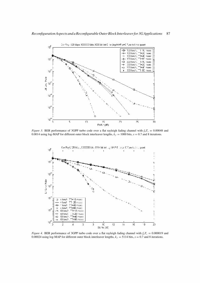
0.00024 using log-MAP for different outer block interleaver lengths, k f = 5114 bits, s = 0.7 and 8 iterations
20 to 40 ms, respectively. Similarly, for fdTs = 0.0014 at the same FER, a gain of 6.5, 3.4 and0.5 dB is seen for a TTI transition from 10 to 20, 20 to 40 and 40 to 80 ms, respectively.
6.2.2. Scenario 2: k f = 5114 bitsIn Figure 8 the FER performance of the simulated system is examined for fdTs = 0.000019 andfdTs = 0.00024. For the first value of the normalised fade rate and at a FER of 3 × 10⁻¹, it canbe noticed that for a TTI increase from 10 to 20 ms, there is a gain of 14.5 dB. It is clear thata TTI = 20 ms is enough to achieve the lowest FER. If the normalised fade rate is increasedto 0.00024 then 80 ms is the optimum solution. In this case, at a FER of 1.5 × 10⁻¹ for a TTIincrease from 10 to 20, 20 to 40 and 40 to 80 ms the gain is 10, 4.7 and 0.7 dB, respectively.
In Figure 9 the FER of the system for normalised fade rates of 0.00048 and 0.0014 isevaluated. For both values 80 ms is the optimum TTI. This is the expected value since theframe length and the normalised fade rate have very high values. Particularly for fdTs =0.00048, at a FER of 10−1 a performance gain of 9.3, 4.7 and 0.95 dB is seen for a TTIincrease from 10 to 20, 20 to 40 and 40 to 80 ms, respectively. Finally, for fdTs = 0.0014 atthe same FER, a performance gain of 6, 4 and 1.4 dB is seen for a TTI increase from 10 to 20,20 to 40 and 40 to 80 ms, respectively.
In order to summarise the above remarks Table 2 have been drawn. It corresponds to theoptimum TTI values (or outer block interleaver number of columns), which were observedthrough the BER and FER performance results for the different mobile terminal speeds andtwo scenarios for the frame length. However, as can be seen in Table 2 for both scenar-ios, as a compromise between lowest BER performance and complexity and for a constantbit-rate of 128 kbps, a TTI = 20 ms (block interleaver with 2 columns) is recommendedfor indoor or low range outdoor operating environments. For an urban or suburban outdoor
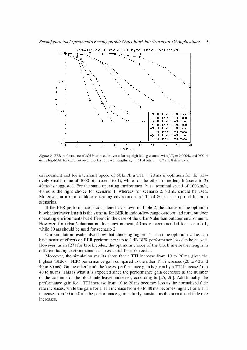
Reconfiguration Aspects and a Reconfigurable Outer Block Interleaver for 3G Applications 91
Figure 9. FER performance of 3GPP turbo code over a flat rayleigh fading channel with fd Ts = 0.00048 and 0.0014
using log-MAP for different outer block interleaver lengths, k f = 5114 bits, s = 0.7 and 8 iterations.
environment and for a terminal speed of 50 km/h a TTI = 20 ms is optimum for the rela-tively small frame of 1000 bits (scenario 1), while for the other frame length (scenario 2)40 ms is suggested. For the same operating environment but a terminal speed of 100 km/h,40 ms is the right choice for scenario 1, whereas for scenario 2, 80 ms should be used.Moreover, in a rural outdoor operating environment a TTI of 80 ms is proposed for bothscenarios.
If the FER performance is considered, as shown in Table 2, the choice of the optimumblock interleaver length is the same as for BER in indoor/low range outdoor and rural outdooroperating environments but different in the case of the urban/suburban outdoor environment.However, for urban/suburban outdoor environment, 40 ms is recommended for scenario 1,while 80 ms should be used for scenario 2.
Our simulation results also show that choosing higher TTI than the optimum value, canhave negative effects on BER performance: up to 1 dB BER performance loss can be caused.However, as in [27] for block codes, the optimum choice of the block interleaver length indifferent fading environments is also essential for turbo codes.
Moreover, the simulation results show that a TTI increase from 10 to 20 ms gives thehighest (BER or FER) performance gain compared to the other TTI increases (20 to 40 and40 to 80 ms). On the other hand, the lowest performance gain is given by a TTI increase from40 to 80 ms. This is what it is expected since the performance gain decreases as the numberof the columns of the block interleaver increases, according to [25, 26]. Additionally, theperformance gain for a TTI increase from 10 to 20 ms becomes less as the normalised faderate increases, while the gain for a TTI increase from 40 to 80 ms becomes higher. For a TTIincrease from 20 to 40 ms the performance gain is fairly constant as the normalised fade rateincreases.
92 C. Chaikalis
Table 2. Optimum TTI values for different scenarios and operating environments based on BER and FER
performance.
Optimum TTI value (ms)
BER performance FER performanceOperating Terminal speed Normalised fade
environment (km/h) rate fd Ts Scenario 1 Scenario 2 Scenario 1 Scenario 2
Indoor or low range outdoor 4 0.000019 20 20 20 20
Urban or suburban outdoor 50 0.00024 20 40 40 80
100 0.00048 40 80 40 80
Rural outdoor 300 0.0014 80 80 80 80
Table 3. fd TB values for different scenarios and mobile terminal speeds.
fd TB values
Terminal speed (km/h) Doppler frequency fd (Hz) Scenario 1 Scenario 2
4 7.4 0.05 0.3
50 92.5 0.7 3.7
100 185.1 1.4 7.4
300 555.5 4.3 22.2
7. Consideration of Frame Fade Duration
The duration of a data frame TB during the fading process is given from the following Equationaccording to [25]:
TB = Ts · k f
rc(9)
Assuming a bit rate Rb of 128 kbps and two scenarios for the frame length (scenario 1: k f =1000 bits and scenario 2: k f = 5114 bits), the frame duration TB is calculated using Equation(9), 7.8 and 39.9 ms, respectively. As expected, TB is proportional to k f . For these two TB valuesand the corresponding Doppler frequencies fd for the four typical terminal speeds consideredin Table 2, the product fdTB can be calculated (similarly to [25]) for both scenarios, as shownin Table 3.
For the different fdTB values of Table 3 different simulation results are presented below,showing the BER and FER performance for the different TTI values. It is assumed that theSNR is constant and equal to 6 dB [11].
7.1. BER PERFORM ANCE
For Figure 10 (scenario 1) it is obvious that for the SNR chosen, 40 ms is the optimumTTI value. Similarly to Section 6, a further TTI increase causes performance degradation.Furthermore, as fdTB increases the BER performance improves for all the TTI values. ForFigure 11 (scenario 2) it is noticed that as the frame length and fdTB increase, the BER
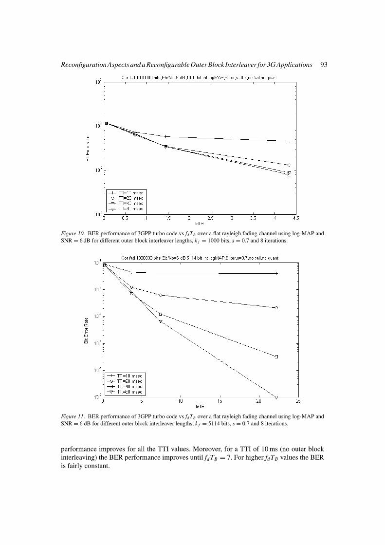
Reconfiguration Aspects and a Reconfigurable Outer Block Interleaver for 3G Applications 93
Figure 10. BER performance of 3GPP turbo code vs fd TB over a flat rayleigh fading channel using log-MAP and
SNR = 6 dB for different outer block interleaver lengths, k f = 1000 bits, s = 0.7 and 8 iterations.
Figure 11. BER performance of 3GPP turbo code vs fd TB over a flat rayleigh fading channel using log-MAP and
SNR = 6 dB for different outer block interleaver lengths, k f = 5114 bits, s = 0.7 and 8 iterations.
performance improves for all the TTI values. Moreover, for a TTI of 10 ms (no outer blockinterleaving) the BER performance improves until fdTB = 7. For higher fdTB values the BERis fairly constant.
94 C. Chaikalis
Figure 12. FER performance of 3GPP turbo code vs fd TB over a flat rayleigh fading channel using log-MAP and
SNR = 6 dB for different outer block interleaver lengths, k f = 1000 bits, s = 0.7 and 8 iterations.
Figure 13. FER performance of 3GPP turbo code vs fd TB over a flat rayleigh fading channel using log-MAP and
SNR = 6 dB for different outer block interleaver lengths, k f = 5114 bits, s = 0.7 and 8 iterations.
7.2. FER PERFORM ANCE
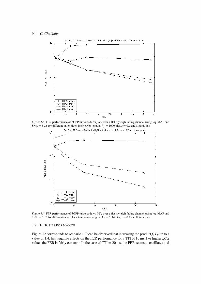
Figure 12 corresponds to scenario 1. It can be observed that increasing the product fdTB up to avalue of 1.4, has negative effects on the FER performance for a TTI of 10 ms. For higher fdTB
values the FER is fairly constant. In the case of TTI = 20 ms, the FER seems to oscillates and
Reconfiguration Aspects and a Reconfigurable Outer Block Interleaver for 3G Applications 95
stabilises as fdTB increases. For the other two TTI values the FER improves as fdTB increasesand 80 ms gives the best improvement. Moreover, FER is almost the same until fdTB = 1.4 for40 and 80 ms. For larger fdTB values a TTI of 80 ms gives better FER performance. For Figure13 (scenario 2) the observations are similar, but we see now that outer block interleaving hasa higher influence on the FER (better performance) for 40 and 80 ms.
However, it is interesting to note that as the frame length and fdTB increase, the FERperformance of 10 and 20 ms becomes worse. On the other hand, 40 and 80 ms give a betterFER. In other words, a TTI transition from 10 to 20 ms gives a fairly constant FER performancegain, while a TTI transition from 20 to 40 and 40 to 80 ms shows higher FER performancegain as the frame length and fdTB increase.
8. Discussion and Conclusions
Software radio and reconfiguration concepts are similar: they represent reconfigurable func-tionalities of the physical layer. We focus on the radio interface of the physical layer and weidentify two reconfiguration categories: between different mobile standards and within them.
This paper focuses on possible forms of reconfiguration in the case of an outer blockinterleaver/deinterleaver for turbo codes, in the context of 3G mobile communications. In thecase of fading operating environments, four possible outer block interleaver configurationshave been specified for 3GPP mobile communications standard. It is well known that thelarger the interleaver, the better performance we get, but the fading operating environment(mobile terminal speed) plays a critical role. This means that according to the operatingenvironment an increase of the outer interleaver length causes no performance improvementand sometimes can even decrease it. However, in this contribution a reconfigurable outerblock interleaver/deinterleaver is proposed for a constant data rate and the reconfigurationis controlled from parameters such as fading operating environment, performance and framelength. The question that arises is: “What are the benefits of using such a reconfigurablearchitecture?”. The answer is given below:
• Complexity and latency can be reduced and significant processing power consumption canbe saved if the outer block interleaver can reconfigure itself and choose the optimal numberof columns for each application: the latency savings are very important, especially in thecase of real time services with tight delay constraints.
• Negative performance effects would be avoided.
Our simulation results have shown that for indoor or low range outdoor operating environmentsthe outer block interleaver should have two columns, while in the case of a rural outdoorenvironment should have the maximum value of eight columns irrespective of other parameters.Moreover, for an urban or suburban outdoor operating environment the choice of the optimuminterleaver length depends on the two remaining parameters, namely performance and framelength.
At the last part of this paper, we discussed the influence of the product of the Dopplerfrequency with the frame fade duration (fdTB) on the performance of turbo codes for differentframes and outer block interleaver lengths (number of columns) and a constant SNR value.For 3GPP mobile communications standard our simulation results have shown that, the largerthe outer block interleaver length, the better performance we get as the frame length and theproduct fdTB increases, except for small frame lengths. Another exception occurs in terms of
96 C. Chaikalis
FER performance, which becomes worse for small outer block interleaver lengths (one andtwo columns).
References
1. C. Berrou, A. Glavieux and P. Thitimajshima, “Near Shannon Limit Error-Correcting Coding and Decoding:
Turbo-codes”, in Proceedings of ICC ’93, Geneva, Switzerland, IEEE, pp. 1064–1070, 1993.
2. A. Burr, “Turbo-Codes: the Ultimate Error Control Codes?”, IEE Electronics and Communication EngineeringJournal, Vol. 13, No. 4, pp. 155–165, August 2001.
3. J. Woodard and L. Hanzo, “Comparative Study of Turbo Decoding Techniques: An Overview”, IEEE Trans-actions on Vehicular Technology, Vol. 49, No. 6, pp. 2208–2233, November 2000.
4. F. Riera-Palou, C. Chaikalis and J. M. Noras, “Reconfigurable Mobile Terminal Requirements for Third
Generation Applications”, in Proceedings of Colloquium on UMTS Terminals and Software Radio, Glasgow,
UK, IEE, pp. 9/1–9/6, 1999.
5. R. Steele and L. Hanzo, Mobile Radio Communications, 2nd Edition, Pentech Press, London, 2000.
6. 3GPP TS 25.212 V3.9.0, Multiplexing and Channel Coding (FDD), Release 1999, March 2002.
7. 3GPP2 C.S0002-A V6.0, “Physical Layer Standard for cdma2000 Spread Spectrum Systems”, Release A,
February 2002.
8. J. Mitola, “The Software Radio Architecture”, IEEE Communications Magazine, Vol. 33, No. 5, May 1995.
9. W. Tuttlebee, “Software Radio-Impacts and Implications”, in Proceedings of 5th Intern. Symposium on SpreadSpectrum Techniques and Applications, Sun City, South Africa, IEEE, pp. 541–545, 1998.
10. F. Muratore, UMTS: Mobile Communications for the Future, J. Wiley & Sons, Chichester, 2001.
11. C. Chaikalis, Reconfigurable Structures for Turbo Codes in 3G Mobile Radio Transceivers, PhD thesis, School
of Engineering Design and Technology, University of Bradford, Bradford, UK, March 2003.
12. R. Machauer, A. Wiesler and F. Jondral, “Comparison of UTRA-FDD and Cdma2000 with Intra and Intercell
Interference”, in Proceedings of 6th International Symposium on Spread Spectrum Techniques and Applica-tions, New Jersey, USA, IEEE, pp. 652–656, 2000.
13. A. Wiesler and F.K. Jondral, “A Software Radio for Second and Third Generation Mobile Systems”, IEEETransactions on Vehicular Technology, Vol. 51, No. 4, pp. 738–748, July 2002.
14. C. Chaikalis and J.M. Noras, “Reconfigurable Turbo Decoding for 3G Applications”, Elsevier Signal Process-ing Journal, Vol. 84, No. 10, pp. 1957–1972, October 2004.
15. C. Chaikalis, J.M. Noras and F. Riera-Palou, “Reconfigurable Outer Block Interleaving Over Correlated
Rayleigh Fading for 3GPP Turbo Coding”, in Proceedings of WCNC’03, New Orleans, USA, IEEE, 2003, pp.
294–299.
16. C. Chaikalis, F. Riera-Palou and J.M. Noras, “Effect of Outer Block Interleaving in Turbo Codes Performance
Over Rayleigh Fading Channels for 3GPP”, in Proceedings of PIMRC 0̀2, Lisbon, Portugal, IEEE, pp. 374–379,
2002.
17. J. Hagenauer, “Iterative Decoding of Binary and Convolutional Codes”, IEEE Transactions on InformationTheory, Vol. 42, pp. 429–445, March 1996.
18. S. Pietrobon, “Implementation and Performance of a Turbo/MAP Decoder”, International Journal of SatelliteCommunications, Vol. 16, No. 1, pp. 23–46, 1998.
19. P. Robertson, E. Villebrun and P. Hoeher, “A Comparison of Optimal and Sub-Optimal MAP decoding algo-
rithms operating in the log domain”, in Proceedings of ICC ’95, Seattle, USA, IEEE, pp. 1009–1013, 1995.
20. H. Holma and A. Toskala, WCDMA for UMTS: Radio Access for Third Generation Mobile Communications,
J. Wiley & Sons, Chichester, pp. 85–113, 2000.
21. B. Sklar, Digital Communications: Fundamentals and Applications, 2nd Edition, Prentice Hall, New Jersey,
2001.
22. W. C. Jakes, Microwave Mobile Communications, J. Wiley & Sons, New York, 1974.
23. M. Patzold, U. Killat, F. Laue and Y. Li, “On the Statistical Properties of Deterministic Simulation Models for
Mobile Fading Channels”, IEEE Transactions on Vehicular Technology, Vol. 47, No. 1, pp. 254–269, February
1998.
24. E. Hall and S. Wilson, “Design and Analysis of Turbo Codes on Rayleigh Fading Channels”, IEEE Journalon Selected Areas in Communications, Vol. 16, No. 2, pp. 160–174, February 1998.
Reconfiguration Aspects and a Reconfigurable Outer Block Interleaver for 3G Applications 97
25. K. Tang, P.H. Siegel and L.B. Milstein, “On the Performance of Turbo Coding for the Land Mobile Channel
with Delay Constraints”, In Proceedings of 33rd Signals, Systems and Computers Asilomar conference, IEEE,
pp. 1659–1664, 1999.
26. F. Poppe, D. De Vleeschauwer and G. Petit, “Guaranteeing Quality of Service to Packetised Voice Over the
UMTS Air Interface”, In Proceedings of 8th International Workshop on QoS, Pittsburgh, USA, IEEE, pp.
85–91, 2000.
27. K.I. Chan and J.C. Chuang, “Required Interleaving Depth in Rayleigh Fading Channels”, In Proceedings ofGLOBECOM’96, London, UK, IEEE, pp. 1417–1421, 1996.
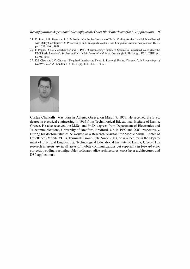
Costas Chaikalis was born in Athens, Greece, on March 7, 1973. He received the B.Sc.degree in electrical engineering in 1995 from Technological Educational Institute of Lamia,Greece. He also received the M.Sc. and Ph.D. degrees from Department of Electronics andTelecommunications, University of Bradford, Bradford, UK in 1999 and 2003, respectively.During his doctoral studies he worked as a Research Assistant for Mobile Virtual Center ofExcellence (Mobile VCE), Terminals Group, UK. Since 2003, he is a lecturer in the Depart-ment of Electrical Engineering, Technological Educational Institute of Lamia, Greece. Hisresearch interests are in all areas of mobile communications but especially in forward errorcorrection coding, reconfigurable (software radio) architectures, cross layer architectures andDSP applications.
Related Documents