Recommended Practice Approved November 30, 1997 Recommended Practice for Classification of Locations for Electrical Installations Classified as Class I, Zone 0, Zone 1, or Zone 2

Welcome message from author
This document is posted to help you gain knowledge. Please leave a comment to let me know what you think about it! Share it to your friends and learn new things together.
Transcript

ISA-RP12.24.01-1998 (IEC 79-10 Mod)
Approved November 30, 1997
Recommended Practice
Recommended Practice for
Classification of Locations for
Electrical Installations
Classified as Class I,
Zone 0, Zone 1, or Zone 2
ISA-RP12.24.01 (IEC 79-10 Mod), Recommended Practice for Classification of Locations for Electrical Installations Classified as Class I, Zone 0, Zone 1, or Zone 2
ISBN: 1-55617-649-X
Copyright 1998 by the Instrument Society of America. All rights reserved. Printed in the United States of America. No part of this publication may be reproduced, stored in a retrieval system, or transmitted, in any form or by any means (electronic, mechanical, photocopying, recording, or otherwise), without the prior written permission of the Publisher.
ISA67 Alexander DriveP. O. Box 12277Research Triangle Park, North Carolina 27709

Preface
This ISA recommended practice is based on IEC Publication 79-10. It is the intention of the ISA SP12 Committee to develop an ISA Recommended Practice that is harmonized with IEC 79-10 to the fullest extent possible.
This preface, as well as all footnotes and annexes, is included for informational purposes and is not part of ISA-RP12.24.01 (IEC 79-15 Mod).
This recommended practice has been prepared as part of the service of ISA, the international society for measurement and control, toward a goal of uniformity in the field of instrumentation. To be of real value, this document should not be static, but should be subject to periodic review. Toward this end, the Society welcomes all comments and criticisms, and asks that they be addressed to the Secretary, Standards and Practices Board; ISA; 67 Alexander Drive; P. O. Box 12277; Research Triangle Park, NC 27709; Telephone (919) 549-8411; Fax (919) 549-8288; E-mail: [email protected].
The ISA Standards and Practices Department is aware of the growing need for attention to the metric system of units in general, and the International System of Units (SI) in particular, in the preparation of instrumentation standards, recommended practices, and technical reports. The Department is further aware of the benefits to U.S. users of ISA standards of incorporating suitable references to the SI (and the metric system) in their business and professional dealings with other countries. Toward this end, this Department will endeavor to introduce SI-acceptable metric units in all new and revised standards to the greatest extent possible. Standard for Use of the International System of Units (SI): The Modern Metric System, published by the American Society for Testing & Materials as IEEE/ASTM SI 10-97, and future revisions, will be the reference guide for definitions, symbols, abbreviations, and conversion factors.
It is the policy of ISA to encourage and welcome the participation of all concerned individuals and interests in the development of ISA standards. Participation in the ISA standards-making process by an individual in no way constitutes endorsement by the employer of that individual, of the ISA, or of any of the standards, recommended practices, and technical reports that ISA develops.
CAUTION—THE USE OF THIS STANDARD, RECOMMENDED PRACTICE, ORTECHNICAL REPORT MAY INVOLVE HAZARDOUS MATERIALS, OPERATIONS OREQUIPMENT. THE STANDARD, RECOMMENDED PRACTICE, OR TECHNICALREPORT CANNOT ANTICIPATE ALL POSSIBLE APPLICATIONS OR ADDRESSALL POSSIBLE SAFETY ISSUES ASSOCIATED WITH USE IN HAZARDOUSCONDITIONS.
THE USER OF THIS STANDARD, RECOMMENDED PRACTICE, OR TECHNICALREPORT MUST EXERCISE SOUND PROFESSIONAL JUDGMENT CONCERNINGITS USE AND APPLICABILITY UNDER THE USER’S PARTICULARCIRCUMSTANCES. THE USER MUST ALSO CONSIDER THE APPLICABILITY OFANY GOVERNMENTAL REGULATORY LIMITATIONS AND ESTABLISHED SAFETYAND HEALTH PRACTICES BEFORE IMPLEMENTING THIS STANDARD,RECOMMENDED PRACTICE, OR TECHNICAL REPORT.
ISA-RP12.24.01-1998 (IEC 79-10 Mod) 3

ADDITIONALLY, IMPLEMENTATION OF THE STANDARD, RECOMMENDEDPRACTICE, OR TECHNICAL REPORT MAY REQUIRE USE OF TECHNIQUES,PROCESSES, OR MATERIALS COVERED BY PATENT RIGHTS. ISA TAKES NOPOSITION ON THE EXISTENCE OR VALIDITY OF ANY PATENT RIGHTS WHICHMAY BE INVOLVED IN IMPLEMENTING THE STANDARD, RECOMMENDEDPRACTICE, OR TECHNICAL REPORT. ISA WILL NOT BE RESPONSIBLE FORIDENTIFYING ALL PATENTS THAT MAY REQUIRE A LICENSE BEFOREIMPLEMENTATION OF THE STANDARD, RECOMMENDED PRACTICE, ORTECHNICAL REPORT OR FOR INVESTIGATING THE VALIDITY OR SCOPE OFANY PATENTS BROUGHT TO ITS ATTENTION. THE USER SHOULD CAREFULLYINVESTIGATE RELEVANT PATENTS BEFORE USING THE STANDARD,RECOMMENDED PRACTICE, OR TECHNICAL REPORT FOR THE USER’SINTENDED APPLICATION.
The following members of ISA SP12.24 contributed to the development of this document:
NAME COMPANY
A. Ballard, Chairman Crouse-Hinds Division of Cooper Ind.N. Abbatiello Eastman Kodak Co.D. Ankele Underwriters Laboratories Inc.S. Arnold Drexelbrook Engineering Co.D. Bishop Chevron USA Production CompanyP. Dobler Weidmuller Inc.W. Fiske Intertek Testing ServicesD. Jagger HAWKE AmericaB. Larson Turck Inc.W. Lawrence Factory Mutual Research Corp.R. Masek Bailey Controls Inc.D. Mohla Union Carbide Chem. and PlasticsJ. Propst Shell Oil Products CompanyC. Sawyer MI Cable Co., Inc.D. Wechsler Union Carbide Corporation
The following people served as members of ISA Committee SP12:
NAME COMPANY
*F. McGowan, Chairman Factory Mutual Research Corp.*D. Bishop, Managing Director Chevron USA Production Company*N. Abbatiello Eastman Kodak CompanyB. Apel MSA InstrumentS. Arnold Drexelbrook Engineering Company*P. Babiarz Crouse-Hinds Company*A. Ballard Crouse-Hinds CompanyG. Bentinck Dupont Engineering*R. Berthold Compression Systems Inc.H. Bockle Killark/Stahl Inc.K. Boegli Phoenix Contact Inc.J. Bossert Hazloc, Inc.R. Brodin Fisher Controls International, Inc.M. Buettner Ralston Purina CompanyR. Buschart PC & E, Inc.
4 ISA-RP12.24.01-1998 (IEC 79-10 Mod)

*W. Calder III Calder Enterprises.R. Cardinal Bently Nevada Corp.C. Casso Schlumberger Oil Field ServicesR. Castillo Industrias Venoco CAJ. Cawley US Dept of the InteriorH. Conner Congorhar Inc.M. Coppler Ametek Inc.J. Cospolich Waldemar S. Nelson & Company, Inc.J. Costello Henkel Corp.*E. Cranch Drexelbrook Engineering CompanyA. Czyz INERISW. Dill DMTP. Dobler Weidmuller Inc.T. Dubaniewicz Jr. Pittsburgh Research LaboratoryU. Dugar Mobil Chemical CompanyR. Ellis Servomex Co.A. Engler Appleton ElectricT. Feindel R. Stahl, Inc.W. Fiske Intertek Testing ServicesS. Florence Motorola Inc.G. Garcha PCS EngineeringE. Geissler Bartec US Corp.B. Gibson ABB Kent-Taylor Inc.J. Greenwald Huntsman Corp.L. Hamman U. S. Coast GuardE. Henning Bailey Fischer & PorterD. Hohenstein Pepperl + FuchsC. Hoy O-Z/Gedney*D. Jagger Hawke AmericaX. Jianping Shanghai Institute of Process Automation Instr.D. Kaplan Phoenix Mecano*P. Kelly Underwriters Laboratories, Inc.F. Kent Honeywell Inc.G. Kozinski Symbol Technologies Inc.J. Kuczka KillarkB. Larson Turck Inc.*W. Lawrence Factory Mutual Research CorporationW. Leber Appleton ElectricT. Lewis Jr. Applied Automation Inc.*N. Ludlam Factory Mutual Research Corp.V. Maggioli Feltronics Corp.*E. Magison Consultant*F. Maltby Drexelbrook Engineering CompanyR. Masek Bailey Controls CompanyD. McDermott Dexion HouseI. McMurchie Petromarine of Texas*R. McNeal Hawke AmericaJ. Miller Detector Electronics Corp.*A. Mobley 3M CompanyM. Morrow Data InstrumentsW. Mueller Pepperl + Fuchs Inc.E. Nesvig ERDCO Engineering Corp.
ISA-RP12.24.01-1998 (IEC 79-10 Mod) 5

M. Oakes WAGO Corp.*E. Olson 3M CompanyC. Oudar ExLoc Corp.A. Page III MSHA Certification CenterR. Pellizze Intertek Testing ServicesJ. Propst Shell Development CompanyC. Sandberg Raychem Corp.C. Sawyer MI Cable Co Inc.J. Shaffer Endress+Hauser Co.T. Schnaare Rosemount, Inc.W. Shao Canadian Standards AssociationA. Stafford Foxboro CompanyD. Stevens Chevron USA Inc.*D. Styrcula Underwriters Laboratories Inc.J. Thomason Omni Industrial Systems Inc.P. Thurnherr Thuba Ltd.L. Truscott Motorola Inc.*P. Turner 3M CompanyT. Vu Milltronics Ltd.D. Wechsler Union Carbide Corp.R. Weinzler Consultant____________________________
* One vote per company
This standard was approved for publication by the ISA Standards and Practices Board on November 30, 1997.
NAME COMPANY
R. Webb, Vice President Pacific Gas & Electric CompanyH. Baumann H. D. Baumann & Associates, Ltd.D. Bishop Chevron USA Production CompanyP. Brett Honeywell, Inc.W. Calder III Calder EnterprisesM. Cohen Flexonics, Inc.H. Dammeyer Ohio State UniversityR. Dieck Pratt & WhitneyW. Holland Southern Company Services, Inc.H. Hopkins ConsultantA. Iverson Ivy OptiksK. Lindner Endress + Hauser GmbH V. Maggioli Feltronics Corp.T. McAvinew Instrumentation & Control Engineering ServicesA. McCauley, Jr. Chagrin Valley Controls, Inc.G. McFarland Honeywell Inc.E. Montgomery Fluor Daniel, Inc.D. Rapley Rapley Engineering ServicesR. Reimer Rockwell AutomationJ. Rennie Factory Mutual Research CorporationW. Weidman Parsons Energy and Chemical GroupJ. Weiss Electric Power Research InstituteJ. Whetstone National Institute of Standards & Technology
6 ISA-RP12.24.01-1998 (IEC 79-10 Mod)

M. Widmeyer, Carnegie-Mellon UniversityH.R. Wiegle Canus Corp.C. Williams Eastman Kodak CompanyG. Wood Graeme Wood ConsultingM. Zielinski Fisher•Rosemount Systems, Inc.
ISA-RP12.24.01-1998 (IEC 79-10 Mod) 7


Contents
Foreword .................................................................................................................................... 10
1 General ................................................................................................................................... 101.1 Scope ..................................................................................................................... 101.2 Normative References .......................................................................................... 111.3 Purpose ................................................................................................................... 12
2 Definitions and terms ........................................................................................................... 122.10 Explosive limits ..................................................................................................... 17
3 Safety and area classification .............................................................................................. 193.1 Safety p rinciples .................................................................................................... 193.2 Area classification objectives ............................................................................... 19
4 Area classification procedure .............................................................................................. 204.1 General .................................................................................................................... 204.2 Sources of release ................................................................................................. 204.3 Type of Zone ........................................................................................................... 224.4 Extent of Zone ........................................................................................................ 224.5 Extent of zone — General comments ................................................................... 25
5 Ventilation .............................................................................................................................. 255.1 General .................................................................................................................... 255.2 Main types of ventilation ....................................................................................... 255.3 Degree of ventilation .............................................................................................. 265.4 Availability of ventilation ....................................................................................... 26
6 Documentation ...................................................................................................................... 266.1 General .................................................................................................................... 266.2 Drawings, data sheets and tables ........................................................................ 27
Annex A (Informative) – Examples of sources of release .................................................... 29A.1 Process plants and facilities ................................................................................ 29A.2 Openings ................................................................................................................ 29
Annex B – (Informative) Ventilation ........................................................................................ 33B.1 Natural ventilation ................................................................................................. 33B.2 Artificial ventilation ............................................................................................... 34B.3 Degree of ventilation ............................................................................................. 35B.4 Assessment of degree of ventilation and its influence on the hazardous
area ........................................................................................................................ 35B.5 Availability of ventilation ...................................................................................... 39B.6 Practical guide ....................................................................................................... 40B.7 Calculations to ascertain the degree of ventilation ........................................... 41
Annex C (Informative) – Examples of hazardous area classification ................................. 49
Annex D (Informative) – Use of combustible gas detection equipment .............................. 73
Annex E (Informative) – United States major deviations ...................................................... 75
ISA-RP12.24.01-1998 (IEC 79-10 Mod) 9

Foreword
This recommended practice is a modification of IEC 79-10, Electrical Apparatus for Explosive Gas Atmospheres, Part 10: Classification of Hazardous Areas, normalized as an American National Standard, with additional material added as appendices specifically for the classification of locations for electrical installations classified as Class I, Zone 0, Zone 1, or Zone 2 Classification of hazardous areas. U.S. National Deviations are shown by strikeout through text deleted and underline under text added. There are five annexes in this recommended practice. All annexes are Informative and are not considered part of this recommended practice.
1 General
1.1 Scope
This part of IEC 79 ISA-RP12.24.01 is concerned with the classification of hazardous areas where flammable gas or vapor risks may arise, in order to permit the proper selection and installation of apparatus for use in such hazardous areas (see Notes 1 and 4).
It is intended to be applied where there may be a risk of ignition due to the presence of flammable gas or vapor, mixed with air under normal atmospheric conditions (see Note 2), but it does not apply to:
a) mines susceptible to firedamp;b) the processing and manufacture of explosives;c) areas where a risk may arise due to the presence of ignitable dusts or fibers;d) catastrophic failures which are beyond the concept of abnormality dealt with in this
standard recommended practice (see Note 3);e) rooms used for medical purposes;f) areas where the presence of flammable mist may give rise to an unpredictable risk and
which require special consideration (see Note 5).
This standard recommended practice does not take into account the effects of consequential damage.
Definitions and explanations of terms are given together with the main principles and procedures relating to hazardous area classification.
For detailed recommendations regarding the extent of the hazardous areas in specific industries or applications, reference may be made to the codes, standards, or recommended practices relating to those industries or applications.
10 ISA-RP12.24.01-1998 (IEC 79-10 Mod)
NOTES—
1) For the purpose of this standard recommended practice, an area is a three-dimensional region or space.
2) Atmospheric conditions include variations above and below reference levels of 101.3 kPa (1.013 mbar) and 20 °C (293 K), provided that the variations have a negligible effect on the explosion properties of the flammable materials.
3) Catastrophic failure in this context is applied, for example, to the rupture of a process vessel or pipeline, and such other events that are not predictable.
4) In any process plant facility , irrespective of size, there may be numerous sources of ignition apart from those associated with electrical apparatus. Appropriate precautions will be necessary to ensure safety in this context. This standard recommended practice may be used with judgment for other ignition sources.
5) Mists may form or be present at the same time as flammable vapors. This may affect the way flammable material disperses and the extent of any hazardous areas. The strict application of area classification for gases and vapors may not be appropriate because the flammability characteristics of mists are not always predictable. Whilst it can be difficult to decide upon the type and extent of zones, the criteria applicable to gases and vapors will, in most cases, give a safe result. However, special consideration should always be given to the danger of ignition of flammable mists.
1.2 Normative References
The following normative documents contain provisions which, through reference in this text, constitute provisions of this part of IEC 79 recommended practice. At the time of publication, the editions indicated were valid. All normative documents are subject to revision, and parties to agreements based on this part of IEC 79 recommended practice are encouraged to investigate the possibility of applying the most recent editions of the normative documents indicated below. Members of IEC and ISO maintain registers of currently valid International Standards. ANSI maintains registers of currently valid American National Standards.
ANSI/ISA-S12.13, Part I, Performance Requirements, Combustible Gas Detectors
ANSI/ISA- RP12.13, Part II, Installation Operation and Maintenance of Combustible Gas Detection Instruments
IEC 50(426): 1990, International Electrotechnical Vocabulary (IEV) - Chapter 426.- Electrical apparatus for explosive atmospheres
IEC 79-1A: Construction and Verification Tests of Flameproof Enclosures of Electrical Apparatus
IEC 79-3: Spark-Test Apparatus For Intrinsically Safe Circuits
IEC 79-4: 1975, Electrical apparatus for explosive gas atmospheres - Part 4: Method of test for ignition temperature
IEC 79-4A: 1970, First supplement to IEC 79-4 (1966)
ISA-RP12.24.01-1998 (IEC 79-10 Mod) 11

IEC 79-12: Classification of Mixtures of Gases or Vapours With Air According To Their Maximum Experimental Safe Gaps and Minimum Igniting Currents
ANSI/API RP 14F: Recommended Practice for Design and Installation of Electrical Systems for Offshore Production Platforms
API RP 505: Recommended Practice for Classification of Locations for Electrical Installations at Petroleum Facilities Classified as Class I, Zone 0, Zone 1, or Zone 2
ASTM E-659: Test for Autoignition Temperature of Liquid Chemicals
IP 15, Institute of Petroleum: Area Classification Code for Petroleum Installations – Part 15
NFPA 30: Flammable and Combustible Liquids Code
NFPA 70: National Electrical Code®
NFPA 325M: Guide to Fire Hazard Properties of Flammable Liquids, Gases, and Volatile Solids
NFPA 497: Classification of Flammable Liquids, Gases, or Vapors and of Hazardous (Classified) Locations For Electrical Installations In Chemical Process Areas
1.3 Purpose
The purpose of this recommended practice is to provide guidelines for classifying hazardous (classified) locations for the selection and installation of electrical equipment. Basic definitions given in the 1995 edition of IEC 79-10, Electrical apparatus for explosive gas atmospheres, Classification of hazardous areas, have been followed in developing this recommended practice. This publication is only a guide and requires the application of sound engineering judgment.
Electrical installations in areas where flammable liquids or gases are produced, processed, stored or otherwise handled can be suitably designed if the locations of potential sources of release and accumulation are clearly defined. Once a location has been classified, requirements for electrical equipment and associated wiring should be determined from applicable publications. Applicable publications may include NFPA No. 70 (NEC) or API RP 14F. Reference Section 1.2 for other possible applicable publications.
2 Definitions and terms
For the purpose of this recommended practice part of IEC 79, the following definitions and terms apply.
2.1 explosive gas atmosphere: A mixture with air, under atmospheric conditions, of a flammable material in the form of gas or vapor in which, after ignition, combustion spreads throughout the unconsumed mixture. [IEV 426-02-03, modified]
12 ISA-RP12.24.01-1998 (IEC 79-10 Mod)

NOTE—Although a mixture which has a concentration above the upper explosive limit (UEL) is not an explosive gas atmosphere, it can readily become so and in certain cases, for area classification purposes, it is advisable to consider it as an explosive gas atmosphere.
2.2 hazardous area: An area in which an explosive gas atmosphere is present, or may be expected to be present, in quantities such as to require special precautions for the construction, installation and use of apparatus. [IEV 426-03-01, modified]
NOTE —The term “hazardous (classified) location” is defined in ANSI/ISA-S12.1.01. RP12.24.01 uses the term “hazardous area.” The two terms should be considered synonymous.
2.3 non-hazardous area : An area in which an explosive gas atmosphere is not expected to be present in quantities such as to require special precautions for the construction, installation and use of apparatus. [IEV 426-03-02, modified]
NOTE—The term “unclassified location” is defined in ANSI/ISA S12.1.01. S12.24.01 uses the term “non-hazardous area.” The two terms should be considered synonymous.
2.4 Zone 0, 1, and 2 locations zone: Hazardous areas are classified into zones based upon the frequency of the occurrence and duration of an explosive gas atmosphere as follows:
2.4.1 class I, zone 0: An area in which an explosive gas atmosphere is present continuously or for long periods. [IEV 426-03-03, modified]
2.4.2 class I, Zone 1: An area in which an explosive gas atmosphere is likely to occur in normal operation. [IEV 426-03-04]
2.4.3 class I, zone 2: An area in which an explosive gas atmosphere is not likely to occur in normal operation and, if it does occur, is likely to do so only infrequently and will exist for a short period only. [IEV 426-03-05, modified]
2.4.1 Class I, Zone 0. A Class I, Zone 0, location is a location (1) in which ignitable concentrations of flammable gases or vapors are present continuously; or (2) in which ignitable concentrations of flammable gases or vapors are present for long periods of time.
NOTES—
1) As a guide in determining when flammable gases or vapors are present continuously or for long periods of time, refer to Recommended Practice for Classification of Locations for Electrical Installations of Petroleum Facilities Classified as Class I, Zone 0, Zone 1, or Zone 2, API RP 505-1996; Electrical Apparatus for Explosive Gas Atmospheres, Classifications of Hazardous Areas, IEC 79-10; and Area Classification Code for Petroleum Installations, Model Code, Part 15, Institute of Petroleum; and Electrical Apparatus for Explosive Gas Atmospheres, Classifications of Hazardous (Classified) Locations, ISA S12.24.01-1997.
2) This classification includes locations inside vented tanks or vessels containing volatile flammable liquids; inside inadequately vented spraying or coating enclosures, where volatile flammable solvents are used; between the inner and outer roof sections of a
ISA-RP12.24.01-1998 (IEC 79-10 Mod) 13

floating roof tank containing volatile flammable liquids; inside open vessels, tanks and pits containing volatile flammable liquids; the interior of an exhaust duct that is used to vent ignitable concentrations of gases or vapors; and inside inadequately ventilated enclosures containing normally venting instruments utilizing or analyzing flammable fluids and venting to the inside of the enclosures.
3) It is not good practice to install electrical equipment in Zone 0 locations except when the equipment is essential to the process or when other locations are not feasible. (See NEC Section 505-2 FPN No. 2.) If it is necessary to install electrical systems in a Zone 0 location, it is good practice to install intrinsically safe systems as described by NEC Article 504.
2.4.2 Class I, Zone 1. A Class I, Zone 1 location is a location (1) in which ignitable concentrations of flammable gases or vapors are likely to exist under normal operating conditions; or (2) in which ignitable concentrations of flammable gases or vapors may exist frequently because of repair or maintenance operations or because of leakage; or (3) in which equipment is operated or processes are carried on, of such a nature that equipment breakdown or faulty operations could result in the release of ignitable concentrations of flammable gases or vapors and also cause simultaneous failure of electrical equipment in a mode to cause the electrical equipment to become a source of ignition; or (4) that is adjacent to a Class I, Zone 0 location from which ignitable concentrations of vapors could be communicated, unless communication is prevented by adequate positive pressure ventilation from a source of clean air and effective safeguards against ventilation failure are provided.
NOTES—
1) Normal operations is considered the situation when facility equipment is operating within its design parameters. Minor releases of flammable material may be part of normal operations. Minor releases include the releases from mechanical packings on pumps. Failures that involve repair or shutdown (such as the breakdown of pump seats and flange gaskets, and spillage caused by accidents) are not considered normal operation.
2) This classification usually includes locations where volatile flammable liquids or liquefied flammable gases are transferred from one container to another. In areas in the vicinity of spraying and painting operations where flammable solvents are used; adequately ventilated drying rooms or compartments for evaporation of flammable solvents; adequately ventilated locations containing fat and oil extraction equipment using volatile flammable solvents; portions of cleaning and dyeing plants where volatile flammable liquids are used; adequately ventilated gas generator rooms and other portions of gas manufacturing facilities where flammable gas may escape; inadequately ventilated pump rooms for flammable gas or for volatile flammable liquids; the interiors of refrigerators and freezers in which volatile flammable materials are stored in the open, lightly stoppered, or easily ruptured containers; and other locations where ignitable concentrations of flammable vapors or gases are likely to occur in the course of normal operation, but not classified Zone 0.
2.4.3 Class I, Zone 2. A Class I, Zone 2 location is a location (1) in which ignitable concentrations of flammable gases or vapors are not likely to occur in normal operation and if they do occur will exist only for a short period; or (2) in which volatile flammable liquids, flammable gases, or flammable vapors are handled, processed, or used, but in which the liquids,
14 ISA-RP12.24.01-1998 (IEC 79-10 Mod)

gases, or vapors normally are confined within closed containers of closed systems from which they can escape, only as a result of accidental rupture or breakdown of the containers or system, or as the result of the abnormal operation of the equipment with which the liquids or gases are handled, processed, or used; or (3) in which ignitable concentrations of flammable gases or vapors normally are prevented by positive mechanical ventilation, but which may become hazardous as a result of failure or abnormal operation of the ventilation equipment; or (4) that is adjacent to a Class I, Zone 1 location, from which ignitable concentrations of flammable gases or vapors could be communicated, unless such communication is prevented by adequate positive-pressure ventilation from a source of clean air, and effective safeguards against ventilation failure are provided.
NOTES—
1) The Zone 2 classification usually includes locations where volatile flammable liquids or flammable gases or vapors are used, but which would become hazardous only in case of an accident or of some unusual operating condition.
2) Indications of the frequency of the occurrence and duration may be taken from codes relating to specific industries or applications IP-15, The Institute of Petroleum Area Classification Code for Petroleum Installations, Part 15; API RP 505, Recommended Practice for Classification of Locations for Electrical Installations at Petroleum Facilities Classified as Class I, Zone 0, Zone 1, or Zone 2; and NFPA 497, Classification of Flammable Liquids, Gasses, or Vapors and of Hazardous (Classified) Locations For Electrical Installations In Chemical Process Areas.
2.4.4 Grouping and Classification. For purposes of testing, approval, and area classification, various air mixtures (not oxygen enriched) shall be grouped as follows (NFPA 70 Mod):
Group I is intended for use in describing atmospheres containing firedamp (a mixture of gases, composed mostly of methane, found underground, usually in mines). This standard does not apply to installations underground in mines.
Group II shall be subdivided into IIC, IIB, and IIA, as noted below, according to the nature of the gas or vapor, for protection techniques “d,” “ia,” “ib” [ia], and [ib], and, where applicable, “n” and “o.”
Class I, Zone combustible materials are divided into three groups (NFPA 497):
Group IIC - Atmospheres containing acetylene, hydrogen, or flammable gas, flammable liquid produced vapor, or combustible liquid produced vapor mixed with air that may burn or explode, having either a maximum experimental safe gap (MESG) value less than or equal to 0.50 mm or a minimum igniting current ratio (MIC ratio) less than 0.45.
Group IIB - Atmospheres containing acetaldehyde, ethylene, or flammable gas, flammable liquid produced vapor, or combustible liquid produced vapor mixed with air that may burn or explode having either a maximum experimental safe gap (MESG) value greater than 0.50 mm and less than or equal to 0.90 mm or a minimum igniting current ratio (MIC ratio) greater than 0.45 and less than or equal to 0.80.
ISA-RP12.24.01-1998 (IEC 79-10 Mod) 15

Group IIA - Atmospheres containing acetone, ammonia, ethyl alcohol, gasoline, methane, propane, or flammable gas, flammable liquid produced vapor, or combustible liquid produced vapor mixed with air that may burn or explode having either a maximum experimental safe gap (MESG) value greater than 0.90 mm or a minimum igniting current ratio (MIC ratio) greater than 0.80.
NOTES—
1) The gas and vapor sub-division as described above is based on the maximum experimental safe gap (MESG), minimum igniting current (MIC), or both. Test equipment for determining the MESG is described in Construction and Verification Tests of Flameproof Enclosures of Electrical Apparatus, IEC 79-1A (Amendment No. 1) and UL Technical Report No. 58. The test equipment for determining MIC is described in Spark-Test Apparatus For Intrinsically-Safe Circuits, IEC 79-3 . The classification of gases or vapors according to their maximum experimental safe gaps and minimum igniting currents is described in Classification of Mixtures of Gases or Vapours With Air According To Their Maximum Experimental Safe Gaps and Minimum Igniting Currents, IEC 79-12 .
2) Verification of electrical equipment utilizing protection techniques “e,” “m,” “p,” and “q,” due to design technique, does not require tests involving MESG or MIC. Therefore, Group II is not required to be sub-divided for these protection techniques.
3) It is necessary that the meanings of the different equipment markings and Group II classifications be carefully observed to avoid confusion with Class I, Divisions 1 and 2, Groups A, B, C, and D.
2.5 source of release: A point or location from which a flammable gas, vapor, or liquid may be released into the atmosphere such that an explosive gas atmosphere could be formed. [IEV 426-03-06, modified]
2.6 grades of release: There are three basic grades of release, as listed below in order of decreasing likelihood of the explosive gas atmosphere being present:
a) continuous grade;
b) primary grade;
c) secondary grade.
A source of release may give rise to any one of these grades of release, or to a combination of more than one.
2.6.1 continuous grade of release: A release which is continuous or is expected to occur for long periods.
2.6.2 primary grade of release: A release which can be expected to occur periodically or occasionally during normal operation.
2.6.3 secondary grade of release: A release which is not expected to occur in normal operation and if it does occur, is likely to do so only infrequently and for short periods.
16 ISA-RP12.24.01-1998 (IEC 79-10 Mod)

2.7 release rate : The quantity of flammable gas or vapor emitted per unit time from thesource of release.
2.8 normal operation: The situation when the equipment is operating within its designparameters.
NOTES—
1) Minor releases of flammable material may be part of normal operation. For example, releases from seals which rely on wetting by the fluid which is being pumped are considered to be minor releases.
2) Failures (such as the breakdown of pump seals, flange gaskets or spillages caused by accidents) which involve urgent repair or shut-down are not considered to be part of normal operation.
3) Unless otherwise specified, normal operation for motors is assumed to be rated full-load steady conditions.
2.9 ventilation: Movement of air and its replacement with fresh air due to the effects of wind, temperature gradients, or artificial means (for example, fans or extractors).
2.10 Explosive limits
2.10.1 lower explosive limit (LEL): The concentration of flammable gas or vapor in air, below which the gas atmosphere is not explosive. [IEV 426-02-09, modified].
2.10.2 upper explosive limit (UEL): The concentration of flammable gas or vapor in air, above which the gas atmosphere is non-explosive. [IEV 426-02-10, modified]
NOTE — For the purpose of this standard. the terms 'explosive' and 'flammable' should be considered synonymous. The term “explosive” as it relates to atmospheres and mixtures is in the process of being replaced with the more technically correct “flammable” throughout many national and international standards. This document, however, continues to use the term “explosive” in many of the definitions that are repeated here as those definitions have been derived from documents that have yet to be updated.
2.11 relative density of a gas or a vapor: The density of a gas or a vapor relative to the density of air at the same pressure and at the same temperature (air is equal to 1.0).
2.12 flammable material: A material which is flammable of itself, or is capable of producing a flammable gas, vapor or mist.
2.13 flammable liquid (Class IA, IB, and IC): A liquid having a flash point below 100°F (37.8°C) and having a Reid vapor pressure not exceeding 40 pounds per square inch absolute (2068.6 mm Hg or 276 kilopascals) at 100°F (37.8°C). Flammable (Class I) liquids are subdivided into Classes IA, IB, and IC. (Reference NFPA No. 30). A liquid capable of producing a flammable vapor under any foreseeable operating conditions.
ISA-RP12.24.01-1998 (IEC 79-10 Mod) 17

2.14 flammable gas or vapor: Gas or vapor which, when mixed with air in certain proportions, will form an explosive gas atmosphere.
2.15 flammable mist: Droplets of flammable liquid, dispersed in air so as to form an explosive atmosphere.
2.16 flashpoint: The lowest liquid temperature at which, under certain standardized conditions, a liquid gives off vapors in a quantity such as to be capable of forming an ignitable vapor/air mixture. [IEV 426-02-141]
2.17 boiling point: The temperature of a liquid boiling at an ambient pressure of 101.3 kPa (1.013 mbar).
NOTE —For liquid mixtures, the initial boiling point should be used. Initial boiling point is used for liquid mixtures to indicate the lowest value of the boiling point for the range of liquids present, as determined in a standard laboratory distillation without fractionation.
2.18 vapor pressure: The pressure exerted when a solid or liquid is in equilibrium with its own vapor. It is a function of the substance and of the temperature.
2.19 Ignition temperature of an explosive gas atmosphere: The lowest temperature of a heated surface at which, under specified conditions, the ignition of a flammable substance in the form of a gas or vapor mixture with air will occur.
NOTE—IEC 79-4 and IEC 79-4A standardize a method for the determination of this temperature. [IEV 426-02-01, modified). To determine properties of specific flammable liquids, flammable gases and volatile solids, refer to ASTM E-659, Test for Autoignition Temperature of Liquid Chemicals. To obtain the autoignition temperature of specific flammable liquids, flammable gases, and volatile solids, refer to NFPA 497.
2.20 Combustible Liquid (Class II, IIIA, and IIIB): A liquid having a flash point at or above 100°F (37.8°C).
Combustible Liquids are subdivided as follows:
Class II liquids, those having flash points at or above 100°F (37.8°C) and below 140°F (60°C).
Class IIIA liquids, those having flash points at or above 140°F (60°C) and below 200°F (93°C).
Class IIIB liquids, those having flash points at or above 200°F (93°C).
2.21 Flammable Highly Volatile Liquids (HVLs): Liquids whose Reid vapor pressure exceeds 40 pounds per square inch absolute (2068.6 mm Hg or 276 kPa) at 100°F (37.8°C).
2.22 Location: Throughout this recommended practice, reference is made to areas, spaces, and locations. These terms should be considered interchangeable terms designating a three-dimensional space.
18 ISA-RP12.24.01-1998 (IEC 79-10 Mod)

3 Safety and area classification
3.1 Safety principles
Installations in which flammable materials are handled or stored should be designed, operated and maintained so that any releases of flammable material, and consequently the extent of hazardous areas, are kept to a minimum, whether in normal operation or otherwise, with regard to frequency, duration and quantity.
In the case of maintenance activities other than those of normal operation, the extent of the zone may be affected, but it is expected that this would be dealt with by a permit-to-work system.
In emergency situations, reliance should be placed on the isolation of unsuitable electrical equipment, shut-down of the process, isolation of process vessels, containment of spillages and, if possible, the provision of additional emergency ventilation.
In a situation in which there may be an explosive gas atmosphere, the following steps should be taken:
a) eliminate the likelihood of an explosive gas atmosphere occurring around the source of ignition, or
b) eliminate the source of ignition.
Where this is not possible, protective measures, process equipment, systems and procedures should be selected and prepared so the likelihood of the coincidence of a) and b) is so small as to be acceptable. Such measures may be used singly if they are recognized as being highly reliable, or in combination to achieve an equivalent level of safety.
3.2 Area classification objectives
Area classification is a method of analyzing and classifying the environment where explosive gas atmospheres may occur so as to facilitate the proper selection and installation of apparatus to be used safely in that environment, taking into account gas groups and temperature classes.
In most practical situations where flammable materials are used, it is difficult to ensure that an explosive gas atmosphere will never occur. It may also be difficult to ensure that apparatus will never give rise to a source of ignition. Therefore, in situations where an explosive gas atmosphere has a high likelihood of occurring, reliance is placed on using apparatus which has a low likelihood of creating a source of ignition. Conversely, where the likelihood of an explosive gas atmosphere occurring is reduced, apparatus constructed to a less rigorous standard may be used.
It is rarely possible by a simple examination of a facility plant or facility plant design to decide which parts of the facility plant can be equated to the three zonal definitions (Class I, Zones 0, 1 and 2). A more detailed approach is therefore necessary, and this involves the analysis of the basic possibility of an explosive gas atmosphere occurring.
ISA-RP12.24.01-1998 (IEC 79-10 Mod) 19

The first step is to assess the likelihood of this, in accordance with the definitions of Class I, Zone 0, Zone 1 and Zone 2. Once the likely frequency and duration of release (and hence the grade of release), the release rate, concentration, velocity, ventilation and other factors which affect the type and/or or extent of the zone, or both, have been determined, there is then a firm basis on which to determine the likely presence of an explosive gas atmosphere in the surrounding areas. This approach therefore requires detailed consideration to be given to each item of process equipment which contains a flammable material, and which could therefore be a source of release.
In particular, Class I, Zone 0 or Zone 1 areas should be minimized in number and extent by design or suitable operating procedures. In other words, facilities plants and installations shall should be mainly Class I, Zone 2 or non-hazardous. Where release of flammable material is unavoidable, process equipment items should be limited to those which give secondary grade releases or, failing this (that is where primary or continuous grade releases are unavoidable), the releases should be of very limited quantity and rate. In carrying out area classification, these principles should receive prime consideration. Where necessary, the design, operation and location of process equipment should ensure that, even when it is operating abnormally, the amount of flammable material released into the atmosphere is minimized, so as to reduce the extent of the hazardous area.
Once a facility plant has been classified and all necessary records made, it is important that no modification to equipment or operating procedures is made without discussion with those responsible for the area classification. Unauthorized action may invalidate the area classification. It is necessary to ensure that all equipment affecting the area classification which has been subjected to maintenance is carefully checked during and after re-assembly to ensure that the integrity of the original design, as it affects safety, has been maintained before it is returned to service.
4 Area classification procedure
4.1 General
The area classification should be carried out by those who have knowledge of the properties of flammable materials, the process and the equipment, in consultation, as appropriate, with safety, electrical and other engineering personnel.
The following subclauses give guidance on the procedure for classifying areas in which there may be an explosive atmosphere and on the extent of Class I, Zones 0, 1 and 2. An example of a schematic approach to the classification of hazardous areas is given in figure C.1.
4.2 Sources of release
The basic elements for establishing the hazardous zone types are the identification of the source of release and the determination of the grade of release.
Since an explosive-gas atmosphere can exist only if a flammable gas or vapor is present with air, it is necessary to decide if any of these flammable materials can exist in the area concerned.
20 ISA-RP12.24.01-1998 (IEC 79-10 Mod)

Generally speaking, such gases and vapors (and flammable liquids and solids which may give rise to them) are contained within process equipment which may or may not be totally enclosed. It is necessary to identify where a flammable atmosphere can exist inside a process facility plant, or where a release of flammable materials can create a flammable atmosphere outside a process facility plant.
Each item of process equipment (for example, tank, pump, pipeline, or vessel, etc.) should be considered as a potential source of release of flammable material. If the item cannot contain flammable material it clearly will not necessitate will clearly not give rise to a hazardous area around it. The same will apply if the item contains a flammable material but cannot release it into the atmosphere (for example, an all-welded pipeline is not considered to be a source of release).
4.2.1 Experience has shown that certain locations may be unclassified regardless of the ventilation rate since the occurrence of flammable gas or vapor liberation from some apparatus is so infrequent. Examples of such locations include the following:
a) Locations where flammable substances are contained in:
1) all-welded closed piping systems without valves, flanges or similar devices, or
2) continuous metallic tubing without valves, fittings, flanges, or similar devices.
b) Locations where flammable liquids, gases or vapors are transported or stored in certain containers or vessels (Refer to NFPA recommendations and Department of Transportation (DOT) regulations specifying containers for flammable liquids and gases).
4.2.2 Adequately ventilated locations surrounding equipment that has continuous flame sources (e.g., unprotected fired vessels and flare tips) need not be classified solely by reason of the fuel gas being considered as a source of release for area classification purposes.
NOTES — 1) It may be prudent to classify portions of these locations. For example, electrical
equipment may be exposed to flammable gas during a purge cycle of a fired heater or furnace.
2) The lack of classification around unprotected fired vessels and flare tips does not imply the safe placement of fired vessels and flare tips in the proximity to other sources of release because unprotected fired vessels and flare tips are themselves sources of ignition.
4.2.3 Other locations may be non-hazardous depending on the degree of ventilation and other factors.
If it is established that the item may release flammable material into the atmosphere, it is necessary, first of all, to determine the grade of release in accordance with the definitions, by establishing the likely frequency and duration of the release. It should be recognized that the opening-up of parts of enclosed process systems (for example, during filter changing or batch filling) should also be considered as sources of release when developing the area classification.
ISA-RP12.24.01-1998 (IEC 79-10 Mod) 21

By means of this procedure, each release will be graded either “continuous,” “primary” or “secondary.”
Having established the grade of the release, it is necessary to determine the release rate and other factors which may influence the type and extent of the zone.
4.3 Type of Zone
The likelihood of the presence of an explosive gas atmosphere, and hence the type of zone, depends mainly on the grade of release and the ventilation.
NOTE —A continuous grade of release normally leads to a Class I, Zone 0, a primary grade to Class I, Zone 1 and a secondary grade to Class I, Zone 2 (see Annex B).
4.4 Extent of Zone
The extent of the zone is mainly affected by the following chemical and physical parameters, some of which are intrinsic properties of the flammable material; others are specific to the process. For simplicity, the effect of each parameter listed below assumes that the other parameters remain unchanged.
4.4.1 Release rate of gas or vapor
The greater the release rate the larger the extent of the zone. The release rate depends itself on other parameters, namely:
a) Geometry of the source of release
This is related to the physical characteristics of the source of release -- for example, an open surface, leaking flange, etc. (see Annex A).
b) Release velocity
For a given source of release, the release rate increases with the release velocity. In the case of a product contained within process equipment, the release velocity is related to the process pressure and the geometry of the source of release. The size of a cloud of flammable gas or vapor is determined by the rate of flammable vapor release and the rate of dispersion. Gas and vapor flowing from a leak at high velocity will develop a coneshaped jet which will entrain air and be self-diluting. The extent of the explosive atmosphere will be almost independent of wind velocity. If the release is at low velocity or if its velocity is destroyed by impingement on a solid object, it will be carried by the wind and its dilution and extent will depend on wind velocity.
c) Concentration
The release rate increases with the concentration of flammable vapor or gas in the released mixture.
22 ISA-RP12.24.01-1998 (IEC 79-10 Mod)

d) Volatility of a flammable liquid
The volatility of a flammable liquid is related principally to the vapor pressure, and the heat of vaporization. If the vapor pressure is not known, the boiling point and flashpoint can be used as a guide.
An explosive atmosphere cannot exist if the flashpoint is above the relevant maximum temperature of the flammable liquid. The lower the flashpoint, the greater may be the extent of the zone. If a flammable material is released in a way that forms a mist (for example, by spraying) an explosive atmosphere may be formed below the flashpoint of the material for example.
NOTES—
1) Flashpoints of flammable liquids are not precise physical quantities, particularly where mixtures are involved.
2) Some liquids (for example, certain halogenated hydrocarbons) do not possess a flashpoint, although they are capable of producing an explosive gas atmosphere. In these cases, the equilibrium liquid temperature which corresponds to the saturated concentration at the lower explosive limit should be compared with the relevant maximum liquid temperature.
e) Liquid temperature
The vapor pressure increases with temperature, thus increasing the release rate due to evaporation.
NOTE — The temperature of the liquid after it has been released may be increased —for example, by a hot surface or by a high ambient temperature.
4.4.2 Lower explosive limit (LEL)
For a given release volume, the lower the LEL the greater will be the extent of the zone.
4.4.3 Ventilation
With increased ventilation, the extent of the zone will be reduced. Obstacles which impede the ventilation may increase the extent of the zone. On the other hand, some obstacles (for example, dikes, walls or ceilings) may limit the extent.
4.4.4 Relative density of the gas or vapor when it is released
If the gas or vapor is significantly lighter than air, it will tend to move upwards. If significantly heavier, it will tend to accumulate at ground level. The horizontal extent of the zone at ground
ISA-RP12.24.01-1998 (IEC 79-10 Mod) 23

level will increase with increasing relative density, and the vertical extent above the source will increase with decreasing relative density.
NOTES—
1) For practical applications, a gas or vapor which has a relative density below 0.8 is regarded as being lighter than air. If the relative density is above 1.2 it is regarded as being heavier than air. Between these values, both of these possibilities should be considered.
2) Experience has shown that ammonia is hard to ignite and a gas release will dissipate rapidly in the open air, so any explosive gas atmosphere will be of negligible extent.
4.4.5 Other parameters to be considered
a) Climatic conditions.
b) Topography.
4.4.6 Illustrative examples
Some ways in which the above-mentioned parameters affect the vapor or gas release rate, and hence the extent of the zone, are demonstrated in the examples in Annex C.
a) Source of release: open surface of liquid
In most cases, the liquid temperature will be below the boiling point and the vapor release rate will depend principally on the following parameters:
- liquid temperature;- vapor pressure of the liquid at its surface temperature; and- dimensions of the evaporation surface.
b) Source of release: virtually instantaneous evaporation of a liquid (for example, from a jet or spray)
Since the discharged liquid vaporizes virtually instantaneously, the vapor release rate is equal to the liquid flow rate, and this depends on the following parameters:
- liquid pressure; and- geometry of the source of release.
Where the liquid is not instantaneously vaporized, the situation is complex because droplets, liquid jets and pools may create separate sources of release.
c) Source of release: leakage of a gas mixture
The gas release rate is affected by the following parameters:
- pressure within the equipment which contains the gas;- geometry of the source of release; and
24 ISA-RP12.24.01-1998 (IEC 79-10 Mod)

- concentration of flammable gas in the released mixture.
For examples of sources of release see clause A.2.
4.5 Extent of zone — General comments
4.5.1 Consideration should always be given to the possibility that a gas which is heavier than air may flow into areas below ground level (for example, pits or depressions) and that a gas that is lighter than air may be retained at high level (for example, in a roof space).
4.5.2 Where the source of release is situated outside an area or in an adjoining area, the penetration of a significant quantity of flammable gas or vapor into the area can be prevented by suitable means such as:
a) physical barriers;
b) maintaining a static overpressure in the area relative to the adjacent hazardous areas, so preventing the ingress of the hazardous atmosphere;
c) purging the area with a significant flow of air, so ensuring that the air escapes from all openings where the hazardous gas or vapor may enter.
5 Ventilation
5.1 General
Gas or vapor released into the atmosphere can be diluted by dispersion or diffusion into the air until its concentration is below the lower explosion limit. Ventilation, i.e., air movement leading to replacement of the atmosphere in a (hypothetical) volume around the source of release by fresh air, will promote dispersion. Suitable ventilation rates can also avoid persistence of an explosive gas atmosphere, thus influencing the type of zone.
5.2 Main types of ventilation
Ventilation can be accomplished by the movement of air due to natural means such as the wind and and/or by temperature gradients or by artificial means such as fans. So two main types of ventilation are thus recognized:
a) natural ventilation;
b) artificial ventilation, general or local.
ISA-RP12.24.01-1998 (IEC 79-10 Mod) 25
5.3 Degree of ventilation
The most important factor is that the degree or amount of ventilation is directly related to the types of sources of release and their corresponding release rates. This is irrespective of the type of ventilation, whether it be wind speed or the number of air changes per time unit. Thus, optimal ventilation conditions in the hazardous area can be achieved, and the higher the amount of ventilation in respect of the possible release rates, the smaller will be the extent of the zones (hazardous areas), in some cases reducing them to a negligible extent (nonhazardous area).
Practical examples for guidance on the degree of ventilation to be used are given in Annex B.
5.4 Availability of ventilation
The availability of ventilation has an influence on the presence or formation of an explosive atmosphere and thus also on the type of zone. Guidance on availability is given in Annex B.
NOTE — Combining the concepts of degree of ventilation and level of availability results in aquantitative method for the evaluation of zone type (see Annex B).
6 Documentation
6.1 General
It is recommended that area classification is undertaken in such a way that the various steps which lead to the final area classification are properly documented.
All relevant information used should be referred to. Examples of such information, or of a method used, would be:
a) recommendations from relevant recommended practices, codes, and standards;
b) gas and vapor dispersion characteristics and calculations;
c) a study of ventilation characteristics in relation to flammable material release parameters so that the effectiveness of the ventilation can be evaluated.
The results of the area classification study and any subsequent alterations to it should shall be placed on record.
Those properties which are relevant to area classification of all process materials used at the facility on the should be listed and should include flashpoint, boiling point, ignition temperature, vapor pressure, vapor density, explosive limits, gas group and temperature class. An example is given in Tables C.1 and C.2.
26 ISA-RP12.24.01-1998 (IEC 79-10 Mod)
6.2 Drawings, data sheets and tables
Area classification documents should include plans and elevations, as appropriate, which show both the type and extent of zones, ignition temperature and, hence, temperature class and gas group.
Where the topography of an area influences the extent of the zones, this should be documented.
The documents should also include other relevant information such as:
a) the location and identification of sources of release. For large and complex plants facilities or process areas, it may be helpful to itemize or number the sources of release so as to facilitate cross-referencing between the area classification data sheets and the drawings;
b) the position of openings in buildings (for example, doors, windows, and inlets and outlets of air for ventilation).
The area classification symbols which are shown in Figure C.2 are the preferred ones, but alternatives may be used provided that they are clearly defined in the documents.
ISA-RP12.24.01-1998 (IEC 79-10 Mod) 27


Annex A (Informative) – Examples of sources of release
A.1 Process plants and facilities
The following examples are not intended to be rigidly applied and may need to be varied to suit particular process equipment and situations.
A.1.1 Sources giving a continuous grade of release :
a) the surface of a flammable liquid in a fixed roof tank, with a permanent vent to the atmosphere;
b) the surface of a flammable liquid which is open to the atmosphere continuously or for long periods (for example, an oil-water separator).
A.1.2 Sources giving a primary grade of release :
a) seals of pumps, compressors or valves if release of flammable material during normal operation is expected;
b) water drainage points on vessels which contain flammable liquids, which may release flammable material into the atmosphere while draining off water during normal operation;
c) sample points which are expected to release flammable material into the atmosphere during normal operation;
d) relief valves, vents and other openings which are expected to release flammable material into the atmosphere during normal operation.
A.1.3 Sources giving a secondary grade of release :
a) seals of pumps, compressors and valves where release of flammable material during normal operation of the equipment is not expected;
b) flanges, connections and pipe fittings, where release of flammable material is not expected during normal operation;
c) sample points which are not expected to release flammable material during normal operation;
d) relief valves, vents and other openings which are not expected to release flammable material into the atmosphere during normal operation.
A.2 Openings
The following examples are not intended to be rigidly applied, but may need to be varied to suit particular situations.
ISA-RP12.24.01-1998 (IEC 79-10 Mod) 29
A.2.1 Openings as possible sources of release
Openings between areas should be considered as possible sources of release. The grade of release will depend upon:
• the zone type of the adjoining area;
• the frequency and duration of opening periods;
• the effectiveness of seals or joints;
• the difference in pressure between the areas involved.
A.2.2 Openings classification
Openings are classified as A, B, C, D with the following characteristics:
A.2.2.1 Type A Openings- Openings not conforming to the characteristics specified for types B, C or D.
Examples:
• open passages for access or utilities – for example, ducts, pipes through walls, ceilings and floors;
• fixed ventilation outlets in rooms, buildings and similar openings of types B, C and D which are opened frequently or for long periods.
A.2.2.2 Type B Openings - Openings that are normally closed (for example, automatic closing) and infrequently opened, and which are close-fitting.
A.2.2.3 Type C Openings - Openings normally closed and infrequently opened, conforming to type B, which are also fitted with sealing devices (for example, a gasket) along the whole perimeter; or two type B openings type B in series, having independent automatic closing devices.
A.2.2.4 Type D Openings - Openings normally closed conforming to type C which can only be opened by special means or in an emergency.
Type D openings are effectively sealed, such as in utility passages (for example, ducts and pipes) or can be a combination of one type C opening type C adjacent to a hazardous area and one type B opening type B in series.
30 ISA-RP12.24.01-1998 (IEC 79-10 Mod)

Table A.1 - Effect of openings on grade of release
Zone upstream of opening Opening typeGrade of release of openings
considered assources of release
Class I, Zone 0 A
B
C
D
Continuous
(Continuous)/primary
Secondary
No release
Class I, Zone 1 A
B
C
D
Primary
(Primary)/secondary
(Secondary)/no release
No release
Class I, Zone 2 A
B
C
D
Secondary
(Secondary)/no release
No release
No releaseNote — For grades of release shown in brackets, the frequency of operation of the openings should beconsidered in the design.
ISA-RP12.24.01-1998 (IEC 79-10 Mod) 31


Annex B (Informative) — Ventilation
Introduction
The purpose of this annex is to assess the degree of ventilation and to extend clause 5 by defining ventilation conditions and by means of explanations, examples and calculation, so giving guidance on the design of artificial ventilation systems, since these are of paramount importance in the control of the dispersion of releases of flammable gases and vapors.
The methods developed allow the determination of the type of zone by:
• estimating the minimum ventilation rate required to prevent significant build-up of an explosive atmosphere and using this to calculate a hypothetical volume, V2, which, with an estimated dispersion time, t, allows determination of the degree of ventilation. It is not intended that these calculations be used to determine the extent of the hazardous areas;
• determining the type of zone from the degree and availability of ventilation and the grade of release.
Although primarily of direct use in indoor situations, the concepts explained may assist in outdoor locations – for example, by determination of the application of table B.1.
B.1 Natural ventilation
This is a type of ventilation which is accomplished by the movement of air caused by the wind, by temperature gradients, or by both. In open air situations, natural ventilation will often be sufficient to ensure dispersal of any explosive atmosphere which arises in the area. Natural ventilation may also be effective in certain indoor situations (for example, where a building has openings in its walls or and/or roof).
NOTE —For outdoor areas the evaluation of ventilation should normally be based on an assumed minimum wind speed of 0.5 m/s, which will be present virtually continuously. The wind speed will frequently be above 2 m/s.
Examples of natural ventilation:
• open air situations typical of those in the chemical and petroleum industries – for example, open structures, pipe racks, pump bays and the like;
• an open building which, having regard to the relative density of the gases or and/or vapors involved, has openings in the walls, roof, or both, so dimensioned and located that the ventilation inside the building, for the purpose of area classification, can be regarded as equivalent to that in an open air situation;
• a building which is not an open building but which has natural ventilation (generally less than that of an open building) provided by permanent openings made for ventilation purposes.
ISA-RP12.24.01-1998 (IEC 79-10 Mod) 33

B.2 Artificial ventilation
The air movement required for ventilation is provided by artificial means – for example, fans or extractors. Although artificial ventilation is mainly applied inside a room or enclosed space, it can also be applied to situations in the open air to compensate for restricted or impeded natural ventilation due to obstacles.
The artificial ventilation of an area may be either general or local and, for both of these, differing degrees of air movement and replacement can be appropriate.
With the use of artificial ventilation it is possible to achieve:
• reduction in the extent of zones;
• shortening of the time of persistence of an explosive atmosphere;
• prevention of the generation of an explosive atmosphere.
Artificial ventilation makes it possible to provide an effective and reliable ventilation system in an indoor situation. An artificial ventilation system which is designed for explosion protection should meet the following requirements:
• its effectiveness should be controlled and monitored;
• consideration should be given to the classification immediately outside the extract exhaust system discharge point;
• for ventilation of a hazardous area, the ventilation air normally should be drawn from a non-hazardous area;
• before determining the dimensions and design of the ventilation system, the location, grade of release and release rate should be defined.
In addition, the following factors will influence the quality of an artificial ventilation system:
• flammable gases and vapors usually have densities other than that of air; thus they will tend to accumulate near to either the floor or ceiling of an enclosed area, where air movement is likely to be reduced;
• changes in gas density with temperature;
• impediments and obstacles may cause reduced, or even no air movement – i.e., no ventilation in certain parts of the area.
Examples of general artificial ventilation:
• a building which is provided with fans in the walls, roof, or both to improve the general ventilation in the building;
• an open air situation provided with suitably located fans to improve the general ventilation of the area.
34 ISA-RP12.24.01-1998 (IEC 79-10 Mod)

Examples of local artificial ventilation:
• an air/vapor extraction system applied to an item of process equipment which continuously or periodically releases flammable vapor;
• a forced or extract ventilation system applied to a small, ventilated local area where it is expected that an explosive atmosphere may otherwise occur.
B.3 Degree of ventilation
The effectiveness of the ventilation in controlling dispersion and persistence of the explosive atmosphere will depend upon the degree and availability of ventilation and the design of the system. For example, ventilation may not be sufficient to prevent the formation of an explosive atmosphere, but may be sufficient to avoid persistence of an explosive atmosphere.
The following three degrees of ventilation are recognized:
B.3.1 High ventilation (VH)
Can reduce the concentration at the source of release virtually instantaneously, resulting in a concentration below the lower explosive limit. A zone of small (even negligible) extent results.
B.3.2 Medium ventilation (VM)
Can control the concentration, resulting in a stable situation in which the concentration beyond the zone boundary is below the LEL whilst release is in progress and where the explosive atmosphere does not persist unduly after release has stopped.
The extent and type of zone are limited to the design parameters.
B.3.3 Low ventilation (VL)
Cannot control the concentration whilst release is in progress or and/or cannot prevent undue persistence of a flammable atmosphere after release has stopped.
B.4 Assessment of degree of ventilation and its influence on the hazardous area
The size of a cloud of flammable gas or vapor and the time for which it persists after release stops can be controlled by means of ventilation. A method for evaluating the degree of ventilation required to control the extent and persistence of an explosive atmosphere is described below.
It should be appreciated that the method is subject to the limitations described and therefore gives only approximate results. The use of the safety factors should, however, ensure that the results obtained err on the side of safety. The application of the method is illustrated by a number of hypothetical examples.
ISA-RP12.24.01-1998 (IEC 79-10 Mod) 35

The assessment of the degree of ventilation first requires the knowledge of the maximum release rate of gas or vapor at the source of release, either by verified experience, reasonable calculation or sound assumptions.
Estimation of hypothetical volume Vz
The theoretical minimum ventilation flow rate to dilute a given release of flammable material to the required concentration below the lower explosive limit can be calculated by means of theformula:
(B.1)
where
(dV/dt)min is the minimum volumetric flowrate of fresh air (volume per time, m3/s);
(dG/dt)max, is the maximum rate of release at source (mass per time, kg/s);
LEL is the lower explosive limit (mass per volume, kg/m3);
k is a safety factor applied to the LEL; typically:
k = 0.25 (continuous and primary grades of release); andk = 0.5 (secondary grades of release).
T is the ambient temperature (in kelvins).
NOTE — For converting LEL (vol %) to LEL (kg/m3), the following formula may be used for normal atmospheric conditions as given in 1.1:
LEL (kg/m3) = 0.416 x 10⁻³ x M x LEL (vol %)
where M is the molecular mass (kg/kmol).
With a given number of air changes per unit time, C, related to the general ventilation of the area, a hypothetical volume Vz of potentially explosive atmosphere around the source of release can be estimated using the following formula:
(B.2)
where
C is the number of fresh air changes per unit time (s-1);
( ) ( )293
x x
// max
min
T
LELk
dtdGdtdV =
( )V
dV dt
Cz=
/min
36 ISA-RP12.24.01-1998 (IEC 79-10 Mod)

Formula (B.2) would hold for an instantaneous and homogeneous mixing at the source of release given ideal flow conditions of the fresh air. In practice, such ideal situations will generally not be found – for example, because of possible impediments to the air flow, resulting in badly ventilated parts of the area. Thus, the effective air exchange at the source of release will be lower than that given by C in formula (B.4), leading to an increased volume Vz. By introducing an additional correction (quality) factor, f, to formula (B.2), one obtains:
(B.3)
where f denotes the efficiency of the ventilation in terms of its effectiveness in diluting the explosive atmosphere, with f ranging from f = 1 (ideal situation) to, typically, f = 5 (impeded air flow).
The volume Vz represents the volume over which the mean concentration of flammable gas or vapor will be either 0.25 or 0.5 times the LEL, depending on the value of the safety factor, k, used in formula (B.2) (B.1). This means that, at the extremities of the hypothetical volume estimated, the concentration of gas or vapor will be significantly below the LEL, i.e. the hypothetical volume where the concentration is above the LEL would be less than Vz.
Enclosed area
For an enclosed area, C is given by:
(B.4)
where dVtot /dt is the total flow rate of fresh air, and
VO is the total volume being ventilated.
Open air
In an open air situation, even very low wind speeds will create a high number of air changes. For example, consider a hypothetical cube with the dimensions of a few meters in an open area. In this case a wind speed of approximately 0.5 m/s will provide an air exchange rate of more than 100/h (0.03/s).
In a conservative approximation using C = 0.03/s for an open air situation, a hypothetical volume Vz of potentially explosive atmosphere can be obtained by using formula (B.5):
(B.5)
wheredV/dt is in volume units per second, and
0.03 is the number of air changes per second.
( )C
dtdVfV
zmin
/ x =
CdV dt
Vtot
o=
/
( )V
dV dtz =
/
.min
0 03
ISA-RP12.24.01-1998 (IEC 79-10 Mod) 37
However, because of the different dispersion mechanism, this method will generally result in an overlarge volume. Dispersion is normally more rapid in an open air situation.
Estimation of persistence time t
The time (t) required for the average concentration to fall from an initial value Xo to the LEL times k after the release has stopped can be estimated from:
(B.6)
where
Xo is the initial concentration of the flammable substance measured in the same units as the
LEL (i.e., % vol or kg/m3). Somewhere in the explosive atmosphere, the concentration of the flammable may be 100% vol (in general, only in the very close vicinity of the release source). However, when calculating t, the proper value for Xo to be taken depends on the particular case, considering among others the affected volume as well as the frequency and the duration of the release, and for most practical cases it seems reasonable to take a concentration above LEL for Xo;
C is the number of air changes per unit time;
t is in the same time units as C, i.e., if C is the number of air changes per second, then the time t will be in seconds;
f is a factor to allow for imperfect mixing (see formula B.3). It varies from 5 (for example, for ventilation with air entering through cracks and a single exhaust opening), to about 1 (for example, for ventilation with air entering through a perforated coiling and multiple exhausts);
Ln is the natural logarithm (i.e., 2.303 log10);
k is a safety factor related to the LEL – see formula (B.2) (B.1).
The numerical value of t obtained by equation (B.6) by itself does not constitute a quantitative means of deciding on the zone type. It provides additional information that has to be compared with the time scale of the particular process and situation.
Estimation of degree of ventilation
A continuous grade of release normally leads to a Class I, Zone 0, a primary grade to Class I, Zone 1 and a secondary grade to Class I, Zone 2. This may not always be true because of the effect of ventilation.
In some cases, the degree and level of availability of ventilation may be so high that in practice there is no hazardous area. Alternatively, the degree of ventilation may be so low that the resulting zone has a lower zone number (i.e., a Class I, Zone I hazardous area from a secondary grade
oX
kLEL
C
ft
x ln
−=
38 ISA-RP12.24.01-1998 (IEC 79-10 Mod)

source). This occurs, for example, when the level of ventilation is such that the explosive atmosphere persists and is dispersed only slowly after the gas or vapor release has stopped. Thus, the explosive atmosphere persists for longer than would be expected for the grade of release.
The volume Vz can be used to provide a means of rating the ventilation as high, medium or low. The persistence time t can be used to decide what degree of ventilation is required for one area to comply with the definitions of Class I, Zones 0, I or 2.
The ventilation may be regarded as high (VH) when the volume Vz is very small or even negligible. With the ventilation in operation, the source of release can be regarded as not producing an explosive atmosphere, i.e., the surrounding area is non-hazardous. However, there will be an explosive atmosphere, albeit of negligible extent, close to the source of release.
In practice, high ventilation can generally be applied only to a local artificial ventilation system around a source, to small enclosed areas, or to very low release rates. Firstly, most enclosed areas contain multiple sources of release. It is not good practice to have multiple small hazardous areas within an area generally classified as non-hazardous. Secondly, with the typical release rates considered for area classification, natural ventilation is often insufficient even in the open. Furthermore, it is normally impracticable to ventilate artificially larger enclosed areas at the rates required.
The volume Vz does not give any indication of the time for which the explosive atmosphere would persist after release has stopped. This is not relevant in the high ventilation (VH) case, but is a factor in assessing if the ventilation is medium (VM) or low (VL).
Ventilation regarded as medium (VM) should control the dispersion of the release of flammable vapor or gas. The time taken to disperse an explosive atmosphere after release has stopped should be such that the condition for either a Class I, Zone 1 or Class I, Zone 2 is met, depending on whether the grade of release is primary or secondary. The acceptable dispersion time depends on the expected frequency of release and the duration of each release. The volume Vz will often be less than the volume of any enclosed area. In this case it may be acceptable to classify only part of the enclosed area as hazardous. In some cases, depending on the size of the enclosed area, the volume Vz can be similar to the enclosed volume. In this case, all of the enclosed area should be classified as hazardous.
If the zonal concept is not met, then the ventilation should be regarded as low (VL). With low ventilation, the volume Vz will often be similar to or greater than the volume of any enclosed area. Low ventilation (VL) should not generally occur in open air situations except where there are restrictions to air flow (for example, in pits).
B.5 Availability of ventilation
The availability of ventilation has an influence on the presence or formation of an explosive atmosphere. Thus the availability (as well as the degree) of ventilation needs to be taken into consideration when determining the type of zone.
Three levels of availability of the ventilation should be considered (see examples in Annex C):
• good: ventilation is present virtually continuously;
• fair: ventilation is expected to be present during normal operation. Discontinuities are permitted provided they occur infrequently and for short periods;
ISA-RP12.24.01-1998 (IEC 79-10 Mod) 39

• poor: ventilation which does not meet the standard of fair or good, but discontinuities are not expected to occur for long periods.
Ventilation that does not even meet the requirement for “poor” availability must not be considered to contribute to the ventilation of the area.
Natural Ventilation
For outdoor areas the evaluation of ventilation should normally be based on an assumed minimum wind speed of 0.5 m/s, which will be present virtually continuously. In which case the availability of the ventilation can be considered as “good.”
Artificial Ventilation
In assessing the availability of artificial ventilation, the reliability of the equipment and the availability of, for example, standby blowers should be considered. Good availability will normally require, on failure, automatic start-up of standby blower(s). However, if provision is made for preventing the release of flammable material when the ventilation has failed (for example, by automatically closing down the process), the classification determined with the ventilation operating need not be modified, i.e., the availability may be assumed to be good.
B.6 Practical guide
The effect of ventilation on the type of the zones can be summarized in Table B.1. Some calculations are included in B.7.
Table B.1 - Influence of ventilation on type of zoneGrade Ventilation
Degreeof High Medium Low
AvailabilityRelease Good Fair Poor Good Fair Poor Good, Fair
or PoorContinuous (Zone 0 NE)
Non-hazardous1)
(Zone 0 NE)
Zone 21)
(Zone 0 NE)
Zone 11)
Zone 0 Zone 0 +Zone 2
Zone 0 +Zone 1
Zone 0
Primary (Zone 1 NE)Non-hazardous1)
(Zone 1 NE)Zone 21)
(Zone 1 NE)Zone 21)
Zone 1 Zone 1 +Zone 2
Zone 1 +Zone 2
Zone 1 or Zone 0 3)
Secondary2) (Zone 2 NE)Non-hazardous1)
(Zone 2 NE)Non-hazardous1)
Zone 2 Zone 2 Zone 2 Zone 2 Zone 1and even Zone 03)
1) Zone 0 NE, 1 NE or 2 NE indicates a theoretical zone that would be of negligible extent under normal conditions.
2) The Zone 2 area created by a secondary grade of release may exceed that attributable to a primary or continuousgrade of release; in which case, the greater distance should be taken.
3) Will be Zone 0 if the ventilation is so weak and the release is such that in practice an explosive atmosphere exists virtually continuously (i.e., approaching a “no ventilation” condition).
NOTE —“+” signifies “surrounded by.”“Zone 0,” “Zone 1,” and “Zone 2” are understood to be preceded by “Class I.”
40 ISA-RP12.24.01-1998 (IEC 79-10 Mod)

B.7 Calculations to ascertain the degree of ventilation
Calculation No. 1
Characteristics of release
Flammable material toluene vapor
Source of release flange
Lower explosion limit (LEL) 0.046 kg/m3 (1.2 % vol.)
Grade of release continuous
Safety factor, k 0.25
Release rate, (dG/dt)max 2.8 x 10⁻¹⁰ kg/s
Ventilation characteristics
Indoor situation
Number of air changes, C 1/h, (2.8 x 10⁻⁴ / s)
Quality factor, f 5
Ambient temperature, T 20 °C (293 K)
Temperature coefficient, (T/293 K) 1
Minimum volumetric flow rate of fresh air:
Evaluation of hypothetical volume Vz:
Time of persistence:
This is not applicable to a continuous release.
Conclusion
The hypothetical volume Vz, is reduced to a negligible value.
The degree of ventilation is considered as high with regard to the source.
( ) ( )dV dt
dG dt
k x LELx
T x
xx x m s/
/ .
. .. /
min
max= = =−
−
293
2 8 10
0 25 0 046
293
2932 4 10
108 3
( )V
f x dV dt
C
x x
xx m
z = = =−
−−
/ .
..min
5 2 4 10
2 8 104 3 10
8
4
4 3
ISA-RP12.24.01-1998 (IEC 79-10 Mod) 41

Calculation No. 2
Characteristics of release
Flammable material toluene vapor
Source of release failure of flange
Lower explosion limit (LEL) 0.046 kg/m3 (1.2% vol.)
Grade of release secondary
Safety factor, k 0.5
Release rate, (dG/dt)max 2.8 x 10⁻⁶ kg/s
Ventilation characteristics
Indoor situation
Number of air changes, C 1/h (2.8 x 10⁻⁴ / s)
Quality factor, f 5
Ambient temperature, T 20 °C (293 K)
Temperature coefficient, (T/293 K) 1
Minimum volumetric flow rate of fresh air:
Evaluation of hypothetical volume Vz:
Time of persistence:
Conclusion
The hypothetical volume Vz is significant but can be controlled.
The degree of ventilation is considered as medium with regard to the source on this basis. However any release would persist and the concept of Class I, Zone 2 may not be met.
( ) ( )dV dt
dG dt
k x LIEx
T x
xx x m s/
/ .
. .. /
min
max= = =−
−
293
2 8 10
0 5 0 046
293
29312 10
64 3
( )V
f x dV dt
C
x x
xmz = = =
−
−
/ .
..min
5 12 10
2 8 102 2
4
43
tf
C
LEL x k
X
xh=
−= − =ln ln
. ..
0
5
1
12 0 5
10025 6
42 ISA-RP12.24.01-1998 (IEC 79-10 Mod)

Calculation No. 3
Characteristics of release
Flammable material propane gas
Source of release can-filling nozzle
Lower explosion limit (LEL) 0.039 kg/m3 (2.1 % vol.)
Grade of release primary
Safety factor, k 0.25
Release rate, (dG/dt)max 0.005 kg/s
Ventilation characteristics
Indoor situation
Number of air changes, C 20/h (45.6 x 10⁻³ / s)
Quality factor, f 1
Ambient temperature, T 35° C (308 K)
Temperature coefficient, (T/293 K) 1.05
Minimum volumetric flow rate of fresh air:
Evaluation of hypothetical volume Vz:
Time of persistence:
Conclusion
The hypothetical volume Vz is significant, but can be controlled.
The degree of ventilation is considered as medium with regard to the source based on this criterion. With a persistence time of 0.26 h, the concept of Class I, Zone 1 may not be met if the operation is repeated frequently.
( ) ( )dV dt
dG dt
k x LELx
T
xx m s/
/ .
. .. /
minmax= = =
293
0 005
0 25 0 039
308
2930 6 3
( )V
f x dV dt
C
x
xx mz = = =
−
/ .
..min
1 0 6
5 6 1011 10
3
2 3
tf
C
LEL x k
X
xh
o
=−
=−
=ln ln. .
.1
20
2 1 0 25
1000 26
ISA-RP12.24.01-1998 (IEC 79-10 Mod) 43

Calculation No. 4
Characteristics of release
Flammable material ammonia gas
Source of release evaporator valve
Lower explosion limit (LEL) 0.105 kg/m3 (14.8 % vol.)
Grade of release secondary
Safety factor, k 0.5
Release rate, (dG/dt)max 5 x 10⁻⁶ kg/s
Ventilation characteristics
Indoor situation
Number of air changes, C 15/h, (4.2 x 10⁻³/s)
Quality factor, f 1
Ambient temperature, T 20° C (293 K)
Temperature coefficient, (T/293 K) 1
Minimum volumetric flow rate of fresh air:
Estimation of hypothetical volume Vz:
Time of persistence:
Conclusion
The hypothetical volume Vz is reduced to a negligible value.
The degree of ventilation is considered as high with regard to the source. However any equipment located adjacent to the valve should be suitable for Class I, Zone 2 (see table B.1).
( ) ( )dV dt
dG dt
k x LELx
T x
xx x m s/
/
. .. /
min
max= = =−
−
293
5 10
0 5 0105
293
2939 5 10
65 3
( )V
f x dV dt
C
x x
xm
z = = =−
−
/ .
..min
1 9 5 10
4 2 100 02
5
3
3
( )tf
C
LEL x k
X
xh
o
=−
= − =ln ln. .
. min1
15
14 8 0 5
100017 10
44 ISA-RP12.24.01-1998 (IEC 79-10 Mod)

Calculation No. 5
Characteristics of release
Flammable material propane gas
Source of release compressor seal
Lower explosion limit (LEL) 0.039 kg/m3 (2.1 % vol.)
Grade of release secondary
Safety factor, k 0.5
Release rate, (dG/dt)max 0.02 kg/s
Ventilation characteristics
Indoor situation
Number of air changes, C 2/h, (5.6 x 10⁻⁴/s)
Quality factor, f 5
Ambient temperature, T 20° C (293 K)
Temperature coefficient, (T/293 K) 1
Minimum volumetric flow rate of fresh air:
Estimation of hypothetical volume Vz:
Time of persistence
Conclusion
In a room of 10 m x 15 m x 6 m for example, the hypothetical volume Vz would extend beyond the physical boundaries and would persist. The degree of ventilation is considered as low with regard to the source.
( ) ( )dV dt
dG dt
k x LELx
T
xx m s/
/ .
. .. /
minmax= = =
293
0 02
0 5 0 039
293
293102 3
( )V
f x dV dt
C
x
xmz = = =
−
/ .
.,min
5 102
5 6 109 200
4
3
tf
C
LEL x k
X
xh
o
=−
= − =ln ln. .
.5
2
2 1 0 5
100114
ISA-RP12.24.01-1998 (IEC 79-10 Mod) 45

Calculation No. 6
Characteristics of release
Flammable material methane gas
Source of release pipe fitting
Lower explosion limit (LEL) 0.033 kg/m3 (5 % Vol)
Grade of release secondary
Safety factor, k 0.5
Release rate, (dG/dt)max 1 kg/s
Ventilation characteristics
Outdoor situation
Minimum wind speed 0.5 ms
Resulting in an air exchange, C >3 x 10⁻² / s
Quality factor, f 3
Ambient temperature, T 15° C (288 K)
Temperature coefficient, (T/293 K) 0.98
Minimum volumetric flow rate of fresh air.
Estimation of hypothetical volume Vz:
Time of persistence:
Conclusion
The hypothetical volume Vz is significant but can be controlled, and would not persist.
The degree of ventilation is considered as medium with regard to the source.
( ) ( )dV dt
dG dt
k x LELx
Tx
xm s/
/
. .. /
min
max= = =293
1
0 5 0 03359 3 3
( )V
f x dV dt
C
x
xm
z
/ .min = =
−
3 59 3
3 105 900
2
3
( )tf
C
LEL x k
X
xs imum
o
=−
=−
=ln.
ln.
max3
0 03
5 0 5
100370
46 ISA-RP12.24.01-1998 (IEC 79-10 Mod)

Calculation No. 7
Characteristics of release
Flammable material toluene vapor
Source of release failure of flange
Lower explosion limit (LEL) 0.046 kg/m3 (1.2 % vol.)
Grade of release secondary
Safety factor, k 0.5
Release rate, (dG/dt)max 6 x 10⁻⁴ kg/s
Ventilation characteristics
Indoor situation
Number of air changes, C 12/h (3.33 x 10⁻³)
Quality factor 2
Ambient temperature, T 20° C (293 K)
Temperature coefficient, (T/293 K) 1
Minimum volumetric flow rate of fresh air:
Evaluation of hypothetical volume Vz:
Time of persistence:
Conclusion
The hypothetical volume Vz is significant but can be controlled.
The degree of ventilation is considered as medium with regard to the source. Based on this persistence time, the concept of Class I, Zone 2 would be met.
( ) ( )dV dt
dG dt
k x LELx
T x
xx x m s/
/
. ./
min
max= = =−
−
293
6 10
0 5 0 046
293
29326 10
43 3
( )tf
C
LEL x k
X
xh
o
=−
= − =ln ln. .
. min2
12
12 0 5
1000 85 51
ISA-RP12.24.01-1998 (IEC 79-10 Mod) 47


Annex C (Informative) – Examples of hazardous area classification
NOTES—
1) The contents of this annex, extracted from IEC 79-10 with minor editorial changes, are not entirely applicable to classifications made in the United States, but are included as an informative annex since they contain valuable information. The National Electrical Code (NFPA 70) requires a Zone 1 "transition zone" between a Zone 0 location and a Zone 2 location; similarly, it requires a Zone 2 "transition zone" between a Zone 1 location and an unclassified location. IEC 79-10 does not require these "transition zones.” Reference the definitions shown in 2.4.1 through 2.4.3, which show the NEC definitions of Zones 0, 1, and 2 as added (underlined) material and the IEC 79-10 definitions of Zones 0, 1, and 2 as deleted (struck-through) material. The user of this document should be aware of the differences and adjust classifications made in accordance with NFPA 70.
2) A vaportight barrier can be used to confine or prevent the spreading of gas or vapor. If a vaportight barrier is used to isolate a classified location, it is not necessary to have a transition zone and the other side of the barrier can be unclassified. Also, adequate positive-pressure ventilation from a source of clean air can be used to eliminate the transition zone if effective safeguards against ventilation failure are provided.
C.1 The practice of area classification involves a knowledge of the behavior of flammable gases and liquids when they are released from containment, and sound engineering judgment based on experience of the performance of items of facility plant equipment under specified conditions. For this reason, it is not practicable to give every conceivable variation of facility plant and process characteristics. Therefore, the examples chosen are those which best describe the overall philosophy of area classification, so as to permit the safe use of apparatus in hazardous locations, where the dangerous material is a flammable liquid, liquefied gas or vapor, or material which is normally gaseous and flammable when mixed with air in appropriate concentrations.
C.2 In arriving at the distances shown in the diagrams, specific facility plant component conditions have been given. The leakage conditions have been considered in relation to the mechanical performance of the equipment and other representative design criteria. They are not generally applicable; factors such as inventory of process material, shut-off time, dispersion time, pressure, temperature and other criteria related both to facility plant components and process material all affect the area classification and will need to be applied to the particular problem being considered. Thus these examples represent guidance only and will need to be adapted so as to take into account particular circumstances.
C.3 According to the national or industrial code, standard, or recommended practice selected, the shape and extent of the zones may vary.
C.4 The intention of the examples which follow is not primarily that they should be used for area classification. Their principal objective is to demonstrate typical results which might be obtained in practice in a number of different situations by following the guidance and procedures in this recommended practice standard. They may also be of use in developing detailed supplementary standards.
ISA-RP12.24.01-1998 (IEC 79-10 Mod) 49

C.5 The figures shown are taken from, or correspond closely to, those in various national or industrial codes. They are intended only as a guide to the magnitude of the zones; in individual cases, the extent and shape of the zones may be taken from the relevant code.
C.6 If it is intended that the examples given in this recommended practice standard be used for area classification in practice, account must be taken of the specific details of each individual case.
C.7 In each example, some, but not all, of the parameters which influence the type and extent of zones are given. The result of the classification normally gives a conservative result, taking into account those factors which have been specified and others which it has been possible to identify but not quantify. This means that, if it is possible to specify the operating parameters more closely, a more precise classification will be obtained.
50 ISA-RP12.24.01-1998 (IEC 79-10 Mod)

Example No. 1
A normal industrial pump mounted at ground level, situated outdoors, pumping flammable liquid:
Not to scale
Principal factors which influence the type and extent of zones
Plant and process
Ventilation
Type ………… Natural ArtificialDegree ……… Medium High*Availability …. Poor Fair
Source of release Grade of release
Pump seal … Primary and secondary
Product
Flash point Below process and ambient temperature
Vapour Density Greater than air
* Airflow from pump motor.
Taking into account relevant parameters, the following are typical values which will be obtained
for a pump having a capacity of 50 m3/h and operating at a low pressure:
a=3 m horizontally from source of release;b=1 m from ground level and up to 1 m above the source of release.
NOTE —Due to the high air flow, the extent of Zone 1 is negligible.
ISA-RP12.24.01-1998 (IEC 79-10 Mod) 51

Example No. 2
A normal industrial pump mounted at ground level, situated indoors, pumping flammable liquid:
Not to scale
Principal factors which influence the type and extent of zones
Plant and process
Ventilation
Type ………… ArtificialDegree ……… MediumAvailability …. Fair
Source of release Grade of release
Pump seal (packed gland)and pool at floor level … Primary and secondary
Product
Flash point Below process and ambient temperature
Vapour Density Greater than air
Taking into account relevant parameters, the following are typical values which will be obtained
for a pump having a capacity of 50 m3/h and operating at a low pressure:
a=1.5 m horizontally from source of release;b=1 m from ground level and up to 1 m above the source of release;c=3 m horizontally from source of release.
52 ISA-RP12.24.01-1998 (IEC 79-10 Mod)

Example No. 3
Pressure breathing valve in the open air, from process vessel:
Not to scale
Principal factors which influence the type and extent of zones
Facility and process
VentilationType ………… NaturalDegree ……… MediumAvailability …. Fair
Source of release Grade of release
Outlet from valve ….. Primary
Product
GasolineGas Density ……. Greater than air
Taking into account relevant parameters, the following are typical values which will be obtained for a valve where the opening pressure of the valve is approximately 0.15 Mpa (1.5 bar):
a=3 m horizontally from source of release;b=5 m from ground level and up to 1 m above the source of release.
ISA-RP12.24.01-1998 (IEC 79-10 Mod) 53

Example No. 4
Control valve, installed in a closed process pipework system conveying flammable gas:
Not to scale
Principal factors which influence the type and extent of zones
Facility and process
VentilationType ………… NaturalDegree ……… MediumAvailability …. Fair
Source of release Grade of release
Valve shaft seal …… Secondary
ProductGas …. Propane
Gas Density …. Greater than air
Taking into account relevant parameters, the following are typical values which will be obtained for the example:
a=1 m horizontally from source of release;
54 ISA-RP12.24.01-1998 (IEC 79-10 Mod)

Example No. 5
A fixed process mixing vessel, situated indoors, being operated regularly for operational reasons. The liquids are piped into and out of the vessel through all welded pipework flanged at the vessel:
Not to scale
Principal factors which influence the type and extent of zones
Facility and process
VentilationType ………… ArtificialDegree ……… Low inside the vesselAvailability …. Fair
Source of release Grade of release
Liquid surface within the vessel ContinuousThe opening in the vessel PrimarySpillage or leakage of liquid close to the vessel Secondary
Product
Flash point Below process and ambient temperatureVapour Density Greater than air
Taking into account relevant parameters, the following are typical values which will be obtained for this example:
a=1 m horizontally from source of release;b=1 m above the source of release;c=1 m horizontally;d=2 m horizontally;e=1 m above ground.
ISA-RP12.24.01-1998 (IEC 79-10 Mod) 55

Example No. 6
Oil/water gravity separator, situated outdoors, open to the atmosphere, in a petroleum refinery:
Not to scale
Principal factors which influence the type and extent of zones
Facility and process
VentilationType ………… NaturalDegree ……… MediumAvailability …. Poor
Source of release Grade of release
Liquid surface ….. ContinuousProcess disturbances … Secondary
Product
Flash point Below process and ambient temperature
Vapour Density Greater than air
Taking into account relevant parameters, the following are typical values which will be obtained for this example.
a=3 m horizontally from the separator;b=1 m above ground level;c=7.5m horizontally;d=3 m above ground level.
56 ISA-RP12.24.01-1998 (IEC 79-10 Mod)

Example No. 7
Hydrogen compressor in a building which is open at ground level.
Not to scale
Principal factors which influence the type and extent of zones
Facility and process
VentilationType ………… NaturalDegree ……… MediumAvailability …. Good
Source of release Grade of release
Compressor seals, valves and flanges close to the compressor ……. Secondary
Product
Gas … HydrogenGas Density Lighter than air
Taking into account relevant parameters, the following are typical values which will be obtained for this example:
a=3 m horizontally from source of release;b=1 m horizontally from ventilating openings;c=1 m above ventilation openings.
ISA-RP12.24.01-1998 (IEC 79-10 Mod) 57
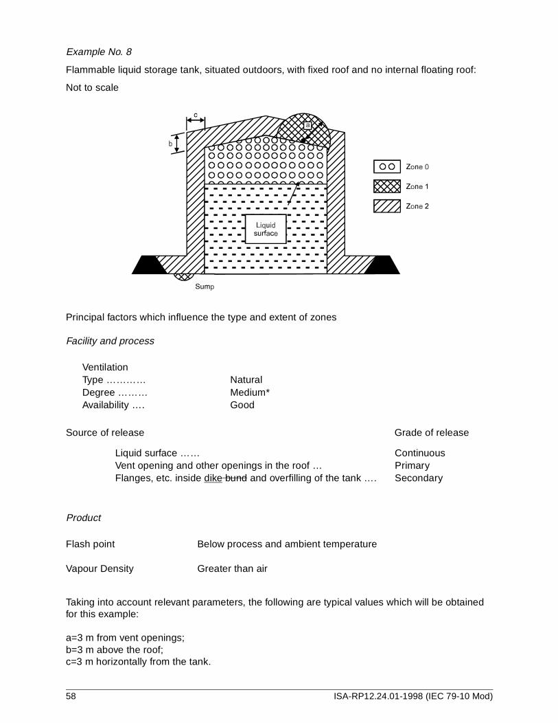
Example No. 8
Flammable liquid storage tank, situated outdoors, with fixed roof and no internal floating roof:
Not to scale
Principal factors which influence the type and extent of zones
Facility and process
VentilationType ………… NaturalDegree ……… Medium*Availability …. Good
Source of release Grade of release
Liquid surface …… ContinuousVent opening and other openings in the roof … PrimaryFlanges, etc. inside dike bund and overfilling of the tank …. Secondary
Product
Flash point Below process and ambient temperature
Vapour Density Greater than air
Taking into account relevant parameters, the following are typical values which will be obtained for this example:
a=3 m from vent openings;b=3 m above the roof;c=3 m horizontally from the tank.
58 ISA-RP12.24.01-1998 (IEC 79-10 Mod)

Example No. 9
Tank car filling installation, situated outdoors, for gasoline, top filling:
Not to scale
Principal factors which influence the type and extent of zones
Facility and process
Ventilation
Type ………… NaturalDegree ……… MediumAvailability …. Poor
Source of release Grade of release
Opening in tank roof …… PrimarySpillage at ground level … Secondary
ProductFlash point Below process and ambient temperatureVapour Density Greater than air
Taking into account relevant parameters, the following are typical values which will be obtained for this example:
a=1.5 m horizontally from source of release;b= horizontally to island (gantry) boundary;c=1.5 m above source of release;d=1 m above ground level;e=4.5 m horizontally from drainage channel;f=1.5 m horizontally from Zone 1;g=1.0 m above Zone 1.
NOTE —If the system is a closed system with vapour recovery, the distances can be reduced, such that Zone 1 may be of negligible extent and Zone 2 significantly reduced.
ISA-RP12.24.01-1998 (IEC 79-10 Mod) 59

Example No. 10
Mixing room in a paint factory:
Not to scale
This example shows one way of using the individual examples Nos. 2 and 5. In this simplified example, four paint-mixing vessels (item 2) are situated in one room. There are also three pumps (item 1) for liquid in the same room.
Principal factors which influence the type and extent of zones are given in the tables in examples Nos. 2 and 5.
Taking into account relevant parameters, (see hazardous area classification data sheets), the following are typical values which will be obtained for this example:
a=2 m;b=4 m; c=3 m;d=1.5 m.
The drawing No. 10 is a plan view, for vertical extent of the zones see examples Nos. 2 and 5.
NOTE—As in examples Nos. 2 and 5, the zones have a cylindrical shape around the sources of release. However, in practice, the zones are usually increased to a box shape if the vessels are situated close to each other. In this way there are no unclassified small pockets.
It is assumed that the pumps and vessels are connected by all-welded pipework and that flanges, valves, etc. are located close to these items of equipment.
In practice, there may be other sources of release in the room, for example open vessels, but these have not been taken into account in this example.
If the room is small, it is recommended that Zone 2 extends to the limits of the room.
60 ISA-RP12.24.01-1998 (IEC 79-10 Mod)

61IS
A-R
P12.24.01-1998 (IE
C 79-10 M
od)
racteristics
P Reference drawing; layout
10 11 12N Ignition
mperature
° C
Group and temperature
class 3)
Any other relevant information and
remarks
260 IIT3
1 e 4.4.1d).23
Hazardous area classification data sheet – Part I: Flammable material flat and chaSheet 1 of 2
lant: paint factory (example 10)
1 2 3 4 5 6 7 8 9o. Name Composition Flashpoint
° C
kg/m3 vol. % Vapour pressure 20
°C kPa
Boiling point
°C
Relative density of gas or vapour to air 2) Te
1 Solvent with low flashpoint
C8H12 -18 0.042 1.2 5.8 81 2.9
) Normally, the value of vapour pressure is given but in the absence of that boiling point can be used (referenc) See 4.4.4.) For example, IIBT3

ISA
-RP
12.24.01-1998 (IE
C 79-10 M
od)
62
se
P Reference drawing: layout
10 11 12 13Hazardous area
N Zone extent m
Vertical Horizontal
Reference Any other relevant information and remarks
1.0* 1.5** Example No. 2
*Above the source of release**From the source of release
1.0* 3.0** Example No. 2
*Above ground level**From the source of release
* * Example No. 5
*Inside vessel
1.0* 2.0** Example No. 5
*Above openings**From openings
1.0* 2.0** Example No. 5
*Above ground level**From the vessel
12345
Hazardous area classification data sheet – Part II: List of sources or releaSheet 2 of 2
lant: paint factory (example 10) Area:
1 2 3 4 5 6 7 8 9. Source of release Flammable material Ventilation
o Description Location Grade ofrelease 1)
Reference 2) Operatingtemperature and
pressure
°C kPa
State 2) Type 4) Degree 5) Availability 6) Zonetype 0-1-2
1 Seal of solvent pump
Pump area
P, S 1 Ambient Ambient L A Medium Fair 1
2 Pool at floor level below solvent pump
Pump area
S 1 Ambient Ambient L A Medium Fair 2
3 Liquid surface on mixing vessel
Mixing area
C 1 Ambient Ambient L A Low Poor 0
4 Opening of mixing vessel
Mixing area
P 1 Ambient Ambient L A Medium Fair 1
5 Spillage of mixing vessel
Mixing area
S 1 Ambient Ambient L A Medium Fair 2
) C - Continuous; S - Secondary; P - Primary.) Quote the number of list in Part 1.) G - Gas; L - Liquid: LG - Liquefied gas; S - solid.) N - Natural; A - Artificial.) See annex B.

Example No. 11
Tank farm for gasoline and oil:
Not to scale
This example shows one way of using the individual examples Nos. 1, 6, 8 and 9. In this simplified example, three storage tanks (bunded) (diked) for gasoline (item 3), five liquid pumps (item 1) placed close to each other, one single pump (item 1), one tank car filling installation (item
ISA-RP12.24.01-1998 (IEC 79-10 Mod) 63

4), two oil tanks (item 5) and one oil/water gravity separator (item 2) are situated within the tank farm.
The principal factors which influence the types of zones are given in examples Nos. 1, 6, 8 and 9.
Taking into account relevant parameters, (see hazardous area classification data sheets), the following are typical values which will be obtained for this example:
a = 3 m;b = 7.5 m;c = 4.5 m;d = 1.5 m
The drawing No. 11 is a plan view; for vertical extent of the zones, see examples Nos. 1, 6, 8, and 9.
For details (zoning inside vessels, zoning extent, zoning around tank vents, etc.) see examples Nos. 1, 6, 8 and 9.
NOTE —It is necessary to use examples Nos. 1, 6, 8 and 9 to obtain the correct zoning of the interior of tanks and separators (Zone 0) together with zoning at tank vents (Zone 1).
In practice there may be other sources of release; however for simplicity, these have not been taken into account.
64 ISA-RP12.24.01-1998 (IEC 79-10 Mod)

65IS
A-R
P12.24.01-1998 (IE
C 79-10 M
od)
racteristics
P Reference drawing; layout
10 11 12N Ignition
emperature°C
Group and temperature
class 3)
Any other relevant information and remarks
280 IIAT3330 IIAT2
>280 IIAT3 The values are estimated
123
Hazardous area classification data sheet – Part I: Flammable material flat and chaSheet 1 of 3
lant: paint factory (example 11)
1 2 3 4 5 6 7 8 9o. Name Composition Flashpoint
° C
kg/m3 vol. % Vapour pressure
20 °C kPa
Boiling point °C
Relative density of gas or vapour to air 2) T
1 Gasoline <0 0.022 0.7 50 <210 >2.52 Fuel oil 55-65 0.043 1 6 200 3.53 Water
containing oil and
gasoline
<0 * >0.7 * * >1.2
) Normally, the value of vapour pressure is given but in the absence of that boiling point can be used (reference 4.4.1d).) See 4.4.4.) For example, IIBT3

ISA
-RP
12.24.01-1998 (IE
C 79-10 M
od)
66
se
P Reference drawing: layout
1 11 12 13ardous area
N extent m
Horizontal
Reference Any other relevant information and remarks
1 3.0* Example No. 1
*Above the source of release**From the source of release
2 * Example No. 2
*Above ground level**From the separator
3.0* Example No. 8
*Above ground level**From separator
7.5* Example No. 8
*Above ground level**From separator
3 * Example No. 8
*Inside the tank
4 3.0** Example No. 8
*3 m around the vent
5 * Example No. 8
*Inside dike bund
6 3.0** Example No. 8
*Above ground level
1)2)3)4)5)
Hazardous area classification data sheet – Part II: List of sources or releaSheet 2 of 3
lant: paint factory (example 11) Area:
2 3 4 5 6 7 8 9 10Source of release Flammable material Ventilation Haz
o. Description Location Grade ofrelease 1)
Reference 2) Operatingtemperature and
pressure
°C kPa
State 2) Type 4) Degree 5) Availability 6) Zone type 0-1-2
Zone
Vertical
Seal of gasoline pump
Pump area
D D Ambient Ambient L A Medium Fair 1 1.0*
Liquid surface on separator
Waste water treatment
C 1 Ambient Ambient L N Low Poor 0 *
N High Poor 1 1.0*
N High Poor 2 3.0*
Liquid surface on gasoline tanks
Tank areas
C 1 Ambient Ambient L N Medium Poor 0 *
Vent opening in gasoline tank
Tank areas
P 1 Ambient Ambient L N Medium Good 1 3.0*
Flanges, etc. inside dike bund of gasoline tanks
Tank areas
S 1 Ambient Ambient L N Medium Fair 2 *
Overfilling of gasoline tanks
Tank areas
SS 1 Ambient Ambient L N Medium Good 2 3.0*
C - Continuous; S - Secondary; P - Primary. Quote the number of list in Part 1. G - Gas; L - Liquid; LG - Liquefied gas; S- solid. N - Natural; A - Artificial See annex B.
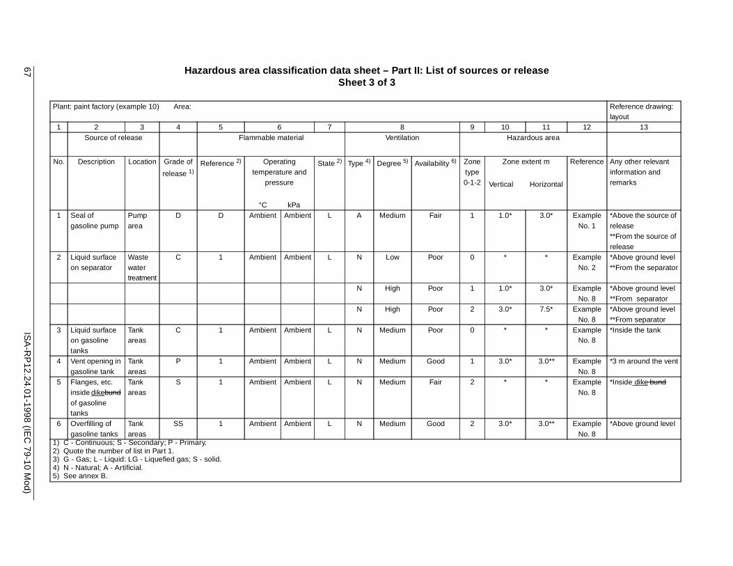
67IS
A-R
P12.24.01-1998 (IE
C 79-10 M
od)
ase
Pl Reference drawing: layout
1 11 12 13azardous area
N ne extent m
l Horizontal
Reference Any other relevant information and remarks
1 * 3.0* Example No. 1
*Above the source of release**From the source of release
2 * Example No. 2
*Above ground level**From the separator
* 3.0* Example No. 8
*Above ground level**From separator
* 7.5* Example No. 8
*Above ground level**From separator
3 * Example No. 8
*Inside the tank
4 * 3.0** Example No. 8
*3 m around the vent
5 * Example No. 8
*Inside dike bund
6 * 3.0** Example No. 8
*Above ground level
1)2)3)4)5)
Hazardous area classification data sheet – Part II: List of sources or releSheet 3 of 3
ant: paint factory (example 10) Area:
2 3 4 5 6 7 8 9 10Source of release Flammable material Ventilation H
o. Description Location Grade of
release 1)Reference 2) Operating
temperature andpressure
°C kPa
State 2) Type 4) Degree 5) Availability 6) Zone type 0-1-2
Zo
Vertica
Seal of gasoline pump
Pump area
D D Ambient Ambient L A Medium Fair 1 1.0
Liquid surface on separator
Waste water treatment
C 1 Ambient Ambient L N Low Poor 0 *
N High Poor 1 1.0
N High Poor 2 3.0
Liquid surface on gasoline tanks
Tank areas
C 1 Ambient Ambient L N Medium Poor 0 *
Vent opening in gasoline tank
Tank areas
P 1 Ambient Ambient L N Medium Good 1 3.0
Flanges, etc. inside dikebund of gasoline tanks
Tank areas
S 1 Ambient Ambient L N Medium Fair 2 *
Overfilling of gasoline tanks
Tank areas
SS 1 Ambient Ambient L N Medium Good 2 3.0
C - Continuous; S - Secondary; P - Primary. Quote the number of list in Part 1. G - Gas; L - Liquid: LG - Liquefied gas; S - solid. N - Natural; A - Artificial. See annex B.

ISA
-RP
12.24.01-1998 (IE
C 79-10 M
od)
68
ntinued)
P Reference drawing: layout
10 11 12 13Hazardous area
N Zone extent m
Vertical Horizontal
Reference Any other relevant information and remarks
1.5* 1.5* Example No. 9
*Above ground level**From release
1.0* 1.5** Example No. 9
*Above ground level**From release
1.0* 4.5* Example No. 9
*Above ground level**From drain channel
* ** *No hazardous area due to the high flashpoint of oil
12345
Hazardous area classification data sheet – Part II: List of sources or release (coSheet 3 of 3
lant: paint factory (example 10) Area:
1 2 3 4 5 6 7 8 9Source of release Flammable material Ventilation
o. Description Location Grade ofrelease 1)
Reference 2) Operatingtemperature and
pressure
°C kPa
State 2) Type 4) Degree 5) Availability 6) Zone type 0-1-2
7 Opening in tank roof of tank car filling installation
Loading area
P 1 Ambient Ambient L A Medium Poor 1
2
8 Spillage at ground inside drainage channel of tank car filling installation
Loading area
S 1 Ambient Ambient L N Medium Poor 2
9 Oil Tank Tank areas
* 2 * * L * * * *
) C - Continuous; S - Secondary; P - Primary.) Quote the number of list in Part 1.) G - Gas; L - Liquid: LG - Liquefied gas; S - solid.) N - Natural; A - Artificial.) See annex B.

69IS
A-R
P12.24.01-1998 (IE
C 79-10 M
od)
nd characteristics
P Reference drawing; layout
10 11 12N Ignition
mperature°C
Group and temperature
class 3)
Any other relevant
information and remarks
1 e 4.4.1d).2
Table C.1 – Hazardous area classification data sheet – Part I: Flammable material flat aSheet 1/1
lant:
1 2 3 4 5 6 7 8 9o. Name Composition Flashpoint
° C
kg/m3 vol. % Vapour pressure
20 °C kPa
Boiling point °C
Relative density of gas or vapour
to air2)Te
) Normally, the value of vapour pressure is given but in the absence of that boiling point can be used (referenc) For example, IIBT3

ISA
-RP
12.24.01-1998 (IE
C 79-10 M
od)
70
r release
P
1 11 12 13zardous area
N e extent m
Horizontal
Reference Any other relevant information and remarks
1)2)3)4)5)
Table C.2 – Hazardous area classification data sheet – Part II: List of sources oSheet 1/1
lant: Area:
2 3 4 5 6 7 8 9 10Source of release Flammable material Ventilation Ha
o. Description Location Grade of release 1)
Reference 2) Operating temperature and
pressure
°C kPa
State 2) Type 4) Degree 5) Availability 6) Zone type 0-1-2
Zon
Vertical
C - Continuous; S - Secondary; P - Primary. Quote the number of list in Part 1. G - Gas; L - Liquid: LG - Liquefied gas; S - solid. N - Natural; A - Artificial. See annex B.

Figure C.1
NOTE—Figure C.1, which appears in IEC 79-10, is not included in ISA-RP12.24.01. Its sche-matic approach to the classification of hazardous areas can lead to a conclusion that deviates from the National Electrical Code (NFPA 70) requirement that there be a Zone 1 “transition zone” between Zone 0 and Zone 2 or unclassified locations, and a Zone 2 “transition zone” between Zone 1 and unclassified locations.
ISA-RP12.24.01-1998 (IEC 79-10 Mod) 71

Figure C.2 – Preferred symbols for hazardous area zones
72 ISA-RP12.24.01-1998 (IEC 79-10 Mod)

Annex D (Informative) – Use of combustible gas detection equipment
The text of Annex D has been added. The underlining has been omitted for clarity.
D.1 Provided the conditions of Par. D.2 are met, the installation of combustible gas detection equipment can be a basis for the following:
a. An inadequately ventilated area containing equipment that could release flammable gas or vapor can be designated as Class I, Zone 2.
NOTE—If an area contains equipment that may release flammable gases or vapors within the area during normal operations, gas detectors are not a feasible alternative unless some degree of ventilation is provided since frequent alarms or equipment shutdowns, or both, are likely to occur.
b. The interior of a building (or similar area) that does not contain a source of flammable gas or vapor can be considered unclassified, even though a door or similar pierced portion or all of the outside of the building is located in a Class I, Zone 2 area, provided the building is of a type construction that is essentially vaportight; that is, the building will not allow the entry of significant quantities of outside atmospheric pressure gas or vapor. Buildings made of fiberglass (molded fiberglass or fiberglass sprayed over wood) or seal welded steel plate normally are used to meet this criteria, but other construction methods may be equally satisfactory. Penetrations should be minimized — normally limited to a personnel entry door(s), electrical cable entries, air conditioning unit(s), and the like. The buildings should contain no windows that can be opened, and the personnel entry door(s) should be provided with adequate gaskets or weather stripping. Openings for air conditioning units and windows should be adequately caulked or otherwise made vaportight. Air conditioning equipment must not introduce outside air into the building. Entries for cables and other services should be made in a vaportight manner.
D.2 The criteria for use of combustible gas detection equipment to meet the objectives of D.1 follow:
a. the gas detectors are of a stationary type, permanently mounted; portable gas detectors will not satisfy this requirement;
b. the gas detection equipment is of a type approved or listed by a nationally recognized testing laboratory (NRTL). It is recommended that equipment meet ANSI/ISA S12.13, Part 1, Performance Requirements, Combustible Gas Detectors;
c. an adequate number of sensors is installed to ensure the sensing of flammable gas or vapor in the building (or similar area) in all areas where such gas might accumulate;
d. sensing a gas concentration of 20 percent LFL (or less) should activate a local alarm (audible or visual, or both, as most appropriate for the location);
e. sensing a gas concentration of 40 percent LFL (maximum) or a gas detector system malfunction should both activate an alarm (audible or visual, or both, as most appropriate for the area) and initiate automatic disconnection of power from all electrical devices in the area that are not suitable for Division 2. The power disconnecting device(s) should be suitable for Class I,
ISA-RP12.24.01-1998 (IEC 79-10 Mod) 73

Division 1, if located inside the building (or similar area); if the disconnecting device(s) is located outside the building (or similar area), it should be suitable for the area in which it is located. Redundant or duplicate components (such as sensors) may be installed to avoid disconnecting electrical power when single component malfunctions are indicated. When automatic shutdown could introduce additional or increased hazard, this technique of area classification reduction should not be used;
NOTE—In the case of sensing 40 percent LFL or a gas detection system malfunction, corrective action to reduce the gas concentration should be initiated immediately.
f. the gas detectors shall be calibrated at a frequency in accordance with the manufacturer’s recommendations, but at least once every three months. Calibration shall be performed by actual exposure of the sensor to a known mixture (nominal 50 percent LFL recommended) of diluent and methane or other gas anticipated in accordance with the manufacturer’s recommendations;
g. user-provided systems bypassing the disconnecting or other “corrective action” devices (but not audible or visual alarm devices) to allow calibration and maintenance are permitted, provided the bypass system is utilized only during calibration or maintenance operations, and only while the area is manned by personnel who are qualified to take corrective action should there be a malfunction in process, storage, transfer, or similar equipment that potentially might release flammable gas or vapor into the area. Any systems in the bypass mode must be made continuously obvious (audibly or visually) to facility personnel; and
h. the building (or similar area) contains no electrically heated parts or components (not enclosed in explosionproof enclosures) that may operate at a temperature equal to or above 80 percent of the ignition temperature (expressed in degrees C) of the gas or vapor involved unless the component has been verified by a nationally recognized testing laboratory (NRTL) to operate below the ignition temperature of the gas or vapor.
NOTE—Electrically heated parts and components could remain at or above the ignition temperature for some time after de-energization.
D.3 It is recommended that gas detectors be installed, operated, and maintained in accordance with ANSI/ISA RP12.13, Part II, Installation Operation and Maintenance of Combustible Gas Detection Instruments.
74 ISA-RP12.24.01-1998 (IEC 79-10 Mod)

Annex E (Informative) – United States major deviations
THE TEXT OF ANNEX E HAS BEEN ADDED.THE UNDERLINING HAS BEEN OMMITTED FOR CLARITY.
General, 1.1 Scope . ISA RP12.24.01 is a recommended practice as opposed to IEC 79-10, which is a standard.
General, 1.2 References . The word “normative” was deleted. The references in ISA RP12.24.01 are both normative and informative. Additional references have been added as required to satisfy United States deviations.
2.4.4 Grouping and Classification . The definitions of Grouping and Classification were replaced by definitions from ANSI/NFPA 70, the (United States) National Electrical Code.
2.4.1-2.4.3 The definitions of Class I, Zones 0, 1, and 2 were replaced by definitions from ANSI/NFPA 70, the (United States) National Electrical Code.
2.20-2.21 The definitions of flammable and combustible liquids from ANSI/NFPA 30, Flammable and Combustible Liquids Code, have been added.
Additional material from API RP 505 was added, addressing matters not covered in IEC 79-10.
Annex C, Notes . Notes were added to explain that the annex is not entirely applicable to installations in the United States since ANSI/NFPA 70 requires a Zone 1 “transition” zone between Zone 0 and Zone 2 locations and a Zone 2 “transition” zone between Zone 1 and non-hazardous locations.
Figure C.1 . Figure C.1 was deleted since it is not compatible with ANSI/NFPA 70 classification methods.
Annex D . Annex D was added as an informative annex to give guidance on the use of combustible gas detectors to reduce area classification in certain cases.
ISA-RP12.24.01-1998 (IEC 79-10 Mod) 75


Developing and promulgating technically sound consensus standards, recommended practices, and technical reports is one of ISA's primary goals. To achieve this goal the Standards and Practices Department relies on the technical expertise and efforts of volunteer commi ttee members, chairmen, and reviewers.
ISA is an American National Standards Institute (ANSI) accredited organization. ISA administers United States Technical Advisory Groups (USTAGs) and provides secretariat support for International Electrotechnical Commission (IEC) and International Organization for Standardization (ISO) committees that develop process measurement and control standards. To obtain additional information on the Society's standards program, please write:
ISAAttn: Standards Department67 Alexander DriveP.O. Box 12277Research Triangle Park, NC 27709
ISBN: 1-55617-649-X
Related Documents