Energies 2022, 15, 947. https://doi.org/10.3390/en15030947 www.mdpi.com/journal/energies Review Recent Research Progress in Piezoelectric Vibration Energy Harvesting Technology Weipeng Zhou, Dongmei Du, Qian Cui, Chang Lu, Yuhao Wang and Qing He* School of Energy Power and Mechanical Engineering, North China Electric Power University, Beijing 102206, China; [email protected] (W.Z.); [email protected] (D.D.); [email protected] (Q.C.); lu‐ [email protected] (C.L.); [email protected] (Y.W.) * Correspondence: [email protected] Abstract: With the development of remote monitoring technology and highly integrated circuit technology, the achievement and usage of self‐powered wireless low‐power electronic components has become a hot research topic nowadays. Harvesting vibration energy from the environment can meet the power consumption requirements of these devices, while it is also of great significance to fully utilize the hidden energy in the environment. The mechanism and three typical working modes of piezoelectric vibration energy harvesting technology are introduced, along with the clas‐ sification of different excitation types of collectors. The progress of research related to piezoelectric vibration energy harvesting technology is reviewed. Finally, challenging problems in the study of piezoelectric energy harvesting technology are summarized, and the future research and develop‐ ment trend of piezoelectric vibration energy harvesting technology is discussed in the light of the current research status of piezoelectric vibration energy harvesting technology. Keywords: piezoelectric vibration; different excitation; research progress; working modes 1. Introduction 1.1. Meaning of Energy Harvesting Low‐power wireless remote monitoring sensors have been widely used with the de‐ velopment of chip technology and highly integrated circuit technology in recent years. These small sensors play an important role in the Internet of Things. Achieving self‐pow‐ ering for these small devices has increased demand for micro‐energy harvesting devices [1–3]. Micro‐energy harvesting is a collection of available energy in the environment, such as wind energy, solar energy, thermal energy, tidal energy, mechanical vibration energy, and even energy in living organisms. These clean energy sources are used to power a variety of low‐power, miniaturized sensor nodes. Traditional small sensors are typically powered by batteries, but the life of chemical batteries is limited and often shorter than that of electronic devices. Sensors are deployed not only in large cities but also in high mountains and remote seas. Periodically replacing the chemical fuel cells that come with the sensors is a difficult and costly maintenance task. Therefore, obtaining energy from the environment to realize self‐powering for these low‐power devices has become a cur‐ rent research hotspot. Self‐powering of small electronic devices can be achieved by obtaining micro‐energy from the environment. This approach can not only replace the traditional batteries that cannot operate for a long time in harsh environments but also ensures that the devices will not be harmed by untimely battery replacement during operation. There are various forms of energy in the environment, and vibration energy is the preferred energy object due to its wide range of existence. Collecting vibration energy for energy supply is con‐ sidered one of the best technical solutions for self‐powering wireless sensor networks. Citation: Zhou, W.; Du, D.; Cui, Q.; Lu, C.; Wang, Y.; He, Q. Recent Research Progress in Piezoelectric Vibration Energy Harvesting Technology. Energies 2022, 15, 947. https://doi.org/10.3390/en15030947 Academic Editor: Philippe Leclère Received: 23 November 2021 Accepted: 24 January 2022 Published: 27 January 2022 Publisher’s Note: MDPI stays neu‐ tral with regard to jurisdictional claims in published maps and institu‐ tional affiliations. Copyright: © 2022 by the authors. Licensee MDPI, Basel, Switzerland. This article is an open access article distributed under the terms and conditions of the Creative Commons Attribution (CC BY) license (https://creativecommons.org/license s/by/4.0/).

Welcome message from author
This document is posted to help you gain knowledge. Please leave a comment to let me know what you think about it! Share it to your friends and learn new things together.
Transcript

Energies 2022, 15, 947. https://doi.org/10.3390/en15030947 www.mdpi.com/journal/energies
Review
Recent Research Progress in Piezoelectric Vibration Energy
Harvesting Technology
Weipeng Zhou, Dongmei Du, Qian Cui, Chang Lu, Yuhao Wang and Qing He*
School of Energy Power and Mechanical Engineering, North China Electric Power University, Beijing 102206,
China; [email protected] (W.Z.); [email protected] (D.D.); [email protected] (Q.C.); lu‐
[email protected] (C.L.); [email protected] (Y.W.)
* Correspondence: [email protected]
Abstract: With the development of remote monitoring technology and highly integrated circuit
technology, the achievement and usage of self‐powered wireless low‐power electronic components
has become a hot research topic nowadays. Harvesting vibration energy from the environment can
meet the power consumption requirements of these devices, while it is also of great significance to
fully utilize the hidden energy in the environment. The mechanism and three typical working
modes of piezoelectric vibration energy harvesting technology are introduced, along with the clas‐
sification of different excitation types of collectors. The progress of research related to piezoelectric
vibration energy harvesting technology is reviewed. Finally, challenging problems in the study of
piezoelectric energy harvesting technology are summarized, and the future research and develop‐
ment trend of piezoelectric vibration energy harvesting technology is discussed in the light of the
current research status of piezoelectric vibration energy harvesting technology.
Keywords: piezoelectric vibration; different excitation; research progress; working modes
1. Introduction
1.1. Meaning of Energy Harvesting
Low‐power wireless remote monitoring sensors have been widely used with the de‐
velopment of chip technology and highly integrated circuit technology in recent years.
These small sensors play an important role in the Internet of Things. Achieving self‐pow‐
ering for these small devices has increased demand for micro‐energy harvesting devices
[1–3]. Micro‐energy harvesting is a collection of available energy in the environment, such
as wind energy, solar energy, thermal energy, tidal energy, mechanical vibration energy,
and even energy in living organisms. These clean energy sources are used to power a
variety of low‐power, miniaturized sensor nodes. Traditional small sensors are typically
powered by batteries, but the life of chemical batteries is limited and often shorter than
that of electronic devices. Sensors are deployed not only in large cities but also in high
mountains and remote seas. Periodically replacing the chemical fuel cells that come with
the sensors is a difficult and costly maintenance task. Therefore, obtaining energy from
the environment to realize self‐powering for these low‐power devices has become a cur‐
rent research hotspot.
Self‐powering of small electronic devices can be achieved by obtaining micro‐energy
from the environment. This approach can not only replace the traditional batteries that
cannot operate for a long time in harsh environments but also ensures that the devices
will not be harmed by untimely battery replacement during operation. There are various
forms of energy in the environment, and vibration energy is the preferred energy object
due to its wide range of existence. Collecting vibration energy for energy supply is con‐
sidered one of the best technical solutions for self‐powering wireless sensor networks.
Citation: Zhou, W.; Du, D.; Cui, Q.;
Lu, C.; Wang, Y.; He, Q. Recent
Research Progress in Piezoelectric
Vibration Energy Harvesting
Technology. Energies 2022, 15, 947.
https://doi.org/10.3390/en15030947
Academic Editor: Philippe Leclère
Received: 23 November 2021
Accepted: 24 January 2022
Published: 27 January 2022
Publisher’s Note: MDPI stays neu‐
tral with regard to jurisdictional
claims in published maps and institu‐
tional affiliations.
Copyright: © 2022 by the authors.
Licensee MDPI, Basel, Switzerland.
This article is an open access article
distributed under the terms and
conditions of the Creative Commons
Attribution (CC BY) license
(https://creativecommons.org/license
s/by/4.0/).

Energies 2022, 15, 947 2 of 34
Currently, many small sensor systems are capable of operating properly with low power
consumption. For example, the power consumption of the temperature sensor system [4]
and the pressure measurement microsystem [5] is only 71 nW and 120 μW, respectively,
for the whole system. In addition, these micro‐systems usually operate at intervals, so
power consumption requirements can be further met with the help of energy storage and
management systems such as supercapacitors to power the sensor nodes.
1.2. Ways of Micro Energy Harvesting
It is a more optimal choice to collect the energy existing in the environment around
the sensor to replace the chemical fuel cell. Currently, the electromechanical conversion
mode can be divided into four modes according to the conversion mechanism, namely,
piezoelectric type [6,7], electrostatic type [8], electromagnetic type [9,10], and triboelectric
type [11,12].
The electromagnet is a closed coil in a magnetic field that cuts magnetic induction
lines, resulting in a change in the magnetic flux and the generation of current in the coil.
Electrostatic energy mainly relies on capacitance. The two conductors and the dielectric
in the middle move relative to each other. As the movement occurs, there is a dielectric
charge between the conductors, which hinders the charge movement and makes the
charge accumulate on the conductors, resulting in the accumulation of charge storage [13].
The working mechanism of the triboelectric generator is the frictional charging effect and
electrostatic effect. When two electrodes are in contact, the two films with different elec‐
tronegativity rub together and carry different charges when they are separated, thus form‐
ing an electric potential difference. At the same time, the back electrodes of the two mate‐
rials are connected by a load. The potential difference makes electrons flow between the
two electrodes to balance the electrostatic potential difference between the films. Piezoe‐
lectricity is caused by the accumulation of charges on the material due to the deformation
of the piezoelectric material to form a voltage difference. Piezoelectric energy harvesting
is the application of the inherent polarization of the piezoelectric material to yield piezo‐
electricity as a simple mechanism of electromechanical conversion. It does not require an
external power source, magnetic field or some other external energy and is very inde‐
pendent.
Piezoelectric vibration energy harvesting (PVEH), as one of the preferred methods,
has the characteristics of a simple structure, easy access to materials, and excellent energy
density and output voltage. At the same time, the structure is easy to miniaturize and easy
to integrate with other devices [14], so it is widely used. Piezoelectric energy harvesters
are capable of producing higher power output than electromagnetic and electrostatic en‐
ergy harvesters [15]. when energy density is considered. In addition, the full coverage of
piezoelectric energy harvesting using low‐profile sensors and the results of various pro‐
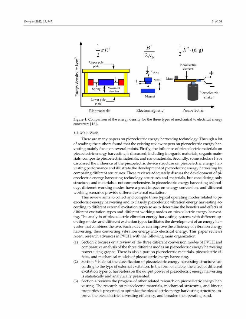
totype energy harvesting devices are reviewed according to Priya et al. [16]. According to
their calculations, the power density of piezoelectric energy harvesting is about three to
five times higher than that of electrostatic and electromagnetic devices, as shown in Figure
1.
Energies 2022, 15, 947 3 of 34
Upper pole plate
Lower pole plate
Spring Movement direction
Magnet
Mass
Fspring
Piezoelectric element
MassE
nerg
y de
nsit
y, m
J/cm
3
Electrostatic Electromagnetic Piezoelectric
21
2E
2
02
B
21
(d g)2
X
Piezoelectric shaker
Figure 1. Comparison of the energy density for the three types of mechanical to electrical energy
converters [16].
1.3. Main Work
There are many papers on piezoelectric energy harvesting technology. Through a lot
of reading, the authors found that the existing review papers on piezoelectric energy har‐
vesting mainly focus on several points. Firstly, the influence of piezoelectric materials on
piezoelectric energy harvesting is discussed, including inorganic materials, organic mate‐
rials, composite piezoelectric materials, and nanomaterials. Secondly, some scholars have
discussed the influence of the piezoelectric device structure on piezoelectric energy har‐
vesting performance and illustrate the development of piezoelectric energy harvesting by
comparing different structures. These reviews adequately discuss the development of pi‐
ezoelectric energy harvesting technology structures and materials, but considering only
structures and materials is not comprehensive. In piezoelectric energy harvesting technol‐
ogy, different working modes have a great impact on energy conversion, and different
working scenarios provide different external excitation.
This review aims to collect and compile three typical operating modes related to pi‐
ezoelectric energy harvesting and to classify piezoelectric vibration energy harvesting ac‐
cording to different external excitation types so as to determine the benefits and effects of
different excitation types and different working modes on piezoelectric energy harvest‐
ing. The analysis of piezoelectric vibration energy harvesting systems with different op‐
erating modes and different excitation types facilitates the development of an energy har‐
vester that combines the two. Such a device can improve the efficiency of vibration energy
harvesting, thus converting vibration energy into electrical energy. This paper reviews
recent research advances in PVEH, with the following main organization.
(1) Section 2 focuses on a review of the three different conversion modes of PVEH and
comparative analysis of the three different modes on piezoelectric energy harvesting
power using graphs. There is also a part on piezoelectric materials, piezoelectric ef‐
fects, and mechanical models of piezoelectric energy harvesting.
(2) Section 3 is about the classification of piezoelectric energy harvesting structures ac‐
cording to the type of external excitation. In the form of a table, the effect of different
excitation types of harvesters on the output power of piezoelectric energy harvesting
is statistically and analytically presented.
(3) Section 4 reviews the progress of other related research on piezoelectric energy har‐
vesting. The research on piezoelectric materials, mechanical structures, and kinetic
properties is presented to optimize the piezoelectric energy harvesting structure, im‐
prove the piezoelectric harvesting efficiency, and broaden the operating band.

Energies 2022, 15, 947 4 of 34
(4) The last section analyzes the problems of the current stage of piezoelectric energy
harvesting technology in the light of the material collected in this paper and proposes
future research directions and work.
2. Mechanism
2.1. Piezoelectric Materials and Piezoelectric Effects
As one of the most important parts of piezoelectric structures, piezoelectric materials
largely influence the performance of the harvesting structures. There are many types of
piezoelectric materials, and different piezoelectric materials have different properties and
are suitable for different applications. We need to choose suitable piezoelectric materials
according to different application fields and application environments, which can be in‐
organic materials, organic or composite materials. The selection of different piezoelectric
materials has a great impact on the performance of the piezoelectric structure.
Inorganic piezoelectric materials usually include piezoelectric single crystals, piezo‐
electric ceramics, and so on. Piezoelectric single crystals, also referred to as piezoelectric
crystals, are usually referred to as quartz crystals. Quartz can produce piezoelectric effects
because the internal structure of the crystals that make it up is not symmetrical. Piezoe‐
lectric single crystals are stable in performance but have a small output power [17]. Piezo‐
electric ceramics, as a class of synthetic electronic ceramic materials that can form a piezo‐
electric effect, have strong piezoelectricity in physical properties, while the strength needs
to be improved. They play an important role in people’s production and life. The most
widely used piezoelectric ceramics are PZT ceramics, which have the advantages of higher
piezoelectric coefficient and better stability [18], but they are not able to withstand exces‐
sive stress and are more prone to brittle fracture [19,20]. Due to the good piezoelectric
properties and stability of PZT ceramics, many piezoelectric energy harvesters use PZT as
a piezoelectric material [21].
Organic piezoelectric materials can also be called piezoelectric polymers. The physi‐
cal properties of organic piezoelectric materials are very different from those of inorganic
piezoelectric materials. Organic piezoelectric materials have a more extensive frequency
range than inorganic piezoelectric materials such as piezoelectric ceramics, are less prone
to fracture, are more sensitive to applied excitation, and are more easily matched to im‐
pedance [22]. In terms of physical properties, organic piezoelectric materials are less
weighty, more flexible, less susceptible to corrosion, and more versatile in shape. They
offer very significant advantages, while being important in several areas especially in
fields that require greater accuracy, such as medicine [23]. However, the polarization
properties of organic piezoelectric materials have not been studied thoroughly and deeply
enough, the sensor sensitivity of the sensitive elements made from them is not high
enough, and the piezoelectric properties of PVDF with different crystalline structures vary
considerably [24]. Therefore, the application of organic piezoelectric materials in daily life
and work has been limited [25].
Piezoelectric composites are formed by combining organic polymers and piezoelec‐
tric materials in an embedded way. The piezoelectric composite is a composite of two
materials, so it has more advantages than the other two single materials. Its high piezoe‐
lectricity and flexibility make it suitable for long‐term use [26]. Its output power is much
greater than that of the piezoelectric ceramic alone at a larger resistance value, indicating
its better piezoelectric performance under certain conditions. However, in general, the pi‐
ezoelectric constants of polymers are usually relatively low [27].
Piezoelectric vibration generators take advantage of the piezoelectric effect of the pi‐
ezoelectric material itself. When certain dielectric crystals are subjected to external me‐
chanical stress, the charges inside the crystal will be relatively displaced to produce po‐
larization, resulting in a bound charge of opposite sign at both ends of the crystal. Accord‐
ing to the different piezoelectric phenomena, the piezoelectric effect is divided into two
kinds: direct piezoelectric effect and inverse piezoelectric effect. The direct piezoelectric

Energies 2022, 15, 947 5 of 34
effect means that the piezoelectric crystal material itself will be deformed, and its surface
deformation will lead to the polarization inside the crystal when the piezoelectric crystal
material is subjected to external mechanical stimulation. The opposite side of the piezoe‐
lectric crystal material collects positive and negative charges. When the mechanical force
from the external environment disappears, the crystal surface of the piezoelectric material
returns to its original uncharged state. On the contrary, the piezoelectric material will de‐
form when an external electric field is applied to the polarization direction of the piezoe‐
lectric material. This phenomenon of mechanical deformation caused by electrical energy
is called the inverse piezoelectric effect ,as shown in Figure 2[28].
Polarizationdirection
Polarizationdirection
E
Figure 2. Schematic diagram of direct piezoelectric effect and inverse piezoelectric effect [28].
There are two ways to extract energy from mechanical vibrational energy. They are
inertial energy, which depends on resistance to mass acceleration, and kinematic energy,
which directly couples the energy collector to the relative motion of different parts of the
energy source [29]. Piezoelectric energy harvesting utilizes inertial energy harvesting.
2.2. Mechanical Model of a Vibration Energy Harvester
Vibration energy harvesting can be divided into three basic types, electrostatic type,
electromagnetic type, and piezoelectric type, depending on the mode of operation. The
operation mode and performance characteristics of each type of generator are very differ‐
ent, and each type has its outstanding performance characteristics. Compared with elec‐
trostatic and electromagnetic energy harvesters, the piezoelectric type has the advantages
of not requiring an external power supply, robust adaptability, and easy miniaturization
[30]. The complete piezoelectric vibration energy harvesters contain two essential parts,
one is the excitation receiving induction device, and the other is the external circuit load.
The core part involved in the excitation receiving induction device is the piezoelectric ma‐
terial, and the piezoelectric vibration energy device uses the piezoelectric material with
piezoelectric effect to realize the conversion of mechanical energy into electrical energy.
A mechanical model using inertial vibration energy was proposed by Williams et al.
[31] as early as 1996. As shown in Figure 3, this model is a single‐degree‐of‐freedom me‐
chanical model consisting of a mass block, a spring, and damping. This model is still active
in micro‐vibration energy harvesting after more than a decade because it is intuitive, sim‐
ple, and effortless to use, and the structure of the model itself is convenient for scholars to
design and research and analyze the interface circuit.
As can be seen in Figure 3, the early mechanical model of vibration energy harvesting
contained a vibrator with a mass of m, a damper with a damping of c, a spring with a
stiffness factor of k, and an energy transducer that converts mechanical energy into elec‐
trical energy within a frame.

Energies 2022, 15, 947 6 of 34
y(t)
z(t)
k c
m
Transducer
Fg
Figure 3. Mechanical model of a vibration energy harvester. Adapted from[32].
Assuming that the frame of the vibration energy harvesting device in Figure 3 is sub‐
jected to a sinusoidal vibration perpendicular to the reference horizontal direction, the
displacement of the frame is
m p 1sin(2π )y t Y f t (1)
where Ym is the vibration amplitude of the frame, mm; fp is the vibration frequency of
excitation, Hz; and 1 is the initial phase. In order to minimize the effect of the “electron damping” introduced by the trans‐
ducer reversal on the vibration source, we assume that the mass of the excited vibration
source is much larger than the m of the oscillator and let the oscillator undergo simple
harmonic forced motion in the vertical direction using inertia. Thus, the relative move‐
ment expression between the vibrator is
m p 2sin 2πz t Z f t (2)
where Zm represents the relative displacement amplitude between the vibrator and the
frame, mm, and 2 is the phase difference between relative displacement z(t) and absolute
displacement y(t).
The generator housing is vibrated with a displacement y(t), the relative motion of the
mass with respect to the housing is z(t), and the differential equation of motion is
( ) ( ) ( ) ( )mz t cz t kz t my t (3)
The force on the mass is equal to the force on the mass‐spring‐damper, that is:
( )F my t (4)
To maximize the output power under certain forms of external excitation, Wu [32]
added a transducer structure to the original model. In addition to structural optimization,
it is also possible to optimize the elasticity coefficient k, the damping coefficient c, the mass
of the oscillator m, and the parameters Fg that match the mode of operation of the trans‐
ducer. First of all, ignoring the effect of the electronic load on the transducer, if
e ( )gF c z t , the mass m subjected to the damping force of the air damping factor ce in the
frame is
e( ) ( ) ( ) ( )y t mz t c c z t kz t (5)

Energies 2022, 15, 947 7 of 34
When the transducer operates in the stable case, the above equation can be trans‐
formed into the s domain after Laplace transformation, and then we have
2 2e( ) ( ) ( ) ( )ms Y s ms Z s c c sZ s kZ s (6)
According to Equation (6), the norm of the relative displacement z(t) can be found as
2
n
22 2
Tn n
( )
1
Y
Z
c
(7)
where ωn is the natural frequency of the harvesters in the case of a short circuit of the
transducer as follows
n
k
m (8)
and cT is indicates the total damping factor as follows
T ec c c (9)
Therefore, the output power P of the transducer can be calculated from Equation (7)
as follows
4
2 2e
2 n2e 22 2
Tn
1 1
2 21
c Y
P F Z c
ck
(10)
From Equation (10), it is clear that when the specific mechanics of the harvesters are
ignored, the output power of the transducer is related to the velocity of the mechanical
relative displacement z, which means that the charge can only be generated when the dis‐
placement occurs. When the external vibration frequency is ωn, the output power of en‐
ergy harvester is
2 2
n en 22 T
m c YP
c
(11)
If the damping introduced by the air is equal to the damping of the mechanical end
itself, that is, ce = c, combined with the relationship 2na Y , the maximum output power
of the vibration energy collector is
2
max
( )
8
maP
c (12)
2.3. Typical Modes
PVEH as a technology mainly uses the mechanical energy–electrical energy conver‐
sion characteristics of piezoelectric materials to achieve energy harvesting. There are var‐
ious operating modes of piezoelectric materials, except for d32, d31, d33, d15, and d24, all
of which have a zero component. Among these five modes, there are the relations: d32 =

Energies 2022, 15, 947 8 of 34
d31 and d24 = d15 [30]. Therefore, the main focus of the research process is on the three
working modes of d31, d33, and d15, as shown in the Figure 4.
Fz
x
y
z z
x
y y
x
FF
Electromechanical conversion mode 33
Electromechanical conversion mode 31
Electromechanical conversion mode 15
Figure 4. Electromechanical conversion type of piezoelectric materials.
2.3.1. Mode d15
In recent years, vibration energy harvesting has been extensively studied to provide
a continuous power source supply for wireless sensors and low‐power electronics. Tor‐
sional shear vibration is widely available in mechanical engineering, and this working
mode can realize high‐efficiency energy conversion. However, it has not yet been well
used in the field of energy harvesting. Some scholars’ research has supplemented the gap
in this regard. Qian et al. [33] proposed a theoretical model of a torsional system consisting
of a shaft and a shear mode piezoelectric transducer and verified the energy harvesting
under different mode couplings by experiments.
It has been shown that the d15 shear mode can achieve higher electromechanical con‐
version efficiency compared to d31 and d33 [34,35]. The sketch of the working mode of
the d15 shear mode is shown in Figure 5.
E P
Figure 5. Shear mode energy harvester.
Ma et al. [36] proposed a composite piezoelectric effect between the vertical surfaces
of a piezoelectric single crystal sheet polarized along the thickness direction and managed
to eliminate the transverse piezoelectric effect along the length direction in the experiment
to obtain the neglected shear piezoelectric effect d15, while the open‐circuit voltage and
power obtained by the superposition of the piezoelectric effect were 1.5 and 3 times the
transverse piezoelectric effect, respectively. Gao et al. [37] proposed energy harvesters of
a bridge shear mode structure. The structure of the harvester they designed is shown in
Figure 6a. Figure 6b is the mechanical analysis model of the structure. The structure uses
a high‐performance relaxed ferroelectric crystal PIN‐PMN‐PT core piezoelectric element
to improve the output performance of the device. The energy harvester achieves a maxi‐
mum power density of 1.378 × 10⁴ W/m3, three times the power density of piezoelectric

Energies 2022, 15, 947 9 of 34
ceramic‐based harvesters of the same structure. With an inertial force of 0.25 N, a voltage
of 21.6 V and a current of 6 × 10⁻⁴ A can be output. Ren et al. [38] designed a piezoelectric
energy harvester based on a PMN‐platinum single crystal with a d15 mode cantilever. The
experiments showed that a peak voltage of 91.23 V could be output and the maximum
power reached 4.16 mW at a cyclic pressure of 0.05 N. Zhou et al. [39] combined the d15‐
mode piezoelectric effect equation with a single‐degree‐of‐freedom model to propose an
energy analysis model for a piezoelectric cantilever beam in shear mode. Experiments
show that the model successfully predicted the electromechanical coupling response of
the piezoelectric cantilever beam. The data from this experimental simulation were also
compared with a piezoelectric cantilever beam [38] with PMN‐platinum single crystals
and brass spacers in shear mode.
x
y
x
(a)
(b)
1mm
0.3m
m
2mm
10mm
Berylium copper
z
Piezoelectric single crystal
F = ma
FNFN
za
Poling direction
FH FH
Figure 6. Working principle of the BSPEH. (a) Schematic of the energy harvester and (b) Mechanical
analysis of the structure [37].
With the deep development of piezoelectric materials, the field of piezoelectric ma‐
terials is moving toward the area of nanomaterials. Nano‐energy harvesting is an expan‐
sion and an important branch of nanotechnology applications in new areas [40,41]. Nano
power technology is a nanogenerator embedded in a material that converts latent mechan‐
ical energy in the environment into electrical energy. Another goal is to achieve self‐pow‐
ered nanoelectromechanical systems, which fits with large‐scale piezoelectric energy har‐
vesting [42]. Majidi et al. [43] introduced a vertically aligned ZnO nanoribbon array struc‐
ture that employs d15 shear mode piezoelectric coupling. In contrast, the nanoribbons
generate electricity through elastic deformation caused by vibration or friction from an
external source. Experiments show that the power density that the device structure can
generate is about 100 nW/mm3, which is relatively low but allows nanotechnology power
generation. Chen et al. [44] proposed a novel actuation design based on the shear defor‐
mation of lead zirconate titanate actuator to deflect the diaphragm and apply the micro‐
fluidic system. Zeng et al. [45] introduced a cantilever beam‐driven low frequency energy
harvester based on the d15 shear mode in order to develop excellent shear mode perfor‐
mance of PMN‐platinum single crystals for low‐frequency applications. As shown in Fig‐
ure 7, the device consists of a cantilever beam and a symmetrically assembled sandwich
structure, and the maximum voltage output and power density of the device at a resonant

Energies 2022, 15, 947 10 of 34
frequency of 43.8 Hz were experimentally verified to be 60.8 V and 10.8 mW/cm3, respec‐
tively. The theoretical and experimental results show that shear‐mode energy harvesters
have great potential for application in wireless sensors. Wang et al. [46] developed a d15
shear‐mode piezoelectric energy harvester capable of harnessing the energy of pressur‐
ized water streams. Experimental results show that when the harvester receives an ampli‐
tude of 20.8 KPa and a frequency of 45 Hz from the outside world, the output open‐circuit
voltage and instantaneous output powers are 72 mV and 0.45 nW, respectively. These
studies provide an excellent perspective for energy harvesting using d15 shear‐mode pi‐
ezoelectric coupling.
(a)
(b) (c)
PMNT
Hp Hb
tp
tp
Base
Frame
Vout
Copper Block
P Cantilever
Proof mass
Vout
P
P
P
Lc
T1
3
31
K C
Meq
Z(t)
y(t)
Figure 7. (a) Schematic and (b) SDOF model of the proposed S‐CANDLE device. The arrows in the
PMNT wafers indicate the poling direction. (c) Force analysis of the middle copper block and one
PMN‐PT wafer. Adapted from [45].
2.3.2. Mode d33
It is known that among the operating modes of piezoelectric materials, d15 achieves
the highest performance output, but the difficulty in achieving the d15 mode is often the
greatest. The d33 mode is approximately twice as high as the d31 mode, so the harvester
in the d33 operating mode is expected to achieve higher performance [47].
Choi et al. [48] developed an energy harvesting MEMS device based on thin‐film lead
zirconate titanate (PZT). It uses a dual piezoelectric wafer structure, and the PZT film is
made into a cross shape. The experiment investigated PEH with IDE by analyzing the
effect of verifying the mass, beam shape, and damping on the output power, but neglected
that the configuration parameters of the electrodes may affect the device performance.
Park et al. [49] introduced a microelectromechanical system energy harvester using the
d33 piezoelectric mode, as shown in Figure 8. This experiment simulated and analyzed

Energies 2022, 15, 947 11 of 34
the voltage and impedance of the d33 mode piezoelectric energy harvesting while obtain‐
ing a peak voltage of 4.4 V and a power output of 1.1 μW at 0.39 g acceleration and vibra‐tion 528 Hz frequency. However, they did not verify the effect of the change in electrode
size on the output power.
Figure 8. Schematic drawing of the proposed piezoelectric MEMS energy harvester operating in the
d33 mode for the purpose of scavenging low vibrations [49].
Although the performance of energy harvesting devices in the d33 mode can be op‐
timized by changing the electrode size, the effect of electrode size variation on the output
power has not been studied. To solve this problem, Kim et al. [50] investigated a microe‐
lectromechanical system energy harvesting device based on a single piezoelectric wafer
cantilever structure consisting of forked finger‐shaped electrodes in the d33 mode. In this
study, the output power was modeled using angle‐preserving mapping and Roundy’s
sequential circuit model, and the new analytical equation of power output well explained
the effect of electrode size on the output power of d33 mode. Shen et al. [51] introduced a
piezoelectric thin‐film energy harvester based on the d33 mode of helical electrodes,
which uses double‐sided helical electrodes to achieve in‐plane piezoelectric film polariza‐
tion. Although the d33 mode had better device performance, the efficiency of energy har‐
vesting at low frequencies was still not high enough. To improve the energy harvesting
efficiency at low frequencies, Sun et al. [52] derived the output equations for voltage and
power for series and parallel piezoelectric stacks in the d33 mode based on the piezoelec‐
tric equations and equivalent circuits to improve the energy harvesting efficiency at low
frequencies. It is clear that if you want to get a higher voltage, you should choose a piezo‐
electric stack series in the experiment. Similarly, you can use parallel connection if you are
going to get higher power. Kashyap et al. [53] proposed an analytical model for the distri‐
bution parameters of the d33 mode collector. Although they investigated the electrome‐
chanical coupling, the neighboring mode effects of the single‐mode approximation were
not considered in their study, and the experimental results overestimated the load re‐
sistance value. Ahmad et al. [54] applied the piezoelectric d33 mode to a piezoelectric mi‐
cromechanical ultrasound transducer, which improved the operating sensitivity, but the
expansion of bandwidth was not desirable.
Although the d33 mode is better than the d15 and d31 modes in terms of perfor‐
mance, there are still some difficulties in obtaining higher output performance only in the
structure because it is difficult to improve the coupling and electromechanical coefficients
in the structure. To address the corresponding problem, Tang et al. [55] prepared PMN‐

Energies 2022, 15, 947 12 of 34
platinum piezoelectric thick films using a hybrid process of wafer bonding and mechani‐
cal grinding for thinning and developed a d33‐mode harvester based on interdigital elec‐
trodes to address the related problem. Experiments show that the harvester obtained a
peak voltage of 5.36 V, a power of 7.182 μW, and a power density of 0.018 mW/cm3 at a
vibration level of 1.5 g acceleration and an operating condition of 406 Hz. Sil et al. [56] set
several different parameters to analyze the performance of the model to optimize the vi‐
bration energy harvesting performance in d33 mode, and an output voltage of 200 mW
was obtained when 1 N force was applied to the model. Wu et al. [57] introduced a barbell‐
type piezoelectric energy harvester in d33 mode using BiScO3‐PbTiO3 high‐temperature
piezoelectric ceramics for the need of vibration energy harvesting in high‐temperature
environments. The experiment set the energy harvester to operate at 1 g acceleration at 25
°C to obtain a power output of 4.76 μW and to double the power output at high tempera‐
tures of 150–250 °C. Compared with the d31 model, the experimental model is well
adapted to high temperature conditions and exhibits good piezoelectric effects, which
provides a good demonstration of a piezoelectric energy harvester working for wireless
sensors in high‐temperature environments. Liu et al. [58] investigated a two d33‐mode
rectangular multilayer single‐crystal stack applying Pb(In1/2Nb1/2)O3‐Pb(Mg1/3Nb2/3)O3‐
PbTiO3 material to improve the high power output of barbell‐type energy harvesters. The
study compared the different output power in series and parallel with a multilayer large
piezoelectric element. The experiment shows that the maximum power density that can
be generated by the wafer stack in series is 39.7 mW/cm3 under the working condition of
5 g acceleration from the outside, with a maximum output current of 800 μA in parallel
circuits. This also verifies that the model has strong vibration durability.
Although the ability to use piezoelectric stacks in d33 mode for mechanical‐to‐elec‐
trical energy conversion has improved, most studies are mainly based on simplified sin‐
gle‐degree‐of‐freedom (SDOF) models or transfer matrix models. Qian et al. [59] con‐
structed a distributed parameter electromechanical model of a multilayer piezoelectric
stack harvester by applying the axial vibration theory of elastic rods. This electromechan‐
ical device introduces a first‐order numerical model to verify the performance of the de‐
vice in terms of voltage, current, and power output under different types of external excitation.
2.3.3. Mode d31
Although the piezoelectric d33 mode conversion can achieve higher voltage output,
particularly for low‐pressure sources and occasions where the size is limited, and the elec‐
trode configuration is simplified, the advantages of d33 over d31 are not so obvious. The
d31 mode has greater advantages, especially in microelectromechanical system applica‐
tions [60]. Therefore, the most commonly used piezoelectric harvester is the d31 mode,
and the normal strain is perpendicular to the electric field direction. This is because under
such conditions, the piezoelectric material can operate in pure bending mode at low cost.
The sketch of the operating mechanism of the d31 mode is shown in Figure 9.

Energies 2022, 15, 947 13 of 34
EP
EP
Figure 9. Transverse mode energy harvester.
In 2006, Fang et al. [61] developed a harvester with a different structure from the
conventional cantilever beam, double support beam, and diaphragm. This harvester was
designed based on a composite micro‐cantilever beam with an optional verified nickel
mass in d31 mode. The structure has a metal block at the free end, which reduces the
natural frequency of the structure. It is more sensitive to a low‐frequency environment,
and the voltage output of 0.89 V was obtained at a resonant frequency of 608 Hz. With
further development of the research, some scholars found that the root of the cantilever
beam is often easy to be ignored in the design of the strength, resulting in the structure of
the whole device that does not adapt to the more complex working conditions. Wang et
al. [62] fabricated and tested a micro‐piezoelectric energy harvester of the two‐vibrator
double‐cantilever‐sorghum type, which also used a curve‐widening method for the root
for structural optimization. The structure was able to obtain a power output of 2.347 μW
at 40.2 Hz and 0.25 g acceleration but also exhibited good stiffness, resulting in the insen‐
sitivity of the device to the subharmonic frequency response. Structural breakthroughs
can provide an effective way to achieve increased power output. Zhang et al. [63] de‐
signed a novel flexible amplification mechanism to achieve larger energy output, which
was designed using a pseudo‐rigid body and topology optimization approach to integrate
a piezoelectric stack into an energy harvesting pedal in the d31 mode.
Since the d31 mode has some shortcomings, it is challenging to achieve high power
output purely from the structure. Therefore, optimizing the piezoelectric power output
by changing the piezoelectric material becomes another area for research. Yang et al. [64]
prepared a high‐performance piezoelectric ceramic film using the thinning technique and
PZT‐bonding technique to establish a parametric model of the energy harvester. The ex‐
perimental results show that the maximum output voltages that the harvester could ob‐
tain under 0.5 g and 1.0 g acceleration were 3.4 V and 6.08 V, and the corresponding output
powers were 20.2 μW and 57.6 μW. The experiment demonstrates that the energy conver‐
sion efficiency of the harvester varies at different accelerations, and the energy conversion
efficiency at 0.5 g acceleration is higher than that at 1 g acceleration, which is 38.15%. Guan
et al. [65] proposed a composite cantilever beam structure based on the d31 mode in order
to solve the problem of collecting the frequency range, and this study explored the d31
and d33 mode coupling. Banerjrr et al. [66] developed a fully coupled electromechanical
Timoshenko model, and the theory can be well applied to transverse mode energy har‐
vesters. Singh et al. [67] introduced a piezoelectric vibration energy harvester based on
the d31 mode, sandwiching a zinc oxide piezoelectric layer between two metal electrodes.
When studying the resonant frequency, it was found that the natural frequency of the

Energies 2022, 15, 947 14 of 34
device was 235.38 Hz and the device was able to obtain an open circuit voltage of 306 mV
at 0.1 g harmonic acceleration.
Table 1 lists the characteristics of several typical piezoelectric operating mechanisms.
A simple comparison shows that the working mechanism of the d15 shear mode has a
relatively large advantage in power output and power density in general among the three
typical operating mechanisms. There are relatively few research papers on the d15 shear
mode because it is difficult to obtain the force of the shear mode in a vibrating source,
notwithstanding that the d15 shear mode is excellent in terms of power output and power
density. Although these reports show that the output power of the d33 mode at low ac‐
celeration is in the microwatt range, considering that the size and volume of the entire
piezoelectric material in laboratory tests are relatively small, the output power is also con‐
siderable. The d31 mode has great challenges in terms of high‐power output but has ex‐
cellent performance in the low‐frequency field, which lays the foundation for the d31
mode to exhibit excellent performance in micro‐electromechanical systems.
Table 1. Comparison of the characteristics of several typical piezoelectric operating mechanisms.
Ref. Modes Materials Voltage (V) Power (mW) Acceleration (g) Density
(mW/cm3)
Gao et al. [37] d15 PIN‐PMN‐PT 21.6 12.96 3.0 13.78
Zeng et al. [45] d15 PMN‐PT 60.8 0.78 1.0 10.8
Ren et al. [38] d15 PMN‐PT 91.23 4.16 1.0 4.48
Park et al. [49] d33 PZT 4.4 0.001 0.39 7.3
Tang et al. [55] d33 PMN‐PT 5.36 0.0078 1.5 0.018
Wu et al. [57] d33 BS‐PT 8.45 0.0047 1.0 ~
Wang et al. [68] d33 PZT‐5 37.6 10.036 1.0 0.0743
Wang et al. [62] d31 PZT 4.9 0.003 0.25 ~
Yang et al. [64] d31 PZT 6.08 0.058 1.0 5.14
Palosaari et al. [69] d31 Soft ceramic 7.0 0.66 1.0 1.37
Wu et al. [70] d31 BS‐PT ceramic 12.0 0.013 1.0 0.04
3. Energy Harvesters of Different Excitation Types
Since the first appearance of energy harvesters in 1990, many scholars have proposed
many principles, mechanisms, and implementation methods [42,71], especially in piezoe‐
lectric vibration energy harvesting structures (PVEHS), with numerous innovations.
Therefore, many high‐efficiency, wide‐band, innovative piezoelectric vibration energy
harvesting structures have emerged, which to a large extent have made piezoelectric en‐
ergy harvesters widely studied and popularized.
Piezoelectric vibration energy harvesters are typical composite structures, which are
composed of a piezoelectric structure and a vibrational conversion structure, including
AC–DC conversion circuits, energy storage part, and so on [72,73]. As shown in Figure 10,
the conventional piezoelectric vibration energy harvesters are covered with one or two
layers of piezoelectric material on both sides of the cantilever beams, i.e., single and dou‐
ble piezoelectric wafer piezoelectric energy harvesting structures. They are usually at‐
tached to the main structure, equipped with a mass block at the top of the cantilever, and
tuned to the resonant frequency within the range available to the environment. The pie‐
zoelectric element is excited in the desired vibration mode under a vibration conversion
mechanism when subjected to forced vibration, and then a voltage output is generated by
the direct piezoelectric effect of the piezoelectric material [74]. Most piezoelectric trans‐
ducers operate in a resonant state in order to obtain the maximum power output. It is the
optimal state when the fundamental frequency of the environment is compatible with the
frequency of the piezoelectric transducer [75].

Energies 2022, 15, 947 15 of 34
Base Excitation
Piezoelectric Elements
Base Structure
+
-
Iout
VoutRl
HostStructure
Figure 10. Schematic diagram of a typical PVEH. The bimorph structure of the PVEH is only for
demonstration [72].
3.1. Impact‐Type Harvesters
Piezoelectric vibration energy harvesting structures can be significantly divided into
two types; impact type and resonant type. The impact‐type harvester operates without
concern about resonant frequency and is used in impact excitation environments. Reso‐
nant energy harvesting structures must operate at resonant frequencies and achieve max‐
imum power output while obtaining maximum displacement [76].
Chen et al. [76] designed an impact‐driven piezoelectric energy harvester (PEH) in a
magnetic field, which is based on the energy principle to establish a MDOF (multi‐degree
of freedom) mathematical model to calculate the displacement, velocity, and voltage out‐
put of PEH. The results of the study showed that the energy that can be generated by a
single impact is 0.405 mJ. Chen et al. [77] reported a hybrid vibration energy harvester
with a generator that induces vibration operation in shock mode, which triggers vibration
operation in shock mode, and with an electromagnetic induction component attached to
the top of the cantilever beam. The electrical energy collected by the two impacted piezo‐
electric plates was 429.3 μW at an amplitude of 4.5 mm and a frequency of 13 Hz, which
showed that the piezoelectric elements operating in the impact‐induced vibration mode
could have greater power output than their counterparts in the impact mode. Mahmoud
[78] studied the collection of vibrational energy from a freely falling droplet at the top of
a lead zirconate titanate piezoelectric cantilever beam, where the kinetic energy of the
droplet was converted into mechanical stress during droplet impact, forcing the piezoe‐
lectric structure to vibrate and generate an electrical charge. The experimental results
show that 0.23 g of water droplets falling at a speed of 3.43 m/s can generate 23 μW en‐
ergy. Ilyas et al. [79] studied a device that harvests the energy of raindrop impact using
piezoelectric materials. It was shown that the energy output of the device was less than 90
nW and the average power of a single device was not high, but this study also provides a
good perspective for the study of impact piezoelectric energy. In addition, Liu et al. [80]
designed a piezoelectric energy harvester consisting of silicon beams and mass blocks
made of silicon to achieve a broadband, low‐resonance energy harvesting. It can output a
stable power generation from 19.4 nW to 51.3 nW in the operating frequency range of 30
Hz to 47 Hz under the impact of 1 g acceleration. Gu et al. [81] introduced a method of
impinging a low‐frequency resonator on a high‐frequency resonator so that energy is col‐
lected mainly at the coupled vibration frequency of the system. The experimental results
show that the coupled vibration method improved the efficiency of electrical energy trans‐
fer, and the average power output was 0.43 mW at 8.2 Hz and 0.4 g acceleration, corre‐
sponding to 25.5 μW/cm3.
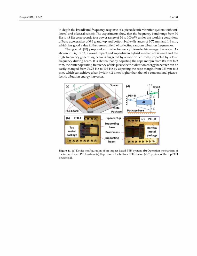
Liu et al. [82] reported a broadband harvester introduced by a mechanical brake in
order to enable a wide range of operating bands, as shown in Figure 11. They investigated
Energies 2022, 15, 947 16 of 34
in depth the broadband frequency response of a piezoelectric vibration system with uni‐
lateral and bilateral cutoffs. The experiments show that the frequency band range from 30
Hz to 48 Hz corresponds to a power range of 34 to 100 nW under the working conditions
of base acceleration of 0.6 g and top and bottom brake distances of 0.75 mm and 1.1 mm,
which has good value in the research field of collecting random vibration frequencies.
Zhang et al. [83] proposed a tunable frequency piezoelectric energy harvester. As
shown in Figure 12, a novel impact and rope‐driven hybrid mechanism is used and the
high‐frequency generating beam is triggered by a rope or is directly impacted by a low‐
frequency driving beam. It is shown that by adjusting the rope margin from 0.5 mm to 2
mm, the center operating frequency of this piezoelectric vibration energy harvester can be
easily changed from 74.75 Hz to 106 Hz by adjusting the rope margin from 0.5 mm to 2
mm, which can achieve a bandwidth 4.2 times higher than that of a conventional piezoe‐
lectric vibration energy harvester.
Figure 11. (a) Device configuration of an impact‐based PEH system. (b) Operation mechanism of
the impact‐based PEH system. (c) Top view of the bottom PEH device. (d) Top view of the top PEH
device [82].

Energies 2022, 15, 947 17 of 34
Phase 1 Phase 4
Phase 2
(a)
(b)
L0
Piezoelectric LayerHFGB
Rope: L
LFDB
Proof mass
Gap: d1
Phase 3
Figure 12. Architecture (a) and operation mechanism (b) of the proposed PVEH system [83].
Yin et al. [84] proposed a dual‐impact drive FUC‐PEH system consisting of two pie‐
zoelectric energy harvester units, as shown in Figure 13. Based on the single‐degree‐of‐
freedom system and the piezoelectric coupling factor, the corresponding model was es‐
tablished. Theoretical calculations and experimental tests show that the energy harvester
can achieve high power output in the frequency range of operating band from 3.5 Hz to
15 Hz under different accelerations. The average output power is 1.17 mW at an accelera‐
tion of 6 m/s2 and a frequency of 9.8 Hz, while the average output power can reach 1.86
mW at an excitation frequency of 15 Hz.
Figure 13. Geometry of the proposed energy harvester.
Since the human body is accompanied by vibrational energy in motion, the realiza‐
tion of self‐powered wearable devices has also become a hot topic nowadays. Therefore,
impact energy harvesters have a wide range of applications in this field as well. Halim et
al. [85] proposed and demonstrated an impact‐based frequency up‐converted wide band‐

Energies 2022, 15, 947 18 of 34
width piezoelectric energy harvester. The device is designed to impact two high‐fre‐
quency piezoelectric generating beams with a low‐frequency driving beam having a hor‐
izontally extended tip mass, and after the impact, the beam stiffness during the coupled
vibration is used to broaden the bandwidth of the collected frequencies. Experiments
show that a peak power of 377 μW can be generated at 0.6 g acceleration and 14.5 Hz
operation, which corresponds to a power density of 58.8 μW/cm3. Figure 14 shows the
schematic structure and the theoretical linear model of the device.
md d
kg1 cg1
kg2
cg2
cd
kd
kg1 = kg2 = kg
cg1 = cg2 = cg
Figure 14. SDOF piecewise linear model [85].
Vijayan et al. [86] investigated nonlinear energy harvesting in coupled collisional sor‐
ghums. They found that using shocks for energy harvesting is an effective means to in‐
crease the operating bandwidth of energy harvesters. Compared to a linear system that
excites only one mode, a nonlinear shock can excite multiple modes for the same excitation
frequency. In addition, piezoelectric ceramics, as materials with excellent piezoelectric
properties, have been applied to shock‐type vibration energy harvesting. Most scholars at
the beginning focused their research around the first resonance of ceramics but neglected
the energy that can be brought by the second resonance. Halim et al. [87] proposed a
broadband low‐frequency vibration energy harvester based on piezoelectric ceramics,
which used mechanical shocks to transmit secondary forces to a ceramic cantilever sec‐
ondary sorghum, leading to an increase in strain while exciting a nonlinear frequency
conversion mechanism, which directly increases the power and operating bandwidth of
the output. The study shows that it can output 449 μW peak power at a mass ratio of 5.8
and a braking distance of 0.5 mm and 17 Hz, and the device can collect frequencies in the
range of 9 Hz to 24 Hz at 1 g acceleration. Isarakorn et al. [88] introduced a two‐stage
energy harvesting device for generating electricity from human footsteps using the prin‐
ciple of frequency up‐conversion in the form of a stamped cantilever beam. It was able to
output 0.82 mW of average power in an operating environment with a frequency reso‐
nance of 14.08 Hz and a 0.93 g acceleration.
3.2. Resonant‐Type Harvesters
Resonant energy harvesting structures are known to have special requirements for
excitation from the environment. Unlike impact operation, resonant energy harvesters
need to consider the ambient excitation frequency versus the natural frequency of the har‐
vesting structure itself. The natural frequency of the cantilever structure is essential be‐
cause the resonant frequency of the piezoelectric cantilever beam must be tuned to match
the harmonic frequency of the vibration source to obtain the maximum power value.

Energies 2022, 15, 947 19 of 34
Naim et al. [89] investigated the mechanical and electrical properties of a mechanically
vibrating piezoelectric cantilever beam. The study showed that the voltage and power
collected at 1 g acceleration and 345.75 Hz were 595.5 mV and 14.85 μW, respectively.
Different researchers have tried to make a breakthrough in cantilever beam types of en‐
ergy harvesting [90,91]. Erturk et al. [92] proposed a model of a double piezoelectric wafer
cantilever beam with a tip mass attachment and derived an analytical solution for the bi‐
morph cantilever structure. Magoteaux et al. [93] used two different types of energy har‐
vesting regarding UAV landing gear. They used a cantilever beam and a curved beam
with a piezoelectric material, and their experiments showed that the curved beam pro‐
duced more energy than the simple cantilever beam. Erturk et al. [94] proposed a distrib‐
uted parameter model for analyzing the electromechanical coupling behavior of L‐shaped
piezoelectric energy harvesters. It was shown that the L‐shaped structure can be tuned to
have two closer natural frequencies than a conventional cantilever beam, and that the L‐
shaped sorghum had a higher output power than the cantilever beam.
The performance of vibrating energy harvesters is well related to the structure, so
many scholars have tried to innovate the structure to optimize each device’s performance.
Liu et al. [95] fabricated a power generator array based on thick‐film piezoelectric cantile‐
ver beams using microelectromechanical technology. The key of the structure is to in‐
crease the flexibility of the collection frequency and expand the excitation band by array‐
ing piezoelectric cantilever beams. The effective power of this prototype is 3.98 mW, while
a small range of frequency modulation can be achieved. Most resonant energy harvesting
devices are passive. Luo et al. [96] explored an active energy harvesting technology that
used a piezoelectric–mechanical‐coupled spring‐mass‐damped mechanical resonator and
developed a mathematical model of the piezoelectric dynamical system. This study theo‐
retically demonstrated that the power harvested by the device could be the maximum of
all excitation frequencies. In other words, at resonant frequencies, active technology has a
unique advantage over other technologies on a technical level. Active dynamic energy
harvesting technology is well promoted because it can be used to broaden the bandwidth
of piezoelectric resonant energy harvesting systems. Stein et al. [97] introduced a new res‐
onant inverter topology that enables dynamic energy harvesting. The experiment demon‐
strated that the output power of this structure was 7.7 times the conventional under non‐
resonant operating conditions. It performed even better near the resonant frequency, with
two times the power of the traditional output.
We know that energy harvesters using resonant‐type mechanisms generally face two
major challenges: first, the output power that resonant structures can produce in low‐fre‐
quency vibration environments is low and cannot meet the demand; second, vibration
structures are effective in collecting frequencies in a small range near the resonant fre‐
quency, but they cannot achieve a wide range of resonant frequency collection. Dhakar et
al. [98] designed a novel low‐power piezoelectric energy harvester, as shown in Figure 15.
It consists of a composite cantilever beam and a proof mass at the free end. To reduce the
natural frequency of the structure, the composite cantilever beam design was used to re‐
duce the resonant frequency to 36 Hz. The composite cantilever beam consists of a piezo‐
electric bimorph and a polymer beam (soft spring) mechanically connected along the lon‐
gitudinal direction. Li et al. [99] designed a dual resonant structure for a piezoelectric
PVDF thin‐film energy harvester, and the adopted dual cantilever beam structure
achieved resonance collection at 15 Hz and 22 Hz. A broadening of the frequency band
was achieved when the cantilever beam collided due to the large amplitude to produce
violent mechanical coupling, and vibration frequencies from 14 Hz to 28 Hz were collected
at 1 g acceleration. Moreover, this dual resonance structure of the device obtained higher
power than the sum of two independent devices in the low‐frequency environment.

Energies 2022, 15, 947 20 of 34
Piezoelectric bimorph Clamping setup
Proof mass
Polymer beam
l1l2
W1 W2
Figure 15. Design of PEH‐S with a polymer spring attached to piezoelectric bimorph [98].
The ability of a piezoelectric device to acquire vibration energy depends on the ge‐
ometry of the cantilever beam to some extent. Hosseini et al. [100] used the Rayleigh–Ritz
method to design a computational trapezoidal V‐shaped cantilever beam and obtained an
exact analytical formula based on the resonant frequency, as shown in Figure 16. The for‐
mula presents a novel idea that the simplest triangular tapered cantilever yields the larg‐
est resonant frequency and the highest sensitivity among all trapezoidal V‐cantilevers of
uniform thickness, and the sensitivity decreases by increasing the ratio of the trapezoidal
bases. Huang et al. [101] proposed a multi‐degree‐of‐freedom broadband vibration energy
harvesting mechanism based on a frequency interval‐shortening mechanism to achieve
broadband vibration energy harvesting. The experiment was performed with five end‐
mass, symmetrically distributed U‐shaped cantilever beams and a straight beam together,
and the output power was experimentally obtained at several different frequencies. The
experimental results showed that five voltage peaks occurred within an operating fre‐
quency of 10 to 30 Hz. At the same time, the structure exhibited superior performance
over the asymmetric M‐shaped cantilever beam and also achieved a broader frequency
band collection.
Figure 16. Division of a trapezoidal cantilever beam into some V‐shaped beams [100].
Shi et al. [102] also examined broadband piezoelectric vibration energy harvesting.
They proposed a structure that consisted of a movable mass block attached to a piezoelec‐
tric cantilever beam. It can actively adjust the resonant frequency to match the ambient
vibration excitation frequency. This structure uses a micro stepper to adjust the position
of the mass block to achieve an adjustable resonant frequency. Experiments showed that
the structure reached a maximum extraction efficiency of 84.8% and a frequency spread‐
ing rate of 60.56%. Such results provide an excellent example for future broadband har‐
vesting of wide‐band collectors.
Table 2 shows the performance of some existing piezoelectric energy harvesting
mechanisms. We can see that piezoelectric energy harvesting structures are roughly clas‐
sified into two categories in terms of classification. One is the impact‐type piezoelectric
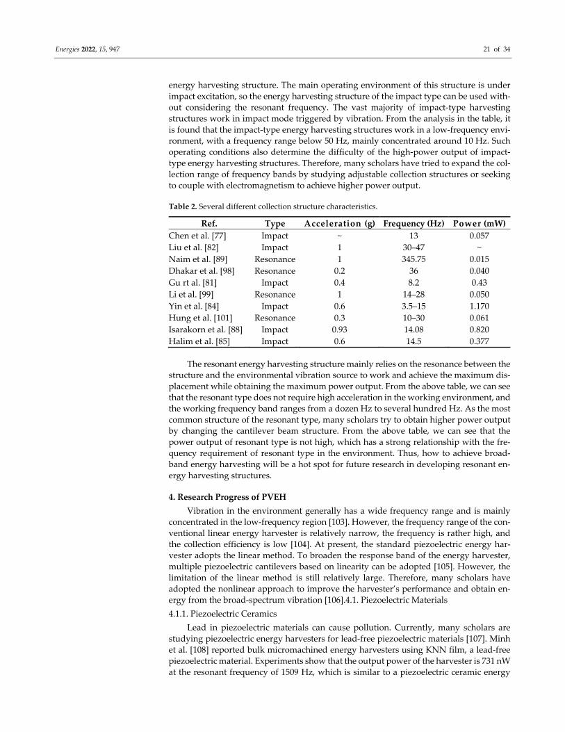
Energies 2022, 15, 947 21 of 34
energy harvesting structure. The main operating environment of this structure is under
impact excitation, so the energy harvesting structure of the impact type can be used with‐
out considering the resonant frequency. The vast majority of impact‐type harvesting
structures work in impact mode triggered by vibration. From the analysis in the table, it
is found that the impact‐type energy harvesting structures work in a low‐frequency envi‐
ronment, with a frequency range below 50 Hz, mainly concentrated around 10 Hz. Such
operating conditions also determine the difficulty of the high‐power output of impact‐
type energy harvesting structures. Therefore, many scholars have tried to expand the col‐
lection range of frequency bands by studying adjustable collection structures or seeking
to couple with electromagnetism to achieve higher power output.
Table 2. Several different collection structure characteristics.
Ref. Type Acceleration (g) Frequency (Hz) Power (mW)
Chen et al. [77] Impact ~ 13 0.057
Liu et al. [82] Impact 1 30–47 ~
Naim et al. [89] Resonance 1 345.75 0.015
Dhakar et al. [98] Resonance 0.2 36 0.040
Gu rt al. [81] Impact 0.4 8.2 0.43
Li et al. [99] Resonance 1 14–28 0.050
Yin et al. [84] Impact 0.6 3.5–15 1.170
Hung et al. [101] Resonance 0.3 10–30 0.061
Isarakorn et al. [88] Impact 0.93 14.08 0.820
Halim et al. [85] Impact 0.6 14.5 0.377
The resonant energy harvesting structure mainly relies on the resonance between the
structure and the environmental vibration source to work and achieve the maximum dis‐
placement while obtaining the maximum power output. From the above table, we can see
that the resonant type does not require high acceleration in the working environment, and
the working frequency band ranges from a dozen Hz to several hundred Hz. As the most
common structure of the resonant type, many scholars try to obtain higher power output
by changing the cantilever beam structure. From the above table, we can see that the
power output of resonant type is not high, which has a strong relationship with the fre‐
quency requirement of resonant type in the environment. Thus, how to achieve broad‐
band energy harvesting will be a hot spot for future research in developing resonant en‐
ergy harvesting structures.
4. Research Progress of PVEH
Vibration in the environment generally has a wide frequency range and is mainly
concentrated in the low‐frequency region [103]. However, the frequency range of the con‐
ventional linear energy harvester is relatively narrow, the frequency is rather high, and
the collection efficiency is low [104]. At present, the standard piezoelectric energy har‐
vester adopts the linear method. To broaden the response band of the energy harvester,
multiple piezoelectric cantilevers based on linearity can be adopted [105]. However, the
limitation of the linear method is still relatively large. Therefore, many scholars have
adopted the nonlinear approach to improve the harvester’s performance and obtain en‐
ergy from the broad‐spectrum vibration [106].4.1. Piezoelectric Materials
4.1.1. Piezoelectric Ceramics
Lead in piezoelectric materials can cause pollution. Currently, many scholars are
studying piezoelectric energy harvesters for lead‐free piezoelectric materials [107]. Minh
et al. [108] reported bulk micromachined energy harvesters using KNN film, a lead‐free
piezoelectric material. Experiments show that the output power of the harvester is 731 nW
at the resonant frequency of 1509 Hz, which is similar to a piezoelectric ceramic energy

Energies 2022, 15, 947 22 of 34
harvester, but its performance needs to be improved. The output power of single‐layer
piezoelectric ceramics is limited, so stacking piezoceramics becomes an idea to enhance
the output performance. Feenstra et al. [109] designed a new energy harvesting backpack
that uses piezoelectric stacks to convert the differential forces between the wearer and the
backpack into electrical energy to achieve energy harvesting. Abramovich et al. [110]
pointed out through experiments that the volume of the material can be increased by plac‐
ing layers of piezoelectric material one on top of the other, and the mechanical stress of
each layer of material is the same, which can yield the required electric power. To meet
the extremely high temperature requirements in aerospace, petrochemical, automotive in‐
dustry, and other fields, researchers have developed an interest in high‐temperature pie‐
zoelectric ceramic materials. Wang et al. [111] proposed that perovskite‐type high‐tem‐
perature piezoelectric ceramics have better piezoelectric properties than non‐perovskite
structures and better application prospects. Zhao Haiyan [112] prepared high‐tempera‐
ture piezoelectric ceramics, and the performance of this material was also high, i.e., still
practical at 450 °C in the laboratory. Hou et al. [113] studied BiScO3‐PbTiO3 (BSPT), a new
type of piezoelectric material with a perovskite structure. They pointed out that this ma‐
terial needs further research in terms of calculation methods and material synthesis.
Aluminum nitride is one of the suitable alternatives for piezoelectric materials [114].
AIN piezoelectric film has stable piezoelectric properties, so it can be use under harsh
conditions such as high temperatures [115] because the already widely used piezoelectric
ceramics have low electromechanical conversion efficiency. In 2016, Zhou Yahui [116]
came up with the idea of using AIN film with better physical properties and higher elec‐
tromechanical conversion efficiency; the piezoelectric performance of the cantilever beam‐
mass structure using this material needs to be improved through simulation and proto‐
type testing.
4.1.2. Piezoelectric Fiber Composite Materials
Studies have shown that piezoelectric fiber composites have less harmful effects than
other piezoelectric materials [117]. Moreover, the devices using piezoelectric fiber compo‐
sites have higher output voltage and applications in many areas through the research and
design of scholars [118]. Shan et al. [119] studied a piezoelectric energy harvester using a
large fiber composite MFC in a water vortex. In 2015, they found that the output power of
the energy harvester increased with the increase in water velocity. In 2017, Xie Yan [120]
studied the output performance of MFC, a kind of material that can produce the piezoe‐
lectric effect and is flexible. He found that the resonant frequency of MFC is in the low‐
frequency range below 30 Hz, which is suitable for collecting the vibration energy in the
environment. He also pointed out that increasing the thickness of the fiber layer under
certain conditions can increase the output power [121]. The electrodes in MFC are inter‐
digitated electrodes which help electromechanical conversion [122]. For fiber composites,
there is also the active fiber composite AFC, except for MFC [123]. However, because of
the relatively low efficiency of AFC, its application is limited [124].
We can obtain nanofiber materials by adding nanoparticles in the manufacturing
process of piezoelectric composites through electrospinning technology [125] and spin
coating [126], which is also one of the current research hotspots in materials. In 2017,
Rahim et al. [127] pointed out that the flexible piezoelectric energy harvester using nano‐
materials has good mechanical properties under the condition of relatively large strain,
but the output power is small. In 2020, Zhou et al. [128] combined 3D printing with nan‐
otechnology to design energy harvesters to power wearable devices. Seongpil et al. [129]
designed energy harvesters that use nanoparticles to convert the kinetic energy of gravi‐
tational waves on the free surface of the water layer into electric power, but the efficiency
is relatively low. Currently, P(VDF‐TrFE) has become one of the hot spots for scholars to
study. Liu et al. [130] prepared nanocomposites of P(VDF‐TrFE) containing different con‐
tents of polyhedral oligomeric silsesquioxane (POSS), which have good piezoelectric
properties and improved mechanical properties. Arunguvai et al. [131] prepared P(VDF‐

Energies 2022, 15, 947 23 of 34
TrFE) nanocomposite piezoelectric materials to which titanium dioxide and zirconium di‐
oxide were added. Experiments show that both materials can be used to collect vibration
energy with inherent frequencies below 100 Hz, and the energy harvesting performance
of composite materials with zirconium dioxide was better.
Mokhtari et al. [132] proposed wearable energy generators and sensors using nano‐
structured hybrid polyvinylidene fluo‐ride (PVDF)/reduced graphene oxide (rGO)/bar‐
ium‐titanium oxide (BT) piezo‐electric fibers and exploited the enormous variety of textile
architectures. Other scholars have conducted a comprehensive review of piezoelectric fi‐
bers and smart textiles, proposing the application of wearable piezoelectric flexible textile
materials [133].
4.1.3. Alloy Materials
With the development and innovation of material technology, alloy materials have
come into the view of scholars. In 2020, Liu et al. [134] considered using Fe‐Ga alloy ma‐
terial because of the disadvantages of the limited service life and high charge loss of pie‐
zoelectric materials. This material can convert the action of external force into the change
of magnetic flux, and then the magnetic field changes. The magnetic field change is con‐
verted into an electric potential difference to complete the electromechanical conversion
through the Faraday law of electromagnetic induction. The conversion efficiency is the
highest when the load value and the impedance value are equal in size. The structure is a
cantilever beam, which can widen the effective band by changing the mass of the addi‐
tional mass block to improve the energy collection capability.
Shape memory alloys have nonlinear mechanical properties that can be used in en‐
ergy harvesting applications [135]. In 2018, Senthilkumar et al. [136] developed an elec‐
tromechanical model of an energy harvester using shape memory alloys. Vasundhara et
al. [137] modeled a piezoelectric vibration energy harvester with resonant frequency ad‐
justment by Brinson shape memory alloy plates, verifying that the use of the shape
memory alloy could broaden the frequency band and increase the output power. In 2021,
Adeodato Arthur et al. [138] used a combination of piezoelectric materials and shape
memory alloys to broaden the frequency band. Shape memory alloys present different
phase states under varying temperature conditions, so temperature changes can cause a
significant shift in the resonant frequency of the system. The use of shape memory alloy
can not only broaden the response band but also increase the output power by about 100
times. Therefore, shape memory alloys have very promising applications in piezoelectric
energy harvesting.
4.2. Mechanical Structure of the Energy Harvester
A different way of broadening the band is by changing the structure. This method
allows the harvester to collect energy in the low‐frequency range. In 2014, Halim et al.
[139] used mechanical shocks to adapt the frequency response range of the energy har‐
vester by converting low‐frequency vibrations in the environment into high‐frequency
vibrations. They designed the energy harvester to have a higher power output over a
broad low‐frequency domain. Zhang et al. [83] designed a tunable piezoelectric vibration
energy harvester driven by a combination of rope and impact, which is suitable for col‐
lecting vibration energy in complex and random environments.
The introduction of auxiliary magnets in the piezoelectric conversion mechanism can
also achieve nonlinearity and broaden the frequency band [140]. In 2014, Challa et al. [141]
regulated the resonant frequency by permanent magnets, which generate nonlinear forces
[142], and the bandwidth was expanded by 40%. Firoozy et al. [143] investigated a har‐
vester consisting of three tip magnets and a piezoelectric cantilever beam to achieve
broadband energy harvesting. In 2018, Qingqing Lu [144] proposed a magnetic‐induced
nonlinear piezoelectric cantilever beam, which used three piezoelectric cantilever beams
with free end magnets. This not only broadened the operating band but also increased the
output voltage in the frequency domain. In addition to magnets, it is more common to

Energies 2022, 15, 947 24 of 34
introduce auxiliary springs in the structure to achieve nonlinearity to broaden the fre‐
quency band. Aladwani et al. [145] added a dynamic magnifier composed of a spring‐
mass system, and the effective bandwidth and power increased significantly. Rezaei et al.
[146] used the spring as the applied return force, as shown in Figure 17. Both the resonant
bandwidth and output voltage increase when the return force is purely nonlinear, and the
increase in bandwidth is the greatest when the spring is mounted at the free end.
R
DC
CPV
(a) (b)
y(t) = Asint
PTZ Layer
31 3k x k x
pl
Mt D
D
Figure 17. (a) Schematic of the energy harvester. (b) Simplified electrical circuit [146].
The application of compressive axial preload can also broaden the response band.
Leland et al. [147] designed and fabricated a vibration energy harvester that regulates the
resonant frequency of a piezoelectric bimorph by applying an axial preload. The resonant
frequency of the dual piezoelectric wafer was reduced by 24% compared to without the
axial preload after the axial preload was applied. The experimental results show that us‐
ing a generator with a standard mass of 7.1 g can generate 300–400 mW of power in the
frequency range of 200–250 Hz, and using a generator with a standard mass of 12.2 g can
generate 360–650 mW of power in the frequency range of 165–190 Hz. However, this
method adversely affects the power output at low frequencies and needs further study. In
2017, Wang et al. [148] designed compact piezoelectric vibration energy harvesters that
use various nonlinear techniques such as preload effects and shock effects to modulate
resonant frequencies and broaden frequency bands. This energy harvesting device can be
applied in environments with relatively high impact forces and is practical with high re‐
liability and economy.
4.3. Dynamics of Energy Harvesters
In 2015, Chen et al. [149] introduced nonlinear forces into a linear piezoelectric energy
harvester by adding two permanent magnets. Compared with a simple linear piezoelec‐
tric type EH, the nonlinear approach improved the output power and energy conversion
efficiency, but its practicality is not high [150]. Marinkovic et al. [151] used “smart sand”
to achieve broadband frequency using nonlinear dynamics. They designed an energy har‐
vester that can collect broadband frequency energy from 80–180 Hz at a constant displace‐
ment amplitude of 100 microns and from 20–90 Hz at a constant acceleration amplitude
of 3 g. The output power of this harvester is relatively large. Nonlinearity is a method
widely studied by scholars because of the adaptability of nonlinearity to environmental
incentives [152]. However, we should note that the nonlinear response is very sensitive to
the gap and excitation. Therefore, the effect of nonlinearity should be considered in pie‐
zoelectric coupling when the excitation amplitude changes [153].

Energies 2022, 15, 947 25 of 34
4.3.1. Bi‐Stable Process
Bi‐stable is the transition from one stable state to another [154]. The advantages of
the bi‐stable process among all nonlinear methods focus on obtaining a significant defor‐
mation of the structure, which results in a large power output. Improving the harvester to
a bistable state is also a way to achieve nonlinearity, where the voltage amplitude becomes
more significant and more suitable for low‐frequency conditions [155]. The bistable state
has more significant voltage variations than the monostable state, even in the region far‐
ther away from the resonant frequency at higher acceleration levels [156]. There are many
ways to achieve bi‐stable states. Qian et al. [157] studied and designed a magnet‐free bi‐
stable piezoelectric vibration energy harvester inspired by the flytrap, as shown in Figure
18. This energy harvester has two sub‐beams, so bending and torsional deformation can
be realized in both directions to achieve bi‐stable states and broaden the response fre‐
quency range. Combining piezoelectricity and magnetism can achieve bi‐stable states. In
2011, Ferrari et al. [158] introduced bistability by using a ferromagnetic cantilever that was
placed in front of the permanent magnet. The output power and output voltage of such
an energy harvester were significantly higher, and the stored energy also increased com‐
pared to monostability. In 2013, Arrieta et al. [159] designed a bistable composite material
to allow large strains to occur in the cantilever structure, which broadened the frequency
band and enhanced the performance. Cao et al. [160] coupled magnetism with piezoelec‐
tricity, which exhibited nonlinearity in the case of magnetic inclination variation, as
shown in Figure 19. Therefore, the frequency range can be adjusted by adjusting the incli‐
nation.
Figure 18. Design of the proposed bio‐inspired bi‐stable piezoelectric energy harvester: (a) cantile‐
ver beam, (b) tailored cantilever beam with two sub‐beams, (c) the piezoelectric transducer was
attached to one of the sub‐beams to harvest vibration energy, (d) applied in‐plane displacement
constraint, (e) bi‐curved sub‐beams under the applied constraint (first stable state), and (f) the sec‐
ond stable state [157].

Energies 2022, 15, 947 26 of 34
Fe
PZT-5A layers
Stainless steel substrate
x
ds h
dm
R
Resistance load
θ θ
Figure 19. The nonlinear energy harvester with external magnets of variable inclination [160].
In 2018, Rui et al. [161] studied the magnetically coupled piezoelectric vibration en‐
ergy harvester and performed a detailed analysis of the parameter optimization. Finally,
the final bandwidth was improved by 66.7%. Huang Manjuan [162] studied the nonlinear
method to broaden the band considering the low frequency and wide frequency range of
the vibration energy in the environment and established the impact‐based [163] and bi‐
stable energy harvesters. The working frequency of the impact‐based energy harvester
was reduced from 935 Hz to 25 Hz of the vibration frequency in the environment, and the
open‐circuit voltage increased by 15 times compared with the single piezoelectric cantile‐
ver after the performance test. Though the output power was still at the microwatt level,
it increased by 77 times, reaching 8.6 μW. At the same time, the distance between the two
beams also affects the open‐circuit voltage and output power of the harvester. The total
output power of the piezoelectric‐electromagnetic composite energy harvester with the
iron core reached 49.7 mW, and the working frequency bandwidth reached 24.2 Hz.
The vibration in the environment is multi‐directional. Therefore, scholars also study
the collection of vibration energy from different directions to reduce the waste of energy.
Ando et al. [164] used two magnetically coupled bistable beams to form a two‐dimen‐
sional broadband nonlinear energy harvester, which achieves energy harvesting in both
directions and also increases the output power. Fan et al. [165] added a roller to the pie‐
zoelectric vibration energy harvester. The roller can collect the vibration energy of oscil‐
lation and single directions. The combination with the piezoelectric cantilever beam can
collect the vibration energy of orthogonal and double directions as well as the energy of
oscillation through the effect of magnetic coupling. However, factors such as the starting
point of the rollers affect the output and need to be further investigated. Fan et al. [166]
also coupled a ferromagnetic ball to four piezoelectric cantilever beams, which not only
enabled energy harvesting in multiple directions but also introduced nonlinearity and
broadened the frequency band. The method with magnetic coupling is essential not only
for vibration energy harvesting in the environment but also for converting human motion
into high‐frequency vibrations for energy harvesting [167].

Energies 2022, 15, 947 27 of 34
Scholars have even more novel ideas for the bistable approach. In 2017, Radice et al.
[168] introduced relatively rigid elements based on the bi‐stable approach to maintain a
significant response over an extensive frequency range by collisional binding of relatively
rigid elements near stable equilibrium. This demonstrates that the discontinuous nonlin‐
ear bistable structure significantly broadens the frequency response range. However, this
approach has only been proposed and has not been implemented in bistable devices.
4.3.2. Multi‐Stable
Bi‐stability refers to two stable states, and the frequency range is increased compared
to monostability, but it is still far from what the research hopes to achieve. Many scholars
have focused on more stable states and studied tri‐stable, quad‐stable, and even penta‐
stable configurations to solve this problem. In 2014, Zhou et al. [169] studied tri‐stable
states and developed an electromechanical coupling model for nonlinear magnetic restor‐
ing force. It was demonstrated experimentally that the tristable state is easier to be excited
and achieves high power output [170] over a wide frequency range than the bistable state
at different harmonic excitation levels from 1 to 20 Hz. Moreover, the tristable structure is
more practical. In 2018, Wang et al. [171] proposed a nonlinear combined energy harvester
compounded by a nonlinear spring based on cantilever surface contact and a magnet
providing magnetic elasticity for the spring to achieve quadratic stability, which not only
broadened the frequency to the low‐frequency region but also improved the energy conver‐
sion efficiency.
5. Summary and Outlook
This article introduces the mechanism and operation mode of PVEH technology, dif‐
ferent excitation types of harvesters, research progress related to piezoelectric vibration
energy, and the development prospect of piezoelectric vibration energy technology. It was
found that the current piezoelectric energy harvesting technology still has some common
problems through combining and analyzing the collected materials, but the type or work‐
ing mode of the piezoelectric energy harvester has achieved a lot of results at this stage.
First is the problem that the energy frequency of the piezoelectric energy harvester to be
collected is relatively fixed due to resonance, and the problem of nonlinear energy collec‐
tion efficiency, especially the problem of piezoelectric and magnetic coupling, needs to be
solved while achieving wide‐range frequency band collection. The second problem is the
energy power output to break through the limits of the milliwatt and microwatt levels,
and the required excitation frequency not only in the low‐frequency range, as well as the
development of high‐frequency devices adapted to special conditions. Further, it is nec‐
essary to develop piezoelectric materials with a high coupling coefficient, flexibility, and
elasticity to deal with the fatigue and cracking of energy harvesting devices. Finally, while
introducing multiple modes of coupled energy harvesting to improve performance, the
device’s size needs to be reduced to accommodate the increase in power with amplitude
in the case of low‐frequency vibrations by taking advantage of the developments in the
field of materials.
Piezoelectric energy harvesting technology has a lot of achievements in theoretical
research. However, the existing research theories are still lacking in solving the power
density and working bandwidth, resulting in few piezoelectric products on the market.
From the authors’ perspective, future piezoelectric energy harvesting technologies may
change in the following ways to increase the possibility of translating theoretical findings
into practical applications.
(1) Breakthrough single degrees of freedom to achieve multiple degrees of freedom with
respect to energy extraction to meet the power output. In addition, the use of a com‐
bination of multiple modes, not limited to piezoelectric–electromagnetic or piezoe‐
lectric–friction, may be a combination of a piezoelectric–electromagnetic–friction
electrical conversion mechanism into a system to improve performance while ex‐
panding applicability.

Energies 2022, 15, 947 28 of 34
(2) The traditional cantilever beam structure can be changed to a spring device as the
response structure of the device, and a regulatory structure is introduced into the
structure to adjust the inherent frequency of the device by controlling the spring, thus
giving the whole device a frequency modulation function and widening the band‐
width of the collected frequency band. By collecting nonlinear vibration energy, var‐
ious nonlinear energies are coupled and integrated to achieve high power output.
(3) Adjust the vibration source in the environment to the excitation suitable for the d15
operating mechanism, making the shear mode easily accessible, and breaking the
bottleneck of d15 to achieve high power output. At the same time, material technol‐
ogy is used to reduce the device size and power consumption, and the back‐end col‐
lection circuit is incorporated into the system to enhance the integration capability
and flexibility of the device and ensure the output power density.
Author Contributions: Conceptualization, Q.H. and W.Z.; methodology, formal analysis, W.Z.;
methodology, D.D.; data curation, Q.C.; visualization, C.L.; project administration, Y.W.; supervi‐
sion, funding acquisition, Q.H. All authors have read and agreed to the published version of the
manuscript.
Funding: This research was funded by the National Key R&D Program of China grant number
2020YFB0905900.
Institutional Review Board Statement: Not applicable.
Informed Consent Statement: Not applicable.
Data Availability Statement: Not applicable.
Acknowledgments: Not applicable.
Conflicts of Interest: The authors declare no conflict of interest.
Nomenclature
m Vibrator mass, g
d Damper damping
ks Stiffness coefficient
Ym Frame amplitude, mm
fp Vibration frequency, Hz
Phase difference
Zm Displacement amplitude, mm
F Inertial force, N
Fg Return force, N
de Air damping
ωn Natural frequency, Hz
P Output Power, V
Abbreviations
PVEH Piezoelectric vibration energy harvesting
EH Energy harvesting
PVDF Poly(vinylidene fluoride)
IOT Internet of Things
PEH Piezoelectric energy harvester
PZT Lead Zirconate Titanate (piezoelectric ceramic material)
PVDF Polyvinylidene fluoride
MFC Macro fiber composite
AFC Active fiber composite
PVEHS Piezoelectric vibration energy harvesting structures

Energies 2022, 15, 947 29 of 34
References
1. Guan, M.J.; Liao, W.H. On the efficiencies of piezoelectric energy harvesting circuits towards storage device voltages. Smart
Mater. Struct. 2007, 16, 498–505.
2. Jiang, L.; Yang, Y.; Chen, R.; Lu, G.; Li, R.; Xing, J.; Shung, K.K.; Humayun, M.S.; Zhu, J.; Chen, Y.; et al. Ultrasound‐induced
wireless energy harvesting for potential retinal electrical stimulation application. Adv. Funct. Mater. 2019, 29, 1902522.
3. Yang, Y.; Hu, H.; Chen, Z.; Wang, Z.; Jiang, L.; Lu, G.; Li, X.; Chen, R.; Jin, J.; Kang, H.; et al. Stretchable nanolayered
thermoelectric energy harvester on complex and dynamic surfaces. Nano Lett. 2020, 20, 4445–4453.
4. Lee, Y. A review of recent research on mm‐scale sensor systems. In Proceedings of the 2015 International System‐on‐Chip
Design Conference, Beijing, China, 8–11 September 2015; IEEE: New York, NY, USA, 2015; pp. 87–88.
5. Ziaie, B.; Najafi, K. An implantable microsystem for tonometric blood pressure measurement. Biomed. Microdevices 2001, 3, 285–
292.
6. Fang, S.; Fu, X.; Du, X.; Du, X.; Liao, W.‐H. A music‐box‐like extended rotational plucking energy harvester with multiple
piezoelectric cantilevers. Appl. Phys. Lett. 2019, 114, 233902.
7. Jung, I.; Shin, Y.‐H.; Kim, S.; Choi, J.‐Y.; Kang, C.‐Y. Flexible piezoelectric polymer‐based energy harvesting system for roadway
applications. Appl. Energy 2017, 197, 222–229.
8. Naruse, Y.; Matsubara, N.; Mabuchi, K.; Izumi, M.; Suzuki, S. Electrostatic micro power generation from low‐frequency
vibration such as human motion. J. Micromech. Microeng. 2009, 19, 094002.
9. Tan, Q.; Fan, K.; Tao, K.; Zhao, L.; Cai, M. A two‐degree‐of‐freedom string‐driven rotor for efficient energy harvesting from
ultra‐low frequency excitations. Energy 2020, 196, 117107.
10. Tao, K.; Wu, J.; Tang, L.; Xia, X.; Lye, S.W.; Miao, J.; Hu, X. A novel two‐degree‐of‐freedom MEMS electromagnetic vibration
energy harvester. J. Micromech. Microeng. 2016, 26, 035020.
11. Kwak, S.S.; Yoon, H.‐J.; Kim, S.‐W. Textile‐based triboelectric nanogenerators for self‐powered wearable electronics. Adv. Funct.
Mater. 2019, 29, 1804533.
12. Wang, P.; Pan, L.; Wang, J.; Xu, M.; Dai, G.; Zou, H.; Dong, K.; Wang, Z.L. An ultra‐low‐friction triboelectric‐electromagnetic
hybrid nanogenerator for rotation energy harvesting and self‐powered wind speed sensor. ACS Nano 2018, 12, 9433–9440.
13. Wang, J.; Nabawy, M.R.; Cioncolini, A.; Revell, A.; Weigert, S. Planform Geometry and Excitation Effects of PVDF‐Based
Vibration Energy Harvesters. Energies 2021, 14, 211.
14. Zhao, H.; Wei, X.; Zhong, Y.; Wang, P. A direction self‐tuning two‐dimensional piezoelectric vibration energy harvester. Sensors
2019, 20, 77.
15. Roundy, S.; Wright, P.K. A piezoelectric vibration based generator for wireless electronics. Smart Mater. Struct. 2004, 13, 1131–
1142.
16. Priya, S. Advances in energy harvesting using low profile piezoelectric transducers. J. Electroceram. 2007, 19, 167–184.
17. Fei, L.K. Research of Vibration Energy Harvesting Technologies by Piezoelectric Cantilever Beam; North China Electric Power
University: Beijing, China, 2013.
18. Wang, Z.H. A Study on Vibration Energy Recovery Device Based on Piezoelectric Ceramic Crystal; Zhejiang University: Hangzhou,
China, 2015.
19. Wong, C.H.; Dahari, Z.; Abd Manaf, A.; Miskam, M.A. Harvesting raindrop energy with piezoelectrics: A review. J. Electron.
Mater. 2014, 44, 13–21.
20. Liu, T.; Zhao, C.; Zhang, G.; Wang, Y. Research progress on piezoelectric materials in the field of energy harvesting. Mater.
Mech. Eng. 2020, 44, 82–87,92.
21. Aktakka, E.E.; Najafi, K. Three‐axis piezoelectric vibration energy harvester. In Proceedings of the 2015 28th IEEE International
Conference on Micro Electro Mechanical Systems: 2015 28th IEEE International Conference on Micro Electro Mechanical
Systems (MEMS 2015), Estoril, Portugal, 18–22 January 2015; pp. 1141–1144.
22. Pei, X.; Gao, H. The research state and influence of piezoelectric materials. Anhui Chem. Ind. 2010, 36, 4–6,10.
23. Luo, Y.; Yu, Y.; Liao, J.; Jin, Y.; Li, J.; Ye, M. Piezoelectric properties of PVDF‐ZnO/GR copolymer films prepared by high voltage
electrospinning. Chin. J. Sens. Actuators 2019, 32, 815–821.
24. Li, B. Research on the Vibration Energy Harvesting Structure Using Piezoelectric Materials; Southwest University of Science and
Technology: Mianyang, China, 2016.
25. Tang, G. Multi‐Physical Field Coupling Properties of Organic Piezoelectric Materials; Kunming University of Science and Technology:
Kunming, China, 2017.
26. Nunes‐Pereira, J.; Sencadas, V.; Correia, V.; Rocha, J.G.; Lanceros‐Mendez, S. Energy harvesting performance of piezoelectric
electrospun polymer fibers and polymer/ceramic composites. Sens. Actuators A Phys. 2013, 196, 55–62.
27. Zhang, X.; Xia, W.; Xing, J.; Feng, Y.; Lu, D. Research progress of polyvinylidence fluoride and its copolymer piezoelectric
composites. Acta Mater. Compos. Sin. 2021, 38, 997–1019.
28. Zhao, J.; Li, F.; Wang, Z.; Dong, P.; Xia, G.; Wang, K. Flexible PVDF nanogenerator‐driven motion sensors for human body
motion energy tracking and monitoring. J. Mater. Sci.‐Mater. Electron. 2021, 32, 14715–14727.
29. Bowen, C.R.; Kim, H.A.; Weaver, P.M.; Dunn, S. Piezoelectric and ferroelectric materials and structures for energy harvesting
applications. Energy Environ. Sci. EES 2014, 7, 25–44.
30. Yan, Z. Research on Theory and Key Technologies of Piezoelectric Vibration Generator for Improving Generating Capacity.
Ph.D. Thesis, North China Electric Power University, Beijing, China, 2012.

Energies 2022, 15, 947 30 of 34
31. Williams, C.B.; Yates, R.B. Analysis of a micro‐electric generator for microsystems. Sens. Actuators A Phys. 1996, 52, 8–11.
32. Wu, L. Research and Design Piezoelectric Energy Harvesting ICs; Hunan University: Changsha, China, 2017.
33. Qian, F.; Zhou, W.; Kaluvan, S.; Zhang, H.; Zuo, L. Theoretical modeling and experimental validation of a torsional piezoelectric
vibration energy harvesting system. Smart Mater Struct. 2018, 27, 045018.
34. Rödig, T.; Schönecker, A.; Gerlach, G. A survey on piezoelectric ceramics for generator applications. J. Am. Ceram. Soc. 2010, 93,
901–912.
35. Edery‐Azulay, L.; Abramovich, H. Piezoelectric actuation and sensing mechanisms‐closed form solutions. Compos. Struct. 2004,
64, 443–453.
36. Ma, M.; Xia, S.; Li, Z.; Xu, Z.; Yao, X. Enhanced energy harvesting performance of the piezoelectric unimorph with perpendicular
electrodes. Appl. Phys. Lett. 2014, 105, 043905.
37. Gao, X.; Qiu, C.; Li, G.; Ma, M.; Yang, S.; Xu, Z.; Li, F. High output power density of a shear‐mode piezoelectric energy harvester
based on Pb(In1/2Nb1/2)O3‐Pb(Mg1/3Nb2/3)O3‐PbTiO3 single crystals. Appl. Energy 2020, 271, 115193.
38. Ren, B.; Or, S.W.; Wang, F.; Zhao, X.; Luo, H.; Li, X.; Zhang, Q.; Di, W.; Zhang, Y. Piezoelectric energy harvesting based on shear
mode 0.71Pb(Mg(1/3)Nb(2/3))O3‐0.29PbTiO3 single crystals. IEEE Trans. Ultrason. Ferroelectr. Freq. Control 2010, 57, 1419–1425.
39. Zhou, L.; Sun, J.; Zheng, X.J.; Deng, S.F.; Zhao, J.H.; Peng, S.T.; Zhang, Y.; Wang, X.Y.; Cheng, H.B. A model for the energy
harvesting performance of shear mode piezoelectric cantilever. Sens. Actuators A Phys. 2012, 179, 185–192.
40. Wang, Z. Self‐powered nanotech—Nanosize machines need still tinier power plants. Sci. Am. 2008, 298, 82–87.
41. Wang, Z. The new field of nanopiezotronics. Mater. Today 2007, 10, 20–28.
42. Anton, S.R.; Sodano, H.A. A review of power harvesting using piezoelectric materials (2003–2006). Smart Mater. Struct. 2007, 16,
R1–R21.
43. Majidi, C.; Haataja, M.; Srolovitz, D.J. Analysis and design principles for shear‐mode piezoelectric energy harvesting with ZnO
nanoribbons. Smart Mater. Struct. 2010, 19, 055027.
44. Chen, S.C.; Cheng, C.H.; Lin, Y.C. Analysis and experiment of a novel actuating design with a shear mode PZT actuator for
microfluidic application. Sens. Actuators A Phys. 2007, 135, 1–9.
45. Zeng, Z.; Ren, B.; Gai, L.; Zhao, X.; Luo, H.; Wang, D. Shear‐mode‐based cantilever driving low‐frequency piezoelectric energy
harvester using 0.67Pb(Mg1/3Nb2/3)O3‐0.33PbTiO3. IEEE Trans. Ultrason. Ferroelectr. Freq. Control 2016, 63, 1192–1197.
46. Wang, D.A.; Liu, N.Z. A shear mode piezoelectric energy harvester based on a pressurized water flow. Sens. Actuators A Phys.
2011, 167, 449–458.
47. Kim, S.B.; Park, H.; Kim, S.H.; Wikle, H.C.; Park, J.H.; Kim, D.J. Comparison of MEMS PZT Cantilevers Based on d31 and d33
Modes for Vibration Energy Harvesting. J. Microelectromech. Syst. 2013, 22, 26–33.
48. Choi, W.J.; Jeon, Y.; Jeong, J.‐H.; Sood, R.; Kim, S.G. Energy harvesting MEMS device based on thin film piezoelectric cantilevers.
J. Electroceram. 2006, 17, 543–548.
49. Park, J.C.; Park, J.Y.; Lee, Y.‐P. Modeling and characterization of piezoelectric d33‐mode MEMS energy harvester. J.
Microelectromech. Syst. 2010, 19, 1215–1222.
50. Kim, S.B.; Park, J.H.; Kim, S.H.; Ahn, H.; Wikle, H.C.; Kim, D.J. Modeling and evaluation of d33 mode piezoelectric energy
harvesters. J. Micromech. Microeng. 2012, 22, 105013.
51. Shen, Z.; Liu, S.; Miao, J.; Woh, L.S.; Wang, Z. Proof mass effects on spiral electrode d33 mode piezoelectric diaphragm‐based
energy harvester. In Proceedings of the IEEE Micro Electro Mechanical Systems, Taipei, Taiwan, 20–24 January 2013; pp. 821–
824.
52. Sun, C.; Shang, G.; Zhu, X.; Tao, Y.; Li, Z. Modeling for Piezoelectric Stacks in Series and Parallel. In Proceedings of the 2013
Third International Conference on Intelligent System Design and Engineering Applications (ISDEA), Hong Kong, China, 16–18
January 2013; pp. 954–957.
53. Kashyap, R.; Lenka, T.R.; Baishya, S. Distributed parameter modeling of cantilevered‐d33‐mode piezoelectric energy harvesters.
IEEE Trans. Electron Devices 2016, 63, 1281–1287.
54. Ahmad, K.A.; Abdullah, N.; Manaf, A.A. D33 mode based piezoelectric micromachined ultrasonic transducers. In Proceedings
of the 2017 IEEE 15th Student Conference on Research and Development, Putrajaya, Malaysia, 13–14 December 2017; pp. 158–
161.
55. Tang, G.; Yang, B.; Liu, J.Q.; Xu, B.; Zhu, H.Y.; Yang, C.S. Development of high performance piezoelectric d33 mode MEMS
vibration energy harvester based on PMN‐PT single crystal thick film. Sens. Actuators A Phys. 2014, 205, 150–155.
56. Wang, J.; Li, G.; Zhou, S.; Litak, G. Enhancing wind energy harvesting using passive turbulence control devices. Appl. Sci. 2019,
9, 998.
57. Wu, J.; Chen, X.; Chu, Z.; Shi, W.; Yu, Y.; Dong, S. A barbell‐shaped high‐temperature piezoelectric vibration energy harvester
based on BiScO3‐PbTiO3 ceramic. Appl. Phys. Lett. 2016, 109, 173901.
58. Liu, J.; Gao, X.; Qiu, C.; Qiao, L.; Yang, J.; Ma, M.; Song, K.; Guo, H.; Xu, Z.; Li, F. High output power density and strong vibration
durability in a modified barbell‐shaped energy harvester based on multilayer Pb(In1/2Nb1/2)O3‐Pb(Mg1/3Nb2/3)O3‐PbTiO3 single
crystals. APL Materials 2021, 9, 010703.
59. Qian, F.; Xu, T.‐B.; Zuo, L. A distributed parameter model for the piezoelectric stack harvester subjected to general periodic and
random excitations. Eng. Struct. 2018, 173, 191–202. 60. Lu, F.; Lee, H.P.; Lim, S.P. Modeling and analysis of micro piezoelectric power generators for micro‐electromechanical‐systems
applications. Smart Mater. Struct. 2004, 13, 57–63.

Energies 2022, 15, 947 31 of 34
61. Fang, H.B.; Liu, J.Q.; Xu, Z.Y.; Dong, L.; Wang, L.; Chen, D.; Cai, B.C.; Liu, Y. Fabrication and performance of MEMS‐based
piezoelectric power generator for vibration energy harvesting. Microelectron. J. 2006, 37, 1280–1284.
62. Sodano, H.A.; Wang, C.C.; Shih, Y.‐S.; Lin, S.‐C.; Zeng, J.‐Y.; Wu, W.‐J. A micro piezoelectric energy harvester based on stainless
steel substrate with dual oscillators. Proc. SPIE 2013, 8688, 86880E.
63. Zhang, Y.; Lee, C.H. Piezoelectric energy harvesting pedal integrated with a compliant load amplifier. Adv. Mech. Eng. 2019, 11,
1687814018820142.
64. Yang, B.; Zhu, Y.; Wang, X.; Liu, J.Q.; Chen, X.; Yang, C. High performance PZT thick films based on bonding technique for d31
mode harvester with integrated proof mass. Sens. Actuators A Phys. 2014, 214, 88–94.
65. Guan, M.; Li, Y.; Zhao, Y. A novel frequency tunable mechanism for piezoelectric energy harvesting system. Ferroelectrics 2015,
478, 96–105.
66. Banerjee, S.; Roy, S. A timoshenko like model for piezoelectric energy harvester with shear mode. Compos. Struct. 2018, 204, 677–
688.
67. Singh, R.; Pant, B.D.; Jain, A. Simulations, fabrication, and characterization of d31 mode piezoelectric vibration energy harvester.
Microsyst. Technol. 2019, 26, 1499–1505.
68. Wang, C.; Yu, G.; Cao, H.; Wang, S.; Li, Y. Structure simulation optimization and test verification of piezoelectric energy
harvester device for road. Sens. Actuators A Phys. 2020, 315, 112322.
69. Palosaari, J.; Leinonen, M.; Hannu, J.; Juuti, J.; Jantunen, H. Energy harvesting with a cymbal type piezoelectric transducer from
low frequency compression. J. Electroceram. 2012, 28, 214–219.
70. Wu, J.; Shi, H.; Zhao, T.; Yu, Y.; Dong, S. High‐Temperature BiScO3‐PbTiO3 Piezoelectric Vibration Energy Harvester. Adv. Funct.
Mater. 2016, 26, 7186–7194.
71. Zhou, M.; Al‐Furjan MS, H.; Zou, J.; Liu, W. A review on heat and mechanical energy harvesting from human—Principles,
prototypes and perspectives. Renew. Sustain. Energy Rev. 2018, 82, 3582–3609.
72. Zhou, M.; Zhao, H. Revisit to the theoretical analysis of a classical piezoelectric vibration energy harvester. Arch. Appl. Mech.
2020, 90, 2379–2395.
73. Ottman, G.K.; Hofmann, H.F.; Bhatt, A.C.; Lesieutre, G.A. Adaptive piezoelectric energy harvesting circuit for wireless remote
power supply. IEEE Trans. Power Electron. 2002, 17, 669–676.
74. Howells, C.A. Piezoelectric energy harvesting. Energy Convers. Manag. 2009, 50, 1847–1850.
75. Roundy, S.; Wright, P.K.; Rabaey, J. A study of low level vibrations as a power source for wireless sensor nodes. Comput.
Commun. 2003, 26, 1131–1144.
76. Chen, C.D.; Wu, Y.H.; Su, P.W. Dynamic modeling and experimental validation of an impact‐driven piezoelectric energy
harvester in magnetic field. Sensors 2020, 20, 6170.
77. Chen, S.; Hu, J. Experimental study of a hybrid vibration energy harvesting mechanism. Symposium on Piezoelectricity,
Acoustic Waves and Device Applications (SPAWDA). 2011, 15, 56–59.
78. Al Ahmad, M. Piezoelectric water drop energy harvesting. J. Electron. Mater. 2013, 43, 452–458.
79. Mohammad Adnan Ilyas, Jonathan Swingler. Piezoelectric energy harvesting from raindrop impacts. Energy 2015, 90, 796–806.
80. Liu, H.; Tay, C.J.; Quan, C.; Kobayashi, T.; Lee, C. Piezoelectric MEMS energy harvester for low‐frequency vibrations with
wideband operation range and steadily increased output power. J. Microelectromech. Syst. 2011, 20, 1131–1142.
81. Gu, L.; Livermore, C. Impact‐driven, frequency up‐converting coupled vibration energy harvesting device for low frequency
operation. Smart Mater. Struct. 2011, 20, 045004.
82. Liu, H.; Lee, C.; Kobayashi, T.; Tay, C.J.; Quan, C. Investigation of a MEMS piezoelectric energy harvester system with a
frequency‐widened‐bandwidth mechanism introduced by mechanical stoppers. Smart Mater. Struct. 2012, 21, 035005.
83. Zhang, J.; Qin, L. A tunable frequency up‐conversion wideband piezoelectric vibration energy harvester for low‐frequency
variable environment using a novel impact‐ and rope‐driven hybrid mechanism. Appl. Energy 2019, 240, 26–34.
84. Yin, Z.; Gao, S.; Jin, L.; Sun, Y.; Wu, Q.; Zhang, X.; Guo, S. A dual impact driven frequency up‐conversion piezoelectric energy
harvester for ultralow‐frequency and wide‐bandwidth operation. Sens. Actuators A Phys. 2021, 331, 112961.
85. Halim, M.A.; Khym, S.; Park, J.Y. Frequency up‐converted wide bandwidth piezoelectric energy harvester using mechanical
impact. J. Appl. Phys. 2013, 114, 044902.
86. Vijayan, K.; Friswell, M.I.; Khodaparast, H.H.; Adhikari, S. Non‐linear energy harvesting from coupled impacting beams. Int. J.
Mech. Sci. 2015, 96–97, 101–109.
87. Halim, M.A.; Park, J.Y. Piezoceramic based wideband energy harvester using impact‐enhanced dynamic magnifier for low
frequency vibration. Ceram. Int. 2015, 41, S702–S707.
88. Isarakorn, D.; Jayasvasti, S.; Panthongsy, P.; Janphuang, P.; Hamamoto, K. Design and evaluation of double‐stage energy
harvesting floor tile. Sustainability 2019, 11, 5582.
89. Mokhtari, F.; Shamshirsaz, M.; Latifi, M.; Foroughi, J. Nanofibers‐based piezoelectric energy harvester for self‐powered
wearable technologies. Polymers 2020, 12, 2697.
90. DuToit, N.E.; Wardle, B.L. Experimental verification of models for microfabricated piezoelectric vibration energy harvesters.
AIAA J. 2007, 45, 1126–1137.
91. Erturk, A.; Inman, D.J. A distributed parameter electromechanical model for cantilevered piezoelectric energy harvesters. J. Vib.
Acoust.—Trans. ASME 2008, 130, 041002.
Energies 2022, 15, 947 32 of 34
92. Erturk, A.; Inman, D.J. An experimentally validated bimorph cantilever model for piezoelectric energy harvesting from base
excitations. Smart Mater. Struct. 2009, 18, 025009.
93. Magoteaux, K.C.; Sanders, B.; Sodano, H.A. Investigation of an energy harvesting small unmanned air vehicle. Act. Passiv. Smart
Struct. Integr. Syst. 2008, 6928, 692823.
94. Erturk, A.; Renno, J.M.; Inman, D.J. Modeling of piezoelectric energy harvesting from an l‐shaped beam‐mass structure with an
application to UAVs. J. Intell. Mater. Syst. Struct. 2009, 20, 529–544.
95. Liu, J.‐Q.; Fang, H.‐B.; Xu, Z.‐Y.; Mao, X.‐H.; Shen, X.‐C.; Chen, D.; Liao, H.; Cai, B.‐C. A MEMS‐based piezoelectric power
generator array for vibration energy harvesting. Microelectron. J. 2008, 39, 802–806.
96. Luo, C.; Hofmann, H.F. Wideband energy harvesting for piezoelectric devices with linear resonant behavior. IEEE Trans.
Ultrason. Ferroelectr. Freq. Control 2011, 58, 1294–1301.
97. Stein, A.; Hofmann, H. Resonant inverter design for stand‐alone dynamic active piezoelectric energy harvesting. In Proceedings
of the 2015 Thirtieth Annual IEEE Applied Power Electronics Conference and Exposition (APEC 2015), Charlotte, NC, USA, 15–
19 March 2015; pp. 3265–3271.
98. Dhakar, L.; Liu, H.; Tay FE, H.; Lee, C. A new energy harvester design for high power output at low frequencies. Sens. Actuators
A Phys. 2013, 199, 344–352.
99. Li, S.; Peng, Z.; Zhang, A.; Wang, F. Dual resonant structure for energy harvesting from random vibration sources at low
frequency. J. Technol. Sci. 2016, 6, 2158–3226.
100. Hosseini, R.; Hamedi, M. An investigation into resonant frequency of trapezoidal V‐shaped cantilever piezoelectric energy
harvester. Microsyst. Technol. 2015, 22, 1127–1134.
101. Huang, X.; Zhang, C.; Dai, K. A multi‐mode broadband vibration energy harvester composed of symmetrically distributed u‐
shaped cantilever beams. Micromachines 2021, 12, 203.
102. Shi, G.; Xia, Y.; Yang, Y.; Chen, J.; Peng, Y.; Xia, H.; Wang, X.; Qian, L. A sensorless self‐tuning resonance system for piezoelectric
broadband vibration energy harvesting. IEEE Trans. Ind. Electron. 2021, 68, 2225–2235.
103. Jing, L.; Huo, R.; Wang, W.; Li, C. Design and performance analysis of the low‐frequency and broadband piezoelectric energy
harvester. Piezoelectrics Acoustooptics 2018, 40, 491–495.
104. Stanton, S.C.; McGehee, C.C.; Mann, B.P. Nonlinear dynamics for broadband energy harvesting: Investigation of a bistable
piezoelectric inertial generator. Phys. D Nonlinear Phenom. 2010, 239, 640–653.
105. Liu, X.J.; Chen, R.W. Current situation and developing trend of piezoelectric vibration energy harvesters. J. Vib. Shock 2012, 31,
169–176.
106. Ferrari, M.; Ferrari, V.; Guizzetti, M.; Ando, B.; Baglio, S.; Trigona, C. Improved energy harvesting from wideband vibrations
by nonlinear piezoelectric converters. Procedia Chem. 2009, 1, 1203–1206.
107. Wu, J. Advances in Lead‐Free Piezoelectric Materials; Springer: Singapore, 2018.
108. Le Van, M.; Hara, M.; Horikiri, F.; Shibata, K.; Mishima, T.; Kuwano, H. Bulk micromachined energy harvesters employing (K,
Na)NbO3 thin film. J. Micromechan. Microeng. 2013, 23, 035029.
109. Feenstra, J.; Granstrom, J.; Sodano, H. Energy harvesting through a backpack employing a mechanically amplified piezoelectric
stack. Mech. Syst. Signal Processing 2008, 22, 721–734.
110. Abramovich, H.; Tsikchotsky, E.; Klein, G. An experimental investigation on PZT behavior under mechanical and cycling
loading. J. Mech. Behav. Mater. 2013, 22, 129–136.
111. Wang, D.; Wang, A.; Wang, W.; Li, L.; Zhang, Y.; Zhai, J. Current development and application of piezoelectric ceramic materials
with high curie temperatures. J. Ceram. 2021, 42, 376–388.
112. Zhao, H. Construction and Property Modulation of Piezoelectric Materials for High Temperature Energy Harvesting; Beijing University
of Technology: Beijing, China, 2020.
113. Hou, Y.; Zhao, H.; Zheng, M.; Zhu, M.; Yan, H. BSPT‐based high temperature piezoelectric materials: Opportunities and
challenges. J. Beijing Univ. Technol. 2020, 46, 664–679.
114. Stoppel, F.; Schröder, C.; Senger, F.; Wagner, B.; Benecke, W. AlN‐based piezoelectric micropower generator for low ambient
vibration energy harvesting. Procedia Eng. 2011, 25, 721–724.
115. Chung, G.S.; Lee, B.C. Fabrication and characterization of vibration‐driven AlN piezoelectric micropower generator compatible
with complementary metal‐oxide semiconductor process. J. Intell. Mater. Syst. Struct. 2014, 26, 1971–1979.
116. Zhou, Y. Study on Key Technology of Miniature AIN Piezoelectric Vibrating Energy Harvester; Chongqing University: Chongqing , China, 2017.
117. Swallow, L.M.; Luo, J.K.; Siores, E.; Patel, I.; Dodds, D. A piezoelectric fibre composite based energy harvesting device for
potential wearable applications. Smart Mater. Struct. 2008, 17, 025017.
118. Yang, X.; Shen, J.; Wang, F.; Zhou, J. Simulation of energy harvesting of piezoelectric fiber composites. J. Chin. Ceram. Soc. 2019,
47, 1283–1287.
119. Shan, X.; Song, R.; Liu, B.; Xie, T. Novel energy harvesting: A macro fiber composite piezoelectric energy harvester in the water
vortex. Ceram. Int. 2015, 41, S763–S767.
120. Xie, Y. The Fabrication and Electric Output Performance of Macro Fiber Composites; Wuhan University of Technology: Wuhan, China,
2017.
121. Xie, Y.; Zhou, J.; Shen, J.; Yang, X. Influence of fiber thickness and spacing between interdigitated electrodes on MFCʹs electricity
output performance. Bull. Chin. Ceram. Soc. 2017, 36, 4193–4197.
Energies 2022, 15, 947 33 of 34
122. Bent, A.A.; Hagood, N.W. Piezoelectric fiber composites with interdigitated electrodes. J. Intell. Mater. Syst. Struct. 1997, 8, 903–
919.
123. Paradies, R.; Melnykowycz, M. Numerical stress investigation for piezoelectric elements with a circular cross section and
interdigitated electrodes. J. Intell. Mater. Syst. Struct. 2007, 18, 963–972.
124. Lu, F. Fabrication and Properties of Piezoelectric Fiber Composites; University of Jinan: Jinan, China, 2016. 125. Ren, G.Y.; Cai, F.Y.; Zheng, J.M.; Xu, C.Y. Flexible force sensor based on nanofiber fabrics of Poly (Vinylidene Fluoride‐
Trifluoroethylene). J. Funct. Polym. 2012, 25, 109–113.
126. Yaqoob, U.; Habibur, R.M.; Sheeraz, M.; Kim, H.C. Realization of self‐poled, high performance, flexible piezoelectric energy
harvester by employing PDMS‐rGO as sandwich layer between P(VDF‐TrFE)‐PMN‐PT composite sheets. Compos. Part B Eng.
2019, 159, 259–268.
127. Rahim, N.F.; Ong, N.R.; Aziz MH, A.; Alcain, J.B.; Haimi WM, W.N.; Sauli, Z. Modelling of cantilever based on piezoelectric
energy harvester. AIP Conf. Proc. 2017, 1885, 020301.
128. Zhou, X.; Parida, K.; Halevi, O.; Liu, Y.; Xiong, J.; Magdassi, S.; Lee, P.S. All 3D‐printed stretchable piezoelectric nanogenerator
with non‐protruding kirigami structure. Nano Energy 2020, 72, 104676.
129. An, S.; Jo, H.S.; Li, G.; Samuel, E.; Yoon, S.S.; Yarin, A.L. Sustainable nanotextured wave energy harvester based on ferroelectric
fatigue‐free and flexoelectricity‐enhanced piezoelectric P(VDF‐TrFE) nanofibers with BaSrTiO3 nanoparticles. Adv. Funct. Mater.
2020, 30, 2001150.
130. Liu, Y.Z.; Zhang, H.; Yu, J.X.; Huang, Z.Y.; Wang, C.; Sun, Y. Ferroelectric P(VDF‐TrFE)/POSS nanocomposite films:
Compatibility, piezoelectricity, energy harvesting performance, and mechanical and atomic oxygen erosion. RSC Adv. 2020, 10,
17377–17386.
131. Arunguvai, J.; Lakshmi, P. Influence of ZrO2 and TiO2 nano particles in P(VDF‐TrFE) composite for energy harvesting
application. J. Mater. Sci. Mater. Electron. 2021, 32, 12223–12231.
132. Mokhtari, F.; Spinks, G.M.; Sayyar, S.; Cheng, Z.; Ruhparwar, A.; Foroughi, J. Highly Stretchable Self‐Powered Wearable
Electrical Energy Generator and Sensors. Adv. Mater. Technol. 2020, 6, 2000841.
133. Mokhtari, F.; Cheng, Z.; Raad, R.; Xi, J.; Foroughi, J. Piezofibers to smart textiles: A review on recent advances and future outlook
for wearable technology. J. Mater. Chem. A 2020, 8, 9496–9522.
134. Liu, H.; Zhao, Q.; Gao, S.; Zhang, J. Tests for collection of vibration and power generation characteristics with Fe‐GA alloy
material. J. Vib. Shock 2020, 39, 132–139,150.
135. Li, D.Z.; Feng, Z.C. Dynamic properties of pseudoelastic shape memory alloys. Smart Struct. 1997, 3041, 715–725.
136. Senthilkumar, M.; Vasundhara, M.G.; Kalavathi, G.K. Electromechanical analytical model of shape memory alloy based tunable
cantilevered piezoelectric energy harvester. Int. J. Mech. Mater. Des. 2018, 15, 611–627.
137. Vasundhara, M.G.; Senthilkumar, M.; Kalavathi, G.K. A distributed parametric model of Brinson shape memory alloy based
resonant frequency tunable cantilevered PZT energy harvester. Int. J. Mech. Mater. Des. 2019, 15, 555–568.
138. Adeodato, A.; Duarte, B.T.; Monteiro LL, S.; Pacheco PM, C.; Savi, M.A. Synergistic use of piezoelectric and shape memory alloy
elements for vibration‐based energy harvesting. Int. J. Mech. Sci. 2021, 194, 106206.
139. Halim, M.A.; Park, J.Y. Theoretical modeling and analysis of mechanical impact driven and frequency up‐converted
piezoelectric energy harvester for low‐frequency and wide‐bandwidth operation. Sens. Actuators A Phys. 2014, 208, 56–65.
140. Tang, L.; Yang, Y. A nonlinear piezoelectric energy harvester with magnetic oscillator. Appl. Phys. Lett. 2012, 101, 094102.
141. Challa, V.R.; Prasad, M.G.; Shi, Y.; Fisher, F.T. A vibration energy harvesting device with bidirectional resonance frequency
tunability. Smart Mater. Struct. 2008, 17, 015035.
142. Wu, Y.; Ji, H.; Qiu, J.; Zhang, H. A nonlinear piezoelectric vibration energy harvesting device with tunable resonance
frequencies. J. Vib. Shock 2017, 36, 12–16,22.
143. Firoozy, P.; Khadem, S.E.; Pourkiaee, S.M. Broadband energy harvesting using nonlinear vibrations of a magnetopiezoelastic
cantilever beam. Int. J. Eng. Sci. 2017, 111, 113–133.
144. Lu, Q. Structure Design and Electro‐Mechanical Performance Analysis of Vibration Piezoelectric Composite Energy Harvester; Harbin
Institute of Technology: Harbin, China, 2019.
145. Aladwani, A.; Arafa, M.; Aldraihem, O.; Baz, A. Cantilevered piezoelectric energy harvester with a dynamic magnifier. J. Vib.
Acoust. 2012, 134, 031004.
146. Rezaei, M.; Khadem, S.E.; Firoozy, P. Broadband and tunable PZT energy harvesting utilizing local nonlinearity and tip mass
effects. Int. J. Eng. Sci. 2017, 118, 1–15.
147. Leland, E.S.; Wright, P.K. Resonance tuning of piezoelectric vibration energy scavenging generators using compressive axial
preload. Smart Mater. Struct. 2006, 15, 1413–1420.
148. Wang, X.; Chen, C.; Wang, N.; San, H.; Yu, Y.; Halvorsen, E.; Chen, X. A frequency and bandwidth tunable piezoelectric
vibration energy harvester using multiple nonlinear techniques. Appl. Energy 2017, 190, 368–375.
149. Chen Dingfang, Shen Wei, Tao Menglun, Li Lijie. Simulation study of nonlinear piezoelectric beam array vibration energy
harvester. In Proceedings of the 2015 Fifth Annual Conference of National Local Mechanical Engineering Society and China
Manufacturing 2025 Development Forum, Yunnan, China, 11, 11, 2015; 800‐806.
150. Shen, W.; Tao, M.; Chen, D.; Liu, H.; Li, P.; Ming, T. Simulation of nonlinear piezoelectric beam array vibration energy harvester.
J. Wuhan Univ. Technol. (Inf. Manag. Eng.) 2015, 37, 436–439.

Energies 2022, 15, 947 34 of 34
151. Marinkovic, B.; Koser, H. Demonstration of wide bandwidth energy harvesting from vibrations. Smart Mater. Struct. 2012, 21,
065006.
152. Fan, K.; Tan, Q.; Liu, H.; Zhang, Y.; Cai, M. Improved energy harvesting from low‐frequency small vibrations through a
monostable piezoelectric energy harvester. Mech. Syst. Signal Processing 2019, 117, 594–608.
153. Triplett, A.; Quinn, D.D. The effect of non‐linear piezoelectric coupling on vibration‐based energy harvesting. J. Intell. Mater. Syst. Struct. 2009, 20, 1959–1967.
154. Harne, R.L.; Wang, K.W. A review of the recent research on vibration energy harvesting via bistable systems. Smart Mater.
Struct. 2013, 22, 023001.
155. Sun, S.; Cao, S. Electrical performance analysis of a bistable piezoelectric cantilever. Piezoelectrics Acoustooptics 2013, 35, 540–
544,548.
156. Masana, R.; Daqaq, M.F. Response of duffing‐type harvesters to band‐limited noise. J. Sound Vib. 2013, 332, 6755–6767.
157. Qian, F.; Hajj, M.R.; Zuo, L. Bio‐inspired bi‐stable piezoelectric harvester for broadband vibration energy harvesting. Energy
Convers. Manag. 2020, 222, 113174.
158. Ferrari, M.; Baù, M.; Guizzetti, M.; Ferrari, V. A single‐magnet nonlinear piezoelectric converter for enhanced energy harvesting
from random vibrations. Sens. Actuators A Phys. 2011, 172, 287–292.
159. Arrieta, A.F.; Delpero, T.; Bergamini, A.E.; Ermanni, P. Broadband vibration energy harvesting based on cantilevered
piezoelectric bi‐stable composites. Appl. Phys. Lett. 2013, 102, 173904.
160. Cao, J.; Zhou, S.; Inman, D.J.; Lin, J. Nonlinear dynamic characteristics of variable inclination magnetically coupled piezoelectric
energy harvesters. J. Vib. Acoust. 2015, 137, 021015.
161. Rui, X.; Li, Y.; Liu, Y.; Zheng, X.; Zeng, Z. Experimental study and parameter optimization of a magnetic coupled piezoelectric
energy harvester. Appl. Sci. 2018, 8, 2609.
162. Huang, M. Nonlinear Frequency Broadening Approaches for the Vibration‐Based Energy Harvesters; Soochow University: Suzhou,
China, 2020.
163. Deng, Z.Q.; Wang, X.; Zheng, Z.; Li, C.L.; Li, H.; San, H.S. Design and experiment of wideband piezoelectric vibration energy
harvester. J. Zhejiang Univ. (Eng. Sci.) 2017, 51, 2287–2291.
164. Andò, B.; Baglio, S.; Maiorca, F.; Trigona, C. Analysis of two dimensional, wide‐band, bistable vibration energy harvester. Sens.
Actuators A Phys. 2013, 202, 176–182.
165. Fan, K.; Chang, J.; Chao, F.; Pedrycz, W. Design and development of a multipurpose piezoelectric energy harvester. Energy
Convers. Manag. 2015, 96, 430–439.
166. Fan, K.; Chang, J.; Pedrycz, W.; Liu, Z.; Zhu, Y. A nonlinear piezoelectric energy harvester for various mechanical motions. Appl.
Phys. Lett. 2015, 106, 223902.
167. Minami, Y.; Nakamachi, E. Development of enhanced piezoelectric energy harvester induced by human motion. In Proceedings
of the 2012 Annual International Conference of the IEEE Engineering in Medicine and Biology Society, San Diego, CA, USA, 28
August–1 September 2012; pp. 1627–1630.
168. Radice, J.J.; Ellsworth, P.J.; Romano, M.A.; Lazarus, N.; Bedair, S.S. On the use of discontinuous nonlinear bistable dynamics to
increase the responsiveness of energy harvesting devices. Mech. Res. Commun. 2017, 84, 49–54.
169. Zhou, S.; Cao, J.; Inman, D.J.; Lin, J.; Liu, S.; Wang, Z. Broadband tristable energy harvester: Modeling and experiment
verification. Appl. Energy 2014, 133, 33–39.
170. El‐Hebeary, M.M.; Arafa, M.H.; Megahed, S.M. Modeling and experimental verification of multi‐modal vibration energy
harvesting from plate structures. Sens. Actuators A Phys. 2013, 193, 35–47.
171. Wang, C.; Zhang, Q.; Wang, W.; Feng, J. A low‐frequency, wideband quad‐stable energy harvester using combined nonlinearity
and frequency up‐conversion by cantilever‐surface contact. Mech. Syst. Signal Processing 2018, 112, 305–318.
Related Documents